US10424929B2 - Transformers with multi-turn primary windings for dynamic power flow control - Google Patents
Transformers with multi-turn primary windings for dynamic power flow controlDownload PDFInfo
- Publication number
- US10424929B2 US10424929B2US15/975,373US201815975373AUS10424929B2US 10424929 B2US10424929 B2US 10424929B2US 201815975373 AUS201815975373 AUS 201815975373AUS 10424929 B2US10424929 B2US 10424929B2
- Authority
- US
- United States
- Prior art keywords
- transmission line
- voltage
- line
- power
- transformer
- Prior art date
- Legal status (The legal status is an assumption and is not a legal conclusion. Google has not performed a legal analysis and makes no representation as to the accuracy of the status listed.)
- Active
Links
- 238000004804windingMethods0.000titleclaimsabstractdescription67
- 230000005540biological transmissionEffects0.000claimsabstractdescription85
- 238000002347injectionMethods0.000claimsabstractdescription69
- 239000007924injectionSubstances0.000claimsabstractdescription69
- 230000001939inductive effectEffects0.000claimsabstractdescription26
- 238000005520cutting processMethods0.000claimsabstractdescription4
- 238000012546transferMethods0.000claimsdescription10
- 230000008878couplingEffects0.000claimsdescription4
- 238000010168coupling processMethods0.000claimsdescription4
- 238000005859coupling reactionMethods0.000claimsdescription4
- 238000007667floatingMethods0.000abstractdescription4
- 239000012212insulatorSubstances0.000abstractdescription2
- 230000037431insertionEffects0.000abstract1
- 238000003780insertionMethods0.000abstract1
- 239000011162core materialSubstances0.000description12
- 239000004020conductorSubstances0.000description9
- 238000000034methodMethods0.000description6
- 238000010586diagramMethods0.000description5
- 230000008901benefitEffects0.000description4
- 230000001965increasing effectEffects0.000description4
- 238000004891communicationMethods0.000description3
- 238000013461designMethods0.000description3
- 238000009826distributionMethods0.000description3
- 230000004044responseEffects0.000description3
- 238000001816coolingMethods0.000description2
- 230000000694effectsEffects0.000description2
- 230000004907fluxEffects0.000description2
- 230000006872improvementEffects0.000description2
- 238000005457optimizationMethods0.000description2
- 230000008439repair processEffects0.000description2
- 239000004065semiconductorSubstances0.000description2
- 238000013459approachMethods0.000description1
- 230000008859changeEffects0.000description1
- 239000002826coolantSubstances0.000description1
- 238000012937correctionMethods0.000description1
- 238000013480data collectionMethods0.000description1
- 230000001934delayEffects0.000description1
- 230000002500effect on skinEffects0.000description1
- 238000004146energy storageMethods0.000description1
- 239000000284extractSubstances0.000description1
- 239000011888foilSubstances0.000description1
- 238000010438heat treatmentMethods0.000description1
- 238000009434installationMethods0.000description1
- 238000009413insulationMethods0.000description1
- 230000007774longtermEffects0.000description1
- 239000000463materialSubstances0.000description1
- 238000012986modificationMethods0.000description1
- 230000004048modificationEffects0.000description1
- 238000012544monitoring processMethods0.000description1
- 230000002035prolonged effectEffects0.000description1
- 238000005070samplingMethods0.000description1
- 239000000243solutionSubstances0.000description1
- 230000003068static effectEffects0.000description1
Images


Classifications
- H—ELECTRICITY
- H02—GENERATION; CONVERSION OR DISTRIBUTION OF ELECTRIC POWER
- H02J—CIRCUIT ARRANGEMENTS OR SYSTEMS FOR SUPPLYING OR DISTRIBUTING ELECTRIC POWER; SYSTEMS FOR STORING ELECTRIC ENERGY
- H02J3/00—Circuit arrangements for AC mains or AC distribution networks
- H02J3/18—Arrangements for adjusting, eliminating or compensating reactive power in networks
- H—ELECTRICITY
- H01—ELECTRIC ELEMENTS
- H01F—MAGNETS; INDUCTANCES; TRANSFORMERS; SELECTION OF MATERIALS FOR THEIR MAGNETIC PROPERTIES
- H01F27/00—Details of transformers or inductances, in general
- H01F27/28—Coils; Windings; Conductive connections
- H01F27/2823—Wires
- H—ELECTRICITY
- H01—ELECTRIC ELEMENTS
- H01F—MAGNETS; INDUCTANCES; TRANSFORMERS; SELECTION OF MATERIALS FOR THEIR MAGNETIC PROPERTIES
- H01F27/00—Details of transformers or inductances, in general
- H01F27/28—Coils; Windings; Conductive connections
- H01F27/29—Terminals; Tapping arrangements for signal inductances
- H—ELECTRICITY
- H02—GENERATION; CONVERSION OR DISTRIBUTION OF ELECTRIC POWER
- H02J—CIRCUIT ARRANGEMENTS OR SYSTEMS FOR SUPPLYING OR DISTRIBUTING ELECTRIC POWER; SYSTEMS FOR STORING ELECTRIC ENERGY
- H02J3/00—Circuit arrangements for AC mains or AC distribution networks
- H02J3/18—Arrangements for adjusting, eliminating or compensating reactive power in networks
- H02J3/1807—Arrangements for adjusting, eliminating or compensating reactive power in networks using series compensators
- H—ELECTRICITY
- H02—GENERATION; CONVERSION OR DISTRIBUTION OF ELECTRIC POWER
- H02J—CIRCUIT ARRANGEMENTS OR SYSTEMS FOR SUPPLYING OR DISTRIBUTING ELECTRIC POWER; SYSTEMS FOR STORING ELECTRIC ENERGY
- H02J3/00—Circuit arrangements for AC mains or AC distribution networks
- H02J3/26—Arrangements for eliminating or reducing asymmetry in polyphase networks
- H—ELECTRICITY
- H05—ELECTRIC TECHNIQUES NOT OTHERWISE PROVIDED FOR
- H05K—PRINTED CIRCUITS; CASINGS OR CONSTRUCTIONAL DETAILS OF ELECTRIC APPARATUS; MANUFACTURE OF ASSEMBLAGES OF ELECTRICAL COMPONENTS
- H05K7/00—Constructional details common to different types of electric apparatus
- H05K7/14—Mounting supporting structure in casing or on frame or rack
- Y—GENERAL TAGGING OF NEW TECHNOLOGICAL DEVELOPMENTS; GENERAL TAGGING OF CROSS-SECTIONAL TECHNOLOGIES SPANNING OVER SEVERAL SECTIONS OF THE IPC; TECHNICAL SUBJECTS COVERED BY FORMER USPC CROSS-REFERENCE ART COLLECTIONS [XRACs] AND DIGESTS
- Y02—TECHNOLOGIES OR APPLICATIONS FOR MITIGATION OR ADAPTATION AGAINST CLIMATE CHANGE
- Y02E—REDUCTION OF GREENHOUSE GAS [GHG] EMISSIONS, RELATED TO ENERGY GENERATION, TRANSMISSION OR DISTRIBUTION
- Y02E40/00—Technologies for an efficient electrical power generation, transmission or distribution
- Y02E40/30—Reactive power compensation
- Y—GENERAL TAGGING OF NEW TECHNOLOGICAL DEVELOPMENTS; GENERAL TAGGING OF CROSS-SECTIONAL TECHNOLOGIES SPANNING OVER SEVERAL SECTIONS OF THE IPC; TECHNICAL SUBJECTS COVERED BY FORMER USPC CROSS-REFERENCE ART COLLECTIONS [XRACs] AND DIGESTS
- Y02—TECHNOLOGIES OR APPLICATIONS FOR MITIGATION OR ADAPTATION AGAINST CLIMATE CHANGE
- Y02E—REDUCTION OF GREENHOUSE GAS [GHG] EMISSIONS, RELATED TO ENERGY GENERATION, TRANSMISSION OR DISTRIBUTION
- Y02E40/00—Technologies for an efficient electrical power generation, transmission or distribution
- Y02E40/50—Arrangements for eliminating or reducing asymmetry in polyphase networks
Definitions
- the present inventionrelates to systems and methods for dynamic line balancing of high-voltage (HV) transmission lines using spatially distributed active impedance injection modules that are connected directly in series with the HV transmission lines that form the HV electric power grid.
- HVhigh-voltage
- HV electric power gridstypically operate at voltages that are on the order of about 50 kV up to about 600 kV.
- One of the requirements of these HV power gridsis the need for dynamic distributed active power-flow control capability that can inject both inductive and capacitive impedance on to the HV transmission line as required to achieve line balancing and phase angle correction.
- a system that can react fast to the problems of power flow over the gridwill greatly improve the grid operation and power-transfer efficiency.
- Congested networkslimit system reliability and increase the cost of power delivery by having part of the power dissipated in unbalanced circuits causing loop currents with associated power loss.
- substantially out-of-phase voltages and currents on the transmission linesreduce the capacity of the lines to transfer real power from the generator to the distribution substation.
- FIG. 1shows a representation of the present-day distributed line balancing system 102 using a “distributed series reactor (DSR)” 100 using a passive impedance-injection module.
- DSRdistributed series reactor
- DSR 100Spatially distributed passive inductive impedance injection modules or DSR 100 ) are directly attached to the power conductor on the HV transmission line 108 , and hence form the primary winding of the DSR 100 with a secondary winding having a bypass switch that, when open, inject an inductive impedance on to the line for distributed control.
- DSR 100 sonly provide a limited amount of control by injecting only the inductive impedance on to the line.
- the DSR 100is in a protection mode and injects substantially zero impedance on to the HV line.
- FIGS. 2 and 2A and 2Bshow embodiments of a passive impedance injection module DSR 100 .
- the HV transmission line 108is incorporated into the module as the primary winding by adding two split-core sections 132 that are assembled around the HV transmission line 108 .
- the core sections 132are attached to the HV transmission line 108 with an air gap 138 separating the sections after assembly.
- the air gap 138is used to set a maximum value of fixed inductive impedance that is to be injected on the HV line via the primary winding.
- Secondary winding 134 and 136encircles the two split-core sections 132 and enables the bypass switch 122 to short out the secondary winding and prevents injection of inductive impedance on to the a HV transmission line 108 and also provides protection to the secondary circuits when power surges occur on the HV transmission line.
- the split core sections 132 and the windings 134 and 136comprise the single-turn transformer (STT) 120 .
- a power supply module 128derives power from the secondary windings 134 & 136 of the STT 120 either via the series-connected current transformer winding 126 or via the alternate parallel-connected winding.
- the power supply 128provides power to a controller 130 .
- the controller 130monitors the line current via the secondary current of the STT 120 , and turns the bypass switch 122 off when the line current reaches and exceeds a predetermined level. With the contact switch 122 open, a thyristor 124 may be used to control the injected inductive impedance to a value up to the maximum set by the air gap 138 of DSR 100 .
- the inductive impedance injected by all the DSRs 100 on the line segmentsprovides the total control impedance.
- the main reason for the choice and use of inductive impedance injection unit DSR 100is its simplicity, inexpensiveness, and reliability, as it does not need active electronic circuits to generate the needed inductive impedance.
- the value of the inductive impedance of each DSR 100is provided by the air-gap setting of the transformer core and not electronically generated, and hence has fewer failure modes than if the same was implemented using electronic circuits.
- the difficulty in implementing and using electronic circuits for impedance injection units that can produce actively controllable high impedance for injection comprising both inductive and capacitive impedanceis multi fold. It includes achieving, the long-term reliability demanded by electric utilities while generating the voltage and current levels, that are needed to achieve effective active control of the lines in the secondary circuit, while remaining within reasonable cost limits for the module.
- FIG. 3shows an exemplary schematic of an active distributed impedance injection module 300 .
- These modules 300are expected to be installed in the same location on the HV power line as the passive impedance injection modules (or “DSR” 100 ) shown FIG. 1 .
- the active impedance injection module 300does not perform the same functions. In fact the active impedance injection module 300 does not have a gapped core 132 of FIG. 2B that provides the fixed inductive impedance.
- the inductive or capacitive impedanceis generated using the converter 305 based on the sensed HV transmission line 108 current.
- Sampling the secondary current by the series-connected secondary transformer 302does the sensing of the magnitude of the line current.
- the sensing and power supply block 303 connected to the secondary transformer 302extracts the HV transmission-line current information and feeds the controller 306 .
- the controllerbased on the received input provides the necessary commands to the converter 305 to generate the required inductive or capacitive impedance to adjust the line impedance.
- the value of the impedance in this caseis not fixed but can be made to vary according to the status of the measured current on the HV transmission line.
- the system using spatially distributed active impedance injection modules 300provides for a much smoother and efficient method for balancing the grid.
- the active impedance injection modules 300In practice the active impedance injection modules 300 s have not been practical due to reasons of cost and reliability. In order to inject the needed impedances on to the HV transmission line for providing reasonable line balancing there is a need to generate a significant amount of power in the converter circuits. This has required the active impedance injection modules 300 to use specialized devices with adequate voltages and currents ratings.
- the failure of a module in a spatially distributed inductive-impedance injection-line balancing system using DSR 100 modulesinserts a near-zero impedance (equal to the leakage impedance) set by the shorted secondary winding or substantially zero impedance on to the line. Failure of a few modules out of a large number distributed over the HV transmission line does not mandate the immediate shutdown of the line. The repairs or replacement of the failed modules can be undertaken at a time when the line can be brought down with minimum impact on the power flow on the grid. On the other hand, for utilities to implement distributed active line balancing, the individual modules must be extremely reliable. These also have to be cost effective to be accepted by the Utilities.
- Power transmission line balancing circuitshave been limited to the use of delayed-acting heavy-duty fully-insulated oil-cooled inductive and capacitive impedance injectors or phase-shifting transformers prone to single-point failures, located at substations where repairs of these failed units can be handled with out major impact on power transfer over the grid.
- FIG. 1is a representation of a high voltage transmission line showing distributed passive impedance injection modules attached directly to the HV transmission line. (Prior art)
- FIG. 2is an exemplary block diagram 200 of an inductive impedance injection module using a single turn transformer for distributed inductive impedance injection on a HV transmission line. (Prior art)
- FIGS. 2A and 2Bare exemplary schematics of the single turn transformer used in the passive impedance injection module of FIG. 2 . (Prior Art)
- FIG. 3is an exemplary block diagram 300 of an active impedance injection module, licensed to the current entity, using a single-turn transformer for distributed active impedance injection on to a HV transmission line. (Prior Art)
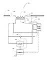
- FIG. 4is an exemplary block diagram 400 of an embodiment of the disclosed active impedance injection module using multi-turn primary windings for distributed active impedance injection on a HV transmission line.
- FIG. 4Ais an exemplary schematics of the multi-turn primary transformer as per an embodiment of the current invention.
- the multiple secondary turnsare deliberately not shown in order to provide a simpler drawing.
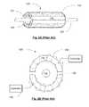
- FIG. 4Bshows an exemplary cross section of the multi-turn transformer of FIG. 4A .
- FIG. 5is a representation of a high voltage transmission line showing various ways the distributed active impedance injection modules are to be supported while being directly attached to the HV-transmission lines and operating at line voltage as per the embodiments of the invention.
- distributed dynamic-control modulesdistributed active impedance injection modules
- These distributed dynamic control modulesare directly attached to the HV-Transmission line and are at line potential while in operation.
- the distributed dynamic control modulesare enabled to operate by extracting power from the HV-Transmission line for control and for generating the necessary voltages to be impressed on the High Voltage (HV) transmission line.
- the modulesgenerate voltages at the right phase angle for injection on to the HV-transmission line, through the multi-turn transformer, to provide the necessary inductive or capacitive impedance during operation.
- the inventiondisclosed the use of the multi-turn transformer having multi-turn primary winding connected in series with the HV transmission line 108 by cutting and splicing in the winding.
- the secondary side of the multi-turn transformer and all associated circuitryare electrically isolated from the ground.
- one side of the secondary windingis connected to the primary winding to provide a virtual ground or “floating ground” reference and also partly to protect the secondary-side circuits form stray fields.
- the virtual ground 408can be established by connecting the negative dc link of the inverter/electronic injection module to the HV transmission line. Further, both may be grounded for effective operation. Different power-electronics topologies may necessitate other grounding schemes and these schemes do not effect the key invention but, rather, are specific implementations.
- the distributed control modulesIn order for the distributed control modules to be successfully accepted by utilities and installed on lines, these distributed control modules have to be smart and self-aware, remotely controllable and configurable.
- the modulesshould be of a reasonable weight compared to the line segment over which these are to be installed, even where the modules are suspended in an insulated fashion from the towers or are supported by additional support structures. These should also have a low wind resistance to reduce the effect of wind loading on the line/tower/special support structure employed.
- all the electronic components and circuits of the moduleshould have very high reliability to reduce the probability of line down times due to failure of the modules/components used therein.
- the splicing connection of the module to the HV transmission linealso has to have high reliability.
- the invention disclosedprovides distributed active control having very high reliability and capability for power flow and line balancing across the multiple high-voltage transmission lines used for power transmission on the high power grid system.
- the inventionovercomes the issues of the prior art implementations discussed and meet the criteria set for the use of the distributed control modules that are discussed below.
- the disclosed invention for increasing the impressed voltage or impedance on the transmission lineuses multiple turns on the primary winding of a series-connected injection transformer. Increasing the number of turns in the primary winding alters the turns ratio of the transformer, and allows the distributed active impedance injection module (injection module) to have a greater impact. Since the primary winding of the injection transformer need to be in series with the HV transmission line, the use of additional turns of the primary winding requires the HV transmission line to be cut and the ends of the winding to be spliced in series with the HV transmission line.
- the advantages of the disclosed multi-turn primary transformerinclude the ability to inject higher voltages, with 90-degree lead or lag angle, providing inductive or capacitive impedances respectively, on to the HV transmission line for power flow control and grid optimization.
- the transformercan also be designed such that the—power-rating-to-weight ratio (kVA per kg) of the unit can be increased, increasing the economy of the unit as well.
- the use of the multi-turn primary windingalso allow the preferred use of non-gapped transformer core, with high-permeability core materials, thereby reducing the flux leakage and improving power transfer between the primary and secondary windings.
- the impedance injection modulesallows for significantly greater “N+X” system reliability, where N is the required number of distributed modules, and X is the number of extra redundant modules. Therefore, by ensuring the reliability of each unit by itself being sufficient for use by the utilities, the added extra redundant distributed active-impedance control modules provide an additional layer of “system” reliability over and above the unit reliability.
- the use of these distributed impedance injection modulesalso provide the intelligence at the point of impact, for providing fast response to any changes in the optimum characteristics of the lines while transferring power. This in turn results in a grid using distributed injection modules of high reliability, capable of providing very high system reliability, acceptable to all the utilities.
- the use of the distributed impedance injection moduleshence are enabled to provide the best capability to balance the power transmitted over the HV-transmission-lines of the power grid.
- FIG. 4is an exemplary block diagram 400 of an implementation of the active impedance injection module (injection module) of the current invention.
- the injection module 400comprises a multi-turn transformer 400 A that has its primary winding 403 connected directly to the transmission line 108 by breaking the line and attaching the two ends of the primary winding 403 , by splicing into the line segment as shown in FIG. 4A at 401 and 402 .
- the primary winding 403is in series with the HV transmission line, 108 and carries the total current carried by the transmission line, 108 .
- a ribbon conductor or continuously transported cable or a braided ribbon conductormay be used, instead of the standard conductor, for the primary winding 403 , as shown in the exemplary cross section FIG. 4B of the multi-turn transformer, 400 A.
- the ribbon/braided ribbon conductor when used,also helps to reduce the over all weight of the conductor used and hence reduce the weight of the whole injection module 400 .
- a conductive foilmay also be used instead of the standard conductor in some cases to reduce the weight and improve the current carrying capability.
- a non-gapped transformer core 409is used to allow the maximum coupling possible between the primary winding 403 and the secondary winding 404 of the multi-turn transformer 400 A.
- the secondary winding 404 of the transformercouples to the primary winding 403 and is floating with respect to the primary winding.
- An exemplary virtual ground at the potential of the HV transmission line 108is established by connecting one side of the secondary winding of the multi-turn transformer to the HV transmission line that enables the injection module 400 itself to be floating at high voltage of the HV transmission line 108 during operation.
- a second low-voltage transformer 302 in the secondary circuitis connected to a power supply 303 within the injector module 400 that generates the necessary power required for the low-voltage electronics comprising the sensing, communication and control circuitry, all of which are lumped in the block diagram of the module as controller 406 , the voltage converter 405 and the secondary winding shorting switch 304 .
- the voltage converter or simply converter 405may be of any appropriate design, as such devices of various designs are well known in the art. Typically such devices are configured to inject an inductive load onto the high voltage transmission line, and may also have the capability of injecting a capacitive load on the transmission for power factor control, and may further be capable of controlling harmonic content in the high-voltage transmission line.
- Such devicesare also known by other names, such as by way of example, inverters or converters/inverters.
- An exemplary device of this general typeis the combination of the inverter 71 and energy storage 74 of U.S. Pat. No. 7,105,952, though many other examples of such devices are well known. These devices typically act as active impedances to controllably impose the desired impedance onto the high-voltage transmission line.
- the controller 410 used in the preferred embodimentsincludes a transceiver for receiving control signals and reporting on high voltage transmission line conditions, etc.
- the shorting switch 304is activated to prevent damage to the circuits connected across the secondary winding 404 during occurrence of high transients on the HV transmission line due to a short circuit or lightning strikes, or even for prolonged overloads
- the controller 406has sensor circuitry for monitoring the status of the line and for triggering the protection circuits 304 , and a transceiver establishing a communication capability 410 for inter-link communication and for accepting external configuration and control commands, which are used to provide additional instructions to the converter 406 .
- the voltage converter 405is an active voltage converter that, based on input from the controller 406 , generates the necessary leading or lagging voltages of sufficient magnitude, to be impressed on the secondary winding 404 of the power line transformer of the distributed active impedance injection module 400 , to be coupled to the HV transmission line 108 through the series-connected multi-turn primary winding 403 of the transformer.
- This injected voltage at the appropriate phase angleis able to provide the necessary impedance input capability for balancing the power transfer over the grid in a distributed fashion.
- the multi-turn primary 403 of the disclosed transformer 400 A coupled to the HV-transmission line 108is hence the main enabler for implementing the active distributed control of the power transfer and balancing of the grid.
- the current applicationaddresses the advantages and features of the use of multi-turn secondary windings 403 of a distributed active impedance injection module (injector module) 400 attached to the HV transmission line 108 .
- the multi-turn transformer 400 Ais able to impress a higher voltage on the power HV transmission line with a given transformer core size and weight while the connected circuits of the secondary winding 404 (converter 405 , controller 406 and protection switch 304 ) of the transformer 400 A are able to operate at lower voltage ranges with the proper turns ration selection, that are typical of power-electronics components commercially available.
- injection module 400allows fast response to changes in loading of the HV transmission lines at or close to the point of change for dynamic control and balancing of the transmission lines.
- the injector module 400 of the current inventionis not confined to substations, as in the past, but is enabled to provide power flow control capability within existing utility right-of-way corridors in a distributed fashion.
- the use of multi-turn primary winding 403also allows the typical use of non-gapped core for the transformer improving the weight and power transfer coupling of the device to the HV transmission line 108 .
- FIG. 5shows the typical attachment methods 500 possible for supporting the injection modules 400 connected to the HV transmission lines 108 .
- the on-line attachment 501is the typical prior art attachment used for the static modules, which connects the module to the line directly, with no additional support and lets the line supports take the weight of the module and the line. Though this is acceptable, this type of attachment is not the preferred one for the injection modules 400 , of the current invention.
- the preferred attachment for these impedance injection modules 400are with additional support, directly connected by supporting insulators 502 on the HV transmission towers 510 or by using special support structures 511 with insulated supports 503 for providing the additional weight carrying capability for the distributed module.
- the above support methodsalso improve the reliability of the structures and system during extreme climatic disturbances.
Landscapes
- Engineering & Computer Science (AREA)
- Power Engineering (AREA)
- Microelectronics & Electronic Packaging (AREA)
- Cable Transmission Systems, Equalization Of Radio And Reduction Of Echo (AREA)
Abstract
Description
- 1. The need is to have a distributed module that can generate and supply the required range of inductive and capacitive impedances (generating the necessary leading or lagging power) to the transmission line to provide the necessary control for line balancing.
- 2. Provide the above capability at a reasonable cost point-preferably by using standard off-the-shelf power-electronics components; this means that the secondary winding and associated circuits operate at voltages and current levels normally seen in high-volume power-electronic applications. Using off-the-shelf power-electronics components means using general-purpose power-electronics components that are also manufactured and sold in the ordinary course of business for other uses.
- 3. The third is the need for reliability of the distributed modules to be high enough to eliminate failures and related line shut downs to an acceptable level for the Utilities—this is achievable if standard power-electronics components, with associated high reliability can be used in the secondary circuits.
- 4. The final need is to have relatively low weight and low wind-capture cross section for the module to be attached to the HV-transmission line directly or with minimum extra support.
Claims (11)
Priority Applications (1)
| Application Number | Priority Date | Filing Date | Title |
|---|---|---|---|
| US15/975,373US10424929B2 (en) | 2015-12-08 | 2018-05-09 | Transformers with multi-turn primary windings for dynamic power flow control |
Applications Claiming Priority (3)
| Application Number | Priority Date | Filing Date | Title |
|---|---|---|---|
| US201562264739P | 2015-12-08 | 2015-12-08 | |
| US15/055,422US10418814B2 (en) | 2015-12-08 | 2016-02-26 | Transformers with multi-turn primary windings for dynamic power flow control |
| US15/975,373US10424929B2 (en) | 2015-12-08 | 2018-05-09 | Transformers with multi-turn primary windings for dynamic power flow control |
Related Parent Applications (1)
| Application Number | Title | Priority Date | Filing Date |
|---|---|---|---|
| US15/055,422DivisionUS10418814B2 (en) | 2015-12-08 | 2016-02-26 | Transformers with multi-turn primary windings for dynamic power flow control |
Publications (2)
| Publication Number | Publication Date |
|---|---|
| US20180262006A1 US20180262006A1 (en) | 2018-09-13 |
| US10424929B2true US10424929B2 (en) | 2019-09-24 |
Family
ID=58799288
Family Applications (2)
| Application Number | Title | Priority Date | Filing Date |
|---|---|---|---|
| US15/055,422Active2037-05-11US10418814B2 (en) | 2015-12-08 | 2016-02-26 | Transformers with multi-turn primary windings for dynamic power flow control |
| US15/975,373ActiveUS10424929B2 (en) | 2015-12-08 | 2018-05-09 | Transformers with multi-turn primary windings for dynamic power flow control |
Family Applications Before (1)
| Application Number | Title | Priority Date | Filing Date |
|---|---|---|---|
| US15/055,422Active2037-05-11US10418814B2 (en) | 2015-12-08 | 2016-02-26 | Transformers with multi-turn primary windings for dynamic power flow control |
Country Status (3)
| Country | Link |
|---|---|
| US (2) | US10418814B2 (en) |
| EP (1) | EP3387747B1 (en) |
| WO (1) | WO2017099928A1 (en) |
Families Citing this family (15)
| Publication number | Priority date | Publication date | Assignee | Title |
|---|---|---|---|---|
| US10180696B2 (en) | 2015-12-08 | 2019-01-15 | Smart Wires Inc. | Distributed impedance injection module for mitigation of the Ferranti effect |
| US10418814B2 (en) | 2015-12-08 | 2019-09-17 | Smart Wires Inc. | Transformers with multi-turn primary windings for dynamic power flow control |
| US10903653B2 (en) | 2015-12-08 | 2021-01-26 | Smart Wires Inc. | Voltage agnostic power reactor |
| US10008317B2 (en)* | 2015-12-08 | 2018-06-26 | Smart Wires Inc. | Voltage or impedance-injection method using transformers with multiple secondary windings for dynamic power flow control |
| US10199150B2 (en) | 2015-12-10 | 2019-02-05 | Smart Wires Inc. | Power transmission tower mounted series injection transformer |
| US10097037B2 (en) | 2016-02-11 | 2018-10-09 | Smart Wires Inc. | System and method for distributed grid control with sub-cyclic local response capability |
| US10218175B2 (en) | 2016-02-11 | 2019-02-26 | Smart Wires Inc. | Dynamic and integrated control of total power system using distributed impedance injection modules and actuator devices within and at the edge of the power grid |
| US10651633B2 (en) | 2016-04-22 | 2020-05-12 | Smart Wires Inc. | Modular, space-efficient structures mounting multiple electrical devices |
| US10468880B2 (en) | 2016-11-15 | 2019-11-05 | Smart Wires Inc. | Systems and methods for voltage regulation using split-conductors with loop current reduction |
| US10666038B2 (en) | 2017-06-30 | 2020-05-26 | Smart Wires Inc. | Modular FACTS devices with external fault current protection |
| DE102017215460A1 (en)* | 2017-09-04 | 2019-03-07 | Siemens Aktiengesellschaft | Arrangement for connection to a high-voltage network with adjustable impedance |
| JP6251838B1 (en)* | 2017-09-11 | 2017-12-20 | 高周波熱錬株式会社 | Output current synthesizer and power supply device |
| US11476031B1 (en) | 2018-08-01 | 2022-10-18 | Smart Wires Inc. | Current adaptive reactor structure |
| US10790878B1 (en)* | 2018-08-13 | 2020-09-29 | Smart Wires Inc. | Systems and methods for real-time communication among a cluster of impedance injection nodes in a power distribution system |
| US11776757B1 (en)* | 2019-11-20 | 2023-10-03 | Smart Wires Inc. | Method for mounting high voltage capacitor banks |
Citations (130)
| Publication number | Priority date | Publication date | Assignee | Title |
|---|---|---|---|---|
| US2237812A (en) | 1940-02-23 | 1941-04-08 | Gen Electric | Portable unit substation |
| US2551841A (en) | 1946-11-27 | 1951-05-08 | Westinghouse Electric Corp | Electrical apparatus |
| US3556310A (en) | 1968-05-27 | 1971-01-19 | Jack Loukotsky | Prefabricated modular power substation |
| US3704001A (en) | 1970-11-17 | 1972-11-28 | Clifford E Sloop | Mounting bracket |
| US3750992A (en) | 1972-06-26 | 1973-08-07 | E Johnson | Transformer mounting assembly |
| US3913003A (en) | 1973-10-31 | 1975-10-14 | Siemens Ag | Compact converter building block system |
| US4025824A (en) | 1976-02-12 | 1977-05-24 | Cheatham Harry P | Transformer support rack |
| US4057736A (en) | 1974-09-13 | 1977-11-08 | Jeppson Morris R | Electrical power generation and distribution system |
| US4103853A (en) | 1976-12-22 | 1978-08-01 | Mcgraw-Edison Company | Aluminum cluster mount |
| US4164345A (en) | 1978-02-03 | 1979-08-14 | Arnold William L | Safety cradle for transformer repair |
| US4200899A (en) | 1976-07-16 | 1980-04-29 | Grinshtein Vladimir Y | Outdoor high-voltage switchgear |
| US4277639A (en) | 1979-03-27 | 1981-07-07 | Asea Aktiebolag | High-voltage installation including heavy electrical apparatus suspended by insulator means |
| US4286207A (en) | 1980-04-14 | 1981-08-25 | Westinghouse Electric Corp. | High-power AC voltage stabilizer |
| US4323722A (en) | 1980-09-24 | 1982-04-06 | The United States Of America As Represented By The United States Department Of Energy | Overhead electric power transmission line jumpering system for bundles of five or more subconductors |
| US4367512A (en) | 1978-11-24 | 1983-01-04 | Kabushiki Kaisha Meidensha | Transportable power supply substation |
| US4514950A (en) | 1981-11-27 | 1985-05-07 | Goodson Jr Albert A | Building framing system and method |
| US4562360A (en) | 1981-10-13 | 1985-12-31 | Mitsubishi Denki Kabushiki Kaisha | Mobile substation |
| US4577826A (en) | 1983-07-11 | 1986-03-25 | Asea Aktiebolag | Stand structure for supporting electric high voltage equipment |
| CH660094A5 (en) | 1978-10-27 | 1987-03-13 | Hazemeijer Bv | SUBSTATION AND MAIN DISTRIBUTION STATION FOR DISTRIBUTION OF ELECTRICAL ENERGY. |
| US4710850A (en) | 1986-02-19 | 1987-12-01 | Siemens Aktiengesellschaft | Tower design for high-voltage systems |
| US4821138A (en) | 1986-05-23 | 1989-04-11 | Sumitomo Electric Industries, Ltd. | Monitoring device for overhead power transmission system |
| US4903927A (en) | 1988-09-29 | 1990-02-27 | Aluma-Form, Inc. | Electrical equipment cluster mount |
| US5006846A (en) | 1987-11-12 | 1991-04-09 | Granville J Michael | Power transmission line monitoring system |
| US5023768A (en) | 1989-11-24 | 1991-06-11 | Varian Associates, Inc. | High voltage high power DC power supply |
| US5032738A (en) | 1986-01-22 | 1991-07-16 | Vithayathil John J | Scheme for rapid adjustment of network impedance |
| US5193774A (en) | 1992-05-26 | 1993-03-16 | Rogers J W | Mounting bracket apparatus |
| US5461300A (en) | 1993-03-30 | 1995-10-24 | Electric Power Research Institute, Inc. | Phase angle regulating transformer with a single core per phase |
| US5469044A (en) | 1995-01-05 | 1995-11-21 | Westinghouse Electric Corporation | Transmission line power flow controller with unequal advancement and retardation of transmission angle |
| US5513061A (en) | 1993-12-09 | 1996-04-30 | Long Island Lighting Company | Apparatus and method for distributing electrical power |
| US5610501A (en) | 1995-02-01 | 1997-03-11 | Westinghouse Electric Corporation | Dynamic power and voltage regulator for an ac transmission line |
| US5648888A (en) | 1995-12-27 | 1997-07-15 | Hydro-Quebec | Power distribution substation |
| US5844462A (en) | 1996-04-29 | 1998-12-01 | Alliedsignal Inc. | Magnetic core-coil assembly for spark ignition systems |
| US5884886A (en) | 1994-02-26 | 1999-03-23 | Asea Brown Boveri Ag | Support frame for a structural component |
| US5886888A (en) | 1995-04-27 | 1999-03-23 | Mitsubishi Denki Kabushiki Kaisha | Voltage source type power converting apparatus |
| US5986617A (en) | 1998-08-31 | 1999-11-16 | Lucent Technologies | Multiband antenna matching unit |
| US6088249A (en) | 1997-12-02 | 2000-07-11 | Power Circuit Innovations, Inc. | Frequency modulated ballast with loosely coupled transformer |
| US6134105A (en) | 1998-01-06 | 2000-10-17 | Lueker; Mark David | Portable command center |
| US6147581A (en) | 1999-11-17 | 2000-11-14 | Asea Brown Boveri Inc. | Universal transformer tank for pole-mounted distribution transformers |
| US6215653B1 (en) | 1999-07-15 | 2001-04-10 | Aep Resources Services Company | Modular electrical substation and method of constructing same |
| US6233137B1 (en) | 2000-05-25 | 2001-05-15 | Mathias Kolos | Compact power distribution substation |
| US6335613B1 (en) | 2000-12-04 | 2002-01-01 | Abb T&D Technology Ltd. | Versatile power flow transformers for compensating power flow in a transmission line |
| US20020005668A1 (en) | 1998-12-04 | 2002-01-17 | Pierre Couture | Power flow management in an electric power grid |
| US20020042696A1 (en) | 1999-04-09 | 2002-04-11 | Public Service Company Of New Mexico | Utility station automated design system and method |
| JP2002199563A (en) | 2000-12-26 | 2002-07-12 | Hitachi Cable Ltd | How to branch overhead power lines |
| US20030006652A1 (en) | 1998-12-04 | 2003-01-09 | Hydro-Quebec | Switching apparatus and method for a segment of an electric power line |
| US20030098768A1 (en) | 2001-11-23 | 2003-05-29 | Roland Hoffmann | Winding for a transformer or a coil and method for producing the winding |
| US20040153215A1 (en) | 2003-01-31 | 2004-08-05 | Adrian Kearney | Fault control and restoration in a multi-feed power network |
| US20040217836A1 (en) | 2003-04-30 | 2004-11-04 | Marc-Antoine Archambault | Distribution transformer |
| US6831377B2 (en) | 2000-05-03 | 2004-12-14 | University Of Southern California | Repetitive power pulse generator with fast rising pulse |
| JP2005045888A (en) | 2003-07-25 | 2005-02-17 | Toshiba Corp | Power distribution tower |
| US20050052801A1 (en) | 2003-09-05 | 2005-03-10 | Ghali Gamal A. | Method for tapping a high voltage transmission line and substation using the same |
| US20050073200A1 (en)* | 2003-10-03 | 2005-04-07 | Divan Deepakraj M. | Distributed floating series active impedances for power transmission systems |
| US20050194944A1 (en) | 2004-03-04 | 2005-09-08 | Folts Douglas C. | Dynamic reactive compensation system and method |
| US20050205726A1 (en) | 2003-02-21 | 2005-09-22 | Areva T&D Sa | Articulated support with lateral movement for high-voltage or medium-voltage electrical plant |
| US20060085097A1 (en) | 2004-10-16 | 2006-04-20 | Courtney Thomas A | Power distribution substation |
| US20070135972A1 (en) | 2005-10-07 | 2007-06-14 | Jay Jacobson | Method and system for improving the efficiency and reliability of a power grid |
| US20070250217A1 (en) | 2006-04-25 | 2007-10-25 | Korea Electric Power Corporation | System and method for automatically operating upfc (unified power flow controller) connected to scada (supervisory control and data acquisition) |
| US20080103737A1 (en) | 2006-10-31 | 2008-05-01 | Yoon Jong-Su | Simulation system for facts connected online to scada system |
| US20080157728A1 (en) | 2006-08-04 | 2008-07-03 | Mitsubishi Electric Corporation | Reactive-power control apparatus and reactive-power compensator using the same |
| WO2008082820A1 (en) | 2006-12-28 | 2008-07-10 | 3M Innovative Properties Company | Overhead electrical power transmission line |
| US20080177425A1 (en) | 2005-06-24 | 2008-07-24 | Abb Research Ltd | Damping electromechanical oscillations in power systems |
| US20080278976A1 (en) | 2007-05-11 | 2008-11-13 | Schneider Robert S | Dynamic voltage sag correction |
| US20080310069A1 (en) | 2005-01-31 | 2008-12-18 | Deepakraj Malhar Divan | Systems and Methods for Distributed Series Compensation of Power Lines Using Passive Devices |
| US20090243876A1 (en) | 2005-09-16 | 2009-10-01 | Jean-Louis Lilien | Device, system and method for real-time monitoring of overhead power lines |
| US20090281679A1 (en) | 2008-05-09 | 2009-11-12 | Taft Jeffrey D | Intelligent monitoring of an electrical utility grid |
| US20100026275A1 (en) | 2007-02-20 | 2010-02-04 | Abb Limited | Flux control system for active voltage conditioning |
| US20100177450A1 (en) | 2009-01-12 | 2010-07-15 | Grid Logic | Method and devices for stabilizing electric grid power |
| US20100213765A1 (en) | 2007-09-26 | 2010-08-26 | Siemens Aktiengesellschaft | Energy supply |
| US7834736B1 (en) | 2009-07-31 | 2010-11-16 | Abb Technology Ag | Dry type pole-mounted transformer |
| US20100302744A1 (en) | 2009-05-29 | 2010-12-02 | Rosendin Electric, Inc. | Various methods and apparatuses for an integrated power distribution platform |
| US20110060474A1 (en) | 2009-09-04 | 2011-03-10 | Voltwerk Electronics Gmbh | Power control device for a power grid, comprising a control unit for controlling an energy flow between the power generation unit, the energy storage unit, the consumer unit and/or the power grid |
| US7932621B1 (en) | 2010-01-28 | 2011-04-26 | James Patrick Spellman | Method and apparatus for an integrated wind-solar energy system utilizing an existing wind turbine infrastructure |
| US20110095162A1 (en) | 2009-04-06 | 2011-04-28 | Pelco Products, Inc. | Cable retainer for utility pole base |
| US20110106321A1 (en) | 2009-11-03 | 2011-05-05 | Spirae, Inc. | Dynamic distributed power grid control system |
| US20110172837A1 (en) | 2007-08-28 | 2011-07-14 | Forbes Jr Joseph W | System and method for estimating and providing dispatchable operating reserve energy capacity through use of active load management |
| KR101053514B1 (en) | 2011-05-20 | 2011-08-03 | 티앤제이건설 주식회사 | Jumper wire connection fixing device for overhead transmission line |
| US20120105023A1 (en) | 2010-10-27 | 2012-05-03 | Satcon Technology Corporation | Automatic ac bus voltage regulation for power distribution grids |
| US20120146335A1 (en) | 2010-12-08 | 2012-06-14 | Northern Power Systems, Inc. | Wind Power Unit Having an Underslung Transformer |
| US20120205981A1 (en) | 2009-09-15 | 2012-08-16 | The University Of Western Ontario | Utilization of distributed generator inverters as statcom |
| US8270558B2 (en) | 2007-09-10 | 2012-09-18 | St-Ericsson Sa | Electronic device, barrel shifter unit and method of barrel shifting |
| US20120242150A1 (en) | 2010-08-04 | 2012-09-27 | Kunihiro Ukai | Power supply system, control device of power supply system, operation method of power supply system, and control method of power supply system |
| US20120255920A1 (en) | 2011-04-11 | 2012-10-11 | Abb Technology Ag | Electrical equipment mounting frame |
| US20120293920A1 (en) | 2009-10-20 | 2012-11-22 | Abb Technology Ltd | System having electrical equipment integrated on a structure and a method for isolation of electrical equipment thereof |
| US20130002032A1 (en) | 2011-06-28 | 2013-01-03 | Shigeki Mori | Power grid operation control system, device, and method |
| US20130033103A1 (en) | 2011-08-02 | 2013-02-07 | Mcjunkin Samuel T | Systems and Methods For Distributed Impedance Compensation In Subsea Power Distribution |
| US20130044407A1 (en) | 2011-08-16 | 2013-02-21 | Lsis Co., Ltd. | Solid insulated switchgear |
| US20130094264A1 (en) | 2010-03-15 | 2013-04-18 | Alstom Technolgoy Ltd. | Static var compensator with multilevel converter |
| US8441778B1 (en) | 2010-12-22 | 2013-05-14 | Stephen L. Ashmore | Modular substation feeder assembly |
| US20130128636A1 (en) | 2010-07-30 | 2013-05-23 | Alstom Technology Ltd | HVDC Converter Comprising Fullbridge Cells For Handling A DC Side Short Circuit |
| US20130169044A1 (en) | 2010-09-13 | 2013-07-04 | Aker Susea AS | Stable subsea electric power transmission to run subsea high speed motors |
| US20130184894A1 (en) | 2010-11-08 | 2013-07-18 | Nec Corporation | Electric power grid control system and method for electric power control |
| US20130182355A1 (en) | 2010-07-28 | 2013-07-18 | Ormazabal Y Cia, S.L.U | Connection device for transformer substation modules |
| US8497592B1 (en) | 2011-08-31 | 2013-07-30 | Thomas Jones | Utility pole mountable vertical axis wind turbine |
| US20130200617A1 (en) | 2010-04-06 | 2013-08-08 | GE Energy Power Conversion Tecnology Ltd | Power transmission systems |
| CN103256337A (en) | 2013-04-24 | 2013-08-21 | 中国电力科学研究院 | Electrical equipment support-type damping control system and damper model selecting method and device thereof |
| US20130249321A1 (en) | 2012-03-20 | 2013-09-26 | The Boeing Company | Method and Apparatus for Anti-Icing and Deicing Power Transmission Lines |
| US20130277082A1 (en) | 2012-04-24 | 2013-10-24 | Elwha LLC, a limited liability company of the State of Delaware | Transmission-line coupled closed-cycle heat transfer device |
| US20130345888A1 (en) | 2012-06-20 | 2013-12-26 | Joseph W. Forbes, Jr. | Method and apparatus for actively managing electric power over an electric power grid |
| US20140008982A1 (en) | 2009-05-07 | 2014-01-09 | Virginia Electric And Power Company | Voltage conservation using advanced metering infrastructure and substation centralized voltage control |
| US20140025217A1 (en) | 2011-03-25 | 2014-01-23 | Zhuhai Unitech Power Technology Co., Ltd. | Device and method for self-healing control of a multi-level power grid |
| US20140032000A1 (en) | 2012-07-30 | 2014-01-30 | Siemens Corporation | Power System Stabilization Using Distributed Inverters |
| WO2014035881A1 (en) | 2012-08-28 | 2014-03-06 | Smart Wire Grid, Inc. | Power line reactance module and applications |
| US20140111297A1 (en) | 2012-10-18 | 2014-04-24 | Manufacturing Systems and Equipment Inc. | Wound transformer core and method of manufacture |
| US20140129195A1 (en) | 2011-06-24 | 2014-05-08 | State Grid Corporation Of China | Real time dynamic physics simulation device of flexible dc transmission system |
| US20140132229A1 (en) | 2012-11-02 | 2014-05-15 | North Carolina State University | Static synchronous compensator systems and related methods |
| WO2014074956A1 (en) | 2012-11-08 | 2014-05-15 | Cameron D | Modular structural system for solar panel installation |
| US20140153383A1 (en) | 2011-06-08 | 2014-06-05 | Socpra Sciences Et Genie S.E.C. | Distributed electrical load management method and system for controlling community loads |
| CN203668968U (en) | 2013-12-18 | 2014-06-25 | 中国能源建设集团安徽省电力设计院 | Support supporting component used for transformer substation outdoor AIS electric equipment |
| WO2014099876A1 (en) | 2012-12-18 | 2014-06-26 | Smart Wire Grid, Inc. | Installation fixture for installing devices on power lines |
| US20140188689A1 (en) | 2012-12-31 | 2014-07-03 | Battelle Memorial Institute | Distributed hierarchical control architecture for integrating smart grid assets during normal and disrupted operations |
| US20140203640A1 (en) | 2011-09-12 | 2014-07-24 | Aker Subsea As | Device for stable subsea electric power transmission to run subsea high speed motors or other subsea loads |
| US20140210213A1 (en) | 2013-01-31 | 2014-07-31 | APR Energy, LLC | Scalable portable modular power plant |
| US8816527B1 (en) | 2013-03-27 | 2014-08-26 | Smart Wire Grid, Inc. | Phase balancing of power transmission system |
| US20140246914A1 (en) | 2011-09-12 | 2014-09-04 | Alstom Technology Ltd. | Sub-Synchronous Oscillation Damping By Shunt Facts Apparatus |
| US20140247554A1 (en) | 2011-10-07 | 2014-09-04 | Sabic Innovative Plastics Ip B.V. | Inverter housing system |
| US20140268458A1 (en) | 2013-03-14 | 2014-09-18 | Innovolt, Inc. | Systems and methods for detecting and determining sources of power disturbances in connection with effective remediation |
| US20140266288A1 (en) | 2013-03-15 | 2014-09-18 | Control Techniques Limited | Electrical Fault Detection |
| US20140312859A1 (en) | 2013-03-27 | 2014-10-23 | Smart Wire Grid, Inc. | Phase balancing of power transmission system |
| US8890373B2 (en) | 2011-04-04 | 2014-11-18 | Eaton Corporation | Power distribution systems using distributed current sensing |
| US20140347158A1 (en) | 2013-05-24 | 2014-11-27 | Keithley Instruments, Inc. | Isolation transformer for use in isolated dc-to-dc switching power supply |
| US20150029764A1 (en) | 2012-02-24 | 2015-01-29 | Board Of Trustees Of Michigan State University | Transformer-less unified power flow controller |
| US20150051744A1 (en) | 2013-08-19 | 2015-02-19 | Board Of Trustees Of Michigan State University | Linear Optimal Power Flow System and Method |
| JP2015086692A (en) | 2013-09-27 | 2015-05-07 | 株式会社アークリエイト | Steel structure pile pillar-to-base beam joint integrated method |
| WO2015074538A1 (en) | 2013-11-21 | 2015-05-28 | 国家电网公司 | Automatic unfolding type on-site calibration vehicle for high-voltage transformers |
| US20150184415A1 (en) | 2013-01-10 | 2015-07-02 | Kevin M. Bushore | Methods and apparatuses of supporting and bracing a utility pole |
| WO2015119789A1 (en) | 2014-02-07 | 2015-08-13 | Smart Wire Grid, Inc. | Detecting geomagnetically induced currents with powerline devices |
| US20160036341A1 (en) | 2014-07-31 | 2016-02-04 | Korea University Research And Business Foundation | Power grid frequency flexible operation system and method using the same |
| US9563218B2 (en) | 2013-03-15 | 2017-02-07 | Dominion Resources, Inc. | Electric power system control with measurement of energy demand and energy efficiency using t-distributions |
| US20170163036A1 (en) | 2015-12-08 | 2017-06-08 | Smart Wires Inc. | Transformers with Multi-Turn Primary Windings for Dynamic Power Flow Control |
| US20170169928A1 (en) | 2015-12-10 | 2017-06-15 | Smart Wires Inc. | Power Transmission Tower Mounted Series Injection Transformer |
Family Cites Families (3)
| Publication number | Priority date | Publication date | Assignee | Title |
|---|---|---|---|---|
| GB2324389B (en)* | 1997-04-15 | 2001-04-11 | King Kuen Hau | Digital controlled voltage compensator |
| IT1309253B1 (en)* | 1999-05-18 | 2002-01-16 | Varat S R L | ALTERNATING CURRENT POWER SUPPLY AND ELECTRONICALLY STABILIZED VOLTAGE |
| US7372709B2 (en)* | 2003-09-11 | 2008-05-13 | The Board Of Trustees Of The University Of Illinois | Power conditioning system for energy sources |
- 2016
- 2016-02-26USUS15/055,422patent/US10418814B2/enactiveActive
- 2016-11-08WOPCT/US2016/061009patent/WO2017099928A1/ennot_activeCeased
- 2016-11-08EPEP16873546.2Apatent/EP3387747B1/enactiveActive
- 2018
- 2018-05-09USUS15/975,373patent/US10424929B2/enactiveActive
Patent Citations (177)
| Publication number | Priority date | Publication date | Assignee | Title |
|---|---|---|---|---|
| US2237812A (en) | 1940-02-23 | 1941-04-08 | Gen Electric | Portable unit substation |
| US2551841A (en) | 1946-11-27 | 1951-05-08 | Westinghouse Electric Corp | Electrical apparatus |
| US3556310A (en) | 1968-05-27 | 1971-01-19 | Jack Loukotsky | Prefabricated modular power substation |
| US3704001A (en) | 1970-11-17 | 1972-11-28 | Clifford E Sloop | Mounting bracket |
| US3750992A (en) | 1972-06-26 | 1973-08-07 | E Johnson | Transformer mounting assembly |
| US3913003A (en) | 1973-10-31 | 1975-10-14 | Siemens Ag | Compact converter building block system |
| US4057736A (en) | 1974-09-13 | 1977-11-08 | Jeppson Morris R | Electrical power generation and distribution system |
| US4025824A (en) | 1976-02-12 | 1977-05-24 | Cheatham Harry P | Transformer support rack |
| US4200899A (en) | 1976-07-16 | 1980-04-29 | Grinshtein Vladimir Y | Outdoor high-voltage switchgear |
| US4103853A (en) | 1976-12-22 | 1978-08-01 | Mcgraw-Edison Company | Aluminum cluster mount |
| US4164345A (en) | 1978-02-03 | 1979-08-14 | Arnold William L | Safety cradle for transformer repair |
| CH660094A5 (en) | 1978-10-27 | 1987-03-13 | Hazemeijer Bv | SUBSTATION AND MAIN DISTRIBUTION STATION FOR DISTRIBUTION OF ELECTRICAL ENERGY. |
| US4367512A (en) | 1978-11-24 | 1983-01-04 | Kabushiki Kaisha Meidensha | Transportable power supply substation |
| US4277639A (en) | 1979-03-27 | 1981-07-07 | Asea Aktiebolag | High-voltage installation including heavy electrical apparatus suspended by insulator means |
| US4286207A (en) | 1980-04-14 | 1981-08-25 | Westinghouse Electric Corp. | High-power AC voltage stabilizer |
| US4323722A (en) | 1980-09-24 | 1982-04-06 | The United States Of America As Represented By The United States Department Of Energy | Overhead electric power transmission line jumpering system for bundles of five or more subconductors |
| US4562360A (en) | 1981-10-13 | 1985-12-31 | Mitsubishi Denki Kabushiki Kaisha | Mobile substation |
| US4514950A (en) | 1981-11-27 | 1985-05-07 | Goodson Jr Albert A | Building framing system and method |
| US4577826A (en) | 1983-07-11 | 1986-03-25 | Asea Aktiebolag | Stand structure for supporting electric high voltage equipment |
| US5032738A (en) | 1986-01-22 | 1991-07-16 | Vithayathil John J | Scheme for rapid adjustment of network impedance |
| US4710850A (en) | 1986-02-19 | 1987-12-01 | Siemens Aktiengesellschaft | Tower design for high-voltage systems |
| US4821138A (en) | 1986-05-23 | 1989-04-11 | Sumitomo Electric Industries, Ltd. | Monitoring device for overhead power transmission system |
| US5006846A (en) | 1987-11-12 | 1991-04-09 | Granville J Michael | Power transmission line monitoring system |
| US4903927A (en) | 1988-09-29 | 1990-02-27 | Aluma-Form, Inc. | Electrical equipment cluster mount |
| US5023768A (en) | 1989-11-24 | 1991-06-11 | Varian Associates, Inc. | High voltage high power DC power supply |
| US5193774A (en) | 1992-05-26 | 1993-03-16 | Rogers J W | Mounting bracket apparatus |
| US5461300A (en) | 1993-03-30 | 1995-10-24 | Electric Power Research Institute, Inc. | Phase angle regulating transformer with a single core per phase |
| US5513061A (en) | 1993-12-09 | 1996-04-30 | Long Island Lighting Company | Apparatus and method for distributing electrical power |
| US5884886A (en) | 1994-02-26 | 1999-03-23 | Asea Brown Boveri Ag | Support frame for a structural component |
| US5469044A (en) | 1995-01-05 | 1995-11-21 | Westinghouse Electric Corporation | Transmission line power flow controller with unequal advancement and retardation of transmission angle |
| US5610501A (en) | 1995-02-01 | 1997-03-11 | Westinghouse Electric Corporation | Dynamic power and voltage regulator for an ac transmission line |
| US5886888A (en) | 1995-04-27 | 1999-03-23 | Mitsubishi Denki Kabushiki Kaisha | Voltage source type power converting apparatus |
| US5648888A (en) | 1995-12-27 | 1997-07-15 | Hydro-Quebec | Power distribution substation |
| US5844462A (en) | 1996-04-29 | 1998-12-01 | Alliedsignal Inc. | Magnetic core-coil assembly for spark ignition systems |
| US6088249A (en) | 1997-12-02 | 2000-07-11 | Power Circuit Innovations, Inc. | Frequency modulated ballast with loosely coupled transformer |
| US6134105A (en) | 1998-01-06 | 2000-10-17 | Lueker; Mark David | Portable command center |
| US5986617A (en) | 1998-08-31 | 1999-11-16 | Lucent Technologies | Multiband antenna matching unit |
| US20020005668A1 (en) | 1998-12-04 | 2002-01-17 | Pierre Couture | Power flow management in an electric power grid |
| US6727604B2 (en) | 1998-12-04 | 2004-04-27 | Hydro-Quebec | Switching apparatus and method for a segment of an electric power line |
| US6486569B2 (en) | 1998-12-04 | 2002-11-26 | Hydro-Quebec | Power flow management in an electric power grid |
| US20030006652A1 (en) | 1998-12-04 | 2003-01-09 | Hydro-Quebec | Switching apparatus and method for a segment of an electric power line |
| US6895373B2 (en) | 1999-04-09 | 2005-05-17 | Public Service Company Of New Mexico | Utility station automated design system and method |
| US20020042696A1 (en) | 1999-04-09 | 2002-04-11 | Public Service Company Of New Mexico | Utility station automated design system and method |
| US6215653B1 (en) | 1999-07-15 | 2001-04-10 | Aep Resources Services Company | Modular electrical substation and method of constructing same |
| US6147581A (en) | 1999-11-17 | 2000-11-14 | Asea Brown Boveri Inc. | Universal transformer tank for pole-mounted distribution transformers |
| US6831377B2 (en) | 2000-05-03 | 2004-12-14 | University Of Southern California | Repetitive power pulse generator with fast rising pulse |
| US6233137B1 (en) | 2000-05-25 | 2001-05-15 | Mathias Kolos | Compact power distribution substation |
| US6335613B1 (en) | 2000-12-04 | 2002-01-01 | Abb T&D Technology Ltd. | Versatile power flow transformers for compensating power flow in a transmission line |
| JP2002199563A (en) | 2000-12-26 | 2002-07-12 | Hitachi Cable Ltd | How to branch overhead power lines |
| US20030098768A1 (en) | 2001-11-23 | 2003-05-29 | Roland Hoffmann | Winding for a transformer or a coil and method for producing the winding |
| US20040153215A1 (en) | 2003-01-31 | 2004-08-05 | Adrian Kearney | Fault control and restoration in a multi-feed power network |
| US20050205726A1 (en) | 2003-02-21 | 2005-09-22 | Areva T&D Sa | Articulated support with lateral movement for high-voltage or medium-voltage electrical plant |
| US7090176B2 (en) | 2003-02-21 | 2006-08-15 | Areva T&D Sa | Articulated support with lateral movement for high-voltage or medium-voltage electrical plant |
| US20040217836A1 (en) | 2003-04-30 | 2004-11-04 | Marc-Antoine Archambault | Distribution transformer |
| US6914195B2 (en) | 2003-04-30 | 2005-07-05 | Va Tech Transformateurs Ferranti-Packard (Quebec) Inc. | Distribution transformer |
| JP2005045888A (en) | 2003-07-25 | 2005-02-17 | Toshiba Corp | Power distribution tower |
| US20050052801A1 (en) | 2003-09-05 | 2005-03-10 | Ghali Gamal A. | Method for tapping a high voltage transmission line and substation using the same |
| US7193338B2 (en) | 2003-09-05 | 2007-03-20 | Ghali Gamal A | Method for tapping a high voltage transmission line and substation using the same |
| US20050073200A1 (en)* | 2003-10-03 | 2005-04-07 | Divan Deepakraj M. | Distributed floating series active impedances for power transmission systems |
| US7105952B2 (en) | 2003-10-03 | 2006-09-12 | Soft Switching Technologies Corporation | Distributed floating series active impendances for power transmission systems |
| US20050194944A1 (en) | 2004-03-04 | 2005-09-08 | Folts Douglas C. | Dynamic reactive compensation system and method |
| US7091703B2 (en) | 2004-03-04 | 2006-08-15 | American Superconductor Corporation | Dynamic reactive compensation system and method |
| US20060085097A1 (en) | 2004-10-16 | 2006-04-20 | Courtney Thomas A | Power distribution substation |
| US7352564B2 (en) | 2004-10-16 | 2008-04-01 | Eaton Corporation | Power distribution substation |
| US7835128B2 (en) | 2005-01-31 | 2010-11-16 | Georgia Tech Research Corporation | Systems and methods for distributed series compensation of power lines using passive devices |
| US20080310069A1 (en) | 2005-01-31 | 2008-12-18 | Deepakraj Malhar Divan | Systems and Methods for Distributed Series Compensation of Power Lines Using Passive Devices |
| US20080177425A1 (en) | 2005-06-24 | 2008-07-24 | Abb Research Ltd | Damping electromechanical oscillations in power systems |
| US8019484B2 (en) | 2005-06-24 | 2011-09-13 | Abb Research Ltd | Damping electromechanical oscillations in power systems |
| US20090243876A1 (en) | 2005-09-16 | 2009-10-01 | Jean-Louis Lilien | Device, system and method for real-time monitoring of overhead power lines |
| US20070135972A1 (en) | 2005-10-07 | 2007-06-14 | Jay Jacobson | Method and system for improving the efficiency and reliability of a power grid |
| US7460931B2 (en) | 2005-10-07 | 2008-12-02 | Jay Jacobson | Method and system for improving the efficiency and reliability of a power grid |
| US7642757B2 (en) | 2006-04-25 | 2010-01-05 | Korea Electric Power Corporation | System and method for automatically operating UPFC (unified power flow controller) connected to SCADA (supervisory control and data acquisition) |
| US20070250217A1 (en) | 2006-04-25 | 2007-10-25 | Korea Electric Power Corporation | System and method for automatically operating upfc (unified power flow controller) connected to scada (supervisory control and data acquisition) |
| US20080157728A1 (en) | 2006-08-04 | 2008-07-03 | Mitsubishi Electric Corporation | Reactive-power control apparatus and reactive-power compensator using the same |
| US7688043B2 (en) | 2006-08-04 | 2010-03-30 | Mitsubishi Electric Corporation | Reactive-power control apparatus and reactive-power compensator using the same |
| US8249836B2 (en) | 2006-10-31 | 2012-08-21 | Korea Electric Power Corporation | Simulation system for FACTS connected online to SCADA system |
| US20080103737A1 (en) | 2006-10-31 | 2008-05-01 | Yoon Jong-Su | Simulation system for facts connected online to scada system |
| WO2008082820A1 (en) | 2006-12-28 | 2008-07-10 | 3M Innovative Properties Company | Overhead electrical power transmission line |
| US20100026275A1 (en) | 2007-02-20 | 2010-02-04 | Abb Limited | Flux control system for active voltage conditioning |
| US20080278976A1 (en) | 2007-05-11 | 2008-11-13 | Schneider Robert S | Dynamic voltage sag correction |
| US20110172837A1 (en) | 2007-08-28 | 2011-07-14 | Forbes Jr Joseph W | System and method for estimating and providing dispatchable operating reserve energy capacity through use of active load management |
| US8996183B2 (en) | 2007-08-28 | 2015-03-31 | Consert Inc. | System and method for estimating and providing dispatchable operating reserve energy capacity through use of active load management |
| US8270558B2 (en) | 2007-09-10 | 2012-09-18 | St-Ericsson Sa | Electronic device, barrel shifter unit and method of barrel shifting |
| US20100213765A1 (en) | 2007-09-26 | 2010-08-26 | Siemens Aktiengesellschaft | Energy supply |
| US8310099B2 (en) | 2007-09-26 | 2012-11-13 | Siemens Aktiengesellschaft | Energy supply in which a plurality of components disposed along a transmission route each transform a voltage |
| US20090281679A1 (en) | 2008-05-09 | 2009-11-12 | Taft Jeffrey D | Intelligent monitoring of an electrical utility grid |
| US20100177450A1 (en) | 2009-01-12 | 2010-07-15 | Grid Logic | Method and devices for stabilizing electric grid power |
| US20110095162A1 (en) | 2009-04-06 | 2011-04-28 | Pelco Products, Inc. | Cable retainer for utility pole base |
| US20140008982A1 (en) | 2009-05-07 | 2014-01-09 | Virginia Electric And Power Company | Voltage conservation using advanced metering infrastructure and substation centralized voltage control |
| US20100302744A1 (en) | 2009-05-29 | 2010-12-02 | Rosendin Electric, Inc. | Various methods and apparatuses for an integrated power distribution platform |
| US8681479B2 (en) | 2009-05-29 | 2014-03-25 | Rosendin Electric, Inc. | Various methods and apparatuses for an integrated power distribution platform |
| US7834736B1 (en) | 2009-07-31 | 2010-11-16 | Abb Technology Ag | Dry type pole-mounted transformer |
| US20110060474A1 (en) | 2009-09-04 | 2011-03-10 | Voltwerk Electronics Gmbh | Power control device for a power grid, comprising a control unit for controlling an energy flow between the power generation unit, the energy storage unit, the consumer unit and/or the power grid |
| US9099893B2 (en) | 2009-09-04 | 2015-08-04 | Voltwerk Electronics Gmbh | Power control device for a power grid, comprising a control unit for controlling an energy flow between the power generation unit, the energy storage unit, the consumer unit and/or the power grid |
| US20120205981A1 (en) | 2009-09-15 | 2012-08-16 | The University Of Western Ontario | Utilization of distributed generator inverters as statcom |
| US9325173B2 (en) | 2009-09-15 | 2016-04-26 | The University Of Western Ontario | Utilization of distributed generator inverters as STATCOM |
| US8896988B2 (en) | 2009-10-20 | 2014-11-25 | Abb Technology Ag | System having electrical equipment integrated on a structure and a method for isolation of electrical equipment thereof |
| US20120293920A1 (en) | 2009-10-20 | 2012-11-22 | Abb Technology Ltd | System having electrical equipment integrated on a structure and a method for isolation of electrical equipment thereof |
| US8825218B2 (en) | 2009-11-03 | 2014-09-02 | Spirae, Inc. | Dynamic distributed power grid control system |
| US8401709B2 (en) | 2009-11-03 | 2013-03-19 | Spirae, Inc. | Dynamic distributed power grid control system |
| US20110106321A1 (en) | 2009-11-03 | 2011-05-05 | Spirae, Inc. | Dynamic distributed power grid control system |
| US20150012146A1 (en) | 2009-11-03 | 2015-01-08 | Spirae, Inc. | Dynamic Distributed Power Grid Control System |
| US20130166085A1 (en) | 2009-11-03 | 2013-06-27 | Spirae, Inc. | Dynamic Distributed Power Grid Control System |
| US7932621B1 (en) | 2010-01-28 | 2011-04-26 | James Patrick Spellman | Method and apparatus for an integrated wind-solar energy system utilizing an existing wind turbine infrastructure |
| US9130458B2 (en) | 2010-03-15 | 2015-09-08 | Alstom Technology Ltd. | Static VAR compensator with multilevel converter |
| US20130094264A1 (en) | 2010-03-15 | 2013-04-18 | Alstom Technolgoy Ltd. | Static var compensator with multilevel converter |
| US9178456B2 (en) | 2010-04-06 | 2015-11-03 | Ge Energy Power Conversion Technology, Ltd. | Power transmission systems |
| US20130200617A1 (en) | 2010-04-06 | 2013-08-08 | GE Energy Power Conversion Tecnology Ltd | Power transmission systems |
| US9246325B2 (en) | 2010-07-28 | 2016-01-26 | Ormazabal Y Cia, S.L.U. | Connection device for transformer substation modules |
| US20130182355A1 (en) | 2010-07-28 | 2013-07-18 | Ormazabal Y Cia, S.L.U | Connection device for transformer substation modules |
| US20130128636A1 (en) | 2010-07-30 | 2013-05-23 | Alstom Technology Ltd | HVDC Converter Comprising Fullbridge Cells For Handling A DC Side Short Circuit |
| US8867244B2 (en) | 2010-07-30 | 2014-10-21 | Alstom Technology Ltd. | HVDC converter including fullbridge cells for handling a DC side short circuit |
| US20120242150A1 (en) | 2010-08-04 | 2012-09-27 | Kunihiro Ukai | Power supply system, control device of power supply system, operation method of power supply system, and control method of power supply system |
| US9124100B2 (en) | 2010-08-04 | 2015-09-01 | Panasonic Intellectual Property Management Co., Ltd. | Power supply system, control device of power supply system, operation method of power supply system, and control method of power supply system |
| US20130169044A1 (en) | 2010-09-13 | 2013-07-04 | Aker Susea AS | Stable subsea electric power transmission to run subsea high speed motors |
| US20120105023A1 (en) | 2010-10-27 | 2012-05-03 | Satcon Technology Corporation | Automatic ac bus voltage regulation for power distribution grids |
| US8680720B2 (en) | 2010-10-27 | 2014-03-25 | Perfect Galaxy International Ltd. | Automatic AC bus voltage regulation for power distribution grids |
| US20130184894A1 (en) | 2010-11-08 | 2013-07-18 | Nec Corporation | Electric power grid control system and method for electric power control |
| US8922038B2 (en) | 2010-12-08 | 2014-12-30 | Northern Power Systems, Inc. | Wind power unit having an underslung transformer |
| US20120146335A1 (en) | 2010-12-08 | 2012-06-14 | Northern Power Systems, Inc. | Wind Power Unit Having an Underslung Transformer |
| US8441778B1 (en) | 2010-12-22 | 2013-05-14 | Stephen L. Ashmore | Modular substation feeder assembly |
| US20140025217A1 (en) | 2011-03-25 | 2014-01-23 | Zhuhai Unitech Power Technology Co., Ltd. | Device and method for self-healing control of a multi-level power grid |
| US8890373B2 (en) | 2011-04-04 | 2014-11-18 | Eaton Corporation | Power distribution systems using distributed current sensing |
| US20120255920A1 (en) | 2011-04-11 | 2012-10-11 | Abb Technology Ag | Electrical equipment mounting frame |
| KR101053514B1 (en) | 2011-05-20 | 2011-08-03 | 티앤제이건설 주식회사 | Jumper wire connection fixing device for overhead transmission line |
| US20140153383A1 (en) | 2011-06-08 | 2014-06-05 | Socpra Sciences Et Genie S.E.C. | Distributed electrical load management method and system for controlling community loads |
| US9185000B2 (en) | 2011-06-08 | 2015-11-10 | Socpra Sciences Et Genie S.E.C. | Overlay network topology system and a network node device therefor |
| US20140129195A1 (en) | 2011-06-24 | 2014-05-08 | State Grid Corporation Of China | Real time dynamic physics simulation device of flexible dc transmission system |
| US9659114B2 (en) | 2011-06-24 | 2017-05-23 | State Grid Corporation Of China | Real time dynamic physics simulation device of flexible DC transmission system |
| US9124138B2 (en) | 2011-06-28 | 2015-09-01 | Hitachi, Ltd. | Power grid operation control system, device, and method |
| US20130002032A1 (en) | 2011-06-28 | 2013-01-03 | Shigeki Mori | Power grid operation control system, device, and method |
| US20130033103A1 (en) | 2011-08-02 | 2013-02-07 | Mcjunkin Samuel T | Systems and Methods For Distributed Impedance Compensation In Subsea Power Distribution |
| US20130044407A1 (en) | 2011-08-16 | 2013-02-21 | Lsis Co., Ltd. | Solid insulated switchgear |
| US8497592B1 (en) | 2011-08-31 | 2013-07-30 | Thomas Jones | Utility pole mountable vertical axis wind turbine |
| US20140246914A1 (en) | 2011-09-12 | 2014-09-04 | Alstom Technology Ltd. | Sub-Synchronous Oscillation Damping By Shunt Facts Apparatus |
| US20140203640A1 (en) | 2011-09-12 | 2014-07-24 | Aker Subsea As | Device for stable subsea electric power transmission to run subsea high speed motors or other subsea loads |
| US20140247554A1 (en) | 2011-10-07 | 2014-09-04 | Sabic Innovative Plastics Ip B.V. | Inverter housing system |
| US8957752B2 (en) | 2011-10-07 | 2015-02-17 | Sabic Global Technologies B.V. | Inverter housing system |
| US20150029764A1 (en) | 2012-02-24 | 2015-01-29 | Board Of Trustees Of Michigan State University | Transformer-less unified power flow controller |
| US20130249321A1 (en) | 2012-03-20 | 2013-09-26 | The Boeing Company | Method and Apparatus for Anti-Icing and Deicing Power Transmission Lines |
| US20130277082A1 (en) | 2012-04-24 | 2013-10-24 | Elwha LLC, a limited liability company of the State of Delaware | Transmission-line coupled closed-cycle heat transfer device |
| US20130345888A1 (en) | 2012-06-20 | 2013-12-26 | Joseph W. Forbes, Jr. | Method and apparatus for actively managing electric power over an electric power grid |
| US9207698B2 (en) | 2012-06-20 | 2015-12-08 | Causam Energy, Inc. | Method and apparatus for actively managing electric power over an electric power grid |
| US20140032000A1 (en) | 2012-07-30 | 2014-01-30 | Siemens Corporation | Power System Stabilization Using Distributed Inverters |
| WO2014035881A1 (en) | 2012-08-28 | 2014-03-06 | Smart Wire Grid, Inc. | Power line reactance module and applications |
| US20160036231A1 (en) | 2012-08-28 | 2016-02-04 | Smart Wire Inc. | Power line reactance module and applications |
| US20140111297A1 (en) | 2012-10-18 | 2014-04-24 | Manufacturing Systems and Equipment Inc. | Wound transformer core and method of manufacture |
| US20140132229A1 (en) | 2012-11-02 | 2014-05-15 | North Carolina State University | Static synchronous compensator systems and related methods |
| US9331482B2 (en) | 2012-11-02 | 2016-05-03 | North Carolina State University | Static synchronous compensator systems and related methods |
| WO2014074956A1 (en) | 2012-11-08 | 2014-05-15 | Cameron D | Modular structural system for solar panel installation |
| US20150244307A1 (en) | 2012-11-08 | 2015-08-27 | D. Kevin CAMERON | Modular structural system for solar panel installation |
| WO2014099876A1 (en) | 2012-12-18 | 2014-06-26 | Smart Wire Grid, Inc. | Installation fixture for installing devices on power lines |
| US9843176B2 (en) | 2012-12-18 | 2017-12-12 | Smart Wires Inc. | Installation fixture for installing devices on power lines |
| US20150270689A1 (en) | 2012-12-18 | 2015-09-24 | Smart Wires Inc. | Installation fixture for installing devices on power lines |
| US20140188689A1 (en) | 2012-12-31 | 2014-07-03 | Battelle Memorial Institute | Distributed hierarchical control architecture for integrating smart grid assets during normal and disrupted operations |
| US20150184415A1 (en) | 2013-01-10 | 2015-07-02 | Kevin M. Bushore | Methods and apparatuses of supporting and bracing a utility pole |
| US8872366B2 (en) | 2013-01-31 | 2014-10-28 | APR Energy, LLC | Scalable portable modular power plant |
| US20140210213A1 (en) | 2013-01-31 | 2014-07-31 | APR Energy, LLC | Scalable portable modular power plant |
| US20140268458A1 (en) | 2013-03-14 | 2014-09-18 | Innovolt, Inc. | Systems and methods for detecting and determining sources of power disturbances in connection with effective remediation |
| US20140266288A1 (en) | 2013-03-15 | 2014-09-18 | Control Techniques Limited | Electrical Fault Detection |
| US9563218B2 (en) | 2013-03-15 | 2017-02-07 | Dominion Resources, Inc. | Electric power system control with measurement of energy demand and energy efficiency using t-distributions |
| US9172246B2 (en) | 2013-03-27 | 2015-10-27 | Smart Wires Inc. | Phase balancing of power transmission system |
| US20140312859A1 (en) | 2013-03-27 | 2014-10-23 | Smart Wire Grid, Inc. | Phase balancing of power transmission system |
| US20140327305A1 (en) | 2013-03-27 | 2014-11-06 | Smart Wire Grid, Inc. | Phase balancing of power transmission system |
| US8816527B1 (en) | 2013-03-27 | 2014-08-26 | Smart Wire Grid, Inc. | Phase balancing of power transmission system |
| CN103256337A (en) | 2013-04-24 | 2013-08-21 | 中国电力科学研究院 | Electrical equipment support-type damping control system and damper model selecting method and device thereof |
| US20140347158A1 (en) | 2013-05-24 | 2014-11-27 | Keithley Instruments, Inc. | Isolation transformer for use in isolated dc-to-dc switching power supply |
| US20150051744A1 (en) | 2013-08-19 | 2015-02-19 | Board Of Trustees Of Michigan State University | Linear Optimal Power Flow System and Method |
| JP2015086692A (en) | 2013-09-27 | 2015-05-07 | 株式会社アークリエイト | Steel structure pile pillar-to-base beam joint integrated method |
| WO2015074538A1 (en) | 2013-11-21 | 2015-05-28 | 国家电网公司 | Automatic unfolding type on-site calibration vehicle for high-voltage transformers |
| CN203668968U (en) | 2013-12-18 | 2014-06-25 | 中国能源建设集团安徽省电力设计院 | Support supporting component used for transformer substation outdoor AIS electric equipment |
| WO2015119789A1 (en) | 2014-02-07 | 2015-08-13 | Smart Wire Grid, Inc. | Detecting geomagnetically induced currents with powerline devices |
| US20150226772A1 (en) | 2014-02-07 | 2015-08-13 | Smart Wire Grid, Inc. | Detection of geomagnetically-induced currents with power line-mounted devices |
| US9217762B2 (en) | 2014-02-07 | 2015-12-22 | Smart Wires Inc. | Detection of geomagnetically-induced currents with power line-mounted devices |
| US20160036341A1 (en) | 2014-07-31 | 2016-02-04 | Korea University Research And Business Foundation | Power grid frequency flexible operation system and method using the same |
| US20170163036A1 (en) | 2015-12-08 | 2017-06-08 | Smart Wires Inc. | Transformers with Multi-Turn Primary Windings for Dynamic Power Flow Control |
| US20170169928A1 (en) | 2015-12-10 | 2017-06-15 | Smart Wires Inc. | Power Transmission Tower Mounted Series Injection Transformer |
Non-Patent Citations (44)
Also Published As
| Publication number | Publication date |
|---|---|
| WO2017099928A1 (en) | 2017-06-15 |
| EP3387747B1 (en) | 2021-02-17 |
| US20180262006A1 (en) | 2018-09-13 |
| EP3387747A1 (en) | 2018-10-17 |
| EP3387747A4 (en) | 2019-06-05 |
| US20170163036A1 (en) | 2017-06-08 |
| US10418814B2 (en) | 2019-09-17 |
Similar Documents
| Publication | Publication Date | Title |
|---|---|---|
| US10424929B2 (en) | Transformers with multi-turn primary windings for dynamic power flow control | |
| US10283254B2 (en) | Voltage or impedance-injection method using transformers with multiple secondary windings for dynamic power flow control | |
| JP4927761B2 (en) | Power line distributed series compensation system and method using passive elements | |
| EP3387454B1 (en) | Power transmission tower mounted series injection transformer | |
| EP3084907B1 (en) | Variable impedance device for a wind turbine | |
| RU2644584C2 (en) | Device containing controlled grounding transformer | |
| Zhang et al. | HV isolated power supply system for complex multiple electrical potential equipment in 500 kV hybrid DC breaker | |
| US10903653B2 (en) | Voltage agnostic power reactor | |
| US20150357814A1 (en) | Fault Current Limiter | |
| EP2160825B1 (en) | Power supply apparatus | |
| CN106856323A (en) | For the protection device for protecting transformer to be influenceed from geomagnetic induction current | |
| CN103825262B (en) | A kind of fault current limiter of double loop | |
| Roscoe et al. | Development of magnetic induction energy harvesting for condition monitoring | |
| Lemay et al. | The plattsburgh interphase power controller | |
| CN110311364A (en) | A DC fault current limiter and DC transmission system | |
| SE515953C2 (en) | High voltage DC insulated electric power plant | |
| CN212210510U (en) | A grounding device of a flexible DC system and a flexible DC system | |
| Garcia Plasencia | Modelling of resistive type superconducting fault current limiter for multi-terminal HVDC systems | |
| CN115833550A (en) | Capacitor electricity-taking design and manufacturing method | |
| CN120033645A (en) | Inductive voltage suppression system and method | |
| CN103326590A (en) | Power device for controlling power semiconductor device to form series valve group | |
| Hannah | Application of series air-core inductors to distribution capacitor banks improves reliability |
Legal Events
| Date | Code | Title | Description |
|---|---|---|---|
| FEPP | Fee payment procedure | Free format text:ENTITY STATUS SET TO UNDISCOUNTED (ORIGINAL EVENT CODE: BIG.); ENTITY STATUS OF PATENT OWNER: SMALL ENTITY | |
| AS | Assignment | Owner name:SMART WIRES INC., CALIFORNIA Free format text:ASSIGNMENT OF ASSIGNORS INTEREST;ASSIGNORS:MUNGUIA, DAVID;IYER, AMRIT;INAM, HAROON;AND OTHERS;SIGNING DATES FROM 20160519 TO 20160601;REEL/FRAME:045774/0133 | |
| FEPP | Fee payment procedure | Free format text:ENTITY STATUS SET TO SMALL (ORIGINAL EVENT CODE: SMAL); ENTITY STATUS OF PATENT OWNER: SMALL ENTITY | |
| STPP | Information on status: patent application and granting procedure in general | Free format text:RESPONSE TO NON-FINAL OFFICE ACTION ENTERED AND FORWARDED TO EXAMINER | |
| AS | Assignment | Owner name:SMART WIRES CREDIT FACILITY, LLC, OREGON Free format text:SECURITY AGREEMENT;ASSIGNOR:SMART WIRES INC.;REEL/FRAME:049951/0548 Effective date:20190215 | |
| STPP | Information on status: patent application and granting procedure in general | Free format text:NOTICE OF ALLOWANCE MAILED -- APPLICATION RECEIVED IN OFFICE OF PUBLICATIONS | |
| STPP | Information on status: patent application and granting procedure in general | Free format text:PUBLICATIONS -- ISSUE FEE PAYMENT VERIFIED | |
| STCF | Information on status: patent grant | Free format text:PATENTED CASE | |
| AS | Assignment | Owner name:BLUE TORCH FINANCE LLC, AS COLLATERAL AGENT, NEW YORK Free format text:SECURITY INTEREST;ASSIGNOR:SMART WIRES INC.;REEL/FRAME:053000/0025 Effective date:20200622 | |
| AS | Assignment | Owner name:SMART WIRES INC., CALIFORNIA Free format text:RELEASE BY SECURED PARTY;ASSIGNOR:SMART WIRES CREDIT FACILITY, LLC;REEL/FRAME:053017/0985 Effective date:20200622 | |
| AS | Assignment | Owner name:SMART WIRES INC., CALIFORNIA Free format text:RELEASE AND TERMINATION OF SECURITY INTEREST IN PATENT COLLATERAL;ASSIGNOR:BLUE TORCH FINANCE LLC;REEL/FRAME:056423/0448 Effective date:20210521 | |
| AS | Assignment | Owner name:INNOVATUS LIFE SCIENCES LENDING FUND I, LP, NEW YORK Free format text:INTELLECTUAL PROPERTY SECURITYAGREEMENT;ASSIGNOR:SMART WIRES INC.;REEL/FRAME:058653/0190 Effective date:20211231 | |
| MAFP | Maintenance fee payment | Free format text:PAYMENT OF MAINTENANCE FEE, 4TH YR, SMALL ENTITY (ORIGINAL EVENT CODE: M2551); ENTITY STATUS OF PATENT OWNER: SMALL ENTITY Year of fee payment:4 |