US10422923B2 - Systems and methods for modeling fracture networks in reservoir volumes from microseismic events - Google Patents
Systems and methods for modeling fracture networks in reservoir volumes from microseismic eventsDownload PDFInfo
- Publication number
- US10422923B2 US10422923B2US14/485,018US201414485018AUS10422923B2US 10422923 B2US10422923 B2US 10422923B2US 201414485018 AUS201414485018 AUS 201414485018AUS 10422923 B2US10422923 B2US 10422923B2
- Authority
- US
- United States
- Prior art keywords
- event
- fracture
- network
- microseismic
- fracture network
- Prior art date
- Legal status (The legal status is an assumption and is not a legal conclusion. Google has not performed a legal analysis and makes no representation as to the accuracy of the status listed.)
- Active, expires
Links
- 238000000034methodMethods0.000titleclaimsabstractdescription36
- 239000011435rockSubstances0.000claimsabstractdescription48
- 230000015654memoryEffects0.000claimsdescription22
- 230000006870functionEffects0.000claimsdescription8
- 238000003860storageMethods0.000claimsdescription5
- 230000036962time dependentEffects0.000description20
- 239000007788liquidSubstances0.000description17
- 230000008569processEffects0.000description9
- 230000000638stimulationEffects0.000description8
- 238000012800visualizationMethods0.000description6
- 238000012545processingMethods0.000description4
- 230000008901benefitEffects0.000description3
- 230000000875corresponding effectEffects0.000description3
- 239000012530fluidSubstances0.000description3
- 239000000463materialSubstances0.000description3
- 238000004088simulationMethods0.000description3
- XLYOFNOQVPJJNP-UHFFFAOYSA-NwaterSubstancesOXLYOFNOQVPJJNP-UHFFFAOYSA-N0.000description3
- 238000013459approachMethods0.000description2
- 230000002596correlated effectEffects0.000description2
- 238000001914filtrationMethods0.000description2
- 229930195733hydrocarbonNatural products0.000description2
- 150000002430hydrocarbonsChemical class0.000description2
- 230000007787long-term memoryEffects0.000description2
- 238000012986modificationMethods0.000description2
- 230000004048modificationEffects0.000description2
- 230000035699permeabilityEffects0.000description2
- 238000005070samplingMethods0.000description2
- 238000012546transferMethods0.000description2
- 239000004215Carbon black (E152)Substances0.000description1
- 208000035126FaciesDiseases0.000description1
- 230000009471actionEffects0.000description1
- 230000005540biological transmissionEffects0.000description1
- 239000003086colorantSubstances0.000description1
- 238000010276constructionMethods0.000description1
- 238000007796conventional methodMethods0.000description1
- 230000000694effectsEffects0.000description1
- 238000004880explosionMethods0.000description1
- 238000005304joiningMethods0.000description1
- 238000004519manufacturing processMethods0.000description1
- 238000005259measurementMethods0.000description1
- 230000008520organizationEffects0.000description1
- 230000000737periodic effectEffects0.000description1
- 239000012466permeateSubstances0.000description1
- 230000001902propagating effectEffects0.000description1
- 238000011084recoveryMethods0.000description1
- 238000007670refiningMethods0.000description1
- 230000006403short-term memoryEffects0.000description1
- 239000007787solidSubstances0.000description1
- 230000004936stimulating effectEffects0.000description1
- 238000006467substitution reactionMethods0.000description1
- 230000001360synchronised effectEffects0.000description1
Images


Classifications
- G—PHYSICS
- G01—MEASURING; TESTING
- G01V—GEOPHYSICS; GRAVITATIONAL MEASUREMENTS; DETECTING MASSES OR OBJECTS; TAGS
- G01V20/00—Geomodelling in general
- G01V99/005—
- E—FIXED CONSTRUCTIONS
- E21—EARTH OR ROCK DRILLING; MINING
- E21B—EARTH OR ROCK DRILLING; OBTAINING OIL, GAS, WATER, SOLUBLE OR MELTABLE MATERIALS OR A SLURRY OF MINERALS FROM WELLS
- E21B43/00—Methods or apparatus for obtaining oil, gas, water, soluble or meltable materials or a slurry of minerals from wells
- E21B43/25—Methods for stimulating production
- E21B43/26—Methods for stimulating production by forming crevices or fractures
- G—PHYSICS
- G01—MEASURING; TESTING
- G01V—GEOPHYSICS; GRAVITATIONAL MEASUREMENTS; DETECTING MASSES OR OBJECTS; TAGS
- G01V1/00—Seismology; Seismic or acoustic prospecting or detecting
- G01V1/28—Processing seismic data, e.g. for interpretation or for event detection
- G01V1/30—Analysis
- G01V1/301—Analysis for determining seismic cross-sections or geostructures
- G—PHYSICS
- G01—MEASURING; TESTING
- G01V—GEOPHYSICS; GRAVITATIONAL MEASUREMENTS; DETECTING MASSES OR OBJECTS; TAGS
- G01V2210/00—Details of seismic processing or analysis
- G01V2210/10—Aspects of acoustic signal generation or detection
- G01V2210/12—Signal generation
- G01V2210/123—Passive source, e.g. microseismics
- G01V2210/1234—Hydrocarbon reservoir, e.g. spontaneous or induced fracturing
- G—PHYSICS
- G01—MEASURING; TESTING
- G01V—GEOPHYSICS; GRAVITATIONAL MEASUREMENTS; DETECTING MASSES OR OBJECTS; TAGS
- G01V2210/00—Details of seismic processing or analysis
- G01V2210/60—Analysis
- G01V2210/64—Geostructures, e.g. in 3D data cubes
- G01V2210/646—Fractures
Definitions
- Embodiments of the inventionmay relate to modeling geological data.
- embodiments of the inventionmay relate to modeling fracture or pipe networks resulting from hydraulic fracturing.
- Hydraulic fracturingmay be used to enhance the permeability of rock by injecting water or other fluids into wells at high pressure permeating the surrounding rock to erode or expand existing fractures and/or create new fractures extending from the well.
- the propagation of the fluidsmay create a fracture network.
- the fracture network or pipe networkmay then be drained to deliver or extract natural resources such as oil or gas into the well.
- the fracture network extending from each wellmay be modeled e.g. as a Stimulated Rock Volume (SRV) to predict the reach of each well's drainage to determine where to position other wells to drain a maximal amount of resources.
- SSVStimulated Rock Volume
- microseismic eventsmay include man-made explosions or blasts produced by stimulating geological structures e.g. by hydraulic fracturing. Man-made events are generally smaller or “micro” compared to naturally occurring seismic events. The resulting microseismic even data e.g. (x,y,z,t) produced may be recorded by the geophones.
- the path of liquid between these spaced-apart eventsmay be extrapolated from the event measurements to model the overall fracture network or SRV.
- Current systemsextrapolate the flow of liquid between events using a homogenous model, assuming that liquid flows isotropically or omni-directionally through rock in all directions with equal probability.
- rockis typically heterogeneous and liquid tends to flow along certain preferred directions e.g. along the paths of the fracture network.
- Embodiments of the inventionmay model or visualize a fracture network or pipe network based on microseismic events and/or perforated intervals of wells.
- the fracture network modelmay take into account the heterogeneous properties of fractured rock by modeling the flow of liquid along the paths of fracture lines.
- a time-dependent fracture networkmay be modelled based on the location and timing of microseismic events using a discrete fracture network approach which defines connections between microseismic events and a network that includes previous microseismic events.
- Each microseismic eventwhich is recorded at a specific time, may be added to the network in chronological order to iteratively expand the network until all recorded events are modeled.
- Each new eventmay be connected to the network by an “event-to-event” fracture, an “event-to-network” fracture, or an “anisotropic” fracture, discussed in more detail below.
- datamay be received associated with a set of microseismic events and a fracture network, where the data associated with each microseismic event includes a location where, and a time when, the microseismic event was recorded by one or more sensors e.g. geophones.
- Each microseismic event in the setmay be sequentially added to a fracture network in chronological order of the time when the microseismic event was recorded.
- Each microseismic eventmay be added to the fracture network by connecting the event to the fracture network by a fracture according to a connection criterion.
- a stimulated rock volumemay be generated that is defined by an iso-surface of points having a constant distance or fracture aperture to the fracture network, wherein the fracture network includes a plurality of microseismic events in the set and a plurality of fractures connecting the plurality of microseismic events according to the connection criterion.
- the fracture network and/or the stimulated rock volumemay be displayed.
- the connection criterionmay be an “event-to-event” connection criterion, in which each sequentially added event is connected to a previously added event associated with an earlier time.
- connection criterionmay be an “event-to-network” connection criterion, in which each sequentially added event is connected to a previously added event or fracture of the fracture network.
- connection criterionmay be a connection criterion for a fracture attribute, such as, an anisotropism attribute defining the orientation of the fractures connecting events to the fracture network.
- FIGS. 1A and 1Bare schematic illustrations of microseismic events and a Stimulated Rock Volume generated from the microseismic events according to a prior art method
- FIGS. 2A to 2Iare schematic illustrations of a time-dependent fracture network of microseismic events connected by “event-to-event” fractures, according to embodiments of the invention.
- FIGS. 3A to 3Hare schematic illustrations of a time-dependent fracture network of microseismic events connected by “event-to-network” fractures, according to embodiments of the invention.
- FIGS. 4A to 4Hare schematic illustrations of a time-dependent fracture network of microseismic events connected by (e.g. “anisotropic”) fractures in accordance with a connection attribute (e.g. an “anisotropism” attribute), according to embodiments of the invention;
- FIG. 5is a schematic illustration of a compilation of time-dependent fracture networks modeled using “event-to-event” fractures (as described in reference to FIGS. 2A-2I ), “event-to-network” fractures (as described in reference to FIGS. 3A-3H ), and “anisotropic path” fractures (as described in reference to FIGS. 4A-4H ), according to embodiments of the invention;
- FIG. 6Ais a schematic illustration of a Stimulated Rock Volume generated from the time-dependent fracture network, according to embodiments of the invention.
- FIG. 6Bis a schematic illustration of a comparison between the Stimulated Rock Volume generated according to embodiments of the invention of FIG. 6A and the Stimulated Rock Volume generated according to prior art methods of FIG. 1B ;
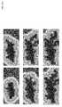
- FIGS. 7A to 11illustrate different visualizations of time-dependent fracture networks and associated gridded volumes and SRVs, according to embodiments of the invention
- FIG. 12is a histogram of microseismic events as a function of time (x-axis) and volume of the SRV (y-axis), according to embodiments of the invention.
- FIG. 13is a schematic illustration of a system according to embodiments of the invention.
- FIG. 14is a flowchart of a method according to embodiments of the invention.
- hydraulic fracturing or other types of blastsmay cause liquid or other material to expand from the blast source to permeate outward expanding through the subsurface.
- the blastrecorded at a plurality of sensor locations, may hit or cause a “microseismic event” to occur at different spatial locations (x,y,z,) at different respective times (t).
- a time-dependent set of events P(x,y,z,t)are recorded, for example, ordered from earlier to later times, and/or from closer to farther distances from the blast source.
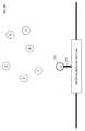
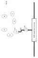
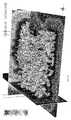
- FIGS. 1A and 1Billustrating a prior art method for determining a fault network or SRV based on a set of microseismic events 101 e.g. P1-P7.
- Microseismic events 101may result from water being pumped from a well treatment interval 105 through the surrounding rock to create a fault or fracture network from which oil may be later pumped or extracted.
- an envelope or boundary 107is created that surrounds the circles and thus encompasses the possible or uncertain paths.
- Envelope 107defines the boundary of a SRV 103 generated based on the group of microseismic events 101 .
- the intervening rockis heterogeneous and liquid will typically flow along those fractures, not homogeneously as shown in FIG. 1B .
- embodiments of the inventionmay use a discrete fracture network approach. Neighboring microseismic events may be connected by an explicit fracture network.
- the fracture network between two subsequent microseismic eventsmay be constructed using local rock material properties, a poisson-based process (e.g., a process that considers the number of microseismic events that have occurred and the time between consecutive events), and percolation-type theory (e.g., examining the flow of a fluid through a group of connected clusters or microseismic events).
- Embodiments of the inventionprovide methods for building and visualizing time-dependent fracture networks (e.g., pipe networks or fracture skeletons) based on micro-seismic events and perforated intervals of wells.
- time-dependent fracture networkse.g., pipe networks or fracture skeletons
- the informationmay be used to calculate fracture intensity, modify secondary permeability fields inside the flow simulation grids for input to a reservoir simulator, for example, to estimate future production volumes of hydrocarbons.
- new fracture network attributessuch as, a distance to perforated intervals of wells, may be determined.
- the fracture networks and their attributesmay be transferred to a visualization of gridded volumes. An evolution through time of a fracture network propagating from a well interval through a reservoir volume may also be visualized.
- time-dependent fracture networksmay be based on the location and time of micro-seismic events and perforated intervals of wells or other sources representing or affecting a fracture skeleton.
- a set of M micro-seismic events P(x, y, z, t)(e.g., measured or recorded by geophones) may be defined where (x,y,z) is the spatial location and (t) is the time at which the event occurs or is recorded.
- Microseismic eventsmay have additional attributes (properties) denoted by a_i.
- the steps for building the fracture network of connected polylinesmay be for example as follows (other steps, combinations of steps, or ordering of steps may be possible):
- the above processmay be performed in real time when each new microseismic event Pi is recorded or processed since the above process inputs only the location (x,y,z) and time (ti) of each event.
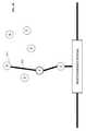
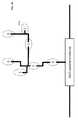
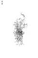
- FIGS. 2A to 2Iare schematic illustrations of a time-dependent fracture network N of microseismic events 202 (e.g. P1-P7) connected by “event-to-event” fractures, according to embodiments of the invention.
- network Nmay be initiated as N(0) including an initial well event P0 205 that occurred at initial time t0.
- Network Nmay grow by adding successive events P1-P7 202 in chronological order of when the events were recorded at t1-t7, respectively.
- Each successive event Pi recorded at time timay be added to a previous existing network N(i ⁇ 1) to generate an expanded network N(i).
- a path or fracturemay also be added connecting each new event Pi to the network N.
- FIGS. 2A to 2Ishow “event-to-event” fractures, e.g., defined by a connection criterion (3i), in which each new event Pi is connected to another network event Pj recorded at an earlier time tj ⁇ ti.
- each ith microseismic event Pimay be connected to one of the subgroup of previously recorded events Pj (including the initial well event P0 205 ).
- the network N(i ⁇ 1)is expanded to N(i).
- Network N(0)may initially include well treatment interval P0 205 recorded at time t0.
- Events P1 through P7may be ordered in a set of events M according to the time that they were recorded or measured at t1-t7, respectively.
- P1 202 a recorded at time t1may be ordered before P2 202 b recorded at t2
- P2 202 b recorded at time t2may be ordered before P3 202 c recorded at t3, etc.
- each microseismic event Pimay occur at a particular location (x,y,z) away from a well treatment interval P0 205 .
- a first microseismic event P1 202 a recorded at time t1may be added to the existing network N(0). Since well treatment interval P0 205 is the only event in the existing network N(0) of events which occurred previous to event P1, a fracture or pipe 204 a may be created, e.g., as a straight line or flat (vertical or tilted) surface along the shortest path, between P1 202 a and the well treatment interval P0 205 . P1 may be added to the network set N(1) (including P1 202 a , fracture 204 a and well treatment interval P0 205 ) and removed from set of candidate events M.
- subsequently recorded event P2 202 bmay be added to the network N.
- event P2 202 b recorded at time t2may be connected to earlier recorded events in the existing network N(1), which includes event P1 202 a recorded at time t1 or well treatment interval P0 205 occurring or recorded at time t0.
- the earlier recorded eventis selected that is closest to the new event P2 202 b .
- event P1 202 ais closer to P2 202 b than is well treatment interval P0 205 .
- a fracture 204 b defining the “event-to-event” connectionmay be added to the network N to connect new event P2 202 b to the closest existing network event recorded at a previous time, e.g. P1 202 a in the example shown in FIG. 2C .
- network N(1)is expanded to network N(2), which includes P1 202 a , P2 202 b , and their respective connecting fractures 204 a and 204 b.
- event P3 202 c recorded at the next subsequent time t3may be added to the network N to generate N(3) in a manner similar to the process described in reference to FIG. 2C .
- event P4 202 d recorded at the next subsequent time t4may be added to the network N to generate network N(4).
- the “event-to-event” connection criterionrequires that an ith microseismic event Pi be connected to the closest one of the previously recorded events P0, . . . , P(i ⁇ 1) in the existing network N(i ⁇ 1).
- the closest previously recorded event to P4 202 dis P2 202 b (since P3 202 c is farther away from P4 202 d ).
- the set of events Pi chronologically ordered in timemay be connected in a non-chronological (out of time) order, such that, each successive event may be connected, not to an immediately preceding and immediately succeeding time event, but may skip events in time to connect to an event recorded further in the past and/or further in the future.
- event P5 202 e recorded at the next subsequent time t5may be added to the network N to generate network N(5).
- the previously recorded event in existing network N(4) closest to new event P5 202 e (based on the connection criterion)is event P2 202 b .
- the networkmay be expanded to N(5) by adding event P5 202 e connected to P2 202 b via fracture 204 e.
- events P6 and P7may be sequentially added to the network N, according to the “event-to-event” connection criterion, in the manner described above.
- a branch index of network Nmay be determined.
- the branch index of the initial branch joining the first event P1 to well treatment interval P0 205is initialized e.g. to zero. Any fractures or events along a single path have the same branch index (i). However, when a path splits at a fork into two or more branches, the branch index of each split path or branch is incremented by one (i+1) greater than the branch index (i) of the parent path or branch.
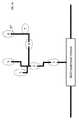
- FIGS. 3A to 3Hschematically illustrate a time-dependent fracture network N of microseismic events (e.g. P1-P7) connected by “event-to-network” fractures, according to embodiments of the invention.
- Event-to-network connectionse.g., defined by a connection criterion (3ii), connects each new ith event Pi to any closest point of the entire previous existing network N(i ⁇ 1), including both events as well as connection pipes or fractures.
- the initial network N(0)may initially be set to include only well treatment interval P0 305 or another source point.
- the first microseismic candidate P1 302 amay be added to the network N, connected by fracture 304 a , to the only (and closest) event in the existing network N(0), the well treatment interval P0 305 .
- FIGS. 3B and 3Cillustrate the generation of networks N(1) and N(2), respectively.
- event P2 302 bis added to the network by connection 304 b to event P1
- event P3 302 cis added to the network by connection 304 c to event P2.
- the “event-to-network” connectionsare equivalent to the “event-to-event” connections ( 204 b and 204 c of FIGS. 2C and 2D ).
- “event-to-network” connectionsdiffer from “event-to-event” connections in other cases e.g. as shown in FIGS. 3D, 3E and 3G .
- network N(4)is generated by adding event P4 302 d recorded at the next subsequent time t4.
- the closest connection between microseismic event P4 302 d and the existing network N(3)is, in the example shown in FIG. 3D , a fracture 304 d that is perpendicular to the existing fracture 304 c and connected to P4 302 d.
- event P5 302 e recorded at the next subsequent time t5may be added to the network to generate network N(5).
- the closest connection between event P5 302 e and the existing network N(4)is, in the example shown in FIG. 3E , a fracture 304 e that is perpendicular to the existing fracture 304 c and connected to event P5 302 e.
- FIGS. 3F and 3Grespectively illustrate the addition of event P6 302 f to generate N(6) and event P7 302 g to generate N(7).
- a branch index of network Nmay be determined.
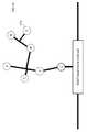
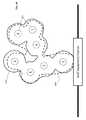
- FIGS. 4A to 4Hschematically illustrate a time-dependent fracture network of microseismic events connected by (e.g. “anisotropic”) fractures in accordance with a connection attribute (e.g. an “anisotropism” attribute), according to embodiments of the invention.
- the example of anisotropic fractures shown in FIGS. 4A to 4Hare of the “event-to-network” connection type, although this discussion of connection attributes also relates to the “event-to-event” connection type.
- Each microseismic event Pmay be associated with a connection attribute (a) defining the connection or fracture between events and the network.
- the attributeis an anisotropism attribute that defines the orientation of anisotropic fracture connections. These attributes may affect the shape, orientation or other characteristics of fracture paths created in the fracture network. Other attributes may include magnitude of the microseismic event, e.g. measured according to the Richter scale, or physical rock properties.
- network N(0)may be initialized to include well treatment interval P0 405 .
- Microseismic events P1-P7may be associated with anisotropic connection attributes defining the orientations of connections to the events, for example, as in a vertical direction 403 a or horizontal direction 403 b.
- microseismic event P1 402 a recorded at time t1may be added to generate network N(1).
- Event P1 402 amay connect to the network by a vertical fracture 404 a that follows the vertical anisotropy of the attribute associated with connecting event P1 402 a.
- microseismic event P2 402 b recorded at time t2may be added to generate network N(2).
- Event P2 402 bmay connect to the network by a fracture 404 b that follows or aligns with the vertical anisotropy of events P1 402 a and P2 402 b . Since P1 402 a and P2 402 b may be slightly offset from each other horizontally (as shown in FIG. 4C ), fracture 404 a may connect horizontally at a point between P1 402 a and P2 402 b . In other examples, fracture 404 a may connect diagonally between P1 402 and P2 402 b , depending on a defined connection criterion or microseismic event attribute, or both.
- microseismic event P3 402 c recorded at time t3may be added to generate network N(3), e.g. in a manner similar to the process described in reference to FIG. 4C .
- microseismic event P4 402 dmay have an attribute describing a horizontal anisotropy. Based on this attribute and the connection criterion that requires a shortest connection between a microseismic event candidate and a fracture network, fracture may horizontally connect event P4 402 d to the existing network.
- microseismic event P5 402 emay have an attribute describing a vertical anisotropy.
- the shortest connection path from event P5 402 e to the existing network N(4)may be vertical in the vicinity of P5 402 e with a horizontal fracture 404 c connecting it to the network.
- FIGS. 4G and 4Hrespectively illustrate the addition of event P6 402 f to generate network N(6) and event P7 402 g to generate network N(7).
- FIG. 5is a compilation of time-dependent fracture networks modeled using “event-to-event” fractures (as described in reference to FIGS. 2A-2I ), “event-to-network” fractures (as described in reference to FIGS. 3A-3H ), and “anisotropic path” fractures (as described in reference to FIGS. 4A-4H ), according to embodiments of the invention.
- Event-to-eventfractures
- FIGS. 3A-3H“event-to-network” fractures
- anisotropic path” fracturesas described in reference to FIGS. 4A-4H
- FIG. 6Ais a schematic illustration of a Stimulated Rock Volume generated from a time-dependent fracture network, according to embodiments of the invention.
- a SRVmay be created by generating points of equal distance 603 from a fracture network 604 .
- the shape connecting the pointsmay be the SRV 608 of fracture network 604 .
- the time-dependent fracture network used in the example shown in FIG. 6Ais the “event-to-network” model from FIG. 3H , although the “event-to-event” or “anisotropic” models from FIG. 2I or 4H , respectively, may also be used.
- FIG. 6Bis a schematic illustration of a comparison between the Stimulated Rock Volume generated according to embodiments of the invention in FIG. 6A (illustrated by the dashed boundary 608 ) and the Stimulated Rock Volume generated according to prior art methods from FIG. 1B (illustrated by the solid boundary 610 ).
- FIG. 6Billustrates how SRVs generated from the same microseismic events 602 P1-P7, yet based on a homogeneous model in FIG. 1B or a heterogeneous model in FIG. 6A , may be different.
- SRV 610 generated as shown in FIG. 1Bis a surface forming an equally spaced envelope around microseismic events 602 . Whereas SRV 608 is generated based on its distance from the entire network including both events and fractures, conventional SRV 610 is generated based only on events but not on any connections or fractures.
- SRV 608 generated based on the fracture networkmay have advantages over SRV 610 generated based only on the events according to prior art methods. For example, accounting for fractures more accurately represents the realistic path of liquid through the subsurface and thus the drainage of the connected well. Further, SRV 608 generated based on the fracture network may be more conservatively sized (e.g. in some cases, smaller) than conventional isotropic SRV 610 , thus avoiding overestimating the reach of each well forming “blind-spot” or missing regions of rock that will not be drained. Further overestimation may occur when using a convex hull to generate an envelope around the set of events, forming an SRV 610 including regions with no drainage to the well. In addition to overestimating, SRV 608 may also avoid underestimating drainage as compared to SRV 610 , which may occur, for example, when smaller circles are used to generate SRV 610 forming disconnected or discrete volumes.
- Fracture network displaysmay indicate the time or time range at which each event and/or fracture occurred, for example, to visualize the well drainage through the network including areas of fast drainage and areas of slow or poor drainage.
- the events and fracturesmay be displayed using color, shading, dimming, and/or scaling to indicate the time at which each event was recorded and/or the predicted time of each fracture interpolated therefrom and/or other attributes.
- the time at which each event in the fracture network was recordedmay be visualized by adding a microseismic event recorded at a time (ti), iterated over all the times of the microseismic events (t1-tn).
- a subset of fractures and/or events in the networkmay be displayed, e.g., including events associated with a specific time step (e.g. every one hour) or time interval (a sub-interval ti of the full recorded time tn, ti ⁇ tn), e.g. one hour.
- Network subsetsmay be displayed separately or together.
- the time interval displayedmay have a fixed or variable duration that may be adjusted e.g. by sliding a tab on a graphical user interface.
- a network subsetmay be displayed including a specified number of active fractures that are a subset of the total number of fractures in the fracture network (e.g. the first or last 100 fractures modelled). Attributes may be computed such as dip lines and azimuth. These attributes may be used for the simulation of the fracture network, which is then used to run a flow simulation and generate an SRV.
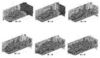
- FIG. 7Aincludes six images of a time dependent fracture network in which color or shading indicates a distance from/to a source points, e.g. the well perforation interval, as measured along a fracture path, according to embodiments of the invention.
- Each of the six imagesrepresents the growth of the fracture network after the passage of a subsequent time interval (e.g. 30 minutes) illustrating the fracture growth every periodic interval of time (e.g. 30 minutes).
- Colors or shadingmay indicate a distance traveled from/to the source points.
- Further processingmay be done by filtering the network based on attributes values (e.g., magnitude or rock types in the vicinity of microseismic events). Visualization of the time dependency may provide geoscientists with a better understanding of fracture propagation through the subsurface.
- FIG. 7Bschematically illustrates a fracture network in three-dimensions
- FIG. 7Cschematically illustrates microseismic events, a distance field and an associated stimulated rock volume computed as an iso-surface from the fracture network of FIG. 7B .
- FIG. 8schematically illustrates a fracture network having a “distance to well perforation” attribute map, for example, to better visualize the effect of hydraulic stimulation.
- This “distance to well perforation” attributemay be correlated to an “energy of the stimulation” attribute, which may indicate a percentage of the blast or stimulation left undetected (e.g. if there is more energy input into the stimulation than output as detected by the geophones).
- the “distance to well perforation” or “energy of the stimulation” attributesmay be measured at the events and interpolated there between to generate a continuous attribute model.
- a fracture networkalso referred to as a “fracture skeleton” and its attributes (e.g. fracture length, stress, magnitude, anistropism, time, branch rank, distance to seed, event density per cell, number of fractures per cell, etc.) may be transferred to a gridded volume or mesh.
- the gridded volumemay be built based on a set of microseismic events M or, in real-time, as each microseismic event in M is recorded, received or analyzed.
- the resolution of the gridded volume(e.g., a number of cells per volume) may be selected, e.g., to provide sufficient precision to achieve the desired volume computations. Attributes of each cell of a gridded volume may be initialized to 0.
- grid cells intersected by fracturesmay be marked as “stimulated” (part of the stimulated rock volume). Attributes of the fractures may be transferred to the gridded volume.
- a gridded volume with marked cellsmay include a time attribute field that corresponds to the time of the event or stimulation.
- the subset of marked cellsmay be a cell-based volume encompassing the fracture network at the grid resolution.
- the gridded volumemay be visualized in real-time (highlighting each cell as a fault therein is stimulated) or after the entire model is built e.g. by selecting different sub-network N(i) associated with a selected time ti of stimulation.
- FIG. 9Aschematically illustrates a time-dependent gridded volume of a fracture network, according to embodiments of the invention.
- FIG. 9Bschematically illustrates a time-dependent fracture network at the resolution of the gridded volume, according to embodiments of the invention.
- the fracture networkis shaded based on its distance from a source point, such as, a well or perforation interval, as measured along the fracture path.
- FIG. 10Aschematically illustrates a time dependent distance field of a fracture network, according to embodiments of the invention.
- FIG. 10Bschematically illustrates the distance field of FIG. 10A along with the fracture network, according to embodiments of the invention.
- Distance fields and volumes associated with the fracture networkmay be generated which characterize the connected fractures volume and may indicate where potential hydrocarbon recovery may occur.
- the distance fieldmay be computed using Euclidian distance to measure the distance from each point of the model to the closest point of the fracture network. These values may be computed and stored for every time step ti.
- FIG. 11schematically illustrates three dimensional images of a SRV expanding with an incrementally growing fracture network, according to embodiments of the invention.
- the SRVmay be an iso-surface, e.g. a surface where each point on the surface has a specific and constant distance from the closest event or fracture in the fracture network.
- the iso-surfaces of the networkmay be determined based on a distance field, which is computed as the Euclidean distance between every point in space and the nearest point on the fracture network.
- the distance fieldmay be colored or shaded, where each color or shade is associated with a particular distance from the fracture network.
- iso-surfacesmay be determined and displayed based on points in the distance field having the same distance from the fracture network.
- the iso-surfacesmay evolve as a function of time, showing the evolution of the Stimulated Rock Volume as the network expands as a function of time.
- the volume inside the iso-surfacesmay also be computed as a function of time.
- FIG. 12is a histogram of events 1202 as a function of time (x-axis) and the volume of the SRV (y-axis), according to embodiments of the invention.
- FIG. 12shows a total number of events 1204 recorded over time.
- FIG. 13schematically illustrates a system 100 in accordance with an embodiment of the present invention.
- System 100may include hydraulic fracturing devices, such as, a stimulator 110 and a network of sensors 120 , as well as a computing system 130 and a display 180 .
- Stimulator 110may be a device to stimulate the subsurface, for example, by hydraulic fracturing in which water or other liquids or gasses are pressurized or blasted in one or more wells to erode and expand the surrounding rock layer.
- a stimulator 110may be placed at each of a plurality of wells or other subsurface locations.
- a network of sensors 120may be placed at a plurality of discrete positions throughout the subsurface referred to as “sensor locations” to measure “microseismic events” at those locations.
- Sensors 120may record event data including, for example, the location (x,y,z) and/or time (t) of each microseismic event.
- Sensors 120may be connected to computing system 130 , e.g. via wired or wireless connections, and may transfer the event data.
- the event datamay be stored in sensors 120 as for example digital information and transferred to computing system 130 by uploading, copying or transmitting the digital information.
- the event data transfermay occur “on-the-fly,” in real-time (e.g. as the data is being recorded, within a predetermined time interval, or before the final event is recorded), or after the stimulation (after all event are recorded at sensors 120 ).
- Computing system 130may process the received event data to generate a fault network according to embodiments of the invention described herein.
- Computing system 130may include, for example, any suitable processing system, computing system, computing device, processing device, computer, processor, or the like, and may be implemented using any suitable combination of hardware and/or software.
- Computing system 130may include for example one or more processor(s) 140 , memory 150 and software 160 .
- Processor 140may communicate with computing system 130 via wired or wireless command and execution signals.
- Computing system 130 or processor(s) 140may be configured to carry out embodiments of the present invention by, for example being connected to memory 150 and executing instructions or software stored in memory 150
- Memory 150may include cache memory, long term memory such as a hard drive or disk, and/or external memory external to processor 140 , for example, including random access memory (RAM), read only memory (ROM), dynamic RAM (DRAM), synchronous DRAM (SD-RAM), flash memory, volatile memory, non-volatile memory, cache memory, buffer, short term memory unit, long term memory unit, or other suitable memory units or storage units.
- Memory 150may store instructions (e.g., software 160 ) which when executed perform embodiments of the invention, and event data.
- Memorymay store data associated with a set of microseismic events and/or a fracture network, where the data associated with each microseismic event may include a location where, and a time when, the microseismic event was recorded by sensors 120 .
- Event datamay include, for example, raw recorded data collected by sensors 120 , instructions for building or visualizing a SRV and/or gridded model, instructions for generating a fracture network based on the microseismic events, or other instructions or data.
- manipulating geological datasuch as the operations for calculating, forming, refining, aligning, etc., fracture networks, may involve the manipulation of data stored in a memory which represents the corresponding geological structures, locations and timing of microseismic events, physical rock properties, or connection criterions.
- Processor 140may include a local or internal memory, such as a cache memory, for relatively fast access to data, e.g., as compared to memory 150 .
- a local or internal memorysuch as a cache memory
- Input device(s) 165may include a keyboard, pointing device (e.g., mouse, trackball, pen, touch screen), or cursor direction keys, for communicating information and command selections to processor 140 .
- Input device 165may communicate user direction information and command selections to processor 140 .
- a usermay use input device 165 to set or select a connection criterion for the generation of a fracture network, set or select a number of attributes to filter or apply to a set of microseismic events, select a button (e.g., manipulate a pointing device such as a mouse to select an on-screen display of a button or other user interface item) to increment the fracture expansion process one event or time interval (e.g.
- a display or monitor 180may output a visualization or model image of the fracture network, SRVs or gridded models generated according to the user-commanded operations executed by processor 140 .
- Display 180may display data from stimulators 110 , sensors 120 or computing system 130 .
- display 180may display visualizations of a time field of fracture networks, a distance field of fracture networks, or a histogram of microseismic events.
- FIG. 14is a flowchart of a method in accordance with an embodiment of the present invention.
- the method of FIG. 14may be executed, in some embodiments, using the system or components described in reference to FIG. 13 , although other system or components may be used.
- one or more stimulatorse.g. stimulator 110 of FIG. 13
- one or more source locationse.g. in a well treatment interval 205 of FIG. 2A
- a plurality of sensorsplaced at a plurality of sampling points throughout a subsurface region may detect and record the microseismic event data (e.g. event points P1-P7 of FIGS. 2A-2I ) including, for example, the location (x,y,z) and/or time (t) of a microseismic event.
- the microseismic event datae.g. event points P1-P7 of FIGS. 2A-2I
- a processormay receive the (filtered or raw) recorded data associated with a set of microseismic events and an existing fracture network, where the data associated with each microseismic event includes a location where, and a time when, the microseismic event was recorded by the sensors.
- the datamay be received, for example, in real-time or after all of the microseismic event associated with a blast or event are recorded.
- the processormay sequentially add each microseismic event in the set to a fracture network in chronological order of the time when the microseismic event was recorded, wherein each microseismic event is added by connecting the event to the existing fracture network by a fracture according to a connection criterion.
- connection criterionmay be selected from the group consisting of an “event-to-event” connection criterion where each sequentially added event is connected to a previously added event associated with an earlier time, an “event-to-network” connection criterion where each sequentially added event is connected to a previously added event or fracture of the fracture network, and a fracture attribute connection criterion such as an anisotropism connection criterion defining an orientation of the fractures connecting events to the fracture network.
- the processormay generate a stimulated rock volume (e.g. SRV 608 of FIG. 6 ) defined by an iso-surface of points having a constant distance to the fracture network including both microseismic events and fractures connecting the microseismic events according to the connection criterion.
- a stimulated rock volumee.g. SRV 608 of FIG. 6
- a displaymay display the fracture network and/or the stimulated rock volume.
- the displaymay visualize the fracture network and/or the stimulated rock volume restricted to include a subset of microseismic events associated with a sub-interval of time within the total sampled time interval, e.g., a predefined number of seconds, minutes and/or hours specified by a user.
- the displaymay visualize the stimulated rock volume to include a distance field of the fracture network that visualizes the distance of points within the stimulate rock volume to the source point(s).
- the displaymay visualize the fracture network to include a branch index for each fracture or event, where each fracture or event along a single path of the fracture network has the same branch index (i) and each fracture or event split from another fracture or event is incremented by one (i+1) greater than the branch index (i) of the fracture or event from which it is split.
- Other visualizations or displaysmay be used, for example, as shown in FIGS. 7-12 .
- Embodiments of the inventionmay include an article such as a computer or processor readable transitory or non-transitory storage medium, such as for example a memory, a disk drive, or a USB flash memory device encoding, including or storing instructions, e.g., computer-executable instructions, which when executed by a processor or controller, cause the processor or controller to carry out methods disclosed herein.
- Embodiment of the present inventionmay be implemented as a computer implemented method, for example, executed using a processor on a computer.
Landscapes
- Engineering & Computer Science (AREA)
- Remote Sensing (AREA)
- Life Sciences & Earth Sciences (AREA)
- Physics & Mathematics (AREA)
- General Life Sciences & Earth Sciences (AREA)
- Geology (AREA)
- General Physics & Mathematics (AREA)
- Geophysics (AREA)
- Environmental & Geological Engineering (AREA)
- Acoustics & Sound (AREA)
- Mining & Mineral Resources (AREA)
- Geophysics And Detection Of Objects (AREA)
- Fluid Mechanics (AREA)
- Geochemistry & Mineralogy (AREA)
- Management, Administration, Business Operations System, And Electronic Commerce (AREA)
Abstract
Description
- 1. Order the microseismic event candidates P by increasing time t in the set M.
- 2. Define source (seed) points of the network N. When the set M includes well perforations information, the treatment intervals (densified or not), or perforation clusters may be used to define the initial source points. These source points have an associated time t corresponding to the time at which the blast, treatment or perforation operation was started. If the set M does not include well treatment information, the microseismic events occurring first in time may be used to define the initial source points. An attribute defining the distance to the source points may be set to 0 for each of the source points.
- 3. Define a connection criterion d(P,N) between microseismic candidate event P and network N.
- i. An “event-to-event” connection criterion may be the shortest distance between the microseismic event candidate and each of a plurality of other events in the fracture network at time t. With the “event-to-event” criterion, the fracture paths or pipes of the network may connect events to events (e.g. as shown in
FIGS. 2A to 2I ). Thus, the flow of liquid is predicted to flow through the fault network from event to event. - ii. An “event-to-network” connection criterion may be the shortest distance between the microseismic event candidate and the fracture network at time t. With the “event-to-network” criterion, events may connect to the fracture paths themselves between events (e.g. as shown in
FIGS. 3A to 3H ). Thus, the flow of liquid is not limited to flow in a straight line from event to event, but can split from one path to another path between events. - iii. An “anistropism” connection criterion may require the connection path between events to be anisotropic (oriented in a specific direction) at one or more of the events. With the “anistropism” criterion, events may connect to fracture paths oriented in a specific direction (e.g. as shown in
FIGS. 4A to 4H ). - iv. Other connection criterions may include a combination of the event candidate and fracture network attributes (e.g. fracture segment length, stress, magnitude, etc.) or larger global scale attributes, like natural fractures sets orientations in addition to or instead of anistropism
- v. Non connection criterions (filters) may be included as well, based on a combination of the event candidate and fracture networks attributes (maximum distance, minimum elapsed time, geological facies or stratigraphic units, etc.)
- i. An “event-to-event” connection criterion may be the shortest distance between the microseismic event candidate and each of a plurality of other events in the fracture network at time t. With the “event-to-event” criterion, the fracture paths or pipes of the network may connect events to events (e.g. as shown in
- 4. Using ith microseismic event P(x,y,z,ti) in the set M, determine or compute criterion d(P,N) to find connection point c based on network N.
- 5. Create a pipe or fracture path between c and p.
- 6. Compute the distance to the source or seed points to be the distance from the microseismic event candidate P to c+distance from c to the source points.
- 7. Compute the branch index of microseismic events and/or fractures. The branch index may be initialized e.g. to zero, at the source point. Each branch or fork in the fracture path, in which one path splits into two or more, causes the branch index to increment e.g. by one or more.
- 8. Compute attributes ti and a_i, e.g. by interpolation if needed, at connection point c and on fracture. Attribute ti (time) may be used, for example, to display fractures which are recorded within a sub-interval of time of the sampling time interval. Other attributes a_i may be used for further filtering or display. Additional attributes, such as, distance to source point may be used to compute a pseudo-volume of a branch (e.g. given a fracture height and aperture).
- 9. Remove event P from the candidate set M and add the event P to the network set N as defining the fracture network at time ti of candidate point P.
- 10. Increment i to i+1 and repeat step 4-10 until there are no more candidate events P in the set M.
Claims (23)
Priority Applications (2)
| Application Number | Priority Date | Filing Date | Title |
|---|---|---|---|
| US14/485,018US10422923B2 (en) | 2014-03-28 | 2014-09-12 | Systems and methods for modeling fracture networks in reservoir volumes from microseismic events |
| EP15160901.3AEP2924471B1 (en) | 2014-03-28 | 2015-03-25 | Systems and methods for modeling fracture networks in reservoir volumes from microseismic events |
Applications Claiming Priority (2)
| Application Number | Priority Date | Filing Date | Title |
|---|---|---|---|
| US201461971648P | 2014-03-28 | 2014-03-28 | |
| US14/485,018US10422923B2 (en) | 2014-03-28 | 2014-09-12 | Systems and methods for modeling fracture networks in reservoir volumes from microseismic events |
Publications (2)
| Publication Number | Publication Date |
|---|---|
| US20150276979A1 US20150276979A1 (en) | 2015-10-01 |
| US10422923B2true US10422923B2 (en) | 2019-09-24 |
Family
ID=52774135
Family Applications (1)
| Application Number | Title | Priority Date | Filing Date |
|---|---|---|---|
| US14/485,018Active2037-07-01US10422923B2 (en) | 2014-03-28 | 2014-09-12 | Systems and methods for modeling fracture networks in reservoir volumes from microseismic events |
Country Status (2)
| Country | Link |
|---|---|
| US (1) | US10422923B2 (en) |
| EP (1) | EP2924471B1 (en) |
Cited By (1)
| Publication number | Priority date | Publication date | Assignee | Title |
|---|---|---|---|---|
| US20210270997A1 (en)* | 2018-06-20 | 2021-09-02 | Total Se | A method for determination of real subsoil composition |
Families Citing this family (19)
| Publication number | Priority date | Publication date | Assignee | Title |
|---|---|---|---|---|
| US8600708B1 (en) | 2009-06-01 | 2013-12-03 | Paradigm Sciences Ltd. | Systems and processes for building multiple equiprobable coherent geometrical models of the subsurface |
| US8743115B1 (en) | 2009-10-23 | 2014-06-03 | Paradigm Sciences Ltd. | Systems and methods for coordinated editing of seismic data in dual model |
| CA2945467C (en)* | 2014-05-23 | 2019-12-17 | Halliburton Energy Services, Inc. | Enhancing reservoir characterization using real-time srv and fracture evolution parameters |
| WO2016039773A1 (en)* | 2014-09-12 | 2016-03-17 | Halliburton Energy Services, Inc. | Analysis of microseismic supported stimulated reservoir volumes |
| US20180119532A1 (en)* | 2015-07-08 | 2018-05-03 | Halliburton Energy Services, Inc. | Improved fracture matching for completion operations |
| US10466388B2 (en) | 2016-09-07 | 2019-11-05 | Emerson Paradigm Holding Llc | System and method for editing geological models by switching between volume-based models and surface-based structural models augmented with stratigraphic fiber bundles |
| US11365626B2 (en) | 2017-03-01 | 2022-06-21 | Proptester, Inc. | Fluid flow testing apparatus and methods |
| US10612356B2 (en) | 2017-03-01 | 2020-04-07 | Proptester, Inc. | Fracture fluid and proppant transport testing systems and methods of using same |
| US10607043B2 (en) | 2017-09-14 | 2020-03-31 | Saudi Arabian Oil Company | Subsurface reservoir model with 3D natural fractures prediction |
| US12228026B2 (en) | 2017-09-14 | 2025-02-18 | Saudi Arabian Oil Company | Modeling reservoir permeability through estimating natural fracture distribution and properties |
| CN110886599B (en)* | 2018-09-07 | 2021-09-17 | 中国石油化工股份有限公司 | Non-fracturing event identification method and system based on fracture speed |
| US10520644B1 (en) | 2019-01-10 | 2019-12-31 | Emerson Paradigm Holding Llc | Imaging a subsurface geological model at a past intermediate restoration time |
| US11156744B2 (en) | 2019-01-10 | 2021-10-26 | Emerson Paradigm Holding Llc | Imaging a subsurface geological model at a past intermediate restoration time |
| CN110909446B (en)* | 2019-10-16 | 2023-05-26 | 中国石油集团川庆钻探工程有限公司 | Complex seam net reconstruction method based on event point and crack extension double-field coupling |
| WO2021108439A1 (en) | 2019-11-26 | 2021-06-03 | Saudi Arabian Oil Company | Modeling reservoir permeability through estimating natural fracture distribution and properties |
| US11525935B1 (en) | 2021-08-31 | 2022-12-13 | Saudi Arabian Oil Company | Determining hydrogen sulfide (H2S) concentration and distribution in carbonate reservoirs using geomechanical properties |
| US11921250B2 (en) | 2022-03-09 | 2024-03-05 | Saudi Arabian Oil Company | Geo-mechanical based determination of sweet spot intervals for hydraulic fracturing stimulation |
| CN115097517B (en)* | 2022-06-24 | 2023-05-09 | 中国矿业大学 | A Discrete Fracture Network Representation and Risk Prediction Method Based on Spatiotemporal Distribution of Microseismic |
| US12312951B1 (en) | 2024-04-26 | 2025-05-27 | Saudi Arabian Oil Company | Fracture reactivation index (FRI) for seal integrity analysis in carbon capture and storage (CCS) |
Citations (86)
| Publication number | Priority date | Publication date | Assignee | Title |
|---|---|---|---|---|
| US4964099A (en) | 1988-06-10 | 1990-10-16 | Schlumberger Technology Corporation | Method of establishing a stratigraphic model of the subsurface from an acoustic impedance profile and a seismic section |
| US4991095A (en) | 1986-07-25 | 1991-02-05 | Stratamodel, Inc. | Process for three-dimensional mathematical modeling of underground geologic volumes |
| US5465323A (en) | 1989-09-20 | 1995-11-07 | Association Scientifique Pour La Geologie Et De Ses Applications | Method for modelling a surface and device for implementing same |
| US5475589A (en) | 1992-07-08 | 1995-12-12 | Spiral Holding, Ltd. | System for evaluating seismic sequence lithology and property, and for evaluating risk associated with predicting potential hydrocarbon reservoir, seal, trap or source |
| US5586082A (en) | 1995-03-02 | 1996-12-17 | The Trustees Of Columbia University In The City Of New York | Method for identifying subsurface fluid migration and drainage pathways in and among oil and gas reservoirs using 3-D and 4-D seismic imaging |
| US5594807A (en) | 1994-12-22 | 1997-01-14 | Siemens Medical Systems, Inc. | System and method for adaptive filtering of images based on similarity between histograms |
| US5671136A (en) | 1995-12-11 | 1997-09-23 | Willhoit, Jr.; Louis E. | Process for seismic imaging measurement and evaluation of three-dimensional subterranean common-impedance objects |
| US5844799A (en) | 1996-01-26 | 1998-12-01 | Institut Francais Du Petrole | Method for simulating the filling of a sedimentary basin |
| WO1999041676A1 (en) | 1998-02-11 | 1999-08-19 | Analogic Corporation | Computed tomography apparatus and method for classifying objects |
| US5995907A (en) | 1998-02-05 | 1999-11-30 | Geoquest | Seismic signal processing method and apparatus for generating time slice or horizon maps in response to seismic traces and quadrature traces to determine geologic features |
| US6018498A (en) | 1998-09-02 | 2000-01-25 | Phillips Petroleum Company | Automated seismic fault detection and picking |
| RU2145100C1 (en) | 1999-02-16 | 2000-01-27 | Миколаевский Эрнест Юлианович | Method for search, prospecting and exploration of oil-gas pool |
| US6106561A (en) | 1997-06-23 | 2000-08-22 | Schlumberger Technology Corporation | Simulation gridding method and apparatus including a structured areal gridder adapted for use by a reservoir simulator |
| US6138076A (en) | 1996-10-31 | 2000-10-24 | Geoquest, A Division Of Schlumberger | Automatic non-artificially extended fault surface based horizon modeling system |
| US6151555A (en) | 1999-03-09 | 2000-11-21 | Schlumberger Technology Corporation | Seismic signal processing method and apparatus for generating a cube of variance values |
| US6246963B1 (en) | 1999-01-29 | 2001-06-12 | Timothy A. Cross | Method for predicting stratigraphy |
| US6278949B1 (en) | 1998-11-25 | 2001-08-21 | M. Aftab Alam | Method for multi-attribute identification of structure and stratigraphy in a volume of seismic data |
| US20010036294A1 (en) | 2000-04-26 | 2001-11-01 | Elf Exploration Production | Method of chrono-stratigraphic interpretation of a seismic cross section or block |
| US6353577B1 (en) | 1996-09-20 | 2002-03-05 | Jacques Joseph Henri Orban | Seismic sensor units |
| US20020032550A1 (en) | 2000-06-29 | 2002-03-14 | Ward Steven B. | Method for modeling an arbitrary well path in a hydrocarbon reservoir using adaptive meshing |
| US20030023383A1 (en) | 2001-07-20 | 2003-01-30 | Stark Tracy Joseph | System for information extraction from geologic time volumes |
| WO2003050766A2 (en) | 2001-12-10 | 2003-06-19 | Earth Decision Sciences | Method, device and programme for three-dimensional modelling of a geological volume by 3d parametering of the geological domain |
| US6597995B1 (en) | 1999-11-05 | 2003-07-22 | Institut Francais Du Petrole | Method for forming a 3D kinematic deformation model of a sedimentary basin |
| US20030216897A1 (en) | 2002-05-17 | 2003-11-20 | Schlumberger Technology Corporation | Modeling geologic objects in faulted formations |
| US6725174B2 (en) | 2000-08-09 | 2004-04-20 | Shell Oil Company | Edge-preserving enhancement of seismic images by nonlinear anisotropic diffusion |
| US6778909B1 (en) | 2002-10-05 | 2004-08-17 | 3Dgeo Development, Inc. | Seismic data processing systems and methods |
| US6791900B2 (en) | 2002-06-13 | 2004-09-14 | Exxonmobil Upstream Research Company | Method of calculating a throw volume for quantitative fault analysis |
| US6820043B2 (en) | 1998-11-02 | 2004-11-16 | T-Surf Corporation | Modeling continuous properties on discontinuous surfaces |
| US20040260476A1 (en) | 2003-04-10 | 2004-12-23 | Schlumberger Technology Corporation | Extrema classification |
| US20040267454A1 (en) | 2002-12-20 | 2004-12-30 | Didier Granjeon | Modelling method for forming a model simulating multilithologic filling of a sedimentary basin |
| US6847737B1 (en) | 1998-03-13 | 2005-01-25 | University Of Houston System | Methods for performing DAF data filtering and padding |
| US6850845B2 (en) | 2001-07-20 | 2005-02-01 | Tracy Joseph Stark | System for multi-dimensional data analysis |
| US6889142B2 (en) | 2003-05-30 | 2005-05-03 | Pgs Exploration (Uk) Limited | Method of correcting for time shifts in seismic data resulting from azimuthal variation |
| US20050114831A1 (en) | 2001-04-18 | 2005-05-26 | Andres Callegari | Volume body renderer |
| US6904169B2 (en) | 2001-11-13 | 2005-06-07 | Nokia Corporation | Method and system for improving color images |
| CA2455810A1 (en) | 2004-01-23 | 2005-07-23 | Tracy Joseph Stark | System for information extraction from geologic time volumes |
| US20050216197A1 (en) | 2004-03-16 | 2005-09-29 | Mario Zamora | Three-dimensional wellbore visualization system for drilling and completion data |
| US20060004522A1 (en) | 2004-06-21 | 2006-01-05 | Marie-Christine Cacas | Seismic image deformation method for improved interpretation |
| WO2006007466A2 (en) | 2004-07-01 | 2006-01-19 | Exxonmobil Upstream Research Company | Hydrodynamics-based gridding geologic modeling (hydro-gridding) |
| US20060025976A1 (en)* | 2000-06-29 | 2006-02-02 | Object Reservoir, Inc. | Method and system for representing reservoir systems |
| US7024021B2 (en) | 2002-09-26 | 2006-04-04 | Exxonmobil Upstream Research Company | Method for performing stratigraphically-based seed detection in a 3-D seismic data volume |
| US20060122780A1 (en) | 2002-11-09 | 2006-06-08 | Geoenergy, Inc | Method and apparatus for seismic feature extraction |
| US7089166B2 (en) | 2000-04-04 | 2006-08-08 | Conocophillips Company | Method of modeling of faulting and fracturing in the earth |
| US7126340B1 (en) | 2005-09-30 | 2006-10-24 | Saudi Arabian Oil Company | Method to characterize microfractured hydrocarbon reservoirs by artificially induced anisotropy of magnetic susceptibility |
| AU2002329615B2 (en) | 2001-07-20 | 2006-12-07 | Tracy Joseph Stark | System for information extraction from geologic time volumes |
| US7187794B2 (en) | 2001-10-18 | 2007-03-06 | Research Foundation Of State University Of New York | Noise treatment of low-dose computed tomography projections and images |
| US7227983B1 (en) | 2002-05-30 | 2007-06-05 | The Regents Of The University Of California | Automated macromolecular crystal detection system and method |
| US7280918B2 (en) | 2005-08-08 | 2007-10-09 | Knowledge Systems, Inc. | Method and system for combining seismic data and basin modeling |
| WO2008005690A2 (en) | 2006-06-21 | 2008-01-10 | Terraspark Geosciences, L.P. | Interpretation of geologic depositional systems |
| GB2444506A (en) | 2006-12-06 | 2008-06-11 | Schlumberger Holdings | Assigning geological ages to horizon surfaces |
| US7412363B2 (en) | 2001-04-18 | 2008-08-12 | Landmark Graphics Corporation | Volume body renderer |
| US7418149B2 (en) | 2004-07-30 | 2008-08-26 | Algolith Inc. | Apparatus and method for adaptive 3D noise reduction |
| US20080232694A1 (en) | 2007-03-21 | 2008-09-25 | Peter Sulatycke | Fast imaging data classification method and apparatus |
| US7446765B2 (en) | 2003-06-06 | 2008-11-04 | Atlas Elektronik Gmbh | Method for generation of a three-dimensional terrain model with the assistance of object-oriented vector data |
| US20080273421A1 (en) | 2007-03-05 | 2008-11-06 | Zvi Koren | Model-based time-preserving tomography |
| US7480205B2 (en) | 2005-04-20 | 2009-01-20 | Landmark Graphics Corporation | 3D fast fault restoration |
| US20090122060A1 (en) | 2005-03-17 | 2009-05-14 | Algotec Systems Ltd | Bone Segmentation |
| US20090157322A1 (en) | 2007-12-12 | 2009-06-18 | Landmark Graphics Corporation, A Halliburton Company | Systems and Methods For Enhancing a Seismic Data Image |
| US7561992B2 (en) | 2004-04-07 | 2009-07-14 | Earth Decision Sciences | Process, device and package for stochastic simulation of ancient riverbeds or ancient geological structures |
| US7660481B2 (en) | 2005-11-17 | 2010-02-09 | Vital Images, Inc. | Image enhancement using anisotropic noise filtering |
| US7711532B2 (en) | 2004-06-02 | 2010-05-04 | Paradigm France | Method for building a three dimensional cellular partition of a geological domain |
| US20100156920A1 (en) | 2008-12-22 | 2010-06-24 | Electronics And Telecommunications Research Institute | Apparatus and method for synthesizing time-coherent texture |
| US7744534B2 (en) | 2002-06-07 | 2010-06-29 | Verathon Inc. | 3D ultrasound-based instrument for non-invasive measurement of amniotic fluid volume |
| US7844402B2 (en) | 2004-11-24 | 2010-11-30 | Paradigm Geophysical Ltd. | System and method for fault identification |
| US7869954B2 (en) | 2006-02-09 | 2011-01-11 | Schlumberger Technology Corp | Using microseismic data to characterize hydraulic fractures |
| US20110015910A1 (en) | 2009-07-16 | 2011-01-20 | Ran Longmin | Method of generating a hex-dominant mesh of a faulted underground medium |
| US20110054857A1 (en) | 2009-09-03 | 2011-03-03 | Schlumberger Technology Corporation | Gridless geological modeling |
| GB2444167B (en) | 2006-11-27 | 2011-03-09 | Inst Francais Du Petrole | Method for stratigraphic interpretation of seismic images |
| US20110115787A1 (en) | 2008-04-11 | 2011-05-19 | Terraspark Geosciences, Llc | Visulation of geologic features using data representations thereof |
| US20110120702A1 (en) | 2009-11-25 | 2011-05-26 | Halliburton Energy Services, Inc. | Generating probabilistic information on subterranean fractures |
| US7970593B2 (en) | 2007-03-30 | 2011-06-28 | Ifp | Method for gradually modifying lithologic facies proportions of a geological model |
| WO2011077227A2 (en) | 2009-12-21 | 2011-06-30 | Schlumberger Technology B.V. | Identification of reservoir geometry from microseismic event clouds |
| US20120037379A1 (en) | 2010-08-13 | 2012-02-16 | Hilliard Lucas J | System and Method For Providing Data Corresponding To Physical Objects |
| US8150663B2 (en) | 2007-03-30 | 2012-04-03 | Paradigm Geophysical (Luxembourg) S.A.R.L. | Partitioning algorithm for building a stratigraphic grid |
| US8274859B2 (en) | 2010-02-22 | 2012-09-25 | Landmark Graphics Corporation | Systems and methods for modeling 3D geological structures |
| US20120318500A1 (en) | 2011-06-15 | 2012-12-20 | Esg Solutions Inc. | Methods and systems for monitoring and modeling hydraulic fracturing of a reservoir field |
| WO2013028237A1 (en) | 2011-08-23 | 2013-02-28 | Exxonmobil Upstream Research Company | Estimating fracture dimensions from microseismic data |
| US20130204598A1 (en) | 2009-06-01 | 2013-08-08 | Paradigm Sciences Ltd. | Systems and methods for building axes, co-axes and paleo-geographic coordinates related to a stratified geological volume |
| US20130215712A1 (en)* | 2011-03-23 | 2013-08-22 | Global Geophysical Services, Inc. | Method for Assessing the Effectiveness of Modifying Transmissive Networks of Natural Reservoirs |
| US20130231903A1 (en) | 2012-03-02 | 2013-09-05 | Wan-Chiu LI | Systems and methods for generating a geological model honoring horizons and faults |
| US20130262052A1 (en) | 2012-04-03 | 2013-10-03 | Jean-Laurent Mallet | System and method for generating an implicit model of geological horizons |
| US8600708B1 (en) | 2009-06-01 | 2013-12-03 | Paradigm Sciences Ltd. | Systems and processes for building multiple equiprobable coherent geometrical models of the subsurface |
| US20140076543A1 (en) | 2011-03-11 | 2014-03-20 | Schlumberger Technology Corporation | System and method for performing microseismic fracture operations |
| US8711140B1 (en) | 2009-06-01 | 2014-04-29 | Paradigm Sciences Ltd. | Systems and methods for building axes, co-axes and paleo-geographic coordinates related to a stratified geological volume |
| US8743115B1 (en) | 2009-10-23 | 2014-06-03 | Paradigm Sciences Ltd. | Systems and methods for coordinated editing of seismic data in dual model |
| US20140207430A1 (en)* | 2013-01-24 | 2014-07-24 | Schlumberger Technology Corporation | Analysis of surface networks for fluids |
- 2014
- 2014-09-12USUS14/485,018patent/US10422923B2/enactiveActive
- 2015
- 2015-03-25EPEP15160901.3Apatent/EP2924471B1/enactiveActive
Patent Citations (96)
| Publication number | Priority date | Publication date | Assignee | Title |
|---|---|---|---|---|
| US4991095A (en) | 1986-07-25 | 1991-02-05 | Stratamodel, Inc. | Process for three-dimensional mathematical modeling of underground geologic volumes |
| US4964099A (en) | 1988-06-10 | 1990-10-16 | Schlumberger Technology Corporation | Method of establishing a stratigraphic model of the subsurface from an acoustic impedance profile and a seismic section |
| US5465323A (en) | 1989-09-20 | 1995-11-07 | Association Scientifique Pour La Geologie Et De Ses Applications | Method for modelling a surface and device for implementing same |
| US5475589A (en) | 1992-07-08 | 1995-12-12 | Spiral Holding, Ltd. | System for evaluating seismic sequence lithology and property, and for evaluating risk associated with predicting potential hydrocarbon reservoir, seal, trap or source |
| US5594807A (en) | 1994-12-22 | 1997-01-14 | Siemens Medical Systems, Inc. | System and method for adaptive filtering of images based on similarity between histograms |
| US5586082A (en) | 1995-03-02 | 1996-12-17 | The Trustees Of Columbia University In The City Of New York | Method for identifying subsurface fluid migration and drainage pathways in and among oil and gas reservoirs using 3-D and 4-D seismic imaging |
| US5671136A (en) | 1995-12-11 | 1997-09-23 | Willhoit, Jr.; Louis E. | Process for seismic imaging measurement and evaluation of three-dimensional subterranean common-impedance objects |
| US5844799A (en) | 1996-01-26 | 1998-12-01 | Institut Francais Du Petrole | Method for simulating the filling of a sedimentary basin |
| US6353577B1 (en) | 1996-09-20 | 2002-03-05 | Jacques Joseph Henri Orban | Seismic sensor units |
| US6138076A (en) | 1996-10-31 | 2000-10-24 | Geoquest, A Division Of Schlumberger | Automatic non-artificially extended fault surface based horizon modeling system |
| US6106561A (en) | 1997-06-23 | 2000-08-22 | Schlumberger Technology Corporation | Simulation gridding method and apparatus including a structured areal gridder adapted for use by a reservoir simulator |
| US5995907A (en) | 1998-02-05 | 1999-11-30 | Geoquest | Seismic signal processing method and apparatus for generating time slice or horizon maps in response to seismic traces and quadrature traces to determine geologic features |
| WO1999041676A1 (en) | 1998-02-11 | 1999-08-19 | Analogic Corporation | Computed tomography apparatus and method for classifying objects |
| US6847737B1 (en) | 1998-03-13 | 2005-01-25 | University Of Houston System | Methods for performing DAF data filtering and padding |
| US6018498A (en) | 1998-09-02 | 2000-01-25 | Phillips Petroleum Company | Automated seismic fault detection and picking |
| US6820043B2 (en) | 1998-11-02 | 2004-11-16 | T-Surf Corporation | Modeling continuous properties on discontinuous surfaces |
| US6278949B1 (en) | 1998-11-25 | 2001-08-21 | M. Aftab Alam | Method for multi-attribute identification of structure and stratigraphy in a volume of seismic data |
| US6246963B1 (en) | 1999-01-29 | 2001-06-12 | Timothy A. Cross | Method for predicting stratigraphy |
| RU2145100C1 (en) | 1999-02-16 | 2000-01-27 | Миколаевский Эрнест Юлианович | Method for search, prospecting and exploration of oil-gas pool |
| US6151555A (en) | 1999-03-09 | 2000-11-21 | Schlumberger Technology Corporation | Seismic signal processing method and apparatus for generating a cube of variance values |
| US6597995B1 (en) | 1999-11-05 | 2003-07-22 | Institut Francais Du Petrole | Method for forming a 3D kinematic deformation model of a sedimentary basin |
| US7089166B2 (en) | 2000-04-04 | 2006-08-08 | Conocophillips Company | Method of modeling of faulting and fracturing in the earth |
| US6771800B2 (en) | 2000-04-26 | 2004-08-03 | Elf Exploration Production | Method of chrono-stratigraphic interpretation of a seismic cross section or block |
| US20010036294A1 (en) | 2000-04-26 | 2001-11-01 | Elf Exploration Production | Method of chrono-stratigraphic interpretation of a seismic cross section or block |
| US20060025976A1 (en)* | 2000-06-29 | 2006-02-02 | Object Reservoir, Inc. | Method and system for representing reservoir systems |
| US20020032550A1 (en) | 2000-06-29 | 2002-03-14 | Ward Steven B. | Method for modeling an arbitrary well path in a hydrocarbon reservoir using adaptive meshing |
| US6725174B2 (en) | 2000-08-09 | 2004-04-20 | Shell Oil Company | Edge-preserving enhancement of seismic images by nonlinear anisotropic diffusion |
| US20050114831A1 (en) | 2001-04-18 | 2005-05-26 | Andres Callegari | Volume body renderer |
| US7412363B2 (en) | 2001-04-18 | 2008-08-12 | Landmark Graphics Corporation | Volume body renderer |
| AU2002329615B2 (en) | 2001-07-20 | 2006-12-07 | Tracy Joseph Stark | System for information extraction from geologic time volumes |
| WO2003009003A1 (en) | 2001-07-20 | 2003-01-30 | Tracy Joseph Stark | System for utilizing geologic time volumes |
| US20030023383A1 (en) | 2001-07-20 | 2003-01-30 | Stark Tracy Joseph | System for information extraction from geologic time volumes |
| US6850845B2 (en) | 2001-07-20 | 2005-02-01 | Tracy Joseph Stark | System for multi-dimensional data analysis |
| US7187794B2 (en) | 2001-10-18 | 2007-03-06 | Research Foundation Of State University Of New York | Noise treatment of low-dose computed tomography projections and images |
| US6904169B2 (en) | 2001-11-13 | 2005-06-07 | Nokia Corporation | Method and system for improving color images |
| WO2003050766A2 (en) | 2001-12-10 | 2003-06-19 | Earth Decision Sciences | Method, device and programme for three-dimensional modelling of a geological volume by 3d parametering of the geological domain |
| US7523024B2 (en) | 2002-05-17 | 2009-04-21 | Schlumberger Technology Corporation | Modeling geologic objects in faulted formations |
| US20030216897A1 (en) | 2002-05-17 | 2003-11-20 | Schlumberger Technology Corporation | Modeling geologic objects in faulted formations |
| US7227983B1 (en) | 2002-05-30 | 2007-06-05 | The Regents Of The University Of California | Automated macromolecular crystal detection system and method |
| US7744534B2 (en) | 2002-06-07 | 2010-06-29 | Verathon Inc. | 3D ultrasound-based instrument for non-invasive measurement of amniotic fluid volume |
| US6791900B2 (en) | 2002-06-13 | 2004-09-14 | Exxonmobil Upstream Research Company | Method of calculating a throw volume for quantitative fault analysis |
| US7024021B2 (en) | 2002-09-26 | 2006-04-04 | Exxonmobil Upstream Research Company | Method for performing stratigraphically-based seed detection in a 3-D seismic data volume |
| US6778909B1 (en) | 2002-10-05 | 2004-08-17 | 3Dgeo Development, Inc. | Seismic data processing systems and methods |
| US20060122780A1 (en) | 2002-11-09 | 2006-06-08 | Geoenergy, Inc | Method and apparatus for seismic feature extraction |
| US20040267454A1 (en) | 2002-12-20 | 2004-12-30 | Didier Granjeon | Modelling method for forming a model simulating multilithologic filling of a sedimentary basin |
| US7248539B2 (en) | 2003-04-10 | 2007-07-24 | Schlumberger Technology Corporation | Extrema classification |
| US20040260476A1 (en) | 2003-04-10 | 2004-12-23 | Schlumberger Technology Corporation | Extrema classification |
| US6889142B2 (en) | 2003-05-30 | 2005-05-03 | Pgs Exploration (Uk) Limited | Method of correcting for time shifts in seismic data resulting from azimuthal variation |
| US7446765B2 (en) | 2003-06-06 | 2008-11-04 | Atlas Elektronik Gmbh | Method for generation of a three-dimensional terrain model with the assistance of object-oriented vector data |
| CA2455810A1 (en) | 2004-01-23 | 2005-07-23 | Tracy Joseph Stark | System for information extraction from geologic time volumes |
| US20050216197A1 (en) | 2004-03-16 | 2005-09-29 | Mario Zamora | Three-dimensional wellbore visualization system for drilling and completion data |
| US7561992B2 (en) | 2004-04-07 | 2009-07-14 | Earth Decision Sciences | Process, device and package for stochastic simulation of ancient riverbeds or ancient geological structures |
| US7711532B2 (en) | 2004-06-02 | 2010-05-04 | Paradigm France | Method for building a three dimensional cellular partition of a geological domain |
| US20060004522A1 (en) | 2004-06-21 | 2006-01-05 | Marie-Christine Cacas | Seismic image deformation method for improved interpretation |
| US7742875B2 (en) | 2004-07-01 | 2010-06-22 | Exxonmobil Upstream Research Company | Method for geologic modeling through hydrodynamics-based gridding (Hydro-Grids) |
| WO2006007466A2 (en) | 2004-07-01 | 2006-01-19 | Exxonmobil Upstream Research Company | Hydrodynamics-based gridding geologic modeling (hydro-gridding) |
| US7418149B2 (en) | 2004-07-30 | 2008-08-26 | Algolith Inc. | Apparatus and method for adaptive 3D noise reduction |
| US7844402B2 (en) | 2004-11-24 | 2010-11-30 | Paradigm Geophysical Ltd. | System and method for fault identification |
| US20090122060A1 (en) | 2005-03-17 | 2009-05-14 | Algotec Systems Ltd | Bone Segmentation |
| US7480205B2 (en) | 2005-04-20 | 2009-01-20 | Landmark Graphics Corporation | 3D fast fault restoration |
| US7280918B2 (en) | 2005-08-08 | 2007-10-09 | Knowledge Systems, Inc. | Method and system for combining seismic data and basin modeling |
| US7126340B1 (en) | 2005-09-30 | 2006-10-24 | Saudi Arabian Oil Company | Method to characterize microfractured hydrocarbon reservoirs by artificially induced anisotropy of magnetic susceptibility |
| US7660481B2 (en) | 2005-11-17 | 2010-02-09 | Vital Images, Inc. | Image enhancement using anisotropic noise filtering |
| US7869954B2 (en) | 2006-02-09 | 2011-01-11 | Schlumberger Technology Corp | Using microseismic data to characterize hydraulic fractures |
| US20100245347A1 (en) | 2006-06-21 | 2010-09-30 | Terraspark Geosciences, L.P. | Extraction of depositional systems |
| WO2008005690A2 (en) | 2006-06-21 | 2008-01-10 | Terraspark Geosciences, L.P. | Interpretation of geologic depositional systems |
| US20120072116A1 (en) | 2006-06-21 | 2012-03-22 | Terraspark Geosciences, Llc | Extraction of depositional systems |
| US8065088B2 (en) | 2006-06-21 | 2011-11-22 | Terraspark Geosciences, Llc | Extraction of depositional systems |
| US8010294B2 (en) | 2006-06-21 | 2011-08-30 | Terraspark Geosciences, Llc | Extraction of depositional systems |
| GB2444167B (en) | 2006-11-27 | 2011-03-09 | Inst Francais Du Petrole | Method for stratigraphic interpretation of seismic images |
| GB2444506A (en) | 2006-12-06 | 2008-06-11 | Schlumberger Holdings | Assigning geological ages to horizon surfaces |
| US20080273421A1 (en) | 2007-03-05 | 2008-11-06 | Zvi Koren | Model-based time-preserving tomography |
| US20080232694A1 (en) | 2007-03-21 | 2008-09-25 | Peter Sulatycke | Fast imaging data classification method and apparatus |
| US8150663B2 (en) | 2007-03-30 | 2012-04-03 | Paradigm Geophysical (Luxembourg) S.A.R.L. | Partitioning algorithm for building a stratigraphic grid |
| US7970593B2 (en) | 2007-03-30 | 2011-06-28 | Ifp | Method for gradually modifying lithologic facies proportions of a geological model |
| US20090157322A1 (en) | 2007-12-12 | 2009-06-18 | Landmark Graphics Corporation, A Halliburton Company | Systems and Methods For Enhancing a Seismic Data Image |
| US20110115787A1 (en) | 2008-04-11 | 2011-05-19 | Terraspark Geosciences, Llc | Visulation of geologic features using data representations thereof |
| US20100156920A1 (en) | 2008-12-22 | 2010-06-24 | Electronics And Telecommunications Research Institute | Apparatus and method for synthesizing time-coherent texture |
| US8711140B1 (en) | 2009-06-01 | 2014-04-29 | Paradigm Sciences Ltd. | Systems and methods for building axes, co-axes and paleo-geographic coordinates related to a stratified geological volume |
| US8600708B1 (en) | 2009-06-01 | 2013-12-03 | Paradigm Sciences Ltd. | Systems and processes for building multiple equiprobable coherent geometrical models of the subsurface |
| US20130204598A1 (en) | 2009-06-01 | 2013-08-08 | Paradigm Sciences Ltd. | Systems and methods for building axes, co-axes and paleo-geographic coordinates related to a stratified geological volume |
| US20110015910A1 (en) | 2009-07-16 | 2011-01-20 | Ran Longmin | Method of generating a hex-dominant mesh of a faulted underground medium |
| US20110054857A1 (en) | 2009-09-03 | 2011-03-03 | Schlumberger Technology Corporation | Gridless geological modeling |
| US8743115B1 (en) | 2009-10-23 | 2014-06-03 | Paradigm Sciences Ltd. | Systems and methods for coordinated editing of seismic data in dual model |
| US20110120702A1 (en) | 2009-11-25 | 2011-05-26 | Halliburton Energy Services, Inc. | Generating probabilistic information on subterranean fractures |
| WO2011077227A2 (en) | 2009-12-21 | 2011-06-30 | Schlumberger Technology B.V. | Identification of reservoir geometry from microseismic event clouds |
| US20130144532A1 (en) | 2009-12-21 | 2013-06-06 | Schlumberger Technology Corporation | Identification of reservoir geometry from microseismic event clouds |
| US8274859B2 (en) | 2010-02-22 | 2012-09-25 | Landmark Graphics Corporation | Systems and methods for modeling 3D geological structures |
| US20120037379A1 (en) | 2010-08-13 | 2012-02-16 | Hilliard Lucas J | System and Method For Providing Data Corresponding To Physical Objects |
| US20140076543A1 (en) | 2011-03-11 | 2014-03-20 | Schlumberger Technology Corporation | System and method for performing microseismic fracture operations |
| US20130215712A1 (en)* | 2011-03-23 | 2013-08-22 | Global Geophysical Services, Inc. | Method for Assessing the Effectiveness of Modifying Transmissive Networks of Natural Reservoirs |
| US20120318500A1 (en) | 2011-06-15 | 2012-12-20 | Esg Solutions Inc. | Methods and systems for monitoring and modeling hydraulic fracturing of a reservoir field |
| WO2013028237A1 (en) | 2011-08-23 | 2013-02-28 | Exxonmobil Upstream Research Company | Estimating fracture dimensions from microseismic data |
| US20130231903A1 (en) | 2012-03-02 | 2013-09-05 | Wan-Chiu LI | Systems and methods for generating a geological model honoring horizons and faults |
| US20130262052A1 (en) | 2012-04-03 | 2013-10-03 | Jean-Laurent Mallet | System and method for generating an implicit model of geological horizons |
| US20140207430A1 (en)* | 2013-01-24 | 2014-07-24 | Schlumberger Technology Corporation | Analysis of surface networks for fluids |
Non-Patent Citations (122)
| Title |
|---|
| "Geomodeling Releases VisualVoxATTM 6.2 Software-Introducing the Geobody Paintbrush," New Release, Sep. 24, 2007, printed from http://www.geomodeling.com/news_22.htm; on Oct. 5, 2009. |
| "Geomodeling Releases VisualVoxATTM 6.2 Software—Introducing the Geobody Paintbrush," New Release, Sep. 24, 2007, printed from http://www.geomodeling.com/news_22.htm; on Oct. 5, 2009. |
| Bakker, "Image Structure Analysis for Seismic Interpretation," doctoral thesis, publicly defended on Jun. 4, 2002. |
| Carr et al., "Reconstruction and Representation of 3D Objects with Radial Basis Functions," ACM SIGGRAPH 2001, ACM Press New York, Computer Graphics Proceedings, pp. 67-76, 2001 (ISBN 1-58113-374-X). |
| Caumon et al. "Building and Editing a Sealed Geological Model," Mathematical Geology, vol. 36, No. 4, May 2004; pp. 405-424. |
| Caumon et al., "Elements for Stochastic Structural Perturbation of Stratigraphic Models," Proc. Petroleum Geostatistics, Sep. 10-14, 2007. |
| Chiles et al., "Modelling the Geometry of Geological Units and its Uncertainty in 3D From Structural Data: The Potential-Field Method," Orebody Modelling and Strategic Mine Planning, pp. 313-320, Nov. 22-24, 2004. |
| Cignoni et al., "Multiresolution Representation and Visualization of Volume Data," IEEE Transactions on Visualizations and Computer Graphics; 3(4), Oct.-Dec. 1997; pp. 352-369. |
| Claerbout, "Fundamentals of Geophysical Data Processing with Applications to Petroleum Prospecting," Blackwell Scientific Publications, 1985. |
| Clawson et al., "The Value of 3D Seismic Attributes for Illuminating Deep Water Deposits by Seismic Forward Modeling of the Brushy Canyon Formation," 2003 SEG Annual Meeting, Oct. 26-31, 2003, Dallas, Texas (only Abstract submitted). |
| Cotesta, L., Kaiser, P. K., Cai, M., & Vorauer, A. (Jan. 2007). Application of Scientific Visualisation-Stress Control on Permeability Anisotropy in Moderately Fractured Rock. In 1st Canada-US Rock Mechanics Symposium. American Rock Mechanics Association. (Year: 2007).* |
| Cotesta, L., Kaiser, P. K., Cai, M., & Vorauer, A. (Jan. 2007). Application of Scientific Visualisation—Stress Control on Permeability Anisotropy in Moderately Fractured Rock. In 1st Canada-US Rock Mechanics Symposium. American Rock Mechanics Association. (Year: 2007).* |
| Courrioux et al., "3D Volumetric modelling of Cadomian Terranes (Northern Brittany, France): an automatic method using Voronoi diagrams," Tectonophysics 331(1-2), Feb. 2001, pp. 181-196. |
| Cremeens et al., "On Chronostratigraphy, Pedostratigraphy, and Archaeological Context," Soil Science Society of America, 1995. |
| Cuisenaire, "Distance Transformations: Fas Algorthms and Applications to Medical Image Processing," Laboratoire de Telecommunications et Teledetection; Oct. 1999. |
| Davies, "Conditioning Poorly Sampled Gathers for Pre and Post Stack Analysis," Journal of Conference Abstracts, 2002, vol. 7, No. 2, pp. 142-143. |
| De Groot et al., "How to create and use 3D Wheeler transformed seismic volumes," SEG/New Orleans 2006 Annual Meeting, pp. 1038-1042. |
| Dorn, "Chapter 13, Interpreting 3-D Seismic Data," The Leading Edge, Sep. 1998, p. 1261-1272. |
| Dulac, "Advances in chrono-stratigraphic interpretation modeling," First Break, vol. 27, Oct. 2009. |
| Durand-Riard et al., "Balanced restoration of geological volumes with relaxed meshing constraints," Computers and Geosciences, vol. 36, No. 4, pp. 441-452, Nov. 17, 2010. |
| EAGE Daily News, "Paradigm is Redefining Interpretation," 2011 EAGE Conference & Exhibition, May 2011. |
| Egan et al., "Three-Dimensional Modelling and Visualisation in Structural Geology: New Techniques for the Restoration and Balancing of Volumes," Proceedings of GIG Conference on Geological Visualisation-the Intelligent Picture?, British Geological Survey, Oct. 1996. |
| Egan et al., "Three-Dimensional Modelling and Visualisation in Structural Geology: New Techniques for the Restoration and Balancing of Volumes," Proceedings of GIG Conference on Geological Visualisation—the Intelligent Picture?, British Geological Survey, Oct. 1996. |
| Escalona et al., Sequence-stratigraphic analysis of Eocene clastic foreland basin deposits in central Lake Maracaibo using high-resolution well correlation and 3-D seismic data, AAPG Bulletin, vol. 90, No. 4, pp. 581-623 (Apr. 2006) (only Abstract submitted). |
| Extended European Search Report issued by the European Patent Office for Application No. EP 15 16 0901 dated Aug. 28, 2015. |
| Frank et al., "3D-reconstruction of Complex Geological Interfaces from Irregularly Distributed and Noisy Point Data," Computers & Geosciences 33 (2007) 932-943. |
| Frank, "Advanced Visualization and Modeling of Tetrahedral Meshes," Doctorat de l'Institut National Poly technique de Lorraine; pp. 1-140; 2006. |
| Gibbons, "Seismic Applications Overview," Society of Petroleum Engineers, Aug. 2003, 9 pages. |
| GoCAD Suite 2.5 2007 User Guide: Parts 1-12, published Sep. 15, 2007. |
| Harris et al., "Fault Seal Risk Volumes-A New Tool for the Assessment of Reservoir Compartmentalisation" 71st EAGE Conference & Exhibition-Amsterdam, The Netherlands, Jun. 8-11, 2009. |
| Harris et al., "Fault Seal Risk Volumes—A New Tool for the Assessment of Reservoir Compartmentalisation" 71st EAGE Conference & Exhibition—Amsterdam, The Netherlands, Jun. 8-11, 2009. |
| International Search Report issued for PCT International Application No. PCT/IB2004/002030, dated Jan. 25, 2005. |
| Jayr et al., "The Need for a Correct Geological Modelling Support: the Advent of the UVT-Transform," First Break, vol. 26, Oct. 2008, pp. 73-79. |
| Jentzsch et al., "Kinematic subsidence modelling of the Lower Rhine Basin," Netherlands Journal of Geosciences, vol. 81, No. 2, pp. 231-239 (2002). |
| Jones, "Data structures for three-dimensional spatial information systems in geology," Int. J. Geographical Information Systems, 3(1), 1989, pp. 15-30. |
| Labrunye et al., "New 3D flattened space for seismic interpretation," SEG Houston 2009 International Exposition and Annual Meeting, pp. 1132-1136. |
| Ledez, "Modelisation D'Objets Naturals par Formulation Implicite," Ecole Nationale Superieure de Geologie; Oct. 28, 2003; pp. 1-158, see English Abstract. |
| Lee et al., "Pitfalls in Seismic Data Flattening," The Leading Edge, Feb. 2001, pp. 161-164. |
| Lepage, "Generation de Maillages Tridimensionnels Pour la Simulation des Phenomenes Physiques en Geosciences," Ecole National Superieure de Geologie; Oct. 28, 2003; pp. 1-224, see English Abstract. |
| Lessenger et al., "An Inverse Stratigraphic Simulation Model: Is stratigraphic Inversion Possible?" Energy Exploration & Exploitation, vol. 14, No. 6, pp. 627-637 (1996) (only Abstract submitted). |
| Ligtenberg et al., "Sequence Stratigraphic Interpretation in the Wheeler Transformed (Flattened) Seismic Domain," EAGE 68th Conference & Exhibition-Vienna, Austria, Jun. 12-15, 2006. |
| Ligtenberg et al., "Sequence Stratigraphic Interpretation in the Wheeler Transformed (Flattened) Seismic Domain," EAGE 68th Conference & Exhibition—Vienna, Austria, Jun. 12-15, 2006. |
| Liwanag, "Reservoir Characterisation, Introducing geological processes in reservoir models," GEO ExPro Oct. 2005, pp. 28-32. |
| Lixin, "Topological relations embodied in a generalized tri-prism (GTP) model for a 3D geoscience modeling system," Computers & Geosciences 30(4), May 2004, pp. 405-418. |
| Lomask et al., "Flattening Without Picking," Geophysics, vol. 71, No. 4, pp. P13-P20, Jul.-Aug. 2006. |
| Lomask et al., "Flattening Without Picking," Stanford Exploration Project, Report 112, Nov. 11, 2002, pp. 141-150. |
| Lomask et al., "Update on Flattening Without Picking," Stanford Exploration Project, Report 120, May 3, 2005, pp. 137-159. |
| Lomask, "Flattening 3-D Seismic Cubes Without Picking," Jan. 8, 2004. |
| Mallet, "Discrete Smooth Interpolation in Geometric Modelling," Journal of Computer Aided Design, 24(4), 1992, pp. 178-191. |
| Mallet, "Numerical Earth Models," 2008 EAGE Publications, ISBN 978-90-73781-63-4, p. 147-157. |
| Mallet, "Space-time Mathematical Framework for Sedimentary Geology," Journal of Mathematical Geology, vol. 36, No. 1, Jan. 2004, pp. 1-32. |
| Mallet, Geomodeling (Book chapter); Chapter 6; Oxford University Press; cover and preface pages and pp. 244-315, 2002. |
| Mallet, Geomodeling, Oxford University Press, Sep. 22, 2004 (ISBN 0-19-514460.0). |
| Mitchum et al., "Seismic Stratigraphy and Global Changes of Sea Level, Part 6: Stratigraphic Interpretation of Seismic Reflection Patterns in Depositional Sequences," received Jan. 6, 1977, accepted Jun. 13, 1977, pp. 117-133. |
| Monsen et al., "Geological process controlled interpretation based on 3D Wheeler diagram generation," SEG/San Antonio 2007 Annual Meeting, pp. 885-889. |
| Moretti et al., "KINE3D: a New 3D Restoration Method Based on a Mixed Approach Linking Geometry and Geomechanics," Oil & Gas Science and Techonology, Rev. IFP, vol. 61 (2006), No. 2, pp. 277-289. |
| Moyen et al., "3D-Parameterization of the 3D Geological Space-The Geochron Model," 9th European Conference on the Mathematics of Oil Recovery, Geological Modelling I, Aug. 30, 2004. |
| Moyen et al., "3D-Parameterization of the 3D Geological Space—The Geochron Model," 9th European Conference on the Mathematics of Oil Recovery, Geological Modelling I, Aug. 30, 2004. |
| Moyen, "Paramétrisation 3D de L'espace en Géologie Sédimentaire: Le Modèle Geochron Thèse," Doctorat de l'Institut National Polytechnique de Lorraine, Jun. 9, 2005 (original text in French and English translation). |
| Müller et al. "3D Restoration and mechanical properties," from structure.harvard.edu/projects/restoration, Harvard University Structural Geology and Earth Resources Group, 2005, accessed on Aug. 21, 2012. |
| Notice of Allowance issued for U.S. Appl. No. 11/628,559, dated Dec. 24, 2009. |
| Notice of Allowance issued for U.S. Appl. No. 12/791,352 dated Dec. 6, 2013. |
| Notice of Allowance issued for U.S. Appl. No. 12/791,370, dated Jul. 22, 2013. |
| Notice of Allowance issued for U.S. Appl. No. 12/909,981 dated Jan. 27, 2014. |
| Office Action issued for U.S. Appl. No. 11/628,559, dated Jun. 24, 2009. |
| Office Action issued for U.S. Appl. No. 12/791,370, dated Nov. 26, 2012. |
| Office Action issued for U.S. Appl. No. 12/791,483, dated Aug. 17, 2012. |
| Office Action issued for U.S. Appl. No. 12/909,981 dated Aug. 19, 2013. |
| Office Action issued for U.S. Appl. No. 14/059,099, dated Jun. 16, 2014. |
| Office Action issued for U.S. Appl. No. 14/065,713, dated Jun. 19, 2014. |
| Office Action issued for U.S. Appl. No. 14/211,744, dated Jun. 3, 2014. |
| Office Action issued for U.S. Appl. No. 14/260,760, dated Jul. 9, 2014. |
| O'Malley et al., "Towards Robust Structure-Based Enhancement and Horizon Picking in 3-D Seismic Data," Proceedings of the 2004 IEEE Computer Society Conference on Computer Vision and Pattern Recognition (CVPR '04), 2004, vol. 2, pp. 482-489. |
| OpendTect Workflows Documentation version 4.2, dGB Beheer B.V., dGB Earth Sciences, Copyright © 2002-2010. |
| Oyedele, "3-D High Resolution Seismic Imaging of Middle-Late Quaternary Depositional Systems, Southeast Green Canyon, Sigsbee Escarpment, Gulf of Mexico," Thesis presented to the Faculty of the Dept. of Geosciences at the University of Houston, Aug. 2005. |
| Paradigm™ SKUA™ 2009 User Guide: Part V Seismic Interpretation Modeling, Feb. 3, 2009. |
| Rouby et al., "3-D Restoration of Complexly Folded and Faulted Surfaces Using Multiple Unfolding Mechanisms," AAPG Bulletin, vol. 84, No. 6, pp. 805-829 (Jun. 2000). |
| Rumpf et al., "A Continuous Skeletonization Method Based on Level Sets," Joint EUROGRAPHICS-IEEE Symposium on Visualization, pp. 151-157 (2002). |
| Rumpf et al., "A Continuous Skeletonization Method Based on Level Sets," Joint EUROGRAPHICS—IEEE Symposium on Visualization, pp. 151-157 (2002). |
| Saito, "New Algorithms for Euclidean Distance Transformation of an n-Dimensional Digitized Picture with Applications," Pattern Recognition, 27(11) 1994; pp. 1551-1565. |
| Samson et al., "Quantifying the Impact of Structural Uncertainties on Gross-Rock Volume Estimates", SPE 1996, pp. 381-392. |
| Smith et al., "SUSAN-A New Approach to Low Level Image Processing," International Journal of Computer Vision, 1997, vol. 23, Iss. 1, pp. 45-78. |
| Smith et al., "SUSAN—A New Approach to Low Level Image Processing," International Journal of Computer Vision, 1997, vol. 23, Iss. 1, pp. 45-78. |
| Souche, "Integration of fault models into unstructured grids and geo-chronological space," 24th GOCAD Meeting, Jun. 2004. |
| Stark, "Generation of a 3D seismic 'Wheeler Diagram' from a high resolution Age Volume," pp. 782-786, submitted to the 75th Annual SEG Convention, Nov. 6-11, 2005, Houston, TX. |
| Stark, "Relative Geologic Time (Age) Volumes-Relating Every Seismic Sample to a Geologically Reasonable Horizon," The Leading Edge, Sep. 2004, pp. 928-932. |
| Stark, "Generation of a 3D seismic ‘Wheeler Diagram’ from a high resolution Age Volume," pp. 782-786, submitted to the 75th Annual SEG Convention, Nov. 6-11, 2005, Houston, TX. |
| Stark, "Relative Geologic Time (Age) Volumes—Relating Every Seismic Sample to a Geologically Reasonable Horizon," The Leading Edge, Sep. 2004, pp. 928-932. |
| Svensson, U. (2001). A continuum representation of fracture networks. Part I: Method and basic test cases. Journal of Hydrology, 250(1-4), 170-186. (Year: 2001).* |
| Terraspark Geosciences, "Geoscience Interpretation Visualization Consortium (GIVC)," http://terraspark.com/GIVC.consort, accessed on May 11, 2006. |
| Tertois et al., "Editing faults within tetrahedral volume models in real time," In Jolley, S.J., Barr, D., Walsh, J.J. et al. (Eds), Structurally Complex Reservoirs, London, UK: Geological Society of London, Special Publications 2007; v. 292; p. 89-101 (doi: 10.1144/SP292.5). |
| Tertois et al., Real-time Tetrahedral Volume Editing Accounting for Discontinuities; Ninth International Conference on Computer Aided Design and Computer Graphics (CAD/CG 2005) 2005 IEEE; pp. 1-6). |
| Tertois, "Création et édition de modèles géologiques par Champs de potential: Application au modele GeoChron-Thèse," Institut National Polytechnique de Lorraine, Jun. 21, 2007. |
| Tertois, "Création et édition de modèles géologiques par Champs de potential: Application au modele GeoChron—Thèse," Institut National Polytechnique de Lorraine, Jun. 21, 2007. |
| Tertois, Preserving Geological Information During Real-Time Editing of Faults in Tetrahedral Models; Int. Assoc. for Mathematic Geology Xith International Congress Universite de Liege-Belgium; 2006; S14-24; pp. 1-4. |
| Tertois, Preserving Geological Information During Real-Time Editing of Faults in Tetrahedral Models; Int. Assoc. for Mathematic Geology Xith International Congress Universite de Liege—Belgium; 2006; S14-24; pp. 1-4. |
| Thomsen et al., "Towards a balanced 3D Kinematic Model of a Faulted Domain-the Bergheim Open Pit Mine, Lower Rhine Basin," Netherlands Journal of Geoscience, vol. 81, No. 2, pp. 241-250 (2002). |
| Thomsen et al., "Towards a balanced 3D Kinematic Model of a Faulted Domain—the Bergheim Open Pit Mine, Lower Rhine Basin," Netherlands Journal of Geoscience, vol. 81, No. 2, pp. 241-250 (2002). |
| Thore et al., Integration of Structural Uncertainties into Reservoir grids construction-70th EAGE Conference & Exhibition-Rome, Italy, Jun. 9-12, 2008. |
| Thore et al., Integration of Structural Uncertainties into Reservoir grids construction—70th EAGE Conference & Exhibition—Rome, Italy, Jun. 9-12, 2008. |
| Trudgill et al., "Integrating 3D Seismic Data with Structural Restorations to Elucidate the Evolution of a Stepped Counter-Regional Salt System, Eastern Louisiana Shelf, Northern Gulf of Mexico," pp. 165-176. (2004). |
| U.S. Appl. No. 13/862,680, filed Apr. 15, 2013, Tertois, et al. |
| U.S. Appl. No. 14/059,099, filed Oct. 21, 2013, Mallet et al. |
| U.S. Appl. No. 14/065,713, filed Oct. 29, 2013, Mallet et al. |
| U.S. Appl. No. 14/189,505, filed Feb. 25, 2014, Mallet. |
| U.S. Appl. No. 14/211,744, filed Mar. 14, 2014, Mallet. |
| U.S. Appl. No. 14/260,760, filed Apr. 24, 2014, Mallet, et al. |
| U.S. Appl. No. 61/896,760, filed Oct. 29, 2013, Dulac, et al. |
| Urbancic, T., & Baig, A. (Feb. 2014). Enhancing recovery in shales through stimulation of pre-existing fracture networks. In SPE Hydraulic Fracturing Technology Conference. Society of Petroleum Engineers. (Year: 2014).* |
| Wen et al., "Use of Border Regions for Improved Permeability Upscaling," Mathematical Geology, 35(5), Jul. 2003; pp. 521-547. |
| Wood et al., "Applying Sequence Stratigraphy and Seismic Stratal Slice Technology in the Gulf of Mexico," GASTIPS, Lang et al. (Eds.), Winter 2003, vol. 9, No. 1, pp. 10-21. |
| Zeng et al., "Interpretive Advantages of 90 Degree-Phase Wavelets: Part 2-Seismic Applications," Geophysics, SEG, vol. 70, No. 3, May 2005-Jun. 2005. pp. C-17-C-24. |
| Zeng et al., "Seismic Frequency Control on Carbonate Seismic Stratigraphy: A Case Study of the Kingdom Abo Sequence, West Texas," AAPG Bulletin, vol. 87, Issue No. 2, pp. 273-293 (2003) (only Abstract submitted). |
| Zeng et al., "Stratal Slicing and Seismic Facies Imaging," Bureau of Economic Geology, The University of Texas at Austin, 1998. (only Abstract submitted). |
| Zeng et al., "Stratal Slicing of Miocene-Pliocene Sediments in Vermilion Block 50-Tiger Shoal Area, Offshore Louisiana," The Leading Edge, Offshore Technology Special Section, vol. 20, No. 4, Apr. 2001, pp. 408-418. |
| Zeng et al., "Stratal Slicing, Part I: Realistic 3-D Seismic Model," Geophysics, Seg, vol. 63, No. 2, Mar. 1998-Apr. 1998, pp. 502-513. |
| Zeng et al., "Stratal Slicing, Part II: Read 3-D Seismic Data," Geophysics, vol. 63, No. 2 (Mar.-Apr. 1998); pp. 514-522. |
| Zeng et al., "Three-D Seismic Facies Imaging by Stratal Slicing of Miocene-Pliocene Sediments in Vermilion Block 50-Tiger Shoal Area, Offshore Louisiana," Secondary Gas Recovery, AAPG 2000. |
| Zeng et al., "Interpretive Advantages of 90 Degree-Phase Wavelets: Part 2—Seismic Applications," Geophysics, SEG, vol. 70, No. 3, May 2005-Jun. 2005. pp. C-17-C-24. |
| Zeng et al., High-frequency Sequence Stratigraphy from Seismic Sedimentology: Applied to Miocene, Vermilion Block 50, Tiget Shoal Area Offshoure Louisiana, AAPG Bulletin, Feb. 2004, vol. 88, No. 2, pp. 153-174 (only Abstract submitted). |
| Zeng, "From Seismic Stratigraphy to Seismic Sedimentology: A Sensible Transition," GCAGS Transactions, vol. 51, pp. 413-420 (2001) (only Abstract submitted). |
| Zeng,"Stratal Slicing: Benefits and Challenges," The Leading Edge 29, 1040 (Sep. 2010). |
Cited By (2)
| Publication number | Priority date | Publication date | Assignee | Title |
|---|---|---|---|---|
| US20210270997A1 (en)* | 2018-06-20 | 2021-09-02 | Total Se | A method for determination of real subsoil composition |
| US12298465B2 (en)* | 2018-06-20 | 2025-05-13 | Totalenergies Onetech | Method for determination of real subsoil composition |
Also Published As
| Publication number | Publication date |
|---|---|
| EP2924471A1 (en) | 2015-09-30 |
| EP2924471B1 (en) | 2018-07-04 |
| US20150276979A1 (en) | 2015-10-01 |
Similar Documents
| Publication | Publication Date | Title |
|---|---|---|
| US10422923B2 (en) | Systems and methods for modeling fracture networks in reservoir volumes from microseismic events | |
| EP3455654B1 (en) | Three-dimensional fracture abundance evaluation of subsurface formation based on geomechanical simulation of mechanical properties thereof | |
| US20190138672A1 (en) | System and method for characterizing uncertainty in subterranean reservoir fracture networks | |
| CA2815906C (en) | Identifying reservoir drainage patterns from microseismic data | |
| CA2861536C (en) | Systems and methods for selecting facies model realizations | |
| CN109100790B (en) | Artificial crack simulation method and device | |
| WO2015178931A1 (en) | Enhancing reservoir characterization using real-time srv and fracture evolution parameters | |
| EP3455459B1 (en) | Three-dimensional fracture abundance evaluation of subsurface formations | |
| CN114429057B (en) | Natural fracture modeling and fracturing simulation method, device, computer and storage medium | |
| WO2015050530A1 (en) | In-situ wellbore, core and cuttings information system | |
| Hugot* et al. | Connecting the dots: Microseismic-derived connectivity for estimating reservoir volumes in low-permeability reservoirs | |
| US20150032377A1 (en) | System and method for remaining resource mapping | |
| US10650107B2 (en) | Three-dimensional subsurface formation evaluation using projection-based area operations | |
| EP3374970B1 (en) | Fracture network simulation using meshes of different triangle sizes | |
| Baroni et al. | Forecasting production in shale and tight reservoirs: a practical simulation method capturing the complex hydraulic fracturing physics | |
| Hussain et al. | Understanding the true stimulated reservoir volume in shale reservoirs | |
| Rezaei et al. | Applications of Machine Learning for Estimating the Stimulated Reservoir Volume (SRV) | |
| CN111815769A (en) | Modeling method, computing device and storage medium for thrust-driven tectonic belt structure | |
| CN104612660B (en) | MRF-based oil and gas reservoir lithofacies stochastic simulation and achievement method | |
| Bailey et al. | Application of Machine Learning to Create a Discrete Fracture Network Model for Utah FORGE Fracture Injections | |
| Zhang et al. | Development and simulation of complex discrete fracture networks through integration of field data: Application to the Hydraulic Fracturing Test Site in Midland Basin, Texas | |
| Yang et al. | AI-Driven Geology-Engineering Workflow for Hydraulic Fracture Evaluation with GPU Acceleration | |
| CN118837946A (en) | Microseism positioning method, device, equipment and medium | |
| Kabir et al. | Understanding Variable Well Performance in a Chalk Reservoir | |
| Handyside et al. | A practical application of stochastic modeling techniques for turbidite reservoirs |
Legal Events
| Date | Code | Title | Description |
|---|---|---|---|
| AS | Assignment | Owner name:PARADIGM GEOPHYSICAL, CORP., TEXAS Free format text:ASSIGNMENT OF ASSIGNORS INTEREST;ASSIGNORS:HUGOT, ALEXANDRE;DULAC, JEAN-CLAUDE;SIGNING DATES FROM 20140901 TO 20140907;REEL/FRAME:033967/0853 Owner name:PARADIGM SCIENCES LTD., CAYMAN ISLANDS Free format text:ASSIGNMENT OF ASSIGNORS INTEREST;ASSIGNOR:PARADIGM GEOPHYSICAL, CORP.;REEL/FRAME:033967/0842 Effective date:20140910 | |
| AS | Assignment | Owner name:EMERSON PARADIGM HOLDING LLC, TEXAS Free format text:ASSIGNMENT OF ASSIGNORS INTEREST;ASSIGNOR:PARADIGM SCIENCES LTD.;REEL/FRAME:044985/0086 Effective date:20171201 | |
| STPP | Information on status: patent application and granting procedure in general | Free format text:RESPONSE TO NON-FINAL OFFICE ACTION ENTERED AND FORWARDED TO EXAMINER | |
| STPP | Information on status: patent application and granting procedure in general | Free format text:NOTICE OF ALLOWANCE MAILED -- APPLICATION RECEIVED IN OFFICE OF PUBLICATIONS | |
| STPP | Information on status: patent application and granting procedure in general | Free format text:AWAITING TC RESP, ISSUE FEE PAYMENT VERIFIED | |
| FEPP | Fee payment procedure | Free format text:PETITION RELATED TO MAINTENANCE FEES GRANTED (ORIGINAL EVENT CODE: PTGR); ENTITY STATUS OF PATENT OWNER: LARGE ENTITY | |
| STPP | Information on status: patent application and granting procedure in general | Free format text:PUBLICATIONS -- ISSUE FEE PAYMENT VERIFIED | |
| STCF | Information on status: patent grant | Free format text:PATENTED CASE | |
| AS | Assignment | Owner name:JPMORGAN CHASE BANK, N.A., AS ADMINISTRATIVE AGENT, ILLINOIS Free format text:SECURITY INTEREST;ASSIGNORS:ASPENTECH CORPORATION F/K/A ASPEN TECHNOLOGY, INC.;EMERSON PARADIGM HOLDINGS LLC;PARADIGM GEOPHYSICAL CORP.;AND OTHERS;REEL/FRAME:061161/0782 Effective date:20220516 | |
| AS | Assignment | Owner name:ASPEN PARADIGM HOLDING LLC, TEXAS Free format text:CHANGE OF NAME;ASSIGNOR:EMERSON PARADIGM HOLDING LLC;REEL/FRAME:061805/0784 Effective date:20220912 | |
| MAFP | Maintenance fee payment | Free format text:PAYMENT OF MAINTENANCE FEE, 4TH YEAR, LARGE ENTITY (ORIGINAL EVENT CODE: M1551); ENTITY STATUS OF PATENT OWNER: LARGE ENTITY Year of fee payment:4 | |
| AS | Assignment | Owner name:JPMORGAN CHASE BANK, N.A., AS ADMINISTRATIVE AGENT, ILLINOIS Free format text:SECURITY INTEREST;ASSIGNORS:ASPENTECH CORPORATION;ASPEN PARADIGM HOLDING LLC;REEL/FRAME:068424/0341 Effective date:20240627 |