US10420467B2 - Method and system for measuring binocular alignment - Google Patents
Method and system for measuring binocular alignmentDownload PDFInfo
- Publication number
- US10420467B2 US10420467B2US15/696,161US201715696161AUS10420467B2US 10420467 B2US10420467 B2US 10420467B2US 201715696161 AUS201715696161 AUS 201715696161AUS 10420467 B2US10420467 B2US 10420467B2
- Authority
- US
- United States
- Prior art keywords
- eye
- infrared
- stereo display
- images
- image
- Prior art date
- Legal status (The legal status is an assumption and is not a legal conclusion. Google has not performed a legal analysis and makes no representation as to the accuracy of the status listed.)
- Active
Links
- 238000000034methodMethods0.000titleabstractdescription71
- 230000004308accommodationEffects0.000claimsabstractdescription30
- 230000003287optical effectEffects0.000claimsdescription30
- 239000011521glassSubstances0.000claimsdescription16
- 230000002093peripheral effectEffects0.000claimsdescription14
- 230000037361pathwayEffects0.000claimsdescription13
- 238000003331infrared imagingMethods0.000claimsdescription9
- 239000007788liquidSubstances0.000claimsdescription2
- 208000004350StrabismusDiseases0.000abstractdescription77
- 230000002350accommodative effectEffects0.000abstractdescription54
- 210000001508eyeAnatomy0.000description236
- 230000004044responseEffects0.000description26
- 230000000007visual effectEffects0.000description23
- 208000001491myopiaDiseases0.000description17
- 210000000695crystalline lenAnatomy0.000description16
- 230000004438eyesightEffects0.000description16
- 238000012937correctionMethods0.000description13
- 238000012360testing methodMethods0.000description12
- 230000008859changeEffects0.000description10
- 210000004556brainAnatomy0.000description6
- 208000002193PainDiseases0.000description5
- 238000005259measurementMethods0.000description5
- 230000036407painEffects0.000description5
- 208000019695Migraine diseaseDiseases0.000description4
- 238000002474experimental methodMethods0.000description4
- 210000003205muscleAnatomy0.000description4
- 230000008447perceptionEffects0.000description4
- 210000001747pupilAnatomy0.000description4
- 206010013082DiscomfortDiseases0.000description3
- 230000008901benefitEffects0.000description3
- 238000003384imaging methodMethods0.000description3
- 230000006641stabilisationEffects0.000description3
- 238000011105stabilizationMethods0.000description3
- 230000016776visual perceptionEffects0.000description3
- 206010052143Ocular discomfortDiseases0.000description2
- 208000003464asthenopiaDiseases0.000description2
- 210000004087corneaAnatomy0.000description2
- 238000009826distributionMethods0.000description2
- 230000006872improvementEffects0.000description2
- 238000002360preparation methodMethods0.000description2
- 201000010041presbyopiaDiseases0.000description2
- 230000009467reductionEffects0.000description2
- 230000003068static effectEffects0.000description2
- 235000017276SalviaNutrition0.000description1
- 241001072909SalviaSpecies0.000description1
- 230000004075alterationEffects0.000description1
- 238000004458analytical methodMethods0.000description1
- 230000003542behavioural effectEffects0.000description1
- 210000005252bulbus oculiAnatomy0.000description1
- 239000002775capsuleSubstances0.000description1
- 238000012512characterization methodMethods0.000description1
- 238000004040coloringMethods0.000description1
- 230000006866deteriorationEffects0.000description1
- 238000002405diagnostic procedureMethods0.000description1
- 230000026058directional locomotionEffects0.000description1
- 230000000694effectsEffects0.000description1
- 230000003203everyday effectEffects0.000description1
- 230000006870functionEffects0.000description1
- 238000012804iterative processMethods0.000description1
- 238000002372labellingMethods0.000description1
- 239000004973liquid crystal related substanceSubstances0.000description1
- 230000033001locomotionEffects0.000description1
- 230000007246mechanismEffects0.000description1
- 230000005043peripheral visionEffects0.000description1
- 230000010287polarizationEffects0.000description1
- 238000001485positron annihilation lifetime spectroscopyMethods0.000description1
- 238000003825pressingMethods0.000description1
- 230000008569processEffects0.000description1
- 238000012545processingMethods0.000description1
- 230000000750progressive effectEffects0.000description1
- 210000001525retinaAnatomy0.000description1
- 230000009466transformationEffects0.000description1
- 230000007704transitionEffects0.000description1
- 230000004304visual acuityEffects0.000description1
- 210000000857visual cortexAnatomy0.000description1
- 238000005303weighingMethods0.000description1
Images


Classifications
- A—HUMAN NECESSITIES
- A61—MEDICAL OR VETERINARY SCIENCE; HYGIENE
- A61B—DIAGNOSIS; SURGERY; IDENTIFICATION
- A61B3/00—Apparatus for testing the eyes; Instruments for examining the eyes
- A61B3/10—Objective types, i.e. instruments for examining the eyes independent of the patients' perceptions or reactions
- A61B3/14—Arrangements specially adapted for eye photography
- A—HUMAN NECESSITIES
- A61—MEDICAL OR VETERINARY SCIENCE; HYGIENE
- A61B—DIAGNOSIS; SURGERY; IDENTIFICATION
- A61B3/00—Apparatus for testing the eyes; Instruments for examining the eyes
- A61B3/0091—Fixation targets for viewing direction
- A—HUMAN NECESSITIES
- A61—MEDICAL OR VETERINARY SCIENCE; HYGIENE
- A61B—DIAGNOSIS; SURGERY; IDENTIFICATION
- A61B3/00—Apparatus for testing the eyes; Instruments for examining the eyes
- A61B3/02—Subjective types, i.e. testing apparatus requiring the active assistance of the patient
- A61B3/08—Subjective types, i.e. testing apparatus requiring the active assistance of the patient for testing binocular or stereoscopic vision, e.g. strabismus
- A—HUMAN NECESSITIES
- A61—MEDICAL OR VETERINARY SCIENCE; HYGIENE
- A61B—DIAGNOSIS; SURGERY; IDENTIFICATION
- A61B3/00—Apparatus for testing the eyes; Instruments for examining the eyes
- A61B3/02—Subjective types, i.e. testing apparatus requiring the active assistance of the patient
- A61B3/09—Subjective types, i.e. testing apparatus requiring the active assistance of the patient for testing accommodation
- A—HUMAN NECESSITIES
- A61—MEDICAL OR VETERINARY SCIENCE; HYGIENE
- A61B—DIAGNOSIS; SURGERY; IDENTIFICATION
- A61B3/00—Apparatus for testing the eyes; Instruments for examining the eyes
- A61B3/10—Objective types, i.e. instruments for examining the eyes independent of the patients' perceptions or reactions
- A61B3/113—Objective types, i.e. instruments for examining the eyes independent of the patients' perceptions or reactions for determining or recording eye movement
- H—ELECTRICITY
- H04—ELECTRIC COMMUNICATION TECHNIQUE
- H04N—PICTORIAL COMMUNICATION, e.g. TELEVISION
- H04N13/00—Stereoscopic video systems; Multi-view video systems; Details thereof
- H04N13/30—Image reproducers
- H04N13/327—Calibration thereof
- H—ELECTRICITY
- H04—ELECTRIC COMMUNICATION TECHNIQUE
- H04N—PICTORIAL COMMUNICATION, e.g. TELEVISION
- H04N23/00—Cameras or camera modules comprising electronic image sensors; Control thereof
- H04N23/20—Cameras or camera modules comprising electronic image sensors; Control thereof for generating image signals from infrared radiation only
- H—ELECTRICITY
- H04—ELECTRIC COMMUNICATION TECHNIQUE
- H04N—PICTORIAL COMMUNICATION, e.g. TELEVISION
- H04N5/00—Details of television systems
- H04N5/30—Transforming light or analogous information into electric information
- H04N5/33—Transforming infrared radiation
- H—ELECTRICITY
- H04—ELECTRIC COMMUNICATION TECHNIQUE
- H04N—PICTORIAL COMMUNICATION, e.g. TELEVISION
- H04N13/00—Stereoscopic video systems; Multi-view video systems; Details thereof
- H04N13/30—Image reproducers
- H04N13/332—Displays for viewing with the aid of special glasses or head-mounted displays [HMD]
- H04N13/344—Displays for viewing with the aid of special glasses or head-mounted displays [HMD] with head-mounted left-right displays
- H—ELECTRICITY
- H04—ELECTRIC COMMUNICATION TECHNIQUE
- H04N—PICTORIAL COMMUNICATION, e.g. TELEVISION
- H04N13/00—Stereoscopic video systems; Multi-view video systems; Details thereof
- H04N13/30—Image reproducers
- H04N13/366—Image reproducers using viewer tracking
- H04N13/383—Image reproducers using viewer tracking for tracking with gaze detection, i.e. detecting the lines of sight of the viewer's eyes
- H—ELECTRICITY
- H04—ELECTRIC COMMUNICATION TECHNIQUE
- H04N—PICTORIAL COMMUNICATION, e.g. TELEVISION
- H04N2213/00—Details of stereoscopic systems
- H04N2213/008—Aspects relating to glasses for viewing stereoscopic images
Definitions
- This inventionrelates generally to methods and systems for measuring vision acuity, and more particularly, to measuring binocular misalignment.
- an individualWith normal vision, an individual is able to focus at objects located at different distances. Ideally, an individual is able to focus on distant objects, referred to as distance-vision, and on near objects, referred to as near-vision.
- the optical system of the eyeuses numerous muscles to change the focus between these distances. These muscles adjust various aspects of the eye when transitioning between distance-vision and near-vision.
- the muscle adjustmentsinclude making subtle changes to the shape of the crystalline lens to adjust the focus of the lens, rotating the eyeballs to rotate their optical axes, and changing the size of the pupils.
- Presbyopiais a natural deterioration of near vision, caused by loss of flexibility in the eye's crystalline lenses as one ages. Presbyopia can be partially compensated by wearing “reading” glasses that correct near-vision refraction errors, so that the eye does not have to focus as strongly when gazing at near objects. Presbyopic persons need different optical corrections for near-vision and for distance-vision. However, using two eyeglasses and changing them frequently is distracting. To avoid continually exchanging eyeglasses, bifocals may be used that offer different optical corrections for near-vision and for distance-vision. The transition between these two vision regions can be abrupt or, gradual. The latter eyeglasses are called Progressive Addition Lenses (PALs). Abrupt change bifocals have a visible line separating the two vision regions, while PALS have no lines or edges visible between the regions with different dioptric powers.
- PALsProgressive Addition Lenses
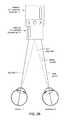
- FIGS. 1-4illustrate the basic problem of binocular misalignment.
- FIG. 1Aillustrates that when we look at a near object, like the shown cross, our vision accommodates in two ways. First, we accommodate the optical power of our eyes 1 - 1 and 1 - 2 to image the near object at a distance L onto the retina of each eyes. This is often called the accommodative response A. Second, we rotate our eyes 1 - 1 and 1 - 2 inward by an angle ⁇ , so that the visual axes 2 - 1 and 2 - 2 of the eyes are pointing at the same near object. This response is often called the accommodative convergence AC.
- the ratio of the accommodative convergence AC to the accommodative response A, AC/Ais a geometrically well-defined function, depending on the object distance L and the pupil distance PD of the two eyes.
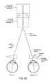
- FIGS. 1B-Cillustrate that eyes often display various forms of accommodative misalignments.
- the two eyeseach turn inward, but to a lesser degree that geometry would require. This leads to the accommodative convergence angle ⁇ being less than geometrically necessary by a misalignment angle ⁇ .
- the visual axes of the eyes 2 - 1 and 2 - 2should point into the direction denoted as the necessary accommodative alignment to properly see the near object, but, instead, they turn inward to a lesser degree and instead point to the direction denoted as relaxed or natural accommodative alignment.
- FIG. 1Cillustrates a case, when this lesser turn is asymmetrical.
- the visual axis 2 - 1 of the first eye 1 - 1properly points to the direction of the necessary accommodative alignment, while the visual axis 2 - 2 of the second eye 1 - 2 is turned inward only to the direction of the relaxed or natural accommodative alignment, that is misaligned by the accommodative misalignment angle ⁇ .
- FIGS. 2A-Dillustrate some types of accommodative misalignments.
- the definitions of misalignments used by different schools of optometry and by monographiesshow some discrepancies, and the techniques to characterize these misalignments are also varied. Therefore, the here-shown definitions are meant to be illustrative only, and analogues and equivalents are also within the scope of the illustrated terms.
- the projections into the two eyesstart to differ.
- the discrepancy between the visual perceptions of the two eyesexceeds a threshold, and the brain stops fusing the two images into a single perception.
- Objects with such difference in distance, angle, or shapeare called non-fusible objects, presenting non-fusible images.
- FIGS. 2A-Dillustrate the concept of fixation disparity, as measured by a test device, often called the Mallet box.
- the Mallet boxdisplays two vertically aligned bars, and an “X O X” horizontal “anchor”.
- the two barscan be shifted sideways.
- adjustable mirrors or prismsare placed in front of the patient's eye to achieve the same horizontal shift.
- the anchor and only one of the barsis shown for the first eye 1 - 1 as a centered bar 5 - 1 - c
- the same anchor plus only the other baris shown for the second eye 1 - 2 as a centered bar 5 - 2 - c .
- the anchor and the centered bars 5 - 1 - c and 5 - 2 - care clearly fusible. Accordingly, the brains of patients without accommodative misalignment problems will properly fuse these images.
- FIG. 2Billustrates that patients with accommodative misalignments will not fuse the images properly. What is typically observed is that, while the images of the anchor, seen by both eyes, are properly fused into a single image, the bars are perceived as shifted. The first eye 1 - 1 perceives a shifted bar 5 - 1 - s , while the second eye 1 - 2 perceives a shifted bar 5 - 2 - s .
- the angle ⁇ between the line to the image center and one of the visual axes 2 - 1 and 2 - 2is called fixation disparity.
- FIGS. 2C-Dillustrate ways to measure the angle needed to counteract, or compensate the fixation disparity.
- the two barsare counter-shifted.
- a counter-shifted bar 5 - 1 - xis shown for the first eye 1 - 1
- a counter-shifted bar 5 - 2 - xis shown for the second eye 1 - 2 .
- the barsare counter-shifted until the patient perceives the two bars as aligned.
- the angle corresponding to these counter-shifts, ⁇ *, between the visual axes and line to the counter-shifted barsis measured and is typically referred to as an associated phoria.
- the barsare not counter-shifted.
- adjustable, or exchangeable prisms 7are inserted in front of the patient's eyes. These prisms are adjusted or exchanged until the two bars are perceived as aligned by the patient. Then the prism angles, or the refraction angles of the refracted visual axes, are reported as the associated phoria ⁇ *.
- FIG. 3illustrates how increasing a partial associated phoria partially compensates fixation disparity. Strictly speaking, the (full) associated phoria, that fully compensates fixation disparity, is given by the intersect of this curve with the partial associated phoria axis. If human vision were a purely optical process, the partial associated phoria would be simply equal to the negative of the partially compensated fixation disparity. Accordingly, the curve would be a straight line through the origin, tilted by ⁇ 45 degrees, pointing from the upper left corner to the lower right corner. However, FIG. 3 illustrates that human vision is much more complex, and perception and image processing play crucial roles in it. FIG.
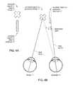
- FIGS. 4A-Cillustrate a related visual misalignment called disassociated phoria.
- disassociated phoriaTo characterize disassociated phoria, an experiment similar to that in FIGS. 2A-D can be carried out, with the difference that instead of showing fusible images 5 - 1 and 5 - 2 , the optometrists show non-fusible images 6 - 1 - s and 6 - 2 - s for the first eye 1 - 1 and the second eye 1 - 2 .
- these non-fusible imagesare the cross and the bar.
- FIG. 4Billustrates, once the eyes are unable to fuse the images, often one or both of the visual axes rotate outward.
- the visual axis 2 - 2 of the second eye 1 - 2rotates outward by an accommodative misalignment angle ⁇ .
- This angle ⁇ of the outward rotationis measured and called disassociated phoria.
- the disassociated phoriais distributed over the two eyes evenly, thus the disassociated phoria per eye equaling ⁇ /2.
- the disassociated phoria ⁇may manifest itself unevenly and has to be distributed between the eyes accordingly.
- FIG. 4Cshows a particularly clear case, when simply no image is shown for the second eye 1 - 2 , the view of the second eye 1 - 2 is blocked. This is an extreme case of non-fusible images.
- FIG. 4Bin response to the block, the visual axis 2 - 2 of the second eye 1 - 2 rotates outward by a measurable disassociated phoria angle ⁇ .
- the AC/Ais a ratio of the accommodative convergence angle reduced by the fixation disparity, ⁇ /2, (expressed with its tangent, in terms of “prism diopters” ⁇ ), divided by the accommodative distance L, expressed in diopters D.
- an AC/A ratio of 6-6.5 ⁇ /Dis necessary, while, remarkably, in large population segments the average of the misalignment-impacted AC/A ratio was measured to be about 3.5 ⁇ /D.
- various forms of accommodative misalignmentaffect a large percentage of the population, and any progress towards relief from this is highly valuable.
- a startling fact of the corresponding field of optometryis that the associated phoria angles and the disassociated phoria angles, determined by experienced practitioners, show remarkably wide variations.
- the large variability of these methodsprecludes the effective determination and compensation of accommodative misalignments.
- some embodiments of the inventioninclude a method to determine a binocular alignment, the method comprising: measuring a disassociated phoria of a first eye and a second eye of a patient at an apparent distance; and determining an accommodative convergence of the first eye and the second eye at the apparent distance using the measured disassociated phoria.
- a system to determine a binocular alignmentcomprises a stereo display, for a projection of images for a first eye and a second eye; an accommodation optics, to modify the projection of the Sages according to an apparent distance; an eye tracker, to track an orientation of the first eye and the second eye; and a computer, coupled to the stereo display, the accommodation optics and the eye tracker, to manage a determination of the binocular alignment.
- FIGS. 1A-Cillustrates various accommodative misalignments.
- FIGS. 2A-Dillustrate method to determine types of accommodative misalignments.
- FIG. 3illustrates four types of relationships between fixation disparity and partial associate phoria.
- FIGS. 4A-Cillustrate methods to determine disassociated phoria.
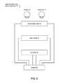
- FIG. 5illustrates a system for determining a binocular misalignment.
- FIGS. 6A-13illustrate an embodiment of the system for determining a binocular misalignment.
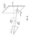
- FIG. 7illustrates an IR image by the eye tracker.
- FIGS. 8A-Billustrate an embodiment of the system for determining a binocular misalignment.
- FIG. 9illustrates an embodiment of the system for determining a binocular misalignment.
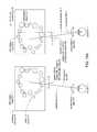
- FIGS. 10A-Billustrate embodiments of the accommodation optics.
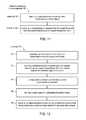
- FIG. 11illustrates a method for determining a binocular misalignment.
- FIG. 12illustrates exemplary details of the measuring step.
- FIGS. 13A-Dillustrate steps of carrying out the measuring step.
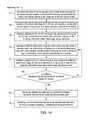
- FIG. 14illustrates exemplary details of the determining step.
- FIGS. 15A-Cillustrate steps of carrying out the determining step.
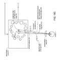
- FIG. 16illustrates a below-the-equator embodiment of the method for determining a binocular misalignment.
- the systems described in the present patent documentaddress the above articulated medical needs at least in the following aspects.
- the described system and methoddetermine the prismatic corrections only by objective measurements, without subjective input from the patient. This aspect alone greatly reduces the patient-to-patient and practitioner-to-practitioner variations of the results. In fact, studies on large samples of patients using Applicant's system and method determined prismatic corrections with a standard deviation reduced from the above mentioned 3 ⁇ to well below 1 ⁇ . This significant reduction of the results' standard deviation alone established the here-described method to the status of quantitatively predictive diagnostic methods.
- the system and methoduse both central and peripheral test images, because of a newly developed understanding of how the peripheral and the central prismatic corrections are connected.
- the described system and methodis a promising platform to determine an optimal compromise prismatic prescription that strikes the best compromise for compensating both central and peripheral accommodative misalignments.
- the described methodhas two stages, thus it determines the eventual prismatic correction in a second stage by building on the important misalignment information acquired in the first stage. As such, the method integrates knowledge determined by different methods and benefits from the information determined by all of them.
- One of the stages of the methodinvolves moving test images. Therefore, the eventually determined prismatic corrections capture and integrate the dynamic prismatic response of the eye as well.
- the reliable repeatability and small variability of the above mentioned large scale studyprovided a compelling argument that Applicants' method combined the outputs of different methods in an objective and effective manner to produce a single optimized and objective prismatic correction.
- the here-described five aspectsprovide advantages individually and in combinations.
- FIGS. 5-10illustrate a system 10 for determining a binocular alignment
- FIGS. 11-16illustrate a corresponding method 100 for determining the binocular alignment.
- FIG. 5illustrates that in some embodiments, the system 10 for determining a binocular alignment can comprise a stereo display 20 , to project visible images for a first eye 1 - 1 and a second eye 1 - 2 ; an accommodation optics 30 , to modify the projected visible images according to an apparent distance; an eye tracker 40 , to track an orientation of the first eye 1 - 1 and the second eye 1 - 2 ; and a computer 50 , coupled to the stereo display 20 , the accommodation optics 30 and the eye tracker 40 , to manage a determination of the binocular alignment.
- the eyeswill be labeled as first eye 1 - 1 and second eye 1 - 2 . This labeling can correspond to a left eye and a right eye, or vice versa.
- FIG. 6Ashows a detailed illustration of some embodiments of the system 10 .
- the eye tracker 40can include infrared light emitting diodes, or IR LEDs, 42 - 1 and 42 - 2 , positioned close to a front of the system 10 , to project infrared eye-tracking beams on the first eye 1 - 1 and the second eye 1 - 2 , as well as infrared light sources 44 - 1 and 44 - 2 , to illuminate the first eye 1 - 1 and the second eye 1 - 2 with an infrared imaging light.
- the infrared eye-tracking beams and the infrared imaging lightget both reflected from the eyes 1 - 1 and 1 - 2 .
- the eye tracker 40can further include infrared (IR) telescopes 46 - 1 and 46 - 2 , with infrared (IR) cameras 48 - 1 and 48 - 2 , to detect the infrared eye-tracking beams and the infrared imaging light, reflected from the first eye 1 - 1 and the second eye 1 - 2 .
- IRinfrared
- IRinfrared
- pairse.g., the infrared telescopes 46 - 1 and 46 - 2 .
- the infrared telescope 46abbreviating “the infrared telescopes 46 - 1 and 46 - 2 .”
- FIG. 7illustrates a resulting IR image 49 , as detected, or sensed, by the IR camera 48 .
- the “ ⁇ 1” or “ ⁇ 2” indicating a particular eyeis omitted in the description of FIG. 7 .
- the “ ⁇ 1” . . . “ ⁇ 4” notation hererefers to the four IR LEDs, all projecting IR eye tracking beams onto the same eye.
- the 42 - 4project four IR eye-tracking beams onto the eye, which reflect from the cornea, creating four so called Purkinje spots P 1 - 1 , . . . P 1 - 4 in the IR image 49 .
- the “P 1 ” notationrefers to the reflection from the proximal surface of the cornea.
- the higher indexed Purkinje spots P 2 , . . .refer to reflections from deeper lying surfaces inside the eye, such as reflections from the proximal and distal surfaces of the capsule.
- the here-described embodimentsutilize the P 1 Purkinje spots, while other embodiments may employ higher indexed Purkinje spots.
- the reflected IR imaging light of the IR light source 44is detected by the IR camera 48 as well.
- the four Purkinje spots P 1 - 1 , . . . P 1 - 4 overlaid on the detected reflected IR imaging lighttogether form the IR image 49 , as shown.
- the eye tracker 40can include an image recognition system 52 , to determine an orientation of the first eye 1 - 1 and the second eye 1 - 2 , using the detected infrared eye tracking beams, forming the Purkinje spots P 1 - 1 , . . . P 1 - 4 , and the detected infrared imaging light, together forming the IR image 49 .
- the image recognition system 52can extract, for example, an image of the contour of a pupil 3 , using edge-recognition methods. Then it can determine an orientation of the eye 1 from the center of the pupil 3 . Separately, it can determine the orientation of the eye from the Purkinje spots P 1 - 1 , . . . P 1 - 4 .
- the image recognition system 52can be a separate processor, a separate application specific integrated circuit, or it can be implemented as a software deployed in the system-managing computer 50 .
- FIGS. 6A-Billustrate that the system 10 can further include infrared-transmissive visible mirrors 24 - 1 and 24 - 2 , one for each eye, to redirect the projected visible images 26 - 1 and 26 - 2 , from the stereo display 20 to the first eye 1 - 1 and the second eye 1 - 2 ; and to transmit the reflected infrared eye tracking beam and the infrared imaging light, together 45 - 1 and 45 - 2 , from the first eye 1 - 1 and the second eye 1 - 2 .
- infrared-transmissive visible mirrors 24 - 1 and 24 - 2one for each eye, to redirect the projected visible images 26 - 1 and 26 - 2 , from the stereo display 20 to the first eye 1 - 1 and the second eye 1 - 2 ; and to transmit the reflected infrared eye tracking beam and the infrared imaging light, together 45 - 1 and 45 - 2 , from the first eye 1 - 1 and the second eye 1 - 2 .
- stereo display screens 22 - 1 and 22 - 2 of the stereo display 20can be positioned peripheral to a main optical pathway of the system 10
- the infrared telescopes 46 - 1 and 46 - 2 of the eye tracker 40can be positioned in the main optical pathway of the system 10
- the accommodation optics lenses 34 —mirror 24 —IR telescope 46 axis for each eyeis typically referred to as the main optical pathway in this embodiment.
- some labelshave been simplified.
- FIG. 6Bshows that in this embodiment, the peripheral stereo display screens 22 - 1 and 22 - 2 can project visible images 26 - 1 and 26 - 2 towards the main optical pathway of the system 10 , that are redirected by the infrared-transmissive visible mirrors 24 - 1 and 24 - 2 toward the eyes 1 - 1 and 1 - 2 .
- the reflected IR eye tracking beams and the reflected IR imaging lights, together 45 - 1 and 45 - 2reflected from the eyes 1 - 1 and 1 - 2 , are transmitted by the same infrared-transmissive visible mirrors 24 - 1 and 24 - 2 toward the IR telescopes 46 - 1 and 46 - 2 along the main optical pathway of the system 10 .
- FIG. 8Aillustrates another embodiment, where the location of the stereo display screens 22 and the IR telescopes 46 is exchanged.
- FIG. 8Billustrates that this embodiment can include visible-transmissive infrared (IR) mirrors 24 ′- 1 and 24 ′- 2 , to redirect the reflected infrared eye tracking beam and the reflected infrared imaging light, together 45 - 1 and 45 - 2 , reflected from the first eye 1 - 1 and the second eye 1 - 2 , toward the IR telescopes 46 - 1 and 46 - 2 .
- IRvisible-transmissive infrared
- the visible-transmissive infrared mirrors 24 ′- 1 and 24 ′- 2can transmit the projected visible images 26 - 1 and 26 - 2 , from the stereo display screens 22 - 1 and 22 - 2 of the stereo display 20 to the first eye 1 - 1 and the second eye 1 - 2 .
- the stereo display 20can be positioned in the main optical pathway of the system 10
- the infrared telescopes 46 of the eye tracker 40can be positioned peripheral to the main optical pathway of the system 10 .
- the accommodation optics lenses 34 —mirror 24 —stereo display screen 22 axis for each eyeis typically referred to as the main optical pathway in this embodiment.
- FIG. 9illustrates a variant of the system 10 of FIGS. 8A-B , in which the stereo display 20 can include a single stereo display screen 22 , and synchronizing glasses 28 .
- the synchronizing glasses 28can be shutter glasses or polarized glasses.
- the projected visible images 26 - 1 and 26 - 2 of the left and right stereo display screen 22 - 1 and 22 - 2 of FIGS. 8A-Bare both displayed by the single stereo display screen 22 in a rapidly alternating sequence.
- the synchronizing glasses 28can be precisely coordinated with this alternating sequence, allowing the projection of the visible images 26 - 1 and 26 - 2 to the first eye 1 - 1 and the second eye 1 - 2 in a rapidly alternating manner, creating the impression of separate images being projected into these eyes.
- the synchronizing glasses 28can be analogous to the 3D glasses used in the projection of 3D movies, and can rely on liquid crystal LCD layers that can rapidly change the circular polarization of the two lenses of the synchronizing glasses 28 .
- Such systems 10can achieve smaller footprints for the system 10 that can be advantageous. For optimal operations, a sufficiently wide field of view for the stereo display screen 22 can be helpful.
- the eye tracker 40may include small implementations of the IR cameras 48 , positioned close to the front of the system 10 , slanted at a sufficiently large angle so that the IR cameras 48 do not block the projections by the stereo display screens 22 .
- the image recognition system 52 of such implementations of the eye tracker 40can include a geometric transformation unit to determine the direction of the eye visual axes from a substantially slanted IR image 49 and Purkinje spots P 1 , . . . P 4 , possibly some spots even being obscured by the slant.
- the accommodation optics 30can include phoropter wheels 32 - 1 and 32 - 2 with a series of accommodation optics lenses 34 - 1 and 34 - 2 of varying optical power. These accommodation optics lenses 34 are useful to simulate the apparent distance for the first eye 1 - 1 and the second eye 1 - 2 .
- the system 10can be employed to project visible images 26 at different apparent distances for a patient. Doing so can involve at least two technical solutions. First, inserting the accommodation optics lenses 34 with their variable optical power into the main optical pathway can create the impression of the projected visible images 26 being farther or closer. Second, projecting the visible images 26 - 1 and 26 - 2 closer or farther from each other can simulate an appropriate vergence of these images, another important factor in making these images appear as being at the apparent distance for the patient.
- the accommodation optics 30can include, in place of the phoropter wheel 32 , or in combination with the phoropter wheel 32 , curved mirrors, trial lenses, flip in/flip out lenses, adjustable liquid lenses, deformable mirrors, z-directionally movable mirrors, rotating diffractive optical elements, translating diffractive optical elements, variable focus moire lenses, or focusing lens groups.
- FIGS. 10A-Billustrate that for the second technical solution, the accommodation optics 30 can include a pair of rotatable deflectors 36 , rotatable prisms 38 , or adjustable prisms 38 (only one shown), to deflect the projection of the images 26 - 1 and 26 - 2 to the first eye 1 - 1 and the second eye 1 - 2 , to simulate a vergence of the apparent distance for the first eye and the second eye.
- the vergencecan be simulated not by the above optical elements, but by shifting the projecting of the projected visible images 26 - 1 and 26 - 2 with the stereo display screens 22 - 1 and 22 - 2 towards each other, in other words, projecting them closer to each other.
- the accommodation optics 30 and the stereo display 20can be combined into a single light field display that includes a microlens array, where the projected visible images 26 - 1 and 26 - 2 shown on the stereo display screens 22 - 1 and 22 - 2 , combined with the optical characteristics of the microlens array can be used to vary the apparent distance of the projected visible images 26 - 1 and 26 - 2 as seen by a patient.
- the accommodation optics 30 and the stereo display 20can be combined into a single light field display that includes a mems scanner, a focus modulator, or a light source.
- FIGS. 11-16illustrate a method 100 of how to use the above described embodiments of the system 10 to determine a binocular alignment of the eyes 1 - 1 and 1 - 2 .
- FIG. 11illustrates that some embodiments of the method 100 can include a measuring 120 of a disassociated phoria of the first eye 1 - 1 and the second eye 1 - 2 of a patient at an apparent distance, and a determining 140 of an accommodative convergence of the first eye 1 - 1 and the second eye 1 - 2 at the apparent distance using the measured disassociated phoria.
- the method 100is a two-stage method, and thus its results integrate the information and knowledge revealed by the two different stages.
- the measuring 120can include projecting non-fusible visible images 26 - 1 and 26 - 2 for the first eye 1 - 1 and the second eye 1 - 2 using the stereo display 20 of the system 10 .
- the visible images 26 - 1 and 26 - 1 of FIGS. 5-10will be simply referred to as images 26 - 1 and 26 - 2 in what follows.
- Examples of projecting non-fusible images in order to determine a disassociated phoriahave been described, e.g., in relation to FIGS. 2C-D .
- the two non-fusible images 6 - 1 - s and 6 - 2 - swere of comparable appearance, or dominance.
- Some embodiments of the method 100also involve projecting such non-fusible images of comparable dominance.
- the projectingcan include projecting a dominant image for the first eye 1 - 1 , and projecting a non-dominant image for the second eye 1 - 2 .
- the eye 1 - 2 that sees the non-dominant imageoften starts wandering off after the brain's efforts to fuse the two non-fusible images fail.
- the measuring 120can include tracking the eyes 1 - 1 and 1 - 2 with the eye tracker 40 , and determining when the wandering eye 1 - 2 eventually achieves a relaxed orientation.
- Achieving this relaxed statecan be inferred, for example, by the eye tracker 40 determining that the movement of the eye 1 - 2 slowed below a threshold, or changed from a directional movement to a random jitter, or came to a halt.
- the disassociated phoriacan be measured by measuring an orientation of at least one of the first eye 1 - 1 and the second eye 1 - 2 by the eye tracker 40 .
- FIG. 12describes implementations of these steps in more detail, and FIGS. 13A-D illustrate these steps in a particular embodiment.
- the measuring 120can include the followings.
- FIG. 13Aleft panel illustrates that the projecting of a centered image step 122 can include projecting a centered image 201 - 1 , a cross in this case, on the stereo display screen 22 - 1 of the stereo display 20 of the system 10 .
- the projecting 122can be done with an apparent distance vergence 206 .
- a reference axis 202 - 1is introduced for reference as a central normal that connects a center of the first eye 1 - 1 with a center of the stereo display screen 22 - 1 .
- the centered image 201 - 1is centered in the sense that it is moved off the center of the stereo display screen 22 -I only by the apparent distance vergence angle ⁇ (L) to simulate the apparent distance vergence 206 .
- this anglewill be only referred to as the vergence angle ⁇ .
- the definition of the first eye visual axis 204 - 1can incorporate a lens or any other relevant portion of the accommodation optics 30 - 1 , through which the first eye 1 - 1 is observing the centered image 201 - 1 .
- FIG. 13Aright panel illustrates the projecting of a distributed image step 124 for the second eye 1 - 2 , in this case, a set of irregularly placed balls or spheres of random size and position, without an apparent center.
- the centered image 201 - 1is an example of a dominant image
- the distributed image 201 - 2is an example of a non-dominant image.
- the centered, dominant image 201 - 1 and the distributed, non-dominant image 201 - 2are examples of non-fusible images.
- the stereo display screen 22 - 2can be simply darkened as another embodiment of the non-fusible distributed image 201 - 2 , instead of the irregularly placed balls, in analogy to the block in FIG. 4C .
- FIG. 13Billustrates that, as described earlier, the second eye 1 - 2 will initially also turn inward by approximately the same apparent distance vergence angle ⁇ as the first eye 1 - 1 , but, after the brain fails to fuse the non-fusible central image 201 - 1 and distributed image 201 - 2 , the second eye 1 - 2 wanders away.
- the eye tracker 40can execute the tracking step 126 of the second eye 1 - 2 until the optometrist, or an automated program, determines that the wandering second eye 1 - 2 reached a relaxed state from a stabilization of the tracked rotation in the identifying step 128 .
- This stabilizationcan be defined in various ways: from the eye coming to a stop, or an amplitude of the eye's jitter becoming less than a threshold, or a directional rotation of the eye evolving into a directionless wandering.
- the eye tracker 40can measure the orientation of the relaxed second eye 1 - 2 by determining the angle ⁇ the second eye visual axis 204 - 2 with the apparent vergence 206 .
- ⁇the angular deviation of the relaxed second eye 1 - 2 from the apparent distance vergence 206 will be referred to as the disassociated phoria 208 , with its disassociated phoria angle ⁇ .
- This definitionis in close analogy with that of FIGS. 4B-C . As mentioned before, small differences exist among various practitioner's definitions of the disassociated phoria.
- the tracking step 126may involve tracking a rotation of the first eye 1 - 1 , the second eye 1 - 2 , or both.
- the disassociated phoria 208can be defined from measuring 130 a first eye phoria angle ⁇ - 1 , a second eye phoria angle ⁇ - 2 , and determining the disassociated phoria ⁇ as some type of a mean of ⁇ - 1 and ⁇ - 2 .
- FIGS. 13A-Billustrated that the steps 122 - 130 of the overall measuring step 120 can be performed as a near vision distance, e.g. L being in the range of 40 cm-100 cm.
- Lcan be in the 1 m-10 m range.
- the method 100can be performed at near vision distances corresponding to 1-3D, at distance vision distances corresponding to 0-0.5D.
- the result of the measuring step 120is the disassociated phoria 208 , with its disassociated phoria angled ⁇ .
- the second stage of the method 100carries out additional tests of the prismatic misalignment that build on the just determined disassociated phoria 208 . Therefore, the overall method 100 is a combination of the first and second stages and thus the method 100 integrates two distinct tests of prismatic misalignments, and thus integrates knowledge and data about two different types of the binocular alignment. Doing so promises a qualitatively more complete treatment and a qualitatively better improvement of the visual acuity.
- FIG. 14illustrates that the determining step 140 can include a presenting step 142 of a first image for the first eye and a second image for the second eye, with the apparent distance vergence, corrected with the measured disassociated phoria, using the stereo display; wherein the first image and the second image are fusible.
- FIG. 15Aillustrates that in some implementations of the presenting step 142 , a fusible first image 210 - 1 can be presented on the stereo display screen 22 - 1 for the first eye 1 - 1 , and a fusible second image 210 - 2 can be presented on the stereo display screen 22 - 2 for the second eye 1 - 2 .
- These fusible images 210 - 1 and 210 - 2can be peripheral.
- the peripheral images 210 - 1 and 210 - 2can be two, essentially identical circular bands, or rings, of balls or planets, as shown.
- Centers of the fusible images 210 - 1 and 210 - 2can be shifted towards each other according to the apparent distance vergence 206 , the vergence angle ⁇ being corrected by the disassociated phoria ⁇ ( 208 ), as measured in the measuring step 120 .
- the measured disassociated phoria ⁇can be symmetrically distributed as ⁇ /2- ⁇ /2 between the two eyes, as shown.
- the centers of the fusible images 210 - 1 and 210 - 2can be shifted towards each other according to ⁇ - ⁇ /2, the vergence angle ⁇ , corrected by the disassociated phoria ⁇ , relative to the reference axes 202 - 1 and 202 - 2 .
- first eye visual axis 204 - 1 and the second eye visual axis 204 - 2typically align with the apparent distance vergence 206 , corrected by the disassociated phoria 208 , as shown by these visual axes 204 pointing towards the centers of the fusible images 210 .
- the optometristmay have reasons to attribute the measured disassociated phoria ⁇ unevenly between the two eyes. It is also noted that the earlier convention is continued to make the description more comprehensible: the description will refer to a pair of “limitation N ⁇ 1 and limitation N ⁇ 2” simply as “limitations N”, where doing so does not lead to confusion.
- the shift of the fusible images 210can be impacted by the accommodation optics 30 .
- the settings of the accommodation optics 30can depend on L, the accommodative distance, or a spectacle power preferred by the patient, possibly further corrected by a cylinder or aberration.
- the fusible first image 210 - 1 and the fusible second image 210 - 2can be dynamic.
- the directed dashed arcsindicate that the rings of planets can be rotating around their center.
- making the peripheral fusible images 210 rotatecaptures peripheral prismatic effects more reliably and reproducibly.
- the radius, spatial distribution, coloring, dynamics, and speed of rotation of these fusible images 210could all be adjusted to provide the alignment information with the optimal weight.
- the first image 210 - 1 and the second image 210 - 2can be static. In some embodiments, the first image 210 - 1 and the second image 210 - 2 can be central. These embodiments may present their own medical advantages.
- FIG. 14describes and FIG. 15B illustrates that the presenting step 142 can be followed by a projecting step 144 .
- the projecting step 144can include a projecting of a first added central image 212 - 1 for the first eye 1 - 1 , and a projecting a second added central image 212 - 2 for the second eye 1 - 2 .
- These central images 212can be projected at the center of the fusible images 210 .
- the added central images 212can be projected at the center of their circulation, e.g., as a cross, as shown.
- the projecting 144 of these two added central images 212 - 1 and 212 - 2can be performed in an alternating manner, using the stereo display 20 .
- the cross 212 - 1is shown with a solid line
- the other added central image, 212 - 2is shown with a dashed line in FIG. 15 B.
- the period of the alternatingcan be selected according to several different criteria, and can be less than 1 second, in a range of 1-100 second, in some cases in a range of 5-10 seconds.
- the angle of the disassociated phoria 208measured in step 120 , completely captured the binocular alignments of the eyes 1 , then the eyes 1 would not have needed to adjust to the projecting step 144 of the added central images 212 with the vergence angle ⁇ , corrected by the disassociated phoria angle ⁇ /2. This would have manifested itself in that the eye visual axes 204 would have had remained aligned with the vergence angle ⁇ , corrected by the disassociated phoria angle ⁇ /2 after the projecting step 144 .
- Tracking 146an adjustment of the first eye in response to the projecting of the first added central image, and tracking an adjustment of the second eye in response to the projecting of the second added central image, using an eye tracker;
- FIG. 14describes and FIG. 15B illustrates that in order to determine residual prismatic misalignments, the projecting step 144 can be followed by the tracking 146 of an adjustment of the first eye 1 - 1 in response to the projecting of the first added central image 212 - 1 , and tracking an adjustment of the second eye 1 - 2 in response to the projecting of the second added central image 212 - 2 , using an eye tracker 40 .
- FIG. 14describes and FIG. 15B illustrates that in order to determine residual prismatic misalignments, the projecting step 144 can be followed by the tracking 146 of an adjustment of the first eye 1 - 1 in response to the projecting of the first added central image 212 - 1 , and tracking an adjustment of the second eye 1 - 2 in response to the projecting of the second added central image 212 - 2 , using an eye tracker 40 .
- 15Billustrates that the first eye 1 - 1 adjusts to the projecting 144 by rotating the first eye visual axis 204 - 1 with an adjustment angle of the first eye 214 - 1 , denoted by ⁇ - 1
- the second eye 1 - 2adjusts by rotating the second eye visual axis 204 - 2 with an adjustment angle of the second eye 214 - 2 , denoted by ⁇ - 2
- the angleswill be referenced to the apparent distance vergence corrected by the disassociated phoria, having the angle ⁇ - ⁇ /2, instead of the reference axis 202 .
- FIG. 15Cshows that the determining the accommodative convergence step 140 next includes projecting 148 a shifted first added central image 212 - 1 with a first iterative associated phoria ⁇ (n)- 1 , to reduce the adjustment of the first eye 1 - 1 , and projecting a shifted second added central image 212 - 2 with a second iterative associated phoria ⁇ (n)- 2 , to reduce the adjustment of the second eye 1 - 2 .
- the adjustment of the eyecan be measured by a change of the adjustment angle ⁇ (n)- 1 , as elaborated below.
- FIG. 15Cshows the first shifted image axis 216 - 1 , connecting the shifted first added central image 212 - 1 to the first eye 1 - 1 .
- the step indexis shown in the above definitions as ⁇ (n)- 1 and ⁇ (n)- 1 : the first first iterative associated phoria is denoted with ⁇ ( 1 )- 1 , the first second iterative associated phoria by ⁇ ( 1 )- 2 , and so on.
- the “ ⁇ 1” and “ ⁇ 2” indicescontinue to label the angles of the first eye 1 - 1 and the second eye 1 - 2 , respectively, while the “(1)”, “(2)”, . . . “(n)” indices label the first, second, and n-th steps of the iterative process.
- the projecting 148 of these shifted added central images 212 - 1 and 212 - 2can be performed in an alternating manner, using the stereo display 20 and the computer 50 .
- FIG. 15Cfurther illustrates that the projecting step 148 can be followed by the tracking 150 of an adjustment of the first eye 1 - 1 in response to the projecting of the shifted first added central image 212 - 1 , and tracking an adjustment of the second eye 1 - 2 in response to the projecting of the shifted second added central image 212 - 2 , using the eye tracker 40 .
- the tracking step 150includes the tracking of the adjustment angle ⁇ (n+1)- 1 of the first eye 1 - 1 in response to the projecting 148 of the shifted first added central image 212 - 1 with the first iterative associated phoria ⁇ (n)- 1 .
- This tracking step 150is analogous to the tracking step 146 . It is distinguished by the iterative step index having grown from (n) to (n+1).
- embodiments of the methodinvolve shifting the added central image 212 with the iterative associated phoria ⁇ (n), tracking the responsive adjustment angle ⁇ (n+1) of the eye 1 , determining the adjustment of the eye 1 from the change of the adjustment angle ⁇ (n+1)- ⁇ (n), and then repeating the shifting of the added central image 212 with a new iterative associated phoria ⁇ (n+1), selected in magnitude and sign to reduce the change of the adjustment angle ⁇ (n+1)- ⁇ (n).
- the magnitude of ⁇ (n+1)- ⁇ (n)can be chosen to be equal to ⁇ (n+1)- ⁇ (n):
- ⁇
- Other, non-linear, polynomial, non-analytic or analytic relationshipscan also be employed in various embodiments.
- the methodcan return to the projecting step 148 of the shifted first added central image 212 , as shown in FIG. 15C .
- step (n)the adjustment of the eye, as characterized by, e.g., the change of the adjustment angle
- the disassociated phoria ⁇ and the stabilized associated phoria ⁇were typically defined for the two eyes together.
- the per-eye valuesare half of the here-defined angles, in symmetrical cases.
- the identifying step 154can be followed by the identifying 156 of a sum of the disassociated phoria ⁇ and the stabilized associated phoria ⁇ , ( ⁇ + ⁇ ), as a correction to the accommodative convergence AC, with the accommodative convergence angle ⁇ , that corresponds to the apparent distance.
- the full, or fully corrected, accommodative convergencedetermined by the method 100 , can be expressed via the tangent of the corresponding full, or fully corrected, accommodative convergence angle: [ ⁇ ( ⁇ + ⁇ )/2], in terms of prism diopters ⁇ .
- Another difference compared to previous methodsis the particular system 10 and method 100 , by which ⁇ was determined.
- the binocular alignmentcan be again characterized by the AC/A ratio, the ratio of the accommodative convergence AC to the accommodative response A, to characterize the binocular alignment.
- This AC/A ratiocan be determined for a single distance, or can be formed from AC and A values for multiple distances.
- the fully corrected accommodative convergence ACwill be simply referred to as accommodative convergence AC.
- the method 100can include determining a distance vision accommodative convergence AC(L d ) as an accommodative convergence resulting from performing the method 100 at a distance vision apparent distance L d ; and determining a near vision accommodative convergence AC(L n ) as an accommodative convergence resulting from performing the method at a near vision apparent distance L n .
- the measuring 120 at the apparent distance and the determining 140 at the apparent distancecan be performed using the accommodation optics 30 .
- embodiments of the method 100can be performed without soliciting a substantive response from the patient to determine one of the key quantities or angles. (Of course, non-substantive responses about, e.g., comfort, can very well be part of the method 100 .) This is one of the keys why the method 100 delivers measurements with high reproducibility.
- FIG. 16illustrates that in some embodiments, when the method 100 is performed at apparent distances corresponding to near vision, the disassociated phoria and the accommodative convergence corresponding to the near vision can be determined at viewing angles below an equatorial direction 9 by displaying the centered images 201 below the equatorial direction 9 .
Landscapes
- Health & Medical Sciences (AREA)
- Life Sciences & Earth Sciences (AREA)
- Engineering & Computer Science (AREA)
- Surgery (AREA)
- General Health & Medical Sciences (AREA)
- Biophysics (AREA)
- Biomedical Technology (AREA)
- Heart & Thoracic Surgery (AREA)
- Medical Informatics (AREA)
- Molecular Biology (AREA)
- Physics & Mathematics (AREA)
- Animal Behavior & Ethology (AREA)
- Ophthalmology & Optometry (AREA)
- Public Health (AREA)
- Veterinary Medicine (AREA)
- Multimedia (AREA)
- Signal Processing (AREA)
- Human Computer Interaction (AREA)
- Eye Examination Apparatus (AREA)
- Eyeglasses (AREA)
Abstract
Description
- Projecting122 a centered image for the first eye with an apparent distance vergence, using a stereo display;
- projecting124 a distributed image for the second eye with an apparent distance vergence, using the stereo display, wherein the centered image and the distributed image are non-fusible;
- tracking126 a rotation of at least one of the first eye and the second eye using an eye tracker;
- identifying128 a relaxed state from a stabilization of the tracked rotation; and
- measuring130 the disassociated phoria by measuring an orientation of at least one of the first eye and the second eye in the relaxed state using the eye tracker and a computer.
- projecting148 a shifted first added central image with a first iterative associated phoria, to reduce the adjustment of the first eye, and projecting a shifted second added central image with a second iterative associated phoria, to reduce the adjustment of the second eye, in an alternating manner, using the stereo display and a computer;
- tracking150 an adjustment of the first eye in response to the projecting of the shifted first added central image, and tracking an adjustment of the second eye in response to the projecting of the shifted second added central image using the eye tracker;
- determining152 whether an effective adjustment of the first and second eye is less than an adjustment threshold, and returning to the projecting the shifted first added central image step if the effective adjustment of the first and second eye is greater than the adjustment threshold;
- identifying154 a stabilized associated phoria from the last first iterative associated phoria and the last second iterative associated phoria, if the effective adjustment of the first and second eye is less than the adjustment threshold; and
- identifying156 a sum of the disassociated phoria and the stabilized associated phoria as a correction to the accommodative convergence, corresponding to the apparent distance. These steps are described in some detail next.
binocular alignment=[AC(Ld)−AC(Ln)]/[A(Ld)−A(Ln)] (1)
- (1) The method100 does not use the patient's subjective responses as key inputs.
- (2) The method100 uses both peripheral images, e.g. the
images 124 and210, and central images, e.g. the images201 and212. - (3) The method100 uses a two-stage method with the measuring
step 120 and the determiningstep 140, gathering and utilizing information about both central vision and peripheral vision. - (4) The method100 uses moving test images, e.g. the images210.
- (5) The method100 developed a particular definition of the accommodative convergence and the protocol for its determination, e.g. in steps142-156, and proved with extensive testing that eye glasses prescribed using this definition reduce eye-strain related discomfort particularly efficiently.
Claims (11)
Priority Applications (17)
| Application Number | Priority Date | Filing Date | Title |
|---|---|---|---|
| US15/696,161US10420467B2 (en) | 2017-09-05 | 2017-09-05 | Method and system for measuring binocular alignment |
| CN201880066820.7ACN111263609B (en) | 2017-09-05 | 2018-09-04 | Methods and systems for measuring binocular alignment |
| PCT/US2018/049428WO2019050877A1 (en) | 2017-09-05 | 2018-09-04 | Method and system for measuring binocular alignment |
| EP18853728.6AEP3678530A4 (en) | 2017-09-05 | 2018-09-04 | BINOCULAR ALIGNMENT MEASUREMENT METHOD AND SYSTEM |
| EP20190684.9AEP3756535B1 (en) | 2017-09-05 | 2018-09-04 | Method and system for measuring binocular alignment |
| CA3074858ACA3074858A1 (en) | 2017-09-05 | 2018-09-04 | Method and system for measuring binocular alignment |
| CN202410184813.4ACN117982095A (en) | 2017-09-05 | 2018-09-04 | Method and system for measuring binocular alignment |
| MX2020002524AMX2020002524A (en) | 2017-09-05 | 2018-09-04 | Method and system for measuring binocular alignment. |
| AU2018330035AAU2018330035B2 (en) | 2017-09-05 | 2018-09-04 | Method and system for measuring binocular alignment |
| JP2020513643AJP7602911B2 (en) | 2017-09-05 | 2018-09-04 | Method and system for measuring binocular eye position |
| ES20190684TES2992322T3 (en) | 2017-09-05 | 2018-09-04 | Method and system for measuring binocular alignment |
| US16/579,826US11589745B2 (en) | 2017-09-05 | 2019-09-23 | Method and system for measuring binocular alignment |
| US17/179,402US12114930B2 (en) | 2017-09-05 | 2021-02-19 | System for measuring binocular alignment with adjustable displays and eye trackers |
| US18/065,182US11903645B2 (en) | 2017-09-05 | 2022-12-13 | Method and system for measuring binocular alignment |
| US18/462,900US20230414100A1 (en) | 2017-09-05 | 2023-09-07 | Headset-based system for measuring binocular alignment |
| US18/414,579US20240148246A1 (en) | 2017-09-05 | 2024-01-17 | Method and system for measuring binocular alignment |
| US18/808,692US20240407648A1 (en) | 2017-09-05 | 2024-08-19 | System for measuring binocular alignment with adjustable displays and eye trackers |
Applications Claiming Priority (1)
| Application Number | Priority Date | Filing Date | Title |
|---|---|---|---|
| US15/696,161US10420467B2 (en) | 2017-09-05 | 2017-09-05 | Method and system for measuring binocular alignment |
Related Child Applications (1)
| Application Number | Title | Priority Date | Filing Date |
|---|---|---|---|
| US16/579,826ContinuationUS11589745B2 (en) | 2017-09-05 | 2019-09-23 | Method and system for measuring binocular alignment |
Publications (2)
| Publication Number | Publication Date |
|---|---|
| US20190069777A1 US20190069777A1 (en) | 2019-03-07 |
| US10420467B2true US10420467B2 (en) | 2019-09-24 |
Family
ID=65517641
Family Applications (1)
| Application Number | Title | Priority Date | Filing Date |
|---|---|---|---|
| US15/696,161ActiveUS10420467B2 (en) | 2017-09-05 | 2017-09-05 | Method and system for measuring binocular alignment |
Country Status (9)
| Country | Link |
|---|---|
| US (1) | US10420467B2 (en) |
| EP (2) | EP3678530A4 (en) |
| JP (1) | JP7602911B2 (en) |
| CN (2) | CN111263609B (en) |
| AU (1) | AU2018330035B2 (en) |
| CA (1) | CA3074858A1 (en) |
| ES (1) | ES2992322T3 (en) |
| MX (1) | MX2020002524A (en) |
| WO (1) | WO2019050877A1 (en) |
Cited By (20)
| Publication number | Priority date | Publication date | Assignee | Title |
|---|---|---|---|---|
| US10642355B1 (en) | 2018-10-22 | 2020-05-05 | Evolution Optiks Limited | Light field display, adjusted pixel rendering method therefor, and vision correction system and method using same |
| US10699373B1 (en) | 2018-10-22 | 2020-06-30 | Evolution Optiks Limited | Light field display, adjusted pixel rendering method therefor, and vision correction system and method using same |
| US10761604B2 (en) | 2018-10-22 | 2020-09-01 | Evolution Optiks Limited | Light field vision testing device, adjusted pixel rendering method therefor, and vision testing system and method using same |
| US10860099B2 (en) | 2018-10-22 | 2020-12-08 | Evolution Optiks Limited | Light field display, adjusted pixel rendering method therefor, and adjusted vision perception system and method using same addressing astigmatism or similar conditions |
| US10936064B2 (en) | 2018-10-22 | 2021-03-02 | Evolution Optiks Limited | Light field display, adjusted pixel rendering method therefor, and adjusted vision perception system and method using same addressing astigmatism or similar conditions |
| US11262901B2 (en) | 2015-08-25 | 2022-03-01 | Evolution Optiks Limited | Electronic device, method and computer-readable medium for a user having reduced visual acuity |
| US11287883B2 (en) | 2018-10-22 | 2022-03-29 | Evolution Optiks Limited | Light field device, pixel rendering method therefor, and adjusted vision perception system and method using same |
| US11327563B2 (en) | 2018-10-22 | 2022-05-10 | Evolution Optiks Limited | Light field vision-based testing device, adjusted pixel rendering method therefor, and online vision-based testing management system and method using same |
| US11353699B2 (en) | 2018-03-09 | 2022-06-07 | Evolution Optiks Limited | Vision correction system and method, light field display and light field shaping layer and alignment therefor |
| US11487361B1 (en) | 2019-11-01 | 2022-11-01 | Evolution Optiks Limited | Light field device and vision testing system using same |
| US11500460B2 (en) | 2018-10-22 | 2022-11-15 | Evolution Optiks Limited | Light field device, optical aberration compensation or simulation rendering |
| US11500461B2 (en) | 2019-11-01 | 2022-11-15 | Evolution Optiks Limited | Light field vision-based testing device, system and method |
| US11635617B2 (en) | 2019-04-23 | 2023-04-25 | Evolution Optiks Limited | Digital display device comprising a complementary light field display or display portion, and vision correction system and method using same |
| US11693239B2 (en) | 2018-03-09 | 2023-07-04 | Evolution Optiks Limited | Vision correction system and method, light field display and light field shaping layer and alignment therefor |
| US11823598B2 (en) | 2019-11-01 | 2023-11-21 | Evolution Optiks Limited | Light field device, variable perception pixel rendering method therefor, and variable perception system and method using same |
| US11902498B2 (en) | 2019-08-26 | 2024-02-13 | Evolution Optiks Limited | Binocular light field display, adjusted pixel rendering method therefor, and vision correction system and method using same |
| US11903645B2 (en) | 2017-09-05 | 2024-02-20 | Neurolens, Inc. | Method and system for measuring binocular alignment |
| US12112665B2 (en) | 2019-11-01 | 2024-10-08 | Evolution Optiks Limited | Light field device, variable perception pixel rendering method therefor, and variable perception system and method using same |
| US12159354B2 (en) | 2019-04-23 | 2024-12-03 | Evolution Optiks Limited | Light field display and vibrating light field shaping layer and vision testing and/or correction device |
| US12360592B2 (en) | 2019-11-01 | 2025-07-15 | Evolution Optiks Limited | Light field device and vision testing system using same |
Families Citing this family (10)
| Publication number | Priority date | Publication date | Assignee | Title |
|---|---|---|---|---|
| US10048512B2 (en)* | 2016-10-08 | 2018-08-14 | eyeBrain, Medical, Inc. | Low-convergence spectacles |
| US12114930B2 (en) | 2017-09-05 | 2024-10-15 | Neurolens, Inc. | System for measuring binocular alignment with adjustable displays and eye trackers |
| WO2020144670A1 (en)* | 2019-01-13 | 2020-07-16 | Visionix - Luneau Technology (Israel) | Virtual reality ocular examination system |
| US11503195B2 (en)* | 2019-02-26 | 2022-11-15 | Westboro Photonics Inc. | Method and apparatus for imaging circadiometer |
| JP7728741B2 (en)* | 2019-07-05 | 2025-08-25 | エシロール・アンテルナシオナル | Method for inducing controlled changes in accommodation in a subject's eye - Patent Application 20070122997 |
| EP4171353A2 (en)* | 2020-06-29 | 2023-05-03 | Essilor International | Phoropter and optometry device for testing an individual's eyes |
| CN112807200B (en)* | 2021-01-08 | 2022-07-19 | 上海青研科技有限公司 | Strabismus training equipment |
| EP4294251A4 (en)* | 2021-02-19 | 2025-04-16 | Neurolens, Inc. | SYSTEM FOR MEASURING BINOCULAR ALIGNMENT USING DISPLAY DEVICES AND ADJUSTABLE EYE TRACKER |
| WO2022229210A1 (en)* | 2021-04-28 | 2022-11-03 | Essilor International | Optometric testing device and process |
| CN113524194B (en)* | 2021-04-28 | 2023-03-21 | 重庆理工大学 | Target grabbing method of robot vision grabbing system based on multi-mode feature deep learning |
Citations (95)
| Publication number | Priority date | Publication date | Assignee | Title |
|---|---|---|---|---|
| US3245745A (en) | 1964-07-16 | 1966-04-12 | Textron Inc | Post-operative multifocal cataract lenses with base-in prismatic nearvision segments |
| US4056311A (en) | 1973-08-16 | 1977-11-01 | American Optical Corporation | Progressive power ophthalmic lens having a plurality of viewing zones with non-discontinuous variations therebetween |
| US4222639A (en) | 1978-10-31 | 1980-09-16 | Sheedy James E | Apparatus and system for analyzing fixation disparity |
| US4240719A (en) | 1976-03-11 | 1980-12-23 | Optisch Werke G. Rodenstock | Progressive ophthalmic lens |
| US4253747A (en) | 1978-05-12 | 1981-03-03 | Essilor International (Compagnie Generale D'optique) | Method of preparing a refractive surface of a progressively variable focal power ophthalmic lens |
| US4580882A (en) | 1983-04-21 | 1986-04-08 | Benjamin Nuchman | Continuously variable contact lens |
| US4580883A (en) | 1980-12-05 | 1986-04-08 | Kabushiki Kaisha Suwa Seikosha | Progressive multifocal ophthalmic lenses |
| US4606626A (en) | 1982-12-13 | 1986-08-19 | Seiko Epson Corporation | Progressive multifocal ophthalmic lenses with prism for correcting chromatic aberration |
| US4756305A (en) | 1986-09-23 | 1988-07-12 | Mateik William J | Eye training device |
| US4906090A (en) | 1984-09-15 | 1990-03-06 | Optische Werke G. Rodenstock | Spectacle lens for half-eye spectacles |
| US4961639A (en) | 1989-06-30 | 1990-10-09 | Lazarus Stuart M | Prism section lens spectacles |
| US5026151A (en) | 1989-06-23 | 1991-06-25 | Mentor O & O, Inc. | Visual function tester with binocular vision testing |
| US5200859A (en) | 1988-05-06 | 1993-04-06 | Ergonomic Eyecare Products, Inc. | Vision saver for computer monitor |
| US5305028A (en) | 1990-04-24 | 1994-04-19 | Hitoshi Okano | Multifocal lens provided with progressive focal segment |
| US5381191A (en) | 1993-04-14 | 1995-01-10 | Levy; Chauncey F. | Glasses for reducing eye strain during viewing of a CRT screen |
| US5557348A (en) | 1993-06-29 | 1996-09-17 | Nikon Corporation | Progressive power lens |
| JPH1022724A (en) | 1996-07-05 | 1998-01-23 | Hitachi Cable Ltd | Leaky waveguide and method of manufacturing the same |
| US5724120A (en) | 1995-10-02 | 1998-03-03 | Svochak; Jan B. | Multifocal contact lens and method and apparatus for making the same |
| US5728156A (en) | 1996-08-06 | 1998-03-17 | Prism Opthalmics, L.L.C. | Prismatic intraocular lenses and related methods of in situ alteration of their optical characteristics |
| US5782894A (en) | 1997-03-05 | 1998-07-21 | Israel; Ben | Device and method for improving ocular focusing at near vision points |
| US5946075A (en) | 1996-05-21 | 1999-08-31 | Horn; Gerald | Vision screening system |
| US5969790A (en) | 1996-12-20 | 1999-10-19 | Onufryk; Michael | Multi prism image enhancing lens system and method of making same |
| US6019470A (en) | 1995-11-24 | 2000-02-01 | Seiko Epson Corporation | Progressive multifocal lens and manufacturing method of eyeglass lens and progressive multifocal lens |
| US6062691A (en) | 1999-04-19 | 2000-05-16 | Markson; Jeffrey | System kit and method for reducing ocular discomfort and vision problems associated with sustained close-range viewing |
| US6106819A (en) | 1996-12-31 | 2000-08-22 | Sucher; David F. | Methods of treating headache and functional extraocular and intraocular myotendinitis |
| US6142624A (en) | 1998-07-17 | 2000-11-07 | Sola International Holdings Ltd. | Wide field spherical lenses and single design spectacle frames therefor |
| US6318857B1 (en) | 1998-12-09 | 2001-11-20 | Asahi Kogaku Kogyo Kabushiki Kaisha | Variable power spectacles |
| US6347869B1 (en) | 1999-05-24 | 2002-02-19 | Shuxiang Xu | Convex lens and stepped prism combined glasses |
| US6364481B1 (en) | 1997-07-18 | 2002-04-02 | Sola International Holdings Ltd. | Lens with surface correction |
| FR2814819A1 (en) | 2000-09-29 | 2002-04-05 | Xavier Carriou | Progressive lens for correcting presbyopia has distant vision centre corresponding to pupillary divergence for distant vision |
| US20020051116A1 (en) | 1998-11-06 | 2002-05-02 | Van Saarloos Paul Phillip | Eye tracker for refractive surgery |
| US20020099305A1 (en) | 2000-12-28 | 2002-07-25 | Matsushita Electic Works, Ltd. | Non-invasive brain function examination |
| JP2002253509A (en) | 2000-12-28 | 2002-09-10 | Matsushita Electric Works Ltd | Method and device for examining brain function, brain function examining system, and method, program, and device for brain function examining service |
| US6505934B1 (en) | 2001-04-27 | 2003-01-14 | Johnson & Johnson Vision Care, Inc. | Progressive addition lenses with prism power added to improve wearer comfort |
| US6547387B1 (en) | 2002-02-15 | 2003-04-15 | David A. Katsantones | Eyeglass appliance for reducing eye strain |
| US6579478B2 (en) | 1992-08-18 | 2003-06-17 | Q2100, Inc. | Progressive lens apparatus and process |
| CN1438852A (en) | 2000-06-28 | 2003-08-27 | 爱视有限责任公司 | Vision testing system |
| US6652097B2 (en) | 2001-10-12 | 2003-11-25 | Pentax Corporation | Progressive-power spectacle lens |
| FR2850763A1 (en) | 2003-02-03 | 2004-08-06 | Essilor Int | APHTHALMIC LENS WITH PROGRESSIVE ADDITION OF POWER AND PRISM |
| US6776486B2 (en) | 2002-05-31 | 2004-08-17 | Crossbows Optical Limited | Progressive addition power lens |
| US6789898B2 (en) | 2002-06-17 | 2004-09-14 | Essilor International | Model for representing an ophthalmic lens surface |
| US6871954B2 (en) | 1998-03-18 | 2005-03-29 | Victor L. Copeland | Optically superior decentered over-the counter sunglasses |
| US6956682B2 (en) | 2003-06-26 | 2005-10-18 | Johnson & Johnson Vision Care, Inc. | Method for designing progressive addition lenses |
| US20060092375A1 (en) | 2004-10-29 | 2006-05-04 | Menezes Edgar V | Multifocal lenses for pre-presbyopic individuals |
| US20060170863A1 (en) | 2005-02-03 | 2006-08-03 | Krall Jeffrey P | Multi-focal ophthalmic lens with base in prism |
| US20060244915A1 (en) | 2005-04-29 | 2006-11-02 | Michael Clemons | Vision testing apparatus |
| WO2007068819A1 (en) | 2005-12-13 | 2007-06-21 | Essilor International | Method for determining a set of progressive multifocal ophthalmic lenses |
| US20070182923A1 (en) | 2003-11-27 | 2007-08-09 | Hoya Corporation | Bi-aspherical type progressive-power lens and method of designing the same |
| US7290878B1 (en) | 2003-10-15 | 2007-11-06 | Albert John Hofeldt | Machine for binocular testing and a process of formatting rival and non-rival stimuli |
| WO2008012649A2 (en) | 2006-07-25 | 2008-01-31 | Hesp Technology Srl | Apparatus for measuring the visual acuity of a person |
| US20080049152A1 (en) | 2005-11-03 | 2008-02-28 | University Of Central Florida Research Foundation, Inc. | Head mounted display with eye accommodation |
| US20080117289A1 (en) | 2004-08-06 | 2008-05-22 | Schowengerdt Brian T | Variable Fixation Viewing Distance Scanned Light Displays |
| US20080278676A1 (en) | 2007-05-08 | 2008-11-13 | Gunnar Optiks, Llc | Eyewear for reducing symptoms of computer vision syndrome |
| US20090153796A1 (en)* | 2005-09-02 | 2009-06-18 | Arthur Rabner | Multi-functional optometric-ophthalmic system for testing diagnosing, or treating, vision or eyes of a subject, and methodologies thereof |
| US20090185137A1 (en) | 2008-01-21 | 2009-07-23 | Krall Jeffrey P | System and method for measuring fixation disparity and proprioceptive misalignment of the visual system |
| US20100066974A1 (en) | 2008-06-13 | 2010-03-18 | Gunnar Optiks, Llc | Low-power eyewear for reducing symptoms of computer vision syndrome |
| US7703921B2 (en) | 2001-07-06 | 2010-04-27 | Carl Zeiss Meditec Ag | Method and device for tracking eye movements |
| US20100109176A1 (en) | 2008-11-03 | 2010-05-06 | Chris Davison | Machined lens molds and methods for making and using same |
| US20100271590A1 (en) | 2007-12-04 | 2010-10-28 | Hoya Corporation | Pair of progressive power lens and method for designing same |
| EP2301422A1 (en) | 2009-09-29 | 2011-03-30 | Nidek Co., Ltd. | Optometric apparatus |
| US20110090455A1 (en) | 2009-10-14 | 2011-04-21 | PixelOptics | Opthalmic Lens With Regressive and Non-Regressive Rotationally Symmetric Optical Design Elements |
| WO2011067361A1 (en) | 2009-12-02 | 2011-06-09 | Retcorr Ab | An apparatus and method for establishing and/or improving binocular vision |
| US8042940B2 (en) | 2009-03-24 | 2011-10-25 | Crossbows Optical Limited | Opthalmic lenses having reduced base out prism |
| US20110317127A1 (en) | 2010-06-29 | 2011-12-29 | Seiko Epson Corporation | Progressive Power Eyeglass Lens and Design Method Thereof |
| US20120002163A1 (en)* | 2010-07-02 | 2012-01-05 | Amo Wavefront Sciences, Llc | Compact Binocular Adaptive Optics Phoropter |
| US8100529B2 (en) | 2008-07-31 | 2012-01-24 | Hoya Corporation | Progressive-addition lens |
| US20120019775A1 (en) | 2010-07-22 | 2012-01-26 | Albert Tyrin | Training method for accommodative and vergence systems, and multifocal lenses therefor |
| US20120019776A1 (en) | 2008-12-26 | 2012-01-26 | Guillaume Giraudet | Method for Providing a Spectacle Ophthalmic Lens by Calculating or Selecting a Design |
| US20120081661A1 (en) | 2009-02-05 | 2012-04-05 | Hoya Corporation | Eyeglass lens evaluation method, eyeglass lens design method, eyeglass lens manufacturing method, eyeglass lens manufacturing system, and eyeglass lens |
| JP2012100759A (en) | 2010-11-08 | 2012-05-31 | Panasonic Corp | Eye position measurement system |
| US20120200822A1 (en) | 2005-08-22 | 2012-08-09 | Seiko Epson Corporation | Progressive-power lens |
| US20120250152A1 (en) | 2011-03-31 | 2012-10-04 | Honeywell International Inc. | Variable focus stereoscopic display system and method |
| WO2012160741A1 (en) | 2011-05-20 | 2012-11-29 | パナソニック株式会社 | Visual fatigue-measuring apparatus, method thereof, visual fatigue-measuring system and three-dimensional glasses |
| US20130010097A1 (en) | 2010-03-16 | 2013-01-10 | Qinetiq Limited | Eye tracking apparatus |
| US8425034B2 (en) | 2010-02-08 | 2013-04-23 | Carl Zeiss Vision International Gmbh | Lens element with improved prismatic power |
| US20130265540A1 (en) | 2010-11-30 | 2013-10-10 | Gregor Esser | Method for calculating a spectacle lens with improved near zone |
| US20130293531A1 (en) | 2012-05-01 | 2013-11-07 | Microsoft Corporation | User perception of visual effects |
| US20130308099A1 (en) | 2012-05-18 | 2013-11-21 | Halcyon Bigamma | Eye tracking headset and system for neuropsychological testing including the detection of brain damage |
| CN103815866A (en) | 2010-04-21 | 2014-05-28 | 松下电器产业株式会社 | Visual function testing method and control device |
| US20140327875A1 (en) | 2011-03-08 | 2014-11-06 | Ronald Blum | Advanced electro-active optic device |
| US20150049301A1 (en) | 2013-08-15 | 2015-02-19 | eyeBrain Medical, Inc. | Methods and lenses for alleviating asthenopia |
| US20150212338A1 (en) | 2012-07-09 | 2015-07-30 | Hoya Corporation | Spectacle lens and method for designing the same, method for manufacturing spectacle lens, and program |
| US20150226983A1 (en) | 2014-02-10 | 2015-08-13 | Shamir Optical Industry Ltd. | Quasi progressive lenses for eyewear |
| US20150346515A1 (en) | 2012-12-19 | 2015-12-03 | Hoya Corporation | Spectacle lenses |
| WO2016007124A1 (en) | 2014-07-07 | 2016-01-14 | eyeBrain Medical, Inc. | System for measuring visual fixation disparity |
| US9237843B1 (en) | 2014-07-07 | 2016-01-19 | eyeBrain Medical, Inc. | System for measuring visual fixation disparity |
| WO2016020229A1 (en) | 2014-08-04 | 2016-02-11 | Essilor International (Compagnie Generale D'optique) | Spectacles comprising a pair of progressive lenses |
| US9274351B2 (en) | 2013-03-01 | 2016-03-01 | Essilor International (Compagnie Generale D'optique) | Method for optimizing the postural prism of an ophthalmic lens |
| US20160073870A1 (en) | 2013-11-07 | 2016-03-17 | Ohio State Innovation Foundation | Automated detection of eye alignment |
| WO2016101204A1 (en) | 2014-12-25 | 2016-06-30 | Essilor International (Compagnie Generale D'optique) | Device for measuring phoria and method for measuring phoria using the device |
| US20170148215A1 (en) | 2015-11-19 | 2017-05-25 | Oculus Vr, Llc | Eye Tracking for Mitigating Vergence and Accommodation Conflicts |
| WO2017131770A1 (en) | 2016-01-29 | 2017-08-03 | Hewlett-Packard Development Company, L.P | Viewing device adjustment based on eye accommodation in relation to a display |
| US20180136486A1 (en)* | 2016-07-25 | 2018-05-17 | Magic Leap, Inc. | Light field processor system |
| US10048511B2 (en) | 2016-10-08 | 2018-08-14 | eyeBrain, Medical, Inc. | Eye-strain reducing lens |
| US10048512B2 (en) | 2016-10-08 | 2018-08-14 | eyeBrain, Medical, Inc. | Low-convergence spectacles |
Family Cites Families (17)
| Publication number | Priority date | Publication date | Assignee | Title |
|---|---|---|---|---|
| JPS6092730A (en)* | 1983-10-26 | 1985-05-24 | 株式会社トプコン | Eye position inspection device |
| JPH11197108A (en)* | 1998-01-13 | 1999-07-27 | Nikon Corp | Visual function testing device |
| GB0003333D0 (en)* | 2000-02-15 | 2000-04-05 | Marshall Ian | Ophthalmoscope optical system |
| US20090015379A1 (en)* | 2004-05-19 | 2009-01-15 | Einar Rosenberg | Apparatus and method for context-based wireless information processing |
| RU2268637C2 (en)* | 2004-03-22 | 2006-01-27 | Андрей Викторович Ларичев | Aberration meter provided with vision acuity testing system (versions), device and method of adjustment |
| US20150205111A1 (en)* | 2014-01-21 | 2015-07-23 | Osterhout Group, Inc. | Optical configurations for head worn computing |
| RU2016102317A (en)* | 2010-05-29 | 2018-11-21 | Вэньюй ЦЗЯН | SYSTEMS, METHODS AND APPARATUS FOR CREATION AND USE OF GLASSES WITH ADAPTIVE LENS ON THE BASIS OF DETERMINING THE DISTANCE OF OBSERVATION AND TRACKING OF THE VIEW IN THE CONDITIONS OF LOW ENERGY CONSUMPTION |
| US8939579B2 (en)* | 2011-01-28 | 2015-01-27 | Light Prescriptions Innovators, Llc | Autofocusing eyewear, especially for presbyopia correction |
| NZ627582A (en)* | 2012-01-24 | 2016-11-25 | Univ Arizona State | Compact eye-tracked head-mounted display |
| US8814361B2 (en)* | 2012-07-30 | 2014-08-26 | New Jersey Institute Of Technology | Method for determining the acceptance of progressive addition lenses |
| WO2015131009A1 (en)* | 2014-02-28 | 2015-09-03 | The Johns Hopkins University | Eye alignment monitor and method |
| JP6415608B2 (en)* | 2014-03-03 | 2018-10-31 | アイウェイ ビジョン エルティーディー. | Eye projection system |
| CN106132282B (en)* | 2014-03-07 | 2019-03-29 | 依视路国际公司 | For determining nearly lower plus light value the method and system of personalized view, with this lower plus light eyeglass |
| JP6663441B2 (en)* | 2015-03-01 | 2020-03-11 | ノバサイト リミテッド | System for measuring eye movement |
| NZ773836A (en)* | 2015-03-16 | 2022-07-01 | Magic Leap Inc | Methods and systems for diagnosing and treating health ailments |
| US10078219B2 (en)* | 2015-05-28 | 2018-09-18 | Thalmic Labs Inc. | Wearable heads-up display with integrated eye tracker and different optical power holograms |
| WO2017091477A1 (en)* | 2015-11-25 | 2017-06-01 | Google Inc. | Prism-based eye tracking |
- 2017
- 2017-09-05USUS15/696,161patent/US10420467B2/enactiveActive
- 2018
- 2018-09-04JPJP2020513643Apatent/JP7602911B2/enactiveActive
- 2018-09-04CNCN201880066820.7Apatent/CN111263609B/enactiveActive
- 2018-09-04WOPCT/US2018/049428patent/WO2019050877A1/ennot_activeCeased
- 2018-09-04AUAU2018330035Apatent/AU2018330035B2/enactiveActive
- 2018-09-04EPEP18853728.6Apatent/EP3678530A4/enactivePending
- 2018-09-04ESES20190684Tpatent/ES2992322T3/enactiveActive
- 2018-09-04CNCN202410184813.4Apatent/CN117982095A/enactivePending
- 2018-09-04EPEP20190684.9Apatent/EP3756535B1/enactiveActive
- 2018-09-04MXMX2020002524Apatent/MX2020002524A/enunknown
- 2018-09-04CACA3074858Apatent/CA3074858A1/enactivePending
Patent Citations (108)
| Publication number | Priority date | Publication date | Assignee | Title |
|---|---|---|---|---|
| US3245745A (en) | 1964-07-16 | 1966-04-12 | Textron Inc | Post-operative multifocal cataract lenses with base-in prismatic nearvision segments |
| US4056311A (en) | 1973-08-16 | 1977-11-01 | American Optical Corporation | Progressive power ophthalmic lens having a plurality of viewing zones with non-discontinuous variations therebetween |
| US4240719A (en) | 1976-03-11 | 1980-12-23 | Optisch Werke G. Rodenstock | Progressive ophthalmic lens |
| US4253747A (en) | 1978-05-12 | 1981-03-03 | Essilor International (Compagnie Generale D'optique) | Method of preparing a refractive surface of a progressively variable focal power ophthalmic lens |
| US4222639A (en) | 1978-10-31 | 1980-09-16 | Sheedy James E | Apparatus and system for analyzing fixation disparity |
| US4580883A (en) | 1980-12-05 | 1986-04-08 | Kabushiki Kaisha Suwa Seikosha | Progressive multifocal ophthalmic lenses |
| US4606626A (en) | 1982-12-13 | 1986-08-19 | Seiko Epson Corporation | Progressive multifocal ophthalmic lenses with prism for correcting chromatic aberration |
| US4580882A (en) | 1983-04-21 | 1986-04-08 | Benjamin Nuchman | Continuously variable contact lens |
| US4906090A (en) | 1984-09-15 | 1990-03-06 | Optische Werke G. Rodenstock | Spectacle lens for half-eye spectacles |
| US4756305A (en) | 1986-09-23 | 1988-07-12 | Mateik William J | Eye training device |
| US5200859A (en) | 1988-05-06 | 1993-04-06 | Ergonomic Eyecare Products, Inc. | Vision saver for computer monitor |
| US5026151A (en) | 1989-06-23 | 1991-06-25 | Mentor O & O, Inc. | Visual function tester with binocular vision testing |
| US4961639A (en) | 1989-06-30 | 1990-10-09 | Lazarus Stuart M | Prism section lens spectacles |
| US5305028A (en) | 1990-04-24 | 1994-04-19 | Hitoshi Okano | Multifocal lens provided with progressive focal segment |
| US6579478B2 (en) | 1992-08-18 | 2003-06-17 | Q2100, Inc. | Progressive lens apparatus and process |
| US5381191A (en) | 1993-04-14 | 1995-01-10 | Levy; Chauncey F. | Glasses for reducing eye strain during viewing of a CRT screen |
| US5557348A (en) | 1993-06-29 | 1996-09-17 | Nikon Corporation | Progressive power lens |
| US5724120A (en) | 1995-10-02 | 1998-03-03 | Svochak; Jan B. | Multifocal contact lens and method and apparatus for making the same |
| US6019470A (en) | 1995-11-24 | 2000-02-01 | Seiko Epson Corporation | Progressive multifocal lens and manufacturing method of eyeglass lens and progressive multifocal lens |
| US5946075A (en) | 1996-05-21 | 1999-08-31 | Horn; Gerald | Vision screening system |
| JPH1022724A (en) | 1996-07-05 | 1998-01-23 | Hitachi Cable Ltd | Leaky waveguide and method of manufacturing the same |
| US5728156A (en) | 1996-08-06 | 1998-03-17 | Prism Opthalmics, L.L.C. | Prismatic intraocular lenses and related methods of in situ alteration of their optical characteristics |
| US5969790A (en) | 1996-12-20 | 1999-10-19 | Onufryk; Michael | Multi prism image enhancing lens system and method of making same |
| US6106819A (en) | 1996-12-31 | 2000-08-22 | Sucher; David F. | Methods of treating headache and functional extraocular and intraocular myotendinitis |
| US5782894A (en) | 1997-03-05 | 1998-07-21 | Israel; Ben | Device and method for improving ocular focusing at near vision points |
| US6364481B1 (en) | 1997-07-18 | 2002-04-02 | Sola International Holdings Ltd. | Lens with surface correction |
| US6871954B2 (en) | 1998-03-18 | 2005-03-29 | Victor L. Copeland | Optically superior decentered over-the counter sunglasses |
| US6142624A (en) | 1998-07-17 | 2000-11-07 | Sola International Holdings Ltd. | Wide field spherical lenses and single design spectacle frames therefor |
| US20020051116A1 (en) | 1998-11-06 | 2002-05-02 | Van Saarloos Paul Phillip | Eye tracker for refractive surgery |
| US6318857B1 (en) | 1998-12-09 | 2001-11-20 | Asahi Kogaku Kogyo Kabushiki Kaisha | Variable power spectacles |
| US6062691A (en) | 1999-04-19 | 2000-05-16 | Markson; Jeffrey | System kit and method for reducing ocular discomfort and vision problems associated with sustained close-range viewing |
| US6347869B1 (en) | 1999-05-24 | 2002-02-19 | Shuxiang Xu | Convex lens and stepped prism combined glasses |
| CN1438852A (en) | 2000-06-28 | 2003-08-27 | 爱视有限责任公司 | Vision testing system |
| FR2814819A1 (en) | 2000-09-29 | 2002-04-05 | Xavier Carriou | Progressive lens for correcting presbyopia has distant vision centre corresponding to pupillary divergence for distant vision |
| US20020099305A1 (en) | 2000-12-28 | 2002-07-25 | Matsushita Electic Works, Ltd. | Non-invasive brain function examination |
| JP2002253509A (en) | 2000-12-28 | 2002-09-10 | Matsushita Electric Works Ltd | Method and device for examining brain function, brain function examining system, and method, program, and device for brain function examining service |
| US6505934B1 (en) | 2001-04-27 | 2003-01-14 | Johnson & Johnson Vision Care, Inc. | Progressive addition lenses with prism power added to improve wearer comfort |
| US7703921B2 (en) | 2001-07-06 | 2010-04-27 | Carl Zeiss Meditec Ag | Method and device for tracking eye movements |
| US6652097B2 (en) | 2001-10-12 | 2003-11-25 | Pentax Corporation | Progressive-power spectacle lens |
| US6547387B1 (en) | 2002-02-15 | 2003-04-15 | David A. Katsantones | Eyeglass appliance for reducing eye strain |
| US6776486B2 (en) | 2002-05-31 | 2004-08-17 | Crossbows Optical Limited | Progressive addition power lens |
| US6789898B2 (en) | 2002-06-17 | 2004-09-14 | Essilor International | Model for representing an ophthalmic lens surface |
| US7216977B2 (en) | 2003-02-03 | 2007-05-15 | Essilor International (Compagnie Generale d' O{circumflex over (p)}tique) | Ophthalmic lens with progressive addition of power and prism |
| US20060139571A1 (en) | 2003-02-03 | 2006-06-29 | Essilor International (Compagnie Generale D'optique) | Ophthalmic lens with progressive addition of power and prism |
| FR2850763A1 (en) | 2003-02-03 | 2004-08-06 | Essilor Int | APHTHALMIC LENS WITH PROGRESSIVE ADDITION OF POWER AND PRISM |
| US6956682B2 (en) | 2003-06-26 | 2005-10-18 | Johnson & Johnson Vision Care, Inc. | Method for designing progressive addition lenses |
| US7290878B1 (en) | 2003-10-15 | 2007-11-06 | Albert John Hofeldt | Machine for binocular testing and a process of formatting rival and non-rival stimuli |
| US20070182923A1 (en) | 2003-11-27 | 2007-08-09 | Hoya Corporation | Bi-aspherical type progressive-power lens and method of designing the same |
| US20080117289A1 (en) | 2004-08-06 | 2008-05-22 | Schowengerdt Brian T | Variable Fixation Viewing Distance Scanned Light Displays |
| US20060092375A1 (en) | 2004-10-29 | 2006-05-04 | Menezes Edgar V | Multifocal lenses for pre-presbyopic individuals |
| US20060170863A1 (en) | 2005-02-03 | 2006-08-03 | Krall Jeffrey P | Multi-focal ophthalmic lens with base in prism |
| US7104647B2 (en) | 2005-02-03 | 2006-09-12 | Krall Jeffrey P | Multi-focal ophthalmic lens with base in prism |
| US20060244915A1 (en) | 2005-04-29 | 2006-11-02 | Michael Clemons | Vision testing apparatus |
| US20120200822A1 (en) | 2005-08-22 | 2012-08-09 | Seiko Epson Corporation | Progressive-power lens |
| US20090153796A1 (en)* | 2005-09-02 | 2009-06-18 | Arthur Rabner | Multi-functional optometric-ophthalmic system for testing diagnosing, or treating, vision or eyes of a subject, and methodologies thereof |
| US20080049152A1 (en) | 2005-11-03 | 2008-02-28 | University Of Central Florida Research Foundation, Inc. | Head mounted display with eye accommodation |
| US20090290121A1 (en) | 2005-12-13 | 2009-11-26 | Bjorn Drobe | Method for determining a set of progressive multifocal ophthalmic lenses |
| WO2007068819A1 (en) | 2005-12-13 | 2007-06-21 | Essilor International | Method for determining a set of progressive multifocal ophthalmic lenses |
| WO2008012649A2 (en) | 2006-07-25 | 2008-01-31 | Hesp Technology Srl | Apparatus for measuring the visual acuity of a person |
| US7976157B2 (en) | 2007-05-08 | 2011-07-12 | Gunnar Optiks, Llc | Eyewear for reducing symptoms of computer vision syndrome |
| US20080278676A1 (en) | 2007-05-08 | 2008-11-13 | Gunnar Optiks, Llc | Eyewear for reducing symptoms of computer vision syndrome |
| US20100271590A1 (en) | 2007-12-04 | 2010-10-28 | Hoya Corporation | Pair of progressive power lens and method for designing same |
| US20090185137A1 (en) | 2008-01-21 | 2009-07-23 | Krall Jeffrey P | System and method for measuring fixation disparity and proprioceptive misalignment of the visual system |
| US7828439B2 (en) | 2008-01-21 | 2010-11-09 | Krall Jeffrey P | System and method for measuring fixation disparity and proprioceptive misalignment of the visual system |
| US20100066974A1 (en) | 2008-06-13 | 2010-03-18 | Gunnar Optiks, Llc | Low-power eyewear for reducing symptoms of computer vision syndrome |
| US8100529B2 (en) | 2008-07-31 | 2012-01-24 | Hoya Corporation | Progressive-addition lens |
| US8376546B2 (en) | 2008-07-31 | 2013-02-19 | Hoya Corporation | Progressive-addition lens, method for preparing shape data thereof, method for manufacturing the lens, and apparatus and computer program product for preparing such shape data |
| US20100109176A1 (en) | 2008-11-03 | 2010-05-06 | Chris Davison | Machined lens molds and methods for making and using same |
| US20120019776A1 (en) | 2008-12-26 | 2012-01-26 | Guillaume Giraudet | Method for Providing a Spectacle Ophthalmic Lens by Calculating or Selecting a Design |
| US20120081661A1 (en) | 2009-02-05 | 2012-04-05 | Hoya Corporation | Eyeglass lens evaluation method, eyeglass lens design method, eyeglass lens manufacturing method, eyeglass lens manufacturing system, and eyeglass lens |
| US8042940B2 (en) | 2009-03-24 | 2011-10-25 | Crossbows Optical Limited | Opthalmic lenses having reduced base out prism |
| US20120019774A1 (en) | 2009-03-24 | 2012-01-26 | Crossbows Optical Limited | Opthalmic Lenses Having Reduced Base Out Prism |
| US8287124B2 (en) | 2009-03-24 | 2012-10-16 | Crossbows Optical Limited | Opthalmic lenses having reduced base out prism |
| JP2011072431A (en) | 2009-09-29 | 2011-04-14 | Nidek Co Ltd | Optometric apparatus |
| EP2301422A1 (en) | 2009-09-29 | 2011-03-30 | Nidek Co., Ltd. | Optometric apparatus |
| US20110090455A1 (en) | 2009-10-14 | 2011-04-21 | PixelOptics | Opthalmic Lens With Regressive and Non-Regressive Rotationally Symmetric Optical Design Elements |
| WO2011067361A1 (en) | 2009-12-02 | 2011-06-09 | Retcorr Ab | An apparatus and method for establishing and/or improving binocular vision |
| US20120307203A1 (en) | 2009-12-02 | 2012-12-06 | Joar Vendel | Apparatus and method for establishing and/or improving binocular vision |
| US8425034B2 (en) | 2010-02-08 | 2013-04-23 | Carl Zeiss Vision International Gmbh | Lens element with improved prismatic power |
| US20130010097A1 (en) | 2010-03-16 | 2013-01-10 | Qinetiq Limited | Eye tracking apparatus |
| CN103815866A (en) | 2010-04-21 | 2014-05-28 | 松下电器产业株式会社 | Visual function testing method and control device |
| US20110317127A1 (en) | 2010-06-29 | 2011-12-29 | Seiko Epson Corporation | Progressive Power Eyeglass Lens and Design Method Thereof |
| US20120002163A1 (en)* | 2010-07-02 | 2012-01-05 | Amo Wavefront Sciences, Llc | Compact Binocular Adaptive Optics Phoropter |
| US20120019775A1 (en) | 2010-07-22 | 2012-01-26 | Albert Tyrin | Training method for accommodative and vergence systems, and multifocal lenses therefor |
| JP2012100759A (en) | 2010-11-08 | 2012-05-31 | Panasonic Corp | Eye position measurement system |
| US20130265540A1 (en) | 2010-11-30 | 2013-10-10 | Gregor Esser | Method for calculating a spectacle lens with improved near zone |
| US20140327875A1 (en) | 2011-03-08 | 2014-11-06 | Ronald Blum | Advanced electro-active optic device |
| US20120250152A1 (en) | 2011-03-31 | 2012-10-04 | Honeywell International Inc. | Variable focus stereoscopic display system and method |
| WO2012160741A1 (en) | 2011-05-20 | 2012-11-29 | パナソニック株式会社 | Visual fatigue-measuring apparatus, method thereof, visual fatigue-measuring system and three-dimensional glasses |
| US20130293531A1 (en) | 2012-05-01 | 2013-11-07 | Microsoft Corporation | User perception of visual effects |
| US20130308099A1 (en) | 2012-05-18 | 2013-11-21 | Halcyon Bigamma | Eye tracking headset and system for neuropsychological testing including the detection of brain damage |
| US20150212338A1 (en) | 2012-07-09 | 2015-07-30 | Hoya Corporation | Spectacle lens and method for designing the same, method for manufacturing spectacle lens, and program |
| US20150346515A1 (en) | 2012-12-19 | 2015-12-03 | Hoya Corporation | Spectacle lenses |
| US9274351B2 (en) | 2013-03-01 | 2016-03-01 | Essilor International (Compagnie Generale D'optique) | Method for optimizing the postural prism of an ophthalmic lens |
| US20150049301A1 (en) | 2013-08-15 | 2015-02-19 | eyeBrain Medical, Inc. | Methods and lenses for alleviating asthenopia |
| US9298021B2 (en) | 2013-08-15 | 2016-03-29 | eyeBrain Medical, Inc. | Methods and lenses for alleviating asthenopia |
| US20160073870A1 (en) | 2013-11-07 | 2016-03-17 | Ohio State Innovation Foundation | Automated detection of eye alignment |
| US20170343835A1 (en) | 2014-02-10 | 2017-11-30 | Shamir Optical Industry Ltd. | Quasi progressive lenses for eyewear |
| US20150226983A1 (en) | 2014-02-10 | 2015-08-13 | Shamir Optical Industry Ltd. | Quasi progressive lenses for eyewear |
| US9237843B1 (en) | 2014-07-07 | 2016-01-19 | eyeBrain Medical, Inc. | System for measuring visual fixation disparity |
| WO2016007124A1 (en) | 2014-07-07 | 2016-01-14 | eyeBrain Medical, Inc. | System for measuring visual fixation disparity |
| WO2016020229A1 (en) | 2014-08-04 | 2016-02-11 | Essilor International (Compagnie Generale D'optique) | Spectacles comprising a pair of progressive lenses |
| WO2016101204A1 (en) | 2014-12-25 | 2016-06-30 | Essilor International (Compagnie Generale D'optique) | Device for measuring phoria and method for measuring phoria using the device |
| US20170148215A1 (en) | 2015-11-19 | 2017-05-25 | Oculus Vr, Llc | Eye Tracking for Mitigating Vergence and Accommodation Conflicts |
| WO2017131770A1 (en) | 2016-01-29 | 2017-08-03 | Hewlett-Packard Development Company, L.P | Viewing device adjustment based on eye accommodation in relation to a display |
| US20180136486A1 (en)* | 2016-07-25 | 2018-05-17 | Magic Leap, Inc. | Light field processor system |
| US10048511B2 (en) | 2016-10-08 | 2018-08-14 | eyeBrain, Medical, Inc. | Eye-strain reducing lens |
| US10048512B2 (en) | 2016-10-08 | 2018-08-14 | eyeBrain, Medical, Inc. | Low-convergence spectacles |
Non-Patent Citations (8)
| Title |
|---|
| Bruce J.W. Evans, "Optometric prescribing for decompensated heterophoria," Optometry in Practice, vol. 9.2, 2008, pp. 63-78. |
| Fogt et al., "Comparison of Fixation Disparities Obtained by Objective and Subjective Methods," Vision Res., vol. 38, No. 3, pp. 411-421. |
| H. Jay Wisnicki, M.D.,"Bifocais, Trifocals, end Progressive-Addition Lenses," American Academy of Ophthalmology, vol. XVII, No. 6, Jun. 1999, pp. 1-8. |
| Kim, et al., "The Analysis of AC/A Ratio in Nomefractive Accommodative Esotropia Treated with Bifocal Glasses", Korean Journal Ophthalmology, vol. 26, No. 1, Published: 2012, pp. 39-44, col. 2, para 2, plSSN: 1011-8942. |
| Remole et al, "Objective Measurement of Binocular Fixation Misalignment," American Journal of Optometry and Physiological Optics, vol. 63, No. 8, 1986, pp. 631-638. |
| Shapiro, "Parallel-Testing Infinity Balance Instrument and Technique for the Parallel Testing of Binocular Vision," Opt. and Vision Science, vol. 72. No. 12, 1995 pp. 916-923. |
| Teitelbaum et al., "Effectiveness of Base in Prism for Presbyopes with Convergence Insufficiency", Optometry and Vision Science, vol. 86, No. 2, Feb. 2009, pp. 153-156. |
| Wisnicki M.D., "Bifocals, Trifocals, and Progressive-Addition Lenses," American Academy of Ophthalmology, vol. XVII, No. 6, Jun. 1999. |
Cited By (32)
| Publication number | Priority date | Publication date | Assignee | Title |
|---|---|---|---|---|
| US11262901B2 (en) | 2015-08-25 | 2022-03-01 | Evolution Optiks Limited | Electronic device, method and computer-readable medium for a user having reduced visual acuity |
| US11903645B2 (en) | 2017-09-05 | 2024-02-20 | Neurolens, Inc. | Method and system for measuring binocular alignment |
| US11693239B2 (en) | 2018-03-09 | 2023-07-04 | Evolution Optiks Limited | Vision correction system and method, light field display and light field shaping layer and alignment therefor |
| US11353699B2 (en) | 2018-03-09 | 2022-06-07 | Evolution Optiks Limited | Vision correction system and method, light field display and light field shaping layer and alignment therefor |
| US11726563B2 (en) | 2018-10-22 | 2023-08-15 | Evolution Optiks Limited | Light field device, pixel rendering method therefor, and adjusted vision perception system and method using same |
| US11762463B2 (en) | 2018-10-22 | 2023-09-19 | Evolution Optiks Limited | Light field device, optical aberration compensation or simulation rendering method and vision testing system using same |
| US10884495B2 (en) | 2018-10-22 | 2021-01-05 | Evolution Optiks Limited | Light field display, adjusted pixel rendering method therefor, and vision correction system and method using same |
| US11287883B2 (en) | 2018-10-22 | 2022-03-29 | Evolution Optiks Limited | Light field device, pixel rendering method therefor, and adjusted vision perception system and method using same |
| US11327563B2 (en) | 2018-10-22 | 2022-05-10 | Evolution Optiks Limited | Light field vision-based testing device, adjusted pixel rendering method therefor, and online vision-based testing management system and method using same |
| US10860099B2 (en) | 2018-10-22 | 2020-12-08 | Evolution Optiks Limited | Light field display, adjusted pixel rendering method therefor, and adjusted vision perception system and method using same addressing astigmatism or similar conditions |
| US12293015B2 (en) | 2018-10-22 | 2025-05-06 | Evolution Optiks Limited | Light field vision testing device, adjusted pixel rendering method therefor, and vision testing system and method using same |
| US11500460B2 (en) | 2018-10-22 | 2022-11-15 | Evolution Optiks Limited | Light field device, optical aberration compensation or simulation rendering |
| US12293016B2 (en) | 2018-10-22 | 2025-05-06 | Evolution Optiks Limited | Light field device, pixel rendering method therefor, and adjusted vision perception system and method using same |
| US11619995B2 (en) | 2018-10-22 | 2023-04-04 | Evolution Optiks Limited | Light field vision-based testing device, adjusted pixel rendering method therefor, and online vision-based testing management system and method using same |
| US12056277B2 (en) | 2018-10-22 | 2024-08-06 | Evolution Optiks Limited | Light field device, optical aberration compensation or simulation rendering method and vision testing system using same |
| US10761604B2 (en) | 2018-10-22 | 2020-09-01 | Evolution Optiks Limited | Light field vision testing device, adjusted pixel rendering method therefor, and vision testing system and method using same |
| US10642355B1 (en) | 2018-10-22 | 2020-05-05 | Evolution Optiks Limited | Light field display, adjusted pixel rendering method therefor, and vision correction system and method using same |
| US10936064B2 (en) | 2018-10-22 | 2021-03-02 | Evolution Optiks Limited | Light field display, adjusted pixel rendering method therefor, and adjusted vision perception system and method using same addressing astigmatism or similar conditions |
| US12019799B2 (en) | 2018-10-22 | 2024-06-25 | Evolution Optiks Limited | Light field device, pixel rendering method therefor, and adjusted vision perception system and method using same |
| US11966507B2 (en) | 2018-10-22 | 2024-04-23 | Evolution Optiks Limited | Light field vision testing device, adjusted pixel rendering method therefor, and vision testing system and method using same |
| US11841988B2 (en) | 2018-10-22 | 2023-12-12 | Evolution Optiks Limited | Light field vision-based testing device, adjusted pixel rendering method therefor, and online vision-based testing management system and method using same |
| US10699373B1 (en) | 2018-10-22 | 2020-06-30 | Evolution Optiks Limited | Light field display, adjusted pixel rendering method therefor, and vision correction system and method using same |
| US11789531B2 (en) | 2019-01-28 | 2023-10-17 | Evolution Optiks Limited | Light field vision-based testing device, system and method |
| US11899205B2 (en) | 2019-04-23 | 2024-02-13 | Evolution Optiks Limited | Digital display device comprising a complementary light field display or display portion, and vision correction system and method using same |
| US11635617B2 (en) | 2019-04-23 | 2023-04-25 | Evolution Optiks Limited | Digital display device comprising a complementary light field display or display portion, and vision correction system and method using same |
| US12159354B2 (en) | 2019-04-23 | 2024-12-03 | Evolution Optiks Limited | Light field display and vibrating light field shaping layer and vision testing and/or correction device |
| US11902498B2 (en) | 2019-08-26 | 2024-02-13 | Evolution Optiks Limited | Binocular light field display, adjusted pixel rendering method therefor, and vision correction system and method using same |
| US11823598B2 (en) | 2019-11-01 | 2023-11-21 | Evolution Optiks Limited | Light field device, variable perception pixel rendering method therefor, and variable perception system and method using same |
| US12112665B2 (en) | 2019-11-01 | 2024-10-08 | Evolution Optiks Limited | Light field device, variable perception pixel rendering method therefor, and variable perception system and method using same |
| US11500461B2 (en) | 2019-11-01 | 2022-11-15 | Evolution Optiks Limited | Light field vision-based testing device, system and method |
| US11487361B1 (en) | 2019-11-01 | 2022-11-01 | Evolution Optiks Limited | Light field device and vision testing system using same |
| US12360592B2 (en) | 2019-11-01 | 2025-07-15 | Evolution Optiks Limited | Light field device and vision testing system using same |
Also Published As
| Publication number | Publication date |
|---|---|
| CA3074858A1 (en) | 2019-03-14 |
| JP2020532388A (en) | 2020-11-12 |
| CN111263609B (en) | 2024-03-08 |
| CN111263609A (en) | 2020-06-09 |
| AU2018330035B2 (en) | 2024-08-01 |
| EP3756535A1 (en) | 2020-12-30 |
| ES2992322T3 (en) | 2024-12-11 |
| MX2020002524A (en) | 2021-01-29 |
| WO2019050877A1 (en) | 2019-03-14 |
| AU2018330035A1 (en) | 2020-04-02 |
| EP3678530A1 (en) | 2020-07-15 |
| EP3756535B1 (en) | 2024-10-02 |
| US20190069777A1 (en) | 2019-03-07 |
| JP7602911B2 (en) | 2024-12-19 |
| EP3678530A4 (en) | 2021-05-12 |
| CN117982095A (en) | 2024-05-07 |
Similar Documents
| Publication | Publication Date | Title |
|---|---|---|
| US10420467B2 (en) | Method and system for measuring binocular alignment | |
| US11903645B2 (en) | Method and system for measuring binocular alignment | |
| CN109964167B (en) | Method for determining eye parameters of a user of a display device | |
| US12114930B2 (en) | System for measuring binocular alignment with adjustable displays and eye trackers | |
| US9521951B2 (en) | Device and method for determining at least one objective eye refraction parameter of a subject depending on a plurality of gaze directions | |
| US20230414100A1 (en) | Headset-based system for measuring binocular alignment | |
| US9693679B2 (en) | Miniature simultaneous vision simulator instrument | |
| CA3208519A1 (en) | System for measuring binocular alignment with adjustable displays and eye trackers | |
| JP2024517751A (en) | Ophthalmic examination apparatus for binocular examination of a subject's eyes | |
| EP3730032B1 (en) | Method for quantifying ocular dominance of a subject and apparatus for implementing a method for quantifying ocular dominance of a subject | |
| Sayah et al. | Myopes show greater visually induced postural responses than emmetropes | |
| WO2025054351A1 (en) | Headset-based system for measuring binocular alignment | |
| JP7665777B2 (en) | Method for determining accurate values of refractive properties of a subject's eye in near and/or intermediate viewing conditions - Patents.com | |
| Toole et al. | Aniseikonia | |
| JP2025034651A (en) | Ophthalmic examination device and ophthalmic examination method | |
| JP2025521174A (en) | Eye examination device and eye examination method |
Legal Events
| Date | Code | Title | Description |
|---|---|---|---|
| FEPP | Fee payment procedure | Free format text:ENTITY STATUS SET TO UNDISCOUNTED (ORIGINAL EVENT CODE: BIG.); ENTITY STATUS OF PATENT OWNER: SMALL ENTITY | |
| FEPP | Fee payment procedure | Free format text:ENTITY STATUS SET TO SMALL (ORIGINAL EVENT CODE: SMAL); ENTITY STATUS OF PATENT OWNER: SMALL ENTITY | |
| AS | Assignment | Owner name:EYEBRAIN MEDICAL, INC., CALIFORNIA Free format text:ASSIGNMENT OF ASSIGNORS INTEREST;ASSIGNORS:KRALL, JEFFREY P.;PLUMLEY, ARIC;SIGNING DATES FROM 20171022 TO 20171023;REEL/FRAME:045138/0914 | |
| STPP | Information on status: patent application and granting procedure in general | Free format text:RESPONSE TO NON-FINAL OFFICE ACTION ENTERED AND FORWARDED TO EXAMINER | |
| STPP | Information on status: patent application and granting procedure in general | Free format text:NOTICE OF ALLOWANCE MAILED -- APPLICATION RECEIVED IN OFFICE OF PUBLICATIONS | |
| STPP | Information on status: patent application and granting procedure in general | Free format text:PUBLICATIONS -- ISSUE FEE PAYMENT VERIFIED | |
| STCF | Information on status: patent grant | Free format text:PATENTED CASE | |
| AS | Assignment | Owner name:NEUROLENS, INC., CALIFORNIA Free format text:CHANGE OF NAME;ASSIGNOR:EYEBRAIN MEDICAL, INC.;REEL/FRAME:054117/0637 Effective date:20200312 | |
| MAFP | Maintenance fee payment | Free format text:PAYMENT OF MAINTENANCE FEE, 4TH YR, SMALL ENTITY (ORIGINAL EVENT CODE: M2551); ENTITY STATUS OF PATENT OWNER: SMALL ENTITY Year of fee payment:4 | |
| AS | Assignment | Owner name:TRINITY CAPITAL INC., ARIZONA Free format text:SECURITY INTEREST;ASSIGNOR:NEUROLENS, INC.;REEL/FRAME:065116/0014 Effective date:20230929 |