US10415162B2 - Impact resistant, shrinkable knitted tubular sleeve and method of construction thereof - Google Patents
Impact resistant, shrinkable knitted tubular sleeve and method of construction thereofDownload PDFInfo
- Publication number
- US10415162B2 US10415162B2US15/684,875US201715684875AUS10415162B2US 10415162 B2US10415162 B2US 10415162B2US 201715684875 AUS201715684875 AUS 201715684875AUS 10415162 B2US10415162 B2US 10415162B2
- Authority
- US
- United States
- Prior art keywords
- shrinkable
- shrinkable yarn
- yarn
- knit
- wall
- Prior art date
- Legal status (The legal status is an assumption and is not a legal conclusion. Google has not performed a legal analysis and makes no representation as to the accuracy of the status listed.)
- Active
Links
Images


Classifications
- D03D15/04—
- D—TEXTILES; PAPER
- D03—WEAVING
- D03D—WOVEN FABRICS; METHODS OF WEAVING; LOOMS
- D03D1/00—Woven fabrics designed to make specified articles
- D03D1/0035—Protective fabrics
- D03D1/0041—Cut or abrasion resistant
- D03D15/12—
- D—TEXTILES; PAPER
- D03—WEAVING
- D03D—WOVEN FABRICS; METHODS OF WEAVING; LOOMS
- D03D15/00—Woven fabrics characterised by the material, structure or properties of the fibres, filaments, yarns, threads or other warp or weft elements used
- D03D15/50—Woven fabrics characterised by the material, structure or properties of the fibres, filaments, yarns, threads or other warp or weft elements used characterised by the properties of the yarns or threads
- D03D15/513—Woven fabrics characterised by the material, structure or properties of the fibres, filaments, yarns, threads or other warp or weft elements used characterised by the properties of the yarns or threads heat-resistant or fireproof
- D—TEXTILES; PAPER
- D03—WEAVING
- D03D—WOVEN FABRICS; METHODS OF WEAVING; LOOMS
- D03D15/00—Woven fabrics characterised by the material, structure or properties of the fibres, filaments, yarns, threads or other warp or weft elements used
- D03D15/50—Woven fabrics characterised by the material, structure or properties of the fibres, filaments, yarns, threads or other warp or weft elements used characterised by the properties of the yarns or threads
- D03D15/567—Shapes or effects upon shrinkage
- D—TEXTILES; PAPER
- D03—WEAVING
- D03D—WOVEN FABRICS; METHODS OF WEAVING; LOOMS
- D03D3/00—Woven fabrics characterised by their shape
- D03D3/02—Tubular fabrics
- D—TEXTILES; PAPER
- D04—BRAIDING; LACE-MAKING; KNITTING; TRIMMINGS; NON-WOVEN FABRICS
- D04B—KNITTING
- D04B1/00—Weft knitting processes for the production of fabrics or articles not dependent on the use of particular machines; Fabrics or articles defined by such processes
- D04B1/10—Patterned fabrics or articles
- D04B1/12—Patterned fabrics or articles characterised by thread material
- D—TEXTILES; PAPER
- D04—BRAIDING; LACE-MAKING; KNITTING; TRIMMINGS; NON-WOVEN FABRICS
- D04B—KNITTING
- D04B1/00—Weft knitting processes for the production of fabrics or articles not dependent on the use of particular machines; Fabrics or articles defined by such processes
- D04B1/22—Weft knitting processes for the production of fabrics or articles not dependent on the use of particular machines; Fabrics or articles defined by such processes specially adapted for knitting goods of particular configuration
- D04B1/225—Elongated tubular articles of small diameter, e.g. coverings or reinforcements for cables or hoses
- H—ELECTRICITY
- H02—GENERATION; CONVERSION OR DISTRIBUTION OF ELECTRIC POWER
- H02G—INSTALLATION OF ELECTRIC CABLES OR LINES, OR OF COMBINED OPTICAL AND ELECTRIC CABLES OR LINES
- H02G3/00—Installations of electric cables or lines or protective tubing therefor in or on buildings, equivalent structures or vehicles
- H02G3/02—Details
- H02G3/04—Protective tubing or conduits, e.g. cable ladders or cable troughs
- D—TEXTILES; PAPER
- D10—INDEXING SCHEME ASSOCIATED WITH SUBLASSES OF SECTION D, RELATING TO TEXTILES
- D10B—INDEXING SCHEME ASSOCIATED WITH SUBLASSES OF SECTION D, RELATING TO TEXTILES
- D10B2331/00—Fibres made from polymers obtained otherwise than by reactions only involving carbon-to-carbon unsaturated bonds, e.g. polycondensation products
- D—TEXTILES; PAPER
- D10—INDEXING SCHEME ASSOCIATED WITH SUBLASSES OF SECTION D, RELATING TO TEXTILES
- D10B—INDEXING SCHEME ASSOCIATED WITH SUBLASSES OF SECTION D, RELATING TO TEXTILES
- D10B2401/00—Physical properties
- D10B2401/04—Heat-responsive characteristics
- D—TEXTILES; PAPER
- D10—INDEXING SCHEME ASSOCIATED WITH SUBLASSES OF SECTION D, RELATING TO TEXTILES
- D10B—INDEXING SCHEME ASSOCIATED WITH SUBLASSES OF SECTION D, RELATING TO TEXTILES
- D10B2401/00—Physical properties
- D10B2401/04—Heat-responsive characteristics
- D10B2401/041—Heat-responsive characteristics thermoplastic; thermosetting
- D—TEXTILES; PAPER
- D10—INDEXING SCHEME ASSOCIATED WITH SUBLASSES OF SECTION D, RELATING TO TEXTILES
- D10B—INDEXING SCHEME ASSOCIATED WITH SUBLASSES OF SECTION D, RELATING TO TEXTILES
- D10B2403/00—Details of fabric structure established in the fabric forming process
- D10B2403/02—Cross-sectional features
- D10B2403/023—Fabric with at least two, predominantly unlinked, knitted or woven plies interlaced with each other at spaced locations or linked to a common internal co-extensive yarn system
- D10B2403/0231—Fabric with at least two, predominantly unlinked, knitted or woven plies interlaced with each other at spaced locations or linked to a common internal co-extensive yarn system including contracting yarn, e.g. blister fabrics
- D—TEXTILES; PAPER
- D10—INDEXING SCHEME ASSOCIATED WITH SUBLASSES OF SECTION D, RELATING TO TEXTILES
- D10B—INDEXING SCHEME ASSOCIATED WITH SUBLASSES OF SECTION D, RELATING TO TEXTILES
- D10B2403/00—Details of fabric structure established in the fabric forming process
- D10B2403/02—Cross-sectional features
- D10B2403/024—Fabric incorporating additional compounds
- D10B2403/0241—Fabric incorporating additional compounds enhancing mechanical properties
- D—TEXTILES; PAPER
- D10—INDEXING SCHEME ASSOCIATED WITH SUBLASSES OF SECTION D, RELATING TO TEXTILES
- D10B—INDEXING SCHEME ASSOCIATED WITH SUBLASSES OF SECTION D, RELATING TO TEXTILES
- D10B2505/00—Industrial
- D10B2505/12—Vehicles
Definitions
- This inventionrelates generally to textile sleeves for protecting elongate members, and more particularly to shrinkable knitted tubular sleeves.
- wrappable sleevestypically have a non-uniform thickness with opposite edges being overlapped on one another, and thus, the outer envelop/surface of the sleeve has a non-uniform appearance having an increased thickness region that can prevent it from being used in tight areas, or otherwise make assembly difficult.
- wrappable sleevesAnother drawback to wrappable sleeves is the need to keep different sizes in stock for different diameter applications, and this further increases inventory and cost.
- itis generally necessary to form the wall being relatively thick, which can lead to the inability to use the wrappable sleeve in relatively tight spaces.
- tubular sleevesWith regard to circumferentially continuous, tubular sleeves, as with wrappable sleeves, a need to keep different sizes in stock for different diameter applications exists. Further, tubular sleeves are commonly fixed in diameter, and as such, it can be difficult or impossible to use this type of sleeve in applications where the elongate member has one or more regions of increased size relative to the inner diameter of the sleeve, such that the sleeve will not fit over the increased size region(s), wherein the increased size region(s) could be presented by an enlarged mechanical or electrical connector, for example.
- fixed diameter tubular sleevestypically require secondary fasteners to secure them in position, such as by applying a tape about one or both of the ends and on the member extending through the sleeve, for example, and thus, they suffer from the same drawbacks discussed above for wrappable sleeves.
- the sleeveincludes an elongate, knitted wall having a circumferentially continuous, tubular outer periphery extending along a central axis between opposite open ends.
- the wallincludes shrinkable yarn and non-shrinkable yarn.
- the shrinkable yarnprovides the wall with an ability to be radially constricted from a first, diametrically enlarged state to a second, diametrically shrunken state, wherein the shrinkable yarn and the non-shrinkable yarn are knit in alternating groups of courses with one another.
- the ratio of the diameter of the first, diametrically enlarged state to the second, diametrically shrunken stateis about 1.5:1 to 5:1 or greater.
- the shrinkable yarnis knit on one of even or odd needles and the non-shrinkable yarn is knit on the other of even or odd needles.
- the shrinkable yarnis knit in one of an interlock stitch pattern or a jersey stitch pattern.
- the non-shrinkable yarnis knit in an ottoman stitch pattern.
- the non-shrinkable yarnis knit having circumferentially extending floats, wherein the floats are formed by skipping at least one even needle if the non-shrinkable yarn is knit on even needles or by skipping at least one odd needle if the non-shrinkable yarn is knit on odd needles, wherein the floats form radially inwardly facing cushions that provide enhanced impact protection to the elongate member being protected.
- the floatscan be formed on 1 to 4 immediately adjacent courses.
- the shrinkable yarncan be provided as a monofilament.
- the shrinkable yarncan be provided as a multifilament.
- the non-shrinkable yarncan be provided as a monofilament.
- the non-shrinkable yarncan be provided as a multifilament.
- the non-shrinkable yarncan be an air texturized multifilament.
- the non-shrinkable yarncan be provided as at least one or more of PET, nylon, PP, PE, PPS, PEEK, and Nomex.
- the wallcan have a first density when in the first, diametrically enlarged assembly state and a second density when in the second, diametrically constricted state, with the second density being about 2 times greater or more than the first density.
- the wallcan be knit including low melt fusible yarn that has a melt temperature that is less than the temperature required to shrink the shrinkable yarn and less than the melt temperature of the non-shrinkable yarn.
- the low melt fusible yarncan be twisted or served with the shrinkable yarn.
- the low melt fusible yarncan be twisted or served with the non-shrinkable yarn.
- a method of constructing a knitted sleeve for routing and protecting elongate membersincludes knitting a wall having a circumferentially continuous, tubular outer periphery extending along a central axis between opposite open ends with shrinkable yarn and non-shrinkable yarn. Further, providing the shrinkable yarn having an ability to be shrunken to radially constrict the wall from a first, diametrically enlarged state to a second, diametrically constricted state, wherein the shrinkable yarn is knit on one of even or odd needles and the non-shrinkable yarn is knit on the other of even or odd needles.
- the methodcan further include knitting the wall such that the ratio of the respective diameters of the first, diametrically enlarged assembly state to the second, diametrically constricted state is about 1.5:1 to 5:1 or greater.
- the methodcan further include knitting the shrinkable yarn on one of even or odd needles and knitting the non-shrinkable yarn on the other of even or odd needles.
- the methodcan further include knitting the shrinkable yarn in one of an interlock stitch pattern or jersey stitch pattern.
- the methodcan further include knitting the non-shrinkable yarn in an ottoman stitch pattern.
- the methodcan further include knitting the non-shrinkable yarn having circumferentially extending floats, wherein the floats are formed by skipping at least one even needle if the non-shrinkable yarn is knit on even needles or by skipping at least one odd needle if the non-shrinkable yarn is knit on odd needles, wherein the floats form radially inwardly facing cushions that provide enhanced impact protection to the elongate member being protected.
- the methodcan further include forming the floats on 1 to 4 immediately adjacent courses.
- the methodcan further include providing the shrinkable yarn as a monofilament.
- the methodcan further include providing the shrinkable yarn as a multifilament.
- the methodcan further include providing the non-shrinkable yarn as a monofilament.
- the methodcan further include providing the non-shrinkable yarn as a multifilament.
- the methodcan further include providing the non-shrinkable yarn as a highly texturized multifilament.
- the methodcan further include providing the non-shrinkable yar as at least one or more of PET, nylon, PP, PE, PPS, PEEK, and Nomex.
- the methodcan further including knitting the wall having a first density when in the first, diametrically enlarged state and a second density when in the second, diametrically constricted state, with the second density being about 2 times greater or more than the first density.
- the methodcan further include knitting the wall including low melt fusible yarn having a melt temperature that is less than the melt temperature of the shrinkable yarn and the non-shrinkable yarn.
- the methodcan further include twisting or server the low melt fusible yarn with the shrinkable yarn.
- the methodcan further include twisting or server the low melt fusible yarn with the non-shrinkable yarn.
- the methodcan further include knitting the circumferentially continuous wall on a flat-bed knitting machine.
- the methodcan further include knitting the circumferentially continuous wall on a circular knitting machine.
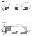
- FIG. 1is a schematic side view of a tubular, knitted sleeve shown in accordance with one aspect of the invention, with the sleeve shown in a shrunken assembled state about an elongate member to be protected;
- FIG. 2is a side view of a knitted sleeve in accordance with one aspect of the invention shown in an “as knit”, non-shrunken assembly state;
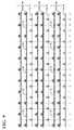
- FIG. 3is a knitting stitch pattern in accordance with one aspect of the invention used to knit a sleeve as schematically shown in FIGS. 1 and 2 ;
- FIG. 4is a diagram of a knitted structure formed from the knitting stitch pattern of FIG. 3 ;
- FIG. 5is a knitting stitch pattern in accordance with another aspect of the invention used to knit a sleeve as schematically shown in FIGS. 1 and 2 ;
- FIG. 6is a diagram of a knitted structure formed from the knitting stitch pattern of FIG. 5 ;
- FIG. 7is an enlarged, fragmentary view of a portion of the knitted structure of FIG. 4 ;
- FIG. 7Ais a diagrammatic representation of the fragmentary knitted structure of FIG. 7 ;
- FIG. 7Bis a knitting stitch pattern of the fragmentary knitted structure of FIG. 7 ;
- FIG. 8is a schematic cross-sectional end view of a knitted sleeve constructed in accordance with one aspect of the invention showing radially inwardly extending cushions of knitted yarn that provide enhanced impact protection to an elongate member being protected within a cavity of the sleeve;
- FIG. 9is a knitting stitch pattern in accordance with another aspect of the invention used to knit a sleeve as schematically shown in FIGS. 1 and 2 ;
- FIG. 10is a diagram of a knitted structure formed from the knitting stitch pattern of FIG. 9 ;
- FIG. 11is a diagram similar to FIG. 4 of a knitted structure for a sleeve constructed in accordance with another aspect of the invention.
- FIGS. 1 and 2schematically illustrate a knitted protective tubular sleeve, referred to hereafter as sleeve 10 , constructed in accordance with one aspect of the disclosure.
- the sleeve 10is shown disposed about an elongate member 12 to be protected, with the sleeve 10 shown in a second, diametrically shrunken, fully assembled state about the elongate member 12 , referred to hereafter as, assembled state, shrunken state and/or second state.
- assembled stateshrunken state and/or second state.
- the sleeve 10is shown in an “as knit”, first, diametrically enlarged, non-shrunken assembly state, referred to hereafter as, assembly state, non-shrunken state and/or first state.
- the sleeve 10has an elongate, knitted wall 14 having a circumferentially continuous, tubular outer periphery, also referred to as outer surface 15 , and an inner surface 16 bounding an inner cavity 17 extending along a central longitudinal axis 18 between opposite open ends 20 , 22 .
- the wall 14includes at least two different types of yarn, including at least one highly shrinkable yarn 24 and at least one non-shrinkable, or substantially non-shrinkable yarn, referred to hereafter as non-shrinkable yarn 26 .
- substantially non-shrinkablewhat is meant is that the yarn 26 is not marketed or otherwise considered by one skilled in the art as being shrinkable, and that although it may shrink somewhat, such as between about 1-10% of its original length, this is nowhere near the extent of shrinkage as provided by the highly shrinkable yarn 24 , which shrinks about 20% or more of its original length.
- the wall 14upon knitting the sleeve 10 , has both circumferentially extending knit courses 28 of the shrinkable yarn 24 and circumferentially extending knit courses 30 of the non-shrinkable yarn 26 interlinked via knit stitches with one another.
- the elongate member 12can be easily disposed through the cavity 17 , such as wires, a wire harness, or conduit, for example, while the sleeve 10 is in the enlarged, non-shrunken first state.
- the wall 14being non-shrunken “as knit”, the elongate member 12 is able to be easily fed through the cavity 17 of the sleeve 10 without getting snagged or caught up.
- the single sleeve 10is useful to be assembled over a wide range of elongate member diameters without having to have a separate sleeve for each different diameter elongate member 12 .
- the sleeve 10is formed with the wall 14 being enlarged and stretchable such that the cavity 17 is suitably sized and can be enlarged diametrically to readily receive the elongate member 12 therethrough.
- the ratio between the first, “as knit” diameter and the second, as shrunken diameteris at least 1.5:1, and preferably 2:1 or greater, and more preferably 3:1 or greater, and as high as about 10:1 or greater.
- the elongate member 12can still be easily inserted through the cavity 17 of the sleeve 10 while the cavity 17 is in the enlarged, non-shrunken first state.
- the wall 14can be activated to shrink into close fit, snug abutting relation about the elongate member 12 ( FIG. 1 ) via selected application of at least one of heat, fluid, and ultraviolet radiation, depending on the type of shrinkable yarn 24 used.
- the sleeve 10becomes fixed and located about the elongate member 12 against axial dislocation without need of secondary fixation mechanisms, thereby doing away for the need for clamps, straps, tape, or the like.
- the knit wall 14becomes densified upon being shrunken, and thus, the protective attributes of the wall 14 , such as impact resistance, abrasion resistance, impermeability, among other things, are greatly increased.
- the densitycan increase from a first density in the non-shrunken state to a second density in the shrunken state by about 2 times or greater, and in one sample, the density increased from 169 kg/m 3 to 486 kg/m 3 , by way of example and without limitation.
- the thickness and outer envelop of the wall 14is minimized, thereby being useful in tight areas.
- the finish thickness of the wall 14was about 3.4 mm, by way of example and without limitation.
- the shrinkable yarn 24can be provided as either a multifilament and/or monofilament. Further, the shrinkable yarn 24 can be provided having a denier ranging between about 50 to 10000.
- the non-shrinkable or substantially non-shrinkable yarn 26can be provided as a multifilament(s) and/or monofilament(s) of at least one or more of PET, nylon, PP, PE, PPS, PEEK, and Nomex material yarn(s).
- the denier of the non-shrinkable yarn 26can range from about 50 to 10000. It has been found that relatively bulky multifilaments provide the increased loft to further facilitate dampening impact forces, while also enhancing flexibility of the sleeve 10 .
- the number of yarn ends, including shrinkable and non-shrinkable yarns 24 , 26can be adjusted as desired for the intended application.
- the wall 14 of a sleeve 10constructed in accordance with one aspect of the disclosure, was knit with shrinkable and non-shrinkable yarns 24 , 26 , with the shrinkable yarn(s) 24 being knit in an interlock stitch pattern and the non-shrinkable yarn(s) knit in an ottoman stitch pattern ( FIG. 3 ), resulting the knit structure as shown in FIG. 4 .
- FIGS. 3 and 4As shown in FIGS.
- the shrinkable yarn 24can be knit in a plurality of circumferentially extending courses, shown as pairs of immediately adjacent courses 28 , with each pair, also referred to as group, of courses 28 of shrinkable yarn 24 being spaced from one another by a plurality of courses 30 of non-shrinkable yarn 26 , shown, by way of example and without limitation, as three courses 30 .
- the shrinkable yarn 24was provided as a 0.30 mm cross-linked polyethylene monofilament and the non-shrinkable yarn 26 was provided as a 600 denier, air texturized polyethylene terephthalate (PET) multifilament, both by way of example and without limitation.
- PETpolyethylene terephthalate
- the wall 14had a non-shrunk density of about 169 kg/m 3 , and after shrinking the sleeve 10 , the wall 14 had a density of about 486 kg/m 3 , with a finished, shrunken inner diameter of about 10 mm, by way of example and without limitation.
- the knittingcan be performed on any suitable knitting machine capable of forming a circumferentially continuous wall, such as a flat-bed knitting machine or via a circular knitting machine, by way of example and without limitation.
- the shrinkable yarn 24was knit on one of either even needles or odd needles, shown as being knit on each even needle within each course 28 in which the shrinkable 24 yarn is knit, by way of example and without limitation.
- the non-shrinkable yarn 26was knit on the other of the even needles or odd needles, shown as being knit on the odd needles, by way of example and without limitation.
- the non-shrinkable yarn 26 within at least one of the circumferentially extending courses 30 of each group of three courses 30skips at least one needle (not looped).
- the non-shrinkable yarn 26 in the middle course 30 within each group of three courses 30is shown as being looped about alternating odd needles (3, 7, 11 . . . ) and skipping every other odd needle (5, 9, 13 . . . ), thereby forming floats 32 of the non-shrinkable yarn 26 over the skipped needles.
- the resulting knitted structureis shown in FIG. 4
- an enlarged view of a section of the structure of the non-shrinkable yarn 26is shown in FIG. 7 , with a diagrammatic view of the stitch pattern being shown in FIGS. 7A and 7B , as will be readily understood by one possessing ordinary skill in the knitting art.
- FIG. 7a diagrammatic view of the stitch pattern being shown in FIGS. 7A and 7B , as will be readily understood by one possessing ordinary skill in the knitting art.
- the floats 32are formed by the middle non-shrinkable yarn 26 (number 2 of the three yarns 1, 2, 3) along the inner surface 16 of the wall 14 , with the floats 32 extending in the circumferential direction CD.
- the floats 32upon shrinking the sleeve 10 about the elongate member 12 and causing the wall 14 to be constricted circumferentially into a reduced diameter, snug fit with the elongate member 12 via activation of the shrinkable yarn 24 via application of heat, liquid, ultraviolet radiation, or pressure (depending on the type of heat-shrinkable yarn used), bulge and extend radially inwardly into abutment with an outer surface of the elongate member 12 , as shown schematically in FIG.
- the bulged floats 32form individual radially inwardly extending, lofted pillows or cushions, and referred to hereafter as dampeners 34 , which function to greatly diminish the transference of impact forces to the elongate member 12 , while also acting to dampen vibration. Accordingly, the elongate member 12 is surrounded about its circumference by the plurality of bulged dampeners 34 , and thus, the elongate member 12 is greatly protected against external impact forces and against sources of vibration.
- FIGS. 5 and 6wherein similar reference numerals as used above are used to indicate like features, offset by a factor of 100 wherein appropriate to indicate a difference embodiment, a wall 114 of a sleeve 110 , constructed in accordance with another aspect of the invention, was knit similarly that described above with regard to FIGS. 3 and 4 , with shrinkable yarns 24 knit in an interlock stitch pattern and the non-shrinkable yarns 26 knit in an ottoman stitch pattern ( FIG. 5 ), resulting the knit structure as shown in FIG. 6 .
- the shrinkable yarn 24was knit the same as discussed above, namely, in a plurality of circumferentially extending courses, shown as pairs of immediately adjacent courses 28 , with each pair of courses 28 of shrinkable yarn 24 being spaced from one another by the a plurality of courses 30 of non-shrinkable yarn 26 .
- the plurality of courses 30 of non-shrinkable yarn 26rather than being knit in groups of three courses, was knit in groups containing 4 courses 30 .
- the non-shrinkable yarn 26 within at least one course 30 within each group of four courses 30skips at least one or more needles.
- the non-shrinkable yarn 26 in the middle two courses 30 within each group of four courses 30is shown as being looped about alternating odd needles (3, 7, 11 . . . ) and skipping every other odd needle (5, 9, 13 . . . ), thereby forming floats 32 of the non-shrinkable yarn 26 over the skipped needles.
- the resulting knitted structureis shown in FIG. 6 , wherein the floats 32 within a common group of four non-shrinkable yarns 26 are formed in immediately adjacent relation one another, with the adjacent floats 32 being aligned axially with one another along a lengthwise extending direction along the longitudinal axis 18 .
- the floats 32can be positioned as desired, depending on the particular knit stitch patter used, and thus, the floats 32 within each group could be staggered circumferentially relative to one another, rather than being axially aligned, if desired. Otherwise, the knit wall 114 of the embodiment of FIGS. 5 and 6 is the same as discussed above, whereupon the floats 32 form radially inwardly extending dampeners 34 upon shrinking the wall 114 .
- a wall 214 of a sleeve 210was knit similarly that described above with regard to FIGS. 3 and 4 , with shrinkable yarns 24 ; however, rather than knitting the shrinkable yarns 24 in an interlock stitch pattern, the shrinkable yarns 24 were knit in a jersey stitch pattern.
- the non-shrinkable yarns 26were knit in an ottoman stitch pattern, resulting in the knit structure as shown in FIG. 10 .
- the shrinkable yarn 24was knit in single courses 28 , with each course 28 of shrinkable yarn 24 being spaced from one another by the a plurality of courses 30 of non-shrinkable yarn 26 , shown as a pair of courses 30 , by way of example and without limitation.
- the non-shrinkable yarn 26 within at least one of the courses 30 of each group of courses 30skips at least one needle.
- one of the pair of non-shrinkable yarns 26 in each group or plurality of course 30is shown as being looped about alternating odd needles (1, 5, 9, 13 . . . ) and skipping every other odd needle (3, 7, 11 . . .
- FIG. 10The resulting knitted structure of the wall 214 is shown in FIG. 10 .
- This embodimenthas been found particularly suitable for construction on a circular knitting machine, though other embodiments are contemplated herein, for knitting on both a flat-bed knitting machine or circular knitting machine.
- a sleeve wall 314 constructed in accordance with another aspect of the disclosureis shown, wherein similar reference numerals as used above are used to indicate like features, offset by a factor of 300 wherein appropriate to indicate a different embodiment.
- shrinkable yarn 24 and the non-shrinkable yarn 26can further include a low melt yarn 36 .
- the low melt yarn 36can be knit with the shrinkable yarn 24 and/or the non-shrinkable yarn 26 , and is shown as being served or twisted with the shrinkable yarn 24 , though it can also be served or twisted with the non-shrinkable yarn 26 .
- the low melt yarn 36has a melt temperature that is less than the melt and shrinking temperature of the shrinkable yarn 24 and less than the melt temperature of the non-shrinkable yarn 26 , and thus, can be readily melted, at least in part, without adversely affecting the performance of the yarns 24 , 26 , and further, without activating shrinkage of the shrinkable yarn 24 .
- the low melt yarn 36can be melted, and thus, bonded with the abutting shrinkable yarn 24 and the non-shrinkable yarn 26 , thereby acting to prevent end fray.
- a hot blade, wire or knifeby way of example and without limitation, can be used in a cutting operation of manufacture to cut the sleeve wall 314 to length, and thus, during the cutting operation, the low melt yarn 36 is simultaneously melted, thereby acting to prevent end fray without causing the shrinkable yarn 24 to be shrunk.
Landscapes
- Engineering & Computer Science (AREA)
- Textile Engineering (AREA)
- Architecture (AREA)
- Civil Engineering (AREA)
- Structural Engineering (AREA)
- Mechanical Engineering (AREA)
- Knitting Of Fabric (AREA)
- Gloves (AREA)
- Professional, Industrial, Or Sporting Protective Garments (AREA)
Abstract
Description
Claims (21)
Priority Applications (7)
| Application Number | Priority Date | Filing Date | Title |
|---|---|---|---|
| US15/684,875US10415162B2 (en) | 2016-08-24 | 2017-08-23 | Impact resistant, shrinkable knitted tubular sleeve and method of construction thereof |
| KR1020197007177AKR102404351B1 (en) | 2016-08-24 | 2017-08-24 | Impact resistant, shrinkable knitted tubular sleeve and manufacturing method thereof |
| BR112019003664-4ABR112019003664A2 (en) | 2016-08-24 | 2017-08-24 | impact resistant shrink sleeve tubular sleeve and method of construction |
| CN201780065708.7ACN109863263B (en) | 2016-08-24 | 2017-08-24 | Impact resistant, collapsible knit tubular sleeve and method of construction thereof |
| JP2019510934AJP7066678B2 (en) | 2016-08-24 | 2017-08-24 | Impact resistant and shrinkable woven tubular sleeve and how to build it |
| EP17761721.4AEP3504366B1 (en) | 2016-08-24 | 2017-08-24 | Impact resistant, shrinkable knitted tubular sleeve and method of construction thereof |
| PCT/US2017/048304WO2018039399A1 (en) | 2016-08-24 | 2017-08-24 | Impact resistant, shrinkable knitted tubular sleeve and method of construction thereof |
Applications Claiming Priority (2)
| Application Number | Priority Date | Filing Date | Title |
|---|---|---|---|
| US201662378992P | 2016-08-24 | 2016-08-24 | |
| US15/684,875US10415162B2 (en) | 2016-08-24 | 2017-08-23 | Impact resistant, shrinkable knitted tubular sleeve and method of construction thereof |
Publications (2)
| Publication Number | Publication Date |
|---|---|
| US20180057977A1 US20180057977A1 (en) | 2018-03-01 |
| US10415162B2true US10415162B2 (en) | 2019-09-17 |
Family
ID=61241784
Family Applications (1)
| Application Number | Title | Priority Date | Filing Date |
|---|---|---|---|
| US15/684,875ActiveUS10415162B2 (en) | 2016-08-24 | 2017-08-23 | Impact resistant, shrinkable knitted tubular sleeve and method of construction thereof |
Country Status (7)
| Country | Link |
|---|---|
| US (1) | US10415162B2 (en) |
| EP (1) | EP3504366B1 (en) |
| JP (1) | JP7066678B2 (en) |
| KR (1) | KR102404351B1 (en) |
| CN (1) | CN109863263B (en) |
| BR (1) | BR112019003664A2 (en) |
| WO (1) | WO2018039399A1 (en) |
Families Citing this family (8)
| Publication number | Priority date | Publication date | Assignee | Title |
|---|---|---|---|---|
| CN106037119A (en)* | 2016-07-25 | 2016-10-26 | 信泰(福建)科技有限公司 | Shoe upper manufacture method and integral woven shoe upper |
| US11517062B2 (en)* | 2018-05-15 | 2022-12-06 | Brian Timlick | Helmet with unique impact absorption and redirection features |
| WO2020140028A1 (en)* | 2018-12-28 | 2020-07-02 | Flex Ltd. | Plaited low-melt yarn for adhering fabric |
| US11920266B2 (en)* | 2019-09-10 | 2024-03-05 | Federal-Mogul Powertrain Llc | Convolute woven sleeve and method of construction thereof |
| US11686022B2 (en) | 2020-02-11 | 2023-06-27 | Federal-Mogul Powertrain Llc | Impact resistant, wrappable, corrugated, multilayered woven sleeve and method of construction thereof |
| WO2021179278A1 (en) | 2020-03-13 | 2021-09-16 | 深圳市骏鼎达新材料股份有限公司 | Protection pipe |
| KR102592189B1 (en)* | 2023-02-27 | 2023-10-20 | 안켐 주식회사 | Textile sleeve having multi layer |
| WO2025128970A1 (en)* | 2023-12-13 | 2025-06-19 | Nike Innovate C.V. | Interlaced knitted component and methods of manufacture |
Citations (11)
| Publication number | Priority date | Publication date | Assignee | Title |
|---|---|---|---|---|
| US2738566A (en) | 1955-05-17 | 1956-03-20 | Carter William Co | Puckered knit fabric and method of producing same |
| US3685316A (en)* | 1966-06-07 | 1972-08-22 | Courtaulds Ltd | Knitting process |
| US5366771A (en) | 1989-09-29 | 1994-11-22 | Nv Raychem Sa | Recoverable fabric sleeve |
| US20030089971A1 (en) | 2001-11-14 | 2003-05-15 | Akers Jessica L. | Knit convolute protective sleeve |
| US20070240896A1 (en) | 2006-04-17 | 2007-10-18 | Ott Donald C Jr | Protective sleeve assembly having an integral closure member and methods of manufacture and use thereof |
| DE102007023062A1 (en)* | 2007-05-16 | 2008-11-20 | Iprotex Gmbh & Co. Kg | Method for producing a fabric and tissue produced thereby |
| US7647946B2 (en) | 2006-02-28 | 2010-01-19 | Federal Mogul Systems Protection | Sheath for protection of a pipe against impacts, in particular for fuel pipes |
| US20110177294A1 (en) | 2010-01-19 | 2011-07-21 | Mmi-Ipco, Llc | Composite textile fabrics |
| US20130224408A1 (en) | 2012-02-23 | 2013-08-29 | Cassie M. Malloy | Knit sleeve for an oil dip stick tube, combination thereof, method of construction thereof and method of dampening the vibration of an oil dip stick tube |
| US20160076176A1 (en) | 2014-09-17 | 2016-03-17 | Myant Capital Partners Inc. | Seamless silhouette with engineered insulation property |
| US20180002843A1 (en)* | 2016-07-01 | 2018-01-04 | Federal-Mogul Powertrain Llc | Circumferentially continuous and constrictable textile sleeve and method of construction thereof |
Family Cites Families (15)
| Publication number | Priority date | Publication date | Assignee | Title |
|---|---|---|---|---|
| GB1493007A (en)* | 1975-05-12 | 1977-11-23 | Goodyear Tire & Rubber | Hose structure |
| SU1026825A1 (en)* | 1979-12-25 | 1983-07-07 | Предприятие П/Я А-7113 | Filtering material |
| US5952067A (en)* | 1996-12-02 | 1999-09-14 | A&P Technology, Inc. | Braided structure having uncrimped strands |
| GB0131016D0 (en)* | 2001-12-27 | 2002-02-13 | Voith Fabrics Heidenheim Gmbh | Roll covers |
| DE10212922A1 (en)* | 2002-03-22 | 2003-10-16 | Iprotex Gmbh & Co Kg | Braided tubular fabric, to shroud cable splicings and the like, has intersecting monofilament and/or multifilament groups with some filaments of a high shrinkage material |
| US7395680B2 (en)* | 2004-07-20 | 2008-07-08 | Federal Mogul Worldwide, Inc. | Self-curling knitted sleeve and method of fabrication |
| JP2009024287A (en)* | 2007-07-20 | 2009-02-05 | Cordon Co Ltd | Sound absorbing sleeve and method for producing the same |
| JP3166050U (en)* | 2010-12-03 | 2011-02-17 | 藤井株式会社 | Elastic cylindrical pillowcase fabric |
| JP5886311B2 (en)* | 2010-12-08 | 2016-03-16 | フェデラル−モーグル パワートレイン インコーポレイテッドFederal−Mogul Powertrain, Inc. | Fiber sleeve having protective coating and method for producing the same |
| DE102013203538A1 (en)* | 2013-03-01 | 2014-09-04 | Fränkische Industrial Pipes GmbH & Co. KG | Knitted shrink tube and method for its production |
| US10132012B2 (en)* | 2013-03-14 | 2018-11-20 | Federal-Mogul Powertrain Llc | End-fray resistant heat-shrinkable woven sleeve, assembly therewith and methods of construction thereof |
| JP2014231665A (en)* | 2013-04-30 | 2014-12-11 | 株式会社島精機製作所 | Multilayer knitted fabric having projections and recesses |
| US10202714B2 (en)* | 2014-10-30 | 2019-02-12 | Federal-Mogul Powertrain Llc | Braided textile sleeve with self-sustaining expanded and contracted states and method of construction thereof |
| JP6607819B2 (en) | 2016-04-01 | 2019-11-20 | 株式会社オオカワニット | Circular knitted tubular structure, manufacturing method thereof and manufacturing apparatus thereof |
| JP2017212818A (en) | 2016-05-26 | 2017-11-30 | 株式会社オートネットワーク技術研究所 | Wire protection member, wire with wire protection member, and method of manufacturing wire with wire protection member |
- 2017
- 2017-08-23USUS15/684,875patent/US10415162B2/enactiveActive
- 2017-08-24JPJP2019510934Apatent/JP7066678B2/enactiveActive
- 2017-08-24WOPCT/US2017/048304patent/WO2018039399A1/ennot_activeCeased
- 2017-08-24KRKR1020197007177Apatent/KR102404351B1/enactiveActive
- 2017-08-24EPEP17761721.4Apatent/EP3504366B1/enactiveActive
- 2017-08-24CNCN201780065708.7Apatent/CN109863263B/enactiveActive
- 2017-08-24BRBR112019003664-4Apatent/BR112019003664A2/ennot_activeApplication Discontinuation
Patent Citations (11)
| Publication number | Priority date | Publication date | Assignee | Title |
|---|---|---|---|---|
| US2738566A (en) | 1955-05-17 | 1956-03-20 | Carter William Co | Puckered knit fabric and method of producing same |
| US3685316A (en)* | 1966-06-07 | 1972-08-22 | Courtaulds Ltd | Knitting process |
| US5366771A (en) | 1989-09-29 | 1994-11-22 | Nv Raychem Sa | Recoverable fabric sleeve |
| US20030089971A1 (en) | 2001-11-14 | 2003-05-15 | Akers Jessica L. | Knit convolute protective sleeve |
| US7647946B2 (en) | 2006-02-28 | 2010-01-19 | Federal Mogul Systems Protection | Sheath for protection of a pipe against impacts, in particular for fuel pipes |
| US20070240896A1 (en) | 2006-04-17 | 2007-10-18 | Ott Donald C Jr | Protective sleeve assembly having an integral closure member and methods of manufacture and use thereof |
| DE102007023062A1 (en)* | 2007-05-16 | 2008-11-20 | Iprotex Gmbh & Co. Kg | Method for producing a fabric and tissue produced thereby |
| US20110177294A1 (en) | 2010-01-19 | 2011-07-21 | Mmi-Ipco, Llc | Composite textile fabrics |
| US20130224408A1 (en) | 2012-02-23 | 2013-08-29 | Cassie M. Malloy | Knit sleeve for an oil dip stick tube, combination thereof, method of construction thereof and method of dampening the vibration of an oil dip stick tube |
| US20160076176A1 (en) | 2014-09-17 | 2016-03-17 | Myant Capital Partners Inc. | Seamless silhouette with engineered insulation property |
| US20180002843A1 (en)* | 2016-07-01 | 2018-01-04 | Federal-Mogul Powertrain Llc | Circumferentially continuous and constrictable textile sleeve and method of construction thereof |
Non-Patent Citations (1)
| Title |
|---|
| International Search Report, dated Dec. 12, 2017 (PCT/US2017/048304). |
Also Published As
| Publication number | Publication date |
|---|---|
| EP3504366A1 (en) | 2019-07-03 |
| JP7066678B2 (en) | 2022-05-13 |
| EP3504366B1 (en) | 2022-06-15 |
| CN109863263B (en) | 2022-01-28 |
| US20180057977A1 (en) | 2018-03-01 |
| KR20190039241A (en) | 2019-04-10 |
| BR112019003664A2 (en) | 2019-05-21 |
| JP2019525023A (en) | 2019-09-05 |
| CN109863263A (en) | 2019-06-07 |
| WO2018039399A1 (en) | 2018-03-01 |
| KR102404351B1 (en) | 2022-05-31 |
Similar Documents
| Publication | Publication Date | Title |
|---|---|---|
| US10415162B2 (en) | Impact resistant, shrinkable knitted tubular sleeve and method of construction thereof | |
| US11332859B2 (en) | Impact resistant, shrinkable braided tubular sleeve and method of construction thereof | |
| US11180872B2 (en) | Impact resistant, shrinkable woven tubular sleeve and method of construction thereof | |
| US10132012B2 (en) | End-fray resistant heat-shrinkable woven sleeve, assembly therewith and methods of construction thereof | |
| EP2964820B1 (en) | Heat-shrunk textile sleeve with extended electro-functional yarn and method of construction thereof | |
| US11168415B2 (en) | Circumferentially continuous and constrictable textile sleeve and method of construction thereof | |
| US10393307B2 (en) | Multi-cavity, shrinkable sleeve and method of construction thereof | |
| US11421356B2 (en) | Braided, reflective textile sleeve and method of construction thereof | |
| US20200232132A1 (en) | Braided protective sleeve with heat-shrinkable yarns and method of construction thereof | |
| US20250019874A1 (en) | Multilayered, braided tubular sleeve and method of construction thereof | |
| WO2025015270A1 (en) | Multilayered, braided tubular sleeve and method of construction thereof |
Legal Events
| Date | Code | Title | Description |
|---|---|---|---|
| AS | Assignment | Owner name:BANK OF AMERICA, N.A., AS COLLATERAL TRUSTEE, MICHIGAN Free format text:CONFIRMATORY GRANT OF SECURITY INTERESTS IN UNITED STATES PATENTS;ASSIGNORS:FEDERAL-MOGUL LLC;FEDERAL-MOGUL MOTORPARTS LLC;FEDERAL MOGUL POWERTRAIN LLC;AND OTHERS;REEL/FRAME:045822/0454 Effective date:20180328 Owner name:BANK OF AMERICA, N.A., AS COLLATERAL TRUSTEE, MICH Free format text:CONFIRMATORY GRANT OF SECURITY INTERESTS IN UNITED STATES PATENTS;ASSIGNORS:FEDERAL-MOGUL LLC;FEDERAL-MOGUL MOTORPARTS LLC;FEDERAL MOGUL POWERTRAIN LLC;AND OTHERS;REEL/FRAME:045822/0454 Effective date:20180328 | |
| AS | Assignment | Owner name:WILMINGTON TRUST, NATIONAL ASSOCIATION, AS COLLATERAL TRUSTEE, MINNESOTA Free format text:CONFIRMATORY GRANT OF SECURITY INTERESTS IN UNITED STATES PATENTS;ASSIGNORS:TENNECO INC.;TENNECO AUTOMOTIVE OPERATING COMPANY INC.;TENNECO INTERNATIONAL HOLDING CORP.;AND OTHERS;REEL/FRAME:047223/0001 Effective date:20181001 Owner name:WILMINGTON TRUST, NATIONAL ASSOCIATION, AS COLLATE Free format text:CONFIRMATORY GRANT OF SECURITY INTERESTS IN UNITED STATES PATENTS;ASSIGNORS:TENNECO INC.;TENNECO AUTOMOTIVE OPERATING COMPANY INC.;TENNECO INTERNATIONAL HOLDING CORP.;AND OTHERS;REEL/FRAME:047223/0001 Effective date:20181001 | |
| AS | Assignment | Owner name:FEDERAL MOGUL POWERTRAIN LLC, MICHIGAN Free format text:RELEASE BY SECURED PARTY;ASSIGNOR:BANK OF AMERICA, N.A., AS COLLATERAL TRUSTEE;REEL/FRAME:047276/0720 Effective date:20181001 Owner name:FEDERAL-MOGUL MOTORPARTS LLC, MICHIGAN Free format text:RELEASE BY SECURED PARTY;ASSIGNOR:BANK OF AMERICA, N.A., AS COLLATERAL TRUSTEE;REEL/FRAME:047276/0720 Effective date:20181001 Owner name:FEDERAL-MOGUL LLC, MICHIGAN Free format text:RELEASE BY SECURED PARTY;ASSIGNOR:BANK OF AMERICA, N.A., AS COLLATERAL TRUSTEE;REEL/FRAME:047276/0720 Effective date:20181001 Owner name:FEDERAL-MOGUL IGNITION COMPANY, MICHIGAN Free format text:RELEASE BY SECURED PARTY;ASSIGNOR:BANK OF AMERICA, N.A., AS COLLATERAL TRUSTEE;REEL/FRAME:047276/0720 Effective date:20181001 | |
| AS | Assignment | Owner name:WILMINGTON TRUST, NATIONAL ASSOCIATION, AS CO-COLLATERAL TRUSTEE, SUCCESSOR COLLATERAL TRUSTEE, MINNESOTA Free format text:COLLATERAL TRUSTEE RESIGNATION AND APPOINTMENT, JOINDER, ASSUMPTION AND DESIGNATION AGREEMENT;ASSIGNOR:BANK OF AMERICA, N.A., AS CO-COLLATERAL TRUSTEE AND RESIGNING COLLATERAL TRUSTEE;REEL/FRAME:047630/0661 Effective date:20181001 Owner name:WILMINGTON TRUST, NATIONAL ASSOCIATION, AS CO-COLL Free format text:COLLATERAL TRUSTEE RESIGNATION AND APPOINTMENT, JOINDER, ASSUMPTION AND DESIGNATION AGREEMENT;ASSIGNOR:BANK OF AMERICA, N.A., AS CO-COLLATERAL TRUSTEE AND RESIGNING COLLATERAL TRUSTEE;REEL/FRAME:047630/0661 Effective date:20181001 | |
| STPP | Information on status: patent application and granting procedure in general | Free format text:RESPONSE TO NON-FINAL OFFICE ACTION ENTERED AND FORWARDED TO EXAMINER | |
| AS | Assignment | Owner name:FEDERAL-MOGUL POWERTRAIN LLC, MICHIGAN Free format text:ASSIGNMENT OF ASSIGNORS INTEREST;ASSIGNORS:ZHANG, ZHONG HUAI;QIU, XIAODAN;LUDY, LINWOOD;AND OTHERS;REEL/FRAME:049023/0252 Effective date:20170822 | |
| STPP | Information on status: patent application and granting procedure in general | Free format text:NOTICE OF ALLOWANCE MAILED -- APPLICATION RECEIVED IN OFFICE OF PUBLICATIONS | |
| STPP | Information on status: patent application and granting procedure in general | Free format text:AWAITING TC RESP., ISSUE FEE NOT PAID | |
| STPP | Information on status: patent application and granting procedure in general | Free format text:NOTICE OF ALLOWANCE MAILED -- APPLICATION RECEIVED IN OFFICE OF PUBLICATIONS | |
| STPP | Information on status: patent application and granting procedure in general | Free format text:PUBLICATIONS -- ISSUE FEE PAYMENT VERIFIED | |
| STCF | Information on status: patent grant | Free format text:PATENTED CASE | |
| AS | Assignment | Owner name:WILMINGTON TRUST, NATIONAL ASSOCIATION, MINNESOTA Free format text:SECURITY AGREEMENT;ASSIGNORS:TENNECO INC.;THE PULLMAN COMPANY;FEDERAL-MOGUL IGNITION LLC;AND OTHERS;REEL/FRAME:054555/0592 Effective date:20201130 | |
| AS | Assignment | Owner name:WILMINGTON TRUST, NATIONAL ASSOCIATION, MINNESOTA Free format text:SECURITY AGREEMENT;ASSIGNORS:TENNECO INC.;TENNECO AUTOMOTIVE OPERATING COMPANY INC.;THE PULLMAN COMPANY;AND OTHERS;REEL/FRAME:055626/0065 Effective date:20210317 | |
| AS | Assignment | Owner name:FEDERAL-MOGUL PRODUCTS US LLC, MICHIGAN Free format text:RELEASE BY SECURED PARTY;ASSIGNOR:WILMINGTON TRUST, NATIONAL ASSOCIATION;REEL/FRAME:061975/0218 Effective date:20221117 Owner name:FEDERAL-MOGUL FINANCING CORPORATION, MICHIGAN Free format text:RELEASE BY SECURED PARTY;ASSIGNOR:WILMINGTON TRUST, NATIONAL ASSOCIATION;REEL/FRAME:061975/0218 Effective date:20221117 Owner name:FEDERAL-MOGUL FILTRATION LLC, MICHIGAN Free format text:RELEASE BY SECURED PARTY;ASSIGNOR:WILMINGTON TRUST, NATIONAL ASSOCIATION;REEL/FRAME:061975/0218 Effective date:20221117 Owner name:BECK ARNLEY HOLDINGS LLC, MICHIGAN Free format text:RELEASE BY SECURED PARTY;ASSIGNOR:WILMINGTON TRUST, NATIONAL ASSOCIATION;REEL/FRAME:061975/0218 Effective date:20221117 Owner name:FEDERAL-MOGUL SEVIERVILLE, LLC, MICHIGAN Free format text:RELEASE BY SECURED PARTY;ASSIGNOR:WILMINGTON TRUST, NATIONAL ASSOCIATION;REEL/FRAME:061975/0218 Effective date:20221117 Owner name:FEDERAL-MOGUL VALVE TRAIN INTERNATIONAL LLC, MICHIGAN Free format text:RELEASE BY SECURED PARTY;ASSIGNOR:WILMINGTON TRUST, NATIONAL ASSOCIATION;REEL/FRAME:061975/0218 Effective date:20221117 Owner name:F-M TSC REAL ESTATE HOLDINGS LLC, MICHIGAN Free format text:RELEASE BY SECURED PARTY;ASSIGNOR:WILMINGTON TRUST, NATIONAL ASSOCIATION;REEL/FRAME:061975/0218 Effective date:20221117 Owner name:F-M MOTORPARTS TSC LLC, MICHIGAN Free format text:RELEASE BY SECURED PARTY;ASSIGNOR:WILMINGTON TRUST, NATIONAL ASSOCIATION;REEL/FRAME:061975/0218 Effective date:20221117 Owner name:FEDERAL-MOGUL CHASSIS LLC, MICHIGAN Free format text:RELEASE BY SECURED PARTY;ASSIGNOR:WILMINGTON TRUST, NATIONAL ASSOCIATION;REEL/FRAME:061975/0218 Effective date:20221117 Owner name:FEDERAL-MOGUL MOTORPARTS LLC, MICHIGAN Free format text:RELEASE BY SECURED PARTY;ASSIGNOR:WILMINGTON TRUST, NATIONAL ASSOCIATION;REEL/FRAME:061975/0218 Effective date:20221117 Owner name:FEDERAL-MOGUL IGNITION LLC, MICHIGAN Free format text:RELEASE BY SECURED PARTY;ASSIGNOR:WILMINGTON TRUST, NATIONAL ASSOCIATION;REEL/FRAME:061975/0218 Effective date:20221117 Owner name:FEDERAL-MOGUL PISTON RINGS, LLC, MICHIGAN Free format text:RELEASE BY SECURED PARTY;ASSIGNOR:WILMINGTON TRUST, NATIONAL ASSOCIATION;REEL/FRAME:061975/0218 Effective date:20221117 Owner name:FEDERAL-MOGUL POWERTRAIN IP LLC, MICHIGAN Free format text:RELEASE BY SECURED PARTY;ASSIGNOR:WILMINGTON TRUST, NATIONAL ASSOCIATION;REEL/FRAME:061975/0218 Effective date:20221117 Owner name:FEDERAL-MOGUL POWERTRAIN LLC, MICHIGAN Free format text:RELEASE BY SECURED PARTY;ASSIGNOR:WILMINGTON TRUST, NATIONAL ASSOCIATION;REEL/FRAME:061975/0218 Effective date:20221117 Owner name:MUZZY-LYON AUTO PARTS LLC, ILLINOIS Free format text:RELEASE BY SECURED PARTY;ASSIGNOR:WILMINGTON TRUST, NATIONAL ASSOCIATION;REEL/FRAME:061975/0218 Effective date:20221117 Owner name:FELT PRODUCTS MFG. CO. LLC, ILLINOIS Free format text:RELEASE BY SECURED PARTY;ASSIGNOR:WILMINGTON TRUST, NATIONAL ASSOCIATION;REEL/FRAME:061975/0218 Effective date:20221117 Owner name:FEDERAL-MOGUL WORLD WIDE LLC, MICHIGAN Free format text:RELEASE BY SECURED PARTY;ASSIGNOR:WILMINGTON TRUST, NATIONAL ASSOCIATION;REEL/FRAME:061975/0218 Effective date:20221117 Owner name:CARTER AUTOMOTIVE COMPANY LLC, ILLINOIS Free format text:RELEASE BY SECURED PARTY;ASSIGNOR:WILMINGTON TRUST, NATIONAL ASSOCIATION;REEL/FRAME:061975/0218 Effective date:20221117 Owner name:TMC TEXAS INC., ILLINOIS Free format text:RELEASE BY SECURED PARTY;ASSIGNOR:WILMINGTON TRUST, NATIONAL ASSOCIATION;REEL/FRAME:061975/0218 Effective date:20221117 Owner name:CLEVITE INDUSTRIES INC., OHIO Free format text:RELEASE BY SECURED PARTY;ASSIGNOR:WILMINGTON TRUST, NATIONAL ASSOCIATION;REEL/FRAME:061975/0218 Effective date:20221117 Owner name:TENNECO GLOBAL HOLDINGS INC., ILLINOIS Free format text:RELEASE BY SECURED PARTY;ASSIGNOR:WILMINGTON TRUST, NATIONAL ASSOCIATION;REEL/FRAME:061975/0218 Effective date:20221117 Owner name:THE PULLMAN COMPANY, OHIO Free format text:RELEASE BY SECURED PARTY;ASSIGNOR:WILMINGTON TRUST, NATIONAL ASSOCIATION;REEL/FRAME:061975/0218 Effective date:20221117 Owner name:TENNECO INTERNATIONAL HOLDING CORP., ILLINOIS Free format text:RELEASE BY SECURED PARTY;ASSIGNOR:WILMINGTON TRUST, NATIONAL ASSOCIATION;REEL/FRAME:061975/0218 Effective date:20221117 Owner name:TENNECO AUTOMOTIVE OPERATING COMPANY INC., ILLINOIS Free format text:RELEASE BY SECURED PARTY;ASSIGNOR:WILMINGTON TRUST, NATIONAL ASSOCIATION;REEL/FRAME:061975/0218 Effective date:20221117 Owner name:TENNECO INC., ILLINOIS Free format text:RELEASE BY SECURED PARTY;ASSIGNOR:WILMINGTON TRUST, NATIONAL ASSOCIATION;REEL/FRAME:061975/0218 Effective date:20221117 Owner name:DRIV AUTOMOTIVE INC., MICHIGAN Free format text:RELEASE BY SECURED PARTY;ASSIGNOR:WILMINGTON TRUST, NATIONAL ASSOCIATION;REEL/FRAME:061971/0156 Effective date:20221117 Owner name:FEDERAL-MOGUL CHASSIS LLC, MICHIGAN Free format text:RELEASE BY SECURED PARTY;ASSIGNOR:WILMINGTON TRUST, NATIONAL ASSOCIATION;REEL/FRAME:061971/0156 Effective date:20221117 Owner name:FEDERAL-MOGUL WORLD WIDE LLC, MICHIGAN Free format text:RELEASE BY SECURED PARTY;ASSIGNOR:WILMINGTON TRUST, NATIONAL ASSOCIATION;REEL/FRAME:061971/0156 Effective date:20221117 Owner name:FEDERAL-MOGUL MOTORPARTS LLC, MICHIGAN Free format text:RELEASE BY SECURED PARTY;ASSIGNOR:WILMINGTON TRUST, NATIONAL ASSOCIATION;REEL/FRAME:061971/0156 Effective date:20221117 Owner name:FEDERAL-MOGUL PRODUCTS US LLC, MICHIGAN Free format text:RELEASE BY SECURED PARTY;ASSIGNOR:WILMINGTON TRUST, NATIONAL ASSOCIATION;REEL/FRAME:061971/0156 Effective date:20221117 Owner name:FEDERAL-MOGUL POWERTRAIN LLC, MICHIGAN Free format text:RELEASE BY SECURED PARTY;ASSIGNOR:WILMINGTON TRUST, NATIONAL ASSOCIATION;REEL/FRAME:061971/0156 Effective date:20221117 Owner name:FEDERAL-MOGUL IGNITION LLC, MICHIGAN Free format text:RELEASE BY SECURED PARTY;ASSIGNOR:WILMINGTON TRUST, NATIONAL ASSOCIATION;REEL/FRAME:061971/0156 Effective date:20221117 Owner name:THE PULLMAN COMPANY, OHIO Free format text:RELEASE BY SECURED PARTY;ASSIGNOR:WILMINGTON TRUST, NATIONAL ASSOCIATION;REEL/FRAME:061971/0156 Effective date:20221117 Owner name:TENNECO AUTOMOTIVE OPERATING COMPANY INC., ILLINOIS Free format text:RELEASE BY SECURED PARTY;ASSIGNOR:WILMINGTON TRUST, NATIONAL ASSOCIATION;REEL/FRAME:061971/0156 Effective date:20221117 Owner name:TENNECO INC., ILLINOIS Free format text:RELEASE BY SECURED PARTY;ASSIGNOR:WILMINGTON TRUST, NATIONAL ASSOCIATION;REEL/FRAME:061971/0156 Effective date:20221117 Owner name:DRIV AUTOMOTIVE INC., MICHIGAN Free format text:RELEASE BY SECURED PARTY;ASSIGNOR:WILMINGTON TRUST, NATIONAL ASSOCIATION;REEL/FRAME:061975/0031 Effective date:20221117 Owner name:FEDERAL-MOGUL CHASSIS LLC, MICHIGAN Free format text:RELEASE BY SECURED PARTY;ASSIGNOR:WILMINGTON TRUST, NATIONAL ASSOCIATION;REEL/FRAME:061975/0031 Effective date:20221117 Owner name:FEDERAL-MOGUL WORLD WIDE LLC, MICHIGAN Free format text:RELEASE BY SECURED PARTY;ASSIGNOR:WILMINGTON TRUST, NATIONAL ASSOCIATION;REEL/FRAME:061975/0031 Effective date:20221117 Owner name:FEDERAL-MOGUL PRODUCTS US LLC, MICHIGAN Free format text:RELEASE BY SECURED PARTY;ASSIGNOR:WILMINGTON TRUST, NATIONAL ASSOCIATION;REEL/FRAME:061975/0031 Effective date:20221117 Owner name:FEDERAL-MOGUL POWERTRAIN LLC, MICHIGAN Free format text:RELEASE BY SECURED PARTY;ASSIGNOR:WILMINGTON TRUST, NATIONAL ASSOCIATION;REEL/FRAME:061975/0031 Effective date:20221117 Owner name:FEDERAL-MOGUL IGNITION LLC, MICHIGAN Free format text:RELEASE BY SECURED PARTY;ASSIGNOR:WILMINGTON TRUST, NATIONAL ASSOCIATION;REEL/FRAME:061975/0031 Effective date:20221117 Owner name:THE PULLMAN COMPANY, OHIO Free format text:RELEASE BY SECURED PARTY;ASSIGNOR:WILMINGTON TRUST, NATIONAL ASSOCIATION;REEL/FRAME:061975/0031 Effective date:20221117 Owner name:TENNECO AUTOMOTIVE OPERATING COMPANY INC., ILLINOIS Free format text:RELEASE BY SECURED PARTY;ASSIGNOR:WILMINGTON TRUST, NATIONAL ASSOCIATION;REEL/FRAME:061975/0031 Effective date:20221117 Owner name:TENNECO INC., ILLINOIS Free format text:RELEASE BY SECURED PARTY;ASSIGNOR:WILMINGTON TRUST, NATIONAL ASSOCIATION;REEL/FRAME:061975/0031 Effective date:20221117 | |
| AS | Assignment | Owner name:CITIBANK, N.A., AS COLLATERAL AGENT, NEW YORK Free format text:NOTICE OF GRANT OF SECURITY INTEREST IN PATENTS (FIRST LIEN);ASSIGNORS:DRIV AUTOMOTIVE INC.;FEDERAL-MOGUL CHASSIS LLC;FEDERAL-MOGUL IGNITION LLC;AND OTHERS;REEL/FRAME:061989/0689 Effective date:20221117 | |
| MAFP | Maintenance fee payment | Free format text:PAYMENT OF MAINTENANCE FEE, 4TH YEAR, LARGE ENTITY (ORIGINAL EVENT CODE: M1551); ENTITY STATUS OF PATENT OWNER: LARGE ENTITY Year of fee payment:4 | |
| AS | Assignment | Owner name:CITIBANK, N.A., AS COLLATERAL AGENT, NEW YORK Free format text:PATENT SECURITY AGREEMENT (ABL);ASSIGNORS:TENNECO INC.;DRIV AUTOMOTIVE INC.;FEDERAL-MOGUL CHASSIS LLC;AND OTHERS;REEL/FRAME:063268/0506 Effective date:20230406 | |
| AS | Assignment | Owner name:SYSTEMS PROTECTION GROUP US LLC, MICHIGAN Free format text:ASSIGNMENT OF ASSIGNORS INTEREST;ASSIGNOR:FEDERAL-MOGUL POWERTRAIN LLC;REEL/FRAME:071672/0542 Effective date:20250401 |