US10414468B2 - Cushions for use in seating for boats and methods of using said cushions - Google Patents
Cushions for use in seating for boats and methods of using said cushionsDownload PDFInfo
- Publication number
- US10414468B2 US10414468B2US15/646,457US201715646457AUS10414468B2US 10414468 B2US10414468 B2US 10414468B2US 201715646457 AUS201715646457 AUS 201715646457AUS 10414468 B2US10414468 B2US 10414468B2
- Authority
- US
- United States
- Prior art keywords
- casing
- insert
- cushion
- bolster
- flap portion
- Prior art date
- Legal status (The legal status is an assumption and is not a legal conclusion. Google has not performed a legal analysis and makes no representation as to the accuracy of the status listed.)
- Expired - Fee Related
Links
Images


Classifications
- A—HUMAN NECESSITIES
- A47—FURNITURE; DOMESTIC ARTICLES OR APPLIANCES; COFFEE MILLS; SPICE MILLS; SUCTION CLEANERS IN GENERAL
- A47C—CHAIRS; SOFAS; BEDS
- A47C7/00—Parts, details, or accessories of chairs or stools
- A47C7/02—Seat parts
- A47C7/021—Detachable or loose seat cushions
- A47C7/0213—Detachable or loose seat cushions detachably secured to seats, e.g. by ties or hook and loop straps
- B—PERFORMING OPERATIONS; TRANSPORTING
- B63—SHIPS OR OTHER WATERBORNE VESSELS; RELATED EQUIPMENT
- B63B—SHIPS OR OTHER WATERBORNE VESSELS; EQUIPMENT FOR SHIPPING
- B63B29/00—Accommodation for crew or passengers not otherwise provided for
- B63B29/02—Cabins or other living spaces; Construction or arrangement thereof
- B63B29/04—Furniture peculiar to vessels
- A—HUMAN NECESSITIES
- A47—FURNITURE; DOMESTIC ARTICLES OR APPLIANCES; COFFEE MILLS; SPICE MILLS; SUCTION CLEANERS IN GENERAL
- A47C—CHAIRS; SOFAS; BEDS
- A47C7/00—Parts, details, or accessories of chairs or stools
- A47C7/02—Seat parts
- A47C7/021—Detachable or loose seat cushions
- A—HUMAN NECESSITIES
- A47—FURNITURE; DOMESTIC ARTICLES OR APPLIANCES; COFFEE MILLS; SPICE MILLS; SUCTION CLEANERS IN GENERAL
- A47C—CHAIRS; SOFAS; BEDS
- A47C7/00—Parts, details, or accessories of chairs or stools
- A47C7/02—Seat parts
- A47C7/18—Seat parts having foamed material included in cushioning part
- B—PERFORMING OPERATIONS; TRANSPORTING
- B63—SHIPS OR OTHER WATERBORNE VESSELS; RELATED EQUIPMENT
- B63B—SHIPS OR OTHER WATERBORNE VESSELS; EQUIPMENT FOR SHIPPING
- B63B29/00—Accommodation for crew or passengers not otherwise provided for
- B63B29/02—Cabins or other living spaces; Construction or arrangement thereof
- B63B29/04—Furniture peculiar to vessels
- B63B2029/043—Seats; Arrangements thereof on vessels
Definitions
- the present inventionrelates generally to cushions of the type that are used in connection with seating for boats and relates more particularly to novel such cushions and to methods of using the same.
- Many recreational boatsare constructed by a boat manufacturer with one or more low-cost, molded polymer or composite-type material, “bucket-type” seats.
- the boat manufacturerprovides a decorative seat cushion for attachment to each bucket-type seat; however, a cushion of this type only covers the horizontal top seating surface of the bucket-type seat.
- a cushionis typically made from a flimsy grade of foam filling, which does not provide much cushioning to the person seated thereon.
- a bolster-type seattypically includes a cushioned extension, also known as a bolster, that usually has a generally square, transverse cross-sectional shape (e.g., approximately 7 ⁇ 7 inches or approximately 8 ⁇ 8 inches as viewed from the end of the bolster).
- the bolsteris pivotally attached to the main seat portion and may be positioned in a “down” position, in which the bolster is positioned in front of the front end of the main seat portion (thereby extending the available seating area for a user), and an “up” position, in which the bolster is positioned on top of the main seat portion.
- the bolsterretains its form, shape, and rigidity due to a 3 ⁇ 4-inch or 1-inch piece of encased plywood that forms the “base” of the bolster.
- this piece of plywoodwhich is now positioned at the front of the bolster, can be felt by the person and may be a source of discomfort.
- planingAs a boat begins to move forward, its operating characteristics change. More specifically, a phenomenon known as “getting on plane” or “planing” typically occurs. Simply put, as the forward speed of a boat increases, the bow (i.e., the front) of the boat rises up out of the water. Being on plane is a desirable state. “Planing” lifts the front portion of the boat up and out of the water. The faster a boat travels, the more the front portion of the hull comes up and out of the water. An advantage to planing is that fuel efficiency is dramatically improved. This is because it is easier to ride on top of the water than having to push water out of the path of the boat.
- a boat operatortypically tends to stand at the helm (i.e., the steering wheel), as opposed to remaining seated. Standing at the helm allows for better visibility of the boat operator over the bow of the boat while the boat is planing. Otherwise, if the boat operator remains seated, his field of view is blocked by the bow of the boat, which has risen out of the water. As the operator stands, he typically holds onto the helm with both hands and, at the same time, leans back against the front edge of the seat with the back of his upper thighs and hips to brace himself and to maintain his stability. This position best assists the operator in staying in place at the controls. Unfortunately, however, operators consider this leaning position to be uncomfortable.
- this positioncan lead to injury, typically to the operator's hips, upper thighs and/or spine (i.e., spinal compression), as the operator may have his body repeatedly contacted with and/or slammed against the seat as the boat vibrates and moves through the water.
- spinal compressiontypically to the operator's hips, upper thighs and/or spine (i.e., spinal compression)
- a cushion suitable for mounting on a horizontal seating surface of a boat seatcomprising: (a) an insert, the insert comprising an impact damping material, the insert having a J-shape and comprising a top portion adapted to be positioned over the horizontal seating surface of the boat seat, a front portion adapted to be positioned in front of the horizontal seating surface of the boat seat, and a bottom portion adapted to be positioned under the horizontal seating surface of the boat seat; (b) a casing, the insert being disposed within the casing; and (c) a fastener, the fastener coupled to the casing for use in securing the casing to the boat seat.
- the insertmay comprise at least one foam pad.
- the insertmay comprise a first foam pad, a second foam pad, and a third foam pad, and the second foam pad may be sandwiched between and adhered to the first foam pad and the third foam pad.
- the casingmay comprise at least two pieces detachably joined to one another to permit the insert to be inserted into and/or removed from the casing.
- the fastenermay comprise a hook and loop fastener on the casing adapted to mate with a complementary hook and loop fastener on the horizontal seating surface of the boat seat.
- a cushion suitable for mounting on a bolster of a bolster-type boat seatcomprising (a) an insert, the insert comprising an impact damping material; (b) a casing, the insert being disposed within the casing, the casing comprising a first end and a second end; and (c) a fastener for detachably securing the first end of the casing to the second end of the casing.
- the insertmay comprise at least one foam pad.
- the at least one foam padmay comprise a notch to facilitate bending the foam pad.
- the casingmay comprise at least two pieces detachably joined to one another to permit the insert to be inserted into and/or removed from the casing.
- the fastenermay comprise a hook and loop fastener mounted on the first end of the casing and a complementary hook and loop fastener mounted on the second end of the casing.
- a methodcomprising (a) providing a bucket-type boat seat, the bucket-type boat seat comprising a horizontal seating surface and a first fastener; (b) providing a cushion, the cushion comprising (i) an insert, the insert comprising an impact damping material, the insert having a J-shape and comprising a top portion adapted to be positioned over the horizontal seating surface of the bucket-type boat seat, a front portion adapted to be positioned in front of the horizontal seating surface of the bucket-type boat seat, and a bottom portion adapted to be positioned under the horizontal seating surface of the bucket-type boat seat; (ii) a casing, the insert being disposed within the casing; and (iii) a second fastener, the second fastener coupled to the casing and being securable to the first fastener of the bucket-type boat seat; (b) mounting the cushion on the horizontal seating surface of the bucket-type boat seat so that the top portion of the insert is
- the insertmay comprise at least one foam pad.
- the insertmay comprise a first foam pad, a second foam pad, and a third foam pad, the second foam pad being sandwiched between and adhered to the first foam pad and the third foam pad.
- the casingmay comprise at least two pieces detachably joined to one another to permit the insert to be inserted into and/or removed from the casing.
- first fastener and the second fastenermay comprise complementary hook and loop fasteners.
- a methodcomprising: (a) providing a bolster-type boat seat, the bolster-type boat seat comprising a bolster, the bolster comprising a rigid frame; (b) providing a cushion, the cushion comprising (i) an insert, the insert comprising an impact damping material, (ii) a casing, the insert being disposed within the casing, the casing comprising a first end and a second end, and (iii) a fastener for detachably securing the first end of the casing to the second end of the casing; (c) wrapping the cushion around the bolster so that the insert is positioned over the rigid frame of the bolster; and (d) securing the first end of the casing to the second end of the casing.
- the insertmay comprise at least one foam pad.
- the at least one foam padmay comprise a notch to facilitate bending the foam pad.
- the casingmay comprise at least two pieces detachably joined to one another to permit the insert to be inserted into and/or removed from the casing.
- the fastenermay comprise a hook and loop fastener mounted on the first end of the casing and a complementary hook and loop fastener mounted on the second end of the casing.
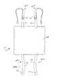
- FIG. 1is a perspective view, broken away in part, of a first embodiment of a cushion for use in seating for boats, the cushion being constructed according to the present invention
- FIG. 2is a top view of the cushion shown in FIG. 1 ;
- FIG. 3is a bottom view of the cushion shown in FIG. 1 ;
- FIG. 4is a right side view, broken away in part, of the cushion shown in FIG. 1 ;
- FIG. 5is a left side view of the cushion shown in FIG. 1 ;
- FIG. 6is a front view of the cushion shown in FIG. 1 ;
- FIG. 7is a rear view of the cushion shown in FIG. 1 ;
- FIG. 8is a right side view showing the cushion of FIG. 1 secured to a bucket-type boat seat
- FIGS. 9( a ) and 9( b )are top perspective and bottom perspective views, respectively, of a second embodiment of a cushion for use in seating for boats, the cushion being constructed according to the present invention
- FIG. 9( c )is a bottom perspective view of the cushion shown in FIG. 9( a ) , the cushion being shown with the casing partly opened to reveal the insert disposed therewithin;
- FIGS. 10( a ) through 10( c )are front, side and top views, respectively, of the insert shown in FIG. 9( c ) ;
- FIG. 11is a perspective view, broken away in part, of a third embodiment of a cushion for use in seating for boats, the cushion being constructed according to the present invention.
- FIG. 12is a top view of the cushion shown in FIG. 11 ;
- FIG. 13is a bottom view of the cushion shown in FIG. 11 ;
- FIG. 14is a right side view of the cushion shown in FIG. 11 ;
- FIG. 15is a left side view of the cushion shown in FIG. 11 ;
- FIG. 16is a front view of the cushion shown in FIG. 11 ;
- FIG. 17is a rear view of the cushion shown in FIG. 11 ;
- FIG. 18is a right side view showing the cushion of FIG. 11 secured to a pivotable bolster of a boat seat, the pivotal bolster being shown in a lowered position;
- FIG. 19is a right side view, broken away in part, showing the cushion of FIG. 11 secured to a pivotable bolster of a boat seat, the pivotal bolster being shown in a raised position;
- FIGS. 20( a ) and 20( b )are top perspective and bottom perspective views, respectively, of a fourth embodiment of a cushion for use in seating for boats, the cushion being constructed according to the present invention
- FIG. 20( c )is a bottom perspective view of the cushion shown in FIG. 20( a ) , the cushion being shown with the casing partly opened to reveal the insert disposed therewithin;
- FIGS. 21( a ) and 21( b )are top perspective and bottom perspective views, respectively, of the insert shown in FIG. 20( c ) ;
- FIG. 22is a side view showing the cushion of FIG. 20( a ) secured to a pivotable bolster of a boat seat (the boat seat not being shown).
- a purpose of the present inventionis to provide boat operators with a cushion that reduces the severity of contact between the body of an operator and an exposed portion of a boat seat while the boat is being operated, especially when the boat is planing.
- the cushionmakes it more tolerable for a boat operator to stand and to lean back against the boat seat when the boat is planing, thereby enabling the operator to have better visibility and permitting safer operation of the boat than would be the case if the operator remained seated.
- the cushion of the present inventionalso offers increased comfort to passengers who, like the boat operator, may be standing and leaning back against a seat.
- the cushion of the present inventionprovides increased comfort to both boat operators and passengers who remain seated, whether or not the boat is moving.
- certain embodiments of the present cushionare designed for attachment to the seat-portion of a bucket-type boating seat, and other embodiments of the present cushion are designed for attachment to a bolster of a bolster-type boating seat.
- cushion 11is specifically designed for attachment to the seat-portion of a bucket-type boating seat; however, it is to be understood that cushion 11 may have utility with other types of seats.
- Cushion 11may comprise an insert 13 , a casing 15 , a plurality of upper fastening mechanisms 17 - 1 and 17 - 2 , and a plurality of lower fastening mechanisms 19 - 1 and 19 - 2 .
- Insert 13comprises an impact damping material and may comprise, for example, a foam pad or a plurality of discrete foam pads. (Alternatively, insert 13 may comprise a material other than one or more foam pads.)
- the foam pad or plurality of discrete foam pads of insert 13each may comprise a unitary foam piece or may comprise a plurality of foam pieces of similar or dissimilar composition joined to one another by adhesive or other suitable means.
- insert 13exhibits the resilience and compressibility of a closed cell foam with a foam industry typical description ranging from 2-24 to 2-30. Lighter grades of foam may be used but are less preferred.
- Insert 13is preferably a generally J-shaped structure that comprises a top portion 21 , a bottom portion 23 , and a front portion 25 .
- top portion 21 , bottom portion 23 , and front portion 25may be constructed as three separate pieces that are joined to one another using, for example, an adhesive.
- Casing 15preferably conforms substantially to the shape of insert 13 and preferably covers the substantial entirety of insert 13 .
- Casing 15is preferably a generally flexible, thin-walled, protective material and may comprise any of a variety of different materials including, but not limited to, marine-grade vinyl using industry specifications of 22 ounce to 30 ounce material. Lesser quality vinyl could also be used but is less preferred in terms of resistance to wear and tear.
- SUINBRELLA® fabric, medium weight NYLON® polyamide, and any water-resistant polyvinyl chloride (PVC) materialmay also be used for the casing.
- Casing 15may be stitched with the stitching appearing on the inside seams and not visible on the outside.
- Casing 15may also be stitched on the outside seams using a decorative “bead” to hide the actual seams. It is also possible to “glue” the seams together, or tape the seams together, but the use of glue or tape does not offer the security or the finish quality that stitching offers. Every external surface of insert 13 is preferably covered by the casing material.
- insert 13 and casing 15may collectively define a top portion 22 having a length l 1 of approximately 19 inches to 22 inches, a width w 1 of approximately 14 inches to 16 inches, and a thickness t 1 of approximately 1 to 2 inches.
- insert 13 and casing 15may collectively define a bottom portion 24 having a length l 2 of approximately 8 inches to 12 inches, a width w 2 of approximately 14 to inches, and a thickness t 2 of approximately 2 inches to 3 inches.
- insert 13 and casing 15may collectively define a front portion 26 having a length l 3 of approximately 5 to 7 inches, a width w 3 of approximately 14 inches to 16 inches, and a thickness t 3 of approximately 1 to 2 inches.
- Upper fastening mechanisms 17 - 1 and 17 - 2may be secured by stitching or other suitable means to casing 15 proximate to the rear of top portion 21
- lower fastening mechanisms 19 - 1 and 19 - 2may be secured by stitching or other suitable means to casing 15 proximate to the rear of bottom portion 23
- upper fastening mechanisms 17 - 1 and 17 - 2each may comprise a flexible strap 31 having a snap element 33 proximate to the free end thereof
- lower fastening mechanisms 19 - 1 and 19 - 2each may comprise a flexible strap 35 having a snap element 37 proximate to the free end thereof.
- Snap elements 33 on upper fastening mechanisms 17 - 1 and 17 - 2are designed to mate with corresponding snap elements 39 on the rear bottom of a bucket-type seat 41 with which cushion 13 is used (see FIG. 8 ).
- snap elements 37 on lower fastening mechanisms 19 - 1 and 19 - 2are designed to mate with corresponding snap elements 43 on the front bottom of the bucket-type seat 41 with which cushion 13 is used (see FIG. 8 ).
- straps 31 and 35may have a length that is appropriate for the particular bucket-type seat 41 .
- straps 31 and 35may be constructed to be adjustable in length for use with differently dimensioned bucket-type seats 41 .
- insert 13may be produced as a unitary foam piece having a “J”-shape or may be assembled from a plurality of smaller foam pieces that are joined together by gluing or other suitable means. The foam piece or assembled foam pieces may be laid out and fit into a suitable casing material, and the casing material may then be stitched—either internally or externally—to form casing 15 with insert 13 disposed therewith. Finally, fastening mechanisms 17 - 1 , 17 - 2 , 19 - 1 and 19 - 2 may be attached to casing 15 .
- cushion 11is mounted onto the horizontal seating portion 45 of a bucket-type seat 41 and is secured in place using snap elements 39 and 43 .
- the top surface 45 - 1 of horizontal seating portion 45may be substantially covered by the top portion 22 of cushion 11
- the front surface 45 - 2 of horizontal seating portion 45may be substantially covered by the front portion 26 of cushion 11
- a portion of the bottom surface 45 - 3 of horizontal seating portion 45may be covered by the bottom portion 24 of cushion 11 .
- cushion 11must be appropriately dimensioned to receive the horizontal seating portion 45 of bucket-type seat 41 .
- top portion 22 and bottom portion 24must be appropriately spaced from one another to receive the horizontal seating portion 45 of bucket-type seat 41 .
- the spacing between top portion 22 and bottom portion 24is such that horizontal seating portion 45 is snugly received between top portion 22 and bottom portion 24 .
- hook/loop fasteners or other fastening mechanismssuch as quick release straps similar to those found on personal floatation devices, may be used instead of snap fasteners.
- Cushion 11can be used as a stand-alone cushion or can be used in addition to an existing or original boat seat cushion.
- the unique design of cushion 11offers increased protection to both operators and passengers who are seated in typical molded plastic or composite material seats by protecting their bodies from the exposed front edge of these typical boat seats. Further, cushion 11 offers protection from the vessel vibrations and body slamming that boaters face on every trip.
- FIGS. 9( a ) through 9( c )there are shown various views of a second embodiment of a cushion constructed according to the present invention, the cushion being represented generally by reference numeral 61 .
- Cushion 61is specifically designed for attachment to the seat-portion of a bucket-type boating seat; however, it is to be understood that cushion 61 may have utility with other types of seats.
- Cushion 61may be similar in many respects to cushion 11 . However, one difference between cushions 11 and 61 is that, whereas cushion 11 may comprise an insert 13 and a casing 15 , cushion 61 may comprise an insert 63 and a casing 65 .
- Insert 63which is also shown separately in FIGS. 10( a ) through 10( c ) , comprises an impact damping material and may be similar in many respects to insert 13 .
- insert 63may comprise a plurality of foam pads that are joined together.
- insert 63may comprise a top foam pad 67 - 1 , a bottom foam pad 67 - 2 , and an intermediate foam pad 67 - 3 .
- the top surface of intermediate foam pad 67 - 3may be joined to the bottom surface of top foam pad 67 - 1 by an adhesive (not shown) or other suitable means.
- intermediate foam pad 67 - 3may be joined to the top surface of bottom foam pad 67 - 2 by an adhesive (not shown) or other suitable means.
- top foam pad 67 - 1 and bottom foam pad 67 - 2may be positioned generally parallel to one another and may be spaced apart by intermediate foam pad 67 - 3 , whereby insert 63 may form a generally J-shaped structure.
- foam pads 67 - 1 through 67 - 3may be an open cell or closed cell polymer foam, such as a polyurethane foam or a polyether foam.
- An example of a suitable foam material for foam pads 67 - 1 through 67 - 3may be Crest Foam polyurethane foam, which is commercially available from Crest Foam Industries, Inc., Moonachie, N.J.
- Another example of a suitable foam materialmay be a polyether foam having a foam grade of 5250, which is available as Product Code B5250CHFR0 from Crest Foam Industries, Inc., Moonachie, N.J.
- top foam pad 67 - 1may have length l 4 of approximately 16 inches, a width w 4 of approximately 13 inches, and a thickness t 4 of approximately 21 ⁇ 4-21 ⁇ 2 inches.
- Bottom foam pad 67 - 2may have a length l 5 of approximately 5 inches, a width w 5 of approximately 13 inches, and a thickness t 5 of approximately 21 ⁇ 4 inches.
- Intermediate foam pad 67 - 3may have a length l 6 of approximately 21 ⁇ 4 inches, a width w 6 of approximately 13 inches, and a thickness t 6 of approximately 33 ⁇ 4 inches.
- Casing 65which may be similar in many respects to casing 15 , preferably conforms substantially to the shape of insert 63 and preferably covers the substantial entirety of insert 63 .
- Casing 65which may be made of a material that is similar to that used to make casing 15 , may comprise a plurality of pieces joined to one another. In the present embodiment, casing 65 may comprise five pieces 69 - 1 , 69 - 2 , 69 - 3 , 69 - 4 and 69 - 5 .
- Piece 69 - 1may be dimensioned to cover the top surface of top foam pad 67 - 1 , the front surfaces of top foam pad 67 - 1 , intermediate foam pad 67 - 3 , and bottom foam pad 67 - 2 , the bottom surface of bottom foam pad 67 - 2 , the rear surface of bottom foam pad 67 - 2 , the exposed portion of the top surface of bottom foam pad 67 - 2 , and a portion of the rear surface of intermediate foam pad 67 - 3 .
- Piece 69 - 2may be dimensioned to cover the right side surfaces of top foam pad 67 - 1 , intermediate foam pad 67 - 3 , and a bottom foam pad 67 - 2 , as well as covering a right half portion of the front of top foam pad 67 - 1 .
- Piece 69 - 3may be dimensioned to cover the left side surfaces of top foam pad 67 - 1 , intermediate foam pad 67 - 3 , and a bottom foam pad 67 - 2 , as well as covering a left half portion of the front of top foam pad 67 - 1 .
- Piece 69 - 4may be dimensioned to cover a right half portion of the bottom of top foam pad 67 - 1 , as well as a first portion of the rear surface of intermediate foam pad 67 - 3 .
- Piece 69 - 5may be dimensioned to cover a left half portion of the bottom of top foam pad 67 - 1 , as well as a second portion of the rear surface of intermediate foam pad 67 - 3 .
- Piece 69 - 1may be stitched to each of pieces 69 - 2 and 69 - 3 at their respective adjacent edges
- pieces 69 - 2 and 69 - 3may be stitched to one another at their respective adjacent edges
- pieces 69 - 2 and 69 - 4may be stitched to one another at their respective adjacent edges
- pieces 69 - 3 and 69 - 5may be stitched to one another at their respective adjacent edges.
- Pieces 69 - 4 and 69 - 5may be repeatedly joined to one another and then separated from one another at their respective adjacent edges by a zipper 71 , and each of pieces 69 - 4 and 69 - 5 may be repeatedly joined to and then separated from piece 69 - 1 at their respective adjacent edges by complementary strips of hook and loop fasteners.
- strips of hook fasteners 73may be detachably secured to the inner faces of each of pieces 69 - 4 and 69 - 5
- a strip of loop fasteners 75may be detachably secured to the outer face of piece 69 - 1 .
- the provision of zipper 71 , hook fasteners 73 and loop fasteners 75may facilitate the insertion of insert 63 into casing 65 and, if needed, the removal of insert 63 from casing 65 .
- cushions 61 and 11Yet another difference between cushions 61 and 11 is that, whereas cushion 11 comprises fastening mechanisms 17 - 1 , 17 - 2 , 19 - 1 and 19 - 2 , cushion 61 does not comprise fastening mechanisms 17 - 1 , 17 - 2 , 19 - 1 , 19 - 2 ; instead, cushion 61 may comprise one or more strips of hook/loop fasteners 81 secured to the bottom surface of the top portion of casing 15 , and one or more complementary strips of hook/loop fasteners may be secured to the top of the horizontal seating portion of the bucket-type seat.
- cushion 61may be used in a generally similar fashion as cushion 11 . If desired, cushion 61 may be dimensioned to snugly receive the horizontal seating portion of the bucket-type seat to which it is attached. Like cushion 11 , cushion 61 can be used as a stand-alone cushion or can be used in addition to an existing or original boat seat cushion.
- FIGS. 11 through 17there are shown various views of a third embodiment of a cushion constructed according to the teachings of the present invention, the cushion being represented generally by reference numeral 101 .
- Cushion 101which is designed to be attached to the bolster of a bolster-type boating seat, may comprise an insert 103 , a casing 105 , a plurality of rearward-facing fastening mechanisms 107 - 1 and 107 - 2 , and a plurality of forward-facing fastening mechanisms 109 - 1 and 109 - 2 .
- Insert 103comprises an impact damping material and may comprise, for example, a foam pad or a plurality of discrete foam pads. (Alternatively, insert 103 may comprise a material other than one or more foam pads.)
- the foam pad or plurality of discrete foam pads of insert 103each may comprise a unitary foam piece or may comprise a plurality of foam pieces of similar or dissimilar composition joined to one another by adhesive or other suitable means.
- insert 103exhibits the resilience and compressibility of a closed cell foam with a foam industry typical description ranging from 2-24 to 2-30, with 2-27 being particularly preferred. Lighter grades of foam may be used but are less preferred.
- Insert 103preferably has a generally rectangular prismatic shape.
- Casing 105preferably conforms substantially to the shape of insert 103 and preferably covers the substantial entirety of insert 103 .
- Casing 105may be a generally flexible, thin-walled, protective material and may comprise any of a variety of different materials including, but not limited to, marine-grade vinyl using industry specifications of 22 ounce to 30 ounce material. Lesser quality vinyl could also be used but is less preferred in terms of resistance to wear and tear.
- SUNBRELLA® fabric, medium weight NYLON® polyamide, and any water-resistant polyvinyl chloride (PVC) materialmay also be used for the casing. Large sheets of plastic or canvas may be cut and trimmed to fit around the insert as well.
- Casing 105may be stitched with the stitching appearing on the inside seams and not visible on the outside. Casing 105 may also be stitched on the outside seams using a decorative “bead” to hide the actual seams. It is also possible to “glue” the seams together, or tape the seams together, but the use of glue or tape does not offer the security or the finish quality that stitching offers. Every external surface of insert 103 is preferably covered by the casing material.
- insert 103 and casing 105may collectively have a generally rectangular prismatic shape and may have a length l 7 of approximately 16 inches, a width w 7 of approximately 16 inches, and a thickness t 7 of approximately 1.5 to 3 inches (which may vary depending on the type of foam used).
- Rearward-facing fastening mechanisms 107 - 1 and 107 - 2may be secured by stitching or other suitable means to the rear of casing 105
- forward-facing fastening mechanisms 109 - 1 and 109 - 2may be secured by stitching or other suitable means to the front of casing 105
- fastening mechanisms 107 - 1 and 107 - 2each may comprise a flexible strap 111 having a male element 113 of a quick release fastener proximate to the free end thereof
- fastening mechanisms 109 - 1 and 109 - 2each may comprise a flexible strap 115 having a female element 117 of a quick release fastener proximate to the free end thereof.
- Male elements 113 and female elements 117are designed to mate with one another in the conventional fashion. In this manner, cushion 101 may be secured to a bolster 121 (see FIGS. 18 and 19 ). Straps 111 and/or 115 may have a length that is adjustable for accommodating differently dimensioned bolsters.
- an insert as described aboveis first provided.
- a pivoting bolstertypically extends the full width of its corresponding seat, it is generally not necessary to protect the outer 2-3 inches of the bolster itself. The reason is that the seat occupant will typically sit in the center of the bolster, not to the extreme edges/ends.
- the pivoting bolstertypically has measurements, as viewed from an end of bolster, of either approximately 7 inches ⁇ 7 inches or approximately 8 inches ⁇ 8 inches.
- the foam insertis preferably cut to fit either measurement noted above.
- a covering materialas previously mentioned, is cut so that it has sufficient length and width to cover the foam insert and overlap the vertical (height) surfaces, approximately 2 inches. At this point, the covering material typically covers all sides of the foam insert, except for the bottom surface.
- the covering materialis cut to a sufficient dimension so that the bottom of the insert is covered but allowing enough extra fabric so that the upper and lower covering materials, the shell, can be stitched.
- the two quick release strapsare sewn/stitched securely, or otherwise attached, to the inner surface of the top side cover.
- the foam insertis placed onto the just stitched cover and strap and the bottom piece of the shell.
- the coveris then stitched to the top/upper cover.
- the foam insertis inserted into the casing that has just been crafted and then the final stitching is completed.
- the stitchingcan all be done on the interior of the casing so as to not be visible or the stitching may be done on the outside of the cushion and finished off with a decorative “bead” that will hide the stitching.
- cushion 101on bolster 121 can be seen. As seen best in FIG. 19 , when bolster 121 is moved to its “up” position, cushion 101 offers protection to the user from the encased plywood “frame” 123 of the bolster 121 , which is now positioned at the front of the bolster 121 .
- a side to side notchmay be provided in the underside of the foam, such a notch improving the fit of the cushion to the 90 degree turn at the corner of the bolster.
- FIGS. 20( a ) through 20( c )there are shown various views of a fourth embodiment of a cushion constructed according to the present invention, the cushion being represented generally by reference numeral 161 .
- Cushion 161is specifically designed for attachment to a bolster of a bolster-type boating seat; however, it is to be understood that cushion 161 may have utility with other types of seats.
- Cushion 161may be similar in many respects to cushion 101 . However, one difference between cushions 161 and 101 is that, whereas cushion 101 may comprise an insert 103 and a casing 105 , cushion 161 may comprise an insert 163 and a casing 165 .
- Insert 163which is also shown separately in FIGS. 21( a ) and 21( b ) , comprises an impact damping material.
- insert 163may comprise a one-piece foam pad, which may be an open cell or closed cell polymer foam, such as a polyurethane foam or a polyether foam.
- An example of a suitable foam material for insert 163may be Crest Foam polyurethane foam, which is commercially available from Crest Foam Industries, Inc., Moonachie, N.J.
- Another example of a suitable foam materialmay be a polyether foam having a foam grade of 5250, which is available as Product Code B5250CHFR0 from Crest Foam Industries, Inc., Moonachie, N.J.
- Insert 163which may have a generally trapezoidal prismatic shape, may include a top 167 , a bottom 169 , a front 171 , a rear 173 , a left side 175 , and a right side 177 .
- a plurality of notches 179 - 1 through 179 - 4which may be similarly shaped and dimensioned to one another and which are preferably V-shaped in transverse cross-section, may be provided along bottom 169 , notches 179 - 1 through 179 - 4 helping to permit insert 163 to be bent so that front 171 and rear 173 may be drawn towards one another.
- Notches 179 - 1 through 179 - 4may extend from left side 175 to right side 177 and may extend partially from bottom 169 towards top 167 . Although four notches 179 are shown in the present embodiment, it is to be understood that the number of notches 179 may be greater than four or less than four.
- top 167may have a length of approximately 18.5 inches
- bottom 169may have a length of approximately 20.75 inches
- the distance from left side 175 to right side 177may be approximately 16.25 inches
- the distance from top 167 to bottom 169may be approximately 2.25 inches
- notches 179 - 1 through 179 - 4each may have a depth of approximately 3 ⁇ 4 inch
- notches 179 - 1 through 179 - 4may be spaced apart from one another by approximately 3 inches
- the distance from front 171 to notch 179 - 1may be approximately 4.5 inches
- the distance from rear 173 to notch 179 - 4may be approximately 4.5 inches.
- Casing 165which may be similar in many respects to casing 105 , preferably conforms substantially to the shape of insert 163 and preferably covers the substantial entirety of insert 163 .
- Casing 165which may be made of a material that is similar to that used to make casing 105 , may comprise a plurality of pieces joined to one another.
- casing 165may comprise seven pieces 189 - 1 , 189 - 2 , 189 - 3 , 189 - 4 , 189 - 5 , 189 - 6 , and 189 - 7 .
- Piece 189 - 1may be dimensioned to cover the top 167 of insert 163 and may extend beyond front 171 of insert 163 to define a front flap portion 190 - 1 and also may extend beyond rear 173 of insert 163 to define a rear flap portion 190 - 2 .
- Piece 189 - 2may be dimensioned to cover the left side 175 of insert 163
- piece 189 - 3may be dimensioned to cover the right side 177 of insert 163 .
- Piece 189 - 4may be dimensioned to cover a left half portion of insert 163
- piece 189 - 5may be dimensioned to cover a right half portion of insert 163 .
- Piece 189 - 1may be stitched to each of pieces 189 - 2 and 189 - 3 at their respective adjacent edges.
- Piece 189 - 2may be stitched to piece 189 - 4 at their respective adjacent edges, and piece 189 - 3 may be stitched to piece 189 - 5 at their respective adjacent edges.
- Pieces 189 - 4 and 189 - 5may be repeatedly joined to one another and separated from one another at their respective adjacent edges by a zipper 191 .
- each of pieces 189 - 4 and 189 - 5may be stitched to piece 189 - 1 , and the opposite end of each of pieces 189 - 4 and 189 - 5 may be repeatedly joined to and separated from piece 189 - 1 at their respective adjacent edges by complementary strips of hook and loop fasteners.
- strips of hook fasteners 193may be detachably secured to the inner faces of each of pieces 189 - 4 and 189 - 5
- a strip of loop fasteners 195may be detachably secured to the outer bottom face of piece 189 - 1 .
- the provision of zipper 191 , hook fasteners 193 and loop fasteners 195may facilitate the insertion of insert 163 into casing 165 and, if needed, the removal of insert 163 from casing 165 .
- the pocket defined by casing 165may be slightly undersized in length relative to insert 163 so that insert 163 assumes an arcuate shape when disposed within casing 165 .
- Piece 189 - 6may be stitched to the bottom of front flap portion 190 - 1
- piece 189 - 7may be stitched to the bottom of front flap portion 190 - 2
- a strip of hook fasteners 197may be stitched or otherwise secured to the bottom of piece 189 - 6
- a strip of complementary loop fasteners 199may be stitched or otherwise secured to the top of rear flap portion 190 - 2 . As can be seen, for example, in FIG.
- casing 165may be appropriately dimensioned, and hook fasteners 197 and loop fasteners 199 may be appropriately positioned on casing 165 so that casing 165 may be wrapped around a bolster, and hook fasteners 197 and loop fasteners 199 may be secured to one another, thereby securing cushion 161 to the bolster.
- cushion 161thus secured to a bolster, if the bolster is moved to its “up” position, the wooden frame 123 that would then be positioned at the front of the bolster will be cushioned by cushion 161 .
Landscapes
- Chemical & Material Sciences (AREA)
- Engineering & Computer Science (AREA)
- Combustion & Propulsion (AREA)
- Mechanical Engineering (AREA)
- Ocean & Marine Engineering (AREA)
- Mattresses And Other Support Structures For Chairs And Beds (AREA)
Abstract
Description
Claims (8)
Priority Applications (3)
| Application Number | Priority Date | Filing Date | Title |
|---|---|---|---|
| US15/646,457US10414468B2 (en) | 2016-05-06 | 2017-07-11 | Cushions for use in seating for boats and methods of using said cushions |
| US29/627,592USD897729S1 (en) | 2017-07-11 | 2017-11-28 | Cushion for a boat seat bolster |
| US29/627,572USD845673S1 (en) | 2017-07-11 | 2017-11-28 | Boat seat cushion |
Applications Claiming Priority (4)
| Application Number | Priority Date | Filing Date | Title |
|---|---|---|---|
| US29/563,731USD823025S1 (en) | 2016-05-06 | 2016-05-06 | Boat seat cushion |
| US29563721 | 2016-05-06 | ||
| US201662360520P | 2016-07-11 | 2016-07-11 | |
| US15/646,457US10414468B2 (en) | 2016-05-06 | 2017-07-11 | Cushions for use in seating for boats and methods of using said cushions |
Related Parent Applications (2)
| Application Number | Title | Priority Date | Filing Date |
|---|---|---|---|
| US29/563,731Continuation-In-PartUSD823025S1 (en) | 2016-05-06 | 2016-05-06 | Boat seat cushion |
| US29563721Continuation-In-Part | 2016-05-06 | 2016-05-06 |
Related Child Applications (2)
| Application Number | Title | Priority Date | Filing Date |
|---|---|---|---|
| US29/627,592ContinuationUSD897729S1 (en) | 2017-07-11 | 2017-11-28 | Cushion for a boat seat bolster |
| US29/627,572Continuation-In-PartUSD845673S1 (en) | 2017-07-11 | 2017-11-28 | Boat seat cushion |
Publications (2)
| Publication Number | Publication Date |
|---|---|
| US20170320551A1 US20170320551A1 (en) | 2017-11-09 |
| US10414468B2true US10414468B2 (en) | 2019-09-17 |
Family
ID=60242901
Family Applications (1)
| Application Number | Title | Priority Date | Filing Date |
|---|---|---|---|
| US15/646,457Expired - Fee RelatedUS10414468B2 (en) | 2016-05-06 | 2017-07-11 | Cushions for use in seating for boats and methods of using said cushions |
Country Status (1)
| Country | Link |
|---|---|
| US (1) | US10414468B2 (en) |
Cited By (2)
| Publication number | Priority date | Publication date | Assignee | Title |
|---|---|---|---|---|
| USD897729S1 (en)* | 2017-07-11 | 2020-10-06 | Regal Boat Seat Cushions Inc. | Cushion for a boat seat bolster |
| USD950073S1 (en)* | 2019-12-24 | 2022-04-26 | Global Medical Foam, Inc. | Scrotal edema pressure redistribution device |
Families Citing this family (6)
| Publication number | Priority date | Publication date | Assignee | Title |
|---|---|---|---|---|
| USD823025S1 (en) | 2016-05-06 | 2018-07-17 | Regal Boat Seat Cushions Inc. | Boat seat cushion |
| USD845673S1 (en)* | 2017-07-11 | 2019-04-16 | Regal Boat Seat Cushions Inc. | Boat seat cushion |
| GB2576296A (en)* | 2018-06-25 | 2020-02-19 | A J Equestrian Ltd | Support device |
| US11623718B2 (en)* | 2021-07-13 | 2023-04-11 | Alfred Joseph Koontz, IV | Beanbag with storage |
| USD958554S1 (en)* | 2021-12-10 | 2022-07-26 | Scott Matheson | Hunting seat |
| US11974675B1 (en)* | 2023-11-09 | 2024-05-07 | Kemnitzer/Powell, LLC | Seating assembly |
Citations (84)
| Publication number | Priority date | Publication date | Assignee | Title |
|---|---|---|---|---|
| US2782840A (en) | 1955-04-20 | 1957-02-26 | Crawford Mfg Co Inc | Adjustable "t" cushion cover |
| US3046573A (en) | 1960-12-14 | 1962-07-31 | Sr Robert E Davis | Reversible automobile arm rest pillow |
| US3369262A (en) | 1966-09-27 | 1968-02-20 | Mc Donnell Douglas Corp | Flotation cushion |
| US3903554A (en) | 1973-12-19 | 1975-09-09 | Universal Oil Prod Co | Seating unit with removable life preserver section |
| US4190918A (en) | 1978-07-05 | 1980-03-04 | Harvell Glenn M | Combination folding cushion and carrying assembly |
| US4212496A (en)* | 1978-04-13 | 1980-07-15 | Kirkham Arthur J Jr | Cushion for ski lift chair |
| US4291916A (en) | 1978-11-13 | 1981-09-29 | Chardon Max M F | Seat for bus, train or airplane |
| GB2165623A (en) | 1983-03-16 | 1986-04-16 | Scandus Design Ltd | Seats |
| US4729599A (en)* | 1987-01-27 | 1988-03-08 | Gymnasium Protection Systems, Inc. | Bleacher cushions |
| US4789046A (en) | 1987-08-17 | 1988-12-06 | Pro Board, Inc. | Cement finisher's knee board |
| US4802249A (en) | 1988-02-19 | 1989-02-07 | Bills Earl C | Portable multiple section adjustable posture contour care bed |
| US4926783A (en) | 1988-07-08 | 1990-05-22 | Outboard Marine Corporation | Recreational boat seat/sun deck |
| USD315076S (en) | 1989-02-13 | 1991-03-05 | Hanna Cynthia L | Child's car pilllow |
| USD315993S (en) | 1987-08-13 | 1991-04-09 | Joseph Wenderoth | Auxiliary safety seat for use primarily in a high chair |
| US5029928A (en) | 1990-05-25 | 1991-07-09 | Huber John G | Pickup truck bed seat |
| US5070664A (en)* | 1989-04-18 | 1991-12-10 | Crane Plastics, Inc. | Thermoplastic cover for stadium seating, picnic tables, boat docks and the like |
| USD324769S (en) | 1989-04-25 | 1992-03-24 | Patricia Hart | Beach tote bag with head support |
| USD324970S (en) | 1989-07-31 | 1992-03-31 | Oprington Company, Ltd. | Combination collapsible baby bed and shoulder bag |
| USD328001S (en) | 1989-11-13 | 1992-07-21 | Kelly Basil T | Countertop |
| US5171063A (en) | 1991-05-29 | 1992-12-15 | Robert Stidd | Helm chair |
| USD336791S (en) | 1991-05-29 | 1993-06-29 | Robert Stidd | Helm chair |
| USD362579S (en) | 1994-09-26 | 1995-09-26 | Short Daniel W | Cushion with storage pockets |
| USD366383S (en) | 1994-11-25 | 1996-01-23 | Kenneth B. Briegleb | Folding attachable seat cushion |
| USD366800S (en) | 1994-07-21 | 1996-02-06 | Moore Jr Mark B | Combined stadium cushion and carrying bag |
| US5491851A (en) | 1994-02-01 | 1996-02-20 | Alonso; Frank | Child's multipurpose, multisectional mat with carrying handles |
| USD376701S (en) | 1995-12-01 | 1996-12-24 | Genmar Industries, Inc. | Rotational bolster seat |
| US5619949A (en) | 1995-09-06 | 1997-04-15 | Dick, Jr.; Edward F. | Multi-positional marine seat bolster |
| USD379047S (en) | 1996-01-29 | 1997-05-06 | Richard Stephanie E | Foldable bleacher seat with securement straps |
| USD381855S (en) | 1995-12-12 | 1997-08-05 | Galick Jennifer I | Pillow |
| USD382756S (en) | 1995-01-13 | 1997-08-26 | Sign of the Whale, L.L.C. | Tote-towel/beach bag |
| US5857423A (en) | 1995-12-26 | 1999-01-12 | Yamaha Hatsudoki Kabushiki Kaisha | Seat arrangement for a watercraft |
| US5921626A (en)* | 1997-12-23 | 1999-07-13 | Baker; Stephen A. | Bleacher seat cushion |
| US5950263A (en) | 1996-11-12 | 1999-09-14 | Sunrise Medical Hhg Inc. | Length extender for child's wheelchair seating system |
| US6042093A (en) | 1998-01-12 | 2000-03-28 | Garelick Mfg. Co. | Boat seat shock absorber |
| US6325456B1 (en) | 2000-02-18 | 2001-12-04 | Garnett Carnahan | Chair with a sliding and swiveling device |
| USD462862S1 (en)* | 2001-12-11 | 2002-09-17 | Perry Chemical & Manufacturing Co., Inc. | Stadium seat cushion |
| USD463701S1 (en) | 2001-10-19 | 2002-10-01 | Roho, Incorporated | Seat cushion |
| USD474934S1 (en) | 2001-07-30 | 2003-05-27 | Tom Ildstad | Carrying bag attachable to stadium seats |
| US6692076B1 (en)* | 2002-02-04 | 2004-02-17 | Peter J. Burer | Bolster chair with foldable seat that is vertically adjustable when folded into a vertical position |
| USD503867S1 (en) | 2003-08-01 | 2005-04-12 | Bennette Design Group, Inc. | Plumber's pad |
| US20050138733A1 (en) | 2003-12-30 | 2005-06-30 | Jody Riesberg | Side sleeping pillow |
| US20050177944A1 (en)* | 2002-03-16 | 2005-08-18 | Kang Tae G. | Pillow |
| US20060022499A1 (en)* | 2003-01-22 | 2006-02-02 | Troy Jones | Bleacher cushion |
| US20070001503A1 (en) | 2005-07-01 | 2007-01-04 | John Brady | Furniture accessory footrest |
| USD572069S1 (en) | 2008-03-25 | 2008-07-01 | Mcqueen Cliff | Automotive center console arm rest cover |
| US20080178789A1 (en)* | 2007-01-26 | 2008-07-31 | Roehm Marine, Llc | Marine seating system and apparatus |
| USD575536S1 (en) | 2007-12-05 | 2008-08-26 | Snuggle Nest, Llc | Bassinet |
| US20080315644A1 (en) | 2007-06-21 | 2008-12-25 | Betty Jane Briscoe | Accessory car seat cushion |
| US7523988B1 (en) | 2003-08-25 | 2009-04-28 | Milsco Manufacturing Company, A Unit Of Jason Incorporated | Seat, suspension, bolster and shell |
| USD602298S1 (en) | 2007-02-12 | 2009-10-20 | Johann Zwanzgleitner | Cushion with display |
| US20100037814A1 (en) | 2008-04-17 | 2010-02-18 | Ronald Clifford Sahr | Sundeck with Self-Stowing Rumble Seat for a Boat |
| JP2010221861A (en) | 2009-03-24 | 2010-10-07 | Koito Ind Ltd | Seat device |
| USD635265S1 (en) | 2010-03-02 | 2011-03-29 | Melissa Coffey | Support cushion for sexual positioning |
| USD634951S1 (en) | 2004-03-04 | 2011-03-29 | Cushion Seats, Inc. | Stadium seat |
| US20120256466A1 (en) | 2011-04-01 | 2012-10-11 | Recticel Holding Noord B.V. | Seat cushion, for instance for an aircraft seat, and a method for manufacturing such a seat cushion |
| US8336965B2 (en) | 2006-12-22 | 2012-12-25 | The Boeing Company | Composite seat pan structure for a lightweight aircraft seat assembly |
| USD677506S1 (en) | 2011-10-28 | 2013-03-12 | Innovations for Living Ltd. | Pillow |
| US20130263377A1 (en)* | 2012-04-04 | 2013-10-10 | Homtex, Inc. | Customizable Pillow and Mattress |
| GB2502508A (en) | 2012-03-27 | 2013-12-04 | Design Que Ltd | Aircraft passenger seat |
| USD695548S1 (en) | 2012-09-06 | 2013-12-17 | Coretta Johnson | Pillow |
| USD696532S1 (en) | 2012-04-05 | 2013-12-31 | Charlène von Saher | Cushion |
| US8695136B2 (en) | 2012-02-24 | 2014-04-15 | Be Aerospace, Inc. | Seat cushion with distributed flotation foam use in aircraft seats |
| US8702120B2 (en) | 2012-06-27 | 2014-04-22 | Ford Global Technologies, Llc | Active bolster deployed from vehicle seat |
| USD702979S1 (en) | 2012-01-09 | 2014-04-22 | J Squared, Inc. | Stool seat |
| US20140117738A1 (en)* | 2012-10-31 | 2014-05-01 | Tenryu Industries Co., Ltd. | Vehicle seat |
| US8782835B2 (en) | 2012-03-20 | 2014-07-22 | Be Aerospace, Inc. | Seat cushion with integrated seat frame attachment structure |
| USD713664S1 (en) | 2013-02-07 | 2014-09-23 | Mayline Company Llc | Chair with back support and seat |
| US8910330B1 (en) | 2013-05-14 | 2014-12-16 | Ez Cuddle, Llc | Cuddling pillow |
| USD725923S1 (en) | 2013-10-24 | 2015-04-07 | Mel Kaye | Edge mount foot rest |
| USD725924S1 (en) | 2013-10-24 | 2015-04-07 | Mel Kaye | Edge mount foot rest |
| USD725925S1 (en) | 2013-10-24 | 2015-04-07 | Mel Kaye | Corner mount foot rest |
| US9045197B2 (en) | 2013-02-07 | 2015-06-02 | Kate Chen | Boat seat base assembly |
| US20150158560A1 (en)* | 2013-12-06 | 2015-06-11 | Richard Velasquez | Bolster cushion and methods of use |
| USD737073S1 (en) | 2013-09-30 | 2015-08-25 | The Sleep Company | Modular pillow system |
| USD740043S1 (en) | 2014-08-31 | 2015-10-06 | Zinus, Inc. | Molded foam sofa middle section |
| US20150359353A1 (en)* | 2012-11-08 | 2015-12-17 | Red Star Traders, Llc | Cushion Covers, Cushions, and Methods of Using the Same |
| USD747117S1 (en) | 2013-05-07 | 2016-01-12 | Ideal Time Consultants Limited | Airbed |
| USD749873S1 (en) | 2014-06-04 | 2016-02-23 | Pasquale Latrofa | Hunting pillow |
| US20160192794A1 (en) | 2015-01-07 | 2016-07-07 | Dennis M. Boyd | Pillow |
| US20160296031A1 (en) | 2014-01-27 | 2016-10-13 | Level Sleep Llc | Support pillows and mattresses for body alignment |
| USD769028S1 (en) | 2015-03-03 | 2016-10-18 | Claire Little | Back support |
| US20160338514A1 (en) | 2015-05-21 | 2016-11-24 | King Chan | Foam pillows |
| USD775484S1 (en) | 2014-12-15 | 2017-01-03 | James Moore | Pillow |
| USD790235S1 (en) | 2016-03-29 | 2017-06-27 | Khai Gan Chuah | Baby carrier seat insert |
Family Cites Families (2)
| Publication number | Priority date | Publication date | Assignee | Title |
|---|---|---|---|---|
| ITRM20020500A1 (en)* | 2002-10-04 | 2004-04-05 | Micron Technology Inc | ULTRA-LOW CURRENT BAND-GAP VOLTAGE REFERENCE. |
| SE535252C2 (en)* | 2010-04-08 | 2012-06-05 | Lars Svensson | Molding kit for casting building models |
- 2017
- 2017-07-11USUS15/646,457patent/US10414468B2/ennot_activeExpired - Fee Related
Patent Citations (84)
| Publication number | Priority date | Publication date | Assignee | Title |
|---|---|---|---|---|
| US2782840A (en) | 1955-04-20 | 1957-02-26 | Crawford Mfg Co Inc | Adjustable "t" cushion cover |
| US3046573A (en) | 1960-12-14 | 1962-07-31 | Sr Robert E Davis | Reversible automobile arm rest pillow |
| US3369262A (en) | 1966-09-27 | 1968-02-20 | Mc Donnell Douglas Corp | Flotation cushion |
| US3903554A (en) | 1973-12-19 | 1975-09-09 | Universal Oil Prod Co | Seating unit with removable life preserver section |
| US4212496A (en)* | 1978-04-13 | 1980-07-15 | Kirkham Arthur J Jr | Cushion for ski lift chair |
| US4190918A (en) | 1978-07-05 | 1980-03-04 | Harvell Glenn M | Combination folding cushion and carrying assembly |
| US4291916A (en) | 1978-11-13 | 1981-09-29 | Chardon Max M F | Seat for bus, train or airplane |
| GB2165623A (en) | 1983-03-16 | 1986-04-16 | Scandus Design Ltd | Seats |
| US4729599A (en)* | 1987-01-27 | 1988-03-08 | Gymnasium Protection Systems, Inc. | Bleacher cushions |
| USD315993S (en) | 1987-08-13 | 1991-04-09 | Joseph Wenderoth | Auxiliary safety seat for use primarily in a high chair |
| US4789046A (en) | 1987-08-17 | 1988-12-06 | Pro Board, Inc. | Cement finisher's knee board |
| US4802249A (en) | 1988-02-19 | 1989-02-07 | Bills Earl C | Portable multiple section adjustable posture contour care bed |
| US4926783A (en) | 1988-07-08 | 1990-05-22 | Outboard Marine Corporation | Recreational boat seat/sun deck |
| USD315076S (en) | 1989-02-13 | 1991-03-05 | Hanna Cynthia L | Child's car pilllow |
| US5070664A (en)* | 1989-04-18 | 1991-12-10 | Crane Plastics, Inc. | Thermoplastic cover for stadium seating, picnic tables, boat docks and the like |
| USD324769S (en) | 1989-04-25 | 1992-03-24 | Patricia Hart | Beach tote bag with head support |
| USD324970S (en) | 1989-07-31 | 1992-03-31 | Oprington Company, Ltd. | Combination collapsible baby bed and shoulder bag |
| USD328001S (en) | 1989-11-13 | 1992-07-21 | Kelly Basil T | Countertop |
| US5029928A (en) | 1990-05-25 | 1991-07-09 | Huber John G | Pickup truck bed seat |
| USD336791S (en) | 1991-05-29 | 1993-06-29 | Robert Stidd | Helm chair |
| US5171063A (en) | 1991-05-29 | 1992-12-15 | Robert Stidd | Helm chair |
| US5491851A (en) | 1994-02-01 | 1996-02-20 | Alonso; Frank | Child's multipurpose, multisectional mat with carrying handles |
| USD366800S (en) | 1994-07-21 | 1996-02-06 | Moore Jr Mark B | Combined stadium cushion and carrying bag |
| USD362579S (en) | 1994-09-26 | 1995-09-26 | Short Daniel W | Cushion with storage pockets |
| USD366383S (en) | 1994-11-25 | 1996-01-23 | Kenneth B. Briegleb | Folding attachable seat cushion |
| USD382756S (en) | 1995-01-13 | 1997-08-26 | Sign of the Whale, L.L.C. | Tote-towel/beach bag |
| US5619949A (en) | 1995-09-06 | 1997-04-15 | Dick, Jr.; Edward F. | Multi-positional marine seat bolster |
| USD376701S (en) | 1995-12-01 | 1996-12-24 | Genmar Industries, Inc. | Rotational bolster seat |
| USD381855S (en) | 1995-12-12 | 1997-08-05 | Galick Jennifer I | Pillow |
| US5857423A (en) | 1995-12-26 | 1999-01-12 | Yamaha Hatsudoki Kabushiki Kaisha | Seat arrangement for a watercraft |
| USD379047S (en) | 1996-01-29 | 1997-05-06 | Richard Stephanie E | Foldable bleacher seat with securement straps |
| US5950263A (en) | 1996-11-12 | 1999-09-14 | Sunrise Medical Hhg Inc. | Length extender for child's wheelchair seating system |
| US5921626A (en)* | 1997-12-23 | 1999-07-13 | Baker; Stephen A. | Bleacher seat cushion |
| US6042093A (en) | 1998-01-12 | 2000-03-28 | Garelick Mfg. Co. | Boat seat shock absorber |
| US6325456B1 (en) | 2000-02-18 | 2001-12-04 | Garnett Carnahan | Chair with a sliding and swiveling device |
| USD474934S1 (en) | 2001-07-30 | 2003-05-27 | Tom Ildstad | Carrying bag attachable to stadium seats |
| USD463701S1 (en) | 2001-10-19 | 2002-10-01 | Roho, Incorporated | Seat cushion |
| USD462862S1 (en)* | 2001-12-11 | 2002-09-17 | Perry Chemical & Manufacturing Co., Inc. | Stadium seat cushion |
| US6692076B1 (en)* | 2002-02-04 | 2004-02-17 | Peter J. Burer | Bolster chair with foldable seat that is vertically adjustable when folded into a vertical position |
| US20050177944A1 (en)* | 2002-03-16 | 2005-08-18 | Kang Tae G. | Pillow |
| US20060022499A1 (en)* | 2003-01-22 | 2006-02-02 | Troy Jones | Bleacher cushion |
| USD503867S1 (en) | 2003-08-01 | 2005-04-12 | Bennette Design Group, Inc. | Plumber's pad |
| US7523988B1 (en) | 2003-08-25 | 2009-04-28 | Milsco Manufacturing Company, A Unit Of Jason Incorporated | Seat, suspension, bolster and shell |
| US20050138733A1 (en) | 2003-12-30 | 2005-06-30 | Jody Riesberg | Side sleeping pillow |
| USD634951S1 (en) | 2004-03-04 | 2011-03-29 | Cushion Seats, Inc. | Stadium seat |
| US20070001503A1 (en) | 2005-07-01 | 2007-01-04 | John Brady | Furniture accessory footrest |
| US8336965B2 (en) | 2006-12-22 | 2012-12-25 | The Boeing Company | Composite seat pan structure for a lightweight aircraft seat assembly |
| US20080178789A1 (en)* | 2007-01-26 | 2008-07-31 | Roehm Marine, Llc | Marine seating system and apparatus |
| USD602298S1 (en) | 2007-02-12 | 2009-10-20 | Johann Zwanzgleitner | Cushion with display |
| US20080315644A1 (en) | 2007-06-21 | 2008-12-25 | Betty Jane Briscoe | Accessory car seat cushion |
| USD575536S1 (en) | 2007-12-05 | 2008-08-26 | Snuggle Nest, Llc | Bassinet |
| USD572069S1 (en) | 2008-03-25 | 2008-07-01 | Mcqueen Cliff | Automotive center console arm rest cover |
| US20100037814A1 (en) | 2008-04-17 | 2010-02-18 | Ronald Clifford Sahr | Sundeck with Self-Stowing Rumble Seat for a Boat |
| JP2010221861A (en) | 2009-03-24 | 2010-10-07 | Koito Ind Ltd | Seat device |
| USD635265S1 (en) | 2010-03-02 | 2011-03-29 | Melissa Coffey | Support cushion for sexual positioning |
| US20120256466A1 (en) | 2011-04-01 | 2012-10-11 | Recticel Holding Noord B.V. | Seat cushion, for instance for an aircraft seat, and a method for manufacturing such a seat cushion |
| USD677506S1 (en) | 2011-10-28 | 2013-03-12 | Innovations for Living Ltd. | Pillow |
| USD702979S1 (en) | 2012-01-09 | 2014-04-22 | J Squared, Inc. | Stool seat |
| US8695136B2 (en) | 2012-02-24 | 2014-04-15 | Be Aerospace, Inc. | Seat cushion with distributed flotation foam use in aircraft seats |
| US8782835B2 (en) | 2012-03-20 | 2014-07-22 | Be Aerospace, Inc. | Seat cushion with integrated seat frame attachment structure |
| GB2502508A (en) | 2012-03-27 | 2013-12-04 | Design Que Ltd | Aircraft passenger seat |
| US20130263377A1 (en)* | 2012-04-04 | 2013-10-10 | Homtex, Inc. | Customizable Pillow and Mattress |
| USD696532S1 (en) | 2012-04-05 | 2013-12-31 | Charlène von Saher | Cushion |
| US8702120B2 (en) | 2012-06-27 | 2014-04-22 | Ford Global Technologies, Llc | Active bolster deployed from vehicle seat |
| USD695548S1 (en) | 2012-09-06 | 2013-12-17 | Coretta Johnson | Pillow |
| US20140117738A1 (en)* | 2012-10-31 | 2014-05-01 | Tenryu Industries Co., Ltd. | Vehicle seat |
| US20150359353A1 (en)* | 2012-11-08 | 2015-12-17 | Red Star Traders, Llc | Cushion Covers, Cushions, and Methods of Using the Same |
| US9045197B2 (en) | 2013-02-07 | 2015-06-02 | Kate Chen | Boat seat base assembly |
| USD713664S1 (en) | 2013-02-07 | 2014-09-23 | Mayline Company Llc | Chair with back support and seat |
| USD747117S1 (en) | 2013-05-07 | 2016-01-12 | Ideal Time Consultants Limited | Airbed |
| US8910330B1 (en) | 2013-05-14 | 2014-12-16 | Ez Cuddle, Llc | Cuddling pillow |
| USD737073S1 (en) | 2013-09-30 | 2015-08-25 | The Sleep Company | Modular pillow system |
| USD725924S1 (en) | 2013-10-24 | 2015-04-07 | Mel Kaye | Edge mount foot rest |
| USD725925S1 (en) | 2013-10-24 | 2015-04-07 | Mel Kaye | Corner mount foot rest |
| USD725923S1 (en) | 2013-10-24 | 2015-04-07 | Mel Kaye | Edge mount foot rest |
| US20150158560A1 (en)* | 2013-12-06 | 2015-06-11 | Richard Velasquez | Bolster cushion and methods of use |
| US20160296031A1 (en) | 2014-01-27 | 2016-10-13 | Level Sleep Llc | Support pillows and mattresses for body alignment |
| USD749873S1 (en) | 2014-06-04 | 2016-02-23 | Pasquale Latrofa | Hunting pillow |
| USD740043S1 (en) | 2014-08-31 | 2015-10-06 | Zinus, Inc. | Molded foam sofa middle section |
| USD775484S1 (en) | 2014-12-15 | 2017-01-03 | James Moore | Pillow |
| US20160192794A1 (en) | 2015-01-07 | 2016-07-07 | Dennis M. Boyd | Pillow |
| USD769028S1 (en) | 2015-03-03 | 2016-10-18 | Claire Little | Back support |
| US20160338514A1 (en) | 2015-05-21 | 2016-11-24 | King Chan | Foam pillows |
| USD790235S1 (en) | 2016-03-29 | 2017-06-27 | Khai Gan Chuah | Baby carrier seat insert |
Non-Patent Citations (14)
| Title |
|---|
| "Deluxe Off White/Charcoal Vinyl Boat Bolster/Bucket/Drivers Seating Seat Chairs (Pair)," Great Lakes Skipper™, greatlakesskipper.com, GLS Stock #: 1045989, Part #: M2540BB00307, Jan. 15, 2016 http://greatlakesskipper.com/deluxe-off-white-charcoal-vinyl-boat-bolster-bucket-drivers-seating-seat-chairs-pair. |
| "Ladder Back Pilot Chair 1095 with Cushions, 15″ Fixed Pedestal and Seat Slide—Wise Boat Seats," iboats™, iboats.com, Part # WD1095-710, Jan. 15, 2016. http://www.iboats.com/Ladder-Back-Pilot-Chair-1095-with-Cushions-15-Fixed-Pedestal-and-Seat-Slide-Wise-Boat-Seats/dm/cart_id.464238942--session_id.419910167--view_id.375626. |
| "Wise Deluxe Pontoon," Restore Pontoon, restorepontoon.com, SKU: WD125-CO-xxxx, accessed: Jan. 15, 2016. http://www.restorepontoon.com/pontoon/pc/viewPrd.asp?idproduct=3042. |
| Jim Buoy Flotation Cushion, available at least on Aug. 27, 2013, [online], [site visited Aug. 2, 2017]. Available from Internet, <URL:http://www.defender.com/category.jsp?path=-1%7C135%7C2290066&id=2290114>. |
| Millennium ComfortMax SW-200 Saltwater Casting Boat Seat, accessed Dec. 22, 2017, http://www.millenniummarine.com/sw-series/sw-200/sw-200-white/. |
| Millennium ComfortMax SW-200 Saltwater Casting Boat Seat, accessed Oct. 2, 2017, http://www.basspro.com/shop/en/millennium-comfortmax-sw-200-sallwater-casting-boat-seat. |
| Safety Data Sheet Polyurethane Foam, Crest Foam Industries, Inc., Moonachie, New Jersey (Mar. 2016). |
| Tempress Guide Series Casting Seat, accessed Dec. 22, 2017, https://tempress.com/store/TEMPRESS-Guide-Series-Casting-Seat-Blue-Gray-p36736269. |
| Tempress Guide Series Casting Seat, accessed Oct. 2, 2017, http://www.basspro.com/shop/en/tempress-guide-series-casting-seat. |
| U.S. Appl. No. 29/563,721, inventor Martin J. Dennehy, filed May 6, 2016. |
| U.S. Appl. No. 29/563,731, inventor Martin J. Dennehy, filed May 6, 2016. |
| U.S. Appl. No. 29/627,572, inventor Martin J. Dennehy, filed Nov. 28, 2017. |
| U.S. Appl. No. 29/627,592, inventor Martin J. Dennehy, filed Nov. 28, 2017. |
| U.S. Appl. No. 29/630,607, inventor Martin J. Dennehy, filed Dec. 21, 2017. |
Cited By (2)
| Publication number | Priority date | Publication date | Assignee | Title |
|---|---|---|---|---|
| USD897729S1 (en)* | 2017-07-11 | 2020-10-06 | Regal Boat Seat Cushions Inc. | Cushion for a boat seat bolster |
| USD950073S1 (en)* | 2019-12-24 | 2022-04-26 | Global Medical Foam, Inc. | Scrotal edema pressure redistribution device |
Also Published As
| Publication number | Publication date |
|---|---|
| US20170320551A1 (en) | 2017-11-09 |
Similar Documents
| Publication | Publication Date | Title |
|---|---|---|
| US10414468B2 (en) | Cushions for use in seating for boats and methods of using said cushions | |
| US8733833B2 (en) | Safety or booster seat for use in conjunction with a vehicle | |
| US6223678B1 (en) | Inflatable kayak | |
| US5441331A (en) | Seating assembly | |
| US10791844B2 (en) | Collapsible flotation device | |
| US6929325B1 (en) | Portable ergonomic cushion | |
| US9332850B2 (en) | Reversible orthopedic seat cushion | |
| US7465207B2 (en) | Wearable personal floatation boating cushion apparatus | |
| US20120017821A1 (en) | Convertible seat for watercraft | |
| US20060226192A1 (en) | Backpack | |
| CA2147049A1 (en) | Seat | |
| JPS60259535A (en) | Children's booster chair | |
| US20200017219A1 (en) | Inflatable aisle-spanning double bed | |
| US20170196361A1 (en) | Back support cushion | |
| AU2003201842A1 (en) | Portable travel pillow | |
| ES2899282T3 (en) | Covering cover for motor vehicle seat base or backrest pad | |
| US3903554A (en) | Seating unit with removable life preserver section | |
| US20020069464A1 (en) | Saddle seat supplement and pad | |
| US20040074937A1 (en) | Combination backpack and child seat for a vehicle | |
| US20150158560A1 (en) | Bolster cushion and methods of use | |
| WO1994005189A2 (en) | Inflatable infant vehicle seat/bed | |
| CN210681055U (en) | Inflatable canoe | |
| US4961397A (en) | Challenge craft | |
| US20090064917A1 (en) | Kayak and Canoe seat | |
| WO2009102319A1 (en) | Backpack with cushioning means |
Legal Events
| Date | Code | Title | Description |
|---|---|---|---|
| AS | Assignment | Owner name:REGAL BOAT SEAT CUSHIONS INC., MASSACHUSETTS Free format text:ASSIGNMENT OF ASSIGNORS INTEREST;ASSIGNOR:DENNEHY, MARTIN J.;REEL/FRAME:044076/0175 Effective date:20171103 | |
| STPP | Information on status: patent application and granting procedure in general | Free format text:FINAL REJECTION MAILED | |
| STPP | Information on status: patent application and granting procedure in general | Free format text:RESPONSE AFTER FINAL ACTION FORWARDED TO EXAMINER | |
| STPP | Information on status: patent application and granting procedure in general | Free format text:NOTICE OF ALLOWANCE MAILED -- APPLICATION RECEIVED IN OFFICE OF PUBLICATIONS | |
| STPP | Information on status: patent application and granting procedure in general | Free format text:PUBLICATIONS -- ISSUE FEE PAYMENT RECEIVED | |
| STPP | Information on status: patent application and granting procedure in general | Free format text:PUBLICATIONS -- ISSUE FEE PAYMENT VERIFIED | |
| STCF | Information on status: patent grant | Free format text:PATENTED CASE | |
| AS | Assignment | Owner name:REGAL BOAT SEAT CUSHIONS INC., MASSACHUSETTS Free format text:CHANGE OF ADDRESS OF ASSIGNEE;ASSIGNOR:REGAL BOAT SEAT CUSHIONS INC.;REEL/FRAME:052565/0629 Effective date:20200504 | |
| AS | Assignment | Owner name:DENNEHY, MARTIN J., MASSACHUSETTS Free format text:ASSIGNMENT OF ASSIGNORS INTEREST;ASSIGNOR:REGAL BOAT SEAT CUSHIONS INC.;REEL/FRAME:058180/0809 Effective date:20211117 | |
| FEPP | Fee payment procedure | Free format text:MAINTENANCE FEE REMINDER MAILED (ORIGINAL EVENT CODE: REM.); ENTITY STATUS OF PATENT OWNER: SMALL ENTITY | |
| LAPS | Lapse for failure to pay maintenance fees | Free format text:PATENT EXPIRED FOR FAILURE TO PAY MAINTENANCE FEES (ORIGINAL EVENT CODE: EXP.); ENTITY STATUS OF PATENT OWNER: SMALL ENTITY | |
| STCH | Information on status: patent discontinuation | Free format text:PATENT EXPIRED DUE TO NONPAYMENT OF MAINTENANCE FEES UNDER 37 CFR 1.362 | |
| FP | Lapsed due to failure to pay maintenance fee | Effective date:20230917 |