US10414058B2 - Handle for a razor - Google Patents
Handle for a razorDownload PDFInfo
- Publication number
- US10414058B2 US10414058B2US15/234,998US201615234998AUS10414058B2US 10414058 B2US10414058 B2US 10414058B2US 201615234998 AUS201615234998 AUS 201615234998AUS 10414058 B2US10414058 B2US 10414058B2
- Authority
- US
- United States
- Prior art keywords
- projections
- handle
- projection
- height
- imaginary plane
- Prior art date
- Legal status (The legal status is an assumption and is not a legal conclusion. Google has not performed a legal analysis and makes no representation as to the accuracy of the status listed.)
- Active, expires
Links
- 239000000463materialSubstances0.000claimsabstractdescription25
- 229920002725thermoplastic elastomerPolymers0.000claimsdescription7
- 229910000831SteelInorganic materials0.000claimsdescription3
- 229910052782aluminiumInorganic materials0.000claimsdescription3
- XAGFODPZIPBFFR-UHFFFAOYSA-NaluminiumChemical compound[Al]XAGFODPZIPBFFR-UHFFFAOYSA-N0.000claimsdescription3
- 229910001220stainless steelInorganic materials0.000claimsdescription3
- 239000010935stainless steelSubstances0.000claimsdescription3
- 239000010959steelSubstances0.000claimsdescription3
- 230000008878couplingEffects0.000description7
- 238000010168coupling processMethods0.000description7
- 238000005859coupling reactionMethods0.000description7
- 238000000034methodMethods0.000description4
- 238000003032molecular dockingMethods0.000description3
- 238000012986modificationMethods0.000description2
- 230000004048modificationEffects0.000description2
- 229920000122acrylonitrile butadiene styrenePolymers0.000description1
- 239000004676acrylonitrile butadiene styreneSubstances0.000description1
- 230000002411adverseEffects0.000description1
- 239000011248coating agentSubstances0.000description1
- 238000000576coating methodMethods0.000description1
- 238000010276constructionMethods0.000description1
- 238000010586diagramMethods0.000description1
- 230000000694effectsEffects0.000description1
- -1for exampleSubstances0.000description1
- 230000004927fusionEffects0.000description1
- 238000009434installationMethods0.000description1
- 230000003993interactionEffects0.000description1
- 230000014759maintenance of locationEffects0.000description1
- 238000004519manufacturing processMethods0.000description1
- 229910052751metalInorganic materials0.000description1
- 239000002184metalSubstances0.000description1
- 238000003825pressingMethods0.000description1
- 238000000926separation methodMethods0.000description1
- 229920001935styrene-ethylene-butadiene-styrenePolymers0.000description1
- 229920001169thermoplasticPolymers0.000description1
- 239000004416thermosoftening plasticSubstances0.000description1
- XLYOFNOQVPJJNP-UHFFFAOYSA-NwaterSubstancesOXLYOFNOQVPJJNP-UHFFFAOYSA-N0.000description1
Images


Classifications
- B—PERFORMING OPERATIONS; TRANSPORTING
- B26—HAND CUTTING TOOLS; CUTTING; SEVERING
- B26B—HAND-HELD CUTTING TOOLS NOT OTHERWISE PROVIDED FOR
- B26B21/00—Razors of the open or knife type; Safety razors or other shaving implements of the planing type; Hair-trimming devices involving a razor-blade; Equipment therefor
- B26B21/40—Details or accessories
- B26B21/52—Handles, e.g. tiltable, flexible
- B26B21/521—Connection details, e.g. connection to razor heads
- B—PERFORMING OPERATIONS; TRANSPORTING
- B26—HAND CUTTING TOOLS; CUTTING; SEVERING
- B26B—HAND-HELD CUTTING TOOLS NOT OTHERWISE PROVIDED FOR
- B26B21/00—Razors of the open or knife type; Safety razors or other shaving implements of the planing type; Hair-trimming devices involving a razor-blade; Equipment therefor
- B26B21/08—Razors of the open or knife type; Safety razors or other shaving implements of the planing type; Hair-trimming devices involving a razor-blade; Equipment therefor involving changeable blades
- B26B21/14—Safety razors with one or more blades arranged transversely to the handle
- B26B21/22—Safety razors with one or more blades arranged transversely to the handle involving several blades to be used simultaneously
- B—PERFORMING OPERATIONS; TRANSPORTING
- B26—HAND CUTTING TOOLS; CUTTING; SEVERING
- B26B—HAND-HELD CUTTING TOOLS NOT OTHERWISE PROVIDED FOR
- B26B21/00—Razors of the open or knife type; Safety razors or other shaving implements of the planing type; Hair-trimming devices involving a razor-blade; Equipment therefor
- B26B21/40—Details or accessories
- B26B21/52—Handles, e.g. tiltable, flexible
- B26B21/522—Ergonomic details, e.g. shape, ribs or rubber parts
- B—PERFORMING OPERATIONS; TRANSPORTING
- B26—HAND CUTTING TOOLS; CUTTING; SEVERING
- B26B—HAND-HELD CUTTING TOOLS NOT OTHERWISE PROVIDED FOR
- B26B21/00—Razors of the open or knife type; Safety razors or other shaving implements of the planing type; Hair-trimming devices involving a razor-blade; Equipment therefor
- B26B21/40—Details or accessories
- B26B21/52—Handles, e.g. tiltable, flexible
- B26B21/528—Manufacture of razor handles
Definitions
- the systems described belowgenerally relate to a handle for a razor.
- Razor handlesare provided for attachment to a razor cartridge.
- a handle for a razor cartridgecomprises a head, a body, and a cover layer.
- the headhas a cartridge engaging end and an attachment end.
- the bodyis formed of a first material and defines a centerline.
- the bodyhas a front end and a rear end. The front end is coupled with the attachment end.
- the cover layerat least partially overlies the body and is formed of a second material.
- the cover layercomprises a base surface having a plurality of projections extending therefrom. Each projection of the plurality of projections has an upper surface that is substantially planar.
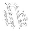
- FIG. 1is an isometric view depicting a handle for a razor cartridge
- FIG. 2is an exploded isometric view depicting the handle of FIG. 1 ;
- FIG. 3is an isometric view depicting the handle of FIG. 1 with certain components removed and other components shown in exploded view for clarity of illustration;
- FIG. 4is a side view depicting a right shell of the handle of FIG. 1 ;
- FIG. 5is a side view depicting a left shell of the handle of FIG. 1 ;
- FIG. 6is an isometric view depicting a head of the handle of FIG. 1 ;
- FIG. 7is a bottom view of the head of FIG. 6 ;
- FIG. 8is a side view of the head of FIG. 6 ;
- FIG. 9is an isometric exploded view depicting a clip member of the handle of FIG. 1 ;
- FIG. 10is a side view depicting the handle of FIG. 1 with certain components removed for clarity of illustration;
- FIG. 11is a side view depicting the handle of FIG. 1 ;
- FIG. 12is a cross sectional view taken along the line 12 - 12 of FIG. 2 ;
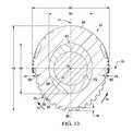
- FIG. 13is a cross sectional view taken along the line 13 - 13 of FIG. 1 ;
- FIG. 14is a flow chart depicting one example of a method of manufacturing the handle of FIG. 1 .
- a handle 20 for a razor cartridgeis shown in FIG. 1 to include a head 22 and a base portion 24 that can be grasped by a hand of a user to manipulate the head 22 .
- the head 22can include a cartridge engaging end 26 that is configured to facilitate coupling of the handle 20 to a razor cartridge 27 .
- the cartridge engaging end 26can be configured to receive (e.g., releasably couple to and interact with or be permanently attached to, in the case of a fully disposable type razor) a GILLETTE MACH3® cartridge.
- the cartridge engaging end 26can be configured to receive a variety of other suitable cartridges which may include other Gillette type cartridges, such as the GILLETTE FUSION RAZOR®.
- a cartridge engaging endcan be configured to receive a razor cartridge that is compatible with a DORCO® docking interface, an example of which is disclosed in U.S. Pat. No. 8,590,162, which is hereby incorporated by reference in its entirety.
- a cartridge engaging endcan be configured to receive a razor cartridge that is compatible with the AMERICAN SAFETY RAZOR® (ASR) docking interface an example of which is disclosed in U.S. Pat. No. 8,079,147, which is hereby incorporated by reference in its entirety.
- a cartridge engaging endcan be configured to receive a razor cartridge that is compatible with the HARRY'S RAZOR® cartridge docking interface.
- the base portion 24can comprise a right shell 30 , a left shell 32 , a rod 34 , a clip member 36 , and a cover layer 38 .
- the right shell 30 and the left shell 32can be releasably coupled together to form a body 40 that has a front end 42 and a rear end 44 .
- the right shell 30can define a plurality of holes 46 ( FIG. 4 ) and the left shell 32 can include a plurality of posts 48 ( FIG. 5 ) that can each be inserted into one of the holes 46 to facilitate releasable coupling of the right and left shells 30 , 32 together.
- the right and left shells 30 , 32can be releasably coupled with each other in any of a variety of suitable alternative manners (e.g., a shell can include both holes and posts). It is also to be appreciated that, although the body 40 is shown to be separated into right and left shells 30 , 32 , a body can be provided in any of a variety of arrangements including, for example, a unitary one-piece construction.
- an attachment end 50 of the head 22can be coupled with the front end 42 of the body 40 .
- the body 40 and the attachment end 50can include various features that are configured to facilitate coupling of the front end 42 of the body 40 with the attachment end 50 .
- the right shell 30 and left shell 32can each include respective pairs of slots 52 , 54 , each disposed at the front end 42 of the body 40 (see FIG. 3 ). When the right and left shells 30 , 32 are coupled together, each of the slots 52 of the right shell 30 can correspond with one of the slots 54 of the left shell 32 .
- the right shell 30 and left shell 32can also include respective pairs of through holes 56 , 58 .
- one of the through holes(e.g., 56 and 58 , respectively) is shown to be disposed between the slots (e.g., 52 and 54 , respectively) and the other of the through holes (e.g., 56 and 58 , respectively) is shown to be disposed rearwardly of the slots (e.g., 52 and 54 , respectively).
- the attachment end 50can comprise a stem 59 , a pair of protrusions 60 , and pairs of posts 62 .
- Each of the protrusions 60 and posts 62are shown to extend away from a centerline C 1 defined by the stem 59 in a substantially perpendicular direction from the centerline C 1 .
- the protrusions 60can extend away from the centerline C 1 in the same direction.
- the posts 62can extend away from the centerline C 1 in substantially opposite directions and substantially perpendicularly to the direction of the protrusions 60 .
- Each of the protrusions 60can correspond with one of the slots 52 , 54 defined by each of the right shell 30 and the left shell 32 .
- Each of the posts 62can correspond with one of the through holes 56 , 58 defined by each of the right shell 30 and the left shell 32 . It is to be appreciated that the head 22 and/or body 40 can be provided with any quantity and configuration of protrusion and slots that interact with one another and/or posts and through holes that interact with one another to facilitate coupling of the head 22 with the body 40 .
- each of the protrusions 60can extend into one of the slots 52 , 54 and each of the posts 62 can extend into one of the through holes 56 , 58 .
- the protrusions 60can be substantially square shaped such that when the right and left shells 30 , 32 are coupled together, the protrusions 60 can fit within the slots 52 , 54 and the square shape can prevent rotation of the stem 59 with respect to the body 40 .
- the posts 62can each include an enlarged portion 64 at a distal end.
- the enlarged portions 64can have a larger diameter than the through holes 56 , 58 .
- the right and left shells 30 , 32can be installed over the attachment end 50 and compressed together with enough force to push the enlarged portions 64 through the respective through holes 56 , 58 and to an exterior of the body 40 .
- the through holes 56 , 58 and/or the enlarged portions 64can be deformed as a result which can resiliently and releasably couple the right and left shells 30 , 32 together and to the attachment end 50 .
- coupling the right and left shells 30 , 32 together and to the attachment end 50 in this mannercan reinforce the interaction between the body 40 and the attachment end 50 such that the head 22 is less likely to separate from the body 40 when the handle 20 is mishandled (e.g., dropped) than in conventional arrangements.
- each of the head 22 the right shell 30 and the left shell 32can be formed of any of a variety of materials that are rigid enough to facilitate shaving with the handle 20 , including, for example, acrylonitrile butadiene styrene (ABS). It is also to be appreciated that any of the head 22 , the right shell 30 , and the left shell 32 can be formed of the same or different materials.
- ABSacrylonitrile butadiene styrene
- the right shell 30 and the left shell 32can each define respective right and left compartments 66 , 68 .
- the right and left compartments 66 , 68can cooperate to define a hollow interior 70 ( FIG. 13 ).
- the rod 34can be disposed within the hollow interior 70 .
- the rod 34 and the right and left compartments 66 , 68can interact with each other to prevent movement of the rod 34 inside of the hollow interior 70 .
- the rod 34can be configured to provide some linear rigidity to the base portion 24 and can be weighted to enhance the overall feel and balance to the handle 20 when the base portion 24 is grasped by a user.
- the rod 34can be formed of a metal, such as, for example, stainless steel, steel, or aluminum.
- the rod 34can be formed of a high density thermoplastic.
- the rod 34(and the body 40 ) can define a centerline C 2 that is substantially coaxial with the rod 34 .
- the rod 34can be spaced from the attachment end 50 along the centerline C 2 , such that a portion of the right and left shells 30 , 32 are disposed therebetween. This spacing can allow the head 22 to flex somewhat relative to the rod 34 , thereby alleviating some of the adverse effects that the rigidity of the rod 34 might otherwise have on the ability of the head 22 to resist separation of the head 22 from the body 40 .
- the centerline C 2can reside in an imaginary plane P 1 that bisects the head 22 into right and left portions 72 , 74 that are substantial mirror images of each other.
- a second imaginary plane P 2can be perpendicular to the first imaginary plane P 1 and the centerline C 2 can reside in the intersection between the first and second imaginary planes P 1 , P 2 .
- the right shell 30 and the left shell 32can cooperate to form a seam 76 that is substantially parallel with the centerline C 2 and that resides substantially within the first imaginary plane P 1 such that the right and left shells 30 , 32 are disposed on right and left sides of the handle 20 .
- the clip member 36can be releasably coupled with the rear end 44 of the body 40 .
- the clip member 36can be substantially U-shaped and can include a pair of arm members 78 ( FIG. 9 ) that are each substantially the same length.
- the right and left shells 30 , 32can cooperate to define a channel 80 at the rear end 44 of the body 40 that is substantially the same shape as the clip member 36 (e.g., U-shaped).
- the clip member 36can be disposed in the channel 80 such that the arm members 78 overlie a portion of the seam 76 .
- the arm members 78can include a plurality of recesses (e.g., 79 and 81 ). As illustrated in FIGS. 4 and 5 , the right and left shells 30 , 32 can include a plurality of projections 83 and 84 . When the clip member 36 is disposed within the channel 80 , the recesses 79 and 81 and the projections 83 and 84 , respectively, can interact to facilitate coupling or retention of the clip member 36 to the right and left shells 30 , 32 as well as releasable coupling of the right and left shells 30 , 32 together. As illustrated in FIG.
- the clip member 36can include a pair of plates 82 that are releasably secured to the arm members 78 .
- the pair of plates 82can be provided with product information (e.g., a logo or other marking) that identifies the razor or the handle 20 .
- product informatione.g., a logo or other marking
- the clip member 36can be spaced from the rod 34 (e.g., along each of the centerline C 2 , the first imaginary plane P 1 ( FIG. 3 ), and the second imaginary plane P 2 ( FIG. 3 ).
- the cover layer 38can be substantially hollow and can at least partially surround the body 40 between the front end 42 and the rear end 44 .
- the cover layer 38is shown to entirely surround the body 40 between the front end 42 and the channel 80 .
- a portion of the cover layer 38 that is disposed at the rear end 44 of the body 40can extend up to, but not into, the channel 80 and can be routed around the channel 80 to enhance the overall aesthetics of the rear end 44 of the body 40 when the clip member 36 is installed.
- the cover layer 38accordingly does not interfere with installation of the clip member 36 into the channel 80 .
- the cover layer 38can be formed of any of a variety of suitable materials and can be overmolded, or otherwise applied, to the body 40 in such a manner that the cover layer 38 is formed to the body 40 .
- the cover layer 38can be comprised of an SEBS-based thermoplastic elastomer (TPE) that has a hardness of about 15-20 Shore A and is configured to adhere to ABS plastic.
- TPESEBS-based thermoplastic elastomer
- the TPEcan encourage a user's gripping of the base portion 24 more effectively than other conventional razor handle arrangements.
- the TPEcan be configured to have substantially the same coefficient of friction when dry and when exposed to water.
- the right and left shells 30 , 32can each comprise a pair of through holes 86 at base portion 24 .
- the material of the cover layer 38can extend into (e.g., creep), and in some embodiments extend through, the through holes 86 to facilitate securement of the cover layer 38 to the rear end 44 of the body 40 .
- the front end 42 of the body 40is shown to be narrower at the through holes 56 , 58 than the rest of the body 40 (e.g., towards the rear end 44 ). As such, the cover layer 38 can be narrower at the front end 42 which can effectively secure the cover layer 38 to the front end 42 of the body 40 .
- the cover layer 38can have a maximum thickness of between about 2.75 mm and 3.5 mm, although any of a variety of thicknesses are contemplated. It is to be appreciated that any quantity and configuration of through holes can be provided along the body 40 (i.e., at or between the front and rear ends 42 , 44 ) through which the cover layer 38 can extend.
- the cover layer 38can be formed of a material (e.g., the TPE described above) that is substantially translucent.
- the cover layer 38can be less opaque than the body 40 such that the body can be viewed through the cover layer 38 .
- the body 40can accordingly be provided with indicia (e.g., a product name, logo, or other markings) that can be visible through the cover layer 38 .
- the cover layer 38can be tinted to provide an aesthetically pleasing color to the cover layer 38 while maintaining its translucence. It is to be appreciated that the cover layer 38 can comprise any of a variety of suitable additional or alternative materials. Some examples of suitable materials are described in U.S. Patent Application Publication Nos.
- the cover layer 38can include a base surface 88 having a plurality of projections 90 extending therefrom.
- Each of the plurality of projections 90can have an upper surface 92 that is substantially planar.
- the projections 90are shown to be substantially frusto-pyramidal shaped (i.e., a pyramidal shape missing its top portion such that the upper surface 92 and the lower surface of the shape are parallel), but in other embodiments, the projections 90 can be any of a variety of suitable alternative shapes with substantially planar upper surfaces.
- the upper surface 92can reside in an imaginary plane (e.g., P 3 in FIGS. 12 and 13 ) that is substantially perpendicular to a radial line (e.g., R 1 in FIGS. 12 and 13 ) extending from the centerline C 2 .
- the projections 90can be distributed along the cover layer 38 in a pattern that enhances gripping of the base portion 24 by a user's hand. Each of the projections 90 can define a height relative to the base surface 88 . In some embodiments, at certain locations along the cover layer 38 , the height of the projections 90 can be different from each immediately adjacent projection 90 to provide a desired gripping contour/profile at that location. Referring now to FIG. 12 , a plurality of projections 90 is shown that are distributed longitudinally along the cover layer 38 (e.g., intersected by an imaginary plane in which the centerline C 2 resides). One of the projections 90 is shown to have a height H 1 that is greater than another projection 90 having a height H 2 .
- the respective heights of the projections 90 that are interposed therebetweencan gradually diminish in the direction of arrow A 1 , such that the gripping contour defined by those projections 90 tapers in the direction of arrow A 1 .
- Another of the projections 90is shown have a height H 3 that is greater than another projection 90 having a height H 4 .
- the respective heights of the projections 90 that are interposed therebetweencan gradually diminish in the direction of arrow A 2 , such that the gripping contour defined by those projections 90 tapers in the direction of arrow A 2 (e.g., towards the rear end 44 of the body 40 ).
- a plurality of projections 90is shown that are distributed radially along the cover layer 38 (e.g., intersected by an imaginary plane that is perpendicular to the centerline C 2 , such as, for example, imaginary plane P 2 ).
- One of the projections 90is shown to have a height H 5 that is greater than other projections 90 having respective heights of H 6 and H 7 .
- the respective heights of the projections 90 that are interposed between the projection 90 having the height H 5 and the projections having the heights H 6 and H 7can gradually diminish in the direction of arrows A 3 and A 4 , such that the gripping contour defined by those projections 90 tapers in the direction of the arrows A 3 and A 4 towards a top of the body 40 such that the cover layer 38 feels thicker along the bottom of the body 40 .
- the projections 90can be configured to achieve any of a variety of different contours along the cover layer 38 .
- the cover layer 38can be oval-shaped.
- the cover layer 38can have a maximum height H 8 measured along the imaginary plane P 1 and a maximum width W 1 measured along the imaginary plane P 2 .
- the ratio of the maximum height H 8 to the maximum width W 1can be a ratio of less than 2, preferably a ratio between 2 and 1, and most preferably a ratio of about 15 to about 13.5, respectively (e.g., or a ratio of about 1.11).
- the body 40can additionally or alternatively be oval-shaped.
- the body 40can have a maximum height H 9 measured along the imaginary plane P 1 and a maximum width W 2 measured along the imaginary plane P 2 .
- the ratio of the maximum height H 9 to the maximum width W 2can be less than about 2, and preferably about 2 to about 1, and most preferably a ratio of about 15 to about 13.5, respectively (e.g., or a ratio of about 1.11). It is to be appreciated that the maximum height and width of the cover layer and/or the body can be measured along any of a variety of locations around the base portion 24 such that the ovular shape of the cover layer and/or body can be any particular orientation.
- the rod 34can be installed in the right shell 30 by inserting the rod 34 into the right compartment 66 ( 200 ).
- the attachment end 50 of the head 22can be installed in the right shell 30 by aligning the protrusions 60 and the posts 62 with the slots 52 and the through holes 56 , respectively, of the right shell 30 ( 205 , 210 ) and pressing the attachment end 50 into position ( 215 ).
- the clip member 36can then be installed onto the right shell 30 ( 210 ) by compressing the clip member 36 such that the recesses 79 and 81 on the clip member 36 engage the projections 83 and 84 , respectively, on the right shell 30 to couple the clip member 36 to the right shell 30 .
- the left shell 32can then be positioned over the right shell 30 ( 225 ) such that the protrusions 60 and the posts 62 align with the slots 54 and the through holes 58 , respectively, of the left shell 32 .
- the right and left shells 30 , 32can then be compressed together (e.g., manually or via automation) ( 230 ) which can cause the recesses 79 and 81 on the clip member 36 to engage the projections 83 and 84 , respectively, on the left shell 32 and can cause the enlarged portions 64 of the posts 62 to extend through the through holes 56 , 58 of the first shell 30 and the second shell 32 , respectively.
- the body 40can then be coated with the cover layer 38 ( 235 ).
- the coatingmay be an overmolded, or otherwise applied, to the body 40 in such a manner that the cover layer 38 is formed to the body 40 .
- the cover layermay be formed with protrusions.
- Every maximum numerical limitation given throughout this specificationincludes every lower numerical limitation, as if such lower numerical limitations were expressly written herein. Every minimum numerical limitation given throughout this specification includes every higher numerical limitation, as if such higher numerical limitations were expressly written herein. Every numerical range given throughout this specification includes every narrower numerical range that falls within such broader numerical range, as if such narrower numerical ranges were all expressly written herein.
Landscapes
- Engineering & Computer Science (AREA)
- Life Sciences & Earth Sciences (AREA)
- Forests & Forestry (AREA)
- Mechanical Engineering (AREA)
- Manufacturing & Machinery (AREA)
- Packaging Of Annular Or Rod-Shaped Articles, Wearing Apparel, Cassettes, Or The Like (AREA)
Abstract
Description
- A. A handle for a razor cartridge, the handle comprising:
- a head having a cartridge engaging end and an attachment end;
- a body formed of a first material and defining a centerline, the body having a front end and a rear end, wherein the front end is coupled with the attachment end; and
- a cover layer at least partially overlying the body and formed of a second material, the cover layer comprising a base surface having a plurality of projections extending therefrom, wherein each projection of the plurality of projections has an upper surface that is substantially planar.
- B. The handle according to Paragraph A, wherein:
- each projection of the plurality of projections is interposed between a pair of immediately adjacent projections;
- each projection of the plurality of projections defines a height; and
- the height of each projection of the plurality of projections is:
- greater than the height of one of the immediately adjacent projections; and
- less than the height of the other immediately adjacent projection.
- C. The handle according to Paragraph B, wherein:
- the centerline resides in a first imaginary plane;
- each projection of the plurality of projections and pair of immediately adjacent projections is intersected by the first imaginary plane; and
- the height of each projection of the plurality of projections is:
- greater than the height of one of the immediately adjacent projections along the first imaginary plane; and
- less than the height of the other immediately adjacent projection along the first imaginary plane.
- D. The handle according to Paragraph C, wherein:
- the centerline is perpendicular to a second imaginary plane;
- each projection of the plurality of projections and pair of immediately adjacent projections is intersected by the second imaginary plane; and
- the height of each projection of the plurality of projections is:
- greater than the height of one of the immediately adjacent projections along the second imaginary plane; and
- less than the height of the other immediately adjacent projection along the second imaginary plane.
- E. The handle according to any of Paragraphs A-D, wherein each projection of the plurality of projections is frusto-pyramidal shaped.
- F. The handle according to any of Paragraphs A-E, wherein the body comprises a first shell and a second shell that are releasably coupled together.
- G. The handle according to Paragraph F, wherein:
- the first shell and the second shell each define one or more through holes; and
- the cover layer extends into each of the through holes.
- H. The handle according to any of Paragraphs A-G, wherein the second material comprises thermoplastic elastomer.
- I. The handle according to any of Paragraphs A-H, wherein the second material has a durometer value of between about 15 and about 20.
- J. The handle according to any of Paragraphs A-I further comprising a rod, wherein:
- the body defines a hollow interior;
- the rod is disposed in the hollow interior of the body; and
- the centerline extends through the rod.
- K. The handle according to Paragraph J, wherein the rod comprises one or more of steel, stainless steel and aluminum.
- L. The handle according to any of Paragraphs K-L further comprising a clip member coupled with the rear end of the body, wherein the rod is spaced from the clip member.
- M. The handle according to any of Paragraphs A-L, wherein the cover layer entirely circumferentially surrounds at least a portion of the body.
- N. The handle according to any of Paragraphs A-M, wherein the second material is substantially translucent.
- O. The handle according to any of Paragraphs A-N, wherein the second material is less opaque than the first material.
- P. The handle according to any of Paragraphs A-O, wherein each projection of the plurality of projections has an upper surface that resides in an imaginary plane that is substantially perpendicular to a radial line extending from the centerline.
- A. A handle for a razor cartridge, the handle comprising:
Claims (15)
Priority Applications (3)
| Application Number | Priority Date | Filing Date | Title |
|---|---|---|---|
| US15/234,998US10414058B2 (en) | 2016-08-11 | 2016-08-11 | Handle for a razor |
| PCT/US2017/045025WO2018031320A1 (en) | 2016-08-11 | 2017-08-02 | Handle for a razor |
| EP17751933.7AEP3496913B1 (en) | 2016-08-11 | 2017-08-02 | Handle for a razor |
Applications Claiming Priority (1)
| Application Number | Priority Date | Filing Date | Title |
|---|---|---|---|
| US15/234,998US10414058B2 (en) | 2016-08-11 | 2016-08-11 | Handle for a razor |
Publications (2)
| Publication Number | Publication Date |
|---|---|
| US20180043551A1 US20180043551A1 (en) | 2018-02-15 |
| US10414058B2true US10414058B2 (en) | 2019-09-17 |
Family
ID=59593210
Family Applications (1)
| Application Number | Title | Priority Date | Filing Date |
|---|---|---|---|
| US15/234,998Active2036-12-19US10414058B2 (en) | 2016-08-11 | 2016-08-11 | Handle for a razor |
Country Status (3)
| Country | Link |
|---|---|
| US (1) | US10414058B2 (en) |
| EP (1) | EP3496913B1 (en) |
| WO (1) | WO2018031320A1 (en) |
Cited By (2)
| Publication number | Priority date | Publication date | Assignee | Title |
|---|---|---|---|---|
| US11020867B2 (en)* | 2019-03-15 | 2021-06-01 | The Gillette Company Llc | Razor handle with a rotatable portion |
| US11130247B2 (en)* | 2016-08-11 | 2021-09-28 | The Gillette Company Llc | Handle for a razor |
Families Citing this family (1)
| Publication number | Priority date | Publication date | Assignee | Title |
|---|---|---|---|---|
| EP3878615B1 (en)* | 2019-08-09 | 2024-12-18 | Wenzhou Mers R&D Ltd. | Interconnecting member and handle for shaver |
Citations (53)
| Publication number | Priority date | Publication date | Assignee | Title |
|---|---|---|---|---|
| US3770950A (en) | 1972-07-31 | 1973-11-06 | Schick Inc | Electric light system for a motor-driven appliance |
| US4837892A (en) | 1988-03-04 | 1989-06-13 | Conair Corporation | Cushioned handle structure for personal care appliances |
| US4841638A (en) | 1987-09-04 | 1989-06-27 | Pumpkin, Ltd. | Hand-held cutting tool apparatus |
| US4949457A (en) | 1988-08-03 | 1990-08-21 | Warner-Lambert Company | Soft resilient razor handle |
| US4980973A (en) | 1990-02-28 | 1991-01-01 | Lee Chin Piao | Shaver having a clipper |
| US5107590A (en) | 1991-03-26 | 1992-04-28 | Warner-Lambert Company | Razor handle |
| US5157835A (en) | 1991-06-26 | 1992-10-27 | The Gillette Company | Safety razor handle assembly |
| US5403534A (en) | 1991-09-26 | 1995-04-04 | Tritec International Corporation | Disposable razor |
| US5497551A (en)* | 1994-10-13 | 1996-03-12 | The Gillette Company | Razor handle assembly |
| US5784790A (en)* | 1996-04-10 | 1998-07-28 | The Gillette Company | Shaving razor and method |
| US6273626B1 (en) | 1998-10-09 | 2001-08-14 | Zebra Co., Ltd. | Grip for a writing instrument |
| US6595900B1 (en) | 1998-02-02 | 2003-07-22 | Arnold J. Cook | Jump rope |
| US6610382B1 (en) | 1998-10-05 | 2003-08-26 | 3M Innovative Properties Company | Friction control article for wet and dry applications |
| US6652941B1 (en) | 2000-09-27 | 2003-11-25 | Bic Corporation | Grip element and method of manufacture thereof |
| US20040216311A1 (en) | 2003-03-28 | 2004-11-04 | Eveready Battery Company, Inc. | Razor handle assembly |
| US6880253B1 (en) | 2000-06-23 | 2005-04-19 | Bic Violex S.A. | Razor with a movable shaving head |
| US20060052535A1 (en) | 2004-01-06 | 2006-03-09 | Manoj Ajbani | Thermoplastic elastomer composition |
| US7047591B2 (en) | 2002-09-20 | 2006-05-23 | Colgate-Palmolive Company | Oral care implement |
| US20060242847A1 (en) | 2005-04-05 | 2006-11-02 | Eveready Battery Company, Inc. | Razor handle and method for making same |
| US20060272154A1 (en) | 2005-06-02 | 2006-12-07 | Brevard Alfred S | Disposable gel-dispensing razor |
| US20070050983A1 (en)* | 2005-09-06 | 2007-03-08 | Fred Schnak | Razors |
| US20070050997A1 (en)* | 2005-09-06 | 2007-03-08 | Fred Schnak | Razors |
| US20070143942A1 (en) | 2005-12-23 | 2007-06-28 | Polyworks, Inc. | Handle with soft gel cushioning member |
| US7383619B2 (en) | 2003-11-18 | 2008-06-10 | Trisa Holding Ag | Handle body for body care implements |
| US20080201966A1 (en) | 2005-06-28 | 2008-08-28 | Bic-Violex Sa | Razor Handle Provided with an Improved Grip |
| US20090035524A1 (en) | 2007-04-13 | 2009-02-05 | Polyworks, Inc. | Impact and vibration absorbing body-contacting medallions, methods of using and methods of making |
| US20090039688A1 (en) | 2007-04-13 | 2009-02-12 | Polyworks, Inc. | Cushioning medallions, methods of making and methods of using |
| US20090142551A1 (en) | 2007-11-29 | 2009-06-04 | Polyworks, Inc. | Composite Material, Method of Making and Articles Formed Thereby |
| US20090163932A1 (en) | 2007-12-25 | 2009-06-25 | Panasonic Electric Works Co., Ltd. | Electric hair remover |
| US20090293292A1 (en) | 2008-05-27 | 2009-12-03 | Christopher Ramm | Resilient razor handle |
| US20100005669A1 (en)* | 2008-07-14 | 2010-01-14 | Florina Winter | Razor Handle |
| US7685720B2 (en) | 2004-09-07 | 2010-03-30 | Bic-Violex S.A. | Razor handle and shaver including such a handle |
| US20100263219A1 (en) | 2008-12-17 | 2010-10-21 | Kempker Jeffrey A | Tool with ergonomic handle and replaceable cutter head |
| US7827704B2 (en) | 2006-02-28 | 2010-11-09 | Polyworks, Incorporated | Methods of making polymeric articles and polymeric articles formed thereby |
| US20100298807A1 (en) | 2005-01-24 | 2010-11-25 | Akzo Nobel N.V. | Applicator for inserting an implant |
| US7861419B2 (en)* | 2005-06-28 | 2011-01-04 | Bic Violex Sa | Ergonomic razor handle provided with an improved grip |
| US20110030229A1 (en) | 2008-04-11 | 2011-02-10 | Ioannis Marios Psimadas | Razor handle having a retractable razor head carrier and razor having such a handle |
| US20110035950A1 (en) | 2009-08-12 | 2011-02-17 | Terence Gordon Royle | Safety razor with rotational movement and locking button |
| US20110256353A1 (en) | 2005-12-23 | 2011-10-20 | Polyworks, Inc. | Methods of making polymeric articles and polymeric articles formed thereby |
| US8079147B2 (en) | 2008-02-27 | 2011-12-20 | American Safety Razor | Shaving system |
| US8151468B2 (en) | 2008-09-26 | 2012-04-10 | The Gillette Company | Handle for shaving razors having improved grip |
| US8205341B2 (en) | 2007-10-01 | 2012-06-26 | United States Gypsum Company | Tool with replaceable blade |
| US20120168439A1 (en) | 2011-01-05 | 2012-07-05 | Steven Francis Quigley | Wet friction material for closures for product containers |
| US20120167401A1 (en) | 2011-01-05 | 2012-07-05 | Steven Francis Quigley | Wet friction materials for hair removal devices |
| US20120246947A1 (en) | 2011-03-28 | 2012-10-04 | Dong Fang | Hand Held Device Having A Rotational Axis |
| US8507061B2 (en) | 2011-01-05 | 2013-08-13 | The Gillette Company | Wet friction material for blow molded articles |
| US20130291390A1 (en) | 2012-05-01 | 2013-11-07 | The Gillette Company | Handle for a shaving razor |
| US8590162B2 (en) | 2007-05-31 | 2013-11-26 | Dorco Co., Ltd. | Shaver |
| US20140047656A1 (en) | 2011-11-22 | 2014-02-20 | The Procter & Gamble Company | Method for producing a toothbrush handle having an inner cavity |
| US20140173853A1 (en) | 2011-08-05 | 2014-06-26 | Trisa Holding Ag | Method for producing a toothbrush, and toothbrush |
| US20150266192A1 (en)* | 2014-03-20 | 2015-09-24 | Rolling Razor, Inc. | Shaving razor interconnection mechanism and method of making simplified interconnection |
| US20150290822A1 (en)* | 2012-11-06 | 2015-10-15 | Kai R&D Center Co., Ltd. | Razor |
| US20170036363A1 (en) | 2014-04-16 | 2017-02-09 | Bic-Violex Sa | Handles for shavers to be releasably connected to shaving cartridges |
- 2016
- 2016-08-11USUS15/234,998patent/US10414058B2/enactiveActive
- 2017
- 2017-08-02EPEP17751933.7Apatent/EP3496913B1/enactiveActive
- 2017-08-02WOPCT/US2017/045025patent/WO2018031320A1/ennot_activeCeased
Patent Citations (55)
| Publication number | Priority date | Publication date | Assignee | Title |
|---|---|---|---|---|
| US3770950A (en) | 1972-07-31 | 1973-11-06 | Schick Inc | Electric light system for a motor-driven appliance |
| US4841638A (en) | 1987-09-04 | 1989-06-27 | Pumpkin, Ltd. | Hand-held cutting tool apparatus |
| US4837892A (en) | 1988-03-04 | 1989-06-13 | Conair Corporation | Cushioned handle structure for personal care appliances |
| US4949457A (en) | 1988-08-03 | 1990-08-21 | Warner-Lambert Company | Soft resilient razor handle |
| US4980973A (en) | 1990-02-28 | 1991-01-01 | Lee Chin Piao | Shaver having a clipper |
| US5107590A (en) | 1991-03-26 | 1992-04-28 | Warner-Lambert Company | Razor handle |
| US5157835A (en) | 1991-06-26 | 1992-10-27 | The Gillette Company | Safety razor handle assembly |
| US5403534A (en) | 1991-09-26 | 1995-04-04 | Tritec International Corporation | Disposable razor |
| US5497551A (en)* | 1994-10-13 | 1996-03-12 | The Gillette Company | Razor handle assembly |
| US5784790A (en)* | 1996-04-10 | 1998-07-28 | The Gillette Company | Shaving razor and method |
| US6595900B1 (en) | 1998-02-02 | 2003-07-22 | Arnold J. Cook | Jump rope |
| US6610382B1 (en) | 1998-10-05 | 2003-08-26 | 3M Innovative Properties Company | Friction control article for wet and dry applications |
| US6273626B1 (en) | 1998-10-09 | 2001-08-14 | Zebra Co., Ltd. | Grip for a writing instrument |
| US6880253B1 (en) | 2000-06-23 | 2005-04-19 | Bic Violex S.A. | Razor with a movable shaving head |
| US6652941B1 (en) | 2000-09-27 | 2003-11-25 | Bic Corporation | Grip element and method of manufacture thereof |
| US7047591B2 (en) | 2002-09-20 | 2006-05-23 | Colgate-Palmolive Company | Oral care implement |
| US20040216311A1 (en) | 2003-03-28 | 2004-11-04 | Eveready Battery Company, Inc. | Razor handle assembly |
| US7383619B2 (en) | 2003-11-18 | 2008-06-10 | Trisa Holding Ag | Handle body for body care implements |
| US20060052535A1 (en) | 2004-01-06 | 2006-03-09 | Manoj Ajbani | Thermoplastic elastomer composition |
| US7685720B2 (en) | 2004-09-07 | 2010-03-30 | Bic-Violex S.A. | Razor handle and shaver including such a handle |
| US20100298807A1 (en) | 2005-01-24 | 2010-11-25 | Akzo Nobel N.V. | Applicator for inserting an implant |
| US20060242847A1 (en) | 2005-04-05 | 2006-11-02 | Eveready Battery Company, Inc. | Razor handle and method for making same |
| US20060272154A1 (en) | 2005-06-02 | 2006-12-07 | Brevard Alfred S | Disposable gel-dispensing razor |
| US20080201966A1 (en) | 2005-06-28 | 2008-08-28 | Bic-Violex Sa | Razor Handle Provided with an Improved Grip |
| US7861419B2 (en)* | 2005-06-28 | 2011-01-04 | Bic Violex Sa | Ergonomic razor handle provided with an improved grip |
| US20070050983A1 (en)* | 2005-09-06 | 2007-03-08 | Fred Schnak | Razors |
| US20070050997A1 (en)* | 2005-09-06 | 2007-03-08 | Fred Schnak | Razors |
| US20070143942A1 (en) | 2005-12-23 | 2007-06-28 | Polyworks, Inc. | Handle with soft gel cushioning member |
| US20110256353A1 (en) | 2005-12-23 | 2011-10-20 | Polyworks, Inc. | Methods of making polymeric articles and polymeric articles formed thereby |
| US7827704B2 (en) | 2006-02-28 | 2010-11-09 | Polyworks, Incorporated | Methods of making polymeric articles and polymeric articles formed thereby |
| US20090039688A1 (en) | 2007-04-13 | 2009-02-12 | Polyworks, Inc. | Cushioning medallions, methods of making and methods of using |
| US20110233973A1 (en) | 2007-04-13 | 2011-09-29 | Polyworks, Inc. | Cushioning medallions, methods of making and methods of using |
| US20090035524A1 (en) | 2007-04-13 | 2009-02-05 | Polyworks, Inc. | Impact and vibration absorbing body-contacting medallions, methods of using and methods of making |
| US8590162B2 (en) | 2007-05-31 | 2013-11-26 | Dorco Co., Ltd. | Shaver |
| US8205341B2 (en) | 2007-10-01 | 2012-06-26 | United States Gypsum Company | Tool with replaceable blade |
| US20090142551A1 (en) | 2007-11-29 | 2009-06-04 | Polyworks, Inc. | Composite Material, Method of Making and Articles Formed Thereby |
| US20090163932A1 (en) | 2007-12-25 | 2009-06-25 | Panasonic Electric Works Co., Ltd. | Electric hair remover |
| US8079147B2 (en) | 2008-02-27 | 2011-12-20 | American Safety Razor | Shaving system |
| US20110030229A1 (en) | 2008-04-11 | 2011-02-10 | Ioannis Marios Psimadas | Razor handle having a retractable razor head carrier and razor having such a handle |
| US20090293292A1 (en) | 2008-05-27 | 2009-12-03 | Christopher Ramm | Resilient razor handle |
| US20100005669A1 (en)* | 2008-07-14 | 2010-01-14 | Florina Winter | Razor Handle |
| US8151468B2 (en) | 2008-09-26 | 2012-04-10 | The Gillette Company | Handle for shaving razors having improved grip |
| US8151469B2 (en) | 2008-09-26 | 2012-04-10 | The Gillette Company | Handle for shaving razors having improved grip |
| US20100263219A1 (en) | 2008-12-17 | 2010-10-21 | Kempker Jeffrey A | Tool with ergonomic handle and replaceable cutter head |
| US20110035950A1 (en) | 2009-08-12 | 2011-02-17 | Terence Gordon Royle | Safety razor with rotational movement and locking button |
| US20120167401A1 (en) | 2011-01-05 | 2012-07-05 | Steven Francis Quigley | Wet friction materials for hair removal devices |
| US8507061B2 (en) | 2011-01-05 | 2013-08-13 | The Gillette Company | Wet friction material for blow molded articles |
| US20120168439A1 (en) | 2011-01-05 | 2012-07-05 | Steven Francis Quigley | Wet friction material for closures for product containers |
| US20120246947A1 (en) | 2011-03-28 | 2012-10-04 | Dong Fang | Hand Held Device Having A Rotational Axis |
| US20140173853A1 (en) | 2011-08-05 | 2014-06-26 | Trisa Holding Ag | Method for producing a toothbrush, and toothbrush |
| US20140047656A1 (en) | 2011-11-22 | 2014-02-20 | The Procter & Gamble Company | Method for producing a toothbrush handle having an inner cavity |
| US20130291390A1 (en) | 2012-05-01 | 2013-11-07 | The Gillette Company | Handle for a shaving razor |
| US20150290822A1 (en)* | 2012-11-06 | 2015-10-15 | Kai R&D Center Co., Ltd. | Razor |
| US20150266192A1 (en)* | 2014-03-20 | 2015-09-24 | Rolling Razor, Inc. | Shaving razor interconnection mechanism and method of making simplified interconnection |
| US20170036363A1 (en) | 2014-04-16 | 2017-02-09 | Bic-Violex Sa | Handles for shavers to be releasably connected to shaving cartridges |
Non-Patent Citations (11)
| Title |
|---|
| PCT International Search Report with Written Opinion in corresponding Int'l appln. PCT/US2017/045025 dated Sep. 26, 2017. |
| U.S. Appl. No. 15/234,986, filed Aug. 11, 2016, Hong Lu et al. |
| U.S. Appl. No. 15/235,006, filed Aug. 11, 2016, Hong Lu et al. |
| U.S. Appl. No. 15/235,014, filed Aug. 11, 2016, Hong Lu et al. |
| U.S. Appl. No. 15/235,019, filed Aug. 11, 2016, Hong Lu et al. |
| U.S. Appl. No. 15/235,026, filed Aug. 11, 2016, Hong Lu et al. |
| U.S. Appl. No. 15/235,033, filed Aug. 11, 2016, Hong Lu et al. |
| U.S. Appl. No. 15/235,044, filed Aug. 11, 2016, Hong Lu et al. |
| U.S. Appl. No. 15/235,049, filed Aug. 11, 2016, Hong Lu et al. |
| U.S. Appl. No. 15/235,056, filed Aug. 11, 2016, Hong Lu et al. |
| U.S. Appl. No. 15/235,059, filed Aug. 11, 2016, Hong Lu et al. |
Cited By (2)
| Publication number | Priority date | Publication date | Assignee | Title |
|---|---|---|---|---|
| US11130247B2 (en)* | 2016-08-11 | 2021-09-28 | The Gillette Company Llc | Handle for a razor |
| US11020867B2 (en)* | 2019-03-15 | 2021-06-01 | The Gillette Company Llc | Razor handle with a rotatable portion |
Also Published As
| Publication number | Publication date |
|---|---|
| EP3496913B1 (en) | 2020-09-23 |
| WO2018031320A1 (en) | 2018-02-15 |
| EP3496913A1 (en) | 2019-06-19 |
| US20180043551A1 (en) | 2018-02-15 |
Similar Documents
| Publication | Publication Date | Title |
|---|---|---|
| US20180043553A1 (en) | Handle for a razor | |
| AU2020220121B2 (en) | Handle for a razor | |
| AU2017310404B2 (en) | Handle for a razor | |
| US10414058B2 (en) | Handle for a razor | |
| AU2017310403B2 (en) | A head for a razor handle | |
| US20180043558A1 (en) | Handle for a razor | |
| US11130247B2 (en) | Handle for a razor | |
| US11285630B2 (en) | Handle for a razor | |
| US20180043550A1 (en) | Handle for a razor | |
| AU2020281027A1 (en) | Handle for a razor | |
| US20180043557A1 (en) | Handle for a razor |
Legal Events
| Date | Code | Title | Description |
|---|---|---|---|
| AS | Assignment | Owner name:THE GILLETTE COMPANY LLC, MASSACHUSETTS Free format text:MERGER AND CHANGE OF NAME;ASSIGNORS:THE GILLETTE COMPANY;THE GILLETTE COMPANY LLC;REEL/FRAME:040145/0258 Effective date:20160901 | |
| AS | Assignment | Owner name:THE GILLETTE COMPANY LLC, MASSACHUSETTS Free format text:ASSIGNMENT OF ASSIGNORS INTEREST;ASSIGNORS:LU, HONG;WITKUS, STEPHEN CHARLES;FORTI, ALEXANDER STEPHEN;SIGNING DATES FROM 20160908 TO 20160927;REEL/FRAME:039993/0562 Owner name:YAMADA ELECTRIC IND. CO., LTD.,, CHINA Free format text:ASSIGNMENT OF ASSIGNORS INTEREST;ASSIGNOR:GONG, HUIBIN;REEL/FRAME:040319/0512 Effective date:20160905 Owner name:THE GILLETTE COMPANY LLC, MASSACHUSETTS Free format text:ASSIGNMENT OF ASSIGNORS INTEREST;ASSIGNOR:YAMADA ELECTRIC IND. CO., LTD.,;REEL/FRAME:040319/0556 Effective date:20160927 | |
| STPP | Information on status: patent application and granting procedure in general | Free format text:RESPONSE TO NON-FINAL OFFICE ACTION ENTERED AND FORWARDED TO EXAMINER | |
| STPP | Information on status: patent application and granting procedure in general | Free format text:NOTICE OF ALLOWANCE MAILED -- APPLICATION RECEIVED IN OFFICE OF PUBLICATIONS | |
| STPP | Information on status: patent application and granting procedure in general | Free format text:PUBLICATIONS -- ISSUE FEE PAYMENT RECEIVED | |
| STPP | Information on status: patent application and granting procedure in general | Free format text:PUBLICATIONS -- ISSUE FEE PAYMENT VERIFIED | |
| STCF | Information on status: patent grant | Free format text:PATENTED CASE | |
| MAFP | Maintenance fee payment | Free format text:PAYMENT OF MAINTENANCE FEE, 4TH YEAR, LARGE ENTITY (ORIGINAL EVENT CODE: M1551); ENTITY STATUS OF PATENT OWNER: LARGE ENTITY Year of fee payment:4 |