US10413742B2 - Defibrillator patient monitoring pod - Google Patents
Defibrillator patient monitoring podDownload PDFInfo
- Publication number
- US10413742B2 US10413742B2US14/069,021US201314069021AUS10413742B2US 10413742 B2US10413742 B2US 10413742B2US 201314069021 AUS201314069021 AUS 201314069021AUS 10413742 B2US10413742 B2US 10413742B2
- Authority
- US
- United States
- Prior art keywords
- pod
- patient
- data
- lead
- port
- Prior art date
- Legal status (The legal status is an assumption and is not a legal conclusion. Google has not performed a legal analysis and makes no representation as to the accuracy of the status listed.)
- Active, expires
Links
Images


Classifications
- A—HUMAN NECESSITIES
- A61—MEDICAL OR VETERINARY SCIENCE; HYGIENE
- A61N—ELECTROTHERAPY; MAGNETOTHERAPY; RADIATION THERAPY; ULTRASOUND THERAPY
- A61N1/00—Electrotherapy; Circuits therefor
- A61N1/18—Applying electric currents by contact electrodes
- A61N1/32—Applying electric currents by contact electrodes alternating or intermittent currents
- A61N1/38—Applying electric currents by contact electrodes alternating or intermittent currents for producing shock effects
- A61N1/39—Heart defibrillators
- A61N1/3925—Monitoring; Protecting
Definitions
- the teachingsrelates to medical devices, and in particular, to defibrillation/monitor systems having a detachable pod with leads.
- SCAsudden cardiac arrest
- SCAoccurs when the heart stops pumping blood. Usually SCA is due to abnormal electrical activity in the heart, resulting in an abnormal rhythm (arrhythmia). One such abnormal rhythm, ventricular fibrillation (VF), is caused by abnormal and very fast electrical activity in the heart. During VF the heart cannot pump blood effectively. Because blood may no longer be pumping effectively during VF, the chances of surviving decreases with time after the onset of the emergency. Brain damage can occur after the brain is deprived of oxygen for four to six minutes.
- VFVF
- the shockclears the heart of the abnormal electrical activity (in a process called “defibrillation”) by depolarizing a critical mass of myocardial cells to allow spontaneous organized myocardial depolarization to resume.
- Cardiac arrestis a life-threatening medical condition that may be treated with external defibrillation.
- External defibrillationincludes applying electrodes to the patient's chest and delivering an electric shock to the patient to depolarize the patient's heart and restore normal sinus rhythm. The chance a patient's heart can be successfully defibrillated increases significantly if a defibrillation pulse is applied quickly.
- a paramedicIn a scenario where a paramedic is responding to an emergency call with a non-specific patient condition, for example, there has been a car accident.
- the paramedicwill typically carry his or her own defibrillator/monitor, a gurney, and drug box, and other supplies considered essential. If, perhaps, the car has driven off an embankment, the paramedic will have a long distance to run with all this equipment. This slows the response time to a call where someone may be bleeding to death. Smaller lighter equipment is always demanded by paramedics to save them time and effort, and allow them to get to the scene earlier.
- the number of cables and their similarity in color or dissimilarity in lengthcan all contribute to delays in treating or transferring the patient and can restrict the paramedics mobility when treating the patient in a confined space. Additionally, delays may be created with cables having become tangled, or even cut, from their previous uses.
- the prior arthas tried to solve this problem by providing a wireless module that transmits data to a patient monitor, such as the MobiMed offered for Sale by Ortivus.
- a patient monitorsuch as the MobiMed offered for Sale by Ortivus.
- this devicedoes not include a defibrillator and does not have the capability to provide any therapeutic functions such as pacing, defibrillation or synchronous cardioversion without attaching another monitor/defibrillator to the patient, which further increases the complexity and ambulance provider cost.
- the Ortivus patient moduledoes not offer replaceable batteries so functionality is severely limited if a reliable source of battery charging is not available, or if the transport time is excessively long.
- the Ortivus devicedoes not offer a display to allow visual monitoring of the waveforms or vital signs if the other module is out of range or obscured.
- a patient parameter monitoring pod in embodiments of the teachingsmay include one or more of the following features: (a) portable housing containing a power supply, (b) a patient parameter module connectable to a patient via lead cables to collect patient data, the patient data including at least one vital sign, (c) a transceiver adapted to wirelessly transmit the patient data to a defibrillator, (d) a data port adapted to supply the patient data via a direct electrical connection to the defibrillator, and (e) a carrying handle extending from the housing proximate a patient lead cable port that permits connection of the lead cables to the pod, the carrying handle positioned to protect the patient lead cable port and the patient lead cables attached to the port from direct impact.
- a patient parameter monitoring pod in embodiments of the teachingsmay include one or more of the following features: (a) a housing holding a power supply, (b) patient lead cables attachable between a patient and the housing to collect patient data, the patient data including at least one vital sign, (c) a carrying handle extending from the housing proximate the patient lead cable port, the carrying handle positioned to protect the patient lead cable port and the patient lead cables attached to the port from direct impact, (d) a communications module adapted to send the patient data to a defibrillator, (e) a lead cable comb separator, the separator holding the lead cables apart from each other, and (f) a carrying strap connected to one of the pod and the bag.
- a patient parameter monitoring pod in embodiments of the teachingsmay include one or more of the following features: (a) a portable patient monitoring pod and a component storage bag, the pod having an outer housing, a patient parameter module, and a data port, the patient parameter module connectable to a patient via lead cables to collect patient data, the patient data including at least one vital sign, the data port being exposed on the housing and adapted to supply the patient data via a direct electrical connection to a defibrillator, the component storage bag having pockets for holding the pod and components of the pod, the storage bag having openings exposing the data port and permitting passage therethrough of the patient lead cables, (b) a carrying handle extending from the housing proximate a patient lead cable port that permits connection of the lead cables to the pod, the carrying handle positioned to protect the patient lead cable port and the patient lead cables attached to the port from direct impact, and (c) a lead cable comb separator, the separator holding the lead cables apart from each other.
- FIG. 1is a pictorial representation of an external defibrillator having a patient module with a defibrillator/monitor in an embodiment of the present teachings [could we add in defib cables in FIG. 1 from the base to show that it has these, also add in a blurb in the description for FIG. 1 ];
- FIG. 2is an upper level pictorial representation of a patient module in an embodiment of the present teachings
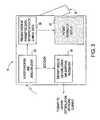
- FIG. 3is an upper level pictorial representation of a defibrillator/monitor in an embodiment of the present teachings
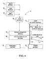
- FIG. 4is a schematic view of a patient module in an embodiment of the present teachings.
- FIG. 4Ais a pictorial representation of a multiple patient module storage and attachment assembly in an embodiment of the present teachings
- FIG. 5is a schematic view of a defibrillator/monitor in an embodiment of the present teachings
- FIG. 6is a perspective view of a pod and pod display according to one embodiment of the teachings.
- FIG. 7is a perspective view of a pod and pod display according to one embodiment of the teachings, showing batteries positioned within;
- FIG. 8is a side view of a pod according to one embodiment of the teachings, showing the position of the connectors and handle;
- FIG. 9is a perspective view of a lead separator according to one embodiment of the teachings.
- FIG. 10is a perspective view of a pod carrying bag according to one embodiment of the teachings.
- FIG. 11is a side view of the pod carrying bag displayed in FIG. 5 in a connected position with a defibrillator;
- FIG. 12is a front view of a pod carrying bag having a shoulder strap in accordance with one embodiment of the teachings
- FIG. 12Ais a front view close-up of a buckle for a pod carrying bag having a should strap as shown in FIG. 12 in an embodiment of the present teachings;
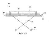
- FIG. 13is a side view of a standard patient gurney
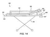
- FIG. 14is side view of a patient gurney adjusted to allow for pod mounting
- FIG. 15is an elevated view of a pod positioned on top of a patient
- FIG. 16is a perspective view of a pod shoulder strap secured to a gurney rail
- FIG. 17is a perspective view of a pod holding tray secured to a gurney.
- FIG. 18is a pictorial representation of a mating assembly having a tethered connector in an embodiment of the present teachings.
- FIG. 19is a pictorial representation of a mating assembly having a tethered connector in an embodiment of the present teachings.
- External defibrillator 10is comprised of two components patient module (pod) 12 and defibrillator/monitor (base) 14 , which communicate patient data (e.g., vital signs) and share common replaceable battery technology.
- Pod 12generally rests within base 14 , generally in the back of base 14 .
- the operatorduring an emergency, has the option of carrying base 14 with pod 12 attached or simply carrying pod 12 to the emergency site. Since pod 12 is smaller and lighter than base 14 , generally it will be easier for the operator to simply carry pod 12 . By carrying pod 12 , the operator is free to carry more ALS equipment and not be slowed by the heavier and more awkward base 14 .
- Pod 12connects to a patient via several leads in order to measure the patient's vital signs.
- Pod 12communicates the patient's vital signs either wirelessly or via an electrical connection to defibrillator monitor 14 .
- the patient data or vital signs collectedmay include 3, 4, and 5 lead ECG readings, 12 lead ECG readings, non-invasive blood pressure (NIBP), pulse oximeter data, capnography data, invasive blood pressure, body temperature, CO 2 levels, and additional patient monitoring functions.
- pod 12may include a small display 82 ( FIG. 4 ) replicating some or all of the information such as waveforms, numerical data, and vital signs being transmitted to base 14 .
- the patient data or vital signsmay be collected with a multitude of leads 11 such as an ECG lead 19 , a non-invasive blood pressure lead 8 , and pulse oximeter lead 6 , extending from patient lead cable port 9 that may include many inputs if multiple lead cables are used.
- Base 14includes a therapy module 56 ( FIG. 3 ) and therapy cables.
- Therapy module 56has the capability to provide therapeutic functions such as pacing, defibrillation, or synchronous cardioversion without attaching another monitor/defibrillator to the patient.
- the therapy cablestypically include patient paddles or electrodes that attach between the patient and base 14 in order to deliver the therapy to the patient. Since pod 12 connects to the patient and transmits vital signs to base 14 , then base 14 need not also have patient monitoring cables.
- Therapy module 56 in base 14may be configurable in either an ALS mode or an AED mode.
- the ALS modeincludes a multi-parameter monitoring capability and all of the defibrillator therapy delivery capability. Additionally base unit 14 may be just an AED.
- pod 12uses replaceable or rechargeable batteries 16 for power and comprises any combination of the following features: 3, 4, and 5 lead ECG inputs 18 , 12 lead ECG inputs 20 , non-invasive blood pressure (NIBP) input 22 , pulse oximeter input 24 , capnography input (not shown), invasive blood pressure input 26 , temperature input 28 , CO 2 input 30 , additional patient monitoring functions, wireless (RF) transceiver 32 to transmit any or all real time patient data to base 14 .
- NIBPnon-invasive blood pressure
- oximeter inputnot shown
- capnography inputnot shown
- invasive blood pressure input 26temperature input
- CO 2 input 30CO 2 input
- Transceiver 32can be a wireless BlueTooth module commercially available from TDK, however, transceiver 32 can be any transceiver such as WiFi (802.11), Wirelesse WAN (CDMA, GSM, GPRS, UTMS, etc.), or a wired Fire-Wire (IEEE 1394) without departing from the spirit of the present teachings.
- pod 12may include a small display 82 ( FIG. 4 ) replicating some or all of the information such as waveforms, numerical data, and vital signs being transmitted to base 14 .
- pod 12includes some means by which it can be attached to base 14 for the purpose of carrying base 14 to an emergency scene as is discussed in P.C.T. Application Serial No. US04/12421. Additionally, pod 12 may have a feature allowing it to be easily secured to a gurney or hospital bed.
- Base 14uses a replaceable or rechargeable battery 50 for power.
- Batteries 16 and 50are generally similar in battery chemistry, electrical, and mechanical features to permit the interchangeability between batteries 16 and 50 .
- Batteries 16 and 50can be a LiIon battery providing 16 volts and 3.8 amps, however, most any type of battery can be used without departing from the spirit of the teachings.
- base 14comprises a display 52 sufficient to show current and historical patient data, a transceiver (similar to transceiver 32 [not shown]) to send acquired patient data onto a receiving station or third party data receiver, a module 56 to synchronize shocks and pacing pulses to the patient's intrinsic rhythm from data acquired by a pod 12 , an error checking and de-multiplexing module 54 receiving and processing data received from pod 12 , and a data interpretation module 58 which analyzes data acquired by pod 12 and makes certain interpretive statements on the patient's cardiac or respiratory condition, displays vital sign trends, and provides additional functions found in ALS monitoring products.
- a transceiversimilar to transceiver 32 [not shown]
- module 56to synchronize shocks and pacing pulses to the patient's intrinsic rhythm from data acquired by a pod 12
- an error checking and de-multiplexing module 54receiving and processing data received from pod 12
- a data interpretation module 58which analyzes data acquired by pod 12 and makes certain interpretive statements on the patient's cardiac or
- pod 12can be powered from a removable/rechargeable battery 60 .
- Power module 62processes the incoming power into appropriate power levels for each of the internal components.
- Power module 62routes the pod's power supply through main power and data bus 64 to system controller module 66 , patient parameter module 68 , and operator interface module 70 .
- pod 12can be used wirelessly, however, it is helpful if pod 12 is directly connected through a tethered cable 46 ( FIGS. 18 and 19 ) or through attachment to a connector to utilize the speed of data bus 64 .
- a pictorial representation of a mating assembly having a tethered connector in an embodiment of the present teachingsis shown.
- a pod similar to 12rests within slot 40 and connects to base-to-pod connector 42 , which allows base 14 and a pod to communicate with each other.
- Base-to-pod connector 42rests freely within connector cavity 44 , which allows connector cable 46 to retractably exit and enter base 14 .
- Tethered cable 46allows a pod to mate with and rest within base 14 or mate with base 14 when not docked within slot 40 . It is sometimes helpful that base 14 communicate with a pod through tethered cable 46 since communications through a direct connection is generally faster.
- base 14is equipped with a USB bus, which provides quick communication of information between a pod and base 14 .
- Base 14is also able to automatically detect when tethered cable 46 is plugged in so direct communications can be established immediately.
- a direct communication between a pod and base 14can be established.
- This automatic establishment of direct communication between a pod and base 14includes when a pod is docked within base 14 and a connection is made between a pod and base 14 through connector 42 .
- Tethered cable 46provides a system for use when the wireless link between pod 12 and base 14 fails for whatever reason or when precise signal synchronization demands a wired connection. Tethered cable 46 also provides the added advantage in that the user cannot lose cable 46 because it is tethered to base 14 . Wireless links can impose a delay in communication between a pod and base 14 longer than may be experienced with a cable.
- system controller module 66controls interaction of all the pod's modules through data bus 64 and interaction with base 14 through a wired connection, such as tethered cable 46 or wireless (e.g., IrDA, RF, etc.) communication link 72 which would be transmitted by transceiver 32 .
- System controller module 66would also control interaction of separate pod's through communication link 71 which could be a direct connector 570 ( FIG. 4A ), or wireless transmitted by transceiver 32 .
- Patient parameter module 68monitors functions such as invasive blood pressure, patient's temperature, and inputs from the pod leads.
- Module 68further collects inputs from EtCO2 module 74 , NIBP module 76 , and SpO2 module 78 through OEM module 80 .
- Patient parameter module 68takes all of these inputs and processes them for display and routes only a limited number of inputs to small LCD display module 82 through operator interface module 70 .
- Operator Interface module 70allows the operator to primarily interact with pod 12 ; however, it is contemplated that operator could use the module 70 to interact with base 14 as well.
- Podscan come in different sizes generally representing the capability of the pod. For example, smaller pod 574 ′ would provide only the basic features for an external defibrillator, while medium pod 574 would provide several additional features.
- pods 574 and 574 ′can be docked together in mounting recess or slot 572 contemporaneously. In one embodiment, pod 574 could be latched within mounting slot 572 communicating with base 571 through connector 573 . Similarly, pod 574 ′ can be placed within mounting slot 572 contemporaneously with pod 574 and latched in a communicating relationship with base 571 through connector 573 ′.
- pods 574 and 574 ′could be placed within mounting slot 572 without the need for two base-to-pod connectors 573 .
- Pod 574 and 574 ′latch together and communicate through connectors 570 .
- both pods 574 and 574 ′are placed within mounting slot 572 and latched in a communicating relationship with base 571 through connector 573 .
- This embodimentnot only limits the amount of connectors needed on base 571 , but also allows the user to choose the amount of functions the pod can perform. For example, if the user simply needed to perform an ECG, then the user could choose to carry small pod 574 ′.
- connectors 573 , 573 ′, and 570could be most any type of connector such as a USB port, an AC power connector, an RS-232 connector or any other type of connector known to those skilled in the art without departing from the spirit of the invention.
- Base 14is powered by a removable/rechargeable battery 84 , which provides power to power module 86 .
- Power module 86processes the incoming power into appropriate powered levels for each of the internal components.
- Power module 86also routes the base's power supply through main power and data bus 90 to interconnect module 92 , system controller module 94 , therapy module 96 , and operator interface module 98 .
- Interconnect module 92is utilized to detect how pod 12 is connected to base 14 (wirelessly, docked, or tethered cable).
- system controller module 94controls all interaction of all of the base's modules through data bus 90 and interaction with pod 12 through wired or wireless connection communication link 72 or through data bus 90 if pod 12 is connected to base 14 .
- Therapy module 96synchronizes shocks and pacing pulses to the patient's intrinsic rhythm from data acquired from pod 12 .
- Module 96administers shocks from voltages via the defibrillation cap 100 and, in turn, administers pacing pulses to a patient.
- Operator interface module 98allows the operator to primarily interact with base 14 ; however, it is contemplated that the operator could use the module 98 to interact with pod 12 as well.
- LCD module 102allows the operator to view a patient's monitored parameters. Finally, the operator has the option to print out patient information on a printer 104 (e.g., a 100 mm strip chart printer).
- the podis a detachable component of the defibrillator. It is generally stored within a receiving portion of the defibrillator but may be detached and carried to the emergency site, where it is used to monitor various medical parameters of the patient.
- the podcommunicates information to the defibrillator either electrically or wirelessly. Typically, electrical communication is used when the pod is stored within the defibrillator and wireless communication is used when the pod is detached from the defibrillator.
- the defibrillator and podWhen communicating electrically, the defibrillator and pod are connected through electrical connections.
- the electrical connectionscomprise one or more leads connecting the defibrillator to the pod.
- the electrical connectionscomprise direct electrical contact between the defibrillator and pod.
- the podmay be stored within the defibrillator in such a way that each of their electrical components is in direct contact with each other. This direct electrical contact can be used for exchanging data or for recharging the pod battery.
- the defibrillator and podcommunicate via a wireless link.
- wireless communicationis used when the pod is detached from the defibrillator.
- wireless communicationcan also be used when the pod is stored within the receiving portion.
- the podtypically includes a display.
- the displaycan be used to display information that medical personnel may need while monitoring and/or delivering therapeutic functions to the patient at the emergency site.
- the displayis primarily used for displaying patient information.
- the displaymay be used to display current and historical patient data.
- pod 811has a housing 810 having a small display 813 with a limited user interface.
- the pod display 813includes an ECG monitor 815 for displaying primary waveform information, a control 817 for activation of the pod 811 , a control 819 , a 12-lead control 821 and a warning signal 823 .
- the control 819is a non-invasive blood pressure (NIBP) control, which allows the medical personnel to initiate a blood pressure reading.
- NIBPnon-invasive blood pressure
- 12-lead control 821allows the medical personnel to initiate a 12-lead monitoring session.
- the warning signal 823serves to warn of events such as a communication failure between the pod and the defibrillator. Additionally, there are one or more status lights 825 located on the pod display 813 .
- the lights 825e.g., preferably Light Emitting Diodes (LEDs), are preferably used as indicators for the pod, involving such parameters concerning the battery, the connection quality, the pod location, etc.
- LEDsLight Emitting Diodes
- pod 827has a pod display 829 including a screen 831 for monitoring various patient parameters, for example monitoring primary waveform information.
- Screen 831also contains a battery status indicator 833 .
- Battery status indicator 833displays the current power level of pod batteries 835 .
- Pod batteries 835are positioned in electrical contact within pod 827 .
- Pod display of FIG. 7also includes a serial port 837 , a control 839 for powering on and off pod 827 , a warning signal 841 , and a speaker 843 .
- Warning signal 841serves to warn of events such as a communication failure between pod 827 and the defibrillator as discussed above.
- Speaker 843sounds an alarm along with warning signal 841 to alert the medical personnel of warning events.
- the leadsshould remain connected to the patient at the emergency site and also while transporting the patient from the emergency site. Any accidental disconnection of the leads may cause a disruption in the monitoring and/or therapeutic processes.
- a side view of a podshowing the position of the connectors and handle is shown.
- the poditself is designed in a manner so if an object accidentally contacts the pod, or if the pod is dropped, the connected leads will be protected.
- a pod 846is shown comprising a main unit 845 , a display 847 , one or more connectors 849 and a carrying handle 851 .
- Connectors 849are located on the top portion of pod 846 and slightly below carrying handle 851 so if an object contacts the pod from the top, the object will make contact with handle 851 before it contacts connectors 849 .
- carrying handle 851will make contact with the ground, thereby giving some protection to connectors 849 located below.
- the leadsare connected to the patient and the pod in an organized manner. For example, anywhere between 1 to 12 or more leads may be connected to the patient and pod and it would be desirable to easily separate and/or untangle the leads.
- the present teachingsalso provides for a lead separator for organizing and separating the patient leads.
- Lead separator 853contains holes or apertures 855 for receiving leads 857 .
- leads 857When leads 857 are secured within holes 855 , lead separator 853 may be slidably moved along the length of leads 857 , as opposed to being clamped in one position. As separator 853 slides along the length of leads 857 , leads 857 are separated in an organized fashion. Separator 853 can have a top portion 851 and bottom portion 854 which snap together to hold leads 857 within apertures 855 .
- a carrying bag 859for easily transporting the pod to and from the emergency site.
- a pod-carrying bag 859is also desirable for protecting the pod, its connectors, and other components from the outside environment.
- the present teachingsalso provides a carrying bag 859 for carrying the pod. Any suitable carrying bag may be used for carrying the pod.
- carrying bag 859includes a pod compartment 861 for receiving a pod and a pod component compartment 863 for receiving components of the pod.
- Pod compartment 861has a cutout portion 865 so the pod may be positioned in pod compartment 861 so certain of the pod's electrical components are openly accessible through cutout portion 865 , such as direct electrical connection 876 between a pod and a base.
- shoulder strap rings 867are secured to opposing sides of pod compartment 861 for receiving a shoulder strap.
- Component compartment 863comprises an expandable portion 869 and a formed shell 871 .
- Expandable portion 869is connected to pod compartment 861 and comprises a plurality of accordion-like folds 873 .
- the accordion-like folds 873are hinged together at a common hinge 875 .
- a formed shell 871is connected to the expandable portion 869 at a point furthest from pod compartment 861 .
- Formed shell 871comprises a durable material and serves to protect the pod components.
- FIG. 11a side view of the pod-carrying bag displayed in FIG. 10 in a connected position with a defibrillator is shown.
- a pod 879 and carrying bag 859may be positioned in electrical contact with a defibrillator 877 .
- Carrying bag 859may be positioned upon defibrillator 877 so the pod's exposed electrical components are in direct contact with electrical components of defibrillator 877 . This direct electrical contact can be used for exchanging data or for recharging the pod battery.
- the carrying bagmay include any number of pouches or compartments for storing the pod and pod components.
- the pouchesmay also be expandable in design.
- the pouchesmay be opened and closed using any suitable mechanism.
- the pouchesmay be opened and closed using zippers, Velcro fasteners, or magnetic fasteners.
- the pouchesmay also be comprised of several different shapes. The shapes can directly correspond to the shape of the pod itself.
- Carrying bag 859may be comprised of any suitable material.
- the bagmay be comprised of a cleanable material that is flexible, yet sturdy material, such as nylon, plastic, fabric, or any other like materials.
- the bagmay be comprised of a more rigid shell.
- a rigid shellis advantageous because it allows for the bag to stand in an upright position rather than sagging or bunching up.
- a rigid materialalso serves to protect the pod and module components within carrying bag 859 .
- a typical pod carrying bag 859will have means for carrying bag 859 .
- carrying bag 859may be carried by use of a shoulder strap or by use of padded handgrips.
- a shoulder strapis used for carrying bag 859 .
- a shoulder strapmay also be attached directly to pod 879 itself, without the use of a carrying bag 859 .
- the shoulder strapsmay be attached to the carrying bag 859 in any suitable manner.
- the shoulder strapsmay be attached to carrying bag 859 through the use of shoulder strap rings.
- reinforced double stitching and/or reinforcing patchesmay be used to attach the shoulder strap to the fabric of carrying bag 859 .
- the shoulder strapmay be an adjustable strap, so that the user can adjust the strap for a best fit.
- a shoulder strap 881is provided including two straps 883 attached to the main body of the carrying bag and each having an end 885 with corresponding fasteners 887 secured thereto. It should also be apparent these two straps 883 could be attached to the pod itself, rather than to the carrying bag.
- Fasteners 887are used to secure the ends 885 of two straps 883 together, forming a single, connected shoulder strap. Any suitable fastening feature can be used to secure the ends of two straps 883 together.
- fasteners 887include quick release buckles.
- a typical gurney 889includes a mattress 891 resting atop and/or fastened to a supporting surface 893 .
- Supporting surface 893is generally mounted atop an adjustable frame 895 .
- Wheels 897are typically provided on adjustable frame 895 to allow gurney 889 to be pushed or pulled along the ground.
- Running between corresponding corners of a front portion 899 and a rear portion 901 of the gurney 889are two side rails 903 (only one is visibly shown), typically mounted atop the supporting surface 893 .
- the gurney 889is adjustable as illustrated in FIG. 14 .
- the part of the supporting surface 893 on the front portion 899 of the gurney 889preferably can be raised or lowered.
- the patient respiratory regionis subsequently elevated, making monitoring therefrom easier to set up and making treatment thereto easier to administer.
- a pod 904can be operatively coupled below the raised portion of the supporting surface 893
- a pod 904 ′can be operatively coupled above the rigid portion of the supporting surface 893
- a pod 904 ′′can be operatively coupled below the rigid portion of the supporting surface 893 .
- Such couplingis preferably provided through the use of appropriate brackets (not shown) which secure the pod to the gurney 899 in these various positions.
- the podcould likewise be coupled to the rear portion 901 of the gurney 899 when applicable. By being located in any of these positions, the pod is made more accessible for the paramedic (i.e., easier to view and make changes) during monitoring or treatment of the patient.
- the podcan be positioned alongside the patient on the gurney mattress. In other embodiments, the pod can be placed on the patient himself.
- FIG. 15shows a pod 905 placed on a patient 907 .
- Pod 905includes two side flaps 909 attached to opposing sides of pod 905 .
- Side flaps 909each include an internal pouch 911 for carrying components of pod 905 .
- each side flap 909may be folded over the top of pod 905 so the side flaps 909 overlap one another and so the internal pouches 911 are not visible.
- the overlapped side flaps 909may be held together in overlapped position via Velcro strips, snaps, or any other attachment mechanism.
- one side flapmay be longer than the other side flap so it can easily overlap the other side flap.
- pod 905When it is desired to position pod 905 on patient 907 , two side flaps 909 are separated and folded downward over the body of patient 907 in a manner as displayed in FIG. 15 . When side flaps 909 are in this folded downward position, pod 905 is stabilized on patient 907 and inner pouches 911 are visible.
- pod 905While it is perfectly suitable to place pod 905 on top of patient 907 , it is often desirable (and sometimes necessary) to position pod 905 in proximity to patient 907 but not on top of or along with patient 907 on the gurney mattress, as mentioned above.
- many ambulance gurneysare relatively compact so they may fit within an ambulance or transport helicopter and allow sufficient room for medical personnel to attend to patient 907 during transport. As a result, there is often not enough room for pod 905 to be placed on the gurney mattress.
- the podmay also be positioned about one of the rails of the gurney.
- a shoulder strapsecures the pod or pod-carrying bag to a gurney rail.
- a holding trayis provided on a gurney rail for holding the pod.
- a shoulder strap 913is provided for securing a pod or pod carrying bag to a gurney rail 915 .
- shoulder strap 913includes two straps 917 attached to the main body of the carrying bag or pod and each having an end 919 with corresponding fasteners 921 , e.g., quick release buckles secured to each end.
- the paramediccan strap wrap the unconnected straps 917 around a gurney rail 915 and connect them together via the fasteners 921 .
- a holding tray 923is provided for securing pod 925 and/or pod carrying bag to a gurney 927 in methods already mentioned or similar methods.
- Pod holding tray 923typically includes a tray having dimensions slightly larger than the dimensions of pod 925 and/or pod carrying bag. Any dimensions can be used so long as pod 925 and/or pod-carrying bag is comfortably received within tray 923 .
- pod holding tray 923is secured to a foot rail 929 of the gurney.
- holding tray 923may also be secured in any suitable position about a gurney, as mentioned above.
- holding tray 923can be secured to any of the gurney rails.
- tray 923can be secured in a position above or beneath the supporting surface of the gurney.
- the holding trayis detachably secured to a gurney so a paramedic may attach tray 923 to a gurney when needed.
- the trayis permanently secured to a gurney so no attachment/detachment of the tray is needed.
- Holding tray 923can also include support straps for firmly gripping pod 925 and/or pod carrying bag within tray 923 .
- Tray 923may also be provided with one or more bumper pads around its edges to protect the patient and medical staff from injury if the tray is accidentally bumped into.
Landscapes
- Health & Medical Sciences (AREA)
- Cardiology (AREA)
- Heart & Thoracic Surgery (AREA)
- Engineering & Computer Science (AREA)
- Biomedical Technology (AREA)
- Nuclear Medicine, Radiotherapy & Molecular Imaging (AREA)
- Radiology & Medical Imaging (AREA)
- Life Sciences & Earth Sciences (AREA)
- Animal Behavior & Ethology (AREA)
- General Health & Medical Sciences (AREA)
- Public Health (AREA)
- Veterinary Medicine (AREA)
- Electrotherapy Devices (AREA)
Abstract
Description
Claims (12)
Priority Applications (2)
| Application Number | Priority Date | Filing Date | Title |
|---|---|---|---|
| US14/069,021US10413742B2 (en) | 2008-03-05 | 2013-10-31 | Defibrillator patient monitoring pod |
| US16/572,120US20200016421A1 (en) | 2003-12-17 | 2019-09-16 | Defibrillator patient monitoring pod |
Applications Claiming Priority (2)
| Application Number | Priority Date | Filing Date | Title |
|---|---|---|---|
| US58317608A | 2008-03-05 | 2008-03-05 | |
| US14/069,021US10413742B2 (en) | 2008-03-05 | 2013-10-31 | Defibrillator patient monitoring pod |
Related Parent Applications (3)
| Application Number | Title | Priority Date | Filing Date |
|---|---|---|---|
| US10/583,176DivisionUS8600491B2 (en) | 2003-12-17 | 2004-12-17 | Defibrillator patient monitoring pod |
| PCT/US2004/042792DivisionWO2005058413A2 (en) | 2003-12-17 | 2004-12-17 | Defibrillator patient monitoring pod |
| US58317608ADivision | 2003-12-17 | 2008-03-05 |
Related Child Applications (1)
| Application Number | Title | Priority Date | Filing Date |
|---|---|---|---|
| US16/572,120ContinuationUS20200016421A1 (en) | 2003-12-17 | 2019-09-16 | Defibrillator patient monitoring pod |
Publications (2)
| Publication Number | Publication Date |
|---|---|
| US20140142647A1 US20140142647A1 (en) | 2014-05-22 |
| US10413742B2true US10413742B2 (en) | 2019-09-17 |
Family
ID=50728669
Family Applications (2)
| Application Number | Title | Priority Date | Filing Date |
|---|---|---|---|
| US14/069,021Active2029-03-09US10413742B2 (en) | 2003-12-17 | 2013-10-31 | Defibrillator patient monitoring pod |
| US16/572,120AbandonedUS20200016421A1 (en) | 2003-12-17 | 2019-09-16 | Defibrillator patient monitoring pod |
Family Applications After (1)
| Application Number | Title | Priority Date | Filing Date |
|---|---|---|---|
| US16/572,120AbandonedUS20200016421A1 (en) | 2003-12-17 | 2019-09-16 | Defibrillator patient monitoring pod |
Country Status (1)
| Country | Link |
|---|---|
| US (2) | US10413742B2 (en) |
Cited By (1)
| Publication number | Priority date | Publication date | Assignee | Title |
|---|---|---|---|---|
| US12102590B2 (en) | 2020-03-30 | 2024-10-01 | Zoll Medical Corporation | Medical device system and hardware for sensor data acquisition |
Families Citing this family (3)
| Publication number | Priority date | Publication date | Assignee | Title |
|---|---|---|---|---|
| JP6843049B2 (en)* | 2014-12-30 | 2021-03-17 | コーニンクレッカ フィリップス エヌ ヴェKoninklijke Philips N.V. | Charging modular medical devices |
| US11490855B2 (en) | 2019-12-27 | 2022-11-08 | Physio-Control, LLC | Methods and systems for monitoring and delivering therapy to a patient including a detachable adaptor for a monitor module |
| EP4221826A4 (en) | 2020-09-30 | 2024-10-30 | Zoll Medical Corporation | REMOTE MONITORING DEVICES AND RELATED METHODS AND SYSTEMS FOR LISTENING TO AUDIBLE AED SIGNALS |
Citations (121)
| Publication number | Priority date | Publication date | Assignee | Title |
|---|---|---|---|---|
| US3724455A (en) | 1970-06-02 | 1973-04-03 | P Unger | Cardiac warning device |
| US3865101A (en) | 1974-05-01 | 1975-02-11 | Datascope Corp | Portable and separable heart monitor and heart defibrillator apparatus |
| US4096856A (en) | 1976-09-03 | 1978-06-27 | Physio-Control Corporation | Portable electronic physiological instrument having separable first and second components, and improved mechanical connector therefor |
| US4635639A (en) | 1985-01-08 | 1987-01-13 | Physio-Control Corporation | Modular physiological instrument |
| US4916439A (en) | 1987-01-05 | 1990-04-10 | Eac Technologies Corp. | Remote display arrangement for appliances |
| US5012411A (en) | 1985-07-23 | 1991-04-30 | Charles J. Policastro | Apparatus for monitoring, storing and transmitting detected physiological information |
| US5078134A (en) | 1988-04-25 | 1992-01-07 | Lifecor, Inc. | Portable device for sensing cardiac function and automatically delivering electrical therapy |
| US5105821A (en) | 1989-07-18 | 1992-04-21 | Reyes Rey S | Interface cable for connecting bedside electrocardiograph monitor to portable defibrillator/electrocardiograph machine |
| US5311449A (en) | 1991-03-25 | 1994-05-10 | Angeion Corporation | Sterilizable hand-held programmer/interrogator |
| US5321837A (en) | 1991-10-11 | 1994-06-14 | International Business Machines Corporation | Event handling mechanism having a process and an action association process |
| US5419336A (en) | 1990-05-10 | 1995-05-30 | Margison; Stephen | Heart beat monitoring |
| US5470343A (en) | 1994-06-10 | 1995-11-28 | Zmd Corporation | Detachable power supply for supplying external power to a portable defibrillator |
| US5549659A (en) | 1994-11-04 | 1996-08-27 | Physio-Control Corporation | Communication interface for transmitting and receiving serial data between medical instruments |
| US5549115A (en) | 1994-09-28 | 1996-08-27 | Heartstream, Inc. | Method and apparatus for gathering event data using a removable data storage medium and clock |
| US5565759A (en) | 1994-12-15 | 1996-10-15 | Intel Corporation | Smart battery providing battery life and recharge time prediction |
| US5593426A (en) | 1994-12-07 | 1997-01-14 | Heartstream, Inc. | Defibrillator system using multiple external defibrillators and a communications network |
| EP0801959A2 (en) | 1996-04-15 | 1997-10-22 | Physio-Control Corporation | Common therapy/data port for a portable defibrillator |
| US5680863A (en) | 1996-05-30 | 1997-10-28 | Acuson Corporation | Flexible ultrasonic transducers and related systems |
| US5683423A (en) | 1996-03-14 | 1997-11-04 | Hewlett-Packard Company | Defibrillator and method for storing selected segments of audio data |
| US5685314A (en) | 1992-12-11 | 1997-11-11 | Siemens Medical Systems, Inc. | Auxiliary docking station for a patient monitoring system |
| US5715823A (en) | 1996-02-27 | 1998-02-10 | Atlantis Diagnostics International, L.L.C. | Ultrasonic diagnostic imaging system with universal access to diagnostic information and images |
| US5724985A (en) | 1995-08-02 | 1998-03-10 | Pacesetter, Inc. | User interface for an implantable medical device using an integrated digitizer display screen |
| US5749902A (en) | 1996-05-22 | 1998-05-12 | Survivalink Corporation | Recorded data correction method and apparatus for isolated clock systems |
| US5787155A (en) | 1994-11-04 | 1998-07-28 | Physio-Control Corporation | Priority line switching system |
| US5814089A (en) | 1996-12-18 | 1998-09-29 | Medtronic, Inc. | Leadless multisite implantable stimulus and diagnostic system |
| US5836993A (en) | 1996-05-16 | 1998-11-17 | Heartstream, Inc. | Electrotherapy device control system and method |
| US5857967A (en) | 1997-07-09 | 1999-01-12 | Hewlett-Packard Company | Universally accessible healthcare devices with on the fly generation of HTML files |
| US5879374A (en) | 1993-05-18 | 1999-03-09 | Heartstream, Inc. | External defibrillator with automatic self-testing prior to use |
| EP0923961A1 (en) | 1997-12-22 | 1999-06-23 | Lifecor, Inc. | Battery management apparatus for portable electronic devices |
| US5921938A (en) | 1997-10-09 | 1999-07-13 | Physio-Control Manufacturing Corporation | System and method for adjusting time associated with medical event data |
| US5950632A (en) | 1997-03-03 | 1999-09-14 | Motorola, Inc. | Medical communication apparatus, system, and method |
| USD414869S (en) | 1998-06-03 | 1999-10-05 | Medtronic Physio-Control Manufacturing Corp. | Defibrillator with retractable hooks |
| US5999493A (en) | 1996-05-13 | 1999-12-07 | Survivalink Corporation | Synchronization method and apparatus for isolated clock system |
| US6024699A (en) | 1998-03-13 | 2000-02-15 | Healthware Corporation | Systems, methods and computer program products for monitoring, diagnosing and treating medical conditions of remotely located patients |
| US6041257A (en) | 1994-09-28 | 2000-03-21 | Heartstream | Method of using a measuring instrument and data gathering system |
| US6057758A (en) | 1998-05-20 | 2000-05-02 | Hewlett-Packard Company | Handheld clinical terminal |
| US6102856A (en) | 1997-02-12 | 2000-08-15 | Groff; Clarence P | Wearable vital sign monitoring system |
| US6111505A (en) | 1996-07-03 | 2000-08-29 | Fred N. Gratzon | Security system |
| US6134468A (en) | 1996-12-31 | 2000-10-17 | Agilent Technologies, Inc. | Method and apparatus for reducing defibrillation energy |
| US6141584A (en) | 1998-09-30 | 2000-10-31 | Agilent Technologies, Inc. | Defibrillator with wireless communications |
| US6144922A (en) | 1997-10-31 | 2000-11-07 | Mercury Diagnostics, Incorporated | Analyte concentration information collection and communication system |
| US6150951A (en) | 1997-12-22 | 2000-11-21 | Hewlett-Packard | Medical telemetry system with wireless and physical communication channels |
| WO2000070889A1 (en) | 1999-05-14 | 2000-11-23 | Medtronic Physio-Control Manufacturing Corp. | Method and apparatus for remote wireless communication with a medical device |
| US6157313A (en) | 1998-02-19 | 2000-12-05 | Motorola | Method and apparatus utilizing a multifunction remote appliance sensor |
| US6183417B1 (en) | 1992-12-11 | 2001-02-06 | Siemens Medical Systems, Inc. | Docking station for a patient monitoring system |
| US6188407B1 (en) | 1998-03-04 | 2001-02-13 | Critikon Company, Llc | Reconfigurable user interface for modular patient monitor |
| US6201992B1 (en) | 1999-04-01 | 2001-03-13 | Agilent Technologies, Inc. | Defibrillator interface capable of generating video images |
| US6223077B1 (en) | 1998-01-26 | 2001-04-24 | Physio-Control Manufacturing Corporation | Automatic power switching in a defibrillator |
| US6275737B1 (en) | 1998-10-14 | 2001-08-14 | Advanced Bionics Corporation | Transcutaneous transmission pouch |
| WO2001066182A1 (en) | 2000-03-09 | 2001-09-13 | Cardiac Science, Inc. | An automatic defibrillator module for integration with standard patient monitoring equipment |
| US6301501B1 (en) | 1999-06-17 | 2001-10-09 | Robert D. Kolder | Protective defibrillator storage device with alarm signal |
| US6301502B1 (en) | 1997-03-07 | 2001-10-09 | Cardiac Science Inc. | Defibrillation system |
| US20010041920A1 (en) | 2000-01-21 | 2001-11-15 | Starkweather Timothy J. | Ambulatory medical apparatus and method having telemetry modifiable control software |
| US6321113B1 (en) | 1998-03-31 | 2001-11-20 | Survivalink Corporation | Automatic external defibrillator first responder and clinical data outcome management system |
| US6323782B1 (en) | 1999-06-21 | 2001-11-27 | Freight Locker, Inc. | Unattended item delivery system |
| US6334070B1 (en) | 1998-11-20 | 2001-12-25 | Medtronic Physio-Control Manufacturing Corp. | Visual and aural user interface for an automated external defibrillator |
| US6336900B1 (en) | 1999-04-12 | 2002-01-08 | Agilent Technologies, Inc. | Home hub for reporting patient health parameters |
| USD455492S1 (en) | 2001-05-02 | 2002-04-09 | Medtronic Physio-Control Manufacturing Corp. | Portable external defibrillator |
| US6370428B1 (en) | 1999-08-11 | 2002-04-09 | David E. Snyder | Method for configuring a defibrillator |
| US6377223B1 (en)* | 1999-11-11 | 2002-04-23 | Ge Medical Systems Information Technologies, Inc. | Portable patient monitor with antenna integrated into handle |
| US6402691B1 (en) | 1999-09-21 | 2002-06-11 | Herschel Q. Peddicord | In-home patient monitoring system |
| US6422669B1 (en)* | 1998-11-09 | 2002-07-23 | Koninklijke Philips Electronics N.V. | Carrying case for defibrillator |
| US20020103508A1 (en) | 2001-01-29 | 2002-08-01 | Prabodh Mathur | Remotely operated defibrillator |
| EP1228782A1 (en) | 2001-01-31 | 2002-08-07 | St. Jude Medical AB | Medical communication system |
| US6434429B1 (en) | 1999-06-25 | 2002-08-13 | Biotronik Mess- Und Therapiegeraete Gmbh & Co. Ingenieurbuero Berlin | Implant with close and long-range telemetry |
| US20020116034A1 (en) | 2001-02-20 | 2002-08-22 | Victor Miller | Controllable, wearable MRI-compatible pacemaker with power carrying photonic catheter and VOO functionality |
| US20020116033A1 (en) | 2001-02-20 | 2002-08-22 | Wilson Greatbatch | Controllable, wearable MRI-compatible cardiac pacemaker with pulse carrying photonic catheter and VOO functionality |
| US20020116028A1 (en) | 2001-02-20 | 2002-08-22 | Wilson Greatbatch | MRI-compatible pacemaker with pulse carrying photonic catheter providing VOO functionality |
| US6441747B1 (en) | 2000-04-18 | 2002-08-27 | Motorola, Inc. | Wireless system protocol for telemetry monitoring |
| US20020123673A1 (en) | 1999-12-17 | 2002-09-05 | Webb James D. | Method and apparatus for remotely programming implantable medical devices |
| US20020138103A1 (en)* | 2001-03-20 | 2002-09-26 | Mulhauser Daniel F. | Defibrillator using low impedance high capacitance double layer capacitor |
| EP1250944A2 (en) | 2001-04-16 | 2002-10-23 | GE Medical Systems Information Technologies, Inc. | Portable patient monitor with defibrillator/pacemaker interface and battery power management |
| US20020177793A1 (en)* | 2001-05-25 | 2002-11-28 | Sherman Darren R. | CPR assist device with pressure bladder feedback |
| US6493581B2 (en) | 2000-12-28 | 2002-12-10 | Koninklijke Philips Electronics N.V. | System and method for rapid recruitment of widely distributed easily operated automatic external defibrillators |
| WO2003009895A1 (en) | 2001-07-20 | 2003-02-06 | Koninklijke Philips Electronics N.V. | Modular medical device and automated external defibrillator |
| US20030025602A1 (en) | 2001-07-31 | 2003-02-06 | Medtronic Physio-Control Manufacturing Corp | Method and system for locating a portable medical device |
| US6524241B2 (en) | 2000-02-14 | 2003-02-25 | First Opinion Corporation | Automated diagnostic system and method including multiple diagnostic modes |
| US20030045905A1 (en) | 2001-08-31 | 2003-03-06 | Daynes John C. | Hard paddle for an external defibrillator |
| US20030050538A1 (en) | 2001-05-29 | 2003-03-13 | Morteza Naghavi | System and method for medical observation system located away from a hospital |
| US20030058097A1 (en) | 2001-09-24 | 2003-03-27 | Medtronic Physio-Control Manufacturing Corp. | System, method and apparatus for sensing and communicating status information from a portable medical device |
| US20030097160A1 (en) | 2001-11-19 | 2003-05-22 | Caby Glen D. | Internal medical device communication bus |
| US20030109904A1 (en) | 2001-12-10 | 2003-06-12 | Medtronic Physio-Control Manufacturing Corp. | Enhanced interface for a medical device and a terminal |
| US6594634B1 (en) | 1998-09-14 | 2003-07-15 | Medtronic Physio-Control Corp. | Method and apparatus for reporting emergency incidents |
| US20030167074A1 (en) | 2002-03-04 | 2003-09-04 | Rodney Merry | Docking station for defibrillator |
| US20030212311A1 (en) | 2002-05-07 | 2003-11-13 | Medtronic Physio-Control Manufacturing Corp. | Therapy-delivering portable medical device capable of triggering and communicating with an alarm system |
| US6668192B1 (en) | 1997-04-08 | 2003-12-23 | Cardiac Science, Inc. | Automated external defibrilator with the ability to store rescue information |
| US20040049233A1 (en) | 2002-09-11 | 2004-03-11 | Edwards D. Craig | Medical device status information system |
| US20040096808A1 (en)* | 2002-11-20 | 2004-05-20 | Price Amy J. | Communication assist device |
| US20040102167A1 (en) | 2002-11-26 | 2004-05-27 | Samsung Electronics Co., Ltd. | Method for displaying received signal strength bars in wireless terminal device |
| US20040111122A1 (en) | 2000-11-13 | 2004-06-10 | Medtronic Physio-Control Manufacturing Corp. | Defibrillator with a multiple-mode interface |
| US20040122476A1 (en)* | 2002-12-24 | 2004-06-24 | Peter Wung | Emergency medical devices with multiple displays |
| US6771172B1 (en) | 1999-11-11 | 2004-08-03 | General Electric Company | Portable patient monitor with alarm light integrated into handle |
| US20040162586A1 (en)* | 2003-02-18 | 2004-08-19 | Covey Kevin K. | Defibrillator electrodes with identification tags |
| US20040204743A1 (en) | 2003-01-14 | 2004-10-14 | Mcgrath Thomas J. | Remotely operating external medical devices |
| WO2004093979A1 (en) | 2003-04-22 | 2004-11-04 | Medtronic Physio-Control Corp. | Defibrillator/monitor system having a pod with leads capable of wirelessly communicating |
| US20050075671A1 (en)* | 2003-10-02 | 2005-04-07 | Vaisnys Gintaras A. | External defibrillator enclosure with accessory storage slot |
| US20050124866A1 (en) | 2003-11-12 | 2005-06-09 | Joseph Elaz | Healthcare processing device and display system |
| WO2005058416A1 (en) | 2003-12-17 | 2005-06-30 | Medtronic Physio-Control Corp. | An external defibrillator with power and battery sharing capabilities with a pod |
| US6978181B1 (en) | 2002-05-24 | 2005-12-20 | Pacesetter, Inc. | Inter-programmer communication among programmers of implantable medical devices |
| US20050288571A1 (en) | 2002-08-20 | 2005-12-29 | Welch Allyn, Inc. | Mobile medical workstation |
| US20060069326A1 (en)* | 2004-09-24 | 2006-03-30 | Roger Lee Heath | Resuscitation and life support system, method and apparatus |
| US20060142808A1 (en)* | 2003-04-22 | 2006-06-29 | Christopher Pearce | Defibrillator/monitor system having a pod with leads capable of wirelessly communicating |
| US20060149323A1 (en) | 2004-12-30 | 2006-07-06 | Merry Randy L | Medical device information system |
| US20060149321A1 (en) | 2004-12-30 | 2006-07-06 | Merry Randy L | Medical device information system |
| US20060173498A1 (en) | 2005-01-31 | 2006-08-03 | Isabelle Banville | Communication between an external defibrillator and an implantable medical device |
| US7110825B2 (en) | 2003-03-03 | 2006-09-19 | Lumenis Ltd. | Method, a system, and a device for detecting and for reducing energy leakage from an energy treatment devices |
| US20070213775A1 (en) | 2005-07-19 | 2007-09-13 | Koninklijke Philips Electronics N.V. | External Defibrillator With Pre-Cpr-Ecg Based Defibrillating Shock |
| US20080077185A1 (en) | 2003-12-17 | 2008-03-27 | Christopher Pearce | Defibrillator/Monitor System Having a Pod with Leads Capable of Wirelessly Communicating |
| US20080221930A1 (en)* | 2007-03-09 | 2008-09-11 | Spacelabs Medical, Inc. | Health data collection tool |
| US20080221397A1 (en) | 2003-12-17 | 2008-09-11 | Mcmahon Michael D | Defibrillator Patient Monitoring Pod |
| US20080287859A1 (en)* | 2007-05-17 | 2008-11-20 | Miller Larry J | Method and Apparatus to Monitor Patients and Treat with Intraosseous Fluids |
| US7570994B2 (en) | 2003-04-25 | 2009-08-04 | Medtronic Physio-Control Corp. | Apparatus and method for maintaining a defibrillator battery charge and optionally communicating |
| US8040246B2 (en) | 2007-12-04 | 2011-10-18 | Avaya Inc. | Systems and methods for facilitating a first response mission at an incident scene |
| USD649644S1 (en) | 2010-07-01 | 2011-11-29 | Shenzhen Mindray Bio-Medical Electronics Co., Ltd. | Defibrillator |
| US8154246B1 (en) | 2009-01-30 | 2012-04-10 | Comverge, Inc. | Method and system for charging of electric vehicles according to user defined prices and price off-sets |
| USD658296S1 (en) | 2009-12-28 | 2012-04-24 | Koninklijke Philips Electronics N.V. | Defibrillator |
| WO2013056194A1 (en) | 2011-10-14 | 2013-04-18 | Zoll Medical Corporation | Automated delivery of medical device support software |
| USD693006S1 (en) | 2010-11-15 | 2013-11-05 | Nihon Kohden Corporation | Defibrillator |
| US8594784B2 (en) | 2009-02-20 | 2013-11-26 | Babric Life Science Innovations, Llc. | Kits and methods for retrofitting and adapting common notebooks, laptop computers, and tablets, to enable each to be used as an automated external defibrillator (AED), and as a manual defibrillator |
| US9168386B2 (en) | 2009-02-20 | 2015-10-27 | Comptolife, Llc | Adaptation of the common notebook, laptop computer, netbook and tablet PC computer to enable each to be used as an automated external defibrillator (AED) to treat victims of sudden cardiac arrest |
| US9289621B2 (en) | 2012-05-08 | 2016-03-22 | Physio-Control, Inc. | Defibrillator network system |
Family Cites Families (1)
| Publication number | Priority date | Publication date | Assignee | Title |
|---|---|---|---|---|
| US20040009680A1 (en)* | 2002-07-10 | 2004-01-15 | Applied Materials, Inc. | Seedless method of forming a silicon germanium layer on a gate dielectric layer |
- 2013
- 2013-10-31USUS14/069,021patent/US10413742B2/enactiveActive
- 2019
- 2019-09-16USUS16/572,120patent/US20200016421A1/ennot_activeAbandoned
Patent Citations (171)
| Publication number | Priority date | Publication date | Assignee | Title |
|---|---|---|---|---|
| US3724455A (en) | 1970-06-02 | 1973-04-03 | P Unger | Cardiac warning device |
| US3865101A (en) | 1974-05-01 | 1975-02-11 | Datascope Corp | Portable and separable heart monitor and heart defibrillator apparatus |
| US4096856A (en) | 1976-09-03 | 1978-06-27 | Physio-Control Corporation | Portable electronic physiological instrument having separable first and second components, and improved mechanical connector therefor |
| US4635639A (en) | 1985-01-08 | 1987-01-13 | Physio-Control Corporation | Modular physiological instrument |
| US5012411A (en) | 1985-07-23 | 1991-04-30 | Charles J. Policastro | Apparatus for monitoring, storing and transmitting detected physiological information |
| US4916439A (en) | 1987-01-05 | 1990-04-10 | Eac Technologies Corp. | Remote display arrangement for appliances |
| US5078134A (en) | 1988-04-25 | 1992-01-07 | Lifecor, Inc. | Portable device for sensing cardiac function and automatically delivering electrical therapy |
| US5105821A (en) | 1989-07-18 | 1992-04-21 | Reyes Rey S | Interface cable for connecting bedside electrocardiograph monitor to portable defibrillator/electrocardiograph machine |
| US5419336A (en) | 1990-05-10 | 1995-05-30 | Margison; Stephen | Heart beat monitoring |
| US5311449A (en) | 1991-03-25 | 1994-05-10 | Angeion Corporation | Sterilizable hand-held programmer/interrogator |
| US5321837A (en) | 1991-10-11 | 1994-06-14 | International Business Machines Corporation | Event handling mechanism having a process and an action association process |
| US6183417B1 (en) | 1992-12-11 | 2001-02-06 | Siemens Medical Systems, Inc. | Docking station for a patient monitoring system |
| US5685314A (en) | 1992-12-11 | 1997-11-11 | Siemens Medical Systems, Inc. | Auxiliary docking station for a patient monitoring system |
| US5879374A (en) | 1993-05-18 | 1999-03-09 | Heartstream, Inc. | External defibrillator with automatic self-testing prior to use |
| US5470343A (en) | 1994-06-10 | 1995-11-28 | Zmd Corporation | Detachable power supply for supplying external power to a portable defibrillator |
| US5674252A (en) | 1994-09-28 | 1997-10-07 | Heartstream, Inc. | Quality assurance method for a care delivery system |
| US6047207A (en) | 1994-09-28 | 2000-04-04 | Heartstream, Inc. | Method of using a measuring instrument and data gathering system |
| US5899866A (en) | 1994-09-28 | 1999-05-04 | Heartstream, Inc. | Method and apparatus for recording and replaying time-correlated medical event data |
| US5891049A (en) | 1994-09-28 | 1999-04-06 | Heartstream, Inc | Time and data correlated medical display system |
| US5891046A (en) | 1994-09-28 | 1999-04-06 | Heartstream, Inc. | Method of assembling a time-correlated medical event database |
| US6041257A (en) | 1994-09-28 | 2000-03-21 | Heartstream | Method of using a measuring instrument and data gathering system |
| US5951485A (en) | 1994-09-28 | 1999-09-14 | Heartstream, Inc. | Method and apparatus for recording and replaying time-correlated medical event data |
| US5549115A (en) | 1994-09-28 | 1996-08-27 | Heartstream, Inc. | Method and apparatus for gathering event data using a removable data storage medium and clock |
| US5749913A (en) | 1994-09-28 | 1998-05-12 | Heartstream, Inc. | System and method for collecting and storing electrotherapy data on a detachable memory device |
| US5787155A (en) | 1994-11-04 | 1998-07-28 | Physio-Control Corporation | Priority line switching system |
| US5549659A (en) | 1994-11-04 | 1996-08-27 | Physio-Control Corporation | Communication interface for transmitting and receiving serial data between medical instruments |
| US5782878A (en) | 1994-12-07 | 1998-07-21 | Heartstream, Inc. | External defibrillator with communications network link |
| US5593426A (en) | 1994-12-07 | 1997-01-14 | Heartstream, Inc. | Defibrillator system using multiple external defibrillators and a communications network |
| US5565759A (en) | 1994-12-15 | 1996-10-15 | Intel Corporation | Smart battery providing battery life and recharge time prediction |
| US5724985A (en) | 1995-08-02 | 1998-03-10 | Pacesetter, Inc. | User interface for an implantable medical device using an integrated digitizer display screen |
| US5715823A (en) | 1996-02-27 | 1998-02-10 | Atlantis Diagnostics International, L.L.C. | Ultrasonic diagnostic imaging system with universal access to diagnostic information and images |
| US5683423A (en) | 1996-03-14 | 1997-11-04 | Hewlett-Packard Company | Defibrillator and method for storing selected segments of audio data |
| US5716380A (en)* | 1996-04-15 | 1998-02-10 | Physio-Control Corporation | Common therapy/data port for a portable defibrillator |
| EP0801959A2 (en) | 1996-04-15 | 1997-10-22 | Physio-Control Corporation | Common therapy/data port for a portable defibrillator |
| US5999493A (en) | 1996-05-13 | 1999-12-07 | Survivalink Corporation | Synchronization method and apparatus for isolated clock system |
| US5836993A (en) | 1996-05-16 | 1998-11-17 | Heartstream, Inc. | Electrotherapy device control system and method |
| US5749902A (en) | 1996-05-22 | 1998-05-12 | Survivalink Corporation | Recorded data correction method and apparatus for isolated clock systems |
| US5680863A (en) | 1996-05-30 | 1997-10-28 | Acuson Corporation | Flexible ultrasonic transducers and related systems |
| US6111505A (en) | 1996-07-03 | 2000-08-29 | Fred N. Gratzon | Security system |
| US5814089A (en) | 1996-12-18 | 1998-09-29 | Medtronic, Inc. | Leadless multisite implantable stimulus and diagnostic system |
| US6134468A (en) | 1996-12-31 | 2000-10-17 | Agilent Technologies, Inc. | Method and apparatus for reducing defibrillation energy |
| US6102856A (en) | 1997-02-12 | 2000-08-15 | Groff; Clarence P | Wearable vital sign monitoring system |
| US5950632A (en) | 1997-03-03 | 1999-09-14 | Motorola, Inc. | Medical communication apparatus, system, and method |
| US6301502B1 (en) | 1997-03-07 | 2001-10-09 | Cardiac Science Inc. | Defibrillation system |
| US6304780B1 (en) | 1997-03-07 | 2001-10-16 | Cardiac Science Inc. | External defibrillator system with diagnostic module |
| US6374138B1 (en) | 1997-03-07 | 2002-04-16 | Cardiac Science Inc. | Defibrillation system |
| US6427083B1 (en) | 1997-03-07 | 2002-07-30 | Cardiac Science, Inc. | Defibrillation system |
| US6668192B1 (en) | 1997-04-08 | 2003-12-23 | Cardiac Science, Inc. | Automated external defibrilator with the ability to store rescue information |
| US5857967A (en) | 1997-07-09 | 1999-01-12 | Hewlett-Packard Company | Universally accessible healthcare devices with on the fly generation of HTML files |
| US5921938A (en) | 1997-10-09 | 1999-07-13 | Physio-Control Manufacturing Corporation | System and method for adjusting time associated with medical event data |
| US6144922A (en) | 1997-10-31 | 2000-11-07 | Mercury Diagnostics, Incorporated | Analyte concentration information collection and communication system |
| US6150951A (en) | 1997-12-22 | 2000-11-21 | Hewlett-Packard | Medical telemetry system with wireless and physical communication channels |
| EP0923961A1 (en) | 1997-12-22 | 1999-06-23 | Lifecor, Inc. | Battery management apparatus for portable electronic devices |
| US5929601A (en) | 1997-12-22 | 1999-07-27 | Lifecor, Inc. | Battery management apparatus for portable electronic devices |
| US6223077B1 (en) | 1998-01-26 | 2001-04-24 | Physio-Control Manufacturing Corporation | Automatic power switching in a defibrillator |
| US6157313A (en) | 1998-02-19 | 2000-12-05 | Motorola | Method and apparatus utilizing a multifunction remote appliance sensor |
| US6188407B1 (en) | 1998-03-04 | 2001-02-13 | Critikon Company, Llc | Reconfigurable user interface for modular patient monitor |
| US6024699A (en) | 1998-03-13 | 2000-02-15 | Healthware Corporation | Systems, methods and computer program products for monitoring, diagnosing and treating medical conditions of remotely located patients |
| US6321113B1 (en) | 1998-03-31 | 2001-11-20 | Survivalink Corporation | Automatic external defibrillator first responder and clinical data outcome management system |
| US6057758A (en) | 1998-05-20 | 2000-05-02 | Hewlett-Packard Company | Handheld clinical terminal |
| USD414869S (en) | 1998-06-03 | 1999-10-05 | Medtronic Physio-Control Manufacturing Corp. | Defibrillator with retractable hooks |
| US6594634B1 (en) | 1998-09-14 | 2003-07-15 | Medtronic Physio-Control Corp. | Method and apparatus for reporting emergency incidents |
| US6597948B1 (en) | 1998-09-30 | 2003-07-22 | Koninklijke Philips Electronics N.V. | Defibrillator with wireless communications |
| US6381492B1 (en) | 1998-09-30 | 2002-04-30 | Martin G. Rockwell | Defibrillator with mode changing infrared communications |
| US6141584A (en) | 1998-09-30 | 2000-10-31 | Agilent Technologies, Inc. | Defibrillator with wireless communications |
| US6438417B1 (en) | 1998-09-30 | 2002-08-20 | Koninklijke Philips Electronics N.V. | Defibrillator test system with wireless communications |
| US6405083B1 (en) | 1998-09-30 | 2002-06-11 | Koninklijke Philips Electronics N.V. | Defibrillator with wireless communication of ECG signals |
| US6275737B1 (en) | 1998-10-14 | 2001-08-14 | Advanced Bionics Corporation | Transcutaneous transmission pouch |
| US6422669B1 (en)* | 1998-11-09 | 2002-07-23 | Koninklijke Philips Electronics N.V. | Carrying case for defibrillator |
| US6334070B1 (en) | 1998-11-20 | 2001-12-25 | Medtronic Physio-Control Manufacturing Corp. | Visual and aural user interface for an automated external defibrillator |
| US6201992B1 (en) | 1999-04-01 | 2001-03-13 | Agilent Technologies, Inc. | Defibrillator interface capable of generating video images |
| US6336900B1 (en) | 1999-04-12 | 2002-01-08 | Agilent Technologies, Inc. | Home hub for reporting patient health parameters |
| WO2000070889A1 (en) | 1999-05-14 | 2000-11-23 | Medtronic Physio-Control Manufacturing Corp. | Method and apparatus for remote wireless communication with a medical device |
| US6301501B1 (en) | 1999-06-17 | 2001-10-09 | Robert D. Kolder | Protective defibrillator storage device with alarm signal |
| US6323782B1 (en) | 1999-06-21 | 2001-11-27 | Freight Locker, Inc. | Unattended item delivery system |
| US6434429B1 (en) | 1999-06-25 | 2002-08-13 | Biotronik Mess- Und Therapiegeraete Gmbh & Co. Ingenieurbuero Berlin | Implant with close and long-range telemetry |
| US6370428B1 (en) | 1999-08-11 | 2002-04-09 | David E. Snyder | Method for configuring a defibrillator |
| US6402691B1 (en) | 1999-09-21 | 2002-06-11 | Herschel Q. Peddicord | In-home patient monitoring system |
| US6377223B1 (en)* | 1999-11-11 | 2002-04-23 | Ge Medical Systems Information Technologies, Inc. | Portable patient monitor with antenna integrated into handle |
| US6771172B1 (en) | 1999-11-11 | 2004-08-03 | General Electric Company | Portable patient monitor with alarm light integrated into handle |
| US20020123673A1 (en) | 1999-12-17 | 2002-09-05 | Webb James D. | Method and apparatus for remotely programming implantable medical devices |
| US20010041920A1 (en) | 2000-01-21 | 2001-11-15 | Starkweather Timothy J. | Ambulatory medical apparatus and method having telemetry modifiable control software |
| US6571128B2 (en) | 2000-01-21 | 2003-05-27 | Medtronic Minimed, Inc. | Microprocessor controlled ambulatory medical apparatus with hand held communication device |
| US6524241B2 (en) | 2000-02-14 | 2003-02-25 | First Opinion Corporation | Automated diagnostic system and method including multiple diagnostic modes |
| WO2001066182A1 (en) | 2000-03-09 | 2001-09-13 | Cardiac Science, Inc. | An automatic defibrillator module for integration with standard patient monitoring equipment |
| US7006865B1 (en) | 2000-03-09 | 2006-02-28 | Cardiac Science Inc. | Automatic defibrillator module for integration with standard patient monitoring equipment |
| US6441747B1 (en) | 2000-04-18 | 2002-08-27 | Motorola, Inc. | Wireless system protocol for telemetry monitoring |
| US20040111122A1 (en) | 2000-11-13 | 2004-06-10 | Medtronic Physio-Control Manufacturing Corp. | Defibrillator with a multiple-mode interface |
| US6493581B2 (en) | 2000-12-28 | 2002-12-10 | Koninklijke Philips Electronics N.V. | System and method for rapid recruitment of widely distributed easily operated automatic external defibrillators |
| WO2002060529A2 (en) | 2001-01-29 | 2002-08-08 | Cardiac Science Inc. | A remotely operated defibrillator |
| US20020103508A1 (en) | 2001-01-29 | 2002-08-01 | Prabodh Mathur | Remotely operated defibrillator |
| EP1228782A1 (en) | 2001-01-31 | 2002-08-07 | St. Jude Medical AB | Medical communication system |
| US20020133201A1 (en) | 2001-02-20 | 2002-09-19 | Connelly Patrick R. | Electromagnetic interference immune tissue invasive system |
| US20020147470A1 (en) | 2001-02-20 | 2002-10-10 | Weiner Michael L. | Electromagnetic interference immune tissue invasive system |
| US20020133216A1 (en) | 2001-02-20 | 2002-09-19 | Connelly Patrick R. | Electromagnetic interference immune tissue invasive system |
| US20020133211A1 (en) | 2001-02-20 | 2002-09-19 | Weiner Michael L. | Electromagnetic interference immune tissue invasive system |
| US20020133199A1 (en) | 2001-02-20 | 2002-09-19 | Macdonald Stuart G. | Electromagnetic interference immune tissue invasive system |
| US20020133202A1 (en) | 2001-02-20 | 2002-09-19 | Connelly Patrick R. | Electromagnetic interference immune tissue invasive system |
| US20020138102A1 (en) | 2001-02-20 | 2002-09-26 | Weiner Michael L. | Electromagnetic interference immune tissue invasive system |
| US20020138108A1 (en) | 2001-02-20 | 2002-09-26 | Weiner Michael L. | Electromagnetic interference immune tissue invasive system |
| US20020138113A1 (en) | 2001-02-20 | 2002-09-26 | Connelly Patrick R. | Electromagnetic interference immune tissue invasive system |
| US20020138112A1 (en) | 2001-02-20 | 2002-09-26 | Connelly Patrick R. | Electromagnetic interference immune tissue invasive system |
| US20020116034A1 (en) | 2001-02-20 | 2002-08-22 | Victor Miller | Controllable, wearable MRI-compatible pacemaker with power carrying photonic catheter and VOO functionality |
| US20020138110A1 (en) | 2001-02-20 | 2002-09-26 | Connelly Patrick R. | Electromagnetic interference immune tissue invasive system |
| US20020138124A1 (en) | 2001-02-20 | 2002-09-26 | Helfer Jeffrey L. | Electromagnetic interference immune tissue invasive system |
| US20020138107A1 (en) | 2001-02-20 | 2002-09-26 | Weiner Michael L. | Electromagnetic interference immune tissue invasive system |
| US20020143258A1 (en) | 2001-02-20 | 2002-10-03 | Weiner Michael L. | Electromagnetic interference immune tissue invasive system |
| US20020116033A1 (en) | 2001-02-20 | 2002-08-22 | Wilson Greatbatch | Controllable, wearable MRI-compatible cardiac pacemaker with pulse carrying photonic catheter and VOO functionality |
| US20020116028A1 (en) | 2001-02-20 | 2002-08-22 | Wilson Greatbatch | MRI-compatible pacemaker with pulse carrying photonic catheter providing VOO functionality |
| US20020116029A1 (en) | 2001-02-20 | 2002-08-22 | Victor Miller | MRI-compatible pacemaker with power carrying photonic catheter and isolated pulse generating electronics providing VOO functionality |
| US20020183796A1 (en) | 2001-02-20 | 2002-12-05 | Connelly Patrick R. | Electromagnetic interference immune tissue invasive system |
| US20020133200A1 (en) | 2001-02-20 | 2002-09-19 | Weiner Michael L. | Electromagnetic interference immune tissue invasive system |
| US20020198569A1 (en) | 2001-02-20 | 2002-12-26 | Foster Thomas H. | Electromagnetic interference immune tissue invasive system |
| US20020133208A1 (en) | 2001-02-20 | 2002-09-19 | Connelly Patrick R. | Electromagnetic interference immune tissue invasive system |
| US20020133086A1 (en) | 2001-02-20 | 2002-09-19 | Connelly Patrick R. | Electromagnetic interference immune tissue invasive system |
| US20020128689A1 (en) | 2001-02-20 | 2002-09-12 | Connelly Patrick R. | Electromagnetic interference immune tissue invasive system |
| US20020128691A1 (en) | 2001-02-20 | 2002-09-12 | Connelly Patrick R. | Electromagnetic interference immune tissue invasive system |
| US20020138103A1 (en)* | 2001-03-20 | 2002-09-26 | Mulhauser Daniel F. | Defibrillator using low impedance high capacitance double layer capacitor |
| EP1250944A2 (en) | 2001-04-16 | 2002-10-23 | GE Medical Systems Information Technologies, Inc. | Portable patient monitor with defibrillator/pacemaker interface and battery power management |
| US6591135B2 (en)* | 2001-04-16 | 2003-07-08 | Ge Medical Systems Information Technologies, Inc. | Portable patient monitor with defibrillator/pacemaker interface and battery power management |
| US20030088275A1 (en) | 2001-04-16 | 2003-05-08 | Palmer Michael J. | Portable patient monitor with defibrillator/pacemaker interface and battery power management |
| USD455492S1 (en) | 2001-05-02 | 2002-04-09 | Medtronic Physio-Control Manufacturing Corp. | Portable external defibrillator |
| US20020177793A1 (en)* | 2001-05-25 | 2002-11-28 | Sherman Darren R. | CPR assist device with pressure bladder feedback |
| US20030050538A1 (en) | 2001-05-29 | 2003-03-13 | Morteza Naghavi | System and method for medical observation system located away from a hospital |
| US20030028219A1 (en) | 2001-07-20 | 2003-02-06 | Powers Daniel J. | Modular medical device, base unit and module thereof, and automated external defibrillator (AED), methods for assembling and using the AED |
| WO2003009895A1 (en) | 2001-07-20 | 2003-02-06 | Koninklijke Philips Electronics N.V. | Modular medical device and automated external defibrillator |
| US20030025602A1 (en) | 2001-07-31 | 2003-02-06 | Medtronic Physio-Control Manufacturing Corp | Method and system for locating a portable medical device |
| US20030045905A1 (en) | 2001-08-31 | 2003-03-06 | Daynes John C. | Hard paddle for an external defibrillator |
| US20030058097A1 (en) | 2001-09-24 | 2003-03-27 | Medtronic Physio-Control Manufacturing Corp. | System, method and apparatus for sensing and communicating status information from a portable medical device |
| US20030097160A1 (en) | 2001-11-19 | 2003-05-22 | Caby Glen D. | Internal medical device communication bus |
| US20030109904A1 (en) | 2001-12-10 | 2003-06-12 | Medtronic Physio-Control Manufacturing Corp. | Enhanced interface for a medical device and a terminal |
| US6957102B2 (en) | 2001-12-10 | 2005-10-18 | Medtronic Emergency Response Systems, Inc. | Enhanced interface for a medical device and a terminal |
| US20030167074A1 (en) | 2002-03-04 | 2003-09-04 | Rodney Merry | Docking station for defibrillator |
| US20030212311A1 (en) | 2002-05-07 | 2003-11-13 | Medtronic Physio-Control Manufacturing Corp. | Therapy-delivering portable medical device capable of triggering and communicating with an alarm system |
| US6978181B1 (en) | 2002-05-24 | 2005-12-20 | Pacesetter, Inc. | Inter-programmer communication among programmers of implantable medical devices |
| US20050288571A1 (en) | 2002-08-20 | 2005-12-29 | Welch Allyn, Inc. | Mobile medical workstation |
| US20040049233A1 (en) | 2002-09-11 | 2004-03-11 | Edwards D. Craig | Medical device status information system |
| US20040096808A1 (en)* | 2002-11-20 | 2004-05-20 | Price Amy J. | Communication assist device |
| US20040102167A1 (en) | 2002-11-26 | 2004-05-27 | Samsung Electronics Co., Ltd. | Method for displaying received signal strength bars in wireless terminal device |
| US20040122476A1 (en)* | 2002-12-24 | 2004-06-24 | Peter Wung | Emergency medical devices with multiple displays |
| US20040204743A1 (en) | 2003-01-14 | 2004-10-14 | Mcgrath Thomas J. | Remotely operating external medical devices |
| US20040162586A1 (en)* | 2003-02-18 | 2004-08-19 | Covey Kevin K. | Defibrillator electrodes with identification tags |
| US7110825B2 (en) | 2003-03-03 | 2006-09-19 | Lumenis Ltd. | Method, a system, and a device for detecting and for reducing energy leakage from an energy treatment devices |
| WO2004093979A1 (en) | 2003-04-22 | 2004-11-04 | Medtronic Physio-Control Corp. | Defibrillator/monitor system having a pod with leads capable of wirelessly communicating |
| US20060142808A1 (en)* | 2003-04-22 | 2006-06-29 | Christopher Pearce | Defibrillator/monitor system having a pod with leads capable of wirelessly communicating |
| US7570994B2 (en) | 2003-04-25 | 2009-08-04 | Medtronic Physio-Control Corp. | Apparatus and method for maintaining a defibrillator battery charge and optionally communicating |
| US20050075671A1 (en)* | 2003-10-02 | 2005-04-07 | Vaisnys Gintaras A. | External defibrillator enclosure with accessory storage slot |
| US20050124866A1 (en) | 2003-11-12 | 2005-06-09 | Joseph Elaz | Healthcare processing device and display system |
| WO2005058416A1 (en) | 2003-12-17 | 2005-06-30 | Medtronic Physio-Control Corp. | An external defibrillator with power and battery sharing capabilities with a pod |
| US20080077185A1 (en) | 2003-12-17 | 2008-03-27 | Christopher Pearce | Defibrillator/Monitor System Having a Pod with Leads Capable of Wirelessly Communicating |
| WO2005058413A2 (en) | 2003-12-17 | 2005-06-30 | Medtronic Physio-Control Corp. | Defibrillator patient monitoring pod |
| US20080221397A1 (en) | 2003-12-17 | 2008-09-11 | Mcmahon Michael D | Defibrillator Patient Monitoring Pod |
| US20080183229A1 (en) | 2003-12-17 | 2008-07-31 | Neumiller James S | External Defibrillator With Power and Battery Sharing Capabilities With a Pod |
| US20060069326A1 (en)* | 2004-09-24 | 2006-03-30 | Roger Lee Heath | Resuscitation and life support system, method and apparatus |
| US20060149321A1 (en) | 2004-12-30 | 2006-07-06 | Merry Randy L | Medical device information system |
| US20060149323A1 (en) | 2004-12-30 | 2006-07-06 | Merry Randy L | Medical device information system |
| US20060173498A1 (en) | 2005-01-31 | 2006-08-03 | Isabelle Banville | Communication between an external defibrillator and an implantable medical device |
| US20070213775A1 (en) | 2005-07-19 | 2007-09-13 | Koninklijke Philips Electronics N.V. | External Defibrillator With Pre-Cpr-Ecg Based Defibrillating Shock |
| US20080221930A1 (en)* | 2007-03-09 | 2008-09-11 | Spacelabs Medical, Inc. | Health data collection tool |
| US20080287859A1 (en)* | 2007-05-17 | 2008-11-20 | Miller Larry J | Method and Apparatus to Monitor Patients and Treat with Intraosseous Fluids |
| US8040246B2 (en) | 2007-12-04 | 2011-10-18 | Avaya Inc. | Systems and methods for facilitating a first response mission at an incident scene |
| US8054177B2 (en) | 2007-12-04 | 2011-11-08 | Avaya Inc. | Systems and methods for facilitating a first response mission at an incident scene using patient monitoring |
| US8154246B1 (en) | 2009-01-30 | 2012-04-10 | Comverge, Inc. | Method and system for charging of electric vehicles according to user defined prices and price off-sets |
| US8594784B2 (en) | 2009-02-20 | 2013-11-26 | Babric Life Science Innovations, Llc. | Kits and methods for retrofitting and adapting common notebooks, laptop computers, and tablets, to enable each to be used as an automated external defibrillator (AED), and as a manual defibrillator |
| US9155902B2 (en) | 2009-02-20 | 2015-10-13 | Comptolife, Llc | Pocket kits and methods for retrofitting and adapting common notebook computers, laptop computers, and tablet computers, to enable each to be used as an automated external defibrillator (AED), and as a manual defibrillator |
| US9168386B2 (en) | 2009-02-20 | 2015-10-27 | Comptolife, Llc | Adaptation of the common notebook, laptop computer, netbook and tablet PC computer to enable each to be used as an automated external defibrillator (AED) to treat victims of sudden cardiac arrest |
| USD658296S1 (en) | 2009-12-28 | 2012-04-24 | Koninklijke Philips Electronics N.V. | Defibrillator |
| USD649644S1 (en) | 2010-07-01 | 2011-11-29 | Shenzhen Mindray Bio-Medical Electronics Co., Ltd. | Defibrillator |
| USD693006S1 (en) | 2010-11-15 | 2013-11-05 | Nihon Kohden Corporation | Defibrillator |
| WO2013056194A1 (en) | 2011-10-14 | 2013-04-18 | Zoll Medical Corporation | Automated delivery of medical device support software |
| US9289621B2 (en) | 2012-05-08 | 2016-03-22 | Physio-Control, Inc. | Defibrillator network system |
Non-Patent Citations (221)
| Title |
|---|
| Advisory Action dated Jan. 21, 2016, U.S. Appl. No. 13/836,769, filed Mar. 15, 2013. |
| Advisory Action dated Mar. 31, 2017, U.S. Appl. No. 12/139,359, filed Jun. 13, 2008. |
| Advisory Action, dated May 12, 2015, U.S. Appl. No. 13/690,094, filed Nov. 30, 2012. |
| Advisory Action, dated Oct. 10, 2013, U.S. Appl. No. 10/583,175, filed Nov. 1, 2007. |
| Advisory Action, mailed Jan. 21, 2016, Application No. 13/836,769, filed Mar. 15, 2013. |
| Amendment After Final dated Mar. 31, 2017, U.S. Appl. No. 12/139,359, filed Jun. 13, 2008. |
| Amendment After Notice of Allowance, dated Mar. 16, 2017, U.S. Appl. No. 13/690,075, filed Nov. 30, 2012. |
| Amendment dated Apr. 11, 2018, U.S. Appl. No. 12/139,359, filed Jun. 13, 2008. |
| Amendment dated Apr. 19, 2017, U.S. Appl. No. 12/139,359, filed Jun. 13, 2008. |
| Amendment dated Dec. 14, 2017, U.S. Appl. No. 12/139,359, filed Jun. 13, 2008. |
| Amendment dated Dec. 21, 2017, U.S. Appl. No. 13/690,075, filed Nov. 30, 2012. |
| Amendment dated Jan. 5, 2011, U.S. Appl. No. 12/139,359, filed Jun. 13, 2008. |
| Amendment dated Jul. 31, 2015, U.S. Appl. No. 13/836,769, filed Mar. 15, 2013. |
| Amendment dated Jun. 6, 2016. U.S. Appl. No. 13/836,769, filed Mar. 15, 2013. |
| Amendment dated Mar. 15, 2016, U.S. Appl. No. 12/139,359, filed Jun. 13, 2008. |
| Amendment dated May 26, 2015, U.S. Appl. No. 12/139,359, filed Jun. 13, 2008. |
| Amendment dated May 30, 2006, U.S. Appl. No. 10/378,001, filed Feb. 28, 2003. |
| Amendment dated Sep. 14, 2016, U.S. Appl. No. 12/139,359, filed Jun. 13, 2008. |
| Amendment dated Sep. 29, 2015, U.S. Appl. No. 12/139,359, filed Jun. 13, 2008. |
| Amendment filed Aug. 23, 2018, U.S. Appl. No. 13/836,769, filed Mar. 15, 2013. |
| Amendment filed Mar. 13, 2018, U.S. Appl. No. 15/245,450, filed Aug. 24, 2016. |
| Amendment filed Mar. 19, 2018, U.S. Appl. No. 13/836,769, filed Mar. 15, 2013. |
| Amendment, dated Apr. 20, 2010, U.S. Appl. No. 11/256,275, filed Oct. 21, 2005. |
| Amendment, dated Apr. 3, 2009, U.S. Appl. No. 11/256,275, filed Oct. 21, 2005. |
| Amendment, dated Apr. 5, 2012, U.S. Appl. No. 10/583,176, filed Mar. 5, 2008. |
| Amendment, dated Aug. 22, 2011, U.S. Appl. No. 10/583,176, filed Mar. 5, 2008. |
| Amendment, dated Aug. 23, 2016, U.S. Appl. No. 13/690,031, filed Nov. 30, 2012. |
| Amendment, dated Aug. 25, 2016, U.S. Appl. No. 13/690,031, filed Nov. 30, 2012. |
| Amendment, dated Dec. 18, 2013, U.S. Appl. No. 13/690,094, filed Nov. 30, 2012. |
| Amendment, dated Dec. 20, 2010, U.S. Appl. No. 10/583,209, filed Oct. 18, 2007. |
| Amendment, dated Dec. 31, 2015, U.S. Appl. No. 14/498,735, filed Sep. 26, 2014. |
| Amendment, dated Feb. 11, 2014, U.S. Appl. No. 10/583,175, filed Nov. 1, 2007. |
| Amendment, dated Feb. 18, 2016, U.S. Appl. No. 13/690,094, filed Nov. 30, 2012. |
| Amendment, dated Feb. 28, 2012, U.S. Appl. No. 13/103,783, filed May 9, 2011. |
| Amendment, dated Feb. 5, 2014, U.S. Appl. No. 13/965,667, filed Aug. 13, 2013. |
| Amendment, dated Feb. 5, 2016, U.S. Appl. No. 13/690,094, filed Nov. 30, 2012. |
| Amendment, dated Jan. 13, 2017, U.S. Appl. No. 15/057,468, filed Mar. 1, 2016. |
| Amendment, dated Jan. 19, 2015, U.S. Appl. No. 13/690,094, filed Nov. 30, 2012. |
| Amendment, dated Jan. 26, 2011, U.S. Appl. No. 10/583,209, filed Oct. 18, 2007. |
| Amendment, dated Jan. 27, 2017, U.S. Appl. No. 13/690,075, filed Nov. 30, 2012. |
| Amendment, dated Jan. 4, 2010, U.S. Appl. No. 10/583,175, filed Nov. 1, 2007. |
| Amendment, dated Jan. 6, 2017, U.S. Appl. No. 15/057,468, filed Mar. 1, 2016. |
| Amendment, dated Jul. 11, 2013, U.S. Appl. No. 10/583,176, filed Mar. 5, 2008. |
| Amendment, dated Jul. 13, 2017, U.S. Appl. No. 15/057,468, filed Mar. 1, 2016. |
| Amendment, dated Jul. 29, 2010, U.S. Appl. No. 10/583,175, filed Nov. 1, 2007. |
| Amendment, dated Jul. 8, 2016, U.S. Appl. No. 15/057,468, filed Mar. 1, 2016. |
| Amendment, dated Jun. 14, 2013, U.S. Appl. No. 10/583,175, filed Nov. 1, 2007. |
| Amendment, dated Jun. 15, 2016, U.S. Appl. No. 13/690,075, filed Nov. 30, 2012. |
| Amendment, dated Jun. 16, 2010, U.S. Appl. No. 10/583,209, filed Oct. 18, 2007. |
| Amendment, dated Jun. 2, 2015, U.S. Appl. No. 13/690,094, filed Nov. 30, 2012. |
| Amendment, dated Jun. 6, 2016, U.S. Appl. No. 13/690,056, filed Nov. 30, 2012. |
| Amendment, dated Mar. 15, 2017, U.S. Appl. No. 13/690,056, filed Nov. 30, 2012. |
| Amendment, dated Mar. 23, 2017, U.S. Appl. No. 15/152,248, filed May 11, 2016. |
| Amendment, dated May 11, 2016, U.S. Appl. No. 13/690,031, filed Nov. 30, 2012. |
| Amendment, dated May 12, 2015, U.S. Appl. No. 13/690,094, filed Nov. 30, 2012. |
| Amendment, dated May 25, 2016, U.S. Appl. No. 14/310,841, filed Jun. 20, 2014. |
| Amendment, dated May 9, 2013, U.S. Appl. No. 13/103,783, filed May 9, 2011. |
| Amendment, dated Nov. 21, 2016, U.S. Appl. No. 15/057,468, filed Mar. 1, 2016. |
| Amendment, dated Nov. 28, 2016, U.S. Appl. No. 13/690,056, filed Nov. 30, 2012. |
| Amendment, dated Nov. 3, 2014, U.S. Appl. No. 29/440,594, filed Dec. 21, 2012. |
| Amendment, dated Nov. 3, 2014, U.S. Appl. No. 29/452,640, filed Apr. 19, 2013. |
| Amendment, dated Oct. 1, 2012, U.S. Appl. No. 10/583,176, filed Mar. 5, 2008. |
| Amendment, dated Oct. 1, 2014, U.S. Appl. No. 29/440,594, filed Dec. 21, 2012. |
| Amendment, dated Oct. 1, 2014, U.S. Appl. No. 29/452,640, filed Apr. 19, 2013. |
| Amendment, dated Oct. 14, 2015, U.S. Appl. No. 13/690,094, filed Nov. 30, 2012. |
| Amendment, dated Oct. 28, 2016, U.S. Appl. No. 13/690,056, filed Nov. 30, 2012. |
| Amendment, dated Oct. 31, 2016, U.S. Appl. No. 15/057,468, filed Mar. 1, 2016. |
| Amendment, dated Oct. 5, 2015, U.S. Appl. No. 13/690,031, filed Nov. 30, 2012. |
| Amendment, dated Oct. 5, 2015, U.S. Appl. No. 13/690,056, filed Nov. 30, 2012. |
| Amendment, dated Oct. 5, 2015, U.S. Appl. No. 13/690,075, filed Nov. 30, 2012. |
| Amendment, dated Oct. 8, 2008, U.S. Appl. No. 11/256,275, filed Oct. 21, 2005. |
| Amendment, dated Sep. 27, 2013, U.S. Appl. No. 10/583,175, filed Nov. 1, 2007. |
| Amendment, dated Sep. 27, 2016, U.S. Appl. No. 14/310,841, filed Jun. 20, 2014. |
| Amendment, dated Sep. 9, 2009, U.S. Appl. No. 11/256,275, filed Oct. 21, 2005. |
| Claims of U.S. U.S. Appl. No. 15/057,468 as of Jul. 8, 2016. |
| Communication from the Examining Division dated Aug. 18, 2008, Application No. EP1617896. |
| Communication from the Examining Division dated Jun. 29, 2017, Application No. EP12816583.4. |
| Decision to Grant dated Aug. 6, 2009, Application No. EP1617896. |
| Final Office Action dated Jan. 13, 2016, U.S. Appl. No. 13/690,075, filed Nov. 30, 2012. |
| Final Office Action dated Jan. 14, 2016, U.S. Appl. No. 13/690,056, filed Nov. 30, 2012. |
| Final Office Action dated Jan. 8, 2016, U.S. Appl. No. 13/690,031, filed Nov. 30, 2012. |
| Final Office Action dated Jul. 13, 2018, U.S. Appl. No. 15/245,450, filed Aug. 24, 2016. |
| Final Office Action dated Jun. 15, 2016, U.S. Appl. No. 13/836,769, filed Mar. 15, 2011. |
| Final Office Action dated Mar. 19, 2018, U.S. Appl. No. 13/690,075, filed Nov. 30, 2012. |
| Final Office Action dated Mar. 24, 2014, U.S. Appl. No. 13/690,094, filed Nov. 30, 2012. |
| Final Office Action dated Mar. 3, 2015, U.S. Appl. No. 13/690,094, filed Nov. 30, 2012. |
| Final Office Action dated May 12, 2017, U.S. Appl. No. 15/152,248, filed May 11, 2016. |
| Final Office Action dated Oct. 18, 2016 , U.S. Appl. No. 13/690,075, filed Nov. 30, 2012. |
| Final Office Action dated Oct. 28, 2015, U.S. Appl. No. 13/836,769, filed Mar. 15, 2011. |
| Final Rejection dated Aug. 2, 2006, U.S. Appl. No. 10/378,001, filed Feb. 28, 2003. |
| Final Rejection dated Dec. 15, 2015, U.S. Appl. No. 12/139,359, filed Jun. 13, 2008. |
| Final Rejection dated Jan. 11, 2018, U.S. Appl. No. 12/139,359, filed Jun. 13, 2008. |
| Final Rejection dated Mar. 22, 2011, U.S. Appl. No. 12/139,359, filed Jun. 13, 2008. |
| Final Rejection dated Nov. 23, 2016, U.S. Appl. No. 12/139,359, filed Jun. 13, 2008. |
| Final Rejection, dated Apr. 29, 2010, U.S. Appl. No. 10/583,175, filed Nov. 1, 2007. |
| Final Rejection, dated Feb. 1, 2013, U.S. Appl. No. 13/103,783, filed May 9, 2011. |
| Final Rejection, dated Feb. 28, 2014, U.S. Appl. No. 13/965,667, filed Aug. 13, 2013. |
| Final Rejection, dated Feb. 3, 2010, U.S. Appl. No. 11/256,275, filed Oct. 21, 2005. |
| Final Rejection, dated Jan. 6, 2009, U.S. Appl. No. 11/256,275, filed Oct. 21, 2005. |
| Final Rejection, dated Jul. 29, 2013, U.S. Appl. No. 10/583,175, filed Nov. 1, 2007. |
| Final Rejection, dated Jul. 7, 2016, U.S. Appl. No. 14/310,841, filed Jun. 20, 2014. |
| Final Rejection, dated Nov. 17, 2011, U.S. Appl. No. 10/583,176, filed Mar. 5, 2008. |
| Final Rejection, dated Oct. 19, 2010, U.S. Appl. No. 10/583,209, filed Oct. 18, 2007. |
| International Preliminary Examination Report, dated Nov. 12, 2004, International Application No. PCT/US03/28463, International Filing Date Sep. 11, 2003. |
| International Preliminary Report on Patentability dated Apr. 18, 2016, International Application No. PCT/US15/055095, international filing date Oct. 12, 2015. |
| International Preliminary Report on Patentability dated Nov. 11, 2014, PCT/US2012/071436, dated Apr. 10, 2013. |
| International Preliminary Report on Patentability dated Nov. 11, 2014, PCT/US2012/071448, dated Feb. 8, 2013, 11 pages. |
| International Preliminary Report on Patentability dated Nov. 11, 2014, PCT/US2012/071450, dated May 24, 2013. |
| International Preliminary Report on Patentability dated Nov. 11, 2014, PCT/US2012/071461, dated Apr. 10, 2013, 14 pages. |
| International Preliminary Report on Patentability from International Application No. PCT/US2004/012421, dated Oct. 28, 2005. |
| International Preliminary Report on Patentability from International Application No. PCT/US2004/042376, dated Jun. 20, 2006. |
| International Preliminary Report on Patentability from International Application No. PCT/US2004/042792, dated Jun. 20, 2006. |
| International Search Report & Written Opinion dated Apr. 21, 2016, International Application No. PCT/US15/055095, international filed Oct. 12, 2015. |
| International Search Report and Written Opinion from International Application No. PCT/US2004/012421, dated Sep. 13, 2004. |
| International Search Report and Written Opinion from International Application No. PCT/US2004/042376, dated Mar. 24, 2005. |
| International Search Report and Written Opinion from International Application No. PCT/US2004/042377, dated Jun. 20, 2006. |
| International Search Report and Written Opinion from International Application No. PCT/US2004/042792, dated Jul. 20, 2005. |
| International Search Report and Written Opinion, PCT/US2012/071436, dated Apr. 10, 2013, 13 pages. |
| International Search Report and Written Opinion, PCT/US2012/071448, dated Feb. 8, 2013, 11 pages. |
| International Search Report and Written Opinion, PCT/US2012/071450, dated May 24, 2013, 10 pages. |
| International Search Report and Written Opinion, PCT/US2012/071461, dated Apr. 10, 2013, 14 pages. |
| Non-Final Action, dated Apr. 14, 2016, U.S. Appl. No. 15/057,468, filed Mar. 1, 2016. |
| Non-Final Action, dated Mar. 13, 2017, U.S. Appl. No. 15/057,468, filed Mar. 1, 2016. |
| Non-Final Rejection dated Dec. 27, 2005, U.S. Appl. No. 10/378,001, filed Feb. 28, 2003. |
| Non-Final Rejection dated Jun. 14, 2017, U.S. Appl. No. 12/139,359, filed Jun. 13, 2008. |
| Non-Final Rejection dated Jun. 15, 2016, U.S. Appl. No. 12/139,359, filed Jun. 13, 2008. |
| Non-Final Rejection dated Jun. 29, 2015, U.S. Appl. No. 12/139,359, filed Jun. 13, 2008. |
| Non-Final Rejection dated Oct. 5, 2010, U.S. Appl. No. 12/139,359, filed Jun. 13, 2008. |
| Non-Final Rejection, dated Aug. 18, 2014, U.S. Appl. No. 29/452,640, filed Apr. 19, 2013. |
| Non-Final Rejection, dated Feb. 28, 2013, U.S. Appl. No. 10/583,175, filed Nov. 1, 2007. |
| Non-Final Rejection, dated Feb. 3, 2011, U.S. Appl. No. 11/256,275, filed Oct. 21, 2005. |
| Non-Final Rejection, dated Feb. 8, 2016, U.S. Appl. No. 14/310,841, filed Jun. 20, 2014. |
| Non-Final Rejection, dated Jan. 16, 2013, U.S. Appl. No. 10/583,176, filed Mar. 5, 2008. |
| Non-Final Rejection, dated Jun. 9, 2008, U.S. Appl. No. 11/256,275, filed Oct. 21, 2005. |
| Non-Final Rejection, dated Jun. 9, 2009, U.S. Appl. No. 11/256,275, filed Oct. 21, 2005. |
| Non-Final Rejection, dated Mar. 16, 2010, U.S. Appl. No. 10/583,209, filed Oct. 18, 2007. |
| Non-Final Rejection, dated May 1, 2012, U.S. Appl. No. 10/583,176, filed Mar. 5, 2008. |
| Non-Final Rejection, dated May 20, 2011, U.S. Appl. No. 10/583,176, filed Mar. 5, 2008. |
| Non-Final Rejection, dated Nov. 1, 2016, U.S. Appl. No. 14/310,841, filed Jun. 20, 2014. |
| Non-Final Rejection, dated Nov. 22, 2013, U.S. Appl. No. 10/583,175, filed Nov. 1, 2007. |
| Non-Final Rejection, dated Nov. 28, 2011, U.S. Appl. No. 13/103,783, filed May 9, 2011. |
| Non-Final Rejection, dated Nov. 5, 2013, U.S. Appl. No. 13/965,667, filed Aug. 13, 2013. |
| Non-Final Rejection, dated Oct. 2, 2009, U.S. Appl. No. 10/583,175, filed Nov. 1, 2007. |
| Non-Final Rejection, dated Sep. 15, 2015, U.S. Appl. No. 14/498,735, filed Sep. 26, 2014. |
| Notice of Allowance dated Aug. 15, 2018, U.S. Appl. No. 15/245,450, filed Aug. 24, 2016. |
| Notice of Allowance dated Jan. 19, 2018, U.S. Appl. No. 13/690,056, filed Nov. 30, 2012. |
| Notice of Allowance dated Jan. 31, 2018, U.S. Appl. No. 15/152,248, filed May 11, 2016. |
| Notice of Allowance dated Jul. 13, 2018, U.S. Appl. No. 13/690,075, filed Nov. 30, 2012. |
| Notice of Allowance dated Jul. 13, 2018, U.S. Appl. No. 15/152,248, filed May 11, 2016. |
| Notice of Allowance dated Jun. 14, 2017, U.S. Appl. No. 13/690,056, filed Nov. 30, 2012. |
| Notice of Allowance dated Jun. 21, 2018, U.S. Appl. No. 15/283,966, filed Oct. 3, 2016. |
| Notice of Allowance dated Sep. 19, 2017, U.S. Appl. No. 15/057,468, filed Mar. 1, 2016. |
| Notice of Allowance, dated Aug. 18, 2016, U.S. Appl. No. 13/836,769, filed Mar. 15, 2011. |
| Notice of Allowance, dated Aug. 31, 2016, U.S. Appl. No. 15/057,468, filed Mar. 1, 2016. |
| Notice of Allowance, dated Dec. 30, 2016, U.S. Appl. No. 13/836,769, filed Mar. 15, 2011. |
| Notice of Allowance, dated Feb. 18, 2016, U.S. Appl. No. 13/690,094, filed Nov. 30, 2012. |
| Notice of Allowance, dated Feb. 8, 2017, U.S. Appl. No. 13/690,075, filed Nov. 30, 2012. |
| Notice of Allowance, dated Jan. 13, 2017, U.S. Appl. No. 15/057,468, filed Mar. 1, 2016. |
| Notice of Allowance, dated Jan. 26, 2011, U.S. Appl. No. 10/583,209, filed Oct. 18, 2007. |
| Notice of Allowance, dated Jun. 26, 2014, U.S. Appl. No. 13/965,667, filed Aug. 13, 2013. |
| Notice of Allowance, dated Jun. 7, 2016, U.S. Appl. No. 13/690,031, filed Nov. 30, 2012. |
| Notice of Allowance, dated Mar. 14, 2014, U.S. Appl. No. 10/583,175, filed Nov. 1, 2007. |
| Notice of Allowance, dated Mar. 21, 2016, U.S. Appl. No. 13/690,031, filed Nov. 30, 2012. |
| Notice of Allowance, dated May 11, 2016, U.S. Appl. No. 14/498,735, filed Sep. 26, 2014. |
| Notice of Allowance, dated May 5, 2017, U.S. Appl. No. 13/690,075, filed Nov. 30, 2012. |
| Notice of Allowance, dated May 9, 2013, U.S. Appl. No. 13/103,783, filed May 9, 2011. |
| Notice of Allowance, dated Nov. 19, 2014, U.S. Appl. No. 29/452,640, filed Apr. 19, 2013. |
| Notice of Allowance, dated Nov. 21, 2016, U.S. Appl. No. 15/057,468, filed Mar. 1, 2016. |
| Notice of Allowance, dated Nov. 28, 2014, U.S. Appl. No. 29/440,594, filed Dec. 21, 2012. |
| Notice of Allowance, dated Nov. 9, 2015, U.S. Appl. No. 13/690,094, filed Nov. 30, 2012. |
| Notice of Allowance, dated Sep. 3, 2013, U.S. Appl. No. 10/583,176, filed Mar. 5, 2008. |
| Office Action dated Apr. 1, 2015, U.S. Appl. No. 13/836,769, filed Mar. 15, 2013. |
| Office Action dated Aug. 10, 2015, U.S. Appl. No. 13/690,056, filed Nov. 30, 2012. |
| Office Action dated Aug. 18, 2014, U.S. Appl. No. 29/440,594, filed Dec. 21, 2012. |
| Office Action dated Aug. 18, 2014, U.S. Appl. No. 29/452640, filed Apr. 19, 2013. |
| Office Action dated Aug. 21, 2017, U.S. Appl. No. 13/690,075, filed Nov. 30, 2012. |
| Office Action dated Feb. 18, 2016, U.S. Appl. No. 13/836,769, filed Mar. 15, 2013. |
| Office Action dated Jul. 14, 2015, U.S. Appl. No. 13/690,094, filed Nov. 30, 2012. |
| Office Action dated Jul. 15, 2015, U.S. Appl. No. 13/690,031, filed Nov. 30, 2012. |
| Office Action dated Jul. 15, 2015, U.S. Appl. No. 13/690,075, filed Nov. 30, 2012. |
| Office Action dated Mar. 4, 2016, U.S. Appl. No. 13/690,075, filed Nov. 30, 2012. |
| Office Action dated Mar. 7, 2016, U.S. Appl. No. 13/690,056, filed Nov. 30, 2012. |
| Office Action dated Mar. 7, 2017, U.S. Appl. No. 13/690,056, filed Nov. 30, 2012. |
| Office Action dated Nov. 15, 2016, U.S. Appl. No. 13/690,056, filed Nov. 30, 2012. |
| Office Action dated Nov. 23, 2016, U.S. Appl. No. 15/152,248, filed May 11, 2016. |
| Office Action dated Oct. 19, 2017, U.S. Appl. No. 13/836,769, filed Mar. 15, 2013. |
| Office Action dated Sep. 1, 2016, U.S. Appl. No. 13/690,056, filed Nov. 30, 2012. |
| Office Action dated Sep. 24, 2014, U.S. Appl. No. 13/690,094, filed Nov. 30, 2012. |
| Office Action dated Sep. 26, 2013, U.S. Appl. No. 13/690,094, filed Nov. 30, 2012. |
| Preliminary Amendment, dated Apr. 29, 2013, U.S. Appl. No. 13/690,031, filed Nov. 30, 2012. |
| Preliminary Amendment, dated Aug. 14, 2013, U.S. Appl. No. 13/690,031, filed Nov. 30, 2012. |
| Preliminary Amendment, dated Aug. 14, 2013, U.S. Appl. No. 13/690,056, filed Nov. 30, 2012. |
| Preliminary Amendment, dated Aug. 14, 2013, U.S. Appl. No. 13/690,075, filed Nov. 30, 2012. |
| Preliminary Amendment, dated Aug. 14, 2013, U.S. Appl. No. 13/690,094, filed Nov. 30, 2012. |
| Preliminary Amendment, dated Jan. 9, 2017, U.S. Appl. No. 15/152,248, filed May 11, 2016. |
| Preliminary Amendment, dated Jan. 9, 2017, U.S. Appl. No. 15/283,966, filed Oct. 3, 2016. |
| Preliminary Amendment, dated Jun. 8, 2011, U.S. Appl. No. 13/103,783, filed May 9, 2011. |
| Preliminary Amendment, dated Nov. 18, 2016, U.S. Appl. No. 13/836,769, filed Mar. 15, 2013. |
| Preliminary Amendment, dated Oct. 28, 2016, U.S. Appl. No. 15/152,248, filed May 11, 2016. |
| Preliminary Amendment, dated Oct. 28, 2016, U.S. Appl. No. 15/283,966, filed Oct. 3, 2016. |
| Preliminary Amendment, dated Sep. 26, 2014, U.S. Appl. No. 14/498,735, filed Sep. 26, 2014. |
| RCE_Amendment dated, dated Apr. 12, 2017, U.S. Appl. No. 13/690,075, filed Nov. 30, 2012. |
| Reply to Communication from the Examining Division dated Dec. 16, 2008, Application No. EP1617896. |
| Requirement for Restriction dated Oct. 21, 2005, U.S. Appl. No. 10/378,001, filed Feb. 28, 2003. |
| Requirement for Restriction/Election dated Nov. 9, 2015, U.S. Appl. No. 14/310,841, filed Jun. 20, 2014. |
| Response After Final Action dated Mar. 23, 2017, U.S. Appl. No. 12/139,359, filed Jun. 13, 2008. |
| Response After Final Action, dated Aug. 12, 2016, U.S. Appl. No. 13/836,769, filed Mar. 15, 2013. |
| Response dated Oct. 12, 2017 , U.S. Appl. No. 15/152,248, filed May 11, 2016. |
| Response to Final Office Action dated Jul. 27, 2018, U.S. Appl. No. 15/245,450, filed Aug. 24, 2016. |
| Response to Rejection dated Nov. 21, 2005, U.S. Appl. No. 10/378,001, filed Feb. 28, 2003. |
| Response to Restriction, dated May 14, 2008, U.S. Appl. No. 11/256,275, filed Oct. 21, 2005. |
| Response to Restriction, dated Oct. 28, 2014, U.S. Appl. No. 13/690,075, filed Nov. 30, 2012. |
| Response, dated Apr. 29, 2015, U.S. Appl. No. 13/690,094, filed Nov. 30, 2012. |
| Response, dated Aug. 7, 2014, U.S. Appl. No. 29/440,594, filed Dec. 21, 2012. |
| Response, dated Jan. 11, 2016, U.S. Appl. No. 14/310,841, filed Jun. 20, 2014. |
| Response, dated May 2, 2013, U.S. Appl. No. 13/103,783, filed May 9, 2011. |
| Response, dated May 28, 2014, U.S. Appl. No. 13/965,667, filed Aug. 13, 2013. |
| Restriction Requirement, dated Feb. 5, 2008, U.S. Appl. No. 11/256,275, filed Oct. 21, 2005. |
| Restriction Requirement, dated Oct. 20, 2014, U.S. Appl. No. 13/690,075, filed Nov. 30, 2012. |
| U.S. Appl. No. 60/464,860, filed Apr. 22, 2003, Christopher Pearce et al. 7 pages. |
| U.S. Appl. No. 60/530,151, filed Dec. 17, 2003, Christopher Pearce et al. 125 pages. |
Cited By (1)
| Publication number | Priority date | Publication date | Assignee | Title |
|---|---|---|---|---|
| US12102590B2 (en) | 2020-03-30 | 2024-10-01 | Zoll Medical Corporation | Medical device system and hardware for sensor data acquisition |
Also Published As
| Publication number | Publication date |
|---|---|
| US20140142647A1 (en) | 2014-05-22 |
| US20200016421A1 (en) | 2020-01-16 |
Similar Documents
| Publication | Publication Date | Title |
|---|---|---|
| US8600491B2 (en) | Defibrillator patient monitoring pod | |
| US10124184B2 (en) | Defibrillator/monitor system having a pod with leads capable of wirelessly communicating | |
| US20200016421A1 (en) | Defibrillator patient monitoring pod | |
| US20060142808A1 (en) | Defibrillator/monitor system having a pod with leads capable of wirelessly communicating | |
| WO2005058413A2 (en) | Defibrillator patient monitoring pod | |
| US6175977B1 (en) | System for transporting a sick or injured person to a medical facility | |
| US6397104B1 (en) | Defibrillation system having defibrillator with replaceable supply module | |
| ES2663400T3 (en) | Urgent care device | |
| US11140957B2 (en) | Protective cradle and modular pouches | |
| EP3265174B1 (en) | Modular medical system for patient monitoring and electrical therapy delivery | |
| US6360120B1 (en) | Method and apparatus for transferring patient data generated by an external defibrillator | |
| US9387317B2 (en) | External defibrillator electrode, method and system for reducing ECG artifact | |
| WO2023108042A1 (en) | Automated external defibrillator | |
| EP1617896B1 (en) | Defibrillator/monitor system having a pod with leads capable of wirelessly communicating | |
| US12420105B2 (en) | Medical apparatus and method of using the medical apparatus | |
| US20250288819A1 (en) | Ambulatory monitor with integrated defibrillator and method of use for self-application | |
| US20250114626A1 (en) | Defibrillator housing with cover | |
| US20250114623A1 (en) | Defibrillator housing with unitary frame | |
| US20250114625A1 (en) | Defibrillator with a releasable wire assembly | |
| Includes Real et al. | X Series® Operator’s Guide |
Legal Events
| Date | Code | Title | Description |
|---|---|---|---|
| AS | Assignment | Owner name:PHYSIO-CONTROL, INC., WASHINGTON Free format text:ASSIGNMENT OF ASSIGNORS INTEREST;ASSIGNORS:MCMAHON, MICHAEL D.;PEARCE, CHRISTOPHER;WUNG, PETER;AND OTHERS;SIGNING DATES FROM 20090126 TO 20090722;REEL/FRAME:032234/0321 | |
| AS | Assignment | Owner name:CITIBANK, N.A., AS COLLATERAL AGENT, NEW YORK Free format text:FIRST LIEN SECURITY AGREEMENT;ASSIGNORS:PHYSIO-CONTROL, INC.;PHYSIO-CONTROL INTERNATIONAL, INC.;REEL/FRAME:037532/0828 Effective date:20150605 | |
| AS | Assignment | Owner name:CITIBANK, N.A., AS COLLATERAL AGENT, NEW YORK Free format text:SECOND LIEN SECURITY AGREEMENT;ASSIGNORS:PHYSIO-CONTROL, INC.;PHYSIO-CONTROL INTERNATIONAL, INC.;REEL/FRAME:037559/0601 Effective date:20150605 | |
| AS | Assignment | Owner name:CITIBANK, N.A., AS COLLATERAL AGENT, NEW YORK Free format text:ABL SECURITY AGREEMENT;ASSIGNORS:PHYSIO-CONTROL, INC.;PHYSIO-CONTROL INTERNATIONAL, INC.;REEL/FRAME:037564/0902 Effective date:20150605 | |
| AS | Assignment | Owner name:PHYSIO-CONTROL INTERNATIONAL, INC., WASHINGTON Free format text:RELEASE BY SECURED PARTY;ASSIGNOR:CITIBANK, N.A.;REEL/FRAME:038378/0001 Effective date:20160405 Owner name:PHYSIO-CONTROL, INC., WASHINGTON Free format text:RELEASE BY SECURED PARTY;ASSIGNOR:CITIBANK, N.A.;REEL/FRAME:038378/0001 Effective date:20160405 Owner name:PHYSIO-CONTROL, INC., WASHINGTON Free format text:RELEASE BY SECURED PARTY;ASSIGNOR:CITIBANK, N.A.;REEL/FRAME:038379/0001 Effective date:20160405 Owner name:PHYSIO-CONTROL INTERNATIONAL, INC., WASHINGTON Free format text:RELEASE BY SECURED PARTY;ASSIGNOR:CITIBANK, N.A.;REEL/FRAME:038379/0001 Effective date:20160405 Owner name:PHYSIO-CONTROL INTERNATIONAL, INC., WASHINGTON Free format text:RELEASE BY SECURED PARTY;ASSIGNOR:CITIBANK, N.A.;REEL/FRAME:038378/0028 Effective date:20160405 Owner name:PHYSIO-CONTROL, INC., WASHINGTON Free format text:RELEASE BY SECURED PARTY;ASSIGNOR:CITIBANK, N.A.;REEL/FRAME:038378/0028 Effective date:20160405 | |
| STPP | Information on status: patent application and granting procedure in general | Free format text:FINAL REJECTION MAILED | |
| STPP | Information on status: patent application and granting procedure in general | Free format text:RESPONSE AFTER FINAL ACTION FORWARDED TO EXAMINER | |
| STPP | Information on status: patent application and granting procedure in general | Free format text:NOTICE OF ALLOWANCE MAILED -- APPLICATION RECEIVED IN OFFICE OF PUBLICATIONS | |
| STPP | Information on status: patent application and granting procedure in general | Free format text:AWAITING TC RESP., ISSUE FEE NOT PAID | |
| STPP | Information on status: patent application and granting procedure in general | Free format text:NOTICE OF ALLOWANCE MAILED -- APPLICATION RECEIVED IN OFFICE OF PUBLICATIONS | |
| STPP | Information on status: patent application and granting procedure in general | Free format text:PUBLICATIONS -- ISSUE FEE PAYMENT VERIFIED | |
| FEPP | Fee payment procedure | Free format text:PETITION RELATED TO MAINTENANCE FEES GRANTED (ORIGINAL EVENT CODE: PTGR); ENTITY STATUS OF PATENT OWNER: LARGE ENTITY | |
| FEPP | Fee payment procedure | Free format text:PETITION RELATED TO MAINTENANCE FEES GRANTED (ORIGINAL EVENT CODE: PTGR); ENTITY STATUS OF PATENT OWNER: LARGE ENTITY | |
| STCF | Information on status: patent grant | Free format text:PATENTED CASE | |
| MAFP | Maintenance fee payment | Free format text:PAYMENT OF MAINTENANCE FEE, 4TH YEAR, LARGE ENTITY (ORIGINAL EVENT CODE: M1551); ENTITY STATUS OF PATENT OWNER: LARGE ENTITY Year of fee payment:4 |