US10413654B2 - Access disconnection system and method using signal metrics - Google Patents
Access disconnection system and method using signal metricsDownload PDFInfo
- Publication number
- US10413654B2 US10413654B2US14/978,954US201514978954AUS10413654B2US 10413654 B2US10413654 B2US 10413654B2US 201514978954 AUS201514978954 AUS 201514978954AUS 10413654 B2US10413654 B2US 10413654B2
- Authority
- US
- United States
- Prior art keywords
- blood
- renal failure
- therapy system
- failure therapy
- patient
- Prior art date
- Legal status (The legal status is an assumption and is not a legal conclusion. Google has not performed a legal analysis and makes no representation as to the accuracy of the status listed.)
- Active, expires
Links
- 238000000034methodMethods0.000titledescription32
- 239000008280bloodSubstances0.000claimsabstractdescription168
- 210000004369bloodAnatomy0.000claimsabstractdescription165
- 239000000385dialysis solutionSubstances0.000claimsabstractdescription47
- 238000002560therapeutic procedureMethods0.000claimsabstractdescription45
- 208000001647Renal InsufficiencyDiseases0.000claimsabstractdescription42
- 201000006370kidney failureDiseases0.000claimsabstractdescription42
- 239000012530fluidSubstances0.000claimsabstractdescription34
- 238000004891communicationMethods0.000claimsabstractdescription32
- 230000003595spectral effectEffects0.000claimsabstractdescription29
- 239000000284extractSubstances0.000claimsabstractdescription8
- 230000000977initiatory effectEffects0.000claimsabstractdescription5
- 238000011282treatmentMethods0.000claimsdescription43
- 230000010363phase shiftEffects0.000claimsdescription21
- 238000001631haemodialysisMethods0.000claimsdescription13
- 230000000322hemodialysisEffects0.000claimsdescription13
- 230000008859changeEffects0.000claimsdescription8
- 238000002615hemofiltrationMethods0.000claimsdescription7
- 238000012959renal replacement therapyMethods0.000claimsdescription4
- 230000003213activating effectEffects0.000claimsdescription2
- 238000004458analytical methodMethods0.000claimsdescription2
- BNIILDVGGAEEIG-UHFFFAOYSA-Ldisodium hydrogen phosphateChemical compound[Na+].[Na+].OP([O-])([O-])=OBNIILDVGGAEEIG-UHFFFAOYSA-L0.000description27
- XLYOFNOQVPJJNP-UHFFFAOYSA-NwaterSubstancesOXLYOFNOQVPJJNP-UHFFFAOYSA-N0.000description18
- 239000013078crystalSubstances0.000description17
- 230000008901benefitEffects0.000description10
- 238000002604ultrasonographyMethods0.000description10
- 238000001514detection methodMethods0.000description7
- 229910003460diamondInorganic materials0.000description7
- 239000010432diamondSubstances0.000description7
- 230000005284excitationEffects0.000description7
- 238000000746purificationMethods0.000description7
- 230000003750conditioning effectEffects0.000description6
- 230000002792vascularEffects0.000description6
- BVKZGUZCCUSVTD-UHFFFAOYSA-MBicarbonateChemical compoundOC([O-])=OBVKZGUZCCUSVTD-UHFFFAOYSA-M0.000description5
- HTTJABKRGRZYRN-UHFFFAOYSA-NHeparinChemical compoundOC1C(NC(=O)C)C(O)OC(COS(O)(=O)=O)C1OC1C(OS(O)(=O)=O)C(O)C(OC2C(C(OS(O)(=O)=O)C(OC3C(C(O)C(O)C(O3)C(O)=O)OS(O)(=O)=O)C(CO)O2)NS(O)(=O)=O)C(C(O)=O)O1HTTJABKRGRZYRN-UHFFFAOYSA-N0.000description5
- 239000002253acidSubstances0.000description5
- 229960002897heparinDrugs0.000description5
- 229920000669heparinPolymers0.000description5
- 239000012528membraneSubstances0.000description5
- 238000002156mixingMethods0.000description5
- 238000012545processingMethods0.000description5
- 238000012360testing methodMethods0.000description5
- 230000009471actionEffects0.000description4
- 230000008569processEffects0.000description4
- 230000000007visual effectEffects0.000description4
- 230000017531blood circulationEffects0.000description3
- 239000012141concentrateSubstances0.000description3
- 238000000502dialysisMethods0.000description3
- 230000009977dual effectEffects0.000description3
- 230000006870functionEffects0.000description3
- 238000012986modificationMethods0.000description3
- 230000004048modificationEffects0.000description3
- 239000008213purified waterSubstances0.000description3
- 238000001228spectrumMethods0.000description3
- 230000001419dependent effectEffects0.000description2
- 238000009792diffusion processMethods0.000description2
- 230000000694effectsEffects0.000description2
- 230000005684electric fieldEffects0.000description2
- 238000011156evaluationMethods0.000description2
- 230000001976improved effectEffects0.000description2
- 238000004519manufacturing processMethods0.000description2
- 230000002572peristaltic effectEffects0.000description2
- 238000005086pumpingMethods0.000description2
- 230000004044responseEffects0.000description2
- 230000035945sensitivityEffects0.000description2
- 239000003053toxinSubstances0.000description2
- 231100000765toxinToxicity0.000description2
- 108700012359toxinsProteins0.000description2
- 238000011269treatment regimenMethods0.000description2
- 239000002699waste materialSubstances0.000description2
- ZAMOUSCENKQFHK-UHFFFAOYSA-NChlorine atomChemical compound[Cl]ZAMOUSCENKQFHK-UHFFFAOYSA-N0.000description1
- 206010053567CoagulopathiesDiseases0.000description1
- 208000036829Device dislocationDiseases0.000description1
- 230000036760body temperatureEffects0.000description1
- 230000003139buffering effectEffects0.000description1
- 238000004364calculation methodMethods0.000description1
- 229910052801chlorineInorganic materials0.000description1
- 239000000460chlorineSubstances0.000description1
- 230000035602clottingEffects0.000description1
- 230000001332colony forming effectEffects0.000description1
- 239000000356contaminantSubstances0.000description1
- 230000003247decreasing effectEffects0.000description1
- 238000010586diagramMethods0.000description1
- 230000003467diminishing effectEffects0.000description1
- 238000002592echocardiographyMethods0.000description1
- 230000005611electricityEffects0.000description1
- 239000002158endotoxinSubstances0.000description1
- 239000000835fiberSubstances0.000description1
- 238000011049fillingMethods0.000description1
- 238000001914filtrationMethods0.000description1
- 230000001939inductive effectEffects0.000description1
- 150000002500ionsChemical class0.000description1
- 239000007788liquidSubstances0.000description1
- 239000002184metalSubstances0.000description1
- 239000000203mixtureSubstances0.000description1
- 244000052769pathogenSpecies0.000description1
- 230000009467reductionEffects0.000description1
- 239000007787solidSubstances0.000description1
- 239000000243solutionSubstances0.000description1
- 239000002594sorbentSubstances0.000description1
- 239000008399tap waterSubstances0.000description1
- 235000020679tap waterNutrition0.000description1
- 238000000108ultra-filtrationMethods0.000description1
- 238000011144upstream manufacturingMethods0.000description1
- 210000003462veinAnatomy0.000description1
Images


Classifications
- A—HUMAN NECESSITIES
- A61—MEDICAL OR VETERINARY SCIENCE; HYGIENE
- A61M—DEVICES FOR INTRODUCING MEDIA INTO, OR ONTO, THE BODY; DEVICES FOR TRANSDUCING BODY MEDIA OR FOR TAKING MEDIA FROM THE BODY; DEVICES FOR PRODUCING OR ENDING SLEEP OR STUPOR
- A61M1/00—Suction or pumping devices for medical purposes; Devices for carrying-off, for treatment of, or for carrying-over, body-liquids; Drainage systems
- A61M1/36—Other treatment of blood in a by-pass of the natural circulatory system, e.g. temperature adaptation, irradiation ; Extra-corporeal blood circuits
- A61M1/3621—Extra-corporeal blood circuits
- A61M1/3653—Interfaces between patient blood circulation and extra-corporal blood circuit
- A61M1/3656—Monitoring patency or flow at connection sites; Detecting disconnections
- A—HUMAN NECESSITIES
- A61—MEDICAL OR VETERINARY SCIENCE; HYGIENE
- A61M—DEVICES FOR INTRODUCING MEDIA INTO, OR ONTO, THE BODY; DEVICES FOR TRANSDUCING BODY MEDIA OR FOR TAKING MEDIA FROM THE BODY; DEVICES FOR PRODUCING OR ENDING SLEEP OR STUPOR
- A61M1/00—Suction or pumping devices for medical purposes; Devices for carrying-off, for treatment of, or for carrying-over, body-liquids; Drainage systems
- A61M1/14—Dialysis systems; Artificial kidneys; Blood oxygenators ; Reciprocating systems for treatment of body fluids, e.g. single needle systems for hemofiltration or pheresis
- A—HUMAN NECESSITIES
- A61—MEDICAL OR VETERINARY SCIENCE; HYGIENE
- A61M—DEVICES FOR INTRODUCING MEDIA INTO, OR ONTO, THE BODY; DEVICES FOR TRANSDUCING BODY MEDIA OR FOR TAKING MEDIA FROM THE BODY; DEVICES FOR PRODUCING OR ENDING SLEEP OR STUPOR
- A61M1/00—Suction or pumping devices for medical purposes; Devices for carrying-off, for treatment of, or for carrying-over, body-liquids; Drainage systems
- A61M1/36—Other treatment of blood in a by-pass of the natural circulatory system, e.g. temperature adaptation, irradiation ; Extra-corporeal blood circuits
- A61M1/3621—Extra-corporeal blood circuits
- A61M1/3639—Blood pressure control, pressure transducers specially adapted therefor
- A—HUMAN NECESSITIES
- A61—MEDICAL OR VETERINARY SCIENCE; HYGIENE
- A61M—DEVICES FOR INTRODUCING MEDIA INTO, OR ONTO, THE BODY; DEVICES FOR TRANSDUCING BODY MEDIA OR FOR TAKING MEDIA FROM THE BODY; DEVICES FOR PRODUCING OR ENDING SLEEP OR STUPOR
- A61M1/00—Suction or pumping devices for medical purposes; Devices for carrying-off, for treatment of, or for carrying-over, body-liquids; Drainage systems
- A61M1/36—Other treatment of blood in a by-pass of the natural circulatory system, e.g. temperature adaptation, irradiation ; Extra-corporeal blood circuits
- A61M1/3621—Extra-corporeal blood circuits
- A61M1/3653—Interfaces between patient blood circulation and extra-corporal blood circuit
- A—HUMAN NECESSITIES
- A61—MEDICAL OR VETERINARY SCIENCE; HYGIENE
- A61M—DEVICES FOR INTRODUCING MEDIA INTO, OR ONTO, THE BODY; DEVICES FOR TRANSDUCING BODY MEDIA OR FOR TAKING MEDIA FROM THE BODY; DEVICES FOR PRODUCING OR ENDING SLEEP OR STUPOR
- A61M2205/00—General characteristics of the apparatus
- A61M2205/15—Detection of leaks
- A—HUMAN NECESSITIES
- A61—MEDICAL OR VETERINARY SCIENCE; HYGIENE
- A61M—DEVICES FOR INTRODUCING MEDIA INTO, OR ONTO, THE BODY; DEVICES FOR TRANSDUCING BODY MEDIA OR FOR TAKING MEDIA FROM THE BODY; DEVICES FOR PRODUCING OR ENDING SLEEP OR STUPOR
- A61M2205/00—General characteristics of the apparatus
- A61M2205/16—General characteristics of the apparatus with back-up system in case of failure
- A—HUMAN NECESSITIES
- A61—MEDICAL OR VETERINARY SCIENCE; HYGIENE
- A61M—DEVICES FOR INTRODUCING MEDIA INTO, OR ONTO, THE BODY; DEVICES FOR TRANSDUCING BODY MEDIA OR FOR TAKING MEDIA FROM THE BODY; DEVICES FOR PRODUCING OR ENDING SLEEP OR STUPOR
- A61M2205/00—General characteristics of the apparatus
- A61M2205/17—General characteristics of the apparatus with redundant control systems
- A—HUMAN NECESSITIES
- A61—MEDICAL OR VETERINARY SCIENCE; HYGIENE
- A61M—DEVICES FOR INTRODUCING MEDIA INTO, OR ONTO, THE BODY; DEVICES FOR TRANSDUCING BODY MEDIA OR FOR TAKING MEDIA FROM THE BODY; DEVICES FOR PRODUCING OR ENDING SLEEP OR STUPOR
- A61M2205/00—General characteristics of the apparatus
- A61M2205/18—General characteristics of the apparatus with alarm
- A—HUMAN NECESSITIES
- A61—MEDICAL OR VETERINARY SCIENCE; HYGIENE
- A61M—DEVICES FOR INTRODUCING MEDIA INTO, OR ONTO, THE BODY; DEVICES FOR TRANSDUCING BODY MEDIA OR FOR TAKING MEDIA FROM THE BODY; DEVICES FOR PRODUCING OR ENDING SLEEP OR STUPOR
- A61M2205/00—General characteristics of the apparatus
- A61M2205/33—Controlling, regulating or measuring
- A61M2205/3317—Electromagnetic, inductive or dielectric measuring means
- A—HUMAN NECESSITIES
- A61—MEDICAL OR VETERINARY SCIENCE; HYGIENE
- A61M—DEVICES FOR INTRODUCING MEDIA INTO, OR ONTO, THE BODY; DEVICES FOR TRANSDUCING BODY MEDIA OR FOR TAKING MEDIA FROM THE BODY; DEVICES FOR PRODUCING OR ENDING SLEEP OR STUPOR
- A61M2205/00—General characteristics of the apparatus
- A61M2205/33—Controlling, regulating or measuring
- A61M2205/3375—Acoustical, e.g. ultrasonic, measuring means
- A—HUMAN NECESSITIES
- A61—MEDICAL OR VETERINARY SCIENCE; HYGIENE
- A61M—DEVICES FOR INTRODUCING MEDIA INTO, OR ONTO, THE BODY; DEVICES FOR TRANSDUCING BODY MEDIA OR FOR TAKING MEDIA FROM THE BODY; DEVICES FOR PRODUCING OR ENDING SLEEP OR STUPOR
- A61M2205/00—General characteristics of the apparatus
- A61M2205/35—Communication
- A61M2205/3576—Communication with non implanted data transmission devices, e.g. using external transmitter or receiver
- A61M2205/3592—Communication with non implanted data transmission devices, e.g. using external transmitter or receiver using telemetric means, e.g. radio or optical transmission
Definitions
- the present disclosurerelates generally to patient access disconnection systems and methods for medical treatments. More specifically, the present disclosure relates to the detection of a patient access disconnection, such as the detection of needle or catheter dislodgment during dialysis therapy.
- a variety of different medical treatmentsrelate to the delivery of fluid to, through and/or from a patient, such as the delivery of blood between a patient and an extracorporeal system connected to the patient via a needle or needles inserted within the patient.
- plasmapherisis, hemodialysis, hemofiltration and hemodiafiltrationare all treatments that remove waste, toxins and excess water directly from the patient's blood.
- the patientis connected to an extracorporeal circuit and a machine, while the patient's blood is pumped through the circuit and machine. Waste, toxins and excess water are removed from the patient's blood, after which the blood is returned to the patient.
- needles or similar access devicesare inserted into the patient's vascular system, so that the patient's blood can be transported to and from the extracorporeal machine.
- Traditional hemodialysis, hemofiltration and hemodiafiltration treatmentscan last several hours and are performed typically in treatment centers three or four times per week.
- nursesmonitor the patients to detect needle dislodgment.
- a needlemay not be in plain view of the patient or medical staff (e.g., it may be covered by a blanket) such that it is not readily visible.
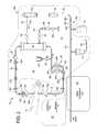
- FIG. 1illustrates a known access disconnection configuration.
- Bloodis drawn from an arm 12 of a patient through an arterial line 14 connected to the patient via an arterial needle 14 b . Blood is returned to patient 12 after it has been treated via a venous line 16 and venous needle 16 b .
- Needles 14 b and 16 bconnect to a shunt 12 a , which is placed in fluid communication with one of the patient's veins.
- Accidental disconnection of the arterial line 14 during treatmentis not as serious an issue because this situation simply eliminates the source of blood to the blood pump.
- Access disconnection of venous line 16 during treatmentis a serious concern however because arterial line 14 keeps feeding blood to the blood pump, while venous line 16 returns blood to a location outside of patient 12 .
- Another problem with systems that inject current into the extracorporeal circuitsoccurs if the dislodged needle reestablishes contact with the other needle physically or through leaked blood.
- the electrical parameter being sensede.g., impedance, may not change or not change enough to signal an access disconnection even though one has occurred.
- a further obstacleinvolves the addition of electrical contacts to the disposable portion of the blood treatment system.
- Metal or otherwise conductive members placed in the disposableadd manufacturing difficulty and cost.
- the examples described hereindisclose access disconnection systems and methods applicable, for example, to: plasmapherisis, hemodialysis (“HD”), hemofiltration (“HF”) and hemodiafiltration (“HDF”).
- the access disconnection systemsmay also be used with continuous renal replacement therapy (“CRRT”) treatments, which also require vascular access.
- CRRTcontinuous renal replacement therapy
- the access disconnection examples belowoperate with systems having a diffusion membrane or filter, such as a dialyzer, e.g., for HD or HDF, or a hemofilter, e.g., for HF or CRRT.
- a diffusion membrane or filtersuch as a dialyzer, e.g., for HD or HDF
- a hemofiltere.g., for HF or CRRT.
- Each of HD, HF, HDF and CRRTmay be referred to herein for convenience as a renal failure therapy.
- each of the systems described hereinmay be used with clinical or home-based machines.
- the systemsmay be employed in in-center HD, HF or HDF machines, which run throughout the day.
- the systemsmay be used with home HD, HF or HDF machines, which are operated at the patient's convenience.
- One such home systemis described in U.S. Pat. No. 8,029,454 (“the '454 Patent”), issued Oct. 4, 2011, entitled “High Convection Home Hemodialysis/Hemofiltration And Sorbent System”, filed Nov. 4, 2004, assigned to the assignee of the present application.
- Another such home systemis described in U.S. Pat. No. 8,721,884 (“the '884 Patent”), issued May 13, 2014, entitled “Hemodialysis Systems and Methods”, filed Feb. 7, 2013. The entire contents of both of the above references are incorporated herein by reference and relied upon.
- the access disconnection examples belowmay operate with systems having bagged or batch dialysis fluid supplies, which may include a single bag or multiple bags of dialysis fluid ganged together and used one after another.
- each of the access disconnection systems shown belowmay be used with a machine having an on-line source, such as one or more concentrate pump configured to combine one or more concentrate (liquid or solid) with water to form dialysis fluid on-line.
- non-invasive access disconnection systemsare described herein.
- the systemsdo not require a voltage or current to be injected into the blood circuit, which illuminates problems with sensitivity and patient grounding inherent in impedance sensing systems.
- the present systemsdo not rely on the connection or disconnection of an electrical loop, they are immune from the reestablishment of a conductive path with a dislodged needle via blood loss.
- the disclosed systemsin various embodiments communicate with a controller of the dialysis machine via wired or wireless connection.
- the addition of structure to the disposable tubing and/or cassette that the corresponding machine usesmay therefore be minimal or non-existent, which is desirable from cost and complexity standpoints.
- a renal failure therapy (HD, HF, HDF or CRRT) machineincludes a wave transmitter and receiver.
- a “transducer”is generally a device that converts an electrical signal (voltage or current) into a wave (e.g., acoustic, ultrasonic) or vice versa, converting the wave into an electrical signal.
- the transmitter and receivercan be a single transducer that at one time is used as an emitter, converting an electrical signal into a desired wave, and at another time is a receiver, converting a received wave into an output electrical signal.
- the transmitter and receivercan alternatively include an emitting transducer that is dedicated to converting an electrical signal into a desired wave and a separate receiving transducer that is dedicated to converting a received wave into an output electrical signal.
- a desired wavehas a desired frequency in one embodiment, which can be an acoustic or ultrasonic frequency.
- the one or more transducermay be, for example, piezoelectric, piezoresistive, magnetic, electroaucoustic, electromagnetic, inductive, capacitive, or resistive.
- the wave transmitter and receiveris provided in one embodiment on the chassis of a renal failure therapy machine, such as ones disclosed in the above-incorporated patents.
- the machinestypically have an arterial line running from the patient to a blood pump on the machine and a venous line running from a blood filter (dialyzer or hemofilter) to the patient.
- the wave transmitteris placed on the machine so that the venous line can be clamped up against the transmitter in one embodiment.
- the venous lineis the important blood line to monitor in one embodiment because it returns blood to the patient, thus its dislodgement could lead to the blood being returned instead to a place outside the patient.
- the wave transmitter and receiveris provided in another embodiment at a downstream location on the venous line.
- a small housingholds the transmitter and receiver (single or dual transducer) along with other electronics.
- the housingincludes structure, such as a clip or overlapping flaps that allow the housing to be removeably coupled at a desired location to the venous line.
- the other electronicscan include processing, memory and electronics needed to communicate wired or wirelessly with a processor of the renal failure therapy machine, such as a main control processor.
- a processor of the renal failure therapy machinesuch as a main control processor.
- One reason to locate the transmitter and receiver downstream on the venous linemay be to avoid noise generated at the machine and/or to receive a stronger reflected signal.
- the signalis reflected off of the needle access point of the venous needle in one embodiment. If the venous needle becomes dislodged from the patient, the reflected signal changes, which is sensed and acted upon. For example, the machine can shut down treatment, place itself into a safe mode, and alarm the patient. If the patient can restore the venous access, it may be possible to continue the same treatment. Alternatively, treatment is shut down for good, and the patient is instructed to fully disconnect himself or herself from the machine.
- the systemincludes software and electronics configured to analyze the transmitted (or incident) and reflected signals.
- the software and electronicsare provided in one embodiment on a main processor of the renal failure therapy machine.
- the software and electronicsare provided on a user interface or (“UI”) processor of the renal failure therapy machine.
- UIuser interface or
- the software and electronicsmay, but does not have to, be provided in the housing.
- the software and electronicsmay be provided redundantly at a first processor, e.g., the main control processor and at a second processor, e.g., at a safety processor.
- the machinecan shut down treatment, place itself into a safe mode, and alarm the patient if either of the redundant processors detects a needle dislodgement.
- the software and electronics configured to analyze the reflected signalmay be combined with any one or more other type of access disconnection system (“ADS”) to produce a hybrid redundant system.
- ADSaccess disconnection system
- the software and electronics configured to analyze the reflected signalmay be combined with any of the electrical impedance type ADS systems incorporated by reference above.
- the software and electronicsdetermine the Fourier transform spectral value (a complex number z) for each of the signals at a specified frequency.
- the software and electronicsuses the spectral values to calculate a reflection coefficient (R) and impedance ratio (I), which are in turn analyzed for a needle dislodgment.
- R and Iare likewise complex numbers z.
- R and Ieach has its own real part x and imaginary part y.
- the software and electronics of the present disclosureare further configured to calculate a magnitude and phase shift from the real and imaginary parts of each of the reflection coefficient (R) and the impedance ratio (I).
- the eight plotsinclude (i) a plot of the real part of the reflection coefficient (R) versus time, (ii) a plot of the real part of the impedance ratio (I) versus time, (iii) a plot of the magnitude of the reflection coefficient (R) versus time, (iv) a plot of the magnitude of the impedance ratio (I) versus time, (v) a plot of the imaginary part of the reflection coefficient (R) versus time, (vi) a plot of the imaginary part of the impedance ratio (I) versus time, (vii) a plot of the phase shift of the reflection coefficient (R) versus time, and (viii) a plot of the phase shift of the impedance ratio (I) versus time.
- plots (v) to (viii)show the best signal to noise ratio. It is accordingly contemplated for the software and electronics to look to any one, or more, or all of the data of plots (v) to (viii) to determine if an access disconnection event has taken place. In other alternative embodiments, the software and electronics to look to any one, or more, or all of the data of plots (i) to (iv) in combination with any one, or more, or all of the data of plots (v) to (viii) to determine if an access disconnection event has taken place.
- a renal failure therapy systemincludes: a blood filter; a blood pump in fluid communication with the blood filter; a dialysis fluid pump in fluid communication with the blood filter; a blood line for connection to a patient, the blood line in fluid communication with the blood filter; a transmitter positioned and arranged to receive a transmit signal and to transmit a wave into blood flowing through the blood line, the wave based on the transmit signal; a receiver positioned and arranged to receive the wave and to emit a received signal based on the received wave; and at least one processor for initiating the transmit signal and for receiving the received signal, the processor configured to convert the transmit and received signals into a frequency domain, extract spectral values for the converted transmit and received signals, calculate at least one of a reflection coefficient (R) or an impedance ratio (I) using the spectral values, and analyze an imaginary part of at least one of R or I to determine if an access disconnection event concerning fluid communication between the blood line and the patient has occurred
- the at least one processoranalyzes imaginary parts of both the reflection coefficient (R) and the impedance ratio (I) to determine if an access disconnection event concerning fluid communication between the blood line and the patient has occurred.
- the at least one processorfurther analyzes at least one of a real part of at least one of R or I, a phase shift of at least one of R or I, or a magnitude of at least one of R or I to determine if an access disconnection event concerning fluid communication between the blood line and the patient has occurred.
- phase shiftis provided as an angular value in degrees.
- the external spectral valueseach include a real and an imaginary part, leading to the imaginary parts of R and I.
- the spectral valuesare calculated at a specified frequency.
- the specified frequencyis in a range of 10 Hz to 12 Hz.
- the specified frequencyis determined based on empirical testing.
- the at least one processordetermines at least one baseline value for analysis during a period of time at the beginning of a treatment.
- the converted transmit and received signalseach include real and imaginary parts, leading to the imaginary parts of R and I.
- the imaginary parts of the reflection coefficient (R) and the impedance ratio (I)are provided as unitless numerical values.
- the renal failure therapy systemis a plasmapherisis, hemodialysis (“HD”), hemofiltration (“HF”), hemodiafiltration (“HDF”) or continuous renal replacement therapy (“CRRT”) system, and wherein the blood filter is a dialyzer or hemofilter.
- the blood filter, the blood pump, and the dialysis fluid pumpare housed in a machine, and the transmitter and the receiver are housed in a separate unit that communicates wirelessly with the machine.
- the blood filter, the blood pump, and the dialysis fluid pumpare housed in a machine, and the transmitter and the receiver are located at the machine.
- the at least one processoris part of a housing for the transmitter and the receiver, the housing configured to be attached to the blood line.
- the at least one processoris a first processor, and which includes a second, redundant at least one processor for receiving the transmit and received signals, the second processor configured to convert the transmit and received signals into the frequency domain, extract spectral values for the converted transmit and received signals, calculate at least one of a reflection coefficient (R) or an impedance ratio (I) using the spectral values, and analyze an imaginary part at least one of R or I to determine if an access disconnection event concerning fluid communication between the blood line and the patient has occurred.
- Rreflection coefficient
- Iimpedance ratio
- the blood lineis a venous blood line.
- the renal failure therapy system upon the disconnection outputis configured to perform at least one of: (i) shutting down a blood pump, (ii) activating a venous line clamp, and (iii) alerting the patient of the disconnection.
- the transmitter and the receiverare of at least one type selected from the group consisting of: a single transducer, multiple transducers, piezoelectric, electromagnetic, or any suitable combination thereof.
- the disconnection outputis of at least one type selected from the group consisting of: an electrical output, a radio frequency output, a microwave output, a continuous output, an intermittent output, an output occurring upon the change, a wireless output, or any suitable combination thereof.
- a renal failure therapy systemincludes: a blood filter; a blood pump in fluid communication with the blood filter; a dialysis fluid pump in fluid communication with the blood filter; a blood line for connection to a patient, the blood line in fluid communication with the blood filter; a transmitter positioned and arranged to receive a transmit signal and to transmit a wave into blood flowing through the blood line, the wave based on the transmit signal; a receiver positioned and arranged to receive the wave and to emit a received signal based on the received wave; and at least one processor for initiating the transmit signal and for receiving the received signal, the processor configured to convert the transmit and received signals into a frequency domain, extract spectral values for the converted transmit and received signals, calculate at least one of a reflection coefficient (R) or an impedance ratio (I) using the spectral values, and analyze plural ones of (i) an imaginary part of R, (ii) an imaginary part of I, (iii)
- the algorithmincludes determining that an access disconnection event concerning fluid communication between the blood line and the patient has occurred if any of the plural ones of (i) to (viii) indicates the access disconnection event.
- the algorithmincludes determining that an access disconnection event concerning fluid communication between the blood line and the patient has occurred if each of the plural ones of (i) to (viii) indicates the access disconnection event.
- the algorithmincludes determining that an access disconnection event concerning fluid communication between the blood line and the patient has occurred if multiple ones of the plural ones of (i) to (viii) indicate the access disconnection event.
- any of the features, functionality and alternatives described in connection with any one or more of FIGS. 1 to 6Hmay be combined with any of the other aspects listed herein, and any of the features, functionality and alternatives described in connection with any of the other one or more of FIGS. 1 to 6H .
- FIG. 1illustrates a known arterial and venous access configuration.
- FIG. 2is a schematic illustration of one embodiment of a renal failure therapy system having an access disconnection system and method of the present disclosure.
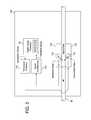
- FIG. 3is a schematic view illustrating an embodiment of the transmitter and receiver and associated electronics of the present disclosure in more detail.
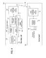
- FIG. 4is a schematic view illustrating another embodiment of the transmitter and receiver and associated electronics of the present disclosure in more detail.
- FIG. 5is a process flow diagram illustrating one access disconnection method embodiment of the present disclosure.
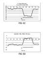
- FIGS. 6A to 6Hare plots of various signal metrics obtained from a test of the methodology of FIG. 5 .
- the examples described hereinare applicable to any medical fluid therapy system requiring vascular access.
- the examplesare particularly well suited for the control of kidney failure therapies, such as all forms of hemodialysis (“HD”), hemofiltration (“HF”), hemodiafiltration (“HDF”) and continuous renal replacement therapies (“CRRT”) requiring vascular access, referred to herein collectively or generally individually as renal failure therapy.
- the machines and any of the access disconnection systems and methods described hereinmay be used in clinical or home settings.
- the machine and the access disconnection systemsmay be employed in an in-center HD machine, which runs virtually continuously throughout the day. Alternatively, they may be used in a home HD machine, which can for example be run at night while the patient is sleeping.
- each of the vascular disconnection examples described hereinmay include a diffusion membrane or filter, such as a dialyzer, e.g., for HD or HDF, or a hemofilter, e.g., for HF.
- FIG. 2one embodiment for a renal failure therapy system 10 having the access disconnection system and method of the present disclosure is illustrated using an HD machine.
- system 10is shown having a very simplified version of the dialysis fluid or process fluid delivery circuit.
- the blood circuitis also simplified but not to the degree that the dialysis fluid circuit is simplified. It should be appreciated that the circuits have been simplified to make the description of the present disclosure easier, and that the systems if implemented would have additional structure and functionality, such as is found in the publications incorporated by reference above.
- System 10 of FIG. 2includes a blood circuit 20 .
- Blood circuit 20pulls blood from and returns blood to a patient 12 .
- Bloodis pulled from patient 12 via an arterial line 14 , and is returned to the patient via a venous line 16 .
- Arterial line 14includes an arterial line connector 14 a that connects to an arterial needle 14 b , which is in blood draw flow communication with patient 12 .
- Venous line 16includes a venous line connector 16 a that connects to a venous needle 16 b , which is in blood return flow communication with the patient.
- Arterial and venous lines 14 and 16also include line clamps 18 a and 18 v , which can be spring-loaded, fail-safe mechanical pinch clamps. Line clamps 18 a and 18 v are closed automatically in an emergency situation in one embodiment.
- Arterial and venous lines 14 and 16also include air or bubble detectors 22 a and 22 v , respectively, which can be ultrasonic air detectors.
- Air or bubble detectors 20 a and 20 vlook for air in the arterial and venous lines 14 and 16 , respectively. If air is detected by one of air detectors 22 a and 22 v , system 10 closes line clamps 18 a and 18 v , pauses the blood and dialysis fluid pumps and provides instructions to the patient to clear the air so that treatment can resume.
- a blood pump 30is located in arterial line 14 in the illustrated embodiment.
- blood pump 30includes a first blood pump pod 30 a and a second blood pump pod 30 b .
- Blood pump pod 30 aoperates with an inlet valve 32 i and an outlet valve 32 o .
- Blood pump pod 30 boperates with an inlet valve 34 i and an outlet valve 34 o .
- blood pump pods 30 a and 30 bare each blood receptacles that include a hard outer shell, e.g., spherical, with a flexible diaphragm located within the shell, forming a diaphragm pump. One side of each diaphragm receives blood, while the other side of each diaphragm is operated by negative and positive air pressure.
- Blood pump 30is alternatively a peristaltic pump operating with the arterial line 14 tube.
- a heparin vial 24 and heparin pump 26are located between blood pump 30 and blood filter 40 (e.g., dialyzer) in the illustrated embodiment.
- Heparin pump 26can be a pneumatic pump or a syringe pump (e.g., stepper motor driven syringe pump) Supplying heparin upstream of blood filter 40 helps to prevent clotting of the blood filter membranes.
- a control unit 50includes one or more processor and memory. Control unit receives air detection signals from air detectors 22 a and 22 v (and other sensors of system 10 , such as temperature sensors, blood leak detectors, conductivity sensors, pressure sensors, and in an embodiment, the access disconnection transducers of the present disclosure), and controls components such as line clamps 18 a and 18 v , blood pump 30 , heparin pump 26 , and the dialysis fluid pumps (described below).
- air detectors 22 a and 22 vand other sensors of system 10 , such as temperature sensors, blood leak detectors, conductivity sensors, pressure sensors, and in an embodiment, the access disconnection transducers of the present disclosure
- componentssuch as line clamps 18 a and 18 v , blood pump 30 , heparin pump 26 , and the dialysis fluid pumps (described below).
- Airtrap 28removes any air from the blood before the dialyzed blood is returned to patient 12 via venous line 16 .
- Airtrap 28can also have a pierceable septum that allows blood samples to be removed from blood circuit 20 .
- Dialysis fluid or dialysateis pumped along the outside of the membranes of blood filter 40 , while blood is pumped through the insides of the blood filter membranes.
- Dialysis fluid or dialysateis prepared beginning with the purification of water by water purification unit 60 .
- One suitable water purification unitis set forth in U.S. Patent Publication No. 2011/0197971, entitled, “Water Purification System and Method”, filed Apr. 25, 2011, the entire contents of which are incorporated herein by reference and relied upon.
- water purification unitincludes filters and other structure to purify tap water (e.g., remove pathogens and ions such as chlorine) so that the water is in one implementation below 0.03 endotoxin units/ml (“EU/ml”) and below 0.1 colony forming units/ml (“CFU/ml”).
- Water purification unit 60can be provided in a housing separate from the housing of the hemodialysis machine, which includes blood circuit 20 and a dialysis fluid circuit 70 .
- Dialysis fluid circuit 70is again highly simplified in FIG. 2 to ease illustration and to better highlight blood circuit 20 .
- Dialysis fluid circuit 70in actuality can include all of the relevant structure and functionality set forth in the publications incorporated by reference above. Certain features of dialysis fluid circuit 70 are illustrated in FIG. 2 .
- dialysis fluid circuit 70includes a to-blood filter dialysis fluid pump 64 .
- Pump 64is in one embodiment configured the same a blood pump 30 .
- Pump 64like pump 30 , includes a pair of pump pods, which again can be spherically configured. The two pump pods, like with blood pump 30 , are operated alternatingly so that one pump pod is filling with HD dialysis fluid, while the other pump pod is expelling HD dialysis fluid.
- Pump 64is a to-blood filter dialysis fluid pump.
- There is another dual pod pump 96like pump 64 , located in drain line 82 to push used dialysis fluid to drain.
- the third and fourth pumps, the concentrate pumps,can be single pod pumps because continuous pumping is not as important in mixing line 62 because there is a buffering dialysis fluid tank (not illustrated) between mixing line 62 and to-blood filter dialysis fluid pump 64 in one embodiment.
- a fifth pod pump (not illustrated) provided in drain line 82is used to remove a known amount of ultrafiltration (“UF”) when the HD therapy is provided.
- System 10keeps track of the UF pump to control and know how much ultrafiltrate has been removed from the patient. System 10 ensures that the necessary amount of ultrafiltrate is removed from the patient by the end of treatment.
- Each of the above-described pumpsmay alternatively be a peristaltic pump operating with a tube.
- purified water from water purification unit 60is pumped along mixing line 62 though bicarbonate cartridge 72 .
- Acid from container 74is pumped along mixing line 62 into the bicarbonated water flowing from bicarbonate cartridge 72 to form an electrolytically and physiologically compatible dialysis fluid solution.
- the pumps and temperature-compensated conductivity sensors used to properly mix the purified water with the bicarbonate and acidare not illustrated but are disclosed in detail in the publications incorporated by reference above.
- FIG. 2also illustrates that dialysis fluid is pumped along a fresh dialysis fluid line 76 , through a heater 78 and an ultrafilter 80 , before reaching blood filter 40 , after which the used dialysis fluid is pumped to drain via drain line 82 .
- Heater 78heats the dialysis fluid to body temperature or about 37° C.
- Ultrafilter 80further cleans and purifies the dialysis fluid before reaching blood filter 40 , filtering bugs or contaminants introduced for example via bicarbonate cartridge 72 or acid container 74 from the dialysis fluid.
- Dialysis fluid circuit 70also includes a sample port 84 in the illustrated embodiment. Dialysis fluid circuit 70 will further include a blood leak detector (not illustrated but used to detect if a blood filter 40 fiber is torn) and other components that are not illustrated, such as balance chambers, plural valves, and a dialysis fluid holding tank, all illustrated and described in detail in the publications incorporated by reference above.
- a blood leak detectornot illustrated but used to detect if a blood filter 40 fiber is torn
- other componentsthat are not illustrated, such as balance chambers, plural valves, and a dialysis fluid holding tank, all illustrated and described in detail in the publications incorporated by reference above.
- hemodialysis system 10is an online, pass-through system that pumps dialysis fluid through blood filter one time and then pumps the used dialysis fluid to drain.
- Both blood circuit 20 and dialysis fluid circuit 70may be hot water disinfected after each treatment, such that blood circuit 20 and dialysis fluid circuit 70 can be reused.
- blood circuit 20 including blood filter 40are hot water disinfected and reused daily for about one month, while dialysis fluid circuit 70 is hot water disinfected and reused for about six months.
- multiple bags of sterilized dialysis fluid or infusateare ganged together and used one after another.
- the emptied supply bagscan serve as drain or spent fluid bags.
- the machine 100 of system 10includes an enclosure as indicated by the dotted line of FIG. 2 .
- the enclosure of machine 100varies depending on the type of treatment, whether the treatment is in-center or a home treatment, and whether the dialysis fluid/infusate supply is a batch-type (e.g., bagged) or on-line.
- FIG. 2illustrates that machine 100 can be provided with a transmitter 102 and a receiver 104 , which are held in a common housing, and which straddle and contact venous line 16 .
- the transmitter 102 and the receiver 104are located inside the machine 100 .
- the transmitter 102 and the receiver 104are located outside the machine 100 in a remote or separate unit 120 , which may communicate with the machine 100 , for example, as discussed in greater detail below.
- transmitter 102 and receiver 104are configured similar to air detector 22 v , wherein transmitter 102 resides on one side of venous line 16 , while receiver 104 resides on the opposing side of venous tube 16 .
- Transmitter 102 and receiver 104are positioned close enough to each other to clamp venous line 16 in place.
- receiver 104is located in a different housing and at a different location from transmitter 102 .
- transmitter 102 and receiver 104each includes a transducer 110 .
- Transducers 110in one embodiment include a piezoelectric crystal. Transducers 110 in general transmit power from one type of system to another, e.g., from an electrical signal to a mechanical vibration and vice versa. In the piezoelectric embodiment, power is provided to piezoelectric crystal of transducer 110 of transmitter 102 in the form of electricity.
- FIG. 3illustrates a transducer excitation apparatus 112 , which applies an electrical field to the piezoelectric crystal of transducer 110 . The piezoelectric crystal undergoes mechanical deformation due to the electric field. In this manner, the crystal is induced to resonate (vibrate) at a certain frequency to produce ultrasonic waves.
- the crystalvibrates at a desired acoustic or ultrasonic frequency, which can be anywhere from 10 Hertz to 100 MegaHertz.
- the acoustic or ultrasound waves of the piezoelectric crystal of transducer 110 of transmitter 102are imparted to and travel through blood flowing through venous line 16 .
- Transmitter 102 in the illustrated embodimentis positioned in parallel with venous line 16 tube.
- the piezoelectric crystal of transducer 110on the other hand may be placed at an angle, e.g., forty-five degrees, relative to the venous line 16 tube to produce acoustic or ultrasound waves having a directional component towards venous needle 16 b .
- the emitted signaltravels down venous line 16 tube and reflects off of patient 12 at the access of venous needle 16 b .
- the reflected signaltravels back up venous line 16 and excites transducer 110 of receiver 104 , which is likewise a piezoelectric crystal in one embodiment.
- Transducer 110 of receiver 104outputs a corresponding electrical signal.
- transducer 110 of receiver 104is also mounted at an angle, e.g., forty-five degrees, relative to venous line 16 tube.
- the reflected wavesapply mechanical stress to transducer 110 of receiver 104 , causing the crystal of the transducer to become electrically charged and to vibrate at its resonant frequency.
- the reflected acoustic or ultrasound wavesmay have a different frequency than do the emitted acoustic or ultrasound waves, an effect known as the Doppler effect.
- the change in frequencyis dependent on the speed and direction of movement of blood flowing though the access site and whether or not venous needle 16 b is properly inserted into patient 12 .
- the electronics in system 10stores software that processes the received echoes to determine whether or not venous needle 16 b is properly inserted into patient 12 .
- a single transducer 110is provided for both transmitter 102 and receiver 104 , in which case a second piezoelectric crystal is not needed.
- transducer 110is used at one time as transmitter 102 and at another time as receiver 104 .
- FIG. 3also shows an embodiment of the electronics associated with system 10 .
- a digital signal processor (“DSP”) 50which can include onboard random access memory (“RAM”) and read only memory (“ROM”), sends an output signal to transducer excitation apparatus 112 .
- Excitation apparatus 112excites the crystal of transducer 110 of transmitter 102 as described above. Reflected waves cause receiver crystal of transducer 110 of receiver 104 (or the crystal of transducer 110 operating as both emitter and receiver) to vibrate and create an acoustic or ultrasound wave, which is sent to signal conditioning 114 .
- Signal conditioning 114in one embodiment includes an analog to digital (“A/D”) converter, which digitizes the reflected wave into a form that DSP 50 can process.
- Signal conditioning 114may, in another embodiment, contain demodulation circuitry to separate the signal components in a manner useful for Doppler calculations, for example.
- DSP 50using onboard software described in detail below detects a flow or access condition, a no-flow or full-access disconnection condition or a partial-flow or partial access disconnection condition.
- FIG. 4illustrates an alternative embodiment in which transmitter 102 and receiver 104 are not mounted on the enclosure of machine 100 but are instead clamped, wrapped about or otherwise fixed mechanically to venous line 16 , for example closer to venous line connector 16 a of venous line 16 , which connects to a venous needle 16 b .
- transmitter 102 and receiver 104are provided in a separate unit 120 having clamping structure or hook and pile flaps that wrap about venous line 16 .
- separate unit 120also houses transducer excitation apparatus 112 , signal conditioning 114 and a separate digital signal processor (“DSP”) 116 , having its own onboard RAM and ROM.
- DSPdigital signal processor
- Remote DSP 116communicates back and forth with a remote or wireless emitter/receiver 122 , such as a radio frequency (“RF”) transmitter/receiver.
- RFradio frequency
- Other remote signalsmay be used alternatively, such as microwave signals.
- unit 120is hard-wired to machine 100 and communicates via electrical signals, e.g., 4 to 20 mA or 0 to 5 VDC signals.
- Machine 100houses a wireless transmitter/receiver 52 , such as an RF transceiver.
- wireless transmitter/receiver 52 of machine 100sends messages to and receives messages from the remote unit 120 via its wireless transmitter/receiver 122 .
- Machine wireless transmitter/receiver 52in turn communicates back and forth with a central processing unit (“CPU”) 50 located within machine 100 .
- CPU 50in an embodiment is a supervisory processor that communicates via signals 56 with one or more delegate processor and circuit board or controller located within machine 100 .
- Transducers 110 , signal conditioning 114 , excitation apparatus 112 , DSP 116 and transmitter/receiver 122may be located on a printed circuit board (“PCB”) in one embodiment.
- the PCBcan be located within remote unit 120 , or within a separate housing (not illustrated).
- DSP 116 and its associated functionalityare located and performed, respectively, at CPU 50 .
- remote unit 120also includes a battery, a power supply or a combination of both, referred to generally herein as power supply 124 .
- Supply 124can be a rechargeable battery, for example.
- Supply 124powers the components of remote unit 120 , such as, signal conditioning 114 , DSP 116 and wireless communicator 122 .
- Power supply 124may be coupled to an audio, visual or audiovisual alarm that alerts the patient when the power supply needs to be recharged or replaced.
- remote wireless communicator or transceiver 122communicates with instrument communicator 52 via an RF signal 58 .
- Signal 58can be any of the following types: an electrical signal, a radio frequency signal, a microwave signal, a continuous signal, an intermittent signal, a signal sent only upon the sensing of the change and any suitable combination thereof.
- Signal 58may be a continuous e.g., digitalized, data stream, which CPU 50 my use to determine that an access disconnection event has occurred.
- CPU 50via signals 56 causes other components within machine 100 to take appropriate action, e.g., causes an audio, visual or audiovisual alarm to appear on and/or be sounded from a graphical user interface of machine 100 .
- CPU 50also likely causes blood pump 30 to shut down, occludes or closes blood line valves 18 a and 18 v , and puts the machine into a safe mode. Patient 12 may be allowed to try to reinstate venous access and continue treatment or be told to disconnect completely from the machine.
- remote DSP 116determines whether an access disconnection event has occurred.
- Remote DSP 116sends such determination, e.g., wirelessly via transceivers 122 and 52 to CPU 50 at predetermined intervals or when CPU 50 requests such information.
- CPU 50causes other components within machine 100 to take appropriate action as described above.
- wireless signal 58can be a continuous signal, an intermittent signal or a signal sent only upon the sensing of the change and any suitable combination thereof.
- remote unit 120sounds its own audio, visual or audiovisual alarm, which alerts a patient of an access disconnection.
- remote unit 120may or may not communicate with the renal failure therapy machine.
- remote unit 120can sound an alarm, while the machine shuts down one or more pumps, occludes or closes blood line valves 18 a and 18 v and places itself into a safe mode.
- the signal metrics described nextcan be performed on main CPU 50 of machine 100 or on remote DSP 116 of remote unit 120 .
- the signal metrics described nextare performed on both CPU 50 and a separate safety processor (not illustrated) as redundant ADS check.
- CPU 50 and the separate safety processorreceive the incident and reflected electrical signals in parallel in one embodiment.
- machine 100 alarmsgoes into a safe mode, shuts down blood pump 30 , closes blood clamps 18 a and 18 v , etc.
- method 150begins.
- processor 50 , 116converts the transmitted (incident) and received (reflected) acoustic ultrasound wave signals into the frequency domain, e.g., via taking the Fast Fourier transform of the signals.
- the transmitted or incident signalis the electrical signal commanded by the processor 50 , 116 to cause transducer excitation 112 to excite transducer crystal 110 of transmitter 102 to vibrate at a desired acoustic or ultrasound frequency.
- the received or reflected signalis the electrical signal that is outputted by transducer crystal 110 of receiver 104 based upon a reflected acoustic or ultrasound wave received at the transducer crystal.
- the transmitted (incident) signalmay be produced by a single excitation of a magnetic transducer, e.g., by a single wave of a sine or cosine cycle at 30 Hz.
- the transmitted (incident) signalmay be continuously repeated on a 500 millisecond (“msec”) interval, which may provide ample processing time after receiving the received (reflected) signal (e.g., using the Fast Fourier transform), while also providing adequate response time for the system to react to an access disconnect.
- the Fourier transformas is known in the art converts the transmitted and received signals from a time-based domain to a frequency domain. The Fourier transform results in a complex-valued function for each signal. That is, the results will have real and imaginary parts.
- processor 50 , 116extracts a spectral value at a specified frequency for each of the converted transmitted (incident) and received (reflected) signals, e.g., using the transmitted and received signals' Fourier transform spectra.
- a spectral valueis extracted at a specified frequency (e.g., 10 Hz) using a complex-valued function resulting from taking the Fast Fourier transform as discussed above.
- Each spectral valuemay include both real and imaginary parts.
- the specified frequencywhich may typically be about 10 Hz to 12 Hz, may be empirically determined based on a peak in a power spectrum of a raw venous line pressure signal, which may be calculated using signals converted into the frequency domain in the same manner as discussed above.
- the particular equipment being used and/or the flowrates being usedmay provide more robust results at a specified frequency other than 10 Hz to 12 Hz. It should be appreciated that many variables may impact extracted spectral values, such as blood flow rates and/or equipment specifications (e.g., tubing and needle sizes).
- blood flowratesmay vary (e.g., 0 to 800 mL/min) for different equipment, different patients, and/or different treatment regimens, as well as during the course of any given treatment.
- a specified frequencymay therefore be predetermined based upon typical flowrates (e.g., 50, 100, 200, 400, 600 or 800 mL/min) for a particular machine, equipment, patient, and/or treatment regimen.
- a specified frequencymay be dependent on a current blood flow rate, e.g., the specified frequency may be set at 10 Hz during low flow and 12 Hz during high flow.
- processor 50 , 116calculates a reflection coefficient (R) and an impedance ratio (I) based on the extracted spectral values for the converted transmitted (incident) and received (reflected) signals.
- the reflection coefficient (R) and the impedance ratio (I)may be calculated, for example, based on the following equations, where p r is an extracted spectral value for reflected pressure, and p i is an extracted spectral value for incident pressure:
- processor 50 , 116determines the real and imaginary parts for each of reflection coefficient (R) and an impedance ratio (I).
- R and Iare calculated from complex components (the real and imaginary parts from the extracted spectral values from the Fourier transform), R and I are both complex too, each having a real part and an imaginary part.
- p r and p iare both complex values (e.g., x+iy), based on the equations shown above, R and I will also be complex values.
- processor 50 , 116determines the magnitude and phase shift of (a) the reflection coefficient (R) and (b) the impedance ratio (I).
- the magnitudes and phase shifts of the reflection coefficient (R) and the impedance ratiomay be determined using the real and imaginary parts of the reflection coefficient (R), and the real and imaginary parts of the impedance ratio (I), respectively.
- magnitudemay be determined as the square root of the sum of the real part squared and the imaginary part squared
- phase shiftmay be determined as the arctangent of the quotient of the imaginary part divided by the real part.
- processor 50 , 116uses data from at least one of (i) the imaginary part of R or (ii) the imaginary part of I to determine if an access disconnection has occurred.
- Processor 50 , 116may use either (i) or (ii) or both (i) and (ii) to determine if an access disconnection has occurred.
- Processor 16may use either (i) or (ii) or both (i) and (ii) in combination with any one or more of (iii) phase shift of I, (iv) phase shift of R, (v) real part of R, (vi) real part of I, (vii) magnitude of R, or (viii) magnitude of I to determine if an access disconnection has occurred.
- (i) to (iv)provide the best signal to noise ratios.
- processor 50 , 116takes corrective measures, e.g., causes at least one machine 100 to alarm, go into a safe mode, shut down blood pump 30 , close blood clamps 18 a and 18 v , etc.
- an access disconnection or access disconnection eventmay include a full or partial dislodgement of the needle from patient 12 .
- processor 50 , 116determines whether treatment has ended. If treatment has not ended, processor 50 , 116 returns to block 154 and repeats the steps of blocks 154 to 164 .
- the loop between block 154 to diamond 168continues (system 10 continuously looks for an access disconnection or at a specified cycle frequency) until an access disconnection has occurred, after which corrective action is taken at block 166 , or treatment ends as determined at diamond 168 , after which method 150 ends, as illustrated at oval 170 .
- corrective actionmay include any one or more of providing an audio, visual or audio-visual alarm, closing one or more line clamp, shutting down one or more pump, e.g., the blood pump, placing the machine in a safe mode until the access disconnection can be fixed, and/or shutting treatment down completely.
- a pumpe.g., the blood pump
- the loop between block 154 to diamond 168may occur, for example, every 500 msec (2 Hz), or at any other suitable frequency (e.g., 0.5 Hz to 10 Hz). It should be appreciated that the frequency interval for completing the loop between block 154 and diamond 168 may be selected to provide an adequate amount of time to receive the reflective signals and to complete processing of the transmitted and received signals, as well as an adequate response time for determining an access disconnect. The frequency between block 154 and diamond 168 is also chosen so as to prevent an unacceptable level of false positives, thereby advantageously resulting in a robust access disconnect system.
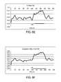
- FIGS. 6A to 6Hillustrate results of a test performed mimicking the pertinent structure of system 10 illustrated and described above, including the use of a transducer excited with a single sinusoidal wave cycle at 30 Hz to create transmitted (incident) and received (reflected) signals for an acoustic wave every 500 msec.
- the flowratewas set at a common value for a renal failure therapy in a low flow mode, namely, 50 mL/min.
- a needle dislodgement mimicking a venous needle dislodgementwas simulated at about time equaling 90 to about 150 seconds after the beginning of the test illustrated in the plots. Method 150 described above was performed over a time from zero to about 200 seconds and generated the following eight plots: FIG.
- FIG. 6Aimaginary part of R, FIG. 6B imaginary part of I, FIG. 6C phase shift of R, FIG. 6D phase shift of I, FIG. 6E real part of R, FIG. 6F real part of I, FIG. 6G magnitude of R, and FIG. 6H magnitude of I.
- FIG. 6A imaginary part of R, FIG. 6B imaginary part of I, FIG. 6C phase shift of I, and FIG. 6D phase shift of Rshowed the best signal to noise ratios, however, the needle dislodgement was detected in each of the plots of FIGS. 6A to 6H .
- processor 50 , 116be configured to look at the data of the plots of FIG. 6A and/or FIG. 6B , or FIG. 6A and/or FIG. 6B in combination with any one or more of the data of plots of FIGS. 6C to 6H to determine if an access disconnection has occurred.
- data from at least one of the plots of FIG. 6A or FIG. 6Bis analyzed.
- the data from four plots( FIG. 6A , FIG. 6B , FIG. 6C and FIG. 6D ) is analyzed in parallel to look for an access disconnection.
- Processor 50 , 116may be programmed to signal an access disconnection event when (a) any one of the four sets of data indicates disconnection, (b) two of the four sets indicate disconnection, (c) three of the four sets indicate disconnection or (d) all four sets indicate disconnection. Variations (a) to (d) vary from most sensitive (good for detection, but bad for false triggering) to least sensitive (good for preventing false triggering).
- processor 50 , 116may be configured to store a value for the y-axis of the plots of FIGS. 6A to 6H ( FIGS. 6A, 6B and 6E to 6H are unitless, while phase shift in FIGS. 6C and 6D is measured in degrees). If the calculated value is different from the stored value by more than a certain amount, processor 50 , 116 determines that an access disconnection has occurred.
- the stored (compared against) valuemay be common for all patients, be selected for each patient, or be selected for each of different groups of patients. In an alternative embodiment, processor 50 , 116 determines the stored value at the beginning of each treatment.
- processor 50 , 116 of system 10may use the beginning of treatment, when it is assumed that needle access is good, to establish a baseline comparison value, which is then compared against with the calculated values over the rest of the treatment.
- the baseline valuemay be determined for a period of 30 seconds at the beginning of each treatment, or for any suitable period of time (e.g., 10 seconds, 60 seconds, 90 seconds).
- a separate baseline valveis determined for each of the plots of 6 A to 6 H used in the access disconnection evaluation.
- transmitter 102 and receiver 104can be located at machine 100 or remote from machine 100 , along venous line 16 .
- Method 150may be performed at machine CPU 50 , at remote sensing processor 116 , or using both processors. Also, while system 10 and method 150 are primarily concerned with venous line 16 disconnection, they may be applied alternatively or additionally to arterial line 14 disconnection.
- Certain known access disconnection systemsrely on the breaking of an electrical circuit to detect an access problem.
- One problem with these systemsis that a needle dislodging from the patient does not always break the electrical circuit.
- a venous needlecan for example dislodge from the patient but direct the flow of blood over the access from which the needle has been dislodged or over the other (e.g., arterial) needle to complete or re-complete the electrical circuit.
- bloodwould not be returned to the patient but no alarm would sound.
- acoustic or ultrasound systems described hereinwith an electrical impedance type of system, such as one of the impedance systems of the '098 and '480 Patents. Either system can detect an access disconnection and cause machine 100 to alarm, go into a safe mode, shut down blood pump 30 , close blood clamps 18 a and 18 v , etc.
Landscapes
- Health & Medical Sciences (AREA)
- Heart & Thoracic Surgery (AREA)
- Vascular Medicine (AREA)
- Life Sciences & Earth Sciences (AREA)
- Engineering & Computer Science (AREA)
- Anesthesiology (AREA)
- Biomedical Technology (AREA)
- Hematology (AREA)
- Animal Behavior & Ethology (AREA)
- General Health & Medical Sciences (AREA)
- Public Health (AREA)
- Veterinary Medicine (AREA)
- Cardiology (AREA)
- Emergency Medicine (AREA)
- Urology & Nephrology (AREA)
- External Artificial Organs (AREA)
Abstract
Description
Claims (24)
Priority Applications (3)
| Application Number | Priority Date | Filing Date | Title |
|---|---|---|---|
| US14/978,954US10413654B2 (en) | 2015-12-22 | 2015-12-22 | Access disconnection system and method using signal metrics |
| EP16820520.1AEP3393546B1 (en) | 2015-12-22 | 2016-12-15 | System for detection of access disconnection |
| PCT/US2016/066883WO2017112517A1 (en) | 2015-12-22 | 2016-12-15 | Access disconnection system and method using signal metrics |
Applications Claiming Priority (1)
| Application Number | Priority Date | Filing Date | Title |
|---|---|---|---|
| US14/978,954US10413654B2 (en) | 2015-12-22 | 2015-12-22 | Access disconnection system and method using signal metrics |
Publications (2)
| Publication Number | Publication Date |
|---|---|
| US20170173253A1 US20170173253A1 (en) | 2017-06-22 |
| US10413654B2true US10413654B2 (en) | 2019-09-17 |
Family
ID=57708852
Family Applications (1)
| Application Number | Title | Priority Date | Filing Date |
|---|---|---|---|
| US14/978,954Active2037-04-09US10413654B2 (en) | 2015-12-22 | 2015-12-22 | Access disconnection system and method using signal metrics |
Country Status (3)
| Country | Link |
|---|---|
| US (1) | US10413654B2 (en) |
| EP (1) | EP3393546B1 (en) |
| WO (1) | WO2017112517A1 (en) |
Cited By (1)
| Publication number | Priority date | Publication date | Assignee | Title |
|---|---|---|---|---|
| US20220355086A1 (en)* | 2019-10-31 | 2022-11-10 | Musc Foundation For Research Development | Ultrasound-based shunt flow detection |
Families Citing this family (9)
| Publication number | Priority date | Publication date | Assignee | Title |
|---|---|---|---|---|
| US11826545B2 (en)* | 2016-09-08 | 2023-11-28 | Fresenius Medical Care Holdings, Inc. | Optical blood detection system |
| US20180280509A1 (en)* | 2017-03-28 | 2018-10-04 | Robert SCHENA | Treatment of blood |
| EP3656415B1 (en)* | 2017-07-21 | 2024-06-05 | Nikkiso Co., Ltd. | Blood purification apparatus |
| US10881347B2 (en) | 2017-12-29 | 2021-01-05 | Fresenius Medical Care Holdings, Inc. | Closed loop dialysis treatment using adaptive ultrafiltration rates |
| US10391220B2 (en) | 2018-01-12 | 2019-08-27 | Fresnius Medical Care Holdings, Inc. | Virtual kidney donation |
| US11529449B2 (en) | 2019-04-15 | 2022-12-20 | Medtronic, Inc. | Medical device dislodgment detection |
| CA3188633A1 (en)* | 2020-07-02 | 2022-01-06 | Fresenius Medical Care Holdings, Inc. | System and method for detecting venous needle dislodgement |
| WO2022010635A1 (en) | 2020-07-08 | 2022-01-13 | Fresenius Medical Care Deutschland Gmbh | Parabiotic dialysis systems and techniques |
| WO2025090713A1 (en) | 2023-10-27 | 2025-05-01 | Fresenius Medical Care Holdings, Inc. | Needle dislodgement detection systems and methods |
Citations (96)
| Publication number | Priority date | Publication date | Assignee | Title |
|---|---|---|---|---|
| US3882861A (en) | 1973-09-24 | 1975-05-13 | Vital Assists | Auxiliary control for a blood pump |
| US3946731A (en) | 1971-01-20 | 1976-03-30 | Lichtenstein Eric Stefan | Apparatus for extracorporeal treatment of blood |
| US4185641A (en) | 1978-08-23 | 1980-01-29 | Hewlett-Packard Company | Pressure dome |
| US4239047A (en) | 1978-05-22 | 1980-12-16 | William L. Griggs, III | Method and apparatus for aurally determining presence or absence of pathological stenosis |
| US4277227A (en) | 1979-07-02 | 1981-07-07 | Imed Corporation | Apparatus for converting a pump to a controller |
| US4353368A (en) | 1977-12-23 | 1982-10-12 | Ceske Vysoke Uceni Technicke | Device for hemodialysis |
| US4392847A (en) | 1979-01-08 | 1983-07-12 | Whitney Douglass G | Injection and monitoring system |
| US4450527A (en) | 1982-06-29 | 1984-05-22 | Bomed Medical Mfg. Ltd. | Noninvasive continuous cardiac output monitor |
| EP0121931A2 (en) | 1983-04-11 | 1984-10-17 | Ivac Corporation | Fault detection apparatus for parenteral infusion system |
| US4501483A (en) | 1983-09-02 | 1985-02-26 | Eastman Kodak Company | Fuser apparatus |
| US4541282A (en) | 1984-03-06 | 1985-09-17 | Honeywell Inc. | Method of producing a uniform fluid-tight seal between a thin, flexible member and a support and an apparatus utilizing the same |
| US4648869A (en) | 1985-12-04 | 1987-03-10 | American Hospital Supply Corporation | Automatic infiltration detection system and method |
| US4710163A (en) | 1986-06-06 | 1987-12-01 | Ivac Corporation | Detection of fluid flow faults in the parenteral administration of fluids |
| EP0300315A1 (en) | 1987-07-23 | 1989-01-25 | Siemens Aktiengesellschaft | Shock wave generator for an apparatus for non-contact disintegration of concrements, present in a body |
| US4828543A (en) | 1986-04-03 | 1989-05-09 | Weiss Paul I | Extracorporeal circulation apparatus |
| US4846792A (en) | 1988-03-08 | 1989-07-11 | Baxter International Inc. | Automatic infiltration detection system and method |
| EP0361793A2 (en) | 1988-09-26 | 1990-04-04 | Baxter International Inc. | An In-Line infiltration detection apparatus and method |
| US4923598A (en) | 1987-06-23 | 1990-05-08 | Fresenius Ag | Apparatus for the treatment of blood in particular for hemodialysis and hemofiltration |
| US4979940A (en) | 1988-03-08 | 1990-12-25 | Baxter International Inc. | Infusion system, methodology, and algorithm for identifying patient-induced pressure artifacts |
| US4981467A (en) | 1990-02-27 | 1991-01-01 | Baxter International Inc. | Apparatus and method for the detection of air in fluid delivery systems |
| US5026348A (en) | 1988-06-06 | 1991-06-25 | The General Hospital Corporation | Apparatus and method for the detection of IV catheter obstruction and extravasation |
| US5100374A (en) | 1989-01-31 | 1992-03-31 | Aisin Seiki Kabushiki Kaisha | Apparatus for driving blood pump |
| US5146414A (en) | 1990-04-18 | 1992-09-08 | Interflo Medical, Inc. | Method and apparatus for continuously measuring volumetric flow |
| US5311871A (en) | 1993-01-12 | 1994-05-17 | Yock Paul G | Syringe with ultrasound emitting transducer for flow-directed cannulation of arteries and veins |
| US5427695A (en) | 1993-07-26 | 1995-06-27 | Baxter International Inc. | Systems and methods for on line collecting and resuspending cellular-rich blood products like platelet concentrate |
| US5557263A (en) | 1992-07-22 | 1996-09-17 | Health Sense International, Inc. | System for detection of electrically conductive fluids |
| WO1997010013A1 (en) | 1995-09-12 | 1997-03-20 | Gambro Ab | Method and arrangement for detecting the condition of a blood vessel access |
| DE19609698A1 (en) | 1996-03-13 | 1997-09-18 | Metrax Gmbh | Blood pressure and pulse rate measuring apparatus |
| US5693008A (en) | 1995-06-07 | 1997-12-02 | Cobe Laboratories, Inc. | Dialysis blood tubing set |
| US5790036A (en) | 1992-07-22 | 1998-08-04 | Health Sense International, Inc. | Sensor material for use in detection of electrically conductive fluids |
| US5830365A (en) | 1995-08-05 | 1998-11-03 | Fresenius Ag | Means for determining hemodynamic parameters during extracorporeal blood treatment |
| US5863421A (en) | 1995-02-13 | 1999-01-26 | Aksys, Ltd. | Hemodialysis machine with automatic priming by induced pressure pulses |
| EP0895787A1 (en) | 1997-08-06 | 1999-02-10 | Fresenius Medical Care Deutschland GmbH | Method for monitoring a blood vessel access during a dialysis treatment and apparatus for dialysis treatment with a device for monitoring a blood vessel access |
| US5910252A (en) | 1993-02-12 | 1999-06-08 | Cobe Laboratories, Inc. | Technique for extracorporeal treatment of blood |
| WO1999029356A1 (en) | 1997-12-05 | 1999-06-17 | Meier Peter F | Method and device for monitoring a catheter unit |
| DE19848235C1 (en) | 1998-10-20 | 2000-03-16 | Fresenius Medical Care De Gmbh | Method for monitoring supply to vessel and extra-corporeal blood treatment device for monitoring supply to vessel; inputs blood circulation pressure to computer to calculate values to identify errors in supply during dialysis |
| WO2000018451A1 (en) | 1998-09-25 | 2000-04-06 | The Regents Of The University Of Michigan | Determining blood flow rate in a vessel |
| US6066261A (en) | 1997-12-23 | 2000-05-23 | Fresenius Medical Care Deutschland Gmbh | Method of monitoring part of a blood treatment machine and a blood treatment machine with a monitoring device |
| US6071421A (en) | 1991-12-23 | 2000-06-06 | Baxter International Inc. | Systems and methods for obtaining a platelet suspension having a reduced number of leukocytes |
| US6167765B1 (en) | 1998-09-25 | 2001-01-02 | The Regents Of The University Of Michigan | System and method for determining the flow rate of blood in a vessel using doppler frequency signals |
| US6187199B1 (en) | 1997-01-24 | 2001-02-13 | Fresenius Medical Care Deutschland Gmbh | Process and device for determining hemodialysis parameters |
| US6200485B1 (en) | 1991-10-11 | 2001-03-13 | Chidren's Hospital Medical Center | Hemofiltration system and method |
| US6337049B1 (en) | 1998-08-28 | 2002-01-08 | Yehuda Tamari | Soft shell venous reservoir |
| US20020004636A1 (en) | 2000-07-03 | 2002-01-10 | Keisuke Tsubata | Pulse wave detecting apparatus |
| US20020198483A1 (en) | 2001-06-22 | 2002-12-26 | Ramesh Wariar | Needle dislodgement detection |
| WO2002102441A1 (en) | 2001-06-15 | 2002-12-27 | Gambro Lundia Ab | Method and device for sensing the detachment of the venous needle from a patient during dialysis |
| US20030009123A1 (en) | 2001-07-07 | 2003-01-09 | Nxstage Medical, Inc. | Method and aparatus for leak detection in a fluid line |
| WO2003002174A1 (en) | 2001-06-29 | 2003-01-09 | Gambro Lundia Ab | Method and device for detecting the detachment of the venous needle from a patient during dialysis |
| US20030128125A1 (en) | 2002-01-04 | 2003-07-10 | Burbank Jeffrey H. | Method and apparatus for machine error detection by combining multiple sensor inputs |
| US20030130607A1 (en) | 2001-06-15 | 2003-07-10 | Annalisa Delnevo | Blood circuit for a dialysis machine and corresponding dialysis machine |
| WO2003058608A2 (en) | 2002-01-04 | 2003-07-17 | Nxstage Medical, Inc. | Method and apparatus for leak detection in blood circuits combining external fluid detection and air infiltration detection |
| WO2003058567A2 (en) | 2002-01-04 | 2003-07-17 | Nxstage Medical, Inc. | Method and apparatus for error warning with multiple alarm levels and types |
| US20030152482A1 (en) | 2002-02-14 | 2003-08-14 | O'mahony John J. | Method and apparatus for an extracorporeal treatment device to control blood withdrawal and infusion |
| US6623443B1 (en) | 1999-01-14 | 2003-09-23 | Hans-Dietrich Polaschegg | Method and device for the detection of stenosis in extra-corporeal blood treatment |
| US6649063B2 (en) | 2001-07-12 | 2003-11-18 | Nxstage Medical, Inc. | Method for performing renal replacement therapy including producing sterile replacement fluid in a renal replacement therapy unit |
| US6663585B1 (en) | 1997-09-06 | 2003-12-16 | Fresenius Medical Care Deutschland Gmbh | Method and device for monitoring vessel access during extracorporeal blood treatment |
| US20040030277A1 (en) | 2000-11-02 | 2004-02-12 | Chf Solutions, Inc. | Method and apparatus for blood withdrawal and infusion using a pressure controller |
| US20040041792A1 (en) | 2002-09-03 | 2004-03-04 | Criscione John C. | Keypad input device |
| US6730055B2 (en) | 2000-03-09 | 2004-05-04 | Gambro Inc. | Extracorporeal blood processing methods and apparatus |
| US6736789B1 (en) | 1997-10-21 | 2004-05-18 | Fresenius Medical Care Deutschland Gmbh | Method and device for extracorporeal blood treatment with a means for continuous monitoring of the extracorporeal blood treatment |
| US6767333B1 (en) | 1999-08-27 | 2004-07-27 | Fresenius Medical Care Deutschland | Safety device for a blood treatment machine and a method of increasing the safety of a blood treatment machine |
| US6773670B2 (en) | 2001-02-09 | 2004-08-10 | Cardiovention, Inc. C/O The Brenner Group, Inc. | Blood filter having a sensor for active gas removal and methods of use |
| US6780159B2 (en) | 2001-01-16 | 2004-08-24 | Biomedical Acoustic Research Corporation | Acoustic detection of vascular conditions |
| US20040186409A1 (en) | 2003-01-28 | 2004-09-23 | Gambro Dasco S.P.A. | Apparatus and method for monitoring a vascular access of a patient subjected to an extracorporeal blood treatment |
| US6804991B2 (en) | 2002-01-15 | 2004-10-19 | Fresenius Medical Care Deutschland Gmbh | Method and device for detecting a leakage in a fluid system of a blood treatment apparatus |
| EP1472973A1 (en) | 2003-04-28 | 2004-11-03 | Nemoto Kyorindo Co., Ltd. | Leak detector using pulse signals |
| US6827698B1 (en) | 1999-04-16 | 2004-12-07 | Fresenius Medical Care Deutschland Gmbh | Method and device for determining blood flow in a vascular access |
| US20050010118A1 (en) | 2003-07-10 | 2005-01-13 | Nikkiso Co. Ltd. | Method and device for measuring pulse rate, blood pressure, and monitoring blood vessel access |
| JP2005040518A (en) | 2003-07-25 | 2005-02-17 | Toin Gakuen | Access trouble detection system in dialysis |
| WO2005019416A2 (en) | 2003-08-13 | 2005-03-03 | Moll Family Trust | Method and device for monitoring loss of body fluid and dislodgment of medical instrument from body |
| US6880404B2 (en) | 2000-07-08 | 2005-04-19 | Mhm Harzbecher Medizintechnik Gmbh | System elements for measuring pressure in extracorporeal circuits |
| US6899691B2 (en) | 1999-12-22 | 2005-05-31 | Gambro Inc. | Extracorporeal blood processing methods and apparatus |
| US20050131332A1 (en) | 2003-11-05 | 2005-06-16 | Thomas Kelly | High convection home hemodialysis/hemofiltration and sorbent system |
| US20060081517A1 (en) | 2004-10-15 | 2006-04-20 | Nikkiso Co. Ltd. | Hemodialysis device |
| JP2006110118A (en) | 2004-10-15 | 2006-04-27 | Nikkiso Co Ltd | Blood purification apparatus and monitoring method thereof |
| US20060122552A1 (en) | 2004-12-03 | 2006-06-08 | Chf Solutions Inc. | Extracorporeal blood treatment and system having reversible blood pumps |
| WO2006122001A2 (en) | 2005-05-06 | 2006-11-16 | Vasonova, Inc. | Method and apparatus for endovascular device guiding and positioning |
| EP1736185A2 (en) | 2005-06-20 | 2006-12-27 | Delphi Technologies, Inc. | Needle disengagement sensing mechanism |
| US20070004997A1 (en) | 1999-12-22 | 2007-01-04 | Gambro, Inc. | Extracorporeal Blood Processing Methods With Multiple Alarm Levels |
| US20070010779A1 (en) | 2005-07-07 | 2007-01-11 | Utterberg David S | Blood leak monitoring method and apparatus |
| US20070078368A1 (en) | 2000-01-10 | 2007-04-05 | Gambro, Inc. | Extracorporeal Blood Processing Methods With Return-Flow Alarm |
| US20070108128A1 (en) | 2003-11-25 | 2007-05-17 | Pascal Kopperschmidt | Method and device for the detection of disruptions of the blood flow in an extracorporeal blood circuit |
| US20070179433A1 (en) | 2004-02-12 | 2007-08-02 | Lennart Jonsson | Pressure sensing |
| US20080108930A1 (en) | 2006-11-03 | 2008-05-08 | The Regents Of The University Of Michigan | Methods and Systems for Determining Volume Flow in a Blood or Fluid Conduit, Motion, and Mechanical Properties of Structures Within the Body |
| US20080171960A1 (en) | 2006-10-30 | 2008-07-17 | Lifebridge Medizintechnik Ag | Apparatus for making extracorporeal blood circulation available |
| US7410473B2 (en) | 2000-09-12 | 2008-08-12 | Chf Solutions Inc. | Blood pump having a disposable blood filter with integrated pressure sensors |
| US20080195022A1 (en) | 2003-10-02 | 2008-08-14 | Minnetronix Inc. | Continuous volume detection for a reservoir in a fluid circuit of a medical system |
| US20080214979A1 (en) | 2003-11-07 | 2008-09-04 | Nxstage Medical, Inc. | Methods and Apparatus For Leak Detection in Blood Processing Systems |
| DE102009007806A1 (en) | 2009-02-06 | 2010-08-12 | Fresenius Medical Care Deutschland Gmbh | Apparatus and method for vibrational excitation of at least a portion of a vascular access device for monitoring thereof |
| US20110046533A1 (en) | 2008-04-01 | 2011-02-24 | David Stefani | Apparatus and a method for monitoring a vascular access |
| US20110160637A1 (en)* | 2009-12-31 | 2011-06-30 | Fresenius Medical Care Holdings, Inc. | Detecting Blood Flow Degradation |
| US8152751B2 (en) | 2007-02-09 | 2012-04-10 | Baxter International Inc. | Acoustic access disconnection systems and methods |
| EP2442725A2 (en) | 2009-06-18 | 2012-04-25 | Quanta Fluid Solutions Ltd | Vascular access monitoring device |
| US8197421B2 (en) | 2002-04-19 | 2012-06-12 | Pelikan Technologies, Inc. | Method and apparatus for penetrating tissue |
| US8197431B2 (en)* | 2007-09-21 | 2012-06-12 | Baxter International Inc. | Acoustic access disconnect detection system |
| US20140298891A1 (en)* | 2011-06-23 | 2014-10-09 | Gambro Lundia Ab | Detecting blood path disruption in extracorpreal blood processing |
- 2015
- 2015-12-22USUS14/978,954patent/US10413654B2/enactiveActive
- 2016
- 2016-12-15EPEP16820520.1Apatent/EP3393546B1/enactiveActive
- 2016-12-15WOPCT/US2016/066883patent/WO2017112517A1/ennot_activeCeased
Patent Citations (134)
| Publication number | Priority date | Publication date | Assignee | Title |
|---|---|---|---|---|
| US3946731A (en) | 1971-01-20 | 1976-03-30 | Lichtenstein Eric Stefan | Apparatus for extracorporeal treatment of blood |
| US3882861A (en) | 1973-09-24 | 1975-05-13 | Vital Assists | Auxiliary control for a blood pump |
| US4353368A (en) | 1977-12-23 | 1982-10-12 | Ceske Vysoke Uceni Technicke | Device for hemodialysis |
| US4239047A (en) | 1978-05-22 | 1980-12-16 | William L. Griggs, III | Method and apparatus for aurally determining presence or absence of pathological stenosis |
| US4185641A (en) | 1978-08-23 | 1980-01-29 | Hewlett-Packard Company | Pressure dome |
| US4392847A (en) | 1979-01-08 | 1983-07-12 | Whitney Douglass G | Injection and monitoring system |
| US4277227A (en) | 1979-07-02 | 1981-07-07 | Imed Corporation | Apparatus for converting a pump to a controller |
| US4450527A (en) | 1982-06-29 | 1984-05-22 | Bomed Medical Mfg. Ltd. | Noninvasive continuous cardiac output monitor |
| EP0121931A2 (en) | 1983-04-11 | 1984-10-17 | Ivac Corporation | Fault detection apparatus for parenteral infusion system |
| US4534756A (en) | 1983-04-11 | 1985-08-13 | Ivac Corporation | Fault detection apparatus and method for parenteral infusion system |
| US4501483A (en) | 1983-09-02 | 1985-02-26 | Eastman Kodak Company | Fuser apparatus |
| US4541282A (en) | 1984-03-06 | 1985-09-17 | Honeywell Inc. | Method of producing a uniform fluid-tight seal between a thin, flexible member and a support and an apparatus utilizing the same |
| US4648869A (en) | 1985-12-04 | 1987-03-10 | American Hospital Supply Corporation | Automatic infiltration detection system and method |
| EP0232599A1 (en) | 1985-12-04 | 1987-08-19 | BAXTER INTERNATIONAL INC. (a Delaware corporation) | Automatic infiltration detection system |
| US4828543A (en) | 1986-04-03 | 1989-05-09 | Weiss Paul I | Extracorporeal circulation apparatus |
| US4710163A (en) | 1986-06-06 | 1987-12-01 | Ivac Corporation | Detection of fluid flow faults in the parenteral administration of fluids |
| US4923598A (en) | 1987-06-23 | 1990-05-08 | Fresenius Ag | Apparatus for the treatment of blood in particular for hemodialysis and hemofiltration |
| EP0300315A1 (en) | 1987-07-23 | 1989-01-25 | Siemens Aktiengesellschaft | Shock wave generator for an apparatus for non-contact disintegration of concrements, present in a body |
| US4972826A (en) | 1987-07-23 | 1990-11-27 | Siemens Aktiengesellschaft | Shock wave generator for an extracorporeal lithotripsy apparatus |
| US4846792A (en) | 1988-03-08 | 1989-07-11 | Baxter International Inc. | Automatic infiltration detection system and method |
| EP0332330A2 (en) | 1988-03-08 | 1989-09-13 | BAXTER INTERNATIONAL INC. (a Delaware corporation) | Automatic infiltration detection system |
| US4979940A (en) | 1988-03-08 | 1990-12-25 | Baxter International Inc. | Infusion system, methodology, and algorithm for identifying patient-induced pressure artifacts |
| US5026348A (en) | 1988-06-06 | 1991-06-25 | The General Hospital Corporation | Apparatus and method for the detection of IV catheter obstruction and extravasation |
| EP0361793A2 (en) | 1988-09-26 | 1990-04-04 | Baxter International Inc. | An In-Line infiltration detection apparatus and method |
| US4959050A (en) | 1988-09-26 | 1990-09-25 | Baxter International Inc. | In-line infiltration detection apparatus and method |
| US5100374A (en) | 1989-01-31 | 1992-03-31 | Aisin Seiki Kabushiki Kaisha | Apparatus for driving blood pump |
| WO1991000113A2 (en) | 1989-06-22 | 1991-01-10 | Baxter International Inc. | Infusion system, methodology, and algorithm for identifying patient-induced pressure artifacts |
| US4981467A (en) | 1990-02-27 | 1991-01-01 | Baxter International Inc. | Apparatus and method for the detection of air in fluid delivery systems |
| US5146414A (en) | 1990-04-18 | 1992-09-08 | Interflo Medical, Inc. | Method and apparatus for continuously measuring volumetric flow |
| US6200485C1 (en) | 1991-10-11 | 2002-05-21 | Childrens Hosp Medical Center | Hemofiltration system and method |
| US6200485B1 (en) | 1991-10-11 | 2001-03-13 | Chidren's Hospital Medical Center | Hemofiltration system and method |
| US6071421A (en) | 1991-12-23 | 2000-06-06 | Baxter International Inc. | Systems and methods for obtaining a platelet suspension having a reduced number of leukocytes |
| US5557263A (en) | 1992-07-22 | 1996-09-17 | Health Sense International, Inc. | System for detection of electrically conductive fluids |
| US5790036A (en) | 1992-07-22 | 1998-08-04 | Health Sense International, Inc. | Sensor material for use in detection of electrically conductive fluids |
| US5311871A (en) | 1993-01-12 | 1994-05-17 | Yock Paul G | Syringe with ultrasound emitting transducer for flow-directed cannulation of arteries and veins |
| US5910252A (en) | 1993-02-12 | 1999-06-08 | Cobe Laboratories, Inc. | Technique for extracorporeal treatment of blood |
| US5427695A (en) | 1993-07-26 | 1995-06-27 | Baxter International Inc. | Systems and methods for on line collecting and resuspending cellular-rich blood products like platelet concentrate |
| US5863421A (en) | 1995-02-13 | 1999-01-26 | Aksys, Ltd. | Hemodialysis machine with automatic priming by induced pressure pulses |
| US5693008A (en) | 1995-06-07 | 1997-12-02 | Cobe Laboratories, Inc. | Dialysis blood tubing set |
| US5830365A (en) | 1995-08-05 | 1998-11-03 | Fresenius Ag | Means for determining hemodynamic parameters during extracorporeal blood treatment |
| WO1997010013A1 (en) | 1995-09-12 | 1997-03-20 | Gambro Ab | Method and arrangement for detecting the condition of a blood vessel access |
| US6090048A (en) | 1995-09-12 | 2000-07-18 | Gambro Ab | Method and arrangement for detecting the condition of a blood vessel access |
| DE19609698A1 (en) | 1996-03-13 | 1997-09-18 | Metrax Gmbh | Blood pressure and pulse rate measuring apparatus |
| US6187199B1 (en) | 1997-01-24 | 2001-02-13 | Fresenius Medical Care Deutschland Gmbh | Process and device for determining hemodialysis parameters |
| EP0895787A1 (en) | 1997-08-06 | 1999-02-10 | Fresenius Medical Care Deutschland GmbH | Method for monitoring a blood vessel access during a dialysis treatment and apparatus for dialysis treatment with a device for monitoring a blood vessel access |
| US6077443A (en) | 1997-08-06 | 2000-06-20 | Fresenius Medical Care Deutschland Gmbh | Method and device for monitoring a vascular access during a dialysis treatment |
| JPH11104233A (en) | 1997-08-06 | 1999-04-20 | Fresenius Medical Care Deutsche Gmbh | Monitoring of inlet and outlet port of blood vessel during dialysis treatment and apparatus for dialysis treatment having equipment for monitoring inlet and outlet port of blood vessel |
| US6663585B1 (en) | 1997-09-06 | 2003-12-16 | Fresenius Medical Care Deutschland Gmbh | Method and device for monitoring vessel access during extracorporeal blood treatment |
| US6736789B1 (en) | 1997-10-21 | 2004-05-18 | Fresenius Medical Care Deutschland Gmbh | Method and device for extracorporeal blood treatment with a means for continuous monitoring of the extracorporeal blood treatment |
| WO1999029356A1 (en) | 1997-12-05 | 1999-06-17 | Meier Peter F | Method and device for monitoring a catheter unit |
| US6066261A (en) | 1997-12-23 | 2000-05-23 | Fresenius Medical Care Deutschland Gmbh | Method of monitoring part of a blood treatment machine and a blood treatment machine with a monitoring device |
| US6337049B1 (en) | 1998-08-28 | 2002-01-08 | Yehuda Tamari | Soft shell venous reservoir |
| WO2000018451A1 (en) | 1998-09-25 | 2000-04-06 | The Regents Of The University Of Michigan | Determining blood flow rate in a vessel |
| US6167765B1 (en) | 1998-09-25 | 2001-01-02 | The Regents Of The University Of Michigan | System and method for determining the flow rate of blood in a vessel using doppler frequency signals |
| US6575927B1 (en) | 1998-09-25 | 2003-06-10 | The Regents Of The University Of Michigan | System and method for determining blood flow rate in a vessel |
| US6221040B1 (en) | 1998-10-20 | 2001-04-24 | Fresenius Medical Care Deutschland | Method of monitoring a vascular access and an apparatus for extracorporeal treatment of blood with a device for monitoring the vascular access |
| DE19848235C1 (en) | 1998-10-20 | 2000-03-16 | Fresenius Medical Care De Gmbh | Method for monitoring supply to vessel and extra-corporeal blood treatment device for monitoring supply to vessel; inputs blood circulation pressure to computer to calculate values to identify errors in supply during dialysis |
| US20010007930A1 (en) | 1998-10-20 | 2001-07-12 | Wolfgang Kleinekofort | Method of monitoring a vascular access and an apparatus for extracorporeal treatment of blood with a device for monitoring the vascular access |
| US6595942B2 (en) | 1998-10-20 | 2003-07-22 | Fresenius Medical Care Deutschland Gmbh | Method of monitoring a vascular access and an apparatus for extracorporeal treatment of blood with a device for monitoring the vascular access |
| US6623443B1 (en) | 1999-01-14 | 2003-09-23 | Hans-Dietrich Polaschegg | Method and device for the detection of stenosis in extra-corporeal blood treatment |
| US7172569B2 (en) | 1999-04-16 | 2007-02-06 | Fresenius Medical Care Deutschland Gmbh | Method and device for determining blood flow in a vascular access |
| US6827698B1 (en) | 1999-04-16 | 2004-12-07 | Fresenius Medical Care Deutschland Gmbh | Method and device for determining blood flow in a vascular access |
| US6767333B1 (en) | 1999-08-27 | 2004-07-27 | Fresenius Medical Care Deutschland | Safety device for a blood treatment machine and a method of increasing the safety of a blood treatment machine |
| US20070232980A1 (en) | 1999-12-22 | 2007-10-04 | Gambro Bct, Inc. | Extracorporeal Blood Processing Apparatus And Methods With Pressure Sensing |
| US7169352B1 (en) | 1999-12-22 | 2007-01-30 | Gambro, Inc. | Extracorporeal blood processing methods and apparatus |
| US20070093774A1 (en) | 1999-12-22 | 2007-04-26 | Gambro, Inc. | Extracorporeal Blood Processing Methods With Multiple Alarm Levels |
| US20070004997A1 (en) | 1999-12-22 | 2007-01-04 | Gambro, Inc. | Extracorporeal Blood Processing Methods With Multiple Alarm Levels |
| US6899691B2 (en) | 1999-12-22 | 2005-05-31 | Gambro Inc. | Extracorporeal blood processing methods and apparatus |
| US20070078368A1 (en) | 2000-01-10 | 2007-04-05 | Gambro, Inc. | Extracorporeal Blood Processing Methods With Return-Flow Alarm |
| US6730055B2 (en) | 2000-03-09 | 2004-05-04 | Gambro Inc. | Extracorporeal blood processing methods and apparatus |
| US20020004636A1 (en) | 2000-07-03 | 2002-01-10 | Keisuke Tsubata | Pulse wave detecting apparatus |
| US6880404B2 (en) | 2000-07-08 | 2005-04-19 | Mhm Harzbecher Medizintechnik Gmbh | System elements for measuring pressure in extracorporeal circuits |
| US7410473B2 (en) | 2000-09-12 | 2008-08-12 | Chf Solutions Inc. | Blood pump having a disposable blood filter with integrated pressure sensors |
| US20040030277A1 (en) | 2000-11-02 | 2004-02-12 | Chf Solutions, Inc. | Method and apparatus for blood withdrawal and infusion using a pressure controller |
| US20050230313A1 (en) | 2000-11-02 | 2005-10-20 | Chf Solutions Inc. | Method and apparatus for blood withdrawal and infusion using a pressure controller |
| US6780159B2 (en) | 2001-01-16 | 2004-08-24 | Biomedical Acoustic Research Corporation | Acoustic detection of vascular conditions |
| US6773670B2 (en) | 2001-02-09 | 2004-08-10 | Cardiovention, Inc. C/O The Brenner Group, Inc. | Blood filter having a sensor for active gas removal and methods of use |
| US20040228760A1 (en) | 2001-02-09 | 2004-11-18 | Cardiovention, Inc. | Methods of use of a blood filter having a sensor for active gas removal |
| WO2002102441A1 (en) | 2001-06-15 | 2002-12-27 | Gambro Lundia Ab | Method and device for sensing the detachment of the venous needle from a patient during dialysis |
| US7060047B2 (en) | 2001-06-15 | 2006-06-13 | Gambro Lundia Ab | Method and device for sensing the detachment of the venous needle from a patient during an extracorporeal blood treatment in a dialysis machine |
| US20030130607A1 (en) | 2001-06-15 | 2003-07-10 | Annalisa Delnevo | Blood circuit for a dialysis machine and corresponding dialysis machine |
| US20020198483A1 (en) | 2001-06-22 | 2002-12-26 | Ramesh Wariar | Needle dislodgement detection |
| WO2003002174A1 (en) | 2001-06-29 | 2003-01-09 | Gambro Lundia Ab | Method and device for detecting the detachment of the venous needle from a patient during dialysis |
| US20040171977A1 (en) | 2001-06-29 | 2004-09-02 | Paolini Francesco Alberto | Method and device for detecting the detachment of the venous needle from a patient during dialysis |
| US7087033B2 (en) | 2001-07-07 | 2006-08-08 | Nxstage Medical, Inc. | Method and apparatus for leak detection in a fluid line |
| US20030009123A1 (en) | 2001-07-07 | 2003-01-09 | Nxstage Medical, Inc. | Method and aparatus for leak detection in a fluid line |
| WO2003006944A2 (en) | 2001-07-07 | 2003-01-23 | Nxstage Medical, Inc. | Method and apparatus for leak detection in a fluid line |
| US6572576B2 (en) | 2001-07-07 | 2003-06-03 | Nxstage Medical, Inc. | Method and apparatus for leak detection in a fluid line |
| US6649063B2 (en) | 2001-07-12 | 2003-11-18 | Nxstage Medical, Inc. | Method for performing renal replacement therapy including producing sterile replacement fluid in a renal replacement therapy unit |
| US20030128125A1 (en) | 2002-01-04 | 2003-07-10 | Burbank Jeffrey H. | Method and apparatus for machine error detection by combining multiple sensor inputs |
| US7040142B2 (en) | 2002-01-04 | 2006-05-09 | Nxstage Medical, Inc. | Method and apparatus for leak detection in blood circuits combining external fluid detection and air infiltration detection |
| WO2003058608A2 (en) | 2002-01-04 | 2003-07-17 | Nxstage Medical, Inc. | Method and apparatus for leak detection in blood circuits combining external fluid detection and air infiltration detection |
| WO2003058567A2 (en) | 2002-01-04 | 2003-07-17 | Nxstage Medical, Inc. | Method and apparatus for error warning with multiple alarm levels and types |
| US6804991B2 (en) | 2002-01-15 | 2004-10-19 | Fresenius Medical Care Deutschland Gmbh | Method and device for detecting a leakage in a fluid system of a blood treatment apparatus |
| US20050004502A1 (en) | 2002-02-14 | 2005-01-06 | Chf Solutions, Inc. | Method to control blood and filtrate flowing through an extracorporeal device |
| US20030152482A1 (en) | 2002-02-14 | 2003-08-14 | O'mahony John J. | Method and apparatus for an extracorporeal treatment device to control blood withdrawal and infusion |
| US8197421B2 (en) | 2002-04-19 | 2012-06-12 | Pelikan Technologies, Inc. | Method and apparatus for penetrating tissue |
| US20040041792A1 (en) | 2002-09-03 | 2004-03-04 | Criscione John C. | Keypad input device |
| US20070112289A1 (en) | 2003-01-28 | 2007-05-17 | Gambro Lundia Ab | Apparatus and method of monitoring a vascular access of a patient subjected to an extracorporeal blood treatment |
| US7172570B2 (en) | 2003-01-28 | 2007-02-06 | Gambro Lundia Ab | Apparatus and method for monitoring a vascular access of a patient subjected to an extracorporeal blood treatment |
| US20040186409A1 (en) | 2003-01-28 | 2004-09-23 | Gambro Dasco S.P.A. | Apparatus and method for monitoring a vascular access of a patient subjected to an extracorporeal blood treatment |
| EP1472973A1 (en) | 2003-04-28 | 2004-11-03 | Nemoto Kyorindo Co., Ltd. | Leak detector using pulse signals |
| US20050010118A1 (en) | 2003-07-10 | 2005-01-13 | Nikkiso Co. Ltd. | Method and device for measuring pulse rate, blood pressure, and monitoring blood vessel access |
| JP2005040518A (en) | 2003-07-25 | 2005-02-17 | Toin Gakuen | Access trouble detection system in dialysis |
| WO2005019416A2 (en) | 2003-08-13 | 2005-03-03 | Moll Family Trust | Method and device for monitoring loss of body fluid and dislodgment of medical instrument from body |
| US7276041B2 (en) | 2003-08-13 | 2007-10-02 | Bradley Jon Moll, Rodney L. Moll And Ann E. Moll Family Trust | Method and device for monitoring loss of body fluid and dislodgment of medical instrument from body |
| US6979306B2 (en) | 2003-08-13 | 2005-12-27 | Moll Family Trust | Method and device for monitoring loss of body fluid and dislodgment of medical instrument from body |
| US20080195022A1 (en) | 2003-10-02 | 2008-08-14 | Minnetronix Inc. | Continuous volume detection for a reservoir in a fluid circuit of a medical system |
| US20050131332A1 (en) | 2003-11-05 | 2005-06-16 | Thomas Kelly | High convection home hemodialysis/hemofiltration and sorbent system |
| US20080214979A1 (en) | 2003-11-07 | 2008-09-04 | Nxstage Medical, Inc. | Methods and Apparatus For Leak Detection in Blood Processing Systems |
| US20070108128A1 (en) | 2003-11-25 | 2007-05-17 | Pascal Kopperschmidt | Method and device for the detection of disruptions of the blood flow in an extracorporeal blood circuit |
| US20070179433A1 (en) | 2004-02-12 | 2007-08-02 | Lennart Jonsson | Pressure sensing |
| JP2006110118A (en) | 2004-10-15 | 2006-04-27 | Nikkiso Co Ltd | Blood purification apparatus and monitoring method thereof |
| US7537687B2 (en) | 2004-10-15 | 2009-05-26 | Nikkiso Co., Ltd. | Hemodialysis device |
| US20060081517A1 (en) | 2004-10-15 | 2006-04-20 | Nikkiso Co. Ltd. | Hemodialysis device |
| JP2006110120A (en) | 2004-10-15 | 2006-04-27 | Nikkiso Co Ltd | Hemodialysis machine |
| US7615028B2 (en) | 2004-12-03 | 2009-11-10 | Chf Solutions Inc. | Extracorporeal blood treatment and system having reversible blood pumps |
| US20060122552A1 (en) | 2004-12-03 | 2006-06-08 | Chf Solutions Inc. | Extracorporeal blood treatment and system having reversible blood pumps |
| WO2006122001A2 (en) | 2005-05-06 | 2006-11-16 | Vasonova, Inc. | Method and apparatus for endovascular device guiding and positioning |
| EP1736185A2 (en) | 2005-06-20 | 2006-12-27 | Delphi Technologies, Inc. | Needle disengagement sensing mechanism |
| US20070004996A1 (en) | 2005-06-20 | 2007-01-04 | Lovejoy David A | Needle disengagement sensing mechanism |
| US20070010779A1 (en) | 2005-07-07 | 2007-01-11 | Utterberg David S | Blood leak monitoring method and apparatus |
| US20080183120A1 (en) | 2005-07-07 | 2008-07-31 | Utterberg David S | Blood leak monitoring method and apparatus |
| US20080171960A1 (en) | 2006-10-30 | 2008-07-17 | Lifebridge Medizintechnik Ag | Apparatus for making extracorporeal blood circulation available |
| US20080108930A1 (en) | 2006-11-03 | 2008-05-08 | The Regents Of The University Of Michigan | Methods and Systems for Determining Volume Flow in a Blood or Fluid Conduit, Motion, and Mechanical Properties of Structures Within the Body |
| US20150080782A1 (en) | 2007-02-09 | 2015-03-19 | Baxter International, Inc. | Electrical heartbeat access disconnection systems |
| US8603020B2 (en)* | 2007-02-09 | 2013-12-10 | Baxter International Inc. | Ultrasound access disconnection systems and methods |
| US8152751B2 (en) | 2007-02-09 | 2012-04-10 | Baxter International Inc. | Acoustic access disconnection systems and methods |
| US8197431B2 (en)* | 2007-09-21 | 2012-06-12 | Baxter International Inc. | Acoustic access disconnect detection system |
| US20110046533A1 (en) | 2008-04-01 | 2011-02-24 | David Stefani | Apparatus and a method for monitoring a vascular access |
| DE102009007806A1 (en) | 2009-02-06 | 2010-08-12 | Fresenius Medical Care Deutschland Gmbh | Apparatus and method for vibrational excitation of at least a portion of a vascular access device for monitoring thereof |
| EP2442725A2 (en) | 2009-06-18 | 2012-04-25 | Quanta Fluid Solutions Ltd | Vascular access monitoring device |
| US20110160637A1 (en)* | 2009-12-31 | 2011-06-30 | Fresenius Medical Care Holdings, Inc. | Detecting Blood Flow Degradation |
| US20140298891A1 (en)* | 2011-06-23 | 2014-10-09 | Gambro Lundia Ab | Detecting blood path disruption in extracorpreal blood processing |
Non-Patent Citations (4)
| Title |
|---|
| International Search Report for PCT/US2016/066883 dated Mar. 17, 2017. |
| Wabel et al., Ansätze zur Identifikation von Patientenparametern während der Hämodialysetherapie, Identification of Patient Parameters during Hemodialysis, vol. 50, Issue May 2002 (May 2002) pp. 220-227 ISSN (Print) 0178-2312, Published Online Sep. 25, 2009-English Translation-11 pages. |
| Wabel et al., Ansätze zur Identifikation von Patientenparametern während der Hämodialysetherapie, Identification of Patient Parameters during Hemodialysis, vol. 50, Issue May 2002 (May 2002) pp. 220-227 ISSN (Print) 0178-2312, Published Online Sep. 25, 2009—English Translation—11 pages. |
| Written Opinion of the International Preliminary Examining Authority for PCT/US2016/066883 dated Aug. 7, 2017. |
Cited By (2)
| Publication number | Priority date | Publication date | Assignee | Title |
|---|---|---|---|---|
| US20220355086A1 (en)* | 2019-10-31 | 2022-11-10 | Musc Foundation For Research Development | Ultrasound-based shunt flow detection |
| US12415057B2 (en)* | 2019-10-31 | 2025-09-16 | Musc Foundation For Research Development | Ultrasound-based shunt flow detection |
Also Published As
| Publication number | Publication date |
|---|---|
| WO2017112517A1 (en) | 2017-06-29 |
| EP3393546A1 (en) | 2018-10-31 |
| US20170173253A1 (en) | 2017-06-22 |
| EP3393546B1 (en) | 2020-01-15 |
Similar Documents
| Publication | Publication Date | Title |
|---|---|---|
| US10413654B2 (en) | Access disconnection system and method using signal metrics | |
| US9950105B2 (en) | Blood treatment and electrical blood leak detection device therefore | |
| AU2008302742B2 (en) | Acoustic access disconnect detection system | |
| EP2519281B2 (en) | Method and device for monitoring the integrity of a connection system | |
| EP2117624B1 (en) | Optical access disconnection systems | |
| JP5286268B2 (en) | Apparatus and method for monitoring connection to a patient, particularly to a blood vessel, in extracorporeal blood treatment | |
| US20070179433A1 (en) | Pressure sensing | |
| EP2489376A2 (en) | Electromagnetic induction access disconnect sensor | |
| JP2005324024A (en) | Method and apparatus for monitoring the supply of replacement fluid during extracorporeal circulation of blood | |
| US20170340801A1 (en) | Blood treatment machine having electrical heartbeat analysis | |
| WO2019226456A1 (en) | Fiber-optic clot detector with an ultrasonic clot neutralizer | |
| AU2012200167B2 (en) | Acoustic access disconnect detection system |
Legal Events
| Date | Code | Title | Description |
|---|---|---|---|
| AS | Assignment | Owner name:BAXTER INTERNATIONAL INC., ILLINOIS Free format text:ASSIGNMENT OF ASSIGNORS INTEREST;ASSIGNOR:FUNKHOUSER, CHLOE MARIE;REEL/FRAME:037401/0150 Effective date:20151217 Owner name:BAXTER HEALTHCARE SA, SWITZERLAND Free format text:ASSIGNMENT OF ASSIGNORS INTEREST;ASSIGNOR:FUNKHOUSER, CHLOE MARIE;REEL/FRAME:037401/0150 Effective date:20151217 | |
| STPP | Information on status: patent application and granting procedure in general | Free format text:RESPONSE TO NON-FINAL OFFICE ACTION ENTERED AND FORWARDED TO EXAMINER | |
| STPP | Information on status: patent application and granting procedure in general | Free format text:NOTICE OF ALLOWANCE MAILED -- APPLICATION RECEIVED IN OFFICE OF PUBLICATIONS | |
| STPP | Information on status: patent application and granting procedure in general | Free format text:PUBLICATIONS -- ISSUE FEE PAYMENT VERIFIED | |
| STCF | Information on status: patent grant | Free format text:PATENTED CASE | |
| MAFP | Maintenance fee payment | Free format text:PAYMENT OF MAINTENANCE FEE, 4TH YEAR, LARGE ENTITY (ORIGINAL EVENT CODE: M1551); ENTITY STATUS OF PATENT OWNER: LARGE ENTITY Year of fee payment:4 | |
| AS | Assignment | Owner name:ARES CAPITAL CORPORATION, NEW YORK Free format text:SECURITY INTEREST;ASSIGNORS:VANTIVE US HEALTHCARE LLC;GAMBRO RENAL PRODUCTS, INC.;REEL/FRAME:070076/0701 Effective date:20250131 |