US10413308B2 - Patient-specific surgical devices, systems, and methods - Google Patents
Patient-specific surgical devices, systems, and methodsDownload PDFInfo
- Publication number
- US10413308B2 US10413308B2US14/442,595US201514442595AUS10413308B2US 10413308 B2US10413308 B2US 10413308B2US 201514442595 AUS201514442595 AUS 201514442595AUS 10413308 B2US10413308 B2US 10413308B2
- Authority
- US
- United States
- Prior art keywords
- patient
- surgical
- pair
- holes
- bone
- Prior art date
- Legal status (The legal status is an assumption and is not a legal conclusion. Google has not performed a legal analysis and makes no representation as to the accuracy of the status listed.)
- Active
Links
Images


Classifications
- A—HUMAN NECESSITIES
- A61—MEDICAL OR VETERINARY SCIENCE; HYGIENE
- A61B—DIAGNOSIS; SURGERY; IDENTIFICATION
- A61B17/00—Surgical instruments, devices or methods
- A61B17/16—Instruments for performing osteoclasis; Drills or chisels for bones; Trepans
- A61B17/17—Guides or aligning means for drills, mills, pins or wires
- A61B17/1739—Guides or aligning means for drills, mills, pins or wires specially adapted for particular parts of the body
- A61B17/1775—Guides or aligning means for drills, mills, pins or wires specially adapted for particular parts of the body for the foot or ankle
- A—HUMAN NECESSITIES
- A61—MEDICAL OR VETERINARY SCIENCE; HYGIENE
- A61B—DIAGNOSIS; SURGERY; IDENTIFICATION
- A61B17/00—Surgical instruments, devices or methods
- A61B17/14—Surgical saws
- A61B17/15—Guides therefor
- A—HUMAN NECESSITIES
- A61—MEDICAL OR VETERINARY SCIENCE; HYGIENE
- A61B—DIAGNOSIS; SURGERY; IDENTIFICATION
- A61B17/00—Surgical instruments, devices or methods
- A61B17/16—Instruments for performing osteoclasis; Drills or chisels for bones; Trepans
- A61B17/17—Guides or aligning means for drills, mills, pins or wires
- A61B17/1796—Guides or aligning means for drills, mills, pins or wires for holes for sutures or flexible wires
- A—HUMAN NECESSITIES
- A61—MEDICAL OR VETERINARY SCIENCE; HYGIENE
- A61B—DIAGNOSIS; SURGERY; IDENTIFICATION
- A61B17/00—Surgical instruments, devices or methods
- A61B17/56—Surgical instruments or methods for treatment of bones or joints; Devices specially adapted therefor
- A61B2017/568—Surgical instruments or methods for treatment of bones or joints; Devices specially adapted therefor produced with shape and dimensions specific for an individual patient
- A—HUMAN NECESSITIES
- A61—MEDICAL OR VETERINARY SCIENCE; HYGIENE
- A61B—DIAGNOSIS; SURGERY; IDENTIFICATION
- A61B90/00—Instruments, implements or accessories specially adapted for surgery or diagnosis and not covered by any of the groups A61B1/00 - A61B50/00, e.g. for luxation treatment or for protecting wound edges
- A61B90/39—Markers, e.g. radio-opaque or breast lesions markers
- A61B2090/3966—Radiopaque markers visible in an X-ray image
Definitions
- the disclosed systems and methodsrelate generally to surgical guides and fixtures to locate cutting guides during orthopedic procedures.
- Total joint replacement prosthesestypically include a specially designed jig or fixture to enable a surgeon to make accurate and precise bone resections in and around the joint being prepared to accept the prosthesis.
- the ultimate goal with any total joint prosthesisis to approximate the function and structure of the natural, healthy structures that the prosthesis is replacing. Should the prosthesis not be properly attached to the joint, i.e., an ankle, knee, shoulder, elbow, and hip, the misalignment could result in discomfort to the patient, gait problems, or degradation of the prosthesis. Over a period of time, the prosthesis may need to be replaced during what is known as a revision surgery.
- fluoroscopyAnother drawback of fluoroscopy is exposing the patient and others in the operating room to the ionizing radiation.
- the U.S. Food and Drug Administration (“FDA”)has issued several articles and public health advisories concerning the use of the fluoroscopy during surgical procedures. Consequently, even though steps are taken to protect the patient and other from the ionizing radiation, it is virtually impossible to eliminate all risk associated with the ionizing radiation.
- a surgical deviceincludes a body having a first side having a first surface that is complementary to a surface of a foreign object disposed within a patient based on preoperative imaging of the patient.
- the bodydefines at least one hole positioned relative to the body to facilitate insertion of an elongate device at a predetermined location relative to the foreign object.
- a systemin some embodiments, includes a surgical locator device and a first guide.
- the surgical locator deviceincluding a body having a first side and a second side.
- the first side of the surgical locator deviceincluding a first surface that is complementary to a surface of a foreign object disposed within a patient based on preoperative imaging of the patient.
- the bodydefines at least one hole positioned relative to the body to facilitate insertion of a first elongate device at a predetermined location relative to the foreign object.
- the first cutting guidedefines at least one second hole sized and configured to receive the first elongate device therein for locating the first guide relative to the foreign object.
- a methodincludes establishing access to a joint of a patient and placing a surgical locator device in contact with the joint such that a first surface of the surgical locator device contact at least a portion of a foreign object disposed within the patient.
- the first surface of the surgical locator deviceis complementary to the portion of the foreign object based on preoperative imaging of the patient.
- FIG. 1illustrates one example of a human ankle and foot.
- FIG. 2is a plan view of one example of a surgical locator device in accordance with some embodiments.
- FIG. 3is a side view of the surgical locator device illustrated in FIG. 2 in accordance with some embodiments.
- FIG. 4is a plan view of a patient-engaging side of the surgical locator device illustrated in FIG. 2 in accordance with some embodiments.
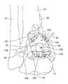
- FIG. 5illustrates one example of a surgical locator device engaging a tibia, talus, and a foreign object positioned between the tibia and talus in accordance with some embodiments.
- FIG. 6is another view of the surgical locator device engaging a tibia, talus, and a foreign object positioned between the tibia and talus in accordance with some embodiments.
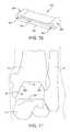
- FIG. 7illustrates one example of a cutting guide that can be positioned using pins placed by a surgical locator device in accordance with some embodiments.
- FIG. 8illustrates the cutting guide illustrated in FIG. 7 positioned against a bone using pins placed by a surgical locator device in accordance with some embodiments.
- FIG. 9illustrates one example of another cutting guide being positioned using pins placed by a surgical locator device in accordance with some embodiments.
- FIG. 10illustrates another example of another cutting guide configured to be positioned using pins placed by a surgical locator device in accordance with some embodiments.
- FIG. 11illustrates one example of a resected bone space created using cutting guides in accordance with some embodiments.
- FIG. 12is a flow diagram of one example of a method in accordance with some embodiments.
- the disclosed systems and methodsutilize custom manufactured surgical instruments, guides, and fixtures that are based upon a patient's anatomy as determined by a computer tomography scanner (CT), magnetic resonance imaging machine (MRI), or other medical imaging technology. These disclosed systems are derived from image data acquired through the medical imaging as taught by the systems and methods disclosed in U.S. Pat. No. 5,768,134 issued to Swaelens et al., commonly assigned U.S. patent application Ser. No. 12/710,898, entitled “Patient Specific Surgical Guide Locator and Mount,” and commonly assigned U.S. patent application Ser. No. 12/711,307, entitled “Method for Forming a Patient Specific Surgical Guide Mount,” the entirety of which are all incorporated by reference herein.
- the disclosed systems and methodsbuild on these disclosed systems and methods to provide the ability to perform surgical procedures beyond the initial installation of an orthopedic prosthesis.
- the disclosed systems and methodsare used to perform revision surgeries and/or fusion take-down surgeries.
- the disclosed systems and methodsutilize the imaging of one or more foreign objects in patient's body, such as a previously installed implant (including plates and screws, to list only a few possibilities), bone cement, bone graft, and/or other object not native to the patient's body, and creates surgical tools having a surface that conforms to and is complementary to a bone or cartilaginous surface and/or a surface of the one or more foreign objects.
- FIG. 1illustrates one example of a patient's ankle joint 10 comprising a tibia 12 , a talus 14 , a calcaneus 16 , and a fibula 18 .
- the ankle joint 10 illustrated in FIG. 1also includes a foreign object 50 disposed between tibia 12 and talus 14 .
- foreign object 50is illustrated as bone cement, foreign object 50 can take the form of bone graft or a previously installed orthopedic implant.
- foreign object 50includes one or more of a tibial component, talar component, stem component, plate, screw, or other component of an orthopedic prosthesis.
- the foreign object 50is described as being positioned within an ankle joint 10 , one of ordinary skill in the art will understand that the foreign object can be located in another joint including, but not limited to, a hip, knee, shoulder, elbow, and wrist, to identify only a few possible joints.
- ankle joint 10or the joint of interest, including foreign object 50 is imaged using a medical imaging technology including, but not limited to, CT and MRI, to identify only a couple of possible technologies.
- the obtained image datais converted to a 3D model of the ankle 10 , including foreign object 50 , in accordance with the methods disclosed in, for example, U.S. Pat. No. 5,768,134 issued to Swaelens et al., commonly assigned U.S. patent application Ser. No. 12/710,898, entitled “Patient Specific Surgical Guide Locator and Mount,” and commonly assigned U.S. patent application Ser. No. 12/711,307, entitled “Method for Forming a Patient Specific Surgical Guide Mount,” all of which are incorporated by reference in their entireties.
- FIG. 2illustrates one example of a surgical locator device 100 in accordance with some embodiments.
- Locator device 100includes a monolithic body 102 comprising a superior portion 104 and an inferior portion 106 .
- portions 104 and 106each respectively include approximately half of body 102 as divided about an approximate midline.
- Body 102further includes a first side 108 and a second side 110 disposed opposite first 108 as best seen in FIG. 3 .
- first side 108is a patient-engaging side and side 110 is configured to be engaged or manipulated by a user.
- superior portion 104includes a pair of arms 112 , 114 that extend away from a base 116 disposed between arms 112 , 114 as best seen in FIGS. 2 and 4 .
- Base 116includes an outwardly extending tab 118 that defines holes 120 , 122 , 124 therethrough that extend in a superior-inferior direction as best seen in FIG. 5 .
- Hole 120is disposed in a first plane
- holes 122 , 124are disposed in a second plane that is spaced apart from the first plane in a posterior direction.
- Each of holes 120 , 122 , 124is sized and configured to receive a k-wire, pin, or other elongate radiopaque object therein for reasons described in greater detail below.
- holes 122 , 124are spaced apart from one another such that collectively holes 120 , 122 , 124 are configured to form a gunsight.
- body 102defines several pairs of holes that extending in an anterior-posterior direction. For example, in some embodiments, a first pair of holes 126 disposed adjacent to an inferior edge of body 102 .
- the location of hole pair 126 relative to body 102is determined based on preoperative imaging and planning such that holes are configured to guide the insertion of k-wires, pins, or other elongate surgical instrument into talus 14 is at a specific location that corresponds to the location of holes 2104 , 2106 of talar resection guide base 2100 as disclosed in commonly assigned U.S. patent application Ser. No.
- the pair of holes 126 defined by body 102can facilitate the accurate placement of other cutting guides beyond a talar resection guide base.
- the number of holesmay be varied such that fewer than two (e.g., one) or more holes can be provided for guiding an elongate surgical device (e.g., a pin) into a bone and/or foreign object that is then used to guide another surgical instrument, such as a cutting guide, a drill guide, or a cannulated reamer, to list only a few possibilities.
- Hole pair 128is positioned superiorly relative to hole pair 126 .
- the location of hole pair 128 relative to body 102also is determined based on preoperative planning using imaging of the patient such that k-wire(s), pin(s), or other elongate surgical instrument(s) is/are inserted at a location that facilitates the placement of a surgical cutting device on the tibia 12 .
- holes 128can facilitate the placement of a tibial cutting guide such as cut guide 290 disclosed in commonly assigned U.S. patent application Ser. No.
- holes 126 defined by body 102can facilitate the accurate placement of other cutting guides, drill guides, or other surgical instruments.
- Body 102defines another pair of holes 130 , which are located along body 102 between holes 126 and holes 128 .
- Holes 130are sized and configured to receive a k-wire, pin, or other elongate surgical device therein for securing surgical locator device 100 to the joint 10 .
- body 102also defines an opening 132 between holes 130 and holes 126 as illustrated in FIGS. 2 and 4 .
- Opening 132is defined by walls 134 , 136 , 138 , 140 and extends through body 102 ( FIG. 2 ).
- opening 132provides a user of surgical locator device 100 with a viewing portal such that the user can view the underlying joint structures when surgical locator device 100 is positioned against the bone or cartilaginous structures of the joint 10 .
- the patient-engaging side 108 of locator device 100includes one or more contact surfaces that are designed to be complementary to the prominences and concavities of joint 10 , including the surface features of tibia 12 , talus 16 , and foreign object 50 .
- the superior portion 104 of patient-engaging side 108 of body 102has a first surface topography 108 a that is complementary to a distal portion of tibia 12 and, in some embodiments, a second surface topography 108 b that is complementary to a portion of foreign object 50 .
- Inferior portion 106 of patient-engaging side 108 of body 102has a third surface topography 108 c that is complementary to a portion of the talar dome or proximal portion of talus and a portion of foreign object 50 .
- FIG. 12is a flow chart of example of a method 400 in accordance with some embodiments.
- FIGS. 5-12is a flow chart of example of a method 400 in accordance with some embodiments.
- the patientis imaged.
- one or more areas of a patientcan be imaged using one or more medical imaging technologies such as x-ray, CT, and/or MRI to list only a few possibilities.
- a single joint of the patientis imaged.
- one or more images of the patient's anklecan be acquired using medical imaging instrumentation as will be understood by one of ordinary skill in the art.
- multiple joints of a patientare imaged in order to gather data concerning the patient's anatomy.
- the patient's ankle and at least one other jointe.g., knee or hip, also will be imaged.
- the image datais used to perform preoperative analysis of the surgical procedure.
- the image datais used to generate three-dimensional (3D) renderings of the patient's anatomy, which is then used by a physician to assess the implant site and the develop a surgical plan as described in commonly assigned U.S. patent application Ser. No. 12/711,307, which is incorporated by reference herein.
- the acquired image datanot only includes data concerning the patient's anatomy, such as bones and/or cartilage, but the acquired image data also includes data concerning any foreign objects 50 within the patient's body.
- the geometry and location of foreign objects 50 within the patient's bodyis used when developing the surgical plan and preoperative analysis.
- foreign object 50is bone cement used to fuse the ankle joint 10 of the patient.
- foreign object 50can be an orthopedic implant.
- one or more patient-specific surgical devicessuch as a surgical locator device 100 are fabricated.
- a surgical locator device 100is fabricated using stereolithography or selective laser sintering, to list only a couple of possible examples.
- the fabricated surgical locator device 100will be sterilized and prepared for use during surgery as will be understood by one of ordinary skill in the art.
- access to the jointis established, such as by making an incision to expose the bony and/or cartilaginous surfaces of the joint.
- the incisionis made along the anterior of the patient's ankle joint 10 to expose at least the tibia 12 , talus 14 , and foreign object 50 .
- the patient-engaging side 108 of surgical locator device 100is placed in contact with a bony surface, a cartilaginous surface, and/or in contact with a surface of foreign object 50 .
- the position of patient-engaging side 108 relative to the surface of joint 10is adjusted by the surgeon until the surgical locator device 100 “locks” to joint 10 .
- the “locking” of surgical locator device 100 to joint 10is accomplished by aligning the complementary prominences and concavities of the patient-engaging side 108 of surgical locator device 100 to the corresponding prominences and concavities of the tibia 12 , talus 14 , and foreign object 50 .
- the alignment of surgical locator device 100 relative to tibia 12is checked.
- a radiopaque elongate orthopedic device 30is inserted into hole 120 such that device 30 extends superiorly from base 116 and/or tab 118 of body 102 as shown in FIGS. 5 and 6 .
- body 102is pinned to joint 10 by inserting a k-wire or pin 32 into each of holes 130 to secure surgical locator device 100 to joint 10 during a fluoroscopic check.
- the fluoroscopic checkis performed once the surgical locator device 100 is locked to the joint 10 by imaging surgical locator device 100 to confirm the alignment of orthopedic device 100 relative to tibia 12 and/or by checking the gunsight formed by the radiopaque objects disposed within holes 120 , 122 , 124 .
- the location of surgical alignment device 100 relative to joint 10can be adjusted intraoperatively by the surgeon depending on the intraoperative fluoro checks.
- checking the alignment of a surgical locator device relative to an anatomical structure of the patient or with respect to foreign object 50does not always need to be performed.
- additional k-wires or pins 34 , 36are inserted into the tibia 12 and talus 14 through holes 126 and 128 , respectively.
- a pair of k-wires or pins 34are inserted into talus 14 by being guided by holes 126 to position the k-wires or pins 34 at a specific location in talus 14 .
- Another pair of k-wires or pins 36are inserted into tibia 12 by being guided by holes 128 at a specific location in tibia 12 .
- the locator device 100is removed from its engagement with joint 10 .
- the k-wires or pins 36 , 34received within tibia 12 and talus 14
- the k-wires or pins 32 received in holes 130are removed and body 102 of locator device 100 is slid over the k-wires or pins 34 , 36 received within holes 126 and 128 such that a pair of k-wires or pins 36 remain positioned within tibia 12 and another pair of k-wires or pins 34 remain positioned within talus 14 .
- the locator device 100is not removed from its engagement with joint 10 .
- locator device 100can be configured to include a pre-attached cutting or drill guide such that the pre-attached cutting or drill guide is positioned in the desired location relative to an anatomical structure of the patient or with respect to the foreign object 50 when locator device 10 is positioned.
- other surgical tools or devicescan be positioned relative to locator device 100 while locator device remains in its engagement with joint 10 .
- a first cutting guideis attached to one of the pairs of k-wires or pins 34 and/or 36 .
- a tibial cutting guideis positioned relative to tibia 12 by being guided by at least pins 36 .
- cutting guideis cutting guide 250 .
- cutting guide 250is positioned on tibia 12 by introducing pins 36 into holes 252 defined by cutting guide 250 and sliding cutting guide 250 along pins 36 until it contacts tibia 12 as best seen in FIG. 8 .
- the tibial cutting guidetakes other forms and engage both pins 34 and 36 .
- FIG. 9One example of such a cutting guide is illustrated in FIG. 9 .
- cutting guide 290is placed relative to tibia 12 and talus 14 by aligning pin holes 292 with pins 36 and aligning pin holes 296 with pins 34 .
- Body 294 of tibial cutting guide 290is slid along pins 34 , 36 until cutting guide 290 contacts tibia 12 and/or talus 14 .
- cutting guidescan be positioned relative to a patient's anatomy by being guided by pins 34 and/or 36 that have been placed using a surgical locator device having a patient-specific surface that is complementary not only to a patient's bony and/or cartilaginous surface, but also to a surface of a foreign body 50 disposed within a patient.
- resectionsare made using the first cutting guide.
- the cutting guide secured to a patient's bone via pins 34 and/or 36is used to guide a resecting tool, such as a bone saw.
- a resecting toolsuch as a bone saw.
- a saw or other cutting guideis inserted into slot 256 and slots 258 , which are defined by arms 254 of cutting guide 250 .
- a bone saw or other cutting deviceis inserted into slots 294 which guide cutting device as bony cuts are made to the tibia 12 .
- the cutting guidecan be configured such that cuts can be made to both the tibia 12 and talus 14 .
- the resections made using the first cutting guideincludes resecting at least a portion of foreign object 50 .
- foreign object 50may be positioned within the patient such that when a cutting device is guided by a cutting guide the cutting device makes contact with bone and a portion of foreign object 50 .
- the first cutting guide and supporting pinsare removed from the patient.
- pins 36are removed from their engagement with the tibia 12 and cutting guide 250 also is removed.
- Pins 34which do not support a cutting guide in this example, are kept in their position.
- pins 36are removed from tibia 12
- pins 34are removed from talus 14 .
- resected bone and/or resected portions or fragments of foreign object 50can also be removed from the surgical site as will be understood by one of ordinary skill in the art.
- FIG. 10illustrates one example of a talar cutting guide 300 in accordance with some embodiments.
- Talar cutting guide 300defines an elongate slot 302 that extends from a first hole 304 defined at a first end 306 to a second hole 306 defined at a second end 308 .
- Cutting guide 300is positioned by inserting pins 34 extending from talus 14 in holes 304 defined by cutting guide 300 and sliding cutting guide along pins 34 until it contacts talus 14 .
- resectionsare made using the second cutting guide.
- the cutting guide secured to a patient's bone via pins 34is used to guide a resecting tool, such as a bone saw.
- a saw or other cutting guideis inserted into slot 302 to resect talus 14 .
- the resections made using the second cutting guide 300includes resecting at least a portion of foreign object 50 .
- foreign object 50may be positioned within the patient such that when a cutting device is guided by a cutting guide the cutting device makes contact with bone and a portion of foreign object 50 .
- the second cutting guide and supporting pinsare removed from the patient, if applicable.
- pins 34can be withdrawn from talus 14 , and the pins 34 and cutting guide 300 are removed from their engagement with talus 14 .
- the resected bone and/or portion of foreign object 50also can be removed.
- FIG. 11illustrates one example of a resected bone space 80 defined by resected surfaces 12 A, 12 B, 12 C of tibia 12 , resected surface 14 A of talus 14 , and femur 18 .
- foreign object 50is not disposed within resected bone space 80 having been removed during the joint resections.
- the disclosed systems and methods described aboveadvantageously utilize medical imaging to create custom surgical tools that include surfaces that are not only complementary to a patient's bone and/or cartilaginous surface, but also to any foreign objects within the patient. These surgical tools improve the accuracy of performing revision surgeries as well as orthopedic procedures such as fusion takedowns.
- a surgical deviceincludes a body having a first side having a first surface that is complementary to a surface of a foreign object disposed within a patient based on preoperative imaging of the patient.
- the bodydefines at least one first hole positioned relative to the body to facilitate insertion of an elongate device at a predetermined location relative to the foreign object.
- the first sideincludes a second surface that is complementary to at least one of a first bone or a first cartilaginous surface of the patient.
- the first side of the bodyincludes a third surface that is complementary to at least one of a second bone or a second cartilaginous surface of the patient.
- the at least one first boneis different from the at least one second bone.
- the at least one first bone and the at least one second bonetogether define at least a portion of a joint such that the body is sized and configured to extend across at least the portion of the joint.
- the at least one holeincludes a first pair of holes, and the body defines a second pair of holes disposed at a distance from the first pair of holes.
- the second pair of holesis positioned relative to the body to facilitate insertion of a second pair of elongate devices at a second predetermined location in at least one of the second bone, the second cartilaginous surface, or the foreign object.
- the first pair of holesare defined by a superior portion of the body, and the second pair of holes are defined by an inferior portion of the body.
- the bodydefines an opening located between the first pair of holes and the second pair of holes.
- a second side of the bodyincludes a tab outwardly extending from a base.
- the tabdefines a hole therein sized and configured to receive a radiopaque object therein.
- a systemin some embodiments, includes a surgical locator device and a first guide.
- the surgical locator deviceincluding a body having a first side and a second side.
- the first side of the surgical locator deviceincluding a first surface that is complementary to a surface of a foreign object disposed within a patient based on preoperative imaging of the patient.
- the bodydefines at least one first hole positioned relative to the body to facilitate insertion of a first elongate device at a predetermined location relative to the foreign object.
- the first guidedefines at least one second hole sized and configured to receive the first elongate device therein for locating the first guide relative to the foreign object.
- the first sideincludes a second surface that is complementary to at least one of a first bone or a first cartilaginous surface of the patient.
- the first side of the body of the surgical locator deviceincludes a third surface that is complementary to at least one of a second bone or a second cartilaginous surface of the patient.
- the at least one first bone and the at least one second bonetogether define at least a portion of a joint such that the body of the surgical locator device is sized and configured to extend across at least the portion of the joint.
- the at least one first holeincludes a first part of holes
- the at least one second holeincludes a second pair of holes
- the body of the surgical locator devicedefines a third pair of holes disposed at a distance from the first pair of holes.
- the third pair of holesis positioned relative to the body of the surgical locator device to facilitate insertion of a second pair of elongate devices at a second predetermined location in at least one of the second bone, the second cartilaginous surface, or the foreign object.
- a second guidedefines a fourth pair of holes that are sized and configured to receive the second pair of elongate devices therein for locating the second guide relative to at least one of the second bone, the second cartilaginous surface, or the foreign object.
- the first pair of holesis defined by a superior portion of the body of the surgical locator device, and the third pair of holes are defined by an inferior portion of the body of the surgical locator device.
- the body of the surgical locator devicedefines an opening located between the first pair of holes and the third pair of holes.
- a second side of the bodyincludes a tab outwardly extending from a base.
- the tabdefines a hole therein sized and configured to receive a radiopaque object therein.
- a methodincludes establishing access to a joint of a patient and placing a surgical locator device in contact with the joint such that a first surface of the surgical locator device contacts at least a portion of a foreign object disposed within the patient.
- the first surface of the surgical locator deviceis complementary to the portion of the foreign object based on preoperative imaging of the patient.
- a methodincludes inserting a first pin into a first hole defined by the surgical locator device, removing the surgical locator device from its engagement with the joint of the patient, and sliding a second surgical device along the first pin to locate the second surgical device relative to the joint of the patient.
- placing the surgical locator device in contact with the jointincludes placing a second surface of the surgical locator device in contact with at least one of a portion of a first bone or a first cartilaginous surface and placing a third surface of the surgical locator device in contact with at least one of a portion of a second bone or a second cartilaginous surface of a second bone of the joint.
- the second surface of the surgical locator devicebeing complementary to the at least one of the portion of the first bone and the first cartilaginous surface based on preoperative imaging of the patient.
- the third surface of the surgical locator deviceis complementary to at least one of the portion of the second bone or the second cartilaginous surface based on preoperative imaging of the patient.
- a methodincludes inserting a third pin into a third hole defined by the surgical locator device, inserting a fourth pin into a fourth hole defined by the surgical locator device, and sliding a third surgical device along the third and fourth pins to locate the third surgical device relative to the joint of the patient.
Landscapes
- Health & Medical Sciences (AREA)
- Surgery (AREA)
- Life Sciences & Earth Sciences (AREA)
- Heart & Thoracic Surgery (AREA)
- Molecular Biology (AREA)
- Oral & Maxillofacial Surgery (AREA)
- Engineering & Computer Science (AREA)
- Biomedical Technology (AREA)
- Dentistry (AREA)
- Medical Informatics (AREA)
- Nuclear Medicine, Radiotherapy & Molecular Imaging (AREA)
- Animal Behavior & Ethology (AREA)
- General Health & Medical Sciences (AREA)
- Public Health (AREA)
- Veterinary Medicine (AREA)
- Orthopedic Medicine & Surgery (AREA)
- Surgical Instruments (AREA)
- Prostheses (AREA)
Abstract
Description
Claims (16)
Priority Applications (4)
| Application Number | Priority Date | Filing Date | Title |
|---|---|---|---|
| US16/531,469US11399850B2 (en) | 2015-03-13 | 2019-08-05 | Patient-specific surgical devices, systems, and methods |
| US17/808,752US11826063B2 (en) | 2015-03-13 | 2022-06-24 | Patient-specific surgical devices, system, and methods |
| US18/490,930US12121248B2 (en) | 2015-03-13 | 2023-10-20 | Patient-specific surgical devices, system, and methods |
| US18/891,140US20250009369A1 (en) | 2015-03-13 | 2024-09-20 | Patient-specific surgical devices, system, and methods |
Applications Claiming Priority (1)
| Application Number | Priority Date | Filing Date | Title |
|---|---|---|---|
| PCT/US2015/020414WO2016148675A1 (en) | 2015-03-13 | 2015-03-13 | Patient-specific surgical devices, systems, and methods |
Related Parent Applications (1)
| Application Number | Title | Priority Date | Filing Date |
|---|---|---|---|
| PCT/US2015/020414A-371-Of-InternationalWO2016148675A1 (en) | 2015-03-13 | 2015-03-13 | Patient-specific surgical devices, systems, and methods |
Related Child Applications (1)
| Application Number | Title | Priority Date | Filing Date |
|---|---|---|---|
| US16/531,469ContinuationUS11399850B2 (en) | 2015-03-13 | 2019-08-05 | Patient-specific surgical devices, systems, and methods |
Publications (2)
| Publication Number | Publication Date |
|---|---|
| US20180177513A1 US20180177513A1 (en) | 2018-06-28 |
| US10413308B2true US10413308B2 (en) | 2019-09-17 |
Family
ID=56896873
Family Applications (5)
| Application Number | Title | Priority Date | Filing Date |
|---|---|---|---|
| US14/442,595ActiveUS10413308B2 (en) | 2015-03-13 | 2015-03-13 | Patient-specific surgical devices, systems, and methods |
| US16/531,469Active2036-01-05US11399850B2 (en) | 2015-03-13 | 2019-08-05 | Patient-specific surgical devices, systems, and methods |
| US17/808,752ActiveUS11826063B2 (en) | 2015-03-13 | 2022-06-24 | Patient-specific surgical devices, system, and methods |
| US18/490,930ActiveUS12121248B2 (en) | 2015-03-13 | 2023-10-20 | Patient-specific surgical devices, system, and methods |
| US18/891,140PendingUS20250009369A1 (en) | 2015-03-13 | 2024-09-20 | Patient-specific surgical devices, system, and methods |
Family Applications After (4)
| Application Number | Title | Priority Date | Filing Date |
|---|---|---|---|
| US16/531,469Active2036-01-05US11399850B2 (en) | 2015-03-13 | 2019-08-05 | Patient-specific surgical devices, systems, and methods |
| US17/808,752ActiveUS11826063B2 (en) | 2015-03-13 | 2022-06-24 | Patient-specific surgical devices, system, and methods |
| US18/490,930ActiveUS12121248B2 (en) | 2015-03-13 | 2023-10-20 | Patient-specific surgical devices, system, and methods |
| US18/891,140PendingUS20250009369A1 (en) | 2015-03-13 | 2024-09-20 | Patient-specific surgical devices, system, and methods |
Country Status (8)
| Country | Link |
|---|---|
| US (5) | US10413308B2 (en) |
| EP (1) | EP3267911A4 (en) |
| JP (1) | JP6286563B2 (en) |
| CN (2) | CN106456190B (en) |
| AU (5) | AU2015202252B2 (en) |
| BR (1) | BR112017001156A2 (en) |
| CA (2) | CA2896958C (en) |
| WO (1) | WO2016148675A1 (en) |
Cited By (8)
| Publication number | Priority date | Publication date | Assignee | Title |
|---|---|---|---|---|
| US20220323086A1 (en)* | 2015-03-13 | 2022-10-13 | Wright Medical Technology, Inc. | Patient-specific surgical devices, system, and methods |
| EP4091554A2 (en) | 2021-05-20 | 2022-11-23 | Wright Medical Technology, Inc. | Multi-modal patient-specific surgical guides |
| EP4275624A2 (en) | 2022-05-13 | 2023-11-15 | Wright Medical Technology, Inc. | Intraoperative adjustable guides and systems |
| US20230389937A1 (en)* | 2021-02-05 | 2023-12-07 | Wright Medical Technology, Inc. | Surgical guide with cutting depth information |
| US11974762B1 (en)* | 2018-02-08 | 2024-05-07 | Lento Medical Inc. | Patient-specific, mechanical self-locking, femoral and tibial surgical cutting jigs |
| US12108959B2 (en) | 2019-05-29 | 2024-10-08 | Wright Medical Technology, Inc. | Preparing a tibia for receiving tibial implant component of a replacement ankle |
| US12396739B2 (en) | 2020-01-17 | 2025-08-26 | Wright Medical Technology, Inc. | Guidance tools, systems, and methods |
| US12440227B2 (en) | 2022-01-05 | 2025-10-14 | Wright Medical Technology, Inc. | Preparing a tibia for receiving tibial implant component of a replacement ankle |
Families Citing this family (40)
| Publication number | Priority date | Publication date | Assignee | Title |
|---|---|---|---|---|
| US10758283B2 (en) | 2016-08-11 | 2020-09-01 | Mighty Oak Medical, Inc. | Fixation devices having fenestrations and methods for using the same |
| US12357413B2 (en) | 2010-06-29 | 2025-07-15 | Mighty Oak Medical, Inc. | Patient-matched apparatus for use in spine related surgical procedures and methods for using the same |
| US11039889B2 (en) | 2010-06-29 | 2021-06-22 | Mighty Oak Medical, Inc. | Patient-matched apparatus and methods for performing surgical procedures |
| US11806197B2 (en) | 2010-06-29 | 2023-11-07 | Mighty Oak Medical, Inc. | Patient-matched apparatus for use in spine related surgical procedures and methods for using the same |
| US11376073B2 (en) | 2010-06-29 | 2022-07-05 | Mighty Oak Medical Inc. | Patient-matched apparatus and methods for performing surgical procedures |
| FR3010628B1 (en) | 2013-09-18 | 2015-10-16 | Medicrea International | METHOD FOR REALIZING THE IDEAL CURVATURE OF A ROD OF A VERTEBRAL OSTEOSYNTHESIS EQUIPMENT FOR STRENGTHENING THE VERTEBRAL COLUMN OF A PATIENT |
| FR3012030B1 (en) | 2013-10-18 | 2015-12-25 | Medicrea International | METHOD FOR REALIZING THE IDEAL CURVATURE OF A ROD OF A VERTEBRAL OSTEOSYNTHESIS EQUIPMENT FOR STRENGTHENING THE VERTEBRAL COLUMN OF A PATIENT |
| WO2016028270A1 (en)* | 2014-08-19 | 2016-02-25 | Wright Medical Technology, Inc. | Geared instrument for tibial stem reaming or removal |
| US10456211B2 (en) | 2015-11-04 | 2019-10-29 | Medicrea International | Methods and apparatus for spinal reconstructive surgery and measuring spinal length and intervertebral spacing, tension and rotation |
| US10743890B2 (en) | 2016-08-11 | 2020-08-18 | Mighty Oak Medical, Inc. | Drill apparatus and surgical fixation devices and methods for using the same |
| US12016573B2 (en) | 2016-08-11 | 2024-06-25 | Mighty Oak Medical, Inc. | Drill apparatus and surgical fixation devices and methods for using the same |
| WO2018109556A1 (en) | 2016-12-12 | 2018-06-21 | Medicrea International | Systems and methods for patient-specific spinal implants |
| EP3612122B1 (en) | 2017-04-21 | 2023-12-20 | Medicrea International | A system for developing one or more patient-specific spinal implants |
| WO2019091537A1 (en)* | 2017-11-13 | 2019-05-16 | Hafez Mahmoud Alm El Din | A three-in-one patient-specific template for usage in ankle replacement surgeries |
| US10918422B2 (en) | 2017-12-01 | 2021-02-16 | Medicrea International | Method and apparatus for inhibiting proximal junctional failure |
| USD948717S1 (en) | 2018-06-04 | 2022-04-12 | Mighty Oak Medical, Inc. | Sacro-iliac guide |
| CN112955091B (en)* | 2018-10-26 | 2024-09-17 | 尤里卡发明有限公司 | Surgical devices and methods |
| US12295628B2 (en) | 2018-11-01 | 2025-05-13 | Howmedica Osteonics Corp. | Device for fixating orthopedic injury |
| EP3893765A4 (en) | 2018-12-13 | 2023-03-29 | Paragon 28, Inc. | Total ankle replacement surgical method |
| WO2020124055A1 (en) | 2018-12-13 | 2020-06-18 | Paragon 28, Inc. | Joint replacement alignment guides, systems and methods of use and assembly |
| EP3893772A4 (en) | 2018-12-13 | 2022-11-23 | Paragon 28, Inc. | RESECTION GUIDES, SCAN REAMERS AND METHODS FOR USE IN TOTAL ANKLE REPLACEMENT |
| WO2020123899A1 (en) | 2018-12-13 | 2020-06-18 | Paragon 28, Inc. | Alignment instruments and methods for use in total ankle replacement |
| AU2019398470B2 (en) | 2018-12-13 | 2025-09-25 | Paragon 28, Inc. | Distractors having attachable paddles, impaction devices, and methods for use in total ankle replacement |
| WO2020124052A1 (en) | 2018-12-13 | 2020-06-18 | Paragon 28, Inc. | Instruments, guides and related methods for total ankle replacement |
| JP7487222B2 (en) | 2019-03-26 | 2024-05-20 | マイティ オーク メディカル、インコーポレイテッド | Patient-adapted device for use in augmented reality assisted surgery and method for using same - Patents.com |
| US11925417B2 (en) | 2019-04-02 | 2024-03-12 | Medicrea International | Systems, methods, and devices for developing patient-specific spinal implants, treatments, operations, and/or procedures |
| US11877801B2 (en) | 2019-04-02 | 2024-01-23 | Medicrea International | Systems, methods, and devices for developing patient-specific spinal implants, treatments, operations, and/or procedures |
| US11944385B2 (en) | 2019-04-02 | 2024-04-02 | Medicrea International | Systems and methods for medical image analysis |
| US11986251B2 (en) | 2019-09-13 | 2024-05-21 | Treace Medical Concepts, Inc. | Patient-specific osteotomy instrumentation |
| EP4027922A4 (en) | 2019-09-13 | 2023-10-04 | MIOS Marketing LLC, DBA RedPoint Medical 3D | Patient-specific surgical methods and instrumentation |
| GB2589960B (en) | 2019-09-16 | 2023-09-20 | Nextremity Solutions Inc | Bone cut guide apparatus |
| EP4044940A4 (en) | 2019-10-18 | 2023-11-01 | Orthosoft ULC | PATIENT-SPECIFIC INSTRUMENTS AND PROCEDURES FOR ARTHROPLASTY OF THE ANKLE JOINT |
| US11769251B2 (en) | 2019-12-26 | 2023-09-26 | Medicrea International | Systems and methods for medical image analysis |
| CN111956296A (en)* | 2020-07-10 | 2020-11-20 | 嘉思特华剑医疗器材(天津)有限公司 | Internal and external ankle positioning module for tibial high-position osteotomy surgical guide plate |
| US20230310012A1 (en)* | 2020-11-02 | 2023-10-05 | Wright Medical Technology, Inc. | Modular guide system for surgical procedures |
| US12364524B2 (en)* | 2020-12-10 | 2025-07-22 | Tyber Medical Llc | Extremity fusion plate assembly |
| US12324597B2 (en)* | 2021-02-23 | 2025-06-10 | 3D-Side | Methods and systems for arthroplasty |
| USD992114S1 (en) | 2021-08-12 | 2023-07-11 | Mighty Oak Medical, Inc. | Surgical guide |
| US12433532B2 (en) | 2022-06-02 | 2025-10-07 | Wright Medical Technology, Inc. | Flexion/extension surgical guides and methods of using the same |
| CN115444497B (en)* | 2022-09-20 | 2025-06-27 | 宽岳医疗器材(苏州)有限公司 | Ankle joint osteotomy guide plate assembly |
Citations (22)
| Publication number | Priority date | Publication date | Assignee | Title |
|---|---|---|---|---|
| US5423827A (en) | 1994-06-02 | 1995-06-13 | Intermedics Orthopedics, Inc. | Surgical jig for femoral knee prosthesis |
| US5768134A (en) | 1994-04-19 | 1998-06-16 | Materialise, Naamloze Vennootschap | Method for making a perfected medical model on the basis of digital image information of a part of the body |
| WO2009045960A1 (en) | 2007-09-30 | 2009-04-09 | Depuy Products, Inc. | Customized patient-specific orthopaedic surgical instrumentation |
| US20100212138A1 (en) | 2009-02-24 | 2010-08-26 | Wright Medical Technology, Inc. | Method For Forming A Patient Specific Surgical Guide Mount |
| US20100262150A1 (en)* | 2009-04-13 | 2010-10-14 | George John Lian | Custom radiographically designed cutting guides and instruments for use in total ankle replacement surgery |
| US20110015636A1 (en)* | 2006-02-27 | 2011-01-20 | Biomet Manufacturing Corp. | Patient-Specific Elbow Guides and Associated Methods |
| WO2011018458A1 (en) | 2009-08-13 | 2011-02-17 | Luis Schuster | Device for the resection of bones, method for producing such a device, endoprosthesis suited for this purpose and method for producing such an endoprosthesis |
| US20110319745A1 (en) | 2010-06-29 | 2011-12-29 | Frey George A | Patient Matching Surgical Guide and Method for Using the Same |
| WO2012024306A2 (en) | 2010-08-16 | 2012-02-23 | Aashiish Agnihotri | Surgical guides |
| CN102458269A (en) | 2009-06-24 | 2012-05-16 | 定制Med整形(私人)有限公司 | Positioning guide and femur bone cutting guide system |
| US20120130434A1 (en) | 2009-02-24 | 2012-05-24 | Wright Medical Technology, Inc. | Orthopedic surgical guide |
| US20120239045A1 (en)* | 2011-03-17 | 2012-09-20 | Zimmer, Inc. | Patient-specific instruments for total ankle arthroplasty |
| WO2013025814A1 (en) | 2011-08-15 | 2013-02-21 | Conformis, Inc. | Revision systems, tools and methods for revising joint arthroplasty implants |
| WO2013169475A1 (en) | 2012-05-08 | 2013-11-14 | Neal David J | Porous spacers, instruments, and methods for foot and ankle fusion |
| WO2014020561A1 (en) | 2012-08-01 | 2014-02-06 | Custom Med Orthopaedics Proprietary Limited | A surgical tool guide |
| WO2014026084A1 (en) | 2012-08-09 | 2014-02-13 | Smith & Nephew, Inc. | Intraoperatively adjusting guide alignment |
| US20140163563A1 (en) | 2012-12-12 | 2014-06-12 | Wright Medical Technology, Inc. | Instrument for intra-operative implant templating using fluoroscopy |
| US20140163570A1 (en) | 2012-12-12 | 2014-06-12 | Wright Medical Technology, Inc. | Alignment guide with embedded features for intra-operative fluoro-checks |
| CA2836651A1 (en) | 2012-12-27 | 2014-06-27 | Wright Medical Technology, Inc. | Ankle replacement system and method |
| US8808297B2 (en) | 2009-02-24 | 2014-08-19 | Microport Orthopedics Holdings Inc. | Orthopedic surgical guide |
| US20140257309A1 (en)* | 2013-03-11 | 2014-09-11 | Luke J. Aram | Customized patient-specific revision surgical instruments and method |
| US20140336658A1 (en) | 2012-12-27 | 2014-11-13 | Wright Medical Technology, Inc. | Ankle replacement system and method |
Family Cites Families (10)
| Publication number | Priority date | Publication date | Assignee | Title |
|---|---|---|---|---|
| US9539044B2 (en)* | 2009-04-13 | 2017-01-10 | George John Lian | Systems and instrumentalities for use in removal of tibial prostheses of total ankle replacements |
| US8475463B2 (en)* | 2009-04-13 | 2013-07-02 | George J. Lian | Systems and instrumentalities for use in total ankle replacement surgery |
| US9138247B2 (en)* | 2012-05-04 | 2015-09-22 | DePuy Synthes Products, Inc. | Customized patient-specific orthopaedic pin guides |
| GB2504124A (en)* | 2012-07-20 | 2014-01-22 | Ibm | Managing concurrent conversations over a communications link between a client computer and a server computer |
| WO2014020562A1 (en)* | 2012-08-01 | 2014-02-06 | Custom Med Orthopaedics Proprietary Limited | A surgical tool guide |
| US9974588B2 (en)* | 2012-12-27 | 2018-05-22 | Wright Medical Technology, Inc. | Ankle replacement system and method |
| US9949839B2 (en)* | 2013-03-13 | 2018-04-24 | Wright Medical Technology, Inc. | Revision implant augments, systems, and methods |
| JP6259513B2 (en) | 2013-06-07 | 2018-01-10 | フライ, ジョージFREY, George | Patient-compatible instruments and methods for performing surgical procedures |
| CA2896958C (en)* | 2015-03-13 | 2017-10-24 | Wright Medical Technology, Inc. | Patient-specific surgical devices, systems, and methods |
| WO2021146015A1 (en)* | 2020-01-17 | 2021-07-22 | Wright Medical Technology, Inc. | Guidance tools, systems, and methods |
- 2015
- 2015-03-13CACA2896958Apatent/CA2896958C/enactiveActive
- 2015-03-13JPJP2016544422Apatent/JP6286563B2/enactiveActive
- 2015-03-13WOPCT/US2015/020414patent/WO2016148675A1/ennot_activeCeased
- 2015-03-13BRBR112017001156Apatent/BR112017001156A2/ennot_activeApplication Discontinuation
- 2015-03-13USUS14/442,595patent/US10413308B2/enactiveActive
- 2015-03-13AUAU2015202252Apatent/AU2015202252B2/enactiveActive
- 2015-03-13CNCN201580001470.2Apatent/CN106456190B/enactiveActive
- 2015-03-13EPEP15721110.3Apatent/EP3267911A4/enactivePending
- 2015-03-13CACA2981340Apatent/CA2981340C/enactiveActive
- 2015-03-13CNCN202010526142.7Apatent/CN111643148A/enactivePending
- 2017
- 2017-08-31AUAU2017221820Apatent/AU2017221820B2/enactiveActive
- 2019
- 2019-08-05USUS16/531,469patent/US11399850B2/enactiveActive
- 2019-10-18AUAU2019250241Apatent/AU2019250241B2/enactiveActive
- 2020
- 2020-10-29AUAU2020260459Apatent/AU2020260459B2/enactiveActive
- 2021
- 2021-12-22AUAU2021290278Apatent/AU2021290278A1/ennot_activeAbandoned
- 2022
- 2022-06-24USUS17/808,752patent/US11826063B2/enactiveActive
- 2023
- 2023-10-20USUS18/490,930patent/US12121248B2/enactiveActive
- 2024
- 2024-09-20USUS18/891,140patent/US20250009369A1/enactivePending
Patent Citations (35)
| Publication number | Priority date | Publication date | Assignee | Title |
|---|---|---|---|---|
| US5768134A (en) | 1994-04-19 | 1998-06-16 | Materialise, Naamloze Vennootschap | Method for making a perfected medical model on the basis of digital image information of a part of the body |
| US5423827A (en) | 1994-06-02 | 1995-06-13 | Intermedics Orthopedics, Inc. | Surgical jig for femoral knee prosthesis |
| US20110015636A1 (en)* | 2006-02-27 | 2011-01-20 | Biomet Manufacturing Corp. | Patient-Specific Elbow Guides and Associated Methods |
| US8377066B2 (en)* | 2006-02-27 | 2013-02-19 | Biomet Manufacturing Corp. | Patient-specific elbow guides and associated methods |
| WO2009045960A1 (en) | 2007-09-30 | 2009-04-09 | Depuy Products, Inc. | Customized patient-specific orthopaedic surgical instrumentation |
| US20120130434A1 (en) | 2009-02-24 | 2012-05-24 | Wright Medical Technology, Inc. | Orthopedic surgical guide |
| US20100212138A1 (en) | 2009-02-24 | 2010-08-26 | Wright Medical Technology, Inc. | Method For Forming A Patient Specific Surgical Guide Mount |
| US20100217338A1 (en) | 2009-02-24 | 2010-08-26 | Wright Medical Technology, Inc. | Patient Specific Surgical Guide Locator and Mount |
| US8808303B2 (en) | 2009-02-24 | 2014-08-19 | Microport Orthopedics Holdings Inc. | Orthopedic surgical guide |
| US8808297B2 (en) | 2009-02-24 | 2014-08-19 | Microport Orthopedics Holdings Inc. | Orthopedic surgical guide |
| US9017334B2 (en) | 2009-02-24 | 2015-04-28 | Microport Orthopedics Holdings Inc. | Patient specific surgical guide locator and mount |
| US20100262150A1 (en)* | 2009-04-13 | 2010-10-14 | George John Lian | Custom radiographically designed cutting guides and instruments for use in total ankle replacement surgery |
| US8337503B2 (en) | 2009-04-13 | 2012-12-25 | George John Lian | Custom radiographically designed cutting guides and instruments for use in total ankle replacement surgery |
| US20120123420A1 (en) | 2009-06-24 | 2012-05-17 | John Robert Honiball | Positioning guide and bone cutting guide system |
| CN102458269A (en) | 2009-06-24 | 2012-05-16 | 定制Med整形(私人)有限公司 | Positioning guide and femur bone cutting guide system |
| US20160296240A1 (en) | 2009-08-13 | 2016-10-13 | Biomet Manufacturing, Llc | Device for the resection of bones, method for producing such a device, endoprosthesis suited for this purpose and method for producing such an endoprosthesis |
| WO2011018458A1 (en) | 2009-08-13 | 2011-02-17 | Luis Schuster | Device for the resection of bones, method for producing such a device, endoprosthesis suited for this purpose and method for producing such an endoprosthesis |
| CN103096819A (en) | 2010-06-29 | 2013-05-08 | 乔治·弗雷 | Patient-matched surgical guide and method of use thereof |
| US20110319745A1 (en) | 2010-06-29 | 2011-12-29 | Frey George A | Patient Matching Surgical Guide and Method for Using the Same |
| WO2012024306A2 (en) | 2010-08-16 | 2012-02-23 | Aashiish Agnihotri | Surgical guides |
| US20120239045A1 (en)* | 2011-03-17 | 2012-09-20 | Zimmer, Inc. | Patient-specific instruments for total ankle arthroplasty |
| WO2013025814A1 (en) | 2011-08-15 | 2013-02-21 | Conformis, Inc. | Revision systems, tools and methods for revising joint arthroplasty implants |
| CN103841924A (en) | 2011-08-15 | 2014-06-04 | 康复米斯公司 | Revision systems, tools and methods for revising joint arthroplasty implants |
| JP2014531920A (en) | 2011-08-15 | 2014-12-04 | コンフォーミス・インコーポレイテッドConforMIS, Inc. | Revision system, tool, and method for revision of an arthroplasty implant |
| WO2013169475A1 (en) | 2012-05-08 | 2013-11-14 | Neal David J | Porous spacers, instruments, and methods for foot and ankle fusion |
| WO2014020561A1 (en) | 2012-08-01 | 2014-02-06 | Custom Med Orthopaedics Proprietary Limited | A surgical tool guide |
| WO2014026084A1 (en) | 2012-08-09 | 2014-02-13 | Smith & Nephew, Inc. | Intraoperatively adjusting guide alignment |
| EP2742878A1 (en) | 2012-12-12 | 2014-06-18 | Wright Medical Technology, Inc. | Alignment guide with embedded features for intra-operative fluoro-checks |
| JP2014131724A (en) | 2012-12-12 | 2014-07-17 | Wright Medical Technology Inc | Alignment guide with shape for intra-operation fluoroscopic examination |
| US20140163563A1 (en) | 2012-12-12 | 2014-06-12 | Wright Medical Technology, Inc. | Instrument for intra-operative implant templating using fluoroscopy |
| CN103860244A (en) | 2012-12-12 | 2014-06-18 | 瑞特医疗技术公司 | Alignment guide with embedded features for intra-operative fluoro-checks |
| US20140163570A1 (en) | 2012-12-12 | 2014-06-12 | Wright Medical Technology, Inc. | Alignment guide with embedded features for intra-operative fluoro-checks |
| CA2836651A1 (en) | 2012-12-27 | 2014-06-27 | Wright Medical Technology, Inc. | Ankle replacement system and method |
| US20140336658A1 (en) | 2012-12-27 | 2014-11-13 | Wright Medical Technology, Inc. | Ankle replacement system and method |
| US20140257309A1 (en)* | 2013-03-11 | 2014-09-11 | Luke J. Aram | Customized patient-specific revision surgical instruments and method |
Non-Patent Citations (9)
| Title |
|---|
| Examination Report issued in corresponding Australian patent application No. 2015202252, dated May 11, 2016, 6 pages. |
| Examination Report issued in corresponding Australian Patent Application No. 2017221820, dated Sep. 13, 2018, 4 pages. |
| First Office Action issued for corresponding Japanese patent application No. 2016-544422, dated May 16, 2017, 3 pages. |
| International Search Report and Written Opinion of the International Searching Authority issued in connection with International Patent Application No. PCT/US2015/020414, 12 pages. |
| Office Action issued in connection with corresponding Canadian patent application No. 2,896,958, dated May 25, 2016, 4 pages. |
| Office Action issued in corresponding Chinese Patent Application No. 201580001470.2, dated Jul. 30, 2018, 8 pages. |
| Second Office Action issued in corresponding Chinese Patent Application No. 201580001470.2, dated Jun. 4, 2019, 9 pages. |
| Supplementary Partial European Search Report issued in corresponding European Patent Application No. 15721110, dated Mar. 19, 2019, 10 pages. |
| Web Site: Total Ankle Institute, "Prophecy Inbone", Nov. 1, 2014 (tracked by waybackmachine) http://www.totalankleinstitute.com/INBONE/-Products/PROPHECY-INBONE) 5 pages. |
Cited By (11)
| Publication number | Priority date | Publication date | Assignee | Title |
|---|---|---|---|---|
| US20220323086A1 (en)* | 2015-03-13 | 2022-10-13 | Wright Medical Technology, Inc. | Patient-specific surgical devices, system, and methods |
| US11826063B2 (en)* | 2015-03-13 | 2023-11-28 | Wright Medical Technology, Inc. | Patient-specific surgical devices, system, and methods |
| US20240041479A1 (en)* | 2015-03-13 | 2024-02-08 | Wright Medical Technology, Inc. | Patient-specific surgical devices, system, and methods |
| US12121248B2 (en)* | 2015-03-13 | 2024-10-22 | Wright Medical Technology, Inc. | Patient-specific surgical devices, system, and methods |
| US11974762B1 (en)* | 2018-02-08 | 2024-05-07 | Lento Medical Inc. | Patient-specific, mechanical self-locking, femoral and tibial surgical cutting jigs |
| US12108959B2 (en) | 2019-05-29 | 2024-10-08 | Wright Medical Technology, Inc. | Preparing a tibia for receiving tibial implant component of a replacement ankle |
| US12396739B2 (en) | 2020-01-17 | 2025-08-26 | Wright Medical Technology, Inc. | Guidance tools, systems, and methods |
| US20230389937A1 (en)* | 2021-02-05 | 2023-12-07 | Wright Medical Technology, Inc. | Surgical guide with cutting depth information |
| EP4091554A2 (en) | 2021-05-20 | 2022-11-23 | Wright Medical Technology, Inc. | Multi-modal patient-specific surgical guides |
| US12440227B2 (en) | 2022-01-05 | 2025-10-14 | Wright Medical Technology, Inc. | Preparing a tibia for receiving tibial implant component of a replacement ankle |
| EP4275624A2 (en) | 2022-05-13 | 2023-11-15 | Wright Medical Technology, Inc. | Intraoperative adjustable guides and systems |
Also Published As
| Publication number | Publication date |
|---|---|
| JP6286563B2 (en) | 2018-02-28 |
| US20180177513A1 (en) | 2018-06-28 |
| CN106456190B (en) | 2020-06-26 |
| CA2896958C (en) | 2017-10-24 |
| AU2020260459B2 (en) | 2021-09-23 |
| BR112017001156A2 (en) | 2018-01-30 |
| WO2016148675A1 (en) | 2016-09-22 |
| AU2021290278A1 (en) | 2022-01-27 |
| CA2981340A1 (en) | 2016-09-13 |
| EP3267911A4 (en) | 2019-04-17 |
| US20190350602A1 (en) | 2019-11-21 |
| CA2896958A1 (en) | 2016-09-13 |
| US20220323086A1 (en) | 2022-10-13 |
| EP3267911A1 (en) | 2018-01-17 |
| US20250009369A1 (en) | 2025-01-09 |
| AU2015202252B2 (en) | 2017-06-01 |
| CN106456190A (en) | 2017-02-22 |
| AU2019250241A1 (en) | 2019-11-07 |
| JP2017511160A (en) | 2017-04-20 |
| US11399850B2 (en) | 2022-08-02 |
| US12121248B2 (en) | 2024-10-22 |
| AU2017221820A1 (en) | 2017-09-21 |
| US20240041479A1 (en) | 2024-02-08 |
| AU2017221820B2 (en) | 2019-09-26 |
| CA2981340C (en) | 2022-04-12 |
| CN111643148A (en) | 2020-09-11 |
| AU2019250241B2 (en) | 2020-08-06 |
| AU2020260459A1 (en) | 2020-11-26 |
| US11826063B2 (en) | 2023-11-28 |
| AU2015202252A1 (en) | 2016-09-29 |
Similar Documents
| Publication | Publication Date | Title |
|---|---|---|
| US12121248B2 (en) | Patient-specific surgical devices, system, and methods | |
| US11779356B2 (en) | Orthopedic surgical guide | |
| EP2742878B1 (en) | Alignment guide with embedded features for intra-operative fluoro-checks | |
| AU2019261830A1 (en) | Orthopedic surgical guide | |
| US20220370083A1 (en) | Multi-modal patient-specific surgical guides | |
| AU2014253567A1 (en) | Orthopedic surgical guide |
Legal Events
| Date | Code | Title | Description |
|---|---|---|---|
| AS | Assignment | Owner name:WRIGHT MEDICAL TECHNOLOGY, INC., TENNESSEE Free format text:ASSIGNMENT OF ASSIGNORS INTEREST;ASSIGNORS:STEMNISKI, PAUL M.;REYNOLDS, DAVID G.;REEL/FRAME:035165/0152 Effective date:20150313 | |
| AS | Assignment | Owner name:WRIGHT MEDICAL TECHNOLOGY, INC., TENNESSEE Free format text:ASSIGNMENT OF ASSIGNORS INTEREST;ASSIGNORS:STEMNISKI, PAUL M.;REYNOLDS, DAVID G.;REEL/FRAME:035756/0183 Effective date:20150313 | |
| AS | Assignment | Owner name:MIDCAP FINANCIAL TRUST, AS AGENT, MARYLAND Free format text:SECURITY INTEREST;ASSIGNOR:WRIGHT MEDICAL TECHNOLOGY, INC.;REEL/FRAME:041257/0126 Effective date:20161223 | |
| STPP | Information on status: patent application and granting procedure in general | Free format text:FINAL REJECTION MAILED | |
| STPP | Information on status: patent application and granting procedure in general | Free format text:RESPONSE AFTER FINAL ACTION FORWARDED TO EXAMINER | |
| STPP | Information on status: patent application and granting procedure in general | Free format text:NOTICE OF ALLOWANCE MAILED -- APPLICATION RECEIVED IN OFFICE OF PUBLICATIONS | |
| STPP | Information on status: patent application and granting procedure in general | Free format text:PUBLICATIONS -- ISSUE FEE PAYMENT VERIFIED | |
| STCF | Information on status: patent grant | Free format text:PATENTED CASE | |
| AS | Assignment | Owner name:WRIGHT MEDICAL GROUP N.V., NETHERLANDS Free format text:RELEASE BY SECURED PARTY;ASSIGNOR:MIDCAP FUNDING IV TRUST;REEL/FRAME:054480/0001 Effective date:20201112 Owner name:WHITE BOX ORTHOPEDICS, LLC, TENNESSEE Free format text:RELEASE BY SECURED PARTY;ASSIGNOR:MIDCAP FUNDING IV TRUST;REEL/FRAME:054480/0001 Effective date:20201112 Owner name:WRIGHT MEDICAL GROUP, INC., TENNESSEE Free format text:RELEASE BY SECURED PARTY;ASSIGNOR:MIDCAP FUNDING IV TRUST;REEL/FRAME:054480/0001 Effective date:20201112 Owner name:SOLANA SURGICAL, LLC, TENNESSEE Free format text:RELEASE BY SECURED PARTY;ASSIGNOR:MIDCAP FUNDING IV TRUST;REEL/FRAME:054480/0001 Effective date:20201112 Owner name:WRIGHT MEDICAL GROUP INTELLECTUAL PROPERTY, INC., TENNESSEE Free format text:RELEASE BY SECURED PARTY;ASSIGNOR:MIDCAP FUNDING IV TRUST;REEL/FRAME:054480/0001 Effective date:20201112 Owner name:BIOMIMETIC THERAPEUTICS USA, INC., TENNESSEE Free format text:RELEASE BY SECURED PARTY;ASSIGNOR:MIDCAP FUNDING IV TRUST;REEL/FRAME:054480/0001 Effective date:20201112 Owner name:BIOMIMETIC THERAPEUTICS CANADA, INC., TENNESSEE Free format text:RELEASE BY SECURED PARTY;ASSIGNOR:MIDCAP FUNDING IV TRUST;REEL/FRAME:054480/0001 Effective date:20201112 Owner name:ORTHOPRO, L.L.C., TENNESSEE Free format text:RELEASE BY SECURED PARTY;ASSIGNOR:MIDCAP FUNDING IV TRUST;REEL/FRAME:054480/0001 Effective date:20201112 Owner name:ORTHOHELIX SURGICAL DESIGNS, INC., MINNESOTA Free format text:RELEASE BY SECURED PARTY;ASSIGNOR:MIDCAP FUNDING IV TRUST;REEL/FRAME:054480/0001 Effective date:20201112 Owner name:TROOPER HOLDINGS INC., MINNESOTA Free format text:RELEASE BY SECURED PARTY;ASSIGNOR:MIDCAP FUNDING IV TRUST;REEL/FRAME:054480/0001 Effective date:20201112 Owner name:BIOMIMETIC THERAPEUTICS, LLC, TENNESSEE Free format text:RELEASE BY SECURED PARTY;ASSIGNOR:MIDCAP FUNDING IV TRUST;REEL/FRAME:054480/0001 Effective date:20201112 Owner name:TORNIER, INC., MINNESOTA Free format text:RELEASE BY SECURED PARTY;ASSIGNOR:MIDCAP FUNDING IV TRUST;REEL/FRAME:054480/0001 Effective date:20201112 Owner name:INBONE TECHNOLOGIES, INC., TENNESSEE Free format text:RELEASE BY SECURED PARTY;ASSIGNOR:MIDCAP FUNDING IV TRUST;REEL/FRAME:054480/0001 Effective date:20201112 Owner name:TORNIER US HOLDINGS, INC., MINNESOTA Free format text:RELEASE BY SECURED PARTY;ASSIGNOR:MIDCAP FUNDING IV TRUST;REEL/FRAME:054480/0001 Effective date:20201112 Owner name:WRIGHT MEDICAL TECHNOLOGY, INC., TENNESSEE Free format text:RELEASE BY SECURED PARTY;ASSIGNOR:MIDCAP FUNDING IV TRUST;REEL/FRAME:054480/0001 Effective date:20201112 Owner name:WRIGHT MEDICAL CAPITAL, INC., TENNESSEE Free format text:RELEASE BY SECURED PARTY;ASSIGNOR:MIDCAP FUNDING IV TRUST;REEL/FRAME:054480/0001 Effective date:20201112 | |
| MAFP | Maintenance fee payment | Free format text:PAYMENT OF MAINTENANCE FEE, 4TH YEAR, LARGE ENTITY (ORIGINAL EVENT CODE: M1551); ENTITY STATUS OF PATENT OWNER: LARGE ENTITY Year of fee payment:4 |