US10412700B2 - Portable-device-locating system that uses room-level motion sensors and RSSI measurements to determine precise room-location - Google Patents
Portable-device-locating system that uses room-level motion sensors and RSSI measurements to determine precise room-locationDownload PDFInfo
- Publication number
- US10412700B2 US10412700B2US16/214,979US201816214979AUS10412700B2US 10412700 B2US10412700 B2US 10412700B2US 201816214979 AUS201816214979 AUS 201816214979AUS 10412700 B2US10412700 B2US 10412700B2
- Authority
- US
- United States
- Prior art keywords
- room
- beacon
- motion
- location
- portable device
- Prior art date
- Legal status (The legal status is an assumption and is not a legal conclusion. Google has not performed a legal analysis and makes no representation as to the accuracy of the status listed.)
- Active
Links
- 230000033001locomotionEffects0.000titleclaimsabstractdescription87
- 238000005259measurementMethods0.000title1
- 230000005540biological transmissionEffects0.000claimsabstractdescription39
- 238000000034methodMethods0.000description16
- 230000008901benefitEffects0.000description8
- 238000010586diagramMethods0.000description8
- 241000282414Homo sapiensSpecies0.000description6
- 230000008569processEffects0.000description6
- 230000009471actionEffects0.000description3
- 230000007704transitionEffects0.000description3
- 238000010521absorption reactionMethods0.000description2
- 230000008859changeEffects0.000description2
- 230000001276controlling effectEffects0.000description2
- 230000000694effectsEffects0.000description2
- 238000005516engineering processMethods0.000description2
- 238000013507mappingMethods0.000description2
- 238000012986modificationMethods0.000description2
- 230000004048modificationEffects0.000description2
- 238000013459approachMethods0.000description1
- 230000002596correlated effectEffects0.000description1
- 230000006735deficitEffects0.000description1
- 238000013461designMethods0.000description1
- 230000002708enhancing effectEffects0.000description1
- 238000005562fadingMethods0.000description1
- 239000002184metalSubstances0.000description1
- 230000005855radiationEffects0.000description1
- 239000013589supplementSubstances0.000description1
Images


Classifications
- H—ELECTRICITY
- H04—ELECTRIC COMMUNICATION TECHNIQUE
- H04W—WIRELESS COMMUNICATION NETWORKS
- H04W64/00—Locating users or terminals or network equipment for network management purposes, e.g. mobility management
- H04W64/003—Locating users or terminals or network equipment for network management purposes, e.g. mobility management locating network equipment
- G—PHYSICS
- G01—MEASURING; TESTING
- G01S—RADIO DIRECTION-FINDING; RADIO NAVIGATION; DETERMINING DISTANCE OR VELOCITY BY USE OF RADIO WAVES; LOCATING OR PRESENCE-DETECTING BY USE OF THE REFLECTION OR RERADIATION OF RADIO WAVES; ANALOGOUS ARRANGEMENTS USING OTHER WAVES
- G01S1/00—Beacons or beacon systems transmitting signals having a characteristic or characteristics capable of being detected by non-directional receivers and defining directions, positions, or position lines fixed relatively to the beacon transmitters; Receivers co-operating therewith
- G01S1/02—Beacons or beacon systems transmitting signals having a characteristic or characteristics capable of being detected by non-directional receivers and defining directions, positions, or position lines fixed relatively to the beacon transmitters; Receivers co-operating therewith using radio waves
- G01S1/04—Details
- G01S1/042—Transmitters
- G01S1/0423—Mounting or deployment thereof
- G01S1/0426—Collocated with electrical equipment other than beacons
- G—PHYSICS
- G01—MEASURING; TESTING
- G01S—RADIO DIRECTION-FINDING; RADIO NAVIGATION; DETERMINING DISTANCE OR VELOCITY BY USE OF RADIO WAVES; LOCATING OR PRESENCE-DETECTING BY USE OF THE REFLECTION OR RERADIATION OF RADIO WAVES; ANALOGOUS ARRANGEMENTS USING OTHER WAVES
- G01S11/00—Systems for determining distance or velocity not using reflection or reradiation
- G01S11/02—Systems for determining distance or velocity not using reflection or reradiation using radio waves
- G01S11/06—Systems for determining distance or velocity not using reflection or reradiation using radio waves using intensity measurements
- G—PHYSICS
- G01—MEASURING; TESTING
- G01S—RADIO DIRECTION-FINDING; RADIO NAVIGATION; DETERMINING DISTANCE OR VELOCITY BY USE OF RADIO WAVES; LOCATING OR PRESENCE-DETECTING BY USE OF THE REFLECTION OR RERADIATION OF RADIO WAVES; ANALOGOUS ARRANGEMENTS USING OTHER WAVES
- G01S5/00—Position-fixing by co-ordinating two or more direction or position line determinations; Position-fixing by co-ordinating two or more distance determinations
- G01S5/02—Position-fixing by co-ordinating two or more direction or position line determinations; Position-fixing by co-ordinating two or more distance determinations using radio waves
- G01S5/0257—Hybrid positioning
- G01S5/0263—Hybrid positioning by combining or switching between positions derived from two or more separate positioning systems
- G01S5/0264—Hybrid positioning by combining or switching between positions derived from two or more separate positioning systems at least one of the systems being a non-radio wave positioning system
- G—PHYSICS
- G01—MEASURING; TESTING
- G01S—RADIO DIRECTION-FINDING; RADIO NAVIGATION; DETERMINING DISTANCE OR VELOCITY BY USE OF RADIO WAVES; LOCATING OR PRESENCE-DETECTING BY USE OF THE REFLECTION OR RERADIATION OF RADIO WAVES; ANALOGOUS ARRANGEMENTS USING OTHER WAVES
- G01S5/00—Position-fixing by co-ordinating two or more direction or position line determinations; Position-fixing by co-ordinating two or more distance determinations
- G01S5/02—Position-fixing by co-ordinating two or more direction or position line determinations; Position-fixing by co-ordinating two or more distance determinations using radio waves
- G01S5/0295—Proximity-based methods, e.g. position inferred from reception of particular signals
- G—PHYSICS
- G08—SIGNALLING
- G08B—SIGNALLING OR CALLING SYSTEMS; ORDER TELEGRAPHS; ALARM SYSTEMS
- G08B25/00—Alarm systems in which the location of the alarm condition is signalled to a central station, e.g. fire or police telegraphic systems
- G08B25/01—Alarm systems in which the location of the alarm condition is signalled to a central station, e.g. fire or police telegraphic systems characterised by the transmission medium
- G08B25/10—Alarm systems in which the location of the alarm condition is signalled to a central station, e.g. fire or police telegraphic systems characterised by the transmission medium using wireless transmission systems
- H—ELECTRICITY
- H04—ELECTRIC COMMUNICATION TECHNIQUE
- H04B—TRANSMISSION
- H04B17/00—Monitoring; Testing
- H04B17/20—Monitoring; Testing of receivers
- H04B17/27—Monitoring; Testing of receivers for locating or positioning the transmitter
- H—ELECTRICITY
- H04—ELECTRIC COMMUNICATION TECHNIQUE
- H04B—TRANSMISSION
- H04B17/00—Monitoring; Testing
- H04B17/30—Monitoring; Testing of propagation channels
- H04B17/309—Measuring or estimating channel quality parameters
- H04B17/318—Received signal strength
- H—ELECTRICITY
- H04—ELECTRIC COMMUNICATION TECHNIQUE
- H04M—TELEPHONIC COMMUNICATION
- H04M1/00—Substation equipment, e.g. for use by subscribers
- H04M1/72—Mobile telephones; Cordless telephones, i.e. devices for establishing wireless links to base stations without route selection
- H04M1/724—User interfaces specially adapted for cordless or mobile telephones
- H04M1/72403—User interfaces specially adapted for cordless or mobile telephones with means for local support of applications that increase the functionality
- H04M1/72409—User interfaces specially adapted for cordless or mobile telephones with means for local support of applications that increase the functionality by interfacing with external accessories
- H04M1/72412—User interfaces specially adapted for cordless or mobile telephones with means for local support of applications that increase the functionality by interfacing with external accessories using two-way short-range wireless interfaces
- H04M1/7253—
- H—ELECTRICITY
- H04—ELECTRIC COMMUNICATION TECHNIQUE
- H04W—WIRELESS COMMUNICATION NETWORKS
- H04W4/00—Services specially adapted for wireless communication networks; Facilities therefor
- H04W4/02—Services making use of location information
- H—ELECTRICITY
- H04—ELECTRIC COMMUNICATION TECHNIQUE
- H04W—WIRELESS COMMUNICATION NETWORKS
- H04W4/00—Services specially adapted for wireless communication networks; Facilities therefor
- H04W4/02—Services making use of location information
- H04W4/023—Services making use of location information using mutual or relative location information between multiple location based services [LBS] targets or of distance thresholds
- H—ELECTRICITY
- H04—ELECTRIC COMMUNICATION TECHNIQUE
- H04W—WIRELESS COMMUNICATION NETWORKS
- H04W4/00—Services specially adapted for wireless communication networks; Facilities therefor
- H04W4/02—Services making use of location information
- H04W4/025—Services making use of location information using location based information parameters
- H04W4/027—Services making use of location information using location based information parameters using movement velocity, acceleration information
- H—ELECTRICITY
- H04—ELECTRIC COMMUNICATION TECHNIQUE
- H04W—WIRELESS COMMUNICATION NETWORKS
- H04W4/00—Services specially adapted for wireless communication networks; Facilities therefor
- H04W4/02—Services making use of location information
- H04W4/029—Location-based management or tracking services
- G—PHYSICS
- G01—MEASURING; TESTING
- G01S—RADIO DIRECTION-FINDING; RADIO NAVIGATION; DETERMINING DISTANCE OR VELOCITY BY USE OF RADIO WAVES; LOCATING OR PRESENCE-DETECTING BY USE OF THE REFLECTION OR RERADIATION OF RADIO WAVES; ANALOGOUS ARRANGEMENTS USING OTHER WAVES
- G01S2205/00—Position-fixing by co-ordinating two or more direction or position line determinations; Position-fixing by co-ordinating two or more distance determinations
- G01S2205/01—Position-fixing by co-ordinating two or more direction or position line determinations; Position-fixing by co-ordinating two or more distance determinations specially adapted for specific applications
- H—ELECTRICITY
- H04—ELECTRIC COMMUNICATION TECHNIQUE
- H04M—TELEPHONIC COMMUNICATION
- H04M1/00—Substation equipment, e.g. for use by subscribers
- H04M1/72—Mobile telephones; Cordless telephones, i.e. devices for establishing wireless links to base stations without route selection
- H04M1/724—User interfaces specially adapted for cordless or mobile telephones
- H04M1/72448—User interfaces specially adapted for cordless or mobile telephones with means for adapting the functionality of the device according to specific conditions
- H04M1/72454—User interfaces specially adapted for cordless or mobile telephones with means for adapting the functionality of the device according to specific conditions according to context-related or environment-related conditions
- H—ELECTRICITY
- H04—ELECTRIC COMMUNICATION TECHNIQUE
- H04M—TELEPHONIC COMMUNICATION
- H04M1/00—Substation equipment, e.g. for use by subscribers
- H04M1/72—Mobile telephones; Cordless telephones, i.e. devices for establishing wireless links to base stations without route selection
- H04M1/724—User interfaces specially adapted for cordless or mobile telephones
- H04M1/72448—User interfaces specially adapted for cordless or mobile telephones with means for adapting the functionality of the device according to specific conditions
- H04M1/72457—User interfaces specially adapted for cordless or mobile telephones with means for adapting the functionality of the device according to specific conditions according to geographic location
- H04M1/72569—
- H04M1/72572—
- H—ELECTRICITY
- H04—ELECTRIC COMMUNICATION TECHNIQUE
- H04W—WIRELESS COMMUNICATION NETWORKS
- H04W4/00—Services specially adapted for wireless communication networks; Facilities therefor
- H04W4/30—Services specially adapted for particular environments, situations or purposes
- H04W4/33—Services specially adapted for particular environments, situations or purposes for indoor environments, e.g. buildings
- H—ELECTRICITY
- H04—ELECTRIC COMMUNICATION TECHNIQUE
- H04W—WIRELESS COMMUNICATION NETWORKS
- H04W4/00—Services specially adapted for wireless communication networks; Facilities therefor
- H04W4/90—Services for handling of emergency or hazardous situations, e.g. earthquake and tsunami warning systems [ETWS]
- H—ELECTRICITY
- H04—ELECTRIC COMMUNICATION TECHNIQUE
- H04W—WIRELESS COMMUNICATION NETWORKS
- H04W52/00—Power management, e.g. Transmission Power Control [TPC] or power classes
- H04W52/04—Transmission power control [TPC]
- H04W52/18—TPC being performed according to specific parameters
- H04W52/24—TPC being performed according to specific parameters using SIR [Signal to Interference Ratio] or other wireless path parameters
- H04W52/245—TPC being performed according to specific parameters using SIR [Signal to Interference Ratio] or other wireless path parameters taking into account received signal strength
- H—ELECTRICITY
- H04—ELECTRIC COMMUNICATION TECHNIQUE
- H04W—WIRELESS COMMUNICATION NETWORKS
- H04W52/00—Power management, e.g. Transmission Power Control [TPC] or power classes
- H04W52/04—Transmission power control [TPC]
- H04W52/18—TPC being performed according to specific parameters
- H04W52/28—TPC being performed according to specific parameters using user profile, e.g. mobile speed, priority or network state, e.g. standby, idle or non-transmission
- H04W52/285—TPC being performed according to specific parameters using user profile, e.g. mobile speed, priority or network state, e.g. standby, idle or non-transmission taking into account the mobility of the user
Definitions
- the present inventionrelates generally to a portable-device indoor-locating system having stationary beacons, which advertise an identification code, so portable devices can determine their location within a building.
- the present inventionproposes a novel use of motion sensors in the stationary beacons, to assist the portable device in determining precisely which room the portable device has entered, upon room-entry.
- Indoor-locating systemsin general, use sensors to locate the real-time position of a device, within a building.
- the devicesmay be asset tags, personnel badges, or portable devices.
- portable devicemeans a portable computing device such as a mobile telephone, smartphone, tablet or laptop computer.
- Some indoor-locating systemsare indoor-wayfinding systems. Indoor-wayfinding systems that run as applications on portable devices provide guidance to people who are moving around within a building. Much as the Global Positioning System (GPS) provides location information to portable devices which are outdoors, and much like mapping systems provide suggested routes for navigating to a destination outdoors, an indoor-wayfinding system can provide location and route information within a building.
- GPSGlobal Positioning System
- GPS satellitescan provide a position estimate outdoors, but GPS satellites are not typically strong enough to provide a position estimate indoors. Therefore, owners of public buildings have been deploying “beacon” networks indoors, to provide location reference points. These “beaconing” location-reference points typically send out a radio message to portable devices such as mobile phones. The phones, when running an application, listen for the radio beacons, and run an algorithm to estimate their location in the building. The application can then use the location information and its mapping logic to suggest routes to destinations within the building.
- One typical site for use of the indoor-wayfinding beacons and mobile-phone applicationsis hospitals.
- Patients and families of patientsenter a hospital with a specific destination in mind. They may carry a portable device such as a mobile phone.
- the hospitalwants to help patients to find caregivers, departments, and resources within the hospital, to improve their patient experience, and to assure that patients can arrive at their appointments on schedule.
- the hospitalwants to help patients' family members navigate to find their loved ones. Hospitals may be well-signed with navigation signs, but the patients and family members may prefer the help of a phone-based wayfinding application which can show them a constant blue-dot on a map to verify their current location in the hospital, and they may prefer the help of a wayfinding application to provide them turn-by-turn directions.
- the current inventionproposes the use of a room-level motion sensor in each patient room of the hospital.
- One room-level motion sensor in room 601can sense whether a person has just entered room 601 .
- a second room-level motion sensor in room 602can sense whether a person has entered room 602 .
- the phone and wayfinding appmay be somewhat confused about which room it has entered based solely on radio signals, but the motion-sensing beacons' information will supplement any radio signal-strength indication (RSSI). Fusing together motion and RSSI information will give a better location estimate than RSSI can provide by itself.
- RSSIradio signal-strength indication
- RTLSReal Time Location Systems
- FIG. 1is a block diagram illustrating components in a locating system that provides room-level accuracy for portable devices.
- FIG. 2is an sample indoor map, illustrating beacon components deployed as room-level infrastructure
- FIG. 3is a block diagram illustrating minimally necessary components of the portable device
- FIG. 4is a block diagram illustrating components used in the beacon with an included motion sensor.
- FIG. 5is a flow chart diagram illustrating the steps executed in the portable device that lead to a room-level location fix for determining location.
- embodiments of the invention described hereinmay be comprised of one or more conventional processors and unique stored program instructions that control the one or more processors to implement, in conjunction with certain non-processor circuits, some, most, or all of the functions of locating systems having portable devices, and beacons.
- the non-processor circuitsmay include, but are not limited to, a radio receiver, a radio transmitter, signal drivers, clock circuits, power source circuits, and user input devices. As such, these functions may be interpreted as steps of a method to perform tag functions, bridge portable-device functions, and beacon functions.
- FIG. 1is a block diagram illustrating components used in the portable-device locating system in accordance with various embodiments of the invention.
- the system 100includes one or more fixed (in-room) beacon transmitters 101 that operate using a radio transmission on one to three (1-3) channels, that, amongst other things, contain a report of recent history of motion-status readings, as determined by a motion sensor in the beacon.
- the recent history of motion status reported in the transmissionis at least one bit that toggles to represent “I see motion at my location” (in my room) or “I see no motion (in my room)”, or alternatively may be several digital bits of data to include a description of how much motion is detected.
- the recent history of motion status readingsmay also include time-stamped indicators of recent motion-state transitions, from state-of-motion-to-state-of-no-motion or from state-of-no-motion-to-state-of-motion.
- the transmissionis received by one or more portable devices 103 .
- One or more portable devices 103process the beacon transmissions, including the motion status reported by the beacons, by comparing the motion status of beacons (and rooms), to the portable device's own motion status, as determined by an on-board accelerometer.
- the portable device 103may compare just the current motion status of its accelerometer to the current motion status of the beacons it hears, or the portable device may compare longer-term patterns of accelerometer-sensed-motion status to longer-term patterns of the motion status reported by the beacons. After some analysis of the portable device's received beacon transmissions, and an analysis of the contents of those beacon signals, the portable device may estimate its likely room-location. This estimation is determined using an algorithm or other means based on the invention as described herein.
- the system in FIG. 1includes a novel feature not taught in the prior art namely; a system of beacons and portable devices, which enables the devices to combine two factors to determine their room-location: one factor based on received signal strength, and a second factor based on motion status of portable devices and motion reports of in-room beacons.
- An advantage of the present inventionis that the phone and professional e.g. doctor do not need an RTLS tag to achieve room-level location accuracy.
- FIG. 2is an illustration showing a map of a floor plan inside a building where room-level location of portable devices is required, such as a hospital.
- the floor plan 200shows motion-sensing beacons 201 placed in each room where room-level locating is required, such as the patient rooms.
- the motion-sensing beaconsare placed in each room, in a specific location, where they will see all human-walking motion that occurs in the room, and ideally, they will see very little human-walking motion outside the room.
- “human-walking motion”is the typical movement of human beings traversing about a room whose velocity/speed might vary in a range from two miles per hour (2-mph) to approximately four miles per hour (4-mph).
- the floor plan 200also shows motion-sensing beacons 203 placed in hallways outside where the room-level locating is required.
- the motion-sensing beaconsinclude information such as a “report”, in their radio transmissions, of whether there is motion detected in the room at the time of the radio transmission.
- the motion-sensing beaconincludes in its radio transmission, a history of past observations of motion in its room location. This information may be used by the portable device to match patterns of human-walking motion in the portable device (as observed in the mobile device's accelerometer) with patterns of human-walking motion as observed in the rooms (as observed in the beacon's motion sensor) to provide further room-level accuracy.
- the motion sensing beaconsmay include in their radio transmission a statement or declaration of whether they are positioned inside a room where room-location is desired, vis-à-vis outside those rooms in a hallway. This information may be used by the portable device to determine that a portable device has left a hallway and is entering a patient room, further enhancing accuracy.
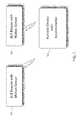
- FIG. 3is a block diagram illustrating components used in the portable device as seen in FIG. 1 .
- the portable device 300includes a radio transceiver 301 that connects to a microprocessor 303 for controlling operation of the transceiver 301 .
- a radio transceivermay operate in differing frequency ranges.
- An accelerometer 305also connects to the processor 303 for informing the processor when the portable device is moving at human-walking speed as described herein.
- a battery 307is connected to the BLE transceiver 301 , microprocessor 303 and the accelerometer 305 for powering these devices.
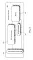
- FIG. 4is a block diagram illustrating components used in the beacon that uses motion sensing.
- the beacon 400includes components for transmitting radio transmissions and includes one or more transceivers 403 that connect to a microprocessor 405 for controlling the transceiver(s).
- a battery 409connects to the transceiver(s) 403 and the microprocessor 405 for powering these devices.
- the beacon 400typically is placed in the ceiling of a room so that portable devices can easily receive the beacon signal from the transceiver 403 when the portable devices s are moved between locations, e.g. between rooms.
- the beacon 400includes one or more antennas 401 for providing gain.
- the beaconincludes an in-room motion sensor 407 , such as a Passive-Infrared sensor, which detects human motion in the room where the beacon is located, by tracking changes in the infrared radiation in the room.
- the motion sensor 407is connected to both the microprocessor 405 and battery 409 , for detecting motion of any object within its room and/or proximity location. Thus, the motion sensor 407 can determine if there is human motion moving about it, to assist a portable device. This information will also be included in its radio transmission.
- the portable devicecan correlate the motion status of rooms, to motion patterns of its own accelerometer, and prefer location-estimation for rooms that are reported to have coincident motion. If the radio signals by themselves are not conclusive enough for the portable device to determine which room it is in, the motion information contained in the radio transmissions will assist in adding room-level precision.
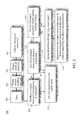
- FIG. 5is a block diagram illustrating the location-estimation process.
- the method(s) 500 as shown in FIG. 5include starting the process 501 where a portable device senses motion 503 .
- the portable devicewill determine which beacon signals it receives 505 and the portable device will perform an analysis where it will identify the strongest beacons 507 .
- the portable devicemay consider just a single, current signal strength report that it receives, or it may consider a longer-term pattern of signal-strength reports that it receives.
- the portable devicewill then consider whether it is entering the room with the strongest beacon by determining if the strength of the strongest beacon is increasing over time 509 . If not, the portable device will withhold from sending a location update 515 .
- the portable devicewill then consider whether the increasing-strength beacon has exceeded a sufficient threshold 511 . If not, the portable device will withhold from sending a location update 515 .
- the portable devicewill then consider whether that strongest beacon it is approaching is reporting that it sees human motion in its radio transmission 513 . If not, the portable device will withhold from sending a location update 515 . The portable device may then optionally consider other information in its logic, for example, determining from the information in various beacons' transmissions that the portable device has moved away from hallway beacons and toward an in-room beacon 517 . Based on the entire set of information available to it, including the motion status of the accelerometer, the motion status reported by surrounding beacons, the signal strength of surrounding beacons, the portable device estimates its room location with high accuracy 519 .
- radio signals sent by a beacon to the portable devicewill suffer from a variety of polarity fades (mismatches between the polarity of the transmitting antenna on the beacon and the receive antenna on the portable device), interference, blockages, absorption, and reflection.
- These effectswork to dispel the general assumption that the RSSI of the radio transmission from the beacon to the portable device is directly correlated to the distance between the beacon and the portable device. Therefore, this adds error to the location estimate, mis-estimating which room a portable device has entered. All of these radio-fading effects are time-varying, as people and metal objects move through the hospital's rooms, so using radio signal strength alone to estimate the location of a portable device will make a portable device mis-estimate its location from time to time.
- the beaconhas a motion sensor including but not limited to a passive infrared (IR) sensor, microwave sensor, area reflective sensor, ultrasonic and vibration sensors.
- IRpassive infrared
- microwave sensormicrowave sensor
- area reflective sensorarea reflective sensor
- ultrasonic and vibration sensorsEach motion sensor can detect motion of people inside its room, or detect lack of motion, and perhaps detect the difference between limited motion (like a patient sitting in a chair) and walking motion. Neither motion sensor can sense any motion on the opposite side of a wall.
- each beacon in each roomsends a regular radio transmission.
- the beaconsenses no motion in its room, it includes that “no-motion” status data in its transmission.
- the beaconsenses motion in its room, it includes that motion-sensor reading in its transmission.
- the motion-sense-status that the beacon reads in the roommay have more than two states: The states may be “no motion”, “the motion of a patient sitting in a bed or chair”, and “the motion of a human walking in a room”.
- the beacontherefore broadcasts (in its transmission) its motion-sense-status as more like a patient sitting in a bed, or more like a human walking through the room, for further accuracy of portable-device location fixes.
- each roomwill have a unique “motion fingerprint” for its last few minutes of observed time.
- a listening portable devicehears multiple beacons and wants to estimate which room it is in, it will evaluate the received signal strength of the beacon transmissions. Additionally, embodiments of the present invention, will estimate its room-location based on the coincident timing of its own changes in motion, and the timing of reported changes in motion from the neighboring beacons.
- the motion-sensing datais room-specific, enabling a room-level location fix, even for portable devices that are close to a neighboring room or suffering from interference.
- each portable devicecontains an accelerometer.
- the portable devicealways knows when it is moving, when it is not moving, and when it transitions from movement to stopped, with some sense of the pace of movement. So the portable device will estimate its room location, by favoring beacons (and therefore rooms) whose motion status matches the portable device's motion.
- each beaconmay include in its transmission another piece of data, viz. its room-type.
- the beacon's transmission of its room-typehelps the portable device to determine whether it is entering a room where room-level location is important (such as a patient room), vis-à-vis entering a hallway.
- typical “room types” in a hospital settingmay include but are not limited to patient room, hallway, equipment storage room, and elevator lobby.
- the portable devicemay optionally consider the room-type in its decision as to whether to report a room-level location.
- Each beaconmay include in its transmission another piece of data e.g. the floor on which it has been installed.
- a portable deviceknows that a movement from a patient room on one floor directly to a patient room on an adjacent floor is not likely (and a radio algorithm that reports such a change may be mistaken because of a spurious radio signal from another floor). Therefore, the portable device will be told to reject an apparent floor-hop from a patient room to another floor, because that move is unlikely. But a transition from a hallway on one floor to a patient room on the same floor is very possible, so the portable device should accept that reported location change when it is confirmed by the signal strength and motion-sensing algorithm.
- the portable device in the current inventionuses both beacon-sensed-and-reported human-motion information, and radio signal strength, to estimate the location of a portable device. The location estimate will be more accurate over the portable device using radio signal strength alone.
Landscapes
- Engineering & Computer Science (AREA)
- Computer Networks & Wireless Communication (AREA)
- Signal Processing (AREA)
- Physics & Mathematics (AREA)
- General Physics & Mathematics (AREA)
- Radar, Positioning & Navigation (AREA)
- Remote Sensing (AREA)
- Electromagnetism (AREA)
- Quality & Reliability (AREA)
- Business, Economics & Management (AREA)
- Emergency Management (AREA)
- Human Computer Interaction (AREA)
- Position Fixing By Use Of Radio Waves (AREA)
- Mobile Radio Communication Systems (AREA)
Abstract
Description
Claims (10)
Priority Applications (3)
| Application Number | Priority Date | Filing Date | Title |
|---|---|---|---|
| US16/214,979US10412700B2 (en) | 2016-05-31 | 2018-12-10 | Portable-device-locating system that uses room-level motion sensors and RSSI measurements to determine precise room-location |
| EP19822878.5AEP3807853A1 (en) | 2018-06-18 | 2019-06-18 | A real-time location system (rtls) that uses a combination of event sensors and rssi measurements to determine room-and-bay-location of tags |
| PCT/US2019/037667WO2019246049A1 (en) | 2018-06-18 | 2019-06-18 | A real-time location system (rtls) that uses a combination of event sensors and rssi measurements to determine room-and-bay-location of tags |
Applications Claiming Priority (4)
| Application Number | Priority Date | Filing Date | Title |
|---|---|---|---|
| US201662343242P | 2016-05-31 | 2016-05-31 | |
| US15/610,072US10028105B1 (en) | 2016-05-31 | 2017-05-31 | Bluetooth low energy (BLE) real-time location system (RTLS) having tags that harvest energy, bridges that instruct tags to toggle beacon modes on and off, beacons and bridges that self-report location changes, and optional use of a single beacon channel |
| US16/010,747US10251020B1 (en) | 2016-05-31 | 2018-06-18 | Bluetooth low energy (BLE) real-time location system (RTLS) having tags, beacons and bridges, that use a combination of motion detection and RSSI measurements to determine room-location of the tags |
| US16/214,979US10412700B2 (en) | 2016-05-31 | 2018-12-10 | Portable-device-locating system that uses room-level motion sensors and RSSI measurements to determine precise room-location |
Related Parent Applications (1)
| Application Number | Title | Priority Date | Filing Date |
|---|---|---|---|
| US16/010,747Continuation-In-PartUS10251020B1 (en) | 2016-05-31 | 2018-06-18 | Bluetooth low energy (BLE) real-time location system (RTLS) having tags, beacons and bridges, that use a combination of motion detection and RSSI measurements to determine room-location of the tags |
Publications (2)
| Publication Number | Publication Date |
|---|---|
| US20190141663A1 US20190141663A1 (en) | 2019-05-09 |
| US10412700B2true US10412700B2 (en) | 2019-09-10 |
Family
ID=66327970
Family Applications (1)
| Application Number | Title | Priority Date | Filing Date |
|---|---|---|---|
| US16/214,979ActiveUS10412700B2 (en) | 2016-05-31 | 2018-12-10 | Portable-device-locating system that uses room-level motion sensors and RSSI measurements to determine precise room-location |
Country Status (1)
| Country | Link |
|---|---|
| US (1) | US10412700B2 (en) |
Families Citing this family (5)
| Publication number | Priority date | Publication date | Assignee | Title |
|---|---|---|---|---|
| CN107000975B (en)* | 2014-12-02 | 2019-10-18 | 奥的斯电梯公司 | Method and system for the indoor pathfinding based on elevator information |
| US11039276B2 (en)* | 2018-12-14 | 2021-06-15 | Denso International America, Inc. | System and method of calibration for establishing real-time location |
| WO2020244946A1 (en)* | 2019-06-03 | 2020-12-10 | Koninklijke Philips N.V. | Systems and methods for hospital asset logistics optimization |
| CN114245990B (en) | 2019-08-13 | 2024-05-28 | 米沃奇电动工具公司 | Tool Tracking System |
| US11134368B1 (en)* | 2020-05-29 | 2021-09-28 | T-Mobile Usa, Inc. | Conveying precise civic address with an emergency call |
Citations (29)
| Publication number | Priority date | Publication date | Assignee | Title |
|---|---|---|---|---|
| US20030197612A1 (en) | 2002-03-26 | 2003-10-23 | Kabushiki Kaisha Toshiba | Method of and computer program product for monitoring person's movements |
| US20070046434A1 (en) | 2005-08-31 | 2007-03-01 | Skyetek, Inc. | Decoupled RFID reader and interrogator |
| US20070247366A1 (en)* | 2003-10-22 | 2007-10-25 | Smith Derek M | Wireless postion location and tracking system |
| US20080172271A1 (en) | 2007-01-16 | 2008-07-17 | Nhn Corporation | Method and apparatus for monitoring invalid clicks |
| US20100280874A1 (en) | 2009-04-29 | 2010-11-04 | Sony Ericsson Mobile Communications Ab | Mobile device, network server and method for evaluating correlation between advertisement information and user behavior |
| US20100328073A1 (en) | 2009-06-30 | 2010-12-30 | Intermec Ip Corp. | Method and system to determine the position, orientation, size, and movement of rfid tagged objects |
| US20110072132A1 (en) | 2009-09-21 | 2011-03-24 | Checkpoint Systems, Inc. | Retail Product Tracking System, Method, and Apparatus |
| US20110080267A1 (en) | 2009-10-02 | 2011-04-07 | Checkpoint Systems, Inc. | Calibration of Beamforming Nodes in a Configurable Monitoring Device System |
| US20130141233A1 (en) | 2011-02-23 | 2013-06-06 | Embedrf Llc | Position tracking and mobility assessment system |
| US20130201003A1 (en) | 2010-04-26 | 2013-08-08 | Sithamparanathan Sabesan | Rfid tag location systems |
| US20130231775A1 (en) | 2011-08-23 | 2013-09-05 | Vendrx, Inc. | Systems and methods for dispensing beneficial products |
| US20140197926A1 (en) | 2008-02-14 | 2014-07-17 | Intermec Ip Corp. | Utilization of motion and spatial identification in rfid systems |
| US20140351498A1 (en) | 2009-05-12 | 2014-11-27 | HGST Netherlands B.V. | Systems and methods for read caching in flash storage |
| US20150063472A1 (en) | 2013-08-28 | 2015-03-05 | Geoffrey W. Chatterton | Wireless technology bridging system |
| US20150269818A1 (en) | 2014-03-18 | 2015-09-24 | Symbol Technologies, Inc. | Modifying rfid system operation using movement detection |
| US20150286852A1 (en)* | 2014-04-06 | 2015-10-08 | Trackblue, Llc | Wireless Medication Compliance Sensing Device, System, and Related Methods |
| US20150371068A1 (en) | 2014-06-23 | 2015-12-24 | Sony Corporation | Tag Powersave |
| US20160029176A1 (en)* | 2014-07-23 | 2016-01-28 | Apple Inc. | Providing personalized content based on historical interaction with a mobile device |
| US20160029160A1 (en)* | 2014-07-25 | 2016-01-28 | Charles Theurer | Wireless bridge hardware system for active rfid identification and location tracking |
| US20160267144A1 (en)* | 2015-03-12 | 2016-09-15 | WeLink, Inc. | Collecting and generating geo-tagged social media data through a network router interface |
| US20160295358A1 (en) | 2013-09-27 | 2016-10-06 | Blue Sync Limited | Communication method and system |
| US20160295376A1 (en) | 2015-04-06 | 2016-10-06 | Awarepoint Corporation | Bluetooth low energy location system and method |
| US20160299213A1 (en)* | 2015-04-10 | 2016-10-13 | Enovate Medical, Llc | Asset tags |
| US20170127128A1 (en)* | 2015-11-02 | 2017-05-04 | Stephen Vollentine Seger | Social Post Roll Up and Management System and Method of Use |
| US20170142549A1 (en) | 2015-11-12 | 2017-05-18 | Trackr, Inc. | System and method for tracking items within a defined area |
| US20170195834A1 (en)* | 2016-01-05 | 2017-07-06 | Samsung Electronics Co., Ltd. | Method and apparatus for estimating location in a terminal |
| US20170313426A1 (en) | 2014-11-14 | 2017-11-02 | Bombardier Inc. | In-vehicle position detection and configuration of vehicle components |
| US9810767B1 (en) | 2015-06-16 | 2017-11-07 | Michael Hamilton | Location estimation system |
| US20180273344A1 (en)* | 2015-09-23 | 2018-09-27 | Inventio Ag | Wire bridge monitoring system |
- 2018
- 2018-12-10USUS16/214,979patent/US10412700B2/enactiveActive
Patent Citations (29)
| Publication number | Priority date | Publication date | Assignee | Title |
|---|---|---|---|---|
| US20030197612A1 (en) | 2002-03-26 | 2003-10-23 | Kabushiki Kaisha Toshiba | Method of and computer program product for monitoring person's movements |
| US20070247366A1 (en)* | 2003-10-22 | 2007-10-25 | Smith Derek M | Wireless postion location and tracking system |
| US20070046434A1 (en) | 2005-08-31 | 2007-03-01 | Skyetek, Inc. | Decoupled RFID reader and interrogator |
| US20080172271A1 (en) | 2007-01-16 | 2008-07-17 | Nhn Corporation | Method and apparatus for monitoring invalid clicks |
| US20140197926A1 (en) | 2008-02-14 | 2014-07-17 | Intermec Ip Corp. | Utilization of motion and spatial identification in rfid systems |
| US20100280874A1 (en) | 2009-04-29 | 2010-11-04 | Sony Ericsson Mobile Communications Ab | Mobile device, network server and method for evaluating correlation between advertisement information and user behavior |
| US20140351498A1 (en) | 2009-05-12 | 2014-11-27 | HGST Netherlands B.V. | Systems and methods for read caching in flash storage |
| US20100328073A1 (en) | 2009-06-30 | 2010-12-30 | Intermec Ip Corp. | Method and system to determine the position, orientation, size, and movement of rfid tagged objects |
| US20110072132A1 (en) | 2009-09-21 | 2011-03-24 | Checkpoint Systems, Inc. | Retail Product Tracking System, Method, and Apparatus |
| US20110080267A1 (en) | 2009-10-02 | 2011-04-07 | Checkpoint Systems, Inc. | Calibration of Beamforming Nodes in a Configurable Monitoring Device System |
| US20130201003A1 (en) | 2010-04-26 | 2013-08-08 | Sithamparanathan Sabesan | Rfid tag location systems |
| US20130141233A1 (en) | 2011-02-23 | 2013-06-06 | Embedrf Llc | Position tracking and mobility assessment system |
| US20130231775A1 (en) | 2011-08-23 | 2013-09-05 | Vendrx, Inc. | Systems and methods for dispensing beneficial products |
| US20150063472A1 (en) | 2013-08-28 | 2015-03-05 | Geoffrey W. Chatterton | Wireless technology bridging system |
| US20160295358A1 (en) | 2013-09-27 | 2016-10-06 | Blue Sync Limited | Communication method and system |
| US20150269818A1 (en) | 2014-03-18 | 2015-09-24 | Symbol Technologies, Inc. | Modifying rfid system operation using movement detection |
| US20150286852A1 (en)* | 2014-04-06 | 2015-10-08 | Trackblue, Llc | Wireless Medication Compliance Sensing Device, System, and Related Methods |
| US20150371068A1 (en) | 2014-06-23 | 2015-12-24 | Sony Corporation | Tag Powersave |
| US20160029176A1 (en)* | 2014-07-23 | 2016-01-28 | Apple Inc. | Providing personalized content based on historical interaction with a mobile device |
| US20160029160A1 (en)* | 2014-07-25 | 2016-01-28 | Charles Theurer | Wireless bridge hardware system for active rfid identification and location tracking |
| US20170313426A1 (en) | 2014-11-14 | 2017-11-02 | Bombardier Inc. | In-vehicle position detection and configuration of vehicle components |
| US20160267144A1 (en)* | 2015-03-12 | 2016-09-15 | WeLink, Inc. | Collecting and generating geo-tagged social media data through a network router interface |
| US20160295376A1 (en) | 2015-04-06 | 2016-10-06 | Awarepoint Corporation | Bluetooth low energy location system and method |
| US20160299213A1 (en)* | 2015-04-10 | 2016-10-13 | Enovate Medical, Llc | Asset tags |
| US9810767B1 (en) | 2015-06-16 | 2017-11-07 | Michael Hamilton | Location estimation system |
| US20180273344A1 (en)* | 2015-09-23 | 2018-09-27 | Inventio Ag | Wire bridge monitoring system |
| US20170127128A1 (en)* | 2015-11-02 | 2017-05-04 | Stephen Vollentine Seger | Social Post Roll Up and Management System and Method of Use |
| US20170142549A1 (en) | 2015-11-12 | 2017-05-18 | Trackr, Inc. | System and method for tracking items within a defined area |
| US20170195834A1 (en)* | 2016-01-05 | 2017-07-06 | Samsung Electronics Co., Ltd. | Method and apparatus for estimating location in a terminal |
Also Published As
| Publication number | Publication date |
|---|---|
| US20190141663A1 (en) | 2019-05-09 |
Similar Documents
| Publication | Publication Date | Title |
|---|---|---|
| US10412700B2 (en) | Portable-device-locating system that uses room-level motion sensors and RSSI measurements to determine precise room-location | |
| US10390182B2 (en) | Real-time location system (RTLS) having tags, beacons and bridges, that uses a combination of motion detection and RSSI measurements to determine room-location of the tags | |
| US10231078B1 (en) | Bluetooth low energy (BLE) real-time location system (RTLS) having simple transmitting tags, beacons and bridges, that use a combination of motion detection and RSSI measurements to determine room-location of the tags | |
| AU2023202901B2 (en) | Transmitting device for use in location determination systems | |
| KR100859093B1 (en) | Navigation device and method using RFCID | |
| US10257659B2 (en) | Positioning device and positioning system | |
| US9625567B2 (en) | Positioning system using sound waves | |
| US10591972B2 (en) | Adaptively controlling a tradeoff between computational accuracy and power consumption of a mobile device that operates to select a condition of a subject or device | |
| KR101600190B1 (en) | Indoor positioning apparatus considering environmental parameters and method thereof | |
| Zhu et al. | Survey of indoor positioning technologies and systems | |
| US10251020B1 (en) | Bluetooth low energy (BLE) real-time location system (RTLS) having tags, beacons and bridges, that use a combination of motion detection and RSSI measurements to determine room-location of the tags | |
| JP2010515044A (en) | Object or person position detection system | |
| JP3587448B2 (en) | Position detection system and position detection method | |
| JP6160036B2 (en) | Mobile communication device and position information notification method | |
| WO2013169612A1 (en) | Low frequency magnetic induction positioning system and method | |
| JP2017032428A (en) | Mobile terminal, route guidance method and program | |
| JP2022546532A (en) | positioning | |
| JP2007114003A (en) | System for detecting contactless ic tag position | |
| Lee et al. | Low-cost indoor human tracking by utilizing fluctuation of received radio signal strength | |
| US7382317B1 (en) | Two-stage location system | |
| EP3982145A1 (en) | Indoor location system | |
| JP2011203129A (en) | Position estimation system and method | |
| KR20160146382A (en) | A specifying method and system for settling position | |
| Lovis | Challenges and issues of geolocation in clinical environment | |
| Memon et al. | Real-time indoor positioning and route guidance system by using beacons |
Legal Events
| Date | Code | Title | Description |
|---|---|---|---|
| FEPP | Fee payment procedure | Free format text:ENTITY STATUS SET TO UNDISCOUNTED (ORIGINAL EVENT CODE: BIG.); ENTITY STATUS OF PATENT OWNER: LARGE ENTITY Free format text:ENTITY STATUS SET TO UNDISCOUNTED (ORIGINAL EVENT CODE: BIG.); ENTITY STATUS OF PATENT OWNER: SMALL ENTITY | |
| FEPP | Fee payment procedure | Free format text:ENTITY STATUS SET TO SMALL (ORIGINAL EVENT CODE: SMAL); ENTITY STATUS OF PATENT OWNER: LARGE ENTITY Free format text:ENTITY STATUS SET TO SMALL (ORIGINAL EVENT CODE: SMAL); ENTITY STATUS OF PATENT OWNER: SMALL ENTITY | |
| AS | Assignment | Owner name:INFINITE LEAP, INC., NORTH DAKOTA Free format text:ASSIGNMENT OF ASSIGNORS INTEREST;ASSIGNOR:SWART, JOHN A.;REEL/FRAME:047966/0575 Effective date:20181129 | |
| AS | Assignment | Owner name:INFINITE LEAP HOLDINGS, LLC, NORTH DAKOTA Free format text:ASSIGNMENT OF ASSIGNORS INTEREST;ASSIGNOR:INFINITE LEAP, INC.;REEL/FRAME:048595/0031 Effective date:20190312 | |
| STPP | Information on status: patent application and granting procedure in general | Free format text:RESPONSE TO NON-FINAL OFFICE ACTION ENTERED AND FORWARDED TO EXAMINER | |
| STPP | Information on status: patent application and granting procedure in general | Free format text:PUBLICATIONS -- ISSUE FEE PAYMENT RECEIVED | |
| STPP | Information on status: patent application and granting procedure in general | Free format text:PUBLICATIONS -- ISSUE FEE PAYMENT VERIFIED | |
| STCF | Information on status: patent grant | Free format text:PATENTED CASE | |
| AS | Assignment | Owner name:INFINITE LEAP HOLDINGS, LLC, NORTH DAKOTA Free format text:CORRECTIVE ASSIGNMENT TO CORRECT THE CONVEYING PARTY OF STATE INCORPORATION ON DOCUMENT PREVIOUSLY RECORDED AT REEL: 48595 FRAME: 031. ASSIGNOR(S) HEREBY CONFIRMS THE ASSIGNMENT;ASSIGNOR:INFINITE LEAP, INC.;REEL/FRAME:057639/0846 Effective date:20190312 | |
| AS | Assignment | Owner name:INFINITE LEAP, INC., NORTH DAKOTA Free format text:ASSIGNMENT OF ASSIGNORS INTEREST;ASSIGNOR:INFINITE LEAP HOLDINGS, LLC;REEL/FRAME:057457/0421 Effective date:20210910 | |
| FEPP | Fee payment procedure | Free format text:ENTITY STATUS SET TO UNDISCOUNTED (ORIGINAL EVENT CODE: BIG.); ENTITY STATUS OF PATENT OWNER: LARGE ENTITY | |
| MAFP | Maintenance fee payment | Free format text:PAYMENT OF MAINTENANCE FEE, 4TH YEAR, LARGE ENTITY (ORIGINAL EVENT CODE: M1551); ENTITY STATUS OF PATENT OWNER: LARGE ENTITY Year of fee payment:4 |