US10409239B2 - Wireless sensor device with wireless remote programming - Google Patents
Wireless sensor device with wireless remote programmingDownload PDFInfo
- Publication number
- US10409239B2 US10409239B2US15/449,480US201715449480AUS10409239B2US 10409239 B2US10409239 B2US 10409239B2US 201715449480 AUS201715449480 AUS 201715449480AUS 10409239 B2US10409239 B2US 10409239B2
- Authority
- US
- United States
- Prior art keywords
- sensor device
- wireless sensor
- battery
- controller
- sleep
- Prior art date
- Legal status (The legal status is an assumption and is not a legal conclusion. Google has not performed a legal analysis and makes no representation as to the accuracy of the status listed.)
- Active, expires
Links
Images

Classifications
- G—PHYSICS
- G05—CONTROLLING; REGULATING
- G05B—CONTROL OR REGULATING SYSTEMS IN GENERAL; FUNCTIONAL ELEMENTS OF SUCH SYSTEMS; MONITORING OR TESTING ARRANGEMENTS FOR SUCH SYSTEMS OR ELEMENTS
- G05B15/00—Systems controlled by a computer
- G05B15/02—Systems controlled by a computer electric
- F—MECHANICAL ENGINEERING; LIGHTING; HEATING; WEAPONS; BLASTING
- F24—HEATING; RANGES; VENTILATING
- F24F—AIR-CONDITIONING; AIR-HUMIDIFICATION; VENTILATION; USE OF AIR CURRENTS FOR SCREENING
- F24F11/00—Control or safety arrangements
- F24F11/30—Control or safety arrangements for purposes related to the operation of the system, e.g. for safety or monitoring
- F—MECHANICAL ENGINEERING; LIGHTING; HEATING; WEAPONS; BLASTING
- F24—HEATING; RANGES; VENTILATING
- F24F—AIR-CONDITIONING; AIR-HUMIDIFICATION; VENTILATION; USE OF AIR CURRENTS FOR SCREENING
- F24F11/00—Control or safety arrangements
- F24F11/50—Control or safety arrangements characterised by user interfaces or communication
- F24F11/56—Remote control
- F—MECHANICAL ENGINEERING; LIGHTING; HEATING; WEAPONS; BLASTING
- F24—HEATING; RANGES; VENTILATING
- F24F—AIR-CONDITIONING; AIR-HUMIDIFICATION; VENTILATION; USE OF AIR CURRENTS FOR SCREENING
- F24F11/00—Control or safety arrangements
- F24F11/62—Control or safety arrangements characterised by the type of control or by internal processing, e.g. using fuzzy logic, adaptive control or estimation of values
- F24F11/63—Electronic processing
- F24F11/65—Electronic processing for selecting an operating mode
- F24F11/66—Sleep mode
- H—ELECTRICITY
- H04—ELECTRIC COMMUNICATION TECHNIQUE
- H04L—TRANSMISSION OF DIGITAL INFORMATION, e.g. TELEGRAPHIC COMMUNICATION
- H04L12/00—Data switching networks
- H04L12/28—Data switching networks characterised by path configuration, e.g. LAN [Local Area Networks] or WAN [Wide Area Networks]
- H04L12/2803—Home automation networks
- H04L12/2816—Controlling appliance services of a home automation network by calling their functionalities
- F—MECHANICAL ENGINEERING; LIGHTING; HEATING; WEAPONS; BLASTING
- F24—HEATING; RANGES; VENTILATING
- F24F—AIR-CONDITIONING; AIR-HUMIDIFICATION; VENTILATION; USE OF AIR CURRENTS FOR SCREENING
- F24F11/00—Control or safety arrangements
- F24F11/30—Control or safety arrangements for purposes related to the operation of the system, e.g. for safety or monitoring
- F24F11/46—Improving electric energy efficiency or saving
- F—MECHANICAL ENGINEERING; LIGHTING; HEATING; WEAPONS; BLASTING
- F24—HEATING; RANGES; VENTILATING
- F24F—AIR-CONDITIONING; AIR-HUMIDIFICATION; VENTILATION; USE OF AIR CURRENTS FOR SCREENING
- F24F11/00—Control or safety arrangements
- F24F11/62—Control or safety arrangements characterised by the type of control or by internal processing, e.g. using fuzzy logic, adaptive control or estimation of values
- F24F11/63—Electronic processing
- F24F11/65—Electronic processing for selecting an operating mode
- F—MECHANICAL ENGINEERING; LIGHTING; HEATING; WEAPONS; BLASTING
- F24—HEATING; RANGES; VENTILATING
- F24F—AIR-CONDITIONING; AIR-HUMIDIFICATION; VENTILATION; USE OF AIR CURRENTS FOR SCREENING
- F24F2120/00—Control inputs relating to users or occupants
- F24F2120/10—Occupancy
- F—MECHANICAL ENGINEERING; LIGHTING; HEATING; WEAPONS; BLASTING
- F24—HEATING; RANGES; VENTILATING
- F24F—AIR-CONDITIONING; AIR-HUMIDIFICATION; VENTILATION; USE OF AIR CURRENTS FOR SCREENING
- F24F2120/00—Control inputs relating to users or occupants
- F24F2120/10—Occupancy
- F24F2120/12—Position of occupants
- F—MECHANICAL ENGINEERING; LIGHTING; HEATING; WEAPONS; BLASTING
- F24—HEATING; RANGES; VENTILATING
- F24F—AIR-CONDITIONING; AIR-HUMIDIFICATION; VENTILATION; USE OF AIR CURRENTS FOR SCREENING
- F24F2140/00—Control inputs relating to system states
- F24F2140/60—Energy consumption
- H—ELECTRICITY
- H04—ELECTRIC COMMUNICATION TECHNIQUE
- H04L—TRANSMISSION OF DIGITAL INFORMATION, e.g. TELEGRAPHIC COMMUNICATION
- H04L12/00—Data switching networks
- H04L12/28—Data switching networks characterised by path configuration, e.g. LAN [Local Area Networks] or WAN [Wide Area Networks]
- H04L12/2803—Home automation networks
- H04L2012/284—Home automation networks characterised by the type of medium used
- H04L2012/2841—Wireless
Definitions
- the disclosurerelates generally to wireless sensor devices, and more particularly, to remote programming of wireless sensor devices.
- Wireless sensor devicesare often used in control applications such as building control applications. Such wireless sensor devices often include a sensor for sensing a condition in the building.
- the wireless sensor devicemay wirelessly transmit the sensed condition to a remotely located controller, such as a remotely located building controller.
- a remotely located building controllermay use the sensed condition to control a building system, such as an HVAC system, a security system, a fire detection system, or any other system.
- the disclosurerelates generally to wireless sensor devices, and more particularly, to remote programming of wireless sensor devices.
- a building controllermay wirelessly send one or more messages to a wireless sensor device in order to change the behavior of the wireless sensor device, even while the wireless sensor device and building controller are on-line and actively controlling a building control system.
- a technician or installermay use a diagnostic or setup tool to send one or more messages to a wireless sensor device to change the behavior of the wireless sensor device.
- a building controllermay be programmed to wirelessly send one or more messages to a wireless sensor device in order to change a sleep algorithm used by the wireless sensor device.
- a battery-powered wireless sensor deviceincludes a battery for providing power to the wireless sensor device, a sensor for sensing one or more conditions in or around the wireless sensor device, a wireless transceiver for wirelessly sending and receiving messages to/from a remotely located device such as a remotely located building control device, a memory for storing one or more parameter values and a controller in communication with the battery, the sensor, the wireless transceiver and the memory.
- the controllermay be configured to: switch the wireless sensor device between a lower power sleep mode and a higher power awake mode, wherein in the lower power sleep mode, the wireless sensor device does not send or receive messages to/from the remotely located device via the wireless transceiver; receive one or more messages from the remotely located device via the transceiver of the wireless sensor device, wherein the one or more messages specify a sleep algorithm to be used by the controller to determine when to switch the wireless sensor device between the lower power sleep mode and the higher power awake mode; and subsequently switch between the lower power sleep mode and the higher power awake mode in accordance with the sleep algorithm specified by the one or more messages from the remotely located device.
- the controller of the wireless sensor devicemay be configured to: receive one or more parameter setting messages from the remotely located device via the transceiver in the higher power awake mode, wherein the one or more parameter setting messages provide one or more parameter values, the one or more parameter values stored into the memory; and determine when to switch between the lower power sleep mode and the higher power awake mode based on one or more sleep algorithms, wherein at least one of the one or more sleep algorithms is dependent upon one or more of the parameter values received from the remotely located device and stored in the memory.
- the controller of the wireless sensor devicemay be configured to: receive one or more messages from a remotely located device via the transceiver, wherein the one or more messages specify one or more rules for operating the wireless sensor device; and operate the wireless sensor device in accordance with the one or more rules.
- the one or more rulesmay define, at least in part, a sleep algorithm that is used to determine when to switch the wireless sensor device between the lower power sleep mode and the higher power awake mode.
- the one or more rulesmay define how long to wait for an acknowledgement during communication with the remotely located device, how often to transmit the sensed condition, sometimes depending on the condition of the battery.
- wireless sensor devicesare used as one example, it is contemplated that the principles disclosed herein may be applied to wireless building controllers such as wireless thermostats, wireless zone controllers, wireless equipment interface modules, wireless security system controllers, wireless building control actuators such as wireless damper and valve actuators, and any other suitable wireless building control device, as desired.
- wireless building controllerssuch as wireless thermostats, wireless zone controllers, wireless equipment interface modules, wireless security system controllers, wireless building control actuators such as wireless damper and valve actuators, and any other suitable wireless building control device, as desired.
- FIG. 1is a schematic view of an illustrative but non-limiting wireless sensor device having a controller in wireless communication with a remotely located device.
- a battery powered wireless sensor deviceis used as an example below, it is contemplated that the present disclosure can be applied to any suitable device, as desired.
- the disclosuremay be applied to devices that are powered by a wall current or are plugged into other devices for power, rather than just battery powered.
- the disclosuremay be applied to devices that control other devices, such as general purpose input/output (GPIO), rather than just sensor devices.
- GPIOgeneral purpose input/output
- the disclosuremay be applied to wireless building controllers such as wireless thermostats, wireless zone controllers, wireless equipment interface modules, wireless security system controllers, wireless building control actuators such as wireless damper and valve actuators, and/or any other suitable wireless building control device, as desired.
- wireless building controllerssuch as wireless thermostats, wireless zone controllers, wireless equipment interface modules, wireless security system controllers, wireless building control actuators such as wireless damper and valve actuators, and/or any other suitable wireless building control device, as desired.
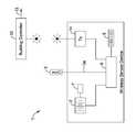
- FIG. 1is a schematic view of an illustrative but non-limiting wireless sensor device 1 in wireless communication with a remotely located device 10 .
- the wireless sensor device 1may operate on battery power and, as such, may implement various algorithms to help conserve battery power when possible.
- the wireless sensor device 1may include a sensor 3 , such as a temperature sensor, a humidity sensor, a pressure sensor, a flow sensor, a motion sensor, an acoustical sensor, a magnetic sensor, a contact sensor, a light sensor, and/or any other suitable sensor.
- the wireless sensor device 1may sense an ambient condition (e.g. temperature, humidity, etc.) in or around the wireless sensor device 1 .
- the wireless sensor device 1may include a wireless transceiver 14 for wirelessly sending and receiving messages to/from a remotely located device 10 , such as a remotely located building controller.
- a remotely located device 10such as a remotely located building controller.
- the remotely located device 10may be a diagnostic or setup tool that may be used by a technician or installer to send one or more messages to the wireless sensor device 1 .
- the remotely located device 10may be a building controller.
- the wireless sensor device 1may send messages to the building controller that includes a measure related to the condition sensed by the sensor 3 of the wireless sensor device 1 .
- the building controllermay use the measure related to the sensed condition to determine and then send one or more control signals 12 to a building control system (not shown).
- the building control systemmay be, for example, an HVAC system, a security system, a fire detection system, and/or any other suitable building control system as desired.
- the wireless sensor device 1may include a battery 2 , which may be rechargeable or replaceable. In general, it is desirable to lengthen the time between recharging or replacement of the battery 2 .
- the wireless sensor device 1also includes a sensor 3 that senses one or more conditions in or around the wireless sensor device 1 , a wireless transceiver 14 for wirelessly sending and receiving messages to and/or from the remotely located device 10 , and a memory 5 for storing one or more parameter values.
- the illustrative wireless sensor device 1 of FIG. 1also includes a controller 6 .
- the controller 6communicates with the battery 2 , the sensor 3 , the wireless transceiver 14 and the memory 5 .
- the controller 6may received power from, and in some cases, monitor the current flowing from the battery 2 and/or the voltage provided by the battery 2 .
- the controller 6may determine an amount of life left in the battery 2 .
- the controller 6may be programmed to operate differently depending on the amount of life left in the battery 2 . For example, the controller may increase the time between when the sensed condition is transmitted to the remotely located device 10 after the amount of life left in the battery 2 falls below a threshold value.
- the controller 6may poll the sensor 3 at a particular time and may receive a reading from the sensor 3 in response.
- the controller 6may receive and interpret messages that arrive through the wireless transceiver 14 , and may compose and transmit messages through the wireless transceiver 14 .
- the controller 6may store and retrieve particular parameter values, algorithms, and other data as needed.
- the controller 6may be configured to switch the wireless sensor device 1 between a lower power sleep mode and a higher power awake mode. In the lower power sleep mode, the wireless sensor device 1 may not send or receive messages to/from the remotely located device 10 via the wireless transceiver 14 . In the higher power awake mode, the controller 6 may be configured to send and/or receive one or more messages to/from the remotely located device 10 via the wireless transceiver 14 .
- the “lower power sleep mode” and the “higher power awake mode” discussed hereinmay be thought of as being a “quiet” mode and a “talking” mode, respectively, where being “quiet” can have the potential advantages of saving power, preserving wireless and/or wired channel capacity, and/or preventing unneeded processing of data.
- the one or more messages from the remotely located device 10may specify a sleep algorithm that is to be used by the controller 6 to determine when to switch the wireless sensor device 1 between the lower power sleep mode and the higher power awake mode during subsequent operation of the wireless sensor device 1 .
- the controller 6may be configured to subsequently switch between the lower power sleep mode and the higher power awake mode in accordance with the sleep algorithm specified by the one or more messages from the remotely located device 10 .
- the sensor 3may provide a sensor signal 3 a that encodes a measure related to the sensed condition in or around the wireless sensor device 1 .
- the sleep algorithmmay use, at least in part, the sensor signal 3 a to determine when to switch the wireless sensor device 1 between the lower power sleep mode and the higher power awake mode.
- the sleep algorithmmay use a measure related to a rate of change of the sensor signal 3 a to determine when to switch the wireless sensor device 1 between the lower power sleep mode and the higher power awake mode.
- the one or more messagesmay identify a desired sleep algorithm. It is contemplated that the sleep mode may be communicated and switched even while the wireless sensor device 1 and building controller 10 are on-line and actively controlling a building control system.
- the wireless sensor device 1may include a battery condition monitor 7 that provides a measure related to the current charge condition of the battery 2 .
- the sleep algorithmmay use, at least in part, a measure related to the current charge condition of the battery 2 to determine when to switch the wireless sensor device between the lower power sleep mode and the higher power awake mode.
- the sleep algorithmmay increase the time the wireless sensor device 1 is in the lower power sleep mode relative to the higher power awake mode as the condition of the battery 2 deteriorates over time and/or crosses a threshold value.
- the controller 6may establish communication with the remotely located device 10 via a wireless link and/or wireless network.
- the sleep algorithmmay keep the wireless sensor device 1 in the higher power awake mode until the controller 6 establishes communication with the remotely located device 10 via the wireless link or wireless network.
- the controller 6may be configured to receive one or more parameter setting messages from the remotely located device 10 via the wireless transceiver 14 in the higher power awake mode.
- the one or more parameter setting messagesmay provide one or more parameter values, which may be stored in memory 5 .
- the controller 6may determine when to switch between the lower power sleep mode and the higher power awake mode based on one or more sleep algorithms that read up or otherwise are dependent upon one or more of the parameter values. For example, and in some instances, at least one of the one or more sleep algorithms uses a sleep interval that corresponds to a sleep time between each of two or more successive higher power awake modes. In some cases, at least one of the parameter values of the parameter setting messages may correspond to the sleep interval.
- At least one of the one or more sleep algorithmsmay use a sleep interval for a set number of sleep periods.
- the parameter values of the parameter setting messagesmay set one or both of the sleep interval (e.g. 10 seconds) or the number of sleep periods (28800 sleep periods, which would set the sleep interval to be 10 seconds for the next 8 hours).
- New parameter valuesmay be sent via one or more subsequent parameter setting messages to set a different sleep interval and/or a different period of time, as desired.
- the remotely located device 10may be a building controller (e.g. HVAC Controller) that stores and executes a programmable schedule such as a programmable temperature schedule.
- the temperature schedulemay include a more energy efficient set point during a scheduled unoccupied time period and a less energy efficient set point during a scheduled occupied time period.
- the HVAC controllermay send one or more first parameter setting messages to the wireless sensor device 1 that specify a first sleep interval in response to entering an unoccupied time period of the schedule, and may send one or more second parameter setting messages that specify a second sleep interval in response to entering a subsequent occupied time period of the schedule, even while the wireless sensor device 1 and the HVAC controller are on-line and actively controlling a building control system (e.g. HVAC system).
- a building controllere.g. HVAC Controller
- the controller 6 of the wireless sensor device 1may include a rules based engine that controls the operation of at least part of the wireless sensor device 1 according to a number of rules.
- the wireless sensor device 1may receive one or more messages from the remotely located device 10 via the wireless transceiver 14 that specify one or more rules.
- the rulesmay be stored in the memory 5 .
- the rules based engine of the controller 6may read up the rules from the memory 5 and control the operation of at least part of the wireless sensor device 1 according to the received rules.
- the one or more rulesmay define, at least in part, a sleep algorithm that is used to determine when to switch the wireless sensor device 1 between the lower power sleep mode and the higher power awake mode.
- the transceiver 4communicates with the remotely located device via a wireless network that includes a communication protocol that requires an acknowledgement to acknowledge a communication across the wireless network.
- the one or more rulesmay define how long to wait for an acknowledgement.
- the controller 6is configured to transmit a measure related to the one or more sensed conditions via the wireless transceiver 14 .
- the one or more rulesmay define, at least in part, how often to transmit the measure.
- the wireless sensor device 1may include a battery condition monitor 7 that provides a measure related to the current charge condition of the battery 2 .
- the one or more rulesmay define, at least in part, how often to transmit the measure based on the current charge condition of the battery 2 . Use of a rules based engine may simplify the definition, transmission and subsequent programming of the wireless sensor device 1 .
- An illustrative method for operating a wireless sensor device 1may include wirelessly receiving one or more first messages from the remotely located device 10 via the wireless transceiver 14 , wherein the one or more first messages may specify a first sleep algorithm that is used by the controller 6 to determine when to switch the wireless sensor device 1 between the lower power sleep mode and the higher power awake mode. The method may then execute the first sleep algorithm specified by the one or more first messages from the remotely located device 10 until one or more subsequent second messages are received from the remotely located device 10 that specify a second sleep algorithm, whereupon, the second sleep algorithm specified by the one or more subsequent second messages may be executed in place of the first sleep algorithm.
- the wireless sensor device 1may wirelessly receive one or more third messages from the remotely located device 10 via the wireless transceiver 14 .
- the one or more third messagesmay specify a third sleep algorithm that is used by the controller 6 to determine when to switch the wireless sensor device between the lower power sleep mode and the higher power awake mode.
- the controllermay then execute the third sleep algorithm specified by the one or more third messages from the remotely located device 10 in place of the second sleep algorithm.
- the first sleep algorithmallows more sleep time than the second sleep algorithm.
Landscapes
- Engineering & Computer Science (AREA)
- General Engineering & Computer Science (AREA)
- Mechanical Engineering (AREA)
- Chemical & Material Sciences (AREA)
- Combustion & Propulsion (AREA)
- Signal Processing (AREA)
- Physics & Mathematics (AREA)
- Mathematical Physics (AREA)
- Fuzzy Systems (AREA)
- Automation & Control Theory (AREA)
- Computer Networks & Wireless Communication (AREA)
- Human Computer Interaction (AREA)
- General Physics & Mathematics (AREA)
- Selective Calling Equipment (AREA)
Abstract
Description
This is a continuation of co-pending U.S. patent application Ser. No. 13/556,971, filed Jul. 24, 2012, entitled “WIRELESS SENSOR DEVICE WITH WIRELESS REMOTE PROGRAMMING”, which is incorporated herein by reference.
The disclosure relates generally to wireless sensor devices, and more particularly, to remote programming of wireless sensor devices.
Wireless sensor devices are often used in control applications such as building control applications. Such wireless sensor devices often include a sensor for sensing a condition in the building. The wireless sensor device may wirelessly transmit the sensed condition to a remotely located controller, such as a remotely located building controller. When so provided, the remotely located building controller may use the sensed condition to control a building system, such as an HVAC system, a security system, a fire detection system, or any other system.
The disclosure relates generally to wireless sensor devices, and more particularly, to remote programming of wireless sensor devices. In some cases, it may be desirable to wirelessly program a wireless sensor device from a remote location. For example, in some instances, a building controller may wirelessly send one or more messages to a wireless sensor device in order to change the behavior of the wireless sensor device, even while the wireless sensor device and building controller are on-line and actively controlling a building control system. In some instances, a technician or installer may use a diagnostic or setup tool to send one or more messages to a wireless sensor device to change the behavior of the wireless sensor device. These are just some examples.
In one illustrative embodiment, a building controller may be programmed to wirelessly send one or more messages to a wireless sensor device in order to change a sleep algorithm used by the wireless sensor device. In one example, a battery-powered wireless sensor device includes a battery for providing power to the wireless sensor device, a sensor for sensing one or more conditions in or around the wireless sensor device, a wireless transceiver for wirelessly sending and receiving messages to/from a remotely located device such as a remotely located building control device, a memory for storing one or more parameter values and a controller in communication with the battery, the sensor, the wireless transceiver and the memory.
In some instances, the controller may be configured to: switch the wireless sensor device between a lower power sleep mode and a higher power awake mode, wherein in the lower power sleep mode, the wireless sensor device does not send or receive messages to/from the remotely located device via the wireless transceiver; receive one or more messages from the remotely located device via the transceiver of the wireless sensor device, wherein the one or more messages specify a sleep algorithm to be used by the controller to determine when to switch the wireless sensor device between the lower power sleep mode and the higher power awake mode; and subsequently switch between the lower power sleep mode and the higher power awake mode in accordance with the sleep algorithm specified by the one or more messages from the remotely located device.
Alternatively, or in addition, the controller of the wireless sensor device may be configured to: receive one or more parameter setting messages from the remotely located device via the transceiver in the higher power awake mode, wherein the one or more parameter setting messages provide one or more parameter values, the one or more parameter values stored into the memory; and determine when to switch between the lower power sleep mode and the higher power awake mode based on one or more sleep algorithms, wherein at least one of the one or more sleep algorithms is dependent upon one or more of the parameter values received from the remotely located device and stored in the memory.
Alternatively, or in addition, the controller of the wireless sensor device may be configured to: receive one or more messages from a remotely located device via the transceiver, wherein the one or more messages specify one or more rules for operating the wireless sensor device; and operate the wireless sensor device in accordance with the one or more rules. In some cases, the one or more rules may define, at least in part, a sleep algorithm that is used to determine when to switch the wireless sensor device between the lower power sleep mode and the higher power awake mode. Alternatively, or in addition, the one or more rules may define how long to wait for an acknowledgement during communication with the remotely located device, how often to transmit the sensed condition, sometimes depending on the condition of the battery. These are just some examples.
While wireless sensor devices are used as one example, it is contemplated that the principles disclosed herein may be applied to wireless building controllers such as wireless thermostats, wireless zone controllers, wireless equipment interface modules, wireless security system controllers, wireless building control actuators such as wireless damper and valve actuators, and any other suitable wireless building control device, as desired.
The preceding summary is provided to facilitate an understanding of some of the features of the present disclosure and is not intended to be a full description. A full appreciation of the disclosure can be gained by taking the entire specification, claims, drawings, and abstract as a whole.
The disclosure may be more completely understood in consideration of the following description of various embodiments in connection with the accompanying drawing, in which:
While the disclosure is amenable to various modifications and alternative forms, specifics thereof have been shown by way of example in the drawing and will be described in detail. It should be understood, however, that the intention is not to limit aspects of the disclosure to the particular embodiments described. On the contrary, the intention is to cover all modifications, equivalents, and alternatives falling within the spirit and scope of the disclosure.
The following description should be read with reference to the drawing. The description and drawing are meant to illustrative in nature. While a battery powered wireless sensor device is used as an example below, it is contemplated that the present disclosure can be applied to any suitable device, as desired. For instance, the disclosure may be applied to devices that are powered by a wall current or are plugged into other devices for power, rather than just battery powered. As another example, the disclosure may be applied to devices that control other devices, such as general purpose input/output (GPIO), rather than just sensor devices. In some cases, the disclosure may be applied to wireless building controllers such as wireless thermostats, wireless zone controllers, wireless equipment interface modules, wireless security system controllers, wireless building control actuators such as wireless damper and valve actuators, and/or any other suitable wireless building control device, as desired.
In one example, the remotely locateddevice 10 may be a building controller. The wireless sensor device1 may send messages to the building controller that includes a measure related to the condition sensed by the sensor3 of the wireless sensor device1. The building controller may use the measure related to the sensed condition to determine and then send one ormore control signals 12 to a building control system (not shown). In some instances, the building control system may be, for example, an HVAC system, a security system, a fire detection system, and/or any other suitable building control system as desired.
In the example shown inFIG. 1 , the wireless sensor device1 may include abattery 2, which may be rechargeable or replaceable. In general, it is desirable to lengthen the time between recharging or replacement of thebattery 2. The wireless sensor device1 also includes a sensor3 that senses one or more conditions in or around the wireless sensor device1, awireless transceiver 14 for wirelessly sending and receiving messages to and/or from the remotely locateddevice 10, and amemory 5 for storing one or more parameter values.
The illustrative wireless sensor device1 ofFIG. 1 also includes acontroller 6. Thecontroller 6 communicates with thebattery 2, the sensor3, thewireless transceiver 14 and thememory 5. With regard to thebattery 2, thecontroller 6 may received power from, and in some cases, monitor the current flowing from thebattery 2 and/or the voltage provided by thebattery 2. In some cases, thecontroller 6 may determine an amount of life left in thebattery 2. In some instances, thecontroller 6 may be programmed to operate differently depending on the amount of life left in thebattery 2. For example, the controller may increase the time between when the sensed condition is transmitted to the remotely locateddevice 10 after the amount of life left in thebattery 2 falls below a threshold value. With regard to the sensor3, thecontroller 6 may poll the sensor3 at a particular time and may receive a reading from the sensor3 in response. With regard to thewireless transceiver 14, thecontroller 6 may receive and interpret messages that arrive through thewireless transceiver 14, and may compose and transmit messages through thewireless transceiver 14. With regard to thememory 5, thecontroller 6 may store and retrieve particular parameter values, algorithms, and other data as needed.
In some cases, thecontroller 6 may be configured to switch the wireless sensor device1 between a lower power sleep mode and a higher power awake mode. In the lower power sleep mode, the wireless sensor device1 may not send or receive messages to/from the remotely locateddevice 10 via thewireless transceiver 14. In the higher power awake mode, thecontroller 6 may be configured to send and/or receive one or more messages to/from the remotely locateddevice 10 via thewireless transceiver 14. In some instances, the “lower power sleep mode” and the “higher power awake mode” discussed herein may be thought of as being a “quiet” mode and a “talking” mode, respectively, where being “quiet” can have the potential advantages of saving power, preserving wireless and/or wired channel capacity, and/or preventing unneeded processing of data.
In some instances, the one or more messages from the remotely locateddevice 10 may specify a sleep algorithm that is to be used by thecontroller 6 to determine when to switch the wireless sensor device1 between the lower power sleep mode and the higher power awake mode during subsequent operation of the wireless sensor device1. Thecontroller 6 may be configured to subsequently switch between the lower power sleep mode and the higher power awake mode in accordance with the sleep algorithm specified by the one or more messages from the remotely locateddevice 10.
In some cases, the sensor3 may provide asensor signal 3athat encodes a measure related to the sensed condition in or around the wireless sensor device1. In some cases, the sleep algorithm may use, at least in part, thesensor signal 3ato determine when to switch the wireless sensor device1 between the lower power sleep mode and the higher power awake mode. Alternatively, or in addition, the sleep algorithm may use a measure related to a rate of change of thesensor signal 3ato determine when to switch the wireless sensor device1 between the lower power sleep mode and the higher power awake mode. The one or more messages may identify a desired sleep algorithm. It is contemplated that the sleep mode may be communicated and switched even while the wireless sensor device1 andbuilding controller 10 are on-line and actively controlling a building control system.
In some cases, the wireless sensor device1 may include a battery condition monitor7 that provides a measure related to the current charge condition of thebattery 2. In some cases, the sleep algorithm may use, at least in part, a measure related to the current charge condition of thebattery 2 to determine when to switch the wireless sensor device between the lower power sleep mode and the higher power awake mode. In some instances, the sleep algorithm may increase the time the wireless sensor device1 is in the lower power sleep mode relative to the higher power awake mode as the condition of thebattery 2 deteriorates over time and/or crosses a threshold value.
In some cases, thecontroller 6, through the transceiver4, may establish communication with the remotely locateddevice 10 via a wireless link and/or wireless network. In some cases, the sleep algorithm may keep the wireless sensor device1 in the higher power awake mode until thecontroller 6 establishes communication with the remotely locateddevice 10 via the wireless link or wireless network.
In some instances, thecontroller 6 may be configured to receive one or more parameter setting messages from the remotely locateddevice 10 via thewireless transceiver 14 in the higher power awake mode. The one or more parameter setting messages may provide one or more parameter values, which may be stored inmemory 5. In some cases, thecontroller 6 may determine when to switch between the lower power sleep mode and the higher power awake mode based on one or more sleep algorithms that read up or otherwise are dependent upon one or more of the parameter values. For example, and in some instances, at least one of the one or more sleep algorithms uses a sleep interval that corresponds to a sleep time between each of two or more successive higher power awake modes. In some cases, at least one of the parameter values of the parameter setting messages may correspond to the sleep interval. In another example, at least one of the one or more sleep algorithms may use a sleep interval for a set number of sleep periods. The parameter values of the parameter setting messages may set one or both of the sleep interval (e.g. 10 seconds) or the number of sleep periods (28800 sleep periods, which would set the sleep interval to be 10 seconds for the next 8 hours). New parameter values may be sent via one or more subsequent parameter setting messages to set a different sleep interval and/or a different period of time, as desired.
In some cases, the remotely locateddevice 10 may be a building controller (e.g. HVAC Controller) that stores and executes a programmable schedule such as a programmable temperature schedule. The temperature schedule may include a more energy efficient set point during a scheduled unoccupied time period and a less energy efficient set point during a scheduled occupied time period. The HVAC controller may send one or more first parameter setting messages to the wireless sensor device1 that specify a first sleep interval in response to entering an unoccupied time period of the schedule, and may send one or more second parameter setting messages that specify a second sleep interval in response to entering a subsequent occupied time period of the schedule, even while the wireless sensor device1 and the HVAC controller are on-line and actively controlling a building control system (e.g. HVAC system).
In some cases, thecontroller 6 of the wireless sensor device1 may include a rules based engine that controls the operation of at least part of the wireless sensor device1 according to a number of rules. When so provided, the wireless sensor device1 may receive one or more messages from the remotely locateddevice 10 via thewireless transceiver 14 that specify one or more rules. The rules may be stored in thememory 5. The rules based engine of thecontroller 6 may read up the rules from thememory 5 and control the operation of at least part of the wireless sensor device1 according to the received rules. In some cases, the one or more rules may define, at least in part, a sleep algorithm that is used to determine when to switch the wireless sensor device1 between the lower power sleep mode and the higher power awake mode. In some cases, the transceiver4 communicates with the remotely located device via a wireless network that includes a communication protocol that requires an acknowledgement to acknowledge a communication across the wireless network. The one or more rules may define how long to wait for an acknowledgement. In some cases, thecontroller 6 is configured to transmit a measure related to the one or more sensed conditions via thewireless transceiver 14. The one or more rules may define, at least in part, how often to transmit the measure. In some cases, the wireless sensor device1 may include a battery condition monitor7 that provides a measure related to the current charge condition of thebattery 2. The one or more rules may define, at least in part, how often to transmit the measure based on the current charge condition of thebattery 2. Use of a rules based engine may simplify the definition, transmission and subsequent programming of the wireless sensor device1.
An illustrative method for operating a wireless sensor device1 may include wirelessly receiving one or more first messages from the remotely locateddevice 10 via thewireless transceiver 14, wherein the one or more first messages may specify a first sleep algorithm that is used by thecontroller 6 to determine when to switch the wireless sensor device1 between the lower power sleep mode and the higher power awake mode. The method may then execute the first sleep algorithm specified by the one or more first messages from the remotely locateddevice 10 until one or more subsequent second messages are received from the remotely locateddevice 10 that specify a second sleep algorithm, whereupon, the second sleep algorithm specified by the one or more subsequent second messages may be executed in place of the first sleep algorithm.
In some cases, after receiving the one or more second messages, the wireless sensor device1 may wirelessly receive one or more third messages from the remotely locateddevice 10 via thewireless transceiver 14. The one or more third messages may specify a third sleep algorithm that is used by thecontroller 6 to determine when to switch the wireless sensor device between the lower power sleep mode and the higher power awake mode. The controller may then execute the third sleep algorithm specified by the one or more third messages from the remotely locateddevice 10 in place of the second sleep algorithm. In some cases, the first sleep algorithm allows more sleep time than the second sleep algorithm.
Having thus described several illustrative embodiments of the present disclosure, those of skill in the art will readily appreciate that yet other embodiments may be made and used within the scope of the claims hereto attached. It will be understood, however, that this disclosure is, in many respect, only illustrative. Changes may be made in details, particularly in matters of shape, size, arrangement of parts, and exclusion and order of steps, without exceeding the scope of the disclosure. The disclosure's scope is, of course, defined in the language in which the appended claims are expressed.
Claims (20)
1. A battery-powered wireless sensor device having a higher power awake mode and a lower power sleep mode, the battery-powered wireless sensor device for use with a remotely located HVAC controller that executes a programmable schedule that includes a scheduled unoccupied time period and a scheduled occupied time period, the battery-powered wireless sensor device, comprising:
a battery for providing power to the wireless sensor device;
a sensor for sensing one or more conditions in or around the wireless sensor device;
a wireless transceiver for wirelessly sending and receiving messages to/from the remotely located HVAC controller, wherein in the lower power sleep mode, the wireless sensor device does not send or receive messages to/from the remotely located HVAC controller via the wireless transceiver;
a controller in operative communication with the sensor and the wireless transceiver, the controller configured to operate the wireless sensor device such that:
during the scheduled unoccupied time period of the programmable schedule, the controller operating the wireless sensor device in the lower power sleep mode for an unoccupied sleep interval followed by operating in the higher power awake mode, and then repeating; and
during the scheduled occupied time period of the programmable schedule, the controller operating the wireless sensor device in the lower power sleep mode for an occupied sleep interval followed by operating in the higher power awake mode, and then repeating;
wherein the occupied sleep interval is shorter than the unoccupied sleep interval.
2. The battery-powered wireless sensor device ofclaim 1 , wherein at least part of the programmable schedule of the remotely located HVAC controller is communicated from the remotely located HVAC controller to the battery-powered wireless sensor device via the wireless transceiver.
3. The battery-powered wireless sensor device ofclaim 2 , wherein at least part of the programmable schedule of the remotely located HVAC controller is communicated from the remotely located HVAC controller to the battery-powered wireless sensor device via the wireless transceiver while the remotely located HVAC controller is on-line and actively controlling a building control system.
4. The battery-powered wireless sensor device ofclaim 1 , wherein the controller is configured to receive one or more messages from the remotely located HVAC controller during a higher power awake mode of the wireless sensor device that specifies that the HVAC controller is entering a scheduled unoccupied time period of the programmable schedule.
5. The battery-powered wireless sensor device ofclaim 4 , wherein the controller is configured to receive one or more messages from the remotely located HVAC controller during a higher power awake mode of the wireless sensor device that specifies that the HVAC controller is entering a scheduled occupied time period of the programmable schedule.
6. The battery-powered wireless sensor device ofclaim 1 , wherein:
during the scheduled unoccupied time period of the programmable schedule, the wireless sensor device remains in the higher power awake mode until communication is established with the remotely located HVAC controller before repeating and returning to the lower power sleep mode; and
during the scheduled occupied time period of the programmable schedule, the wireless sensor device remains in the higher power awake mode until communication is established with the remotely located HVAC controller before repeating and returning to the lower power sleep mode.
7. The battery-powered wireless sensor device ofclaim 1 , wherein the controller increases the occupied sleep interval and/or the unoccupied sleep interval if a remaining charge on the battery crosses a threshold value.
8. The battery-powered wireless sensor device ofclaim 1 , wherein the programmable schedule is a programmable temperature schedule.
9. The battery-powered wireless sensor device ofclaim 1 , wherein the sensor comprises a temperature sensor.
10. The battery-powered wireless sensor device ofclaim 1 , wherein in the lower power sleep mode, the controller is configured to switch the sensor into a lower power mode.
11. A battery-powered wireless sensor device having a higher power awake mode and a lower power sleep mode, the battery-powered wireless sensor device for use with a remotely located HVAC controller that executes a temperature schedule that includes a more energy efficient set point during a scheduled unoccupied time period and a less energy efficient set point during a scheduled occupied time period, the battery-powered wireless sensor device comprising:
a battery for providing power to the wireless sensor device;
a sensor for sensing one or more conditions in or around the wireless sensor device;
a wireless transceiver for wirelessly sending and receiving messages to/from the remotely located HVAC controller, wherein in the lower power sleep mode, the wireless sensor device does not send or receive messages to/from the remotely located HVAC controller via the wireless transceiver;
a controller in operative communication with the sensor and the wireless transceiver, the controller configured to:
receive one or more first messages during the higher power awake mode of the wireless sensor device that specifies an unoccupied sleep interval sent by the HVAC controller in response to the HVAC controller entering an unoccupied time period of the temperature schedule, and in response, operate the wireless sensor device in the lower power sleep mode for the specified unoccupied sleep interval followed by operating in the higher power awake mode, and then repeating; and
receive one or more second messages during the higher power awake mode of the wireless sensor device that specifies an occupied sleep interval sent by the HVAC controller in response to the HVAC controller entering an occupied time period of the temperature schedule, and in response, operate the wireless sensor device in the lower power sleep mode for the specified occupied sleep interval followed by the higher power awake mode, and then repeating;
wherein the occupied sleep interval is shorter than the unoccupied sleep interval.
12. The battery-powered wireless sensor device ofclaim 11 , wherein the unoccupied sleep interval and the occupied sleep interval each correspond to a sleep time between two or more successive higher power awake modes.
13. The battery-powered wireless sensor device ofclaim 11 , wherein:
during the scheduled unoccupied time period of the temperature schedule, the wireless sensor device remains in the higher power awake mode until communication is established with the remotely located HVAC controller before repeating and returning to the lower power sleep mode; and
during the scheduled occupied time period of the temperature schedule, the wireless sensor device remains in the higher power awake mode until communication is established with the remotely located HVAC controller before repeating and returning to the lower power sleep mode.
14. The battery-powered wireless sensor device ofclaim 11 , wherein the controller increases the occupied sleep interval and/or the unoccupied sleep interval if a remaining charge on the battery crosses a threshold value.
15. The battery-powered wireless sensor device ofclaim 11 , wherein the sensor comprises a temperature sensor.
16. The battery-powered wireless sensor device ofclaim 11 , wherein in the lower power sleep mode, the controller is configured to switch the sensor into a lower power mode.
17. A battery-powered wireless sensor device comprising:
a battery for providing power to the wireless sensor device;
a sensor for sensing one or more conditions in or around the wireless sensor device;
a wireless transceiver for wirelessly sending and receiving messages to/from a building controller that is configured to service a building, wherein the building controller has an occupied state for when the building is expected to be occupied and an unoccupied state for when the building is expected to be unoccupied;
a controller in operative communication with the sensor and the wireless transceiver, the controller is configured to operate the wireless sensor device in accordance with a first sleep schedule during the unoccupied state of the building controller and in accordance with a second sleep schedule, different from the first sleep schedule, during the occupied state of the building controller, wherein the first sleep schedule and the second sleep schedule each define a schedule of when the wireless sensor device is in a lower power sleep mode and a high power awake mode.
18. The battery-powered wireless sensor device ofclaim 17 , wherein:
the first sleep schedule is configured to operate the wireless sensor device in the lower power sleep mode for an unoccupied sleep interval followed by operating in the higher power awake mode, and then repeating;
the second sleep schedule is configured to operate the wireless sensor device in the lower power sleep mode for an occupied sleep interval followed by operating in the higher power awake mode, and then repeating; and
wherein the occupied sleep interval is different from the unoccupied sleep interval.
19. The battery-powered wireless sensor device ofclaim 18 , wherein in the higher power awake mode, the controller is configured to transmit one or more conditions sensed by the sensor to the building controller.
20. The battery-powered wireless sensor device ofclaim 17 , wherein the sensor comprises one or more of a temperature sensor, a humidity sensor, a pressure sensor, a flow sensor, a motion sensor, an acoustical sensor, a magnetic sensor, a contact sensor, and a light sensor.
Priority Applications (1)
| Application Number | Priority Date | Filing Date | Title |
|---|---|---|---|
| US15/449,480US10409239B2 (en) | 2012-07-24 | 2017-03-03 | Wireless sensor device with wireless remote programming |
Applications Claiming Priority (2)
| Application Number | Priority Date | Filing Date | Title |
|---|---|---|---|
| US13/556,971US9621371B2 (en) | 2012-07-24 | 2012-07-24 | Wireless sensor device with wireless remote programming |
| US15/449,480US10409239B2 (en) | 2012-07-24 | 2017-03-03 | Wireless sensor device with wireless remote programming |
Related Parent Applications (1)
| Application Number | Title | Priority Date | Filing Date |
|---|---|---|---|
| US13/556,971ContinuationUS9621371B2 (en) | 2012-07-24 | 2012-07-24 | Wireless sensor device with wireless remote programming |
Publications (2)
| Publication Number | Publication Date |
|---|---|
| US20170176035A1 US20170176035A1 (en) | 2017-06-22 |
| US10409239B2true US10409239B2 (en) | 2019-09-10 |
Family
ID=49995621
Family Applications (2)
| Application Number | Title | Priority Date | Filing Date |
|---|---|---|---|
| US13/556,971Active2035-05-24US9621371B2 (en) | 2012-07-24 | 2012-07-24 | Wireless sensor device with wireless remote programming |
| US15/449,480Active2033-02-11US10409239B2 (en) | 2012-07-24 | 2017-03-03 | Wireless sensor device with wireless remote programming |
Family Applications Before (1)
| Application Number | Title | Priority Date | Filing Date |
|---|---|---|---|
| US13/556,971Active2035-05-24US9621371B2 (en) | 2012-07-24 | 2012-07-24 | Wireless sensor device with wireless remote programming |
Country Status (1)
| Country | Link |
|---|---|
| US (2) | US9621371B2 (en) |
Cited By (7)
| Publication number | Priority date | Publication date | Assignee | Title |
|---|---|---|---|---|
| US11079913B1 (en) | 2020-05-11 | 2021-08-03 | Apple Inc. | User interface for status indicators |
| US11363071B2 (en) | 2019-05-31 | 2022-06-14 | Apple Inc. | User interfaces for managing a local network |
| US11785387B2 (en) | 2019-05-31 | 2023-10-10 | Apple Inc. | User interfaces for managing controllable external devices |
| US12096085B2 (en) | 2018-05-07 | 2024-09-17 | Apple Inc. | User interfaces for viewing live video feeds and recorded video |
| US12169395B2 (en) | 2016-06-12 | 2024-12-17 | Apple Inc. | User interface for managing controllable external devices |
| US12379827B2 (en) | 2022-06-03 | 2025-08-05 | Apple Inc. | User interfaces for managing accessories |
| US12422976B2 (en) | 2021-05-15 | 2025-09-23 | Apple Inc. | User interfaces for managing accessories |
Families Citing this family (18)
| Publication number | Priority date | Publication date | Assignee | Title |
|---|---|---|---|---|
| US9157764B2 (en) | 2011-07-27 | 2015-10-13 | Honeywell International Inc. | Devices, methods, and systems for occupancy detection |
| US9621371B2 (en) | 2012-07-24 | 2017-04-11 | Honeywell International Inc. | Wireless sensor device with wireless remote programming |
| US10001790B2 (en)* | 2013-02-26 | 2018-06-19 | Honeywell International Inc. | Security system with integrated HVAC control |
| JP5669902B1 (en)* | 2013-08-30 | 2015-02-18 | 三菱電機株式会社 | Air conditioner control system, sensor device control method and program |
| US9338741B2 (en)* | 2013-11-11 | 2016-05-10 | Mivalife Mobile Technology, Inc. | Security system device power management |
| US9982906B2 (en) | 2014-10-23 | 2018-05-29 | Vivint, Inc. | Real-time temperature management |
| US10353360B2 (en) | 2015-10-19 | 2019-07-16 | Ademco Inc. | Method of smart scene management using big data pattern analysis |
| US10282978B2 (en) | 2015-10-28 | 2019-05-07 | Abl Ip Holding, Llc | Visible light programming of daylight sensors and other lighting control devices |
| EP3596982B1 (en)* | 2017-03-15 | 2023-12-13 | Carrier Corporation | A wireless event notification system having a wireless device configured to communicate at dynamically configurable frequencies |
| US10739030B2 (en) | 2018-03-06 | 2020-08-11 | Google Llc | Self-learning temperature monitor and control system and methods for making and using same |
| US10895509B2 (en) | 2018-03-06 | 2021-01-19 | Google Llc | Dynamic scanning of remote temperature sensors |
| US20190293315A1 (en)* | 2018-03-20 | 2019-09-26 | Emerson Electric Co | Increasing Battery Life of Wireless Sensor |
| CN108282641A (en)* | 2018-03-22 | 2018-07-13 | 深圳市邻友通科技发展有限公司 | monitoring device, monitoring base station and monitoring system |
| EP3557365B1 (en)* | 2018-04-16 | 2021-06-02 | Google LLC | Dynamic scanning of remote temperature sensors |
| US10612809B2 (en) | 2018-06-11 | 2020-04-07 | Emerson Electric Co. | Controlling transmission intervals in an HVAC system based on operational modes of the HVAC system |
| US10863322B2 (en) | 2018-08-13 | 2020-12-08 | Ademco Inc. | Wireless communication with replay attack protection for low power building control applications |
| US11092346B2 (en) | 2019-01-08 | 2021-08-17 | Johnson Controls Technology Company | Integrated zone control system |
| KR102240631B1 (en)* | 2019-10-31 | 2021-04-15 | 세메스 주식회사 | Mobile sensing device, Host device and Method for controlling mobile sensor operating with low power |
Citations (120)
| Publication number | Priority date | Publication date | Assignee | Title |
|---|---|---|---|---|
| DE352917C (en) | 1921-02-18 | 1922-05-05 | Erdoel Akt Ges Deutsche | Process for cleaning hydrocarbon oils |
| US3643183A (en) | 1970-05-19 | 1972-02-15 | Westinghouse Electric Corp | Three-amplifier gyrator |
| US3715693A (en) | 1972-03-20 | 1973-02-06 | J Fletcher | Gyrator employing field effect transistors |
| US3758885A (en) | 1971-10-09 | 1973-09-11 | Philips Corp | Gyrator comprising voltage-controlled differential current sources |
| US4264873A (en) | 1978-07-19 | 1981-04-28 | Hitachi, Ltd. | Differential amplification circuit |
| US4529947A (en) | 1979-03-13 | 1985-07-16 | Spectronics, Inc. | Apparatus for input amplifier stage |
| US4549169A (en) | 1982-12-06 | 1985-10-22 | Kelmar Marine Inc. | Personal ocean security system |
| US4550312A (en) | 1982-12-02 | 1985-10-29 | Racal Security Limited | Remote sensing systems |
| US4614945A (en) | 1985-02-20 | 1986-09-30 | Diversified Energies, Inc. | Automatic/remote RF instrument reading method and apparatus |
| FR2592977A1 (en) | 1986-01-15 | 1987-07-17 | Rouvet Jacques | Remote monitoring system |
| US4812785A (en) | 1986-07-30 | 1989-03-14 | U.S. Philips Corporation | Gyrator circuit simulating an inductance and use thereof as a filter or oscillator |
| US4843638A (en) | 1983-10-21 | 1989-06-27 | U.S. Philips Corporation | Receiver for frequency hopped signals |
| CH673184A5 (en) | 1987-05-19 | 1990-02-15 | Bbc Brown Boveri & Cie | Mobile radio communication system - has each mobile station switched in synchronism with interrogation by central station |
| US4918425A (en) | 1988-07-25 | 1990-04-17 | Daniel E. Ely | Monitoring and locating system for an object attached to a transponder monitored by a base station having an associated ID code |
| US4933668A (en) | 1986-09-29 | 1990-06-12 | Shepherd Intelligence Systems, Inc. | Aircraft security system |
| US4968966A (en) | 1988-10-13 | 1990-11-06 | Motorola, Inc. | High data rate simulcast communication system |
| US5003619A (en) | 1989-01-31 | 1991-03-26 | Motorola, Inc. | Method and apparatus for adjusting the power of a transmitter |
| US5063371A (en) | 1986-09-29 | 1991-11-05 | Oyer Michael W | Aircraft security system |
| US5097671A (en) | 1990-07-05 | 1992-03-24 | Samsung Electronics Co., Ltd. | Air conditioner |
| WO1993007702A1 (en) | 1991-10-08 | 1993-04-15 | Qualcomm Incorporated | Transmitter power control system |
| EP0565507A2 (en) | 1992-04-10 | 1993-10-13 | Ericsson Inc. | Power control for random access call set-up in a mobile telephone system |
| EP0574230A1 (en) | 1992-06-09 | 1993-12-15 | Hartbrook Properties Limited | Property protection system |
| US5287109A (en) | 1991-07-05 | 1994-02-15 | David Hesse | Programmable remote control |
| US5322034A (en) | 1992-05-01 | 1994-06-21 | Iowa State University Research Foundation, Inc. | Livestock record system |
| GB2273593A (en) | 1992-12-18 | 1994-06-22 | Dynamic Signal Processing Ltd | Monitoring landfill sites |
| EP0607562A1 (en) | 1992-12-18 | 1994-07-27 | GRUNDIG E.M.V. Elektro-Mechanische Versuchsanstalt Max Grundig GmbH & Co. KG | Radio alarm system with asynchronous transmission of messages on time channels of differing periods |
| US5382948A (en) | 1993-06-03 | 1995-01-17 | Richmond; Henry | Vehicular security system with remote signalling for auto carjacking functions |
| US5390206A (en) | 1991-10-01 | 1995-02-14 | American Standard Inc. | Wireless communication system for air distribution system |
| US5392003A (en) | 1993-08-09 | 1995-02-21 | Motorola, Inc. | Wide tuning range operational transconductance amplifiers |
| US5395042A (en) | 1994-02-17 | 1995-03-07 | Smart Systems International | Apparatus and method for automatic climate control |
| US5428637A (en) | 1994-08-24 | 1995-06-27 | The United States Of America As Represented By The Secretary Of The Army | Method for reducing synchronizing overhead of frequency hopping communications systems |
| US5428602A (en) | 1990-11-15 | 1995-06-27 | Telenokia Oy | Frequency-hopping arrangement for a radio communication system |
| US5428388A (en) | 1992-06-15 | 1995-06-27 | Richard von Bauer | Video doorbell system |
| DE4344172A1 (en) | 1993-12-23 | 1995-06-29 | Grundig Emv | Synchronisation of external alarm units with central unit |
| US5430409A (en) | 1994-06-30 | 1995-07-04 | Delco Electronics Corporation | Amplifier clipping distortion indicator with adjustable supply dependence |
| US5438329A (en) | 1993-06-04 | 1995-08-01 | M & Fc Holding Company, Inc. | Duplex bi-directional multi-mode remote instrument reading and telemetry system |
| US5451898A (en) | 1993-11-12 | 1995-09-19 | Rambus, Inc. | Bias circuit and differential amplifier having stabilized output swing |
| US5465399A (en) | 1992-08-19 | 1995-11-07 | The Boeing Company | Apparatus and method for controlling transmitted power in a radio network |
| US5481259A (en) | 1994-05-02 | 1996-01-02 | Motorola, Inc. | Method for reading a plurality of remote meters |
| US5544036A (en) | 1992-03-25 | 1996-08-06 | Brown, Jr.; Robert J. | Energy management and home automation system |
| US5594447A (en) | 1995-01-11 | 1997-01-14 | Mitsubishi Denki Kabushiki Kaisha | Moving target identifying system in a base station radar unit for specifying information about moving targets carrying a mobile station radar unit |
| US5595342A (en) | 1993-05-24 | 1997-01-21 | British Gas Plc | Control system |
| US5613228A (en) | 1992-07-06 | 1997-03-18 | Micron Technology, Inc. | Gain adjustment method in two-way communication systems |
| DE19548650A1 (en) | 1995-12-14 | 1997-06-19 | Funkwerk Dabendorf Gmbh | Mobile radio-controlled alarm system |
| US5642071A (en) | 1994-11-07 | 1997-06-24 | Alcatel N.V. | Transit mixer with current mode input |
| US5659303A (en) | 1995-04-20 | 1997-08-19 | Schlumberger Industries, Inc. | Method and apparatus for transmitting monitor data |
| US5663774A (en) | 1993-12-13 | 1997-09-02 | Goldstar Co., Ltd. | Three tube beam projection system and method |
| US5726603A (en) | 1994-07-14 | 1998-03-10 | Eni Technologies, Inc. | Linear RF power amplifier |
| US5745849A (en) | 1996-02-09 | 1998-04-28 | Digital Monitoring Products, Inc. | Combination cordless telephone and premise-monitoring alarm system |
| US5745049A (en) | 1995-07-20 | 1998-04-28 | Yokogawa Electric Corporation | Wireless equipment diagnosis system |
| WO1998018225A2 (en) | 1996-10-17 | 1998-04-30 | Philips Electronics N.V. | A real-time csma method having the capability to adaptively vary cell sizes and a wireless network for implementing the same |
| US5767664A (en) | 1996-10-29 | 1998-06-16 | Unitrode Corporation | Bandgap voltage reference based temperature compensation circuit |
| US5767791A (en) | 1995-11-13 | 1998-06-16 | Vitalcom | Low-power circuit and method for providing rapid frequency lock in a wireless communications device |
| US5782036A (en) | 1994-04-28 | 1998-07-21 | Fiorenza Bertieri | Disabled persons multiple appliance/window remote control system |
| US5809013A (en) | 1996-02-09 | 1998-09-15 | Interactive Technologies, Inc. | Message packet management in a wireless security system |
| US5822544A (en) | 1990-07-27 | 1998-10-13 | Executone Information Systems, Inc. | Patient care and communication system |
| US5825327A (en) | 1996-03-08 | 1998-10-20 | Snaptrack, Inc. | GPS receivers and garments containing GPS receivers and methods for using these GPS receivers |
| US5847623A (en) | 1997-09-08 | 1998-12-08 | Ericsson Inc. | Low noise Gilbert Multiplier Cells and quadrature modulators |
| EP0893931A1 (en) | 1997-07-07 | 1999-01-27 | Alcatel | Method for determining timing advance in a cellular radio communication system |
| US5867763A (en) | 1996-02-08 | 1999-02-02 | Qualcomm Incorporated | Method and apparatus for integration of a wireless communication system with a cable T.V. system |
| US5905442A (en) | 1996-02-07 | 1999-05-18 | Lutron Electronics Co., Inc. | Method and apparatus for controlling and determining the status of electrical devices from remote locations |
| US5963650A (en) | 1997-05-01 | 1999-10-05 | Simionescu; Dan | Method and apparatus for a customizable low power RF telemetry system with high performance reduced data rate |
| US5973613A (en) | 1990-06-15 | 1999-10-26 | Raytheon Company | Personal messaging system and method |
| US6034603A (en) | 1997-01-24 | 2000-03-07 | Axcess, Inc. | Radio tag system and method with improved tag interference avoidance |
| US6052600A (en) | 1998-11-23 | 2000-04-18 | Motorola, Inc. | Software programmable radio and method for configuring |
| US6058137A (en) | 1997-09-15 | 2000-05-02 | Partyka; Andrzej | Frequency hopping system for intermittent transmission |
| US6075513A (en) | 1994-03-17 | 2000-06-13 | Cirrus Logic, Inc. | Method and apparatus for automatically maintaining a predetermined image quality in a display system |
| US6084530A (en) | 1996-12-30 | 2000-07-04 | Lucent Technologies Inc. | Modulated backscatter sensor system |
| US6087930A (en) | 1994-02-22 | 2000-07-11 | Computer Methods Corporation | Active integrated circuit transponder and sensor apparatus for transmitting vehicle tire parameter data |
| US6091715A (en) | 1997-01-02 | 2000-07-18 | Dynamic Telecommunications, Inc. | Hybrid radio transceiver for wireless networks |
| WO2000070572A1 (en) | 1999-05-13 | 2000-11-23 | Honeywell Inc. | Wireless control network with scheduled time slots |
| US6175860B1 (en) | 1997-11-26 | 2001-01-16 | International Business Machines Corporation | Method and apparatus for an automatic multi-rate wireless/wired computer network |
| US6198394B1 (en) | 1996-12-05 | 2001-03-06 | Stephen C. Jacobsen | System for remote monitoring of personnel |
| US6259399B1 (en) | 1995-10-09 | 2001-07-10 | Snaptrack, Inc. | GPS receivers and garments containing GPS receivers and methods for using these GPS receivers |
| US6275166B1 (en) | 1999-01-19 | 2001-08-14 | Architron Systems, Inc. | RF remote appliance control/monitoring system |
| US20020011923A1 (en) | 2000-01-13 | 2002-01-31 | Thalia Products, Inc. | Appliance Communication And Control System And Appliance For Use In Same |
| US6353846B1 (en) | 1998-11-02 | 2002-03-05 | Harris Corporation | Property based resource manager system |
| US6366572B1 (en) | 1999-02-04 | 2002-04-02 | Senora Trading Company | Wireless communication system with symmetric communication protocol |
| US6366622B1 (en) | 1998-12-18 | 2002-04-02 | Silicon Wave, Inc. | Apparatus and method for wireless communications |
| US6414963B1 (en) | 1998-05-29 | 2002-07-02 | Conexant Systems, Inc. | Apparatus and method for proving multiple and simultaneous quality of service connects in a tunnel mode |
| US20020146985A1 (en) | 2001-01-31 | 2002-10-10 | Axonn Corporation | Battery operated remote transceiver (BORT) system and method |
| US20030086393A1 (en) | 2001-11-02 | 2003-05-08 | Subramanian Vasudevan | Method for allocating wireless communication resources |
| US6624750B1 (en) | 1998-10-06 | 2003-09-23 | Interlogix, Inc. | Wireless home fire and security alarm system |
| US6631271B1 (en) | 2000-08-29 | 2003-10-07 | James D. Logan | Rules based methods and apparatus |
| US20030198280A1 (en) | 2002-04-22 | 2003-10-23 | Wang John Z. | Wireless local area network frequency hopping adaptation algorithm |
| US6727816B1 (en) | 1999-05-13 | 2004-04-27 | Honeywell International Inc. | Wireless system with variable learned-in transmit power |
| US6768901B1 (en) | 2000-06-02 | 2004-07-27 | General Dynamics Decision Systems, Inc. | Dynamic hardware resource manager for software-defined communications system |
| US6785255B2 (en) | 2001-03-13 | 2004-08-31 | Bharat Sastri | Architecture and protocol for a wireless communication network to provide scalable web services to mobile access devices |
| US6788271B1 (en) | 1999-05-13 | 2004-09-07 | K-Cera, Inc. | Helical antenna manufacturing apparatus and method thereof |
| US6823181B1 (en) | 2000-07-07 | 2004-11-23 | Sony Corporation | Universal platform for software defined radio |
| US6836506B2 (en) | 2002-08-27 | 2004-12-28 | Qualcomm Incorporated | Synchronizing timing between multiple air link standard signals operating within a communications terminal |
| US6931078B2 (en) | 1997-12-12 | 2005-08-16 | Freescale Semiconductor, Inc. | Ultra wide bandwidth spread-spectrum communications systems |
| US6987793B2 (en) | 2000-12-28 | 2006-01-17 | Naveen Dhar | Predictive collision avoidance in macrodiverse wireless networks with frequency hopping using switching |
| US6996402B2 (en) | 2000-08-29 | 2006-02-07 | Logan James D | Rules based methods and apparatus for generating notification messages based on the proximity of electronic devices to one another |
| US7002910B2 (en) | 2000-10-30 | 2006-02-21 | The Regents Of The University Of California | Receiver-initiated channel-hopping (RICH) method for wireless communication networks |
| US20060056322A1 (en) | 2004-09-10 | 2006-03-16 | Simpson Floyd D | Method for updating a timer function in a mobile station in a wireless local area network |
| US7015789B1 (en) | 1999-05-13 | 2006-03-21 | Honeywell International Inc. | State validation using bi-directional wireless link |
| US20070037610A1 (en) | 2000-08-29 | 2007-02-15 | Logan James D | Methods and apparatus for conserving battery power in a cellular or portable telephone |
| US7184524B2 (en) | 2003-02-14 | 2007-02-27 | Convoq, Inc. | Rules based real-time communication system |
| US20070207841A1 (en) | 2005-08-08 | 2007-09-06 | Messay Amerga | Sleep mode for wireless communication device during out of service operation |
| US7298716B2 (en) | 2003-11-06 | 2007-11-20 | Lucent Technologies Inc. | Clustering based load adaptive sleeping protocol for ad hoc networks |
| US7394782B2 (en) | 2005-07-14 | 2008-07-01 | Honeywell International Inc. | Reduced power time synchronization in wireless communication |
| US7412265B2 (en) | 2003-06-12 | 2008-08-12 | Industrial Technology Research Institute | Method and system for power-saving in a wireless local area network |
| US7450926B2 (en) | 2003-09-01 | 2008-11-11 | Samsung Electronics Co., Ltd | Apparatus and method for controlling sleep mode in wireless access communication system |
| US7471942B2 (en) | 2006-05-18 | 2008-12-30 | Motorola, Inc. | System and method for increased battery saving during idle mode in a wireless communication system |
| US7620409B2 (en) | 2004-06-17 | 2009-11-17 | Honeywell International Inc. | Wireless communication system with channel hopping and redundant connectivity |
| US7636042B2 (en) | 2006-05-24 | 2009-12-22 | Broadcom Corporation | Battery life improvement for wireless devices through activity report combining |
| US7684408B2 (en) | 2003-09-30 | 2010-03-23 | Mitsubishi Denki Kabushiki Kaisha | Communication mode control method, mobile communication system, base station control apparatus, base station, and mobile communication terminal |
| US7689843B2 (en) | 2004-12-15 | 2010-03-30 | Microsoft Corporation | Ultra wide band power save |
| US20100106319A1 (en) | 2008-10-27 | 2010-04-29 | Lennox Industries Inc. | Method of controlling equipment in a heating, ventilation and air conditioning network |
| US20100287559A1 (en) | 2009-05-11 | 2010-11-11 | Bbn Technologies Corp. | Energy-aware computing environment scheduler |
| US20100291977A1 (en)* | 2004-11-24 | 2010-11-18 | Research In Motion Limited | System and method for activating a communication device based on usage information |
| US20110066297A1 (en) | 2008-05-20 | 2011-03-17 | LiveMeters, Inc. | Remote monitoring and control system comprising mesh and time synchronization technology |
| US20110137614A1 (en) | 2009-12-03 | 2011-06-09 | Recursion Software, Inc. | System and method for operating a network of sensors |
| US20110264280A1 (en) | 2010-04-21 | 2011-10-27 | Honeywell International Inc. | Automatic calibration of a demand control ventilation system |
| US20120033584A1 (en) | 2009-04-15 | 2012-02-09 | Koninklijke Philips Electronics N.V. | Energy efficient transmission in a network |
| US8139623B2 (en) | 2002-09-26 | 2012-03-20 | Vkr Holding A/S | Method of controlling operation of at least one transmitter and/or one receiver, communication system and use of such a method or such a system |
| US20120095622A1 (en)* | 2010-10-15 | 2012-04-19 | Simmonds Precision Products, Inc. | Systems and methods for energy conserving wireless sensing with situational awareness |
| US8710983B2 (en)* | 2012-05-07 | 2014-04-29 | Integrated Security Corporation | Intelligent sensor network |
| US9621371B2 (en) | 2012-07-24 | 2017-04-11 | Honeywell International Inc. | Wireless sensor device with wireless remote programming |
Family Cites Families (2)
| Publication number | Priority date | Publication date | Assignee | Title |
|---|---|---|---|---|
| US4264874A (en) | 1978-01-25 | 1981-04-28 | Harris Corporation | Low voltage CMOS amplifier |
| US4868795A (en) | 1985-08-05 | 1989-09-19 | Terra Marine Engineering, Inc. | Power leveling telemetry system |
- 2012
- 2012-07-24USUS13/556,971patent/US9621371B2/enactiveActive
- 2017
- 2017-03-03USUS15/449,480patent/US10409239B2/enactiveActive
Patent Citations (122)
| Publication number | Priority date | Publication date | Assignee | Title |
|---|---|---|---|---|
| DE352917C (en) | 1921-02-18 | 1922-05-05 | Erdoel Akt Ges Deutsche | Process for cleaning hydrocarbon oils |
| US3643183A (en) | 1970-05-19 | 1972-02-15 | Westinghouse Electric Corp | Three-amplifier gyrator |
| US3758885A (en) | 1971-10-09 | 1973-09-11 | Philips Corp | Gyrator comprising voltage-controlled differential current sources |
| US3715693A (en) | 1972-03-20 | 1973-02-06 | J Fletcher | Gyrator employing field effect transistors |
| US4264873A (en) | 1978-07-19 | 1981-04-28 | Hitachi, Ltd. | Differential amplification circuit |
| US4529947A (en) | 1979-03-13 | 1985-07-16 | Spectronics, Inc. | Apparatus for input amplifier stage |
| US4550312A (en) | 1982-12-02 | 1985-10-29 | Racal Security Limited | Remote sensing systems |
| US4549169A (en) | 1982-12-06 | 1985-10-22 | Kelmar Marine Inc. | Personal ocean security system |
| US4843638A (en) | 1983-10-21 | 1989-06-27 | U.S. Philips Corporation | Receiver for frequency hopped signals |
| US4614945A (en) | 1985-02-20 | 1986-09-30 | Diversified Energies, Inc. | Automatic/remote RF instrument reading method and apparatus |
| FR2592977A1 (en) | 1986-01-15 | 1987-07-17 | Rouvet Jacques | Remote monitoring system |
| US4812785A (en) | 1986-07-30 | 1989-03-14 | U.S. Philips Corporation | Gyrator circuit simulating an inductance and use thereof as a filter or oscillator |
| US4933668A (en) | 1986-09-29 | 1990-06-12 | Shepherd Intelligence Systems, Inc. | Aircraft security system |
| US5063371A (en) | 1986-09-29 | 1991-11-05 | Oyer Michael W | Aircraft security system |
| CH673184A5 (en) | 1987-05-19 | 1990-02-15 | Bbc Brown Boveri & Cie | Mobile radio communication system - has each mobile station switched in synchronism with interrogation by central station |
| US4918425A (en) | 1988-07-25 | 1990-04-17 | Daniel E. Ely | Monitoring and locating system for an object attached to a transponder monitored by a base station having an associated ID code |
| US4968966A (en) | 1988-10-13 | 1990-11-06 | Motorola, Inc. | High data rate simulcast communication system |
| US5003619A (en) | 1989-01-31 | 1991-03-26 | Motorola, Inc. | Method and apparatus for adjusting the power of a transmitter |
| US5973613A (en) | 1990-06-15 | 1999-10-26 | Raytheon Company | Personal messaging system and method |
| US5097671A (en) | 1990-07-05 | 1992-03-24 | Samsung Electronics Co., Ltd. | Air conditioner |
| US5822544A (en) | 1990-07-27 | 1998-10-13 | Executone Information Systems, Inc. | Patient care and communication system |
| US5428602A (en) | 1990-11-15 | 1995-06-27 | Telenokia Oy | Frequency-hopping arrangement for a radio communication system |
| US5287109A (en) | 1991-07-05 | 1994-02-15 | David Hesse | Programmable remote control |
| US5390206A (en) | 1991-10-01 | 1995-02-14 | American Standard Inc. | Wireless communication system for air distribution system |
| WO1993007702A1 (en) | 1991-10-08 | 1993-04-15 | Qualcomm Incorporated | Transmitter power control system |
| US5544036A (en) | 1992-03-25 | 1996-08-06 | Brown, Jr.; Robert J. | Energy management and home automation system |
| EP0565507A2 (en) | 1992-04-10 | 1993-10-13 | Ericsson Inc. | Power control for random access call set-up in a mobile telephone system |
| US5322034A (en) | 1992-05-01 | 1994-06-21 | Iowa State University Research Foundation, Inc. | Livestock record system |
| EP0574230A1 (en) | 1992-06-09 | 1993-12-15 | Hartbrook Properties Limited | Property protection system |
| US5428388A (en) | 1992-06-15 | 1995-06-27 | Richard von Bauer | Video doorbell system |
| US5613228A (en) | 1992-07-06 | 1997-03-18 | Micron Technology, Inc. | Gain adjustment method in two-way communication systems |
| US5465399A (en) | 1992-08-19 | 1995-11-07 | The Boeing Company | Apparatus and method for controlling transmitted power in a radio network |
| GB2273593A (en) | 1992-12-18 | 1994-06-22 | Dynamic Signal Processing Ltd | Monitoring landfill sites |
| EP0607562A1 (en) | 1992-12-18 | 1994-07-27 | GRUNDIG E.M.V. Elektro-Mechanische Versuchsanstalt Max Grundig GmbH & Co. KG | Radio alarm system with asynchronous transmission of messages on time channels of differing periods |
| US5595342A (en) | 1993-05-24 | 1997-01-21 | British Gas Plc | Control system |
| US5382948A (en) | 1993-06-03 | 1995-01-17 | Richmond; Henry | Vehicular security system with remote signalling for auto carjacking functions |
| US5438329A (en) | 1993-06-04 | 1995-08-01 | M & Fc Holding Company, Inc. | Duplex bi-directional multi-mode remote instrument reading and telemetry system |
| US5392003A (en) | 1993-08-09 | 1995-02-21 | Motorola, Inc. | Wide tuning range operational transconductance amplifiers |
| US5451898A (en) | 1993-11-12 | 1995-09-19 | Rambus, Inc. | Bias circuit and differential amplifier having stabilized output swing |
| US5663774A (en) | 1993-12-13 | 1997-09-02 | Goldstar Co., Ltd. | Three tube beam projection system and method |
| DE4344172A1 (en) | 1993-12-23 | 1995-06-29 | Grundig Emv | Synchronisation of external alarm units with central unit |
| US5395042A (en) | 1994-02-17 | 1995-03-07 | Smart Systems International | Apparatus and method for automatic climate control |
| US6087930A (en) | 1994-02-22 | 2000-07-11 | Computer Methods Corporation | Active integrated circuit transponder and sensor apparatus for transmitting vehicle tire parameter data |
| US6075513A (en) | 1994-03-17 | 2000-06-13 | Cirrus Logic, Inc. | Method and apparatus for automatically maintaining a predetermined image quality in a display system |
| US5782036A (en) | 1994-04-28 | 1998-07-21 | Fiorenza Bertieri | Disabled persons multiple appliance/window remote control system |
| US5481259A (en) | 1994-05-02 | 1996-01-02 | Motorola, Inc. | Method for reading a plurality of remote meters |
| US5430409A (en) | 1994-06-30 | 1995-07-04 | Delco Electronics Corporation | Amplifier clipping distortion indicator with adjustable supply dependence |
| US5726603A (en) | 1994-07-14 | 1998-03-10 | Eni Technologies, Inc. | Linear RF power amplifier |
| US5428637A (en) | 1994-08-24 | 1995-06-27 | The United States Of America As Represented By The Secretary Of The Army | Method for reducing synchronizing overhead of frequency hopping communications systems |
| US5642071A (en) | 1994-11-07 | 1997-06-24 | Alcatel N.V. | Transit mixer with current mode input |
| US5594447A (en) | 1995-01-11 | 1997-01-14 | Mitsubishi Denki Kabushiki Kaisha | Moving target identifying system in a base station radar unit for specifying information about moving targets carrying a mobile station radar unit |
| US5659303A (en) | 1995-04-20 | 1997-08-19 | Schlumberger Industries, Inc. | Method and apparatus for transmitting monitor data |
| US5745049A (en) | 1995-07-20 | 1998-04-28 | Yokogawa Electric Corporation | Wireless equipment diagnosis system |
| US6259399B1 (en) | 1995-10-09 | 2001-07-10 | Snaptrack, Inc. | GPS receivers and garments containing GPS receivers and methods for using these GPS receivers |
| US5767791A (en) | 1995-11-13 | 1998-06-16 | Vitalcom | Low-power circuit and method for providing rapid frequency lock in a wireless communications device |
| DE19548650A1 (en) | 1995-12-14 | 1997-06-19 | Funkwerk Dabendorf Gmbh | Mobile radio-controlled alarm system |
| US5905442A (en) | 1996-02-07 | 1999-05-18 | Lutron Electronics Co., Inc. | Method and apparatus for controlling and determining the status of electrical devices from remote locations |
| US5867763A (en) | 1996-02-08 | 1999-02-02 | Qualcomm Incorporated | Method and apparatus for integration of a wireless communication system with a cable T.V. system |
| US5809013A (en) | 1996-02-09 | 1998-09-15 | Interactive Technologies, Inc. | Message packet management in a wireless security system |
| US5745849A (en) | 1996-02-09 | 1998-04-28 | Digital Monitoring Products, Inc. | Combination cordless telephone and premise-monitoring alarm system |
| US5825327A (en) | 1996-03-08 | 1998-10-20 | Snaptrack, Inc. | GPS receivers and garments containing GPS receivers and methods for using these GPS receivers |
| WO1998018225A2 (en) | 1996-10-17 | 1998-04-30 | Philips Electronics N.V. | A real-time csma method having the capability to adaptively vary cell sizes and a wireless network for implementing the same |
| US5767664A (en) | 1996-10-29 | 1998-06-16 | Unitrode Corporation | Bandgap voltage reference based temperature compensation circuit |
| US6198394B1 (en) | 1996-12-05 | 2001-03-06 | Stephen C. Jacobsen | System for remote monitoring of personnel |
| US6084530A (en) | 1996-12-30 | 2000-07-04 | Lucent Technologies Inc. | Modulated backscatter sensor system |
| US6091715A (en) | 1997-01-02 | 2000-07-18 | Dynamic Telecommunications, Inc. | Hybrid radio transceiver for wireless networks |
| US6034603A (en) | 1997-01-24 | 2000-03-07 | Axcess, Inc. | Radio tag system and method with improved tag interference avoidance |
| US5963650A (en) | 1997-05-01 | 1999-10-05 | Simionescu; Dan | Method and apparatus for a customizable low power RF telemetry system with high performance reduced data rate |
| EP0893931A1 (en) | 1997-07-07 | 1999-01-27 | Alcatel | Method for determining timing advance in a cellular radio communication system |
| US5847623A (en) | 1997-09-08 | 1998-12-08 | Ericsson Inc. | Low noise Gilbert Multiplier Cells and quadrature modulators |
| US6058137A (en) | 1997-09-15 | 2000-05-02 | Partyka; Andrzej | Frequency hopping system for intermittent transmission |
| US6175860B1 (en) | 1997-11-26 | 2001-01-16 | International Business Machines Corporation | Method and apparatus for an automatic multi-rate wireless/wired computer network |
| US6931078B2 (en) | 1997-12-12 | 2005-08-16 | Freescale Semiconductor, Inc. | Ultra wide bandwidth spread-spectrum communications systems |
| US6414963B1 (en) | 1998-05-29 | 2002-07-02 | Conexant Systems, Inc. | Apparatus and method for proving multiple and simultaneous quality of service connects in a tunnel mode |
| US6624750B1 (en) | 1998-10-06 | 2003-09-23 | Interlogix, Inc. | Wireless home fire and security alarm system |
| US6353846B1 (en) | 1998-11-02 | 2002-03-05 | Harris Corporation | Property based resource manager system |
| US6052600A (en) | 1998-11-23 | 2000-04-18 | Motorola, Inc. | Software programmable radio and method for configuring |
| US6366622B1 (en) | 1998-12-18 | 2002-04-02 | Silicon Wave, Inc. | Apparatus and method for wireless communications |
| US6275166B1 (en) | 1999-01-19 | 2001-08-14 | Architron Systems, Inc. | RF remote appliance control/monitoring system |
| US6366572B1 (en) | 1999-02-04 | 2002-04-02 | Senora Trading Company | Wireless communication system with symmetric communication protocol |
| US7446647B2 (en) | 1999-05-13 | 2008-11-04 | Honeywell International Inc. | State validation using bi-directional wireless link |
| US7015789B1 (en) | 1999-05-13 | 2006-03-21 | Honeywell International Inc. | State validation using bi-directional wireless link |
| US6788271B1 (en) | 1999-05-13 | 2004-09-07 | K-Cera, Inc. | Helical antenna manufacturing apparatus and method thereof |
| WO2000070572A1 (en) | 1999-05-13 | 2000-11-23 | Honeywell Inc. | Wireless control network with scheduled time slots |
| US6901066B1 (en) | 1999-05-13 | 2005-05-31 | Honeywell International Inc. | Wireless control network with scheduled time slots |
| US6727816B1 (en) | 1999-05-13 | 2004-04-27 | Honeywell International Inc. | Wireless system with variable learned-in transmit power |
| US20020011923A1 (en) | 2000-01-13 | 2002-01-31 | Thalia Products, Inc. | Appliance Communication And Control System And Appliance For Use In Same |
| US6768901B1 (en) | 2000-06-02 | 2004-07-27 | General Dynamics Decision Systems, Inc. | Dynamic hardware resource manager for software-defined communications system |
| US6823181B1 (en) | 2000-07-07 | 2004-11-23 | Sony Corporation | Universal platform for software defined radio |
| US20070037610A1 (en) | 2000-08-29 | 2007-02-15 | Logan James D | Methods and apparatus for conserving battery power in a cellular or portable telephone |
| US6631271B1 (en) | 2000-08-29 | 2003-10-07 | James D. Logan | Rules based methods and apparatus |
| US6996402B2 (en) | 2000-08-29 | 2006-02-07 | Logan James D | Rules based methods and apparatus for generating notification messages based on the proximity of electronic devices to one another |
| US7002910B2 (en) | 2000-10-30 | 2006-02-21 | The Regents Of The University Of California | Receiver-initiated channel-hopping (RICH) method for wireless communication networks |
| US6987793B2 (en) | 2000-12-28 | 2006-01-17 | Naveen Dhar | Predictive collision avoidance in macrodiverse wireless networks with frequency hopping using switching |
| US20020146985A1 (en) | 2001-01-31 | 2002-10-10 | Axonn Corporation | Battery operated remote transceiver (BORT) system and method |
| US6785255B2 (en) | 2001-03-13 | 2004-08-31 | Bharat Sastri | Architecture and protocol for a wireless communication network to provide scalable web services to mobile access devices |
| US20030086393A1 (en) | 2001-11-02 | 2003-05-08 | Subramanian Vasudevan | Method for allocating wireless communication resources |
| US20030198280A1 (en) | 2002-04-22 | 2003-10-23 | Wang John Z. | Wireless local area network frequency hopping adaptation algorithm |
| US6836506B2 (en) | 2002-08-27 | 2004-12-28 | Qualcomm Incorporated | Synchronizing timing between multiple air link standard signals operating within a communications terminal |
| US8139623B2 (en) | 2002-09-26 | 2012-03-20 | Vkr Holding A/S | Method of controlling operation of at least one transmitter and/or one receiver, communication system and use of such a method or such a system |
| US7184524B2 (en) | 2003-02-14 | 2007-02-27 | Convoq, Inc. | Rules based real-time communication system |
| US7412265B2 (en) | 2003-06-12 | 2008-08-12 | Industrial Technology Research Institute | Method and system for power-saving in a wireless local area network |
| US7450926B2 (en) | 2003-09-01 | 2008-11-11 | Samsung Electronics Co., Ltd | Apparatus and method for controlling sleep mode in wireless access communication system |
| US7684408B2 (en) | 2003-09-30 | 2010-03-23 | Mitsubishi Denki Kabushiki Kaisha | Communication mode control method, mobile communication system, base station control apparatus, base station, and mobile communication terminal |
| US7298716B2 (en) | 2003-11-06 | 2007-11-20 | Lucent Technologies Inc. | Clustering based load adaptive sleeping protocol for ad hoc networks |
| US7620409B2 (en) | 2004-06-17 | 2009-11-17 | Honeywell International Inc. | Wireless communication system with channel hopping and redundant connectivity |
| US20060056322A1 (en) | 2004-09-10 | 2006-03-16 | Simpson Floyd D | Method for updating a timer function in a mobile station in a wireless local area network |
| US20100291977A1 (en)* | 2004-11-24 | 2010-11-18 | Research In Motion Limited | System and method for activating a communication device based on usage information |
| US7689843B2 (en) | 2004-12-15 | 2010-03-30 | Microsoft Corporation | Ultra wide band power save |
| US7394782B2 (en) | 2005-07-14 | 2008-07-01 | Honeywell International Inc. | Reduced power time synchronization in wireless communication |
| US20070207841A1 (en) | 2005-08-08 | 2007-09-06 | Messay Amerga | Sleep mode for wireless communication device during out of service operation |
| US7471942B2 (en) | 2006-05-18 | 2008-12-30 | Motorola, Inc. | System and method for increased battery saving during idle mode in a wireless communication system |
| US7636042B2 (en) | 2006-05-24 | 2009-12-22 | Broadcom Corporation | Battery life improvement for wireless devices through activity report combining |
| US20110066297A1 (en) | 2008-05-20 | 2011-03-17 | LiveMeters, Inc. | Remote monitoring and control system comprising mesh and time synchronization technology |
| US20100106319A1 (en) | 2008-10-27 | 2010-04-29 | Lennox Industries Inc. | Method of controlling equipment in a heating, ventilation and air conditioning network |
| US20120033584A1 (en) | 2009-04-15 | 2012-02-09 | Koninklijke Philips Electronics N.V. | Energy efficient transmission in a network |
| US20100287559A1 (en) | 2009-05-11 | 2010-11-11 | Bbn Technologies Corp. | Energy-aware computing environment scheduler |
| US20110137614A1 (en) | 2009-12-03 | 2011-06-09 | Recursion Software, Inc. | System and method for operating a network of sensors |
| US20110264280A1 (en) | 2010-04-21 | 2011-10-27 | Honeywell International Inc. | Automatic calibration of a demand control ventilation system |
| US20120095622A1 (en)* | 2010-10-15 | 2012-04-19 | Simmonds Precision Products, Inc. | Systems and methods for energy conserving wireless sensing with situational awareness |
| US8710983B2 (en)* | 2012-05-07 | 2014-04-29 | Integrated Security Corporation | Intelligent sensor network |
| US9621371B2 (en) | 2012-07-24 | 2017-04-11 | Honeywell International Inc. | Wireless sensor device with wireless remote programming |
Non-Patent Citations (27)
| Title |
|---|
| "Image Rejection in Mixers," copyright AAA, 1996. |
| "Medium Access Control (MAC) and Physical (PHY) Specifications," ANSI/IEEE Std 802.11, pp. 177-179, 1999. |
| "Product Specification for Advanced Pager Receiver UAA2082", Philips, Integrated Circuits, 41 pages, Jan. 15, 1996. |
| "ZigBee Wireless Networking Software," EmberNet ZigBee, 2 pages, prior to Jun. 17, 2005. |
| Abidi, "Direct-Conversion Radio Transceivers for Digital Communications," IEEE Journal of Solid-State Circuits, vol. 30, No. 12, pp. 1399-1410, Dec. 1995. |
| Abidi, "Upconversion and Downconversion Mixers for CMOS Wireless Transceivers," copyright AAA, 42 pages, 1996. |
| Chang et al., "A CMOS Channel-Select Filter for a Direct-Conversion Wireless Receiver," IEEE Journal of Solid-State Circuits, vol. 32, No. 5, pp. 722-729, May 1997. |
| Cheng et al., "TPS: A Time-Based Positioning Scheme for Outdoor Wireless Sensor Networks," IEEE INFOCOM 2004, 12 pages, 2004. |
| Chiasserini et al., "An Analytical Model for Wireless Sensor Networks with Sleeping Nodes," IEEE Transactions on Mobile Computing, vol. 5, No. 12, pp. 1706-1718, Dec. 2006. |
| Craig, "Zigbee: Wireless Control That Simply Works," 7 pages, prior to Jun. 17, 2005. |
| Crols et al., "CMOS Wireless Transceiver Design," Kluwer Academic Publishers, 22 pages, 1997. |
| http://wiki.personaltelco.net/index.cgi/PhasedArray?action=print, "Phased Array—Personal Telco Wiki," 3 pages, May 2, 2005. |
| http://www.bambooweb.com/articles/o/s/OSI_model.html, "Bambooweb OSI model," Bambooweb Dictionary, 5 pages, printed May 23, 2005. |
| http://www.dailywireless.org/modules.php?name=News&file=article&sid=871, "Location by Triangulation—Not," Daily Wireless, 2 pages, printed May 2, 2005. |
| http://www.unstrung.com/document.asp?site=unstrung&doc_id15069&page_number=1, 11 pages, printed May 2, 2005. |
| http://www.zigbee.org/en/about/faq.asp, "Wireless Control That Simply Works," ZigBee Alliance, 8 pages, printed Feb. 2, 2005. |
| Jung et al., "Improving IEEE 802.11 Power Saving Mechanism," 6 pages, Jul. 7, 2004. |
| Kinney, "ZigBee Technology: Wireless Control That Simply Works," 20 pages, Oct. 2, 2003. |
| Lee, "The Design of CMOS Radio-Frequency Integrated Circuits," Cambridge University Press, 42 pages, 1998. |
| Milstein, "Wideband Code Division Multiple Access," IEEE Journal on Selected Areas in Communications, vol. 18, No. 8, pp. 1344-1354, Aug. 2000. |
| Nasipuri et al., "A Directionality Based Location Discovery Scheme for Wireless Sensor Networks," pp. 105-111, prior to Jun. 17, 2005. |
| Razavi, "Design Considerations for Direct-Conversion Receivers," IEEE Transactions on Circuits and Systems—II: Analog and Digital Signal Processing, vol. 44, No. 6, pp. 428-435, Jun. 1997. |
| Rofougaran et al., "A 1 GHz CMOS RF Front-End IC for a Direct-Conversion Wireless Receiver," IEEE Journal of Solid-State Circuits, vol. 31, pp. 880-889, Jul. 1996. |
| Rofougaran et al., "A 900 MHz CMOS RF Power Amplifier with Programmable Output Power," Proceedings VLSI Circuits Symposium, Honolulu, 4 pages, Jun. 1994. |
| Savvides et al., "Dynamic Fine-Grained Localization in Ad-Hoc Networks of Sensors," pp. 166-179, prior to Jun. 17, 2005. |
| Want et al. "The Active Badge Location System," 7 pages, prior to Jun. 17, 2005. |
| Wilson et al., "A Single-Chip VHF and UHF Receiver for Radio Paging", IEEE Journal of Solid State Circuits, vol. 26, No. 12, 9 pp. 1944-1950, Dec. 1991. |
Cited By (14)
| Publication number | Priority date | Publication date | Assignee | Title |
|---|---|---|---|---|
| US12265364B2 (en)* | 2016-06-12 | 2025-04-01 | Apple Inc. | User interface for managing controllable external devices |
| US12169395B2 (en) | 2016-06-12 | 2024-12-17 | Apple Inc. | User interface for managing controllable external devices |
| US12096085B2 (en) | 2018-05-07 | 2024-09-17 | Apple Inc. | User interfaces for viewing live video feeds and recorded video |
| US12262089B2 (en) | 2018-05-07 | 2025-03-25 | Apple Inc. | User interfaces for viewing live video feeds and recorded video |
| US12256128B2 (en) | 2018-05-07 | 2025-03-18 | Apple Inc. | User interfaces for viewing live video feeds and recorded video |
| US11785387B2 (en) | 2019-05-31 | 2023-10-10 | Apple Inc. | User interfaces for managing controllable external devices |
| US12114142B2 (en) | 2019-05-31 | 2024-10-08 | Apple Inc. | User interfaces for managing controllable external devices |
| US11824898B2 (en) | 2019-05-31 | 2023-11-21 | Apple Inc. | User interfaces for managing a local network |
| US11363071B2 (en) | 2019-05-31 | 2022-06-14 | Apple Inc. | User interfaces for managing a local network |
| US11079913B1 (en) | 2020-05-11 | 2021-08-03 | Apple Inc. | User interface for status indicators |
| US11513667B2 (en) | 2020-05-11 | 2022-11-29 | Apple Inc. | User interface for audio message |
| US12265696B2 (en) | 2020-05-11 | 2025-04-01 | Apple Inc. | User interface for audio message |
| US12422976B2 (en) | 2021-05-15 | 2025-09-23 | Apple Inc. | User interfaces for managing accessories |
| US12379827B2 (en) | 2022-06-03 | 2025-08-05 | Apple Inc. | User interfaces for managing accessories |
Also Published As
| Publication number | Publication date |
|---|---|
| US20140031988A1 (en) | 2014-01-30 |
| US9621371B2 (en) | 2017-04-11 |
| US20170176035A1 (en) | 2017-06-22 |
Similar Documents
| Publication | Publication Date | Title |
|---|---|---|
| US10409239B2 (en) | Wireless sensor device with wireless remote programming | |
| JP7075014B2 (en) | Field device | |
| EP2962813B1 (en) | Power tool system | |
| US8217782B2 (en) | Industrial field device with reduced power consumption | |
| US8823518B2 (en) | Method of sensor cluster processing for a communication device | |
| US20140188287A1 (en) | iComfort: Method to measure and control your micro-climate using a smart phone | |
| WO2016143545A1 (en) | Sensor system | |
| US20160154413A1 (en) | Controller for controlling a building component of a building management system | |
| US9141181B2 (en) | Low power event processing for sensor controllers | |
| US10649428B2 (en) | Method and system for utilizing a device's user location to monitor and control the device power usage | |
| US10895509B2 (en) | Dynamic scanning of remote temperature sensors | |
| US10859990B2 (en) | Method and system for utilizing a device's user location to monitor and control the device power usage | |
| CN104076788B (en) | The control method of sensor-based intelligent relay and network | |
| EP3557365B1 (en) | Dynamic scanning of remote temperature sensors | |
| KR101457436B1 (en) | Low power sensor node | |
| CN102387519B (en) | Intelligent energy-efficient node monitoring device based on data communication frequency self-adaption regulating technology | |
| KR101731336B1 (en) | Smart electic power management device and smart electic power management method for energy harvesting of wireless sensor module | |
| EP3911033B1 (en) | Wireless communication with adaptive responsiveness | |
| KR102095285B1 (en) | Power saving control system using remote control communication | |
| US10333197B2 (en) | Wireless network with equipment area network | |
| CN107631686A (en) | A kind of floor sensitive to deformation | |
| KR101858792B1 (en) | Method controlling temperature of battery pack in electric vehicle and charging apparatus |
Legal Events
| Date | Code | Title | Description |
|---|---|---|---|
| STPP | Information on status: patent application and granting procedure in general | Free format text:RESPONSE TO NON-FINAL OFFICE ACTION ENTERED AND FORWARDED TO EXAMINER | |
| STPP | Information on status: patent application and granting procedure in general | Free format text:NOTICE OF ALLOWANCE MAILED -- APPLICATION RECEIVED IN OFFICE OF PUBLICATIONS | |
| STPP | Information on status: patent application and granting procedure in general | Free format text:PUBLICATIONS -- ISSUE FEE PAYMENT VERIFIED | |
| STCF | Information on status: patent grant | Free format text:PATENTED CASE | |
| MAFP | Maintenance fee payment | Free format text:PAYMENT OF MAINTENANCE FEE, 4TH YEAR, LARGE ENTITY (ORIGINAL EVENT CODE: M1551); ENTITY STATUS OF PATENT OWNER: LARGE ENTITY Year of fee payment:4 |