US10409079B2 - Apparatus, system, and method for displaying an image using a plate - Google Patents
Apparatus, system, and method for displaying an image using a plateDownload PDFInfo
- Publication number
- US10409079B2 US10409079B2US14/716,873US201514716873AUS10409079B2US 10409079 B2US10409079 B2US 10409079B2US 201514716873 AUS201514716873 AUS 201514716873AUS 10409079 B2US10409079 B2US 10409079B2
- Authority
- US
- United States
- Prior art keywords
- light
- plate
- image
- display
- user
- Prior art date
- Legal status (The legal status is an assumption and is not a legal conclusion. Google has not performed a legal analysis and makes no representation as to the accuracy of the status listed.)
- Active
Links
Images


Classifications
- G—PHYSICS
- G02—OPTICS
- G02B—OPTICAL ELEMENTS, SYSTEMS OR APPARATUS
- G02B27/00—Optical systems or apparatus not provided for by any of the groups G02B1/00 - G02B26/00, G02B30/00
- G02B27/10—Beam splitting or combining systems
- G02B27/14—Beam splitting or combining systems operating by reflection only
- G—PHYSICS
- G02—OPTICS
- G02B—OPTICAL ELEMENTS, SYSTEMS OR APPARATUS
- G02B26/00—Optical devices or arrangements for the control of light using movable or deformable optical elements
- G02B26/08—Optical devices or arrangements for the control of light using movable or deformable optical elements for controlling the direction of light
- G02B26/0816—Optical devices or arrangements for the control of light using movable or deformable optical elements for controlling the direction of light by means of one or more reflecting elements
- G02B26/0833—Optical devices or arrangements for the control of light using movable or deformable optical elements for controlling the direction of light by means of one or more reflecting elements the reflecting element being a micromechanical device, e.g. a MEMS mirror, DMD
- G—PHYSICS
- G02—OPTICS
- G02B—OPTICAL ELEMENTS, SYSTEMS OR APPARATUS
- G02B27/00—Optical systems or apparatus not provided for by any of the groups G02B1/00 - G02B26/00, G02B30/00
- G02B27/0093—Optical systems or apparatus not provided for by any of the groups G02B1/00 - G02B26/00, G02B30/00 with means for monitoring data relating to the user, e.g. head-tracking, eye-tracking
- G—PHYSICS
- G02—OPTICS
- G02B—OPTICAL ELEMENTS, SYSTEMS OR APPARATUS
- G02B27/00—Optical systems or apparatus not provided for by any of the groups G02B1/00 - G02B26/00, G02B30/00
- G02B27/01—Head-up displays
- G02B27/017—Head mounted
- G02B27/0172—Head mounted characterised by optical features
- G—PHYSICS
- G02—OPTICS
- G02B—OPTICAL ELEMENTS, SYSTEMS OR APPARATUS
- G02B27/00—Optical systems or apparatus not provided for by any of the groups G02B1/00 - G02B26/00, G02B30/00
- G02B27/01—Head-up displays
- G02B27/017—Head mounted
- G02B27/0176—Head mounted characterised by mechanical features
- G—PHYSICS
- G02—OPTICS
- G02B—OPTICAL ELEMENTS, SYSTEMS OR APPARATUS
- G02B3/00—Simple or compound lenses
- G02B3/0006—Arrays
- G—PHYSICS
- G02—OPTICS
- G02B—OPTICAL ELEMENTS, SYSTEMS OR APPARATUS
- G02B5/00—Optical elements other than lenses
- G02B5/18—Diffraction gratings
- G02B5/1842—Gratings for image generation
- G—PHYSICS
- G02—OPTICS
- G02B—OPTICAL ELEMENTS, SYSTEMS OR APPARATUS
- G02B5/00—Optical elements other than lenses
- G02B5/30—Polarising elements
- G02B5/3025—Polarisers, i.e. arrangements capable of producing a definite output polarisation state from an unpolarised input state
- G02B5/3033—Polarisers, i.e. arrangements capable of producing a definite output polarisation state from an unpolarised input state in the form of a thin sheet or foil, e.g. Polaroid
- G—PHYSICS
- G03—PHOTOGRAPHY; CINEMATOGRAPHY; ANALOGOUS TECHNIQUES USING WAVES OTHER THAN OPTICAL WAVES; ELECTROGRAPHY; HOLOGRAPHY
- G03B—APPARATUS OR ARRANGEMENTS FOR TAKING PHOTOGRAPHS OR FOR PROJECTING OR VIEWING THEM; APPARATUS OR ARRANGEMENTS EMPLOYING ANALOGOUS TECHNIQUES USING WAVES OTHER THAN OPTICAL WAVES; ACCESSORIES THEREFOR
- G03B21/00—Projectors or projection-type viewers; Accessories therefor
- G03B21/005—Projectors using an electronic spatial light modulator but not peculiar thereto
- G03B21/008—Projectors using an electronic spatial light modulator but not peculiar thereto using micromirror devices
- G—PHYSICS
- G03—PHOTOGRAPHY; CINEMATOGRAPHY; ANALOGOUS TECHNIQUES USING WAVES OTHER THAN OPTICAL WAVES; ELECTROGRAPHY; HOLOGRAPHY
- G03B—APPARATUS OR ARRANGEMENTS FOR TAKING PHOTOGRAPHS OR FOR PROJECTING OR VIEWING THEM; APPARATUS OR ARRANGEMENTS EMPLOYING ANALOGOUS TECHNIQUES USING WAVES OTHER THAN OPTICAL WAVES; ACCESSORIES THEREFOR
- G03B21/00—Projectors or projection-type viewers; Accessories therefor
- G03B21/14—Details
- G03B21/20—Lamp housings
- G03B21/2066—Reflectors in illumination beam
- G—PHYSICS
- G03—PHOTOGRAPHY; CINEMATOGRAPHY; ANALOGOUS TECHNIQUES USING WAVES OTHER THAN OPTICAL WAVES; ELECTROGRAPHY; HOLOGRAPHY
- G03B—APPARATUS OR ARRANGEMENTS FOR TAKING PHOTOGRAPHS OR FOR PROJECTING OR VIEWING THEM; APPARATUS OR ARRANGEMENTS EMPLOYING ANALOGOUS TECHNIQUES USING WAVES OTHER THAN OPTICAL WAVES; ACCESSORIES THEREFOR
- G03B21/00—Projectors or projection-type viewers; Accessories therefor
- G03B21/14—Details
- G03B21/28—Reflectors in projection beam
- H—ELECTRICITY
- H04—ELECTRIC COMMUNICATION TECHNIQUE
- H04N—PICTORIAL COMMUNICATION, e.g. TELEVISION
- H04N9/00—Details of colour television systems
- H04N9/12—Picture reproducers
- H04N9/31—Projection devices for colour picture display, e.g. using electronic spatial light modulators [ESLM]
- H04N9/3102—Projection devices for colour picture display, e.g. using electronic spatial light modulators [ESLM] using two-dimensional electronic spatial light modulators
- G—PHYSICS
- G02—OPTICS
- G02B—OPTICAL ELEMENTS, SYSTEMS OR APPARATUS
- G02B27/00—Optical systems or apparatus not provided for by any of the groups G02B1/00 - G02B26/00, G02B30/00
- G02B27/01—Head-up displays
- G02B27/017—Head mounted
- G02B27/0172—Head mounted characterised by optical features
- G02B2027/0174—Head mounted characterised by optical features holographic
- G—PHYSICS
- G02—OPTICS
- G02B—OPTICAL ELEMENTS, SYSTEMS OR APPARATUS
- G02B27/00—Optical systems or apparatus not provided for by any of the groups G02B1/00 - G02B26/00, G02B30/00
- G02B27/01—Head-up displays
- G02B27/017—Head mounted
- G02B2027/0178—Eyeglass type
Definitions
- the inventionis an apparatus, system, and method (collectively the “system”) that can display an image to a viewer. More specifically, the system can utilize a plate that is partially transmissive and partially reflective in lieu of expensive prisms such as TIR or RTIR prisms to direct light to and from a modulator.
- the systemcan utilize a plate that is partially transmissive and partially reflective in lieu of expensive prisms such as TIR or RTIR prisms to direct light to and from a modulator.
- Lightis an important raw material in any image display device. Light is generated by a light source, modulated into an image, and then finalized and focused into an image that is made accessible to a viewer. Within these different action steps, light must be directed from place to place. Light can be a challenging resource to manage because light is comprised of very small units that are capable of moving independent of each other. Light moves incredibly fast, and light readily changes direction upon hitting different objects. The vision of human beings is based on light bouncing around and hitting different objects and reaching the human eye.
- That conventional thinkinghas prevented innovation in the field of image display devices, and is particularly undesirable and inappropriate in the context of personal displays such as head-mounted and other forms of near-eye displays.
- the inventionis an apparatus, system, and method (collectively the “system”) that can display an image to a viewer. More specifically, the system can utilize a plate that is partially transmissive and partially reflective in lieu of expensive prisms such as TIR or RTIR prisms to direct light to and from a modulator.
- the systemcan utilize a plate that is partially transmissive and partially reflective in lieu of expensive prisms such as TIR or RTIR prisms to direct light to and from a modulator.
- the plateserves as a “traffic cop” for light reaching the modulator (such as an DMD) to form an image as well as light leaving the DMD (or other type of modulator) that is modulated to form the desired image.
- This functionalityis typically performed by prisms such as TIR prisms, RTIR prisms, and other prisms known in the art (collectively “prisms”).
- prismsare highly expensive, and the present system can be implemented without such prisms while still providing viewers with high quality images.
- the plate of the systemcan be implemented in a wide variety of different ways using a wide variety of different materials and configurations. Different embodiments of the system can provide specific advantages and functions over mere replacement of the applicable prisms.
- FIG. 1 ais a block diagram illustrating an example of a prior art image display that uses prisms to direct light to and from a DMD.
- FIG. 1 bis a block diagram illustrating an example of a system that utilizes a plate in lieu of a configuration of prisms.
- FIG. 1 cis a block diagram illustrating an example a system that utilizes a plate in lieu of a configuration of prisms.
- FIG. 1 calso illustrates some of the instances where light 800 is lost in the process.
- FIG. 1 dis a flow chart diagram illustrating an example of a method for displaying an image that utilizes a plate.
- FIG. 1 eis a diagram illustrating an example of different light pathways resulting when light travels from an illumination assembly to the plate. About 50% of the light is reflected towards the DMD and about 50% of the light is lost by passing through the plate.
- FIG. 1 fis a diagram illustrating an example of different light pathways resulting when light travels from the DMD towards the plate. About 50% of the light is transmitted through the plate and about 50% of the light is lost by reflection back from the plate.
- FIG. 1 gis a block diagram illustrating an example of a system actively using a plate to display an image.
- FIG. 1 his a block diagram illustrating an example of a system in a compressed operating mode to reduce the space taken up by the plate.
- FIG. 1 lis a block diagram illustrating an example of the position of a plate with respect to two lenses while the system is displaying an image.
- FIG. 1 mis a block diagram illustrating an example of the position of a plate with respect to two lenses while the system is in a compressed operating mode.
- FIG. 1 nis a block diagram illustrating an example of how a plate can function as a traffic cop in directing the flow of light to various assemblies and components of the system.
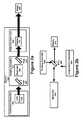
- FIG. 2 ais a block diagram illustrating an example of different assemblies, components, and light that can be present in the operation of the system.
- FIG. 2 bis a block diagram similar to FIG. 2 a , except that the disclosed system also includes a tracking assembly (which can also be referred to as a sensor assembly) and an augmentation assembly
- FIG. 2 cis a hierarchy diagram illustrating an example of different components that can be included in an illumination assembly.
- FIG. 2 dis a hierarchy diagram illustrating an example of different components that can be included in an imaging assembly.
- FIG. 2 eis a hierarchy diagram illustrating an example of different components that can be included in a projection assembly.
- FIG. 2 fis a hierarchy diagram illustrating an example of different components that can be included in the sensor assembly (which can also be referred to as a tracking assembly).
- FIG. 2 gis hierarchy diagram illustrating examples of different types of supporting components that can be included in the structure and function of the system.
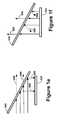
- FIG. 3 ais diagram of a perspective view of a VRD apparatus embodiment of the system.
- FIG. 3 bis environmental diagram illustrating an example of a side view of a user wearing a VRD apparatus embodying the system.
- FIG. 3 cis a configuration diagram illustrating an example of the components that can be used in a VRD apparatus.
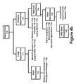
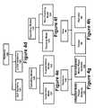
- FIG. 4 ais a hierarchy diagram illustrating an example of the different categories of display systems that the innovative system can be potentially be implemented in, ranging from giant systems such as stadium scoreboards to VRD visor systems that project visual images directly on the retina of an individual user.
- FIG. 4 bis a hierarchy diagram illustrating an example of different categories of display apparatuses.
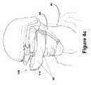
- FIG. 4 cis a perspective view diagram illustrating an example of user wearing a VRD visor apparatus.
- FIG. 4 dis hierarchy diagram illustrating an example of different display/projection technologies that can be incorporated into the system, such as DLP-based applications.
- FIG. 4 eis a hierarchy diagram illustrating an example of different operating modes of the system pertaining to immersion and augmentation.
- FIG. 4 fis a hierarchy diagram illustrating an example of different operating modes of the system pertaining to the use of sensors to detect attributes of the user and/or the user's use of the system.
- FIG. 4 gis a hierarchy diagram illustrating an example of different categories of system implementation based on whether or not the device(s) are integrated with media player components.
- FIG. 4 his hierarchy diagram illustrating an example of two roles or types of users, a viewer of an image and an operator of the system.
- FIG. 4 iis a hierarchy diagram illustrating an example of different attributes that can be associated with media content.
- FIG. 4 jis a hierarchy diagram illustrating examples of different contexts of images.
- the inventionis an apparatus, system, and method (collectively the “system”) that can display an image to a viewer. More specifically, the system can utilize a plate that is partially transmissive and partially reflective in lieu of expensive prisms such as TIR or RTIR prisms to direct light to and from a DMD. All element numbers referenced in the text below are referenced in Table 1 provided further below.
- Any image display system or devicecan be divided into at least three primary components: (1) an illumination assembly that provides light the light in which to form an image; (2) an imaging assembly that modulates that light into what will become the displayed image; and (3) a projection assembly that projects the modulated light to an intended destination where it can be accessed by one or more viewers.
- the third step of projecting the modulated lighttypically involves focusing the light and other processes which modify the light in certain respects.
- the image generated by the imaging assemblyis actually only an interim image, since the light comprising the image will be modified in certain ways in the time between it leaves the imaging assembly and reaches the eyes of a viewer.
- any image display deviceis the imaging assembly. That is where a modulator transforms light generated by a light source into something a viewer will want to see.
- modulatorsinclude DMDs, LCOS panels, and LCD panels.
- a DMDis a reflection-based light modulator. DMD stands for
- FIG. 1 ais a block diagram illustrating an example of prior art approach to the display of an image.
- the illumination assembly 200generates light 800 . That light encounters a configuration of two prisms 310 which collectively direct the unmodulated light 800 from the illumination assembly 200 towards the DMD 324 and the modulated light 800 from the DMD towards the projection assembly 400 so that the image 880 can be accessed by one or more viewers 96 .
- FIG. 1 ais shows the pathway of light 800 that makes it into the image 880 , not the light that is lost during the process. As illustrated in FIG.
- FIG. 1 bis a block diagram illustrating an alternative to the prior art approach of FIG. 1 a .
- a plate 340 with both reflective 372 and transmissive 374 propertiesis used to direct unmodulated light 800 to the DMD 324 .
- the optical chain 870(which can also be referred to as an optical pathway 870 ) of light 800 that actually reaches is illustrated in unbroken lines.
- FIG. 1 aIn contrast to FIG. 1 a where light 800 is reflected towards the modulator 320 by the juncture between the two prisms 310 , it is the surface of the plate 340 that reflects the light 800 towards the modulator 320 in FIG. 1 b .
- the light 800 represented by the downward arrow pointing towards the modular 320illustrates light 800 that encountered the reflective 372 characteristics of the plate 340 .
- the light 800 represented by the upward arrow from the modulator 320 through the plate 340 to the projection assembly 400represents modulated light 800 that encountered the transmissive 374 aspects of the plate 340 .
- the plate 340functions as both a reflector of light 800 as well as a transparent object through which light 800 passes through.
- FIG. 1 cis a somewhat less simplified version of FIG. 1 b in that some of the lost light 800 is illustrated in the Figure.
- the dotted horizontal line pointing to the rightrepresents light 800 that was transmitted through the plate 340 rather than being deflected by it. That light 800 is lost to the process of forming an image.
- the dotted line from the plate 340 directed downwards at an angle towards the DMD 324represents modulated light 800 from the DMD 324 that was reflected back rather than transmitted through the plate 340 .
- FIG. 1 dis a flow chart of a method 900 for displaying an image 880 that utilizes a plate 340 .
- the system 100generates light 800 utilizing an illumination assembly 200 . That light 800 reaches the plate 340 . Some of the light from 910 is lost through the transmissive 374 aspects of the plate 340 , while other rays of light 910 from 910 are reflected at 922 towards the modulator 320 .
- the modulator 320modulates the light 800 , forming an interim image 850 that is directed back to the plate 340 . Some of that light 800 is lost through the reflective 372 characteristics of the plate 340 while other rays of light 800 are transmitted at 926 for inclusion in the image 880 that is displayed to viewers 96 .
- the plate 340can be comprised of glass 342 , plastic film 344 , or combinations of both glass 342 and plastic 344 . Some embodiments of the plate 344 can involve multiple layers 346 as well as various coatings 348 .
- the plate 340can be implemented as a dynamic plate 341 .
- Plastic film 344 embodiments of the plate 340can be implemented as modulated film 345 in some embodiments.
- the plate 340can be implemented with an aperture 350 and even dynamic apertures 352 that are changed on an image to image basis.
- Plates 340can involve a variety of different gradients 360 , including adjustable gradients 362 such as adjustable diffractive gradients 364 .
- Different plates 340can have different magnitudes of reflectiveness 372 and transmissiveness 374 .
- Some plates 340can impact the polarization 373 of light 800 that reaches the plate 340 .
- Adjustable gradients 362can be used to implement desirable optical effects 380 .
- the plate 340can include holographic elements 382 , and be embodied in as a micro lens array 384 .
- the plate 340can also be embodied in as a collapsible plate 340 so that the plate 340 takes up less room when the system 100 is not displaying images 880 .
- the plate 340can involve different magnitudes of reflectiveness 372 , transmissiveness 374 , and polarization 373 , but such characteristics can also vary with respect to where the light 800 falls on the spectrum 802 light wavelengths. Some embodiments can involve uniform attributes across a full spectrum 803 of light 803 . Other embodiments may differentiate between infrared 806 , ultraviolet 807 , visible light 804 , or even within a partial spectrum of visible light 804 .
- FIGS. 1 e and 1 fillustrate examples of a plate 340 that is approximately 50% reflective 372 and 50% transmissive 374 . Many embodiments will involve ranges between about 60/40% and 40/60%. However, the system 100 can be implemented far outside those ranges.
- FIGS. 1 g and 1 lillustrate examples of the system 100 using a plate 340 to display an image 880 .
- FIGS. 1 h and 1 millustrate corresponding examples of such a plate 340 in compressed mode 128 , where the plate 340 is collapsed to save space while the system 100 is not being used to display images 880 .
- FIG. 1 nis an example of the different assemblies and components that can utilize the plate 340 to perform the function of a “traffic cop” with respect to the flow of light 800 .
- FIG. 2 ais a block diagram of a system 100 comprised of an illumination assembly 200 that supplies light 800 to an imaging assembly 300 .
- a modulator 320 of the imaging assembly 300uses the light 800 from the illumination assembly 200 to create the image 880 that is displayed by the system 100 .
- the diagramis from the point of view of a pathway of light 800 that forms the image 880 , so the plate 340 appears twice within the imaging assembly 300 because light 800 touches the plate 340 before reaching the modulator 320 and after leaving the modulator 320 .
- the system 100can also include a projection assembly 400 that directs the image 880 from the imaging assembly 300 to a location where it can be accessed by one or more users 90 , a display 410 .
- the image 880 generated by the imaging assembly 300will often be modified in certain ways before it is displayed by the system 100 to users 90 , and thus the image generated by the imaging assembly 300 can also be referred to as an interim image 850 or a work-in-process image 850 .
- An illumination assembly 200performs the function of supplying light 800 to the system 100 so that an image 880 can be displayed.
- the illumination assembly 200can include a light source 210 for generating light 800 .
- the illumination assembly 200generates the light 800 that is used and processed by other assemblies of the system 100 .
- FIG. 2 cis a hierarchy diagram illustrating an example of different components that can be included in the illumination assembly 200 .
- Those componentscan include but are not limited a wide range of light sources 210 , a diffuser assembly 280 , and a variety of supporting components 150 .
- Examples of light sources 210can include but are such as a multi-bulb light source 211 , an LED lamp 212 , a 3 LED lamp 213 , a laser 214 , an OLED 215 , a CFL 216 , an incandescent lamp 218 , and a non-angular dependent lamp 219 .
- the light source 210is where light 800 is generated and moves throughout the rest of the system 100 . Thus, each light source 210 is a location 230 for the origination of light 800 .
- a 3 LED lampas a light source, which one LED designated for each primary color of red, green, and blue.
- An imaging assembly 300performs the function of creating the image 880 from the light 800 supplied by the illumination assembly 200 .
- a modulator 320can transform the light 800 supplied by the illumination assembly 200 into the image 880 that is displayed by the system 100 .
- the image 880 generated by the imaging assembly 300can sometimes be referred to as an interim image 850 because the image 850 may be focused or otherwise modified to some degree before it is directed to the location where it can be experienced by one or more users 90 .
- Imaging assemblies 300can vary significantly based on the type of technology used to create the image. Display technologies such as DLP (digital light processing), LCD (liquid-crystal display), LCOS (liquid crystal on silicon), and other methodologies can involve substantially different components in the imaging assembly 300 .
- DLPdigital light processing
- LCDliquid-crystal display
- LCOSliquid crystal on silicon
- FIG. 2 fis a hierarchy diagram illustrating an example of some of the different components that can be utilized in the imaging assembly 300 for the system 100 .
- a prism 310can be very useful component in directing light to and/or from the modulator 320 .
- DLP applicationswill typically use an array of TIR prisms 311 or RTIR prisms 312 to direct light to and from a DMD 324 .
- the plate 340can replace the need for prisms 310 used in the system 100 .
- a modulator 320(sometimes referred to as a light modulator 320 ) is the device that modifies or alters the light 800 , creating the image 880 that is to be displayed. Modulators 320 can operate using a variety of different attributes of the modulator 320 .
- a reflection-based modulator 322uses the reflective-attributes of the modulator 320 to fashion an image 880 from the supplied light 800 . Examples of reflection-based modulators 322 include but are not limited to the DMD 324 of a DLP display and some LCOS (liquid crystal on silicon) panels 340 .
- a transmissive-based modulator 321uses the transmissive-attributes of the modulator 320 to fashion an image 880 from the supplied light 800 .
- transmissive-based modulators 321include but are not limited to the LCD (liquid crystal display) 330 of an LCD display and some LCOS panels 340 .
- the imaging assembly 300 for an LCOS or LCD system 100will typically have a combiner cube or some similar device for integrating the different one-color images into a single image 880 .
- the imaging assembly 300can also include a wide variety of supporting components 150 .
- a projection assembly 400can perform the task of directing the image 880 to its final destination in the system 100 where it can be accessed by users 90 .
- the image 880 created by the imaging assembly 300will be modified in at least some minor ways between the creation of the image 880 by the modulator 320 and the display of the image 880 to the user 90 .
- the image 880 generated by the modulator 320 of the imaging assembly 400may only be an interim image 850 , not the final version of the image 880 that is actually displayed to the user 90 .
- FIG. 2 eis a hierarchy diagram illustrating an example of different components that can be part of the projection assembly 400 .
- a display 410is the final destination of the image 880 , i.e. the location and form of the image 880 where it can be accessed by users 90 .
- Examples of displays 410can include an active screen 412 , a passive screen 414 , an eyepiece 416 , and a VRD eyepiece 418 .
- the projection assembly 400can also include a variety of supporting components 150 as discussed below.
- a plate 340can also serve as a component within the projection assembly 400 because the plate 340 is an excellent tool for managing the flow of light 800 between different system 100 components, as illustrated in FIG. 2 b.
- FIG. 2 billustrates an example of the system 100 that includes a tracking assembly 500 (which is also referred to as a sensor assembly 500 ).
- the sensor assembly 500can be used to capture information about the user 90 , the user's interaction with the image 880 , and/or the exterior environment in which the user 90 and system 100 are physically present.
- the sensor assembly 500can include a sensor 510 , typically a camera such as an infrared camera for capturing an eye-tracking attribute 530 pertaining to eye movements of the viewer 96 .
- a lamp 520such as an infrared light source to support the functionality of the infrared camera, and a variety of different supporting components 150 .
- the tracking assembly 500will utilize components of the projection assembly 400 such as the configuration of a curved mirror 420 operating in tandem with a partially transparent plate 340 . Such a configuration can be used to capture infrared images of the eye 92 of the viewer 96 while simultaneously delivering images 880 to the eye 92 of the viewer 96 .
- the sensor assembly 500can also include sensors 510 intended to capture visual images, video, sounds, motion, position, and other information from the operating environment 80 .
- An augmentation assembly 600can allow natural light from the exterior environment 80 in through a window component 620 in the system 100 (the window component 620 can include a shutter component 610 ) that is capable of being opened or closed.
- FIG. 2 jis a hierarchy diagram illustrating an example of some supporting components 150 , many of which are conventional optical components. Any display technology application will involve conventional optical components such as mirrors 141 (including dichroic mirrors 152 ) lenses 160 , collimators 170 , and plates 180 . Similarly, any powered device requires a power source 191 and a device capable of displaying an image 880 is likely to have a processor 190 .
- the system 100can be implemented with respect to a wide variety of different display technologies 140 , including DLP systems 141 , LCD systems 142 , and LCOS system 143 .
- the various drawingsfocus on DLP systems 141 because it is believed that the plate 340 is particularly useful as a substitute for TIR prisms 311 and RTIR prisms 312 .
- FIG. 3 ais a perspective diagram illustrating an example of a VRD visor apparatus 116 .
- Two VRD eyepieces 418provide for directly projecting the image 880 onto the eyes of the user 90 .
- FIG. 3 bis a side view diagram illustrating an example of a VRD visor apparatus 116 being worn on the head 94 of a user 90 .
- the eyes 92 of the user 90are blocked by the apparatus 116 itself, with the apparatus 116 in a position to project the image 880 on the eyes 92 of the user 90 .
- FIG. 3 cis a component diagram illustrating an example of a VRD visor apparatus 116 for the left eye 92 .
- a mirror image of FIG. 3 cwould pertain to the right eye 92 .
- a 3 LED light source 213generates the light which passes through a condensing lens 160 that directs the light 800 to a mirror 151 which reflects the light 800 to a shaping lens 160 prior to the entry of the light 800 into an imaging assembly 300 comprised of a plate 340 and a DMD 324 .
- the interim image 850 from the imaging assembly 300passes through another lens 160 that focuses the interim image 850 into a final image 880 that is viewable to the user 90 through the eyepiece 416 .
- the system 100represents a substantial improvement over prior art display technologies. Just as there are a wide range of prior art display technologies, the system 100 can be similarly implemented in a wide range of different ways.
- the innovation of using a plate 340 in lieu of prisms 340 to direct light 800be implemented at a variety of different scales, utilizing a variety of different display technologies, in both immersive and augmenting contexts, and in both one-way (no sensor feedback from the user 90 ) and two-way (sensor feedback from the user 90 ) embodiments.
- Display devicescan be implemented in a wide variety of different scales.
- the monster scoreboard at EverBanks Field(home of the Jacksonville Jaguars) is a display system that is 60 feet high, 362 feet long, and comprised of 35.5 million LED bulbs. The scoreboard is intended to be viewed simultaneously by tens of thousands of people.
- the GLYPHTM visor by Avegant Corporationis a device that is worn on the head of a user and projects visual images directly in the eyes of a single viewer. Between those edges of the continuum are a wide variety of different display systems.
- the system 100displays visual images 808 to users 90 with enhanced light with reduced coherence.
- the system 100can be potentially implemented in a wide variety of different scales.
- FIG. 4 ais a hierarchy diagram illustrating various categories and subcategories pertaining to the scale of implementation for display systems generally, and the system 100 specifically. As illustrated in FIG. 4 a , the system 100 can be implemented as a large system 101 or a personal system 103
- a large system 101is intended for use by more than one simultaneous user 90 .
- Examples of large systems 101include movie theater projectors, large screen TVs in a bar, restaurant, or household, and other similar displays.
- Large systems 101include a subcategory of giant systems 102 , such as stadium scoreboards 102 a , the Time Square displays 102 b , or other or the large outdoor displays such as billboards off the expressway.
- a personal system 103is an embodiment of the system 100 that is designed to for viewing by a single user 90 .
- Examples of personal systems 103include desktop monitors 103 a , portable TVs 103 b , laptop monitors 103 c , and other similar devices.
- the category of personal systems 103also includes the subcategory of near-eye systems 104 .
- a near-eye system 104is a subcategory of personal systems 103 where the eyes of the user 90 are within about 12 inches of the display.
- Near-eye systems 104include tablet computers 104 a , smart phones 104 b , and eye-piece applications 104 c such as cameras, microscopes, and other similar devices.
- the subcategory of near-eye systems 104includes a subcategory of visor systems 105 .
- a visor system 105is a subcategory of near-eye systems 104 where the portion of the system 100 that displays the visual image 200 is actually worn on the head 94 of the user 90 .
- Examples of such systems 105include virtual reality visors, Google Glass, and other conventional head-mounted displays 105 a .
- the category of visor systems 105includes the subcategory of VRD visor systems 106 .
- a VRD visor system 106is an implementation of a visor system 105 where visual images 200 are projected directly on the eyes of the user.
- the technology of projecting images directly on the eyes of the vieweris disclosed in a published patent application titled “IMAGE GENERATION SYSTEMS AND IMAGE GENERATING METHODS” (U.S. Ser. No. 13/367,261) that was filed on Feb. 6, 2012, the contents of which are hereby incorporated by reference.
- FIG. 4 bis a hierarchy diagram illustrating an example of different categories and subcategories of apparatuses 110 .
- FIG. 4 bclosely mirrors FIG. 5 a .
- the universe of potential apparatuses 110includes the categories of large apparatuses 111 and personal apparatuses 113 .
- Large apparatuses 111include the subcategory of giant apparatuses 112 .
- the category of personal apparatuses 113includes the subcategory of near-eye apparatuses 114 which includes the subcategory of visor apparatuses 115 .
- VRD visor apparatuses 116comprise a category of visor apparatuses 115 that implement virtual retinal displays, i.e. they project visual images 200 directly into the eyes of the user 90 .
- FIG. 4 cis a diagram illustrating an example of a perspective view of a VRD visor system 106 embodied in the form of an integrated VRD visor apparatus 116 that is worn on the head 94 of the user 90 . Dotted lines are used with respect to element 92 because the eyes 92 of the user 90 are blocked by the apparatus 116 itself in the illustration.
- FIG. 4 dis a hierarchy diagram illustrating different categories of the system 100 based on the underlying display technology in which the system 200 can be implemented.
- the system 100is intended for use as a DLP system 141 , but could be potentially be used as an LCOS system 143 or even an LCD system 142 although the means of implementation would obviously differ and the reasons for implementation may not exist.
- the system 100can also be implemented in other categories and subcategories of display technologies.
- FIG. 4 eis a hierarchy diagram illustrating a hierarchy of systems 100 organized into categories based on the distinction between immersion and augmentation.
- Some embodiments of the system 100can have a variety of different operating modes 120 .
- An immersion mode 121has the function of blocking out the outside world so that the user 90 is focused exclusively on what the system 100 displays to the user 90 .
- an augmentation mode 122is intended to display visual images 200 that are superimposed over the physical environment of the user 90 .
- the distinction between immersion and augmentation modes of the system 100is particularly relevant in the context of near-eye systems 104 and visor systems 105 .
- system 100can be configured to operate either in immersion mode or augmentation mode, at the discretion of the user 90 . While other embodiments of the system 100 may possess only a single operating mode 120 .
- FIG. 4 fis a hierarchy diagram that reflects the categories of a one-way system 124 (a non-sensing operating mode 124 ) and a two-way system 123 (a sensing operating mode 123 ).
- a two-way system 123can include functionality such as retina scanning and monitoring. Users 90 can be identified, the focal point of the eyes 92 of the user 90 can potentially be tracked, and other similar functionality can be provided.
- a one-way system 124there is no sensor or array of sensors capturing information about or from the user 90 .
- Display devicesare sometimes integrated with a media player.
- a media playeris totally separate from the display device.
- a laptop computercan include in a single integrated device, a screen for displaying a movie, speakers for projecting the sound that accompanies the video images, a DVD or BLU-RAY player for playing the source media off a disk.
- Such a deviceis also capable of streaming
- FIG. 4 gis a hierarchy diagram illustrating a variety of different categories of systems 100 based on the whether the system 100 is integrated with a media player or not.
- An integrated media player system 107includes the capability of actually playing media content as well as displaying the image 880 .
- a non-integrated media player system 108must communicate with a media player in order to play media content.
- FIG. 4 his a hierarchy diagram illustrating an example of different roles that a user 90 can have.
- a viewer 96can access the image 880 but is not otherwise able to control the functionality of the system 100 .
- An operator 98can control the operations of the system 100 , but cannot access the image 880 .
- the viewers 96are the patrons and the operator 98 is the employee of the theater.
- media content 840can include a wide variety of different types of attributes.
- a system 100 for displaying an image 880is a system 100 that plays media content 840 with a visual attribute 841 .
- many instances of media content 840will also include an acoustic attribute 842 or even a tactile attribute.
- some images 880are parts of a larger video 890 context.
- an image 880can be stand-alone still frame 882 .
- Table 1sets forth a chart that correlates element numbers, element names, and element definitions/descriptions.
- the system 100can be implemented in outdoor environments 80 as well as indoor environments 80.
- Examples of operating environments 80can include but are not limited the inside a vehicle, such as a car, boat, or plane; large public places, such as an airport, park, shopping mall, auditorium, sports stadium, grocery store, or church; domestic environments such as a house, apartment, or hotel room; and work environments such as an office or factory.
- 90 User A user 90is a viewer 96 and/or operator 98 of the system 100.
- the user 90is typically a human being.
- users 90can be different organisms such as dogs or cats, or even automated technologies such as expert systems, artificial intelligence applications, and other similar “entities”.
- the eyeconsists of different portions including but not limited to the sclera, iris, cornea, pupil, and retina.
- Some embodiments of the system 100involve a VRD visor apparatus 116 that can project the desired image 880 directly onto the eye 92 of the user 90.
- 94 HeadThe portion of the body of the user 90 that includes the eye 92.
- Some embodiments of the system 100can involve a visor apparatus 115 that is worn on the head 94 of the user 90.
- 96 ViewerA user 90 of the system 100 who views the image 880 provided by the system 100. All viewers 96 are users 90 but not all users 90 are viewers 96. The viewer 96 does not necessarily control or operate the system 100.
- the viewer 96can be a passive beneficiary of the system 100, such as a patron at a movie theater who is not responsible for the operation of the projector or someone wearing a visor apparatus 115 that is controlled by someone else.
- 98 OperatorA user 90 of the system 100 who exerts control over the processing of the system 100. All operators 98 are users 90 but not all users 90 are operators 98.
- the operator 98does not necessarily view the images 880 displayed by the system 100 because the operator 98 may be someone operating the system 100 for the benefit of others who are viewers 96.
- the operator 98 of the system 100may be someone such as a projectionist at a movie theater or the individual controlling the system 100.
- System Acollective configuration of assemblies, subassemblies, components, processes, and/or data that provide a user 90 with the functionality of engaging in a media experience by accessing a media content unit 840.
- Some embodiments of the system 100can involve a single integrated apparatus 110 hosting all components of the system 100 while other embodiments of the system 100 can involve different non-integrated device configurations.
- Some embodiments of the system 100can be large systems 102 or even giant system 101 while other embodiments of the system 100 can be personal systems 103, such as near-eye systems 104, visor systems 105, and VRD visor systems 106.
- Systems 100can also be referred to as display systems 100. The system 100 is believed to be particularly useful in the context of personal system 103.
- Giant SystemAn embodiment of the system 100 intended to be viewed simultaneously by a thousand or more people. Examples of giant systems 101 include scoreboards at large stadiums, electronic billboards such the displays in Time Square in New York City, and other similar displays.
- a giant system 101is a subcategory of large systems 102.
- 102 Large SystemAn embodiment of the system 100 that is intended to display an image 880 to multiple users 90 at the same time.
- a large system 102is not a personal system 103.
- the media experience provided by a large system 102is intended to be shared by a roomful of viewers 96 using the same illumination assembly 200, imaging assembly 300, and projection assembly 400.
- Examples of large systems 102include but are not limited to a projector/screen configuration in a movie theater, classroom, or conference room; television sets in sports bar, airport, or residence; and scoreboard displays at a stadium. Large systems 101 can also be referred to as large display systems 101.
- Common examples of personal media systemsinclude desktop computers (often referred to as personal computers), laptop computers, portable televisions, and near-eye systems 104.
- Personal systems 103can also be referred to as personal media systems 103.
- Near- eye systems 104are a subcategory of personal systems 103.
- Examples of near-eye systems 103include but are not limited to tablet computers, smart phones, system 100 involving eyepieces, such as cameras, telescopes, microscopes, etc., and visor media systems 105, .
- Near-eye systems 104can also be referred to as near-eye media systems 104.
- Visor systems 105can also be referred to as visor display systems 105.
- VRD Visor System VRDstands for a virtual retinal display. VRDs can also be referred to as retinal scan displays (“RSD”) and as retinal projectors (“RP”). VRD projects the image 880 directly onto the retina of the eye 92 of the viewer 96.
- a VRD Visor System 106is a visor system 105 that utilizes a VRD to display the image 880 on the eyes 92 of the user 90.
- a VRD visor system 106can also be referred to as a VRD visor display system 106.
- 110 ApparatusA device that provides a user 90 with the ability to engage in a media experience 840, i.e.
- the apparatus 110can be partially or even fully integrated with a media player 848. Many embodiments of the apparatus 110 will have a capability to communicate both acoustic attributes 842 and visual attributes 841 of the media experience 840 to the user 90.
- the apparatus 110can include the illumination assembly 200, the imaging assembly 300, and the projection assembly 400.
- the apparatus 110includes the media player 848 that plays the media content 840. In other embodiments, the apparatus 110 does not include the media player 848 that plays the media content 840.
- Different configurations and connection technologiescan provide varying degrees of “plug and play” connectivity that can be easily installed and removed by users 90.
- 111 Giant ApparatusAn apparatus 110 implementing an embodiment of a giant system 101.
- a giant apparatus 111include the scoreboards at a professional sports stadium or arena.
- Common examples of large apparatuses 111include movie theater projectors and large screen television sets.
- a large apparatus 111is typically positioned on a floor or some other support structure.
- a large apparatus 111such as a flat screen TV can also be mounted on a wall.
- 113Personal Media An apparatus 110 implementing an embodiment of a personal Apparatus system 103.
- Many personal apparatuses 112are highly portable and are supported by the user 90.
- Other embodiments of personal media apparatuses 113are positioned on a desk, table, or similar surface.
- 114Near-Eye An apparatus 110 implementing an embodiment of a near-eye Apparatus system 104. Many near-eye apparatuses 114 are either worn on the head (are visor apparatuses 115) or are held in the hand of the user 90. Examples of near-eye apparatuses 114 include smart phones, tablet computers, camera eye-pieces and displays, microscope eye-pieces and displays, gun scopes, and other similar devices.
- the visor apparatus 115is worn on the head 94 of the user 90.
- the visor apparatus 115can also be referred simply as a visor 115.
- VRD VisorAn apparatus 110 in a VRD visor system 106.
- the VRD visor apparatus 115includes a virtual retinal display that projects the visual image 200 directly on the eyes 92 of the user 90.
- a VRD visor apparatus 116is disclosed in U.S. Pat. No. 8,982,014, the contents of which are incorporated by reference in their entirety.
- 120 Operating ModesSome embodiments of the system 100 can be implemented in such a way as to support distinct manners of operation. In some embodiments of the system 100, the user 90 can explicitly or implicitly select which operating mode 120 controls. In other embodiments, the system 100 can determine the applicable operating mode 120 in accordance with the processing rules of the system 100.
- the system 100is implemented in such a manner that supports only one operating mode 120 with respect to a potential feature.
- some systems 100can provide users 90 with a choice between an immersion mode 121 and an augmentation mode 122, while other embodiments of the system 100 may only support one mode 120 or the other.
- the act of watching a movieis intended to be an immersive experience.
- AugmentationAn operating mode 120 of the system 100 in which the image 880 displayed by the system 100 is added to a view of the physical environment of the user 90, i.e. the image 880 augments the real world.
- Google Glassis an example of an electronic display that can function in an augmentation mode.
- 126 SensingAn operating mode 120 of the system 100 in which the system 100 captures information about the user 90 through one or more sensors. Examples of different categories of sensing can include eye tracking pertaining to the user's interaction with the displayed image 880, biometric scanning such as retina scans to determine the identity of the user 90, and other types of sensor readings/measurements.
- the system 100can be Technology implemented using a wide variety of different display technologies. Examples of display technologies 140 include digital light processing (DLP), liquid crystal display (LCD), and liquid crystal on silicon (LCOS). Each of these different technologies can be implemented in a variety of different ways.
- DLPdigital light processing
- LCDliquid crystal display
- LCOSliquid crystal on silicon
- a system 100 like any Components electronic displayis a complex combination of components and processes. Light 800 moves quickly and continuously through the system 100.
- Various supporting components 150are used in different embodiments of the system 100. A significant percentage of the components of the system 100 can fall into the category of supporting components 150 and many such components 150 can be collectively referred to as “conventional optics”.
- Supporting components 150can be necessary in any implementation of the system 100 in that light 800 is an important resource that must be controlled, constrained, directed, and focused to be properly harnessed in the process of transforming light 800 into an image 880 that is displayed to the user 90.
- the text and drawings of a patentare not intended to serve as product blueprints.
- One of ordinary skill in the artcan devise multiple variations of supplementary components 150 that can be used in conjunction with the innovative elements listed in the claims, illustrated in the drawings, and described in the text.
- 151 MirrorAn object that possesses at least a non-trivial magnitude of reflectivity with respect to light. Depending on the context, a particular mirror could be virtually 100% reflective while in other cases merely 50% reflective.
- Mirrors 151can be comprised of a wide variety of different materials, and configured in a wide variety of shapes and sizes.
- 152Dichroic Mirror A mirror 151 with significantly different reflection or transmission properties at two different wavelengths.
- 160 LensAn object that possesses at least a non-trivial magnitude of transmissivity. Depending on the context, a particular lens could be virtually 100% transmissive while in other cases merely about 50% transmissive.
- a lens 160is often used to focus and/or light 800.
- ProcessorA central processing unit (CPU) that is capable of carrying out the instructions of a computer program.
- the system 100can use one or more processors 190 to communicate with and control the various components of the system 100.
- Power SourceA source of electricity for the system 100.
- power sourcesinclude various batteries as well as power adaptors that provide for a cable to provide power to the system 100.
- Different embodiments of the system 100can utilize a wide variety of different internal and external power sources. 191. Some embodiments can include multiple power sources 191.
- 211 Multi-Prong LightA light source 210 that includes more than one illumination Source element.
- a 3-colored LED lamp 213is a common example of a multi-prong light source 212.
- LED Lamp A light source 210comprised of a light emitting diode (LED).
- 213 3 LED Lamp A light source 210comprised of three light emitting diodes (LEDs). In some embodiments, each of the three LEDs illuminates a different color, with the 3 LED lamp eliminating the use of a color wheel.
- Laser A light source 210comprised of a device that emits light through a process of optical amplification based on the stimulated emission of electromagnetic radiation.
- OLED Lamp A light source 210comprised of an organic light emitting diode (OLED).
- CFL Lamp A light source 210comprised of a compact fluorescent bulb.
- Incandescent A light source 210comprised of a wire filament heated to a high Lamp temperature by an electric current passing through it.
- Non-Angular A light source 210that projects light that is not limited to a specific Dependent Lamp angle.
- Arc Lamp A light source 210that produces light by an electric arc.
- 230 Light LocationA location of a light source 210, i.e. a point where light originates. Configurations of the system 100 that involve the projection of light from multiple light locations 230 can enhance the impact of the diffusers 282.
- 300 ImagingA collective assembly of components, subassemblies, processes, Assembly and light 800 that are used to fashion the image 880 from light 800.
- the image 880 initially fashioned by the imaging assembly 300can be modified in certain ways as it is made accessible to the user 90.
- the modulator 320is the component of the imaging assembly 300 that is primarily responsible for fashioning an image 880 from the light 800 supplied by the illumination assembly 200.
- 310 PrismA substantially transparent object that often has triangular bases.
- Some display technologies 140utilize one or more prisms 310 to direct light 800 to a modulator 320 and to receive an image 880 or interim image 850 from the modulator 320.
- Prisms 310function as “traffic cops” for directing light 800 to the modular 320 so that the light 800 can be modulated.
- prisms 310direct light away from the modulator 320 and towards the next step in the optic pathway 870.
- 320 Modulator or LightA device that regulates, modifies, or adjusts light 800.
- Modulators Modulator 320form an image 880 or interim image 850 from the light 800 supplied by the illumination assembly 200.
- Common categories of modulators 320include transmissive-based light modulators 321 and reflection-based light modulators 322.
- 321Transmissive- A modulator 320 that fashions an image 880 from light 800 utilizing Based Light a transmissive property of the modulator 320.
- LCDsare a common Modulator example of a transmissive-based light modulator 321.
- 322Reflection-Based A modulator 320 that fashions an image 880 from light 800 utilizing Light Modulator a reflective property of the modulator 320.
- Common examples of reflection-based light modulators 322include DMDs 324 and LCOSs 340. 324 DMD A reflection-based light modulator 322 commonly referred to as a digital micro mirror device.
- a DMD 324is typically comprised of a several thousand microscopic mirrors arranged in an array on a processor 190, with the individual microscopic mirrors corresponding to the individual pixels in the image 880.
- 326 LCD Panel or LCDA light modulator 320 in an LCD (liquid crystal display).
- a liquid crystal displaythat uses the light modulating properties of liquid crystals.
- Each pixel of an LCDtypically consists of a layer of molecules aligned between two transparent electrodes, and two polarizing filters (parallel and perpendicular), the axes of transmission of which are (in most of the cases) perpendicular to each other. Without the liquid crystal between the polarizing filters, light passing through the first filter would be blocked by the second (crossed) polarizer.
- An LCOS 244can be transmissive or reflective.
- 330Dichroid Combiner A device used in an LCOS or LCD display that combines the Cube different colors of light 800 to formulate an image 880 or interim image 850.
- the dichroid combiner cube 330can be an equivalent to a prism 310 in the context of an LCOS system 142 or an LCD system 143.
- the plate 340Plate A substrate of material that possess some magnitude of reflectiveness 372 and some magnitude of transmissiveness 374. Some embodiments of the plate 340 can also impact the polarization 373 of light 800. In some embodiments, the optical effects of the plate 340 can substantially equal across the spectrum 802 of light 800. In other embodiments, there can be vastly different optical effects in different ranges of the spectrum 802.
- the plate 340can be implemented using a wide variety of materials such as glass 342 or plastic film 344. 341 Dynamic Plate A plate 340 for which the optical characteristics of transmissiveness 373, reflectiveness 374, and/or polarization 373 can be modified across the entire spectrum 802 or for specific ranges within the spectrum 802 while the system 100 is generating images 880.
- the plate 340can change its characteristics on an image by image or even subframe by subframe basis.
- 342 GlassA substantially hard and brittle substance, typically with transparent or translucent, made by fusing sand with soda, lime, and other ingredients that is rapidly cooled.
- Many embodiments of the plate 340include a glass 342 component. Some embodiments of the plate 340 are comprised substantially or even entirely of glass 342.
- 344 Plastic FilmA synthetic material made from a wide range of polymers. Plastic film 344 can also be referred to simply as plastic 344.
- Many embodiments of the plate 340can include a plastic 344 component 345 Modulated Film A plastic film 344 that modulates the light 800 that comes into contact with the film 345.
- modulated films 345include electrochromic, photochromic, and other types. Such films can be used to create a dynamic aperture 352 with desirable optical effects 860.
- 346Layer A substrate of material that comprises the plate 340.
- the plate 340can be comprised of one or more layers 346.
- 348Coating A covering applied to a surface, such as a plate 340. Coatings can be comprised of glass 342, plastic film 344, and/or other components with desirable reflectiveness 372, polarization 373, and/or transmissiveness 374 attributes.
- 350Aperture A hole or opening.
- the plate 340can include one or more apertures 350 to facilitate the transmission of light 800 though the aperture 350.
- 362Adjustable A gradient 360 that provides for being dynamically modified while Gradient the system 100 is generating images 880.
- 364Adjustable An adjustable gradient 362 where the function and purpose of the Diffractive adjustable gradient 362 is to address the diffraction of light 800.
- Gradient 372 Reflectivenessor The extent to which an object such as a plate 340 causes light 800 Reflectivity to reflect back.
- the plate 340will possess a level of reflectiveness 372 such that between about 40%-60% of light 800 striking the plate 340 to be reflected back.
- a plate 340 possessing a reflectivity of about 50%is desirable in many embodiments of the system 100.
- the system 100can be implemented with a plate 340 possessing a wide variety of different magnitudes of reflectiveness 372 ranging from as little as about 0.5% up to about 99.5%.
- the reflectivity 372 of the plate 340 or other component of the system 100can differentiate light 800 on the basis of the wavelength of the applicable light 800 (i.e. where in the light 800 falls in the spectrum 802.
- the plate 340can be less reflective 372 in the infrared spectrum 806 than in the visual spectrum 804 to facilitate eye-tracking functionality performed by the system 100.
- 373 Polarization or Polarized light 800is light 800 traveling in a substantially uniform Polarity orientation in which the vibrations in the light waves occur in a single place.
- Light 800can be polarized through transmission 374, through reflection 372, through refraction, or by scattering.
- the plate 340can impact the polarity 373 of the light 800 that the plate comes into contact with.
- 374 TransmissivenessThe extent to which an object such as a plate 340 allows light 800 or to pass through the object.
- Transmissivity the plate 340will possess a level of transmissivity 374 such that between about 40%-60% of light 800 striking the plate 340 can pass through.
- a plate 340 possessing a transmissiveness of about 50%is desirable in many embodiments of the system 100.
- the system 100can be implemented with a plate 340 possessing a wide variety of different magnitudes of transmissivity 374 ranging from as little as about 0.5% up to about 99.5%.
- 380 Optical EffectA modification to the displayed image 880 that is desirable based on the context of the displayed image 800. By way of example, in augmentation mode 122 a desired optical effect 380 may be shading to create the color black in the image 880.
- the plate 340can include or be comprised of one or more Element holographic elements 382.
- a holographic element 382is an optical component, such as a lens, filter, beam splitter, or diffraction grating.
- a holographic element 382can be produced using holographic imaging processes or principles. Dichromated gelatin and photoresist are among the holographic recording materials used in forming holographic elements 382.
- 384 Micro Lens ArrayThe plate 340 can include or be comprised of an array of very small lenses.
- a micro lens array 384can also be referred to as a textured plated 384.
- 400 ProjectionA collection of components used to make the image 880 Assembly accessible to the user 90.
- the projection assembly 400includes a display 410.
- the projection assembly 400can also include various supporting components 150 that focus the image 880 or otherwise modify the interim image 850 transforming it into the image 880 that is displayed to one or more users 90.
- the projection assembly 400can also be referred to as a projection subsystem 400.
- 410Display or Screen An assembly, subassembly, mechanism, or device by which the image 880 is made accessible to the user 90.
- Examples of displays 410include active screens 412, passive screens 414, eyepieces 416, and VRD eyepieces 418.
- 412 Active Screen A display screen 410powered by electricity that displays the image 880.
- a conventional movie theater screenis a common example of a passive screen 412.
- 416 Eyepiece A display 410positioned directly in front of the eye 92 of an individual user 90.
- 418VRD Eyepiece or An eyepiece 416 that provides for directly projecting the image 880 VRD Display on the eyes 92 of the user 90.
- a VRD eyepiece 418can also be referred to as a VRD display 418.
- the curved mirror 420can perform additional functions in embodiments of the system 100 that include a sensing mode 126 and/or an augmentation mode 122.
- 500 Sensor AssemblyThe sensor assembly 500 can also be referred to as a tracking assembly 500.
- the sensor assembly 500is a collection of components that can track the eye 92 of the viewer 96 while the viewer 96 is viewing an image 880.
- the tracking assembly 500can include an infrared camera 510, and infrared lamp 520, and variety of supporting components 150.
- the assembly 500can also include a quad photodiode array or CCD.
- the 510Sensor A component that can capture an eye-tracking attribute 530 from the eye 92 of the viewer 96.
- the sensor 510is typically a camera, such as an infrared camera.
- 511 External Camera A sensor 510that captures images of the exterior operating environment 80.
- 512Microphone A sensor 510 that captures sounds of the exterior operating environment 80.
- Motion Sensor A sensor 510that detects motion in the operating environment 80.
- 514Position Sensor A sensor 510 that identifies a location of the apparatus 110.
- a light sourceis typically very helpful.
- the lamp 520is an infrared lamp and the camera is an infrared camera.
- Eye-TrackingAn attribute pertaining to the movement and/or position of the eye Attribute 92 of the viewer 96.
- Some embodiments of the system 100can be configured to selectively influence the focal point 870 of light 800 in an area of the image 880 based on one or more eye-tracking attributes 530 measured or captured by the sensor assembly 500.
- Output DevicesA device or component that communicates some aspect of the media experience 840 to the user 90.
- the system 100can utilize a wide variety of output devise 550, many of which may be stand- alone, non-integrated, plug and play types of components. Common examples of output devices 550 include speakers 560 and displays 410.
- 620Window A passageway for light from the exterior environment in an embodiment that is not fully immersive.
- 650 Exterior LightThe surroundings of the system 100 or apparatus 110. Some embodiments of the system 100 can factor in lighting conditions of the exterior environment 650 in supplying light 800 for the display of images 880.
- 700 ParametersAn at least substantially comprehensive compilation of different ways in which the apparatus 110 can operate. The particular configuration 705 of parameters 700 that will be operable at any particular time will depend on the defining of one or more triggers 750. Examples of categories of parameters 700 include but are not limited to a sound parameter 710, a display parameter 720, a progression parameter 730, and a haptic parameter 740. 705 Configuration A subset of operating parameters 700 from the universe of potential operating parameters 700.
- Different triggers 750can result in different configurations 705.
- the system 100can be implemented to facilitate automatic changes from one configuration 705 of parameters 700 to another configuration 705 of parameters 700 based on or more triggers 750.
- 710Sound Parameters
- Examples of sound parameters 710can include but are not limited to an off/mute 711, a temporarily reduced volume 712, an alert 713, an external sound amplification 714, a message 715, an ongoing volume change 716.
- 711 Off/MuteThe sound parameter 710 where sound ceases to be communicated by the system 100 to the user 90.
- Examples of display parameters 720can include but are not limited to an off 721, a dimmed display 722, an an/external view 723, an on/augmented view 724, a flash 725, a verbal alert 726, and an in increased brightness 727.
- Display parameters 720can be temporary (for a pre-defined period of time) or ongoing.
- progression parameters 730can include but are not limited to a stop 731, a pause 732, and a timed-pause 733.
- 731Stop A progression parameter 730 where the media experience 840 stops playing.
- 732Pause A progression parameter 730 where the media experience 840 is paused.
- 733Timed-Pause A progression parameter 730 where the media experience 840 is paused for a specified period of time, before the media experience 840 automatically starts playing again.
- 734Play A progression parameter 730 that involves the continued playing the media experience 840.
- 735Bookmark A progression parameter 730 that involves marking the point in time in the media experience 840 when a particular trigger 750 occurred.
- 740Haptic A category of parameters 700 that can be configured by the system 100.
- Haptic communicationtypically involves vibration of a device. In more involved/immersive systems 100, it might include a chair or other devices. 741 Haptic Alert The invocation of vibration to alert the user 90 to something. Haptic alerts 741 can be effective way to get the attention of a user 90 engaged in primarily visual and/or acoustic content. 742 Muted Haptic For a media experience 840 that involves haptic feedback, the ability to mute that feedback can be a desirable parameter 700. 743 Increase Haptic One way to get the attention of a user 90 is to increase the magnitude of haptic feedback. 744 Decrease Haptic A decrease in the magnitude of the haptic communication from the system 100 or apparatus 110 to the user 90.
- TriggerAn event defined with respect to one or more inputs that is linked to one or more configurations 705.
- Examples of different categories of triggers 750include but are not limited to user actions 760 and environmental stimuli 780.
- 760 User ActionAn activity by a user 90 that is linked or can be linked to a change in the configuration 705 of the system 100.
- Examples of user actions 760can include but are not limited to use or manipulation of a user control 761, an eye-movement gesture 762, a kinetic gesture 763, a pre-defined user gesture 764, an input from peripheral device 765, a pre-defined voice command 766, and a pre-defined schedule 767.
- User ControlA user action 760 that involves the use or manipulation of a user control, such as a button, joystick, keypad, etc.
- Eye-MovementA user action 760 that involves the movement of the eye 92 of the Gesture user 90.
- Kinetic GestureA user action 760 that involves the motion of the user 90.
- Pre-Defined UserA user action 760 that involves a gesture pre-defined by the user Gesture 90.
- Peripheral DeviceA user action 760 that is in the form of an input received through a Input peripheral device.
- Pre-Defined VoiceA user action 760 that is in the form of a voice command captured Command through a microphone or similar sensor.
- the system 100can be used as an alarm clock in some contexts.
- a user 90can set alarms such as when playing video games and wanting to avoid forgetting about the time and being late for a dinner date.
- Examples of environmental stimuli 780can include but are not limited to an external sounds 781, an external light 782, a detected location 783, a detected proximity 784, a detected motion 785, and an external communication 785.
- External SoundA sound from the operating environment 80 that is captured by a microphone.
- External LightA temporary pulse of light or a continuous source of light in the operating environment 80.
- Detected LocationA GPS location. This can be a highly useful trigger 750 for a user 90 who is traveling.
- Detected ProximityThe detection of an object in close proximity to the user 90 and/or apparatus 110.
- Detected MotionThe detection of a moving object in the operating environment 80.
- ExternalA phone call, e-mail, text message, or other form of communication Communication that can be routed by the user 90 through the system 100.
- important communicationscan be differentiated based on the type of communication and the other person involved in the communication.
- Light Light 800is the media through which an image is conveyed, and light 800 is what enables the sense of sight. Light is electromagnetic radiation that is propagated in the form of photons.
- 802 Spectrum Light 800can be differentiated and categorized on the basis of wavelength. The spectrum 802 of light 800 is a range of light 800 that includes very long wavelength light 800 (the infrared spectrum 806) through very short wavelength light 800 (the ultraviolet spectrum 807), including light 800 in the visible spectrum 804. Light 800 at different parts of the spectrum 802 will be of different colors. 803 Full Spectrum Light 800 for which certain portions of the spectrum 802 are not blocked or differentiated.
- the plate 340will be full spectrum 803 processors of light even though only the visual spectrum 804 is used to comprise the image 880.
- 804 Visual SpectrumThe portions of the full spectrum 802 in which light 800 is visible to or the human eye.
- the visual spectrum 804is comprised of light that Visible Spectrum is red, orange, yellow, green, blue, indigo, and violet.
- Different embodiments of the Spectrum plate 340can possess light impacting attributes such as different reflective 432, transmissiveness 434, and/or polarization 433, for different subsets of the visible spectrum 804.
- 806Infrared Spectrum The portion of the spectrum 802 that is not visible to the human eye and has a longer wavelength than light 800 in the visible spectrum 804.
- 807Ultraviolet The portion of the spectrum 802 that is not visible to the human Spectrum eye and has a shorter wavelength than light 800 in the visible spectrum 804.
- 810Pulse An emission of light 800.
- a pulse 810 of light 800can be defined with respect to duration, wavelength, and intensity.
- 840Media Content
- the image 880 displayed to the user 90 by the system 100can in many instances, be but part of a broader media experience.
- a unit of media content 840will typically include visual attributes 841 and acoustic attributes 842. Tactile attributes 843 are not uncommon in certain contexts.
- the olfactory attributes 844 and gustatory attributes 845may be added to media content 840 in the future.
- 841Visual Attributes Attributes pertaining to the sense of sight.
- the core function of the system 100is to enable users 90 to experience visual content such as images 880 or video 890. In many contexts, such visual content will be accompanied by other types of content, most commonly sound or touch. In some instances, smell or taste content may also be included as part of the media content 840.
- the core function of Attributes the system 100is to enable users 90 to experience visual content such as images 880 or video 890. However, such media content 840 will also involve other types of senses, such as the sense of sound.
- the system 100 and apparatuses 110 embodying the system 100can include the ability to enable users 90 to experience tactile attributes 843 included with other types of media content 840.
- 843Tactile Attributes Attributes pertaining to the sense of touch. Vibrations are a common example of media content 840 that is not in the form of sight or sound.
- the system 100 and apparatuses 110 embodying the system 100can include the ability to enable users 90 to experience tactile attributes 843 included with other types of media content 840.
- 844 Olfactory Attributes pertaining to the sense of smellIt is anticipated that Attributes future versions of media content 840 may include some capacity to engage users 90 with respect to their sense of smell. Such a capacity can be utilized in conjunction with the system 100, and potentially integrated with the system 100.
- the iPhone app called oSnapis a current example of gustatory attributes 845 being transmitted electronically.
- 845Gustatory Attributes pertaining to the sense of taste. It is anticipated that Attributes future versions of media content 840 may include some capacity to engage users 90 with respect to their sense of taste. Such a capacity can be utilized in conjunction with the system 100, and potentially integrated with the system 100.
- 848Media Player The system 100 for displaying the image 880 to one or more users 90 may itself belong to a broader configuration of applications and systems.
- a media player 848is device or configuration of devices that provide the playing of media content 840 for users.
- Examples of media players 848include disc players such as DVD players and BLU-RAY players, cable boxes, tablet computers, smart phones, desktop computers, laptop computers, television sets, and other similar devices. Some embodiments of the system 100 can include some or all of the aspects of a media player 848 while other embodiments of the system 100 will require that the system 100 be connected to a media player 848.
- users 90may connect a VRD apparatus 116 to a BLU-RAY player in order to access the media content 840 on a BLU-RAY disc.
- the VRD apparatus 116may include stored media content 840 in the form a disc or computer memory component.
- Non-integrated versions of the system 100can involve media players 848 connected to the system 100 through wired and/or wireless means.
- 850 Interim ImageThe image 880 displayed to user 90 is created by the modulation of light 800 generated by one or light sources 210 in the illumination assembly 200. The image 880 will typically be modified in certain ways before it is made accessible to the user 90. Such earlier versions of the image 880 can be referred to as an interim image 850.
- 870Optical Chain or The travel path of light 800 within the system 100, beginning with Optical Pathway one or more light sources 210 in the illumination assembly 200 and ending with the image 880 displayed in a location that is accessible to the viewer 96.
- the system 100performs the function of displaying images 880 to one or more users 90.
- light 800is modulated into an interim image 850, and subsequent processing by the system 100 can modify that interim image 850 in various ways.
- the then final version of the interim image 850is no longer a work in process, but an image 880 that is displayed to the user 90.
- each image 880can be referred to as a frame 882.
- 881Stereoscopic A dual set of two dimensional images 880 that collectively function Image as a three dimensional image.
- 882Frame An image 880 that is a part of a video 890.
- Video 890is comprised of a sequence of static images 880 representing snapshots displayed in rapid succession to each other. Persistence of vision in the user 90 can be relied upon to create an illusion of continuity, allowing a sequence of still images 880 to give the impression of motion.
- the entertainment industrycurrently relies primarily on frame rates between 24 FPS and 30 FPS, but the system 100 can be implemented at faster as well as slower frame rates.
- 891Stereoscopic A video 890 comprised of stereoscopic images 881.
- Video 900Method A process for displaying an image 880 to a user 90.
- 910Illumination A process for generating light 800 for use by the system 100.
- the Method illumination method 910is a process performed by the illumination assembly 200.
- the imaging method 920can also involve making subsequent modifications to the interim image 850.
- 930Display Method A process for making the image 880 available to users 90 using the interim image 850 resulting from the imaging method 920.
- the display method 930can also include making modifications to the interim image 850.
Landscapes
- Physics & Mathematics (AREA)
- General Physics & Mathematics (AREA)
- Optics & Photonics (AREA)
- Engineering & Computer Science (AREA)
- Multimedia (AREA)
- Signal Processing (AREA)
- Transforming Electric Information Into Light Information (AREA)
- Controls And Circuits For Display Device (AREA)
Abstract
Description
This utility patent application claims priority to the following U.S. patent applications which are also incorporated by reference in their entirety: (1) “NEAR-EYE DISPLAY APPARATUS AND METHOD” (Ser. No. 61/924,209) filed on Jan. 6, 2014; (2) “APPARATUS AND METHOD FOR ILLUMINATING A NEAR-EYE DISPLAY” (Ser. No. 61/994,997) filed on May 19, 2014; (3) APPARATUS, SYSTEM, AND METHOD FOR SELECTIVELY VARYING THE IMMERSION OF A MEDIA EXPERIENCE” (Ser. No. 14/678,974) and (4) “ SYSTEM, METHOD, AND APPARATUS FOR DISPLAYING AN IMAGE USING A CURVED MIRROR AND A PARTIALLY TRANSPARENT PLATE” (Ser. No. 14/590,953) filed on Jan. 6, 2015. Subject matter in addition to those included in the above referenced applications is included in this application.
The invention is an apparatus, system, and method (collectively the “system”) that can display an image to a viewer. More specifically, the system can utilize a plate that is partially transmissive and partially reflective in lieu of expensive prisms such as TIR or RTIR prisms to direct light to and from a modulator.
A key factor in any image display device is light. Light is an important raw material in any image display device. Light is generated by a light source, modulated into an image, and then finalized and focused into an image that is made accessible to a viewer. Within these different action steps, light must be directed from place to place. Light can be a challenging resource to manage because light is comprised of very small units that are capable of moving independent of each other. Light moves incredibly fast, and light readily changes direction upon hitting different objects. The vision of human beings is based on light bouncing around and hitting different objects and reaching the human eye.
In the context of the artificially created images of an image display device, light is conventionally thought of as a precious resource. Many of the optical components in an image display device perform the function of directing light from one place in the optic chain to the next step of the optic chain. This is not a trivial task. At each step in the process, light is inevitably lost. If too much light is lost, there is not sufficient illumination to display an image. As a result, the history of image display devices is dominated by an overriding desire for optical efficiency.
That conventional thinking has prevented innovation in the field of image display devices, and is particularly undesirable and inappropriate in the context of personal displays such as head-mounted and other forms of near-eye displays.
The invention is an apparatus, system, and method (collectively the “system”) that can display an image to a viewer. More specifically, the system can utilize a plate that is partially transmissive and partially reflective in lieu of expensive prisms such as TIR or RTIR prisms to direct light to and from a modulator.
The plate serves as a “traffic cop” for light reaching the modulator (such as an DMD) to form an image as well as light leaving the DMD (or other type of modulator) that is modulated to form the desired image. This functionality is typically performed by prisms such as TIR prisms, RTIR prisms, and other prisms known in the art (collectively “prisms”). Such prisms are highly expensive, and the present system can be implemented without such prisms while still providing viewers with high quality images.
The plate of the system can be implemented in a wide variety of different ways using a wide variety of different materials and configurations. Different embodiments of the system can provide specific advantages and functions over mere replacement of the applicable prisms.
Many features and inventive aspects of the system are illustrated in the various drawings described briefly below. However, no patent application can expressly disclose in words or in drawings, all of the potential embodiments of an invention. Variations of known equivalents are implicitly included. In accordance with the provisions of the patent statutes, the principles, functions, and modes of operation of the systems, apparatuses, and methods (collectively the “system”) are explained and illustrated in certain preferred embodiments. However, it must be understood that the inventive systems may be practiced otherwise than is specifically explained and illustrated without departing from its spirit or scope. All components illustrated in the drawings below and associated with element numbers are named and described in Table 1 provided in the Detailed Description section.
The invention is an apparatus, system, and method (collectively the “system”) that can display an image to a viewer. More specifically, the system can utilize a plate that is partially transmissive and partially reflective in lieu of expensive prisms such as TIR or RTIR prisms to direct light to and from a DMD. All element numbers referenced in the text below are referenced in Table 1 provided further below.
I. Overview
Any image display system or device can be divided into at least three primary components: (1) an illumination assembly that provides light the light in which to form an image; (2) an imaging assembly that modulates that light into what will become the displayed image; and (3) a projection assembly that projects the modulated light to an intended destination where it can be accessed by one or more viewers. The third step of projecting the modulated light typically involves focusing the light and other processes which modify the light in certain respects. Thus, one can say that the image generated by the imaging assembly is actually only an interim image, since the light comprising the image will be modified in certain ways in the time between it leaves the imaging assembly and reaches the eyes of a viewer.
The heart of any image display device is the imaging assembly. That is where a modulator transforms light generated by a light source into something a viewer will want to see. Common examples of modulators include DMDs, LCOS panels, and LCD panels. A DMD is a reflection-based light modulator. DMD stands for
A. Prior Art
For the purpose of providing a comprehensive illustration, the flow of light800 that ultimately ends up comprising the displayedimage 880 is displayed by a single line oflight 800. In reality, there are multitudes oflight rays 800 generated by theillumination assembly 200. Some of those rays oflight 800 are lost at each step in the process.FIG. 1a is shows the pathway of light800 that makes it into theimage 880, not the light that is lost during the process. As illustrated inFIG. 1a : (1)unmodulated light 800 generated by theillumination assembly 200 reaches theleft prism 310 and is reflected by thesecond prism 310 towards the DMD324 (or other form of modulator320); and (2) modulated light800 from the DMD324 (or other form of modulator (320) passes through the configuration ofprisms 310 to theprojection assembly 400 where the light800 in the form of theimage 880 is made accessible to aviewer 96.
Eachtime light 800 reaches another component in the Figure, light800 is lost to the process. However, the configuration ofprisms 310 does possess a high optical efficiency.
B. Use of Plate
In contrast toFIG. 1a where light800 is reflected towards themodulator 320 by the juncture between the twoprisms 310, it is the surface of theplate 340 that reflects the light800 towards themodulator 320 inFIG. 1b . The light800 represented by the downward arrow pointing towards the modular320 illustrates light800 that encountered the reflective372 characteristics of theplate 340. Conversely, the light800 represented by the upward arrow from themodulator 320 through theplate 340 to theprojection assembly 400 represents modulated light800 that encountered the transmissive374 aspects of theplate 340. Theplate 340 functions as both a reflector of light800 as well as a transparent object through which light800 passes through.
C. Process Flow View
D. Variations of the Plate
Theplate 340 can be comprised of glass342, plastic film344, or combinations of both glass342 and plastic344. Some embodiments of the plate344 can involve multiple layers346 as well as various coatings348. Theplate 340 can be implemented as a dynamic plate341. Plastic film344 embodiments of theplate 340 can be implemented as modulated film345 in some embodiments.
To enhance the transmissive374 impact of theplate 340, theplate 340 can be implemented with an aperture350 and even dynamic apertures352 that are changed on an image to image basis.Plates 340 can involve a variety of different gradients360, including adjustable gradients362 such as adjustable diffractive gradients364.Different plates 340 can have different magnitudes of reflectiveness372 and transmissiveness374. Someplates 340 can impact the polarization373 of light800 that reaches theplate 340. Adjustable gradients362 can be used to implement desirable optical effects380. Theplate 340 can include holographic elements382, and be embodied in as a micro lens array384. Theplate 340 can also be embodied in as acollapsible plate 340 so that theplate 340 takes up less room when thesystem 100 is not displayingimages 880.
Not only can different embodiments of theplate 340 can involve different magnitudes of reflectiveness372, transmissiveness374, and polarization373, but such characteristics can also vary with respect to where the light800 falls on the spectrum802 light wavelengths. Some embodiments can involve uniform attributes across a full spectrum803 of light803. Other embodiments may differentiate between infrared806, ultraviolet807, visible light804, or even within a partial spectrum of visible light804.
II. Assemblies and Components
Thesystem 100 can be described in terms of assemblies of components that perform various functions in support of the operation of thesystem 100.FIG. 2a is a block diagram of asystem 100 comprised of anillumination assembly 200 that supplies light800 to animaging assembly 300. Amodulator 320 of theimaging assembly 300 uses the light800 from theillumination assembly 200 to create theimage 880 that is displayed by thesystem 100. The diagram is from the point of view of a pathway of light800 that forms theimage 880, so theplate 340 appears twice within theimaging assembly 300 because light800 touches theplate 340 before reaching themodulator 320 and after leaving themodulator 320.
As illustrated in the Figure, thesystem 100 can also include aprojection assembly 400 that directs theimage 880 from theimaging assembly 300 to a location where it can be accessed by one ormore users 90, adisplay 410. Theimage 880 generated by theimaging assembly 300 will often be modified in certain ways before it is displayed by thesystem 100 tousers 90, and thus the image generated by theimaging assembly 300 can also be referred to as aninterim image 850 or a work-in-process image 850.
A. Illumination Assembly
Anillumination assembly 200 performs the function of supplying light800 to thesystem 100 so that animage 880 can be displayed. Theillumination assembly 200 can include alight source 210 for generating light800. Theillumination assembly 200 generates the light800 that is used and processed by other assemblies of thesystem 100.
In many instances, it will be desirable to use a 3 LED lamp as a light source, which one LED designated for each primary color of red, green, and blue.
B. Imaging Assembly
Animaging assembly 300 performs the function of creating theimage 880 from the light800 supplied by theillumination assembly 200. As illustrated inFIG. 2a , amodulator 320 can transform the light800 supplied by theillumination assembly 200 into theimage 880 that is displayed by thesystem 100. As illustrated inFIG. 2b , theimage 880 generated by theimaging assembly 300 can sometimes be referred to as aninterim image 850 because theimage 850 may be focused or otherwise modified to some degree before it is directed to the location where it can be experienced by one ormore users 90.
A modulator320 (sometimes referred to as a light modulator320) is the device that modifies or alters the light800, creating theimage 880 that is to be displayed.Modulators 320 can operate using a variety of different attributes of themodulator 320. A reflection-basedmodulator 322 uses the reflective-attributes of themodulator 320 to fashion animage 880 from the suppliedlight 800. Examples of reflection-basedmodulators 322 include but are not limited to theDMD 324 of a DLP display and some LCOS (liquid crystal on silicon)panels 340. A transmissive-based modulator321 uses the transmissive-attributes of themodulator 320 to fashion animage 880 from the suppliedlight 800. Examples of transmissive-based modulators321 include but are not limited to the LCD (liquid crystal display)330 of an LCD display and someLCOS panels 340. Theimaging assembly 300 for an LCOS orLCD system 100 will typically have a combiner cube or some similar device for integrating the different one-color images into asingle image 880.
Theimaging assembly 300 can also include a wide variety of supportingcomponents 150.
C. Projection Assembly
As illustrated inFIG. 2b , aprojection assembly 400 can perform the task of directing theimage 880 to its final destination in thesystem 100 where it can be accessed byusers 90. In many instances, theimage 880 created by theimaging assembly 300 will be modified in at least some minor ways between the creation of theimage 880 by themodulator 320 and the display of theimage 880 to theuser 90. Thus, theimage 880 generated by themodulator 320 of theimaging assembly 400 may only be aninterim image 850, not the final version of theimage 880 that is actually displayed to theuser 90.
Theprojection assembly 400 can also include a variety of supportingcomponents 150 as discussed below. Aplate 340 can also serve as a component within theprojection assembly 400 because theplate 340 is an excellent tool for managing the flow of light800 betweendifferent system 100 components, as illustrated inFIG. 2 b.
D. Sensor/Tracking Assembly
As illustrated inFIG. 2f , thesensor assembly 500 can include asensor 510, typically a camera such as an infrared camera for capturing an eye-tracking attribute530 pertaining to eye movements of theviewer 96. Alamp 520 such as an infrared light source to support the functionality of the infrared camera, and a variety of different supportingcomponents 150. In many embodiments of thesystem 100 that include atracking assembly 500, the trackingassembly 500 will utilize components of theprojection assembly 400 such as the configuration of acurved mirror 420 operating in tandem with a partiallytransparent plate 340. Such a configuration can be used to capture infrared images of theeye 92 of theviewer 96 while simultaneously deliveringimages 880 to theeye 92 of theviewer 96.
Thesensor assembly 500 can also includesensors 510 intended to capture visual images, video, sounds, motion, position, and other information from the operating environment80.
E. Augmentation Assembly
Anaugmentation assembly 600 can allow natural light from the exterior environment80 in through awindow component 620 in the system100 (thewindow component 620 can include a shutter component610) that is capable of being opened or closed.
F. Supporting Components
III. VRD Visor Embodiments
Thesystem 100 can be implemented with respect to a wide variety of different display technologies140, includingDLP systems 141, LCD systems142, andLCOS system 143. The various drawings focus onDLP systems 141 because it is believed that theplate 340 is particularly useful as a substitute forTIR prisms 311 andRTIR prisms 312.
A 3LED light source 213 generates the light which passes through a condensinglens 160 that directs the light800 to amirror 151 which reflects the light800 to a shapinglens 160 prior to the entry of the light800 into animaging assembly 300 comprised of aplate 340 and aDMD 324. Theinterim image 850 from theimaging assembly 300 passes through anotherlens 160 that focuses theinterim image 850 into afinal image 880 that is viewable to theuser 90 through the eyepiece416.
IV. Alterative Embodiments
No patent application can expressly disclose in words or in drawings, all of the potential embodiments of an invention. Variations of known equivalents are implicitly included. In accordance with the provisions of the patent statutes, the principles, functions, and modes of operation of thesystems 100,methods 900, and apparatuses110 (collectively the “system”100) are explained and illustrated in certain preferred embodiments. However, it must be understood that theinventive systems 100 may be practiced otherwise than is specifically explained and illustrated without departing from its spirit or scope.
The description of thesystem 100 provided above and below should be understood to include all novel and non-obvious alternative combinations of the elements described herein, and claims may be presented in this or a later application to any novel non-obvious combination of these elements. Moreover, the foregoing embodiments are illustrative, and no single feature or element is essential to all possible combinations that may be claimed in this or a later application.
Thesystem 100 represents a substantial improvement over prior art display technologies. Just as there are a wide range of prior art display technologies, thesystem 100 can be similarly implemented in a wide range of different ways. The innovation of using aplate 340 in lieu ofprisms 340 to direct light800 be implemented at a variety of different scales, utilizing a variety of different display technologies, in both immersive and augmenting contexts, and in both one-way (no sensor feedback from the user90) and two-way (sensor feedback from the user90) embodiments.
A. Variations of Scale
Display devices can be implemented in a wide variety of different scales. The monster scoreboard at EverBanks Field (home of the Jacksonville Jaguars) is a display system that is 60 feet high, 362 feet long, and comprised of 35.5 million LED bulbs. The scoreboard is intended to be viewed simultaneously by tens of thousands of people. At the other end of the spectrum, the GLYPH™ visor by Avegant Corporation is a device that is worn on the head of a user and projects visual images directly in the eyes of a single viewer. Between those edges of the continuum are a wide variety of different display systems.
Thesystem 100 displays visual images808 tousers 90 with enhanced light with reduced coherence. Thesystem 100 can be potentially implemented in a wide variety of different scales.
1. Large Systems
Alarge system 101 is intended for use by more than onesimultaneous user 90. Examples oflarge systems 101 include movie theater projectors, large screen TVs in a bar, restaurant, or household, and other similar displays.Large systems 101 include a subcategory ofgiant systems 102, such asstadium scoreboards 102a, the Time Square displays102b, or other or the large outdoor displays such as billboards off the expressway.
2. Personal Systems
Apersonal system 103 is an embodiment of thesystem 100 that is designed to for viewing by asingle user 90. Examples ofpersonal systems 103 include desktop monitors103a,portable TVs 103b, laptop monitors103c, and other similar devices. The category ofpersonal systems 103 also includes the subcategory of near-eye systems 104.
a. Near-Eye Systems
A near-eye system 104 is a subcategory ofpersonal systems 103 where the eyes of theuser 90 are within about 12 inches of the display. Near-eye systems 104 includetablet computers 104a,smart phones 104b, and eye-piece applications 104csuch as cameras, microscopes, and other similar devices. The subcategory of near-eye systems 104 includes a subcategory ofvisor systems 105.
b. Visor Systems
Avisor system 105 is a subcategory of near-eye systems 104 where the portion of thesystem 100 that displays thevisual image 200 is actually worn on thehead 94 of theuser 90. Examples ofsuch systems 105 include virtual reality visors, Google Glass, and other conventional head-mounteddisplays 105a. The category ofvisor systems 105 includes the subcategory ofVRD visor systems 106.
c. VRD Visor Systems
AVRD visor system 106 is an implementation of avisor system 105 wherevisual images 200 are projected directly on the eyes of the user. The technology of projecting images directly on the eyes of the viewer is disclosed in a published patent application titled “IMAGE GENERATION SYSTEMS AND IMAGE GENERATING METHODS” (U.S. Ser. No. 13/367,261) that was filed on Feb. 6, 2012, the contents of which are hereby incorporated by reference.
3. Integrated Apparatus
Media components tend to become compartmentalized and commoditized over time. It is possible to envision display devices where anillumination assembly 120 is only temporarily connected to aparticular imaging assembly 160. However, in most embodiments, theillumination assembly 120 and theimaging assembly 160 of thesystem 100 will be permanently (at least from the practical standpoint of users90) into a single integrated apparatus110.FIG. 4b is a hierarchy diagram illustrating an example of different categories and subcategories of apparatuses110.FIG. 4b closely mirrorsFIG. 5a . The universe of potential apparatuses110 includes the categories of large apparatuses111 and personal apparatuses113. Large apparatuses111 include the subcategory of giant apparatuses112. The category of personal apparatuses113 includes the subcategory of near-eye apparatuses114 which includes the subcategory of visor apparatuses115.VRD visor apparatuses 116 comprise a category of visor apparatuses115 that implement virtual retinal displays, i.e. they projectvisual images 200 directly into the eyes of theuser 90.
B. Different Categories of Display Technology
The prior art includes a variety of different display technologies, including but not limited to DLP (digital light processing), LCD (liquid crystal displays), and LCOS (liquid crystal on silicon).FIG. 4d , which is a hierarchy diagram illustrating different categories of thesystem 100 based on the underlying display technology in which thesystem 200 can be implemented. Thesystem 100 is intended for use as aDLP system 141, but could be potentially be used as anLCOS system 143 or even an LCD system142 although the means of implementation would obviously differ and the reasons for implementation may not exist. Thesystem 100 can also be implemented in other categories and subcategories of display technologies.
C. Immersion vs. Augmentation
Some embodiments of thesystem 100 can be configured to operate either in immersion mode or augmentation mode, at the discretion of theuser 90. While other embodiments of thesystem 100 may possess only asingle operating mode 120.
D. Display Only vs. Display/Detect/Track/Monitor
Some embodiments of thesystem 100 will be configured only for a one-way transmission of optical information. Other embodiments can provide for capturing information from theuser 90 asvisual images 880 and potentially other aspects of a media experience are made accessible to theuser 90.FIG. 4f is a hierarchy diagram that reflects the categories of a one-way system124 (a non-sensing operating mode124) and a two-way system123 (a sensing operating mode123). A two-way system 123 can include functionality such as retina scanning and monitoring.Users 90 can be identified, the focal point of theeyes 92 of theuser 90 can potentially be tracked, and other similar functionality can be provided. In a one-way system 124, there is no sensor or array of sensors capturing information about or from theuser 90.
E. Media Players—Integrated vs. Separate
Display devices are sometimes integrated with a media player. In other instances, a media player is totally separate from the display device. By way of example, a laptop computer can include in a single integrated device, a screen for displaying a movie, speakers for projecting the sound that accompanies the video images, a DVD or BLU-RAY player for playing the source media off a disk. Such a device is also capable of streaming
F. Users—Viewers vs. Operators
G. Attributes of Media Content
As illustrated inFIG. 4i ,media content 840 can include a wide variety of different types of attributes. Asystem 100 for displaying animage 880 is asystem 100 that playsmedia content 840 with avisual attribute 841. However, many instances ofmedia content 840 will also include anacoustic attribute 842 or even a tactile attribute. Some new technologies exist for the communication ofolfactory attributes 844 and it is only a matter of time before the ability to transmitgustatory attributes 845 also become part of a media experience in certain contexts.
As illustrated inFIG. 4j , someimages 880 are parts of alarger video 890 context. In other contexts, animage 880 can be stand-alone still frame882.
VI. Glossary/Definitions
Table 1 sets forth a chart that correlates element numbers, element names, and element definitions/descriptions.
| # | Name | Definition/Description |
| 80 | Environment | The physical environment in which the | |
| well as indoor environments 80. Examples of operating | |||
| environments 80 can include but are not limited the inside a | |||
| vehicle, such as a car, boat, or plane; large public places, such as | |||
| an airport, park, shopping mall, auditorium, sports stadium, grocery | |||
| store, or church; domestic environments such as a house, | |||
| apartment, or hotel room; and work environments such as an office | |||
| or factory. | |||
| 90 | A user | 90 is a | |
| automated technologies such as expert systems, artificial | |||
| intelligence applications, and other similar “entities”. | |||
| 92 | Eye | An organ of the | |
| eye consists of different portions including but not limited to the | |||
| sclera, iris, cornea, pupil, and retina. Some embodiments of the | |||
| desired | |||
| 94 | Head | The portion of the body of the | |
| Some embodiments of the | |||
| apparatus 115 that is worn on the | |||
| 96 | A user | 90 of the | |
| the | |||
| are | |||
| operate the | |||
| beneficiary of the | |||
| who is not responsible for the operation of the projector or | |||
| someone wearing a visor apparatus 115 that is controlled by | |||
| someone else. | |||
| 98 | A user | 90 of the | |
| of the | |||
| 90 are | |||
| the | |||
| 98 may be someone operating the | |||
| others who are | |||
| theater or the individual controlling the | |||
| 100 | System | A collective configuration of assemblies, subassemblies, | |
| components, processes, and/or data that provide a | |||
| the functionality of engaging in a media experience by accessing | |||
| a | |||
| can involve a single integrated apparatus 110 hosting all | |||
| components of the | |||
| configurations. Some embodiments of the | |||
| embodiments of the | |||
| such as near- | |||
| systems | |||
| 106. | |||
| systems | |||
| 100. The | |||
| in the context of | |||
| 101 | Giant System | An embodiment of the | |
| simultaneously by a thousand or more people. Examples of | |||
| systems | |||
| 101 include scoreboards at large stadiums, electronic | |||
| billboards such the displays in Time Square in New York City, and | |||
| other similar displays. A | |||
| systems | |||
| 102. | |||
| 102 | Large System | An embodiment of the | |
| 102 is not a | |||
| by a | |||
| assembly | |||
| 300, and | |||
| systems | |||
| 102 include but are not limited to a projector/screen | |||
| configuration in a movie theater, classroom, or conference room; | |||
| television sets in sports bar, airport, or residence; and scoreboard | |||
| displays at a stadium. | |||
| as | |||
| 103 | Personal System | A category of embodiments of the | |
| experience is personal to an | |||
| examples of personal media systems include desktop computers | |||
| (often referred to as personal computers), laptop computers, | |||
| portable televisions, and near- | |||
| 103 can also be referred to as | |||
| 104 | Near-Eye System | A category of | |
| is communicated to the | |||
| equal to about 12 inches (30.48 cm) away. Examples of near- | |||
| systems | |||
| 103 include but are not limited to tablet computers, smart | |||
| phones, | |||
| telescopes, microscopes, etc., and | |||
| Near- | |||
| systems | |||
| 104. | |||
| 105 | Visor System | A category of near- | |
| least one component of the device is worn on the | |||
| as | |||
| 106 | VRD Visor System | VRD stands for a virtual retinal display. VRDs can also be referred | |
| to as retinal scan displays (“RSD”) and as retinal projectors (“RP”). | |||
| VRD projects the | |||
| of the | |||
| that utilizes a VRD to display the | |||
| 110 | Apparatus | A device that provides a | |
| The apparatus 110 can be partially or even fully integrated with a | |||
| media player 848. Many embodiments of the apparatus 110 will | |||
| have a capability to communicate both | |||
| The apparatus 110 can include the | |||
| embodiments, the apparatus 110 includes the media player 848 | |||
| that plays the | |||
| apparatus 110 does not include the media player 848 that plays | |||
| the | |||
| technologies can provide varying degrees of “plug and play” | |||
| connectivity that can be easily installed and removed by | |||
| 111 | Giant Apparatus | An apparatus 110 implementing an embodiment of a | |
| 101. Common examples of a giant apparatus 111 include the | |||
| scoreboards at a professional sports stadium or arena. | |||
| 112 | Large Apparatus | An apparatus 110 implementing an embodiment of a | |
| 102. Common examples of large apparatuses 111 include movie | |||
| theater projectors and large screen television sets. A large | |||
| apparatus 111 is typically positioned on a floor or some other | |||
| support structure. A large apparatus 111 such as a flat screen TV | |||
| can also be mounted on a wall. | |||
| 113 | Personal Media | An apparatus 110 implementing an embodiment of a | |
| Apparatus | system | ||
| 103. Many personal apparatuses 112 are highly portable | |||
| and are supported by the | |||
| media apparatuses 113 are positioned on a desk, table, or similar | |||
| surface. Common examples of personal apparatuses 113 include | |||
| desktop computers, laptop computers, and portable televisions. | |||
| 114 | Near-Eye | An apparatus 110 implementing an embodiment of a near- | |
| Apparatus | system | ||
| 104. Many near-eye apparatuses 114 are either worn on | |||
| the head (are visor apparatuses 115) or are held in the hand of the | |||
| phones, tablet computers, camera eye-pieces and displays, | |||
| microscope eye-pieces and displays, gun scopes, and other | |||
| similar devices. | |||
| 115 | Visor Apparatus | An apparatus 110 implementing an embodiment of a | |
| 105. The visor apparatus 115 is worn on the | |||
| 90. The visor apparatus 115 can also be referred simply as a visor | |||
| 115. | |||
| 116 | VRD Visor | An apparatus 110 in a | |
| Apparatus | apparatus 114, the VRD visor apparatus 115 includes a virtual | ||
| retinal display that projects the | |||
| U.S. Pat. No. 8,982,014, the contents of which are | |||
| incorporated by reference in their entirety. | |||
| 120 | Operating Modes | Some embodiments of the | |
| a way as to support distinct manners of operation. In some | |||
| embodiments of the | |||
| implicitly select which | |||
| embodiments, the | |||
| operating mode | |||
| 120 in accordance with the processing rules of the | |||
| implemented in such a manner that supports only one | |||
| mode | |||
| 120 with respect to a potential feature. For example, some | |||
| embodiments of the | |||
| or the other. | |||
| 121 | Immersion | ||
| world is at least substantially blocked off visually from the | |||
| such that the | |||
| superimposed over the actual physical environment of the | |||
| In many circumstances, the act of watching a movie is intended to | |||
| be an immersive experience. | |||
| 122 | Augmentation | ||
| displayed by the | |||
| environment of the | |||
| world. Google Glass is an example of an electronic display that | |||
| can function in an augmentation mode. | |||
| 126 | Sensing | An | |
| captures information about the | |||
| sensors. Examples of different categories of sensing can include | |||
| eye tracking pertaining to the user's interaction with the displayed | |||
| the identity of the | |||
| readings/measurements. | |||
| 127 | Non-Sensing | ||
| does not capture information about the | |||
| experience with the displayed | |||
| 128 | Compacted | When the | |
| can be transitioned to a “compacted” or “collapsed” state in order | |||
| to conserve space. This can be particularly desirable in the context | |||
| of visor apparatus 115 or VRD visor apparatus. | |||
| 140 | Display | A technology for displaying images. The | |
| Technology | implemented using a wide variety of different display technologies. | ||
| Examples of display technologies 140 include digital light | |||
| processing (DLP), liquid crystal display (LCD), and liquid crystal on | |||
| silicon (LCOS). Each of these different technologies can be | |||
| implemented in a variety of different ways. | |||
| 141 | DLP System | An embodiment of the | |
| processing (DLP) to compose an | |||
| 142 | LCD System | An embodiment of the | |
| (LCD) to compose an | |||
| 143 | LCOS System | An embodiment of the | |
| silicon (LCOS) to compose an | |||
| 150 | Supporting | Regardless of the context and configuration, a | |
| Components | electronic display is a complex combination of components and | ||
| processes. | |||
| different embodiments of the | |||
| of the components of the | |||
| supporting | |||
| be collectively referred to as “conventional optics”. Supporting | |||
| controlled, constrained, directed, and focused to be properly | |||
| harnessed in the process of transforming light 800 into an | |||
| 880 that is displayed to the | |||
| patent are not intended to serve as product blueprints. One of | |||
| ordinary skill in the art can devise multiple variations of | |||
| with the innovative elements listed in the claims, illustrated in the | |||
| drawings, and described in the text. | |||
| 151 | Mirror | An object that possesses at least a non-trivial magnitude of | |
| reflectivity with respect to light. Depending on the context, a | |||
| particular mirror could be virtually 100% reflective while in other | |||
| cases merely 50% reflective. | |||
| wide variety of different materials, and configured in a wide variety | |||
| of shapes and sizes. | |||
| 152 | Dichroic Mirror | A | |
| properties at two different wavelengths. | |||
| 160 | Lens | An object that possesses at least a non-trivial magnitude of | |
| transmissivity. Depending on the context, a particular lens could | |||
| be virtually 100% transmissive while in other cases merely about | |||
| 50% transmissive. A | |||
| 800. | |||
| 170 | Collimator | A device that narrows a beam of | |
| 190 | Processor | A central processing unit (CPU) that is capable of carrying out the | |
| instructions of a computer program. The | |||
| or | |||
| various components of the | |||
| 191 | Power Source | A source of electricity for the | |
| sources include various batteries as well as power adaptors that | |||
| provide for a cable to provide power to the | |||
| embodiments of the | |||
| different internal and external power sources. 191. Some | |||
| embodiments can include | |||
| 200 | Illumination | A collection of components used to supply light 800 to the | |
| Assembly | assembly | ||
| 300. Common example of components in the | |||
| The | |||
| 210 | Light Source | A component that generates light 800. There are a wide variety of | |
| different | |||
| 211 | Multi-Prong Light | A | |
| Source | element. A 3- | ||
| multi-prong | |||
| 212 | LED Lamp | A | |
| 213 | 3 LED Lamp | A | |
| In some embodiments, each of the three LEDs illuminates a | |||
| different color, with the 3 LED lamp eliminating the use of a color | |||
| wheel. | |||
| 214 | Laser | A | |
| process of optical amplification based on the stimulated emission | |||
| of electromagnetic radiation. | |||
| 215 | OLED Lamp | A | |
| (OLED). | |||
| 216 | CFL Lamp | A | |
| 217 | Incandescent | A | |
| Lamp | temperature by an electric current passing through it. | ||
| 218 | Non-Angular | A | |
| Dependent Lamp | angle. | ||
| 219 | Arc Lamp | A | |
| 230 | Light Location | A location of a | |
| Configurations of the | |||
| from multiple light locations 230 can enhance the impact of the | |||
| diffusers 282. | |||
| 300 | Imaging | A collective assembly of components, subassemblies, processes, | |
| Assembly | and light 800 that are used to fashion the | ||
| In many instances, the | |||
| assembly | |||
| 300 can be modified in certain ways as it is made | |||
| accessible to the | |||
| the | |||
| fashioning an | |||
| 310 | Prism | A substantially transparent object that often has triangular bases. | |
| Some display technologies 140 utilize one or | |||
| direct light 800 to a | |||
| “traffic cops” for directing light 800 to the modular 320 so that the | |||
| light 800 can be modulated. After the | |||
| light 800, | |||
| towards the next step in the optic pathway 870. | |||
| 311 | TIR Prism | A total internal reflection (TIR) | |
| direct light to and from a | |||
| 312 | RTIR Prism | A reverse total internal reflection (RTIR) | |
| 141 to direct light to and from a | |||
| 320 | Modulator or Light | A device that regulates, modifies, or adjusts light 800. | |
| Modulator | |||
| 320 form an | |||
| supplied by the | |||
| and reflection-based | |||
| 321 | Transmissive- | ||
| Based Light | a transmissive property of the | ||
| Modulator | example of a transmissive-based light modulator 321. | ||
| 322 | Reflection-Based | ||
| Light Modulator | a reflective property of the | ||
| reflection-based | |||
| 324 | DMD | A reflection-based | |
| digital micro mirror device. A | |||
| several thousand microscopic mirrors arranged in an array on a | |||
| corresponding to the individual pixels in the | |||
| 326 | LCD Panel or LCD | ||
| crystal display that uses the light modulating properties of liquid | |||
| crystals. Each pixel of an LCD typically consists of a layer of | |||
| molecules aligned between two transparent electrodes, and two | |||
| polarizing filters (parallel and perpendicular), the axes of | |||
| transmission of which are (in most of the cases) perpendicular to | |||
| each other. Without the liquid crystal between the polarizing filters, | |||
| light passing through the first filter would be blocked by the second | |||
| (crossed) polarizer. Some LCDs are transmissive while other | |||
| LCDs are transflective. | |||
| 328 | LCOS Panel or | A | |
| LCOS | A hybrid of a | ||
| except that the LCOS 326 uses a liquid crystal layer on top of a | |||
| silicone backplane instead of individual mirrors. An LCOS 244 can | |||
| be transmissive or reflective. | |||
| 330 | Dichroid Combiner | A device used in an LCOS or LCD display that combines the | |
| Cube | different colors of light 800 to formulate an | ||
| image | |||
| 850. The dichroid combiner cube 330 can be an equivalent | |||
| to a | |||
| system | |||
| 143. | |||
| 340 | Plate | A substrate of material that possess some magnitude of | |
| reflectiveness 372 and some magnitude of transmissiveness 374. | |||
| Some embodiments of the | |||
| polarization 373 of | |||
| effects of the | |||
| 802 of | |||
| different optical effects in different ranges of the spectrum 802. | |||
| The | |||
| such as glass 342 or plastic film 344. | |||
| 341 | Dynamic | A plate | 340 for which the optical characteristics of |
| transmissiveness 373, reflectiveness 374, and/or polarization 373 | |||
| can be modified across the entire spectrum 802 or for specific | |||
| ranges within the spectrum 802 while the | |||
| even subframe by subframe basis. | |||
| 342 | Glass | A substantially hard and brittle substance, typically with | |
| transparent or translucent, made by fusing sand with soda, lime, | |||
| and other ingredients that is rapidly cooled. Many embodiments of | |||
| the | |||
| of the | |||
| glass 342. | |||
| 344 | Plastic Film | A synthetic material made from a wide range of polymers. Plastic | |
| film 344 can also be referred to simply as plastic 344. Many | |||
| embodiments of the | |||
| 345 | Modulated Film | A plastic film 344 that modulates the light 800 that comes into | |
| contact with the film 345. Examples of modulated films 345 include | |||
| electrochromic, photochromic, and other types. Such films can be | |||
| used to create a dynamic aperture 352 with desirable optical | |||
| effects 860. | |||
| 346 | Layer | A substrate of material that comprises the | |
| 340 can be comprised of one or more layers 346. | |||
| 348 | Coating | A covering applied to a surface, such as a | |
| be comprised of glass 342, plastic film 344, and/or other | |||
| components with desirable reflectiveness 372, polarization 373, | |||
| and/or transmissiveness 374 attributes. | |||
| 350 | Aperture | A hole or opening. The | |
| apertures 350 to facilitate the transmission of | |||
| aperture 350. | |||
| 352 | Dynamic Aperture | An aperture 350 that can provide for being dynamically opened, | |
| closed, broadened, narrowed, and/or changed in shape. This can | |||
| be achieved in a variety of different ways, including means | |||
| analogous to the shutter on a camera lens. | |||
| 360 | Gradient | An increase or decrease in the magnitude of one or more optical | |
| properties, such as reflectiveness 372, polarization 473, and/or | |||
| transmissiveness 374 resulting from a different location on an | |||
| object such as a | |||
| 362 | Adjustable | A gradient 360 that provides for being dynamically modified while | |
| Gradient | the | ||
| 364 | Adjustable | An adjustable gradient 362 where the function and purpose of the | |
| Diffractive | adjustable gradient 362 is to address the diffraction of | ||
| Gradient | |||
| 372 | Reflectiveness or | The extent to which an object such as a | |
| Reflectivity | to reflect back. In many embodiments of the | ||
| 340 will possess a level of reflectiveness 372 such that between | |||
| about 40%-60% of light 800 striking the | |||
| back. A | |||
| desirable in many embodiments of the | |||
| 100 can be implemented with a | |||
| of different magnitudes of reflectiveness 372 ranging from as little | |||
| as about 0.5% up to about 99.5%. The reflectivity 372 of the | |||
| 340 or other component of the | |||
| 800 on the basis of the wavelength of the applicable light 800 (i.e. | |||
| where in the light 800 falls in the spectrum 802. By way of example, | |||
| the | |||
| 806 than in the visual spectrum 804 to facilitate eye-tracking | |||
| functionality performed by the | |||
| 373 | Polarization or | ||
| Polarity | orientation in which the vibrations in the light waves occur in a | ||
| single place. | |||
| through reflection 372, through refraction, or by scattering. In some | |||
| embodiments of the | |||
| 373 of the light 800 that the plate comes into contact with. | |||
| 374 | Transmissiveness | The extent to which an object such as a | |
| or | to pass through the object. In many embodiments of the | ||
| Transmissivity | the | ||
| between about 40%-60% of light 800 striking the | |||
| pass through. A | |||
| 50% is desirable in many embodiments of the | |||
| wide variety of different magnitudes of transmissivity 374 ranging | |||
| from as little as about 0.5% up to about 99.5%. | |||
| 380 | Optical Effect | A modification to the displayed | |
| on the context of the displayed | |||
| augmentation mode 122 a desired optical effect 380 may be | |||
| shading to create the color black in the | |||
| 382 | Holographic | The | |
| Element | holographic elements 382. A holographic element 382 is an optical | ||
| component, such as a lens, filter, beam splitter, or diffraction | |||
| grating. A holographic element 382 can be produced using | |||
| holographic imaging processes or principles. Dichromated gelatin | |||
| and photoresist are among the holographic recording materials | |||
| used in forming holographic elements 382. | |||
| 384 | Micro Lens Array | The | |
| lenses. A micro lens array 384 can also be referred to as a textured | |||
| plated 384. | |||
| 390 | Collapsible | A plate | 340 that provides for entering into a collapsed or |
| compacted | |||
| display an | |||
| 400 | Projection | A collection of components used to make the | |
| Assembly | accessible to the | ||
| supporting | |||
| modify the | |||
| that is displayed to one or | |||
| 400 can also be referred to as a | |||
| 410 | Display or Screen | An assembly, subassembly, mechanism, or device by which the | |
| 410 include active screens 412, passive screens 414, eyepieces | |||
| 416, and | |||
| 412 | Active Screen | ||
| 880. | |||
| 414 | Passive Screen | A non-powered surface on which the | |
| conventional movie theater screen is a common example of a | |||
| passive screen 412. | |||
| 416 | Eyepiece | A | |
| 418 | VRD Eyepiece or | An eyepiece 416 that provides for directly projecting the | |
| VRD Display | on the | ||
| referred to as a | |||
| 420 | Curved Mirror | An at least partially reflective surface that in conjunction with the | |
| splitting plate, a | |||
| the | |||
| 420 can perform additional functions in embodiments of the | |||
| 100 that include a sensing mode 126 and/or an | |||
| mode | |||
| 122. | |||
| 500 | Sensor Assembly | The | |
| components that can track the | |||
| can include an | |||
| variety of supporting | |||
| include a quad photodiode array or CCD. | |||
| 510 | Sensor | A component that can capture an eye-tracking attribute 530 from | |
| the | |||
| such as an infrared camera. | |||
| 511 | External Camera | A | |
| environment 80. | |||
| 512 | A sensor | 510 that captures sounds of the exterior operating | |
| environment 80. | |||
| 513 | Motion Sensor | A | |
| 514 | Position | A sensor | 510 that identifies a location of the apparatus 110. |
| 520 | Lamp | A light source for the | |
| 510 involving a | |||
| In some embodiments, the | |||
| camera is an infrared camera. This prevents the | |||
| being impacted by the operation of the | |||
| 530 | Eye-Tracking | An attribute pertaining to the movement and/or position of the | |
| Attribute | |||
| 92 of the | |||
| configured to selectively influence the focal point 870 of light 800 | |||
| in an area of the | |||
| attributes 530 measured or captured by the | |||
| 550 | Output Devices | A device or component that communicates some aspect of the | |
| a wide variety of output devise 550, many of which may be stand- | |||
| alone, non-integrated, plug and play types of components. | |||
| Common examples of output devices 550 include speakers 560 | |||
| and displays 410. Any mechanism for providing output or feedback | |||
| to a | |||
| 100. | |||
| 560 | Speaker | A device or component that can communicate the | |
| attributes | |||
| 843 from the | |||
| apparatus 110. Common examples of speakers 560 include | |||
| headphones and earphones. | |||
| 570 | Haptic Feedback | A device or component that can provide haptic feedback to the | |
| user | 90. | ||
| 600 | Augmentation | A collection of components that provide for allowing or precluding | |
| Assembly | an | ||
| 610 | Shutter | A device that provides for either allowing or disallowing exterior | |
| Component | light from reaching the | ||
| 110 is being worn by the | |||
| 620 | Window | A passageway for light from the exterior environment in an | |
| embodiment that is not fully immersive. | |||
| 650 | Exterior Light | The surroundings of the | |
| embodiments of the | |||
| the | |||
| of | |||
| 700 | Parameters | An at least substantially comprehensive compilation of different | |
| ways in which the apparatus 110 can operate. The particular | |||
| configuration 705 of parameters 700 that will be operable at any | |||
| particular time will depend on the defining of one or more triggers | |||
| 750. Examples of categories of parameters 700 include but are | |||
| not limited to a sound parameter 710, a display parameter 720, a | |||
| progression parameter 730, and a haptic parameter 740. | |||
| 705 | Configuration | A subset of operating parameters 700 from the universe of | |
| potential operating parameters 700. Different triggers 750 can | |||
| result in different configurations 705. The | |||
| implemented to facilitate automatic changes from one | |||
| configuration 705 of parameters 700 to another configuration 705 | |||
| of parameters 700 based on or more triggers 750. | |||
| 710 | Sound Parameters | A parameter 700 pertaining to the communication of | |
| attributes | |||
| 842 in the | |||
| the | |||
| are not limited to an off/mute 711, a temporarily reduced volume | |||
| 712, an alert 713, an external sound amplification 714, a message | |||
| 715, an ongoing volume change 716. | |||
| 711 | Off/Mute | The sound parameter 710 where sound ceases to be | |
| communicated by the | |||
| 712 | Temporarily | The sound parameter 710 where sound is temporarily reduced in | |
| Reduced Volume | volume for a predefined period of time. This can serve as a | ||
| notification to the | |||
| to react to the applicable trigger 750. | |||
| 713 | Alert | An audible notification can be communicated to the | |
| 714 | External Sound | In addition to or in conjunction with a reduction in the volume of the | |
| Amplification | media experience, the | ||
| environment 80 that are captured via a microphone or other similar | |||
| sensor and the play that sound through the speakers 560 of the | |||
| 715 | Ongoing Volume | The sound parameter 710 where the volume is changed on a non- | |
| Change | temporary (i.e. ongoing basis). | ||
| 720 | Display | A parameter 700 pertaining to the communication of visual | |
| Parameters | attributes 841 in the | ||
| are not limited to an off 721, a dimmed display 722, an an/external | |||
| view 723, an on/augmented view 724, a flash 725, a verbal alert | |||
| 726, and an in increased brightness 727. Display parameters 720 | |||
| can be temporary (for a pre-defined period of time) or ongoing. | |||
| 721 | Off | A display parameter 720 where the communication of visual | |
| images ceases. | |||
| 722 | Dimmed | A display parameter 720 where the | |
| 723 | Off/External View | A display parameter 720 where the | |
| but a view of the operating environment 80 is displayed through a | |||
| window or through the | |||
| 724 | On/Augmented | A display parameter 720 where | |
| View | play, but in an | ||
| 725 | Flash | A display parameter 720 where | |
| play, but the | |||
| 726 | Written Alert | A display parameter 720 that involves a written notification being | |
| overlaid on the | |||
| 727 | Increased | A display parameter 720 that involves a temporary increase in the | |
| Brightness | brightness of the | ||
| 730 | Progression | A parameter 700 pertaining to sequential progression of the media | |
| Parameters | experience. Examples of progression parameters 730 can include | ||
| but are not limited to a stop 731, a pause 732, and a timed-pause | |||
| 733. | |||
| 731 | Stop | A progression parameter 730 where the | |
| stops playing. | |||
| 732 | Pause | A progression parameter 730 where the | |
| paused. | |||
| 733 | Timed-Pause | A progression parameter 730 where the | |
| paused for a specified period of time, before the | |||
| 840 automatically starts playing again. | |||
| 734 | Play | A progression parameter 730 that involves the continued playing | |
| the | |||
| 735 | Bookmark | A progression parameter 730 that involves marking the point in | |
| time in the | |||
| occurred. | |||
| 740 | Haptic | A category of parameters 700 that can be configured by the | |
| 100. Haptic communication typically involves vibration of a device. | |||
| In more involved/ | |||
| or other devices. | |||
| 741 | Haptic Alert | The invocation of vibration to alert the | |
| alerts 741 can be effective way to get the attention of a | |||
| engaged in primarily visual and/or acoustic content. | |||
| 742 | Muted Haptic | For a | |
| ability to mute that feedback can be a desirable parameter 700. | |||
| 743 | Increase Haptic | One way to get the attention of a | |
| magnitude of haptic feedback. | |||
| 744 | Decrease Haptic | A decrease in the magnitude of the haptic communication from the | |
| 750 | Trigger | An event defined with respect to one or more inputs that is linked | |
| to one or more configurations 705. Examples of different | |||
| categories of triggers 750 include but are not limited to user actions | |||
| 760 and environmental stimuli 780. | |||
| 760 | User Action | An activity by a | |
| in the configuration 705 of the | |||
| actions 760 can include but are not limited to use or manipulation | |||
| of a user control 761, an eye-movement gesture 762, a kinetic | |||
| gesture 763, a pre-defined user gesture 764, an input from | |||
| peripheral device 765, a pre-defined voice command 766, and a | |||
| pre-defined schedule 767. | |||
| 761 | User Control | A user action 760 that involves the use or manipulation of a user | |
| control, such as a button, joystick, keypad, etc. | |||
| 762 | Eye-Movement | A user action 760 that involves the movement of the | |
| user | 90. | ||
| 763 | Kinetic Gesture | A user action 760 that involves the motion of the | |
| 764 | Pre-Defined | User A user action 760 that involves a gesture pre-defined by the | |
| Gesture | |||
| 90. | |||
| 765 | Peripheral Device | A user action 760 that is in the form of an input received through a | |
| Input | peripheral device. | ||
| 766 | Pre-Defined Voice | A user action 760 that is in the form of a voice command captured | |
| Command | through a microphone or similar sensor. | ||
| 767 | Pre-Defined | A user action 760 in the form of a scheduled date/time. For | |
| Schedule | example, the | ||
| contexts. In other contexts, a | |||
| playing video games and wanting to avoid forgetting about the time | |||
| and being late for a dinner date. | |||
| 780 | Environmental | An condition or attribute from the operating environment 780 that | |
| Stimulus | is linked or can be linked to a change a change in the configuration | ||
| 705 of the | |||
| include but are not limited to an external sounds 781, an external | |||
| light 782, a detected location 783, a detected proximity 784, a | |||
| detected motion 785, and an external communication 785. | |||
| 781 | External Sound | A sound from the operating environment 80 that is captured by a | |
| microphone. | |||
| 782 | External Light | A temporary pulse of light or a continuous source of light in the | |
| operating environment 80. | |||
| 783 | Detected Location | A GPS location. This can be a highly useful trigger 750 for a | |
| 90 who is traveling. | |||
| 784 | Detected Proximity | The detection of an object in close proximity to the | |
| apparatus 110. | |||
| 785 | Detected Motion | The detection of a moving object in the operating environment 80. | |
| 786 | External | A phone call, e-mail, text message, or other form of communication | |
| Communication | that can be routed by the | ||
| of example, important communications can be differentiated based | |||
| on the type of communication and the other person involved in the | |||
| communication. It is anticipated that | |||
| phone calls, and other communications through the apparatus 110. | |||
| 800 | Light | 800 is the media through which an image is conveyed, and | |
| light 800 is what enables the sense of sight. Light is | |||
| electromagnetic radiation that is propagated in the form of photons. | |||
| 802 | Light | 800 can be differentiated and categorized on the basis of | |
| wavelength. The spectrum 802 of | |||
| that includes very long wavelength light 800 (the infrared spectrum | |||
| 806) through very short wavelength light 800 (the ultraviolet | |||
| spectrum 807), including light 800 in the visible spectrum 804. | |||
| colors. | |||
| 803 | Light | 800 for which certain portions of the spectrum 802 are not | |
| blocked or differentiated. For example, many embodiments of the | |||
| only the visual spectrum 804 is used to comprise the | |||
| 804 | Visual Spectrum | The portions of the full spectrum 802 in which light 800 is visible to | |
| or | the human eye. The visual spectrum 804 is comprised of light that | ||
| Visible Spectrum | is red, orange, yellow, green, blue, indigo, and violet. | ||
| 805 | Partial Visual | A subset of the visual spectrum 804. Different embodiments of the | |
| plate | 340 can possess light impacting attributes such as different | ||
| reflective 432, transmissiveness 434, and/or polarization 433, for | |||
| different subsets of the visible spectrum 804. | |||
| 806 | Infrared Spectrum | The portion of the spectrum 802 that is not visible to the human | |
| eye and has a longer wavelength than light 800 in the visible | |||
| spectrum 804. | |||
| 807 | Ultraviolet | The portion of the spectrum 802 that is not visible to the human | |
| Spectrum | eye and has a shorter wavelength than light 800 in the visible | ||
| spectrum 804. | |||
| 810 | Pulse | An emission of | |
| with respect to duration, wavelength, and intensity. | |||
| 840 | Media Content | The | |
| many instances, be but part of a broader media experience. A unit | |||
| of | |||
| in certain contexts. It is anticipated that the | |||
| and | |||
| in the future. | |||
| 841 | Visual Attributes | Attributes pertaining to the sense of sight. The core function of the | |
| as | |||
| will be accompanied by other types of content, most commonly | |||
| sound or touch. In some instances, smell or taste content may | |||
| also be included as part of the | |||
| 842 | Acoustic | Attributes pertaining to the sense of sound. The core function of | |
| Attributes | the | ||
| such as | |||
| 840 will also involve other types of senses, such as the sense of | |||
| sound. The | |||
| 840. | |||
| 843 | Tactile Attributes | Attributes pertaining to the sense of touch. Vibrations are a | |
| common example of | |||
| sight or sound. The | |||
| the | |||
| experience | |||
| content | |||
| 840. | |||
| 844 | Olfactory | Attributes pertaining to the sense of smell. It is anticipated that | |
| Attributes | future versions of | ||
| to engage | |||
| capacity can be utilized in conjunction with the | |||
| potentially integrated with the | |||
| oSnap is a current example of | |||
| transmitted electronically. | |||
| 845 | Gustatory | Attributes pertaining to the sense of taste. It is anticipated that | |
| Attributes | future versions of | ||
| to engage | |||
| capacity can be utilized in conjunction with the | |||
| potentially integrated with the | |||
| 848 | Media Player | The | |
| 90 may itself belong to a broader configuration of applications and | |||
| systems. A media player 848 is device or configuration of devices | |||
| that provide the playing of | |||
| of media players 848 include disc players such as DVD players | |||
| and BLU-RAY players, cable boxes, tablet computers, smart | |||
| phones, desktop computers, laptop computers, television sets, and | |||
| other similar devices. Some embodiments of the | |||
| include some or all of the aspects of a media player 848 while other | |||
| embodiments of the | |||
| be connected to a media player 848. For example, in some | |||
| embodiments, | |||
| BLU-RAY player in order to access the | |||
| BLU-RAY disc. In other embodiments, the | |||
| may include stored | |||
| computer memory component. Non-integrated versions of the | |||
| 850 | Interim Image | The | |
| of light 800 generated by one or | |||
| modified in certain ways before it is made accessible to the | |||
| 90. Such earlier versions of the | |||
| an | |||
| 860 | Optical Effect | A modification to the displayed | |
| on the context of the displayed | |||
| augmentation mode 122 a desired optical effect 380 may be | |||
| shading to create the color black in the | |||
| 870 | Optical Chain or | The travel path of | |
| Optical Pathway | one or more | ||
| ending with the | |||
| to the | |||
| 880 | Image | A visual representation such as a picture or graphic. The | |
| 100 performs the function of displaying | |||
| users | |||
| 90. During the processing performed by the | |||
| light 800 is modulated into an | |||
| processing by the | |||
| in various ways. At the end of the process, with all of the | |||
| modifications to the | |||
| final version of the | |||
| process, but an | |||
| context of a | |||
| 881 | Stereoscopic | A dual set of two | |
| Image | as a three dimensional image. | ||
| 882 | An image | 880 that is a part of a | |
| 890 | Video | In some instances, the | |
| of a sequence of | |||
| 880 representing snapshots displayed in rapid succession to each | |||
| other. Persistence of vision in the | |||
| create an illusion of continuity, allowing a sequence of still | |||
| 880 to give the impression of motion. The entertainment industry | |||
| currently relies primarily on frame rates between 24 FPS and 30 | |||
| FPS, but the | |||
| slower frame rates. | |||
| 891 | Stereoscopic | A | |
| 900 | Method | A process for displaying an | |
| 910 | Illumination | A process for generating light 800 for use by the | |
| illumination method | 910 is a process performed by the | ||
| assembly | |||
| 200. | |||
| 920 | Imaging Method | A process for generating an | |
| supplied by the | |||
| 920 can also involve making subsequent modifications to the | |||
| 930 | Display Method | A process for making the | |
| the | |||
Claims (22)
1. A system for displaying an image comprised of a plurality of light to a viewer, said system comprising:
an illumination assembly that provides for generating a plurality of light; and
an imaging assembly that provides for creating said image from said plurality of light, said imaging assembly including:
a digital micro mirror device (DMD) that provides for modulating said light into said image; and
a plate that provides for reflecting a first portion of said light from said illumination assembly to said DMD and a second portion of said light transmitted through the plate and becoming lost light, and the plate further for directing said light from said DMD towards a display.
2. The system ofclaim 1 , wherein said plate includes an aperture.
3. The system ofclaim 1 , wherein said plate includes a plastic film.
4. The system ofclaim 3 , wherein said plastic film is a modulated film that modifies said light in forming said image, and wherein said modulated film generates a desired optical effect.
5. The system ofclaim 1 , wherein said plate is comprised of a plurality of films and wherein said plate is not comprised of a glass.
6. The system ofclaim 1 , wherein said plate includes a plurality of modulated films that provide for a dynamic aperture.
7. The system ofclaim 1 , wherein said system is a visor apparatus that includes an eyepiece, and wherein said eyepiece includes said display.
8. The system ofclaim 1 , wherein said plate includes a plastic film with an adjustable diffractive gradient.
9. The system ofclaim 1 , wherein said plate includes a glass and a plastic film.
10. The system ofclaim 1 , wherein said plate has a reflectiveness that pertains to one of a full spectrum or a partial spectrum.
11. The system ofclaim 1 , wherein said plate has a reflectiveness between 40% and 60%, such that between 60% and 40% of light incident upon the plate becomes the lost light.
12. The system ofclaim 1 , wherein said plate provides for the polarization of said light.
13. The system ofclaim 1 , wherein said plate is a micro lens array.
14. The system ofclaim 1 , wherein said plate is a collapsible plate that collapses into a smaller volume of space.
15. A system for displaying an image comprised of a plurality of light to a viewer, said system comprising:
an illumination assembly that provides for supplying said plurality of light to an imaging assembly , wherein said illumination assembly includes a light source;
said imaging assembly that provides for modulating said light into at an interim image, said imaging assembly including:
a digital micro mirror device (DMD) that provides for modulating said light into said interim image; and
a plate that provides for reflecting a first portion of said light from said illumination assembly to said DMD and a second portion of said light transmitted through the plate and becoming lost light, and the plate further for directing said light from said DMD towards a projection assembly; and
said projection assembly providing for the display of said image on a display from said interim image.
16. The system ofclaim 15 , wherein said system is a VRD visor apparatus, and wherein said display is part of an eyepiece for said VRD visor apparatus.
17. The system ofclaim 15 , wherein said plate includes a glass and a plurality of plastic films including a first plastic film on a first side of said glass and a second plastic film on a second side of said glass.
18. The system ofclaim 15 , wherein said plate is includes an aperture and a plastic film, wherein said plastic film is a modulated film that modifies said light, and wherein said modulated film generates a desired optical effect.
19. The system ofclaim 15 , wherein said plate includes a plurality of modulated films that provide for a dynamic aperture, and wherein said plate includes a plastic film with an adjustable diffractive gradient.
20. The system ofclaim 1 , wherein the plate is a dynamic plate for which optical characteristics of transmissiveness, reflectiveness, and/or polarization are modified while the system is generating the images.
21. The system ofclaim 15 , wherein said plate has a reflectiveness between 40% and 60%, such that between 60% and 40% of light incident upon the plate becomes the lost light.
22. The system ofclaim 1 , wherein said plate has a reflectiveness between 95% and 5%, such that between 95% and 5% of light incident upon the plate becomes the lost light.
Priority Applications (1)
| Application Number | Priority Date | Filing Date | Title |
|---|---|---|---|
| US14/716,873US10409079B2 (en) | 2014-01-06 | 2015-05-19 | Apparatus, system, and method for displaying an image using a plate |
Applications Claiming Priority (5)
| Application Number | Priority Date | Filing Date | Title |
|---|---|---|---|
| US201461924209P | 2014-01-06 | 2014-01-06 | |
| US201461994997P | 2014-05-19 | 2014-05-19 | |
| US14/590,953US20170139209A9 (en) | 2014-01-06 | 2015-01-06 | System, method, and apparatus for displaying an image using a curved mirror and partially transparent plate |
| US14/678,974US20170068311A1 (en) | 2015-04-04 | 2015-04-04 | System, apparatus, and method for selectively varying the immersion of a media experience |
| US14/716,873US10409079B2 (en) | 2014-01-06 | 2015-05-19 | Apparatus, system, and method for displaying an image using a plate |
Related Parent Applications (1)
| Application Number | Title | Priority Date | Filing Date |
|---|---|---|---|
| US14/590,953Continuation-In-PartUS20170139209A9 (en) | 2014-01-06 | 2015-01-06 | System, method, and apparatus for displaying an image using a curved mirror and partially transparent plate |
Publications (2)
| Publication Number | Publication Date |
|---|---|
| US20150331246A1 US20150331246A1 (en) | 2015-11-19 |
| US10409079B2true US10409079B2 (en) | 2019-09-10 |
Family
ID=54538379
Family Applications (1)
| Application Number | Title | Priority Date | Filing Date |
|---|---|---|---|
| US14/716,873ActiveUS10409079B2 (en) | 2014-01-06 | 2015-05-19 | Apparatus, system, and method for displaying an image using a plate |
Country Status (1)
| Country | Link |
|---|---|
| US (1) | US10409079B2 (en) |
Cited By (3)
| Publication number | Priority date | Publication date | Assignee | Title |
|---|---|---|---|---|
| US20190238825A1 (en)* | 2018-01-26 | 2019-08-01 | Weining Tan | Adding new imaging capabilities to smart mobile device |
| US11289078B2 (en)* | 2019-06-28 | 2022-03-29 | Intel Corporation | Voice controlled camera with AI scene detection for precise focusing |
| US12231613B2 (en) | 2019-11-06 | 2025-02-18 | Hes Ip Holdings, Llc | System and method for displaying an object with depths |
Families Citing this family (12)
| Publication number | Priority date | Publication date | Assignee | Title |
|---|---|---|---|---|
| US10303242B2 (en) | 2014-01-06 | 2019-05-28 | Avegant Corp. | Media chair apparatus, system, and method |
| US9823474B2 (en) | 2015-04-02 | 2017-11-21 | Avegant Corp. | System, apparatus, and method for displaying an image with a wider field of view |
| US9995857B2 (en) | 2015-04-03 | 2018-06-12 | Avegant Corp. | System, apparatus, and method for displaying an image using focal modulation |
| WO2017127494A1 (en) | 2016-01-22 | 2017-07-27 | Corning Incorporated | Wide field personal display |
| US10120437B2 (en)* | 2016-01-29 | 2018-11-06 | Rovi Guides, Inc. | Methods and systems for associating input schemes with physical world objects |
| KR20170116272A (en)* | 2016-04-08 | 2017-10-19 | 삼성디스플레이 주식회사 | Structured illumination microscopy and image processing method using thereof |
| CN106879570B (en)* | 2017-03-01 | 2023-08-08 | 深圳市镭神智能系统有限公司 | Intelligent laser pest killing gun |
| US10976551B2 (en) | 2017-08-30 | 2021-04-13 | Corning Incorporated | Wide field personal display device |
| CN110376734B (en) | 2018-04-12 | 2021-11-19 | 肥鲨技术 | Single-panel head-mounted display |
| US10962201B2 (en) | 2018-10-26 | 2021-03-30 | Signify Holding B.V. | Luminaire with electrochromic film reflector |
| CN110824699B (en)* | 2019-12-25 | 2020-12-04 | 歌尔光学科技有限公司 | An eye tracking system of a near-eye display device and a near-eye display device |
| CN113971938B (en)* | 2021-12-22 | 2022-04-05 | 北京灵犀微光科技有限公司 | Partitioned lighting method, device, equipment and computer storage medium |
Citations (231)
| Publication number | Priority date | Publication date | Assignee | Title |
|---|---|---|---|---|
| US2149341A (en) | 1935-09-11 | 1939-03-07 | Bell Telephone Labor Inc | Earphone support |
| US3356439A (en) | 1963-08-20 | 1967-12-05 | Finn H Magnus | Sun glasses having three pairs of different color tinted lenses |
| USD246259S (en) | 1975-06-20 | 1977-11-01 | Matsushita Electric Industrial Co., Ltd. | Head phone |
| USD254183S (en) | 1977-01-11 | 1980-02-12 | U.S. Philips Corporation | Head-phone |
| USD262019S (en) | 1979-08-13 | 1981-11-24 | Upshaw Jim L | Earphone set |
| USD270634S (en) | 1981-06-29 | 1983-09-20 | Culver Electronic Sales, Inc. | Headphones |
| US4459470A (en) | 1982-01-26 | 1984-07-10 | The United States Of America As Represented By The Administrator Of The National Aeronautics And Space Administration | Glass heating panels and method for preparing the same from architectural reflective glass |
| US4553534A (en) | 1982-06-16 | 1985-11-19 | Reinhard Stiegler | Apparatus for relieving psychological stress |
| US4859030A (en) | 1987-07-29 | 1989-08-22 | Honeywell, Inc. | Helmet mounted display with improved brightness |
| US4961626A (en) | 1989-02-21 | 1990-10-09 | United Techologies Corporation | Direct incorporation of night vision in a helmet mounted display |
| USD313092S (en) | 1988-02-19 | 1990-12-18 | Nilsson Ake E | Ear muff |
| US5047006A (en) | 1989-11-06 | 1991-09-10 | Howard Brandston | Personal integrating sphere system |
| US5095382A (en) | 1989-03-20 | 1992-03-10 | Sony Corporation | Wireless headphone |
| US5106179A (en) | 1990-05-17 | 1992-04-21 | Sony Corporation | Eyesight auxiliary liquid crystal device |
| USD328461S (en) | 1988-09-30 | 1992-08-04 | Sony Corporation | Headphone |
| USD338010S (en) | 1991-03-09 | 1993-08-03 | Sony Corporation | Headphone |
| US5266070A (en) | 1991-05-28 | 1993-11-30 | Matsushita Electric Works, Ltd. | Relaxation refreshment apparatus |
| US5303085A (en) | 1992-02-07 | 1994-04-12 | Rallison Richard D | Optically corrected helmet mounted display |
| US5467104A (en) | 1992-10-22 | 1995-11-14 | Board Of Regents Of The University Of Washington | Virtual retinal display |
| US5552922A (en) | 1993-04-12 | 1996-09-03 | Corning Incorporated | Optical system for projection display |
| US5624156A (en) | 1996-03-25 | 1997-04-29 | Leal; Horacio | Child safety seat with entertainment system |
| USD388114S (en) | 1996-12-04 | 1997-12-23 | Beatriz Ferro | Head band with optical lenses |
| US5794127A (en) | 1996-09-16 | 1998-08-11 | Lansang; Wilfredo | Headphone remote control for operating an entertainment center |
| US5844656A (en) | 1996-11-07 | 1998-12-01 | Xybernaut Corporation | Head mounted display with adjustment components |
| US5886822A (en) | 1996-10-08 | 1999-03-23 | The Microoptical Corporation | Image combining system for eyeglasses and face masks |
| US5931534A (en) | 1996-05-07 | 1999-08-03 | Hutter; Edward F. | Child pacification device |
| US5945965A (en) | 1995-06-29 | 1999-08-31 | Canon Kabushiki Kaisha | Stereoscopic image display method |
| US5984477A (en) | 1998-05-22 | 1999-11-16 | Cae Electronics Ltd. | Helmet mounted display with improved SLM illumination |
| US5991085A (en) | 1995-04-21 | 1999-11-23 | I-O Display Systems Llc | Head-mounted personal visual display apparatus with image generator and holder |
| US5991087A (en) | 1993-11-12 | 1999-11-23 | I-O Display System Llc | Non-orthogonal plate in a virtual reality or heads up display |
| US6008781A (en) | 1992-10-22 | 1999-12-28 | Board Of Regents Of The University Of Washington | Virtual retinal display |
| US6016385A (en) | 1997-08-11 | 2000-01-18 | Fanu America Corp | Real time remotely controlled robot |
| US6097543A (en)* | 1992-02-07 | 2000-08-01 | I-O Display Systems Llc | Personal visual display |
| US6185045B1 (en) | 1997-01-06 | 2001-02-06 | Olympus Optical Co., Ltd. | Image display apparatus with mechanism for modifying the appearance of the periphery of a display device |
| US6342871B1 (en) | 1999-01-11 | 2002-01-29 | Olympus Optical Co., Ltd. | Image display apparatus |
| US6351252B1 (en) | 1998-04-10 | 2002-02-26 | Olympus Optical Co., Ltd. | Head-mounted picture display device |
| US6386706B1 (en) | 1996-07-31 | 2002-05-14 | Virtual-Eye.Com | Visual function testing with virtual retinal display |
| US20020070590A1 (en) | 2000-12-07 | 2002-06-13 | Carstens Douglas P. | Electrically-wired rotatable chair |
| US20020089469A1 (en) | 2001-01-05 | 2002-07-11 | Cone George W. | Foldable head mounted display system |
| US6437915B2 (en) | 1996-09-12 | 2002-08-20 | Sharp Kabushiki Kaisha | Parallax barrier, display, passive polarization modulating optical element and method of making such an element |
| US6456359B1 (en)* | 1998-08-04 | 2002-09-24 | Noritsu Koki Co, Ltd | Photograph printing device |
| US20020175880A1 (en) | 1998-01-20 | 2002-11-28 | Melville Charles D. | Augmented retinal display with view tracking and data positioning |
| US20020186180A1 (en) | 2000-11-30 | 2002-12-12 | William Duda | Hands free solar powered cap/visor integrated wireless multi-media apparatus |
| USD467580S1 (en) | 2000-08-15 | 2002-12-24 | Sony Corporation | Headphone |
| US20030058209A1 (en) | 2000-04-07 | 2003-03-27 | Tibor Balogh | Method and apparatus for the presentation of three-dimensional images |
| US20030164814A1 (en) | 2002-03-01 | 2003-09-04 | Starkweather Gary K. | Reflective microelectrical mechanical structure (MEMS) optical modulator and optical display system |
| US20030210801A1 (en) | 2002-05-07 | 2003-11-13 | Alex Naksen | Adjustable headphone |
| US20030227465A1 (en) | 2002-06-11 | 2003-12-11 | Morgan Daniel J. | Constant-weight bit-slice PWM method and system for scrolling color display systems |
| USD484485S1 (en) | 2003-02-11 | 2003-12-30 | Sony Corporation | Headphone |
| US6678897B2 (en) | 2000-02-15 | 2004-01-20 | Ab Kompositprodukter Vikmanshyttan | Hearing protection device |
| US6721750B1 (en) | 2001-07-03 | 2004-04-13 | Bellsouth Intellectual Property Corporation | System and method for broadband capacity tracking |
| US20040113867A1 (en) | 2001-12-05 | 2004-06-17 | Kopin Corporation | Head-mountable display system |
| CN2651774Y (en) | 2003-07-14 | 2004-10-27 | 厦门立扬光学科技有限公司 | Twin arc and focus goggles sheet |
| US20050116922A1 (en) | 2003-11-27 | 2005-06-02 | Kim Tae-Soo | Back-light driving circuit in field sequential liquid crystal display |
| US6932090B1 (en) | 2003-02-06 | 2005-08-23 | The United States Of America As Represented By The United States National Aeronautics And Space Administration | Motion sickness treatment apparatus and method |
| US20050195277A1 (en) | 2004-03-04 | 2005-09-08 | Olympus Corporation | Image capturing apparatus |
| US20050206583A1 (en) | 1996-10-02 | 2005-09-22 | Lemelson Jerome H | Selectively controllable heads-up display system |
| US20060028400A1 (en) | 2004-08-03 | 2006-02-09 | Silverbrook Research Pty Ltd | Head mounted display with wave front modulator |
| US20060181482A1 (en) | 2005-02-03 | 2006-08-17 | Iaquinto John M | Apparatus for providing visual data during an operation |
| US20060181484A1 (en) | 2004-05-07 | 2006-08-17 | Sprague Randall B | Scanned light display system using large numerical aperture light source, method of using same, and method of making scanning mirror assemblies |
| US20060238717A1 (en) | 2005-04-22 | 2006-10-26 | Bart Maximus | Method and systems for projecting images |
| US20070081248A1 (en) | 2005-10-11 | 2007-04-12 | Kuohua Wu | Reflector |
| US20070093118A1 (en) | 2005-10-21 | 2007-04-26 | Inter-Med, Inc. | Equipment caddie system |
| US20070091272A1 (en) | 2005-10-20 | 2007-04-26 | Scott Lerner | Projection assembly |
| US20070097277A1 (en)* | 2005-11-03 | 2007-05-03 | Qi Hong | Head mounted display with eye accommodation |
| US7245735B2 (en) | 2004-04-02 | 2007-07-17 | David Han | Earmuff structure for headset or ear protector |
| US20070216876A1 (en)* | 2006-03-17 | 2007-09-20 | Casio Computer Co., Ltd. | Projection apparatus, projection method, and computer program |
| US7275826B2 (en) | 2005-08-03 | 2007-10-02 | Carestream Health, Inc. | Fundus camera having curved mirror objective |
| USD556187S1 (en) | 2006-08-02 | 2007-11-27 | Toong In Electronic Corp. | Headphone |
| US20070273983A1 (en) | 2006-05-26 | 2007-11-29 | Hebert Raymond T | Devices, methods, and systems for image viewing |
| USD560654S1 (en) | 2006-09-25 | 2008-01-29 | Toong In Electronic Corp. | Headphone |
| USD567215S1 (en) | 2006-08-28 | 2008-04-22 | Cresyn Co., Ltd. | Headphone |
| USD570825S1 (en) | 2007-05-15 | 2008-06-10 | Altec Lansing, A Division Of Plantronics, Inc. | Headphones |
| WO2008070683A1 (en) | 2006-12-04 | 2008-06-12 | Sina Fateh | System, method, and apparatus for amblyopia and ocular deviation correction |
| US7388960B2 (en) | 2005-01-19 | 2008-06-17 | Ching-Chang Kuo | Multimedia speaker headphone |
| US20080158672A1 (en) | 2006-12-29 | 2008-07-03 | Texas Instruments Incorporated | Method and Apparatus for Three Dimensional Imaging |
| US20090015917A1 (en) | 2007-06-27 | 2009-01-15 | Sony Corporation | Three-dimensional image display apparatus |
| US7483200B1 (en)* | 2008-01-14 | 2009-01-27 | Spatial Photonics, Inc. | Multiple stop micro-mirror array display |
| US20090039692A1 (en) | 2007-08-10 | 2009-02-12 | Wonderland Nurserygoods Co., Ltd. | High Chair with Swivel Feature and Height Adjustment |
| USD587683S1 (en) | 2008-03-28 | 2009-03-03 | Plantronics, Inc. | Communications headset |
| US20090126984A1 (en)* | 2007-05-09 | 2009-05-21 | Fujifilm Corporation | Electromagnetic shielding film and optical filter |
| US20090152915A1 (en) | 2007-12-13 | 2009-06-18 | St. Joseph Medical Center Cancer Institute | Treatment chair and methods |
| US20090206641A1 (en) | 2008-02-14 | 2009-08-20 | Brown Jr Robert | Personal space media center with throne (chair) |
| US7604348B2 (en) | 2001-01-23 | 2009-10-20 | Kenneth Martin Jacobs | Continuous adjustable 3deeps filter spectacles for optimized 3deeps stereoscopic viewing and its control method and means |
| US20090262044A1 (en) | 2006-08-02 | 2009-10-22 | Nikon Corporation | Display Device |
| US20090276238A1 (en) | 2008-04-30 | 2009-11-05 | Mike Filipovich | Method and system for providing financial data for optical labs sharing lens calculation software |
| US20100007852A1 (en) | 2008-07-11 | 2010-01-14 | Bietry Joseph R | Laser illuminated micro-mirror projector |
| US20100053729A1 (en) | 2008-09-02 | 2010-03-04 | Efw Inc. | System and Method for Despeckling an Image Illuminated by a Coherent Light Source |
| US7697203B2 (en) | 2005-04-04 | 2010-04-13 | Samsung Electronics Co., Ltd. | Stereoscopic display switching between 2D/3D images using polarization grating screen |
| US20100103676A1 (en) | 2008-10-28 | 2010-04-29 | Noeth Raymond A | Energy efficient illumination apparatus and method for illuminating surfaces |
| US7735154B2 (en) | 2004-06-15 | 2010-06-15 | Gordini Usa Inc. | Protective ear appliance |
| US20100182688A1 (en) | 2009-01-21 | 2010-07-22 | Korea Institute Of Science And Technology | 3d image display device |
| US20100231579A1 (en) | 2009-03-13 | 2010-09-16 | Seiko Epson Corporation | Electrophoretic Display Device, Electronic Device, and Drive Method for an Electrophoretic Display Panel |
| US20100301640A1 (en) | 2009-05-28 | 2010-12-02 | Lisa Heiser | Personal care system |
| US20110002533A1 (en) | 2008-04-03 | 2011-01-06 | Akira Inoue | Image processing method, image processing device and recording medium |
| US20110007132A1 (en) | 2009-07-07 | 2011-01-13 | William Gibbens Redmann | Method and system for brightness correction for three-dimensional (3D) projection |
| USD632668S1 (en) | 2010-03-11 | 2011-02-15 | Beats Electronics, Llc | Audio listening system |
| US20110037829A1 (en) | 2009-08-11 | 2011-02-17 | Sony Corporation | Display device, display method and computer program |
| US20110044046A1 (en) | 2009-04-21 | 2011-02-24 | Abu-Ageel Nayef M | High brightness light source and illumination system using same |
| US20110063203A1 (en) | 2009-09-11 | 2011-03-17 | Sunkwang Hong | Displaying Enhanced Video By Controlling Backlight |
| US20110085727A1 (en) | 2008-06-13 | 2011-04-14 | Thomson Licensing | System and method for marking a stereoscopic film |
| US20110096147A1 (en) | 2009-10-28 | 2011-04-28 | Toshio Yamazaki | Image processing apparatus, image processing method, and program |
| US20110109133A1 (en) | 2008-08-01 | 2011-05-12 | Lear Corporation | Seating durability layer electrical, mechanical and connecting system integration |
| USD638397S1 (en) | 2010-05-04 | 2011-05-24 | Vizio, Inc. | Home theater headphone |
| US20110134497A1 (en)* | 2008-06-06 | 2011-06-09 | Optware Corporation | Hologram Generating Device And Hologram Printer |
| US20110134229A1 (en) | 2009-09-07 | 2011-06-09 | Keizo Matsumoto | Image signal processing apparatus, image signal processing method, recording medium, and integrated circuit |
| US7959296B2 (en) | 2006-10-18 | 2011-06-14 | Reald Inc. | Combining P and S rays for bright stereoscopic projection |
| US20110141244A1 (en) | 2009-12-14 | 2011-06-16 | 3M Innovative Properties Company | Zero-d dimming for 3d displays |
| US20110141240A1 (en) | 2009-12-15 | 2011-06-16 | Santanu Dutta | Color anaglyph image generation to reduce eye strain and retinal rivalry upon viewing |
| USD640256S1 (en) | 2010-04-23 | 2011-06-21 | Kopin Corporation | Eyewear viewing device |
| US20110157696A1 (en) | 2009-12-31 | 2011-06-30 | Broadcom Corporation | Display with adaptable parallax barrier |
| WO2011097226A1 (en) | 2010-02-02 | 2011-08-11 | Kopin Corporation | Wireless hands-free computing headset with detachable accessories controllable by motion, body gesture and/or vocal commands |
| US20110193248A1 (en) | 2010-02-09 | 2011-08-11 | Roger Wen-Yi Hsu | Method and Appartus for Making Retarder in Stereoscopic Glasses |
| US8006320B1 (en) | 2008-03-12 | 2011-08-30 | Freydoon Rohbani | Ear covering apparatus and associated method |
| US20110227820A1 (en) | 2010-02-28 | 2011-09-22 | Osterhout Group, Inc. | Lock virtual keyboard position in an augmented reality eyepiece |
| US20110254834A1 (en) | 2010-04-14 | 2011-10-20 | Lg Chem, Ltd. | Stereoscopic image display device |
| WO2011137034A1 (en) | 2010-04-27 | 2011-11-03 | Kopin Corporation | Wearable electronic display |
| US20110273662A1 (en) | 2010-04-27 | 2011-11-10 | Hoosung Hwang | Wearable Electronic Display |
| US8057036B2 (en) | 2007-10-23 | 2011-11-15 | Mcgill University | Binocular vision assessment and/or therapy |
| WO2012000457A1 (en) | 2010-07-02 | 2012-01-05 | Wang Zheng | Three-dimensional-simulation amblyopia therapy instrument |
| US8094927B2 (en) | 2004-02-27 | 2012-01-10 | Eastman Kodak Company | Stereoscopic display system with flexible rendering of disparity map according to the stereoscopic fusing capability of the observer |
| US8094120B2 (en) | 2004-05-24 | 2012-01-10 | 3D For All Szamitastechnikai Fejlezto KFT | System and method for operating in virtual 3D space and system for selecting an operation via a visualizing system |
| US20120007800A1 (en) | 2010-07-08 | 2012-01-12 | Advanced Digital Broadcast S.A. | Interactive glasses system |
| US8106938B2 (en) | 2003-04-30 | 2012-01-31 | Phoenix 3D, Inc. | Arrangement for realizing a three-dimensional representation |
| US20120033061A1 (en) | 2010-08-06 | 2012-02-09 | Chueh-Pin Ko | Shutter glasses capable of changing polarization direction thereof, and associated control system, control method and transmitter |
| US20120050503A1 (en) | 2006-03-29 | 2012-03-01 | Kraft Clifford H | Portable Personal Entertainment Video Viewing System |
| US20120059464A1 (en) | 2010-09-03 | 2012-03-08 | Abbott Medical Optics Inc. | Microincision lens |
| US20120069131A1 (en) | 2010-05-28 | 2012-03-22 | Abelow Daniel H | Reality alternate |
| USD656480S1 (en) | 2011-01-05 | 2012-03-27 | VIZIO Inc. | Headphone assembly |
| US8144079B2 (en) | 2005-01-26 | 2012-03-27 | Sharp Kabushiki Kaisha | Multiple-viewer multiple-view display and display controller |
| US8144274B2 (en) | 2005-08-26 | 2012-03-27 | Masterimage 3D Asia, Llc | Cell type parallax-barrier and stereoscopic image display apparatus using the same |
| US8149342B2 (en) | 2005-12-14 | 2012-04-03 | Koninklijke Philips Electronics N.V. | Controlling the perceived depth of autostereoscopic display device and method therefor |
| US20120084652A1 (en) | 2010-10-04 | 2012-04-05 | Qualcomm Incorporated | 3d video control system to adjust 3d video rendering based on user prefernces |
| USD657344S1 (en) | 2011-01-03 | 2012-04-10 | Beats Electronics, Llc | Audio listening system |
| US8154800B2 (en) | 2005-07-08 | 2012-04-10 | Sharp Kabushiki Kaisha | Multiple-view directional display |
| US20120086917A1 (en) | 2009-09-29 | 2012-04-12 | Sanyo Electric Co., Ltd. | Optical unit, projection display apparatus, and optical diffuser |
| US8162482B2 (en) | 2006-08-30 | 2012-04-24 | International Business Machines Corporation | Dynamic projector refresh rate adjustment via PWM control |
| US20120105310A1 (en) | 2010-11-03 | 2012-05-03 | Trex Enterprises Corporation | Dynamic foveal vision display |
| US20120105740A1 (en) | 2000-06-02 | 2012-05-03 | Oakley, Inc. | Eyewear with detachable adjustable electronics module |
| US20120120498A1 (en) | 2010-10-21 | 2012-05-17 | Lockheed Martin Corporation | Head-mounted display apparatus employing one or more fresnel lenses |
| US20120127062A1 (en) | 2010-11-18 | 2012-05-24 | Avi Bar-Zeev | Automatic focus improvement for augmented reality displays |
| USD660824S1 (en) | 2011-11-30 | 2012-05-29 | SMS Audio LLC | Headphones |
| USD660823S1 (en) | 2011-08-19 | 2012-05-29 | SMS Audio LLC LLC | Headphones |
| US8194058B2 (en) | 2007-03-26 | 2012-06-05 | Samsung Electronics Co., Ltd. | Method of driving liquid crystal polarization switch |
| US8208715B2 (en) | 2007-12-21 | 2012-06-26 | Industrial Technology Research Institute | Target detecting, editing and rebuilding method and system by 3D image |
| US8212810B2 (en) | 2006-04-21 | 2012-07-03 | Eduard Paul Rauchdobler | Method and devices for calibrating a display unit comprising a display and autostereoscopic adapter disc |
| CN202306016U (en) | 2011-10-27 | 2012-07-04 | 连斌 | Inserted polarized 3D (three-dimensional) glasses |
| WO2012098534A1 (en) | 2011-01-23 | 2012-07-26 | Extreme Reality Ltd. | Methods, systems, devices and associated processing logic for generating stereoscopic images and video |
| US20120195454A1 (en) | 2011-01-28 | 2012-08-02 | Sony Corporation | Ear pad |
| US8244027B2 (en) | 2008-01-25 | 2012-08-14 | Fuji Jukogyo Kabushiki Kaisha | Vehicle environment recognition system |
| US8243126B2 (en) | 2007-03-14 | 2012-08-14 | Chimei Innolux Corporation | Increase of perceived resolution for a dual view display device |
| US20120212398A1 (en) | 2010-02-28 | 2012-08-23 | Osterhout Group, Inc. | See-through near-eye display glasses including a partially reflective, partially transmitting optical element |
| US20120236030A1 (en) | 2010-02-28 | 2012-09-20 | Osterhout Group, Inc. | See-through near-eye display glasses including a modular image source |
| US20120244812A1 (en) | 2011-03-27 | 2012-09-27 | Plantronics, Inc. | Automatic Sensory Data Routing Based On Worn State |
| US8284235B2 (en) | 2009-09-28 | 2012-10-09 | Sharp Laboratories Of America, Inc. | Reduction of viewer discomfort for stereoscopic images |
| US20120262477A1 (en) | 2011-04-18 | 2012-10-18 | Brian K. Buchheit | Rendering adjustments to autocompensate for users with ocular abnormalities |
| US20120262562A1 (en)* | 2011-04-12 | 2012-10-18 | Nikon Corporation | Imaging apparatus and program |
| US20120262549A1 (en) | 2011-04-15 | 2012-10-18 | Tektronix, Inc. | Full Reference System For Predicting Subjective Quality Of Three-Dimensional Video |
| US20120280941A1 (en) | 2009-12-28 | 2012-11-08 | Wuhan Splendid Optronics Technology Co., Ltd | Projection display system for table computers |
| US20120307357A1 (en) | 2011-06-01 | 2012-12-06 | Samsung Electronics Co., Ltd. | Multi-view 3d image display apparatus and method |
| JP2012253471A (en) | 2011-05-31 | 2012-12-20 | Panasonic Corp | Stereoscopic image display device and stereoscopic image display method |
| USD673136S1 (en) | 2011-11-18 | 2012-12-25 | Skullcandy, Inc. | Headphone |
| USD673520S1 (en) | 2011-09-09 | 2013-01-01 | Shenzhen Kal Ju Yuan Technology Co. Ltd | Headphone |
| US20130002660A1 (en) | 2010-03-05 | 2013-01-03 | Takahiro Chikazawa | Stereoscopic video display device and operation method of stereoscopic video display device |
| US20130010055A1 (en) | 2011-07-05 | 2013-01-10 | Texas Instruments Incorporated | Method, system and computer program product for coding a sereoscopic network |
| USD674767S1 (en) | 2011-09-02 | 2013-01-22 | Beats Electronics, Llc | Audio listening system |
| WO2013012259A2 (en) | 2011-07-20 | 2013-01-24 | Cheol-Heung Ahn | Optical film, method of producing the same, stereoscopic glasses and stereoscopic display having the same |
| US8362974B2 (en) | 2003-12-26 | 2013-01-29 | Nikon Corporation | Wearable display unit, headphones and system provided with these |
| USD675595S1 (en) | 2012-01-17 | 2013-02-05 | Creative Technology Ltd | Headphone |
| US20130044939A1 (en) | 2011-08-18 | 2013-02-21 | Ucl Business Plc | Method and system for modifying binocular images |
| US20130057961A1 (en) | 2006-04-28 | 2013-03-07 | Sharp Kabushiki Kaisha | Display, instrument panel, optical system and optical instrument |
| US20130120265A1 (en) | 2011-11-15 | 2013-05-16 | Nokia Corporation | Keypad with Electrotactile Feedback |
| US20130127980A1 (en) | 2010-02-28 | 2013-05-23 | Osterhout Group, Inc. | Video display modification based on sensor input for a see-through near-to-eye display |
| USD683329S1 (en) | 2011-10-07 | 2013-05-28 | WeSC AB (publ) | Headphones |
| US8451229B2 (en) | 2006-07-25 | 2013-05-28 | Nikon Corporation | Monocular video display device |
| US20130147791A1 (en) | 2011-12-09 | 2013-06-13 | Thomson Licensing | Disparity setting method and corresponding device |
| US20130160039A1 (en) | 2011-06-20 | 2013-06-20 | Bit Cauldron Corporation | Method and apparatus for determining individualized media metrics, and providing individualized conditional access for 3d image viewing |
| US20130182086A1 (en) | 2013-03-11 | 2013-07-18 | Allan Thomas Evans | Apparatus for enhancing stereoscopic images |
| US20130194244A1 (en) | 2010-10-12 | 2013-08-01 | Zeev Tamir | Methods and apparatuses of eye adaptation support |
| US20130201080A1 (en) | 2012-02-06 | 2013-08-08 | Allan T. Evans | Image Generation Systems And Image Generation Methods |
| US8508830B1 (en) | 2011-05-13 | 2013-08-13 | Google Inc. | Quantum dot near-to-eye display |
| US20130258463A1 (en) | 2013-03-11 | 2013-10-03 | Allan Thomas Evans | System, method, and apparatus for enhancing stereoscopic images |
| US20130278631A1 (en) | 2010-02-28 | 2013-10-24 | Osterhout Group, Inc. | 3d positioning of augmented reality information |
| US20130293531A1 (en) | 2012-05-01 | 2013-11-07 | Microsoft Corporation | User perception of visual effects |
| USD693791S1 (en) | 2012-11-09 | 2013-11-19 | Esi Cases & Accessories, Inc. | Headphones |
| US20130307842A1 (en) | 2012-05-15 | 2013-11-21 | Imagine Mobile Augmented Reality Ltd | System worn by a moving user for fully augmenting reality by anchoring virtual objects |
| US20130314303A1 (en) | 2010-02-28 | 2013-11-28 | Osterhout Group, Inc. | Ar glasses with user action control of and between internal and external applications with feedback |
| US20130314615A1 (en) | 2003-08-08 | 2013-11-28 | Allen Video Technology, Inc. | Method and apparatus for increasing effective contrast ratio and brightness yields for digital light valve image projectors |
| USD695263S1 (en) | 2012-05-08 | 2013-12-10 | Sennheiser Electronic Gmbh & Co. Kg | Headphones |
| US8605935B1 (en) | 2012-09-06 | 2013-12-10 | Wen-Tse HUANG | Headphones with a pair of glasses |
| US20130342904A1 (en) | 2011-03-14 | 2013-12-26 | Dolby Laboratories Licensing Corporation | 3d projection system using laser light sources |
| USD697495S1 (en) | 2011-09-13 | 2014-01-14 | Huiqiang Lian | Bluetooth® stereo headset |
| US20140043320A1 (en) | 2012-08-08 | 2014-02-13 | Carol Ann Tosaya | Beamed-Pixel Retinal Displays |
| USD699702S1 (en) | 2012-08-29 | 2014-02-18 | Yoga Electronics Co., Ltd. | Headphones |
| US20140063055A1 (en) | 2010-02-28 | 2014-03-06 | Osterhout Group, Inc. | Ar glasses specific user interface and control interface based on a connected external device type |
| USD704704S1 (en) | 2011-08-12 | 2014-05-13 | Seiko Epson Corporation | Head mounted display |
| US20140139927A1 (en) | 2012-11-05 | 2014-05-22 | Seiko Epson Corporation | Virtual image display apparatus |
| US20140139652A1 (en) | 2012-11-21 | 2014-05-22 | Elwha Llc | Pulsed projection system for 3d video |
| US20140200079A1 (en) | 2013-01-16 | 2014-07-17 | Elwha Llc | Systems and methods for differentiating between dominant and weak eyes in 3d display technology |
| USD709880S1 (en) | 2013-08-05 | 2014-07-29 | Lg Electronics Inc. | Head mounted display |
| US20140253698A1 (en) | 2013-03-11 | 2014-09-11 | Allan Thomas Evans | System, apparatus, and method for enhancing stereoscopic images |
| USD715255S1 (en) | 2013-09-27 | 2014-10-14 | Jazwares, LLC | Headphones |
| USD720721S1 (en) | 2013-07-31 | 2015-01-06 | Koninklijke Philips N.V. | Headphone |
| US20150028755A1 (en) | 2013-07-26 | 2015-01-29 | Advanced Optoelectronic Technology, Inc. | Light emitting diode illumination device |
| USD722041S1 (en) | 2013-08-16 | 2015-02-03 | Microsoft Corporation | Headset |
| US20150060811A1 (en) | 2013-08-28 | 2015-03-05 | Seiko Epson Corporation | Light emitting apparatus and electronic apparatus |
| USD724560S1 (en) | 2013-05-29 | 2015-03-17 | Sennheiser Electronic Gmbh & Co. Kg | Headphone |
| US20150091781A1 (en) | 2013-09-27 | 2015-04-02 | Lenovo (Beijing) Co., Ltd. | Electronic apparatus and method for processing information |
| US20150097759A1 (en) | 2013-10-07 | 2015-04-09 | Allan Thomas Evans | Wearable apparatus for accessing media content in multiple operating modes and method of use thereof |
| US20150103152A1 (en) | 2013-10-13 | 2015-04-16 | Beijing Antvr Technology Co., Ltd. | Head-mounted stereoscopic display |
| USD727278S1 (en) | 2013-11-19 | 2015-04-21 | Marware Inc | Headphones with a removable headband pad |
| USD727280S1 (en) | 2014-02-10 | 2015-04-21 | New Audio LLC | Headphone device |
| USD727281S1 (en) | 2014-02-10 | 2015-04-21 | New Audio LLC | Headphone device |
| USD727288S1 (en) | 2014-05-12 | 2015-04-21 | Alpine Electronics, Inc. | Headphone |
| USD728512S1 (en) | 2014-03-10 | 2015-05-05 | Panasonic Intellectual Property Management Co., Ltd. | Headphones |
| USD729196S1 (en) | 2014-01-06 | 2015-05-12 | Lite-On Electronics (Guangzhou) Limited | Over-ear headphones |
| USD729198S1 (en) | 2011-01-03 | 2015-05-12 | Apple Inc. | Audio listening system |
| US9036849B2 (en) | 2008-08-12 | 2015-05-19 | Plantronics, Inc. | Headset with stowable boom |
| US9042948B2 (en) | 2012-03-08 | 2015-05-26 | Virtual Goggles Inc. | Headset with binary display and integrated computing system |
| USD733090S1 (en) | 2013-09-04 | 2015-06-30 | Zound Industries International Ab | Headphone |
| US9158115B1 (en) | 2013-09-16 | 2015-10-13 | Amazon Technologies, Inc. | Touch control for immersion in a tablet goggles accessory |
| US9223136B1 (en) | 2013-02-04 | 2015-12-29 | Google Inc. | Preparation of image capture device in response to pre-image-capture signal |
| US20160018639A1 (en) | 2014-07-17 | 2016-01-21 | Google Inc. | Heads-up display with integrated display and imaging system |
| US20160033771A1 (en) | 2013-03-25 | 2016-02-04 | Ecole Polytechnique Federale De Lausanne | Method and apparatus for head worn display with multiple exit pupils |
| US20160198133A1 (en) | 2015-01-06 | 2016-07-07 | Avegant Corporation | System, method, and apparatus for displaying an image with reduced color breakup |
| US20160195718A1 (en) | 2015-01-06 | 2016-07-07 | Avegant Corporation | System, method, and apparatus for displaying an image using multiple diffusers |
| US20160292921A1 (en) | 2015-04-03 | 2016-10-06 | Avegant Corporation | System, apparatus, and method for displaying an image using light of varying intensities |
| US20160295202A1 (en) | 2015-04-03 | 2016-10-06 | Avegant Corporation | System, apparatus, and method for displaying an image using focal modulation |
| US20160291326A1 (en) | 2015-04-02 | 2016-10-06 | Avegant Corporation | System, apparatus, and method for displaying an image with a wider field of view |
| US20170068311A1 (en) | 2015-04-04 | 2017-03-09 | Avegant Corp. | System, apparatus, and method for selectively varying the immersion of a media experience |
| US20170139209A9 (en) | 2014-01-06 | 2017-05-18 | Avegant Corp. | System, method, and apparatus for displaying an image using a curved mirror and partially transparent plate |
Family Cites Families (2)
| Publication number | Priority date | Publication date | Assignee | Title |
|---|---|---|---|---|
| US7115103B2 (en)* | 2002-08-31 | 2006-10-03 | Peter Trexler Keith | Stroke symptom recognition devices and methods |
| US20120025048A1 (en)* | 2010-07-27 | 2012-02-02 | Ross William Pollard | Artist's palette and umbrella clamp |
- 2015
- 2015-05-19USUS14/716,873patent/US10409079B2/enactiveActive
Patent Citations (239)
| Publication number | Priority date | Publication date | Assignee | Title |
|---|---|---|---|---|
| US2149341A (en) | 1935-09-11 | 1939-03-07 | Bell Telephone Labor Inc | Earphone support |
| US3356439A (en) | 1963-08-20 | 1967-12-05 | Finn H Magnus | Sun glasses having three pairs of different color tinted lenses |
| USD246259S (en) | 1975-06-20 | 1977-11-01 | Matsushita Electric Industrial Co., Ltd. | Head phone |
| USD254183S (en) | 1977-01-11 | 1980-02-12 | U.S. Philips Corporation | Head-phone |
| USD262019S (en) | 1979-08-13 | 1981-11-24 | Upshaw Jim L | Earphone set |
| USD270634S (en) | 1981-06-29 | 1983-09-20 | Culver Electronic Sales, Inc. | Headphones |
| US4459470A (en) | 1982-01-26 | 1984-07-10 | The United States Of America As Represented By The Administrator Of The National Aeronautics And Space Administration | Glass heating panels and method for preparing the same from architectural reflective glass |
| US4553534A (en) | 1982-06-16 | 1985-11-19 | Reinhard Stiegler | Apparatus for relieving psychological stress |
| US4859030A (en) | 1987-07-29 | 1989-08-22 | Honeywell, Inc. | Helmet mounted display with improved brightness |
| USD313092S (en) | 1988-02-19 | 1990-12-18 | Nilsson Ake E | Ear muff |
| USD328461S (en) | 1988-09-30 | 1992-08-04 | Sony Corporation | Headphone |
| US4961626A (en) | 1989-02-21 | 1990-10-09 | United Techologies Corporation | Direct incorporation of night vision in a helmet mounted display |
| US5095382A (en) | 1989-03-20 | 1992-03-10 | Sony Corporation | Wireless headphone |
| US5047006A (en) | 1989-11-06 | 1991-09-10 | Howard Brandston | Personal integrating sphere system |
| US5106179A (en) | 1990-05-17 | 1992-04-21 | Sony Corporation | Eyesight auxiliary liquid crystal device |
| USD338010S (en) | 1991-03-09 | 1993-08-03 | Sony Corporation | Headphone |
| US5266070A (en) | 1991-05-28 | 1993-11-30 | Matsushita Electric Works, Ltd. | Relaxation refreshment apparatus |
| US6097543A (en)* | 1992-02-07 | 2000-08-01 | I-O Display Systems Llc | Personal visual display |
| US5303085A (en) | 1992-02-07 | 1994-04-12 | Rallison Richard D | Optically corrected helmet mounted display |
| US5467104A (en) | 1992-10-22 | 1995-11-14 | Board Of Regents Of The University Of Washington | Virtual retinal display |
| US20030095081A1 (en) | 1992-10-22 | 2003-05-22 | University Of Washington | Display with variably transmissive element |
| US6008781A (en) | 1992-10-22 | 1999-12-28 | Board Of Regents Of The University Of Washington | Virtual retinal display |
| US5552922A (en) | 1993-04-12 | 1996-09-03 | Corning Incorporated | Optical system for projection display |
| US5991087A (en) | 1993-11-12 | 1999-11-23 | I-O Display System Llc | Non-orthogonal plate in a virtual reality or heads up display |
| US5991085A (en) | 1995-04-21 | 1999-11-23 | I-O Display Systems Llc | Head-mounted personal visual display apparatus with image generator and holder |
| US5945965A (en) | 1995-06-29 | 1999-08-31 | Canon Kabushiki Kaisha | Stereoscopic image display method |
| US5624156A (en) | 1996-03-25 | 1997-04-29 | Leal; Horacio | Child safety seat with entertainment system |
| US5931534A (en) | 1996-05-07 | 1999-08-03 | Hutter; Edward F. | Child pacification device |
| US6386706B1 (en) | 1996-07-31 | 2002-05-14 | Virtual-Eye.Com | Visual function testing with virtual retinal display |
| US6437915B2 (en) | 1996-09-12 | 2002-08-20 | Sharp Kabushiki Kaisha | Parallax barrier, display, passive polarization modulating optical element and method of making such an element |
| US5794127A (en) | 1996-09-16 | 1998-08-11 | Lansang; Wilfredo | Headphone remote control for operating an entertainment center |
| US20050206583A1 (en) | 1996-10-02 | 2005-09-22 | Lemelson Jerome H | Selectively controllable heads-up display system |
| US5886822A (en) | 1996-10-08 | 1999-03-23 | The Microoptical Corporation | Image combining system for eyeglasses and face masks |
| US5844656A (en) | 1996-11-07 | 1998-12-01 | Xybernaut Corporation | Head mounted display with adjustment components |
| USD388114S (en) | 1996-12-04 | 1997-12-23 | Beatriz Ferro | Head band with optical lenses |
| US6185045B1 (en) | 1997-01-06 | 2001-02-06 | Olympus Optical Co., Ltd. | Image display apparatus with mechanism for modifying the appearance of the periphery of a display device |
| US6016385A (en) | 1997-08-11 | 2000-01-18 | Fanu America Corp | Real time remotely controlled robot |
| US20020175880A1 (en) | 1998-01-20 | 2002-11-28 | Melville Charles D. | Augmented retinal display with view tracking and data positioning |
| US6351252B1 (en) | 1998-04-10 | 2002-02-26 | Olympus Optical Co., Ltd. | Head-mounted picture display device |
| US5984477A (en) | 1998-05-22 | 1999-11-16 | Cae Electronics Ltd. | Helmet mounted display with improved SLM illumination |
| US6456359B1 (en)* | 1998-08-04 | 2002-09-24 | Noritsu Koki Co, Ltd | Photograph printing device |
| US6342871B1 (en) | 1999-01-11 | 2002-01-29 | Olympus Optical Co., Ltd. | Image display apparatus |
| US6678897B2 (en) | 2000-02-15 | 2004-01-20 | Ab Kompositprodukter Vikmanshyttan | Hearing protection device |
| US20030058209A1 (en) | 2000-04-07 | 2003-03-27 | Tibor Balogh | Method and apparatus for the presentation of three-dimensional images |
| US20120105740A1 (en) | 2000-06-02 | 2012-05-03 | Oakley, Inc. | Eyewear with detachable adjustable electronics module |
| USD467580S1 (en) | 2000-08-15 | 2002-12-24 | Sony Corporation | Headphone |
| US20020186180A1 (en) | 2000-11-30 | 2002-12-12 | William Duda | Hands free solar powered cap/visor integrated wireless multi-media apparatus |
| US20020070590A1 (en) | 2000-12-07 | 2002-06-13 | Carstens Douglas P. | Electrically-wired rotatable chair |
| US20020089469A1 (en) | 2001-01-05 | 2002-07-11 | Cone George W. | Foldable head mounted display system |
| US7604348B2 (en) | 2001-01-23 | 2009-10-20 | Kenneth Martin Jacobs | Continuous adjustable 3deeps filter spectacles for optimized 3deeps stereoscopic viewing and its control method and means |
| US6721750B1 (en) | 2001-07-03 | 2004-04-13 | Bellsouth Intellectual Property Corporation | System and method for broadband capacity tracking |
| US20040113867A1 (en) | 2001-12-05 | 2004-06-17 | Kopin Corporation | Head-mountable display system |
| US20030164814A1 (en) | 2002-03-01 | 2003-09-04 | Starkweather Gary K. | Reflective microelectrical mechanical structure (MEMS) optical modulator and optical display system |
| US20030210801A1 (en) | 2002-05-07 | 2003-11-13 | Alex Naksen | Adjustable headphone |
| US6724906B2 (en) | 2002-05-07 | 2004-04-20 | Alex Naksen | Adjustable headphone |
| US20030227465A1 (en) | 2002-06-11 | 2003-12-11 | Morgan Daniel J. | Constant-weight bit-slice PWM method and system for scrolling color display systems |
| US6932090B1 (en) | 2003-02-06 | 2005-08-23 | The United States Of America As Represented By The United States National Aeronautics And Space Administration | Motion sickness treatment apparatus and method |
| USD484485S1 (en) | 2003-02-11 | 2003-12-30 | Sony Corporation | Headphone |
| US8106938B2 (en) | 2003-04-30 | 2012-01-31 | Phoenix 3D, Inc. | Arrangement for realizing a three-dimensional representation |
| CN2651774Y (en) | 2003-07-14 | 2004-10-27 | 厦门立扬光学科技有限公司 | Twin arc and focus goggles sheet |
| US20130314615A1 (en) | 2003-08-08 | 2013-11-28 | Allen Video Technology, Inc. | Method and apparatus for increasing effective contrast ratio and brightness yields for digital light valve image projectors |
| US20050116922A1 (en) | 2003-11-27 | 2005-06-02 | Kim Tae-Soo | Back-light driving circuit in field sequential liquid crystal display |
| US8362974B2 (en) | 2003-12-26 | 2013-01-29 | Nikon Corporation | Wearable display unit, headphones and system provided with these |
| US8094927B2 (en) | 2004-02-27 | 2012-01-10 | Eastman Kodak Company | Stereoscopic display system with flexible rendering of disparity map according to the stereoscopic fusing capability of the observer |
| US20050195277A1 (en) | 2004-03-04 | 2005-09-08 | Olympus Corporation | Image capturing apparatus |
| US7245735B2 (en) | 2004-04-02 | 2007-07-17 | David Han | Earmuff structure for headset or ear protector |
| US20060181484A1 (en) | 2004-05-07 | 2006-08-17 | Sprague Randall B | Scanned light display system using large numerical aperture light source, method of using same, and method of making scanning mirror assemblies |
| US8094120B2 (en) | 2004-05-24 | 2012-01-10 | 3D For All Szamitastechnikai Fejlezto KFT | System and method for operating in virtual 3D space and system for selecting an operation via a visualizing system |
| US7735154B2 (en) | 2004-06-15 | 2010-06-15 | Gordini Usa Inc. | Protective ear appliance |
| US20060028400A1 (en) | 2004-08-03 | 2006-02-09 | Silverbrook Research Pty Ltd | Head mounted display with wave front modulator |
| US20110018903A1 (en) | 2004-08-03 | 2011-01-27 | Silverbrook Research Pty Ltd | Augmented reality device for presenting virtual imagery registered to a viewed surface |
| US7388960B2 (en) | 2005-01-19 | 2008-06-17 | Ching-Chang Kuo | Multimedia speaker headphone |
| US8144079B2 (en) | 2005-01-26 | 2012-03-27 | Sharp Kabushiki Kaisha | Multiple-viewer multiple-view display and display controller |
| US20060181482A1 (en) | 2005-02-03 | 2006-08-17 | Iaquinto John M | Apparatus for providing visual data during an operation |
| US7697203B2 (en) | 2005-04-04 | 2010-04-13 | Samsung Electronics Co., Ltd. | Stereoscopic display switching between 2D/3D images using polarization grating screen |
| US20060238717A1 (en) | 2005-04-22 | 2006-10-26 | Bart Maximus | Method and systems for projecting images |
| US8154800B2 (en) | 2005-07-08 | 2012-04-10 | Sharp Kabushiki Kaisha | Multiple-view directional display |
| US7275826B2 (en) | 2005-08-03 | 2007-10-02 | Carestream Health, Inc. | Fundus camera having curved mirror objective |
| US8144274B2 (en) | 2005-08-26 | 2012-03-27 | Masterimage 3D Asia, Llc | Cell type parallax-barrier and stereoscopic image display apparatus using the same |
| US20070081248A1 (en) | 2005-10-11 | 2007-04-12 | Kuohua Wu | Reflector |
| US20070091272A1 (en) | 2005-10-20 | 2007-04-26 | Scott Lerner | Projection assembly |
| US20070093118A1 (en) | 2005-10-21 | 2007-04-26 | Inter-Med, Inc. | Equipment caddie system |
| US20070097277A1 (en)* | 2005-11-03 | 2007-05-03 | Qi Hong | Head mounted display with eye accommodation |
| US8149342B2 (en) | 2005-12-14 | 2012-04-03 | Koninklijke Philips Electronics N.V. | Controlling the perceived depth of autostereoscopic display device and method therefor |
| US20070216876A1 (en)* | 2006-03-17 | 2007-09-20 | Casio Computer Co., Ltd. | Projection apparatus, projection method, and computer program |
| US20120050503A1 (en) | 2006-03-29 | 2012-03-01 | Kraft Clifford H | Portable Personal Entertainment Video Viewing System |
| US8212810B2 (en) | 2006-04-21 | 2012-07-03 | Eduard Paul Rauchdobler | Method and devices for calibrating a display unit comprising a display and autostereoscopic adapter disc |
| US20130057961A1 (en) | 2006-04-28 | 2013-03-07 | Sharp Kabushiki Kaisha | Display, instrument panel, optical system and optical instrument |
| US20070273983A1 (en) | 2006-05-26 | 2007-11-29 | Hebert Raymond T | Devices, methods, and systems for image viewing |
| US8451229B2 (en) | 2006-07-25 | 2013-05-28 | Nikon Corporation | Monocular video display device |
| US20090262044A1 (en) | 2006-08-02 | 2009-10-22 | Nikon Corporation | Display Device |
| USD556187S1 (en) | 2006-08-02 | 2007-11-27 | Toong In Electronic Corp. | Headphone |
| USD567215S1 (en) | 2006-08-28 | 2008-04-22 | Cresyn Co., Ltd. | Headphone |
| US8162482B2 (en) | 2006-08-30 | 2012-04-24 | International Business Machines Corporation | Dynamic projector refresh rate adjustment via PWM control |
| USD560654S1 (en) | 2006-09-25 | 2008-01-29 | Toong In Electronic Corp. | Headphone |
| US7959296B2 (en) | 2006-10-18 | 2011-06-14 | Reald Inc. | Combining P and S rays for bright stereoscopic projection |
| WO2008070683A1 (en) | 2006-12-04 | 2008-06-12 | Sina Fateh | System, method, and apparatus for amblyopia and ocular deviation correction |
| US20100073469A1 (en) | 2006-12-04 | 2010-03-25 | Sina Fateh | Methods and systems for amblyopia therapy using modified digital content |
| US20080158672A1 (en) | 2006-12-29 | 2008-07-03 | Texas Instruments Incorporated | Method and Apparatus for Three Dimensional Imaging |
| US8243126B2 (en) | 2007-03-14 | 2012-08-14 | Chimei Innolux Corporation | Increase of perceived resolution for a dual view display device |
| US8194058B2 (en) | 2007-03-26 | 2012-06-05 | Samsung Electronics Co., Ltd. | Method of driving liquid crystal polarization switch |
| US20090126984A1 (en)* | 2007-05-09 | 2009-05-21 | Fujifilm Corporation | Electromagnetic shielding film and optical filter |
| USD570825S1 (en) | 2007-05-15 | 2008-06-10 | Altec Lansing, A Division Of Plantronics, Inc. | Headphones |
| US20090015917A1 (en) | 2007-06-27 | 2009-01-15 | Sony Corporation | Three-dimensional image display apparatus |
| US20090039692A1 (en) | 2007-08-10 | 2009-02-12 | Wonderland Nurserygoods Co., Ltd. | High Chair with Swivel Feature and Height Adjustment |
| US8057036B2 (en) | 2007-10-23 | 2011-11-15 | Mcgill University | Binocular vision assessment and/or therapy |
| US20090152915A1 (en) | 2007-12-13 | 2009-06-18 | St. Joseph Medical Center Cancer Institute | Treatment chair and methods |
| US8208715B2 (en) | 2007-12-21 | 2012-06-26 | Industrial Technology Research Institute | Target detecting, editing and rebuilding method and system by 3D image |
| US7483200B1 (en)* | 2008-01-14 | 2009-01-27 | Spatial Photonics, Inc. | Multiple stop micro-mirror array display |
| US8244027B2 (en) | 2008-01-25 | 2012-08-14 | Fuji Jukogyo Kabushiki Kaisha | Vehicle environment recognition system |
| US20090206641A1 (en) | 2008-02-14 | 2009-08-20 | Brown Jr Robert | Personal space media center with throne (chair) |
| US8006320B1 (en) | 2008-03-12 | 2011-08-30 | Freydoon Rohbani | Ear covering apparatus and associated method |
| USD587683S1 (en) | 2008-03-28 | 2009-03-03 | Plantronics, Inc. | Communications headset |
| US20110002533A1 (en) | 2008-04-03 | 2011-01-06 | Akira Inoue | Image processing method, image processing device and recording medium |
| US20090276238A1 (en) | 2008-04-30 | 2009-11-05 | Mike Filipovich | Method and system for providing financial data for optical labs sharing lens calculation software |
| US20110134497A1 (en)* | 2008-06-06 | 2011-06-09 | Optware Corporation | Hologram Generating Device And Hologram Printer |
| US20110085727A1 (en) | 2008-06-13 | 2011-04-14 | Thomson Licensing | System and method for marking a stereoscopic film |
| US20100007852A1 (en) | 2008-07-11 | 2010-01-14 | Bietry Joseph R | Laser illuminated micro-mirror projector |
| US20110109133A1 (en) | 2008-08-01 | 2011-05-12 | Lear Corporation | Seating durability layer electrical, mechanical and connecting system integration |
| US9036849B2 (en) | 2008-08-12 | 2015-05-19 | Plantronics, Inc. | Headset with stowable boom |
| US20100053729A1 (en) | 2008-09-02 | 2010-03-04 | Efw Inc. | System and Method for Despeckling an Image Illuminated by a Coherent Light Source |
| US20100103676A1 (en) | 2008-10-28 | 2010-04-29 | Noeth Raymond A | Energy efficient illumination apparatus and method for illuminating surfaces |
| US20100182688A1 (en) | 2009-01-21 | 2010-07-22 | Korea Institute Of Science And Technology | 3d image display device |
| US20100231579A1 (en) | 2009-03-13 | 2010-09-16 | Seiko Epson Corporation | Electrophoretic Display Device, Electronic Device, and Drive Method for an Electrophoretic Display Panel |
| US20110044046A1 (en) | 2009-04-21 | 2011-02-24 | Abu-Ageel Nayef M | High brightness light source and illumination system using same |
| US20100301640A1 (en) | 2009-05-28 | 2010-12-02 | Lisa Heiser | Personal care system |
| US20110007132A1 (en) | 2009-07-07 | 2011-01-13 | William Gibbens Redmann | Method and system for brightness correction for three-dimensional (3D) projection |
| US20110037829A1 (en) | 2009-08-11 | 2011-02-17 | Sony Corporation | Display device, display method and computer program |
| US20110134229A1 (en) | 2009-09-07 | 2011-06-09 | Keizo Matsumoto | Image signal processing apparatus, image signal processing method, recording medium, and integrated circuit |
| US20110063203A1 (en) | 2009-09-11 | 2011-03-17 | Sunkwang Hong | Displaying Enhanced Video By Controlling Backlight |
| US8284235B2 (en) | 2009-09-28 | 2012-10-09 | Sharp Laboratories Of America, Inc. | Reduction of viewer discomfort for stereoscopic images |
| US20120086917A1 (en) | 2009-09-29 | 2012-04-12 | Sanyo Electric Co., Ltd. | Optical unit, projection display apparatus, and optical diffuser |
| US20110096147A1 (en) | 2009-10-28 | 2011-04-28 | Toshio Yamazaki | Image processing apparatus, image processing method, and program |
| US20110141244A1 (en) | 2009-12-14 | 2011-06-16 | 3M Innovative Properties Company | Zero-d dimming for 3d displays |
| US20110141240A1 (en) | 2009-12-15 | 2011-06-16 | Santanu Dutta | Color anaglyph image generation to reduce eye strain and retinal rivalry upon viewing |
| US20120280941A1 (en) | 2009-12-28 | 2012-11-08 | Wuhan Splendid Optronics Technology Co., Ltd | Projection display system for table computers |
| US20110157696A1 (en) | 2009-12-31 | 2011-06-30 | Broadcom Corporation | Display with adaptable parallax barrier |
| WO2011097226A1 (en) | 2010-02-02 | 2011-08-11 | Kopin Corporation | Wireless hands-free computing headset with detachable accessories controllable by motion, body gesture and/or vocal commands |
| US20110193248A1 (en) | 2010-02-09 | 2011-08-11 | Roger Wen-Yi Hsu | Method and Appartus for Making Retarder in Stereoscopic Glasses |
| US20110227820A1 (en) | 2010-02-28 | 2011-09-22 | Osterhout Group, Inc. | Lock virtual keyboard position in an augmented reality eyepiece |
| US20140063055A1 (en) | 2010-02-28 | 2014-03-06 | Osterhout Group, Inc. | Ar glasses specific user interface and control interface based on a connected external device type |
| US8964298B2 (en) | 2010-02-28 | 2015-02-24 | Microsoft Corporation | Video display modification based on sensor input for a see-through near-to-eye display |
| US20130127980A1 (en) | 2010-02-28 | 2013-05-23 | Osterhout Group, Inc. | Video display modification based on sensor input for a see-through near-to-eye display |
| US20130314303A1 (en) | 2010-02-28 | 2013-11-28 | Osterhout Group, Inc. | Ar glasses with user action control of and between internal and external applications with feedback |
| US20130278631A1 (en) | 2010-02-28 | 2013-10-24 | Osterhout Group, Inc. | 3d positioning of augmented reality information |
| US20120236030A1 (en) | 2010-02-28 | 2012-09-20 | Osterhout Group, Inc. | See-through near-eye display glasses including a modular image source |
| US20120212398A1 (en) | 2010-02-28 | 2012-08-23 | Osterhout Group, Inc. | See-through near-eye display glasses including a partially reflective, partially transmitting optical element |
| US20130002660A1 (en) | 2010-03-05 | 2013-01-03 | Takahiro Chikazawa | Stereoscopic video display device and operation method of stereoscopic video display device |
| USD632668S1 (en) | 2010-03-11 | 2011-02-15 | Beats Electronics, Llc | Audio listening system |
| US20110254834A1 (en) | 2010-04-14 | 2011-10-20 | Lg Chem, Ltd. | Stereoscopic image display device |
| USD640256S1 (en) | 2010-04-23 | 2011-06-21 | Kopin Corporation | Eyewear viewing device |
| US8545013B2 (en) | 2010-04-27 | 2013-10-01 | Kopin Corporation | Wearable electronic display |
| US20110273365A1 (en) | 2010-04-27 | 2011-11-10 | Kopin Corporation | Wearable electronic display |
| WO2011137034A1 (en) | 2010-04-27 | 2011-11-03 | Kopin Corporation | Wearable electronic display |
| US20110273662A1 (en) | 2010-04-27 | 2011-11-10 | Hoosung Hwang | Wearable Electronic Display |
| USD638397S1 (en) | 2010-05-04 | 2011-05-24 | Vizio, Inc. | Home theater headphone |
| US20120069131A1 (en) | 2010-05-28 | 2012-03-22 | Abelow Daniel H | Reality alternate |
| WO2012000457A1 (en) | 2010-07-02 | 2012-01-05 | Wang Zheng | Three-dimensional-simulation amblyopia therapy instrument |
| US20120007800A1 (en) | 2010-07-08 | 2012-01-12 | Advanced Digital Broadcast S.A. | Interactive glasses system |
| US20120033061A1 (en) | 2010-08-06 | 2012-02-09 | Chueh-Pin Ko | Shutter glasses capable of changing polarization direction thereof, and associated control system, control method and transmitter |
| US20120059464A1 (en) | 2010-09-03 | 2012-03-08 | Abbott Medical Optics Inc. | Microincision lens |
| US20120084652A1 (en) | 2010-10-04 | 2012-04-05 | Qualcomm Incorporated | 3d video control system to adjust 3d video rendering based on user prefernces |
| US20130194244A1 (en) | 2010-10-12 | 2013-08-01 | Zeev Tamir | Methods and apparatuses of eye adaptation support |
| US20120120498A1 (en) | 2010-10-21 | 2012-05-17 | Lockheed Martin Corporation | Head-mounted display apparatus employing one or more fresnel lenses |
| US9529191B2 (en) | 2010-11-03 | 2016-12-27 | Trex Enterprises Corporation | Dynamic foveal vision display |
| US20120105310A1 (en) | 2010-11-03 | 2012-05-03 | Trex Enterprises Corporation | Dynamic foveal vision display |
| US20120127062A1 (en) | 2010-11-18 | 2012-05-24 | Avi Bar-Zeev | Automatic focus improvement for augmented reality displays |
| USD729198S1 (en) | 2011-01-03 | 2015-05-12 | Apple Inc. | Audio listening system |
| USD657344S1 (en) | 2011-01-03 | 2012-04-10 | Beats Electronics, Llc | Audio listening system |
| USD656480S1 (en) | 2011-01-05 | 2012-03-27 | VIZIO Inc. | Headphone assembly |
| WO2012098534A1 (en) | 2011-01-23 | 2012-07-26 | Extreme Reality Ltd. | Methods, systems, devices and associated processing logic for generating stereoscopic images and video |
| US20120195454A1 (en) | 2011-01-28 | 2012-08-02 | Sony Corporation | Ear pad |
| US20130342904A1 (en) | 2011-03-14 | 2013-12-26 | Dolby Laboratories Licensing Corporation | 3d projection system using laser light sources |
| US20120244812A1 (en) | 2011-03-27 | 2012-09-27 | Plantronics, Inc. | Automatic Sensory Data Routing Based On Worn State |
| US20120262562A1 (en)* | 2011-04-12 | 2012-10-18 | Nikon Corporation | Imaging apparatus and program |
| US20120262549A1 (en) | 2011-04-15 | 2012-10-18 | Tektronix, Inc. | Full Reference System For Predicting Subjective Quality Of Three-Dimensional Video |
| US20120262477A1 (en) | 2011-04-18 | 2012-10-18 | Brian K. Buchheit | Rendering adjustments to autocompensate for users with ocular abnormalities |
| US8508830B1 (en) | 2011-05-13 | 2013-08-13 | Google Inc. | Quantum dot near-to-eye display |
| JP2012253471A (en) | 2011-05-31 | 2012-12-20 | Panasonic Corp | Stereoscopic image display device and stereoscopic image display method |
| US20120307357A1 (en) | 2011-06-01 | 2012-12-06 | Samsung Electronics Co., Ltd. | Multi-view 3d image display apparatus and method |
| US20130160039A1 (en) | 2011-06-20 | 2013-06-20 | Bit Cauldron Corporation | Method and apparatus for determining individualized media metrics, and providing individualized conditional access for 3d image viewing |
| US20130010055A1 (en) | 2011-07-05 | 2013-01-10 | Texas Instruments Incorporated | Method, system and computer program product for coding a sereoscopic network |
| WO2013012259A2 (en) | 2011-07-20 | 2013-01-24 | Cheol-Heung Ahn | Optical film, method of producing the same, stereoscopic glasses and stereoscopic display having the same |
| USD704704S1 (en) | 2011-08-12 | 2014-05-13 | Seiko Epson Corporation | Head mounted display |
| US20130044939A1 (en) | 2011-08-18 | 2013-02-21 | Ucl Business Plc | Method and system for modifying binocular images |
| USD660823S1 (en) | 2011-08-19 | 2012-05-29 | SMS Audio LLC LLC | Headphones |
| USD674767S1 (en) | 2011-09-02 | 2013-01-22 | Beats Electronics, Llc | Audio listening system |
| USD673520S1 (en) | 2011-09-09 | 2013-01-01 | Shenzhen Kal Ju Yuan Technology Co. Ltd | Headphone |
| USD697495S1 (en) | 2011-09-13 | 2014-01-14 | Huiqiang Lian | Bluetooth® stereo headset |
| USD683329S1 (en) | 2011-10-07 | 2013-05-28 | WeSC AB (publ) | Headphones |
| CN202306016U (en) | 2011-10-27 | 2012-07-04 | 连斌 | Inserted polarized 3D (three-dimensional) glasses |
| US20130120265A1 (en) | 2011-11-15 | 2013-05-16 | Nokia Corporation | Keypad with Electrotactile Feedback |
| USD673136S1 (en) | 2011-11-18 | 2012-12-25 | Skullcandy, Inc. | Headphone |
| USD660824S1 (en) | 2011-11-30 | 2012-05-29 | SMS Audio LLC | Headphones |
| US20130147791A1 (en) | 2011-12-09 | 2013-06-13 | Thomson Licensing | Disparity setting method and corresponding device |
| USD675595S1 (en) | 2012-01-17 | 2013-02-05 | Creative Technology Ltd | Headphone |
| US20130201080A1 (en) | 2012-02-06 | 2013-08-08 | Allan T. Evans | Image Generation Systems And Image Generation Methods |
| US9042948B2 (en) | 2012-03-08 | 2015-05-26 | Virtual Goggles Inc. | Headset with binary display and integrated computing system |
| US20130293531A1 (en) | 2012-05-01 | 2013-11-07 | Microsoft Corporation | User perception of visual effects |
| USD695263S1 (en) | 2012-05-08 | 2013-12-10 | Sennheiser Electronic Gmbh & Co. Kg | Headphones |
| US20130307842A1 (en) | 2012-05-15 | 2013-11-21 | Imagine Mobile Augmented Reality Ltd | System worn by a moving user for fully augmenting reality by anchoring virtual objects |
| US20140043320A1 (en) | 2012-08-08 | 2014-02-13 | Carol Ann Tosaya | Beamed-Pixel Retinal Displays |
| USD699702S1 (en) | 2012-08-29 | 2014-02-18 | Yoga Electronics Co., Ltd. | Headphones |
| US8605935B1 (en) | 2012-09-06 | 2013-12-10 | Wen-Tse HUANG | Headphones with a pair of glasses |
| US20140139927A1 (en) | 2012-11-05 | 2014-05-22 | Seiko Epson Corporation | Virtual image display apparatus |
| USD693791S1 (en) | 2012-11-09 | 2013-11-19 | Esi Cases & Accessories, Inc. | Headphones |
| US20140139652A1 (en) | 2012-11-21 | 2014-05-22 | Elwha Llc | Pulsed projection system for 3d video |
| US20140200079A1 (en) | 2013-01-16 | 2014-07-17 | Elwha Llc | Systems and methods for differentiating between dominant and weak eyes in 3d display technology |
| US9223136B1 (en) | 2013-02-04 | 2015-12-29 | Google Inc. | Preparation of image capture device in response to pre-image-capture signal |
| US20130182086A1 (en) | 2013-03-11 | 2013-07-18 | Allan Thomas Evans | Apparatus for enhancing stereoscopic images |
| US20130258463A1 (en) | 2013-03-11 | 2013-10-03 | Allan Thomas Evans | System, method, and apparatus for enhancing stereoscopic images |
| US20140253698A1 (en) | 2013-03-11 | 2014-09-11 | Allan Thomas Evans | System, apparatus, and method for enhancing stereoscopic images |
| US20160033771A1 (en) | 2013-03-25 | 2016-02-04 | Ecole Polytechnique Federale De Lausanne | Method and apparatus for head worn display with multiple exit pupils |
| USD724560S1 (en) | 2013-05-29 | 2015-03-17 | Sennheiser Electronic Gmbh & Co. Kg | Headphone |
| US20150028755A1 (en) | 2013-07-26 | 2015-01-29 | Advanced Optoelectronic Technology, Inc. | Light emitting diode illumination device |
| USD720721S1 (en) | 2013-07-31 | 2015-01-06 | Koninklijke Philips N.V. | Headphone |
| USD709880S1 (en) | 2013-08-05 | 2014-07-29 | Lg Electronics Inc. | Head mounted display |
| USD722041S1 (en) | 2013-08-16 | 2015-02-03 | Microsoft Corporation | Headset |
| US20150060811A1 (en) | 2013-08-28 | 2015-03-05 | Seiko Epson Corporation | Light emitting apparatus and electronic apparatus |
| USD733090S1 (en) | 2013-09-04 | 2015-06-30 | Zound Industries International Ab | Headphone |
| US9158115B1 (en) | 2013-09-16 | 2015-10-13 | Amazon Technologies, Inc. | Touch control for immersion in a tablet goggles accessory |
| USD715255S1 (en) | 2013-09-27 | 2014-10-14 | Jazwares, LLC | Headphones |
| US20150091781A1 (en) | 2013-09-27 | 2015-04-02 | Lenovo (Beijing) Co., Ltd. | Electronic apparatus and method for processing information |
| US20150097759A1 (en) | 2013-10-07 | 2015-04-09 | Allan Thomas Evans | Wearable apparatus for accessing media content in multiple operating modes and method of use thereof |
| US20150103152A1 (en) | 2013-10-13 | 2015-04-16 | Beijing Antvr Technology Co., Ltd. | Head-mounted stereoscopic display |
| USD727278S1 (en) | 2013-11-19 | 2015-04-21 | Marware Inc | Headphones with a removable headband pad |
| US20170139209A9 (en) | 2014-01-06 | 2017-05-18 | Avegant Corp. | System, method, and apparatus for displaying an image using a curved mirror and partially transparent plate |
| USD729196S1 (en) | 2014-01-06 | 2015-05-12 | Lite-On Electronics (Guangzhou) Limited | Over-ear headphones |
| USD727281S1 (en) | 2014-02-10 | 2015-04-21 | New Audio LLC | Headphone device |
| USD727280S1 (en) | 2014-02-10 | 2015-04-21 | New Audio LLC | Headphone device |
| USD728512S1 (en) | 2014-03-10 | 2015-05-05 | Panasonic Intellectual Property Management Co., Ltd. | Headphones |
| USD727288S1 (en) | 2014-05-12 | 2015-04-21 | Alpine Electronics, Inc. | Headphone |
| US20160018639A1 (en) | 2014-07-17 | 2016-01-21 | Google Inc. | Heads-up display with integrated display and imaging system |
| US20160198133A1 (en) | 2015-01-06 | 2016-07-07 | Avegant Corporation | System, method, and apparatus for displaying an image with reduced color breakup |
| US20160195718A1 (en) | 2015-01-06 | 2016-07-07 | Avegant Corporation | System, method, and apparatus for displaying an image using multiple diffusers |
| US20160291326A1 (en) | 2015-04-02 | 2016-10-06 | Avegant Corporation | System, apparatus, and method for displaying an image with a wider field of view |
| US20160292921A1 (en) | 2015-04-03 | 2016-10-06 | Avegant Corporation | System, apparatus, and method for displaying an image using light of varying intensities |
| US20160295202A1 (en) | 2015-04-03 | 2016-10-06 | Avegant Corporation | System, apparatus, and method for displaying an image using focal modulation |
| US20170068311A1 (en) | 2015-04-04 | 2017-03-09 | Avegant Corp. | System, apparatus, and method for selectively varying the immersion of a media experience |
Non-Patent Citations (21)
| Title |
|---|
| "International Conference on Computer Analysis of Images and Patterns. CAIP 2017: Computer Analysis of Images and Patterns", vol. 5622 Chap.62, 19 July 2009, SPRINGER, Berlin, Heidelberg, ISBN: 978-3-642-17318-9, article FATEH SINA; SPEEG CLAUDE: "Rebalancing the Visual System of People with Amblyopia "Lazy Eye" by Using HMD and Image Enhancement", pages: 560 - 565, XP047355900, 032548, DOI: 10.1007/978-3-642-02771-0_62 |
| "Binocular Disparity", Collins English Dictionary, <http://www.dictionary.com/browse/binocular-disparity, Retrieved on Jan. 11, 2016, 2 pages. |
| Bertolami, Joe, "De-3D: Watch 3D Movies in Comfortable 2D.", Oct. 2, 2010, 4 pages. |
| Chapter 2-Principles of Stereoscopic Depth Perception and Reproduction, 2007. |
| Fateh Sina et al: "Rebalancing the Visual System of People with Amblyopia "Lazy Eye" by Using HMD and Image Enhancement", Jul. 19, 2009, Network and Parallel Computing; [Lecture Notes in Computer Science; Lect.Notes computer], Springer International Publishing, Cham, pp. 560-565, XP047355900. |
| Flacy, Mike. "Vending Machines Stocked with $70 3d Glasses Added to Theaters.", Aug. 11, 2011, 3 pages. |
| PCT/US14/023799, International Preliminary Report on Patentability, dated Jul. 21, 2014, 6 pages. |
| PCT/US14/23799, International Search Report, dated Jul. 21, 2014, 2 pages. |
| PCT/US14/59579 International Search Report, dated Jan. 5, 2015, 1 page. |
| PCT/US2014/059579 International Preliminary Report on Patentability, dated Apr. 12, 2016, 6 pages. |
| PCT/US2015/010372 International Preliminary Report on Patentability, dated Jul. 12, 2016, 6 pages. |
| PCT/US2015/010372 International Search Report, dated Apr. 21, 2015, 2 pages. |
| PCT/US2015/010377 International Preliminary Report on Patentability, dated Jul. 12, 2016, 6 pages. |
| PCT/US2015/010377 International Search Report, dated Apr. 28, 2015, 2 pages. |
| PCT/US2015/031649 International Search Report, dated Nov. 24, 2015, 3 pages. |
| PCT/US2015/031649 Written Opinion of the International Searching Authority, dated Nov. 24, 2015, 6 pages. |
| PCT/YS2015/010380 International Preliminary Report on Patentability, dated Jul. 12, 2016, 7 pages. |
| PCT/YS2015/010380 International Search Report, dated Apr. 22, 2015, 2 pages. |
| Qian, Ning, "Binocular Disparity and the Perception of Depth", Neuron, vol. 18, Mar. 1997, 359-368. |
| Rainbow Symphony, Pulfrich 3D Glasses, <http://www.3dglasses.net/Pulfrich%203D%20Glasses.htm>, Retrieved on Jul. 27, 2016, 2 pages. |
| Ruxandra Serbanescu, "Polarization of light", 2009. |
Cited By (4)
| Publication number | Priority date | Publication date | Assignee | Title |
|---|---|---|---|---|
| US20190238825A1 (en)* | 2018-01-26 | 2019-08-01 | Weining Tan | Adding new imaging capabilities to smart mobile device |
| US10757396B2 (en)* | 2018-01-26 | 2020-08-25 | Weining Tan | Adding new imaging capabilities to smart mobile device |
| US11289078B2 (en)* | 2019-06-28 | 2022-03-29 | Intel Corporation | Voice controlled camera with AI scene detection for precise focusing |
| US12231613B2 (en) | 2019-11-06 | 2025-02-18 | Hes Ip Holdings, Llc | System and method for displaying an object with depths |
Also Published As
| Publication number | Publication date |
|---|---|
| US20150331246A1 (en) | 2015-11-19 |
Similar Documents
| Publication | Publication Date | Title |
|---|---|---|
| US10409079B2 (en) | Apparatus, system, and method for displaying an image using a plate | |
| US20170068311A1 (en) | System, apparatus, and method for selectively varying the immersion of a media experience | |
| US9995857B2 (en) | System, apparatus, and method for displaying an image using focal modulation | |
| US9823474B2 (en) | System, apparatus, and method for displaying an image with a wider field of view | |
| US11567328B2 (en) | See-through computer display systems with adjustable zoom cameras | |
| US11500207B2 (en) | Image expansion optic for head-worn computer | |
| US20170139209A9 (en) | System, method, and apparatus for displaying an image using a curved mirror and partially transparent plate | |
| US20160195718A1 (en) | System, method, and apparatus for displaying an image using multiple diffusers | |
| US10139632B2 (en) | See-through computer display systems | |
| US20160292921A1 (en) | System, apparatus, and method for displaying an image using light of varying intensities | |
| US9971156B2 (en) | See-through computer display systems | |
| US10598949B2 (en) | Method and apparatus for forming a visible image in space | |
| EP3146389A2 (en) | Apparatus, system, and method for displaying an image using a plate | |
| US20160198133A1 (en) | System, method, and apparatus for displaying an image with reduced color breakup | |
| WO2015103640A1 (en) | Imaging a curved mirror and partially transparent plate |
Legal Events
| Date | Code | Title | Description |
|---|---|---|---|
| AS | Assignment | Owner name:AVEGANT CORP., CALIFORNIA Free format text:ASSIGNMENT OF ASSIGNORS INTEREST;ASSIGNORS:EVANS, ALLAN THOMAS;WELCH, WARREN CORNELIUS, III;WESTRA, CHRISTOPHER DAVID;AND OTHERS;SIGNING DATES FROM 20160815 TO 20160819;REEL/FRAME:039567/0937 | |
| STPP | Information on status: patent application and granting procedure in general | Free format text:FINAL REJECTION MAILED | |
| STPP | Information on status: patent application and granting procedure in general | Free format text:RESPONSE AFTER FINAL ACTION FORWARDED TO EXAMINER | |
| STPP | Information on status: patent application and granting procedure in general | Free format text:NOTICE OF ALLOWANCE MAILED -- APPLICATION RECEIVED IN OFFICE OF PUBLICATIONS | |
| STPP | Information on status: patent application and granting procedure in general | Free format text:PUBLICATIONS -- ISSUE FEE PAYMENT VERIFIED | |
| STCF | Information on status: patent grant | Free format text:PATENTED CASE | |
| MAFP | Maintenance fee payment | Free format text:PAYMENT OF MAINTENANCE FEE, 4TH YR, SMALL ENTITY (ORIGINAL EVENT CODE: M2551); ENTITY STATUS OF PATENT OWNER: SMALL ENTITY Year of fee payment:4 |