US10408454B2 - Gas turbine engine flow regulating - Google Patents
Gas turbine engine flow regulatingDownload PDFInfo
- Publication number
- US10408454B2 US10408454B2US14/899,982US201314899982AUS10408454B2US 10408454 B2US10408454 B2US 10408454B2US 201314899982 AUS201314899982 AUS 201314899982AUS 10408454 B2US10408454 B2US 10408454B2
- Authority
- US
- United States
- Prior art keywords
- dome
- fuel injector
- sleeve
- stator
- inlet opening
- Prior art date
- Legal status (The legal status is an assumption and is not a legal conclusion. Google has not performed a legal analysis and makes no representation as to the accuracy of the status listed.)
- Active, expires
Links
- 230000001105regulatory effectEffects0.000titledescription3
- 239000000446fuelSubstances0.000claimsabstractdescription144
- 238000000034methodMethods0.000claimsdescription8
- 230000033001locomotionEffects0.000claimsdescription7
- 210000001145finger jointAnatomy0.000claimsdescription5
- 230000008878couplingEffects0.000claims2
- 238000010168coupling processMethods0.000claims2
- 238000005859coupling reactionMethods0.000claims2
- 239000003570airSubstances0.000description41
- 239000007789gasSubstances0.000description34
- 238000002485combustion reactionMethods0.000description19
- 239000007788liquidSubstances0.000description14
- 239000000203mixtureSubstances0.000description7
- 230000007423decreaseEffects0.000description4
- 239000012080ambient airSubstances0.000description3
- 230000000712assemblyEffects0.000description3
- 238000000429assemblyMethods0.000description3
- 230000003993interactionEffects0.000description3
- 238000010008shearingMethods0.000description3
- 238000011144upstream manufacturingMethods0.000description3
- IJGRMHOSHXDMSA-UHFFFAOYSA-NAtomic nitrogenChemical compoundN#NIJGRMHOSHXDMSA-UHFFFAOYSA-N0.000description2
- 239000004215Carbon black (E152)Substances0.000description2
- 230000000295complement effectEffects0.000description2
- 230000003247decreasing effectEffects0.000description2
- 229930195733hydrocarbonNatural products0.000description2
- 150000002430hydrocarbonsChemical class0.000description2
- 230000008901benefitEffects0.000description1
- 230000033228biological regulationEffects0.000description1
- 238000004891communicationMethods0.000description1
- 230000001276controlling effectEffects0.000description1
- 208000002925dental cariesDiseases0.000description1
- 239000000284extractSubstances0.000description1
- 239000010408filmSubstances0.000description1
- 239000012530fluidSubstances0.000description1
- 238000002347injectionMethods0.000description1
- 239000007924injectionSubstances0.000description1
- 238000004519manufacturing processMethods0.000description1
- 239000003595mistSubstances0.000description1
- 238000012986modificationMethods0.000description1
- 230000004048modificationEffects0.000description1
- 229910052757nitrogenInorganic materials0.000description1
- 230000009467reductionEffects0.000description1
- 230000007480spreadingEffects0.000description1
- 230000006641stabilisationEffects0.000description1
- 238000011105stabilizationMethods0.000description1
- 230000008646thermal stressEffects0.000description1
- 239000010409thin filmSubstances0.000description1
Images


Classifications
- F—MECHANICAL ENGINEERING; LIGHTING; HEATING; WEAPONS; BLASTING
- F23—COMBUSTION APPARATUS; COMBUSTION PROCESSES
- F23R—GENERATING COMBUSTION PRODUCTS OF HIGH PRESSURE OR HIGH VELOCITY, e.g. GAS-TURBINE COMBUSTION CHAMBERS
- F23R3/00—Continuous combustion chambers using liquid or gaseous fuel
- F23R3/02—Continuous combustion chambers using liquid or gaseous fuel characterised by the air-flow or gas-flow configuration
- F23R3/04—Air inlet arrangements
- F23R3/10—Air inlet arrangements for primary air
- F23R3/12—Air inlet arrangements for primary air inducing a vortex
- F23R3/14—Air inlet arrangements for primary air inducing a vortex by using swirl vanes
- F—MECHANICAL ENGINEERING; LIGHTING; HEATING; WEAPONS; BLASTING
- F23—COMBUSTION APPARATUS; COMBUSTION PROCESSES
- F23C—METHODS OR APPARATUS FOR COMBUSTION USING FLUID FUEL OR SOLID FUEL SUSPENDED IN A CARRIER GAS OR AIR
- F23C7/00—Combustion apparatus characterised by arrangements for air supply
- F23C7/008—Flow control devices
- F—MECHANICAL ENGINEERING; LIGHTING; HEATING; WEAPONS; BLASTING
- F23—COMBUSTION APPARATUS; COMBUSTION PROCESSES
- F23R—GENERATING COMBUSTION PRODUCTS OF HIGH PRESSURE OR HIGH VELOCITY, e.g. GAS-TURBINE COMBUSTION CHAMBERS
- F23R3/00—Continuous combustion chambers using liquid or gaseous fuel
- F23R3/02—Continuous combustion chambers using liquid or gaseous fuel characterised by the air-flow or gas-flow configuration
- F23R3/04—Air inlet arrangements
- F23R3/10—Air inlet arrangements for primary air
- F—MECHANICAL ENGINEERING; LIGHTING; HEATING; WEAPONS; BLASTING
- F23—COMBUSTION APPARATUS; COMBUSTION PROCESSES
- F23R—GENERATING COMBUSTION PRODUCTS OF HIGH PRESSURE OR HIGH VELOCITY, e.g. GAS-TURBINE COMBUSTION CHAMBERS
- F23R3/00—Continuous combustion chambers using liquid or gaseous fuel
- F23R3/02—Continuous combustion chambers using liquid or gaseous fuel characterised by the air-flow or gas-flow configuration
- F23R3/26—Controlling the air flow
- F—MECHANICAL ENGINEERING; LIGHTING; HEATING; WEAPONS; BLASTING
- F23—COMBUSTION APPARATUS; COMBUSTION PROCESSES
- F23R—GENERATING COMBUSTION PRODUCTS OF HIGH PRESSURE OR HIGH VELOCITY, e.g. GAS-TURBINE COMBUSTION CHAMBERS
- F23R3/00—Continuous combustion chambers using liquid or gaseous fuel
- F23R3/28—Continuous combustion chambers using liquid or gaseous fuel characterised by the fuel supply
- F23R3/286—Continuous combustion chambers using liquid or gaseous fuel characterised by the fuel supply having fuel-air premixing devices
- F—MECHANICAL ENGINEERING; LIGHTING; HEATING; WEAPONS; BLASTING
- F23—COMBUSTION APPARATUS; COMBUSTION PROCESSES
- F23R—GENERATING COMBUSTION PRODUCTS OF HIGH PRESSURE OR HIGH VELOCITY, e.g. GAS-TURBINE COMBUSTION CHAMBERS
- F23R3/00—Continuous combustion chambers using liquid or gaseous fuel
- F23R3/28—Continuous combustion chambers using liquid or gaseous fuel characterised by the fuel supply
- F23R3/36—Supply of different fuels
- F—MECHANICAL ENGINEERING; LIGHTING; HEATING; WEAPONS; BLASTING
- F23—COMBUSTION APPARATUS; COMBUSTION PROCESSES
- F23D—BURNERS
- F23D2900/00—Special features of, or arrangements for burners using fluid fuels or solid fuels suspended in a carrier gas
- F23D2900/11101—Pulverising gas flow impinging on fuel from pre-filming surface, e.g. lip atomizers
- F—MECHANICAL ENGINEERING; LIGHTING; HEATING; WEAPONS; BLASTING
- F23—COMBUSTION APPARATUS; COMBUSTION PROCESSES
- F23D—BURNERS
- F23D2900/00—Special features of, or arrangements for burners using fluid fuels or solid fuels suspended in a carrier gas
- F23D2900/11402—Airflow diaphragms at burner nozzle
- Y—GENERAL TAGGING OF NEW TECHNOLOGICAL DEVELOPMENTS; GENERAL TAGGING OF CROSS-SECTIONAL TECHNOLOGIES SPANNING OVER SEVERAL SECTIONS OF THE IPC; TECHNICAL SUBJECTS COVERED BY FORMER USPC CROSS-REFERENCE ART COLLECTIONS [XRACs] AND DIGESTS
- Y02—TECHNOLOGIES OR APPLICATIONS FOR MITIGATION OR ADAPTATION AGAINST CLIMATE CHANGE
- Y02T—CLIMATE CHANGE MITIGATION TECHNOLOGIES RELATED TO TRANSPORTATION
- Y02T50/00—Aeronautics or air transport
- Y02T50/60—Efficient propulsion technologies, e.g. for aircraft
Definitions
- This specificationgenerally relates to combustor assemblies for gas turbine engines.
- the gas turbine engineis the preferred class of internal combustion engine for many high power applications. Fundamentally, the gas turbine engine features an upstream rotating compressor coupled to a downstream turbine, and a combustion chamber in-between.
- One of the driving factors in modern gas turbine engine designis emissions reduction, and the combustor is the primary contributor in this regard.
- Combustion of the hydrocarbon fuel in airinevitably produces harmful emissions, such as oxides of nitrogen (NOx). NOx emissions are the subject of increasingly stringent controls by regulatory authorities. NOx emissions scale with the temperature of the combustion flame. The combustion flame temperature is product of several factors, including the fuel-air ratio. A lean fuel-air ratio is likely to produce less NOx emissions, but can cause problems in maintaining the stability of the combustion flame. Thus, new concepts are continuously sought to achieve low NOx emissions with a stable combustion flame.
- FIG. 1is a half, side cross-sectional view of an example gas turbine engine.
- FIG. 2is a perspective view of a triple-dome annular gas turbine combustor assembly.
- FIG. 3Ais a cross-sectional view, taken along the line 3 - 3 , of the gas turbine combustor assembly shown in FIG. 2 .
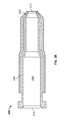
- FIG. 3Bis a half, side cross-sectional view of a fuel injector of the gas turbine combustor assembly shown in FIG. 2 .
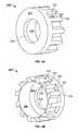
- FIGS. 4A and 4Bare front and rear perspective views of a dome stator of the gas turbine combustor assembly shown in FIG. 2 .
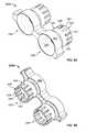
- FIGS. 5A and 5Bare front and rear perspective views of the center dome sleeve of the gas turbine combustor assembly shown in FIG. 2 .
- FIG. 6is a top view of the center dome sleeve of the gas turbine combustor assembly shown in FIG. 2 coupled with corresponding dome stators.
- FIG. 9Ais a perspective view of a can-type gas turbine combustor assembly.
- FIG. 9Bis a half, perspective cross-sectional view of the can-type gas turbine combustor assembly shown in FIG. 9A .
- FIG. 1is a half, side cross-sectional view of an example gas turbine engine 10 .
- the gas turbine engine 10is turbojet-type gas turbine that could be used, for example, to power jet aircrafts.
- turbojet-type gas turbinethat could be used, for example, to power jet aircrafts.
- the concepts described in the present disclosureare not so limited, and can be incorporated in the design of various other types of gas turbine engines (e.g., turbofan, turboprop, turboshaft, or industrial/marine engines).
- the combustor 100includes a combustion shield 102 , multiple fuel injectors 104 , and a combustor dome 106 .
- the high-pressure air 18is mixed with liquid hydrocarbon fuel (not shown) and ignited to produce heated combustion products 22 .
- the combustion products 22are passed through multiple stages of a turbine 24 .
- the turbine 24extracts energy from the high-pressure, high-temperature combustion products 22 .
- Energy extracted from the combustion products 22 by the turbine 24drives the compressor 16 , which is coupled to the turbine by the main shaft 20 .
- Exhaust gas 26 leaving the turbine 24is accelerated into the atmosphere through an exhaust nozzle 28 to provide thrust or propulsion power.
- FIG. 2is a perspective view of an arc segment of an example triple-dome annular gas turbine combustor assembly 200 .
- the arc segmentis part of an uninterrupted ring structure.
- a partial view of the full ring structureis provided here so that individual components can be seen with clarity.
- the combustor assembly 200can, for example, be incorporated in the gas turbine engine 10 .
- FIG. 3Ais a cross-sectional view of the gas turbine combustor assembly 200 taken along the line 3 - 3 in FIG. 2 .
- the combustor assembly 200features a collection of fuel injectors 204 and an annular combustor dome 206 .
- the fuel injectors 204are mounted on fuel injector support structures 208 .
- the fuel injector support structures 208are designed to carry the fuel injectors 204 and to supply the fuel injectors with liquid or gaseous fuel.
- Each of the fuel injector support structures 208caries multiple fuel injectors 204 .
- Liquid or gaseous fuelis routed to the fuel injectors 204 through passages formed on the interior of the fuel injector support structures 208 .
- a fuel delivery system(not shown) is used to supply fuel to the fuel injectors 204 from one or more fuel sources (not shown).
- the fuel delivery systemis a multi-stage fuel injection system designed to supply fuel independently to different groups of fuel injectors 204 .
- the fuel delivery systemcan supply fuel to a first group of fuel injectors 204 at one flow rate and to a second group of fuel injectors at a different (lesser or greater) flow rate.
- the fuel delivery systemcan supply fuel to the first group of fuel injectors 204 , but not supply fuel to the second group of fuel injectors.
- the fuel delivery systemcan be designed to separately control any number of groups of fuel injectors 204 . The complexity of the fuel delivery systems scales with the number of control groups of fuel injectors.
- FIG. 3Bis a half, side cross-sectional view of a fuel injector 204 .
- the fuel injectors 204are external mixing air-blast liquid fuel injectors.
- the fuel injectors 204include a primary air passage 210 terminating in a converging-nozzle outlet 212 .
- the inlet 214 of the primary air passage 210is in fluid communication with the outlet of the compressor 16 , and therefore receives a continuous stream of high-pressure air.
- the primary air passage 210includes a swirler element designed to impart a swirling flow pattern on primary airflow before exiting the outlet 212 .
- the combustor dome 206facilitates the mixing of liquid fuel and air ejecta from the fuel injectors 204 with a secondary swirling airflow.
- the mixinginvolves a shearing interaction between the primary airflow, the annular film of liquid fuel, and the secondary airflow.
- the mixingresults in the atomizing of the liquid fuel into a fine mist of fuel droplets just upstream of a primary combustion zone, where the fuel-air mixture is ignited.
- the secondary swirling airflowdilutes the fuel-air ratio and imparts (or augments) a swirling motion on ejecta from the fuel injectors 204 .
- the swirling motionresults, among other things, in improved flame stabilization and improved mixing.
- the combustor dome 206includes a collection of dome stators 220 , one dome stator installed on each fuel injector 204 , and an annular dome sleeve 222 carried by the collection of dome stators.
- the dome stators 220are fixedly mounted to the fuel injectors 204 carried by the support structures 208 .
- the dome stators 220 and fuel injectors 204are held in a stationary position relative to the dome sleeve 222 .
- the dome sleeve 222includes an inner sleeve 222 a , a center sleeve 222 b , and an outer sleeve 222 c .
- the forward portion of the inlet chamber 240is a conical shaped region presenting a converging inner surface 256 .
- the inner surface 256cooperates with a converging outer surface 258 of the conical shaped outlet of the fuel injector 204 to define a pinch gap 260 between the surfaces.
- the pinch gap 260is positioned upstream of the throat 242 .
- FIG. 6is a top view of the center dome sleeve 222 b coupled with corresponding dome stators 220 .
- the ribs 230 and grooves 232 of the dome stator 220form an interlocking finger joint 263 with the fingers 248 and sockets 250 of the center dome sleeve 222 b . That is, the ribs 230 of the dome stator 220 are received by the sockets 250 of the center dome sleeve 222 b , and the fingers 248 of the center dome sleeve 222 b are received by the grooves 232 of the dome stator 222 .
- the fingers 248 of the center dome sleeve 222 brest on the floor surface 234 of the grooves 232 on the dome stator 220 , and the complementary flank surfaces 251 and 236 of the fingers 248 and ribs 230 are in sliding contact.
- movement of the center dome sleeve 222 b relative to the dome stator 220allowed in the axial direction, but inhibited in all other directions.
- the slanted flank surfaces 251 and 236 of the fingers 248 and ribs 230cause the radial gaps 266 to be angled relative to the tangent planes of the circular side walls of the dome stator 220 and center dome sleeve 222 b .
- the angled radial gaps 266impart a swirling motion on the secondary airflow.
- the open area of the radial gaps 266can be increased or decreased by moving the center dome sleeve 222 b relative to the stationary dome stator 220 .
- Moving the center dome sleeve 222 b away from the dome stator 220increases the axial dimension of the radial gaps 266 and therefore increases the open area of the radial gaps.
- moving the center dome sleeve 222 b towards the dome stator 222decreases the axial dimension of the radial gaps 266 and therefore decreases the open area of the radial gaps.
- Increasing or decreasing the open area of the radial gaps 266adjusts the flow area of the air inlet 268 and thus the flow rate of the secondary airflow. When the radial gaps 266 have more open area, the overall flow area of the air inlet 268 is larger and the flow rate of the secondary airflow is greater, and vice versa.
- axial movement of the center dome sleeve 222 b relative to the stationary fuel injectors 204adjusts the flow area of the pinch gap 260 ; widening the pinch gap when the center dome sleeve is moved away from the fuel injectors, and narrowing the pinch gap when the center dome sleeve is moved towards the fuel injectors.
- the inner dome sleeve 222 a and the outer dome sleeve 222 cfunction identically to the center dome sleeve 222 b .
- Each of the dome sleeves 222 a , 222 b , and 222 ccan be moved independently relative to the stationary dome stators 220 and fuel injectors 204 to locally regulate the fuel-air mixture entering the primary combustion zone.
- the inner dome sleeve 222 aregulates the fuel-air mixture from fuel injectors 204 arranged along the inner diameter of the combustor; the outer dome sleeve 222 c regulates the fuel-air mixture from fuel injectors 204 arranged along the outer diameter of the combustor, and the center dome sleeve 222 b regulates the fuel-air mixture of fuel injectors arranged between the inner dome sleeve 222 a and the outer dome sleeve 222 c .
- the dome sleeves 222 a , 222 b , and 222 ccan be used to achieve a gradient fuel/air ratio in the radial direction of the combustor.
- FIG. 8is a half, perspective cross-sectional view of a dual-dome annular gas turbine combustor assembly 300 .
- the combustor assembly 300is similar to the combustor assembly 200 .
- the combustor assembly 300includes two dome sleeves (as opposed to three), a first dome sleeve 322 a aligned with fuel injectors 304 arranged along the outer diameter of the combustor, and a second dome sleeve 322 b aligned with fuel injectors along the inner diameter of the combustor.
- the first dome sleeve 322 a and the second dome sleeve 322 bhave independent axial motion against the stators 320 .
- each of the nozzle sleeves 322 a and 322 bhas two sets of secondary adjustable airflow openings 269 a , and 269 b separated axially.
- One set of the openingsmay have the flank surfaces that can be flat or curved and slanted in opposite angle to the other set so to forms an air swirling direction opposite to that of the other's.
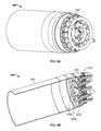
- FIG. 9Ais a perspective view of a can-type gas turbine combustor assembly 400 .
- FIG. 9Bis a half, perspective cross-sectional view of the gas turbine combustor assembly 400 shown in FIG. 9A .
- the combustor assembly 400is similar to the combustor assembly 200 described above.
- the fuel injectors 404 , dome stators 420 , and dome sleeves 422 a , 422 b , and 422 care arranged in a miniature self-contained unit.
- the combustor assembly 400is shielded by a combustion shield 402 .
- the gas turbine engine 10is operated at a low power condition (e.g., a startup or idle condition).
- a low power conditione.g., a startup or idle condition
- the flow rate of liquid fuel provided to the fuel ejectors 204is relatively low.
- the fuel-air ratiowhile constant over the entire combustor 100 , can be made locally rich at particular regions of the combustor.
- the fuel injectors 204 aligned with the outer dome sleeve 222 care rendered temporarily inoperable, such that the entire flow of liquid fuel is delivered to the fuel injectors aligned with the inner dome sleeve 222 a and the center dome sleeve 222 b .
- the flow rate of the secondary airis reduced by moving the inner dome sleeve 222 a and the center dome sleeve 222 b towards the stationary dome stators 220 and fuel injectors 204 .
- the secondary airflow through the outer dome sleeveis proportionately increased by moving the outer dome sleeve 222 c (aligned with the inoperable fuel injectors) away from the dome stators 220 and fuel injectors 204 .
- the gas turbine engine 10is operated at a high power condition.
- the flow rate of liquid fuel provided to the fuel ejectors 204is relatively high.
- a fuel-air ratio gradientis created along the radial direction of the combustor 100 , with the highest fuel-air ratio being near the inner diameter of the combustor and the lowest fuel-air ratio being near the outer diameter of the combustor.
- This configurationprovides that the highest temperature combustion products 22 will be delivered to the outer portion of the turbine blades, and the lowest temperature combustion products will be deviled to the inner portion (or “root”) of the turbine blades.
- This fuel-air ratio gradientis achieved by moving the inner dome sleeve 222 a away from the stationary dome stators 220 and fuel injectors 204 to increase the flow rate of secondary air through the inner dome sleeve, while moving the outer dome sleeve 222 c towards the dome stators and fuel injectors to proportionately decrease the flow of secondary air through the outer dome sleeve.
- the adjustable dome sleeves of the combustor assemblycan be operated to match the different levels of airflow provided by the compressor.
- the dome sleevescan be moved axially forward or rearward in unison to increase or decrease the overall airflow through the combustor to match the compressor.
Landscapes
- Engineering & Computer Science (AREA)
- Chemical & Material Sciences (AREA)
- Combustion & Propulsion (AREA)
- Mechanical Engineering (AREA)
- General Engineering & Computer Science (AREA)
- Structures Of Non-Positive Displacement Pumps (AREA)
Abstract
Description
Claims (22)
Applications Claiming Priority (1)
| Application Number | Priority Date | Filing Date | Title |
|---|---|---|---|
| PCT/US2013/046413WO2014204449A1 (en) | 2013-06-18 | 2013-06-18 | Gas turbine engine flow regulating |
Publications (2)
| Publication Number | Publication Date |
|---|---|
| US20160138807A1 US20160138807A1 (en) | 2016-05-19 |
| US10408454B2true US10408454B2 (en) | 2019-09-10 |
Family
ID=48795894
Family Applications (1)
| Application Number | Title | Priority Date | Filing Date |
|---|---|---|---|
| US14/899,982Active2035-12-21US10408454B2 (en) | 2013-06-18 | 2013-06-18 | Gas turbine engine flow regulating |
Country Status (4)
| Country | Link |
|---|---|
| US (1) | US10408454B2 (en) |
| EP (1) | EP3011231B1 (en) |
| CN (1) | CN105899878B (en) |
| WO (1) | WO2014204449A1 (en) |
Cited By (3)
| Publication number | Priority date | Publication date | Assignee | Title |
|---|---|---|---|---|
| US20210260607A1 (en)* | 2020-02-24 | 2021-08-26 | Altair (UK) Limited | Pulse nozzle for filter cleaning systems |
| US11421601B2 (en) | 2019-03-28 | 2022-08-23 | Woodward, Inc. | Second stage combustion for igniter |
| US12305578B2 (en) | 2020-06-23 | 2025-05-20 | Woodward, Inc. | Ignition system for power generation engine |
Families Citing this family (10)
| Publication number | Priority date | Publication date | Assignee | Title |
|---|---|---|---|---|
| US9644844B2 (en) | 2011-11-03 | 2017-05-09 | Delavan Inc. | Multipoint fuel injection arrangements |
| US9188063B2 (en) | 2011-11-03 | 2015-11-17 | Delavan Inc. | Injectors for multipoint injection |
| US10584639B2 (en) | 2014-08-18 | 2020-03-10 | Woodward, Inc. | Torch igniter |
| US10578021B2 (en)* | 2015-06-26 | 2020-03-03 | Delavan Inc | Combustion systems |
| FR3038363B1 (en)* | 2015-07-03 | 2020-01-10 | Safran Aircraft Engines | ANNULAR COMBUSTION CHAMBER WITH FIXED DIAPHRAGM FOR A GAS TURBINE |
| US10267524B2 (en) | 2015-09-16 | 2019-04-23 | Woodward, Inc. | Prefilming fuel/air mixer |
| DE102017201771A1 (en)* | 2017-02-03 | 2018-08-09 | Siemens Aktiengesellschaft | Circumferential grading concept for a burner assembly |
| US12025311B2 (en)* | 2021-08-24 | 2024-07-02 | Solar Turbines Incorporated | Micromix fuel injection air nozzles |
| KR102760449B1 (en)* | 2022-05-12 | 2025-02-03 | 윤준태 | Seawater Vaporizer For Making Artificial Rain Clouds And System For Treating Harmful Fine Dust And Fallout In The Air Using The same |
| US20250207775A1 (en)* | 2023-12-22 | 2025-06-26 | General Electric Company | Turbine engine having a combustion section with a fuel nozzle |
Citations (63)
| Publication number | Priority date | Publication date | Assignee | Title |
|---|---|---|---|---|
| US3283802A (en) | 1964-06-11 | 1966-11-08 | Fuel Firing Ltd | Multi-stage burner unit |
| US3763650A (en) | 1971-07-26 | 1973-10-09 | Westinghouse Electric Corp | Gas turbine temperature profiling structure |
| US3869246A (en)* | 1973-12-26 | 1975-03-04 | Gen Motors Corp | Variable configuration combustion apparatus |
| US3905192A (en) | 1974-08-29 | 1975-09-16 | United Aircraft Corp | Combustor having staged premixing tubes |
| US4007001A (en)* | 1975-04-14 | 1977-02-08 | Phillips Petroleum Company | Combustors and methods of operating same |
| US4007002A (en)* | 1975-04-14 | 1977-02-08 | Phillips Petroleum Company | Combustors and methods of operating same |
| US4430860A (en)* | 1979-12-19 | 1984-02-14 | The French State | Supercharged internal combustion engines, inter alia diesel engines |
| US4542622A (en)* | 1982-07-22 | 1985-09-24 | United Technologies Corporation | Variable area inlet guide vanes |
| US4677822A (en)* | 1985-02-22 | 1987-07-07 | Hitachi, Ltd. | Gas turbine combustor |
| US4754600A (en)* | 1986-03-20 | 1988-07-05 | Societe Nationale D'etude Et De Construction De Moteurs D'aviation (Snecma) | Axial-centripetal swirler injection apparatus |
| US4903478A (en)* | 1987-06-25 | 1990-02-27 | General Electric Company | Dual manifold fuel system |
| US5197290A (en) | 1990-03-26 | 1993-03-30 | Fuel Systems Textron Inc. | Variable area combustor air swirler |
| JPH05185537A (en) | 1992-01-10 | 1993-07-27 | Tdk Corp | Plate-shaped blank puncher |
| US5333459A (en) | 1992-06-19 | 1994-08-02 | Mtu Motoren- Und Turbinen-Union Muenchen Gmbh | Device for operating a swirler which controls combustion air of a burner for gas turbine engines |
| US5343693A (en) | 1991-09-19 | 1994-09-06 | Hitachi, Ltd. | Combustor and method of operating the same |
| US5373693A (en) | 1992-08-29 | 1994-12-20 | Mtu Motoren- Und Turbinen-Union Munchen Gmbh | Burner for gas turbine engines with axially adjustable swirler |
| US5417054A (en) | 1992-05-19 | 1995-05-23 | Fuel Systems Textron, Inc. | Fuel purging fuel injector |
| US5490378A (en) | 1991-03-30 | 1996-02-13 | Mtu Motoren- Und Turbinen-Union Muenchen Gmbh | Gas turbine combustor |
| US5505045A (en) | 1992-11-09 | 1996-04-09 | Fuel Systems Textron, Inc. | Fuel injector assembly with first and second fuel injectors and inner, outer, and intermediate air discharge chambers |
| US5572862A (en) | 1993-07-07 | 1996-11-12 | Mowill Rolf Jan | Convectively cooled, single stage, fully premixed fuel/air combustor for gas turbine engine modules |
| US5573395A (en) | 1994-04-02 | 1996-11-12 | Abb Management Ag | Premixing burner |
| US5647538A (en) | 1993-12-23 | 1997-07-15 | Rolls Royce Plc | Gas turbine engine fuel injection apparatus |
| US5664412A (en) | 1995-03-25 | 1997-09-09 | Rolls-Royce Plc | Variable geometry air-fuel injector |
| US5749219A (en) | 1989-11-30 | 1998-05-12 | United Technologies Corporation | Combustor with first and second zones |
| US5836163A (en) | 1996-11-13 | 1998-11-17 | Solar Turbines Incorporated | Liquid pilot fuel injection method and apparatus for a gas turbine engine dual fuel injector |
| US5836164A (en) | 1995-01-30 | 1998-11-17 | Hitachi, Ltd. | Gas turbine combustor |
| US5930999A (en) | 1997-07-23 | 1999-08-03 | General Electric Company | Fuel injector and multi-swirler carburetor assembly |
| US5996333A (en)* | 1996-10-16 | 1999-12-07 | Societe National D'etude Et De Construction De Moteurs D'aviation | Oxidizer control device for a gas turbine engine |
| US6089170A (en) | 1997-12-18 | 2000-07-18 | Electric Power Research Institute, Inc. | Apparatus and method for low-NOx gas combustion |
| US6199367B1 (en) | 1996-04-26 | 2001-03-13 | General Electric Company | Air modulated carburetor with axially moveable fuel injector tip and swirler assembly responsive to fuel pressure |
| US6442940B1 (en)* | 2001-04-27 | 2002-09-03 | General Electric Company | Gas-turbine air-swirler attached to dome and combustor in single brazing operation |
| US6530223B1 (en) | 1998-10-09 | 2003-03-11 | General Electric Company | Multi-stage radial axial gas turbine engine combustor |
| US6623267B1 (en) | 2002-12-31 | 2003-09-23 | Tibbs M. Golladay, Jr. | Industrial burner |
| CN1715745A (en) | 2004-07-01 | 2006-01-04 | 气体产品与化学公司 | Staged combustion system with ignition-assisted fuel lances |
| US20070028620A1 (en) | 2005-07-25 | 2007-02-08 | General Electric Company | Free floating mixer assembly for combustor of a gas turbine engine |
| US20070074452A1 (en) | 2005-09-30 | 2007-04-05 | Continental Controls Corporation | Gaseous fuel and air mixing venturi device and method for carburetor |
| US7200986B2 (en) | 2003-08-16 | 2007-04-10 | Rolls-Royce Plc | Fuel injector |
| CN101069040A (en) | 2004-12-08 | 2007-11-07 | Lpp燃料有限公司 | Method and apparatus for conditioning liquid hydrocarbon fuels |
| US7302801B2 (en) | 2004-04-19 | 2007-12-04 | Hamilton Sundstrand Corporation | Lean-staged pyrospin combustor |
| US20080163627A1 (en) | 2007-01-10 | 2008-07-10 | Ahmed Mostafa Elkady | Fuel-flexible triple-counter-rotating swirler and method of use |
| CN101294714A (en) | 2007-04-26 | 2008-10-29 | 株式会社日立制作所 | Fuel supply method for burner and burner |
| US7500347B2 (en) | 2003-08-16 | 2009-03-10 | Rolls-Royce Plc | Variable geometry combustor |
| US20100051724A1 (en) | 2008-08-27 | 2010-03-04 | Woodward Governor Company | Dual Action Fuel Injection Nozzle |
| US7762073B2 (en) | 2006-03-01 | 2010-07-27 | General Electric Company | Pilot mixer for mixer assembly of a gas turbine engine combustor having a primary fuel injector and a plurality of secondary fuel injection ports |
| US7827795B2 (en) | 2008-09-19 | 2010-11-09 | Woodward Governor Company | Active thermal protection for fuel injectors |
| WO2010128882A1 (en) | 2009-05-07 | 2010-11-11 | General Electric Company | Multi-premixer fuel nozzle |
| US7832377B2 (en) | 2008-09-19 | 2010-11-16 | Woodward Governor Company | Thermal protection for fuel injectors |
| US20110056205A1 (en) | 2008-03-07 | 2011-03-10 | Alstom Technology Ltd | Burner arrangement and use of same |
| US20110061389A1 (en)* | 2009-09-15 | 2011-03-17 | General Electric Company | Radial Inlet Guide Vanes for a Combustor |
| US8001761B2 (en) | 2006-05-23 | 2011-08-23 | General Electric Company | Method and apparatus for actively controlling fuel flow to a mixer assembly of a gas turbine engine combustor |
| EP2415993A2 (en) | 2010-08-05 | 2012-02-08 | Hitachi Ltd. | Fuel control device and fuel control method for advanced humid air turbines |
| EP2458284A2 (en) | 2010-11-24 | 2012-05-30 | Delavan Inc. | Low calorific value fuel combustion systems for gas turbine engines |
| US8205643B2 (en) | 2008-10-16 | 2012-06-26 | Woodward, Inc. | Multi-tubular fluid transfer conduit |
| US8234873B2 (en) | 2008-08-28 | 2012-08-07 | Woodward, Inc. | Multi passage fuel manifold and methods of construction |
| US20120234013A1 (en) | 2011-03-18 | 2012-09-20 | Delavan Inc | Recirculating product injection nozzle |
| EP2557362A2 (en) | 2011-08-08 | 2013-02-13 | General Electric Company | Turbomachine combustor assembly |
| US20130036741A1 (en) | 2010-11-24 | 2013-02-14 | Delavan Inc | Multipoint injectors with auxiliary stage |
| US20130174571A1 (en) | 2012-01-06 | 2013-07-11 | Hitachi, Ltd. | Fuel Flow Control Method and Fuel Flow Control System of Gas Turbine Combustor for Humid Air Gas Turbine |
| EP2626635A2 (en) | 2012-02-07 | 2013-08-14 | General Electric Company | Combustor assembly with trapped vortex cavity |
| US8522555B2 (en) | 2009-05-20 | 2013-09-03 | General Electric Company | Multi-premixer fuel nozzle support system |
| US20150128607A1 (en) | 2013-11-11 | 2015-05-14 | Woodward, Inc. | Multi-Swirler Fuel/Air Mixer with Centralized Fuel Injection |
| US20150211742A1 (en) | 2014-01-29 | 2015-07-30 | Woodward, Inc. | Combustor with Staged, Axially Offset Combustion |
| US9188341B2 (en) | 2008-04-11 | 2015-11-17 | General Electric Company | Fuel nozzle |
Family Cites Families (2)
| Publication number | Priority date | Publication date | Assignee | Title |
|---|---|---|---|---|
| JP2930450B2 (en)* | 1991-07-10 | 1999-08-03 | 三菱重工業株式会社 | Premixed combustor |
| US8327296B2 (en)* | 2010-04-16 | 2012-12-04 | Google Inc. | Extended keyboard user interface |
- 2013
- 2013-06-18CNCN201380078939.3Apatent/CN105899878B/enactiveActive
- 2013-06-18EPEP13737901.2Apatent/EP3011231B1/enactiveActive
- 2013-06-18WOPCT/US2013/046413patent/WO2014204449A1/enactiveApplication Filing
- 2013-06-18USUS14/899,982patent/US10408454B2/enactiveActive
Patent Citations (67)
| Publication number | Priority date | Publication date | Assignee | Title |
|---|---|---|---|---|
| US3283802A (en) | 1964-06-11 | 1966-11-08 | Fuel Firing Ltd | Multi-stage burner unit |
| US3763650A (en) | 1971-07-26 | 1973-10-09 | Westinghouse Electric Corp | Gas turbine temperature profiling structure |
| US3869246A (en)* | 1973-12-26 | 1975-03-04 | Gen Motors Corp | Variable configuration combustion apparatus |
| US3905192A (en) | 1974-08-29 | 1975-09-16 | United Aircraft Corp | Combustor having staged premixing tubes |
| US4007001A (en)* | 1975-04-14 | 1977-02-08 | Phillips Petroleum Company | Combustors and methods of operating same |
| US4007002A (en)* | 1975-04-14 | 1977-02-08 | Phillips Petroleum Company | Combustors and methods of operating same |
| US4430860A (en)* | 1979-12-19 | 1984-02-14 | The French State | Supercharged internal combustion engines, inter alia diesel engines |
| US4542622A (en)* | 1982-07-22 | 1985-09-24 | United Technologies Corporation | Variable area inlet guide vanes |
| US4677822A (en)* | 1985-02-22 | 1987-07-07 | Hitachi, Ltd. | Gas turbine combustor |
| US4754600A (en)* | 1986-03-20 | 1988-07-05 | Societe Nationale D'etude Et De Construction De Moteurs D'aviation (Snecma) | Axial-centripetal swirler injection apparatus |
| US4903478A (en)* | 1987-06-25 | 1990-02-27 | General Electric Company | Dual manifold fuel system |
| US5749219A (en) | 1989-11-30 | 1998-05-12 | United Technologies Corporation | Combustor with first and second zones |
| US5197290A (en) | 1990-03-26 | 1993-03-30 | Fuel Systems Textron Inc. | Variable area combustor air swirler |
| US5490378A (en) | 1991-03-30 | 1996-02-13 | Mtu Motoren- Und Turbinen-Union Muenchen Gmbh | Gas turbine combustor |
| US5343693A (en) | 1991-09-19 | 1994-09-06 | Hitachi, Ltd. | Combustor and method of operating the same |
| JPH05185537A (en) | 1992-01-10 | 1993-07-27 | Tdk Corp | Plate-shaped blank puncher |
| US5417054A (en) | 1992-05-19 | 1995-05-23 | Fuel Systems Textron, Inc. | Fuel purging fuel injector |
| US5333459A (en) | 1992-06-19 | 1994-08-02 | Mtu Motoren- Und Turbinen-Union Muenchen Gmbh | Device for operating a swirler which controls combustion air of a burner for gas turbine engines |
| US5373693A (en) | 1992-08-29 | 1994-12-20 | Mtu Motoren- Und Turbinen-Union Munchen Gmbh | Burner for gas turbine engines with axially adjustable swirler |
| US5505045A (en) | 1992-11-09 | 1996-04-09 | Fuel Systems Textron, Inc. | Fuel injector assembly with first and second fuel injectors and inner, outer, and intermediate air discharge chambers |
| US5572862A (en) | 1993-07-07 | 1996-11-12 | Mowill Rolf Jan | Convectively cooled, single stage, fully premixed fuel/air combustor for gas turbine engine modules |
| US5647538A (en) | 1993-12-23 | 1997-07-15 | Rolls Royce Plc | Gas turbine engine fuel injection apparatus |
| US5573395A (en) | 1994-04-02 | 1996-11-12 | Abb Management Ag | Premixing burner |
| US5836164A (en) | 1995-01-30 | 1998-11-17 | Hitachi, Ltd. | Gas turbine combustor |
| US5664412A (en) | 1995-03-25 | 1997-09-09 | Rolls-Royce Plc | Variable geometry air-fuel injector |
| US6199367B1 (en) | 1996-04-26 | 2001-03-13 | General Electric Company | Air modulated carburetor with axially moveable fuel injector tip and swirler assembly responsive to fuel pressure |
| US5996333A (en)* | 1996-10-16 | 1999-12-07 | Societe National D'etude Et De Construction De Moteurs D'aviation | Oxidizer control device for a gas turbine engine |
| US5836163A (en) | 1996-11-13 | 1998-11-17 | Solar Turbines Incorporated | Liquid pilot fuel injection method and apparatus for a gas turbine engine dual fuel injector |
| US5930999A (en) | 1997-07-23 | 1999-08-03 | General Electric Company | Fuel injector and multi-swirler carburetor assembly |
| US6089170A (en) | 1997-12-18 | 2000-07-18 | Electric Power Research Institute, Inc. | Apparatus and method for low-NOx gas combustion |
| US6530223B1 (en) | 1998-10-09 | 2003-03-11 | General Electric Company | Multi-stage radial axial gas turbine engine combustor |
| US6442940B1 (en)* | 2001-04-27 | 2002-09-03 | General Electric Company | Gas-turbine air-swirler attached to dome and combustor in single brazing operation |
| US6623267B1 (en) | 2002-12-31 | 2003-09-23 | Tibbs M. Golladay, Jr. | Industrial burner |
| US7500347B2 (en) | 2003-08-16 | 2009-03-10 | Rolls-Royce Plc | Variable geometry combustor |
| US7200986B2 (en) | 2003-08-16 | 2007-04-10 | Rolls-Royce Plc | Fuel injector |
| US7302801B2 (en) | 2004-04-19 | 2007-12-04 | Hamilton Sundstrand Corporation | Lean-staged pyrospin combustor |
| CN1715745A (en) | 2004-07-01 | 2006-01-04 | 气体产品与化学公司 | Staged combustion system with ignition-assisted fuel lances |
| CN101069040A (en) | 2004-12-08 | 2007-11-07 | Lpp燃料有限公司 | Method and apparatus for conditioning liquid hydrocarbon fuels |
| US20070028620A1 (en) | 2005-07-25 | 2007-02-08 | General Electric Company | Free floating mixer assembly for combustor of a gas turbine engine |
| US7415826B2 (en) | 2005-07-25 | 2008-08-26 | General Electric Company | Free floating mixer assembly for combustor of a gas turbine engine |
| US20070074452A1 (en) | 2005-09-30 | 2007-04-05 | Continental Controls Corporation | Gaseous fuel and air mixing venturi device and method for carburetor |
| US7762073B2 (en) | 2006-03-01 | 2010-07-27 | General Electric Company | Pilot mixer for mixer assembly of a gas turbine engine combustor having a primary fuel injector and a plurality of secondary fuel injection ports |
| US8001761B2 (en) | 2006-05-23 | 2011-08-23 | General Electric Company | Method and apparatus for actively controlling fuel flow to a mixer assembly of a gas turbine engine combustor |
| US20080163627A1 (en) | 2007-01-10 | 2008-07-10 | Ahmed Mostafa Elkady | Fuel-flexible triple-counter-rotating swirler and method of use |
| US20090031728A1 (en) | 2007-04-26 | 2009-02-05 | Keisuke Miura | Combustor and a fuel supply method for the combustor |
| CN101294714A (en) | 2007-04-26 | 2008-10-29 | 株式会社日立制作所 | Fuel supply method for burner and burner |
| US20110056205A1 (en) | 2008-03-07 | 2011-03-10 | Alstom Technology Ltd | Burner arrangement and use of same |
| US9188341B2 (en) | 2008-04-11 | 2015-11-17 | General Electric Company | Fuel nozzle |
| US20100051724A1 (en) | 2008-08-27 | 2010-03-04 | Woodward Governor Company | Dual Action Fuel Injection Nozzle |
| US8234873B2 (en) | 2008-08-28 | 2012-08-07 | Woodward, Inc. | Multi passage fuel manifold and methods of construction |
| US7832377B2 (en) | 2008-09-19 | 2010-11-16 | Woodward Governor Company | Thermal protection for fuel injectors |
| US7827795B2 (en) | 2008-09-19 | 2010-11-09 | Woodward Governor Company | Active thermal protection for fuel injectors |
| US8205643B2 (en) | 2008-10-16 | 2012-06-26 | Woodward, Inc. | Multi-tubular fluid transfer conduit |
| US20120031097A1 (en) | 2009-05-07 | 2012-02-09 | General Electric Company | Multi-premixer fuel nozzle |
| WO2010128882A1 (en) | 2009-05-07 | 2010-11-11 | General Electric Company | Multi-premixer fuel nozzle |
| US8522555B2 (en) | 2009-05-20 | 2013-09-03 | General Electric Company | Multi-premixer fuel nozzle support system |
| US20110061389A1 (en)* | 2009-09-15 | 2011-03-17 | General Electric Company | Radial Inlet Guide Vanes for a Combustor |
| EP2415993A2 (en) | 2010-08-05 | 2012-02-08 | Hitachi Ltd. | Fuel control device and fuel control method for advanced humid air turbines |
| EP2458284A2 (en) | 2010-11-24 | 2012-05-30 | Delavan Inc. | Low calorific value fuel combustion systems for gas turbine engines |
| US20130036741A1 (en) | 2010-11-24 | 2013-02-14 | Delavan Inc | Multipoint injectors with auxiliary stage |
| US20120234013A1 (en) | 2011-03-18 | 2012-09-20 | Delavan Inc | Recirculating product injection nozzle |
| CN102927592A (en) | 2011-08-08 | 2013-02-13 | 通用电气公司 | Turbomachine combustor assembly |
| EP2557362A2 (en) | 2011-08-08 | 2013-02-13 | General Electric Company | Turbomachine combustor assembly |
| US20130174571A1 (en) | 2012-01-06 | 2013-07-11 | Hitachi, Ltd. | Fuel Flow Control Method and Fuel Flow Control System of Gas Turbine Combustor for Humid Air Gas Turbine |
| EP2626635A2 (en) | 2012-02-07 | 2013-08-14 | General Electric Company | Combustor assembly with trapped vortex cavity |
| US20150128607A1 (en) | 2013-11-11 | 2015-05-14 | Woodward, Inc. | Multi-Swirler Fuel/Air Mixer with Centralized Fuel Injection |
| US20150211742A1 (en) | 2014-01-29 | 2015-07-30 | Woodward, Inc. | Combustor with Staged, Axially Offset Combustion |
Non-Patent Citations (6)
| Title |
|---|
| Authorized Officer Reni De Meester, PCT International Search Report and Written Opinion, PCT/US2013/046413, dated Apr. 4, 2014, 14 pages. |
| Communication Pursuant to Article 94(3) EPC, European Application No. 13737901.2, dated Jun. 20, 2017, 4 pages. |
| International Preliminary Report on Patentability issued in International Application No. PCT/US2013/046413 dated Oct. 28, 2015; 9 pages. |
| Office Action issued in Chinese Application No. 201380078939.3 dated Feb. 12, 2018; 8 pages with English Translation. |
| Office Action issued in Chinese Application No. 201380078939.3 dated Jul. 4, 2017; 17 pages. |
| Written Opinion of the International Preliminary Examining Authority issued in International Application No. PCT/US2013/046413 dated Jul. 14, 2015; 8 pages. |
Cited By (5)
| Publication number | Priority date | Publication date | Assignee | Title |
|---|---|---|---|---|
| US11421601B2 (en) | 2019-03-28 | 2022-08-23 | Woodward, Inc. | Second stage combustion for igniter |
| US11965466B2 (en) | 2019-03-28 | 2024-04-23 | Woodward, Inc. | Second stage combustion for igniter |
| US20210260607A1 (en)* | 2020-02-24 | 2021-08-26 | Altair (UK) Limited | Pulse nozzle for filter cleaning systems |
| US11872576B2 (en)* | 2020-02-24 | 2024-01-16 | Altair (UK) Limited | Pulse nozzle for filter cleaning systems |
| US12305578B2 (en) | 2020-06-23 | 2025-05-20 | Woodward, Inc. | Ignition system for power generation engine |
Also Published As
| Publication number | Publication date |
|---|---|
| US20160138807A1 (en) | 2016-05-19 |
| EP3011231A1 (en) | 2016-04-27 |
| WO2014204449A1 (en) | 2014-12-24 |
| CN105899878A (en) | 2016-08-24 |
| EP3011231B1 (en) | 2019-10-30 |
| CN105899878B (en) | 2018-11-13 |
Similar Documents
| Publication | Publication Date | Title |
|---|---|---|
| US10408454B2 (en) | Gas turbine engine flow regulating | |
| US9562690B2 (en) | Swirler, fuel and air assembly and combustor | |
| US10415832B2 (en) | Multi-swirler fuel/air mixer with centralized fuel injection | |
| US7266945B2 (en) | Fuel injection apparatus | |
| EP3537048B1 (en) | A lean burn fuel injector | |
| US10208956B2 (en) | Combustor for gas turbine engine | |
| US9874148B2 (en) | Hybrid slinger combustion system | |
| EP2743587B1 (en) | A fuel injector | |
| US10883719B2 (en) | Prefilming fuel/air mixer | |
| EP2481985B1 (en) | Fuel injector assembly | |
| US20100212325A1 (en) | Combustion system | |
| US10161634B2 (en) | Airblast fuel injector | |
| CN104373961A (en) | Burner arrangement and method for operating a burner arrangement | |
| US20160061452A1 (en) | Corrugated cyclone mixer assembly to facilitate reduced nox emissions and improve operability in a combustor system | |
| US9958161B2 (en) | Combustor for gas turbine engine | |
| US20170284678A1 (en) | Turbine engine fuel injection system and methods of assembling the same | |
| US10724741B2 (en) | Combustors and methods of assembling the same | |
| US20180195727A1 (en) | Fuel injector |
Legal Events
| Date | Code | Title | Description |
|---|---|---|---|
| AS | Assignment | Owner name:CTSI ASSOCIATES, LLC, INDIANA Free format text:ASSIGNMENT OF ASSIGNORS INTEREST;ASSIGNOR:MONGIA, HUKAM CHAND;REEL/FRAME:039779/0148 Effective date:20130618 Owner name:WOODWARD, INC., COLORADO Free format text:ASSIGNMENT OF ASSIGNORS INTEREST;ASSIGNOR:WOODWARD FST, INC.;REEL/FRAME:039779/0304 Effective date:20130813 Owner name:UNITED STATES GOVERNMENT, OHIO Free format text:ASSIGNMENT OF ASSIGNORS INTEREST;ASSIGNORS:TACINA, KATHLEEN M.;LEE, CHI-MING;BULZAN, DANIEL L.;SIGNING DATES FROM 20130611 TO 20130613;REEL/FRAME:039779/0034 Owner name:WOODWARD, INC., COLORADO Free format text:ASSIGNMENT OF ASSIGNORS INTEREST;ASSIGNOR:LEE, FEI PHILIP;REEL/FRAME:039779/0100 Effective date:20130618 Owner name:WOODWARD FST, INC., MICHIGAN Free format text:ASSIGNMENT OF ASSIGNORS INTEREST;ASSIGNOR:CSTI ASSOCIATES, LLC;REEL/FRAME:040070/0024 Effective date:20130618 Owner name:WOODWARD, INC., COLORADO Free format text:INSTRUMENT OF WAIVER;ASSIGNOR:UNITED STATES GOVERNMENT;REEL/FRAME:040070/0053 Effective date:20150629 | |
| AS | Assignment | Owner name:CSTI ASSOCIATES, LLC, INDIANA Free format text:CORRECTIVE ASSIGNMENT TO CORRECT THE ASSIGNEE NAME PREVIOUSLY RECORDED ON REEL 039779 FRAME 0148. ASSIGNOR(S) HEREBY CONFIRMS THE ASSIGNMENT;ASSIGNOR:MONGIA, HUKAM CHAND;REEL/FRAME:040179/0766 Effective date:20130618 | |
| STPP | Information on status: patent application and granting procedure in general | Free format text:NON FINAL ACTION MAILED | |
| STPP | Information on status: patent application and granting procedure in general | Free format text:NOTICE OF ALLOWANCE MAILED -- APPLICATION RECEIVED IN OFFICE OF PUBLICATIONS | |
| STPP | Information on status: patent application and granting procedure in general | Free format text:PUBLICATIONS -- ISSUE FEE PAYMENT RECEIVED | |
| STPP | Information on status: patent application and granting procedure in general | Free format text:PUBLICATIONS -- ISSUE FEE PAYMENT VERIFIED | |
| STCF | Information on status: patent grant | Free format text:PATENTED CASE | |
| MAFP | Maintenance fee payment | Free format text:PAYMENT OF MAINTENANCE FEE, 4TH YEAR, LARGE ENTITY (ORIGINAL EVENT CODE: M1551); ENTITY STATUS OF PATENT OWNER: LARGE ENTITY Year of fee payment:4 |