US10408000B2 - Rotating control device, and installation and retrieval thereof - Google Patents
Rotating control device, and installation and retrieval thereofDownload PDFInfo
- Publication number
- US10408000B2 US10408000B2US15/153,356US201615153356AUS10408000B2US 10408000 B2US10408000 B2US 10408000B2US 201615153356 AUS201615153356 AUS 201615153356AUS 10408000 B2US10408000 B2US 10408000B2
- Authority
- US
- United States
- Prior art keywords
- control device
- rotating control
- inner mandrel
- lock ring
- running tool
- Prior art date
- Legal status (The legal status is an assumption and is not a legal conclusion. Google has not performed a legal analysis and makes no representation as to the accuracy of the status listed.)
- Active, expires
Links
- 238000009434installationMethods0.000titledescription8
- 238000006073displacement reactionMethods0.000claimsabstractdescription27
- 239000012530fluidSubstances0.000claimsabstractdescription12
- 238000004891communicationMethods0.000claimsabstractdescription8
- 238000000034methodMethods0.000abstractdescription14
- 230000007246mechanismEffects0.000description21
- 230000004044responseEffects0.000description6
- 238000005553drillingMethods0.000description5
- 238000010008shearingMethods0.000description5
- 238000002360preparation methodMethods0.000description3
- 230000006835compressionEffects0.000description2
- 238000007906compressionMethods0.000description2
- 230000002028prematureEffects0.000description2
- 230000000717retained effectEffects0.000description2
- 238000007789sealingMethods0.000description2
- 238000006467substitution reactionMethods0.000description2
- 230000009471actionEffects0.000description1
- 238000007792additionMethods0.000description1
- 230000008859changeEffects0.000description1
- 230000000295complement effectEffects0.000description1
- 238000012217deletionMethods0.000description1
- 230000037430deletionEffects0.000description1
- 230000007257malfunctionEffects0.000description1
- 238000012986modificationMethods0.000description1
- 230000004048modificationEffects0.000description1
- 239000002245particleSubstances0.000description1
- 238000012360testing methodMethods0.000description1
- XLYOFNOQVPJJNP-UHFFFAOYSA-NwaterSubstancesOXLYOFNOQVPJJNP-UHFFFAOYSA-N0.000description1
Images


Classifications
- E—FIXED CONSTRUCTIONS
- E21—EARTH OR ROCK DRILLING; MINING
- E21B—EARTH OR ROCK DRILLING; OBTAINING OIL, GAS, WATER, SOLUBLE OR MELTABLE MATERIALS OR A SLURRY OF MINERALS FROM WELLS
- E21B17/00—Drilling rods or pipes; Flexible drill strings; Kellies; Drill collars; Sucker rods; Cables; Casings; Tubings
- E21B17/01—Risers
- E—FIXED CONSTRUCTIONS
- E21—EARTH OR ROCK DRILLING; MINING
- E21B—EARTH OR ROCK DRILLING; OBTAINING OIL, GAS, WATER, SOLUBLE OR MELTABLE MATERIALS OR A SLURRY OF MINERALS FROM WELLS
- E21B19/00—Handling rods, casings, tubes or the like outside the borehole, e.g. in the derrick; Apparatus for feeding the rods or cables
- E21B19/002—Handling rods, casings, tubes or the like outside the borehole, e.g. in the derrick; Apparatus for feeding the rods or cables specially adapted for underwater drilling
- E—FIXED CONSTRUCTIONS
- E21—EARTH OR ROCK DRILLING; MINING
- E21B—EARTH OR ROCK DRILLING; OBTAINING OIL, GAS, WATER, SOLUBLE OR MELTABLE MATERIALS OR A SLURRY OF MINERALS FROM WELLS
- E21B33/00—Sealing or packing boreholes or wells
- E21B33/02—Surface sealing or packing
- E21B33/08—Wipers; Oil savers
- E21B33/085—Rotatable packing means, e.g. rotating blow-out preventers
Definitions
- This disclosurerelates generally to equipment utilized and operations performed in conjunction with a subterranean well and, in an example described below, more particularly provides a rotating control device, and tools for installation and retrieval of the rotating control device.
- a rotating control deviceis typically used to seal off an annular space between an outer tubular structure (such as, a riser, a housing on a subsea structure in a riser-less system, or a housing attached to a surface wellhead) and an inner tubular (such as, a drill string). At times it may be desired for components (such as, bearings, seals, etc.) of the rotating control device to be retrieved from, or installed in, a riser housing.
- an outer tubular structuresuch as, a riser, a housing on a subsea structure in a riser-less system, or a housing attached to a surface wellhead
- an inner tubularsuch as, a drill string
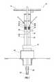
- FIG. 1is a representative partially cross-sectional view of an example of a well system and associated method which can embody principles of this disclosure.
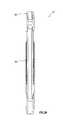
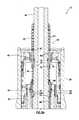
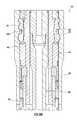
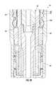
- FIGS. 2A-Eare representative successive axial sections of a portion of the well system depicting a rotating control device being conveyed into a riser housing by a running tool.
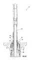
- FIGS. 3A &Bare further enlarged representative cross-sectional views of a latch assembly for the rotating control device operatively located in the riser housing.
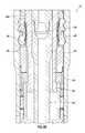
- FIGS. 4A &Bare representative cross-sectional views of the running tool rotated in preparation for release from the latch assembly of the rotating control device.
- FIGS. 5A &Bare representative cross-sectional views of the running tool released from the rotating control device.
- FIGS. 6A &Bare representative cross-sectional views of the running tool longitudinally displaced relative to the rotating control device.
- FIGS. 7A &Bare representative cross-sectional views of a retrieval tool engaged with the latch assembly of the rotating control device.
- FIGS. 8A &Bare representative cross-sectional views of the latch assembly of the rotating control device disengaged from the riser housing by the retrieval tool.
- FIGS. 9A &Bare representative cross-sectional views of a contingency release of the retrieval tool from the latch assembly of the rotating control device.
- FIGS. 10A &Bare representative cross-sectional views of another example of the rotating control device including an equalization valve in respective open and closed configurations.
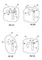
- FIGS. 11A-Dare enlarged representative side views of operational configurations of a release control device of the running tool.
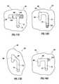
- FIGS. 12A-Dare representative side views of operational configurations of another example of the release control device.
- FIGS. 13A-Dare representative side views of operational configurations of another example of the release control device.
- FIGS. 14A-Dare representative side views of operational configurations of another example of the release control device.
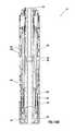
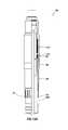
- FIG. 15is a representative partially cross-sectional view of another example of the running tool.
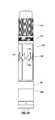
- FIG. 16is a representative side view of interior components of the running tool of FIG. 15 .
- FIG. 17is a representative partially cross-sectional exploded view of some of the interior components of the running tool.
- FIGS. 18A &Bare representative partially cross-sectional views of the running tool engaged with another example of the rotating control device.
- FIG. 1Representatively illustrated in FIG. 1 is a well system 10 and associated method which can embody principles of this disclosure.
- system 10 and methodare merely one example of an application of the principles of this disclosure in practice, and a wide variety of other examples are possible. Therefore, the scope of this disclosure is not limited at all to the details of the system 10 and method described herein and/or depicted in the drawings.
- a generally tubular riser string 12extends between a water-based rig 14 and a lower marine riser package 16 above a subsea wellhead installation 18 (including, for example, various blowout preventers, hangers, fluid connections, etc.).
- a subsea wellhead installation 18including, for example, various blowout preventers, hangers, fluid connections, etc.
- the principles of this disclosurecould be practiced with a land-based rig, or with a riser-less installation.
- a tubular string 20(such as, a jointed or continuous drill string, a coiled tubing string, etc.) extends through the riser string 12 and is used to drill a wellbore 22 into the earth.
- a drill bit 24is connected at a lower end of the tubular string 20 .
- the drill bit 24may be rotated by rotating the tubular string 20 (for example, using a top drive or rotary table of the rig 14 ), and/or a drilling motor may be connected in the tubular string above the drill bit 24 .
- the riser string 12 depicted in FIG. 1includes a riser housing 26 connected in the riser string below a tensioner ring 28 .
- the riser housing 26could be connected above the tensioner ring 28 , or could be otherwise positioned (such as, in the wellhead installation 18 in a riser-less configuration).
- the scope of this disclosureis not limited to any particular details of the riser string 12 or riser housing 26 as described herein or depicted in the drawings.
- the riser housing 26includes a side port 30 that provides for fluid communication between a conduit 32 and an annulus 34 formed radially between the riser string 12 and the tubular string 20 .
- drilling fluidcan be circulated from the rig 14 downward through the tubular string 20 , outward from the drill bit 24 , upward through the annulus 34 , and return to the rig via the conduit 32 .
- a rotating control device 40is installed in the riser housing 26 .
- the rotating control device 40includes one or more annular seals 42 that seal off the annulus 34 above the side port 30 .
- annular seals 42are configured to sealingly engage an exterior of the tubular string 20 .
- the annular seals 42may be of a type known to those skilled in the art as “passive,” “active” or a combination of passive and active. The scope of this disclosure is not limited to use of any particular type of annular seal.
- Rotation of the annular seals 42 relative to the riser housing 26is provided for by a bearing assembly 44 of the rotating control device 40 .
- the annular seals 42 and bearing assembly 44are releasably secured in the riser housing 26 by a latch assembly 46 of the rotating control device.
- the latch assembly 46permits the annular seals 42 and/or the bearing assembly 44 to be installed in, or retrieved from, the riser housing 26 when desired, for example, to service or replace the seals and/or bearing assembly.
- the tubular string 20can include running and retrieval tools, examples of which are described more fully below and depicted in FIGS. 2A-14D , for installing and retrieving the rotating control device 40 .
- running and retrieval toolsexamples of which are described more fully below and depicted in FIGS. 2A-14D , for installing and retrieving the rotating control device 40 .
- FIGS. 2A-14Dfor installing and retrieving the rotating control device 40 .
- the scope of this disclosureis not limited to these particular examples of running and retrieval tools, and is not limited to use of a running or retrieval tool as part of the tubular string 20 of FIG. 1 .
- running tool 50prior to running the rotating control device 40 into the well, running tool 50 must be securely attached to latch assembly 46 of the rotating control device 40 .
- Pins 70are first removed from running tool 50 .
- Running tool 50is then lowered into latch assembly 46 of rotating control device 40 .
- Releasing members 74 of running tool 50are first contacted at upper shoulder 45 of latch assembly 46 of rotating control device 40 .
- Inner mandrel 48 of running tool 50compresses against a biasing device 78 (such as, a compression spring, an elastomeric member, a compressible fluid, etc.) as it is lowered into latch assembly 46 of the rotating control device 40 .
- a biasing device 78such as, a compression spring, an elastomeric member, a compressible fluid, etc.
- the shoulder of inner mandrel 48 that supports releasing members 74 outwardlyis moved below releasing members 74 allowing them to collapse inwardly onto inner mandrel 48 of running tool 50 .
- the biasing device 78urges sleeve 86 (where release members 74 are contained) downwardly and seeks to push the release members 74 back onto the larger shoulder from which they were previously located. Once the proper profile within latch mandrel 62 of latch assembly 46 is located, the biasing device 78 causes release members 74 to move up the shoulder of inner mandrel 48 and engage the profile in latch mandrel 62 of latch assembly 46 . Pins 70 can now be reinstalled into running tool 50 , securely attaching it to the rotating control device 40 .
- the pins 70are used to allow setting of the rotating control device 40 and also enable the release of the running tool 50 from the latch assembly 46 by a rotational release method. Further, pins 70 can be sheared in an emergency situation in the unlikely event of a malfunction in the setting procedure of the rotating control device 40 .
- the various positions of the pins 70 to achieve these functionsare depicted in FIGS. 11A-14D . Once these pins 70 have been secured, the rotating control device 40 cannot be set until the latch members 56 locate the setting profile 58 within the wellbore (see FIG. 2D ). Further, the running tool 50 cannot be rotationally released from the rotating control device 40 until it is set, since it requires frictional resistance from the packer seal 47 of the latch assembly 46 .
- the running tool 50is connected as part of the tubular string 20 , which in this example also includes a retrieval tool 52 connected above the running tool. In other examples, the running tool 50 may be used without the retrieval tool 52 , and vice versa.
- the running tool 50 and retrieval tool 52 of the FIGS. 2A-E exampleinclude helically extending externally fluted sections 54 (see FIG. 2B ) for preventing effective sealing engagement between the annular seals 42 and the tubular string 20 while the rotating control device 40 is being installed or retrieved.
- the fluted sections 54provide for fluid communication longitudinally across the annular seals 42 to prevent swabbing (e.g., producing undesired pressure fluctuations in the wellbore 22 ), and to otherwise prevent buildup of differential pressure across the annular seals, thus slowing the tool string as it is being deployed or being retrieved from the well.
- differential pressure buildup across the annular seals 42could be prevented by other means, such as by use of internal passages in the running and retrieval tools 50 , 52 , by use of internal passages in the rotating control device 40 , etc.
- the scope of this disclosureis not limited to any particular details of the running and retrieval tools 50 , 52 as depicted in the drawings or as described herein.
- the latch assembly 46 of the rotating control device 40includes multiple latch members 56 .
- the latch members 56are radially outwardly biased, and are configured for complementary engagement with an internal profile 58 formed in the riser housing 26 .
- the latch members 56will eventually become aligned with the internal profile 58 , and will radially outwardly extend into engagement with the profile, thereby preventing further downward displacement of the rotating control device relative to the riser housing 26 .
- FIG. 2Cit may be seen that the running tool 50 is releasably secured to the rotating control device 40 by a release mechanism 60 . Operation of the release mechanism 60 to permit longitudinal displacement of the running tool 50 and the remainder of the tubular string 20 relative to the rotating control device 40 is described more fully below.
- the rotating control device 40has been conveyed sufficiently far into the riser housing 26 for the latch members 56 to cooperatively engage the internal profile 58 . Thus, further downward displacement of the rotating control device 40 relative to the riser housing 26 is prevented.
- the latch assembly 46includes an inner mandrel 62 having a radially enlarged portion 62 a .
- the inner mandrel 62is longitudinally displaceable relative to the latch members 56 only after the latch members have engaged the internal profile 58 .
- the running tool 50is moved downwardly against the release members 74 .
- the release colletdisengages from the outer members of the latch assembly 46 at a preset force to allow displacement of the inner mandrel 62 longitudinally downward relative to the latch members 56 .
- This position of the inner mandrel 62is maintained by a gripping engagement between the inner mandrel 62 and a lock ring 64 of the rotating control device 40 .
- the lock ring 64is a resilient C-shaped ring that is biased radially inward into gripping engagement with an outer gripping surface 68 of inner mandrel 62 .
- the lock ring 64includes an internal gripping surface 66 .
- the gripping surface 66can have appropriately configured teeth formed thereon, or can have relatively high hardness particles embedded therein or otherwise secured thereto.
- the inner mandrel 62also includes an external gripping surface 68 . Similar to the lock ring gripping surface 66 , the inner mandrel gripping surface 68 can have appropriately configured teeth formed thereon, or can otherwise be configured for gripping engagement with the lock ring 64 .
- the gripping surfaces 66 , 68are initially spaced apart from each other (e.g., see FIG. 3A ).
- the gripping surfaces 66 , 68engage each other when the inner mandrel 62 displaces downward relative to the latch members 56 .
- the gripping surfaces 66 , 68may not be initially spaced apart from each other.
- the gripping engagement between the lock ring 64 and the inner mandrel 62prevents the inner mandrel from displacing upward relative to the latch members 56 , in order to prevent subsequent disengagement of the latch members 56 from the internal profile 58 .
- the retrieval tool 52can be used to displace the inner mandrel 62 upward when it is desired to retrieve the rotating control device 40 from the riser housing 26 .
- the inner mandrel 48 of the running tool 50has been rotated relative to the rotating control device 40 (in this example, rotated clockwise as viewed from above). This causes alignment of pins 70 with longitudinally extending slots 72 of the release mechanism 60 in preparation to be disengaged from the rotating control device 40 .
- the packer seal 47To rotate the inner mandrel 48 of the running tool 50 , the packer seal 47 must be set to cause necessary resistance for desired rotation. Parts of the latch assembly 46 (the packer seal 47 , the latch body 57 , the inner mandrel 62 ) and parts of the running tool 50 (the release members 74 , sleeve 86 , pins 70 ) are connected in such a manner as to remain stationary during rotation. This alignment of the pins 70 with the slots 72 will permit subsequent upward displacement of the inner mandrel 48 against release members 74 of the release mechanism 60 .
- the running tool 50has been displaced upward relative to the rotating control device 40 .
- This upward displacement of the running tool 50forces the release members 74 to retract inwardly out of engagement with the rotating control device 40 , so that the running tool 50 is now released from the rotating control device 40 and can be displaced substantially upwardly or downwardly relative to the rotating control device 40 .
- release members 74are able to retract inwardly due to a radially reduced portion 48 a of an inner mandrel 48 of the running tool 50 being positioned adjacent the release members when the inner mandrel 48 is displaced upwardly. Note, also, that such upward displacement of the inner mandrel 48 relative to the release members 74 is permitted, due to the alignment between the pins 70 and the longitudinal slots 72 of the release mechanism 60 .
- a biasing device 76urges a relatively thin sleeve 86 downward and over the retracted release members 74 (to prevent subsequent outward displacement of the release members 74 ).
- a top portion 86 a of sleeve 86contains an outwardly biased device 87 (such as a snap ring, an elastomeric member, etc.) which expands outwardly into a recess of an outer housing 51 of the running tool 50 . This also prevents the release mechanism 60 from becoming reengaged.
- Another biasing device 78urges the pins 70 downward relative to the slots 72 .
- the rotating control device 40is representatively illustrated as fully installed in the riser housing 26 .
- the tubular string 20can now be displaced longitudinally upward and downward through the rotating control device 40 (for example, in drilling or other operations) while the annular seals 42 continue to seal off the annulus 34 between the riser housing 26 and the tubular string 20 as shown in FIG. 2E .
- the tubular string 20can be displaced upwardly through the rotating control device 40 , until the retrieval tool 52 engages the latch mandrel 62 of the rotating control device 40 .
- This configurationis representatively illustrated in FIGS. 7A &B.
- engagement members 80 of the retrieval tool 52 in the form of outwardly biased resilient colletsare engaged with an internal profile 82 formed in the inner mandrel 62 of the latch assembly 46 . Such engagement allows the retrieval tool 52 to be used to upwardly displace the inner mandrel 62 .
- the retrieval tool 52displaces the inner mandrel 62 upwardly against the lock ring 64 and moves the latch release sleeve 75 , causing the latch release pins 73 to be sheared.
- the radially enlarged portion 62 a of the inner mandrel 62no longer outwardly supports the latch members 56 , so that the latch members can now radially retract out of engagement with the internal profile 58 of the riser housing 26 .
- the latch members 56may still be biased outwardly, the configurations of the latch members and the internal profile 58 are such that the latch members will retract inward when the retrieval tool 52 is displaced upward relative to the riser housing 26 .
- the rotating control device 40along with the retrieval tool 52 (and the remainder of the tubular string 20 ) can now be retrieved from the riser housing 26 (and the remainder of the riser string 12 ).
- a contingency release techniqueis representatively illustrated.
- a contingency techniquemay be utilized to permit the retrieval tool 52 to be released from the rotating control device 40 , so that the tubular string 20 can be retrieved from the well.
- FIG. 9Anote that a predetermined upward force is required to shear the release ring 83 , and it is applied to the inner mandrel 84 of the retrieval tool 52 .
- Thisenables the inner mandrel 84 to be displaced upwardly relative to the engagement members 80 (which previously remained engaged with the internal profile 82 ).
- a radially reduced portion 84 a of the inner mandrel 84is now adjacent to the engagement members 80 , thereby allowing the engagement members 80 to retract inwardly out of engagement with the internal profile 82 .
- the retrieval tool 52 and the remainder of the tubular string 20may now be retrieved from the well, leaving the rotating control device 40 installed in the riser housing 26 .
- Other toolssuch as hydraulic jars, spears, etc. may be used to retrieve the rotating control device 40 from the riser housing 26 .
- the rotating control device 40includes an equalization valve 90 that can be used to prevent a pressure differential from existing across the rotating control device 40 when it is retrieved from the riser housing 26 (not shown).
- FIG. 10Athe rotating control device 40 and running tool 50 are depicted in a configuration in which the running tool 50 conveys the rotating control device 40 into the riser housing 26 .
- the latch members 56are not radially outwardly supported by the radially enlarged portion 62 a of the inner mandrel 62 .
- the equalization valve 90 in FIG. 10Ais in an open configuration, thereby permitting fluid communication between an interior and an exterior of the rotating control device 40 . This prevents a buildup of differential pressure across the rotating control device 40 .
- FIG. 10Bthe rotating control device 40 and running tool 50 are depicted in a configuration in which the rotating control device 40 has been secured in the riser housing 26 by engaging the latch members 56 with the internal profile 58 and displacing the inner mandrel 62 downward, so that the latch members 56 are radially outwardly supported by the radially enlarged portion 62 a of the inner mandrel (see FIGS. 4A &B; the riser housing 26 is not depicted in FIG. 10B for clarity).
- the equalization valve 90 in FIG. 10Bis in a closed configuration, thereby preventing fluid communication between the interior and exterior of the rotating control device 40 . This allows the sealing engagement between the annular seals 42 and the tubular string 20 to effectively seal off the annulus 34 (see FIG. 1 ), with a pressure differential across the rotating control device 40 .
- the equalization valve 90includes a closing piston 92 that is upwardly biased by a biasing device 94 .
- the closing piston 92 in this exampleis in the form of a sleeve, but in other examples other types of closing pistons may be used (such as, plugs, flappers, etc.).
- the inner mandrel 62displaces downwardly from its FIG. 10A position to its FIG. 10B position, the inner mandrel 62 contacts the closing piston 92 and displaces it downward against a biasing force exerted by the biasing device 94 .
- the biasing device 94will upwardly displace the closing piston 92 as the inner mandrel 62 displaces upward.
- the equalization valve 90closes when the inner mandrel 62 displaces downward, and the equalization valve opens when the inner mandrel displaces upward.
- the inner mandrel 62 and equalization valve 90are appropriately dimensioned, so that the equalization valve 90 does not close until the inner mandrel 62 has displaced downward a sufficient distance for the radially enlarged portion 62 a to outwardly support the latch members 56 . Furthermore, during retrieval of the rotating control device 40 from the riser housing 26 , the equalization valve 90 opens prior to the latch members 56 being permitted to disengage from the internal profile 58 in the riser housing 26 . This prevents any pressure differential from existing across the rotating control device 40 while the latch members 56 are not maintained in engagement with the internal profile 58 .
- FIGS. 11A-14Doperational sequences are representatively depicted for several different examples of the release mechanism 60 that effectuates the release of the running tool 50 from the rotating control device 40 .
- these configurationsallow for a rotational release method of the running tool 50 from the rotating control device 40 .
- the inner mandrel 48 of running tool 50can displace upward relative to release members 74 and when aligned with reduced portion 48 a of inner mandrel 48 , the release members 74 will disengage from the rotating control device 40 . This action only occurs when the pins 70 are aligned with the longitudinally extending slots 72 (see, e.g., FIGS. 4A & 5A ).
- FIGS. 11A-14Dillustrate different examples for how such an alignment and the corresponding displacement of the inner mandrel 48 may be accomplished to achieve release of the running tool 50 . It should be understood that the scope of this disclosure is not limited to just these examples.
- FIGS. 11A-Dare configured for those same items shown in FIGS. 2A-5B .
- a top view of only one of the pins 70 and slots 72are depicted in FIGS. 11A-14D . They are viewed perpendicular to the surface of the inner mandrel 48 of the running tool 50 .
- the release mechanism 60 of running tool 50 shown in FIG. 11Acorresponds to the running tool 50 being in a run-in configuration supporting the weight of the rotating control device 40 as it is lowered into the well.
- the pin 70 and retainer collet 98are received in a circumferentially extending slot 96 formed on the inner mandrel 48 .
- the circumferentially extending slot 96intersects the longitudinally extending slot 72 in FIG. 11A .
- the pin 70is retained in a position of misalignment with slot 72 to prevent premature release of the rotating control device 40 while running in the well. It is retained by a shear member 100 which is located in the retainer collet 98 and extends into the inner mandrel 48 . The retainer collet 98 partially encircles pin 70 . The shear member 100 initially prevents circumferential displacement of the inner mandrel 48 relative to the trapped pin 70 and retainer collet 98 .
- the release mechanism 60 shown in FIG. 11Bcorresponds to the running tool 50 configuration of FIGS. 3A &B, in which the latch members 56 of the rotating control device 40 have engaged the internal profile 58 in the riser housing 26 .
- the pin 70remains circumferentially spaced apart from the slot 72 , as in the configuration of FIG. 11A .
- This configuration of the running tool 50identifies the position as it first locates in riser housing 26 .
- the rotating control device 40has not yet been secured in the riser housing 26 .
- the release mechanism 60 shown in FIG. 11Ccorresponds to the running tool 50 configuration of FIGS. 4A &B, in which the rotating control device 40 has been secured in the riser housing 26 and the inner mandrel 48 of the running tool 50 has been rotated circumferentially clockwise as viewed from above. As a result of this rotation, the shear member 100 has been properly sheared and the pin 70 and retainer collet 98 have been properly aligned in preparation for release from the rotating control device 40 .
- the pin 70is now aligned with the slot 72 .
- the inner mandrel 48can now displace upward relative to the pin 70 and the release members 74 .
- the nose of the retainer collet 98has engaged a perpendicular groove in slot 96 in which it will not allow the pin 70 to come out of alignment with slot 72 . This is needed in the event of any motion in the drill string or back torque from the shear release member 100 .
- the pin 70will remain in a release position until the inner mandrel 48 is pulled upwardly to release the running tool 50 from the rotating control device 40 .
- the release mechanism 60 shown in FIG. 11Dcorresponds to the running tool 50 configuration of FIGS. 5A &B, in which the inner mandrel 48 of the running tool 50 has been displaced upward, thereby causing the release members 74 to retract inwardly, and thereby enabling the release of the running tool 50 from the rotating control device 40 .
- FIGS. 12A-14Dare somewhat similar to each other, in that they incorporate variations of a slot configuration known to those skilled in the art as a “J-slot.”
- the FIGS. 12A, 13A & 14A configurationscorrespond to the FIGS. 2A-E configuration of the running tool 50 .
- the FIGS. 12B, 13B & 14B configurationscorrespond to the FIGS. 3A &B configuration of the running tool 50 .
- the FIGS. 12C, 13C & 14C configurationscorrespond to the FIGS. 4A &B configuration of the running tool 50 .
- the FIGS. 12D, 13D & 14D configurationscorrespond to the FIGS. 5A &B configuration of the running tool 50 .
- the inner mandrel 48is displaced downward relative to the pin 70 , so that the pin traverses a longitudinally extending slot 88 and is now aligned with the circumferentially extending slot 96 .
- Thisis accomplished in the FIGS. 3A &B configuration of the running tool 50 by applying downward force (e.g., “set down” weight) to the running tool 50 after the latch members 56 have cooperatively engaged the internal profile 58 of the riser housing 26 .
- Slot 88is primarily needed to carry the weight of the rotating control device 40 in the well for the configuration of FIG. 13B . Since the pin 70 is not trapped by a shearing member for FIG. 13B , the pin 70 may allow premature release of the rotating control device 40 while running in the well by becoming aligned with slot 72 . Slot 88 is also used to test the rotating control device 40 for proper engagement by pulling up with the running tool 50 or by setting down weight with the running tool 50 to make sure the rotating control device 40 is securely engaged in the riser housing 26 . This is performed prior to shearing the shear member 100 to release the running tool 50 from the rotating control device 40 .
- the inner mandrel 48can then be rotated as in the FIGS. 4A &B configuration. As shown in FIG. 13B , the inner mandrel 48 would have to set down weight and rotate circumferentially simultaneously. In response to this rotation, the pin 70 will displace circumferentially in the slot 96 , as depicted in FIGS. 12C, 13C & 14C , so that the pin is now aligned with the longitudinal slot 72 . Then, upward displacement of the inner mandrel 48 will result in the pin 70 displacing in the longitudinal slot 72 , thereby allowing the release members 74 to retract. The running tool 50 will then disengage the rotating control device 40 .
- the running tool 50can both convey the rotating control device 40 into the riser housing 26 , and retrieve the rotating control device from the housing.
- the FIGS. 15A-18B running tool 50actuates in response to a downward force (e.g., “set down” weight) applied to the running tool.
- a downward forcee.g., “set down” weight
- the rotating control device 40engages a shoulder or “no-go” when it is conveyed into the riser housing 26 by the running tool 50 , at which point a latch mechanism (not shown) in the housing is actuated to engage an external profile 102 (see FIG. 18B ) on the rotating control device to thereby secure the rotating control device to the housing.
- the downward forceis then applied to the running tool 50 to cause the release mechanism to actuate and release the running tool from the rotating control device 40 .
- Retrieval of the rotating control device 40 from the riser housing 26is essentially an opposite order of the steps described above for installing the rotating control device in the housing.
- the running tool 50is conveyed into the rotating control device 40 , and a downward force is applied to the running tool to cause the release members 74 of the release mechanism 60 to extend outwardly into engagement with an internal profile 104 in the rotating control device (see FIG. 18A ).
- the latch mechanism in the riser housing 26is then actuated to release the rotating control device 40 from the housing.
- the running tool 50can then be used to pull the rotating control device 40 out of the riser housing 26 and retrieve the rotating control device to surface.
- the release members 74are in the form of longitudinally extending resilient collets.
- the release members 74When the release members 74 are radially inwardly supported by the inner mandrel 48 , they can securely engage the internal profile 104 in the rotating control device 40 .
- the inner mandrel 48When the inner mandrel 48 is displaced longitudinally relative to the release members 74 , so that the release members are adjacent the radially reduced portion 48 a of the inner mandrel, the release members can flex inward and disengage from the inner profile 104 (during installation), or flex inward and engage the inner profile (during retrieval).
- the release mechanism 60 in this examplecomprises an indexing mechanism that positions the inner mandrel 48 for supporting or un-supporting the release members 74 that snap into the internal profile 104 in the rotating control device 40 .
- the indexing mechanismis provided with two or more positions that alternately support or un-support the release members 74 .
- the indexing mechanismis similar in many respects to a well-known ball point pen retracting mechanism.
- Internal of the sleeve 86is a set of angular bias keys 106 (see FIG. 17 ) that stab into a set of saw-tooth teeth 108 on an indexing sleeve 110 .
- the indexing sleeve 110is rotated freely about the inner mandrel 48 as it rotates and indexes relative to the angular bias keys 106 .
- the inner mandrel 48also has a set of ratcheting teeth 112 that are continually biased into contact with the saw-tooth teeth 108 on the indexing sleeve 110 by a spring 114 .
- Another spring 116is positioned in an upper part of the inner mandrel 48 to continually bias the inner mandrel downward, so that it supports the release members 74 .
- the spring 116exerts a substantially greater biasing force as compared to the spring 114 .
- a weight or forceis applied to overcome the biasing force exerted by the spring 116 and thereby displace the inner mandrel 48 lower end inward (the inner mandrel is shouldered against the rotating control device, see FIG. 18B ).
- the angular bias keys 106release from the saw-tooth teeth 108 and allow the indexing sleeve 110 to jump into a next circumferential position.
- the relative circumferential positions of the saw-tooth teeth 108 and the indexing sleeve 110determine the longitudinal position of the inner mandrel 48 relative to the release members 74 .
- the ratcheting teeth 112will lock the inner mandrel 48 in either a supporting or non-supporting longitudinal position relative to the release members 74 .
- the release members 74are free to deflect inward and snap into (or out of) the internal profile 104 .
- the internal profile 104is positioned above the bearing assembly 44 .
- a spring 118(see FIG. 18A ) is positioned below a sleeve 120 in which the internal profile 104 is formed, to compensate for displacement of the inner mandrel 48 relative to the rotating control device 40 .
- the rotating control device 40can comprise a latch assembly 46 including: at least one outwardly extendable latch member 56 ; an inner mandrel 62 displaceable in a longitudinal direction relative to the latch member 56 to outwardly extend the latch member 56 ; and a lock ring 64 that permits displacement of the inner mandrel 62 in the longitudinal direction, and prevents displacement of the inner mandrel 62 in an opposite longitudinal direction.
- the lock ring 64may comprise a gripping surface 66 .
- the gripping surface 66can include teeth formed on the lock ring 64 .
- the lock ring 64may be generally C-shaped and/or radially expandable.
- the lock ring gripping surface 66may engage a gripping surface 68 formed on the inner mandrel 62 .
- the lock ring gripping surface 66may be initially spaced apart from the inner mandrel gripping surface 68 .
- the lock ring gripping surface 66may engage the inner mandrel gripping surface 68 only in response to the displacement of the inner mandrel 62 in the longitudinal direction.
- the rotating control device 40may include an equalization valve 90 having an open configuration in which fluid communication is permitted between an exterior and an interior of the rotating control device 40 through the equalization valve 90 .
- the latch assembly 46changes from a latched configuration to an unlatched configuration only when the equalization valve 90 is in the open configuration.
- the rotating control device 40may include a bearing assembly 44 secured to the latch assembly 46 .
- the rotating control device 40may also include at least one inwardly extending annular seal 42 rotatably supported by the bearing assembly 44 .
- the rotating control device 40can comprise a latch assembly 46 having a latched configuration and an unlatched configuration, and an equalization valve 90 having an open configuration in which fluid communication is permitted between an exterior and an interior of the rotating control device 40 through the equalization valve 90 .
- the latch assembly 46changes from the latched configuration to the unlatched configuration only when the equalization valve 90 is in the open configuration.
- the latch assembly 46may include an inner mandrel 62 and a latch member 56 , the inner mandrel 62 being displaceable in a longitudinal direction to outwardly extend the latch member 56 .
- the equalization valve 90changes from the open configuration to a closed configuration in response to displacement of the inner mandrel 62 in the longitudinal direction.
- the equalization valve 90may include a closing piston 92 .
- the inner mandrel 62can displace the closing piston 92 from the open configuration to the closed configuration.
- the inner mandrel 62may displace the closing piston 92 to a closed position against a biasing force exerted by a biasing device 94 of the equalization valve 90 .
- the biasing device 94can displace the closing piston 92 to an open position when the equalization valve 90 changes from the closed configuration to the open configuration.
- the inner mandrel 62may be displaceable in a second longitudinal direction, opposite to the first longitudinal direction, to inwardly retract the latch member 56 .
- the equalization valve 90can change from the closed configuration to the open configuration in response to displacement of the inner mandrel 62 in the second longitudinal direction.
- the rotating control device 40may include at least one inwardly extending annular seal 42 secured to the latch assembly 46 .
- the equalization valve 90can be positioned between the latch assembly 46 and the annular seal 42 .
- the rotating control device 40can include a bearing assembly 44 which rotatably supports the annular seal 42 .
- the equalization valve 90can be positioned between the latch assembly 46 and the bearing assembly 44 .
- the latch assembly 46may include an inner mandrel 62 , a latch member 56 , and a lock ring 64 , the inner mandrel 62 being displaceable in a longitudinal direction to outwardly extend the latch member 56 .
- the lock ring 64can permit displacement of the inner mandrel 62 in the longitudinal direction, and prevent displacement of the inner mandrel 62 in an opposite longitudinal direction.
- a method of installing a rotating control device 40 in a riser housing 26is also described above.
- the methodcan comprise: securing a running tool 50 to the rotating control device 40 ; conveying the rotating control device 40 into the riser housing 26 while the running tool 50 is secured to the rotating control device 40 ; and releasing the running tool 50 from the rotating control device 40 by producing relative rotation between components of the running tool 50 and the latch assembly 46 .
- a first componentmay comprise an inner mandrel 48 that outwardly supports a release member 74 in engagement with the rotating control device 40 when the running tool 50 is secured to the rotating control device 40 .
- a second componentmay comprise a sleeve 86 positioned on the inner mandrel 48 , the sleeve 86 longitudinally retaining the release member 74 relative to the inner mandrel 48 prior to the releasing step.
- the relative rotationmay permit the sleeve 86 to displace longitudinally relative to the inner mandrel 48 , thereby allowing the release member 74 to inwardly retract out of engagement with the rotating control device 40 .
- the release member 74may inwardly retract in response to longitudinal displacement of the inner mandrel 48 relative to the release member 74 .
- the step of producing relative rotationmay include shearing a shear member 100 anchored in position to the inner mandrel 48 of the running tool 50 .
- the shearing stepmay include permitting relative circumferential displacement between a retainer collet 98 and a circumferentially extending slot 96 .
- the retainer collet 98may secure a pin 70 relative to the circumferentially extending slot 96 prior to the shearing step.
- the step of permitting relative circumferential displacementmay include aligning the pin 70 with a longitudinally extending slot 72 .
- the releasing stepmay include producing relative longitudinal displacement between the pin 70 and the longitudinally extending slot 72 .
- the step of producing relative rotationmay include displacing a pin 70 relative to a J-slot (e.g., the combined slots 72 , 88 , 96 of FIGS. 12A-14D ).
Landscapes
- Engineering & Computer Science (AREA)
- Life Sciences & Earth Sciences (AREA)
- Geology (AREA)
- Mining & Mineral Resources (AREA)
- Physics & Mathematics (AREA)
- Environmental & Geological Engineering (AREA)
- Fluid Mechanics (AREA)
- General Life Sciences & Earth Sciences (AREA)
- Geochemistry & Mineralogy (AREA)
- Mechanical Engineering (AREA)
- Earth Drilling (AREA)
- Preventing Unauthorised Actuation Of Valves (AREA)
Abstract
Description
Claims (7)
Priority Applications (14)
| Application Number | Priority Date | Filing Date | Title |
|---|---|---|---|
| US15/153,356US10408000B2 (en) | 2016-05-12 | 2016-05-12 | Rotating control device, and installation and retrieval thereof |
| IL252034AIL252034A0 (en) | 2016-05-12 | 2017-04-30 | Rotating control device, and installation and retrieval thereof |
| CA2965614ACA2965614C (en) | 2016-05-12 | 2017-05-01 | Rotating control device, and installation and retrieval thereof |
| MX2021005003AMX2021005003A (en) | 2016-05-12 | 2017-05-08 | Rotating control device, and installation and retrieval thereof. |
| MX2017006017AMX382193B (en) | 2016-05-12 | 2017-05-08 | ROTARY CONTROL DEVICE, AND ITS INSTALLATION AND RECOVERY. |
| MX2021005025AMX2021005025A (en) | 2016-05-12 | 2017-05-08 | Rotating control device, and installation and retrieval thereof. |
| AU2017203072AAU2017203072B2 (en) | 2016-05-12 | 2017-05-09 | Rotating control device, and installation and retrieval thereof |
| SG10201703846YASG10201703846YA (en) | 2016-05-12 | 2017-05-11 | Rotating control device, and installation and retrieval thereof |
| EP17170899.3AEP3252265B1 (en) | 2016-05-12 | 2017-05-12 | Rotating control device, and installation and retrieval thereof |
| EP18171718.2AEP3406842B1 (en) | 2016-05-12 | 2017-05-12 | Rotating control device, and installation and retrieval thereof |
| BR102017010020-0ABR102017010020B1 (en) | 2016-05-12 | 2017-05-12 | rotary control device |
| US15/850,186US10995562B2 (en) | 2016-05-12 | 2017-12-21 | Rotating control device, and installation and retrieval thereof |
| US17/219,604US11326403B2 (en) | 2016-05-12 | 2021-03-31 | Rotating control device, and installation and retrieval thereof |
| AU2022201659AAU2022201659B2 (en) | 2016-05-12 | 2022-03-09 | A rotating control device |
Applications Claiming Priority (1)
| Application Number | Priority Date | Filing Date | Title |
|---|---|---|---|
| US15/153,356US10408000B2 (en) | 2016-05-12 | 2016-05-12 | Rotating control device, and installation and retrieval thereof |
Related Child Applications (1)
| Application Number | Title | Priority Date | Filing Date |
|---|---|---|---|
| US15/850,186DivisionUS10995562B2 (en) | 2016-05-12 | 2017-12-21 | Rotating control device, and installation and retrieval thereof |
Publications (2)
| Publication Number | Publication Date |
|---|---|
| US20170328145A1 US20170328145A1 (en) | 2017-11-16 |
| US10408000B2true US10408000B2 (en) | 2019-09-10 |
Family
ID=58707418
Family Applications (3)
| Application Number | Title | Priority Date | Filing Date |
|---|---|---|---|
| US15/153,356Active2036-06-23US10408000B2 (en) | 2016-05-12 | 2016-05-12 | Rotating control device, and installation and retrieval thereof |
| US15/850,186Active2036-08-16US10995562B2 (en) | 2016-05-12 | 2017-12-21 | Rotating control device, and installation and retrieval thereof |
| US17/219,604ActiveUS11326403B2 (en) | 2016-05-12 | 2021-03-31 | Rotating control device, and installation and retrieval thereof |
Family Applications After (2)
| Application Number | Title | Priority Date | Filing Date |
|---|---|---|---|
| US15/850,186Active2036-08-16US10995562B2 (en) | 2016-05-12 | 2017-12-21 | Rotating control device, and installation and retrieval thereof |
| US17/219,604ActiveUS11326403B2 (en) | 2016-05-12 | 2021-03-31 | Rotating control device, and installation and retrieval thereof |
Country Status (8)
| Country | Link |
|---|---|
| US (3) | US10408000B2 (en) |
| EP (2) | EP3406842B1 (en) |
| AU (2) | AU2017203072B2 (en) |
| BR (1) | BR102017010020B1 (en) |
| CA (1) | CA2965614C (en) |
| IL (1) | IL252034A0 (en) |
| MX (3) | MX2021005025A (en) |
| SG (1) | SG10201703846YA (en) |
Cited By (2)
| Publication number | Priority date | Publication date | Assignee | Title |
|---|---|---|---|---|
| US11326403B2 (en) | 2016-05-12 | 2022-05-10 | Weatherford Technology Holdings, Llc | Rotating control device, and installation and retrieval thereof |
| US12291936B2 (en) | 2023-01-11 | 2025-05-06 | Schlumberger Technology Corporation | Drill ahead rotating control device methodology and system |
Families Citing this family (6)
| Publication number | Priority date | Publication date | Assignee | Title |
|---|---|---|---|---|
| US9644443B1 (en) | 2015-12-07 | 2017-05-09 | Fhe Usa Llc | Remotely-operated wellhead pressure control apparatus |
| US10914131B2 (en)* | 2016-02-12 | 2021-02-09 | Halliburton Energy Services, Inc. | Mechanical rotating control device latch assembly |
| WO2018075010A1 (en)* | 2016-10-18 | 2018-04-26 | Halliburton Energy Services, Inc. | Seal integrity verification system for riser deployed rcd |
| US12252949B2 (en) | 2018-03-28 | 2025-03-18 | Fhe Usa Llc | Fluid connection assembly with adapter release |
| US20190301260A1 (en) | 2018-03-28 | 2019-10-03 | Fhe Usa Llc | Remotely operated fluid connection |
| US20250243717A1 (en)* | 2024-01-31 | 2025-07-31 | Schlumberger Technology Corporation | Alignment system and methodology utilizing rotating control device |
Citations (35)
| Publication number | Priority date | Publication date | Assignee | Title |
|---|---|---|---|---|
| US2921633A (en)* | 1956-03-05 | 1960-01-19 | Baker Oil Tools Inc | Packing flow preventing device |
| US3207221A (en) | 1963-03-21 | 1965-09-21 | Brown Oil Tools | Automatic blow-out preventor means |
| US3991826A (en)* | 1975-02-05 | 1976-11-16 | Brown Oil Tools, Inc. | Retrievable well packer and anchor with latch release |
| US4591197A (en) | 1983-09-27 | 1986-05-27 | Ava International Corp. | Wire line running and/or pulling tool |
| US4590995A (en) | 1985-03-26 | 1986-05-27 | Halliburton Company | Retrievable straddle packer |
| US4836278A (en) | 1986-10-23 | 1989-06-06 | Baker Oil Tools, Inc. | Apparatus for isolating a plurality of vertically spaced perforations in a well conduit |
| US4842082A (en)* | 1986-08-21 | 1989-06-27 | Smith International (North Sea) Limited | Variable outside diameter tool for use in pikewells |
| US6230824B1 (en) | 1998-03-27 | 2001-05-15 | Hydril Company | Rotating subsea diverter |
| US20030106712A1 (en) | 1999-03-02 | 2003-06-12 | Weatherford/Lamb, Inc. | Internal riser rotating control head |
| US20050023866A1 (en) | 2003-07-30 | 2005-02-03 | Cooper Cameron Corporation | Non-rotational casing hanger and seal assembly running tool |
| US20050236158A1 (en)* | 2002-06-07 | 2005-10-27 | Kenichiro Miyahara | Rotating diverter head |
| US7487837B2 (en)* | 2004-11-23 | 2009-02-10 | Weatherford/Lamb, Inc. | Riser rotating control device |
| US20090161997A1 (en)* | 2007-12-21 | 2009-06-25 | Optimal Pressure Drilling Services Inc. | Seal cleaning and lubricating bearing assembly for a rotating flow diverter |
| US7735564B2 (en) | 2007-12-21 | 2010-06-15 | Schlumberger Technology Corporation | Logging tool deployment systems and methods with pressure compensation |
| US20100175882A1 (en) | 2009-01-15 | 2010-07-15 | Weatherford/Lamb, Inc. | Subsea Internal Riser Rotating Control Device System and Method |
| EP2216498A2 (en) | 2009-02-06 | 2010-08-11 | Weatherford/Lamb Inc. | Latch position indicator system and method |
| US20100243235A1 (en)* | 2009-03-31 | 2010-09-30 | Weatherford/Lamb, Inc. | Packer Providing Multiple Seals and Having Swellable Element Isolatable from the Wellbore |
| US7836946B2 (en)* | 2002-10-31 | 2010-11-23 | Weatherford/Lamb, Inc. | Rotating control head radial seal protection and leak detection systems |
| US20110036638A1 (en)* | 2007-10-23 | 2011-02-17 | Weatherford/Lamb, Inc. | Interlocking Low Profile Rotating Control Device |
| US7926593B2 (en)* | 2004-11-23 | 2011-04-19 | Weatherford/Lamb, Inc. | Rotating control device docking station |
| US7997345B2 (en)* | 2007-10-19 | 2011-08-16 | Weatherford/Lamb, Inc. | Universal marine diverter converter |
| US20110214871A1 (en) | 2010-03-03 | 2011-09-08 | Smith International, Inc. | Flushing procedure for rotating control device |
| US20120013133A1 (en)* | 2010-07-16 | 2012-01-19 | Weatherford/Lamb, Inc. | Positive Retraction Latch Locking Dog for a Rotating Control Device |
| US20120055677A1 (en) | 2010-08-31 | 2012-03-08 | Michael Boyd | Rotating flow control diverter with riser pipe adapter |
| US8136588B2 (en) | 2003-11-07 | 2012-03-20 | Peak Well Systems Pty Ltd. | Downhole tool and running tool system for retrievably setting a downhole tool at locations within a well bore |
| US20120292054A1 (en)* | 2006-11-07 | 2012-11-22 | Halliburton Energy Services, Inc. | Offshore universal riser system |
| US20130133891A1 (en) | 2011-11-29 | 2013-05-30 | Ncs Oilfield Services Canada Inc. | Equalization Valve |
| US20140014353A1 (en) | 2012-07-13 | 2014-01-16 | Weatherford/Lamb, Inc. | Packer setting and/or unsetting |
| US20140069720A1 (en)* | 2012-09-12 | 2014-03-13 | Weatherford/Lamb, Inc. | Tachometer for a rotating control device |
| US8727303B2 (en) | 2008-02-01 | 2014-05-20 | Cameron International Corporation | Variable bore packer for a blowout preventer |
| WO2016053294A1 (en) | 2014-09-30 | 2016-04-07 | Halliburton Energy Services, Inc. | Mechanically coupling a bearing assembly to a rotating control device |
| US20160123399A1 (en) | 2013-08-29 | 2016-05-05 | Halliburton Energy Services, Inc. | Rotating Control Device with Rotary Latch |
| US20160245028A1 (en) | 2014-08-27 | 2016-08-25 | Halliburton Energy Services, Inc. | Running and pulling tool for use with rotating control device |
| US20160245037A1 (en)* | 2009-01-15 | 2016-08-25 | Weatherford Technology Holdings, Llc | Oilfield device with wireless telemetry |
| US20160305213A1 (en)* | 2013-12-30 | 2016-10-20 | Halliburton Energy Services Inc. | Drill tool insert removal |
Family Cites Families (14)
| Publication number | Priority date | Publication date | Assignee | Title |
|---|---|---|---|---|
| US2266968A (en) | 1939-11-06 | 1941-12-23 | Century Electric Company | Lubricated bearing |
| US3603385A (en) | 1969-02-04 | 1971-09-07 | Offshore Systems Inc | Method and apparatus for removably coupling a blowout preventer stack to an underwater wellhead casing |
| GB9525008D0 (en) | 1995-12-07 | 1996-02-07 | Red Baron Oil Tools Rental | Bypass valve |
| US6263969B1 (en) | 1998-08-13 | 2001-07-24 | Baker Hughes Incorporated | Bypass sub |
| GB2362399B (en) | 2000-05-19 | 2004-06-23 | Smith International | Improved bypass valve |
| US7699109B2 (en)* | 2006-11-06 | 2010-04-20 | Smith International | Rotating control device apparatus and method |
| GB2500503B (en)* | 2010-10-05 | 2018-06-20 | Smith International | A rotating flow head and method to provide the same to a wellbore riser |
| US9353587B2 (en) | 2011-09-21 | 2016-05-31 | Weatherford Technology Holdings, Llc | Three-way flow sub for continuous circulation |
| US20130153242A1 (en) | 2011-12-16 | 2013-06-20 | Kirk W. Flight | In-riser power generation |
| US9494002B2 (en) | 2012-09-06 | 2016-11-15 | Reform Energy Services Corp. | Latching assembly |
| GB2517784A (en)* | 2013-09-02 | 2015-03-04 | Plexus Holdings Plc | Running tool |
| EP3099401A1 (en)* | 2014-01-27 | 2016-12-07 | Fujifilm Manufacturing Europe BV | Disposable membrane stacks |
| WO2016024940A1 (en) | 2014-08-11 | 2016-02-18 | Halliburton Energy Services, Inc. | Subsea mechanism to circulate fluid between a riser and tubing string |
| US10408000B2 (en) | 2016-05-12 | 2019-09-10 | Weatherford Technology Holdings, Llc | Rotating control device, and installation and retrieval thereof |
- 2016
- 2016-05-12USUS15/153,356patent/US10408000B2/enactiveActive
- 2017
- 2017-04-30ILIL252034Apatent/IL252034A0/enunknown
- 2017-05-01CACA2965614Apatent/CA2965614C/ennot_activeExpired - Fee Related
- 2017-05-08MXMX2021005025Apatent/MX2021005025A/enunknown
- 2017-05-08MXMX2017006017Apatent/MX382193B/enunknown
- 2017-05-08MXMX2021005003Apatent/MX2021005003A/enunknown
- 2017-05-09AUAU2017203072Apatent/AU2017203072B2/enactiveActive
- 2017-05-11SGSG10201703846YApatent/SG10201703846YA/enunknown
- 2017-05-12EPEP18171718.2Apatent/EP3406842B1/enactiveActive
- 2017-05-12EPEP17170899.3Apatent/EP3252265B1/enactiveActive
- 2017-05-12BRBR102017010020-0Apatent/BR102017010020B1/enactiveIP Right Grant
- 2017-12-21USUS15/850,186patent/US10995562B2/enactiveActive
- 2021
- 2021-03-31USUS17/219,604patent/US11326403B2/enactiveActive
- 2022
- 2022-03-09AUAU2022201659Apatent/AU2022201659B2/enactiveActive
Patent Citations (41)
| Publication number | Priority date | Publication date | Assignee | Title |
|---|---|---|---|---|
| US2921633A (en)* | 1956-03-05 | 1960-01-19 | Baker Oil Tools Inc | Packing flow preventing device |
| US3207221A (en) | 1963-03-21 | 1965-09-21 | Brown Oil Tools | Automatic blow-out preventor means |
| US3991826A (en)* | 1975-02-05 | 1976-11-16 | Brown Oil Tools, Inc. | Retrievable well packer and anchor with latch release |
| US4591197A (en) | 1983-09-27 | 1986-05-27 | Ava International Corp. | Wire line running and/or pulling tool |
| US4590995A (en) | 1985-03-26 | 1986-05-27 | Halliburton Company | Retrievable straddle packer |
| US4842082A (en)* | 1986-08-21 | 1989-06-27 | Smith International (North Sea) Limited | Variable outside diameter tool for use in pikewells |
| US4836278A (en) | 1986-10-23 | 1989-06-06 | Baker Oil Tools, Inc. | Apparatus for isolating a plurality of vertically spaced perforations in a well conduit |
| US6230824B1 (en) | 1998-03-27 | 2001-05-15 | Hydril Company | Rotating subsea diverter |
| US20030106712A1 (en) | 1999-03-02 | 2003-06-12 | Weatherford/Lamb, Inc. | Internal riser rotating control head |
| US7159669B2 (en) | 1999-03-02 | 2007-01-09 | Weatherford/Lamb, Inc. | Internal riser rotating control head |
| US20050236158A1 (en)* | 2002-06-07 | 2005-10-27 | Kenichiro Miyahara | Rotating diverter head |
| US7836946B2 (en)* | 2002-10-31 | 2010-11-23 | Weatherford/Lamb, Inc. | Rotating control head radial seal protection and leak detection systems |
| US20050023866A1 (en) | 2003-07-30 | 2005-02-03 | Cooper Cameron Corporation | Non-rotational casing hanger and seal assembly running tool |
| US8136588B2 (en) | 2003-11-07 | 2012-03-20 | Peak Well Systems Pty Ltd. | Downhole tool and running tool system for retrievably setting a downhole tool at locations within a well bore |
| US7926593B2 (en)* | 2004-11-23 | 2011-04-19 | Weatherford/Lamb, Inc. | Rotating control device docking station |
| US7487837B2 (en)* | 2004-11-23 | 2009-02-10 | Weatherford/Lamb, Inc. | Riser rotating control device |
| US9051790B2 (en) | 2006-11-07 | 2015-06-09 | Halliburton Energy Services, Inc. | Offshore drilling method |
| US20120292054A1 (en)* | 2006-11-07 | 2012-11-22 | Halliburton Energy Services, Inc. | Offshore universal riser system |
| US7997345B2 (en)* | 2007-10-19 | 2011-08-16 | Weatherford/Lamb, Inc. | Universal marine diverter converter |
| US20110036638A1 (en)* | 2007-10-23 | 2011-02-17 | Weatherford/Lamb, Inc. | Interlocking Low Profile Rotating Control Device |
| US7735564B2 (en) | 2007-12-21 | 2010-06-15 | Schlumberger Technology Corporation | Logging tool deployment systems and methods with pressure compensation |
| US20090161997A1 (en)* | 2007-12-21 | 2009-06-25 | Optimal Pressure Drilling Services Inc. | Seal cleaning and lubricating bearing assembly for a rotating flow diverter |
| US8727303B2 (en) | 2008-02-01 | 2014-05-20 | Cameron International Corporation | Variable bore packer for a blowout preventer |
| US20120318496A1 (en)* | 2009-01-15 | 2012-12-20 | Weatherford/Lamb, Inc. | Subsea Internal Riser Rotating Control Head Seal Assembly |
| US8322432B2 (en) | 2009-01-15 | 2012-12-04 | Weatherford/Lamb, Inc. | Subsea internal riser rotating control device system and method |
| US20100175882A1 (en) | 2009-01-15 | 2010-07-15 | Weatherford/Lamb, Inc. | Subsea Internal Riser Rotating Control Device System and Method |
| US20160245037A1 (en)* | 2009-01-15 | 2016-08-25 | Weatherford Technology Holdings, Llc | Oilfield device with wireless telemetry |
| EP2216498A2 (en) | 2009-02-06 | 2010-08-11 | Weatherford/Lamb Inc. | Latch position indicator system and method |
| US20100243235A1 (en)* | 2009-03-31 | 2010-09-30 | Weatherford/Lamb, Inc. | Packer Providing Multiple Seals and Having Swellable Element Isolatable from the Wellbore |
| US20110214871A1 (en) | 2010-03-03 | 2011-09-08 | Smith International, Inc. | Flushing procedure for rotating control device |
| US20120013133A1 (en)* | 2010-07-16 | 2012-01-19 | Weatherford/Lamb, Inc. | Positive Retraction Latch Locking Dog for a Rotating Control Device |
| US20120055677A1 (en) | 2010-08-31 | 2012-03-08 | Michael Boyd | Rotating flow control diverter with riser pipe adapter |
| US20130133891A1 (en) | 2011-11-29 | 2013-05-30 | Ncs Oilfield Services Canada Inc. | Equalization Valve |
| US20140014353A1 (en) | 2012-07-13 | 2014-01-16 | Weatherford/Lamb, Inc. | Packer setting and/or unsetting |
| US9611708B2 (en)* | 2012-07-13 | 2017-04-04 | Weatherford Technology Holdings, Llc | Packer setting and/or unsetting |
| US20140069720A1 (en)* | 2012-09-12 | 2014-03-13 | Weatherford/Lamb, Inc. | Tachometer for a rotating control device |
| US20160123399A1 (en) | 2013-08-29 | 2016-05-05 | Halliburton Energy Services, Inc. | Rotating Control Device with Rotary Latch |
| US20160305213A1 (en)* | 2013-12-30 | 2016-10-20 | Halliburton Energy Services Inc. | Drill tool insert removal |
| US20160245028A1 (en) | 2014-08-27 | 2016-08-25 | Halliburton Energy Services, Inc. | Running and pulling tool for use with rotating control device |
| WO2016053294A1 (en) | 2014-09-30 | 2016-04-07 | Halliburton Energy Services, Inc. | Mechanically coupling a bearing assembly to a rotating control device |
| US20170114602A1 (en)* | 2014-09-30 | 2017-04-27 | Halliburton Energy Services, Inc. | Mechanically coupling a bearing assembly to a rotating control device |
Non-Patent Citations (11)
| Title |
|---|
| Canadian Office Action dated Sep. 24, 2018 for CA Patent application No. 2,965,614. |
| European Search Report dated Dec. 2, 2018 for EP Patent Application No. 17170899.3, 11 pages. |
| International Search Report with Written Opinion dated Dec. 28, 2017 for PCT Patent Application No. PCT/US2017/048407, 16 pages. |
| International Search Report with Written Opinion dated Jan. 10, 2019 for PCT Patent Application No. PCT/US2018/053470, 11 pages. |
| J.E. Hall; et al.; "Means for Handling Gas Influx in Marine Riser", IADC/SPE 14739, dated Feb. 10-12, 1986, 7 pages. |
| Joseph A. Cantu, et al.; "Using Rotating Control Devices Safety in Today's Managed Pressure and Underbalanced Drilling Operations", SPE/IADC 91583, dated Oct. 11-12, 2004, 2 pages. |
| Office Action dated Mar. 7, 2019 for U.S. Appl. No. 15/850,186, 32 pages. |
| Office Action dated May 3, 2018 for U.S. Appl. No. 15/252,499, 21 pages. |
| Smith Services; "HOLD 2500 Rotating Control Device", company brochure, dated 2004, 2 pages. |
| Weatherford; "Assembly, Weldment SRD Joint AGR Chevron", drawing No. D000459938, dated Jul. 15, 2011, 1 page. |
| Weatherford; "Bearing Assembly, Running Tool 6-⅝ FH, Running Tool 7800/7875", drawing No. D000414120, dated Jun. 2, 2008, 1 page. |
Cited By (2)
| Publication number | Priority date | Publication date | Assignee | Title |
|---|---|---|---|---|
| US11326403B2 (en) | 2016-05-12 | 2022-05-10 | Weatherford Technology Holdings, Llc | Rotating control device, and installation and retrieval thereof |
| US12291936B2 (en) | 2023-01-11 | 2025-05-06 | Schlumberger Technology Corporation | Drill ahead rotating control device methodology and system |
Also Published As
| Publication number | Publication date |
|---|---|
| CA2965614A1 (en) | 2017-11-12 |
| US20180155993A1 (en) | 2018-06-07 |
| BR102017010020B1 (en) | 2021-05-11 |
| MX2021005025A (en) | 2022-10-26 |
| AU2017203072A1 (en) | 2017-11-30 |
| AU2022201659A1 (en) | 2022-03-31 |
| EP3406842B1 (en) | 2019-10-16 |
| IL252034A0 (en) | 2017-07-31 |
| US11326403B2 (en) | 2022-05-10 |
| AU2022201659B2 (en) | 2024-05-23 |
| MX2021005003A (en) | 2022-10-26 |
| MX2017006017A (en) | 2018-08-22 |
| MX382193B (en) | 2025-03-13 |
| CA2965614C (en) | 2019-09-17 |
| EP3406842A1 (en) | 2018-11-28 |
| EP3252265B1 (en) | 2019-09-11 |
| US20170328145A1 (en) | 2017-11-16 |
| BR102017010020A2 (en) | 2018-10-30 |
| US20210277727A1 (en) | 2021-09-09 |
| EP3252265A3 (en) | 2018-03-14 |
| SG10201703846YA (en) | 2017-12-28 |
| AU2017203072B2 (en) | 2022-03-17 |
| EP3252265A2 (en) | 2017-12-06 |
| US10995562B2 (en) | 2021-05-04 |
Similar Documents
| Publication | Publication Date | Title |
|---|---|---|
| US11326403B2 (en) | Rotating control device, and installation and retrieval thereof | |
| US11035194B2 (en) | Pressure control device, and installation and retrieval of components thereof | |
| US10876368B2 (en) | Installation and retrieval of pressure control device releasable assembly | |
| US10370923B2 (en) | Installation and retrieval of pressure control device releasable assembly | |
| US10662743B2 (en) | Wear bushing deployment and retrieval tool for subsea wellhead | |
| CA3022531A1 (en) | Annulus isolation in drilling/milling operations | |
| US9896895B2 (en) | Annulus pressure release running tool | |
| US10378310B2 (en) | Drilling flow control tool | |
| US9695669B2 (en) | Well packer with nonrotating mandrel lock device | |
| OA18268A (en) | Rotating control device, and installation and retrieval thereof. | |
| EP3904635B1 (en) | Shifting tool resettable downhole |
Legal Events
| Date | Code | Title | Description |
|---|---|---|---|
| AS | Assignment | Owner name:WEATHERFORD TECHNOLOGY HOLDINGS, LLC, TEXAS Free format text:ASSIGNMENT OF ASSIGNORS INTEREST;ASSIGNORS:WAGONER, DANNY W.;LE, TUONG T.;REEL/FRAME:038918/0903 Effective date:20160517 | |
| STPP | Information on status: patent application and granting procedure in general | Free format text:RESPONSE AFTER FINAL ACTION FORWARDED TO EXAMINER | |
| STPP | Information on status: patent application and granting procedure in general | Free format text:ADVISORY ACTION MAILED | |
| STPP | Information on status: patent application and granting procedure in general | Free format text:NOTICE OF ALLOWANCE MAILED -- APPLICATION RECEIVED IN OFFICE OF PUBLICATIONS | |
| STPP | Information on status: patent application and granting procedure in general | Free format text:PUBLICATIONS -- ISSUE FEE PAYMENT RECEIVED | |
| STPP | Information on status: patent application and granting procedure in general | Free format text:PUBLICATIONS -- ISSUE FEE PAYMENT VERIFIED | |
| STCF | Information on status: patent grant | Free format text:PATENTED CASE | |
| CC | Certificate of correction | ||
| AS | Assignment | Owner name:WELLS FARGO BANK NATIONAL ASSOCIATION AS AGENT, TEXAS Free format text:SECURITY INTEREST;ASSIGNORS:WEATHERFORD TECHNOLOGY HOLDINGS LLC;WEATHERFORD NETHERLANDS B.V.;WEATHERFORD NORGE AS;AND OTHERS;REEL/FRAME:051891/0089 Effective date:20191213 | |
| AS | Assignment | Owner name:DEUTSCHE BANK TRUST COMPANY AMERICAS, AS ADMINISTR Free format text:SECURITY INTEREST;ASSIGNORS:WEATHERFORD TECHNOLOGY HOLDINGS, LLC;WEATHERFORD NETHERLANDS B.V.;WEATHERFORD NORGE AS;AND OTHERS;REEL/FRAME:051419/0140 Effective date:20191213 Owner name:DEUTSCHE BANK TRUST COMPANY AMERICAS, AS ADMINISTRATIVE AGENT, NEW YORK Free format text:SECURITY INTEREST;ASSIGNORS:WEATHERFORD TECHNOLOGY HOLDINGS, LLC;WEATHERFORD NETHERLANDS B.V.;WEATHERFORD NORGE AS;AND OTHERS;REEL/FRAME:051419/0140 Effective date:20191213 | |
| AS | Assignment | Owner name:WEATHERFORD SWITZERLAND TRADING AND DEVELOPMENT GMBH, TEXAS Free format text:RELEASE BY SECURED PARTY;ASSIGNOR:WELLS FARGO BANK, NATIONAL ASSOCIATION;REEL/FRAME:053838/0323 Effective date:20200828 Owner name:WEATHERFORD NETHERLANDS B.V., TEXAS Free format text:RELEASE BY SECURED PARTY;ASSIGNOR:WELLS FARGO BANK, NATIONAL ASSOCIATION;REEL/FRAME:053838/0323 Effective date:20200828 Owner name:HIGH PRESSURE INTEGRITY, INC., TEXAS Free format text:RELEASE BY SECURED PARTY;ASSIGNOR:WELLS FARGO BANK, NATIONAL ASSOCIATION;REEL/FRAME:053838/0323 Effective date:20200828 Owner name:WEATHERFORD NORGE AS, TEXAS Free format text:RELEASE BY SECURED PARTY;ASSIGNOR:WELLS FARGO BANK, NATIONAL ASSOCIATION;REEL/FRAME:053838/0323 Effective date:20200828 Owner name:PRECISION ENERGY SERVICES ULC, TEXAS Free format text:RELEASE BY SECURED PARTY;ASSIGNOR:WELLS FARGO BANK, NATIONAL ASSOCIATION;REEL/FRAME:053838/0323 Effective date:20200828 Owner name:WEATHERFORD TECHNOLOGY HOLDINGS, LLC, TEXAS Free format text:RELEASE BY SECURED PARTY;ASSIGNOR:WELLS FARGO BANK, NATIONAL ASSOCIATION;REEL/FRAME:053838/0323 Effective date:20200828 Owner name:WEATHERFORD CANADA LTD., TEXAS Free format text:RELEASE BY SECURED PARTY;ASSIGNOR:WELLS FARGO BANK, NATIONAL ASSOCIATION;REEL/FRAME:053838/0323 Effective date:20200828 Owner name:WEATHERFORD U.K. LIMITED, TEXAS Free format text:RELEASE BY SECURED PARTY;ASSIGNOR:WELLS FARGO BANK, NATIONAL ASSOCIATION;REEL/FRAME:053838/0323 Effective date:20200828 Owner name:PRECISION ENERGY SERVICES, INC., TEXAS Free format text:RELEASE BY SECURED PARTY;ASSIGNOR:WELLS FARGO BANK, NATIONAL ASSOCIATION;REEL/FRAME:053838/0323 Effective date:20200828 Owner name:WILMINGTON TRUST, NATIONAL ASSOCIATION, MINNESOTA Free format text:SECURITY INTEREST;ASSIGNORS:WEATHERFORD TECHNOLOGY HOLDINGS, LLC;WEATHERFORD NETHERLANDS B.V.;WEATHERFORD NORGE AS;AND OTHERS;REEL/FRAME:054288/0302 Effective date:20200828 | |
| AS | Assignment | Owner name:WILMINGTON TRUST, NATIONAL ASSOCIATION, MINNESOTA Free format text:SECURITY INTEREST;ASSIGNORS:WEATHERFORD TECHNOLOGY HOLDINGS, LLC;WEATHERFORD NETHERLANDS B.V.;WEATHERFORD NORGE AS;AND OTHERS;REEL/FRAME:057683/0706 Effective date:20210930 Owner name:WEATHERFORD U.K. LIMITED, TEXAS Free format text:RELEASE BY SECURED PARTY;ASSIGNOR:WILMINGTON TRUST, NATIONAL ASSOCIATION;REEL/FRAME:057683/0423 Effective date:20210930 Owner name:PRECISION ENERGY SERVICES ULC, TEXAS Free format text:RELEASE BY SECURED PARTY;ASSIGNOR:WILMINGTON TRUST, NATIONAL ASSOCIATION;REEL/FRAME:057683/0423 Effective date:20210930 Owner name:WEATHERFORD SWITZERLAND TRADING AND DEVELOPMENT GMBH, TEXAS Free format text:RELEASE BY SECURED PARTY;ASSIGNOR:WILMINGTON TRUST, NATIONAL ASSOCIATION;REEL/FRAME:057683/0423 Effective date:20210930 Owner name:WEATHERFORD CANADA LTD, TEXAS Free format text:RELEASE BY SECURED PARTY;ASSIGNOR:WILMINGTON TRUST, NATIONAL ASSOCIATION;REEL/FRAME:057683/0423 Effective date:20210930 Owner name:PRECISION ENERGY SERVICES, INC., TEXAS Free format text:RELEASE BY SECURED PARTY;ASSIGNOR:WILMINGTON TRUST, NATIONAL ASSOCIATION;REEL/FRAME:057683/0423 Effective date:20210930 Owner name:HIGH PRESSURE INTEGRITY, INC., TEXAS Free format text:RELEASE BY SECURED PARTY;ASSIGNOR:WILMINGTON TRUST, NATIONAL ASSOCIATION;REEL/FRAME:057683/0423 Effective date:20210930 Owner name:WEATHERFORD NORGE AS, TEXAS Free format text:RELEASE BY SECURED PARTY;ASSIGNOR:WILMINGTON TRUST, NATIONAL ASSOCIATION;REEL/FRAME:057683/0423 Effective date:20210930 Owner name:WEATHERFORD NETHERLANDS B.V., TEXAS Free format text:RELEASE BY SECURED PARTY;ASSIGNOR:WILMINGTON TRUST, NATIONAL ASSOCIATION;REEL/FRAME:057683/0423 Effective date:20210930 Owner name:WEATHERFORD TECHNOLOGY HOLDINGS, LLC, TEXAS Free format text:RELEASE BY SECURED PARTY;ASSIGNOR:WILMINGTON TRUST, NATIONAL ASSOCIATION;REEL/FRAME:057683/0423 Effective date:20210930 | |
| MAFP | Maintenance fee payment | Free format text:PAYMENT OF MAINTENANCE FEE, 4TH YEAR, LARGE ENTITY (ORIGINAL EVENT CODE: M1551); ENTITY STATUS OF PATENT OWNER: LARGE ENTITY Year of fee payment:4 | |
| AS | Assignment | Owner name:WELLS FARGO BANK, NATIONAL ASSOCIATION, NORTH CAROLINA Free format text:PATENT SECURITY INTEREST ASSIGNMENT AGREEMENT;ASSIGNOR:DEUTSCHE BANK TRUST COMPANY AMERICAS;REEL/FRAME:063470/0629 Effective date:20230131 |