US10406267B2 - Data communication in a transcutaneous energy transfer system - Google Patents
Data communication in a transcutaneous energy transfer systemDownload PDFInfo
- Publication number
- US10406267B2 US10406267B2US14/995,962US201614995962AUS10406267B2US 10406267 B2US10406267 B2US 10406267B2US 201614995962 AUS201614995962 AUS 201614995962AUS 10406267 B2US10406267 B2US 10406267B2
- Authority
- US
- United States
- Prior art keywords
- time
- signal
- varying
- power
- electrical signal
- Prior art date
- Legal status (The legal status is an assumption and is not a legal conclusion. Google has not performed a legal analysis and makes no representation as to the accuracy of the status listed.)
- Active, expires
Links
Images


Classifications
- A61M1/127—
- A—HUMAN NECESSITIES
- A61—MEDICAL OR VETERINARY SCIENCE; HYGIENE
- A61M—DEVICES FOR INTRODUCING MEDIA INTO, OR ONTO, THE BODY; DEVICES FOR TRANSDUCING BODY MEDIA OR FOR TAKING MEDIA FROM THE BODY; DEVICES FOR PRODUCING OR ENDING SLEEP OR STUPOR
- A61M60/00—Blood pumps; Devices for mechanical circulatory actuation; Balloon pumps for circulatory assistance
- A61M60/10—Location thereof with respect to the patient's body
- A61M60/122—Implantable pumps or pumping devices, i.e. the blood being pumped inside the patient's body
- A61M60/165—Implantable pumps or pumping devices, i.e. the blood being pumped inside the patient's body implantable in, on, or around the heart
- A61M60/178—Implantable pumps or pumping devices, i.e. the blood being pumped inside the patient's body implantable in, on, or around the heart drawing blood from a ventricle and returning the blood to the arterial system via a cannula external to the ventricle, e.g. left or right ventricular assist devices
- A—HUMAN NECESSITIES
- A61—MEDICAL OR VETERINARY SCIENCE; HYGIENE
- A61M—DEVICES FOR INTRODUCING MEDIA INTO, OR ONTO, THE BODY; DEVICES FOR TRANSDUCING BODY MEDIA OR FOR TAKING MEDIA FROM THE BODY; DEVICES FOR PRODUCING OR ENDING SLEEP OR STUPOR
- A61M60/00—Blood pumps; Devices for mechanical circulatory actuation; Balloon pumps for circulatory assistance
- A61M60/10—Location thereof with respect to the patient's body
- A61M60/122—Implantable pumps or pumping devices, i.e. the blood being pumped inside the patient's body
- A61M60/196—Implantable pumps or pumping devices, i.e. the blood being pumped inside the patient's body replacing the entire heart, e.g. total artificial hearts [TAH]
- A—HUMAN NECESSITIES
- A61—MEDICAL OR VETERINARY SCIENCE; HYGIENE
- A61M—DEVICES FOR INTRODUCING MEDIA INTO, OR ONTO, THE BODY; DEVICES FOR TRANSDUCING BODY MEDIA OR FOR TAKING MEDIA FROM THE BODY; DEVICES FOR PRODUCING OR ENDING SLEEP OR STUPOR
- A61M60/00—Blood pumps; Devices for mechanical circulatory actuation; Balloon pumps for circulatory assistance
- A61M60/40—Details relating to driving
- A61M60/403—Details relating to driving for non-positive displacement blood pumps
- A61M60/408—Details relating to driving for non-positive displacement blood pumps the force acting on the blood contacting member being mechanical, e.g. transmitted by a shaft or cable
- A61M60/411—Details relating to driving for non-positive displacement blood pumps the force acting on the blood contacting member being mechanical, e.g. transmitted by a shaft or cable generated by an electromotor
- A—HUMAN NECESSITIES
- A61—MEDICAL OR VETERINARY SCIENCE; HYGIENE
- A61M—DEVICES FOR INTRODUCING MEDIA INTO, OR ONTO, THE BODY; DEVICES FOR TRANSDUCING BODY MEDIA OR FOR TAKING MEDIA FROM THE BODY; DEVICES FOR PRODUCING OR ENDING SLEEP OR STUPOR
- A61M60/00—Blood pumps; Devices for mechanical circulatory actuation; Balloon pumps for circulatory assistance
- A61M60/80—Constructional details other than related to driving
- A61M60/855—Constructional details other than related to driving of implantable pumps or pumping devices
- A61M60/871—Energy supply devices; Converters therefor
- A61M60/873—Energy supply devices; Converters therefor specially adapted for wireless or transcutaneous energy transfer [TET], e.g. inductive charging
- A—HUMAN NECESSITIES
- A61—MEDICAL OR VETERINARY SCIENCE; HYGIENE
- A61N—ELECTROTHERAPY; MAGNETOTHERAPY; RADIATION THERAPY; ULTRASOUND THERAPY
- A61N1/00—Electrotherapy; Circuits therefor
- A61N1/18—Applying electric currents by contact electrodes
- A61N1/32—Applying electric currents by contact electrodes alternating or intermittent currents
- A61N1/36—Applying electric currents by contact electrodes alternating or intermittent currents for stimulation
- A61N1/372—Arrangements in connection with the implantation of stimulators
- A61N1/37211—Means for communicating with stimulators
- A61N1/37217—Means for communicating with stimulators characterised by the communication link, e.g. acoustic or tactile
- A61N1/37223—Circuits for electromagnetic coupling
- A—HUMAN NECESSITIES
- A61—MEDICAL OR VETERINARY SCIENCE; HYGIENE
- A61N—ELECTROTHERAPY; MAGNETOTHERAPY; RADIATION THERAPY; ULTRASOUND THERAPY
- A61N1/00—Electrotherapy; Circuits therefor
- A61N1/18—Applying electric currents by contact electrodes
- A61N1/32—Applying electric currents by contact electrodes alternating or intermittent currents
- A61N1/36—Applying electric currents by contact electrodes alternating or intermittent currents for stimulation
- A61N1/372—Arrangements in connection with the implantation of stimulators
- A61N1/37211—Means for communicating with stimulators
- A61N1/37252—Details of algorithms or data aspects of communication system, e.g. handshaking, transmitting specific data or segmenting data
- A61N1/3727—Details of algorithms or data aspects of communication system, e.g. handshaking, transmitting specific data or segmenting data characterised by the modulation technique
- A—HUMAN NECESSITIES
- A61—MEDICAL OR VETERINARY SCIENCE; HYGIENE
- A61N—ELECTROTHERAPY; MAGNETOTHERAPY; RADIATION THERAPY; ULTRASOUND THERAPY
- A61N1/00—Electrotherapy; Circuits therefor
- A61N1/18—Applying electric currents by contact electrodes
- A61N1/32—Applying electric currents by contact electrodes alternating or intermittent currents
- A61N1/36—Applying electric currents by contact electrodes alternating or intermittent currents for stimulation
- A61N1/372—Arrangements in connection with the implantation of stimulators
- A61N1/378—Electrical supply
- A61N1/3787—Electrical supply from an external energy source
- H—ELECTRICITY
- H04—ELECTRIC COMMUNICATION TECHNIQUE
- H04B—TRANSMISSION
- H04B3/00—Line transmission systems
- H04B3/54—Systems for transmission via power distribution lines
- H—ELECTRICITY
- H04—ELECTRIC COMMUNICATION TECHNIQUE
- H04B—TRANSMISSION
- H04B3/00—Line transmission systems
- H04B3/54—Systems for transmission via power distribution lines
- H04B3/548—Systems for transmission via power distribution lines the power on the line being DC
- A—HUMAN NECESSITIES
- A61—MEDICAL OR VETERINARY SCIENCE; HYGIENE
- A61M—DEVICES FOR INTRODUCING MEDIA INTO, OR ONTO, THE BODY; DEVICES FOR TRANSDUCING BODY MEDIA OR FOR TAKING MEDIA FROM THE BODY; DEVICES FOR PRODUCING OR ENDING SLEEP OR STUPOR
- A61M60/00—Blood pumps; Devices for mechanical circulatory actuation; Balloon pumps for circulatory assistance
- A61M60/10—Location thereof with respect to the patient's body
- A61M60/122—Implantable pumps or pumping devices, i.e. the blood being pumped inside the patient's body
- A61M60/126—Implantable pumps or pumping devices, i.e. the blood being pumped inside the patient's body implantable via, into, inside, in line, branching on, or around a blood vessel
- A61M60/148—Implantable pumps or pumping devices, i.e. the blood being pumped inside the patient's body implantable via, into, inside, in line, branching on, or around a blood vessel in line with a blood vessel using resection or like techniques, e.g. permanent endovascular heart assist devices
Definitions
- the technology described hereinrelates to systems and methods for data communication in a transcutaneous energy transfer system.
- Embodiments of the present inventionare directed to the use of an inductive link for a communication channel in a transcutaneous energy transfer system.
- An attribute of the inductive link or of a signal transmitted over the inductive linkis modulated to encode a data signal. Attributes of the power signal that may be modulated include the amplitude, the frequency, and/or the phase.
- the systemmay be configured to transfer data from the external primary to the implanted secondary, from the implanted secondary to the external primary, or both.
- a method of communicating data in a transcutaneous energy transmission deviceincluding transferring electrical power from an external primary to an implanted secondary by driving the external primary with a first time-varying electrical signal such that a second time-varying electrical signal is induced in the implanted secondary; encoding the first time-varying signal with a data signal by modulating an attribute of the first time-varying electrical signal as electrical power is transferred from the external primary to the implanted secondary; and receiving the data signal at the implanted secondary by demodulating the secondary time-varying electrical signal as electrical power is transferred from the external primary to the implanted secondary.
- encoding the first time-varying signal with a data signalincludes modulating the amplitude of the first time-varying electrical signal.
- the amplitude of the first time-varying electrical signalis modulated using a transformer connected to the drain of a power transistor used to transfer power from the primary to the secondary.
- the amplitude of the first time-varying electrical signalis indirectly modulated by shifting the first time-varying electrical signal among different subharmonic frequencies.
- the amplitude of the first time-varying electrical signalis modulated by modulating an output of a signal driver that is connected to the gate of a power transistor used to transfer power from the primary to the secondary.
- Some implementationsinclude alternating the electrical power transfer between a power supply mode and an idle mode responsive to power consumption in the implanted secondary; wherein the operation of encoding the first time-varying signal with a data signal by modulating the amplitude of the first time-varying electrical signal occurs during the power supply mode. Some implementations include alternating the electrical power transfer between a power supply mode and an idle mode responsive to power consumption in the implanted secondary; wherein the operation of encoding the first time-varying signal with a data signal by modulating the amplitude of the first time-varying electrical signal occurs during the idle mode.
- Some implementationsinclude encoding the first time-varying signal with a data signal includes modulating the frequency of the first time-varying electrical signal.
- the frequency of the first time-varying electrical signalis directly modulated by shifting the first time-varying electrical signal within a range of drive frequencies.
- Some implementationsinclude alternating the electrical power transfer between a power supply mode and an idle mode responsive to power consumption in the implanted secondary; wherein the operation of encoding the first time-varying signal with a data signal by modulating the frequency of the first time-varying electrical signal occurs during the power supply mode. Some implementations include alternating the electrical power transfer between a power supply mode and an idle mode responsive to power consumption in the implanted secondary; wherein the operation of encoding the first time-varying signal with a data signal by modulating the frequency of the first time-varying electrical signal occurs during the idle mode.
- Some implementationsinclude encoding the first time-varying signal with a data signal includes modulating the phase of the first time-varying electrical signal. Some implementations include alternating the electrical power transfer between a power supply mode and a lower power mode responsive to power consumption in the implanted secondary; wherein the operation of encoding the first time-varying signal with a data signal by modulating the phase of the first time-varying electrical signal occurs during the power supply mode.
- the data signalis a first data signal
- the methodfurther including encoding the second time-varying signal with a second data signal by modulating an attribute of the second time-varying electrical signal as electrical power is transferred from the external primary to the implanted secondary; and receiving the second data signal at the external primary by demodulating the first time-varying electrical signal as electrical power is transferred from the external primary to the implanted secondary.
- Some implementationsinclude time multiplexing the first and second data signals.
- encoding the first time-varying signal with the first data signalincludes modulating the amplitude of the first time-varying electrical signal at a first amplitude level;
- encoding the second time-varying signal with the second data signalincludes modulating the amplitude of the second time-varying electrical signal at a second amplitude level that is different from the first amplitude level; and the first and second time varying signals are modulated at the same time.
- encoding the first time-varying signal with the first data signalincludes modulating the frequency of the first time-varying electrical signal; encoding the second time-varying signal with the second data signal includes modulating the amplitude of the second time-varying electrical signal; and the first and second time varying signals are modulated at the same time. In some implementations, encoding the first time-varying signal with the first data signal includes modulating the phase of the first time-varying electrical signal; encoding the second time-varying signal with the second data signal includes modulating the amplitude of the second time-varying electrical signal; and the first and second time varying signals are modulated at the same time.
- Some implementationsinclude alternating the electrical power transfer between a power supply mode and an idle mode responsive to power consumption in the implanted secondary; wherein the operation of encoding the second time-varying signal with the second data signal by modulating an attribute of the second time-varying electrical signal occurs during the idle mode.
- the second time-varying electrical signalis modulated by a resistive loading of a circuit that includes a resonant tank associated with the secondary; and the first time-varying electrical signal is demodulated in the primary by sensing changes that occur in a primary current due to the resistive loading in the secondary.
- the second time-varying electrical signalis modulated by a reactive loading of a circuit that includes a resonant tank associated with the secondary; and the first time-varying electrical signal is demodulated in the primary by sensing changes that occur in the primary current due to the reactive loading in the secondary.
- a method of communicating data in a transcutaneous energy transmission deviceincluding transferring electrical power from an external primary to an implanted secondary by driving the external primary with a first time-varying electrical signal such that a second time-varying electrical signal is induced in the implanted secondary; alternating the electrical power transfer between a power supply mode and an idle mode responsive to power consumption in the implanted secondary; encoding the secondary time-varying signal with a data signal by modulating an attribute of the second time-varying electrical signal as electrical power is transferred from the external primary to the implanted secondary; and receiving the data signal at the external primary by demodulating the first time-varying electrical signal as electrical power is transferred from the external primary to the implanted secondary; wherein the operation of encoding the second time-varying signal with the second data signal by modulating an attribute of the second time-varying electrical signal occurs during the idle mode.
- the second time-varying electrical signalis modulated by a resistive loading of a circuit that includes a resonant tank associated with the secondary; and the first time-varying electrical signal is demodulated in the primary by sensing changes that occur in a primary current due to the resistive loading in the secondary.
- the second time-varying electrical signalis modulated by a reactive loading of a circuit that includes a resonant tank associated with the secondary; and the first time-varying electrical signal is demodulated in the primary by sensing changes that occur in the primary current due to the reactive loading in the secondary.
- a system for communicating data in an transcutaneous energy transfer systemincluding a resonant circuit associated with an external primary; a power transistor connected to the resonant circuit and configured to drive the resonant circuit with a first time-varying electrical signal; a power driver connected to the power transistor and configured to set the frequency of the time-varying electrical signal to a resonant frequency to enable power transfer from the external primary to an implanted secondary; and a communication driver operatively connected to the power transistor and configured to encode the first time-varying electrical signal with a data signal by modulating an attribute of the time-varying electrical signal as electrical power is transferred from the external primary to the implanted secondary.
- the first time-varying electrical signalinduces a second time-varying electrical signal in the implanted secondary; and the implanted secondary includes a communication receiver configured to receive the data signal by demodulating the secondary time-varying electrical signal as electrical power is transferred from the external primary to the implanted secondary.
- Some implementationsinclude a transformer having a primary side connected to the communication driver and a secondary that connects the DC power source to the high side of the power transistor; wherein the communication driver directly modulates first time-varying electrical signal through the transformer.
- Some implementationsinclude a regulator connecting a DC power source to the high side of the power transistor wherein the regulator is controlled by the communication driver; wherein the communication driver directly modulates first time-varying electrical signal through the transformer.
- the communication driverindirectly modulates the first time-varying electrical signal amplitude by adjusting frequency of the output of the power driver to a subharmonic of the fundamental driver frequency. In some implementations, the communication driver encodes the first time-varying signal with the data signal by modulating the frequency of the first time-varying electrical signal. In some implementations, the communication driver encodes the first time-varying signal with the data signal by modulating the phase of the first time-varying electrical signal.
- the power driveralternates the electrical power transfer between a power supply mode and an idle mode responsive to power consumption in the implanted secondary; and the communication driver encodes the first time-varying signal with the data signal by modulating the attribute of the first time-varying electrical signal during the power supply mode.
- Some implementationsinclude the power driver alternates the electrical power transfer between a power supply mode and an idle mode responsive to power consumption in the implanted secondary; and the communication driver encodes the first time-varying signal with the data signal by modulating the attribute of the first time-varying electrical signal during the idle mode.
- a method of communicating data in a transcutaneous energy transmission deviceincluding transferring electrical power from an external primary to an implanted secondary by driving the external primary with a first time-varying electrical signal such that a second time-varying electrical signal is induced in the implanted secondary; alternating the electrical power transfer between a power supply mode and an idle mode responsive to power consumption in the implanted secondary; encoding the secondary time-varying signal with a data signal by modulating an attribute of the second time-varying electrical signal as electrical power is transferred from the external primary to the implanted secondary; and receiving the data signal at the external primary by demodulating the first time-varying electrical signal as electrical power is transferred from the external primary to the implanted secondary; wherein the operation of encoding the second time-varying signal with the second data signal by modulating an attribute of the second time-varying electrical signal occurs during the power supply mode.
- the second time-varying electrical signalis modulated by a resistive loading of a circuit that includes a resonant tank associated with the secondary; and the first time-varying electrical signal is demodulated in the primary by sensing changes that occur in a primary current due to the resistive loading in the secondary.
- the second time-varying electrical signalis modulated by a reactive loading of a circuit that includes a resonant tank associated with the secondary; and the first time-varying electrical signal is demodulated in the primary by sensing changes that occur in a primary current due to the reactive loading in the secondary.
- FIG. 1is a block diagram of a wireless power transfer system in accordance with embodiments discussed herein.
- FIG. 2is circuit diagram for certain components of the system shown in FIG. 1 .
- FIGS. 3A and 3Bare schematic illustrations of the internal and external coils shown in FIG. 1 .
- FIG. 4is a circuit diagram that shows one implementation of the inverter shown in FIG. 1 .
- FIG. 5is an illustration of waveform traces for signals that are present in the system of FIG. 1 as power is transferred between the external assembly and the internal assembly.
- FIGS. 6A-Care simplified circuit diagrams that include mechanisms for affecting data communication in accordance with present embodiments.
- FIG. 7is an illustration of example signal traces that show an amplitude modulation in accordance with present embodiments.
- FIG. 8Ais an illustration of the secondary current gain response to the communication driver's use of subharmonic frequencies.
- FIG. 8Bis an illustration of a primary side voltage signal encoded with a plurality of symbols that correspond to different subharmonics.
- FIG. 9is a graph of the frequency response of an example system in accordance with embodiment discussed herein.
- FIG. 10is an illustration of example signal traces that show a frequency modulation in accordance with present embodiments.
- FIG. 11is an illustration of example signal traces that show a phase modulation in accordance with present embodiments.
- Embodiments of the present inventionare directed to the use of an inductive link for a communication channel in a transcutaneous energy transfer system.
- An attribute of the inductive link or of a signal transmitted over the inductive linkis modulated to encode a data signal. Attributes of the power signal that may be modulated include the amplitude, the frequency, and/or the phase.
- the systemmay be configured to transfer data from the external primary to the implanted secondary, from the implanted secondary to the external primary, or both.
- FIG. 1is a block diagram of a wireless power transfer system 100 in accordance with embodiments discussed herein.
- the system 100may be referred to as a transcutaneous energy transfer system (TETS) when applied to implantable electronic applications.
- the system 100has an external assembly 104 that is provided at an external location outside of a subject and an internal assembly 108 that is implanted within the subject.
- the internal assemblyincludes an implantable medical device.
- the implantable medical devicemay be any medical device capable of being implanted in a subject, such as a heart pump, an artificial heart, a right ventricle assist device, a left ventricle assist device, a BIVAD, a minimally invasive circulatory support system, a cardiac pace maker, and so on. While the implanted device may be any implantable medical device, this disclosure describes the transcutaneous energy transfer system 100 in the context of a heart pump 140 by way of example and not limitation.
- the external assembly 104may include an external resonant network 120 .
- the internal assembly 108may include an internal resonant network 128 .
- the external assembly 104 and the internal assembly 108are also shown in FIG. 2 , which is a circuit diagram that includes certain components of the transcutaneous energy transfer system 100 .
- the external resonant network 120may include an external coupler in the form of an inductive coil 248 and a capacitor 252 connected in series.
- the internal resonant network 128may include an internal coupler in the form of an inductive coil 256 and a capacitor 260 connected in series.
- the series-series topology illustrated in FIG. 2is shown by way of example and not limitation. Alternative embodiments may be used that employ different circuit topologies, such as series-parallel, parallel-series, parallel-parallel and so on.
- FIGS. 3A and 3Bare schematic illustrations of the internal 256 and external 248 coils.
- the internal coil 256is disposed beneath the skin 264 of a subject, and the external coil 248 is disposed generally adjacent the internal coil 256 .
- the internal coil 256is disposed beneath the skin 264 of a subject, and the external coil 248 is disposed at some distance from the internal coil 256 .
- the internal coil 256may have a plurality of conductive windings 304 disposed in a circular insulating member 308 .
- the external coil 248may have a plurality of conductive windings 312 disposed in an insulating ring 316 .
- the inductance of each of the coils 256 , 248may be determined by the number, diameter and spacing of the windings 304 , 312 .
- the inductive or electromagnetic coupling between the coils 248 , 256is a function of their physical proximity, operating frequencies, coil sizes, and inductances. While the coils shown in FIGS. 3A and 3B have a generally circular shape, other shapes and structures may be used to implement the internal 256 and external 248 coils, depending on the implementation.
- the coils 248 , 256may be shaped as a triangle, square, rectangle, pentagon, octagon, and so on.
- the coils 248 , 256may be shaped as polygons of any number of sides, which may be equal or unequal in length.
- the coilsmay be straight in certain portions and/or curved in certain portions.
- the coils 248 , 256may be arranged in a planar configuration. Alternatively, the coils 248 , 256 may be arranged such that portions of the coils lie in different planes.
- the coils 248 , 256together constitute a loosely coupled transformer, with the external coil 248 acting as a primary winding and the internal coil 256 acting as a secondary winding.
- the coils 248 , 256 and the capacitors 252 , 260 with which they may be connectedmay form a resonant circuit.
- the coils 248 , 256may be tuned to the same or different resonant frequencies.
- the coils 248 , 256may be series tuned to a power transmission frequency of about 200 kHz.
- the external coil 248may induce an electric current in the internal coil 256 , which current generally behaves in accordance with the following equation:
- Iiis the current induced in the external resonant network 120 .
- I 2is the current induced in the internal coil network 128 .
- V 1is the voltage across the external resonant network 120 .
- V 2is the voltage across the internal resonant network 128 .
- wis the frequency of the voltage across the coils 248 , 256 , where the coil networks are tuned to the same frequency w.
- Liis the inductance of the external coil 248 .
- L 2is the inductance of the internal coil 256 .
- kis the coupling coefficient.
- the external assembly 104includes a power supply 112 , which generally provides power in the form of a DC voltage.
- the power supply 112is a portable battery or battery pack providing a DC voltage of between 10 and 18 volts.
- the external assembly 104also includes an inverter 116 connected to the power supply 112 via a pair of conductive lines 204 , 208 .
- the power supply 112supplies the DC voltage to the inverter 116 , which converts the DC voltage into a high-frequency voltage.
- the high-frequency voltageis provided to the external resonant network 120 via a pair of conductors 212 , 216 .
- a current sensor 220may be used to sense the electric current flowing within the conductor 216 .
- the current sensor 220may be configured to sense either or both of the magnitude and phase of the electric current in the conductor 216 .
- a controller 124 connected to the current sensor 220 via a conductor 224may be used to control the operation of the inverter 116 , based on one or more characteristics of the current sensed by the sensor 220 .
- the controller 124may also be configured to control the voltage Vin, that is provided by the power supply 112 .
- the external coil network 120which is disposed adjacent the skin 264 of the subject, transfers electric power through the skin 264 of the subject to the internal coil network 128 disposed beneath the skin 264 of the subject.
- the internal assembly 108is disposed beneath the skin 264 of the subject and includes the internal coil network 128 .
- the internal coil network 128is connected to a power circuit 132 via a pair of conductors 228 , 232 .
- the power circuit 132includes a rectifier 152 that performs full wave rectification of the sinusoidal AC current induced in the internal coil 256 by the external coil 248 .
- the rectifier 152includes four switching elements, which may be provided in the form of diodes or Schottky diodes. During a first half of the AC power cycle, a first pair of diodes provides a conductive path up from ground, through the internal coil 256 , and out to conductor line 228 . During a second half of the AC power cycle, a second pair of diodes provides a conductive path up from ground, through the internal coil 256 , and out to conductor line 228 . In this way, the rectifier 152 converts AC power provided by the internal coil network 128 into DC power that can be used by various components of the internal assembly 108 .
- the power circuit 132additionally includes a regulator 156 that regulates power supplied by the rectifier 152 .
- the regulator 156supplies electric power to a controller 136 and other elements via a pair of conductors 240 , 244 .
- the controller 136may control the operation of the heart pump 140 .
- the power conductors 240 , 244also supply electric power to the heart pump 140 through the controller 136 .
- the regulator 156may be a shunt type regulator that repeatedly charges and discharges a power supply capacitor. In other implementations, other types of regulators, such as a series regulator, may be used.
- the power supply capacitoris a component of the charging circuit 144 .
- the voltage across the power capacitoris output via the lines 240 , 244 to the controller 136 and to the implanted medical device such as heart pump 140 .
- the motor controller 136drives the heart pump 140 to pump blood through the artificial heart assembly, drawing electric current from the power supply capacitor associated with the charging circuit 144 .
- the voltage across the capacitordecreases.
- the power circuit 132periodically operates in a power supply mode in which electric current generated by the rectifier 152 is provided to the capacitor via the lines 240 , 244 .
- the power circuit 132operates in an idle mode in which current is not supplied to the capacitor.
- shorting of the resonant secondary 128may be accomplished by one or more shorting switches 272 that operate to shift the power circuit 132 between the power supply mode and the idle mode.
- the shorting switches 272open to allow current to flow from the internal resonant network 128 , through the rectifier 152 , and out to the conductor line 240 / 244 .
- the shorting switches 272close to short internal resonant network 128 so that current flows only within resonant network 228 rather than out to the conductor lines 240 / 244 .
- the magnitude of the output voltage across the power supply capacitor associated with regulator circuit 156may control whether the shorting switches 272 are open or closed and thus whether the power circuit 132 operates in the power supply mode or in the idle mode. For example, if the output voltage falls below a certain value, the shorting switches 272 open and the power circuit 132 operates in the power supply mode. When the output voltage rises to a certain value, the shorting switches 272 close and the power supply circuit 132 operates in the idle mode. By selectively supplying current to the power supply capacitor only during certain times (i.e. the power supply mode), the voltage across the capacitor is regulated, or maintained within a predetermined voltage range, such as between about 13 and about 14 volts, for example.
- the shorting switches 272are implemented as a pair of switching transistors, such as field-effect transistors, though any suitable structure may be used.
- the shorting switches 272may be implemented using bipolar junction transistors, and so on.
- the switching transistorsmay be configured to short diodes associated with the rectifier 152 in a conductive state and to not do so in a non-conductive state.
- a switching control circuitmay control the conductive state of the switching transistors based on the output voltage across the power supply capacitor associated with the regulator circuit 156 . When the output voltage is above a certain value, the control circuit turns on the switching transistors to short diodes associated with the rectifier 152 .
- currentflows through the internal resonant network 128 and through the conductive transistors.
- the control circuitWhen the output voltage is below a certain value, the control circuit turns off the switching transistors so that the diodes associated with the rectifier 152 are not shorted. Here, current is allowed to flow from the internal resonant network 128 , through the rectifier 152 , and out to the conductor line 240 / 244 .
- the external assembly 104may be responsive to the internal assembly shifting between the power supply mode and the idle mode.
- the external assemblyincludes a controller 124 that may be used to control the operation of the inverter 116 based on one or more characteristics of the current sensed by the sensor 220 .
- the controller 124may change the frequency at which the inverter 116 operates to conserve electric power during the idle mode.
- the idle modewhen electric current is not being supplied to the capacitor associated with the charging circuit 144 , the power transmitted to the internal coil 256 by the external coil 248 is reduced in order to conserve the power of the power supply 112 . This is accomplished by changing the frequency at which the inverter 116 operates.
- the internal and external coils 248 , 256may be tuned to a power transmission frequency, such as about 200 kHz. Consequently, when it is desired to transmit power to the internal coil 256 , the inverter 116 is operated at the power transmission frequency to which it is tuned. However, when it is not necessary to transmit a significant amount of power, such as during the idle mode above, the frequency of the inverter 116 is changed. The frequency at which the inverter 116 operates during the power-supply mode may be changed to an odd sub-harmonic of that frequency during the idle mode. For example, the idle mode frequency may be 1 ⁇ 3, 1 ⁇ 5, 1/7, 1/9 of the power supply mode frequency.
- the amount of power transmitted to the internal coil 256varies with the idle mode frequency, with less power being transmitted at the seventh subharmonic (i.e. 1/7 of the power supply mode frequency, or 28.6 kHz if the power transmission frequency is 200 kHz) than at the third subharmonic (i.e. 1 ⁇ 3 of the power supply mode frequency). Since odd subharmonics of a fundamental frequency still contain, in accordance with Fourier analysis, some components of the fundamental frequency, using an odd subharmonic of the power supply mode frequency during idle mode will still result in some power being transmitted to the internal coil 256 , which is generally desirable.
- FIG. 4is a circuit diagram that shows one implementation of the inverter 116 .
- the inverter 116may comprise four transistors 404 , 408 , 412 , 416 , which may be metal oxide field-effect transistors (MOSFETs), connected in an H-bridge configuration.
- the four transistors 404 , 408 , 412 , 416may drive the external coil network 120 through the conductor 212 .
- Each of the transistors 404 , 408 , 412 , 416may be controlled by a respective high-frequency drive signal provided on the conductor 268 , with two of the drive signals being 180° out of phase, or complemented, with respect to the other two via an inverter 420 .
- the drive signalsmay be 50% duty cycle square waves provided at a frequency of about 200 kHz, for example.
- any type of electronic switching network that generates a high-frequency voltagemay be used.
- the inverter 116may have transistors arranged in a voltage source half bridge configuration or in a current source configuration or in a class-DE amplifier voltage source configuration.
- the inverter 116may be connected to the controller 124 to control the operation of the inverter 116 based on one or more characteristics of the current sensed by the sensor 220 .
- the inverter 116may be connected to the controller 124 through the conductor 268 .
- the controller 124may be connected to the current sensor 220 via the line 224 .
- controller 124may include certain pre-processing circuits 424 that operate on the current signal and a processor 426 that receives input generated by the preprocessing circuit 424 based the current signal.
- the pre-processing circuits 424may include circuits that accomplish such functions as current to voltage conversion, decoupling detection, interference detection, and shorting/un-shorting detection, and so on.
- the pre-processing circuit 424may be configured to generate a voltage that is indicative of the magnitude of the electric current flowing through the external coil 248 , where the current flowing through the external coil 248 is proportional to the voltage across the internal coil 256 .
- the shorting switches 272are closed, which causes the voltage across the internal coil network 128 to significantly decrease. That voltage decrease causes the current in the external coil 248 to be significantly decreased, in accordance with Equation (1). Consequently, the voltage generated by the pre-processing circuit 424 decreases significantly when the power circuit 132 is in the idle mode.
- the output of the controller 124may be configured to drive the inverter 116 at different frequencies depending on the voltage received from the pre-processing circuit 424 .
- the controller 124 outputmay be provided by the processor 426 , which provides output responsive to input from the pre-processing circuit 424 .
- the output of the controller 124may drive the inverter 116 at a first frequency, such as 200 kHz.
- the output of the controller 124may drive the inverter 116 at a second frequency that is an odd sub-harmonic of the frequency generated during the power supply mode.
- FIG. 5is an illustration of various waveform traces that represent signals that are present in the system 100 as power is transferred between the external assembly 104 and the internal assembly 108 .
- FIG. 5illustrates the magnitude of the voltage across the power supply capacitor associated with the regulator circuit 144 as this signal changes over time. This voltage is labeled as VOUT and is referred to with reference number 504 .
- VOUTgradually decreases as current is drawn from the capacitor associated with the regulator circuit 144 , and gradually increases when current is supplied to the capacitor from the rectifier 152 .
- the gradual decrease of VouTcorresponds to the power circuit 132 being in the idle mode.
- the gradual increase of Voutcorresponds to the power circuit 132 being in the power supply mode.
- FIG. 5additionally illustrates a current signal that represents current present in the external coil 248 as power is transferred between the external assembly 104 and the internal assembly 108 .
- This current signalis labeled as Ii and is referred to with reference number 508 .
- the current signal IIcan be generated by the current sensor 220 .
- FIG. 5also illustrates a current signal that represents current present in the internal coil 256 as power is transferred between the external assembly 104 and the internal assembly 108 .
- This current signalis labeled as I 2 and is referred to with reference number 512 .
- the amplitudes of both Ii and I 2are smaller when the power circuit 132 is in the idle mode as compared to when the power circuit 132 is in the power supply mode.
- V 2drops to approximately zero in response to the shorting switches 272 closing so as to short the internal resonant network 128 .
- I 2is lower because V 1 drops to a fraction of its power mode value in response to the inverter 116 operating at a sub-harmonic frequency.
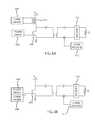
- FIGS. 6A-Care simplified diagrams that include mechanisms for affecting this kind of data transfer. Certain components illustrated in other figures are omitted from FIGS. 6A-C to simplifying the drawings. Specifically, FIGS. 6A-C shows a rectifier 152 , while other components of the internal assembly 108 are omitted. Similarly, FIGS. 6A-C shows a power driver 604 and a power transistor 404 , while other components of the external assembly 104 are omitted.
- the power driver 604may be a controller 124 or other component that drives the various transistors associated with the inverter 116 , as described above in connection with FIG. 4 . Only one transistor 404 is shown in FIGS. 6A-C in order to simplify the drawing.
- FIGS. 6A-Calso shows a communication driver 608 that is configured to transmit a data signal through the skin 264 of the subject.
- the communication driver 608is located on the primary side and is configured to transmit a data signal that is received at the implanted secondary.
- the communication driver 608is located on the secondary side and is configured to transmit a data signal that is received at the external primary.
- the communication driver 608is connected to the transistor 404 and is configured to encode a data signal into the power signal output by the transistor 404 .
- the communication driver 608may modulate an attribute of the power signal as power is transferred from the external primary to the implanted secondary. Attributes of the power signal that the communication driver 608 may modulate include the amplitude, the frequency, and/or the phase.
- the power signalmay be demodulated by a communication receiver 612 so as to extract the data signal.
- the communication driver 608may operate to transmit the data signal through the skin of the patient during either the power mode or the idle mode.
- FIG. 6Ashows an implementation where the communication driver 608 is connected to the drain of the power transistor 404 through a transformer 616 .
- the primary side of the transformer 616may be connected to the communication driver 608 .
- the secondary side of the transformer 616connects the DC power source to the drain or the high side of the power transistor 404 .
- the communication driver 608may modulate the power signal output from the transistor 404 .
- FIG. 6Bshows an implementation where the communication driver 608 is connected to or otherwise associated with the power driver 604 .
- the communication driver 608alters the output of the power driver so as to modulate the power signal output from the transistor 404 .
- the communication driver 608modulates the drive signal output from the power driver 604 .
- the modulated drive signalis then received as input at the transistor 404 , which then outputs a modulated power signal.
- the communication driver 608may transmit data by modulating the amplitude of the power signal that is output from the power transistor 404 .
- the communication driver 608may modulate the amplitude of the power signal while the system 100 is operating in either the power supply mode or in the idle mode.
- FIG. 7is an illustration of example signal traces that show an amplitude modulation by the communication driver 608 .
- FIG. 7shows an amplitude modulation that occurs when the system is operating in power supply mode.
- FIG. 7shows a primary side voltage signal 704 encoded with a plurality of symbols 708 represented by different signal amplitudes. The different signal amplitudes are injected into the primary side voltage signal 704 through the operation of the communication driver 608 .
- different signal amplitudesmay be coupled into the power signal through the transformer 616 .
- different signal amplitudesmay be produced by the power driver 604 being driven by different amounts.
- the primary voltage signal 704induces the current signal 712 in the secondary.
- the encoded data signalis also transmitted to the secondary.
- the secondary side current signal 712is encoded with a plurality of symbols 708 represented by the different signal amplitudes.
- the secondary side signal 712may be received at the communication receiver 612 , which may demodulate the signal 712 so as to extract the encoded data represented by the various symbols 708 .
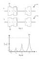
- the communication driver 608may also indirectly modulate the amplitude of the power signal by shifting the power signal among different subharmonics of the fundamental drive frequency.
- FIG. 8Ais an illustration of the secondary current gain response to the communication driver's 608 use of subharmonic frequencies.
- FIG. 8Bshows a primary side voltage signal 804 encoded with a plurality of symbols 808 that correspond to different subharmonics.
- the primary side voltage signal 804is driven at different subharmonics by an operation of the communication driver 608 that modifies the output of the power driver 604 .
- the primary voltage signal 804induces a current signal in the secondary, which also transmits the encoded data to the secondary.
- This secondary side current signalmay be received at the communication receiver 612 , which may demodulate the signal so as to extract the encoded data.
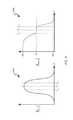
- FIG. 9is a graph of the frequency response of an example system 100 in accordance with embodiment discussed herein for power supply mode.
- FIG. 9includes a first plot 904 of gain versus frequency, and a second plot 908 of phase versus frequency for the example system 100 .
- FIG. 9shows a relatively wide bandwidth. Specifically, as operating frequency is changed the system's 100 gain and phase remains substantially the same. The system can support about 20 kHz of variance before the system starts to exhibit any major changes to performance.
- the communication driver 608can encode data into the inductive channel between the primary and secondary by dithering the operating frequency about +/ ⁇ 10 kHz around a nominal frequency.
- the communication driver 608may modulate the frequency of the power signal while the system 100 is operating in either the power supply mode or in the idle mode.
- FIG. 10is an illustration of example signal traces that show a frequency modulation by the communication driver 608 .
- FIG. 10shows a frequency modulation that occurs when the system is operating in power supply mode.
- FIG. 10shows a primary side voltage signal 1004 encoded with a plurality of symbols 1008 represented by different signal frequencies. The different signal frequencies are injected into the primary side voltage signal 1004 through the operation of the communication driver 608 . Specifically, in the configuration of FIG. 6B , different signal frequencies may be produced by the power driver 604 being driven by different amounts.
- the primary voltage signal 1004induces the current signal 1012 in the secondary.
- the encoded data signalis also transmitted to the secondary.
- FIG. 10shows a frequency modulation that occurs when the system is operating in power supply mode.
- FIG. 10shows a primary side voltage signal 1004 encoded with a plurality of symbols 1008 represented by different signal frequencies. The different signal frequencies are injected into the primary side voltage signal 1004 through the operation of the communication driver 608 . Specifically, in
- the secondary side current signal 1012is encoded with a plurality of symbols 1008 represented by the different signal frequencies.
- the secondary side signal 1012may be received at the communication receiver 612 , which may demodulate the signal 1012 so as to extract the encoded data represented by the various symbols 1008 .
- the communication driver 608may also transmit data by modulating the phase of the power signal that is output from the power transistor 404 .
- the systemalternates between a power supply mode and an idle mode.
- the idle modethe inductive link between the primary and the secondary is shut off at least for a short period of time. Because of this shut-off, consecutive power modes are not synchronized.
- phase informationcan be varied from one power cycle to another by the communication driver 608 . In this way, phase information of the signal in the power supply mode can be used to transmit data.
- FIG. 11is an illustration of example signal traces that show a phase modulation by the communication driver 608 .
- FIG. 11shows a primary side voltage signal 1104 encoded with a plurality of symbols 1108 represented by different phase angles. The different phase angles are injected into the primary side voltage signal 1104 through the operation of the communication driver 608 .
- the communication driver 608sets the phase angle for the primary side voltage signal 1104 .
- the primary voltage signal 1104induces the current signal 1112 in the secondary.
- the encoded data signalis also transmitted to the secondary.
- the secondary side current signal 1112is encoded with a plurality of symbols 1108 represented by the different phase angles.
- the secondary side signal 1112may be received at the communication receiver 612 , which may demodulate the signal 1112 over a plurality of power cycles so as to extract the encoded data represented by the various symbols 1108 .
- Upstream data communicationCommunicating data from the external primary to the implanted secondary as discussed above, is referred to herein as “upstream” data communication.
- Examples of “downstream” communication where data is communicated from the implanted secondary to the external primaryare provided in the following United States patents, the entirety of which patents are hereby incorporated by reference: U.S. Pat. Nos. 6,579,315; 6,478,820; 6,458,164; and 6,451,055.
- these patentsinclude disclosure of downstream communication embodiments that use amplitude shift keying, or amplitude modulation, from the secondary to the primary during a power supply mode portion of a power cycle.
- system and methods for communicating data downstream during the idle mode portion of the power cycleare system and methods for communicating data downstream during the idle mode portion of the power cycle. Specifically, data may be communicated from the implanted secondary to the external primary during the idle mode using amplitude or phase modulation. In addition, data may be communicated downstream using load modulation during a power supply mode portion of a power
- FIG. 6Cis a simplified circuit diagram that includes a mechanism for affecting data transfer from the implanted secondary to the external primary.
- the communication driver 608is connected to the internal resonant network 128 through a switch 616 , which in turn, is connected to a load element 620 .
- the switch 616couples the load element 620 into the internal resonant network 128 .
- the switch 616is in the closed position, the load element 620 is decoupled from internal resonant network 128 .
- the communication driver 608encodes a data signal into the power transfer that is occurring across the inductive link between the primary and the secondary.
- the communication driver 608modulates the electrical load presented by the implanted secondary by switching the load element 620 in and out of the internal resonant network 128
- the primary 120 and secondary resonant networks 128do not exchange significant amount of power and are free to exchange data with minimal detriment to power transfer.
- the secondary resonant network 128can be modulated to reflect impedance changes back to the primary.
- the load element 620is resistive and impedance changes are reflected back to the primary by resistive loading of the secondary resonant network 128 .
- data communicationis achieved by switching in and out a small resistor into the secondary resonant network 128 . As a result, the resistive loading is reflected in the primary current.
- the load element 620is reactive and the system implements reactive loading of the secondary resonant network 128 .
- data communicationis achieved by switching in and out a small reactive component, (such as a capacitor) into the secondary resonant network 128 .
- a small reactive componentsuch as a capacitor
- both “upstream” and “downstream” communicationmay occur in the system 100 .
- the system 100may implement two way data communication.
- the power transfer signal or the channel between the primary and the secondarymay be modulated by a first and second data signal, where the first signal is encoded at the primary and received at the secondary, and the second signal is encoded at the secondary and received at the primary.
- the first and second data signalsare time multiplexed such each is transmitted during its own dedicated time interval.
- the first and second data signalsare transmitted simultaneously. It has been found that upstream amplitude modulation can be transmitted simultaneously with downstream amplitude modulation. Upstream frequency modulation can be transmitted simultaneously with downstream amplitude modulation. Similarly, upstream phase modulation be transmitted simultaneously with downstream amplitude modulation.
Landscapes
- Health & Medical Sciences (AREA)
- Engineering & Computer Science (AREA)
- Heart & Thoracic Surgery (AREA)
- General Health & Medical Sciences (AREA)
- Veterinary Medicine (AREA)
- Biomedical Technology (AREA)
- Public Health (AREA)
- Animal Behavior & Ethology (AREA)
- Life Sciences & Earth Sciences (AREA)
- Cardiology (AREA)
- Hematology (AREA)
- Anesthesiology (AREA)
- Mechanical Engineering (AREA)
- Computer Networks & Wireless Communication (AREA)
- Signal Processing (AREA)
- Power Engineering (AREA)
- Radiology & Medical Imaging (AREA)
- Nuclear Medicine, Radiotherapy & Molecular Imaging (AREA)
- Physics & Mathematics (AREA)
- Electromagnetism (AREA)
- Acoustics & Sound (AREA)
- Near-Field Transmission Systems (AREA)
- Charge And Discharge Circuits For Batteries Or The Like (AREA)
Abstract
Description
Claims (9)
Priority Applications (2)
| Application Number | Priority Date | Filing Date | Title |
|---|---|---|---|
| US14/995,962US10406267B2 (en) | 2015-01-16 | 2016-01-14 | Data communication in a transcutaneous energy transfer system |
| US16/564,210US11235141B2 (en) | 2015-01-16 | 2019-09-09 | Data communication in a transcutaneous energy transfer system |
Applications Claiming Priority (2)
| Application Number | Priority Date | Filing Date | Title |
|---|---|---|---|
| US201562104451P | 2015-01-16 | 2015-01-16 | |
| US14/995,962US10406267B2 (en) | 2015-01-16 | 2016-01-14 | Data communication in a transcutaneous energy transfer system |
Related Child Applications (1)
| Application Number | Title | Priority Date | Filing Date |
|---|---|---|---|
| US16/564,210DivisionUS11235141B2 (en) | 2015-01-16 | 2019-09-09 | Data communication in a transcutaneous energy transfer system |
Publications (2)
| Publication Number | Publication Date |
|---|---|
| US20160206799A1 US20160206799A1 (en) | 2016-07-21 |
| US10406267B2true US10406267B2 (en) | 2019-09-10 |
Family
ID=56293264
Family Applications (2)
| Application Number | Title | Priority Date | Filing Date |
|---|---|---|---|
| US14/995,962Active2036-08-19US10406267B2 (en) | 2015-01-16 | 2016-01-14 | Data communication in a transcutaneous energy transfer system |
| US16/564,210Active2036-04-03US11235141B2 (en) | 2015-01-16 | 2019-09-09 | Data communication in a transcutaneous energy transfer system |
Family Applications After (1)
| Application Number | Title | Priority Date | Filing Date |
|---|---|---|---|
| US16/564,210Active2036-04-03US11235141B2 (en) | 2015-01-16 | 2019-09-09 | Data communication in a transcutaneous energy transfer system |
Country Status (2)
| Country | Link |
|---|---|
| US (2) | US10406267B2 (en) |
| DE (1) | DE102016100534A1 (en) |
Cited By (4)
| Publication number | Priority date | Publication date | Assignee | Title |
|---|---|---|---|---|
| US10898628B2 (en) | 2014-07-25 | 2021-01-26 | Minnetronix, Inc. | Coil parameters and control |
| US11207516B2 (en) | 2015-01-14 | 2021-12-28 | Minnetronix, Inc. | Distributed transformer |
| US11235141B2 (en) | 2015-01-16 | 2022-02-01 | Minnetronix, Inc. | Data communication in a transcutaneous energy transfer system |
| US11894695B2 (en) | 2015-04-14 | 2024-02-06 | Minnetronix, Inc. | Repeater resonator |
Families Citing this family (8)
| Publication number | Priority date | Publication date | Assignee | Title |
|---|---|---|---|---|
| DE102015112097A1 (en) | 2014-07-25 | 2016-01-28 | Minnetronix, Inc. | power scale |
| US10873221B1 (en)* | 2017-01-31 | 2020-12-22 | Apple Inc. | Wireless power control system |
| JP7065371B2 (en)* | 2017-03-03 | 2022-05-12 | パナソニックIpマネジメント株式会社 | Power transmission system |
| US11602627B2 (en) | 2018-03-20 | 2023-03-14 | Second Heart Assist, Inc. | Circulatory assist pump |
| US10847979B2 (en)* | 2018-12-14 | 2020-11-24 | Zhuhai Jieli Technology Co., Ltd | Charging and communication system |
| EP3922299A1 (en)* | 2020-06-11 | 2021-12-15 | Berlin Heart GmbH | Connection system for energy and / or data transmission from and / or to an implantable blood pump and cardiac assistance system |
| US12036399B2 (en)* | 2020-09-15 | 2024-07-16 | Medtronic, Inc. | Coil shunting for voltage limiting of inductively transferred power |
| FR3145290B1 (en) | 2023-01-27 | 2025-04-04 | Fineheart | Transcutaneous energy transmission system intended to power an implant. |
Citations (239)
| Publication number | Priority date | Publication date | Assignee | Title |
|---|---|---|---|---|
| US3195540A (en) | 1963-03-29 | 1965-07-20 | Louis C Waller | Power supply for body implanted instruments |
| US3566876A (en) | 1967-12-14 | 1971-03-02 | Hewlett Packard Co | Defibrillator |
| US3756246A (en) | 1971-07-15 | 1973-09-04 | American Optical Corp | Apparatus for externally determining actual output of an implanted energy source |
| US3760332A (en) | 1972-03-09 | 1973-09-18 | American Optical Corp | Pacer connector |
| US3806807A (en) | 1971-10-27 | 1974-04-23 | Fujitsu Ltd | Digital communication system with reduced intersymbol interference |
| US3943535A (en) | 1972-12-20 | 1976-03-09 | Fuji Photo Film Co., Ltd. | Film casette |
| US4143661A (en) | 1977-12-12 | 1979-03-13 | Andros Incorporated | Power supply for body implant and method for operation |
| US4164946A (en) | 1977-05-27 | 1979-08-21 | Mieczyslaw Mirowski | Fault detection circuit for permanently implanted cardioverter |
| US4221543A (en) | 1977-11-07 | 1980-09-09 | Renal Systems, Inc. | Bloom pump system |
| US4233546A (en) | 1978-04-26 | 1980-11-11 | Hydro-Quebec | Stroboscopic beacons fed from a capacitive source |
| US4237895A (en) | 1979-04-20 | 1980-12-09 | Medcor, Inc. | Control signal transmitter and monitor for implanted pacer |
| US4263642A (en) | 1979-03-28 | 1981-04-21 | Litton Systems, Inc. | DC to DC converter |
| US4361153A (en) | 1980-05-27 | 1982-11-30 | Cordis Corporation | Implant telemetry system |
| WO1983001006A1 (en) | 1981-09-18 | 1983-03-31 | Hochmair, Ingeborg, J. | Transcutaneous signal transmission system and methods |
| US4417349A (en) | 1979-11-08 | 1983-11-22 | Digital Broadcasting Corporation | SCA Data transmission system with a raised cosine filter |
| US4439806A (en) | 1981-03-12 | 1984-03-27 | Siemens Aktiengesellschaft | Short-circuit protection device for a DC control element |
| US4446513A (en) | 1980-06-13 | 1984-05-01 | La Telemecanique Electrique | DC/AC Bridge inverter including a switching aid and inductive energy recovery circuit |
| US4453537A (en) | 1981-08-04 | 1984-06-12 | Spitzer Daniel E | Apparatus for powering a body implant device |
| US4469104A (en) | 1982-07-16 | 1984-09-04 | Cordis Corporation | Multipolar connector for pacing lead |
| US4494545A (en) | 1980-05-27 | 1985-01-22 | Cordis Corporation | Implant telemetry system |
| US4532932A (en) | 1984-01-03 | 1985-08-06 | Cordis Corporation | Implant communication system with frequency shift means |
| US4561443A (en) | 1983-03-08 | 1985-12-31 | The Johns Hopkins University | Coherent inductive communications link for biomedical applications |
| US4625730A (en) | 1985-04-09 | 1986-12-02 | The Johns Hopkins University | Patient ECG recording control for an automatic implantable defibrillator |
| WO1987000420A1 (en) | 1985-07-22 | 1987-01-29 | Novacor Medical Corporation | Implantable blood pump and method of operation |
| FR2587221A1 (en) | 1985-01-31 | 1987-03-20 | Houri Andre | Extracochlear implant system with variation of the quantity of excitation current by pulse width modulation (control electronics). The implanted transmitter/receiver coupling is by coils having magnetic cores (or by air) |
| US4681111A (en) | 1985-04-05 | 1987-07-21 | Siemens-Pacesetter, Inc. | Analog and digital telemetry system for an implantable device |
| US4691270A (en) | 1986-07-22 | 1987-09-01 | Rca Corporation | Current fed inverter bridge with lossless snubbers |
| US4706689A (en) | 1985-10-30 | 1987-11-17 | Daniel Man | Implantable homing device |
| US4768512A (en) | 1986-05-13 | 1988-09-06 | Mieczyslaw Mirowski | Cardioverting system and method with high-frequency pulse delivery |
| US4774950A (en) | 1987-10-06 | 1988-10-04 | Leonard Bloom | Hemodynamically responsive system for and method of treating a malfunctioning heart |
| US4848346A (en) | 1987-12-02 | 1989-07-18 | Siemens-Pacesetter, Inc. | Pacemaker connector system |
| US4855888A (en) | 1988-10-19 | 1989-08-08 | Unisys Corporation | Constant frequency resonant power converter with zero voltage switching |
| US4898173A (en) | 1988-04-22 | 1990-02-06 | Medtronic, Inc. | In-line pacemaker connector system |
| US4924171A (en) | 1987-10-08 | 1990-05-08 | Tokyo Keiki Co., Ltd. | System for supplying power source by electromagnetic induction coupling |
| US4925443A (en) | 1987-02-27 | 1990-05-15 | Heilman Marlin S | Biocompatible ventricular assist and arrhythmia control device |
| US4933798A (en) | 1987-10-22 | 1990-06-12 | Widmayer R&D Ventures | Self protecting and automatic resetting capacitor synchronous switch apparatus for control of AC power to inductive loads |
| US4941201A (en) | 1985-01-13 | 1990-07-10 | Abbott Laboratories | Electronic data storage and retrieval apparatus and method |
| US4941652A (en) | 1987-02-09 | 1990-07-17 | Nintendo Co., Ltd. | Bicycle type training machine |
| US4947844A (en) | 1984-09-07 | 1990-08-14 | The University Of Melbourne | Receiver/stimulator for hearing prosthesis |
| US4953068A (en) | 1989-11-08 | 1990-08-28 | Unisys Corporation | Full bridge power converter with multiple zero voltage resonant transition switching |
| US4964027A (en) | 1989-12-05 | 1990-10-16 | Sundstrand Corporation | High efficiency power generating system |
| US4979506A (en) | 1989-08-08 | 1990-12-25 | Siemens-Pacesetter, Inc. | Self-test system and method for external programming device |
| US5012807A (en) | 1990-05-03 | 1991-05-07 | Siemens-Pacesetter, Inc. | Multi-part molded pacemaker connector and method of making same |
| US5076270A (en) | 1990-05-03 | 1991-12-31 | Siemens-Pacesetter, Inc. | Apparatus and method for making electrical connections in an implantable pacemaker |
| US5132889A (en) | 1991-05-15 | 1992-07-21 | Ibm Corporation | Resonant-transition DC-to-DC converter |
| US5132888A (en) | 1991-01-07 | 1992-07-21 | Unisys Corporation | Interleaved bridge converter |
| US5157593A (en) | 1990-12-13 | 1992-10-20 | Northern Telecom Limited | Constant frequency resonant dc/dc converter |
| US5158097A (en) | 1990-06-08 | 1992-10-27 | Allegheny-Singer Research Institute | Paraneural stimulating lead |
| US5205810A (en) | 1990-10-15 | 1993-04-27 | Medtronic, Inc. | Muscle powered cardiac assist system |
| US5279292A (en) | 1991-02-13 | 1994-01-18 | Implex Gmbh | Charging system for implantable hearing aids and tinnitus maskers |
| US5314457A (en)* | 1993-04-08 | 1994-05-24 | Jeutter Dean C | Regenerative electrical |
| US5327335A (en) | 1992-09-28 | 1994-07-05 | Sundstrand Corporation | Harmonic feedback control for an inverter |
| US5345375A (en) | 1991-12-16 | 1994-09-06 | Regents Of The University Of Minnesota | System and method for reducing harmonic currents by current injection |
| US5350413A (en) | 1990-06-21 | 1994-09-27 | The University Of Ottawa | Transcutaneous energy transfer device |
| US5400235A (en) | 1992-08-07 | 1995-03-21 | International Business Machines Corp. | High frequency energy saving DC to DC power converter |
| US5413595A (en) | 1993-10-15 | 1995-05-09 | Pacesetter, Inc. | Lead retention and seal for implantable medical device |
| US5438498A (en) | 1993-12-21 | 1995-08-01 | Raytheon Company | Series resonant converter having a resonant snubber |
| US5444608A (en) | 1994-04-14 | 1995-08-22 | Northern Telecom Limited | High frequency power distribution system |
| US5456715A (en) | 1993-05-21 | 1995-10-10 | Liotta; Domingo S. | Implantable mechanical system for assisting blood circulation |
| US5499178A (en) | 1991-12-16 | 1996-03-12 | Regents Of The University Of Minnesota | System for reducing harmonics by harmonic current injection |
| US5500004A (en) | 1994-11-08 | 1996-03-19 | Telectronics Pacing Systems, Inc. | Cardio myostimulation system with defibrillation |
| US5515264A (en) | 1992-05-11 | 1996-05-07 | Electric Power Research Institute, Inc. | Optimized high power voltage sourced inverter system |
| US5522865A (en) | 1989-09-22 | 1996-06-04 | Alfred E. Mann Foundation For Scientific Research | Voltage/current control system for a human tissue stimulator |
| US5559689A (en) | 1994-08-08 | 1996-09-24 | Sundstrand Corporation | Harmonic content determination apparatus |
| US5569156A (en) | 1993-09-10 | 1996-10-29 | Ottawa Heart Institute Research Corporation | Electrohydraulic ventricular assist device |
| US5569307A (en) | 1989-09-22 | 1996-10-29 | Alfred E. Mann Foundation For Scientific Research | Implantable cochlear stimulator having backtelemetry handshake signal |
| US5584870A (en) | 1995-03-09 | 1996-12-17 | Cochlear Ltd. | Implant ESD protection network |
| US5594635A (en) | 1993-03-30 | 1997-01-14 | Motorola, Inc. | Constant frequency, zero-voltage-switching converters with resonant switching bridge |
| US5630836A (en) | 1995-01-19 | 1997-05-20 | Vascor, Inc. | Transcutaneous energy and information transmission apparatus |
| US5662692A (en) | 1994-12-09 | 1997-09-02 | Pacesetter, Inc. | Cardiac defibrillator having selectable polarity case |
| US5674281A (en) | 1996-01-30 | 1997-10-07 | The Penn State Research Foundation | Artificial heart braking system |
| US5690693A (en) | 1995-06-07 | 1997-11-25 | Sulzer Intermedics Inc. | Transcutaneous energy transmission circuit for implantable medical device |
| US5702431A (en) | 1995-06-07 | 1997-12-30 | Sulzer Intermedics Inc. | Enhanced transcutaneous recharging system for battery powered implantable medical device |
| US5702427A (en) | 1996-03-28 | 1997-12-30 | Medtronic, Inc. | Verification of capture using pressure waves transmitted through a pacing lead |
| US5713954A (en) | 1995-06-13 | 1998-02-03 | Abiomed R&D, Inc. | Extra cardiac ventricular assist device |
| US5713939A (en)* | 1996-09-16 | 1998-02-03 | Sulzer Intermedics Inc. | Data communication system for control of transcutaneous energy transmission to an implantable medical device |
| US5722930A (en) | 1992-08-06 | 1998-03-03 | Electric Boat Corporation | Reciprocating pump circulatory assist arrangement |
| WO1998009588A1 (en) | 1996-09-04 | 1998-03-12 | Cochlear Limited | Compact inductive arrangement |
| US5728154A (en) | 1996-02-29 | 1998-03-17 | Minnesota Mining And Manfacturing Company | Communication method for implantable medical device |
| US5735887A (en)* | 1996-12-10 | 1998-04-07 | Exonix Corporation | Closed-loop, RF-coupled implanted medical device |
| US5741314A (en) | 1995-10-19 | 1998-04-21 | Daly; Christopher Newton | Embedded data link and protocol |
| US5741316A (en) | 1996-12-02 | 1998-04-21 | Light Sciences Limited Partnership | Electromagnetic coil configurations for power transmission through tissue |
| US5749909A (en) | 1996-11-07 | 1998-05-12 | Sulzer Intermedics Inc. | Transcutaneous energy coupling using piezoelectric device |
| US5751125A (en) | 1995-11-08 | 1998-05-12 | The Penn State Research Foundation | Artificial heart with sensorless motor |
| US5755748A (en) | 1996-07-24 | 1998-05-26 | Dew Engineering & Development Limited | Transcutaneous energy transfer device |
| US5781419A (en) | 1996-04-12 | 1998-07-14 | Soft Switching Technologies, Inc. | Soft switching DC-to-DC converter with coupled inductors |
| US5945762A (en) | 1998-02-10 | 1999-08-31 | Light Sciences Limited Partnership | Movable magnet transmitter for inducing electrical current in an implanted coil |
| US5948006A (en) | 1998-10-14 | 1999-09-07 | Advanced Bionics Corporation | Transcutaneous transmission patch |
| US5991665A (en) | 1997-09-18 | 1999-11-23 | Sulzer Intermedics Inc. | Self-cooling transcutaneous energy transfer system for battery powered implantable device |
| US5995874A (en) | 1998-02-09 | 1999-11-30 | Dew Engineering And Development Limited | Transcutaneous energy transfer device |
| US6047214A (en) | 1998-06-09 | 2000-04-04 | North Carolina State University | System and method for powering, controlling, and communicating with multiple inductively-powered devices |
| US6058330A (en) | 1998-03-06 | 2000-05-02 | Dew Engineering And Development Limited | Transcutaneous energy transfer device |
| US6067474A (en) | 1997-08-01 | 2000-05-23 | Advanced Bionics Corporation | Implantable device with improved battery recharging and powering configuration |
| US6076016A (en) | 1995-10-19 | 2000-06-13 | Feierbach; Gary F. | Galvanic transdermal conduction communication system and method |
| US6088619A (en) | 1999-02-26 | 2000-07-11 | Implex Aktiengesellschaft Hearing Technology | Device and method for aiding the positioning of an external part relative to an implantable part of a charging system for an implantable medical device |
| US6112121A (en) | 1998-09-09 | 2000-08-29 | Intermedics Inc. | Implantable medical device with positive indication of lead connection and connector therefor |
| US6149683A (en) | 1998-10-05 | 2000-11-21 | Kriton Medical, Inc. | Power system for an implantable heart pump |
| US6212430B1 (en) | 1999-05-03 | 2001-04-03 | Abiomed, Inc. | Electromagnetic field source with detection of position of secondary coil in relation to multiple primary coils |
| US6233485B1 (en) | 1999-06-14 | 2001-05-15 | Intermedics Inc. | Methods and apparatus for tachycardia rate hysteresis for dual-chamber cardiac stimulators |
| US6240318B1 (en) | 1998-10-27 | 2001-05-29 | Richard P. Phillips | Transcutaneous energy transmission system with full wave Class E rectifier |
| US6254525B1 (en) | 1998-11-04 | 2001-07-03 | Cardio Technologies, Inc. | Cardiac assist system and method thereof |
| US6275737B1 (en) | 1998-10-14 | 2001-08-14 | Advanced Bionics Corporation | Transcutaneous transmission pouch |
| US6324430B1 (en) | 1998-07-06 | 2001-11-27 | Abiomed, Inc. | Magnetic shield for primary coil of transcutaneous energy transfer device |
| WO2001091678A1 (en) | 2000-05-30 | 2001-12-06 | Otologics Llc | Connector for implantable hearing aid |
| US6342071B1 (en) | 1999-07-08 | 2002-01-29 | Benjamin David Pless | Ambulatory blood pump |
| US20020021226A1 (en) | 2000-08-08 | 2002-02-21 | Philippe Clement | Electrical apparatus comprising a monitoring device, support and monitoring device for such an apparatus, and electrical installation incorporating them |
| US20020032471A1 (en)* | 2000-09-06 | 2002-03-14 | Loftin Scott M. | Low-power, high-modulation-index amplifier for use in battery-powered device |
| US6389318B1 (en) | 1998-07-06 | 2002-05-14 | Abiomed, Inc. | Magnetic shield for primary coil of transcutaneous energy transfer device |
| US20020087204A1 (en) | 2001-01-04 | 2002-07-04 | Kung Robert T. V. | Flexible transcutaneous energy transfer (TET) primary coil |
| US6424867B1 (en) | 1999-09-30 | 2002-07-23 | Pacesetter, Inc. | Secure telemetry system and method for an implantable cardiac stimulation device |
| US6434194B1 (en) | 1997-11-05 | 2002-08-13 | Wherenet Corp | Combined OOK-FSK/PPM modulation and communication protocol scheme providing low cost, low power consumption short range radio link |
| US6442434B1 (en) | 1999-10-19 | 2002-08-27 | Abiomed, Inc. | Methods and apparatus for providing a sufficiently stable power to a load in an energy transfer system |
| US6443891B1 (en) | 2000-09-20 | 2002-09-03 | Medtronic, Inc. | Telemetry modulation protocol system for medical devices |
| US6451055B1 (en) | 2000-04-25 | 2002-09-17 | The Penn State Research Foundation | Artificial heart data communication system |
| US6458164B1 (en) | 2000-04-25 | 2002-10-01 | The Penn State Research Foundation | Artificial heart with energy recovery |
| US6478820B1 (en) | 2000-04-25 | 2002-11-12 | The Penn State Research Foundation | Artificial heart with synchronous rectification |
| US20020177884A1 (en) | 2001-05-23 | 2002-11-28 | Ahn Tae Young | Apparatus for contactless power transfer for implantable medical device |
| US20030045912A1 (en) | 2001-09-05 | 2003-03-06 | Medtronic, Inc. | Medical lead connector |
| US20030085684A1 (en) | 2001-11-07 | 2003-05-08 | Quallion Llc | Implantable medical power module |
| US6579315B1 (en) | 2000-04-25 | 2003-06-17 | The Penn State Research Foundation | Artificial heart power supply system |
| US20030171792A1 (en) | 1998-07-06 | 2003-09-11 | Farhad Zarinetchi | Transcutaneous energy transfer module with integrated conversion circuitry |
| US6648914B2 (en) | 1999-11-29 | 2003-11-18 | Epic Biosonics Inc. | Totally implantable cochlear prosthesis |
| US6671554B2 (en) | 2001-09-07 | 2003-12-30 | Medtronic Minimed, Inc. | Electronic lead for a medical implant device, method of making same, and method and apparatus for inserting same |
| US20040034393A1 (en) | 2002-08-16 | 2004-02-19 | Cardiac Pacemakers, Inc. | Connector port construction technique for implantable medical device |
| US20040039423A1 (en) | 2002-08-20 | 2004-02-26 | Alexander Dolgin | Transmission of information from an implanted medical device |
| US20040049245A1 (en) | 2002-09-09 | 2004-03-11 | Volker Gass | Autonomous patch for communication with an implantable device, and medical kit for using said patch |
| US6810289B1 (en) | 2000-04-20 | 2004-10-26 | Cochlear Limited | Transcutaneous power optimization circuit for cochlear implant |
| US6831944B1 (en) | 1999-09-14 | 2004-12-14 | Interdigital Technology Corporation | Reduced computation in joint detection |
| US6850803B1 (en) | 2000-06-16 | 2005-02-01 | Medtronic, Inc. | Implantable medical device with a recharging coil magnetic shield |
| US6862478B1 (en) | 2002-06-14 | 2005-03-01 | Pacesetter, Inc. | Connector top for implantable medical device |
| US20050065570A1 (en) | 2001-02-21 | 2005-03-24 | Medtronic, Inc. | Medical lead and lead connector system |
| US20050075696A1 (en) | 2003-10-02 | 2005-04-07 | Medtronic, Inc. | Inductively rechargeable external energy source, charger, system and method for a transcutaneous inductive charger for an implantable medical device |
| US20050075694A1 (en) | 2003-10-02 | 2005-04-07 | Medtronic, Inc. | External power source, charger and system for an implantable medical device having thermal characteristics and method therefore |
| US20050245996A1 (en) | 2004-04-30 | 2005-11-03 | Medtronic, Inc. | Spacers for use with transcutaneous energy transfer system |
| US6978181B1 (en) | 2002-05-24 | 2005-12-20 | Pacesetter, Inc. | Inter-programmer communication among programmers of implantable medical devices |
| US20050288739A1 (en) | 2004-06-24 | 2005-12-29 | Ethicon, Inc. | Medical implant having closed loop transcutaneous energy transfer (TET) power transfer regulation circuitry |
| US20050288741A1 (en) | 2004-06-24 | 2005-12-29 | Ethicon Endo-Surgery, Inc. | Low frequency transcutaneous energy transfer to implanted medical device |
| US20060020305A1 (en) | 2004-06-24 | 2006-01-26 | Ethicon Endo-Surgery, Inc. | Spatially decoupled twin secondary coils for optimizing transcutaneous energy transfer (TET) power transfer characteristics |
| US20060036127A1 (en) | 2004-08-13 | 2006-02-16 | Delgado Reynolds M Iii | Method and apparatus for long-term assisting a left ventricle to pump blood |
| US7003353B1 (en) | 2002-12-10 | 2006-02-21 | Quallion Llc | Photovoltaic powered charging apparatus for implanted rechargeable batteries |
| US7035689B1 (en) | 2002-10-14 | 2006-04-25 | Pacesetter, Inc. | Connector and retention mechanism for an implantable medical device |
| US7069086B2 (en) | 2002-08-08 | 2006-06-27 | Cardiac Pacemakers, Inc. | Method and system for improved spectral efficiency of far field telemetry in a medical device |
| US7076206B2 (en) | 2001-04-20 | 2006-07-11 | Koninklijke Philips Electronics, N.V. | System for wireless transmission of electrical power, a garment, a system of garments and method for the transmission of signals and/or electrical energy |
| US20060167333A1 (en) | 2002-08-09 | 2006-07-27 | Moore Daniel R | Inflow conduit for ventricular assist device |
| US20060184204A1 (en) | 2005-02-11 | 2006-08-17 | Advanced Bionics Corporation | Implantable microstimulator having a separate battery unit and methods of use thereof |
| US20060247737A1 (en) | 2005-04-29 | 2006-11-02 | Medtronic, Inc. | Alignment indication for transcutaneous energy transfer |
| US20060267790A1 (en) | 2005-05-24 | 2006-11-30 | Dräger Safety AG & Co. KGaA | Modular system for electronic assembly units worn close to the body |
| US7173411B1 (en) | 2004-09-30 | 2007-02-06 | Rockwell Automation Technologies, Inc. | Inductive proximity sensor using coil time constant for temperature compensation |
| DE102006037668A1 (en) | 2005-08-16 | 2007-03-01 | Zarlink Semiconductor Ab | Communication system for use in e.g. in-vivo medical electronic device for human and animals has switch that operates communication mode and power conversion mode by selectively connecting inductive coil to receiver or power converter |
| US20070060787A1 (en) | 2003-10-31 | 2007-03-15 | Sunshine Heart Company Pty Ltd. | Synchronization control system |
| US20070255349A1 (en) | 2006-04-28 | 2007-11-01 | Medtronic, Inc. | Antenna for an external power source for an implantable medical device, system and method |
| WO2007126454A2 (en) | 2006-04-28 | 2007-11-08 | Medtronic, Inc. | System for transcutaneous energy transfer to an implantable medical device with mating elements |
| US7299095B1 (en) | 2003-12-17 | 2007-11-20 | Pacesetter, Inc. | Electrical contact assembly |
| US7317947B2 (en) | 2003-05-16 | 2008-01-08 | Medtronic, Inc. | Headset recharger for cranially implantable medical devices |
| US20080198947A1 (en) | 2007-02-15 | 2008-08-21 | Zierhofer Clemens M | Inductive Power and Data Transmission System Based on Class D and Amplitude Shift Keying |
| WO2008106717A1 (en) | 2007-03-02 | 2008-09-12 | Ventrassist Pty Ltd | Transcutaneous energy transfer system |
| US20080255631A1 (en) | 2007-04-11 | 2008-10-16 | Sjostedt Robbie J | Integrated header connector system |
| US20080303480A1 (en) | 2007-06-05 | 2008-12-11 | Impulse Dynamics Nv | Transcutaneous charging device |
| WO2009029977A1 (en) | 2007-09-03 | 2009-03-12 | Ventrassist Pty Ltd | Transcutaneous energy transfer coil assembly |
| US20090067653A1 (en) | 2007-07-06 | 2009-03-12 | Cochlear Limited | Wireless communication between devices of a hearing prosthesis |
| US7515967B2 (en) | 2003-10-02 | 2009-04-07 | Medtronic, Inc. | Ambulatory energy transfer system for an implantable medical device and method therefore |
| US7574262B2 (en) | 2002-06-21 | 2009-08-11 | Neurodan A/S | Transmitter or receiver mounting |
| US20090281597A1 (en) | 2008-05-08 | 2009-11-12 | Boston Scientific Neuromodulation Corporation | Transceiver for an implantable medical device having switchable series-to-parallel tank circuit |
| US20100010582A1 (en) | 2008-07-11 | 2010-01-14 | Boston Scientific Neuromodulation Corporation | Medical system and method for setting programmable heat limits |
| US20100033023A1 (en) | 1999-06-21 | 2010-02-11 | Access Business Group International Llc | Adaptive inductive power supply with communication |
| US20100033240A1 (en) | 2007-01-31 | 2010-02-11 | Medtronic, Inc. | Chopper-stabilized instrumentation amplifier for impedance measurement |
| US7672732B2 (en) | 2006-03-31 | 2010-03-02 | University Of Pittsburgh - Of The Commonwealth System Of Higher Education | Portable apparatus that delivers power and information to implantable devices |
| US20100063347A1 (en) | 2008-09-10 | 2010-03-11 | Barry Yomtov | Tet system for implanted medical device |
| US7738965B2 (en) | 2006-04-28 | 2010-06-15 | Medtronic, Inc. | Holster for charging pectorally implanted medical devices |
| US20100164296A1 (en) | 2008-09-27 | 2010-07-01 | Kurs Andre B | Wireless energy transfer using variable size resonators and system monitoring |
| US7781916B2 (en) | 2003-05-26 | 2010-08-24 | Auckland Uniservices Limited | Parallel-tuned pick-up system with multiple voltage outputs |
| US20100249886A1 (en) | 2002-06-28 | 2010-09-30 | Boston Scientific Neuromodulation Corporation | Systems and Methods for Communicating with an Implantable Stimulator |
| US20100292759A1 (en) | 2005-03-24 | 2010-11-18 | Hahn Tae W | Magnetic field sensor for magnetically-coupled medical implant devices |
| WO2010133702A2 (en) | 2010-09-15 | 2010-11-25 | Advanced Bionics Ag | Partially implantable hearing instrument |
| US20100327887A1 (en) | 2007-01-31 | 2010-12-30 | Medtronic, Inc. | Chopper-stabilized instrumentation amplifier for impedance measurement |
| US20110004278A1 (en) | 2009-07-06 | 2011-01-06 | Boston Scientific Neuromodulation Corporation | External Charger for a Medical Implantable Device Using Field Sensing Coils to Improve Coupling |
| US20110093048A1 (en) | 2009-10-15 | 2011-04-21 | Boston Scientific Neuromodulation Corporation | External Charger for a Medical Implantable Device Using Field Inducing Coils to Improve Coupling |
| US20110106210A1 (en) | 2008-04-02 | 2011-05-05 | Werner Meskens | Adjustable transcutaneous energy transfer system |
| US20110101790A1 (en) | 2008-01-18 | 2011-05-05 | Telemetry Research Limited | Selectable resonant frequency transcutaneous energy transfer system |
| US8027735B1 (en) | 2008-04-01 | 2011-09-27 | Advanced Bionics, Llc | Atraumatic high-retention headpiece |
| WO2011119352A1 (en) | 2010-03-26 | 2011-09-29 | Boston Scientific Neuromodulation | Inductive charger with magnetic shielding |
| US8032486B2 (en) | 1999-12-06 | 2011-10-04 | Microstrain, Inc. | Apparatus to receive electromagnetic radiation that penetrates a housing formed of a conductive material |
| US8050068B2 (en) | 2003-05-23 | 2011-11-01 | Auckland Uniservices Limited | Variable reactive element in a resonant converter circuit |
| US20110313490A1 (en) | 2002-06-28 | 2011-12-22 | Boston Scientific Neuromodulation Corporation | Method for Controlling Telemetry in an Implantable Medical Device Based on Power Source Capacity |
| US8093758B2 (en) | 2003-05-23 | 2012-01-10 | Auckland Uniservices Limited | Method and apparatus for control of inductively coupled power transfer systems |
| US8097983B2 (en) | 2005-07-12 | 2012-01-17 | Massachusetts Institute Of Technology | Wireless energy transfer |
| US20120032522A1 (en) | 2008-09-27 | 2012-02-09 | Schatz David A | Wireless energy transfer for implantable devices |
| US8126563B2 (en) | 2001-05-23 | 2012-02-28 | Cochlear Limited | Transceiver coil for auditory prosthesis |
| US20120095528A1 (en) | 2010-10-19 | 2012-04-19 | Miller Iii Scott Allan | Relay interface for connecting an implanted medical device to an external electronics device |
| WO2012077088A2 (en) | 2010-12-10 | 2012-06-14 | Cochlear Limited | Portable power charging of implantable medical devices |
| US20120157754A1 (en) | 2010-12-20 | 2012-06-21 | Abiomed, Inc. | Compact battery and controller module for a transcutaneous energy transfer system |
| US20120157753A1 (en) | 2010-12-20 | 2012-06-21 | Abiomed, Inc. | Transcutaneous energy transfer system with multiple secondary coils |
| US20120154143A1 (en) | 2010-12-20 | 2012-06-21 | Abiomed, Inc. | Transcutaneous energy transfer system with vibration inducing warning circuitry |
| US20120215285A1 (en) | 2011-02-21 | 2012-08-23 | Boston Scientific Neuromodulation Corporation | System for Communication with Implantable Medical Devices Using a Bridge Device |
| US8265770B2 (en) | 2003-10-02 | 2012-09-11 | Medtronic, Inc. | Driver circuitry switchable between energy transfer and telemetry for an implantable medical device |
| US20120265003A1 (en) | 2011-04-14 | 2012-10-18 | Abiomed, Inc. | Transcutaneous energy transfer coil with integrated radio frequency antenna |
| US20130023958A1 (en) | 2011-07-19 | 2013-01-24 | Greatbatch Ltd. | Devices and Methods for Visually Indicating the Alignment of a Transcutaneous Energy Transfer Device Over an Implanted Medical Device |
| US20130046361A1 (en) | 2009-06-30 | 2013-02-21 | Boston Scientific Neuromodulation Corporation | Moldable charger with shape-sensing means for an implantable pulse generator |
| US20130043736A1 (en) | 2011-08-19 | 2013-02-21 | Leviticus Cardio Ltd. | Coplanar energy transfer |
| US8428712B2 (en) | 2004-07-20 | 2013-04-23 | Medtronic, Inc. | Concurrent delivery of treatment therapy with telemetry in an implantable medical device |
| US8428724B2 (en) | 2011-03-11 | 2013-04-23 | Greatbatch Ltd. | Low insertion force electrical connector for implantable medical devices |
| US8437855B2 (en) | 2007-04-09 | 2013-05-07 | Bal Seal Engineering, Inc. | Connector assembly for use with medical devices |
| US20130123881A1 (en) | 2011-11-11 | 2013-05-16 | Boston Scientific Neuromodulation Corporation | External Charger for an Implantable Medical Device System Having a Coil for Communication and Charging |
| US20130127253A1 (en) | 2011-11-21 | 2013-05-23 | Joseph Stark | Transcutaneous power transmission utilizing non-planar resonators |
| US20130158631A1 (en) | 2011-12-16 | 2013-06-20 | Abiomed, Inc. | Automatic power regulation for transcutaneous energy transfer charging system |
| US20130163688A1 (en) | 2000-11-16 | 2013-06-27 | Invensys Systems, Inc. | Control system methods and apparatus for inductive communication across an isolation barrier |
| US8515112B2 (en) | 2003-05-08 | 2013-08-20 | Advanced Bionics, Llc | Modular speech processor headpiece |
| US8543209B2 (en) | 2011-03-07 | 2013-09-24 | Greatbatch Ltd. | Secondary header for an implantable medical device incorporating an ISO DF4 connector and connector cavity and/or an IS4 connector and connector cavity |
| US20130278226A1 (en) | 2012-04-20 | 2013-10-24 | Medtronic, Inc. | Sensing temperature within medical devices |
| US20130310629A1 (en) | 2012-03-13 | 2013-11-21 | Sunshine Heart Company Pty Ltd | Methods, Systems, and Devices Relating to Wireless Power Transfer |
| US20130317345A1 (en) | 2011-08-19 | 2013-11-28 | Greatbatch Ltd. | Implantable cardioverter defibrillator designed for use in a magnetic resonance imaging environment |
| US20130331638A1 (en) | 2012-06-11 | 2013-12-12 | Heartware, Inc. | Self-adhesive tet coil holder with alignment feature |
| US20130338734A1 (en) | 2010-12-21 | 2013-12-19 | Neurodan A/S | System for electrical stimulation of nerves |
| US20140005749A1 (en) | 2012-06-29 | 2014-01-02 | Cardiac Pacemakers, Inc. | Method and apparatus for detection of lead reversal |
| US8630717B2 (en) | 2003-10-02 | 2014-01-14 | Medtronic, Inc. | External power source for an implantable medical device having an adjustable carrier frequency and system and method related therefore |
| US20140031607A1 (en) | 2011-08-19 | 2014-01-30 | Leviticus Cardio Ltd. | Coplanar Wireless Energy Transfer |
| WO2014036449A1 (en) | 2012-08-31 | 2014-03-06 | Alfred E. Mann Foundation For Scientific Research | Feedback controlled coil driver for inductive power transfer |
| US8676337B2 (en) | 2008-04-23 | 2014-03-18 | Medtronic, Inc. | Recharge system and method for deep or angled devices |
| US20140139034A1 (en) | 2012-09-07 | 2014-05-22 | Ganapathy Sankar | Multi-mode Multi-coupling Multi-protocol Ubiquitous Wireless Power Transmitter |
| US8764621B2 (en) | 2011-07-11 | 2014-07-01 | Vascor, Inc. | Transcutaneous power transmission and communication for implanted heart assist and other devices |
| WO2014169940A1 (en) | 2013-04-15 | 2014-10-23 | Widex A/S | Ecg monitor with an implantable part |
| US8903515B2 (en) | 2012-07-26 | 2014-12-02 | Nyxoah SA | Implant sleep apnea treatment device including an antenna |
| US20140371823A1 (en) | 2013-06-17 | 2014-12-18 | Adi Mashiach | Antenna Buffer Layer for an Electromagnetic Control Unit |
| US8972012B2 (en) | 2011-03-25 | 2015-03-03 | Pacesetter, Inc. | Lead retention system for a pulse generator |
| US20150069847A1 (en) | 2013-09-12 | 2015-03-12 | U.S. Army Research Laboratory | System for transferring electrical energy |
| US20150073203A1 (en) | 2013-09-06 | 2015-03-12 | Cardiac Pacemakers, Inc. | Heart failure systems and methods |
| US20150207331A1 (en) | 2012-07-27 | 2015-07-23 | Thoratec Corporation | Resonant power transfer system and method of estimating system state |
| US20150209591A1 (en)* | 2014-01-30 | 2015-07-30 | Werner Meskens | Power and data transfer in hearing prostheses |
| US20150333801A1 (en) | 2013-02-15 | 2015-11-19 | Murata Manufacturing Co., Ltd. | Wireless power supply apparatus |
| US9192772B1 (en) | 2004-06-29 | 2015-11-24 | Quallion Llc | Portable medical power system |
| US20150364861A1 (en) | 2014-06-17 | 2015-12-17 | Minnetronix, Inc. | Implantable connection mechanisms for continuous high power delivery |
| US20150380988A1 (en) | 2014-06-02 | 2015-12-31 | Purdue Research Foundation | Magnetic resonance coupling arrangement |
| DE102015112097A1 (en) | 2014-07-25 | 2016-01-28 | Minnetronix, Inc. | power scale |
| US20160175600A1 (en) | 2014-12-22 | 2016-06-23 | Newpace Ltd. | Wireless recharging system and method for flexible implantable subcutaneous medical device |
| US20160197511A1 (en) | 2015-01-05 | 2016-07-07 | Witricity Corporation | Wireless energy transfer for wearables |
| US20160248265A1 (en) | 2015-02-25 | 2016-08-25 | Motorola Solutions, Inc | Method and apparatus for power transfer for a portable electronic device |
| US20160294225A1 (en) | 2014-12-15 | 2016-10-06 | PogoTec, Inc. | Wireless power systems and methods suitable for charging wearable electronic devices |
| US9603984B2 (en) | 2014-09-03 | 2017-03-28 | Tci Llc | Triple helix driveline cable and methods of assembly and use |
| US20170119947A1 (en) | 2014-10-06 | 2017-05-04 | Tc1 Llc | Multiaxial connector for implantable devices |
Family Cites Families (8)
| Publication number | Priority date | Publication date | Assignee | Title |
|---|---|---|---|---|
| US4082097A (en) | 1976-05-20 | 1978-04-04 | Pacesetter Systems Inc. | Multimode recharging system for living tissue stimulators |
| WO2010042057A1 (en) | 2008-10-10 | 2010-04-15 | Milux Holding S.A. | Charger for implant |
| US9352148B2 (en) | 2013-02-27 | 2016-05-31 | Greatbatch Ltd. | Header block for an AIMD with an abandoned lead connector cavity |
| DE102015112098A1 (en) | 2014-07-25 | 2016-01-28 | Minnetronix, Inc. | Coil parameters and control |
| US10342908B2 (en) | 2015-01-14 | 2019-07-09 | Minnetronix, Inc. | Distributed transformer |
| DE102016100534A1 (en) | 2015-01-16 | 2016-07-21 | Vlad BLUVSHTEIN | Data transmission in a transcutaneous energy transmission system |
| US10193395B2 (en) | 2015-04-14 | 2019-01-29 | Minnetronix, Inc. | Repeater resonator |
| US20160303301A1 (en) | 2015-04-14 | 2016-10-20 | Minnetronix, Inc. | Implantable power pack |
- 2016
- 2016-01-14DEDE102016100534.7Apatent/DE102016100534A1/enactivePending
- 2016-01-14USUS14/995,962patent/US10406267B2/enactiveActive
- 2019
- 2019-09-09USUS16/564,210patent/US11235141B2/enactiveActive
Patent Citations (283)
| Publication number | Priority date | Publication date | Assignee | Title |
|---|---|---|---|---|
| US3195540A (en) | 1963-03-29 | 1965-07-20 | Louis C Waller | Power supply for body implanted instruments |
| US3566876A (en) | 1967-12-14 | 1971-03-02 | Hewlett Packard Co | Defibrillator |
| US3756246A (en) | 1971-07-15 | 1973-09-04 | American Optical Corp | Apparatus for externally determining actual output of an implanted energy source |
| US3806807A (en) | 1971-10-27 | 1974-04-23 | Fujitsu Ltd | Digital communication system with reduced intersymbol interference |
| US3760332A (en) | 1972-03-09 | 1973-09-18 | American Optical Corp | Pacer connector |
| US3943535A (en) | 1972-12-20 | 1976-03-09 | Fuji Photo Film Co., Ltd. | Film casette |
| US4164946A (en) | 1977-05-27 | 1979-08-21 | Mieczyslaw Mirowski | Fault detection circuit for permanently implanted cardioverter |
| US4221543A (en) | 1977-11-07 | 1980-09-09 | Renal Systems, Inc. | Bloom pump system |
| US4143661A (en) | 1977-12-12 | 1979-03-13 | Andros Incorporated | Power supply for body implant and method for operation |
| US4233546A (en) | 1978-04-26 | 1980-11-11 | Hydro-Quebec | Stroboscopic beacons fed from a capacitive source |
| US4263642A (en) | 1979-03-28 | 1981-04-21 | Litton Systems, Inc. | DC to DC converter |
| US4237895A (en) | 1979-04-20 | 1980-12-09 | Medcor, Inc. | Control signal transmitter and monitor for implanted pacer |
| US4417349A (en) | 1979-11-08 | 1983-11-22 | Digital Broadcasting Corporation | SCA Data transmission system with a raised cosine filter |
| US4361153A (en) | 1980-05-27 | 1982-11-30 | Cordis Corporation | Implant telemetry system |
| US4494545A (en) | 1980-05-27 | 1985-01-22 | Cordis Corporation | Implant telemetry system |
| US4446513A (en) | 1980-06-13 | 1984-05-01 | La Telemecanique Electrique | DC/AC Bridge inverter including a switching aid and inductive energy recovery circuit |
| US4439806A (en) | 1981-03-12 | 1984-03-27 | Siemens Aktiengesellschaft | Short-circuit protection device for a DC control element |
| US4453537A (en) | 1981-08-04 | 1984-06-12 | Spitzer Daniel E | Apparatus for powering a body implant device |
| WO1983001006A1 (en) | 1981-09-18 | 1983-03-31 | Hochmair, Ingeborg, J. | Transcutaneous signal transmission system and methods |
| US4441210A (en) | 1981-09-18 | 1984-04-03 | Hochmair Erwin S | Transcutaneous signal transmission system and methods |
| US4469104A (en) | 1982-07-16 | 1984-09-04 | Cordis Corporation | Multipolar connector for pacing lead |
| US4561443A (en) | 1983-03-08 | 1985-12-31 | The Johns Hopkins University | Coherent inductive communications link for biomedical applications |
| US4532932A (en) | 1984-01-03 | 1985-08-06 | Cordis Corporation | Implant communication system with frequency shift means |
| US4947844A (en) | 1984-09-07 | 1990-08-14 | The University Of Melbourne | Receiver/stimulator for hearing prosthesis |
| US4941201A (en) | 1985-01-13 | 1990-07-10 | Abbott Laboratories | Electronic data storage and retrieval apparatus and method |
| FR2587221A1 (en) | 1985-01-31 | 1987-03-20 | Houri Andre | Extracochlear implant system with variation of the quantity of excitation current by pulse width modulation (control electronics). The implanted transmitter/receiver coupling is by coils having magnetic cores (or by air) |
| US4681111A (en) | 1985-04-05 | 1987-07-21 | Siemens-Pacesetter, Inc. | Analog and digital telemetry system for an implantable device |
| US4625730A (en) | 1985-04-09 | 1986-12-02 | The Johns Hopkins University | Patient ECG recording control for an automatic implantable defibrillator |
| US4665896A (en) | 1985-07-22 | 1987-05-19 | Novacor Medical Corporation | Power supply for body implant and method of use |
| WO1987000420A1 (en) | 1985-07-22 | 1987-01-29 | Novacor Medical Corporation | Implantable blood pump and method of operation |
| US4706689A (en) | 1985-10-30 | 1987-11-17 | Daniel Man | Implantable homing device |
| US4768512A (en) | 1986-05-13 | 1988-09-06 | Mieczyslaw Mirowski | Cardioverting system and method with high-frequency pulse delivery |
| US4691270A (en) | 1986-07-22 | 1987-09-01 | Rca Corporation | Current fed inverter bridge with lossless snubbers |
| US4941652A (en) | 1987-02-09 | 1990-07-17 | Nintendo Co., Ltd. | Bicycle type training machine |
| US4925443A (en) | 1987-02-27 | 1990-05-15 | Heilman Marlin S | Biocompatible ventricular assist and arrhythmia control device |
| US4774950A (en) | 1987-10-06 | 1988-10-04 | Leonard Bloom | Hemodynamically responsive system for and method of treating a malfunctioning heart |
| JP2597623B2 (en) | 1987-10-08 | 1997-04-09 | 株式会社トキメック | Power supply method by electromagnetic induction coupling |
| US4924171A (en) | 1987-10-08 | 1990-05-08 | Tokyo Keiki Co., Ltd. | System for supplying power source by electromagnetic induction coupling |
| US4933798A (en) | 1987-10-22 | 1990-06-12 | Widmayer R&D Ventures | Self protecting and automatic resetting capacitor synchronous switch apparatus for control of AC power to inductive loads |
| US4848346A (en) | 1987-12-02 | 1989-07-18 | Siemens-Pacesetter, Inc. | Pacemaker connector system |
| US4898173A (en) | 1988-04-22 | 1990-02-06 | Medtronic, Inc. | In-line pacemaker connector system |
| US4855888A (en) | 1988-10-19 | 1989-08-08 | Unisys Corporation | Constant frequency resonant power converter with zero voltage switching |
| US4979506A (en) | 1989-08-08 | 1990-12-25 | Siemens-Pacesetter, Inc. | Self-test system and method for external programming device |
| US5522865A (en) | 1989-09-22 | 1996-06-04 | Alfred E. Mann Foundation For Scientific Research | Voltage/current control system for a human tissue stimulator |
| US5569307A (en) | 1989-09-22 | 1996-10-29 | Alfred E. Mann Foundation For Scientific Research | Implantable cochlear stimulator having backtelemetry handshake signal |
| US4953068A (en) | 1989-11-08 | 1990-08-28 | Unisys Corporation | Full bridge power converter with multiple zero voltage resonant transition switching |
| US4964027A (en) | 1989-12-05 | 1990-10-16 | Sundstrand Corporation | High efficiency power generating system |
| US5012807A (en) | 1990-05-03 | 1991-05-07 | Siemens-Pacesetter, Inc. | Multi-part molded pacemaker connector and method of making same |
| US5076270A (en) | 1990-05-03 | 1991-12-31 | Siemens-Pacesetter, Inc. | Apparatus and method for making electrical connections in an implantable pacemaker |
| US5158097A (en) | 1990-06-08 | 1992-10-27 | Allegheny-Singer Research Institute | Paraneural stimulating lead |
| US5350413B1 (en) | 1990-06-21 | 1999-09-07 | Heart Inst Research Corp | Transcutaneous energy transfer device |
| US5350413A (en) | 1990-06-21 | 1994-09-27 | The University Of Ottawa | Transcutaneous energy transfer device |
| US5205810A (en) | 1990-10-15 | 1993-04-27 | Medtronic, Inc. | Muscle powered cardiac assist system |
| US5157593A (en) | 1990-12-13 | 1992-10-20 | Northern Telecom Limited | Constant frequency resonant dc/dc converter |
| US5132888A (en) | 1991-01-07 | 1992-07-21 | Unisys Corporation | Interleaved bridge converter |
| US5279292A (en) | 1991-02-13 | 1994-01-18 | Implex Gmbh | Charging system for implantable hearing aids and tinnitus maskers |
| US5132889A (en) | 1991-05-15 | 1992-07-21 | Ibm Corporation | Resonant-transition DC-to-DC converter |
| US5499178A (en) | 1991-12-16 | 1996-03-12 | Regents Of The University Of Minnesota | System for reducing harmonics by harmonic current injection |
| US5345375A (en) | 1991-12-16 | 1994-09-06 | Regents Of The University Of Minnesota | System and method for reducing harmonic currents by current injection |
| US5515264A (en) | 1992-05-11 | 1996-05-07 | Electric Power Research Institute, Inc. | Optimized high power voltage sourced inverter system |
| US5722930A (en) | 1992-08-06 | 1998-03-03 | Electric Boat Corporation | Reciprocating pump circulatory assist arrangement |
| US5400235A (en) | 1992-08-07 | 1995-03-21 | International Business Machines Corp. | High frequency energy saving DC to DC power converter |
| US5327335A (en) | 1992-09-28 | 1994-07-05 | Sundstrand Corporation | Harmonic feedback control for an inverter |
| US5594635A (en) | 1993-03-30 | 1997-01-14 | Motorola, Inc. | Constant frequency, zero-voltage-switching converters with resonant switching bridge |
| US5314457A (en)* | 1993-04-08 | 1994-05-24 | Jeutter Dean C | Regenerative electrical |
| US5456715A (en) | 1993-05-21 | 1995-10-10 | Liotta; Domingo S. | Implantable mechanical system for assisting blood circulation |
| US5569156A (en) | 1993-09-10 | 1996-10-29 | Ottawa Heart Institute Research Corporation | Electrohydraulic ventricular assist device |
| US5704891A (en) | 1993-09-10 | 1998-01-06 | Ottawa Heart Institute Research Corporation | Electrohydraulic ventricular assist device |
| US5413595A (en) | 1993-10-15 | 1995-05-09 | Pacesetter, Inc. | Lead retention and seal for implantable medical device |
| US5438498A (en) | 1993-12-21 | 1995-08-01 | Raytheon Company | Series resonant converter having a resonant snubber |
| US5444608A (en) | 1994-04-14 | 1995-08-22 | Northern Telecom Limited | High frequency power distribution system |
| US5559689A (en) | 1994-08-08 | 1996-09-24 | Sundstrand Corporation | Harmonic content determination apparatus |
| US5500004A (en) | 1994-11-08 | 1996-03-19 | Telectronics Pacing Systems, Inc. | Cardio myostimulation system with defibrillation |
| US5662692A (en) | 1994-12-09 | 1997-09-02 | Pacesetter, Inc. | Cardiac defibrillator having selectable polarity case |
| US5630836A (en) | 1995-01-19 | 1997-05-20 | Vascor, Inc. | Transcutaneous energy and information transmission apparatus |
| US5584870A (en) | 1995-03-09 | 1996-12-17 | Cochlear Ltd. | Implant ESD protection network |
| US5702431A (en) | 1995-06-07 | 1997-12-30 | Sulzer Intermedics Inc. | Enhanced transcutaneous recharging system for battery powered implantable medical device |
| US5690693A (en) | 1995-06-07 | 1997-11-25 | Sulzer Intermedics Inc. | Transcutaneous energy transmission circuit for implantable medical device |
| US5713954A (en) | 1995-06-13 | 1998-02-03 | Abiomed R&D, Inc. | Extra cardiac ventricular assist device |
| US6076016A (en) | 1995-10-19 | 2000-06-13 | Feierbach; Gary F. | Galvanic transdermal conduction communication system and method |
| US5741314A (en) | 1995-10-19 | 1998-04-21 | Daly; Christopher Newton | Embedded data link and protocol |
| US5751125A (en) | 1995-11-08 | 1998-05-12 | The Penn State Research Foundation | Artificial heart with sensorless motor |
| US5674281A (en) | 1996-01-30 | 1997-10-07 | The Penn State Research Foundation | Artificial heart braking system |
| US5728154A (en) | 1996-02-29 | 1998-03-17 | Minnesota Mining And Manfacturing Company | Communication method for implantable medical device |
| US5702427A (en) | 1996-03-28 | 1997-12-30 | Medtronic, Inc. | Verification of capture using pressure waves transmitted through a pacing lead |
| US5781419A (en) | 1996-04-12 | 1998-07-14 | Soft Switching Technologies, Inc. | Soft switching DC-to-DC converter with coupled inductors |
| US5755748A (en) | 1996-07-24 | 1998-05-26 | Dew Engineering & Development Limited | Transcutaneous energy transfer device |
| WO1998009588A1 (en) | 1996-09-04 | 1998-03-12 | Cochlear Limited | Compact inductive arrangement |
| US5713939A (en)* | 1996-09-16 | 1998-02-03 | Sulzer Intermedics Inc. | Data communication system for control of transcutaneous energy transmission to an implantable medical device |
| US5749909A (en) | 1996-11-07 | 1998-05-12 | Sulzer Intermedics Inc. | Transcutaneous energy coupling using piezoelectric device |
| US5741316A (en) | 1996-12-02 | 1998-04-21 | Light Sciences Limited Partnership | Electromagnetic coil configurations for power transmission through tissue |
| US5735887A (en)* | 1996-12-10 | 1998-04-07 | Exonix Corporation | Closed-loop, RF-coupled implanted medical device |
| US6067474A (en) | 1997-08-01 | 2000-05-23 | Advanced Bionics Corporation | Implantable device with improved battery recharging and powering configuration |
| US5991665A (en) | 1997-09-18 | 1999-11-23 | Sulzer Intermedics Inc. | Self-cooling transcutaneous energy transfer system for battery powered implantable device |
| US6434194B1 (en) | 1997-11-05 | 2002-08-13 | Wherenet Corp | Combined OOK-FSK/PPM modulation and communication protocol scheme providing low cost, low power consumption short range radio link |
| US5995874A (en) | 1998-02-09 | 1999-11-30 | Dew Engineering And Development Limited | Transcutaneous energy transfer device |
| US6092531A (en) | 1998-02-10 | 2000-07-25 | Light Sciences Limited Partnership | Movable magnet transmitter for inducing electrical current in an implanted coil |
| US5945762A (en) | 1998-02-10 | 1999-08-31 | Light Sciences Limited Partnership | Movable magnet transmitter for inducing electrical current in an implanted coil |
| US6058330A (en) | 1998-03-06 | 2000-05-02 | Dew Engineering And Development Limited | Transcutaneous energy transfer device |
| US6430444B1 (en) | 1998-03-06 | 2002-08-06 | Dew Engineering And Development Limited | Transcutaneous energy transfer device |
| US6047214A (en) | 1998-06-09 | 2000-04-04 | North Carolina State University | System and method for powering, controlling, and communicating with multiple inductively-powered devices |
| US6263247B1 (en) | 1998-06-09 | 2001-07-17 | North Carolina State University | System and method for powering, controlling, and communicating with multiple inductively-powered devices |
| US6345203B1 (en) | 1998-06-09 | 2002-02-05 | North Carolina State University | System and method for powering, controlling, and communicating with multiple inductively-powered devices |
| US6324430B1 (en) | 1998-07-06 | 2001-11-27 | Abiomed, Inc. | Magnetic shield for primary coil of transcutaneous energy transfer device |
| US6389318B1 (en) | 1998-07-06 | 2002-05-14 | Abiomed, Inc. | Magnetic shield for primary coil of transcutaneous energy transfer device |
| US20030171792A1 (en) | 1998-07-06 | 2003-09-11 | Farhad Zarinetchi | Transcutaneous energy transfer module with integrated conversion circuitry |
| US6112121A (en) | 1998-09-09 | 2000-08-29 | Intermedics Inc. | Implantable medical device with positive indication of lead connection and connector therefor |
| US6149683A (en) | 1998-10-05 | 2000-11-21 | Kriton Medical, Inc. | Power system for an implantable heart pump |
| US6592620B1 (en) | 1998-10-05 | 2003-07-15 | Kriton Medical, Inc. | Power system for an implantable heart pump |
| US6275737B1 (en) | 1998-10-14 | 2001-08-14 | Advanced Bionics Corporation | Transcutaneous transmission pouch |
| US5948006A (en) | 1998-10-14 | 1999-09-07 | Advanced Bionics Corporation | Transcutaneous transmission patch |
| US6240318B1 (en) | 1998-10-27 | 2001-05-29 | Richard P. Phillips | Transcutaneous energy transmission system with full wave Class E rectifier |
| US6254525B1 (en) | 1998-11-04 | 2001-07-03 | Cardio Technologies, Inc. | Cardiac assist system and method thereof |
| US6088619A (en) | 1999-02-26 | 2000-07-11 | Implex Aktiengesellschaft Hearing Technology | Device and method for aiding the positioning of an external part relative to an implantable part of a charging system for an implantable medical device |
| US6212430B1 (en) | 1999-05-03 | 2001-04-03 | Abiomed, Inc. | Electromagnetic field source with detection of position of secondary coil in relation to multiple primary coils |
| US6366817B1 (en) | 1999-05-03 | 2002-04-02 | Abiomed, Inc. | Electromagnetic field source device with detection of position of secondary coil in relation to multiple primary coils |
| US6400991B1 (en) | 1999-05-03 | 2002-06-04 | Abiomed, Inc. | Electromagnetic field source method with detection of position of secondary coil in relation to multiple primary coils |
| US6233485B1 (en) | 1999-06-14 | 2001-05-15 | Intermedics Inc. | Methods and apparatus for tachycardia rate hysteresis for dual-chamber cardiac stimulators |
| US8116681B2 (en) | 1999-06-21 | 2012-02-14 | Access Business Group International Llc | Adaptive inductive power supply with communication |
| US20100033023A1 (en) | 1999-06-21 | 2010-02-11 | Access Business Group International Llc | Adaptive inductive power supply with communication |
| US20020128709A1 (en) | 1999-07-08 | 2002-09-12 | Pless Benjamin David | Ambulatory blood pump |
| US6342071B1 (en) | 1999-07-08 | 2002-01-29 | Benjamin David Pless | Ambulatory blood pump |
| US6641612B2 (en) | 1999-07-08 | 2003-11-04 | Benjamin David Pless | Ambulatory blood pump |
| US6831944B1 (en) | 1999-09-14 | 2004-12-14 | Interdigital Technology Corporation | Reduced computation in joint detection |
| US6424867B1 (en) | 1999-09-30 | 2002-07-23 | Pacesetter, Inc. | Secure telemetry system and method for an implantable cardiac stimulation device |
| US6442434B1 (en) | 1999-10-19 | 2002-08-27 | Abiomed, Inc. | Methods and apparatus for providing a sufficiently stable power to a load in an energy transfer system |
| US7062331B2 (en) | 1999-10-19 | 2006-06-13 | Abiomed, Inc. | Methods and apparatus for providing a sufficiently stable power to a load in an energy transfer system |
| US7155291B2 (en) | 1999-10-19 | 2006-12-26 | Abiomed, Inc. | Methods and apparatus for providing a sufficiently stable power to a load in an energy transfer system |
| US6648914B2 (en) | 1999-11-29 | 2003-11-18 | Epic Biosonics Inc. | Totally implantable cochlear prosthesis |
| US8032486B2 (en) | 1999-12-06 | 2011-10-04 | Microstrain, Inc. | Apparatus to receive electromagnetic radiation that penetrates a housing formed of a conductive material |
| US6810289B1 (en) | 2000-04-20 | 2004-10-26 | Cochlear Limited | Transcutaneous power optimization circuit for cochlear implant |
| US20050131491A1 (en) | 2000-04-20 | 2005-06-16 | Shaquer Cem M. | Transcutaneous power optimization circuit for a medical implant |
| US6458164B1 (en) | 2000-04-25 | 2002-10-01 | The Penn State Research Foundation | Artificial heart with energy recovery |
| US6579315B1 (en) | 2000-04-25 | 2003-06-17 | The Penn State Research Foundation | Artificial heart power supply system |
| US6451055B1 (en) | 2000-04-25 | 2002-09-17 | The Penn State Research Foundation | Artificial heart data communication system |
| US6478820B1 (en) | 2000-04-25 | 2002-11-12 | The Penn State Research Foundation | Artificial heart with synchronous rectification |
| US6517476B1 (en) | 2000-05-30 | 2003-02-11 | Otologics Llc | Connector for implantable hearing aid |
| WO2001091678A1 (en) | 2000-05-30 | 2001-12-06 | Otologics Llc | Connector for implantable hearing aid |
| US6850803B1 (en) | 2000-06-16 | 2005-02-01 | Medtronic, Inc. | Implantable medical device with a recharging coil magnetic shield |
| US20020021226A1 (en) | 2000-08-08 | 2002-02-21 | Philippe Clement | Electrical apparatus comprising a monitoring device, support and monitoring device for such an apparatus, and electrical installation incorporating them |
| US6961005B2 (en) | 2000-08-08 | 2005-11-01 | Schneider Electric Industries Sa | Electrical apparatus comprising a monitoring device, support and monitoring device for such an apparatus, and electrical installation incorporating them |
| US7079901B1 (en) | 2000-09-06 | 2006-07-18 | Advanced Bionics Corporation | Low-power, high-modulation-index amplifier for use in battery-powered device |
| US20020032471A1 (en)* | 2000-09-06 | 2002-03-14 | Loftin Scott M. | Low-power, high-modulation-index amplifier for use in battery-powered device |
| US6443891B1 (en) | 2000-09-20 | 2002-09-03 | Medtronic, Inc. | Telemetry modulation protocol system for medical devices |
| US20130163688A1 (en) | 2000-11-16 | 2013-06-27 | Invensys Systems, Inc. | Control system methods and apparatus for inductive communication across an isolation barrier |
| US20020087204A1 (en) | 2001-01-04 | 2002-07-04 | Kung Robert T. V. | Flexible transcutaneous energy transfer (TET) primary coil |
| US20050065570A1 (en) | 2001-02-21 | 2005-03-24 | Medtronic, Inc. | Medical lead and lead connector system |
| US7076206B2 (en) | 2001-04-20 | 2006-07-11 | Koninklijke Philips Electronics, N.V. | System for wireless transmission of electrical power, a garment, a system of garments and method for the transmission of signals and/or electrical energy |
| US8126563B2 (en) | 2001-05-23 | 2012-02-28 | Cochlear Limited | Transceiver coil for auditory prosthesis |
| US20020177884A1 (en) | 2001-05-23 | 2002-11-28 | Ahn Tae Young | Apparatus for contactless power transfer for implantable medical device |
| US20030045912A1 (en) | 2001-09-05 | 2003-03-06 | Medtronic, Inc. | Medical lead connector |
| US6671554B2 (en) | 2001-09-07 | 2003-12-30 | Medtronic Minimed, Inc. | Electronic lead for a medical implant device, method of making same, and method and apparatus for inserting same |
| US20030085684A1 (en) | 2001-11-07 | 2003-05-08 | Quallion Llc | Implantable medical power module |
| US6978181B1 (en) | 2002-05-24 | 2005-12-20 | Pacesetter, Inc. | Inter-programmer communication among programmers of implantable medical devices |
| US6862478B1 (en) | 2002-06-14 | 2005-03-01 | Pacesetter, Inc. | Connector top for implantable medical device |
| US7574262B2 (en) | 2002-06-21 | 2009-08-11 | Neurodan A/S | Transmitter or receiver mounting |
| US20110313490A1 (en) | 2002-06-28 | 2011-12-22 | Boston Scientific Neuromodulation Corporation | Method for Controlling Telemetry in an Implantable Medical Device Based on Power Source Capacity |
| US20100249886A1 (en) | 2002-06-28 | 2010-09-30 | Boston Scientific Neuromodulation Corporation | Systems and Methods for Communicating with an Implantable Stimulator |
| US7822480B2 (en) | 2002-06-28 | 2010-10-26 | Boston Scientific Neuromodulation Corporation | Systems and methods for communicating with an implantable stimulator |
| US20120197352A1 (en) | 2002-06-28 | 2012-08-02 | Boston Scientific Neuromodulation Corporation | Charging and Communication System for a Battery-Powered Microstimulator |
| US7069086B2 (en) | 2002-08-08 | 2006-06-27 | Cardiac Pacemakers, Inc. | Method and system for improved spectral efficiency of far field telemetry in a medical device |
| US20060167333A1 (en) | 2002-08-09 | 2006-07-27 | Moore Daniel R | Inflow conduit for ventricular assist device |
| US20040034393A1 (en) | 2002-08-16 | 2004-02-19 | Cardiac Pacemakers, Inc. | Connector port construction technique for implantable medical device |
| US20040039423A1 (en) | 2002-08-20 | 2004-02-26 | Alexander Dolgin | Transmission of information from an implanted medical device |
| US20040049245A1 (en) | 2002-09-09 | 2004-03-11 | Volker Gass | Autonomous patch for communication with an implantable device, and medical kit for using said patch |
| US7035689B1 (en) | 2002-10-14 | 2006-04-25 | Pacesetter, Inc. | Connector and retention mechanism for an implantable medical device |
| US7003353B1 (en) | 2002-12-10 | 2006-02-21 | Quallion Llc | Photovoltaic powered charging apparatus for implanted rechargeable batteries |
| US8515112B2 (en) | 2003-05-08 | 2013-08-20 | Advanced Bionics, Llc | Modular speech processor headpiece |
| US7317947B2 (en) | 2003-05-16 | 2008-01-08 | Medtronic, Inc. | Headset recharger for cranially implantable medical devices |
| US20080065173A1 (en) | 2003-05-16 | 2008-03-13 | Medtronic, Inc. | Headset recharger for cranially implantable medical devices |
| US8050068B2 (en) | 2003-05-23 | 2011-11-01 | Auckland Uniservices Limited | Variable reactive element in a resonant converter circuit |
| US8093758B2 (en) | 2003-05-23 | 2012-01-10 | Auckland Uniservices Limited | Method and apparatus for control of inductively coupled power transfer systems |
| US7781916B2 (en) | 2003-05-26 | 2010-08-24 | Auckland Uniservices Limited | Parallel-tuned pick-up system with multiple voltage outputs |
| US20050075694A1 (en) | 2003-10-02 | 2005-04-07 | Medtronic, Inc. | External power source, charger and system for an implantable medical device having thermal characteristics and method therefore |
| US7515967B2 (en) | 2003-10-02 | 2009-04-07 | Medtronic, Inc. | Ambulatory energy transfer system for an implantable medical device and method therefore |
| US8630717B2 (en) | 2003-10-02 | 2014-01-14 | Medtronic, Inc. | External power source for an implantable medical device having an adjustable carrier frequency and system and method related therefore |
| US8265770B2 (en) | 2003-10-02 | 2012-09-11 | Medtronic, Inc. | Driver circuitry switchable between energy transfer and telemetry for an implantable medical device |
| US20050075696A1 (en) | 2003-10-02 | 2005-04-07 | Medtronic, Inc. | Inductively rechargeable external energy source, charger, system and method for a transcutaneous inductive charger for an implantable medical device |
| US20070060787A1 (en) | 2003-10-31 | 2007-03-15 | Sunshine Heart Company Pty Ltd. | Synchronization control system |
| US7299095B1 (en) | 2003-12-17 | 2007-11-20 | Pacesetter, Inc. | Electrical contact assembly |
| US20050245996A1 (en) | 2004-04-30 | 2005-11-03 | Medtronic, Inc. | Spacers for use with transcutaneous energy transfer system |
| US7512443B2 (en) | 2004-04-30 | 2009-03-31 | Medtronic, Inc. | Spacers for use with transcutaneous energy transfer system |
| US20050288741A1 (en) | 2004-06-24 | 2005-12-29 | Ethicon Endo-Surgery, Inc. | Low frequency transcutaneous energy transfer to implanted medical device |
| US20050288739A1 (en) | 2004-06-24 | 2005-12-29 | Ethicon, Inc. | Medical implant having closed loop transcutaneous energy transfer (TET) power transfer regulation circuitry |
| US20060020305A1 (en) | 2004-06-24 | 2006-01-26 | Ethicon Endo-Surgery, Inc. | Spatially decoupled twin secondary coils for optimizing transcutaneous energy transfer (TET) power transfer characteristics |
| US7191007B2 (en) | 2004-06-24 | 2007-03-13 | Ethicon Endo-Surgery, Inc | Spatially decoupled twin secondary coils for optimizing transcutaneous energy transfer (TET) power transfer characteristics |
| US7599743B2 (en) | 2004-06-24 | 2009-10-06 | Ethicon Endo-Surgery, Inc. | Low frequency transcutaneous energy transfer to implanted medical device |
| US9192772B1 (en) | 2004-06-29 | 2015-11-24 | Quallion Llc | Portable medical power system |
| US8428712B2 (en) | 2004-07-20 | 2013-04-23 | Medtronic, Inc. | Concurrent delivery of treatment therapy with telemetry in an implantable medical device |
| US20060036127A1 (en) | 2004-08-13 | 2006-02-16 | Delgado Reynolds M Iii | Method and apparatus for long-term assisting a left ventricle to pump blood |
| US7173411B1 (en) | 2004-09-30 | 2007-02-06 | Rockwell Automation Technologies, Inc. | Inductive proximity sensor using coil time constant for temperature compensation |
| US20060184204A1 (en) | 2005-02-11 | 2006-08-17 | Advanced Bionics Corporation | Implantable microstimulator having a separate battery unit and methods of use thereof |
| US20100292759A1 (en) | 2005-03-24 | 2010-11-18 | Hahn Tae W | Magnetic field sensor for magnetically-coupled medical implant devices |
| US8024047B2 (en) | 2005-04-29 | 2011-09-20 | Medtronic, Inc. | Alignment indication for transcutaneous energy transfer |
| US20060247737A1 (en) | 2005-04-29 | 2006-11-02 | Medtronic, Inc. | Alignment indication for transcutaneous energy transfer |
| US7774069B2 (en) | 2005-04-29 | 2010-08-10 | Medtronic, Inc. | Alignment indication for transcutaneous energy transfer |
| US20110301669A1 (en) | 2005-04-29 | 2011-12-08 | Medtronic, Inc. | Alignment Indication for Transcutaneous Energy Transfer |
| US20100268305A1 (en) | 2005-04-29 | 2010-10-21 | Medtronic, Inc. | Alignment indication for transcutaneous energy transfer |
| US8738148B2 (en) | 2005-04-29 | 2014-05-27 | Medtronic, Inc. | Alignment indication for transcutaneous energy transfer |
| US8457758B2 (en) | 2005-04-29 | 2013-06-04 | Medtronic, Inc. | Alignment indication for transcutaneous energy transfer |
| US20060267790A1 (en) | 2005-05-24 | 2006-11-30 | Dräger Safety AG & Co. KGaA | Modular system for electronic assembly units worn close to the body |
| US8097983B2 (en) | 2005-07-12 | 2012-01-17 | Massachusetts Institute Of Technology | Wireless energy transfer |
| DE102006037668A1 (en) | 2005-08-16 | 2007-03-01 | Zarlink Semiconductor Ab | Communication system for use in e.g. in-vivo medical electronic device for human and animals has switch that operates communication mode and power conversion mode by selectively connecting inductive coil to receiver or power converter |
| US7672732B2 (en) | 2006-03-31 | 2010-03-02 | University Of Pittsburgh - Of The Commonwealth System Of Higher Education | Portable apparatus that delivers power and information to implantable devices |
| US7738965B2 (en) | 2006-04-28 | 2010-06-15 | Medtronic, Inc. | Holster for charging pectorally implanted medical devices |
| US20070255349A1 (en) | 2006-04-28 | 2007-11-01 | Medtronic, Inc. | Antenna for an external power source for an implantable medical device, system and method |
| US20070255350A1 (en) | 2006-04-28 | 2007-11-01 | Medtronic, Inc. | System for transcutaneous energy transfer to an implantable medical device with mating elements |
| US7962211B2 (en) | 2006-04-28 | 2011-06-14 | Medtronic, Inc. | Antenna for an external power source for an implantable medical device, system and method |
| WO2007126454A2 (en) | 2006-04-28 | 2007-11-08 | Medtronic, Inc. | System for transcutaneous energy transfer to an implantable medical device with mating elements |
| US7848814B2 (en) | 2006-04-28 | 2010-12-07 | Medtronic, Inc. | System for transcutaneous energy transfer to an implantable medical device with mating elements |
| US8706255B2 (en) | 2006-04-28 | 2014-04-22 | Medtronic, Inc. | Holster for charging pectorally implanted medical devices |
| US20100327887A1 (en) | 2007-01-31 | 2010-12-30 | Medtronic, Inc. | Chopper-stabilized instrumentation amplifier for impedance measurement |
| US20100033240A1 (en) | 2007-01-31 | 2010-02-11 | Medtronic, Inc. | Chopper-stabilized instrumentation amplifier for impedance measurement |
| US20080198947A1 (en) | 2007-02-15 | 2008-08-21 | Zierhofer Clemens M | Inductive Power and Data Transmission System Based on Class D and Amplitude Shift Keying |
| WO2008106717A1 (en) | 2007-03-02 | 2008-09-12 | Ventrassist Pty Ltd | Transcutaneous energy transfer system |
| US8437855B2 (en) | 2007-04-09 | 2013-05-07 | Bal Seal Engineering, Inc. | Connector assembly for use with medical devices |
| US20080255631A1 (en) | 2007-04-11 | 2008-10-16 | Sjostedt Robbie J | Integrated header connector system |
| US20080303480A1 (en) | 2007-06-05 | 2008-12-11 | Impulse Dynamics Nv | Transcutaneous charging device |
| US20090067653A1 (en) | 2007-07-06 | 2009-03-12 | Cochlear Limited | Wireless communication between devices of a hearing prosthesis |
| WO2009029977A1 (en) | 2007-09-03 | 2009-03-12 | Ventrassist Pty Ltd | Transcutaneous energy transfer coil assembly |
| US20110101790A1 (en) | 2008-01-18 | 2011-05-05 | Telemetry Research Limited | Selectable resonant frequency transcutaneous energy transfer system |
| US8027735B1 (en) | 2008-04-01 | 2011-09-27 | Advanced Bionics, Llc | Atraumatic high-retention headpiece |
| US8626308B2 (en) | 2008-04-02 | 2014-01-07 | Cochlear Limited | Adjustable transcutaneous energy transfer system |
| US20110106210A1 (en) | 2008-04-02 | 2011-05-05 | Werner Meskens | Adjustable transcutaneous energy transfer system |
| US8676337B2 (en) | 2008-04-23 | 2014-03-18 | Medtronic, Inc. | Recharge system and method for deep or angled devices |
| US20090281597A1 (en) | 2008-05-08 | 2009-11-12 | Boston Scientific Neuromodulation Corporation | Transceiver for an implantable medical device having switchable series-to-parallel tank circuit |
| US20100010582A1 (en) | 2008-07-11 | 2010-01-14 | Boston Scientific Neuromodulation Corporation | Medical system and method for setting programmable heat limits |
| US20100063347A1 (en) | 2008-09-10 | 2010-03-11 | Barry Yomtov | Tet system for implanted medical device |
| US20120032522A1 (en) | 2008-09-27 | 2012-02-09 | Schatz David A | Wireless energy transfer for implantable devices |
| US20100164296A1 (en) | 2008-09-27 | 2010-07-01 | Kurs Andre B | Wireless energy transfer using variable size resonators and system monitoring |
| US20130046361A1 (en) | 2009-06-30 | 2013-02-21 | Boston Scientific Neuromodulation Corporation | Moldable charger with shape-sensing means for an implantable pulse generator |
| US8473066B2 (en) | 2009-07-06 | 2013-06-25 | Boston Scientific Neuromodulation Company | External charger for a medical implantable device using field sensing coils to improve coupling |
| US20110004278A1 (en) | 2009-07-06 | 2011-01-06 | Boston Scientific Neuromodulation Corporation | External Charger for a Medical Implantable Device Using Field Sensing Coils to Improve Coupling |
| US8311638B2 (en) | 2009-10-15 | 2012-11-13 | Boston Scientific Neuromodulation Corporation | External charger for a medical implantable device using field inducing coils to improve coupling |
| US20130041429A1 (en) | 2009-10-15 | 2013-02-14 | Boston Scientific Neuromodulation Corporation | External Charger for a Medical Implantable Device Using Field Inducing Coils to Improve Coupling |
| US20110093048A1 (en) | 2009-10-15 | 2011-04-21 | Boston Scientific Neuromodulation Corporation | External Charger for a Medical Implantable Device Using Field Inducing Coils to Improve Coupling |
| WO2011119352A1 (en) | 2010-03-26 | 2011-09-29 | Boston Scientific Neuromodulation | Inductive charger with magnetic shielding |
| WO2010133702A2 (en) | 2010-09-15 | 2010-11-25 | Advanced Bionics Ag | Partially implantable hearing instrument |
| US20120095528A1 (en) | 2010-10-19 | 2012-04-19 | Miller Iii Scott Allan | Relay interface for connecting an implanted medical device to an external electronics device |
| WO2012077088A2 (en) | 2010-12-10 | 2012-06-14 | Cochlear Limited | Portable power charging of implantable medical devices |
| WO2012077088A3 (en) | 2010-12-10 | 2012-11-15 | Cochlear Limited | Portable power charging of implantable medical devices |
| US20120157753A1 (en) | 2010-12-20 | 2012-06-21 | Abiomed, Inc. | Transcutaneous energy transfer system with multiple secondary coils |
| US20120157754A1 (en) | 2010-12-20 | 2012-06-21 | Abiomed, Inc. | Compact battery and controller module for a transcutaneous energy transfer system |
| US20120154143A1 (en) | 2010-12-20 | 2012-06-21 | Abiomed, Inc. | Transcutaneous energy transfer system with vibration inducing warning circuitry |
| US8766788B2 (en) | 2010-12-20 | 2014-07-01 | Abiomed, Inc. | Transcutaneous energy transfer system with vibration inducing warning circuitry |
| US20130338734A1 (en) | 2010-12-21 | 2013-12-19 | Neurodan A/S | System for electrical stimulation of nerves |
| US20120215285A1 (en) | 2011-02-21 | 2012-08-23 | Boston Scientific Neuromodulation Corporation | System for Communication with Implantable Medical Devices Using a Bridge Device |
| US8543209B2 (en) | 2011-03-07 | 2013-09-24 | Greatbatch Ltd. | Secondary header for an implantable medical device incorporating an ISO DF4 connector and connector cavity and/or an IS4 connector and connector cavity |
| US8428724B2 (en) | 2011-03-11 | 2013-04-23 | Greatbatch Ltd. | Low insertion force electrical connector for implantable medical devices |
| US8972012B2 (en) | 2011-03-25 | 2015-03-03 | Pacesetter, Inc. | Lead retention system for a pulse generator |
| US20120265003A1 (en) | 2011-04-14 | 2012-10-18 | Abiomed, Inc. | Transcutaneous energy transfer coil with integrated radio frequency antenna |
| US8764621B2 (en) | 2011-07-11 | 2014-07-01 | Vascor, Inc. | Transcutaneous power transmission and communication for implanted heart assist and other devices |
| US20130023958A1 (en) | 2011-07-19 | 2013-01-24 | Greatbatch Ltd. | Devices and Methods for Visually Indicating the Alignment of a Transcutaneous Energy Transfer Device Over an Implanted Medical Device |
| US20140031607A1 (en) | 2011-08-19 | 2014-01-30 | Leviticus Cardio Ltd. | Coplanar Wireless Energy Transfer |
| US20130317345A1 (en) | 2011-08-19 | 2013-11-28 | Greatbatch Ltd. | Implantable cardioverter defibrillator designed for use in a magnetic resonance imaging environment |
| US20130043736A1 (en) | 2011-08-19 | 2013-02-21 | Leviticus Cardio Ltd. | Coplanar energy transfer |
| US20130123881A1 (en) | 2011-11-11 | 2013-05-16 | Boston Scientific Neuromodulation Corporation | External Charger for an Implantable Medical Device System Having a Coil for Communication and Charging |
| US20130127253A1 (en) | 2011-11-21 | 2013-05-23 | Joseph Stark | Transcutaneous power transmission utilizing non-planar resonators |
| US20130158631A1 (en) | 2011-12-16 | 2013-06-20 | Abiomed, Inc. | Automatic power regulation for transcutaneous energy transfer charging system |
| US20130310629A1 (en) | 2012-03-13 | 2013-11-21 | Sunshine Heart Company Pty Ltd | Methods, Systems, and Devices Relating to Wireless Power Transfer |
| US20130278226A1 (en) | 2012-04-20 | 2013-10-24 | Medtronic, Inc. | Sensing temperature within medical devices |
| US20130331638A1 (en) | 2012-06-11 | 2013-12-12 | Heartware, Inc. | Self-adhesive tet coil holder with alignment feature |
| US20140005749A1 (en) | 2012-06-29 | 2014-01-02 | Cardiac Pacemakers, Inc. | Method and apparatus for detection of lead reversal |
| US8903515B2 (en) | 2012-07-26 | 2014-12-02 | Nyxoah SA | Implant sleep apnea treatment device including an antenna |
| US20150207331A1 (en) | 2012-07-27 | 2015-07-23 | Thoratec Corporation | Resonant power transfer system and method of estimating system state |
| WO2014036449A1 (en) | 2012-08-31 | 2014-03-06 | Alfred E. Mann Foundation For Scientific Research | Feedback controlled coil driver for inductive power transfer |
| US20140139034A1 (en) | 2012-09-07 | 2014-05-22 | Ganapathy Sankar | Multi-mode Multi-coupling Multi-protocol Ubiquitous Wireless Power Transmitter |
| US20150333801A1 (en) | 2013-02-15 | 2015-11-19 | Murata Manufacturing Co., Ltd. | Wireless power supply apparatus |
| WO2014169940A1 (en) | 2013-04-15 | 2014-10-23 | Widex A/S | Ecg monitor with an implantable part |
| US20140371823A1 (en) | 2013-06-17 | 2014-12-18 | Adi Mashiach | Antenna Buffer Layer for an Electromagnetic Control Unit |
| US20150073203A1 (en) | 2013-09-06 | 2015-03-12 | Cardiac Pacemakers, Inc. | Heart failure systems and methods |
| US20150069847A1 (en) | 2013-09-12 | 2015-03-12 | U.S. Army Research Laboratory | System for transferring electrical energy |
| US20150209591A1 (en)* | 2014-01-30 | 2015-07-30 | Werner Meskens | Power and data transfer in hearing prostheses |
| US20150380988A1 (en) | 2014-06-02 | 2015-12-31 | Purdue Research Foundation | Magnetic resonance coupling arrangement |
| US20150364861A1 (en) | 2014-06-17 | 2015-12-17 | Minnetronix, Inc. | Implantable connection mechanisms for continuous high power delivery |
| DE102015112097A1 (en) | 2014-07-25 | 2016-01-28 | Minnetronix, Inc. | power scale |
| US20180207338A1 (en) | 2014-07-25 | 2018-07-26 | Minnetronix, Inc. | Power scaling |
| US9603984B2 (en) | 2014-09-03 | 2017-03-28 | Tci Llc | Triple helix driveline cable and methods of assembly and use |
| US20170119947A1 (en) | 2014-10-06 | 2017-05-04 | Tc1 Llc | Multiaxial connector for implantable devices |
| US20160294225A1 (en) | 2014-12-15 | 2016-10-06 | PogoTec, Inc. | Wireless power systems and methods suitable for charging wearable electronic devices |
| US20160175600A1 (en) | 2014-12-22 | 2016-06-23 | Newpace Ltd. | Wireless recharging system and method for flexible implantable subcutaneous medical device |
| US20160197511A1 (en) | 2015-01-05 | 2016-07-07 | Witricity Corporation | Wireless energy transfer for wearables |
| US20160248265A1 (en) | 2015-02-25 | 2016-08-25 | Motorola Solutions, Inc | Method and apparatus for power transfer for a portable electronic device |
Non-Patent Citations (8)
| Title |
|---|
| "Modulator (in German)", Wikipedia Version 20130328. |
| Andia et al., "Closed Loop Wireless Power Transmission for Implantable Medical Devices," IEEE, 2011, pp. 404-407. |
| Bonsor, "How Artificial Hearts Work," HowStuffWorks, Aug. 9, 2001, downloaded from HowStuffWorks.com. at http://science.howstuffworks.com/innovation/everyday-innovations/artificial-heart.htm (12 pages). |
| First Office Action for German Patent Application No. 102016106683.4, dated Mar. 4, 2018, with English Translation (17 pages). |
| Knecht et al., "Optimization of Transcutaneous Energy Transfer Coils for High Power Medical Applications," Workshop on Control and Modeling for Power Electronics (COMPEL), 2014, pp. 1-10. |
| Ng et al., "Closed-Loop Inductive Link for Wireless Powering of a High Density Electrode Array Retinal Prosthesis," IEEE, 2009, pp. 92-97. |
| Ng et al., "Wireless Power Delivery for Retinal Prostheses," 33rd Annual International Conference of the IEEE EMBS, Aug. 30, 2011-Sep. 3, 2011, pp. 8356-8360. |
| Shmilovitz et al., "Noninvasive Control of the Power Transferred to an Implanted Device by an Ultrasonic Transcutaneous Energy Transfer Link," IEEE Transactions on Biomedical Engineering, Apr. 2014, pp. 995-1004, vol. 61, No. 4. |
Cited By (4)
| Publication number | Priority date | Publication date | Assignee | Title |
|---|---|---|---|---|
| US10898628B2 (en) | 2014-07-25 | 2021-01-26 | Minnetronix, Inc. | Coil parameters and control |
| US11207516B2 (en) | 2015-01-14 | 2021-12-28 | Minnetronix, Inc. | Distributed transformer |
| US11235141B2 (en) | 2015-01-16 | 2022-02-01 | Minnetronix, Inc. | Data communication in a transcutaneous energy transfer system |
| US11894695B2 (en) | 2015-04-14 | 2024-02-06 | Minnetronix, Inc. | Repeater resonator |
Also Published As
| Publication number | Publication date |
|---|---|
| DE102016100534A1 (en) | 2016-07-21 |
| US11235141B2 (en) | 2022-02-01 |
| US20160206799A1 (en) | 2016-07-21 |
| US20200000990A1 (en) | 2020-01-02 |
Similar Documents
| Publication | Publication Date | Title |
|---|---|---|
| US11235141B2 (en) | Data communication in a transcutaneous energy transfer system | |
| US20160303301A1 (en) | Implantable power pack | |
| US11207516B2 (en) | Distributed transformer | |
| US7310245B2 (en) | Electric power transmission device and electric power transmission method | |
| US8825173B2 (en) | Method and apparatus for supplying energy to a medical device | |
| US11351360B2 (en) | Transcutaneous energy transfer systems | |
| US10122220B2 (en) | Wireless power system for portable devices under rotational misalignment | |
| CN105119391B (en) | A kind of efficient electric energy transmitting terminal and wireless electric energy transmission device | |
| US8909351B2 (en) | Implantable medical devices and systems having dual frequency inductive telemetry and recharge | |
| KR101882273B1 (en) | Method and apparatus for wireless power reception and method and apparatus for wireless power transmission | |
| US9800076B2 (en) | Wireless power transfer | |
| US7379774B2 (en) | Method and apparatus for efficient power/data transmission | |
| US10308123B2 (en) | Vehicle-side beacon mode for wireless electric vehicle charging | |
| US20100066176A1 (en) | Non resonant inductive power transmission system and method | |
| Sato et al. | A new contactless power-signal transmission device for implanted functional electrical stimulation (FES) | |
| CN103262435A (en) | Magnetic induction communication system for implantable medical device | |
| CN106716779B (en) | Wireless power supply | |
| Tang | A low-operating-voltage wireless intermediate-range scheme for energy and signal transmission by magnetic coupling for implantable devices | |
| US20170302086A1 (en) | Inductive power transfer system | |
| EP4231498A1 (en) | Power transmitting system, power transmission-side device, power reception-side device, and wireless power transmission method | |
| US20250010082A1 (en) | Implantable pulse generator | |
| US20250323536A1 (en) | Power accounting for wireless power transfer with soft restart | |
| Liu et al. | Study and Design of Transcutaneous Coupling Power Supply Device Energy Transmission | |
| Mutashar et al. | DESIGN AND IMPLEMENTATION AN EFFECTIVE ENERGY TRANSFER SYSTEM FOR POWERING THE REMOTE IMPLANTABLE BIOMEDICAL DEVICES |
Legal Events
| Date | Code | Title | Description |
|---|---|---|---|
| STPP | Information on status: patent application and granting procedure in general | Free format text:FINAL REJECTION MAILED | |
| STPP | Information on status: patent application and granting procedure in general | Free format text:RESPONSE AFTER FINAL ACTION FORWARDED TO EXAMINER | |
| STPP | Information on status: patent application and granting procedure in general | Free format text:NOTICE OF ALLOWANCE MAILED -- APPLICATION RECEIVED IN OFFICE OF PUBLICATIONS | |
| AS | Assignment | Owner name:MINNETRONIX, INC., MINNESOTA Free format text:ASSIGNMENT OF ASSIGNORS INTEREST;ASSIGNORS:LUCKE, LORI;BLUVSHTEIN, VLAD;KURKOWSKI, JAMES;SIGNING DATES FROM 20150521 TO 20150609;REEL/FRAME:049770/0385 | |
| STPP | Information on status: patent application and granting procedure in general | Free format text:AWAITING TC RESP, ISSUE FEE PAYMENT VERIFIED | |
| STPP | Information on status: patent application and granting procedure in general | Free format text:PUBLICATIONS -- ISSUE FEE PAYMENT VERIFIED | |
| STCF | Information on status: patent grant | Free format text:PATENTED CASE | |
| AS | Assignment | Owner name:FIRST HORIZON BANK, AS ADMINISTRATIVE AGENT, TENNESSEE Free format text:SECURITY INTEREST;ASSIGNORS:MINNETRONIX MEDICAL, INC.;MINNETRONIX NEURO, INC.;REEL/FRAME:054795/0607 Effective date:20201231 | |
| FEPP | Fee payment procedure | Free format text:ENTITY STATUS SET TO UNDISCOUNTED (ORIGINAL EVENT CODE: BIG.); ENTITY STATUS OF PATENT OWNER: LARGE ENTITY | |
| MAFP | Maintenance fee payment | Free format text:PAYMENT OF MAINTENANCE FEE, 4TH YEAR, LARGE ENTITY (ORIGINAL EVENT CODE: M1551); ENTITY STATUS OF PATENT OWNER: LARGE ENTITY Year of fee payment:4 | |
| AS | Assignment | Owner name:CAPITAL ONE, NATIONAL ASSOCIATION, AS AGENT, VIRGINIA Free format text:SECURITY INTEREST;ASSIGNORS:INTRICON CORPORATION;MINNETRONIX, INC.;REEL/FRAME:072428/0878 Effective date:20250930 |