US10404136B2 - Power tool with separate motor case compartment - Google Patents
Power tool with separate motor case compartmentDownload PDFInfo
- Publication number
- US10404136B2 US10404136B2US15/262,069US201615262069AUS10404136B2US 10404136 B2US10404136 B2US 10404136B2US 201615262069 AUS201615262069 AUS 201615262069AUS 10404136 B2US10404136 B2US 10404136B2
- Authority
- US
- United States
- Prior art keywords
- motor
- housing
- board
- motor case
- Prior art date
- Legal status (The legal status is an assumption and is not a legal conclusion. Google has not performed a legal analysis and makes no representation as to the accuracy of the status listed.)
- Active, expires
Links
- 239000003990capacitorSubstances0.000claimsdescription78
- 238000005192partitionMethods0.000claimsdescription29
- 238000007599dischargingMethods0.000claimsdescription5
- 238000003475laminationMethods0.000description13
- 238000007789sealingMethods0.000description10
- 238000000034methodMethods0.000description8
- 238000011109contaminationMethods0.000description7
- 239000000428dustSubstances0.000description7
- 239000012530fluidSubstances0.000description7
- 238000009434installationMethods0.000description3
- 230000005355Hall effectEffects0.000description2
- 239000000853adhesiveSubstances0.000description2
- 230000001070adhesive effectEffects0.000description2
- 239000000356contaminantSubstances0.000description2
- -1debrisSubstances0.000description2
- 239000000463materialSubstances0.000description2
- 238000004891communicationMethods0.000description1
- 230000005611electricityEffects0.000description1
- 230000020169heat generationEffects0.000description1
- 230000013011matingEffects0.000description1
- 230000007246mechanismEffects0.000description1
- 238000005555metalworkingMethods0.000description1
- 238000012986modificationMethods0.000description1
- 230000004048modificationEffects0.000description1
- 238000013021overheatingMethods0.000description1
- 230000000737periodic effectEffects0.000description1
- 238000012546transferMethods0.000description1
- 238000004804windingMethods0.000description1
Images


Classifications
- B—PERFORMING OPERATIONS; TRANSPORTING
- B24—GRINDING; POLISHING
- B24B—MACHINES, DEVICES, OR PROCESSES FOR GRINDING OR POLISHING; DRESSING OR CONDITIONING OF ABRADING SURFACES; FEEDING OF GRINDING, POLISHING, OR LAPPING AGENTS
- B24B23/00—Portable grinding machines, e.g. hand-guided; Accessories therefor
- B24B23/02—Portable grinding machines, e.g. hand-guided; Accessories therefor with rotating grinding tools; Accessories therefor
- B24B23/028—Angle tools
- B—PERFORMING OPERATIONS; TRANSPORTING
- B24—GRINDING; POLISHING
- B24B—MACHINES, DEVICES, OR PROCESSES FOR GRINDING OR POLISHING; DRESSING OR CONDITIONING OF ABRADING SURFACES; FEEDING OF GRINDING, POLISHING, OR LAPPING AGENTS
- B24B47/00—Drives or gearings; Equipment therefor
- B24B47/10—Drives or gearings; Equipment therefor for rotating or reciprocating working-spindles carrying grinding wheels or workpieces
- B24B47/12—Drives or gearings; Equipment therefor for rotating or reciprocating working-spindles carrying grinding wheels or workpieces by mechanical gearing or electric power
- B—PERFORMING OPERATIONS; TRANSPORTING
- B24—GRINDING; POLISHING
- B24B—MACHINES, DEVICES, OR PROCESSES FOR GRINDING OR POLISHING; DRESSING OR CONDITIONING OF ABRADING SURFACES; FEEDING OF GRINDING, POLISHING, OR LAPPING AGENTS
- B24B49/00—Measuring or gauging equipment for controlling the feed movement of the grinding tool or work; Arrangements of indicating or measuring equipment, e.g. for indicating the start of the grinding operation
- B24B49/10—Measuring or gauging equipment for controlling the feed movement of the grinding tool or work; Arrangements of indicating or measuring equipment, e.g. for indicating the start of the grinding operation involving electrical means
- B—PERFORMING OPERATIONS; TRANSPORTING
- B25—HAND TOOLS; PORTABLE POWER-DRIVEN TOOLS; MANIPULATORS
- B25F—COMBINATION OR MULTI-PURPOSE TOOLS NOT OTHERWISE PROVIDED FOR; DETAILS OR COMPONENTS OF PORTABLE POWER-DRIVEN TOOLS NOT PARTICULARLY RELATED TO THE OPERATIONS PERFORMED AND NOT OTHERWISE PROVIDED FOR
- B25F5/00—Details or components of portable power-driven tools not particularly related to the operations performed and not otherwise provided for
- B25F5/008—Cooling means
- B—PERFORMING OPERATIONS; TRANSPORTING
- B25—HAND TOOLS; PORTABLE POWER-DRIVEN TOOLS; MANIPULATORS
- B25F—COMBINATION OR MULTI-PURPOSE TOOLS NOT OTHERWISE PROVIDED FOR; DETAILS OR COMPONENTS OF PORTABLE POWER-DRIVEN TOOLS NOT PARTICULARLY RELATED TO THE OPERATIONS PERFORMED AND NOT OTHERWISE PROVIDED FOR
- B25F5/00—Details or components of portable power-driven tools not particularly related to the operations performed and not otherwise provided for
- B25F5/02—Construction of casings, bodies or handles
- H—ELECTRICITY
- H02—GENERATION; CONVERSION OR DISTRIBUTION OF ELECTRIC POWER
- H02K—DYNAMO-ELECTRIC MACHINES
- H02K11/00—Structural association of dynamo-electric machines with electric components or with devices for shielding, monitoring or protection
- H02K11/20—Structural association of dynamo-electric machines with electric components or with devices for shielding, monitoring or protection for measuring, monitoring, testing, protecting or switching
- H02K11/21—Devices for sensing speed or position, or actuated thereby
- H02K11/215—Magnetic effect devices, e.g. Hall-effect or magneto-resistive elements
- H—ELECTRICITY
- H02—GENERATION; CONVERSION OR DISTRIBUTION OF ELECTRIC POWER
- H02K—DYNAMO-ELECTRIC MACHINES
- H02K11/00—Structural association of dynamo-electric machines with electric components or with devices for shielding, monitoring or protection
- H02K11/30—Structural association with control circuits or drive circuits
- H02K11/33—Drive circuits, e.g. power electronics
- H—ELECTRICITY
- H02—GENERATION; CONVERSION OR DISTRIBUTION OF ELECTRIC POWER
- H02K—DYNAMO-ELECTRIC MACHINES
- H02K5/00—Casings; Enclosures; Supports
- H02K5/04—Casings or enclosures characterised by the shape, form or construction thereof
- H02K5/10—Casings or enclosures characterised by the shape, form or construction thereof with arrangements for protection from ingress, e.g. water or fingers
- H—ELECTRICITY
- H02—GENERATION; CONVERSION OR DISTRIBUTION OF ELECTRIC POWER
- H02K—DYNAMO-ELECTRIC MACHINES
- H02K7/00—Arrangements for handling mechanical energy structurally associated with dynamo-electric machines, e.g. structural association with mechanical driving motors or auxiliary dynamo-electric machines
- H02K7/14—Structural association with mechanical loads, e.g. with hand-held machine tools or fans
- H02K7/145—Hand-held machine tool
- H—ELECTRICITY
- H02—GENERATION; CONVERSION OR DISTRIBUTION OF ELECTRIC POWER
- H02K—DYNAMO-ELECTRIC MACHINES
- H02K5/00—Casings; Enclosures; Supports
- H02K5/04—Casings or enclosures characterised by the shape, form or construction thereof
- H02K5/16—Means for supporting bearings, e.g. insulating supports or means for fitting bearings in the bearing-shields
- H02K5/161—Means for supporting bearings, e.g. insulating supports or means for fitting bearings in the bearing-shields radially supporting the rotary shaft at both ends of the rotor
- H—ELECTRICITY
- H02—GENERATION; CONVERSION OR DISTRIBUTION OF ELECTRIC POWER
- H02K—DYNAMO-ELECTRIC MACHINES
- H02K5/00—Casings; Enclosures; Supports
- H02K5/04—Casings or enclosures characterised by the shape, form or construction thereof
- H02K5/22—Auxiliary parts of casings not covered by groups H02K5/06-H02K5/20, e.g. shaped to form connection boxes or terminal boxes
- H02K5/225—Terminal boxes or connection arrangements
- H—ELECTRICITY
- H02—GENERATION; CONVERSION OR DISTRIBUTION OF ELECTRIC POWER
- H02K—DYNAMO-ELECTRIC MACHINES
- H02K7/00—Arrangements for handling mechanical energy structurally associated with dynamo-electric machines, e.g. structural association with mechanical driving motors or auxiliary dynamo-electric machines
- H02K7/10—Structural association with clutches, brakes, gears, pulleys or mechanical starters
- H02K7/116—Structural association with clutches, brakes, gears, pulleys or mechanical starters with gears
- H—ELECTRICITY
- H02—GENERATION; CONVERSION OR DISTRIBUTION OF ELECTRIC POWER
- H02K—DYNAMO-ELECTRIC MACHINES
- H02K9/00—Arrangements for cooling or ventilating
- H02K9/02—Arrangements for cooling or ventilating by ambient air flowing through the machine
- H02K9/04—Arrangements for cooling or ventilating by ambient air flowing through the machine having means for generating a flow of cooling medium
- H02K9/06—Arrangements for cooling or ventilating by ambient air flowing through the machine having means for generating a flow of cooling medium with fans or impellers driven by the machine shaft
Definitions
- the present disclosurerelates to various features of a handheld grinder or similar power tool having a brushless electric motor.
- Some power toolsinclude brushless electric motors. Power tools with brushless electric motors are used for woodworking and metalworking, for example.
- the environments that power tools are used incontain various contaminants (e.g., dust, debris, fluids). These contaminants compromise various components of the power tool, which undesirably impacts the function, durability, and reliability of the power tool.
- most power toolsinclude several circuit boards that reside inside a housing of the power tool.
- the circuit boardsare used to support the capacitor, the power switch and circuitry that is used for controlling the brushless motor. These components undesirably increase the heat generation of the power tool during the operation thereof.
- a handheld grinderin one form, includes an elongated housing, an electric motor, an output shaft, a wall, a planar circuit board, and a motor drive circuit.
- the elongated housingdefines a cavity therein that includes a motor case disposed at a front end thereof and a handle portion extending axially along a longitudinal axis of the housing from the motor case to a rear end of the housing.
- the electric motorhas a drive shaft and is mounted within the motor case.
- the output shaftis drivably coupled to the drive shaft of the electric motor and extends perpendicular to the drive shaft.
- the wallseparates the cavity between the motor case and the handle portion of the housing and is configured to support a rear bearing for the drive shaft of the electric motor and includes one or more holes which permit air flow between the motor case and the handle portion of the housing.
- the planar circuit boardis disposed in the handle portion of the housing and extends axially along the longitudinal axis of the housing. The planar circuit board divides the handle portion into an upper section and a lower section.
- the motor drive circuitis accommodated entirely within the handle portion of the housing on the planar circuit board and configured to deliver a direct current from a DC power bus to the electric motor.
- the motor drive circuitincludes a link capacitor and an auxiliary capacitor.
- the link capacitoris mounted on the planar circuit board and is coupled across the DC power bus.
- the auxiliary capacitorhas a capacitance more than the capacitance of the link capacitor and is electrically coupled across the DC power bus.
- the auxiliary capacitoris mounted in the lower section of the handle portion and at the rear end of the handle portion of the housing.
- the wallincludes a pocket defining an open end and a closed end, wherein the open end of the pocket faces front end of the housing and is sized to receive the rear bearing.
- the handheld grinderincludes one or more sense magnets affixed to the drive shaft, where the one or more sense magnets are arranged along the drive shaft in between the rear bearing and the closed end of the pocket.
- the handheld grinderincludes one or more position sensors mounted to a position sense board, where the position sensors cooperate with the one or more sense magnets to sense rotational motion of the drive shaft.
- a slotis formed in the pocket and configured to receive the position sense board therein such that the position sense board is arranged adjacent to the one or more sense magnets.
- the slot in the pocketis overmolded and thereby fluidly seals the position sense board in the pocket.
- the motor drive circuitfurther includes a rectifier, a switching arrangement, an auxiliary switch path, and a switch control circuit.
- the rectifieris configured to receive an alternating current from an alternating current (AC) power source and operable to convert the alternating current to a direct current supplied to the DC power bus.
- the switching arrangementhas a plurality of motor switches connected electrically between the rectifier and the electric motor, and operates to deliver the direct current from the rectifier to the electric motor.
- the auxiliary switch pathis electrically coupled in parallel with the rectifier and electrically connected between the rectifier and the switching arrangement.
- the auxiliary switch pathincludes a switch in series with the auxiliary capacitor.
- the switch control circuitis configured to detect voltage of the DC power bus and to control state of the switch in accordance with magnitude of the detected voltage, such that state of the switch creates either a charging path for the auxiliary capacitor or a discharging path for the auxiliary capacitor.
- the handheld grinderincludes a power module support structure disposed in the handle portion of the housing and extending axially along the longitudinal axis of the housing.
- the circuit boardincludes a top board segment integrally interconnected by a hinge section to a bottom board segment, such that the top board segment is folded over top of the bottom board segment and the top board segment is affixed to a top surface of the power module support structure and the bottom board segment is affixed to a bottom surface of the power module support structure.
- the plurality of motor switchesare mounted along two lateral side surfaces of the power module support structure and further includes a heat sink mounted to each of the two lateral side surfaces of the power module support structure, such that the heat sink is adjacent and thermally coupled to the plurality of motor switches.
- a speed dialis mounted to the top board segment of the circuit board and operable to set rotational speed of the electric motor.
- a support memberprotruding outwardly from the housing at the rear end thereof.
- the support memberincludes openings extending therethrough to allow air to enter into the cavity.
- the power toolincludes a housing, an electric motor, and a motor drive circuit.
- the housingdefines a cavity therein, where the cavity is divided into a motor case and a handle portion extending axially along a longitudinal axis from the motor case towards an axial end.
- the electric motorhas a drive shaft and mounted within the motor case.
- the motor drive circuitis accommodated entirely within the handle portion of the housing and configured to drive the electric motor.
- the motor drive circuitincludes a rectifier, a switching arrangement, a link capacitor and an auxiliary capacitor.
- the rectifieris configured to receive an alternating current from an alternating current (AC) power source and operable to convert the alternating current to a direct current supplied to a DC power bus.
- ACalternating current
- the switching arrangementhas a plurality of motor switches connected electrically between the rectifier and the electric motor, and operates to deliver the direct current from the rectifier to electric motor.
- the link capacitoris electrically coupled in parallel with the rectifier and electrically connected between the rectifier and the switching arrangement.
- the auxiliary switch pathis electrically coupled in parallel with the rectifier and electrically connected between the rectifier and the switching arrangement.
- the auxiliary switch pathincludes an auxiliary capacitor in series with a switch, such that the capacitance of the auxiliary capacitor is more than capacitance of the link capacitor and the auxiliary capacitor is disposed at the axial end of the handle portion of the housing.
- the motor drive circuitfurther includes a switch control circuit configured to detect voltage of the DC power bus and to control the state of the switch in accordance with magnitude of the detected voltage, such that state of the switch creates either a charging path for the auxiliary capacitor or a discharging path for the auxiliary capacitor.
- a wallseparates the cavity between the motor case and the handle portion of the housing, wherein the wall is configured to support a rear bearing for the drive shaft of the electric motor and includes one or more holes which permit air flow between the motor case and the handle portion of the housing.
- the wallincludes a pocket defining an open end and a closed end, wherein the open end of the pocket faces front end of the housing and is sized to receive the rear bearing.
- one or more sense magnetsare affixed to the drive shaft, where the one or more sense magnets are arranged along the drive shaft in between the rear bearing and the closed end of the pocket.
- one or more position sensorsare mounted to a position sense board, where the position sensors cooperate with the one or more sense magnets to sense rotational motion of the drive shaft.
- a slotis formed in the pocket and configured to receive the position sense board therein, such that the position sense board is arranged adjacent to the one or more sense magnets.
- the slot in the pocketis overmolded and thereby fluidly seals the position sense board in the pocket.
- the power toolfurther comprises a power module support structure and a circuit board.
- the power module support structureis disposed in the handle portion of the housing and extending axially along the longitudinal axis of the housing, thereby dividing the handle portion into an upper section and a lower section.
- the circuit boardis mounted to the power module support structure and has a top board segment integrally interconnected by a hinge section to a bottom board segment, where the top board segment is folded over top of the bottom board segment and the top board segment is affixed to a top surface of the power module support structure and the bottom board segment is affixed to a bottom surface of the power module support structure.
- the plurality of motor switchesare mounted along two lateral side surfaces of the power module support structure and further includes a heat sink mounted to each of the two lateral side surfaces of the power module support structure, such that the heat sink is adjacent and thermally coupled to the plurality of motor switches.
- a power toolin yet another form, includes a housing, an electric motor, a partition, a rear bearing for the drive shaft, and one or more sense magnets.
- the housingdefines a cavity therein and includes a motor case portion and a non-motor case portion.
- the electric motorhas a drive shaft and mounted within the motor case portion of the housing.
- the motor drive circuitis accommodated within the non-motor case portion of the housing and configured to drive the electric motor.
- the partition separating the motor case portion from the non-motor case portion of the housingis in the form of a pocket with an open end facing the motor case portion.
- the rear bearingis disposed into the open end of the pocket and supported by an inner surface of the pocket.
- the one or more sense magnetsis affixed to the drive shaft, where the one or more sense magnets are arranged along the drive shaft in between the rear bearing and a closed end of the pocket.
- the power toolincludes one or more position sensors mounted to a position sense board, where the position sensors cooperate with the one or more sense magnets to sense rotational motion of the drive shaft.
- a slotis formed in the pocket and configured to radially receive the position sense board therein, such that the position sense board is arranged adjacent to the one or more sense magnets inside the pocket.
- the power toolincludes a sense signal wires secured to the position sense board.
- the wireshave a mounting area outside the slot.
- the overmoldis outside of the pocket to cover the mounting area of the sense signal wires.
- the position sense boardincludes an aperture to partially receive the shaft therein.
- the motor drive circuitfurther includes a switch control circuit configured to detect voltage of the DC power bus and to control a state of the switch in accordance with magnitude of the detected voltage, such that state of the switch creates either a charging path for the auxiliary capacitor or a discharging path for the auxiliary capacitor.
- a handheld grinderin yet another form, includes an elongated housing, an electric motor, an output shaft, a wall, one or more position sense magnets, and a motor drive circuit.
- the housingdefines a cavity therein, where the housing includes a motor case disposed at a front end thereof and a handle portion extending axially along a longitudinal axis of the housing from the motor case to a rear end of the housing.
- the electric motorhas a drive shaft and mounted within the motor case, wherein one or more sense magnets are affixed to the drive shaft.
- the output shaftis drivably coupled to the drive shaft of the electric motor and extends perpendicular to the drive shaft.
- the wallseparates the cavity between the motor case and the handle portion of the housing, wherein the wall is in form of a pocket with an open end facing the motor case portion and the pocket is sized to receive the electric motor.
- the one or more position sensorsmounted to a position sense board, wherein the position sense board is positioned into a slot formed in the pocket and overmolded to thereby fluidly seal the position sense board in the pocket, such that the one or more position sensors are adjacent to the one or more sense magnets and cooperate with the one or more sense magnets to sense rotational motion of the drive shaft.
- the motor drive circuitis accommodated within the handle portion of the housing and is configured to deliver a direct current from a DC power bus to the electric motor.
- the handheld grinderincludes a an elongated housing, an electric motor, an output shaft, a power module support, a circuit board, and a motor drive circuit.
- the housingdefines a cavity therein, where the housing includes a motor case disposed at a front end thereof and a handle portion extending axially along a longitudinal axis of the housing from the motor case to a rear end of the housing.
- the electric motorhas a drive shaft and mounted within the motor case.
- the output shaftis drivably coupled to the drive shaft of the electric motor and extends perpendicular to the drive shaft.
- the power module support structureis disposed in the handle portion of the housing and extending axially along the longitudinal axis of the housing, where the power module support structure divides the handle portion into an upper section and a lower section.
- the circuit boardis mounted to the power module support structure.
- the circuit boardhas a top board segment integrally interconnected by a hinge section to a bottom board segment, where the top board segment is folded over top of the bottom board segment and the top board segment is affixed to a top surface of the power module support structure and the bottom board segment is affixed to a bottom surface of the power module support structure.
- the motor drive circuitsupported on the circuit board and is configured to deliver a direct current from a DC power bus to the electric motor.
- the handheld grinderincludes a heat sink mounted to each of the two lateral side surfaces of the power module support structure, such that the heat sink is adjacent and thermally coupled to the plurality of motor switches.
- the motor drive circuitincludes a link capacitor coupled across the DC power bus and mounted on the top board segment of the circuit board, and an auxiliary capacitor having a capacitance greater than the capacitance of the link capacitor and electrically coupled across the DC power bus, such that the auxiliary capacitor is mounted to the bottom board segment of the circuit board.
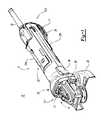
- FIG. 1is a perspective view of a handheld grinder
- FIGS. 2A and 2Bare side views of the handheld grinder with a bottom handle cover attached and removed, respectively;
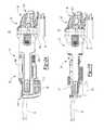
- FIG. 3is a cross-sectional side view of an example embodiment of the handheld grinder
- FIGS. 4A and 4Bare schematics of an example motor control system for the handheld grinder
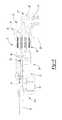
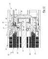
- FIG. 5is a perspective exploded view of the example embodiment of the handheld grinder
- FIG. 6is an axial view of the motor case in the example embodiment of the grinder without the motor therein;
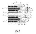
- FIG. 7is a partial cross-sectional view of the motor case in the example embodiment of the handheld grinder.
- FIG. 8is a partial perspective view of motor case with slot configured to receive positional sensor board
- FIG. 9is a partial perspective view of the motor case with an overmolded positional sensor board
- FIG. 10is a perspective view of the overmolded positional sensor board
- FIG. 11is a partial perspective cross-sectional view of the motor case with the overmolded positional sensor board
- FIG. 12is a partial cross-sectional view of the motor case in an alternative example embodiment of the handheld grinder.
- FIGS. 13A and 13Bare perspective exploded views of the alternative example embodiment of the handheld grinder
- FIG. 14is a perspective exploded view of an alternative embodiment of a motor case for use in the handheld grinder.
- FIGS. 15A and 15Bare partial perspective views of the alternative embodiment of the motor case in exploded and assembled form, respectively;
- FIG. 16is a partial perspective view of another alternative embodiment of a motor case in assembled form
- FIG. 17is a perspective exploded view of yet another alternative embodiment of a motor case for use in the handheld grinder.
- FIG. 18is a perspective assembled view of the motor case in FIG. 17 with enclosure member removed;
- FIG. 19is a perspective assembled view of the motor case in FIG. 18 with an additional positional sensor board;
- FIGS. 20A and 20Bare isometric views of a control side and a power side, respectively, of a power control module in the example embodiment of the handheld grinder;
- FIG. 21is a side view of the power control module
- FIGS. 22A and 22Bare perspective exploded views of the power control module in normal and upside down orientations, respectively;
- FIG. 23is a front view of the power control module
- FIGS. 24A and 24Bare isometric views of the power control module with casing removed.
- FIGS. 25A and 25Bare side views of the control circuit board and the power circuit board in an unfolded and a folded arrangement, respectively.
- the power tool 10includes an elongated housing 12 , a motor 16 ( FIG. 3 ), a module casing or power module support structure 18 ( FIG. 3 ), and a planar circuit board 20 ( FIG. 3 ).
- the housing 12defines a cavity 21 ( FIG. 3 ) and includes a motor case 22 and a handle portion 23 .
- the motor case 22is positioned at one end 12 - 1 of the housing 12 and includes a gear case 24 and a power switch 26 .
- the gear case 24includes a gearset 26 , an output shaft 27 , and a threaded opening 28 .
- the gearset 26is positioned within the gear case 24 and is drivably coupled to the motor 16 .
- the output shaft 27is drivably connected to the gearset 26 within the gear case 24 and extends perpendicular to the longitudinal axis of the housing 12 .
- the output shaft 27is also coupled to a grinding or a cutting disc (not shown) via a flange (not shown).
- the grinding diskmay be removed and replaced with a new grinding disk.
- a user of the power tool 10may replace the existing grinding disk with a new grinding disk after the existing disk wears out.
- An adjustable guard 29may cover at least a portion of the rotating disk to obstruct sparks and debris generated during operation of the power tool 10 .
- the threaded opening 28allows for selectively attaching a side-handle (not shown) to enable two-handed operation.
- the power switch 26is positioned on a side of the motor case 22 and allows for the user to turn the power tool 10 ON and OFF.
- the handle portion 23extends axially from the motor case 22 toward a second end 12 - 2 of the housing 12 and includes a first cover 23 a and a second cover 23 b .
- the first and the second covers 23 a , 23 bare secured together around the module casing 18 and the planar circuit board 20 disposed within the cavity 21 of the handle portion 23 .
- the second cover 23 bincludes a support member 30 protruding outwardly therefrom and positioned at the second end 12 - 2 of the housing 12 .
- the support member 30includes openings 31 extending therethrough to allow incoming air to enter the cavity 21 .
- An AC power cord 32is attached to the handle portion 23 at the second end 12 - 2 of the housing 12 to supply electric power to the power tool 10 .
- the power tool 10may include a chuck that is configured to receive a drill bit or a screw bit, thereby allowing the power tool 10 to be used as a power drill or a power screw driver.
- FIG. 4Adepicts a schematic that illustrates an example of a motor drive circuit 33 .
- the motor drive circuit 33is comprised generally of a controller 34 , a switching arrangement 36 , a driver circuit 38 , a rectifier 40 , a DC bus capacitor 42 , a power supply 44 , and an auxiliary switch path 46 .
- the motor drive circuit 33may further include positioned sensors 48 , such as Hall Effect sensors that are configured to detect rotational motion of the motor 16 and generate a signal indicative of the rotational motion.
- the signalmay have a periodic waveform whose magnitude may vary in accordance with the rotational position of the motor 16 . It should be noted, that other types of positional sensors may be alternatively utilized and should not be limited to Hall Effect sensors.
- An AC supply 52delivers an alternating current to the rectifier 40 through, for example, the power cord 32 .
- the rectifier 40converts the alternating current into a direct current that is outputted to a DC bus 54 (i.e., power line/bus).
- the output of the rectifier 40may be pulsating DC signal and not a pure DC signal.
- the DC bus capacitor 42is electrically connected in parallel with the rectifier 40 .
- the switching arrangement 36is electrically connected with the DC bus capacitor 42 and may receive the pure DC signal or the substantially pure DC signal from the DC bus capacitor 42 via the DC bus 54 .
- the switching arrangement 36includes a plurality of motor switches 55 that, when switched on, deliver the DC current to the motor 16 .
- the motor switches 55may be IGBTs or FETs, for example.
- the switching arrangement 36may be further defined as a three-phase inverter bridge although other arrangements are contemplated by this disclosure.
- the driver circuit 38interfaces with the motor switches 55 of the switching arrangement 36 .
- the driver circuit 38controls the state of the motor switches 55 .
- the driver circuit 38is shown as being separate from the switching arrangement 36 .
- the driver circuit 38 and the switching arrangement 36may be a single integrated circuit which may be commercially available from various manufacturers.
- the switching arrangement 36which may include IGBTs, and the driver circuit 38 may be a part of an integrated power module.
- the controller 34interfaces with the driver circuit 38 and may generate PWM signals to control the motor 16 .
- the controller 34receives power from the power supply regulator 44 .
- the controller 34may receive power directly from the rectifier 40 .
- the power supply regulator 44is electrically connected in parallel with the rectifier 40 and operates to power the driver circuit 38 via the power on/off switch 26 .
- the power on/off switch 26is positioned between the power supply regulator 44 and the driver circuit 38 .
- the driver circuit 38When the power on/off switch 26 is switched to the ON-position, the driver circuit 38 receives power from the power supply regulator 44 . When the driver circuit 38 receives power, the driver circuit 38 is able to control the state of the motor switches 55 and the motor 16 is on.
- the driver circuit 38does not receive power from the power supply regulator 44 .
- the driver circuit 38is not able to control the state of the motor switches 55 and the electric motor is off.
- the power on/off switch 26is electrically connected between the rectifier 40 and the driver circuit 38 .
- the power on/off switch 26is positioned such that the power from the AC power supply 52 does not pass through the power on/off switch 26 .
- the current being drawn by the motor 16does not pass through the power on/off switch 26 .
- the current passing through the power on/off switch 26is the current being drawn by the driver circuit 38 and the current being drawn by the driver circuit 38 is lower than the current being drawn by the electric motor 16 .
- the DC bus capacitor 42may be a link capacitor having relatively small capacitance and does not act to smoothen the full-wave rectified AC voltage.
- the DC bus capacitor 42is a bypass capacitor that removes the high frequency noise from the bus voltage.
- the auxiliary switch path 46is electrically coupled in parallel with the rectifier 40 and the link capacitor 42 , and is electrically connected between the rectifier 40 and the switching arrangement 36 .
- the auxiliary switch path 46includes an auxiliary capacitor 56 and a switch 58 positioned in series with the auxiliary capacitor 56 .
- the switch 58may be a controlled switch, such as a MOSFET or an IGBT, in an embodiment.
- the switch 58may be controlled by software programmed into the controller 34 or another programmable microcontroller. Alternatively, the switch 58 may be controlled by hardware, such as a switch control circuit 60 , described in detail below.
- the switch 58When the switch 58 is closed, the auxiliary capacitor 56 is connected parallel to the DC bus capacitor 42 .
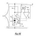
- FIG. 4Bdepicts an example embodiment of the auxiliary switch path 46 and the switch control circuit 60 .
- the switch control circuit 60selectively activates or deactivates the auxiliary capacitor 56 .
- the switch 58is provided as a transistor 62 , such as an insulated-gate bipolar transistor (IGBT) that has an anti-parallel diode 64 .
- the diode 64is configured to form a charge path (i.e., a first path) indicated by arrow 66 and the IGBT 62 is configured to form a discharge path (i.e., second path) indicated by arrow 67 .
- the switch 58controls the flow of current through the auxiliary capacitor 56 via the charge path or the discharge path. It is readily understood that other switching mechanisms may be utilized and that the switch 58 should not be limited to the components described herein.
- the switch control circuit 60includes a sensing circuit 68 and a comparator 69 .
- the sensing circuit 68senses voltage along the DC bus 54 .
- the sensing circuit 68detects the voltage across the auxiliary capacitor 56 .
- the sensing circuit 68may alternatively be arranged to sense the voltage difference between the positive and negative nodes of the DC bus 54 (denoted as +DC and ⁇ DC herein).
- the sensing circuit 68provides the sensed voltage to the comparator 69 , which compares the voltage to a predetermined voltage threshold V clamp . If the sensed voltage exceeds the voltage threshold V clamp , the comparator 69 output turns ON the transistor 62 , which couples the auxiliary capacitor 56 to the DC bus 54 and discharges the auxiliary capacitor 56 . More particularly, the IGBT 62 allows current to follow through the discharge path 67 and the auxiliary capacitor 56 discharges built up charge to reduce the bus voltage transients.
- the IGBT 62When the sensed voltage is lower than the voltage threshold, the IGBT 62 is turned OFF and current flows through the diode 64 via the charge path 66 .
- the auxiliary capacitor 56is charged by current through the anti-parallel diode 64 during every peak of every half cycle of the bus voltage when the bus voltage exceeds the voltage of the auxiliary capacitor 56 . This keeps the auxiliary capacitor 56 in fully charged state.
- Current to the auxiliary capacitor 56 during normal operationis very nominal and may be determined by the sum of capacitor's internal discharge and the current through the sensing circuit 68 . The current is small enough that it does not influence Power-Factor or harmonics of the system.
- the voltage threshold for opening and closing the switch 58may be provided as two separate thresholds for creating suitable hysteresis.
- a first voltage thresholdmay be designated for having the switch 58 open when the detected voltage is less than the first voltage threshold and a second voltage threshold may be designated for closing the switch 58 when the detected voltage is greater than or equal to the second voltage threshold.
- the second voltage thresholdis greater than the first voltage threshold.
- the motor 16is mounted within the cavity 21 of the motor case 22 .
- the motor 16is also drivably coupled to the output shaft 27 ( FIG. 3 ) of the gear case 24 .
- the motor 16is a three-phase brushless DC (BLDC) motor and includes a stator assembly 70 , a rotor assembly 72 , and a baffle 73 ( FIG. 5 ).
- the stator assembly 70includes a cylindrical lamination stack 74 configured to receive a portion of the rotor assembly 72 .
- the cylindrical lamination stack 74further includes windings 76 wound and connected in either a wye or a delta configuration around the rotor assembly 72 to define the three phases of the motor 16 .
- the rotor assembly 72includes a rotor shaft 78 , a cylindrical rotor lamination stack 80 ( FIG. 7 ), a rear bearing 82 , a sensing magnet 84 , and a fan 86 ( FIG. 5 ).
- the rotor shaft 78is drivably coupled to the output shaft 27 ( FIG. 3 ) and extends longitudinally through the motor case 22 of the housing 12 .
- the rotor lamination stack 80is rotatably mounted on the rotor shaft 78 .
- the rotor lamination stack 80may include a series of flat laminations (not shown) attached together via an interlock (e.g., snap-fitted, adhesive, overmold) that houses or hold two or more permanent magnets (not shown) therein.
- the rear bearing 82is mounted on a rear end 87 of the rotor shaft 78 to support the shaft 78 within the power tool 10 .
- the sensing magnet 84is rotatably mounted on the rear end 87 of the rotor shaft 78 behind the rear bearing 82 .
- the fan 86is rotatably mounted on a front end 88 of the rotor shaft 78 .
- the fan 86 of the rotor assembly 72includes blades 89 that rotate with the shaft 78 to facilitate the incoming air entering the openings 31 to flow through the motor 16 .
- the baffle 73 disposed between the stator assembly 70 and the fan 86guides the air flowing through the housing 12 towards exhaust vents 92 ( FIG. 1 ) of the gear case 24 .
- a partition member or wall 94separates the cavity 21 ( FIG. 3 ) of the housing 12 between the motor case 22 and the handle portion 23 .
- the partition member 94may be integrally formed with the housing 12 and extend perpendicular relative to the longitudinal axis of the housing 12 .
- the partition member 94includes at least one aperture 95 at a periphery thereof to permit air flow between the motor case 22 and the handle portion 23 .
- the partition member 94also includes first and second axial walls 96 , 97 extending perpendicular therefrom.
- the partition member 94 and the first and second walls 96 , 97cooperate to form a cylindrically-shaped pocket 98 .
- the second wall 97having a radially extending slot 100 (i.e., perpendicular to the longitudinal axis of the rotor shaft 78 ) that extends therethrough such that the pocket 98 is accessible through the slot 100 .
- a flange 102extends perpendicular from terminal ends of the walls 96 , 97 toward the rotor shaft 78 to define an opening 104 in the pocket 98 .
- the opening 104 of the pocketfaces the gear case 24 ( FIG. 1 ) at the one end 12 - 1 of the housing 12 .
- a substantially rectangular-shaped shroud member 106 defining an opening 108extends perpendicular from the second wall 97 ( FIG. 11 ) of the pocket 98 .
- the shroud member 106extends overtop the slot 100 .
- the shroud member 106is also positioned on the second wall 97 between fastener-receiving apertures 114 of the second cover 23 b .
- a back wall 111 of the shroud member 106is co-planar with the partition member 94 and defines a U-shaped cut-out 112 . It is understood that the shroud member 106 may also be trapezoidal or semi-circular.
- a substantially rectangular-shaped positional sensor board 116for detecting a rotational position of the rotor assembly 72 includes, a top member 118 and wires 119 . It should be understood that although this example embodiment includes the positional sensor board 116 being substantially rectangular, other shapes (e.g., trapezoidal, or rectangular with a curved surface) are within the scope of the present disclosure.
- the positional sensor board 116includes an aperture 117 that partially receives the shaft 78 therein.
- the top member 118may be a polymeric material that is attached to the positional sensor board 116 by an overmolding process.
- the wires 119 carrying positional signals from the sensors of the positional sensor board 116extend toward the second end 12 - 2 of the housing 12 .
- the positional sensor board 116may be radially inserted (i.e., inserted in a direction perpendicular to the rotational axis of the shaft 78 ) within the slot 100 by the user such that a portion of the board 116 including the sensors extends into the pocket 98 and face the sensing magnet 84 . Once fully inserted, the wires 119 are comfortably received in the cut-out 112 of the back wall 111 .
- the top member 118 of the positional sensor board 116fluidly seals the opening 108 and the cut-out 112 of the shroud member 106 to prevent dust and debris from entering into the opening 124 and damaging the positional sensor board 116 and the sensing magnet 84 .
- a sealing member 120( FIG. 11 ) is disposed around the rear bearing 82 to sealingly block contamination (e.g., dust, debris, fluids) from reaching and damaging the sensing magnet 84 and the positional sensor board 116 within the pocket 98 .
- FIGS. 12, 13A, and 13Banother power tool 208 is provided.
- the structure and function of the housing 212may be similar to that of the housing 12 , apart from any exceptions described below.
- This embodimentincludes an alternate housing 212 having a different sealing technique than the housing 12 .
- a motor 216is mounted within a motor case 222 in a similar manner described above, apart from any exceptions described below.
- the motor 216is drivably coupled to the output shaft (not shown) of the gear case 224 .
- the motor 216includes a stator assembly 270 , a rotor assembly 272 , and a baffle (not shown).
- the stator assembly 270includes a cylindrical lamination stack 274 configured to receive a portion of the rotor assembly 272 .
- the rotor assembly 272includes a rotor shaft 278 , a cylindrical rotor lamination stack 280 , a rear bearing 282 , a sensing magnet 284 , and a fan (not shown).
- the rotor shaft 278is extends longitudinally through the motor case 222 of the housing 212 .
- the rotor lamination stack 280is rotatably mounted on the rotor shaft 278 .
- the rotor lamination stack 280may include a series of flat laminations (not shown) attached together via an interlock (e.g., press fit, adhesive, overmold) that houses or hold two or more permanent magnets (not shown) therein.
- the rear bearing 282is mounted on a rear end 287 of the rotor shaft 278 to support the shaft 278 within the power tool 10 .
- the sensing magnet 284is rotatably mounted on the rear end 287 of the rotor shaft 278 in front of the rear bearing 282 .
- a partition member or wall 294separates the cavity (not shown) of the housing 212 between the motor case 222 and a handle portion 223 .
- the partition member 294may be integrally formed with the housing 212 and extend perpendicular relative to the longitudinal axis of the rotor shaft 278 .
- the partition member 294includes at least one aperture (not shown) at a periphery thereof to permit air flow between the motor case 222 and the handle portion 223 .
- the partition member 294also includes first and second axial walls 296 , 297 extending perpendicular therefrom. The partition member 294 and the first and second walls 296 , 297 cooperate to form a cylindrically-shaped pocket 298 .
- a flange 202extends perpendicular from terminal ends of the walls 296 , 297 toward the rotor shaft 278 to define an opening 260 in the pocket 298 .
- the pocket 298receives the rotor shaft 278 and the rear bearing 282 of the rotor assembly 272 .
- the partition member 294supports the rear bearing 282 in the pocket 298 .
- a seal member 250is positioned between the flange 202 and the shaft 278 in the opening 260 .
- the sensing magnet 284is disposed adjacent to the pocket 298 .
- the slot 210is positioned between the pocket 298 and the sensing magnet 284 .
- the sensing magnet 284is positioned between the slot 210 and the rotor lamination stack 280 .
- a positional sensor board 217includes sensors 203 on a first side 213 and a connector 205 extending perpendicular from a second side 207 ( FIG. 12 ).
- a substantially rectangular-shaped shroud member 206extends perpendicular from a surface 209 overtop the slot 210 .
- a first cover 223 a of the handle portion 23includes a compartment 211 and a protrusion 215 .
- the compartment 211has a similar profile as the shroud member 206 overtop the slot 210 and extends perpendicular from a surface 214 of the first cover 223 a .
- the first cover 223 amay also define recess channels 218 surrounding the compartment 211 .
- the channels 218may include a strip of flexible polymeric material (e.g., rubber) disposed therein.
- the protrusion 215is positioned within the compartment 211 and projects perpendicularly from the surface 214 of the first cover 223 a toward the shroud member 206 .
- the userinserts the positional sensor board 217 within the slot 210 .
- the first cover 223 a and the second cover 223 bare securely fastened to each other via fasteners 221 , thereby intimately mating the compartment 211 with the shroud member 206 .
- the protrusion 215 of the first cover 223 aabuts ( FIG. 13 ) the positional sensor board 217 to retain the positional sensor board 217 securely within the slot 210 .
- the recess channels 218receive walls 225 of the shroud member 206 to further prevent contamination (e.g., debris, dust, fluids, etc.
- the structure and function of the motor case 322may be similar or identical to that of the motor cases 22 , 222 , apart from any exceptions described below.
- This embodimentincludes an alternate motor case 322 having an alternative sensor board installation and sealing technique than the motor cases 22 , 222 .
- the motor case 322may house the motor 216 having the structure and function as described above.
- the motor case 322may be a separate component that can be threadably attached to handle portion (not shown) as opposed to integrally formed thereto.
- the motor case 322includes a partition member or wall 314 at a rear end 318 .
- the partition member 314includes at least one aperture 317 at a periphery thereof.
- the partition member 314separates the motor case 322 and the handle portion (not shown) in the cavity (not shown).
- the motor case 322also having a pocket 320 and a channel 323 formed at the rear end 318 .
- the pocket 320is positioned between the channel 323 and a back wall 326 and further defines a slot 324 .
- the back wall 326includes a pair of slots 328 .
- the channel 323is formed at the rear end 318 between a pair apertures 330 .
- a top member 332includes a pair of elongated legs 334 , a pair of protrusions 336 , and a U-shaped opening 338 .
- the pair of protrusions 336are positioned towards a front end of the top member 332 .
- the opening 338is positioned between the pair of elongated legs 334 at a rear end.
- a positional sensor board 300within the slot 324 of the motor case 322 will be described in detail.
- the useroperatively connects the connector 306 of the positional sensor board 300 with a connector 342 of a wire assembly 344 .
- the userthen inserts the positional sensor board 300 in the slot 324 of the pocket 320 .
- the pair of elongated legs 334 and the pair of protrusions 336 of the top member 332are received in the pair of apertures 330 and the pair of slots 328 , respectively, to secure the top member 332 to the rear end 318 of the motor case 322 .
- the top member 332covers the connectors 306 , 342 and the positional sensor board 300 within the channel 323 and the pocket 320 , respectively, while allowing a portion of wires 348 of the wire assembly 344 to extend out the U-shaped opening 338 .
- the top member 332retains the positional sensor board 300 in place and protects the sensor board 300 from contamination (e.g., debris, fluids, etc.).
- top member 432may be similar or identical to that of the top member 332 , apart from any exceptions described below.
- This embodimentincludes an alternate U-shaped top member 432 having a different sealing technique than the top member 332 .
- the U-shaped top member 432includes a pair of legs 434 and a main body 436 .
- Each leg 434includes an aperture (not shown) and is integrally formed to an end of the main body 436 such that a gap 440 is defined between the legs 434 .
- the useroperatively connects the connector 306 of the positional sensor board 300 with the connector 342 of the wire assembly 344 .
- the userthen inserts the positional sensor board 300 within the slot 324 .
- the top member 432is then secured to the rear end 318 of the motor case 322 by fasteners 442 that are received in the apertures (not shown) of the legs 434 and the apertures 330 at the rear end 318 .
- the main body 436 of the top member 432covers and retains the positional sensor board 300 in place while the connectors 306 , 342 are received in the channel 323 .
- the top member 432also covers additional gaps around the connectors 306 , 342 and the positional sensor board 300 to block or reduce the amount of contamination (e.g., debris, dust, fluids) in the area.
- the structure and function of the motor case 522may be similar or identical to that of the motor cases 22 , 222 , 322 , apart from any exceptions described below.
- This embodimentincludes an alternate motor case 522 having an alternative sensor board installation and sealing technique than the motor cases 22 , 222 , 322 .
- the motor case 522may be a separate component that can be threadably attached to handle portion (not shown) as opposed to integrally formed thereto.
- the motor case 522mounts a motor (not shown) within, which includes a rotor shaft 578 extending longitudinally through the motor case 522 .
- the motor case 522includes a partition member or wall 514 and a rectangular shaped shroud member 520 at a rear end 518 .
- the partition member 514includes a plurality of first apertures 516 at a periphery thereof to permit airflow through the motor case 522 and the handle portion in the cavity (not shown).
- the partition member 514also separates the motor case 522 and the handle portion within the cavity.
- the shroud member 520is attached to the partition member 514 at the rear end 518 of the motor case 522 .
- the rotor shaft 578 of the rotor assemblyextends through a second aperture (not shown) in the partition wall 514 and into the shroud member 520 attached to the rear end 518 .
- the shroud member 520includes at least one post 530 therein.
- a diametrical sensing magnet 584includes an outer surface 590 and a flange 591 .
- the flange 591protrudes outwardly from the outer surface 590 of the sensing magnet 584 .
- the flange 591includes a sloped surface 592 .
- the sensing magnet 584is mounted onto an end of the rotor shaft 578 that extends into the shroud member 520 .
- a nut 582secures the sensing magnet 584 onto the rotor shaft 578 .
- the sensing magnet 584may also be mounted to the end portion of the rotor shaft 578 prior to the shaft 578 extending through the motor case 522 . That is, the partition member 514 at the rear end 518 of the motor case 522 may include the second aperture large enough to permit the sensing magnet 584 and the rotor shaft 578 to extend through the motor case 522 . This removes the step of having to mount the sensing magnet 584 to the rotor shaft 578 at the rear end 518 after the shaft 578 extends into the shroud member 520 .
- a substantially rectangular-shaped positional sensor board 500includes a first end 593 and a second 594 .
- the first end 593includes a connector case 596 .
- the second end 594having a semi-circular profile formed in the sensor board 500 .
- the userinserts the positional sensor board 500 inside the shroud member 520 such that the second end 594 is disposed on the surface 592 of the flange 591 of the sensing magnet 584 .
- the connector case 596 at the first end 593is electrically connected to a connector piece (not shown) of the shroud member 520 . This secures the positional sensor board 500 within the shroud member 520 ( FIG. 19 ).
- the plurality of posts 530further support the sensor board 500 within the shroud member 520 .
- a rectangular-shaped top member 532form-fittingly covers and fluidly seals the shroud member 520 , thereby protecting the positional sensor board 500 against contamination (e.g., debris, dust, fluids) once connected within the shroud member 520 .
- contaminatione.g., debris, dust, fluids
- FIG. 19another alternate embodiment is provided.
- the structure and function of the shroud member 620may be similar or identical to that of the shroud member 520 , apart from any exceptions described below.
- This embodimentincludes an alternate shroud member 620 having a different sealing technique than the shroud member 520 .
- the shroud member 620is attached to the partition member 514 at the rear end 518 of the motor case 522 .
- the shroud member 620includes at least one post 630 therein.
- a positional sensor board 600has a substantially similar profile as the shroud member 620 and includes a pair of apertures (not shown) positioned at an end 638 of the positional sensor board 600 .
- Fasteners 646are received in the pair of apertures in the positional sensor board 600 and a corresponding pair of apertures (not shown) in the shroud member 620 to secure the positional sensor board 600 to the shroud member 620 .
- the positional sensor board 600is supported against the at least one post 630 within the shroud member 620 and is self-sealed to prevent contamination (e.g., debris, dust, fluids).
- the rectangular module casing 18is provided.
- the module casing 18is disposed entirely within the cavity 21 ( FIG. 3 ) of the handle portion 23 of the housing 12 .
- the module casing 18defines a first end 18 - 1 and a second end 18 - 2 .
- the first end 18 - 1is positioned adjacent to the motor case 22 ( FIG. 3 ) of the housing 12 and the second end 18 - 2 of the module casing 18 extends toward the second end 12 - 2 of the housing 12 .
- the casing 18also includes a first surface 130 , a U-shaped second surface 132 , sides 134 , 135 , and a clip 136 .
- the first surface 130extends parallel to the longitudinal axis of the housing 12 ( FIG. 3 ) and divides the casing 18 between an upper portion and a lower portion.
- the second surface 132extends perpendicular from the first surface 132 at the upper portion and forms a cavity 138 having an opening 140 ( FIG. 22A ).
- the sides 134 , 135extend perpendicular from the first surface 130 toward the lower portion of the casing 18 .
- Flanges 142 , 143extend from the sides 134 , 135 , respectively, toward each other at the first end 18 - 1 of the casing 18 to define an opening 144 at the lower portion.
- the clip 136is attached to the casing 18 at the second end 18 - 2 and extends outwardly therefrom.
- a first L-shaped heat sink 147 - 1 and a second L-shaped heat sink 147 - 2are attached to the bottom portion of the casing 18 by tabs 148 .
- the heat sinks 147 - 1 , 147 - 2are attached to the casing 18 such that the heat sinks 147 - 1 , 147 - 2 abut each other to form a U-shape cavity 149 ( FIG. 23 ).
- the planar circuit board 20is attached to the module casing 18 by fasteners 152 that are attached at the second end 18 - 2 thereof.
- the planar circuit board 20also extends axially along the longitudinal axis of the housing 12 ( FIG. 3 ).
- the planar circuit board 20divides the cavity 21 ( FIG. 3 ) of the handle portion 23 between an upper portion and a lower portion.
- the planar circuit board 20includes a first board or top segment board 150 and a second board or bottom segment board 151 .
- the first and second boards 150 , 151are interconnected by a hinge section 153 that allow for electrical communication therebetween such that the first board 150 is folded over top of the second board 151 and the first board 150 is affixed to a top surface of the casing 18 and the second board is affixed to a bottom surface of the casing 18 .
- the hinge section 153is covered and protected by a cover member 154 positioned at the first end 18 - 1 of the casing 18 .
- the first board 150is received in the cavity 138 at the upper portion of the casing 18 via the opening 140 and the second board 151 is positioned at the lower portion of the casing 18 .
- the planar circuit board 20includes a dial assembly 155 , the rectifier 40 , the DC bus capacitors 42 , the motor switches 55 , and the auxiliary capacitor 56 .
- the dial assembly 155is attached to the first board 150 of the planar circuit board 20 at the second end 18 - 2 of the module casing 18 .
- the dial assembly 155includes a dial 156 , a seal 157 , a frame 158 and fasteners 159 .
- the dial 156is attached to the frame 158 .
- the dial 156may be a potentiometer, for example, that permits the adjusting of current flow through the planar circuit board 20 .
- the seal 157is positioned between the dial 156 and the frame 158 .
- the frame 158is attached to the first board 150 by the fasteners 159 .
- the rectifier 40is soldered to a bottom surface 160 of the second board 151 between the auxiliary capacitor 56 and the heat sinks 147 - 1 , 147 - 2 .
- a cover 162is attached to the rectifier 40 by a fastener 164 that extends through apertures 171 , 172 of the cover 162 and the rectifier 40 , receptively.
- the cover 162separates the rectifier 40 from contacting the auxiliary capacitor 56 .
- a nut 166further secures the fastener 164 , the cover 162 , and the rectifier 40 together.
- the DC bus capacitors 42are soldered on the bottom surface 160 of the second board 151 in the U-shaped cavity 149 formed by the heat sinks 147 - 1 , 147 - 2 .
- the motor switches 55include a first set containing three adjacently oriented switches 168 and a second set containing three adjacently oriented switches 170 .
- the first set of switches 168are soldered to the bottom surface 160 of the second board 151 between the heat sink 147 - 1 and the DC bus capacitors 42 .
- the second set of switches 170are soldered to the bottom surface 160 of the second board 151 between the heat sink 147 - 2 and the DC bus capacitors 42 .
- a first plate 172 - 1is positioned between the first set of switches 168 and the heat sink 147 - 1 and a second plate 172 - 2 is positioned between the second set of switches 170 and the heat sink 147 - 2 .
- the first and second plates 172 - 1 , 172 - 2permit heat to flow therethrough to the heat sinks 147 - 1 , 147 - 2 , respectively, while preventing electricity therethrough.
- a first shielding member 174 - 1is positioned between the DC bus capacitors 42 and the first set of switches 168 and a second shielding member 174 - 2 is positioned between the bus capacitors 42 and the second set of switches 170 .
- a first set of fasteners 176are securely received in apertures 178 , 180 , 182 , and 184 of the first shielding member 174 - 1 , the first set of switches 168 , the first plate 172 - 1 , and the heat sink 147 - 1 , respectively.
- a second set of fasteners 186are securely received in apertures 188 , 190 , 192 , and 194 of the second shielding member 174 - 2 , the set set of switches 170 , the second plate 172 - 2 , and the heat sink 147 - 2 , respectively.
- the auxiliary capacitor 56is soldered to the bottom surface 160 of the second board 151 .
- the capacitor housing 181is also attached to the clip 136 at the second end 18 - 2 of the casing 18 , so that the capacitor 56 is supported within the support member 30 of the second cover 23 b ( FIG. 2 ).
- the capacitor 56is adjacent to the openings 31 ( FIG. 2 ) of the support member 30 to benefit from the entering airflow therethrough.
- the electrical componentse.g., capacitors 42 , 56 , motor switches 55 , rectifier 40
- the heat sinks 147 - 1 , 147 - 2transfer the heat generated by the electrical components to the airflow passing through the area.
- the placement of the auxiliary capacitor 56 in the support member 30( FIG. 2 ) further allows for the incoming air entering through the openings 31 to cool the auxiliary capacitor 56 .
- the planar circuit board 20may be in folded or unfolded positions.
- first, second, third, etc.may be used herein to describe various elements, components, regions, layers and/or sections, these elements, components, regions, layers and/or sections should not be limited by these terms. These terms may be only used to distinguish one element, component, region, layer or section from another region, layer or section. Terms such as “first,” “second,” and other numerical terms when used herein do not imply a sequence or order unless clearly indicated by the context. Thus, a first element, component, region, layer or section discussed below could be termed a second element, component, region, layer or section without departing from the teachings of the example embodiments.
- Spatially relative termssuch as “inner,” “outer,” “beneath,” “below,” “lower,” “above,” “upper,” and the like, may be used herein for ease of description to describe one element or feature's relationship to another element(s) or feature(s) as illustrated in the figures. Spatially relative terms may be intended to encompass different orientations of the device in use or operation in addition to the orientation depicted in the figures. For example, if the device in the figures is turned over, elements described as “below” or “beneath” other elements or features would then be oriented “above” the other elements or features. Thus, the example term “below” can encompass both an orientation of above and below. The device may be otherwise oriented (rotated 90 degrees or at other orientations) and the spatially relative descriptors used herein interpreted accordingly.
Landscapes
- Engineering & Computer Science (AREA)
- Mechanical Engineering (AREA)
- Power Engineering (AREA)
- Microelectronics & Electronic Packaging (AREA)
Abstract
Description
This application claims the benefit of U.S. Provisional Application Nos. 62/241,385 filed on Oct. 14, 2015, and 62/249,528 filed on Nov. 2, 2015, and 62/322,462 filed on Apr. 14, 2016. The entire disclosures of the above applications are incorporated herein by reference.
The present disclosure relates to various features of a handheld grinder or similar power tool having a brushless electric motor.
Some power tools include brushless electric motors. Power tools with brushless electric motors are used for woodworking and metalworking, for example. The environments that power tools are used in contain various contaminants (e.g., dust, debris, fluids). These contaminants compromise various components of the power tool, which undesirably impacts the function, durability, and reliability of the power tool.
Additionally, most power tools include several circuit boards that reside inside a housing of the power tool. The circuit boards are used to support the capacitor, the power switch and circuitry that is used for controlling the brushless motor. These components undesirably increase the heat generation of the power tool during the operation thereof.
Therefore, there is a need for a power tool that protects components from contamination in such working environments while generating less heat, thereby improving the function, durability, and reliability of the power tool.
This section provides background information related to the present disclosure and is not necessarily prior art.
This section provides a general summary of the disclosure, and is not a comprehensive disclosure of its full scope or all of its features.
In one form, a handheld grinder includes an elongated housing, an electric motor, an output shaft, a wall, a planar circuit board, and a motor drive circuit. The elongated housing defines a cavity therein that includes a motor case disposed at a front end thereof and a handle portion extending axially along a longitudinal axis of the housing from the motor case to a rear end of the housing. The electric motor has a drive shaft and is mounted within the motor case. The output shaft is drivably coupled to the drive shaft of the electric motor and extends perpendicular to the drive shaft. The wall separates the cavity between the motor case and the handle portion of the housing and is configured to support a rear bearing for the drive shaft of the electric motor and includes one or more holes which permit air flow between the motor case and the handle portion of the housing. The planar circuit board is disposed in the handle portion of the housing and extends axially along the longitudinal axis of the housing. The planar circuit board divides the handle portion into an upper section and a lower section. The motor drive circuit is accommodated entirely within the handle portion of the housing on the planar circuit board and configured to deliver a direct current from a DC power bus to the electric motor. The motor drive circuit includes a link capacitor and an auxiliary capacitor. The link capacitor is mounted on the planar circuit board and is coupled across the DC power bus. The auxiliary capacitor has a capacitance more than the capacitance of the link capacitor and is electrically coupled across the DC power bus. The auxiliary capacitor is mounted in the lower section of the handle portion and at the rear end of the handle portion of the housing.
In some configurations, the wall includes a pocket defining an open end and a closed end, wherein the open end of the pocket faces front end of the housing and is sized to receive the rear bearing.
In some configurations, the handheld grinder includes one or more sense magnets affixed to the drive shaft, where the one or more sense magnets are arranged along the drive shaft in between the rear bearing and the closed end of the pocket.
In some configurations, the handheld grinder includes one or more position sensors mounted to a position sense board, where the position sensors cooperate with the one or more sense magnets to sense rotational motion of the drive shaft. A slot is formed in the pocket and configured to receive the position sense board therein such that the position sense board is arranged adjacent to the one or more sense magnets.
In some configurations, the slot in the pocket is overmolded and thereby fluidly seals the position sense board in the pocket.
In some configurations, the motor drive circuit further includes a rectifier, a switching arrangement, an auxiliary switch path, and a switch control circuit. The rectifier is configured to receive an alternating current from an alternating current (AC) power source and operable to convert the alternating current to a direct current supplied to the DC power bus. The switching arrangement has a plurality of motor switches connected electrically between the rectifier and the electric motor, and operates to deliver the direct current from the rectifier to the electric motor. The auxiliary switch path is electrically coupled in parallel with the rectifier and electrically connected between the rectifier and the switching arrangement. The auxiliary switch path includes a switch in series with the auxiliary capacitor. The switch control circuit is configured to detect voltage of the DC power bus and to control state of the switch in accordance with magnitude of the detected voltage, such that state of the switch creates either a charging path for the auxiliary capacitor or a discharging path for the auxiliary capacitor.
In some configurations, the handheld grinder includes a power module support structure disposed in the handle portion of the housing and extending axially along the longitudinal axis of the housing. The circuit board includes a top board segment integrally interconnected by a hinge section to a bottom board segment, such that the top board segment is folded over top of the bottom board segment and the top board segment is affixed to a top surface of the power module support structure and the bottom board segment is affixed to a bottom surface of the power module support structure.
In some configurations, the plurality of motor switches are mounted along two lateral side surfaces of the power module support structure and further includes a heat sink mounted to each of the two lateral side surfaces of the power module support structure, such that the heat sink is adjacent and thermally coupled to the plurality of motor switches.
In some configurations, a speed dial is mounted to the top board segment of the circuit board and operable to set rotational speed of the electric motor.
In some configurations, a support member protruding outwardly from the housing at the rear end thereof.
In some configurations, the support member includes openings extending therethrough to allow air to enter into the cavity.
In yet another form, the power tool includes a housing, an electric motor, and a motor drive circuit. The housing defines a cavity therein, where the cavity is divided into a motor case and a handle portion extending axially along a longitudinal axis from the motor case towards an axial end. The electric motor has a drive shaft and mounted within the motor case. The motor drive circuit is accommodated entirely within the handle portion of the housing and configured to drive the electric motor. The motor drive circuit includes a rectifier, a switching arrangement, a link capacitor and an auxiliary capacitor. The rectifier is configured to receive an alternating current from an alternating current (AC) power source and operable to convert the alternating current to a direct current supplied to a DC power bus. The switching arrangement has a plurality of motor switches connected electrically between the rectifier and the electric motor, and operates to deliver the direct current from the rectifier to electric motor. The link capacitor is electrically coupled in parallel with the rectifier and electrically connected between the rectifier and the switching arrangement. The auxiliary switch path is electrically coupled in parallel with the rectifier and electrically connected between the rectifier and the switching arrangement. The auxiliary switch path includes an auxiliary capacitor in series with a switch, such that the capacitance of the auxiliary capacitor is more than capacitance of the link capacitor and the auxiliary capacitor is disposed at the axial end of the handle portion of the housing.
In some configurations, the motor drive circuit further includes a switch control circuit configured to detect voltage of the DC power bus and to control the state of the switch in accordance with magnitude of the detected voltage, such that state of the switch creates either a charging path for the auxiliary capacitor or a discharging path for the auxiliary capacitor.
In some configurations, a wall separates the cavity between the motor case and the handle portion of the housing, wherein the wall is configured to support a rear bearing for the drive shaft of the electric motor and includes one or more holes which permit air flow between the motor case and the handle portion of the housing.
In some configurations, the wall includes a pocket defining an open end and a closed end, wherein the open end of the pocket faces front end of the housing and is sized to receive the rear bearing.
In some configurations, one or more sense magnets are affixed to the drive shaft, where the one or more sense magnets are arranged along the drive shaft in between the rear bearing and the closed end of the pocket.
In some configurations, one or more position sensors are mounted to a position sense board, where the position sensors cooperate with the one or more sense magnets to sense rotational motion of the drive shaft. A slot is formed in the pocket and configured to receive the position sense board therein, such that the position sense board is arranged adjacent to the one or more sense magnets.
In some configurations, the slot in the pocket is overmolded and thereby fluidly seals the position sense board in the pocket.
In some configurations, the power tool further comprises a power module support structure and a circuit board. The power module support structure is disposed in the handle portion of the housing and extending axially along the longitudinal axis of the housing, thereby dividing the handle portion into an upper section and a lower section. The circuit board is mounted to the power module support structure and has a top board segment integrally interconnected by a hinge section to a bottom board segment, where the top board segment is folded over top of the bottom board segment and the top board segment is affixed to a top surface of the power module support structure and the bottom board segment is affixed to a bottom surface of the power module support structure.
In some configurations, the plurality of motor switches are mounted along two lateral side surfaces of the power module support structure and further includes a heat sink mounted to each of the two lateral side surfaces of the power module support structure, such that the heat sink is adjacent and thermally coupled to the plurality of motor switches.
In yet another form, a power tool includes a housing, an electric motor, a partition, a rear bearing for the drive shaft, and one or more sense magnets. The housing defines a cavity therein and includes a motor case portion and a non-motor case portion. The electric motor has a drive shaft and mounted within the motor case portion of the housing. The motor drive circuit is accommodated within the non-motor case portion of the housing and configured to drive the electric motor. The partition separating the motor case portion from the non-motor case portion of the housing is in the form of a pocket with an open end facing the motor case portion. The rear bearing is disposed into the open end of the pocket and supported by an inner surface of the pocket. The one or more sense magnets is affixed to the drive shaft, where the one or more sense magnets are arranged along the drive shaft in between the rear bearing and a closed end of the pocket.
In some configurations, the power tool includes one or more position sensors mounted to a position sense board, where the position sensors cooperate with the one or more sense magnets to sense rotational motion of the drive shaft. A slot is formed in the pocket and configured to radially receive the position sense board therein, such that the position sense board is arranged adjacent to the one or more sense magnets inside the pocket.
In some configurations, the power tool includes a sense signal wires secured to the position sense board. The wires have a mounting area outside the slot.
In some configurations, the overmold is outside of the pocket to cover the mounting area of the sense signal wires.
In some configurations, the position sense board includes an aperture to partially receive the shaft therein.
In some configurations, the motor drive circuit further includes a switch control circuit configured to detect voltage of the DC power bus and to control a state of the switch in accordance with magnitude of the detected voltage, such that state of the switch creates either a charging path for the auxiliary capacitor or a discharging path for the auxiliary capacitor.
In yet another form, a handheld grinder includes an elongated housing, an electric motor, an output shaft, a wall, one or more position sense magnets, and a motor drive circuit. The housing defines a cavity therein, where the housing includes a motor case disposed at a front end thereof and a handle portion extending axially along a longitudinal axis of the housing from the motor case to a rear end of the housing. The electric motor has a drive shaft and mounted within the motor case, wherein one or more sense magnets are affixed to the drive shaft. The output shaft is drivably coupled to the drive shaft of the electric motor and extends perpendicular to the drive shaft. The wall separates the cavity between the motor case and the handle portion of the housing, wherein the wall is in form of a pocket with an open end facing the motor case portion and the pocket is sized to receive the electric motor. The one or more position sensors mounted to a position sense board, wherein the position sense board is positioned into a slot formed in the pocket and overmolded to thereby fluidly seal the position sense board in the pocket, such that the one or more position sensors are adjacent to the one or more sense magnets and cooperate with the one or more sense magnets to sense rotational motion of the drive shaft. The motor drive circuit is accommodated within the handle portion of the housing and is configured to deliver a direct current from a DC power bus to the electric motor.
In yet another form, the handheld grinder includes a an elongated housing, an electric motor, an output shaft, a power module support, a circuit board, and a motor drive circuit. The housing defines a cavity therein, where the housing includes a motor case disposed at a front end thereof and a handle portion extending axially along a longitudinal axis of the housing from the motor case to a rear end of the housing. The electric motor has a drive shaft and mounted within the motor case. The output shaft is drivably coupled to the drive shaft of the electric motor and extends perpendicular to the drive shaft. The power module support structure is disposed in the handle portion of the housing and extending axially along the longitudinal axis of the housing, where the power module support structure divides the handle portion into an upper section and a lower section. The circuit board is mounted to the power module support structure. The circuit board has a top board segment integrally interconnected by a hinge section to a bottom board segment, where the top board segment is folded over top of the bottom board segment and the top board segment is affixed to a top surface of the power module support structure and the bottom board segment is affixed to a bottom surface of the power module support structure. The motor drive circuit supported on the circuit board and is configured to deliver a direct current from a DC power bus to the electric motor.
In some configurations, the handheld grinder includes a heat sink mounted to each of the two lateral side surfaces of the power module support structure, such that the heat sink is adjacent and thermally coupled to the plurality of motor switches.
In some configurations, the motor drive circuit includes a link capacitor coupled across the DC power bus and mounted on the top board segment of the circuit board, and an auxiliary capacitor having a capacitance greater than the capacitance of the link capacitor and electrically coupled across the DC power bus, such that the auxiliary capacitor is mounted to the bottom board segment of the circuit board.
Further areas of applicability will become apparent from the description provided herein. The description and specific examples in this summary are intended for purposes of illustration only and are not intended to limit the scope of the present disclosure.
The drawings described herein are for illustrative purposes only of selected embodiments and not all possible implementations, and are not intended to limit the scope of the present disclosure.
Corresponding reference numerals indicate corresponding parts throughout the several views of the drawings.
Example embodiments will now be described more fully with reference to the accompanying drawings.
Referring toFIGS. 1, 2A, 2B, and 3 , apower tool 10 is shown. In this example embodiment, thepower tool 10 includes anelongated housing 12, a motor16 (FIG. 3 ), a module casing or power module support structure18 (FIG. 3 ), and a planar circuit board20 (FIG. 3 ).
Thehousing 12 defines a cavity21 (FIG. 3 ) and includes amotor case 22 and ahandle portion 23. Themotor case 22 is positioned at one end12-1 of thehousing 12 and includes agear case 24 and apower switch 26. Thegear case 24 includes agearset 26, anoutput shaft 27, and a threadedopening 28. Thegearset 26 is positioned within thegear case 24 and is drivably coupled to themotor 16. Theoutput shaft 27 is drivably connected to thegearset 26 within thegear case 24 and extends perpendicular to the longitudinal axis of thehousing 12. Theoutput shaft 27 is also coupled to a grinding or a cutting disc (not shown) via a flange (not shown). The grinding disk may be removed and replaced with a new grinding disk. For example, a user of thepower tool 10 may replace the existing grinding disk with a new grinding disk after the existing disk wears out. Anadjustable guard 29 may cover at least a portion of the rotating disk to obstruct sparks and debris generated during operation of thepower tool 10. The threadedopening 28 allows for selectively attaching a side-handle (not shown) to enable two-handed operation. Thepower switch 26 is positioned on a side of themotor case 22 and allows for the user to turn thepower tool 10 ON and OFF.
Thehandle portion 23 extends axially from themotor case 22 toward a second end12-2 of thehousing 12 and includes afirst cover 23aand asecond cover 23b. The first and the second covers23a,23bare secured together around themodule casing 18 and theplanar circuit board 20 disposed within thecavity 21 of thehandle portion 23. Thesecond cover 23bincludes asupport member 30 protruding outwardly therefrom and positioned at the second end12-2 of thehousing 12. Thesupport member 30 includesopenings 31 extending therethrough to allow incoming air to enter thecavity 21. AnAC power cord 32 is attached to thehandle portion 23 at the second end12-2 of thehousing 12 to supply electric power to thepower tool 10.
While the present description is provided with reference to a grinder, it is readily understood that the broader aspects of the present disclosure are applicable to other types of power tools, including but not limited to sander, drill, impact driver, tapper, fastener driver, and saw. For example, thepower tool 10 may include a chuck that is configured to receive a drill bit or a screw bit, thereby allowing thepower tool 10 to be used as a power drill or a power screw driver.
AnAC supply 52 delivers an alternating current to therectifier 40 through, for example, thepower cord 32. Therectifier 40 converts the alternating current into a direct current that is outputted to a DC bus54 (i.e., power line/bus). The output of therectifier 40 may be pulsating DC signal and not a pure DC signal.
TheDC bus capacitor 42 is electrically connected in parallel with therectifier 40. The switchingarrangement 36 is electrically connected with theDC bus capacitor 42 and may receive the pure DC signal or the substantially pure DC signal from theDC bus capacitor 42 via theDC bus 54. The switchingarrangement 36 includes a plurality of motor switches55 that, when switched on, deliver the DC current to themotor 16. The motor switches55 may be IGBTs or FETs, for example. The switchingarrangement 36 may be further defined as a three-phase inverter bridge although other arrangements are contemplated by this disclosure.
Thedriver circuit 38 interfaces with the motor switches55 of the switchingarrangement 36. Thedriver circuit 38 controls the state of the motor switches55. In the example embodiment, thedriver circuit 38 is shown as being separate from the switchingarrangement 36. Alternatively, thedriver circuit 38 and the switchingarrangement 36 may be a single integrated circuit which may be commercially available from various manufacturers. For example, the switchingarrangement 36, which may include IGBTs, and thedriver circuit 38 may be a part of an integrated power module.
Thecontroller 34 interfaces with thedriver circuit 38 and may generate PWM signals to control themotor 16. In this embodiment, thecontroller 34 receives power from thepower supply regulator 44. In an alternate embodiment, thecontroller 34 may receive power directly from therectifier 40.
Thepower supply regulator 44 is electrically connected in parallel with therectifier 40 and operates to power thedriver circuit 38 via the power on/offswitch 26. The power on/offswitch 26 is positioned between thepower supply regulator 44 and thedriver circuit 38.
When the power on/offswitch 26 is switched to the ON-position, thedriver circuit 38 receives power from thepower supply regulator 44. When thedriver circuit 38 receives power, thedriver circuit 38 is able to control the state of the motor switches55 and themotor 16 is on.
Conversely, when the power on/offswitch 26 is switched to the OFF-position, thedriver circuit 38 does not receive power from thepower supply regulator 44. When thedriver circuit 38 does not receive power, thedriver circuit 38 is not able to control the state of the motor switches55 and the electric motor is off.
As illustrated, the power on/offswitch 26 is electrically connected between therectifier 40 and thedriver circuit 38. The power on/offswitch 26 is positioned such that the power from theAC power supply 52 does not pass through the power on/offswitch 26. Furthermore, the current being drawn by themotor 16 does not pass through the power on/offswitch 26. The current passing through the power on/offswitch 26 is the current being drawn by thedriver circuit 38 and the current being drawn by thedriver circuit 38 is lower than the current being drawn by theelectric motor 16.
TheDC bus capacitor 42 may be a link capacitor having relatively small capacitance and does not act to smoothen the full-wave rectified AC voltage. TheDC bus capacitor 42 is a bypass capacitor that removes the high frequency noise from the bus voltage.
Theauxiliary switch path 46 is electrically coupled in parallel with therectifier 40 and thelink capacitor 42, and is electrically connected between therectifier 40 and the switchingarrangement 36. Theauxiliary switch path 46 includes anauxiliary capacitor 56 and aswitch 58 positioned in series with theauxiliary capacitor 56.
Theswitch 58 may be a controlled switch, such as a MOSFET or an IGBT, in an embodiment. Theswitch 58 may be controlled by software programmed into thecontroller 34 or another programmable microcontroller. Alternatively, theswitch 58 may be controlled by hardware, such as aswitch control circuit 60, described in detail below. When theswitch 58 is closed, theauxiliary capacitor 56 is connected parallel to theDC bus capacitor 42.
Theswitch control circuit 60 includes asensing circuit 68 and acomparator 69. Thesensing circuit 68 senses voltage along theDC bus 54. For example, in the example embodiment, thesensing circuit 68 detects the voltage across theauxiliary capacitor 56. Alternatively, thesensing circuit 68 may alternatively be arranged to sense the voltage difference between the positive and negative nodes of the DC bus54 (denoted as +DC and −DC herein).
Thesensing circuit 68 provides the sensed voltage to thecomparator 69, which compares the voltage to a predetermined voltage threshold Vclamp. If the sensed voltage exceeds the voltage threshold Vclamp, thecomparator 69 output turns ON thetransistor 62, which couples theauxiliary capacitor 56 to theDC bus 54 and discharges theauxiliary capacitor 56. More particularly, theIGBT 62 allows current to follow through thedischarge path 67 and theauxiliary capacitor 56 discharges built up charge to reduce the bus voltage transients.
When the sensed voltage is lower than the voltage threshold, theIGBT 62 is turned OFF and current flows through thediode 64 via thecharge path 66. Specifically, in this embodiment, theauxiliary capacitor 56 is charged by current through theanti-parallel diode 64 during every peak of every half cycle of the bus voltage when the bus voltage exceeds the voltage of theauxiliary capacitor 56. This keeps theauxiliary capacitor 56 in fully charged state. Current to theauxiliary capacitor 56 during normal operation is very nominal and may be determined by the sum of capacitor's internal discharge and the current through thesensing circuit 68. The current is small enough that it does not influence Power-Factor or harmonics of the system.
The voltage threshold for opening and closing the switch58 (e.g., turningtransistor 62 OFF and ON) may be provided as two separate thresholds for creating suitable hysteresis. For example, a first voltage threshold may be designated for having theswitch 58 open when the detected voltage is less than the first voltage threshold and a second voltage threshold may be designated for closing theswitch 58 when the detected voltage is greater than or equal to the second voltage threshold. The second voltage threshold is greater than the first voltage threshold. An example embodiment of such arrangement is disclosed in PCT Patent Publication No. WO 2016/100891 which published on Jun. 23, 2016 and is incorporated herein by reference in its entirety.
Referring toFIGS. 5-7 , themotor 16 is mounted within thecavity 21 of themotor case 22. Themotor 16 is also drivably coupled to the output shaft27 (FIG. 3 ) of thegear case 24. Themotor 16 is a three-phase brushless DC (BLDC) motor and includes astator assembly 70, arotor assembly 72, and a baffle73 (FIG. 5 ). Thestator assembly 70 includes acylindrical lamination stack 74 configured to receive a portion of therotor assembly 72. Thecylindrical lamination stack 74 further includes windings76 wound and connected in either a wye or a delta configuration around therotor assembly 72 to define the three phases of themotor 16.
Therotor assembly 72 includes arotor shaft 78, a cylindrical rotor lamination stack80 (FIG. 7 ), arear bearing 82, asensing magnet 84, and a fan86 (FIG. 5 ). Therotor shaft 78 is drivably coupled to the output shaft27 (FIG. 3 ) and extends longitudinally through themotor case 22 of thehousing 12. Therotor lamination stack 80 is rotatably mounted on therotor shaft 78. Therotor lamination stack 80 may include a series of flat laminations (not shown) attached together via an interlock (e.g., snap-fitted, adhesive, overmold) that houses or hold two or more permanent magnets (not shown) therein. Therear bearing 82 is mounted on a rear end87 of therotor shaft 78 to support theshaft 78 within thepower tool 10. Thesensing magnet 84 is rotatably mounted on the rear end87 of therotor shaft 78 behind therear bearing 82.
Thefan 86 is rotatably mounted on afront end 88 of therotor shaft 78. Thefan 86 of therotor assembly 72 includesblades 89 that rotate with theshaft 78 to facilitate the incoming air entering theopenings 31 to flow through themotor 16. Thebaffle 73 disposed between thestator assembly 70 and thefan 86 guides the air flowing through thehousing 12 towards exhaust vents92 (FIG. 1 ) of thegear case 24.
With reference toFIG. 7 , a partition member orwall 94 separates the cavity21 (FIG. 3 ) of thehousing 12 between themotor case 22 and thehandle portion 23. Thepartition member 94 may be integrally formed with thehousing 12 and extend perpendicular relative to the longitudinal axis of thehousing 12. Thepartition member 94 includes at least oneaperture 95 at a periphery thereof to permit air flow between themotor case 22 and thehandle portion 23. Thepartition member 94 also includes first and secondaxial walls partition member 94 and the first andsecond walls pocket 98. Thesecond wall 97 having a radially extending slot100 (i.e., perpendicular to the longitudinal axis of the rotor shaft78) that extends therethrough such that thepocket 98 is accessible through theslot 100.
Aflange 102 extends perpendicular from terminal ends of thewalls rotor shaft 78 to define anopening 104 in thepocket 98. Theopening 104 of the pocket faces the gear case24 (FIG. 1 ) at the one end12-1 of thehousing 12. Once themotor 16 is mounted within themotor case 22, thepocket 98 receives therotor shaft 78, therear bearing 82, and thesensing magnets 84 of therotor assembly 72. Thesensing magnet 84 is disposed at the rear end87 of theshaft 78 between therear bearing 82 and thepartition member 94. Therear bearing 82 is positioned between therotor lamination stack 80 and thesensing magnet 84.
Referring toFIGS. 8-11 , a substantially rectangular-shapedshroud member 106 defining anopening 108 extends perpendicular from the second wall97 (FIG. 11 ) of thepocket 98. Theshroud member 106 extends overtop theslot 100. Theshroud member 106 is also positioned on thesecond wall 97 between fastener-receivingapertures 114 of thesecond cover 23b. Aback wall 111 of theshroud member 106 is co-planar with thepartition member 94 and defines a U-shaped cut-out112. It is understood that theshroud member 106 may also be trapezoidal or semi-circular.
23. A substantially rectangular-shaped positional sensor board116 (FIG. 10 ) for detecting a rotational position of therotor assembly 72 includes, atop member 118 andwires 119. It should be understood that although this example embodiment includes thepositional sensor board 116 being substantially rectangular, other shapes (e.g., trapezoidal, or rectangular with a curved surface) are within the scope of the present disclosure. Thepositional sensor board 116 includes anaperture 117 that partially receives theshaft 78 therein. Thetop member 118 may be a polymeric material that is attached to thepositional sensor board 116 by an overmolding process. Thewires 119 carrying positional signals from the sensors of thepositional sensor board 116 extend toward the second end12-2 of thehousing 12.
With continued reference toFIGS. 8-11 , installation of thesensor board 116 within theslot 100 will be described in detail. Thepositional sensor board 116 may be radially inserted (i.e., inserted in a direction perpendicular to the rotational axis of the shaft78) within theslot 100 by the user such that a portion of theboard 116 including the sensors extends into thepocket 98 and face thesensing magnet 84. Once fully inserted, thewires 119 are comfortably received in the cut-out112 of theback wall 111. Thetop member 118 of thepositional sensor board 116 fluidly seals theopening 108 and the cut-out112 of theshroud member 106 to prevent dust and debris from entering into the opening124 and damaging thepositional sensor board 116 and thesensing magnet 84. Additionally, a sealing member120 (FIG. 11 ) is disposed around therear bearing 82 to sealingly block contamination (e.g., dust, debris, fluids) from reaching and damaging thesensing magnet 84 and thepositional sensor board 116 within thepocket 98.
With reference toFIGS. 12, 13A, and 13B anotherpower tool 208 is provided. The structure and function of thehousing 212 may be similar to that of thehousing 12, apart from any exceptions described below. This embodiment includes analternate housing 212 having a different sealing technique than thehousing 12.
With reference toFIG. 12 , amotor 216 is mounted within amotor case 222 in a similar manner described above, apart from any exceptions described below. Themotor 216 is drivably coupled to the output shaft (not shown) of thegear case 224. Themotor 216 includes astator assembly 270, arotor assembly 272, and a baffle (not shown). Thestator assembly 270 includes acylindrical lamination stack 274 configured to receive a portion of therotor assembly 272.
Therotor assembly 272 includes arotor shaft 278, a cylindricalrotor lamination stack 280, arear bearing 282, asensing magnet 284, and a fan (not shown). Therotor shaft 278 is extends longitudinally through themotor case 222 of thehousing 212. Therotor lamination stack 280 is rotatably mounted on therotor shaft 278. Therotor lamination stack 280 may include a series of flat laminations (not shown) attached together via an interlock (e.g., press fit, adhesive, overmold) that houses or hold two or more permanent magnets (not shown) therein. Therear bearing 282 is mounted on arear end 287 of therotor shaft 278 to support theshaft 278 within thepower tool 10. Thesensing magnet 284 is rotatably mounted on therear end 287 of therotor shaft 278 in front of therear bearing 282.
A partition member orwall 294 separates the cavity (not shown) of thehousing 212 between themotor case 222 and ahandle portion 223. Thepartition member 294 may be integrally formed with thehousing 212 and extend perpendicular relative to the longitudinal axis of therotor shaft 278. Thepartition member 294 includes at least one aperture (not shown) at a periphery thereof to permit air flow between themotor case 222 and thehandle portion 223. Thepartition member 294 also includes first and secondaxial walls partition member 294 and the first andsecond walls pocket 298. Aflange 202 extends perpendicular from terminal ends of thewalls rotor shaft 278 to define anopening 260 in thepocket 298.
Once themotor 216 is mounted within themotor case 222, thepocket 298 receives therotor shaft 278 and therear bearing 282 of therotor assembly 272. Thepartition member 294 supports therear bearing 282 in thepocket 298. Aseal member 250 is positioned between theflange 202 and theshaft 278 in theopening 260. Thesensing magnet 284 is disposed adjacent to thepocket 298. Theslot 210 is positioned between thepocket 298 and thesensing magnet 284. Thesensing magnet 284 is positioned between theslot 210 and therotor lamination stack 280.
Referring now toFIGS. 13A and 13B , apositional sensor board 217 includessensors 203 on afirst side 213 and aconnector 205 extending perpendicular from a second side207 (FIG. 12 ). A substantially rectangular-shapedshroud member 206 extends perpendicular from asurface 209 overtop theslot 210.
As shown in13B, afirst cover 223aof thehandle portion 23 includes acompartment 211 and aprotrusion 215. Thecompartment 211 has a similar profile as theshroud member 206 overtop theslot 210 and extends perpendicular from asurface 214 of thefirst cover 223a. Thefirst cover 223amay also definerecess channels 218 surrounding thecompartment 211. Thechannels 218 may include a strip of flexible polymeric material (e.g., rubber) disposed therein. Theprotrusion 215 is positioned within thecompartment 211 and projects perpendicularly from thesurface 214 of thefirst cover 223atoward theshroud member 206.
With continued reference toFIGS. 12, 13A, and 13B , installing and fluidly sealing thesensor board 217 within theslot 210 will be described in detail. The user inserts thepositional sensor board 217 within theslot 210. Thefirst cover 223aand thesecond cover 223bare securely fastened to each other viafasteners 221, thereby intimately mating thecompartment 211 with theshroud member 206. Theprotrusion 215 of thefirst cover 223aabuts (FIG. 13 ) thepositional sensor board 217 to retain thepositional sensor board 217 securely within theslot 210. Therecess channels 218 receivewalls 225 of theshroud member 206 to further prevent contamination (e.g., debris, dust, fluids, etc. . . . ) from entering into theslot 210 and damaging thepositional sensor board 217 and thesensing magnet 284. It is understood that during the assembly of thehousing 212, therear bearing 282 is inserted inside thepocket 298 prior to thepositional sensor board 217 being inserted into theslot 210, so that thepositional sensor board 217 does not interfere with therear bearing 282 inserted inside thepocket 298.
Referring toFIGS. 14, 15A, and 15B , an alternate embodiment is provided. The structure and function of themotor case 322 may be similar or identical to that of themotor cases alternate motor case 322 having an alternative sensor board installation and sealing technique than themotor cases
Themotor case 322 may house themotor 216 having the structure and function as described above. Themotor case 322 may be a separate component that can be threadably attached to handle portion (not shown) as opposed to integrally formed thereto. Themotor case 322 includes a partition member orwall 314 at arear end 318. Thepartition member 314 includes at least oneaperture 317 at a periphery thereof. Thepartition member 314 separates themotor case 322 and the handle portion (not shown) in the cavity (not shown). Themotor case 322 also having apocket 320 and achannel 323 formed at therear end 318. Thepocket 320 is positioned between thechannel 323 and aback wall 326 and further defines aslot 324. Theback wall 326 includes a pair ofslots 328. Thechannel 323 is formed at therear end 318 between apair apertures 330.
Atop member 332 includes a pair ofelongated legs 334, a pair ofprotrusions 336, and aU-shaped opening 338. The pair ofprotrusions 336 are positioned towards a front end of thetop member 332. Theopening 338 is positioned between the pair ofelongated legs 334 at a rear end.
With reference toFIG. 15B , installing and fluidly sealing apositional sensor board 300 within theslot 324 of themotor case 322 will be described in detail. The user operatively connects theconnector 306 of thepositional sensor board 300 with aconnector 342 of awire assembly 344. The user then inserts thepositional sensor board 300 in theslot 324 of thepocket 320. The pair ofelongated legs 334 and the pair ofprotrusions 336 of thetop member 332 are received in the pair ofapertures 330 and the pair ofslots 328, respectively, to secure thetop member 332 to therear end 318 of themotor case 322. That is, thetop member 332 covers theconnectors positional sensor board 300 within thechannel 323 and thepocket 320, respectively, while allowing a portion ofwires 348 of thewire assembly 344 to extend out theU-shaped opening 338. Thus, thetop member 332 retains thepositional sensor board 300 in place and protects thesensor board 300 from contamination (e.g., debris, fluids, etc.).
Referring now toFIG. 16 , an alternate embodiment is provided. The structure and function of thetop member 432 may be similar or identical to that of thetop member 332, apart from any exceptions described below. This embodiment includes an alternate U-shapedtop member 432 having a different sealing technique than thetop member 332.
The U-shapedtop member 432 includes a pair oflegs 434 and amain body 436. Eachleg 434 includes an aperture (not shown) and is integrally formed to an end of themain body 436 such that agap 440 is defined between thelegs 434.
With further reference toFIG. 16 , installing and fluidly sealing thepositional sensor board 300 within theslot 324 of themotor case 322 will be described in detail. The user operatively connects theconnector 306 of thepositional sensor board 300 with theconnector 342 of thewire assembly 344. The user then inserts thepositional sensor board 300 within theslot 324. Thetop member 432 is then secured to therear end 318 of themotor case 322 byfasteners 442 that are received in the apertures (not shown) of thelegs 434 and theapertures 330 at therear end 318. Themain body 436 of thetop member 432 covers and retains thepositional sensor board 300 in place while theconnectors channel 323. Thetop member 432 also covers additional gaps around theconnectors positional sensor board 300 to block or reduce the amount of contamination (e.g., debris, dust, fluids) in the area.
Referring now toFIGS. 17 and 18 , another alternate embodiment is provided. The structure and function of themotor case 522 may be similar or identical to that of themotor cases alternate motor case 522 having an alternative sensor board installation and sealing technique than themotor cases
Themotor case 522 may be a separate component that can be threadably attached to handle portion (not shown) as opposed to integrally formed thereto. Themotor case 522 mounts a motor (not shown) within, which includes arotor shaft 578 extending longitudinally through themotor case 522. Themotor case 522 includes a partition member orwall 514 and a rectangular shapedshroud member 520 at arear end 518. Thepartition member 514 includes a plurality offirst apertures 516 at a periphery thereof to permit airflow through themotor case 522 and the handle portion in the cavity (not shown). Thepartition member 514 also separates themotor case 522 and the handle portion within the cavity.
Theshroud member 520 is attached to thepartition member 514 at therear end 518 of themotor case 522. Therotor shaft 578 of the rotor assembly extends through a second aperture (not shown) in thepartition wall 514 and into theshroud member 520 attached to therear end 518. Theshroud member 520 includes at least onepost 530 therein.
Adiametrical sensing magnet 584 includes anouter surface 590 and aflange 591. Theflange 591 protrudes outwardly from theouter surface 590 of thesensing magnet 584. Theflange 591 includes asloped surface 592. Thesensing magnet 584 is mounted onto an end of therotor shaft 578 that extends into theshroud member 520. Anut 582 secures thesensing magnet 584 onto therotor shaft 578. It should be understood that while thesensing magnet 584 is mounted to the end portion of therotor shaft 578 after theshaft 578 extends longitudinally throughmotor case 522, thesensing magnet 584 may also be mounted to the end portion of therotor shaft 578 prior to theshaft 578 extending through themotor case 522. That is, thepartition member 514 at therear end 518 of themotor case 522 may include the second aperture large enough to permit thesensing magnet 584 and therotor shaft 578 to extend through themotor case 522. This removes the step of having to mount thesensing magnet 584 to therotor shaft 578 at therear end 518 after theshaft 578 extends into theshroud member 520.
A substantially rectangular-shapedpositional sensor board 500 includes a first end593 and a second594. The first end593 includes aconnector case 596. The second end594 having a semi-circular profile formed in thesensor board 500.
With continued reference toFIG. 18 , installing and fluidly sealing thesensor board 500 within theshroud member 520 will be described in detail. The user inserts thepositional sensor board 500 inside theshroud member 520 such that the second end594 is disposed on thesurface 592 of theflange 591 of thesensing magnet 584. Theconnector case 596 at the first end593 is electrically connected to a connector piece (not shown) of theshroud member 520. This secures thepositional sensor board 500 within the shroud member520 (FIG. 19 ). The plurality ofposts 530 further support thesensor board 500 within theshroud member 520. A rectangular-shapedtop member 532 form-fittingly covers and fluidly seals theshroud member 520, thereby protecting thepositional sensor board 500 against contamination (e.g., debris, dust, fluids) once connected within theshroud member 520.
Referring now toFIG. 19 , another alternate embodiment is provided. The structure and function of theshroud member 620 may be similar or identical to that of theshroud member 520, apart from any exceptions described below. This embodiment includes analternate shroud member 620 having a different sealing technique than theshroud member 520.
Theshroud member 620 is attached to thepartition member 514 at therear end 518 of themotor case 522. Theshroud member 620 includes at least onepost 630 therein.
Apositional sensor board 600 has a substantially similar profile as theshroud member 620 and includes a pair of apertures (not shown) positioned at anend 638 of thepositional sensor board 600.Fasteners 646 are received in the pair of apertures in thepositional sensor board 600 and a corresponding pair of apertures (not shown) in theshroud member 620 to secure thepositional sensor board 600 to theshroud member 620. Once fully secured, thepositional sensor board 600 is supported against the at least onepost 630 within theshroud member 620 and is self-sealed to prevent contamination (e.g., debris, dust, fluids).
Referring toFIGS. 20A, 20B, 21, 22A, 22B, and 23 , therectangular module casing 18 is provided. Themodule casing 18 is disposed entirely within the cavity21 (FIG. 3 ) of thehandle portion 23 of thehousing 12. Themodule casing 18 defines a first end18-1 and a second end18-2. The first end18-1 is positioned adjacent to the motor case22 (FIG. 3 ) of thehousing 12 and the second end18-2 of themodule casing 18 extends toward the second end12-2 of thehousing 12. Thecasing 18 also includes afirst surface 130, a U-shapedsecond surface 132,sides clip 136.
Thefirst surface 130 extends parallel to the longitudinal axis of the housing12 (FIG. 3 ) and divides thecasing 18 between an upper portion and a lower portion. Thesecond surface 132 extends perpendicular from thefirst surface 132 at the upper portion and forms acavity 138 having an opening140 (FIG. 22A ). Thesides first surface 130 toward the lower portion of thecasing 18.Flanges sides casing 18 to define anopening 144 at the lower portion. Theclip 136 is attached to thecasing 18 at the second end18-2 and extends outwardly therefrom.
A first L-shaped heat sink147-1 and a second L-shaped heat sink147-2 are attached to the bottom portion of thecasing 18 bytabs 148. The heat sinks147-1,147-2 are attached to thecasing 18 such that the heat sinks147-1,147-2 abut each other to form a U-shape cavity149 (FIG. 23 ).
Theplanar circuit board 20 is attached to themodule casing 18 byfasteners 152 that are attached at the second end18-2 thereof. Theplanar circuit board 20 also extends axially along the longitudinal axis of the housing12 (FIG. 3 ). Theplanar circuit board 20 divides the cavity21 (FIG. 3 ) of thehandle portion 23 between an upper portion and a lower portion. Theplanar circuit board 20 includes a first board ortop segment board 150 and a second board orbottom segment board 151. The first andsecond boards hinge section 153 that allow for electrical communication therebetween such that thefirst board 150 is folded over top of thesecond board 151 and thefirst board 150 is affixed to a top surface of thecasing 18 and the second board is affixed to a bottom surface of thecasing 18.
Thehinge section 153 is covered and protected by acover member 154 positioned at the first end18-1 of thecasing 18. Thefirst board 150 is received in thecavity 138 at the upper portion of thecasing 18 via theopening 140 and thesecond board 151 is positioned at the lower portion of thecasing 18.
Theplanar circuit board 20 includes adial assembly 155, therectifier 40, theDC bus capacitors 42, the motor switches55, and theauxiliary capacitor 56. Thedial assembly 155 is attached to thefirst board 150 of theplanar circuit board 20 at the second end18-2 of themodule casing 18. Thedial assembly 155 includes adial 156, aseal 157, aframe 158 andfasteners 159. Thedial 156 is attached to theframe 158. Thedial 156 may be a potentiometer, for example, that permits the adjusting of current flow through theplanar circuit board 20. Theseal 157 is positioned between thedial 156 and theframe 158. Theframe 158 is attached to thefirst board 150 by thefasteners 159.
Therectifier 40 is soldered to a bottom surface160 of thesecond board 151 between theauxiliary capacitor 56 and the heat sinks147-1,147-2. Acover 162 is attached to therectifier 40 by afastener 164 that extends throughapertures cover 162 and therectifier 40, receptively. Thecover 162 separates therectifier 40 from contacting theauxiliary capacitor 56. Anut 166 further secures thefastener 164, thecover 162, and therectifier 40 together. TheDC bus capacitors 42 are soldered on the bottom surface160 of thesecond board 151 in theU-shaped cavity 149 formed by the heat sinks147-1,147-2.
The motor switches55 include a first set containing three adjacently orientedswitches 168 and a second set containing three adjacently oriented switches170. The first set ofswitches 168 are soldered to the bottom surface160 of thesecond board 151 between the heat sink147-1 and theDC bus capacitors 42. The second set ofswitches 170 are soldered to the bottom surface160 of thesecond board 151 between the heat sink147-2 and theDC bus capacitors 42.
Referring toFIGS. 22A, 22B and 23 , a first plate172-1 is positioned between the first set ofswitches 168 and the heat sink147-1 and a second plate172-2 is positioned between the second set ofswitches 170 and the heat sink147-2. The first and second plates172-1,172-2 permit heat to flow therethrough to the heat sinks147-1,147-2, respectively, while preventing electricity therethrough. A first shielding member174-1 is positioned between theDC bus capacitors 42 and the first set ofswitches 168 and a second shielding member174-2 is positioned between thebus capacitors 42 and the second set ofswitches 170. A first set offasteners 176 are securely received inapertures switches 168, the first plate172-1, and the heat sink147-1, respectively. Similarly, a second set offasteners 186 are securely received inapertures switches 170, the second plate172-2, and the heat sink147-2, respectively.
Theauxiliary capacitor 56 is soldered to the bottom surface160 of thesecond board 151. Thecapacitor housing 181 is also attached to theclip 136 at the second end18-2 of thecasing 18, so that thecapacitor 56 is supported within thesupport member 30 of thesecond cover 23b(FIG. 2 ). Thecapacitor 56 is adjacent to the openings31 (FIG. 2 ) of thesupport member 30 to benefit from the entering airflow therethrough.
During operation of thepower tool 10, the electrical components (e.g.,capacitors auxiliary capacitor 56 in the support member30 (FIG. 2 ) further allows for the incoming air entering through theopenings 31 to cool theauxiliary capacitor 56. Thus, thepower tool 10 is less vulnerable to overheating issues. ReferencingFIGS. 25A and 25B , theplanar circuit board 20 may be in folded or unfolded positions.
The foregoing description of the embodiments has been provided for purposes of illustration and description. It is not intended to be exhaustive or to limit the disclosure. Individual elements or features of a particular embodiment are generally not limited to that particular embodiment, but, where applicable, are interchangeable and can be used in a selected embodiment, even if not specifically shown or described. The same may also be varied in many ways. Such variations are not to be regarded as a departure from the disclosure, and all such modifications are intended to be included within the scope of the disclosure.
The terminology used herein is for the purpose of describing particular example embodiments only and is not intended to be limiting. As used herein, the singular forms “a,” “an,” and “the” may be intended to include the plural forms as well, unless the context clearly indicates otherwise. The terms “comprises,” “comprising,” “including,” and “having,” are inclusive and therefore specify the presence of stated features, integers, steps, operations, elements, and/or components, but do not preclude the presence or addition of one or more other features, integers, steps, operations, elements, components, and/or groups thereof. The method steps, processes, and operations described herein are not to be construed as necessarily requiring their performance in the particular order discussed or illustrated, unless specifically identified as an order of performance. It is also to be understood that additional or alternative steps may be employed.
When an element or layer is referred to as being “on,” “engaged to,” “connected to,” or “coupled to” another element or layer, it may be directly on, engaged, connected or coupled to the other element or layer, or intervening elements or layers may be present. In contrast, when an element is referred to as being “directly on,” “directly engaged to,” “directly connected to,” or “directly coupled to” another element or layer, there may be no intervening elements or layers present. Other words used to describe the relationship between elements should be interpreted in a like fashion (e.g., “between” versus “directly between,” “adjacent” versus “directly adjacent,” etc.). As used herein, the term “and/or” includes any and all combinations of one or more of the associated listed items.
Although the terms first, second, third, etc. may be used herein to describe various elements, components, regions, layers and/or sections, these elements, components, regions, layers and/or sections should not be limited by these terms. These terms may be only used to distinguish one element, component, region, layer or section from another region, layer or section. Terms such as “first,” “second,” and other numerical terms when used herein do not imply a sequence or order unless clearly indicated by the context. Thus, a first element, component, region, layer or section discussed below could be termed a second element, component, region, layer or section without departing from the teachings of the example embodiments.
Spatially relative terms, such as “inner,” “outer,” “beneath,” “below,” “lower,” “above,” “upper,” and the like, may be used herein for ease of description to describe one element or feature's relationship to another element(s) or feature(s) as illustrated in the figures. Spatially relative terms may be intended to encompass different orientations of the device in use or operation in addition to the orientation depicted in the figures. For example, if the device in the figures is turned over, elements described as “below” or “beneath” other elements or features would then be oriented “above” the other elements or features. Thus, the example term “below” can encompass both an orientation of above and below. The device may be otherwise oriented (rotated 90 degrees or at other orientations) and the spatially relative descriptors used herein interpreted accordingly.
Claims (19)
1. A power tool comprising:
a housing defining a cavity therein, where the housing includes a motor case portion and a non-motor case portion;
an electric motor having a drive shaft and mounted within the motor case portion of the housing;
a motor drive circuit accommodated within the non-motor case portion of the housing and configured to drive the electric motor;
a partition separating the motor case portion from the non-motor case portion of the housing, where the partition is in form of a pocket with an open end facing the motor case portion;
a rear bearing for the drive shaft, the rear bearing disposed into the open end of the pocket and supported by an inner surface of the pocket;
one or more sense magnets affixed to the drive shaft, where the one or more sense magnets are arranged along the drive shaft in between the rear bearing and a closed end of the pocket;
one or more position sensors mounted to a position sense board, where the position sensors cooperate with the one or more sense magnets to sense rotational motion of the drive shaft; and
a slot formed in the pocket and configured to radially receive the position sense board therein, such that the position sense board is arranged adjacent to the one or more sense magnets inside the pocket.
2. The power tool ofclaim 1 wherein the slot in the pocket is overmolded and thereby fluidly seals the position sense board in the pocket.
3. The power tool ofclaim 1 wherein the position sense board includes a mounting area which extends outside the slot and a plurality of wires are attached to the mounting area of the position sense board.
4. The power tool ofclaim 3 wherein the slot in the pocket is overmolded such that the overmold encases the mounting area of the position sense board.
5. The power tool ofclaim 4 wherein the position sense board includes an aperture to partially receive the shaft therein.
6. A power tool comprising:
a housing defining a cavity therein, where the housing includes a motor case portion and a non-motor case portion;
an electric motor having a drive shaft and mounted within the motor case portion of the housing;
a motor drive circuit accommodated within the non-motor case portion of the housing and configured to drive the electric motor;
a partition separating the motor case portion from the non-motor case portion of the housing, where the partition is in form of a pocket with an open end facing the motor case portion;
a rear bearing for the drive shaft, the rear bearing disposed into the open end of the pocket and supported by an inner surface of the pocket; and
one or more sense magnets affixed to the drive shaft, where the one or more sense magnets are arranged along the drive shaft in between the rear bearing and a closed end of the pocket,
wherein the motor drive circuit includes:
a rectifier configured to receive an alternating current from an alternating current (AC) power source and operable to convert the alternating current to a direct current supplied to a DC power bus;
a switching arrangement having a plurality of motor switches connected electrically between the rectifier and the electric motor, and operates to deliver the direct current from the rectifier to electric motor;
a link capacitor electrically coupled in parallel with the rectifier and electrically connected between the rectifier and the switching arrangement; and
an auxiliary switch path electrically coupled in parallel with the rectifier and electrically connected between the rectifier and the switching arrangement, wherein the auxiliary switch path includes an auxiliary capacitor in series with a switch, such that the capacitance of the auxiliary capacitor is more than capacitance of the link capacitor.
7. The power tool ofclaim 6 wherein the motor drive circuit further includes a switch control circuit configured to detect voltage of the DC power bus and to control state of the switch in accordance with magnitude of the detected voltage, such that state of the switch creates either a charging path for the auxiliary capacitor or a discharging path for the auxiliary capacitor.
8. The power tool ofclaim 6 further comprises
a power module support structure disposed in the handle portion of the housing and extending axially along the longitudinal axis of the housing, thereby dividing the handle portion into an upper section and a lower section; and
a circuit board mounted to the power module support structure, the circuit board having a top board segment integrally interconnected by a hinge section to a bottom board segment, where the top board segment is folded over top of the bottom board segment and the top board segment is affixed to a top surface of the power module support structure and the bottom board segment is affixed to a bottom surface of the power module support structure.
9. The power tool ofclaim 8 wherein the plurality of motor switches are mounted along two lateral side surfaces of the power module support structure and further includes a heat sink mounted to each of the two lateral side surfaces of the power module support structure, such that the heat sink is adjacent and thermally coupled to the plurality of motor switches.
10. The power tool ofclaim 8 wherein a microcontroller and the link capacitor are mounted to the top board segment and the auxiliary capacitor is mounted to the bottom board segment.
11. A power tool comprising:
an elongated housing defining a cavity therein, where the housing includes a motor case disposed at a front end thereof and a handle portion extending axially along a longitudinal axis of the housing from the motor case to a rear end of the housing;
an electric motor having a drive shaft and mounted within the motor case, wherein one or more sense magnets are affixed to the drive shaft;
an output shaft drivably coupled to the drive shaft of the electric motor and extending perpendicular to the drive shaft;
a wall separating the cavity between the motor case and the handle portion of the housing, wherein the wall is in form of a pocket with an open end facing the motor case portion and the pocket is sized to receive the electric motor;
one or more position sensors mounted to a position sense board, wherein the position sense board is positioned into a slot formed in the pocket, such that the one or more position sensors are adjacent to the one or more sense magnets and cooperate with the one or more sense magnets to sense rotational motion of the drive shaft; and
a motor drive circuit accommodated within the handle portion of the housing and configured to deliver a direct current from a DC power bus to the electric motor.
12. The power tool ofclaim 11 wherein the slot in the pocket is overmolded and thereby fluidly seals the position sense board in the pocket.
13. The power tool ofclaim 11 further comprises a cover attached to the pocket, such that the cover encloses the position sense board in the slot.
14. The power tool ofclaim 11 further comprises a cover attached to the pocket, such that the cover partially encloses the position sense board in the slot.
15. The power tool ofclaim 11 wherein the motor drive circuit further includes
a rectifier configured to receive an alternating current from an alternating current (AC) power source and operable to convert the alternating current to a direct current supplied to the DC power bus;
a switching arrangement having a plurality of motor switches connected electrically between the rectifier and the electric motor, and operates to deliver the direct current from the rectifier to the electric motor;
an auxiliary switch path electrically coupled in parallel with the rectifier and electrically connected between the rectifier and the switching arrangement, wherein the auxiliary switch path includes a switch in series with the auxiliary capacitor; and
a switch control circuit configured to detect voltage of the DC power bus and to control state of the switch in accordance with magnitude of the detected voltage, such that state of the switch creates either a charging path for the auxiliary capacitor or a discharging path for the auxiliary capacitor.
16. The power tool ofclaim 15 further comprises a power module support structure disposed in the handle portion of the housing and extending axially along the longitudinal axis of the housing, where the circuit board includes a top board segment integrally interconnected by a hinge section to a bottom board segment, such that the top board segment is folded over top of the bottom board segment and the top board segment is affixed to a top surface of the power module support structure and the bottom board segment is affixed to a bottom surface of the power module support structure.
17. The power tool ofclaim 16 wherein the plurality of motor switches are mounted along two lateral side surfaces of the power module support structure and further includes a heat sink mounted to each of the two lateral side surfaces of the power module support structure, such that the heat sink is adjacent and thermally coupled to the plurality of motor switches.
18. The power tool ofclaim 17 wherein a microcontroller and the link capacitor are mounted to the top board segment and the auxiliary capacitor is mounted to the bottom board segment.
19. The power tool ofclaim 18 further comprises a speed dial mounted to the top board segment of the circuit board and operable to set rotational speed of the electric motor.
Priority Applications (1)
| Application Number | Priority Date | Filing Date | Title |
|---|---|---|---|
| US15/262,069US10404136B2 (en) | 2015-10-14 | 2016-09-12 | Power tool with separate motor case compartment |
Applications Claiming Priority (4)
| Application Number | Priority Date | Filing Date | Title |
|---|---|---|---|
| US201562241385P | 2015-10-14 | 2015-10-14 | |
| US201562249528P | 2015-11-02 | 2015-11-02 | |
| US201662322462P | 2016-04-14 | 2016-04-14 | |
| US15/262,069US10404136B2 (en) | 2015-10-14 | 2016-09-12 | Power tool with separate motor case compartment |
Publications (2)
| Publication Number | Publication Date |
|---|---|
| US20170110935A1 US20170110935A1 (en) | 2017-04-20 |
| US10404136B2true US10404136B2 (en) | 2019-09-03 |
Family
ID=58523216
Family Applications (4)
| Application Number | Title | Priority Date | Filing Date |
|---|---|---|---|
| US15/262,069Active2037-09-03US10404136B2 (en) | 2015-10-14 | 2016-09-12 | Power tool with separate motor case compartment |
| US16/256,236Active2039-08-13US11597050B2 (en) | 2015-10-14 | 2019-01-24 | Handheld grinder with brushless electric motor |
| US18/114,604ActiveUS12017321B2 (en) | 2015-10-14 | 2023-02-27 | Handheld power tool with brushless electric motor |
| US18/663,315PendingUS20240293910A1 (en) | 2015-10-14 | 2024-05-14 | Handheld power tool with brushless electric motor |
Family Applications After (3)
| Application Number | Title | Priority Date | Filing Date |
|---|---|---|---|
| US16/256,236Active2039-08-13US11597050B2 (en) | 2015-10-14 | 2019-01-24 | Handheld grinder with brushless electric motor |
| US18/114,604ActiveUS12017321B2 (en) | 2015-10-14 | 2023-02-27 | Handheld power tool with brushless electric motor |
| US18/663,315PendingUS20240293910A1 (en) | 2015-10-14 | 2024-05-14 | Handheld power tool with brushless electric motor |
Country Status (1)
| Country | Link |
|---|---|
| US (4) | US10404136B2 (en) |
Cited By (330)
| Publication number | Priority date | Publication date | Assignee | Title |
|---|---|---|---|---|
| US10898985B2 (en)* | 2017-11-24 | 2021-01-26 | Nanjing Chervon Industry Co., Ltd. | Power tool |
| US11000274B2 (en) | 2013-08-23 | 2021-05-11 | Ethicon Llc | Powered surgical instrument |
| US11000277B2 (en) | 2007-01-10 | 2021-05-11 | Ethicon Llc | Surgical instrument with wireless communication between control unit and remote sensor |
| US11020114B2 (en) | 2017-06-28 | 2021-06-01 | Cilag Gmbh International | Surgical instruments with articulatable end effector with axially shortened articulation joint configurations |
| US11026684B2 (en) | 2016-04-15 | 2021-06-08 | Ethicon Llc | Surgical instrument with multiple program responses during a firing motion |
| US11039836B2 (en) | 2007-01-11 | 2021-06-22 | Cilag Gmbh International | Staple cartridge for use with a surgical stapling instrument |
| US11045189B2 (en) | 2008-09-23 | 2021-06-29 | Cilag Gmbh International | Robotically-controlled motorized surgical instrument with an end effector |
| US11045192B2 (en) | 2018-08-20 | 2021-06-29 | Cilag Gmbh International | Fabricating techniques for surgical stapler anvils |
| US11051813B2 (en) | 2006-01-31 | 2021-07-06 | Cilag Gmbh International | Powered surgical instruments with firing system lockout arrangements |
| US11051810B2 (en) | 2016-04-15 | 2021-07-06 | Cilag Gmbh International | Modular surgical instrument with configurable operating mode |
| US11051807B2 (en) | 2019-06-28 | 2021-07-06 | Cilag Gmbh International | Packaging assembly including a particulate trap |
| US11058422B2 (en) | 2015-12-30 | 2021-07-13 | Cilag Gmbh International | Mechanisms for compensating for battery pack failure in powered surgical instruments |
| US11071545B2 (en) | 2014-09-05 | 2021-07-27 | Cilag Gmbh International | Smart cartridge wake up operation and data retention |
| US11071543B2 (en) | 2017-12-15 | 2021-07-27 | Cilag Gmbh International | Surgical end effectors with clamping assemblies configured to increase jaw aperture ranges |
| US11071554B2 (en) | 2017-06-20 | 2021-07-27 | Cilag Gmbh International | Closed loop feedback control of motor velocity of a surgical stapling and cutting instrument based on magnitude of velocity error measurements |
| US11076853B2 (en) | 2017-12-21 | 2021-08-03 | Cilag Gmbh International | Systems and methods of displaying a knife position during transection for a surgical instrument |
| US11076929B2 (en) | 2015-09-25 | 2021-08-03 | Cilag Gmbh International | Implantable adjunct systems for determining adjunct skew |
| US11076854B2 (en) | 2014-09-05 | 2021-08-03 | Cilag Gmbh International | Smart cartridge wake up operation and data retention |
| US11083454B2 (en) | 2015-12-30 | 2021-08-10 | Cilag Gmbh International | Mechanisms for compensating for drivetrain failure in powered surgical instruments |
| US11083455B2 (en) | 2017-06-28 | 2021-08-10 | Cilag Gmbh International | Surgical instrument comprising an articulation system ratio |
| US11083457B2 (en) | 2012-06-28 | 2021-08-10 | Cilag Gmbh International | Surgical instrument system including replaceable end effectors |
| US11083453B2 (en) | 2014-12-18 | 2021-08-10 | Cilag Gmbh International | Surgical stapling system including a flexible firing actuator and lateral buckling supports |
| US11083456B2 (en) | 2004-07-28 | 2021-08-10 | Cilag Gmbh International | Articulating surgical instrument incorporating a two-piece firing mechanism |
| US11090049B2 (en) | 2017-06-27 | 2021-08-17 | Cilag Gmbh International | Staple forming pocket arrangements |
| US11090046B2 (en) | 2017-06-20 | 2021-08-17 | Cilag Gmbh International | Systems and methods for controlling displacement member motion of a surgical stapling and cutting instrument |
| US11090048B2 (en) | 2016-12-21 | 2021-08-17 | Cilag Gmbh International | Method for resetting a fuse of a surgical instrument shaft |
| US11090075B2 (en) | 2017-10-30 | 2021-08-17 | Cilag Gmbh International | Articulation features for surgical end effector |
| US11090045B2 (en) | 2005-08-31 | 2021-08-17 | Cilag Gmbh International | Staple cartridges for forming staples having differing formed staple heights |
| US11103269B2 (en) | 2006-01-31 | 2021-08-31 | Cilag Gmbh International | Motor-driven surgical cutting and fastening instrument with tactile position feedback |
| US11103241B2 (en) | 2008-09-23 | 2021-08-31 | Cilag Gmbh International | Motor-driven surgical cutting instrument |
| US11109859B2 (en) | 2015-03-06 | 2021-09-07 | Cilag Gmbh International | Surgical instrument comprising a lockable battery housing |
| US11133106B2 (en) | 2013-08-23 | 2021-09-28 | Cilag Gmbh International | Surgical instrument assembly comprising a retraction assembly |
| US11129613B2 (en) | 2015-12-30 | 2021-09-28 | Cilag Gmbh International | Surgical instruments with separable motors and motor control circuits |
| US11129616B2 (en) | 2011-05-27 | 2021-09-28 | Cilag Gmbh International | Surgical stapling system |
| US11129615B2 (en) | 2009-02-05 | 2021-09-28 | Cilag Gmbh International | Surgical stapling system |
| US11134938B2 (en) | 2007-06-04 | 2021-10-05 | Cilag Gmbh International | Robotically-controlled shaft based rotary drive systems for surgical instruments |
| US11134944B2 (en) | 2017-10-30 | 2021-10-05 | Cilag Gmbh International | Surgical stapler knife motion controls |
| US11134947B2 (en) | 2005-08-31 | 2021-10-05 | Cilag Gmbh International | Fastener cartridge assembly comprising a camming sled with variable cam arrangements |
| US11135352B2 (en) | 2004-07-28 | 2021-10-05 | Cilag Gmbh International | End effector including a gradually releasable medical adjunct |
| US11141153B2 (en) | 2014-10-29 | 2021-10-12 | Cilag Gmbh International | Staple cartridges comprising driver arrangements |
| US11147554B2 (en) | 2016-04-18 | 2021-10-19 | Cilag Gmbh International | Surgical instrument system comprising a magnetic lockout |
| US11147551B2 (en) | 2019-03-25 | 2021-10-19 | Cilag Gmbh International | Firing drive arrangements for surgical systems |
| US11147553B2 (en) | 2019-03-25 | 2021-10-19 | Cilag Gmbh International | Firing drive arrangements for surgical systems |
| US11147547B2 (en) | 2017-12-21 | 2021-10-19 | Cilag Gmbh International | Surgical stapler comprising storable cartridges having different staple sizes |
| US11154297B2 (en) | 2008-02-15 | 2021-10-26 | Cilag Gmbh International | Layer arrangements for surgical staple cartridges |
| US11154296B2 (en) | 2010-09-30 | 2021-10-26 | Cilag Gmbh International | Anvil layer attached to a proximal end of an end effector |
| US11154301B2 (en) | 2015-02-27 | 2021-10-26 | Cilag Gmbh International | Modular stapling assembly |
| US11160553B2 (en) | 2016-12-21 | 2021-11-02 | Cilag Gmbh International | Surgical stapling systems |
| US11160551B2 (en) | 2016-12-21 | 2021-11-02 | Cilag Gmbh International | Articulatable surgical stapling instruments |
| US11166717B2 (en) | 2006-01-31 | 2021-11-09 | Cilag Gmbh International | Surgical instrument with firing lockout |
| US11172929B2 (en) | 2019-03-25 | 2021-11-16 | Cilag Gmbh International | Articulation drive arrangements for surgical systems |
| US11179155B2 (en) | 2016-12-21 | 2021-11-23 | Cilag Gmbh International | Anvil arrangements for surgical staplers |
| US11179150B2 (en) | 2016-04-15 | 2021-11-23 | Cilag Gmbh International | Systems and methods for controlling a surgical stapling and cutting instrument |
| US11185325B2 (en) | 2014-10-16 | 2021-11-30 | Cilag Gmbh International | End effector including different tissue gaps |
| US11191545B2 (en) | 2016-04-15 | 2021-12-07 | Cilag Gmbh International | Staple formation detection mechanisms |
| US11191539B2 (en) | 2016-12-21 | 2021-12-07 | Cilag Gmbh International | Shaft assembly comprising a manually-operable retraction system for use with a motorized surgical instrument system |
| US11197671B2 (en) | 2012-06-28 | 2021-12-14 | Cilag Gmbh International | Stapling assembly comprising a lockout |
| US11197670B2 (en) | 2017-12-15 | 2021-12-14 | Cilag Gmbh International | Surgical end effectors with pivotal jaws configured to touch at their respective distal ends when fully closed |
| US11202633B2 (en) | 2014-09-26 | 2021-12-21 | Cilag Gmbh International | Surgical stapling buttresses and adjunct materials |
| US11207065B2 (en) | 2018-08-20 | 2021-12-28 | Cilag Gmbh International | Method for fabricating surgical stapler anvils |
| US11207064B2 (en) | 2011-05-27 | 2021-12-28 | Cilag Gmbh International | Automated end effector component reloading system for use with a robotic system |
| US11213302B2 (en) | 2017-06-20 | 2022-01-04 | Cilag Gmbh International | Method for closed loop control of motor velocity of a surgical stapling and cutting instrument |
| US11213293B2 (en) | 2016-02-09 | 2022-01-04 | Cilag Gmbh International | Articulatable surgical instruments with single articulation link arrangements |
| US11219455B2 (en) | 2019-06-28 | 2022-01-11 | Cilag Gmbh International | Surgical instrument including a lockout key |
| US11224427B2 (en) | 2006-01-31 | 2022-01-18 | Cilag Gmbh International | Surgical stapling system including a console and retraction assembly |
| US11224426B2 (en) | 2016-02-12 | 2022-01-18 | Cilag Gmbh International | Mechanisms for compensating for drivetrain failure in powered surgical instruments |
| US11224423B2 (en) | 2015-03-06 | 2022-01-18 | Cilag Gmbh International | Smart sensors with local signal processing |
| US11224497B2 (en) | 2019-06-28 | 2022-01-18 | Cilag Gmbh International | Surgical systems with multiple RFID tags |
| US11224428B2 (en) | 2016-12-21 | 2022-01-18 | Cilag Gmbh International | Surgical stapling systems |
| US11229437B2 (en) | 2019-06-28 | 2022-01-25 | Cilag Gmbh International | Method for authenticating the compatibility of a staple cartridge with a surgical instrument |
| US11234698B2 (en) | 2019-12-19 | 2022-02-01 | Cilag Gmbh International | Stapling system comprising a clamp lockout and a firing lockout |
| US11241230B2 (en) | 2012-06-28 | 2022-02-08 | Cilag Gmbh International | Clip applier tool for use with a robotic surgical system |
| US11246678B2 (en) | 2019-06-28 | 2022-02-15 | Cilag Gmbh International | Surgical stapling system having a frangible RFID tag |
| US11246618B2 (en) | 2013-03-01 | 2022-02-15 | Cilag Gmbh International | Surgical instrument soft stop |
| US11246590B2 (en) | 2005-08-31 | 2022-02-15 | Cilag Gmbh International | Staple cartridge including staple drivers having different unfired heights |
| US11246592B2 (en) | 2017-06-28 | 2022-02-15 | Cilag Gmbh International | Surgical instrument comprising an articulation system lockable to a frame |
| US11253256B2 (en) | 2018-08-20 | 2022-02-22 | Cilag Gmbh International | Articulatable motor powered surgical instruments with dedicated articulation motor arrangements |
| US11253254B2 (en) | 2019-04-30 | 2022-02-22 | Cilag Gmbh International | Shaft rotation actuator on a surgical instrument |
| US11259805B2 (en) | 2017-06-28 | 2022-03-01 | Cilag Gmbh International | Surgical instrument comprising firing member supports |
| US11259799B2 (en) | 2014-03-26 | 2022-03-01 | Cilag Gmbh International | Interface systems for use with surgical instruments |
| US11259803B2 (en) | 2019-06-28 | 2022-03-01 | Cilag Gmbh International | Surgical stapling system having an information encryption protocol |
| US11266406B2 (en) | 2013-03-14 | 2022-03-08 | Cilag Gmbh International | Control systems for surgical instruments |
| US11266409B2 (en) | 2014-04-16 | 2022-03-08 | Cilag Gmbh International | Fastener cartridge comprising a sled including longitudinally-staggered ramps |
| US11266405B2 (en) | 2017-06-27 | 2022-03-08 | Cilag Gmbh International | Surgical anvil manufacturing methods |
| US11272938B2 (en) | 2006-06-27 | 2022-03-15 | Cilag Gmbh International | Surgical instrument including dedicated firing and retraction assemblies |
| US11278279B2 (en) | 2006-01-31 | 2022-03-22 | Cilag Gmbh International | Surgical instrument assembly |
| US11284953B2 (en) | 2017-12-19 | 2022-03-29 | Cilag Gmbh International | Method for determining the position of a rotatable jaw of a surgical instrument attachment assembly |
| US11291440B2 (en) | 2018-08-20 | 2022-04-05 | Cilag Gmbh International | Method for operating a powered articulatable surgical instrument |
| US11291441B2 (en) | 2007-01-10 | 2022-04-05 | Cilag Gmbh International | Surgical instrument with wireless communication between control unit and remote sensor |
| US11291447B2 (en) | 2019-12-19 | 2022-04-05 | Cilag Gmbh International | Stapling instrument comprising independent jaw closing and staple firing systems |
| US11291451B2 (en) | 2019-06-28 | 2022-04-05 | Cilag Gmbh International | Surgical instrument with battery compatibility verification functionality |
| US11291449B2 (en) | 2009-12-24 | 2022-04-05 | Cilag Gmbh International | Surgical cutting instrument that analyzes tissue thickness |
| US11298125B2 (en) | 2010-09-30 | 2022-04-12 | Cilag Gmbh International | Tissue stapler having a thickness compensator |
| US11298127B2 (en) | 2019-06-28 | 2022-04-12 | Cilag GmbH Interational | Surgical stapling system having a lockout mechanism for an incompatible cartridge |
| US11298132B2 (en) | 2019-06-28 | 2022-04-12 | Cilag GmbH Inlernational | Staple cartridge including a honeycomb extension |
| US11304695B2 (en) | 2017-08-03 | 2022-04-19 | Cilag Gmbh International | Surgical system shaft interconnection |
| US11304696B2 (en) | 2019-12-19 | 2022-04-19 | Cilag Gmbh International | Surgical instrument comprising a powered articulation system |
| US11311294B2 (en) | 2014-09-05 | 2022-04-26 | Cilag Gmbh International | Powered medical device including measurement of closure state of jaws |
| US11311290B2 (en) | 2017-12-21 | 2022-04-26 | Cilag Gmbh International | Surgical instrument comprising an end effector dampener |
| US11311292B2 (en) | 2016-04-15 | 2022-04-26 | Cilag Gmbh International | Surgical instrument with detection sensors |
| US11317917B2 (en) | 2016-04-18 | 2022-05-03 | Cilag Gmbh International | Surgical stapling system comprising a lockable firing assembly |
| US11317913B2 (en) | 2016-12-21 | 2022-05-03 | Cilag Gmbh International | Lockout arrangements for surgical end effectors and replaceable tool assemblies |
| US11324503B2 (en) | 2017-06-27 | 2022-05-10 | Cilag Gmbh International | Surgical firing member arrangements |
| US11324501B2 (en) | 2018-08-20 | 2022-05-10 | Cilag Gmbh International | Surgical stapling devices with improved closure members |
| US11337698B2 (en) | 2014-11-06 | 2022-05-24 | Cilag Gmbh International | Staple cartridge comprising a releasable adjunct material |
| US11337693B2 (en) | 2007-03-15 | 2022-05-24 | Cilag Gmbh International | Surgical stapling instrument having a releasable buttress material |
| US11344303B2 (en) | 2016-02-12 | 2022-05-31 | Cilag Gmbh International | Mechanisms for compensating for drivetrain failure in powered surgical instruments |
| US11344299B2 (en) | 2015-09-23 | 2022-05-31 | Cilag Gmbh International | Surgical stapler having downstream current-based motor control |
| US11350928B2 (en) | 2016-04-18 | 2022-06-07 | Cilag Gmbh International | Surgical instrument comprising a tissue thickness lockout and speed control system |
| US11350932B2 (en) | 2016-04-15 | 2022-06-07 | Cilag Gmbh International | Surgical instrument with improved stop/start control during a firing motion |
| US11350929B2 (en) | 2007-01-10 | 2022-06-07 | Cilag Gmbh International | Surgical instrument with wireless communication between control unit and sensor transponders |
| US11350916B2 (en) | 2006-01-31 | 2022-06-07 | Cilag Gmbh International | Endoscopic surgical instrument with a handle that can articulate with respect to the shaft |
| US11350843B2 (en) | 2015-03-06 | 2022-06-07 | Cilag Gmbh International | Time dependent evaluation of sensor data to determine stability, creep, and viscoelastic elements of measures |
| US11350935B2 (en) | 2016-12-21 | 2022-06-07 | Cilag Gmbh International | Surgical tool assemblies with closure stroke reduction features |
| US11376098B2 (en) | 2019-06-28 | 2022-07-05 | Cilag Gmbh International | Surgical instrument system comprising an RFID system |
| US11382627B2 (en) | 2014-04-16 | 2022-07-12 | Cilag Gmbh International | Surgical stapling assembly comprising a firing member including a lateral extension |
| US11382638B2 (en) | 2017-06-20 | 2022-07-12 | Cilag Gmbh International | Closed loop feedback control of motor velocity of a surgical stapling and cutting instrument based on measured time over a specified displacement distance |
| US11382628B2 (en) | 2014-12-10 | 2022-07-12 | Cilag Gmbh International | Articulatable surgical instrument system |
| US11382626B2 (en) | 2006-10-03 | 2022-07-12 | Cilag Gmbh International | Surgical system including a knife bar supported for rotational and axial travel |
| US11395652B2 (en) | 2013-04-16 | 2022-07-26 | Cilag Gmbh International | Powered surgical stapler |
| US11399831B2 (en) | 2014-12-18 | 2022-08-02 | Cilag Gmbh International | Drive arrangements for articulatable surgical instruments |
| US11399829B2 (en) | 2017-09-29 | 2022-08-02 | Cilag Gmbh International | Systems and methods of initiating a power shutdown mode for a surgical instrument |
| US11399837B2 (en) | 2019-06-28 | 2022-08-02 | Cilag Gmbh International | Mechanisms for motor control adjustments of a motorized surgical instrument |
| US11399828B2 (en) | 2005-08-31 | 2022-08-02 | Cilag Gmbh International | Fastener cartridge assembly comprising a fixed anvil and different staple heights |
| US11406378B2 (en) | 2012-03-28 | 2022-08-09 | Cilag Gmbh International | Staple cartridge comprising a compressible tissue thickness compensator |
| US11406380B2 (en) | 2008-09-23 | 2022-08-09 | Cilag Gmbh International | Motorized surgical instrument |
| US11419606B2 (en) | 2016-12-21 | 2022-08-23 | Cilag Gmbh International | Shaft assembly comprising a clutch configured to adapt the output of a rotary firing member to two different systems |
| US11426251B2 (en) | 2019-04-30 | 2022-08-30 | Cilag Gmbh International | Articulation directional lights on a surgical instrument |
| US11426167B2 (en) | 2019-06-28 | 2022-08-30 | Cilag Gmbh International | Mechanisms for proper anvil attachment surgical stapling head assembly |
| US11432816B2 (en) | 2019-04-30 | 2022-09-06 | Cilag Gmbh International | Articulation pin for a surgical instrument |
| US11439470B2 (en) | 2011-05-27 | 2022-09-13 | Cilag Gmbh International | Robotically-controlled surgical instrument with selectively articulatable end effector |
| US11446034B2 (en) | 2008-02-14 | 2022-09-20 | Cilag Gmbh International | Surgical stapling assembly comprising first and second actuation systems configured to perform different functions |
| US11446029B2 (en) | 2019-12-19 | 2022-09-20 | Cilag Gmbh International | Staple cartridge comprising projections extending from a curved deck surface |
| US11452528B2 (en) | 2019-04-30 | 2022-09-27 | Cilag Gmbh International | Articulation actuators for a surgical instrument |
| US11452526B2 (en) | 2020-10-29 | 2022-09-27 | Cilag Gmbh International | Surgical instrument comprising a staged voltage regulation start-up system |
| US11457918B2 (en) | 2014-10-29 | 2022-10-04 | Cilag Gmbh International | Cartridge assemblies for surgical staplers |
| US11464514B2 (en) | 2008-02-14 | 2022-10-11 | Cilag Gmbh International | Motorized surgical stapling system including a sensing array |
| US11464513B2 (en) | 2012-06-28 | 2022-10-11 | Cilag Gmbh International | Surgical instrument system including replaceable end effectors |
| USD966512S1 (en) | 2020-06-02 | 2022-10-11 | Cilag Gmbh International | Staple cartridge |
| US11464512B2 (en) | 2019-12-19 | 2022-10-11 | Cilag Gmbh International | Staple cartridge comprising a curved deck surface |
| US11464601B2 (en) | 2019-06-28 | 2022-10-11 | Cilag Gmbh International | Surgical instrument comprising an RFID system for tracking a movable component |
| US11471157B2 (en) | 2019-04-30 | 2022-10-18 | Cilag Gmbh International | Articulation control mapping for a surgical instrument |
| US11471155B2 (en) | 2017-08-03 | 2022-10-18 | Cilag Gmbh International | Surgical system bailout |
| USD967421S1 (en) | 2020-06-02 | 2022-10-18 | Cilag Gmbh International | Staple cartridge |
| US11478247B2 (en) | 2010-07-30 | 2022-10-25 | Cilag Gmbh International | Tissue acquisition arrangements and methods for surgical stapling devices |
| US11478241B2 (en) | 2019-06-28 | 2022-10-25 | Cilag Gmbh International | Staple cartridge including projections |
| US11478244B2 (en) | 2017-10-31 | 2022-10-25 | Cilag Gmbh International | Cartridge body design with force reduction based on firing completion |
| US11484311B2 (en) | 2005-08-31 | 2022-11-01 | Cilag Gmbh International | Staple cartridge comprising a staple driver arrangement |
| US11484312B2 (en) | 2005-08-31 | 2022-11-01 | Cilag Gmbh International | Staple cartridge comprising a staple driver arrangement |
| US11484307B2 (en) | 2008-02-14 | 2022-11-01 | Cilag Gmbh International | Loading unit coupleable to a surgical stapling system |
| US11490889B2 (en) | 2015-09-23 | 2022-11-08 | Cilag Gmbh International | Surgical stapler having motor control based on an electrical parameter related to a motor current |
| US11497488B2 (en) | 2014-03-26 | 2022-11-15 | Cilag Gmbh International | Systems and methods for controlling a segmented circuit |
| US11497492B2 (en) | 2019-06-28 | 2022-11-15 | Cilag Gmbh International | Surgical instrument including an articulation lock |
| US11504122B2 (en) | 2019-12-19 | 2022-11-22 | Cilag Gmbh International | Surgical instrument comprising a nested firing member |
| US11504116B2 (en) | 2011-04-29 | 2022-11-22 | Cilag Gmbh International | Layer of material for a surgical end effector |
| US11510671B2 (en) | 2012-06-28 | 2022-11-29 | Cilag Gmbh International | Firing system lockout arrangements for surgical instruments |
| US11517390B2 (en) | 2020-10-29 | 2022-12-06 | Cilag Gmbh International | Surgical instrument comprising a limited travel switch |
| US11517325B2 (en) | 2017-06-20 | 2022-12-06 | Cilag Gmbh International | Closed loop feedback control of motor velocity of a surgical stapling and cutting instrument based on measured displacement distance traveled over a specified time interval |
| US11517311B2 (en) | 2014-12-18 | 2022-12-06 | Cilag Gmbh International | Surgical instrument systems comprising an articulatable end effector and means for adjusting the firing stroke of a firing member |
| US11523823B2 (en) | 2016-02-09 | 2022-12-13 | Cilag Gmbh International | Surgical instruments with non-symmetrical articulation arrangements |
| US11523821B2 (en) | 2014-09-26 | 2022-12-13 | Cilag Gmbh International | Method for creating a flexible staple line |
| US11523822B2 (en) | 2019-06-28 | 2022-12-13 | Cilag Gmbh International | Battery pack including a circuit interrupter |
| US11529139B2 (en) | 2019-12-19 | 2022-12-20 | Cilag Gmbh International | Motor driven surgical instrument |
| US11529138B2 (en) | 2013-03-01 | 2022-12-20 | Cilag Gmbh International | Powered surgical instrument including a rotary drive screw |
| US11529142B2 (en) | 2010-10-01 | 2022-12-20 | Cilag Gmbh International | Surgical instrument having a power control circuit |
| US11529137B2 (en) | 2019-12-19 | 2022-12-20 | Cilag Gmbh International | Staple cartridge comprising driver retention members |
| US11534259B2 (en) | 2020-10-29 | 2022-12-27 | Cilag Gmbh International | Surgical instrument comprising an articulation indicator |
| USD974560S1 (en) | 2020-06-02 | 2023-01-03 | Cilag Gmbh International | Staple cartridge |
| USD975278S1 (en) | 2020-06-02 | 2023-01-10 | Cilag Gmbh International | Staple cartridge |
| US11547404B2 (en) | 2014-12-18 | 2023-01-10 | Cilag Gmbh International | Surgical instrument assembly comprising a flexible articulation system |
| USD975850S1 (en) | 2020-06-02 | 2023-01-17 | Cilag Gmbh International | Staple cartridge |
| USD975851S1 (en) | 2020-06-02 | 2023-01-17 | Cilag Gmbh International | Staple cartridge |
| US11553916B2 (en) | 2015-09-30 | 2023-01-17 | Cilag Gmbh International | Compressible adjunct with crossing spacer fibers |
| US11553971B2 (en) | 2019-06-28 | 2023-01-17 | Cilag Gmbh International | Surgical RFID assemblies for display and communication |
| USD976401S1 (en) | 2020-06-02 | 2023-01-24 | Cilag Gmbh International | Staple cartridge |
| US11559304B2 (en) | 2019-12-19 | 2023-01-24 | Cilag Gmbh International | Surgical instrument comprising a rapid closure mechanism |
| US11559496B2 (en) | 2010-09-30 | 2023-01-24 | Cilag Gmbh International | Tissue thickness compensator configured to redistribute compressive forces |
| US11565395B2 (en)* | 2017-01-27 | 2023-01-31 | Robert Bosch Gmbh | Portable power tool |
| US11564686B2 (en) | 2017-06-28 | 2023-01-31 | Cilag Gmbh International | Surgical shaft assemblies with flexible interfaces |
| US11564682B2 (en) | 2007-06-04 | 2023-01-31 | Cilag Gmbh International | Surgical stapler device |
| US11571212B2 (en) | 2008-02-14 | 2023-02-07 | Cilag Gmbh International | Surgical stapling system including an impedance sensor |
| US11571231B2 (en) | 2006-09-29 | 2023-02-07 | Cilag Gmbh International | Staple cartridge having a driver for driving multiple staples |
| US11571215B2 (en) | 2010-09-30 | 2023-02-07 | Cilag Gmbh International | Layer of material for a surgical end effector |
| US11576672B2 (en) | 2019-12-19 | 2023-02-14 | Cilag Gmbh International | Surgical instrument comprising a closure system including a closure member and an opening member driven by a drive screw |
| US11583279B2 (en) | 2008-10-10 | 2023-02-21 | Cilag Gmbh International | Powered surgical cutting and stapling apparatus with manually retractable firing system |
| USD980425S1 (en) | 2020-10-29 | 2023-03-07 | Cilag Gmbh International | Surgical instrument assembly |
| US11607239B2 (en) | 2016-04-15 | 2023-03-21 | Cilag Gmbh International | Systems and methods for controlling a surgical stapling and cutting instrument |
| US11607219B2 (en) | 2019-12-19 | 2023-03-21 | Cilag Gmbh International | Staple cartridge comprising a detachable tissue cutting knife |
| US11612393B2 (en) | 2006-01-31 | 2023-03-28 | Cilag Gmbh International | Robotically-controlled end effector |
| US11612394B2 (en) | 2011-05-27 | 2023-03-28 | Cilag Gmbh International | Automated end effector component reloading system for use with a robotic system |
| US11617577B2 (en) | 2020-10-29 | 2023-04-04 | Cilag Gmbh International | Surgical instrument comprising a sensor configured to sense whether an articulation drive of the surgical instrument is actuatable |
| US11622763B2 (en) | 2013-04-16 | 2023-04-11 | Cilag Gmbh International | Stapling assembly comprising a shiftable drive |
| US11622766B2 (en) | 2012-06-28 | 2023-04-11 | Cilag Gmbh International | Empty clip cartridge lockout |
| US11627960B2 (en) | 2020-12-02 | 2023-04-18 | Cilag Gmbh International | Powered surgical instruments with smart reload with separately attachable exteriorly mounted wiring connections |
| US11627959B2 (en) | 2019-06-28 | 2023-04-18 | Cilag Gmbh International | Surgical instruments including manual and powered system lockouts |
| US11638582B2 (en) | 2020-07-28 | 2023-05-02 | Cilag Gmbh International | Surgical instruments with torsion spine drive arrangements |
| US11638587B2 (en) | 2019-06-28 | 2023-05-02 | Cilag Gmbh International | RFID identification systems for surgical instruments |
| US11642125B2 (en) | 2016-04-15 | 2023-05-09 | Cilag Gmbh International | Robotic surgical system including a user interface and a control circuit |
| US11642128B2 (en) | 2017-06-28 | 2023-05-09 | Cilag Gmbh International | Method for articulating a surgical instrument |
| US11648009B2 (en) | 2019-04-30 | 2023-05-16 | Cilag Gmbh International | Rotatable jaw tip for a surgical instrument |
| US11648005B2 (en) | 2008-09-23 | 2023-05-16 | Cilag Gmbh International | Robotically-controlled motorized surgical instrument with an end effector |
| US11653914B2 (en) | 2017-06-20 | 2023-05-23 | Cilag Gmbh International | Systems and methods for controlling motor velocity of a surgical stapling and cutting instrument according to articulation angle of end effector |
| US11653920B2 (en) | 2020-12-02 | 2023-05-23 | Cilag Gmbh International | Powered surgical instruments with communication interfaces through sterile barrier |
| US11653915B2 (en) | 2020-12-02 | 2023-05-23 | Cilag Gmbh International | Surgical instruments with sled location detection and adjustment features |
| US11660163B2 (en) | 2019-06-28 | 2023-05-30 | Cilag Gmbh International | Surgical system with RFID tags for updating motor assembly parameters |
| US11672532B2 (en) | 2017-06-20 | 2023-06-13 | Cilag Gmbh International | Techniques for adaptive control of motor velocity of a surgical stapling and cutting instrument |
| US11678882B2 (en) | 2020-12-02 | 2023-06-20 | Cilag Gmbh International | Surgical instruments with interactive features to remedy incidental sled movements |
| US11678877B2 (en) | 2014-12-18 | 2023-06-20 | Cilag Gmbh International | Surgical instrument including a flexible support configured to support a flexible firing member |
| US11684360B2 (en) | 2010-09-30 | 2023-06-27 | Cilag Gmbh International | Staple cartridge comprising a variable thickness compressible portion |
| US11684434B2 (en) | 2019-06-28 | 2023-06-27 | Cilag Gmbh International | Surgical RFID assemblies for instrument operational setting control |
| US11690623B2 (en) | 2015-09-30 | 2023-07-04 | Cilag Gmbh International | Method for applying an implantable layer to a fastener cartridge |
| US11696757B2 (en) | 2021-02-26 | 2023-07-11 | Cilag Gmbh International | Monitoring of internal systems to detect and track cartridge motion status |
| US11696761B2 (en) | 2019-03-25 | 2023-07-11 | Cilag Gmbh International | Firing drive arrangements for surgical systems |
| US11701111B2 (en) | 2019-12-19 | 2023-07-18 | Cilag Gmbh International | Method for operating a surgical stapling instrument |
| US11701113B2 (en) | 2021-02-26 | 2023-07-18 | Cilag Gmbh International | Stapling instrument comprising a separate power antenna and a data transfer antenna |
| US11707273B2 (en) | 2012-06-15 | 2023-07-25 | Cilag Gmbh International | Articulatable surgical instrument comprising a firing drive |
| US11717291B2 (en) | 2021-03-22 | 2023-08-08 | Cilag Gmbh International | Staple cartridge comprising staples configured to apply different tissue compression |
| US11717289B2 (en) | 2020-10-29 | 2023-08-08 | Cilag Gmbh International | Surgical instrument comprising an indicator which indicates that an articulation drive is actuatable |
| US11717285B2 (en) | 2008-02-14 | 2023-08-08 | Cilag Gmbh International | Surgical cutting and fastening instrument having RF electrodes |
| US11717294B2 (en) | 2014-04-16 | 2023-08-08 | Cilag Gmbh International | End effector arrangements comprising indicators |
| US11723658B2 (en) | 2021-03-22 | 2023-08-15 | Cilag Gmbh International | Staple cartridge comprising a firing lockout |
| US11723662B2 (en) | 2021-05-28 | 2023-08-15 | Cilag Gmbh International | Stapling instrument comprising an articulation control display |
| US11723657B2 (en) | 2021-02-26 | 2023-08-15 | Cilag Gmbh International | Adjustable communication based on available bandwidth and power capacity |
| US11730473B2 (en) | 2021-02-26 | 2023-08-22 | Cilag Gmbh International | Monitoring of manufacturing life-cycle |
| US11737749B2 (en) | 2021-03-22 | 2023-08-29 | Cilag Gmbh International | Surgical stapling instrument comprising a retraction system |
| US11737751B2 (en) | 2020-12-02 | 2023-08-29 | Cilag Gmbh International | Devices and methods of managing energy dissipated within sterile barriers of surgical instrument housings |
| US11737754B2 (en) | 2010-09-30 | 2023-08-29 | Cilag Gmbh International | Surgical stapler with floating anvil |
| US11744581B2 (en) | 2020-12-02 | 2023-09-05 | Cilag Gmbh International | Powered surgical instruments with multi-phase tissue treatment |
| US11749877B2 (en) | 2021-02-26 | 2023-09-05 | Cilag Gmbh International | Stapling instrument comprising a signal antenna |
| US11744603B2 (en) | 2021-03-24 | 2023-09-05 | Cilag Gmbh International | Multi-axis pivot joints for surgical instruments and methods for manufacturing same |
| US11744583B2 (en) | 2021-02-26 | 2023-09-05 | Cilag Gmbh International | Distal communication array to tune frequency of RF systems |
| US11751869B2 (en) | 2021-02-26 | 2023-09-12 | Cilag Gmbh International | Monitoring of multiple sensors over time to detect moving characteristics of tissue |
| US11759202B2 (en) | 2021-03-22 | 2023-09-19 | Cilag Gmbh International | Staple cartridge comprising an implantable layer |
| US11766260B2 (en) | 2016-12-21 | 2023-09-26 | Cilag Gmbh International | Methods of stapling tissue |
| US11766259B2 (en) | 2016-12-21 | 2023-09-26 | Cilag Gmbh International | Method of deforming staples from two different types of staple cartridges with the same surgical stapling instrument |
| US11766258B2 (en) | 2017-06-27 | 2023-09-26 | Cilag Gmbh International | Surgical anvil arrangements |
| US11771419B2 (en) | 2019-06-28 | 2023-10-03 | Cilag Gmbh International | Packaging for a replaceable component of a surgical stapling system |
| US11779420B2 (en) | 2012-06-28 | 2023-10-10 | Cilag Gmbh International | Robotic surgical attachments having manually-actuated retraction assemblies |
| US11779330B2 (en) | 2020-10-29 | 2023-10-10 | Cilag Gmbh International | Surgical instrument comprising a jaw alignment system |
| US11786243B2 (en) | 2021-03-24 | 2023-10-17 | Cilag Gmbh International | Firing members having flexible portions for adapting to a load during a surgical firing stroke |
| US11786239B2 (en) | 2021-03-24 | 2023-10-17 | Cilag Gmbh International | Surgical instrument articulation joint arrangements comprising multiple moving linkage features |
| US11793513B2 (en) | 2017-06-20 | 2023-10-24 | Cilag Gmbh International | Systems and methods for controlling motor speed according to user input for a surgical instrument |
| US11793514B2 (en) | 2021-02-26 | 2023-10-24 | Cilag Gmbh International | Staple cartridge comprising sensor array which may be embedded in cartridge body |
| US11793516B2 (en) | 2021-03-24 | 2023-10-24 | Cilag Gmbh International | Surgical staple cartridge comprising longitudinal support beam |
| US11793518B2 (en) | 2006-01-31 | 2023-10-24 | Cilag Gmbh International | Powered surgical instruments with firing system lockout arrangements |
| US11793522B2 (en) | 2015-09-30 | 2023-10-24 | Cilag Gmbh International | Staple cartridge assembly including a compressible adjunct |
| US11793511B2 (en) | 2005-11-09 | 2023-10-24 | Cilag Gmbh International | Surgical instruments |
| US11801051B2 (en) | 2006-01-31 | 2023-10-31 | Cilag Gmbh International | Accessing data stored in a memory of a surgical instrument |
| US11806011B2 (en) | 2021-03-22 | 2023-11-07 | Cilag Gmbh International | Stapling instrument comprising tissue compression systems |
| US11812964B2 (en) | 2021-02-26 | 2023-11-14 | Cilag Gmbh International | Staple cartridge comprising a power management circuit |
| US11812958B2 (en) | 2014-12-18 | 2023-11-14 | Cilag Gmbh International | Locking arrangements for detachable shaft assemblies with articulatable surgical end effectors |
| US11826048B2 (en) | 2017-06-28 | 2023-11-28 | Cilag Gmbh International | Surgical instrument comprising selectively actuatable rotatable couplers |
| US11826042B2 (en) | 2021-03-22 | 2023-11-28 | Cilag Gmbh International | Surgical instrument comprising a firing drive including a selectable leverage mechanism |
| US11826012B2 (en) | 2021-03-22 | 2023-11-28 | Cilag Gmbh International | Stapling instrument comprising a pulsed motor-driven firing rack |
| US11826132B2 (en) | 2015-03-06 | 2023-11-28 | Cilag Gmbh International | Time dependent evaluation of sensor data to determine stability, creep, and viscoelastic elements of measures |
| US11837935B2 (en) | 2021-02-02 | 2023-12-05 | Black & Decker, Inc. | Canned brushless motor |
| US11832816B2 (en) | 2021-03-24 | 2023-12-05 | Cilag Gmbh International | Surgical stapling assembly comprising nonplanar staples and planar staples |
| US11839352B2 (en) | 2007-01-11 | 2023-12-12 | Cilag Gmbh International | Surgical stapling device with an end effector |
| US11844520B2 (en) | 2019-12-19 | 2023-12-19 | Cilag Gmbh International | Staple cartridge comprising driver retention members |
| US11844518B2 (en) | 2020-10-29 | 2023-12-19 | Cilag Gmbh International | Method for operating a surgical instrument |
| US11849945B2 (en) | 2021-03-24 | 2023-12-26 | Cilag Gmbh International | Rotary-driven surgical stapling assembly comprising eccentrically driven firing member |
| US11849943B2 (en) | 2020-12-02 | 2023-12-26 | Cilag Gmbh International | Surgical instrument with cartridge release mechanisms |
| US11853835B2 (en) | 2019-06-28 | 2023-12-26 | Cilag Gmbh International | RFID identification systems for surgical instruments |
| US11849944B2 (en) | 2021-03-24 | 2023-12-26 | Cilag Gmbh International | Drivers for fastener cartridge assemblies having rotary drive screws |
| US11849952B2 (en) | 2010-09-30 | 2023-12-26 | Cilag Gmbh International | Staple cartridge comprising staples positioned within a compressible portion thereof |
| US11849941B2 (en) | 2007-06-29 | 2023-12-26 | Cilag Gmbh International | Staple cartridge having staple cavities extending at a transverse angle relative to a longitudinal cartridge axis |
| US11857183B2 (en) | 2021-03-24 | 2024-01-02 | Cilag Gmbh International | Stapling assembly components having metal substrates and plastic bodies |
| US11857187B2 (en) | 2010-09-30 | 2024-01-02 | Cilag Gmbh International | Tissue thickness compensator comprising controlled release and expansion |
| US11877745B2 (en) | 2021-10-18 | 2024-01-23 | Cilag Gmbh International | Surgical stapling assembly having longitudinally-repeating staple leg clusters |
| USD1013170S1 (en) | 2020-10-29 | 2024-01-30 | Cilag Gmbh International | Surgical instrument assembly |
| US11883025B2 (en) | 2010-09-30 | 2024-01-30 | Cilag Gmbh International | Tissue thickness compensator comprising a plurality of layers |
| US11883026B2 (en) | 2014-04-16 | 2024-01-30 | Cilag Gmbh International | Fastener cartridge assemblies and staple retainer cover arrangements |
| US11883020B2 (en) | 2006-01-31 | 2024-01-30 | Cilag Gmbh International | Surgical instrument having a feedback system |
| US11890010B2 (en) | 2020-12-02 | 2024-02-06 | Cllag GmbH International | Dual-sided reinforced reload for surgical instruments |
| US11890005B2 (en) | 2017-06-29 | 2024-02-06 | Cilag Gmbh International | Methods for closed loop velocity control for robotic surgical instrument |
| US11890012B2 (en) | 2004-07-28 | 2024-02-06 | Cilag Gmbh International | Staple cartridge comprising cartridge body and attached support |
| US11896219B2 (en) | 2021-03-24 | 2024-02-13 | Cilag Gmbh International | Mating features between drivers and underside of a cartridge deck |
| US11896222B2 (en) | 2017-12-15 | 2024-02-13 | Cilag Gmbh International | Methods of operating surgical end effectors |
| US11896218B2 (en) | 2021-03-24 | 2024-02-13 | Cilag Gmbh International | Method of using a powered stapling device |
| US11896217B2 (en) | 2020-10-29 | 2024-02-13 | Cilag Gmbh International | Surgical instrument comprising an articulation lock |
| US11903581B2 (en) | 2019-04-30 | 2024-02-20 | Cilag Gmbh International | Methods for stapling tissue using a surgical instrument |
| US11903582B2 (en) | 2021-03-24 | 2024-02-20 | Cilag Gmbh International | Leveraging surfaces for cartridge installation |
| US11911032B2 (en) | 2019-12-19 | 2024-02-27 | Cilag Gmbh International | Staple cartridge comprising a seating cam |
| US11918212B2 (en) | 2015-03-31 | 2024-03-05 | Cilag Gmbh International | Surgical instrument with selectively disengageable drive systems |
| US11918220B2 (en) | 2012-03-28 | 2024-03-05 | Cilag Gmbh International | Tissue thickness compensator comprising tissue ingrowth features |
| US11925349B2 (en) | 2021-02-26 | 2024-03-12 | Cilag Gmbh International | Adjustment to transfer parameters to improve available power |
| US11931025B2 (en) | 2020-10-29 | 2024-03-19 | Cilag Gmbh International | Surgical instrument comprising a releasable closure drive lock |
| US11931034B2 (en) | 2016-12-21 | 2024-03-19 | Cilag Gmbh International | Surgical stapling instruments with smart staple cartridges |
| US11931033B2 (en) | 2019-12-19 | 2024-03-19 | Cilag Gmbh International | Staple cartridge comprising a latch lockout |
| USD1018577S1 (en) | 2017-06-28 | 2024-03-19 | Cilag Gmbh International | Display screen or portion thereof with a graphical user interface for a surgical instrument |
| US11937816B2 (en) | 2021-10-28 | 2024-03-26 | Cilag Gmbh International | Electrical lead arrangements for surgical instruments |
| US11944336B2 (en) | 2021-03-24 | 2024-04-02 | Cilag Gmbh International | Joint arrangements for multi-planar alignment and support of operational drive shafts in articulatable surgical instruments |
| US11944300B2 (en) | 2017-08-03 | 2024-04-02 | Cilag Gmbh International | Method for operating a surgical system bailout |
| US11944338B2 (en) | 2015-03-06 | 2024-04-02 | Cilag Gmbh International | Multiple level thresholds to modify operation of powered surgical instruments |
| US11944296B2 (en) | 2020-12-02 | 2024-04-02 | Cilag Gmbh International | Powered surgical instruments with external connectors |
| US11950777B2 (en) | 2021-02-26 | 2024-04-09 | Cilag Gmbh International | Staple cartridge comprising an information access control system |
| US11950779B2 (en) | 2021-02-26 | 2024-04-09 | Cilag Gmbh International | Method of powering and communicating with a staple cartridge |
| US11957337B2 (en) | 2021-10-18 | 2024-04-16 | Cilag Gmbh International | Surgical stapling assembly with offset ramped drive surfaces |
| US11974742B2 (en) | 2017-08-03 | 2024-05-07 | Cilag Gmbh International | Surgical system comprising an articulation bailout |
| US11980363B2 (en) | 2021-10-18 | 2024-05-14 | Cilag Gmbh International | Row-to-row staple array variations |
| US11980366B2 (en) | 2006-10-03 | 2024-05-14 | Cilag Gmbh International | Surgical instrument |
| US11980362B2 (en) | 2021-02-26 | 2024-05-14 | Cilag Gmbh International | Surgical instrument system comprising a power transfer coil |
| US11986183B2 (en) | 2008-02-14 | 2024-05-21 | Cilag Gmbh International | Surgical cutting and fastening instrument comprising a plurality of sensors to measure an electrical parameter |
| US11998198B2 (en) | 2004-07-28 | 2024-06-04 | Cilag Gmbh International | Surgical stapling instrument incorporating a two-piece E-beam firing mechanism |
| US11998206B2 (en) | 2008-02-14 | 2024-06-04 | Cilag Gmbh International | Detachable motor powered surgical instrument |
| US11998200B2 (en) | 2007-06-22 | 2024-06-04 | Cilag Gmbh International | Surgical stapling instrument with an articulatable end effector |
| US11998199B2 (en) | 2017-09-29 | 2024-06-04 | Cllag GmbH International | System and methods for controlling a display of a surgical instrument |
| US12004745B2 (en) | 2016-12-21 | 2024-06-11 | Cilag Gmbh International | Surgical instrument system comprising an end effector lockout and a firing assembly lockout |
| US12004740B2 (en) | 2019-06-28 | 2024-06-11 | Cilag Gmbh International | Surgical stapling system having an information decryption protocol |
| US12016564B2 (en) | 2014-09-26 | 2024-06-25 | Cilag Gmbh International | Circular fastener cartridges for applying radially expandable fastener lines |
| US12035913B2 (en) | 2019-12-19 | 2024-07-16 | Cilag Gmbh International | Staple cartridge comprising a deployable knife |
| US12053175B2 (en) | 2020-10-29 | 2024-08-06 | Cilag Gmbh International | Surgical instrument comprising a stowed closure actuator stop |
| US12076017B2 (en) | 2014-09-18 | 2024-09-03 | Cilag Gmbh International | Surgical instrument including a deployable knife |
| US12089841B2 (en) | 2021-10-28 | 2024-09-17 | Cilag CmbH International | Staple cartridge identification systems |
| US12102323B2 (en) | 2021-03-24 | 2024-10-01 | Cilag Gmbh International | Rotary-driven surgical stapling assembly comprising a floatable component |
| US12108951B2 (en) | 2021-02-26 | 2024-10-08 | Cilag Gmbh International | Staple cartridge comprising a sensing array and a temperature control system |
| US12171507B2 (en) | 2016-08-16 | 2024-12-24 | Cilag Gmbh International | Surgical tool with manual control of end effector jaws |
| US12207835B2 (en) | 2009-12-24 | 2025-01-28 | Cilag Gmbh International | Motor-driven surgical cutting instrument with electric actuator directional control assembly |
| US12213666B2 (en) | 2010-09-30 | 2025-02-04 | Cilag Gmbh International | Tissue thickness compensator comprising layers |
| US12232723B2 (en) | 2014-03-26 | 2025-02-25 | Cilag Gmbh International | Systems and methods for controlling a segmented circuit |
| US12239317B2 (en) | 2021-10-18 | 2025-03-04 | Cilag Gmbh International | Anvil comprising an arrangement of forming pockets proximal to tissue stop |
| US12245764B2 (en) | 2016-12-21 | 2025-03-11 | Cilag Gmbh International | Shaft assembly comprising a lockout |
| US12262888B2 (en) | 2018-08-20 | 2025-04-01 | Cilag Gmbh International | Surgical instruments with progressive jaw closure arrangements |
| US12274442B2 (en) | 2016-12-21 | 2025-04-15 | Cilag Gmbh International | Surgical staple cartridge alignment features |
| US12285166B2 (en) | 2014-03-26 | 2025-04-29 | Cilag Gmbh International | Feedback algorithms for manual bailout systems for surgical instruments |
| US12324580B2 (en) | 2021-02-26 | 2025-06-10 | Cilag Gmbh International | Method of powering and communicating with a staple cartridge |
| US12336705B2 (en) | 2017-12-21 | 2025-06-24 | Cilag Gmbh International | Continuous use self-propelled stapling instrument |
| US12383267B2 (en) | 2012-06-28 | 2025-08-12 | Cilag Gmbh International | Robotically powered surgical device with manually-actuatable reversing system |
| US12432790B2 (en) | 2021-10-28 | 2025-09-30 | Cilag Gmbh International | Method and device for transmitting UART communications over a security short range wireless communication |
| US12440213B2 (en) | 2022-12-05 | 2025-10-14 | Cilag Gmbh International | Surgical instrument having a power control circuit |
Families Citing this family (20)
| Publication number | Priority date | Publication date | Assignee | Title |
|---|---|---|---|---|
| US10285698B2 (en)* | 2015-02-26 | 2019-05-14 | Covidien Lp | Surgical apparatus |
| US10404136B2 (en) | 2015-10-14 | 2019-09-03 | Black & Decker Inc. | Power tool with separate motor case compartment |
| US10226849B2 (en)* | 2015-10-14 | 2019-03-12 | Black & Decker Inc. | Handheld grinder with brushless electric motor |
| US10272558B2 (en)* | 2015-10-14 | 2019-04-30 | Black & Decker Inc. | Power tool having an elongated housing supporting a power module |
| EP3318358B1 (en) | 2016-11-07 | 2021-06-23 | Nanjing Chervon Industry Co., Ltd. | Power tool |
| JP6973479B2 (en)* | 2017-04-27 | 2021-12-01 | 工機ホールディングス株式会社 | Electric tool |
| EP3424301A1 (en)* | 2017-07-04 | 2019-01-09 | Andreas Stihl AG & Co. KG | Method for determining a contamination state of at least one component of a gardening and/or forestry device and gardening and/or forestry system |
| EP3457542A1 (en)* | 2017-09-15 | 2019-03-20 | Nidec Corporation | Drive device |
| WO2019100752A1 (en) | 2017-11-24 | 2019-05-31 | 南京德朔实业有限公司 | Electric power tool |
| CN110417331B (en)* | 2018-04-28 | 2021-11-19 | 南京德朔实业有限公司 | Electric tool |
| DE102018206872A1 (en)* | 2018-05-04 | 2019-11-07 | Robert Bosch Gmbh | grinding housing |
| CN110620459B (en)* | 2018-06-20 | 2024-01-05 | Bsh家用电器有限公司 | Driving circuit for operating BLDC motor |
| WO2020136086A1 (en)* | 2018-12-27 | 2020-07-02 | Robert Bosch Gmbh | Hand-held power tool |
| EP4250541A3 (en) | 2019-04-24 | 2024-04-10 | Black & Decker Inc. | Outer rotor brushless motor having an axial fan |
| US20200405307A1 (en)* | 2019-06-28 | 2020-12-31 | Ethicon Llc | Control circuit comprising a coating |
| DE102020124079A1 (en)* | 2019-09-26 | 2021-04-01 | Makita Corporation | ELECTRIC POWER TOOL |
| JP7642383B2 (en)* | 2021-01-22 | 2025-03-10 | 株式会社マキタ | Rotary tools |
| JP7700010B2 (en)* | 2021-10-05 | 2025-06-30 | 株式会社マキタ | power tools |
| CN114726288B (en)* | 2022-04-29 | 2025-08-22 | 广东威灵电机制造有限公司 | Motor controller, motor, and clothes processing device |
| EP4485764A1 (en)* | 2023-06-26 | 2025-01-01 | ZF Friedrichshafen AG | Electric motor |
Citations (61)
| Publication number | Priority date | Publication date | Assignee | Title |
|---|---|---|---|---|
| US5006744A (en)* | 1988-12-27 | 1991-04-09 | General Electric Company | Integrated electronically commutated motor and control circuit assembly |
| US5093593A (en)* | 1990-12-18 | 1992-03-03 | Stryker Corporation | Surgical handpiece with motor having positive sensor location |
| US5422769A (en)* | 1981-09-07 | 1995-06-06 | Papst Licensing Gmbh | Spin motor for rotating a storage disk in a disk drive |
| US20030226674A1 (en)* | 2002-05-09 | 2003-12-11 | Putney Gordon A. | Air auto shut-off |
| US20040089528A1 (en)* | 2001-02-28 | 2004-05-13 | Katsayuki Totsu | Electric rotational tool driving switch system |
| US20050199404A1 (en)* | 2004-03-10 | 2005-09-15 | Makita Corporation | Impact driver |
| US7021400B2 (en)* | 2001-01-24 | 2006-04-04 | Bayly Design Associates Pty. Ltd. | Power Tool |
| US7036605B2 (en)* | 2000-03-16 | 2006-05-02 | Makita Corporation | Power tools |
| US20080135269A1 (en)* | 2004-04-01 | 2008-06-12 | Atlas Copco Tools Ab | Method For Determining the Angular Movement of the Output Shaft of an Impulse Nut Runner at Tightening a Screw Joint |
| US20080170841A1 (en)* | 2007-01-17 | 2008-07-17 | W&H Dentalwerk Burmoos Gmbh | Medical Handle |
| US20080223894A1 (en)* | 2007-03-16 | 2008-09-18 | Black & Decker Inc. | Driving tool and method for controlling same |
| US7494437B2 (en)* | 2007-01-04 | 2009-02-24 | Ting Kuang Chen | Impact power tool |
| US20090207035A1 (en) | 2008-02-15 | 2009-08-20 | Makita Corporation | Electrical power tools |
| US20090255700A1 (en)* | 2008-03-17 | 2009-10-15 | The Stanley Works | Discontinuous drive tool assembly and method for detecting the rotational angle thereof |
| US7896097B2 (en)* | 2009-01-23 | 2011-03-01 | Mobiletron Electronics Co., Ltd | Electric power tool |
| US20110171887A1 (en)* | 2009-01-30 | 2011-07-14 | Hitachi Koki Co., Ltd. | Power Tool |
| US20110220381A1 (en)* | 2010-03-09 | 2011-09-15 | Friese Andreas | Electrical appliance, in particular hand-held power tool |
| US20110232930A1 (en)* | 2010-03-23 | 2011-09-29 | Qiang Zhang | Spindle bearing arrangement for a power tool |
| US20120199372A1 (en)* | 2009-07-29 | 2012-08-09 | Hitachi Koki Co., Ltd., | Impact tool |
| US20120234566A1 (en)* | 2010-11-30 | 2012-09-20 | Hitachi Koki Co., Ltd., | Impact tool |
| US20120279736A1 (en)* | 2009-07-29 | 2012-11-08 | Hitachi Koki Co., Ltd. | Impact tool |
| US20120292065A1 (en)* | 2010-02-11 | 2012-11-22 | Hitachi Koki Co. Ltd | Impact Tool |
| US20120318550A1 (en)* | 2010-03-11 | 2012-12-20 | Hitachi Koki Co., Ltd. | Impact tool |
| US20130021783A1 (en)* | 2010-09-30 | 2013-01-24 | Black & Decker Inc. | Lighted power tool |
| US20130062088A1 (en)* | 2010-02-22 | 2013-03-14 | Hitachi Koki Co., Ltd. | Impact tool |
| US20130075121A1 (en)* | 2010-03-08 | 2013-03-28 | Hitachi Koki Co., Ltd. | Impact tool |
| US20130126202A1 (en)* | 2010-07-30 | 2013-05-23 | Hitachi Koki Co., Ltd. | Screw Tightening Tool |
| US20130334920A1 (en)* | 2012-06-15 | 2013-12-19 | Lg Innotek Co., Ltd. | Motor |
| US20130333910A1 (en)* | 2009-07-29 | 2013-12-19 | Hitachi Koki Co., Ltd., | Impact tool |
| US20140091683A1 (en)* | 2011-09-12 | 2014-04-03 | Mitsubishi Electric Corporation | Electric drive unit |
| US20140158390A1 (en)* | 2011-07-21 | 2014-06-12 | Hitachi Koki Co., Ltd. | Electric tool |
| US20140196920A1 (en)* | 2013-01-16 | 2014-07-17 | Robert Bosch Gmbh | Power tool having improved operability |
| US20150041167A1 (en)* | 2012-03-30 | 2015-02-12 | Hitachi Koki Co., Ltd. | Electric working machine |
| US20150111480A1 (en) | 2013-10-18 | 2015-04-23 | Black & Decker Inc. | Handheld grinder with a brushless electric motor |
| US20150364972A1 (en)* | 2013-04-04 | 2015-12-17 | Makita Corporation | Angle tool and electric tool |
| US9314855B2 (en)* | 2009-02-02 | 2016-04-19 | Hitachi Koki Co., Ltd. | Electric boring tool |
| US20160129568A1 (en)* | 2013-07-26 | 2016-05-12 | Hitachi Koki Co., Ltd. | Impact tool |
| US20160141939A1 (en)* | 2014-11-14 | 2016-05-19 | Makita Corporation | Electric working machine |
| US20160149474A1 (en)* | 2014-11-25 | 2016-05-26 | Black & Decker Inc. | Brushless Motor For a Power Tool |
| US20160354911A1 (en)* | 2015-06-05 | 2016-12-08 | Makita Corporation | Power tool |
| US20170099025A1 (en)* | 2015-09-11 | 2017-04-06 | Johnson Electric S.A. | Power Tool |
| US20170110945A1 (en) | 2015-10-14 | 2017-04-20 | Black & Decker Inc. | Brushless motor system for power tools |
| US20170110935A1 (en) | 2015-10-14 | 2017-04-20 | Black & Decker Inc. | Power Tool With Separate Motor Case Compartment |
| US20170136614A1 (en)* | 2014-06-30 | 2017-05-18 | Hitachi Koki Co., Ltd. | Electric tool |
| US20170151657A1 (en)* | 2015-11-26 | 2017-06-01 | Makita Corporation | Power tool |
| US20170165824A1 (en)* | 2014-06-30 | 2017-06-15 | Hitachi Koki Co., Ltd. | Electric tool |
| US20170264219A1 (en)* | 2014-11-28 | 2017-09-14 | Hitachi Koki Co., Ltd. | Electric tool |
| US20170274520A1 (en)* | 2015-10-14 | 2017-09-28 | Black & Decker Inc. | Power tool having an elongated housing supporting a power module |
| US20170326720A1 (en)* | 2016-05-13 | 2017-11-16 | Makita Corporation | Power tool |
| US20170341213A1 (en) | 2014-12-18 | 2017-11-30 | Hitachi Koki Co., Ltd. | Electric tool |
| US20180029148A1 (en)* | 2016-07-29 | 2018-02-01 | Makita Corporation | Electric power tool and method for manufacturing the same |
| US20180050398A1 (en)* | 2015-03-31 | 2018-02-22 | Hitachi Koki Co., Ltd. | Power Tool |
| US20180056497A1 (en) | 2015-12-31 | 2018-03-01 | Nanjing Chervon Industry Co., Ltd. | Angle grinder |
| US20180085884A1 (en) | 2016-09-26 | 2018-03-29 | X'pole Precision Tools Inc. | Electric grinder with switched reluctance motor |
| US20180099372A1 (en) | 2015-04-24 | 2018-04-12 | Hitachi Koki Co., Ltd. | Electric tool |
| US20180111259A1 (en)* | 2015-04-27 | 2018-04-26 | Hitachi Koki Co., Ltd. | Power tool |
| US20180117728A1 (en)* | 2016-11-02 | 2018-05-03 | Makita Corporation | Power tool |
| US20180236572A1 (en)* | 2017-02-23 | 2018-08-23 | Makita Corporation | Reciprocating saw |
| US20180241281A1 (en)* | 2017-02-20 | 2018-08-23 | Makita Corporation | Power tool |
| US20180281146A1 (en)* | 2015-09-25 | 2018-10-04 | Makita Corporation | Grinder |
| US20190039227A1 (en)* | 2016-03-05 | 2019-02-07 | Koki Holdings Co., Ltd. | Electrically powered tool |
Family Cites Families (6)
| Publication number | Priority date | Publication date | Assignee | Title |
|---|---|---|---|---|
| GB9320181D0 (en)* | 1993-09-30 | 1993-11-17 | Black & Decker Inc | Improvements in and relating to power tools |
| DE102011050194A1 (en)* | 2011-05-06 | 2012-11-08 | Dewert Antriebs- Und Systemtechnik Gmbh | Electromotive furniture drive with a power supply device |
| US8796982B2 (en)* | 2011-12-15 | 2014-08-05 | Eaton Corporation | System and method for detecting phase loss and diagnosing DC link capacitor health in an adjustable speed drive |
| JP2014148006A (en)* | 2013-02-01 | 2014-08-21 | Makita Corp | Electric power tool and portable circular saw |
| JP5689497B2 (en)* | 2013-04-22 | 2015-03-25 | ファナック株式会社 | Motor drive device having DC link unit abnormality detection function |
| JP6090581B2 (en)* | 2013-09-28 | 2017-03-08 | 日立工機株式会社 | Electric tool |
- 2016
- 2016-09-12USUS15/262,069patent/US10404136B2/enactiveActive
- 2019
- 2019-01-24USUS16/256,236patent/US11597050B2/enactiveActive
- 2023
- 2023-02-27USUS18/114,604patent/US12017321B2/enactiveActive
- 2024
- 2024-05-14USUS18/663,315patent/US20240293910A1/enactivePending
Patent Citations (67)
| Publication number | Priority date | Publication date | Assignee | Title |
|---|---|---|---|---|
| US5422769A (en)* | 1981-09-07 | 1995-06-06 | Papst Licensing Gmbh | Spin motor for rotating a storage disk in a disk drive |
| US5006744A (en)* | 1988-12-27 | 1991-04-09 | General Electric Company | Integrated electronically commutated motor and control circuit assembly |
| US5093593A (en)* | 1990-12-18 | 1992-03-03 | Stryker Corporation | Surgical handpiece with motor having positive sensor location |
| US7036605B2 (en)* | 2000-03-16 | 2006-05-02 | Makita Corporation | Power tools |
| US7021400B2 (en)* | 2001-01-24 | 2006-04-04 | Bayly Design Associates Pty. Ltd. | Power Tool |
| US20040089528A1 (en)* | 2001-02-28 | 2004-05-13 | Katsayuki Totsu | Electric rotational tool driving switch system |
| US20030226674A1 (en)* | 2002-05-09 | 2003-12-11 | Putney Gordon A. | Air auto shut-off |
| US20050199404A1 (en)* | 2004-03-10 | 2005-09-15 | Makita Corporation | Impact driver |
| US20080135269A1 (en)* | 2004-04-01 | 2008-06-12 | Atlas Copco Tools Ab | Method For Determining the Angular Movement of the Output Shaft of an Impulse Nut Runner at Tightening a Screw Joint |
| US7494437B2 (en)* | 2007-01-04 | 2009-02-24 | Ting Kuang Chen | Impact power tool |
| US20080170841A1 (en)* | 2007-01-17 | 2008-07-17 | W&H Dentalwerk Burmoos Gmbh | Medical Handle |
| US20080223894A1 (en)* | 2007-03-16 | 2008-09-18 | Black & Decker Inc. | Driving tool and method for controlling same |
| US20090207035A1 (en) | 2008-02-15 | 2009-08-20 | Makita Corporation | Electrical power tools |
| US20090255700A1 (en)* | 2008-03-17 | 2009-10-15 | The Stanley Works | Discontinuous drive tool assembly and method for detecting the rotational angle thereof |
| US7896097B2 (en)* | 2009-01-23 | 2011-03-01 | Mobiletron Electronics Co., Ltd | Electric power tool |
| US20110171887A1 (en)* | 2009-01-30 | 2011-07-14 | Hitachi Koki Co., Ltd. | Power Tool |
| US8816544B2 (en) | 2009-01-30 | 2014-08-26 | Hitachi Koki Co., Ltd. | Power tool with a housing including a guide portion for guiding cooling air along a switching circuit board |
| US9314855B2 (en)* | 2009-02-02 | 2016-04-19 | Hitachi Koki Co., Ltd. | Electric boring tool |
| US9314908B2 (en)* | 2009-07-29 | 2016-04-19 | Hitachi Koki Co., Ltd. | Impact tool |
| US20120199372A1 (en)* | 2009-07-29 | 2012-08-09 | Hitachi Koki Co., Ltd., | Impact tool |
| US20120279736A1 (en)* | 2009-07-29 | 2012-11-08 | Hitachi Koki Co., Ltd. | Impact tool |
| US20130333910A1 (en)* | 2009-07-29 | 2013-12-19 | Hitachi Koki Co., Ltd., | Impact tool |
| US20120292065A1 (en)* | 2010-02-11 | 2012-11-22 | Hitachi Koki Co. Ltd | Impact Tool |
| US20130062088A1 (en)* | 2010-02-22 | 2013-03-14 | Hitachi Koki Co., Ltd. | Impact tool |
| US20130075121A1 (en)* | 2010-03-08 | 2013-03-28 | Hitachi Koki Co., Ltd. | Impact tool |
| US20110220381A1 (en)* | 2010-03-09 | 2011-09-15 | Friese Andreas | Electrical appliance, in particular hand-held power tool |
| US20120318550A1 (en)* | 2010-03-11 | 2012-12-20 | Hitachi Koki Co., Ltd. | Impact tool |
| US20110232930A1 (en)* | 2010-03-23 | 2011-09-29 | Qiang Zhang | Spindle bearing arrangement for a power tool |
| US20130126202A1 (en)* | 2010-07-30 | 2013-05-23 | Hitachi Koki Co., Ltd. | Screw Tightening Tool |
| US20130021783A1 (en)* | 2010-09-30 | 2013-01-24 | Black & Decker Inc. | Lighted power tool |
| US20120234566A1 (en)* | 2010-11-30 | 2012-09-20 | Hitachi Koki Co., Ltd., | Impact tool |
| US20140158390A1 (en)* | 2011-07-21 | 2014-06-12 | Hitachi Koki Co., Ltd. | Electric tool |
| US9450476B2 (en)* | 2011-09-12 | 2016-09-20 | Mitsubishi Electric Corporation | Electric drive unit |
| US20140091683A1 (en)* | 2011-09-12 | 2014-04-03 | Mitsubishi Electric Corporation | Electric drive unit |
| US20150041167A1 (en)* | 2012-03-30 | 2015-02-12 | Hitachi Koki Co., Ltd. | Electric working machine |
| US20130334920A1 (en)* | 2012-06-15 | 2013-12-19 | Lg Innotek Co., Ltd. | Motor |
| US20140196920A1 (en)* | 2013-01-16 | 2014-07-17 | Robert Bosch Gmbh | Power tool having improved operability |
| US20150364972A1 (en)* | 2013-04-04 | 2015-12-17 | Makita Corporation | Angle tool and electric tool |
| US20160129568A1 (en)* | 2013-07-26 | 2016-05-12 | Hitachi Koki Co., Ltd. | Impact tool |
| US9314900B2 (en) | 2013-10-18 | 2016-04-19 | Black & Decker Inc. | Handheld grinder with a brushless electric motor |
| US20150111480A1 (en) | 2013-10-18 | 2015-04-23 | Black & Decker Inc. | Handheld grinder with a brushless electric motor |
| US20170136614A1 (en)* | 2014-06-30 | 2017-05-18 | Hitachi Koki Co., Ltd. | Electric tool |
| US20170165824A1 (en)* | 2014-06-30 | 2017-06-15 | Hitachi Koki Co., Ltd. | Electric tool |
| US20160141939A1 (en)* | 2014-11-14 | 2016-05-19 | Makita Corporation | Electric working machine |
| US20160149474A1 (en)* | 2014-11-25 | 2016-05-26 | Black & Decker Inc. | Brushless Motor For a Power Tool |
| US20170264219A1 (en)* | 2014-11-28 | 2017-09-14 | Hitachi Koki Co., Ltd. | Electric tool |
| US20170341213A1 (en) | 2014-12-18 | 2017-11-30 | Hitachi Koki Co., Ltd. | Electric tool |
| US20180050398A1 (en)* | 2015-03-31 | 2018-02-22 | Hitachi Koki Co., Ltd. | Power Tool |
| US20180099372A1 (en) | 2015-04-24 | 2018-04-12 | Hitachi Koki Co., Ltd. | Electric tool |
| US20180111259A1 (en)* | 2015-04-27 | 2018-04-26 | Hitachi Koki Co., Ltd. | Power tool |
| US20160354911A1 (en)* | 2015-06-05 | 2016-12-08 | Makita Corporation | Power tool |
| US20170099025A1 (en)* | 2015-09-11 | 2017-04-06 | Johnson Electric S.A. | Power Tool |
| US20180281146A1 (en)* | 2015-09-25 | 2018-10-04 | Makita Corporation | Grinder |
| US20170110935A1 (en) | 2015-10-14 | 2017-04-20 | Black & Decker Inc. | Power Tool With Separate Motor Case Compartment |
| US20170274520A1 (en)* | 2015-10-14 | 2017-09-28 | Black & Decker Inc. | Power tool having an elongated housing supporting a power module |
| US20170106522A1 (en) | 2015-10-14 | 2017-04-20 | Black & Decker Inc. | Brushless motor system for power tools |
| US20170110946A1 (en) | 2015-10-14 | 2017-04-20 | Black & Decker Inc. | Brushless motor system for power tools |
| US20170110945A1 (en) | 2015-10-14 | 2017-04-20 | Black & Decker Inc. | Brushless motor system for power tools |
| US20170151657A1 (en)* | 2015-11-26 | 2017-06-01 | Makita Corporation | Power tool |
| US20180056497A1 (en) | 2015-12-31 | 2018-03-01 | Nanjing Chervon Industry Co., Ltd. | Angle grinder |
| US20190039227A1 (en)* | 2016-03-05 | 2019-02-07 | Koki Holdings Co., Ltd. | Electrically powered tool |
| US20170326720A1 (en)* | 2016-05-13 | 2017-11-16 | Makita Corporation | Power tool |
| US20180029148A1 (en)* | 2016-07-29 | 2018-02-01 | Makita Corporation | Electric power tool and method for manufacturing the same |
| US20180085884A1 (en) | 2016-09-26 | 2018-03-29 | X'pole Precision Tools Inc. | Electric grinder with switched reluctance motor |
| US20180117728A1 (en)* | 2016-11-02 | 2018-05-03 | Makita Corporation | Power tool |
| US20180241281A1 (en)* | 2017-02-20 | 2018-08-23 | Makita Corporation | Power tool |
| US20180236572A1 (en)* | 2017-02-23 | 2018-08-23 | Makita Corporation | Reciprocating saw |
Non-Patent Citations (1)
| Title |
|---|
| U.S. Appl. No. 15/262,053, filed Sep. 12, 2016, Z. W. Privett Jr. |
Cited By (598)
| Publication number | Priority date | Publication date | Assignee | Title |
|---|---|---|---|---|
| US11998198B2 (en) | 2004-07-28 | 2024-06-04 | Cilag Gmbh International | Surgical stapling instrument incorporating a two-piece E-beam firing mechanism |
| US11896225B2 (en) | 2004-07-28 | 2024-02-13 | Cilag Gmbh International | Staple cartridge comprising a pan |
| US11890012B2 (en) | 2004-07-28 | 2024-02-06 | Cilag Gmbh International | Staple cartridge comprising cartridge body and attached support |
| US12029423B2 (en) | 2004-07-28 | 2024-07-09 | Cilag Gmbh International | Surgical stapling instrument comprising a staple cartridge |
| US11116502B2 (en) | 2004-07-28 | 2021-09-14 | Cilag Gmbh International | Surgical stapling instrument incorporating a two-piece firing mechanism |
| US11963679B2 (en) | 2004-07-28 | 2024-04-23 | Cilag Gmbh International | Articulating surgical stapling instrument incorporating a two-piece E-beam firing mechanism |
| US11083456B2 (en) | 2004-07-28 | 2021-08-10 | Cilag Gmbh International | Articulating surgical instrument incorporating a two-piece firing mechanism |
| US11684365B2 (en) | 2004-07-28 | 2023-06-27 | Cilag Gmbh International | Replaceable staple cartridges for surgical instruments |
| US11135352B2 (en) | 2004-07-28 | 2021-10-05 | Cilag Gmbh International | End effector including a gradually releasable medical adjunct |
| US11882987B2 (en) | 2004-07-28 | 2024-01-30 | Cilag Gmbh International | Articulating surgical stapling instrument incorporating a two-piece E-beam firing mechanism |
| US11812960B2 (en) | 2004-07-28 | 2023-11-14 | Cilag Gmbh International | Method of segmenting the operation of a surgical stapling instrument |
| US12011165B2 (en) | 2004-07-28 | 2024-06-18 | Cilag Gmbh International | Surgical stapling instrument comprising replaceable staple cartridge |
| US11272928B2 (en) | 2005-08-31 | 2022-03-15 | Cilag GmbH Intemational | Staple cartridges for forming staples having differing formed staple heights |
| US11179153B2 (en) | 2005-08-31 | 2021-11-23 | Cilag Gmbh International | Staple cartridges for forming staples having differing formed staple heights |
| US11839375B2 (en) | 2005-08-31 | 2023-12-12 | Cilag Gmbh International | Fastener cartridge assembly comprising an anvil and different staple heights |
| US11246590B2 (en) | 2005-08-31 | 2022-02-15 | Cilag Gmbh International | Staple cartridge including staple drivers having different unfired heights |
| US11399828B2 (en) | 2005-08-31 | 2022-08-02 | Cilag Gmbh International | Fastener cartridge assembly comprising a fixed anvil and different staple heights |
| US11172927B2 (en) | 2005-08-31 | 2021-11-16 | Cilag Gmbh International | Staple cartridges for forming staples having differing formed staple heights |
| US11134947B2 (en) | 2005-08-31 | 2021-10-05 | Cilag Gmbh International | Fastener cartridge assembly comprising a camming sled with variable cam arrangements |
| US11730474B2 (en) | 2005-08-31 | 2023-08-22 | Cilag Gmbh International | Fastener cartridge assembly comprising a movable cartridge and a staple driver arrangement |
| US11576673B2 (en) | 2005-08-31 | 2023-02-14 | Cilag Gmbh International | Stapling assembly for forming staples to different heights |
| US11793512B2 (en) | 2005-08-31 | 2023-10-24 | Cilag Gmbh International | Staple cartridges for forming staples having differing formed staple heights |
| US11090045B2 (en) | 2005-08-31 | 2021-08-17 | Cilag Gmbh International | Staple cartridges for forming staples having differing formed staple heights |
| US11484311B2 (en) | 2005-08-31 | 2022-11-01 | Cilag Gmbh International | Staple cartridge comprising a staple driver arrangement |
| US11484312B2 (en) | 2005-08-31 | 2022-11-01 | Cilag Gmbh International | Staple cartridge comprising a staple driver arrangement |
| US11771425B2 (en) | 2005-08-31 | 2023-10-03 | Cilag Gmbh International | Stapling assembly for forming staples to different formed heights |
| US11793511B2 (en) | 2005-11-09 | 2023-10-24 | Cilag Gmbh International | Surgical instruments |
| US11246616B2 (en) | 2006-01-31 | 2022-02-15 | Cilag Gmbh International | Motor-driven surgical cutting and fastening instrument with tactile position feedback |
| US11648024B2 (en) | 2006-01-31 | 2023-05-16 | Cilag Gmbh International | Motor-driven surgical cutting and fastening instrument with position feedback |
| US11224454B2 (en) | 2006-01-31 | 2022-01-18 | Cilag Gmbh International | Motor-driven surgical cutting and fastening instrument with tactile position feedback |
| US11224427B2 (en) | 2006-01-31 | 2022-01-18 | Cilag Gmbh International | Surgical stapling system including a console and retraction assembly |
| US12433584B2 (en) | 2006-01-31 | 2025-10-07 | Cilag Gmbh International | Robotically-controlled end effector |
| US12161329B2 (en) | 2006-01-31 | 2024-12-10 | Cilag Gmbh International | Surgical systems comprising a control circuit including a timer |
| US11944299B2 (en) | 2006-01-31 | 2024-04-02 | Cilag Gmbh International | Surgical instrument having force feedback capabilities |
| US11350916B2 (en) | 2006-01-31 | 2022-06-07 | Cilag Gmbh International | Endoscopic surgical instrument with a handle that can articulate with respect to the shaft |
| US11793518B2 (en) | 2006-01-31 | 2023-10-24 | Cilag Gmbh International | Powered surgical instruments with firing system lockout arrangements |
| US11648008B2 (en) | 2006-01-31 | 2023-05-16 | Cilag Gmbh International | Surgical instrument having force feedback capabilities |
| US11890029B2 (en) | 2006-01-31 | 2024-02-06 | Cilag Gmbh International | Motor-driven surgical cutting and fastening instrument |
| US11801051B2 (en) | 2006-01-31 | 2023-10-31 | Cilag Gmbh International | Accessing data stored in a memory of a surgical instrument |
| US11890008B2 (en) | 2006-01-31 | 2024-02-06 | Cilag Gmbh International | Surgical instrument with firing lockout |
| US11278279B2 (en) | 2006-01-31 | 2022-03-22 | Cilag Gmbh International | Surgical instrument assembly |
| US11364046B2 (en) | 2006-01-31 | 2022-06-21 | Cilag Gmbh International | Motor-driven surgical cutting and fastening instrument with tactile position feedback |
| US11883020B2 (en) | 2006-01-31 | 2024-01-30 | Cilag Gmbh International | Surgical instrument having a feedback system |
| US11660110B2 (en) | 2006-01-31 | 2023-05-30 | Cilag Gmbh International | Motor-driven surgical cutting and fastening instrument with tactile position feedback |
| US11103269B2 (en) | 2006-01-31 | 2021-08-31 | Cilag Gmbh International | Motor-driven surgical cutting and fastening instrument with tactile position feedback |
| US11051813B2 (en) | 2006-01-31 | 2021-07-06 | Cilag Gmbh International | Powered surgical instruments with firing system lockout arrangements |
| US11612393B2 (en) | 2006-01-31 | 2023-03-28 | Cilag Gmbh International | Robotically-controlled end effector |
| US11166717B2 (en) | 2006-01-31 | 2021-11-09 | Cilag Gmbh International | Surgical instrument with firing lockout |
| US12171508B2 (en) | 2006-03-23 | 2024-12-24 | Cilag Gmbh International | Robotically-controlled surgical instrument with selectively articulatable end effector |
| US11272938B2 (en) | 2006-06-27 | 2022-03-15 | Cilag Gmbh International | Surgical instrument including dedicated firing and retraction assemblies |
| US11571231B2 (en) | 2006-09-29 | 2023-02-07 | Cilag Gmbh International | Staple cartridge having a driver for driving multiple staples |
| US11622785B2 (en) | 2006-09-29 | 2023-04-11 | Cilag Gmbh International | Surgical staples having attached drivers and stapling instruments for deploying the same |
| US11980366B2 (en) | 2006-10-03 | 2024-05-14 | Cilag Gmbh International | Surgical instrument |
| US11877748B2 (en) | 2006-10-03 | 2024-01-23 | Cilag Gmbh International | Robotically-driven surgical instrument with E-beam driver |
| US12178434B2 (en) | 2006-10-03 | 2024-12-31 | Cilag Gmbh International | Surgical stapling system including control circuit to monitor clamping pressure |
| US11382626B2 (en) | 2006-10-03 | 2022-07-12 | Cilag Gmbh International | Surgical system including a knife bar supported for rotational and axial travel |
| US11166720B2 (en) | 2007-01-10 | 2021-11-09 | Cilag Gmbh International | Surgical instrument including a control module for assessing an end effector |
| US11812961B2 (en) | 2007-01-10 | 2023-11-14 | Cilag Gmbh International | Surgical instrument including a motor control system |
| US11849947B2 (en) | 2007-01-10 | 2023-12-26 | Cilag Gmbh International | Surgical system including a control circuit and a passively-powered transponder |
| US12082806B2 (en) | 2007-01-10 | 2024-09-10 | Cilag Gmbh International | Surgical instrument with wireless communication between control unit and sensor transponders |
| US12004743B2 (en) | 2007-01-10 | 2024-06-11 | Cilag Gmbh International | Staple cartridge comprising a sloped wall |
| US11291441B2 (en) | 2007-01-10 | 2022-04-05 | Cilag Gmbh International | Surgical instrument with wireless communication between control unit and remote sensor |
| US11666332B2 (en) | 2007-01-10 | 2023-06-06 | Cilag Gmbh International | Surgical instrument comprising a control circuit configured to adjust the operation of a motor |
| US11918211B2 (en) | 2007-01-10 | 2024-03-05 | Cilag Gmbh International | Surgical stapling instrument for use with a robotic system |
| US11350929B2 (en) | 2007-01-10 | 2022-06-07 | Cilag Gmbh International | Surgical instrument with wireless communication between control unit and sensor transponders |
| US11844521B2 (en) | 2007-01-10 | 2023-12-19 | Cilag Gmbh International | Surgical instrument for use with a robotic system |
| US11134943B2 (en) | 2007-01-10 | 2021-10-05 | Cilag Gmbh International | Powered surgical instrument including a control unit and sensor |
| US11000277B2 (en) | 2007-01-10 | 2021-05-11 | Ethicon Llc | Surgical instrument with wireless communication between control unit and remote sensor |
| US11771426B2 (en) | 2007-01-10 | 2023-10-03 | Cilag Gmbh International | Surgical instrument with wireless communication |
| US11937814B2 (en) | 2007-01-10 | 2024-03-26 | Cilag Gmbh International | Surgical instrument for use with a robotic system |
| US11931032B2 (en) | 2007-01-10 | 2024-03-19 | Cilag Gmbh International | Surgical instrument with wireless communication between a control unit of a robotic system and remote sensor |
| US11039836B2 (en) | 2007-01-11 | 2021-06-22 | Cilag Gmbh International | Staple cartridge for use with a surgical stapling instrument |
| US11839352B2 (en) | 2007-01-11 | 2023-12-12 | Cilag Gmbh International | Surgical stapling device with an end effector |
| US11337693B2 (en) | 2007-03-15 | 2022-05-24 | Cilag Gmbh International | Surgical stapling instrument having a releasable buttress material |
| US11147549B2 (en) | 2007-06-04 | 2021-10-19 | Cilag Gmbh International | Stapling instrument including a firing system and a closure system |
| US11154298B2 (en) | 2007-06-04 | 2021-10-26 | Cilag Gmbh International | Stapling system for use with a robotic surgical system |
| US11134938B2 (en) | 2007-06-04 | 2021-10-05 | Cilag Gmbh International | Robotically-controlled shaft based rotary drive systems for surgical instruments |
| US12023024B2 (en) | 2007-06-04 | 2024-07-02 | Cilag Gmbh International | Robotically-controlled shaft based rotary drive systems for surgical instruments |
| US12035906B2 (en) | 2007-06-04 | 2024-07-16 | Cilag Gmbh International | Surgical instrument including a handle system for advancing a cutting member |
| US11564682B2 (en) | 2007-06-04 | 2023-01-31 | Cilag Gmbh International | Surgical stapler device |
| US11911028B2 (en) | 2007-06-04 | 2024-02-27 | Cilag Gmbh International | Surgical instruments for use with a robotic surgical system |
| US11857181B2 (en) | 2007-06-04 | 2024-01-02 | Cilag Gmbh International | Robotically-controlled shaft based rotary drive systems for surgical instruments |
| US11559302B2 (en) | 2007-06-04 | 2023-01-24 | Cilag Gmbh International | Surgical instrument including a firing member movable at different speeds |
| US11992208B2 (en) | 2007-06-04 | 2024-05-28 | Cilag Gmbh International | Rotary drive systems for surgical instruments |
| US11672531B2 (en) | 2007-06-04 | 2023-06-13 | Cilag Gmbh International | Rotary drive systems for surgical instruments |
| US11648006B2 (en) | 2007-06-04 | 2023-05-16 | Cilag Gmbh International | Robotically-controlled shaft based rotary drive systems for surgical instruments |
| US11998200B2 (en) | 2007-06-22 | 2024-06-04 | Cilag Gmbh International | Surgical stapling instrument with an articulatable end effector |
| US11925346B2 (en) | 2007-06-29 | 2024-03-12 | Cilag Gmbh International | Surgical staple cartridge including tissue supporting surfaces |
| US12023025B2 (en) | 2007-06-29 | 2024-07-02 | Cilag Gmbh International | Surgical stapling instrument having a releasable buttress material |
| US11849941B2 (en) | 2007-06-29 | 2023-12-26 | Cilag Gmbh International | Staple cartridge having staple cavities extending at a transverse angle relative to a longitudinal cartridge axis |
| US11998206B2 (en) | 2008-02-14 | 2024-06-04 | Cilag Gmbh International | Detachable motor powered surgical instrument |
| US11571212B2 (en) | 2008-02-14 | 2023-02-07 | Cilag Gmbh International | Surgical stapling system including an impedance sensor |
| US12213671B2 (en) | 2008-02-14 | 2025-02-04 | Cilag Gmbh International | Motorized system having a plurality of power sources |
| US11484307B2 (en) | 2008-02-14 | 2022-11-01 | Cilag Gmbh International | Loading unit coupleable to a surgical stapling system |
| US11717285B2 (en) | 2008-02-14 | 2023-08-08 | Cilag Gmbh International | Surgical cutting and fastening instrument having RF electrodes |
| US11446034B2 (en) | 2008-02-14 | 2022-09-20 | Cilag Gmbh International | Surgical stapling assembly comprising first and second actuation systems configured to perform different functions |
| US11801047B2 (en) | 2008-02-14 | 2023-10-31 | Cilag Gmbh International | Surgical stapling system comprising a control circuit configured to selectively monitor tissue impedance and adjust control of a motor |
| US11986183B2 (en) | 2008-02-14 | 2024-05-21 | Cilag Gmbh International | Surgical cutting and fastening instrument comprising a plurality of sensors to measure an electrical parameter |
| US11638583B2 (en) | 2008-02-14 | 2023-05-02 | Cilag Gmbh International | Motorized surgical system having a plurality of power sources |
| US11612395B2 (en) | 2008-02-14 | 2023-03-28 | Cilag Gmbh International | Surgical system including a control system having an RFID tag reader |
| US11464514B2 (en) | 2008-02-14 | 2022-10-11 | Cilag Gmbh International | Motorized surgical stapling system including a sensing array |
| US11998194B2 (en) | 2008-02-15 | 2024-06-04 | Cilag Gmbh International | Surgical stapling assembly comprising an adjunct applicator |
| US11154297B2 (en) | 2008-02-15 | 2021-10-26 | Cilag Gmbh International | Layer arrangements for surgical staple cartridges |
| US11103241B2 (en) | 2008-09-23 | 2021-08-31 | Cilag Gmbh International | Motor-driven surgical cutting instrument |
| US11406380B2 (en) | 2008-09-23 | 2022-08-09 | Cilag Gmbh International | Motorized surgical instrument |
| US11812954B2 (en) | 2008-09-23 | 2023-11-14 | Cilag Gmbh International | Robotically-controlled motorized surgical instrument with an end effector |
| US12029415B2 (en) | 2008-09-23 | 2024-07-09 | Cilag Gmbh International | Motor-driven surgical cutting instrument |
| US11617576B2 (en) | 2008-09-23 | 2023-04-04 | Cilag Gmbh International | Motor-driven surgical cutting instrument |
| US11871923B2 (en) | 2008-09-23 | 2024-01-16 | Cilag Gmbh International | Motorized surgical instrument |
| US11045189B2 (en) | 2008-09-23 | 2021-06-29 | Cilag Gmbh International | Robotically-controlled motorized surgical instrument with an end effector |
| US11617575B2 (en) | 2008-09-23 | 2023-04-04 | Cilag Gmbh International | Motor-driven surgical cutting instrument |
| US11684361B2 (en) | 2008-09-23 | 2023-06-27 | Cilag Gmbh International | Motor-driven surgical cutting instrument |
| US11517304B2 (en) | 2008-09-23 | 2022-12-06 | Cilag Gmbh International | Motor-driven surgical cutting instrument |
| US11648005B2 (en) | 2008-09-23 | 2023-05-16 | Cilag Gmbh International | Robotically-controlled motorized surgical instrument with an end effector |
| US11730477B2 (en) | 2008-10-10 | 2023-08-22 | Cilag Gmbh International | Powered surgical system with manually retractable firing system |
| US11583279B2 (en) | 2008-10-10 | 2023-02-21 | Cilag Gmbh International | Powered surgical cutting and stapling apparatus with manually retractable firing system |
| US11793521B2 (en) | 2008-10-10 | 2023-10-24 | Cilag Gmbh International | Powered surgical cutting and stapling apparatus with manually retractable firing system |
| US11129615B2 (en) | 2009-02-05 | 2021-09-28 | Cilag Gmbh International | Surgical stapling system |
| US11291449B2 (en) | 2009-12-24 | 2022-04-05 | Cilag Gmbh International | Surgical cutting instrument that analyzes tissue thickness |
| US12207835B2 (en) | 2009-12-24 | 2025-01-28 | Cilag Gmbh International | Motor-driven surgical cutting instrument with electric actuator directional control assembly |
| US11478247B2 (en) | 2010-07-30 | 2022-10-25 | Cilag Gmbh International | Tissue acquisition arrangements and methods for surgical stapling devices |
| US11944292B2 (en) | 2010-09-30 | 2024-04-02 | Cilag Gmbh International | Anvil layer attached to a proximal end of an end effector |
| US11559496B2 (en) | 2010-09-30 | 2023-01-24 | Cilag Gmbh International | Tissue thickness compensator configured to redistribute compressive forces |
| US11571215B2 (en) | 2010-09-30 | 2023-02-07 | Cilag Gmbh International | Layer of material for a surgical end effector |
| US11406377B2 (en) | 2010-09-30 | 2022-08-09 | Cilag Gmbh International | Adhesive film laminate |
| US12213666B2 (en) | 2010-09-30 | 2025-02-04 | Cilag Gmbh International | Tissue thickness compensator comprising layers |
| US11849952B2 (en) | 2010-09-30 | 2023-12-26 | Cilag Gmbh International | Staple cartridge comprising staples positioned within a compressible portion thereof |
| US11911027B2 (en) | 2010-09-30 | 2024-02-27 | Cilag Gmbh International | Adhesive film laminate |
| US11925354B2 (en) | 2010-09-30 | 2024-03-12 | Cilag Gmbh International | Staple cartridge comprising staples positioned within a compressible portion thereof |
| US11812965B2 (en) | 2010-09-30 | 2023-11-14 | Cilag Gmbh International | Layer of material for a surgical end effector |
| US11850310B2 (en) | 2010-09-30 | 2023-12-26 | Cilag Gmbh International | Staple cartridge including an adjunct |
| US11737754B2 (en) | 2010-09-30 | 2023-08-29 | Cilag Gmbh International | Surgical stapler with floating anvil |
| US11857187B2 (en) | 2010-09-30 | 2024-01-02 | Cilag Gmbh International | Tissue thickness compensator comprising controlled release and expansion |
| US11154296B2 (en) | 2010-09-30 | 2021-10-26 | Cilag Gmbh International | Anvil layer attached to a proximal end of an end effector |
| US11298125B2 (en) | 2010-09-30 | 2022-04-12 | Cilag Gmbh International | Tissue stapler having a thickness compensator |
| US11602340B2 (en) | 2010-09-30 | 2023-03-14 | Cilag Gmbh International | Adhesive film laminate |
| US12178432B2 (en) | 2010-09-30 | 2024-12-31 | Cilag Gmbh International | Tissue thickness compensator comprising laterally offset layers |
| US11395651B2 (en) | 2010-09-30 | 2022-07-26 | Cilag Gmbh International | Adhesive film laminate |
| US11883025B2 (en) | 2010-09-30 | 2024-01-30 | Cilag Gmbh International | Tissue thickness compensator comprising a plurality of layers |
| US11583277B2 (en) | 2010-09-30 | 2023-02-21 | Cilag Gmbh International | Layer of material for a surgical end effector |
| US11684360B2 (en) | 2010-09-30 | 2023-06-27 | Cilag Gmbh International | Staple cartridge comprising a variable thickness compressible portion |
| US11957795B2 (en) | 2010-09-30 | 2024-04-16 | Cilag Gmbh International | Tissue thickness compensator configured to redistribute compressive forces |
| US11672536B2 (en) | 2010-09-30 | 2023-06-13 | Cilag Gmbh International | Layer of material for a surgical end effector |
| US11529142B2 (en) | 2010-10-01 | 2022-12-20 | Cilag Gmbh International | Surgical instrument having a power control circuit |
| US11504116B2 (en) | 2011-04-29 | 2022-11-22 | Cilag Gmbh International | Layer of material for a surgical end effector |
| US12059154B2 (en) | 2011-05-27 | 2024-08-13 | Cilag Gmbh International | Surgical instrument with detachable motor control unit |
| US11583278B2 (en) | 2011-05-27 | 2023-02-21 | Cilag Gmbh International | Surgical stapling system having multi-direction articulation |
| US11439470B2 (en) | 2011-05-27 | 2022-09-13 | Cilag Gmbh International | Robotically-controlled surgical instrument with selectively articulatable end effector |
| US11207064B2 (en) | 2011-05-27 | 2021-12-28 | Cilag Gmbh International | Automated end effector component reloading system for use with a robotic system |
| US11266410B2 (en) | 2011-05-27 | 2022-03-08 | Cilag Gmbh International | Surgical device for use with a robotic system |
| US11974747B2 (en) | 2011-05-27 | 2024-05-07 | Cilag Gmbh International | Surgical stapling instruments with rotatable staple deployment arrangements |
| US12256930B2 (en) | 2011-05-27 | 2025-03-25 | Cilag Gmbh International | Robotically-driven surgical instrument with E-beam driver |
| US11612394B2 (en) | 2011-05-27 | 2023-03-28 | Cilag Gmbh International | Automated end effector component reloading system for use with a robotic system |
| US11129616B2 (en) | 2011-05-27 | 2021-09-28 | Cilag Gmbh International | Surgical stapling system |
| US11918208B2 (en) | 2011-05-27 | 2024-03-05 | Cilag Gmbh International | Robotically-controlled shaft based rotary drive systems for surgical instruments |
| US12290261B2 (en) | 2011-05-27 | 2025-05-06 | Cilag Gmbh International | Robotically-driven surgical instrument with E-beam driver |
| US12239316B2 (en) | 2011-05-27 | 2025-03-04 | Cilag Gmbh International | Automated end effector component reloading system for use with a robotic system |
| US12121234B2 (en) | 2012-03-28 | 2024-10-22 | Cilag Gmbh International | Staple cartridge assembly comprising a compensator |
| US11793509B2 (en) | 2012-03-28 | 2023-10-24 | Cilag Gmbh International | Staple cartridge including an implantable layer |
| US11918220B2 (en) | 2012-03-28 | 2024-03-05 | Cilag Gmbh International | Tissue thickness compensator comprising tissue ingrowth features |
| US11406378B2 (en) | 2012-03-28 | 2022-08-09 | Cilag Gmbh International | Staple cartridge comprising a compressible tissue thickness compensator |
| US11707273B2 (en) | 2012-06-15 | 2023-07-25 | Cilag Gmbh International | Articulatable surgical instrument comprising a firing drive |
| US11141155B2 (en) | 2012-06-28 | 2021-10-12 | Cilag Gmbh International | Drive system for surgical tool |
| US11278284B2 (en) | 2012-06-28 | 2022-03-22 | Cilag Gmbh International | Rotary drive arrangements for surgical instruments |
| US11622766B2 (en) | 2012-06-28 | 2023-04-11 | Cilag Gmbh International | Empty clip cartridge lockout |
| US11510671B2 (en) | 2012-06-28 | 2022-11-29 | Cilag Gmbh International | Firing system lockout arrangements for surgical instruments |
| US11918213B2 (en) | 2012-06-28 | 2024-03-05 | Cilag Gmbh International | Surgical stapler including couplers for attaching a shaft to an end effector |
| US11154299B2 (en) | 2012-06-28 | 2021-10-26 | Cilag Gmbh International | Stapling assembly comprising a firing lockout |
| US11197671B2 (en) | 2012-06-28 | 2021-12-14 | Cilag Gmbh International | Stapling assembly comprising a lockout |
| US12383267B2 (en) | 2012-06-28 | 2025-08-12 | Cilag Gmbh International | Robotically powered surgical device with manually-actuatable reversing system |
| US11534162B2 (en) | 2012-06-28 | 2022-12-27 | Cilag GmbH Inlernational | Robotically powered surgical device with manually-actuatable reversing system |
| US11083457B2 (en) | 2012-06-28 | 2021-08-10 | Cilag Gmbh International | Surgical instrument system including replaceable end effectors |
| US11602346B2 (en) | 2012-06-28 | 2023-03-14 | Cilag Gmbh International | Robotically powered surgical device with manually-actuatable reversing system |
| US11241230B2 (en) | 2012-06-28 | 2022-02-08 | Cilag Gmbh International | Clip applier tool for use with a robotic surgical system |
| US11540829B2 (en) | 2012-06-28 | 2023-01-03 | Cilag Gmbh International | Surgical instrument system including replaceable end effectors |
| US11202631B2 (en) | 2012-06-28 | 2021-12-21 | Cilag Gmbh International | Stapling assembly comprising a firing lockout |
| US11779420B2 (en) | 2012-06-28 | 2023-10-10 | Cilag Gmbh International | Robotic surgical attachments having manually-actuated retraction assemblies |
| US11806013B2 (en) | 2012-06-28 | 2023-11-07 | Cilag Gmbh International | Firing system arrangements for surgical instruments |
| US11141156B2 (en) | 2012-06-28 | 2021-10-12 | Cilag Gmbh International | Surgical stapling assembly comprising flexible output shaft |
| US12369911B2 (en) | 2012-06-28 | 2025-07-29 | Cilag Gmbh International | Firing system lockout arrangements for surgical instruments |
| US11857189B2 (en) | 2012-06-28 | 2024-01-02 | Cilag Gmbh International | Surgical instrument including first and second articulation joints |
| US11464513B2 (en) | 2012-06-28 | 2022-10-11 | Cilag Gmbh International | Surgical instrument system including replaceable end effectors |
| US12343013B2 (en) | 2012-06-28 | 2025-07-01 | Cilag Gmbh International | Interconnected joint segments forming drive tube for stapling assembly |
| US11373755B2 (en) | 2012-08-23 | 2022-06-28 | Cilag Gmbh International | Surgical device drive system including a ratchet mechanism |
| US11246618B2 (en) | 2013-03-01 | 2022-02-15 | Cilag Gmbh International | Surgical instrument soft stop |
| US12433627B2 (en) | 2013-03-01 | 2025-10-07 | Cilag Gmbh International | Surgical instrument soft stop |
| US11529138B2 (en) | 2013-03-01 | 2022-12-20 | Cilag Gmbh International | Powered surgical instrument including a rotary drive screw |
| US11957345B2 (en) | 2013-03-01 | 2024-04-16 | Cilag Gmbh International | Articulatable surgical instruments with conductive pathways for signal communication |
| US11992214B2 (en) | 2013-03-14 | 2024-05-28 | Cilag Gmbh International | Control systems for surgical instruments |
| US11266406B2 (en) | 2013-03-14 | 2022-03-08 | Cilag Gmbh International | Control systems for surgical instruments |
| US11690615B2 (en) | 2013-04-16 | 2023-07-04 | Cilag Gmbh International | Surgical system including an electric motor and a surgical instrument |
| US11395652B2 (en) | 2013-04-16 | 2022-07-26 | Cilag Gmbh International | Powered surgical stapler |
| US12178429B2 (en) | 2013-04-16 | 2024-12-31 | Cilag Gmbh International | Surgical instruments having modular end effector selectively coupleable to housing assembly |
| US12161320B2 (en) | 2013-04-16 | 2024-12-10 | Cilag Gmbh International | Powered surgical stapler |
| US11564679B2 (en) | 2013-04-16 | 2023-01-31 | Cilag Gmbh International | Powered surgical stapler |
| US11406381B2 (en) | 2013-04-16 | 2022-08-09 | Cilag Gmbh International | Powered surgical stapler |
| US11622763B2 (en) | 2013-04-16 | 2023-04-11 | Cilag Gmbh International | Stapling assembly comprising a shiftable drive |
| US11638581B2 (en) | 2013-04-16 | 2023-05-02 | Cilag Gmbh International | Powered surgical stapler |
| US11633183B2 (en) | 2013-04-16 | 2023-04-25 | Cilag International GmbH | Stapling assembly comprising a retraction drive |
| US11376001B2 (en) | 2013-08-23 | 2022-07-05 | Cilag Gmbh International | Surgical stapling device with rotary multi-turn retraction mechanism |
| US11701110B2 (en) | 2013-08-23 | 2023-07-18 | Cilag Gmbh International | Surgical instrument including a drive assembly movable in a non-motorized mode of operation |
| US11000274B2 (en) | 2013-08-23 | 2021-05-11 | Ethicon Llc | Powered surgical instrument |
| US11133106B2 (en) | 2013-08-23 | 2021-09-28 | Cilag Gmbh International | Surgical instrument assembly comprising a retraction assembly |
| US11109858B2 (en) | 2013-08-23 | 2021-09-07 | Cilag Gmbh International | Surgical instrument including a display which displays the position of a firing element |
| US12053176B2 (en) | 2013-08-23 | 2024-08-06 | Cilag Gmbh International | End effector detention systems for surgical instruments |
| US11504119B2 (en) | 2013-08-23 | 2022-11-22 | Cilag Gmbh International | Surgical instrument including an electronic firing lockout |
| US11918209B2 (en) | 2013-08-23 | 2024-03-05 | Cilag Gmbh International | Torque optimization for surgical instruments |
| US11389160B2 (en) | 2013-08-23 | 2022-07-19 | Cilag Gmbh International | Surgical system comprising a display |
| US11259799B2 (en) | 2014-03-26 | 2022-03-01 | Cilag Gmbh International | Interface systems for use with surgical instruments |
| US12285166B2 (en) | 2014-03-26 | 2025-04-29 | Cilag Gmbh International | Feedback algorithms for manual bailout systems for surgical instruments |
| US12023022B2 (en) | 2014-03-26 | 2024-07-02 | Cilag Gmbh International | Systems and methods for controlling a segmented circuit |
| US11497488B2 (en) | 2014-03-26 | 2022-11-15 | Cilag Gmbh International | Systems and methods for controlling a segmented circuit |
| US12023023B2 (en) | 2014-03-26 | 2024-07-02 | Cilag Gmbh International | Interface systems for use with surgical instruments |
| US12232723B2 (en) | 2014-03-26 | 2025-02-25 | Cilag Gmbh International | Systems and methods for controlling a segmented circuit |
| US11596406B2 (en) | 2014-04-16 | 2023-03-07 | Cilag Gmbh International | Fastener cartridges including extensions having different configurations |
| US11974746B2 (en) | 2014-04-16 | 2024-05-07 | Cilag Gmbh International | Anvil for use with a surgical stapling assembly |
| US12256931B2 (en) | 2014-04-16 | 2025-03-25 | Cilag Gmbh International | Fastener cartridges including extensions having different configurations |
| US11298134B2 (en) | 2014-04-16 | 2022-04-12 | Cilag Gmbh International | Fastener cartridge comprising non-uniform fasteners |
| US11266409B2 (en) | 2014-04-16 | 2022-03-08 | Cilag Gmbh International | Fastener cartridge comprising a sled including longitudinally-staggered ramps |
| US12324585B2 (en) | 2014-04-16 | 2025-06-10 | Cilag Gmbh International | Fastener cartridges including extensions having different configurations |
| US11944307B2 (en) | 2014-04-16 | 2024-04-02 | Cilag Gmbh International | Surgical stapling system including jaw windows |
| US11963678B2 (en) | 2014-04-16 | 2024-04-23 | Cilag Gmbh International | Fastener cartridges including extensions having different configurations |
| US11717294B2 (en) | 2014-04-16 | 2023-08-08 | Cilag Gmbh International | End effector arrangements comprising indicators |
| US12274445B2 (en) | 2014-04-16 | 2025-04-15 | Cilag Gmbh International | Fastener cartridges including extensions having different configurations |
| US12285171B2 (en) | 2014-04-16 | 2025-04-29 | Cilag Gmbh International | Fastener cartridges including extensions having different configurations |
| US11382627B2 (en) | 2014-04-16 | 2022-07-12 | Cilag Gmbh International | Surgical stapling assembly comprising a firing member including a lateral extension |
| US11883026B2 (en) | 2014-04-16 | 2024-01-30 | Cilag Gmbh International | Fastener cartridge assemblies and staple retainer cover arrangements |
| US11382625B2 (en) | 2014-04-16 | 2022-07-12 | Cilag Gmbh International | Fastener cartridge comprising non-uniform fasteners |
| US11918222B2 (en) | 2014-04-16 | 2024-03-05 | Cilag Gmbh International | Stapling assembly having firing member viewing windows |
| US11925353B2 (en) | 2014-04-16 | 2024-03-12 | Cilag Gmbh International | Surgical stapling instrument comprising internal passage between stapling cartridge and elongate channel |
| US12089849B2 (en) | 2014-04-16 | 2024-09-17 | Cilag Gmbh International | Staple cartridges including a projection |
| US11406386B2 (en) | 2014-09-05 | 2022-08-09 | Cilag Gmbh International | End effector including magnetic and impedance sensors |
| US12414768B2 (en) | 2014-09-05 | 2025-09-16 | Cilag Gmbh International | Staple cartridge electrical contacts |
| US11389162B2 (en) | 2014-09-05 | 2022-07-19 | Cilag Gmbh International | Smart cartridge wake up operation and data retention |
| US11653918B2 (en) | 2014-09-05 | 2023-05-23 | Cilag Gmbh International | Local display of tissue parameter stabilization |
| US12336709B2 (en) | 2014-09-05 | 2025-06-24 | Cilag Gmbh International | Smart cartridge wake up operation and data retention |
| US11311294B2 (en) | 2014-09-05 | 2022-04-26 | Cilag Gmbh International | Powered medical device including measurement of closure state of jaws |
| US12042147B2 (en) | 2014-09-05 | 2024-07-23 | Cllag GmbH International | Smart cartridge wake up operation and data retention |
| US11076854B2 (en) | 2014-09-05 | 2021-08-03 | Cilag Gmbh International | Smart cartridge wake up operation and data retention |
| US11717297B2 (en) | 2014-09-05 | 2023-08-08 | Cilag Gmbh International | Smart cartridge wake up operation and data retention |
| US11071545B2 (en) | 2014-09-05 | 2021-07-27 | Cilag Gmbh International | Smart cartridge wake up operation and data retention |
| US12076017B2 (en) | 2014-09-18 | 2024-09-03 | Cilag Gmbh International | Surgical instrument including a deployable knife |
| US12383259B2 (en) | 2014-09-26 | 2025-08-12 | Cilag Gmbh International | Method for creating a flexible staple line |
| US11202633B2 (en) | 2014-09-26 | 2021-12-21 | Cilag Gmbh International | Surgical stapling buttresses and adjunct materials |
| US11523821B2 (en) | 2014-09-26 | 2022-12-13 | Cilag Gmbh International | Method for creating a flexible staple line |
| US12016564B2 (en) | 2014-09-26 | 2024-06-25 | Cilag Gmbh International | Circular fastener cartridges for applying radially expandable fastener lines |
| US11701114B2 (en) | 2014-10-16 | 2023-07-18 | Cilag Gmbh International | Staple cartridge |
| US11185325B2 (en) | 2014-10-16 | 2021-11-30 | Cilag Gmbh International | End effector including different tissue gaps |
| US11931031B2 (en) | 2014-10-16 | 2024-03-19 | Cilag Gmbh International | Staple cartridge comprising a deck including an upper surface and a lower surface |
| US12004741B2 (en) | 2014-10-16 | 2024-06-11 | Cilag Gmbh International | Staple cartridge comprising a tissue thickness compensator |
| US11918210B2 (en) | 2014-10-16 | 2024-03-05 | Cilag Gmbh International | Staple cartridge comprising a cartridge body including a plurality of wells |
| US11241229B2 (en) | 2014-10-29 | 2022-02-08 | Cilag Gmbh International | Staple cartridges comprising driver arrangements |
| US11931038B2 (en) | 2014-10-29 | 2024-03-19 | Cilag Gmbh International | Cartridge assemblies for surgical staplers |
| US11141153B2 (en) | 2014-10-29 | 2021-10-12 | Cilag Gmbh International | Staple cartridges comprising driver arrangements |
| US11864760B2 (en) | 2014-10-29 | 2024-01-09 | Cilag Gmbh International | Staple cartridges comprising driver arrangements |
| US11457918B2 (en) | 2014-10-29 | 2022-10-04 | Cilag Gmbh International | Cartridge assemblies for surgical staplers |
| US11337698B2 (en) | 2014-11-06 | 2022-05-24 | Cilag Gmbh International | Staple cartridge comprising a releasable adjunct material |
| US11382628B2 (en) | 2014-12-10 | 2022-07-12 | Cilag Gmbh International | Articulatable surgical instrument system |
| US12114859B2 (en) | 2014-12-10 | 2024-10-15 | Cilag Gmbh International | Articulatable surgical instrument system |
| US11083453B2 (en) | 2014-12-18 | 2021-08-10 | Cilag Gmbh International | Surgical stapling system including a flexible firing actuator and lateral buckling supports |
| US11547404B2 (en) | 2014-12-18 | 2023-01-10 | Cilag Gmbh International | Surgical instrument assembly comprising a flexible articulation system |
| US12029419B2 (en) | 2014-12-18 | 2024-07-09 | Cilag Gmbh International | Surgical instrument including a flexible support configured to support a flexible firing member |
| US11812958B2 (en) | 2014-12-18 | 2023-11-14 | Cilag Gmbh International | Locking arrangements for detachable shaft assemblies with articulatable surgical end effectors |
| US11547403B2 (en) | 2014-12-18 | 2023-01-10 | Cilag Gmbh International | Surgical instrument having a laminate firing actuator and lateral buckling supports |
| US11399831B2 (en) | 2014-12-18 | 2022-08-02 | Cilag Gmbh International | Drive arrangements for articulatable surgical instruments |
| US12108950B2 (en) | 2014-12-18 | 2024-10-08 | Cilag Gmbh International | Surgical instrument assembly comprising a flexible articulation system |
| US11678877B2 (en) | 2014-12-18 | 2023-06-20 | Cilag Gmbh International | Surgical instrument including a flexible support configured to support a flexible firing member |
| US11553911B2 (en) | 2014-12-18 | 2023-01-17 | Cilag Gmbh International | Surgical instrument assembly comprising a flexible articulation system |
| US11517311B2 (en) | 2014-12-18 | 2022-12-06 | Cilag Gmbh International | Surgical instrument systems comprising an articulatable end effector and means for adjusting the firing stroke of a firing member |
| US11571207B2 (en) | 2014-12-18 | 2023-02-07 | Cilag Gmbh International | Surgical system including lateral supports for a flexible drive member |
| US11744588B2 (en) | 2015-02-27 | 2023-09-05 | Cilag Gmbh International | Surgical stapling instrument including a removably attachable battery pack |
| US12076018B2 (en) | 2015-02-27 | 2024-09-03 | Cilag Gmbh International | Modular stapling assembly |
| US11154301B2 (en) | 2015-02-27 | 2021-10-26 | Cilag Gmbh International | Modular stapling assembly |
| US11324506B2 (en) | 2015-02-27 | 2022-05-10 | Cilag Gmbh International | Modular stapling assembly |
| US11109859B2 (en) | 2015-03-06 | 2021-09-07 | Cilag Gmbh International | Surgical instrument comprising a lockable battery housing |
| US11224423B2 (en) | 2015-03-06 | 2022-01-18 | Cilag Gmbh International | Smart sensors with local signal processing |
| US11350843B2 (en) | 2015-03-06 | 2022-06-07 | Cilag Gmbh International | Time dependent evaluation of sensor data to determine stability, creep, and viscoelastic elements of measures |
| US11826132B2 (en) | 2015-03-06 | 2023-11-28 | Cilag Gmbh International | Time dependent evaluation of sensor data to determine stability, creep, and viscoelastic elements of measures |
| US11426160B2 (en) | 2015-03-06 | 2022-08-30 | Cilag Gmbh International | Smart sensors with local signal processing |
| US11944338B2 (en) | 2015-03-06 | 2024-04-02 | Cilag Gmbh International | Multiple level thresholds to modify operation of powered surgical instruments |
| US11918212B2 (en) | 2015-03-31 | 2024-03-05 | Cilag Gmbh International | Surgical instrument with selectively disengageable drive systems |
| US11490889B2 (en) | 2015-09-23 | 2022-11-08 | Cilag Gmbh International | Surgical stapler having motor control based on an electrical parameter related to a motor current |
| US11344299B2 (en) | 2015-09-23 | 2022-05-31 | Cilag Gmbh International | Surgical stapler having downstream current-based motor control |
| US11849946B2 (en) | 2015-09-23 | 2023-12-26 | Cilag Gmbh International | Surgical stapler having downstream current-based motor control |
| US11076929B2 (en) | 2015-09-25 | 2021-08-03 | Cilag Gmbh International | Implantable adjunct systems for determining adjunct skew |
| US12245901B2 (en) | 2015-09-25 | 2025-03-11 | Cilag Gmbh International | Implantable layer comprising boundary indicators |
| US12137912B2 (en) | 2015-09-30 | 2024-11-12 | Cilag Gmbh International | Compressible adjunct with attachment regions |
| US11903586B2 (en) | 2015-09-30 | 2024-02-20 | Cilag Gmbh International | Compressible adjunct with crossing spacer fibers |
| US11553916B2 (en) | 2015-09-30 | 2023-01-17 | Cilag Gmbh International | Compressible adjunct with crossing spacer fibers |
| US11944308B2 (en) | 2015-09-30 | 2024-04-02 | Cilag Gmbh International | Compressible adjunct with crossing spacer fibers |
| US11712244B2 (en) | 2015-09-30 | 2023-08-01 | Cilag Gmbh International | Implantable layer with spacer fibers |
| US11793522B2 (en) | 2015-09-30 | 2023-10-24 | Cilag Gmbh International | Staple cartridge assembly including a compressible adjunct |
| US11690623B2 (en) | 2015-09-30 | 2023-07-04 | Cilag Gmbh International | Method for applying an implantable layer to a fastener cartridge |
| US11890015B2 (en) | 2015-09-30 | 2024-02-06 | Cilag Gmbh International | Compressible adjunct with crossing spacer fibers |
| US12324579B2 (en) | 2015-12-30 | 2025-06-10 | Cilag Gmbh International | Mechanisms for compensating for battery pack failure in powered surgical instruments |
| US12156653B2 (en) | 2015-12-30 | 2024-12-03 | Cilag Gmbh International | Surgical instruments with motor control circuits |
| US11759208B2 (en) | 2015-12-30 | 2023-09-19 | Cilag Gmbh International | Mechanisms for compensating for battery pack failure in powered surgical instruments |
| US11129613B2 (en) | 2015-12-30 | 2021-09-28 | Cilag Gmbh International | Surgical instruments with separable motors and motor control circuits |
| US11484309B2 (en) | 2015-12-30 | 2022-11-01 | Cilag Gmbh International | Surgical stapling system comprising a controller configured to cause a motor to reset a firing sequence |
| US11083454B2 (en) | 2015-12-30 | 2021-08-10 | Cilag Gmbh International | Mechanisms for compensating for drivetrain failure in powered surgical instruments |
| US11058422B2 (en) | 2015-12-30 | 2021-07-13 | Cilag Gmbh International | Mechanisms for compensating for battery pack failure in powered surgical instruments |
| US11523823B2 (en) | 2016-02-09 | 2022-12-13 | Cilag Gmbh International | Surgical instruments with non-symmetrical articulation arrangements |
| US11730471B2 (en) | 2016-02-09 | 2023-08-22 | Cilag Gmbh International | Articulatable surgical instruments with single articulation link arrangements |
| US11213293B2 (en) | 2016-02-09 | 2022-01-04 | Cilag Gmbh International | Articulatable surgical instruments with single articulation link arrangements |
| US11224426B2 (en) | 2016-02-12 | 2022-01-18 | Cilag Gmbh International | Mechanisms for compensating for drivetrain failure in powered surgical instruments |
| US11344303B2 (en) | 2016-02-12 | 2022-05-31 | Cilag Gmbh International | Mechanisms for compensating for drivetrain failure in powered surgical instruments |
| US11779336B2 (en) | 2016-02-12 | 2023-10-10 | Cilag Gmbh International | Mechanisms for compensating for drivetrain failure in powered surgical instruments |
| US11826045B2 (en) | 2016-02-12 | 2023-11-28 | Cilag Gmbh International | Mechanisms for compensating for drivetrain failure in powered surgical instruments |
| US11350932B2 (en) | 2016-04-15 | 2022-06-07 | Cilag Gmbh International | Surgical instrument with improved stop/start control during a firing motion |
| US11607239B2 (en) | 2016-04-15 | 2023-03-21 | Cilag Gmbh International | Systems and methods for controlling a surgical stapling and cutting instrument |
| US11642125B2 (en) | 2016-04-15 | 2023-05-09 | Cilag Gmbh International | Robotic surgical system including a user interface and a control circuit |
| US11931028B2 (en) | 2016-04-15 | 2024-03-19 | Cilag Gmbh International | Surgical instrument with multiple program responses during a firing motion |
| US11026684B2 (en) | 2016-04-15 | 2021-06-08 | Ethicon Llc | Surgical instrument with multiple program responses during a firing motion |
| US11284891B2 (en) | 2016-04-15 | 2022-03-29 | Cilag Gmbh International | Surgical instrument with multiple program responses during a firing motion |
| US11051810B2 (en) | 2016-04-15 | 2021-07-06 | Cilag Gmbh International | Modular surgical instrument with configurable operating mode |
| US11191545B2 (en) | 2016-04-15 | 2021-12-07 | Cilag Gmbh International | Staple formation detection mechanisms |
| US11517306B2 (en) | 2016-04-15 | 2022-12-06 | Cilag Gmbh International | Surgical instrument with detection sensors |
| US12144500B2 (en) | 2016-04-15 | 2024-11-19 | Cilag Gmbh International | Surgical instrument with multiple program responses during a firing motion |
| US11317910B2 (en) | 2016-04-15 | 2022-05-03 | Cilag Gmbh International | Surgical instrument with detection sensors |
| US11179150B2 (en) | 2016-04-15 | 2021-11-23 | Cilag Gmbh International | Systems and methods for controlling a surgical stapling and cutting instrument |
| US11311292B2 (en) | 2016-04-15 | 2022-04-26 | Cilag Gmbh International | Surgical instrument with detection sensors |
| US11811253B2 (en) | 2016-04-18 | 2023-11-07 | Cilag Gmbh International | Surgical robotic system with fault state detection configurations based on motor current draw |
| US11147554B2 (en) | 2016-04-18 | 2021-10-19 | Cilag Gmbh International | Surgical instrument system comprising a magnetic lockout |
| US11317917B2 (en) | 2016-04-18 | 2022-05-03 | Cilag Gmbh International | Surgical stapling system comprising a lockable firing assembly |
| US12261471B2 (en) | 2016-04-18 | 2025-03-25 | Cilag Gmbh International | Technologies for detection of drive train failures in a surgical instrument |
| US11350928B2 (en) | 2016-04-18 | 2022-06-07 | Cilag Gmbh International | Surgical instrument comprising a tissue thickness lockout and speed control system |
| US11559303B2 (en) | 2016-04-18 | 2023-01-24 | Cilag Gmbh International | Cartridge lockout arrangements for rotary powered surgical cutting and stapling instruments |
| US12171507B2 (en) | 2016-08-16 | 2024-12-24 | Cilag Gmbh International | Surgical tool with manual control of end effector jaws |
| US12185946B2 (en) | 2016-12-21 | 2025-01-07 | Cilag Gmbh International | Articulatable surgical stapling instruments |
| US11191540B2 (en) | 2016-12-21 | 2021-12-07 | Cilag Gmbh International | Protective cover arrangements for a joint interface between a movable jaw and actuator shaft of a surgical instrument |
| US11224428B2 (en) | 2016-12-21 | 2022-01-18 | Cilag Gmbh International | Surgical stapling systems |
| US11497499B2 (en) | 2016-12-21 | 2022-11-15 | Cilag Gmbh International | Articulatable surgical stapling instruments |
| US11849948B2 (en) | 2016-12-21 | 2023-12-26 | Cilag Gmbh International | Method for resetting a fuse of a surgical instrument shaft |
| US11918215B2 (en) | 2016-12-21 | 2024-03-05 | Cilag Gmbh International | Staple cartridge with array of staple pockets |
| US12226100B2 (en) | 2016-12-21 | 2025-02-18 | Cilag Gmbh International | Method of deforming staples from two different types of staple cartridges with the same surgical stapling instrument |
| US11653917B2 (en) | 2016-12-21 | 2023-05-23 | Cilag Gmbh International | Surgical stapling systems |
| US11191543B2 (en) | 2016-12-21 | 2021-12-07 | Cilag Gmbh International | Assembly comprising a lock |
| US11419606B2 (en) | 2016-12-21 | 2022-08-23 | Cilag Gmbh International | Shaft assembly comprising a clutch configured to adapt the output of a rotary firing member to two different systems |
| US12245764B2 (en) | 2016-12-21 | 2025-03-11 | Cilag Gmbh International | Shaft assembly comprising a lockout |
| US11931034B2 (en) | 2016-12-21 | 2024-03-19 | Cilag Gmbh International | Surgical stapling instruments with smart staple cartridges |
| US11090048B2 (en) | 2016-12-21 | 2021-08-17 | Cilag Gmbh International | Method for resetting a fuse of a surgical instrument shaft |
| US11766260B2 (en) | 2016-12-21 | 2023-09-26 | Cilag Gmbh International | Methods of stapling tissue |
| US11766259B2 (en) | 2016-12-21 | 2023-09-26 | Cilag Gmbh International | Method of deforming staples from two different types of staple cartridges with the same surgical stapling instrument |
| US11564688B2 (en) | 2016-12-21 | 2023-01-31 | Cilag Gmbh International | Robotic surgical tool having a retraction mechanism |
| US11191539B2 (en) | 2016-12-21 | 2021-12-07 | Cilag Gmbh International | Shaft assembly comprising a manually-operable retraction system for use with a motorized surgical instrument system |
| US11350934B2 (en) | 2016-12-21 | 2022-06-07 | Cilag Gmbh International | Staple forming pocket arrangement to accommodate different types of staples |
| US11350935B2 (en) | 2016-12-21 | 2022-06-07 | Cilag Gmbh International | Surgical tool assemblies with closure stroke reduction features |
| US11957344B2 (en) | 2016-12-21 | 2024-04-16 | Cilag Gmbh International | Surgical stapler having rows of obliquely oriented staples |
| US11179155B2 (en) | 2016-12-21 | 2021-11-23 | Cilag Gmbh International | Anvil arrangements for surgical staplers |
| US11160551B2 (en) | 2016-12-21 | 2021-11-02 | Cilag Gmbh International | Articulatable surgical stapling instruments |
| US11701115B2 (en) | 2016-12-21 | 2023-07-18 | Cilag Gmbh International | Methods of stapling tissue |
| US11160553B2 (en) | 2016-12-21 | 2021-11-02 | Cilag Gmbh International | Surgical stapling systems |
| US11992213B2 (en) | 2016-12-21 | 2024-05-28 | Cilag Gmbh International | Surgical stapling instruments with replaceable staple cartridges |
| US11317913B2 (en) | 2016-12-21 | 2022-05-03 | Cilag Gmbh International | Lockout arrangements for surgical end effectors and replaceable tool assemblies |
| US12004745B2 (en) | 2016-12-21 | 2024-06-11 | Cilag Gmbh International | Surgical instrument system comprising an end effector lockout and a firing assembly lockout |
| US12274442B2 (en) | 2016-12-21 | 2025-04-15 | Cilag Gmbh International | Surgical staple cartridge alignment features |
| US12011166B2 (en) | 2016-12-21 | 2024-06-18 | Cilag Gmbh International | Articulatable surgical stapling instruments |
| US11369376B2 (en) | 2016-12-21 | 2022-06-28 | Cilag Gmbh International | Surgical stapling systems |
| US11565395B2 (en)* | 2017-01-27 | 2023-01-31 | Robert Bosch Gmbh | Portable power tool |
| US11517325B2 (en) | 2017-06-20 | 2022-12-06 | Cilag Gmbh International | Closed loop feedback control of motor velocity of a surgical stapling and cutting instrument based on measured displacement distance traveled over a specified time interval |
| US11653914B2 (en) | 2017-06-20 | 2023-05-23 | Cilag Gmbh International | Systems and methods for controlling motor velocity of a surgical stapling and cutting instrument according to articulation angle of end effector |
| US11071554B2 (en) | 2017-06-20 | 2021-07-27 | Cilag Gmbh International | Closed loop feedback control of motor velocity of a surgical stapling and cutting instrument based on magnitude of velocity error measurements |
| US11090046B2 (en) | 2017-06-20 | 2021-08-17 | Cilag Gmbh International | Systems and methods for controlling displacement member motion of a surgical stapling and cutting instrument |
| US11382638B2 (en) | 2017-06-20 | 2022-07-12 | Cilag Gmbh International | Closed loop feedback control of motor velocity of a surgical stapling and cutting instrument based on measured time over a specified displacement distance |
| US11871939B2 (en) | 2017-06-20 | 2024-01-16 | Cilag Gmbh International | Method for closed loop control of motor velocity of a surgical stapling and cutting instrument |
| US11793513B2 (en) | 2017-06-20 | 2023-10-24 | Cilag Gmbh International | Systems and methods for controlling motor speed according to user input for a surgical instrument |
| US12274438B2 (en) | 2017-06-20 | 2025-04-15 | Cilag Gmbh International | Systems and methods for controlling motor velocity of a surgical stapling and cutting instrument according to articulation angle of end effector |
| US11213302B2 (en) | 2017-06-20 | 2022-01-04 | Cilag Gmbh International | Method for closed loop control of motor velocity of a surgical stapling and cutting instrument |
| US11672532B2 (en) | 2017-06-20 | 2023-06-13 | Cilag Gmbh International | Techniques for adaptive control of motor velocity of a surgical stapling and cutting instrument |
| US11141154B2 (en) | 2017-06-27 | 2021-10-12 | Cilag Gmbh International | Surgical end effectors and anvils |
| US11266405B2 (en) | 2017-06-27 | 2022-03-08 | Cilag Gmbh International | Surgical anvil manufacturing methods |
| US12161326B2 (en) | 2017-06-27 | 2024-12-10 | Cilag Gmbh International | Surgical anvil manufacturing methods |
| US11090049B2 (en) | 2017-06-27 | 2021-08-17 | Cilag Gmbh International | Staple forming pocket arrangements |
| US12207820B2 (en) | 2017-06-27 | 2025-01-28 | Cilag Gmbh International | Surgical anvil arrangements |
| US11766258B2 (en) | 2017-06-27 | 2023-09-26 | Cilag Gmbh International | Surgical anvil arrangements |
| US11324503B2 (en) | 2017-06-27 | 2022-05-10 | Cilag Gmbh International | Surgical firing member arrangements |
| US11696759B2 (en) | 2017-06-28 | 2023-07-11 | Cilag Gmbh International | Surgical stapling instruments comprising shortened staple cartridge noses |
| US11529140B2 (en) | 2017-06-28 | 2022-12-20 | Cilag Gmbh International | Surgical instrument lockout arrangement |
| US11246592B2 (en) | 2017-06-28 | 2022-02-15 | Cilag Gmbh International | Surgical instrument comprising an articulation system lockable to a frame |
| US11642128B2 (en) | 2017-06-28 | 2023-05-09 | Cilag Gmbh International | Method for articulating a surgical instrument |
| US11484310B2 (en) | 2017-06-28 | 2022-11-01 | Cilag Gmbh International | Surgical instrument comprising a shaft including a closure tube profile |
| US11678880B2 (en) | 2017-06-28 | 2023-06-20 | Cilag Gmbh International | Surgical instrument comprising a shaft including a housing arrangement |
| US11564686B2 (en) | 2017-06-28 | 2023-01-31 | Cilag Gmbh International | Surgical shaft assemblies with flexible interfaces |
| US11020114B2 (en) | 2017-06-28 | 2021-06-01 | Cilag Gmbh International | Surgical instruments with articulatable end effector with axially shortened articulation joint configurations |
| USD1018577S1 (en) | 2017-06-28 | 2024-03-19 | Cilag Gmbh International | Display screen or portion thereof with a graphical user interface for a surgical instrument |
| US11826048B2 (en) | 2017-06-28 | 2023-11-28 | Cilag Gmbh International | Surgical instrument comprising selectively actuatable rotatable couplers |
| US11259805B2 (en) | 2017-06-28 | 2022-03-01 | Cilag Gmbh International | Surgical instrument comprising firing member supports |
| US12324581B2 (en) | 2017-06-28 | 2025-06-10 | Cilag Gmbh International | Surgical instrument comprising selectively actuatable rotatable couplers |
| US11478242B2 (en) | 2017-06-28 | 2022-10-25 | Cilag Gmbh International | Jaw retainer arrangement for retaining a pivotable surgical instrument jaw in pivotable retaining engagement with a second surgical instrument jaw |
| US11389161B2 (en) | 2017-06-28 | 2022-07-19 | Cilag Gmbh International | Surgical instrument comprising selectively actuatable rotatable couplers |
| US11083455B2 (en) | 2017-06-28 | 2021-08-10 | Cilag Gmbh International | Surgical instrument comprising an articulation system ratio |
| US11890005B2 (en) | 2017-06-29 | 2024-02-06 | Cilag Gmbh International | Methods for closed loop velocity control for robotic surgical instrument |
| US11944300B2 (en) | 2017-08-03 | 2024-04-02 | Cilag Gmbh International | Method for operating a surgical system bailout |
| US11471155B2 (en) | 2017-08-03 | 2022-10-18 | Cilag Gmbh International | Surgical system bailout |
| US11974742B2 (en) | 2017-08-03 | 2024-05-07 | Cilag Gmbh International | Surgical system comprising an articulation bailout |
| US11304695B2 (en) | 2017-08-03 | 2022-04-19 | Cilag Gmbh International | Surgical system shaft interconnection |
| US11399829B2 (en) | 2017-09-29 | 2022-08-02 | Cilag Gmbh International | Systems and methods of initiating a power shutdown mode for a surgical instrument |
| US11998199B2 (en) | 2017-09-29 | 2024-06-04 | Cllag GmbH International | System and methods for controlling a display of a surgical instrument |
| US11134944B2 (en) | 2017-10-30 | 2021-10-05 | Cilag Gmbh International | Surgical stapler knife motion controls |
| US11090075B2 (en) | 2017-10-30 | 2021-08-17 | Cilag Gmbh International | Articulation features for surgical end effector |
| US12076011B2 (en) | 2017-10-30 | 2024-09-03 | Cilag Gmbh International | Surgical stapler knife motion controls |
| US11963680B2 (en) | 2017-10-31 | 2024-04-23 | Cilag Gmbh International | Cartridge body design with force reduction based on firing completion |
| US11478244B2 (en) | 2017-10-31 | 2022-10-25 | Cilag Gmbh International | Cartridge body design with force reduction based on firing completion |
| US10898985B2 (en)* | 2017-11-24 | 2021-01-26 | Nanjing Chervon Industry Co., Ltd. | Power tool |
| US11896222B2 (en) | 2017-12-15 | 2024-02-13 | Cilag Gmbh International | Methods of operating surgical end effectors |
| US11071543B2 (en) | 2017-12-15 | 2021-07-27 | Cilag Gmbh International | Surgical end effectors with clamping assemblies configured to increase jaw aperture ranges |
| US11197670B2 (en) | 2017-12-15 | 2021-12-14 | Cilag Gmbh International | Surgical end effectors with pivotal jaws configured to touch at their respective distal ends when fully closed |
| US12076096B2 (en) | 2017-12-19 | 2024-09-03 | Cilag Gmbh International | Method for determining the position of a rotatable jaw of a surgical instrument attachment assembly |
| US11284953B2 (en) | 2017-12-19 | 2022-03-29 | Cilag Gmbh International | Method for determining the position of a rotatable jaw of a surgical instrument attachment assembly |
| US11179151B2 (en) | 2017-12-21 | 2021-11-23 | Cilag Gmbh International | Surgical instrument comprising a display |
| US11369368B2 (en) | 2017-12-21 | 2022-06-28 | Cilag Gmbh International | Surgical instrument comprising synchronized drive systems |
| US11751867B2 (en) | 2017-12-21 | 2023-09-12 | Cilag Gmbh International | Surgical instrument comprising sequenced systems |
| US11849939B2 (en) | 2017-12-21 | 2023-12-26 | Cilag Gmbh International | Continuous use self-propelled stapling instrument |
| US11583274B2 (en) | 2017-12-21 | 2023-02-21 | Cilag Gmbh International | Self-guiding stapling instrument |
| US11883019B2 (en) | 2017-12-21 | 2024-01-30 | Cilag Gmbh International | Stapling instrument comprising a staple feeding system |
| US11179152B2 (en) | 2017-12-21 | 2021-11-23 | Cilag Gmbh International | Surgical instrument comprising a tissue grasping system |
| US11337691B2 (en) | 2017-12-21 | 2022-05-24 | Cilag Gmbh International | Surgical instrument configured to determine firing path |
| US12336705B2 (en) | 2017-12-21 | 2025-06-24 | Cilag Gmbh International | Continuous use self-propelled stapling instrument |
| US11364027B2 (en) | 2017-12-21 | 2022-06-21 | Cilag Gmbh International | Surgical instrument comprising speed control |
| US11576668B2 (en) | 2017-12-21 | 2023-02-14 | Cilag Gmbh International | Staple instrument comprising a firing path display |
| US11076853B2 (en) | 2017-12-21 | 2021-08-03 | Cilag Gmbh International | Systems and methods of displaying a knife position during transection for a surgical instrument |
| US11147547B2 (en) | 2017-12-21 | 2021-10-19 | Cilag Gmbh International | Surgical stapler comprising storable cartridges having different staple sizes |
| US11311290B2 (en) | 2017-12-21 | 2022-04-26 | Cilag Gmbh International | Surgical instrument comprising an end effector dampener |
| US12262888B2 (en) | 2018-08-20 | 2025-04-01 | Cilag Gmbh International | Surgical instruments with progressive jaw closure arrangements |
| US11253256B2 (en) | 2018-08-20 | 2022-02-22 | Cilag Gmbh International | Articulatable motor powered surgical instruments with dedicated articulation motor arrangements |
| US12076008B2 (en) | 2018-08-20 | 2024-09-03 | Cilag Gmbh International | Method for operating a powered articulatable surgical instrument |
| US11045192B2 (en) | 2018-08-20 | 2021-06-29 | Cilag Gmbh International | Fabricating techniques for surgical stapler anvils |
| US11324501B2 (en) | 2018-08-20 | 2022-05-10 | Cilag Gmbh International | Surgical stapling devices with improved closure members |
| US11291440B2 (en) | 2018-08-20 | 2022-04-05 | Cilag Gmbh International | Method for operating a powered articulatable surgical instrument |
| US11207065B2 (en) | 2018-08-20 | 2021-12-28 | Cilag Gmbh International | Method for fabricating surgical stapler anvils |
| US11957339B2 (en) | 2018-08-20 | 2024-04-16 | Cilag Gmbh International | Method for fabricating surgical stapler anvils |
| US11696761B2 (en) | 2019-03-25 | 2023-07-11 | Cilag Gmbh International | Firing drive arrangements for surgical systems |
| US11172929B2 (en) | 2019-03-25 | 2021-11-16 | Cilag Gmbh International | Articulation drive arrangements for surgical systems |
| US11147553B2 (en) | 2019-03-25 | 2021-10-19 | Cilag Gmbh International | Firing drive arrangements for surgical systems |
| US11147551B2 (en) | 2019-03-25 | 2021-10-19 | Cilag Gmbh International | Firing drive arrangements for surgical systems |
| US12290259B2 (en) | 2019-03-25 | 2025-05-06 | Cilag Gmbh International | Firing drive arrangements for surgical systems |
| US11452528B2 (en) | 2019-04-30 | 2022-09-27 | Cilag Gmbh International | Articulation actuators for a surgical instrument |
| US11471157B2 (en) | 2019-04-30 | 2022-10-18 | Cilag Gmbh International | Articulation control mapping for a surgical instrument |
| US11426251B2 (en) | 2019-04-30 | 2022-08-30 | Cilag Gmbh International | Articulation directional lights on a surgical instrument |
| US11903581B2 (en) | 2019-04-30 | 2024-02-20 | Cilag Gmbh International | Methods for stapling tissue using a surgical instrument |
| US11253254B2 (en) | 2019-04-30 | 2022-02-22 | Cilag Gmbh International | Shaft rotation actuator on a surgical instrument |
| US11432816B2 (en) | 2019-04-30 | 2022-09-06 | Cilag Gmbh International | Articulation pin for a surgical instrument |
| US11648009B2 (en) | 2019-04-30 | 2023-05-16 | Cilag Gmbh International | Rotatable jaw tip for a surgical instrument |
| US11399837B2 (en) | 2019-06-28 | 2022-08-02 | Cilag Gmbh International | Mechanisms for motor control adjustments of a motorized surgical instrument |
| US11298132B2 (en) | 2019-06-28 | 2022-04-12 | Cilag GmbH Inlernational | Staple cartridge including a honeycomb extension |
| US11744593B2 (en) | 2019-06-28 | 2023-09-05 | Cilag Gmbh International | Method for authenticating the compatibility of a staple cartridge with a surgical instrument |
| US11553919B2 (en) | 2019-06-28 | 2023-01-17 | Cilag Gmbh International | Method for authenticating the compatibility of a staple cartridge with a surgical instrument |
| US11660163B2 (en) | 2019-06-28 | 2023-05-30 | Cilag Gmbh International | Surgical system with RFID tags for updating motor assembly parameters |
| US11246678B2 (en) | 2019-06-28 | 2022-02-15 | Cilag Gmbh International | Surgical stapling system having a frangible RFID tag |
| US11853835B2 (en) | 2019-06-28 | 2023-12-26 | Cilag Gmbh International | RFID identification systems for surgical instruments |
| US11478241B2 (en) | 2019-06-28 | 2022-10-25 | Cilag Gmbh International | Staple cartridge including projections |
| US11553971B2 (en) | 2019-06-28 | 2023-01-17 | Cilag Gmbh International | Surgical RFID assemblies for display and communication |
| US11350938B2 (en) | 2019-06-28 | 2022-06-07 | Cilag Gmbh International | Surgical instrument comprising an aligned rfid sensor |
| US11497492B2 (en) | 2019-06-28 | 2022-11-15 | Cilag Gmbh International | Surgical instrument including an articulation lock |
| US11627959B2 (en) | 2019-06-28 | 2023-04-18 | Cilag Gmbh International | Surgical instruments including manual and powered system lockouts |
| US11376098B2 (en) | 2019-06-28 | 2022-07-05 | Cilag Gmbh International | Surgical instrument system comprising an RFID system |
| US11771419B2 (en) | 2019-06-28 | 2023-10-03 | Cilag Gmbh International | Packaging for a replaceable component of a surgical stapling system |
| US11241235B2 (en) | 2019-06-28 | 2022-02-08 | Cilag Gmbh International | Method of using multiple RFID chips with a surgical assembly |
| US11291451B2 (en) | 2019-06-28 | 2022-04-05 | Cilag Gmbh International | Surgical instrument with battery compatibility verification functionality |
| US11219455B2 (en) | 2019-06-28 | 2022-01-11 | Cilag Gmbh International | Surgical instrument including a lockout key |
| US11298127B2 (en) | 2019-06-28 | 2022-04-12 | Cilag GmbH Interational | Surgical stapling system having a lockout mechanism for an incompatible cartridge |
| US11684434B2 (en) | 2019-06-28 | 2023-06-27 | Cilag Gmbh International | Surgical RFID assemblies for instrument operational setting control |
| US11259803B2 (en) | 2019-06-28 | 2022-03-01 | Cilag Gmbh International | Surgical stapling system having an information encryption protocol |
| US11229437B2 (en) | 2019-06-28 | 2022-01-25 | Cilag Gmbh International | Method for authenticating the compatibility of a staple cartridge with a surgical instrument |
| US11638587B2 (en) | 2019-06-28 | 2023-05-02 | Cilag Gmbh International | RFID identification systems for surgical instruments |
| US11464601B2 (en) | 2019-06-28 | 2022-10-11 | Cilag Gmbh International | Surgical instrument comprising an RFID system for tracking a movable component |
| US11426167B2 (en) | 2019-06-28 | 2022-08-30 | Cilag Gmbh International | Mechanisms for proper anvil attachment surgical stapling head assembly |
| US11684369B2 (en) | 2019-06-28 | 2023-06-27 | Cilag Gmbh International | Method of using multiple RFID chips with a surgical assembly |
| US11523822B2 (en) | 2019-06-28 | 2022-12-13 | Cilag Gmbh International | Battery pack including a circuit interrupter |
| US11224497B2 (en) | 2019-06-28 | 2022-01-18 | Cilag Gmbh International | Surgical systems with multiple RFID tags |
| US11051807B2 (en) | 2019-06-28 | 2021-07-06 | Cilag Gmbh International | Packaging assembly including a particulate trap |
| US12004740B2 (en) | 2019-06-28 | 2024-06-11 | Cilag Gmbh International | Surgical stapling system having an information decryption protocol |
| US11844520B2 (en) | 2019-12-19 | 2023-12-19 | Cilag Gmbh International | Staple cartridge comprising driver retention members |
| US11504122B2 (en) | 2019-12-19 | 2022-11-22 | Cilag Gmbh International | Surgical instrument comprising a nested firing member |
| US11464512B2 (en) | 2019-12-19 | 2022-10-11 | Cilag Gmbh International | Staple cartridge comprising a curved deck surface |
| US11911032B2 (en) | 2019-12-19 | 2024-02-27 | Cilag Gmbh International | Staple cartridge comprising a seating cam |
| US11234698B2 (en) | 2019-12-19 | 2022-02-01 | Cilag Gmbh International | Stapling system comprising a clamp lockout and a firing lockout |
| US12035913B2 (en) | 2019-12-19 | 2024-07-16 | Cilag Gmbh International | Staple cartridge comprising a deployable knife |
| US11304696B2 (en) | 2019-12-19 | 2022-04-19 | Cilag Gmbh International | Surgical instrument comprising a powered articulation system |
| US11559304B2 (en) | 2019-12-19 | 2023-01-24 | Cilag Gmbh International | Surgical instrument comprising a rapid closure mechanism |
| US11576672B2 (en) | 2019-12-19 | 2023-02-14 | Cilag Gmbh International | Surgical instrument comprising a closure system including a closure member and an opening member driven by a drive screw |
| US11529139B2 (en) | 2019-12-19 | 2022-12-20 | Cilag Gmbh International | Motor driven surgical instrument |
| US11607219B2 (en) | 2019-12-19 | 2023-03-21 | Cilag Gmbh International | Staple cartridge comprising a detachable tissue cutting knife |
| US11931033B2 (en) | 2019-12-19 | 2024-03-19 | Cilag Gmbh International | Staple cartridge comprising a latch lockout |
| US11291447B2 (en) | 2019-12-19 | 2022-04-05 | Cilag Gmbh International | Stapling instrument comprising independent jaw closing and staple firing systems |
| US11701111B2 (en) | 2019-12-19 | 2023-07-18 | Cilag Gmbh International | Method for operating a surgical stapling instrument |
| US11529137B2 (en) | 2019-12-19 | 2022-12-20 | Cilag Gmbh International | Staple cartridge comprising driver retention members |
| US11446029B2 (en) | 2019-12-19 | 2022-09-20 | Cilag Gmbh International | Staple cartridge comprising projections extending from a curved deck surface |
| USD967421S1 (en) | 2020-06-02 | 2022-10-18 | Cilag Gmbh International | Staple cartridge |
| USD974560S1 (en) | 2020-06-02 | 2023-01-03 | Cilag Gmbh International | Staple cartridge |
| USD966512S1 (en) | 2020-06-02 | 2022-10-11 | Cilag Gmbh International | Staple cartridge |
| USD976401S1 (en) | 2020-06-02 | 2023-01-24 | Cilag Gmbh International | Staple cartridge |
| USD975278S1 (en) | 2020-06-02 | 2023-01-10 | Cilag Gmbh International | Staple cartridge |
| USD975850S1 (en) | 2020-06-02 | 2023-01-17 | Cilag Gmbh International | Staple cartridge |
| USD975851S1 (en) | 2020-06-02 | 2023-01-17 | Cilag Gmbh International | Staple cartridge |
| US11826013B2 (en) | 2020-07-28 | 2023-11-28 | Cilag Gmbh International | Surgical instruments with firing member closure features |
| US11974741B2 (en) | 2020-07-28 | 2024-05-07 | Cilag Gmbh International | Surgical instruments with differential articulation joint arrangements for accommodating flexible actuators |
| US11638582B2 (en) | 2020-07-28 | 2023-05-02 | Cilag Gmbh International | Surgical instruments with torsion spine drive arrangements |
| US11864756B2 (en) | 2020-07-28 | 2024-01-09 | Cilag Gmbh International | Surgical instruments with flexible ball chain drive arrangements |
| US11883024B2 (en) | 2020-07-28 | 2024-01-30 | Cilag Gmbh International | Method of operating a surgical instrument |
| US12161323B2 (en) | 2020-07-28 | 2024-12-10 | Cilag Gmbh International | Surgical instruments with torsion spine drive arrangements |
| US11660090B2 (en) | 2020-07-28 | 2023-05-30 | Cllag GmbH International | Surgical instruments with segmented flexible drive arrangements |
| US12064107B2 (en) | 2020-07-28 | 2024-08-20 | Cilag Gmbh International | Articulatable surgical instruments with articulation joints comprising flexible exoskeleton arrangements |
| US11857182B2 (en) | 2020-07-28 | 2024-01-02 | Cilag Gmbh International | Surgical instruments with combination function articulation joint arrangements |
| US12220126B2 (en) | 2020-07-28 | 2025-02-11 | Cilag Gmbh International | Surgical instruments with double pivot articulation joint arrangements |
| US11737748B2 (en) | 2020-07-28 | 2023-08-29 | Cilag Gmbh International | Surgical instruments with double spherical articulation joints with pivotable links |
| US11871925B2 (en) | 2020-07-28 | 2024-01-16 | Cilag Gmbh International | Surgical instruments with dual spherical articulation joint arrangements |
| US11844518B2 (en) | 2020-10-29 | 2023-12-19 | Cilag Gmbh International | Method for operating a surgical instrument |
| US11517390B2 (en) | 2020-10-29 | 2022-12-06 | Cilag Gmbh International | Surgical instrument comprising a limited travel switch |
| USD1013170S1 (en) | 2020-10-29 | 2024-01-30 | Cilag Gmbh International | Surgical instrument assembly |
| USD980425S1 (en) | 2020-10-29 | 2023-03-07 | Cilag Gmbh International | Surgical instrument assembly |
| US11931025B2 (en) | 2020-10-29 | 2024-03-19 | Cilag Gmbh International | Surgical instrument comprising a releasable closure drive lock |
| US12029421B2 (en) | 2020-10-29 | 2024-07-09 | Cilag Gmbh International | Surgical instrument comprising a staged voltage regulation start-up system |
| US11717289B2 (en) | 2020-10-29 | 2023-08-08 | Cilag Gmbh International | Surgical instrument comprising an indicator which indicates that an articulation drive is actuatable |
| US11896217B2 (en) | 2020-10-29 | 2024-02-13 | Cilag Gmbh International | Surgical instrument comprising an articulation lock |
| US11617577B2 (en) | 2020-10-29 | 2023-04-04 | Cilag Gmbh International | Surgical instrument comprising a sensor configured to sense whether an articulation drive of the surgical instrument is actuatable |
| US11779330B2 (en) | 2020-10-29 | 2023-10-10 | Cilag Gmbh International | Surgical instrument comprising a jaw alignment system |
| US12076194B2 (en) | 2020-10-29 | 2024-09-03 | Cilag Gmbh International | Surgical instrument comprising an articulation indicator |
| US11534259B2 (en) | 2020-10-29 | 2022-12-27 | Cilag Gmbh International | Surgical instrument comprising an articulation indicator |
| US12053175B2 (en) | 2020-10-29 | 2024-08-06 | Cilag Gmbh International | Surgical instrument comprising a stowed closure actuator stop |
| US12226099B2 (en) | 2020-10-29 | 2025-02-18 | Cilag Gmbh International | Surgical stapler with pulse width modulated driven adjustable speed staple firing stroke |
| US11452526B2 (en) | 2020-10-29 | 2022-09-27 | Cilag Gmbh International | Surgical instrument comprising a staged voltage regulation start-up system |
| US11653915B2 (en) | 2020-12-02 | 2023-05-23 | Cilag Gmbh International | Surgical instruments with sled location detection and adjustment features |
| US11678882B2 (en) | 2020-12-02 | 2023-06-20 | Cilag Gmbh International | Surgical instruments with interactive features to remedy incidental sled movements |
| US11944296B2 (en) | 2020-12-02 | 2024-04-02 | Cilag Gmbh International | Powered surgical instruments with external connectors |
| US11744581B2 (en) | 2020-12-02 | 2023-09-05 | Cilag Gmbh International | Powered surgical instruments with multi-phase tissue treatment |
| US11849943B2 (en) | 2020-12-02 | 2023-12-26 | Cilag Gmbh International | Surgical instrument with cartridge release mechanisms |
| US12232724B2 (en) | 2020-12-02 | 2025-02-25 | Cilag Gmbh International | Surgical instruments with sled location detection and adjustment features |
| US11890010B2 (en) | 2020-12-02 | 2024-02-06 | Cllag GmbH International | Dual-sided reinforced reload for surgical instruments |
| US11627960B2 (en) | 2020-12-02 | 2023-04-18 | Cilag Gmbh International | Powered surgical instruments with smart reload with separately attachable exteriorly mounted wiring connections |
| US12133648B2 (en) | 2020-12-02 | 2024-11-05 | Cilag Gmbh International | Surgical instrument with cartridge release mechanisms |
| US11737751B2 (en) | 2020-12-02 | 2023-08-29 | Cilag Gmbh International | Devices and methods of managing energy dissipated within sterile barriers of surgical instrument housings |
| US12171427B2 (en) | 2020-12-02 | 2024-12-24 | Cilag Gmbh International | Powered surgical instruments with smart reload with separately attachable exteriorly mounted wiring connections |
| US12369912B2 (en) | 2020-12-02 | 2025-07-29 | Cilag Gmbh International | Surgical instruments with interactive features to remedy incidental sled movements |
| US11653920B2 (en) | 2020-12-02 | 2023-05-23 | Cilag Gmbh International | Powered surgical instruments with communication interfaces through sterile barrier |
| US11876424B2 (en) | 2021-02-02 | 2024-01-16 | Black & Decker Inc. | Compact brushless motor including in-line terminals |
| US11955863B2 (en) | 2021-02-02 | 2024-04-09 | Black & Decker Inc. | Circuit board assembly for compact brushless motor |
| US12261497B2 (en) | 2021-02-02 | 2025-03-25 | Black & Decker Inc. | High-power motor for a body-grip power tool |
| US11870316B2 (en) | 2021-02-02 | 2024-01-09 | Black & Decker, Inc. | Brushless motor including a nested bearing bridge |
| US11837935B2 (en) | 2021-02-02 | 2023-12-05 | Black & Decker, Inc. | Canned brushless motor |
| US11855521B2 (en) | 2021-02-02 | 2023-12-26 | Black & Decker, Inc. | Brushless DC motor for a body-grip power tool |
| US12035910B2 (en) | 2021-02-26 | 2024-07-16 | Cllag GmbH International | Monitoring of internal systems to detect and track cartridge motion status |
| US12324580B2 (en) | 2021-02-26 | 2025-06-10 | Cilag Gmbh International | Method of powering and communicating with a staple cartridge |
| US11925349B2 (en) | 2021-02-26 | 2024-03-12 | Cilag Gmbh International | Adjustment to transfer parameters to improve available power |
| US11744583B2 (en) | 2021-02-26 | 2023-09-05 | Cilag Gmbh International | Distal communication array to tune frequency of RF systems |
| US12144501B2 (en) | 2021-02-26 | 2024-11-19 | Cilag Gmbh International | Monitoring of manufacturing life-cycle |
| US11723657B2 (en) | 2021-02-26 | 2023-08-15 | Cilag Gmbh International | Adjustable communication based on available bandwidth and power capacity |
| US11980362B2 (en) | 2021-02-26 | 2024-05-14 | Cilag Gmbh International | Surgical instrument system comprising a power transfer coil |
| US11701113B2 (en) | 2021-02-26 | 2023-07-18 | Cilag Gmbh International | Stapling instrument comprising a separate power antenna and a data transfer antenna |
| US12108951B2 (en) | 2021-02-26 | 2024-10-08 | Cilag Gmbh International | Staple cartridge comprising a sensing array and a temperature control system |
| US11730473B2 (en) | 2021-02-26 | 2023-08-22 | Cilag Gmbh International | Monitoring of manufacturing life-cycle |
| US12369909B2 (en) | 2021-02-26 | 2025-07-29 | Cilag Gmbh International | Monitoring of multiple sensors over time to detect moving characteristics of tissue |
| US11749877B2 (en) | 2021-02-26 | 2023-09-05 | Cilag Gmbh International | Stapling instrument comprising a signal antenna |
| US12357309B2 (en) | 2021-02-26 | 2025-07-15 | Cilag Gmbh International | Staple cartridge comprising a power management circuit |
| US11696757B2 (en) | 2021-02-26 | 2023-07-11 | Cilag Gmbh International | Monitoring of internal systems to detect and track cartridge motion status |
| US11751869B2 (en) | 2021-02-26 | 2023-09-12 | Cilag Gmbh International | Monitoring of multiple sensors over time to detect moving characteristics of tissue |
| US11950779B2 (en) | 2021-02-26 | 2024-04-09 | Cilag Gmbh International | Method of powering and communicating with a staple cartridge |
| US11793514B2 (en) | 2021-02-26 | 2023-10-24 | Cilag Gmbh International | Staple cartridge comprising sensor array which may be embedded in cartridge body |
| US12035912B2 (en) | 2021-02-26 | 2024-07-16 | Cilag Gmbh International | Adjustable communication based on available bandwidth and power capacity |
| US11812964B2 (en) | 2021-02-26 | 2023-11-14 | Cilag Gmbh International | Staple cartridge comprising a power management circuit |
| US11950777B2 (en) | 2021-02-26 | 2024-04-09 | Cilag Gmbh International | Staple cartridge comprising an information access control system |
| US12035911B2 (en) | 2021-02-26 | 2024-07-16 | Cilag Gmbh International | Stapling instrument comprising a separate power antenna and a data transfer antenna |
| US11806011B2 (en) | 2021-03-22 | 2023-11-07 | Cilag Gmbh International | Stapling instrument comprising tissue compression systems |
| US12042146B2 (en) | 2021-03-22 | 2024-07-23 | Cilag Gmbh International | Surgical stapling instrument comprising a retraction system |
| US11826012B2 (en) | 2021-03-22 | 2023-11-28 | Cilag Gmbh International | Stapling instrument comprising a pulsed motor-driven firing rack |
| US11737749B2 (en) | 2021-03-22 | 2023-08-29 | Cilag Gmbh International | Surgical stapling instrument comprising a retraction system |
| US11717291B2 (en) | 2021-03-22 | 2023-08-08 | Cilag Gmbh International | Staple cartridge comprising staples configured to apply different tissue compression |
| US11826042B2 (en) | 2021-03-22 | 2023-11-28 | Cilag Gmbh International | Surgical instrument comprising a firing drive including a selectable leverage mechanism |
| US12023026B2 (en) | 2021-03-22 | 2024-07-02 | Cilag Gmbh International | Staple cartridge comprising a firing lockout |
| US11723658B2 (en) | 2021-03-22 | 2023-08-15 | Cilag Gmbh International | Staple cartridge comprising a firing lockout |
| US11759202B2 (en) | 2021-03-22 | 2023-09-19 | Cilag Gmbh International | Staple cartridge comprising an implantable layer |
| US11786239B2 (en) | 2021-03-24 | 2023-10-17 | Cilag Gmbh International | Surgical instrument articulation joint arrangements comprising multiple moving linkage features |
| US11786243B2 (en) | 2021-03-24 | 2023-10-17 | Cilag Gmbh International | Firing members having flexible portions for adapting to a load during a surgical firing stroke |
| US11744603B2 (en) | 2021-03-24 | 2023-09-05 | Cilag Gmbh International | Multi-axis pivot joints for surgical instruments and methods for manufacturing same |
| US11896218B2 (en) | 2021-03-24 | 2024-02-13 | Cilag Gmbh International | Method of using a powered stapling device |
| US11793516B2 (en) | 2021-03-24 | 2023-10-24 | Cilag Gmbh International | Surgical staple cartridge comprising longitudinal support beam |
| US11857183B2 (en) | 2021-03-24 | 2024-01-02 | Cilag Gmbh International | Stapling assembly components having metal substrates and plastic bodies |
| US11896219B2 (en) | 2021-03-24 | 2024-02-13 | Cilag Gmbh International | Mating features between drivers and underside of a cartridge deck |
| US11944336B2 (en) | 2021-03-24 | 2024-04-02 | Cilag Gmbh International | Joint arrangements for multi-planar alignment and support of operational drive shafts in articulatable surgical instruments |
| US11849944B2 (en) | 2021-03-24 | 2023-12-26 | Cilag Gmbh International | Drivers for fastener cartridge assemblies having rotary drive screws |
| US12102323B2 (en) | 2021-03-24 | 2024-10-01 | Cilag Gmbh International | Rotary-driven surgical stapling assembly comprising a floatable component |
| US11849945B2 (en) | 2021-03-24 | 2023-12-26 | Cilag Gmbh International | Rotary-driven surgical stapling assembly comprising eccentrically driven firing member |
| US11832816B2 (en) | 2021-03-24 | 2023-12-05 | Cilag Gmbh International | Surgical stapling assembly comprising nonplanar staples and planar staples |
| US11903582B2 (en) | 2021-03-24 | 2024-02-20 | Cilag Gmbh International | Leveraging surfaces for cartridge installation |
| US11998201B2 (en) | 2021-05-28 | 2024-06-04 | Cilag CmbH International | Stapling instrument comprising a firing lockout |
| US11723662B2 (en) | 2021-05-28 | 2023-08-15 | Cilag Gmbh International | Stapling instrument comprising an articulation control display |
| US11826047B2 (en) | 2021-05-28 | 2023-11-28 | Cilag Gmbh International | Stapling instrument comprising jaw mounts |
| US11918217B2 (en) | 2021-05-28 | 2024-03-05 | Cilag Gmbh International | Stapling instrument comprising a staple cartridge insertion stop |
| US12239317B2 (en) | 2021-10-18 | 2025-03-04 | Cilag Gmbh International | Anvil comprising an arrangement of forming pockets proximal to tissue stop |
| US11980363B2 (en) | 2021-10-18 | 2024-05-14 | Cilag Gmbh International | Row-to-row staple array variations |
| US11877745B2 (en) | 2021-10-18 | 2024-01-23 | Cilag Gmbh International | Surgical stapling assembly having longitudinally-repeating staple leg clusters |
| US11957337B2 (en) | 2021-10-18 | 2024-04-16 | Cilag Gmbh International | Surgical stapling assembly with offset ramped drive surfaces |
| US11937816B2 (en) | 2021-10-28 | 2024-03-26 | Cilag Gmbh International | Electrical lead arrangements for surgical instruments |
| US12089841B2 (en) | 2021-10-28 | 2024-09-17 | Cilag CmbH International | Staple cartridge identification systems |
| US12432790B2 (en) | 2021-10-28 | 2025-09-30 | Cilag Gmbh International | Method and device for transmitting UART communications over a security short range wireless communication |
| US12440213B2 (en) | 2022-12-05 | 2025-10-14 | Cilag Gmbh International | Surgical instrument having a power control circuit |
| US12440209B2 (en) | 2023-05-09 | 2025-10-14 | Cilag Gmbh International | Surgical instrument with multiple program responses during a firing motion |
| US12440208B2 (en) | 2023-08-23 | 2025-10-14 | Cilag Gmbh International | Powered surgical instrument |
Also Published As
| Publication number | Publication date |
|---|---|
| US20230211450A1 (en) | 2023-07-06 |
| US20190152014A1 (en) | 2019-05-23 |
| US12017321B2 (en) | 2024-06-25 |
| US11597050B2 (en) | 2023-03-07 |
| US20170110935A1 (en) | 2017-04-20 |
| US20240293910A1 (en) | 2024-09-05 |
Similar Documents
| Publication | Publication Date | Title |
|---|---|---|
| US12017321B2 (en) | Handheld power tool with brushless electric motor | |
| US10226849B2 (en) | Handheld grinder with brushless electric motor | |
| US10272558B2 (en) | Power tool having an elongated housing supporting a power module | |
| US12296454B2 (en) | Brushless motor for power tools | |
| US11689082B2 (en) | Control and power module for brushless motor | |
| US11865690B2 (en) | Control and power module for driving a brushless motor in a power tool | |
| US20220166283A1 (en) | Brushless motor for a power tool | |
| CN106470804B (en) | Electric tool |
Legal Events
| Date | Code | Title | Description |
|---|---|---|---|
| AS | Assignment | Owner name:BLACK & DECKER INC., CONNECTICUT Free format text:ASSIGNMENT OF ASSIGNORS INTEREST;ASSIGNORS:OKTAVEC, CRAIG A.;SMITH, DAVID J.;CROSBY, COLIN C.;AND OTHERS;SIGNING DATES FROM 20160926 TO 20161031;REEL/FRAME:040366/0507 | |
| STPP | Information on status: patent application and granting procedure in general | Free format text:NON FINAL ACTION MAILED | |
| STPP | Information on status: patent application and granting procedure in general | Free format text:RESPONSE TO NON-FINAL OFFICE ACTION ENTERED AND FORWARDED TO EXAMINER | |
| STPP | Information on status: patent application and granting procedure in general | Free format text:NOTICE OF ALLOWANCE MAILED -- APPLICATION RECEIVED IN OFFICE OF PUBLICATIONS | |
| STPP | Information on status: patent application and granting procedure in general | Free format text:PUBLICATIONS -- ISSUE FEE PAYMENT VERIFIED | |
| STCF | Information on status: patent grant | Free format text:PATENTED CASE | |
| MAFP | Maintenance fee payment | Free format text:PAYMENT OF MAINTENANCE FEE, 4TH YEAR, LARGE ENTITY (ORIGINAL EVENT CODE: M1551); ENTITY STATUS OF PATENT OWNER: LARGE ENTITY Year of fee payment:4 |