US10401824B2 - Methods and software for reducing machining equipment usage when machining multiple objects from a single workpiece - Google Patents
Methods and software for reducing machining equipment usage when machining multiple objects from a single workpieceDownload PDFInfo
- Publication number
- US10401824B2 US10401824B2US15/871,191US201815871191AUS10401824B2US 10401824 B2US10401824 B2US 10401824B2US 201815871191 AUS201815871191 AUS 201815871191AUS 10401824 B2US10401824 B2US 10401824B2
- Authority
- US
- United States
- Prior art keywords
- objects
- graphical representation
- temporary support
- workpiece
- support frame
- Prior art date
- Legal status (The legal status is an assumption and is not a legal conclusion. Google has not performed a legal analysis and makes no representation as to the accuracy of the status listed.)
- Active
Links
- 238000003754machiningMethods0.000titleclaimsabstractdescription93
- 238000000034methodMethods0.000titleclaimsabstractdescription70
- 239000000463materialSubstances0.000claimsabstractdescription59
- 238000005094computer simulationMethods0.000claimsabstractdescription53
- 230000006870functionEffects0.000description18
- 238000003801millingMethods0.000description16
- 230000008569processEffects0.000description12
- 238000003860storageMethods0.000description12
- 238000001125extrusionMethods0.000description9
- 238000004519manufacturing processMethods0.000description9
- 230000003287optical effectEffects0.000description5
- 230000002093peripheral effectEffects0.000description5
- 239000002243precursorSubstances0.000description5
- 238000011960computer-aided designMethods0.000description4
- 238000005520cutting processMethods0.000description4
- 238000007792additionMethods0.000description3
- 229910052782aluminiumInorganic materials0.000description3
- XAGFODPZIPBFFR-UHFFFAOYSA-NaluminiumChemical compound[Al]XAGFODPZIPBFFR-UHFFFAOYSA-N0.000description3
- 239000007795chemical reaction productSubstances0.000description3
- 238000010586diagramMethods0.000description3
- 230000004048modificationEffects0.000description3
- 238000012986modificationMethods0.000description3
- 238000012545processingMethods0.000description3
- 239000000047productSubstances0.000description3
- 239000007787solidSubstances0.000description3
- 229910000831SteelInorganic materials0.000description2
- 230000000712assemblyEffects0.000description2
- 238000000429assemblyMethods0.000description2
- 230000008901benefitEffects0.000description2
- 238000005516engineering processMethods0.000description2
- 239000000203mixtureSubstances0.000description2
- 230000004044responseEffects0.000description2
- 229910001220stainless steelInorganic materials0.000description2
- 239000010935stainless steelSubstances0.000description2
- 239000010959steelSubstances0.000description2
- 239000011800void materialSubstances0.000description2
- 238000002679ablationMethods0.000description1
- 230000009471actionEffects0.000description1
- AZDRQVAHHNSJOQ-UHFFFAOYSA-NalumaneChemical group[AlH3]AZDRQVAHHNSJOQ-UHFFFAOYSA-N0.000description1
- 230000003190augmentative effectEffects0.000description1
- 230000015572biosynthetic processEffects0.000description1
- 239000006227byproductSubstances0.000description1
- 238000004891communicationMethods0.000description1
- 239000002131composite materialSubstances0.000description1
- 238000004590computer programMethods0.000description1
- 238000007596consolidation processMethods0.000description1
- 230000000694effectsEffects0.000description1
- 230000003628erosive effectEffects0.000description1
- 238000005530etchingMethods0.000description1
- 230000008676importEffects0.000description1
- 230000010354integrationEffects0.000description1
- 230000003993interactionEffects0.000description1
- 230000002452interceptive effectEffects0.000description1
- 210000003127kneeAnatomy0.000description1
- 210000002414legAnatomy0.000description1
- 239000004973liquid crystal related substanceSubstances0.000description1
- 229910052751metalInorganic materials0.000description1
- 239000002184metalSubstances0.000description1
- 238000010295mobile communicationMethods0.000description1
- 229920000642polymerPolymers0.000description1
- 238000007670refiningMethods0.000description1
- 230000008054signal transmissionEffects0.000description1
- 238000012546transferMethods0.000description1
- 239000002023woodSubstances0.000description1
Images


Classifications
- G—PHYSICS
- G05—CONTROLLING; REGULATING
- G05B—CONTROL OR REGULATING SYSTEMS IN GENERAL; FUNCTIONAL ELEMENTS OF SUCH SYSTEMS; MONITORING OR TESTING ARRANGEMENTS FOR SUCH SYSTEMS OR ELEMENTS
- G05B19/00—Programme-control systems
- G05B19/02—Programme-control systems electric
- G05B19/18—Numerical control [NC], i.e. automatically operating machines, in particular machine tools, e.g. in a manufacturing environment, so as to execute positioning, movement or co-ordinated operations by means of programme data in numerical form
- G05B19/19—Numerical control [NC], i.e. automatically operating machines, in particular machine tools, e.g. in a manufacturing environment, so as to execute positioning, movement or co-ordinated operations by means of programme data in numerical form characterised by positioning or contouring control systems, e.g. to control position from one programmed point to another or to control movement along a programmed continuous path
- G—PHYSICS
- G05—CONTROLLING; REGULATING
- G05B—CONTROL OR REGULATING SYSTEMS IN GENERAL; FUNCTIONAL ELEMENTS OF SUCH SYSTEMS; MONITORING OR TESTING ARRANGEMENTS FOR SUCH SYSTEMS OR ELEMENTS
- G05B19/00—Programme-control systems
- G05B19/02—Programme-control systems electric
- G05B19/18—Numerical control [NC], i.e. automatically operating machines, in particular machine tools, e.g. in a manufacturing environment, so as to execute positioning, movement or co-ordinated operations by means of programme data in numerical form
- G05B19/4097—Numerical control [NC], i.e. automatically operating machines, in particular machine tools, e.g. in a manufacturing environment, so as to execute positioning, movement or co-ordinated operations by means of programme data in numerical form characterised by using design data to control NC machines, e.g. CAD/CAM
- G—PHYSICS
- G05—CONTROLLING; REGULATING
- G05B—CONTROL OR REGULATING SYSTEMS IN GENERAL; FUNCTIONAL ELEMENTS OF SUCH SYSTEMS; MONITORING OR TESTING ARRANGEMENTS FOR SUCH SYSTEMS OR ELEMENTS
- G05B2219/00—Program-control systems
- G05B2219/30—Nc systems
- G05B2219/31—From computer integrated manufacturing till monitoring
- G05B2219/31466—Display position of different workpieces, tools in system
- G—PHYSICS
- G05—CONTROLLING; REGULATING
- G05B—CONTROL OR REGULATING SYSTEMS IN GENERAL; FUNCTIONAL ELEMENTS OF SUCH SYSTEMS; MONITORING OR TESTING ARRANGEMENTS FOR SUCH SYSTEMS OR ELEMENTS
- G05B2219/00—Program-control systems
- G05B2219/30—Nc systems
- G05B2219/31—From computer integrated manufacturing till monitoring
- G05B2219/31472—Graphical display of process
- G—PHYSICS
- G05—CONTROLLING; REGULATING
- G05B—CONTROL OR REGULATING SYSTEMS IN GENERAL; FUNCTIONAL ELEMENTS OF SUCH SYSTEMS; MONITORING OR TESTING ARRANGEMENTS FOR SUCH SYSTEMS OR ELEMENTS
- G05B2219/00—Program-control systems
- G05B2219/30—Nc systems
- G05B2219/35—Nc in input of data, input till input file format
- G05B2219/35162—Determine workpiece placement, nesting in blank, optimize, minimize loss material
Definitions
- the present inventiongenerally relates to the field of machining.
- the present inventionis directed to methods and software for reducing machining equipment usage when machining multiple objects from a single workpiece.
- a single objectis made from a single body of material, or “workpiece,” such as a block or slab of steel or aluminum.
- workpiecesuch as a block or slab of steel or aluminum.
- steel and aluminum parts for any of a wide variety of assembliesare often machined from individual workpieces using one or more milling machines. However, making such machined parts can be labor intensive as operators load and unload individual workpieces to and from milling machines.
- a method of providing a workpiece computer model including a plurality of objects defined in a body of materialcomprising: receiving, a graphical representation of a temporary support frame to be machined from the body of material, wherein the graphical representation of the temporary support frame includes: first and second surfaces spaced from one another; and an opening for receiving graphical representations of computer models of the plurality of objects, the opening extending from the first side to the second side; receiving a selection of the graphical representations of the plurality of objects to be machined from the workpiece; locating the graphical representations of the plurality of objects in the opening so that the graphical representations of the plurality of objects are spaced from one another and from the graphical representation of the temporary support frame so as to permit machining of the plurality of objects; receiving an identification of one or more excess unoccupied regions within the opening after the locating of the graphical representations of the plurality of objects; and for each excess unoccupied region, generating a graphical representation of an occupying structure occupying at least one of the one or more
- FIG. 1Ais a plan view of a first workpiece for creating two objects using a temporary support frame, illustrating expanses of excess unoccupied regions of a workpiece that are machined away during machining used to form the two objects;
- FIG. 1Bis a plan view of a second workpiece for creating the same two objects of FIG. 1A but providing occupying structures that occupy excess unoccupied regions of the workpiece to reduce the amount of machining required to form the two objects;
- FIG. 1Cis a plan view of a third workpiece for creating the same two objects of FIGS. 1A and 1B but providing highly optimized occupying structures that occupy substantially all excess unoccupied regions of the workpiece to minimize the amount of machining required to form the two objects;
- FIG. 2is a flow diagram of an exemplary method of generating a workpiece computer model including a plurality of objects defined in a body of material;
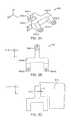
- FIG. 3Ais an isometric view of an object to be machined from a workpiece, illustrating structural features for which silhouetting can be useful when generating computer models of occupying structures in accordance with the present invention
- FIG. 3Bis a plan view of the object of FIG. 3A showing the extents of the object in the x-y directions;
- FIG. 3Cis a silhouette of the object of FIGS. 3A and 3B that can be used for generating one or more occupying structures around the object and/or locating the object relative to one or more other objects and/or a temporary support frame;
- FIG. 4is a screenshot of a window of CAD software showing a graphical representation of a workpiece computer model for creating eight identical objects from a single body of material, showing the workpiece computer model prior to generating an occupying structure to occupy an excess unoccupied region;
- FIG. 5is a screenshot of the window of FIG. 4 illustrating the manual addition of adding a graphical representation of an occupying structure to the workpiece computer model of FIG. 4 using an entity extrusion process;
- FIG. 6is a screenshot of the window of FIG. 4 illustrating certain steps of defining a graphical representation of a new channel of the workpiece;
- FIG. 7is a screenshot of the window of FIG. 4 illustrating additional steps of defining the graphical representation of the new channel
- FIG. 8is a screenshot of the window of FIG. 4 illustrating further steps of defining the graphical representation of the new channel
- FIG. 9is a screenshot of the window of FIG. 4 illustrating the finished graphical representation of the new channel
- FIG. 10is a screenshot of a window of CAD software illustrating creating workpiece computer model using a process of defining a graphical representation of an occupying structure manually using offsets;
- FIG. 11is a screenshot of the window of FIG. 11 showing the graphical representation of the occupying structure defined using offsets;
- FIG. 12is an isometric view of a graphical representation of a workpiece computer model for creating fourteen objects of three differing types from a single body of material prior to adding any occupying structure;
- FIG. 13is an isometric view of the graphical representation of FIG. 12 after modifying the workpiece to include an occupying structure in one of the excess unoccupied regions;
- FIG. 14is a high-level diagram illustrating a workpiece-layout system made in accordance with the present invention.
- FIG. 15is a high-level diagram illustrating a computing system suitable for use in implementing any one or more parts of a workpiece-layout system of the present disclosure, including the workpiece-layout system of FIG. 14 and steps of the method of FIG. 2 .
- the present inventionis directed to methods of reducing machining equipment usage during manufacturing of a plurality of discrete objects from a single body of material, or “workpiece.”
- a temporary support frameis provided, for example, to aid in handling, datum referencing, and/or object layout, among other things.
- discrete objectsthat can be manufactured using techniques disclosed herein include, but are not limited to, finished parts for assemblies (such as consumer products, military equipment, commercial equipment, among others), precursors to finished parts (such as precursors that required further processing to create finished assembly parts), finished standalone products, and precursors to finished standalone products, among others.
- a “precursor” to a finished part or finished objectis a discrete object, i.e., an object liberated from the body of material from which it is made, that requires further processing to become the finished part or finished object.
- FIGS. 1A to 1Cillustrate aspects of the present invention that result in savings of machining time, machining equipment wear, and cost of machining a given set of objects.
- FIG. 1Aillustrates a first workpiece 100 after machining from the obverse side 100 A of the first workpiece to create a first object 104 and a second object 108 from the same body of material.
- a result of the machiningalso forms a temporary support frame 112 that is used at certain steps of the machining process to stabilize the first and second objects.
- first workpiece 100it is first modeled with computer-modeling software using graphical representations of temporary support frame 112 and graphical representations of first and second objects 104 and 108 .
- the graphical representation of temporary support frame 112is used as a starting point for arranging the objects (here, first and second objects 104 and 108 ) within the workpiece. This is done by locating graphical representations of the objects, here, first and second objects 104 and 108 , within an opening of the graphical representation of temporary support frame 112 .
- an opening of the graphical representation of temporary support frame 112may be centrally located. It is further noted that an opening may be a through-opening of the graphical representation of temporary support frame.
- an opening of the graphical representation of temporary support frame 112may be a recess.
- a recessmay not be an opening and may be a recess that may be located within a graphical representation of temporary support frame 112 .
- a recessmay be of any appropriate depth.
- An opening and a recess, or an opening or a recess, and any appropriate number of eachmay be included in a graphical representation of temporary support frame 112 .
- openingmay be used interchangeably with recess. Since temporary support frame 112 and first and second objects 104 and 108 are the only structures to be made from workpiece 100 , when the workpiece is machined to create these structures, all of the material of the workpiece not part of these structures is machined away, here creating void 116 and void 120 (which are parts of the opening of the temporary support frame. Machining away that much material is time consuming and costly.
- FIG. 1Billustrates a second workpiece 130 for making the same first and second objects 104 and 108 .
- second workpiece 130includes frame 112 and first and second objects 104 and 108 .
- second workpiece 130includes a set of four occupying structures 134 ( 1 ) to 134 ( 4 ) that occupy what are referred to herein and in the appended claims as “excess unoccupied regions,” which are regions outside the silhouettes (see FIGS. 3A-3C and accompanying descriptions for silhouetting features) of first and second objects 104 and 108 and temporary support frame 112 that do not need to be machined away in order to form the first and second objects.
- occupying structures 134 ( 1 ) to 134 ( 4 )are defined in computer-modeling software by corresponding graphical representations that are essentially added to the graphical representations of temporary support frame 112 and first and second objects 104 and 108 .
- the graphical representations of occupying structures 134 ( 1 ) to 134 ( 4 )are then considered in the creation of the machine-control instruction set as structures to be machined from second workpiece 130 along with temporary support frame 112 and first and second objects 104 and 108 .
- occupying structures 134 ( 1 ) to 134 ( 4 )can be recycled, as can be temporary support frame 112 .
- occupying structures 134 ( 1 ) to 134 ( 4 )are simple geometric shapes that approximate the shapes of the corresponding excess unoccupied regions. In other instances, occupying structures may be complex geometric shapes following the contouring of non-rectilinear parts. As described below in detail, occupying structures 134 ( 1 ) to 134 ( 4 ) can be modeled manually by a user or automatically by a suitably capable workpiece-layout system.
- FIG. 1Ctakes the occupying-structure feature to an extreme with a third workpiece 150 that is also defined to create first and second objects 104 and 108 .
- third workpiece 150is defined to nearly completely minimize the amount of material that needs to be machined away to create first and second objects 104 and 108 by largely outlining the first and second objects with a gap that is based on the machine tool(s) plus an offset, if any, that is(are) used during the machining of the third workpiece, leaving everything beyond that gap outside the first and second objects untouched by the machining.
- a graphical representation of temporary support frame 112FIGS. 1A and 1B and shown via dashed lines in FIG.
- third workpiece 150 of FIG. 1Calso includes occupying structure 134 ( 1 ) also present in second workpiece 130 of FIG. 1B within an interior region of second object 108 .
- excess unoccupied regions and corresponding occupying structurescan be located between a pair of objects or among a group of three or more objects, depending on the shape(s) of the objects, their orientations relative to one another, the number of objects, and their locations relative to one another.
- the computer model for third workpiece 150 of FIG. 1Ccan be created manually or automatically, depending on the functionality of the modeling software used.
- the x, y, and z contours of any objectcan be defined to minimize the amount of material that needs to be machined away.
- the z contours of an objectmay also be defined to reduce the volume to be machined, which will in-turn reduce the amount of machining time.
- bodies of material from which the multiple discrete objects can be madeinclude, but are not limited to, plates, slabs, blooms, billets, boards, blocks, among many other shapes, including curvilinear and multisided shapes, and any combination thereof.
- the material composing the bodythe material may be any suitable material, such as metal (solid, sintered, etc.), polymer (solid, foamed, etc.), wood, composite, and multilayer material, among others.
- metalsolid, sintered, etc.
- polymersolid, foamed, etc.
- woodcomposite, and multilayer material
- Each machining process usedmay be any suitable process, such as, but not limited to, rotary-tool milling, electronic discharge machining, ablation, etching, erosion, cutting, and cleaving, among others.
- rotary-tool millingelectronic discharge machining
- ablationablation
- etchingerosion
- cuttingand cleaving
- milling equipmenthaving either a vertically or horizontally oriented spindle shaft(s).
- milling equipmentinclude bed mills, turret mills, C-frame mills, floor mills, gantry mills, knee mills, and ram-type mills, among others.
- the milling equipment used for removing materialmay be of the computerized numerical control (CNC) type that is automated and operates by precisely programmed commands that control movement of one or more parts of the equipment to effect the material removal.
- CNCcomputerized numerical control
- CNC machinestheir operation, programming, and relation to computer aided manufacturing (CAM) tools and computer aided design (CAD) tools are well known and need not be described in detail herein for those skilled in the art to understand the scope of the present invention and how to practice it in any of its widely varying forms.
- CAMcomputer aided manufacturing
- CADcomputer aided design
- Methods disclosed hereininclude methods of providing a workpiece computer model of a plurality of objects defined in a body of material.
- a workpiece computer modelmay include machine-control instruction sets, for example, numerical control (NC) instructions sets, for controlling machining equipment to machine a plurality of objects from a single workpiece in an efficient manner that seeks to minimize the amount of machining that needs to be performed, thereby reducing the wear on the machine and machine tools, and time needed to complete machining the workpiece.
- FIG. 2illustrates a method 200 , which is an example of such methods.
- aspects of some of the methods described herein, including method 200may be performed by a workpiece-layout system that runs computer software, such as CAD software and software for generating machine-control instructions sets from CAD models and/or other types of computer models of objects to be fabricated using the machine-control instructions provided by these methods.
- a workpiece-layout systemcan comprise any suitable computing system, including standalone computing systems and networked computing systems that can run conventional CAD software, CAM software, and the like.
- machine-control instructionsand like terms are used herein and in the appended claims to denote any instruction set needed to control any one or more types of machining equipment to perform the necessary machining and, as appropriate, any additional machine-control instructions for performing non-machining operations, such as controlling any robotic manipulator(s) and/or other equipment that automatically moves a workpiece before, during, or after machining operations.
- exemplary method 200includes a step 205 at which the workpiece-layout system may receive at the workpiece-layout system, a graphical representation of a temporary support frame that is to be machined from the body of material (or, again, “workpiece”), along with the discrete objects that are the subjects of the machining.
- step 205is exemplary and that exemplary method 200 may proceed without receiving a graphical representation of a temporary support frame.
- the graphical representation of the temporary support framemay be displayed.
- this methodmay be automated entirely or certain steps may be automated and that the method may or may not include interaction by a user. After reading this disclosure in its entirety, a person of ordinary skill in the art will readily appreciate the circumstances where an automated system may be desirable.
- the temporary support frame in this examplemay be used as part of an object-stabilizing scheme for holding the objects and their partially machined precursors in place.
- the temporary support framemay include an opening, defined by its inner periphery, that, after machining the workpiece from its first and second sides to create the discrete objects and temporary support frame, contains the discrete objects.
- the temporary support frameIn some embodiments in which the temporary support frame is rectangular in shape, it generally resembles a picture frame, with an opening being the region defined by the inner perimeter of the frame and its thickness. Examples of temporary support frames are depicted in various figures of the attached drawings.
- the workpiece-layout systemmay include a temporary-support-frame library containing graphical representations for multiple temporary support frames of differing sizes and/or thicknesses, wherein the multiple temporary support frames are configured for specific bodies of materials.
- a graphical representation of one temporary support framemay correspond to a stock piece of stainless steel that is 24.02′′ ⁇ 18.02′′ ⁇ 1′′.
- the temporary support framemay be 24′′ ⁇ 18′′ ⁇ 0.75′′ to account for, for example, aspects of the two-part machining of the first and second sides of the workpiece.
- a graphical representation for another temporary support framemay correspond to a stock piece of aluminum that is 36.02′′ ⁇ 24.02′′ ⁇ 3′′, and this temporary support frame may be 36′′ ⁇ 24′′ ⁇ 2.75′′.
- the workpiece-layout systemmay receive a selection of that graphical representation from the temporary-support-frame library (not shown). This selection may be accomplished in any one or more of a variety of ways, such as by user selection via a dialog box that displays either the multiple graphical representations of the differing temporary support frames or corresponding descriptors or filenames and allowing a user to select the desired one, allowing the user to drag and drop the desired graphical representation, or allowing the user to select the desired body of material and automatically selecting the corresponding graphical representation of the pertinent temporary support frame for the selected body of material, among others.
- such selection of the body of materialcan also be enabled in any one or more of a variety of ways, including via a dialog box that may displays either the multiple graphical representations of the differing available bodies of material or corresponding descriptors or filenames and allowing a user to select the desired one, among others.
- the usermay retrieve the graphical representation of the temporary support frame in any suitable manner, such as by receiving an identification of a computer-model file in an onscreen dialog box, dragging and dropping the graphical representation from one onscreen window to another onscreen window, copying and pasting the graphical representation from one onscreen window to another onscreen window, and any combination of these ways.
- a graphical representation of a temporary support framemay be displayed.
- all each of the process described abovemay completed automatically or automatedly.
- a workpiece-layout systemmay receive a graphical representation of a temporary support frame automatedly.
- a workpiece-layout systemmay select a temporary support frame from a temporary support frame library automatically as a function of a plurality of objects.
- a plurality of objectsmay be interrogated for attributes. Attributes may include geometric data and manufacturing data such as the tolerances, material used, finishes and other common manufacturing characteristics. Those of ordinary skill in the art, after reading this disclosure in its entirety will readily appreciate the various interrogatable attributes.
- a workpiece-layout systemmay automatically select a graphical representation of a temporary support frame, which may be automatically or automatedly received by the workpiece-layout system.
- the workpiece-layout systemreceives a selection of graphical representations of the plurality of objects to be machined from the workpiece.
- the workpiece-layout systemmay receive the selection in any of a variety of ways, including ways that are the same as or similar to ways known in conventional CAD software, such as SOLIDWORKS® CAD software, available from Dassault Systèmes Americas, Waltham, Mass., among others.
- Examples of ways of receiving a selection of graphical representations of a plurality of objects to be machinedinclude, but are not limited to, receiving an identification of one or more computer-model files in an onscreen dialog box, dragging and dropping one or more graphical representations from one onscreen window to another onscreen window that contains or will contain the representation of the temporary support frame, copying and pasting one or more graphical representations from one onscreen window to another onscreen window that contains or will contain the representation of the temporary support frame, and any combination of these ways.
- the selected graphical representations of the objects to be machinedmay be displayed on the graphical display along with the graphical representation of the temporary support frame.
- the workpiece-layout systemlocates the graphical representations of the plurality of objects in an opening of the graphical representation of the temporary support frame so that they are spaced from one another and from adjacent portions of the temporary support frame by one or more minimum distances that permits machining away material from in between immediately adjacent ones of the objects themselves and between various ones of the objects and the temporary support frame.
- the locating of the graphical representations that occurs at step 220typically results in the clustering of the graphical representations of the objects within the opening of the graphical representation of the temporary support frame into one or more clusters that leave one or more unoccupied regions.
- the size of the unoccupied region(s)can be to varying extents, including large extents, greater than the minimum regions that would need to be machined away to define and separate the objects during machining. Consequently, the machining away of the material in such excess unoccupied region(s) that would occur in the normal course, i.e., without intervention to minimize such machining, can significantly increase the time needed to machine the objects and temporary support frame from the body of material, as well as increase wear on the machining tools.
- one or more excess unoccupied regionscan occur between or among a set of graphical representations of objects.
- the locating of the graphical representations of the objects at step 220may be performed in any one or more of a variety of manners. For example, when the graphical representations of the objects may be received along with the graphical representation of the temporary support frame and the workpiece-layout system is so configured, the locating may be in response to a user's onscreen manipulation of those graphical representations, such as by dragging and dropping, snapping the representations to grid or other points, and keying in coordinates for reference points, among others or locating may occur automatically or automatedly.
- the workpiece-layout systemmay include a set of software instructions designed and configured to automatically perform the locating at step 220 .
- the SOLIDWORKS® CAD software mentioned abovehas a nesting feature that automatically nests, or locates, a plurality of graphical representations relative to one another in a manner that optimizes clustering of the objects to varying extents, depending on the shapes of the graphical representations and the nesting options selected.
- the workpiece-layout systemreceives an identification of one or more excess unoccupied regions within the opening of the graphical representation of the temporary support frame.
- the workpiece-layout system's receipt of the identification of each excess unoccupied region at step 225can be effected in any of a variety of ways.
- the receipt of the identificationcan occur via a user identifying each excess unoccupied region in any of a variety of ways.
- a usermay identify an excess unoccupied region by adding a graphical representation of an occupying structure to that excess unoccupied region.
- such an occupying structureis generally treated like an object to be formed from the multi-object workpiece in that it will not be machined away, but rather it will be formed from the workpiece during the machining process that forms the objects that are the desired end-products of the machining.
- machining time and effortcan be reduced because the workpiece material in the excess unoccupied region that would in the normal course be machined away based on a conventional CAM model of the objects and temporary support frame no longer will be machined away by virtue of the occupying structure.
- the usermay “click” at a location within an excess unoccupied region to identify it.
- the usermay make a selection, such as in a pop-up window or other user-control interface, that instructs the workpiece-layout system to identify each excess unoccupied region using, for example, automated excess unoccupied region identification algorithms.
- automated excess unoccupied region identification algorithmsmay be designed and configured to account for certain variables, such as the size(s) of the machining tool(s) that will be used during the machining of the workpiece to create the individual objects and temporary support frame.
- the automated excess unoccupied region identification algorithmsmay be programmed, for example, by user selection or other identification, of a minimum size for an excess unoccupied region below which the workpiece layout system ignores an excess unoccupied region. For example, if a particular excess unoccupied region has any dimension less than the diameter of the milling tool used to define the objects and temporary support frame, then the workpiece layout system will ignore it and let it be treated as a region to be machined away during machining.
- the workpiece-layout systemgenerates a graphical representation of an occupying structure occupying a corresponding one of the excess unoccupied regions identified in connection with step 225 .
- the workpiece-layout systemcan generate the graphical representation of each occupying structure in any one or more of a number of manners.
- a usercan create the graphical representation of the occupying structure using any suitable entity-creation and/or manipulation function(s) of the computer modeling, for example, CAD, software being used to view and manipulate the graphical representations of the objects and temporary support frame.
- the workpiece-layout systemincludes features and functionality designed and configured specifically for creating occupying structures for multi-object workpieces.
- features and functionalityinclude dialog boxes that allow a user to specify minimum offset(s) between graphical representations of occupying structures and graphical representations of objects to allow for machining, dialog boxes that allow a user to specify automatically created mechanical interlock structures, and a feature that allows a user to select an excess unoccupied region and specify any required variables that allow the workpiece layout system to automatically generate the occupying structure.
- the minimum offset(s) between graphical representations of occupying structures and graphical representations of objects to allow for machiningmay be determined based on the minimum relevant dimension of the machining tool(s), such as diameter(s) of milling bit(s), that will be used for machining the objects. For example, when the machining equipment includes an end mill, the offset may be set equal to the diameter of the end mill's bit plus an additional amount for refining operations.
- the workpiece-layout systemmay include occupying-structure-defining algorithms for automatically determining the extents of each occupying structure based on any variable(s) established by a user, such as the machining tool information mentioned above.
- an occupying structurewill result in a modification to the temporary support frame such that the occupying structure is continuous with the temporary support frame.
- An example of a case in which an occupying structure is part of the temporary support frameis described below in a detailed example.
- an occupying structurewill effectively be an island structure, surrounded by one or more of the objects being formed from the workpiece.
- an island-type occupying structuremay be provided with interlock structures.
- FIGS. 3A to 3Cillustrate a silhouetting process that can be used to optimize the shape of each occupying structure adjacent an object having structural features that complicate the process of determining suitable occupying structure(s).
- the object 300FIGS. 3A and 3B ) has upper-facing (relative to FIG.
- silhouettingcan be used to ensure that each corresponding occupying structure for a given object is properly defined in the graphical model so that the machine-control instructions that the workpiece-layout system ultimately generates are efficient and create the desired occupying structure(s).
- FIGS. 3B and 3CFor object 300 , wherein in FIG. 3B the object is being viewed along the z-axis (plunge axis) and in FIG. 3C the silhouette 312 of the object along the z-axis (plunge axis) is presented.
- a lateral offset, O, in an x-y plane for any occupying structure, here occupying structure 316can be set, for example, in the manner indicated above to account for one or more of the machining tools that will be used to machine the workpiece.
- the workpiece-layout systemmay generate a workpiece computer model including plurality of objects defined in a body of material. Additionally, a machine-control instruction set for machining the workpiece to create the multiple end-product objects desired to be created from the workpiece may be generated and may also be associated with a workpiece computer model.
- the generated machine-control instruction setcontains the instructions for controlling the one or more pieces of numerical control (NC) machining equipment, such as one or more NC milling machines, to perform the machining on the workpiece to create the objects and, as a byproduct of such machining, to create the occupying structure(s) and the temporary support frame, including any version thereof modified by one or more occupying structures as noted above.
- NCnumerical control
- the generating of the machine-control instruction setaccounts for, among other things, 1) the graphical representations of i) the objects, ii) the occupying structure(s) generated at step 230 , and iii) the temporary support frame (including any interlock structure(s) and any modifications made thereto to define an occupying structure generated at step 230 , 2) the machining equipment, including any particular tool(s), 3) the actual dimensions of the body of material forming the workpiece, 4) any datum(s) provided to properly locate the workpiece relative to the machining equipment, and 5) separate machining steps for forming valleys from an obverse side of the workpiece and for removing interconnecting portions from the reverse side that connect the objects to one another and/or to the temporary support frame and/or the occupying structure(s).
- the machine-control instruction setincludes instructions for directing the cutting tool of the end mill along a first path on the obverse side of the workpiece that forms 1) the valleys that define portions of the openings among the multiple objects that define the objects, inner portion(s) of the temporary support frame, and one or more portions of each occupying structure, 2) the interlock features on the inner periphery of the temporary support frame, including any occupying structure, if any, that modified the starting temporary support frame and on any island-type occupying structure, if any, and 3) any cavity or other surface feature, if any, on any one or more of the objects.
- Such a machine-control instruction setmay also include instructions for directing the cutting tool (or a different cutting tool) of the end mill along a second path on the reverse side of the workpiece in which any surfaces and/or surface features on the objects, if any, are machined.
- the machine-control instruction setmay be generated as a function of 1) the specific machining tool(s) (e.g., milling bit(s)) that will be used during the machining of the workpiece to create the multiple objects as well as 2) the size of the body of material that becomes the workpiece.
- the specific machining tool(s)have been at least partially accounted for in the process of defining the offsets for the objects and any occupying structures.
- the size of the workpieceis used to define where the machining equipment will actually be removing material and engaging the workpiece.
- Other inputssuch as type of material (e.g., to control machining speed), may also be used for generating the machine-control instruction set as needed or desired.
- the generation of the machine-control instruction setmay be performed automatically, such as by intelligent CAM software (e.g., CAMWORKS® software available from Geometric Technologies, Inc., Scottsdale, Ariz.), performed semi-automatically with the assistance of a user (such as when the CAM software does not have intelligence on how to handle certain physical features), or under the complete control of a user.
- intelligent CAM softwaree.g., CAMWORKS® software available from Geometric Technologies, Inc., Scottsdale, Ariz.
- CAMWORKS® softwareavailable from Geometric Technologies, Inc., Scottsdale, Ariz.
- FIGS. 4-9illustrate a simple example of creating a workpiece computer model 400 (illustrated in the figures by graphical representations generated by computer modeling software, such as CAD software) of a workpiece for providing eight identical objects (illustrated in the figures by graphical representations 404 ( 1 ) to 404 ( 8 )) located in an opening of a suitable temporary support frame (illustrated in the figures by graphical representations 408 A and 408 , respectively). As seen in FIG.
- this exampleis directed to generating a graphical representation 900 ( FIG. 9 ) of an occupying structure that, in this example, can be characterized as an extension of a portion of graphical representation 408 of the temporary support frame.
- a first step of generating graphical representation 900 ( FIG. 9 ) of occupying structure within the modeling softwaremay be to use a suitable sketch function of the modeling software to make a sketch 500 of a rectangle on the back face (relative to FIG. 5 ) of graphical representation 408 of temporary support frame that connects the three portions of the graphical representation of temporary support frame bordering unoccupied region 412 .
- the offset between objects 404 ( 4 ) and 404 ( 8 ) and occupying structure 900 ( FIG. 9 )is 0.28′′ to accommodate 1 ⁇ 4-inch milling bit plus a machining offset.
- rectangle sketch 500is located 0.28′′ away from the edges of objects 404 ( 4 ) and 404 ( 8 ) closest to the rectangle sketch.
- rectangle sketch 500is extruded using a suitable function of the modeling software to the upper face 412 A of temporary support frame 412 to define a solid rectangular prism entity 600 ( FIG. 6 ).
- Such sketching and extrusion operationsare well known in the art as are other software modeling functions described below.
- edge 600 ( 1 ) of rectangular prism entity 600is converted to a line 604 on upper face 412 A to allow for creating a new sketch 608 for defining features of graphical representations 904 and 908 ( FIG. 9 ) of, respectively, a shelf and a channel.
- an offset line 612 on upper face 412 Ais created at an offset of 0.5′′, which is the width of the shelf containing the channel. This offset can be created using any suitable function(s) available in the modeling software, such as an offset line function.
- lines 616 and 620 connecting lines 604 and 612can be created to form a first rectangle 624 .
- a second rectangle 628can be formed at an offset of 0.1′′, for example, using an offset function available in the modeling software.
- a rectangular tubular extrusion 700can be extruded to the bottom face of graphical representation 412 of the temporary support frame using a suitable extrusion function of the modeling software, and the z-axis location of upper end 700 A of the tubular extrusion can be set, for example, using a suitable locating function (such as the illustrated “Up To Surface” function) of the modeling software and referencing a surface at the same z-axis location, such as surface 704 .
- a suitable locating functionsuch as the illustrated “Up To Surface” function
- FIG. 9of the channel can be formed by performing a similar upper end locating operation on rectangular extrusion 800 ( FIG. 8 ) and selecting surface 804 as the reference surface, and then specifying that all vertical corners of the depression 908 ( FIG. 9 ) created by this step have a radius of 0.15′′.
- the result of all of these operationsare illustrated in FIG. 9 , in which it is seen that the graphical representation 900 of the occupying structure is now configured like the graphical representation 412 of the rest of the temporary support frame relative to the channels and excess area 412 is now part of the frame.
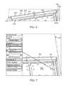
- FIGS. 10 and 11illustrate initial steps in defining a graphical representation (not shown) of an occupying structure for occupying an excess unoccupied region 1000 ( FIG. 10 ) within a workpiece computer model 1100 ( FIG. 11 ) that includes graphical representations 1104 ( 1 ) to 1104 ( 5 ), 1108 ( 1 ) to 1108 ( 3 ), 1112 ( 1 ) to 1112 ( 3 ), 1116 ( 1 ) to 1116 ( 3 ), 1120 , and 1124 ( FIG. 11 ), respectively, of 1) five differing types of objects to be made from the modeled workpiece and 2) a temporary support frame. As seen in FIG.
- a line-offset function available in the modeling softwareallows a user to draw lines, such as lines 1004 ( 1 ) to 1004 ( 9 ), that are offset by a set distance, here 0.28′′, from corresponding edges 1008 ( 1 ) to 1008 ( 9 ) of graphical representations 1108 ( 2 ) and 1104 ( 2 ) to 1104 ( 4 ). As seen in FIG.
- lines 1004 ( 1 ) to 1004 ( 9 ) and similar lines 1128 ( 1 ) to 1128 ( 9 )can then be joined, along with similar lines (unlabeled), to define a continuous line 1128 that can then be used in a process to create a graphical representation (not shown, but would occupy hatched region 1132 ) of an occupying structure that occupies excess unoccupied region 1000 .
- the process used to create the graphical representation (not shown) of an occupying structuremay be an extrusion process the same as or similar to the extrusion process described above in connection with FIGS. 4-9 .
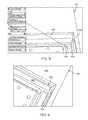
- FIGS. 12 and 13illustrate, respectively, a workpiece computer model 1200 and 1200 ′ before and after adding a graphical representation 1300 ( FIG. 13 ) of an occupying structure to the primary unoccupied region 1204 ( FIG. 12 ) of workpiece computer model 1200 , which in this case is between the graphical representation 1208 of the temporary support frame and the cluster 1212 of graphical representations 1216 , 1220 ( 1 ) to 1220 ( 4 ), and 1224 ( 1 ) to 1224 ( 9 ) of three differing types of objects to be made from the workpiece represented by computer model 1200 ′.
- graphical representation 1300 ( FIG. 13 ) of the occupying structureis essentially provided as an extension to the graphical representation 1208 of the temporary support frame.
- FIG. 13It is seen in FIG. 13 that the graphical representations 1228 ( 1 ) to 1228 ( 4 ) of FIG. 12 of channels formed in shelves of the graphical representation 1208 of the temporary support frame are effectively replaced in computer model 1200 ′ ( FIG. 13 ) with a graphical representation 1304 of a single continuous channel formed in a single continuous shelf.
- Graphical representation 1300 of the occupying structuremay have been created automatically or manually, for example, using any of the suitable techniques described above.
- the formation of cluster 1212 of graphical representations 1216 , 1220 ( 1 ) to 1220 ( 4 ), and 1224 ( 1 ) to 1224 ( 9 ) of three differing types of objectsmay have been created automatically or manually, for example, using any of the suitable techniques described above.
- FIG. 14illustrates an exemplary workpiece-layout system 1400 that can perform methods of the present disclosure, including method 200 of FIG. 2 , to create a workpiece computer model 1404 for automatically machining a plurality of objects 1408 from a single workpiece 1412 using one or more pieces of machining equipment 1416 .
- workpiece-layout system 1400includes computer-modeling software 1420 , such as CAD software, that allows a user to create, build, modify, etc., computer models of various structures via graphical representations displayed to use on one or more graphical displays and manipulated by the user using one or more computer input devices.
- computer-modeling software 1420such as CAD software
- computer-modeling software 1420An example of such software that can be part of computer-modeling software 1420 is SOLIDWORKS® CAD software, but any of many others, can be used to provide three-dimensional (3D) modeling functionality.
- a usercan use computer-modeling software 1420 , for example, in a manner described above, to create workpiece computer model 1404 “manually,” i.e., using conventional drawing commands native to commercial off-the-shelf (COTS) computer modeling software.
- COTScommercial off-the-shelf
- computer-modeling software 1420can include COTS CAD software that is augmented with custom software, such as via one or more plugin software modules, that automates and/or otherwise assists the user in efficiently building a workpiece computer model, such as workpiece computer model 1404 .
- computer-modeling software 1420can be entirely custom software built for the specific task of building workpiece computer models, such as workpiece computer model 1404 .
- the form of computer-modeling software 1420can be any suitable form that provides the requisite functionality.
- workpiece-layout system 1400may include a stock-materials datastore 1424 and a corresponding stock-frames datastore 1428 that contain, respectively, stock-material definitions 1424 ( 1 ) to 1424 (N) (e.g., sizes, material type, etc.) of bodies of material typically used and preconfigured frame computer models 1428 ( 1 ) to 1428 (N) of temporary support frames suitable for use with corresponding respective stock bodies of material.
- stock-materials datastore 1424 and a corresponding stock-frames datastore 1428that contain, respectively, stock-material definitions 1424 ( 1 ) to 1424 (N) (e.g., sizes, material type, etc.) of bodies of material typically used and preconfigured frame computer models 1428 ( 1 ) to 1428 (N) of temporary support frames suitable for use with corresponding respective stock bodies of material.
- computer-modeling software 1420may include a user interface (UI) designed and configured to allow a user to select a desired one of stock-material definitions 1424 ( 1 ) to 1424 (N) and/or a desired one of preconfigured frame computer models 1428 ( 1 ) to 1428 (N) for use in creating a particular workpiece computer model.
- UIuser interface
- stock-materials datastore 1424 and/or stock-frames datastore 1428are not provided, a user can import them into workpiece-layout system 1400 as needed or create them as needed, for example, using computer-modeling software 1400 .
- workpiece-layout system 1400may also include an object-model datastore 1432 that stores computer models 1432 ( 1 ) to 1432 (N) of objects to be made from workpieces modeled using the workpiece-layout system.
- object-model datastore 1432stores computer models 1432 ( 1 ) to 1432 (N) of objects to be made from workpieces modeled using the workpiece-layout system.
- computer models of objects to be madecan be stored elsewhere and imported into workpiece-layout system 1400 when needed and/or created using computer-modeling software 1420 .
- computer-modeling software made in accordance with the present inventionmay include clustering algorithms 1436 designed and configure to automatically cluster the object models within a selected temporary support frame in a manner that minimizes the amount of machining that needs to be performed, for example, by maximizing consolidation of the excess unoccupied regions into as few relatively large excess unoccupied regions as possible, to create the objects from the workpiece modeled using workpiece-layout system 1400 .
- Computer-modeling software 1420may also include any suitable UI(s) 1440 that allow a user to implement clustering algorithms 1436 .
- computer-modeling software made in accordance with the present inventionmay include excess unoccupied region identification algorithms 1444 for automatically identifying any excess unoccupied regions within a workpiece computer model that may each be suitable for receiving a computer model of a corresponding occupying structure that does not get machined away during machining of the modeled workpiece.
- computer-modeling software 1420may include one or more UIs 1448 that allow a user to input any information needed to allow excess unoccupied region identification algorithms 1444 to function properly. Exemplary details of functionalities and inputs that can be involved with excess unoccupied region identification algorithms 1444 are described above in connection with step 225 of method 200 of FIG. 2 .
- computer-modeling software of the present inventionmay also include occupying-structure-defining algorithms 1452 for automatically defining computer models for the occupying structures that do not get machined away during machining of the modeled workpiece.
- Computer-modeling software 1420may also include one or more UIs 1456 that allow a user to input any information needed to allow occupying-structure-defining algorithms 1452 to function properly. Exemplary details of functionalities and inputs that can be involved with occupying-structure-defining algorithms 1452 are described above in connection with step 230 of method 200 of FIG.
- Algorithms 1436 , 1444 , and 1452 and any corresponding functionalities and UIs, such as UIs 1440 , 1448 , and 1456may be implemented, for example, via one or more plugin modules or implemented within a core of the computer-modeling software itself.
- these and other customizationscould be made to an extent that the only inputs needed are an indication of the computer models of the objects to be machined and an instruction to create the workpiece-computer model, and perhaps an indication of the material from which the objects are to be made if workpiece-layout system 1400 is being used to create workpiece computer models for differing materials.
- Workpiece layout system 1400may further include CAM software 1460 designed and configured to generate, for each workpiece computer model 1404 , a machine-control instruction set 1464 that controls machining equipment 1416 during the machining of workpiece 1412 to create plurality of objects 1408 therefrom, as well as to create the temporary support frame 1468 and any occupying structure(s) 1472 that are generally remnants of the machining.
- CAM software 1460may include COTS CAM software, such as CAMWORKS®, CAM software, or any other suitable software that can utilize workpiece computer model 1404 to generate machine-control instruction set 1464 , for example, in the manner described above in connection with step 235 of method 200 of FIG. 2 .
- any one or more of the aspects and embodiments described hereinmay be conveniently implemented using one or more machines (e.g., one or more computing devices that are utilized as a user computing device for an electronic document, one or more server devices, such as a document server, etc.) programmed according to the teachings of the present specification, as will be apparent to those of ordinary skill in the computer art.
- Appropriate software codingcan readily be prepared by skilled programmers based on the teachings of the present disclosure, as will be apparent to those of ordinary skill in the software art.
- Aspects and implementations discussed above employing software and/or software modulesmay also include appropriate hardware for assisting in the implementation of the machine executable instructions of the software and/or software module.
- Such softwaremay be a computer program product that employs a machine-readable storage medium.
- a machine-readable storage mediummay be any medium that is capable of storing and/or encoding a sequence of instructions for execution by a machine (e.g., a computing device) and that causes the machine to perform any one of the methodologies and/or embodiments described herein. Examples of a machine-readable storage medium include, but are not limited to, a magnetic disk, an optical disc (e.g., CD, CD-R, DVD, DVD-R, etc.), a magneto-optical disk, a read-only memory “ROM” device, a random access memory “RAM” device, a magnetic card, an optical card, a solid-state memory device, an EPROM, an EEPROM, and any combinations thereof.
- a machine-readable mediumis intended to include a single medium as well as a collection of physically separate media, such as, for example, a collection of compact discs or one or more hard disk drives in combination with a computer memory.
- a machine-readable storage mediumdoes not include transitory forms of signal transmission.
- Such softwaremay also include information (e.g., data) carried as a data signal on a data carrier, such as a carrier wave.
- a data carriersuch as a carrier wave.
- machine-executable informationmay be included as a data-carrying signal embodied in a data carrier in which the signal encodes a sequence of instruction, or portion thereof, for execution by a machine (e.g., a computing device) and any related information (e.g., data structures and data) that causes the machine to perform any one of the methodologies and/or embodiments described herein.
- Examples of a computing deviceinclude, but are not limited to, an electronic book reading device, a computer workstation, a terminal computer, a server computer, a handheld device (e.g., a tablet computer, a smartphone, etc.), a web appliance, a network router, a network switch, a network bridge, any machine capable of executing a sequence of instructions that specify an action to be taken by that machine, and any combinations thereof.
- a computing devicemay include and/or be included in a kiosk.
- FIG. 15shows a diagrammatic representation of one embodiment of a computing device in the exemplary form of a computer system 1500 within which a set of instructions for causing a control system, such as the workpiece-layout system 1400 of FIG. 14 , to perform any one or more of the aspects and/or methodologies of the present disclosure may be executed.
- a control systemsuch as the workpiece-layout system 1400 of FIG. 14
- Computer system 1500includes a processor 1504 and a memory 1508 that communicate with each other, and with other components, via a bus 1512 .
- Bus 1512may include any of several types of bus structures including, but not limited to, a memory bus, a memory controller, a peripheral bus, a local bus, and any combinations thereof, using any of a variety of bus architectures.
- Memory 1508may include various components (e.g., machine-readable media) including, but not limited to, a random access memory component, a read only component, and any combinations thereof.
- a basic input/output system 1516(BIOS), including basic routines that help to transfer information between elements within computer system 1500 , such as during start-up, may be stored in memory 1508 .
- Memory 1508may also include (e.g., stored on one or more machine-readable media) instructions (e.g., software) 1520 embodying any one or more of the aspects and/or methodologies of the present disclosure, such as one or more aspects of FIGS. 1-5 .
- memory 1508may further include any number of program modules including, but not limited to, an operating system, one or more application programs, other program modules, program data, and any combinations thereof.
- Computer system 1500may also include a storage device 1524 , which may be used to implement datastores 1424 , 1428 , and 1432 , among other aspects of the present disclosure.
- a storage devicee.g., storage device 1524
- Examples of a storage deviceinclude, but are not limited to, a hard disk drive, a magnetic disk drive, an optical disc drive in combination with an optical medium, a solid-state memory device, and any combinations thereof.
- Storage device 1524may be connected to bus 1512 by an appropriate interface (not shown).
- Example interfacesinclude, but are not limited to, SCSI, advanced technology attachment (ATA), serial ATA, universal serial bus (USB), IEEE 1194 (FIREWIRE), and any combinations thereof.
- storage device 1524(or one or more components thereof) may be removably interfaced with computer system 1500 (e.g., via an external port connector, not shown).
- storage device 1524 and an associated machine-readable medium 1528may provide nonvolatile and/or volatile storage of machine-readable instructions, data structures, program modules, and/or other data for computer system 1500 , which in some implementations and embodiments may transform at least part of the computer system into an electronic pricing machine, as described hereinabove.
- software 1520may reside, completely or partially, within machine-readable medium 1528 .
- software 1520may reside, completely or partially, within processor 1504 .
- Computer system 1500may also include an input device 1532 .
- a user of computer system 1500may enter commands and/or other information into computer system 1500 via input device 1532 .
- Examples of an input device 1532include, but are not limited to, an alpha-numeric input device (e.g., a keyboard), a pointing device, a joystick, a gamepad, an audio input device (e.g., a microphone, a voice response system, etc.), a cursor control device (e.g., a mouse), a touchpad, an optical scanner, a video capture device (e.g., a still camera, a video camera), a touchscreen, and any combinations thereof, among others.
- an alpha-numeric input devicee.g., a keyboard
- a pointing devicee.g., a joystick, a gamepad
- an audio input devicee.g., a microphone, a voice response system, etc.
- a cursor control devicee.g.,
- Input device 1532may be interfaced to bus 1512 via any of a variety of interfaces (not shown) including, but not limited to, a serial interface, a parallel interface, a game port, a USB interface, a FIREWIRE interface, a direct interface to bus 1512 , and any combinations thereof.
- Input device 1532may include a touch screen interface that may be a part of or separate from display 1536 , discussed further below.
- Input device 1532may be utilized as a user selection device for selecting one or more graphical representations in a graphical interface as described above.
- a usermay also input commands and/or other information to computer system 1500 via storage device 1524 (e.g., a removable disk drive, a flash drive, etc.) and/or network interface device 1540 .
- storage device 1524e.g., a removable disk drive, a flash drive, etc.
- network interface device 1540may be utilized for connecting computer system 1500 to one or more of a variety of networks, such as network 1544 , and one or more remote devices 1548 connected thereto.
- Examples of a network interface deviceinclude, but are not limited to, a network interface card (e.g., a mobile network interface card, a LAN card), a modem, and any combination thereof.
- Examples of a networkinclude, but are not limited to, a wide area network (e.g., the Internet, an enterprise network), a local area network (e.g., a network associated with an office, a building, a campus or other relatively small geographic space), a telephone network, a data network associated with a telephone/voice provider (e.g., a mobile communications provider data and/or voice network), a direct connection between two computing devices, and any combinations thereof.
- a networksuch as network 1544 , may employ a wired and/or a wireless mode of communication. In general, any network topology may be used.
- Informatione.g., data, software 1520 , etc.
- Computer system 1500may further include a video display adapter 1552 for communicating a displayable image, such as one or more prices and/or lists of suppliers, to a display device, such as display device 1536 .
- a display deviceinclude, but are not limited to, a liquid crystal display (LCD), a cathode ray tube (CRT), a plasma display, a light emitting diode (LED) display, and any combinations thereof.
- Display adapter 1552 and display device 1536may be utilized in combination with processor 1504 to provide graphical representations of aspects of the present disclosure.
- computer system 1500may include one or more other peripheral output devices including, but not limited to, an audio speaker, a printer, and any combinations thereof.
- peripheral output devicesmay be connected to bus 1512 via a peripheral interface 1556 . Examples of a peripheral interface include, but are not limited to, a serial port, a USB connection, a FIREWIRE connection, a parallel connection, and any combinations thereof.
- the conjunctive phrases in the foregoing examples in which the conjunctive list consists of X, Y, and Zshall each encompass: one or more of X; one or more of Y; one or more of Z; one or more of X and one or more of Y; one or more of Y and one or more of Z; one or more of X and one or more of Z; and one or more of X, one or more of Y and one or more of Z.
Landscapes
- Engineering & Computer Science (AREA)
- Human Computer Interaction (AREA)
- Manufacturing & Machinery (AREA)
- Physics & Mathematics (AREA)
- General Physics & Mathematics (AREA)
- Automation & Control Theory (AREA)
- Numerical Control (AREA)
Abstract
Description
Claims (19)
Priority Applications (1)
| Application Number | Priority Date | Filing Date | Title |
|---|---|---|---|
| US15/871,191US10401824B2 (en) | 2016-04-14 | 2018-01-15 | Methods and software for reducing machining equipment usage when machining multiple objects from a single workpiece |
Applications Claiming Priority (3)
| Application Number | Priority Date | Filing Date | Title |
|---|---|---|---|
| US201662322275P | 2016-04-14 | 2016-04-14 | |
| US201715487395A | 2017-04-13 | 2017-04-13 | |
| US15/871,191US10401824B2 (en) | 2016-04-14 | 2018-01-15 | Methods and software for reducing machining equipment usage when machining multiple objects from a single workpiece |
Related Parent Applications (1)
| Application Number | Title | Priority Date | Filing Date |
|---|---|---|---|
| US201715487395AContinuation | 2016-04-14 | 2017-04-13 |
Publications (2)
| Publication Number | Publication Date |
|---|---|
| US20180150048A1 US20180150048A1 (en) | 2018-05-31 |
| US10401824B2true US10401824B2 (en) | 2019-09-03 |
Family
ID=62190202
Family Applications (1)
| Application Number | Title | Priority Date | Filing Date |
|---|---|---|---|
| US15/871,191ActiveUS10401824B2 (en) | 2016-04-14 | 2018-01-15 | Methods and software for reducing machining equipment usage when machining multiple objects from a single workpiece |
Country Status (1)
| Country | Link |
|---|---|
| US (1) | US10401824B2 (en) |
Families Citing this family (2)
| Publication number | Priority date | Publication date | Assignee | Title |
|---|---|---|---|---|
| US10545481B2 (en)* | 2016-12-28 | 2020-01-28 | Proto Labs Inc | Methods and software for providing graphical representations of a plurality of objects in a central through opening |
| CN114740797B (en)* | 2022-04-27 | 2025-05-23 | 华南理工大学 | A method for generating machining trajectories of two-dimensional cavity multi-tool combination machining with constant load rate |
Citations (175)
| Publication number | Priority date | Publication date | Assignee | Title |
|---|---|---|---|---|
| US4495559A (en) | 1981-11-02 | 1985-01-22 | International Business Machines Corporation | Optimization of an organization of many discrete elements |
| US5117354A (en) | 1988-05-24 | 1992-05-26 | Carnes Company, Inc. | Automated system for pricing and ordering custom manufactured parts |
| CN2112190U (en) | 1991-07-27 | 1992-08-05 | 殷为民 | Simple electronic-control led display screen |
| US5465221A (en) | 1993-12-30 | 1995-11-07 | The United States Of America As Represented By The Secretary Of The Air Force | Automated process planning for quality control inspection |
| US5495430A (en) | 1991-12-13 | 1996-02-27 | Kabushiki Kaisha Toyota Chuo Kenkyusho | Process time estimating apparatus |
| US5552995A (en) | 1993-11-24 | 1996-09-03 | The Trustees Of The Stevens Institute Of Technology | Concurrent engineering design tool and method |
| US5570291A (en) | 1994-08-24 | 1996-10-29 | Wallace Computer Services, Inc. | Custom product estimating and order processing system |
| US5655087A (en) | 1993-05-17 | 1997-08-05 | Nec Corporation | CAD system capable of calculating costs during CAD operation |
| US5758328A (en) | 1996-02-22 | 1998-05-26 | Giovannoli; Joseph | Computerized quotation system and method |
| US5815398A (en)* | 1996-01-16 | 1998-09-29 | Massachusettes Institute Of Technology | Method and apparatus for placing parts in a bounded region |
| US5847971A (en) | 1996-01-05 | 1998-12-08 | Steelcase Incorporated | 3-D spatial GUI querying and manipulating an RDMS for order-entry applications |
| US5870719A (en) | 1996-07-03 | 1999-02-09 | Sun Microsystems, Inc. | Platform-independent, usage-independent, and access-independent distributed quote configuraton system |
| US5937189A (en) | 1996-11-12 | 1999-08-10 | International Business Machines Corporation | Object oriented framework mechanism for determining configuration relations |
| US6031535A (en) | 1996-06-27 | 2000-02-29 | Sun Microsystems, Inc. | Nodal model for status based dynamic display of user interface controls |
| US6112133A (en) | 1998-02-27 | 2000-08-29 | Imcs, Inc. | Visual system and method for generating a CNC program for machining parts with planar and curvilinear surfaces |
| US6240332B1 (en)* | 1994-04-29 | 2001-05-29 | The Boeing Company | Tooling head controller |
| US20010023418A1 (en) | 2000-03-15 | 2001-09-20 | Noriyasu Suzuki | Method and apparatus for estimating product cost |
| US6295513B1 (en) | 1999-03-16 | 2001-09-25 | Eagle Engineering Of America, Inc. | Network-based system for the manufacture of parts with a virtual collaborative environment for design, developement, and fabricator selection |
| WO2001077781A2 (en) | 2000-04-07 | 2001-10-18 | Optimation, Inc. | Method and system to obtain automatic quotations from manufacturing details |
| US20010047251A1 (en) | 2000-03-03 | 2001-11-29 | Kemp William H. | CAD system which designs 3-D models |
| US6341271B1 (en) | 1998-11-13 | 2002-01-22 | General Electric Company | Inventory management system and method |
| US6343285B1 (en) | 1997-10-20 | 2002-01-29 | Sumitomo Heavy Industries, Ltd. | Estimation and designing supporting apparatus |
| US20020065790A1 (en) | 2000-11-20 | 2002-05-30 | Toshihiro Oouchi | Cost estimation method, cost estimation apparatus, product manufacturing estimation method and product manufacturing estimation apparatus |
| US20020087440A1 (en) | 2000-12-29 | 2002-07-04 | Blair William R. | Method for reconstructing and validating a bill of materials and creating a comprehensive bill of materials |
| US20020099579A1 (en) | 2001-01-22 | 2002-07-25 | Stowell David P. M. | Stateless, event-monitoring architecture for performance-based supply chain management system and method |
| US20020107673A1 (en) | 2001-02-08 | 2002-08-08 | Haller Kirk D. | Automated connections of computer-aided design components |
| US20020152133A1 (en) | 2001-03-09 | 2002-10-17 | King John Thorne | Marketplaces for on-line contract negotiation, formation, and price and availability querying |
| US20030018490A1 (en) | 2001-07-06 | 2003-01-23 | Marathon Ashland Petroleum L.L.C. | Object oriented system and method for planning and implementing supply-chains |
| US20030069824A1 (en) | 2001-03-23 | 2003-04-10 | Restaurant Services, Inc. ("RSI") | System, method and computer program product for bid proposal processing using a graphical user interface in a supply chain management framework |
| US20030078846A1 (en) | 2001-03-23 | 2003-04-24 | Burk Michael James | System, method and computer program product for auditing performance in a supply chain framework |
| US20030139995A1 (en) | 2002-01-23 | 2003-07-24 | Frankie Farley | CyberSTEEL dynamo internet based procurement and price risk management method and trading system |
| US20030149500A1 (en) | 2002-02-01 | 2003-08-07 | M. Omar Faruque | System And Method Of Interactively Assembling A Model |
| US6611725B1 (en) | 2000-02-03 | 2003-08-26 | Solidworks Corporation | Computer drawing system |
| US20030163212A1 (en) | 2002-02-25 | 2003-08-28 | Smith Kevin Scott | Method and system for manufacture of parts |
| US20030172008A1 (en) | 2002-03-08 | 2003-09-11 | Agile Software Corporation | System and method for managing and monitoring supply costs |
| US6647373B1 (en) | 1998-12-24 | 2003-11-11 | John Carlton-Foss | Method and system for processing and transmitting electronic reverse auction information |
| US20030212610A1 (en) | 2000-02-25 | 2003-11-13 | Duffy Christopher A. | System and method for specification and exchange management |
| US20030220911A1 (en) | 2002-05-23 | 2003-11-27 | Tompras Anthony D. | Solid model library tool |
| US20040008876A1 (en) | 2002-07-09 | 2004-01-15 | Deus Technologies, Llc | Input/output interface for computer aided diagnosis (CAD) system |
| US6690990B1 (en)* | 2002-12-02 | 2004-02-10 | CENTRE DE RECHERCHE INDUSTRIELLE DU QUéBEC | Method of optimizing a layout of selected parts to be cut |
| US6701200B1 (en) | 2001-12-27 | 2004-03-02 | The Protomold Company, Inc. | Automated custom mold manufacture |
| US6750864B1 (en) | 1999-11-15 | 2004-06-15 | Polyvista, Inc. | Programs and methods for the display, analysis and manipulation of multi-dimensional data implemented on a computer |
| US20040113945A1 (en) | 2002-12-12 | 2004-06-17 | Herman Miller, Inc. | Graphical user interface and method for interfacing with a configuration system for highly configurable products |
| US20040195224A1 (en) | 2003-04-02 | 2004-10-07 | Kanodia Vinod L. | Automated weld location system for vehicles |
| US6834312B2 (en) | 2000-05-02 | 2004-12-21 | Cadopener.Com 11C | Method and apparatus for delivery of data over a network |
| US6836699B2 (en) | 2001-12-27 | 2004-12-28 | The Protomold Company, Inc. | Automated quoting of molds and molded parts |
| US6859768B1 (en) | 2000-03-03 | 2005-02-22 | The Beck Technology | Computer-implemented automated building design and modeling and project cost estimation and scheduling system |
| US20050055299A1 (en) | 2000-02-23 | 2005-03-10 | Phyllis Chambers | System and method for facilitating a request for proposal process |
| US20050125092A1 (en) | 2001-12-27 | 2005-06-09 | The Protomold Company, Inc. | Automated quoting of molds and molded parts |
| US20050144033A1 (en) | 2003-12-30 | 2005-06-30 | Rational Systems, Llc | Structured products based enterprise management system |
| US6917847B2 (en) | 2003-07-18 | 2005-07-12 | Motorola, Inc. | Method and apparatus for design for manufacturing |
| US6922701B1 (en) | 2000-08-03 | 2005-07-26 | John A. Ananian | Generating cad independent interactive physical description remodeling, building construction plan database profile |
| US20050171790A1 (en) | 2004-01-30 | 2005-08-04 | Theodore Thomas Blackmon | Construction project management system and method |
| US20050251478A1 (en) | 2004-05-04 | 2005-11-10 | Aura Yanavi | Investment and method for hedging operational risk associated with business events of another |
| US20050273401A1 (en) | 2003-06-06 | 2005-12-08 | Pu-Yang Yeh | Cost comparing system and method |
| US7006084B1 (en) | 2000-09-26 | 2006-02-28 | Faro Technologies, Inc. | Method and system for computer aided manufacturing measurement analysis |
| US20060085322A1 (en) | 1999-06-04 | 2006-04-20 | Crookshanks Rex J | Internet-based method for construction bid and contract management |
| US7058465B2 (en) | 2000-12-28 | 2006-06-06 | Amada Company, Limited | Method of preparing estimate for sheet metal working |
| US7085687B2 (en) | 2001-07-23 | 2006-08-01 | Delphi Technologies, Inc. | Method and apparatus for manufacturing packaging optimization |
| US7089082B1 (en) | 2005-04-25 | 2006-08-08 | The Protomold Company, Inc. | Automated multi-customer molding |
| WO2006086332A2 (en) | 2005-02-07 | 2006-08-17 | Yatt Barry D | Method and system for building, designing with and managing elements of construction |
| US7123986B2 (en) | 2005-03-07 | 2006-10-17 | The Protomold Company, Inc. | Family molding |
| US7134096B2 (en) | 2002-02-22 | 2006-11-07 | Flextronics International Usa, Inc. | System and method for design, procurement and manufacturing collaboration |
| US20060253214A1 (en) | 2005-02-16 | 2006-11-09 | William Gross | System |
| US20070016437A1 (en) | 2005-03-29 | 2007-01-18 | Laura Elmufdi | Product pricing system and method for providing multi-dimensional pricing capability for rates, adjustments and fees |
| US20070067146A1 (en) | 2005-09-16 | 2007-03-22 | Velmurugan Devarajan | System and method of interactively optimizing shipping density for a container |
| US20070073593A1 (en) | 2005-09-28 | 2007-03-29 | Redcarpet, Inc. | Method and system for consumer price alerts |
| US20070112635A1 (en) | 2005-11-14 | 2007-05-17 | Sanjin Loncaric | System and method for monitoring, aggregation and presentation of product prices collected from multiple electronic marketplaces |
| WO2007067248A2 (en) | 2005-12-07 | 2007-06-14 | Marathon Petroleum Company Llc | System for operating data management and control |
| US20070198231A1 (en) | 2006-01-11 | 2007-08-23 | The Gannon Technologies Group | Program managed design for complex construction projects |
| US7299101B2 (en) | 2006-03-06 | 2007-11-20 | The Protomold Company, Inc. | Manipulatable model for communicating manufacturing issues of a custom part |
| US7305367B1 (en) | 2000-12-13 | 2007-12-04 | Quickparts.Com | Instantaneous price quotation system for custom manufactured parts |
| US7327869B2 (en) | 2004-06-21 | 2008-02-05 | The Boeing Company | Computer aided quality assurance software system |
| US7343212B1 (en) | 2003-12-17 | 2008-03-11 | Glovia International, Inc. | Item substitution in the manufacture of products |
| US7359886B2 (en) | 2002-05-15 | 2008-04-15 | Ricoh Company, Ltd. | Injection-molding cost estimation system |
| US7366643B2 (en) | 2003-03-20 | 2008-04-29 | Delphi Technologies, Inc. | System, method, and storage medium for determining a packaging design for a container |
| US7369970B2 (en) | 2000-06-27 | 2008-05-06 | Honda Giken Kogyo Kabushiki Kaisha | Method and apparatus for estimating product cost |
| US20080120086A1 (en) | 2006-11-17 | 2008-05-22 | Protocase Inc. | Method and system for the design of an enclosure to house internal components |
| US20080183614A1 (en) | 1999-03-31 | 2008-07-31 | Ariba, Inc. | System and method for conducting electronic auctions with multi-parameter optimal bidding |
| US7418307B2 (en) | 2006-05-16 | 2008-08-26 | International Business Machines Corporation | System and process for supply management for the assembly of expensive products |
| US20080269942A1 (en) | 2007-04-26 | 2008-10-30 | David Mitchell Free | Computer system and method for providing real-world market-based information corresponding with a theoretical cad model and/or rfq/rfp data |
| US20080281678A1 (en) | 2007-05-09 | 2008-11-13 | Mclagan Partners, Inc. | Practice management analysis tool for financial advisors |
| US7499871B1 (en) | 2002-05-20 | 2009-03-03 | Honda Motor Co., Ltd. | System and method for procurement of products |
| US20090058860A1 (en) | 2005-04-04 | 2009-03-05 | Mor (F) Dynamics Pty Ltd. | Method for Transforming Language Into a Visual Form |
| US7523411B2 (en) | 2000-08-22 | 2009-04-21 | Bruce Carlin | Network-linked interactive three-dimensional composition and display of saleable objects in situ in viewer-selected scenes for purposes of object promotion and procurement, and generation of object advertisements |
| US7526358B2 (en) | 2001-05-23 | 2009-04-28 | Honda Giken Kogyo Kabushiki Kaisha | Three-dimensional CAD system and part cost calculation system |
| US7565223B2 (en) | 2006-09-06 | 2009-07-21 | Applied Robotics, Inc. | Methods and systems for handling a work piece for a machining process |
| US7565139B2 (en) | 2004-02-20 | 2009-07-21 | Google Inc. | Image-based search engine for mobile phones with camera |
| US7568155B1 (en) | 2000-08-10 | 2009-07-28 | Oracle International Corporation | Visual configurator |
| US7567849B1 (en) | 2005-05-10 | 2009-07-28 | Tramco, Inc. | Systems and methods for designing and manufacturing engineered objects |
| US7571166B1 (en) | 2001-06-19 | 2009-08-04 | Click Acquisitions, Inc. | Virtual private supply chain |
| US7574339B2 (en) | 2006-09-19 | 2009-08-11 | The Protomold Company | Automated generation of lean models for injection molding simulation |
| US20090208773A1 (en) | 2007-08-24 | 2009-08-20 | Lehigh University | Graded transitions for joining dissimilar metals and methods of fabrication therefor |
| US7590565B2 (en) | 2005-01-31 | 2009-09-15 | Amazon Technologies, Inc. | Method and apparatus for subscription-based shipping |
| US7606628B2 (en) | 2005-01-07 | 2009-10-20 | Fujitsu Limited | Design and manufacturing management system, method, and program |
| US20090299799A1 (en) | 2008-05-30 | 2009-12-03 | Yahoo Inc. | Placement pricing in a networked advertising environment |
| US7630783B2 (en) | 2005-02-01 | 2009-12-08 | Proto Labs, Inc. | Communicating mold/part manufacturability issues |
| US20090319388A1 (en) | 2008-06-20 | 2009-12-24 | Jian Yuan | Image Capture for Purchases |
| US20100000677A1 (en)* | 2007-02-06 | 2010-01-07 | Sebastian Guggenmos | Device for producing a dental workpiece |
| US7656402B2 (en) | 2006-11-15 | 2010-02-02 | Tahg, Llc | Method for creating, manufacturing, and distributing three-dimensional models |
| US7689936B2 (en) | 2004-03-12 | 2010-03-30 | Dassault Systemes | Process for selecting and handling objects in a computer-aided design system |
| US7733339B2 (en) | 2004-05-04 | 2010-06-08 | Raytheon Company | System and method for partitioning CAD models of parts into simpler sub-parts for analysis of physical characteristics of the parts |
| US7747469B2 (en) | 2004-03-31 | 2010-06-29 | Lee M Hinman | System and method for a made to specification e-commerce quoting and orders processing system on a stand alone or integrated portal |
| US7748622B2 (en) | 2006-03-30 | 2010-07-06 | Microsoft Corporation | Direct customer ERP access |
| US7761319B2 (en) | 2001-06-08 | 2010-07-20 | Click Acqusitions, Inc. | Supply chain management |
| US7822682B2 (en) | 2005-06-08 | 2010-10-26 | Jpmorgan Chase Bank, N.A. | System and method for enhancing supply chain transactions |
| US7836573B2 (en) | 2006-10-25 | 2010-11-23 | Proto Labs, Inc. | Method of machining a part |
| US7840443B2 (en) | 2001-12-27 | 2010-11-23 | Proto Labs, Inc. | Automated quoting of CNC machined custom molds and/or custom parts |
| US20110040542A1 (en) | 2009-08-13 | 2011-02-17 | Honda Research Institute Europe Gmbh | Method and system for the integration of functional cae data in a cad based styling process for industrial design, esp. cars, motorbikes or aeronautic vehicles |
| US7908200B2 (en) | 2000-05-16 | 2011-03-15 | Versata Development Group, Inc. | Method and apparatus for efficiently generating electronic requests for quote |
| US7957830B2 (en) | 2008-06-10 | 2011-06-07 | Proto Labs, Inc. | CNC instructions for solidification fixturing of parts |
| US7979313B1 (en) | 2004-09-15 | 2011-07-12 | Peter Baar | Parts usage comparison system and methods |
| US7993140B2 (en) | 2005-02-03 | 2011-08-09 | Christopher Sakezles | Models and methods of using same for testing medical devices |
| US8000987B2 (en) | 2007-08-15 | 2011-08-16 | International Business Machines Corporation | Quality model certification assessment cost estimation and optimization |
| US20110209081A1 (en) | 2010-02-23 | 2011-08-25 | Honeywell International Inc. | Methods and systems for constructing multi-dimensional data models for distribution networks |
| US20110213757A1 (en) | 2008-11-11 | 2011-09-01 | Srinivasan Bhaskaran | System and method for automatic standardization and verification of system design requirements |
| US8024207B2 (en) | 2004-06-04 | 2011-09-20 | Sap Ag | Attribute modeler |
| WO2011139630A1 (en) | 2010-04-26 | 2011-11-10 | Psi Systems, Inc. | Method and system for comparing cost of shipping options |
| WO2011140646A1 (en) | 2010-05-12 | 2011-11-17 | Avant-Garde Technologie Cfma Inc. | Method and system for generating instructions for an automated machine |
| US20120016678A1 (en) | 2010-01-18 | 2012-01-19 | Apple Inc. | Intelligent Automated Assistant |
| US20120072299A1 (en) | 2010-09-16 | 2012-03-22 | David Harrold Sampsell | Request-for-proposal (rfp) system with selective disclosure of information from competing bidders |
| US8170946B2 (en) | 2004-08-21 | 2012-05-01 | Co-Exprise, Inc. | Cost management file translation methods, systems, and apparatuses for extended commerce |
| US8175933B2 (en) | 2001-06-11 | 2012-05-08 | Mariner Supply, Inc. | Interactive exploded view diagram ordering tool |
| US8180396B2 (en) | 2007-10-18 | 2012-05-15 | Yahoo! Inc. | User augmented reality for camera-enabled mobile devices |
| US8209327B2 (en) | 2007-03-05 | 2012-06-26 | Kelora Systems, Llc | Display and search interface for product database |
| US8249329B2 (en) | 2004-06-09 | 2012-08-21 | Cognex Technology And Investment Corporation | Method and apparatus for detecting and characterizing an object |
| US20120230548A1 (en) | 2011-03-08 | 2012-09-13 | Bank Of America Corporation | Vehicle recognition |
| US8271118B2 (en) | 2006-03-23 | 2012-09-18 | Autoform Engineering Gmbh | Method planning for manufacturing sheet-metal forming parts |
| US8275583B2 (en) | 2005-09-16 | 2012-09-25 | Ford Motor Company | System and method of interactively optimizing shipping density for a container |
| US8295971B2 (en) | 2009-09-02 | 2012-10-23 | Proto Labs, Inc. | Computer assisted determination of tapped threads from CAD file |
| US20120316667A1 (en) | 2011-06-09 | 2012-12-13 | Proto Labs, Inc. | Visual Change Cue For Communicating Manufacturing Issues Of A Custom Part |
| US20130055126A1 (en) | 2011-08-22 | 2013-02-28 | Google Inc. | Multi-function affine tool for computer-aided design |
| US8417478B2 (en) | 2010-09-23 | 2013-04-09 | Ixia | Network test conflict checking |
| US20130097259A1 (en) | 2011-10-13 | 2013-04-18 | Autodesk, Inc. | In-product micro-blogging for design sharing |
| US20130100128A1 (en) | 2008-03-31 | 2013-04-25 | Microsoft | Using photo collections for three dimensional modeling |
| WO2013058764A1 (en) | 2011-10-21 | 2013-04-25 | Iomnis Surveillance Solution | Network design system |
| US8441502B2 (en) | 2007-05-01 | 2013-05-14 | M.E.P. Cad, Inc. | Methods and apparatuses for resolving a CAD drawing conflict with an arm around |
| US20130138529A1 (en) | 2010-08-27 | 2013-05-30 | I-shun Hou | System and method for remotely customized ordering commodity's design and manufacture combined with a network |
| US20130144566A1 (en) | 2011-08-02 | 2013-06-06 | Design Play Technologies Inc. | Real-time collaborative design platform |
| US8515820B2 (en) | 2003-01-17 | 2013-08-20 | Uniloc Luxembourg S.A. | Automated pricing system |
| US20130218961A1 (en) | 2007-01-08 | 2013-08-22 | Mspot, Inc. | Method and apparatus for providing recommendations to a user of a cloud computing service |
| US8554250B2 (en) | 2007-02-27 | 2013-10-08 | Accenture Global Services Limited | Remote object recognition |
| US8571298B2 (en) | 2008-12-23 | 2013-10-29 | Datalogic ADC, Inc. | Method and apparatus for identifying and tallying objects |
| US20130293580A1 (en) | 2012-05-01 | 2013-11-07 | Zambala Lllp | System and method for selecting targets in an augmented reality environment |
| US20130297320A1 (en) | 2012-05-04 | 2013-11-07 | Anthony James Buser | Voice-controlled three-dimensional fabrication system |
| US20130311914A1 (en) | 2011-11-11 | 2013-11-21 | Rockwell Automation Technologies, Inc. | Method and apparatus for computer aided design of human-machine interface animated graphical elements |
| US8595171B2 (en) | 2007-03-23 | 2013-11-26 | Siemens Product Lifecycle Management Software Inc. | System and method for rule set validation |
| US20130325410A1 (en) | 2012-03-06 | 2013-12-05 | Kierantimberlake Associates, Llp | Method for real time estimation of embodied environmental impact in a building design |
| US20140042136A1 (en) | 2006-12-20 | 2014-02-13 | Lincoln Global, Inc. | System and method of exporting or using welding sequencer data for external systems |
| US20140067333A1 (en) | 2012-09-04 | 2014-03-06 | Belcan Corporation | CAD-Based System for Product Definition, Inspection and Validation |
| US20140075342A1 (en) | 2005-08-25 | 2014-03-13 | Scott Corlett | Collaborative on-line design landscape design tool |
| US20140098094A1 (en) | 2012-10-05 | 2014-04-10 | Ulrich Neumann | Three-dimensional point processing and model generation |
| US8700185B2 (en) | 2009-10-23 | 2014-04-15 | Sermet Yucel | Machine, comprising a computer processor for evaluating candidate designs based upon constraints |
| US8706607B2 (en) | 1999-08-24 | 2014-04-22 | Elance, Inc. | Method and apparatus for an electronic marketplace for services having a collaborative workspace |
| US20140157579A1 (en) | 2012-12-08 | 2014-06-12 | 8 Tree, Llc | Networked marketplace for custom 3D fabrication |
| US20140207605A1 (en) | 2013-01-22 | 2014-07-24 | Textura Corporation | Invitation-to-bid management system |
| US8798324B2 (en) | 2012-11-14 | 2014-08-05 | Ebay Inc. | Vehicle identification based on an image |
| US20140229316A1 (en) | 2013-02-13 | 2014-08-14 | Mark Brandon | Systems and methods for quoting vehicle part repairs associated with vehicle inspections |
| US8830267B2 (en) | 2009-11-16 | 2014-09-09 | Alliance For Sustainable Energy, Llc | Augmented reality building operations tool |
| US20140279177A1 (en) | 2013-03-15 | 2014-09-18 | Fathom, Inc. | Systems and methods for providing price quotes for 3d objects |
| WO2014152396A2 (en) | 2013-03-14 | 2014-09-25 | Samtec, Inc. | User interface providing configuration and design solutions based on user inputs |
| US8849636B2 (en) | 2009-12-18 | 2014-09-30 | Airbus Operations Gmbh | Assembly and method for verifying a real model using a virtual model and use in aircraft construction |
| US8861005B2 (en) | 2012-09-28 | 2014-10-14 | Interactive Memories, Inc. | Methods for real time discovery, selection, and engagement of most economically feasible printing service vendors among multiple known vendors |
| US8874413B2 (en) | 2011-06-29 | 2014-10-28 | Rael Automatic Sprinkler Company, Inc. | Computer-implemented system and method for designing a fire protection system |
| US20140379119A1 (en) | 2013-06-20 | 2014-12-25 | Maro Sciacchitano | System for remote and automated manufacture of products from user data |
| US8923650B2 (en) | 2013-01-07 | 2014-12-30 | Wexenergy Innovations Llc | System and method of measuring distances related to an object |
| US20150055085A1 (en) | 2013-08-22 | 2015-02-26 | Bespoke, Inc. | Method and system to create products |
| US20150066189A1 (en) | 2013-09-03 | 2015-03-05 | MiFaktory Ltd. | System and method for creating on-demand products |
| US8977558B2 (en) | 2010-08-11 | 2015-03-10 | Certusview Technologies, Llc | Methods, apparatus and systems for facilitating generation and assessment of engineering plans |
| US20150127480A1 (en) | 2013-10-17 | 2015-05-07 | Plethora Corporation | Method for quoting part production |
| US9037692B2 (en) | 2008-11-26 | 2015-05-19 | Red Hat, Inc. | Multiple cloud marketplace aggregation |
| US9046881B2 (en)* | 2002-10-22 | 2015-06-02 | Fisher-Rosemount Systems, Inc. | Updating and utilizing dynamic process simulation in an operating process environment |
| US9055120B1 (en) | 2011-12-16 | 2015-06-09 | Google Inc. | Device capability filtering |
| US9106764B2 (en) | 2011-12-29 | 2015-08-11 | Elwha Llc | Customized hardware selection for a mobile phone |
| US20150234377A1 (en) | 2014-02-18 | 2015-08-20 | ResiWeb Limited | Construction management system |
- 2018
- 2018-01-15USUS15/871,191patent/US10401824B2/enactiveActive
Patent Citations (190)
| Publication number | Priority date | Publication date | Assignee | Title |
|---|---|---|---|---|
| US4495559A (en) | 1981-11-02 | 1985-01-22 | International Business Machines Corporation | Optimization of an organization of many discrete elements |
| US5117354A (en) | 1988-05-24 | 1992-05-26 | Carnes Company, Inc. | Automated system for pricing and ordering custom manufactured parts |
| CN2112190U (en) | 1991-07-27 | 1992-08-05 | 殷为民 | Simple electronic-control led display screen |
| US5495430A (en) | 1991-12-13 | 1996-02-27 | Kabushiki Kaisha Toyota Chuo Kenkyusho | Process time estimating apparatus |
| US5655087A (en) | 1993-05-17 | 1997-08-05 | Nec Corporation | CAD system capable of calculating costs during CAD operation |
| US5552995A (en) | 1993-11-24 | 1996-09-03 | The Trustees Of The Stevens Institute Of Technology | Concurrent engineering design tool and method |
| US5465221A (en) | 1993-12-30 | 1995-11-07 | The United States Of America As Represented By The Secretary Of The Air Force | Automated process planning for quality control inspection |
| US6240332B1 (en)* | 1994-04-29 | 2001-05-29 | The Boeing Company | Tooling head controller |
| US5570291A (en) | 1994-08-24 | 1996-10-29 | Wallace Computer Services, Inc. | Custom product estimating and order processing system |
| US5847971A (en) | 1996-01-05 | 1998-12-08 | Steelcase Incorporated | 3-D spatial GUI querying and manipulating an RDMS for order-entry applications |
| US5815398A (en)* | 1996-01-16 | 1998-09-29 | Massachusettes Institute Of Technology | Method and apparatus for placing parts in a bounded region |
| US5758328A (en) | 1996-02-22 | 1998-05-26 | Giovannoli; Joseph | Computerized quotation system and method |
| US6031535A (en) | 1996-06-27 | 2000-02-29 | Sun Microsystems, Inc. | Nodal model for status based dynamic display of user interface controls |
| US5870719A (en) | 1996-07-03 | 1999-02-09 | Sun Microsystems, Inc. | Platform-independent, usage-independent, and access-independent distributed quote configuraton system |
| US5937189A (en) | 1996-11-12 | 1999-08-10 | International Business Machines Corporation | Object oriented framework mechanism for determining configuration relations |
| US6343285B1 (en) | 1997-10-20 | 2002-01-29 | Sumitomo Heavy Industries, Ltd. | Estimation and designing supporting apparatus |
| US6112133A (en) | 1998-02-27 | 2000-08-29 | Imcs, Inc. | Visual system and method for generating a CNC program for machining parts with planar and curvilinear surfaces |
| US6341271B1 (en) | 1998-11-13 | 2002-01-22 | General Electric Company | Inventory management system and method |
| US6647373B1 (en) | 1998-12-24 | 2003-11-11 | John Carlton-Foss | Method and system for processing and transmitting electronic reverse auction information |
| US6295513B1 (en) | 1999-03-16 | 2001-09-25 | Eagle Engineering Of America, Inc. | Network-based system for the manufacture of parts with a virtual collaborative environment for design, developement, and fabricator selection |
| US20080183614A1 (en) | 1999-03-31 | 2008-07-31 | Ariba, Inc. | System and method for conducting electronic auctions with multi-parameter optimal bidding |
| US20060085322A1 (en) | 1999-06-04 | 2006-04-20 | Crookshanks Rex J | Internet-based method for construction bid and contract management |
| US8706607B2 (en) | 1999-08-24 | 2014-04-22 | Elance, Inc. | Method and apparatus for an electronic marketplace for services having a collaborative workspace |
| US6750864B1 (en) | 1999-11-15 | 2004-06-15 | Polyvista, Inc. | Programs and methods for the display, analysis and manipulation of multi-dimensional data implemented on a computer |
| US6611725B1 (en) | 2000-02-03 | 2003-08-26 | Solidworks Corporation | Computer drawing system |
| US20050055299A1 (en) | 2000-02-23 | 2005-03-10 | Phyllis Chambers | System and method for facilitating a request for proposal process |
| US20030212610A1 (en) | 2000-02-25 | 2003-11-13 | Duffy Christopher A. | System and method for specification and exchange management |
| US6859768B1 (en) | 2000-03-03 | 2005-02-22 | The Beck Technology | Computer-implemented automated building design and modeling and project cost estimation and scheduling system |
| US7529650B2 (en) | 2000-03-03 | 2009-05-05 | Beck Technology, Ltd | Computer-implemented building design and modeling and project cost estimation and scheduling system |
| US20010047251A1 (en) | 2000-03-03 | 2001-11-29 | Kemp William H. | CAD system which designs 3-D models |
| US7496487B2 (en) | 2000-03-03 | 2009-02-24 | Beck Technology, Ltd. | Computer-implemented building design and modeling and project cost estimation and scheduling system |
| US20010023418A1 (en) | 2000-03-15 | 2001-09-20 | Noriyasu Suzuki | Method and apparatus for estimating product cost |
| WO2001077781A2 (en) | 2000-04-07 | 2001-10-18 | Optimation, Inc. | Method and system to obtain automatic quotations from manufacturing details |
| US6834312B2 (en) | 2000-05-02 | 2004-12-21 | Cadopener.Com 11C | Method and apparatus for delivery of data over a network |
| US7908200B2 (en) | 2000-05-16 | 2011-03-15 | Versata Development Group, Inc. | Method and apparatus for efficiently generating electronic requests for quote |
| US7369970B2 (en) | 2000-06-27 | 2008-05-06 | Honda Giken Kogyo Kabushiki Kaisha | Method and apparatus for estimating product cost |
| US6922701B1 (en) | 2000-08-03 | 2005-07-26 | John A. Ananian | Generating cad independent interactive physical description remodeling, building construction plan database profile |
| US7568155B1 (en) | 2000-08-10 | 2009-07-28 | Oracle International Corporation | Visual configurator |
| US7523411B2 (en) | 2000-08-22 | 2009-04-21 | Bruce Carlin | Network-linked interactive three-dimensional composition and display of saleable objects in situ in viewer-selected scenes for purposes of object promotion and procurement, and generation of object advertisements |
| US7006084B1 (en) | 2000-09-26 | 2006-02-28 | Faro Technologies, Inc. | Method and system for computer aided manufacturing measurement analysis |
| US20020065790A1 (en) | 2000-11-20 | 2002-05-30 | Toshihiro Oouchi | Cost estimation method, cost estimation apparatus, product manufacturing estimation method and product manufacturing estimation apparatus |
| US7305367B1 (en) | 2000-12-13 | 2007-12-04 | Quickparts.Com | Instantaneous price quotation system for custom manufactured parts |
| US7058465B2 (en) | 2000-12-28 | 2006-06-06 | Amada Company, Limited | Method of preparing estimate for sheet metal working |
| US20020087440A1 (en) | 2000-12-29 | 2002-07-04 | Blair William R. | Method for reconstructing and validating a bill of materials and creating a comprehensive bill of materials |
| US20020099579A1 (en) | 2001-01-22 | 2002-07-25 | Stowell David P. M. | Stateless, event-monitoring architecture for performance-based supply chain management system and method |
| US7079990B2 (en) | 2001-02-08 | 2006-07-18 | Solidworks Corporation | Automated connections of computer-aided design components |
| US20020107673A1 (en) | 2001-02-08 | 2002-08-08 | Haller Kirk D. | Automated connections of computer-aided design components |
| US20020152133A1 (en) | 2001-03-09 | 2002-10-17 | King John Thorne | Marketplaces for on-line contract negotiation, formation, and price and availability querying |
| US20030078846A1 (en) | 2001-03-23 | 2003-04-24 | Burk Michael James | System, method and computer program product for auditing performance in a supply chain framework |
| US20030069824A1 (en) | 2001-03-23 | 2003-04-10 | Restaurant Services, Inc. ("RSI") | System, method and computer program product for bid proposal processing using a graphical user interface in a supply chain management framework |
| US7526358B2 (en) | 2001-05-23 | 2009-04-28 | Honda Giken Kogyo Kabushiki Kaisha | Three-dimensional CAD system and part cost calculation system |
| US7761319B2 (en) | 2001-06-08 | 2010-07-20 | Click Acqusitions, Inc. | Supply chain management |
| US8175933B2 (en) | 2001-06-11 | 2012-05-08 | Mariner Supply, Inc. | Interactive exploded view diagram ordering tool |
| US7571166B1 (en) | 2001-06-19 | 2009-08-04 | Click Acquisitions, Inc. | Virtual private supply chain |
| US20030018490A1 (en) | 2001-07-06 | 2003-01-23 | Marathon Ashland Petroleum L.L.C. | Object oriented system and method for planning and implementing supply-chains |
| US7085687B2 (en) | 2001-07-23 | 2006-08-01 | Delphi Technologies, Inc. | Method and apparatus for manufacturing packaging optimization |
| US20050125092A1 (en) | 2001-12-27 | 2005-06-09 | The Protomold Company, Inc. | Automated quoting of molds and molded parts |
| US7590466B2 (en) | 2001-12-27 | 2009-09-15 | Proto Labs, Inc. | Automated quoting of molds and molded parts |
| US6701200B1 (en) | 2001-12-27 | 2004-03-02 | The Protomold Company, Inc. | Automated custom mold manufacture |
| US6836699B2 (en) | 2001-12-27 | 2004-12-28 | The Protomold Company, Inc. | Automated quoting of molds and molded parts |
| US7840443B2 (en) | 2001-12-27 | 2010-11-23 | Proto Labs, Inc. | Automated quoting of CNC machined custom molds and/or custom parts |
| US7496528B2 (en) | 2001-12-27 | 2009-02-24 | Proto Labs, Inc. | Automated quoting of molds and molded parts |
| US8140401B2 (en) | 2001-12-27 | 2012-03-20 | Proto Labs, Inc. | Automated quoting of molds and parts from customer CAD file part data |
| US20030139995A1 (en) | 2002-01-23 | 2003-07-24 | Frankie Farley | CyberSTEEL dynamo internet based procurement and price risk management method and trading system |
| US20030149500A1 (en) | 2002-02-01 | 2003-08-07 | M. Omar Faruque | System And Method Of Interactively Assembling A Model |
| US7467074B2 (en) | 2002-02-01 | 2008-12-16 | Ford Motor Company | System and method of interactively assembling a model |
| US7134096B2 (en) | 2002-02-22 | 2006-11-07 | Flextronics International Usa, Inc. | System and method for design, procurement and manufacturing collaboration |
| US8806398B2 (en) | 2002-02-22 | 2014-08-12 | Flextronics Ap, Llc | System and method for design, procurement and manufacturing collaboration |
| US20030163212A1 (en) | 2002-02-25 | 2003-08-28 | Smith Kevin Scott | Method and system for manufacture of parts |
| US20030172008A1 (en) | 2002-03-08 | 2003-09-11 | Agile Software Corporation | System and method for managing and monitoring supply costs |
| US7359886B2 (en) | 2002-05-15 | 2008-04-15 | Ricoh Company, Ltd. | Injection-molding cost estimation system |
| US7499871B1 (en) | 2002-05-20 | 2009-03-03 | Honda Motor Co., Ltd. | System and method for procurement of products |
| US20030220911A1 (en) | 2002-05-23 | 2003-11-27 | Tompras Anthony D. | Solid model library tool |
| US20040008876A1 (en) | 2002-07-09 | 2004-01-15 | Deus Technologies, Llc | Input/output interface for computer aided diagnosis (CAD) system |
| US9046881B2 (en)* | 2002-10-22 | 2015-06-02 | Fisher-Rosemount Systems, Inc. | Updating and utilizing dynamic process simulation in an operating process environment |
| US6690990B1 (en)* | 2002-12-02 | 2004-02-10 | CENTRE DE RECHERCHE INDUSTRIELLE DU QUéBEC | Method of optimizing a layout of selected parts to be cut |
| US20040113945A1 (en) | 2002-12-12 | 2004-06-17 | Herman Miller, Inc. | Graphical user interface and method for interfacing with a configuration system for highly configurable products |
| US8515820B2 (en) | 2003-01-17 | 2013-08-20 | Uniloc Luxembourg S.A. | Automated pricing system |
| US7366643B2 (en) | 2003-03-20 | 2008-04-29 | Delphi Technologies, Inc. | System, method, and storage medium for determining a packaging design for a container |
| US20040195224A1 (en) | 2003-04-02 | 2004-10-07 | Kanodia Vinod L. | Automated weld location system for vehicles |
| US20050273401A1 (en) | 2003-06-06 | 2005-12-08 | Pu-Yang Yeh | Cost comparing system and method |
| US6917847B2 (en) | 2003-07-18 | 2005-07-12 | Motorola, Inc. | Method and apparatus for design for manufacturing |
| US7343212B1 (en) | 2003-12-17 | 2008-03-11 | Glovia International, Inc. | Item substitution in the manufacture of products |
| US20050144033A1 (en) | 2003-12-30 | 2005-06-30 | Rational Systems, Llc | Structured products based enterprise management system |
| US20050171790A1 (en) | 2004-01-30 | 2005-08-04 | Theodore Thomas Blackmon | Construction project management system and method |
| US7565139B2 (en) | 2004-02-20 | 2009-07-21 | Google Inc. | Image-based search engine for mobile phones with camera |
| US7689936B2 (en) | 2004-03-12 | 2010-03-30 | Dassault Systemes | Process for selecting and handling objects in a computer-aided design system |
| US7747469B2 (en) | 2004-03-31 | 2010-06-29 | Lee M Hinman | System and method for a made to specification e-commerce quoting and orders processing system on a stand alone or integrated portal |
| US20050251478A1 (en) | 2004-05-04 | 2005-11-10 | Aura Yanavi | Investment and method for hedging operational risk associated with business events of another |
| US7733339B2 (en) | 2004-05-04 | 2010-06-08 | Raytheon Company | System and method for partitioning CAD models of parts into simpler sub-parts for analysis of physical characteristics of the parts |
| US8024207B2 (en) | 2004-06-04 | 2011-09-20 | Sap Ag | Attribute modeler |
| US8249329B2 (en) | 2004-06-09 | 2012-08-21 | Cognex Technology And Investment Corporation | Method and apparatus for detecting and characterizing an object |
| US7327869B2 (en) | 2004-06-21 | 2008-02-05 | The Boeing Company | Computer aided quality assurance software system |
| US8170946B2 (en) | 2004-08-21 | 2012-05-01 | Co-Exprise, Inc. | Cost management file translation methods, systems, and apparatuses for extended commerce |
| US7979313B1 (en) | 2004-09-15 | 2011-07-12 | Peter Baar | Parts usage comparison system and methods |
| US7606628B2 (en) | 2005-01-07 | 2009-10-20 | Fujitsu Limited | Design and manufacturing management system, method, and program |
| US7590565B2 (en) | 2005-01-31 | 2009-09-15 | Amazon Technologies, Inc. | Method and apparatus for subscription-based shipping |
| US7630783B2 (en) | 2005-02-01 | 2009-12-08 | Proto Labs, Inc. | Communicating mold/part manufacturability issues |
| US7993140B2 (en) | 2005-02-03 | 2011-08-09 | Christopher Sakezles | Models and methods of using same for testing medical devices |
| US20060185275A1 (en) | 2005-02-07 | 2006-08-24 | Yatt Barry D | Method and system for building, designing with and managing elements of construction |
| WO2006086332A2 (en) | 2005-02-07 | 2006-08-17 | Yatt Barry D | Method and system for building, designing with and managing elements of construction |
| US7603191B2 (en) | 2005-02-16 | 2009-10-13 | Idealab | System and method for design of a component |
| US20060253214A1 (en) | 2005-02-16 | 2006-11-09 | William Gross | System |
| US7123986B2 (en) | 2005-03-07 | 2006-10-17 | The Protomold Company, Inc. | Family molding |
| US20070016437A1 (en) | 2005-03-29 | 2007-01-18 | Laura Elmufdi | Product pricing system and method for providing multi-dimensional pricing capability for rates, adjustments and fees |
| US20090058860A1 (en) | 2005-04-04 | 2009-03-05 | Mor (F) Dynamics Pty Ltd. | Method for Transforming Language Into a Visual Form |
| US7089082B1 (en) | 2005-04-25 | 2006-08-08 | The Protomold Company, Inc. | Automated multi-customer molding |
| US7567849B1 (en) | 2005-05-10 | 2009-07-28 | Tramco, Inc. | Systems and methods for designing and manufacturing engineered objects |
| US7822682B2 (en) | 2005-06-08 | 2010-10-26 | Jpmorgan Chase Bank, N.A. | System and method for enhancing supply chain transactions |
| US20140075342A1 (en) | 2005-08-25 | 2014-03-13 | Scott Corlett | Collaborative on-line design landscape design tool |
| US8275583B2 (en) | 2005-09-16 | 2012-09-25 | Ford Motor Company | System and method of interactively optimizing shipping density for a container |
| US20070067146A1 (en) | 2005-09-16 | 2007-03-22 | Velmurugan Devarajan | System and method of interactively optimizing shipping density for a container |
| US20070073593A1 (en) | 2005-09-28 | 2007-03-29 | Redcarpet, Inc. | Method and system for consumer price alerts |
| US20070112635A1 (en) | 2005-11-14 | 2007-05-17 | Sanjin Loncaric | System and method for monitoring, aggregation and presentation of product prices collected from multiple electronic marketplaces |
| WO2007067248A2 (en) | 2005-12-07 | 2007-06-14 | Marathon Petroleum Company Llc | System for operating data management and control |
| US20070198231A1 (en) | 2006-01-11 | 2007-08-23 | The Gannon Technologies Group | Program managed design for complex construction projects |
| US7299101B2 (en) | 2006-03-06 | 2007-11-20 | The Protomold Company, Inc. | Manipulatable model for communicating manufacturing issues of a custom part |
| US8271118B2 (en) | 2006-03-23 | 2012-09-18 | Autoform Engineering Gmbh | Method planning for manufacturing sheet-metal forming parts |
| US7748622B2 (en) | 2006-03-30 | 2010-07-06 | Microsoft Corporation | Direct customer ERP access |
| US7418307B2 (en) | 2006-05-16 | 2008-08-26 | International Business Machines Corporation | System and process for supply management for the assembly of expensive products |
| US7565223B2 (en) | 2006-09-06 | 2009-07-21 | Applied Robotics, Inc. | Methods and systems for handling a work piece for a machining process |
| US7574339B2 (en) | 2006-09-19 | 2009-08-11 | The Protomold Company | Automated generation of lean models for injection molding simulation |
| US8239284B2 (en) | 2006-10-25 | 2012-08-07 | Proto Labs, Inc. | Automated quoting of CNC machined custom parts |
| US7836573B2 (en) | 2006-10-25 | 2010-11-23 | Proto Labs, Inc. | Method of machining a part |
| US7656402B2 (en) | 2006-11-15 | 2010-02-02 | Tahg, Llc | Method for creating, manufacturing, and distributing three-dimensional models |
| US20080120086A1 (en) | 2006-11-17 | 2008-05-22 | Protocase Inc. | Method and system for the design of an enclosure to house internal components |
| US20140042136A1 (en) | 2006-12-20 | 2014-02-13 | Lincoln Global, Inc. | System and method of exporting or using welding sequencer data for external systems |
| US20130218961A1 (en) | 2007-01-08 | 2013-08-22 | Mspot, Inc. | Method and apparatus for providing recommendations to a user of a cloud computing service |
| US20100000677A1 (en)* | 2007-02-06 | 2010-01-07 | Sebastian Guggenmos | Device for producing a dental workpiece |
| US8554250B2 (en) | 2007-02-27 | 2013-10-08 | Accenture Global Services Limited | Remote object recognition |
| US8209327B2 (en) | 2007-03-05 | 2012-06-26 | Kelora Systems, Llc | Display and search interface for product database |
| US8595171B2 (en) | 2007-03-23 | 2013-11-26 | Siemens Product Lifecycle Management Software Inc. | System and method for rule set validation |
| US20080269942A1 (en) | 2007-04-26 | 2008-10-30 | David Mitchell Free | Computer system and method for providing real-world market-based information corresponding with a theoretical cad model and/or rfq/rfp data |
| US20110047140A1 (en) | 2007-04-26 | 2011-02-24 | MFG.com. Inc. | Computer System and Method for Providing Real-World Market-Based Information Corresponding with a Theoretical CAD Model and/or RFQ/RFP Data |
| US8441502B2 (en) | 2007-05-01 | 2013-05-14 | M.E.P. Cad, Inc. | Methods and apparatuses for resolving a CAD drawing conflict with an arm around |
| US20080281678A1 (en) | 2007-05-09 | 2008-11-13 | Mclagan Partners, Inc. | Practice management analysis tool for financial advisors |
| US8000987B2 (en) | 2007-08-15 | 2011-08-16 | International Business Machines Corporation | Quality model certification assessment cost estimation and optimization |
| US20090208773A1 (en) | 2007-08-24 | 2009-08-20 | Lehigh University | Graded transitions for joining dissimilar metals and methods of fabrication therefor |
| US8180396B2 (en) | 2007-10-18 | 2012-05-15 | Yahoo! Inc. | User augmented reality for camera-enabled mobile devices |
| US20130100128A1 (en) | 2008-03-31 | 2013-04-25 | Microsoft | Using photo collections for three dimensional modeling |
| US20090299799A1 (en) | 2008-05-30 | 2009-12-03 | Yahoo Inc. | Placement pricing in a networked advertising environment |
| US7957830B2 (en) | 2008-06-10 | 2011-06-07 | Proto Labs, Inc. | CNC instructions for solidification fixturing of parts |
| US20090319388A1 (en) | 2008-06-20 | 2009-12-24 | Jian Yuan | Image Capture for Purchases |
| US8768651B2 (en) | 2008-11-11 | 2014-07-01 | Airbus Engineering Centre India | System and method for automatic standardization and verification of system design requirements |
| US20110213757A1 (en) | 2008-11-11 | 2011-09-01 | Srinivasan Bhaskaran | System and method for automatic standardization and verification of system design requirements |
| US9037692B2 (en) | 2008-11-26 | 2015-05-19 | Red Hat, Inc. | Multiple cloud marketplace aggregation |
| US8571298B2 (en) | 2008-12-23 | 2013-10-29 | Datalogic ADC, Inc. | Method and apparatus for identifying and tallying objects |
| US20110040542A1 (en) | 2009-08-13 | 2011-02-17 | Honda Research Institute Europe Gmbh | Method and system for the integration of functional cae data in a cad based styling process for industrial design, esp. cars, motorbikes or aeronautic vehicles |
| US8295971B2 (en) | 2009-09-02 | 2012-10-23 | Proto Labs, Inc. | Computer assisted determination of tapped threads from CAD file |
| US8700185B2 (en) | 2009-10-23 | 2014-04-15 | Sermet Yucel | Machine, comprising a computer processor for evaluating candidate designs based upon constraints |
| US8830267B2 (en) | 2009-11-16 | 2014-09-09 | Alliance For Sustainable Energy, Llc | Augmented reality building operations tool |
| US8849636B2 (en) | 2009-12-18 | 2014-09-30 | Airbus Operations Gmbh | Assembly and method for verifying a real model using a virtual model and use in aircraft construction |
| US20120016678A1 (en) | 2010-01-18 | 2012-01-19 | Apple Inc. | Intelligent Automated Assistant |
| US20110209081A1 (en) | 2010-02-23 | 2011-08-25 | Honeywell International Inc. | Methods and systems for constructing multi-dimensional data models for distribution networks |
| WO2011139630A1 (en) | 2010-04-26 | 2011-11-10 | Psi Systems, Inc. | Method and system for comparing cost of shipping options |
| US20130166470A1 (en) | 2010-04-26 | 2013-06-27 | Psi Systems, Inc. | Method and system for comparing cost of shipping options |
| WO2011140646A1 (en) | 2010-05-12 | 2011-11-17 | Avant-Garde Technologie Cfma Inc. | Method and system for generating instructions for an automated machine |
| US8977558B2 (en) | 2010-08-11 | 2015-03-10 | Certusview Technologies, Llc | Methods, apparatus and systems for facilitating generation and assessment of engineering plans |
| US20130138529A1 (en) | 2010-08-27 | 2013-05-30 | I-shun Hou | System and method for remotely customized ordering commodity's design and manufacture combined with a network |
| US20120072299A1 (en) | 2010-09-16 | 2012-03-22 | David Harrold Sampsell | Request-for-proposal (rfp) system with selective disclosure of information from competing bidders |
| US8417478B2 (en) | 2010-09-23 | 2013-04-09 | Ixia | Network test conflict checking |
| US20120230548A1 (en) | 2011-03-08 | 2012-09-13 | Bank Of America Corporation | Vehicle recognition |
| US20120316667A1 (en) | 2011-06-09 | 2012-12-13 | Proto Labs, Inc. | Visual Change Cue For Communicating Manufacturing Issues Of A Custom Part |
| US8874413B2 (en) | 2011-06-29 | 2014-10-28 | Rael Automatic Sprinkler Company, Inc. | Computer-implemented system and method for designing a fire protection system |
| US20130144566A1 (en) | 2011-08-02 | 2013-06-06 | Design Play Technologies Inc. | Real-time collaborative design platform |
| US20130055126A1 (en) | 2011-08-22 | 2013-02-28 | Google Inc. | Multi-function affine tool for computer-aided design |
| US20130097259A1 (en) | 2011-10-13 | 2013-04-18 | Autodesk, Inc. | In-product micro-blogging for design sharing |
| WO2013058764A1 (en) | 2011-10-21 | 2013-04-25 | Iomnis Surveillance Solution | Network design system |
| US20130311914A1 (en) | 2011-11-11 | 2013-11-21 | Rockwell Automation Technologies, Inc. | Method and apparatus for computer aided design of human-machine interface animated graphical elements |
| US9055120B1 (en) | 2011-12-16 | 2015-06-09 | Google Inc. | Device capability filtering |
| US9106764B2 (en) | 2011-12-29 | 2015-08-11 | Elwha Llc | Customized hardware selection for a mobile phone |
| US20130325410A1 (en) | 2012-03-06 | 2013-12-05 | Kierantimberlake Associates, Llp | Method for real time estimation of embodied environmental impact in a building design |
| US20130293580A1 (en) | 2012-05-01 | 2013-11-07 | Zambala Lllp | System and method for selecting targets in an augmented reality environment |
| US20130297460A1 (en) | 2012-05-01 | 2013-11-07 | Zambala Lllp | System and method for facilitating transactions of a physical product or real life service via an augmented reality environment |
| US20130297320A1 (en) | 2012-05-04 | 2013-11-07 | Anthony James Buser | Voice-controlled three-dimensional fabrication system |
| US20140067333A1 (en) | 2012-09-04 | 2014-03-06 | Belcan Corporation | CAD-Based System for Product Definition, Inspection and Validation |
| US8861005B2 (en) | 2012-09-28 | 2014-10-14 | Interactive Memories, Inc. | Methods for real time discovery, selection, and engagement of most economically feasible printing service vendors among multiple known vendors |
| US20140098094A1 (en) | 2012-10-05 | 2014-04-10 | Ulrich Neumann | Three-dimensional point processing and model generation |
| US8798324B2 (en) | 2012-11-14 | 2014-08-05 | Ebay Inc. | Vehicle identification based on an image |
| US20140157579A1 (en) | 2012-12-08 | 2014-06-12 | 8 Tree, Llc | Networked marketplace for custom 3D fabrication |
| US8923650B2 (en) | 2013-01-07 | 2014-12-30 | Wexenergy Innovations Llc | System and method of measuring distances related to an object |
| US20140207605A1 (en) | 2013-01-22 | 2014-07-24 | Textura Corporation | Invitation-to-bid management system |
| US20140229316A1 (en) | 2013-02-13 | 2014-08-14 | Mark Brandon | Systems and methods for quoting vehicle part repairs associated with vehicle inspections |
| WO2014152396A2 (en) | 2013-03-14 | 2014-09-25 | Samtec, Inc. | User interface providing configuration and design solutions based on user inputs |
| US20140279177A1 (en) | 2013-03-15 | 2014-09-18 | Fathom, Inc. | Systems and methods for providing price quotes for 3d objects |
| US20140379119A1 (en) | 2013-06-20 | 2014-12-25 | Maro Sciacchitano | System for remote and automated manufacture of products from user data |
| US20150055085A1 (en) | 2013-08-22 | 2015-02-26 | Bespoke, Inc. | Method and system to create products |
| US20150066189A1 (en) | 2013-09-03 | 2015-03-05 | MiFaktory Ltd. | System and method for creating on-demand products |
| US20150127480A1 (en) | 2013-10-17 | 2015-05-07 | Plethora Corporation | Method for quoting part production |
| US20150234377A1 (en) | 2014-02-18 | 2015-08-20 | ResiWeb Limited | Construction management system |
Non-Patent Citations (59)
| Title |
|---|
| "123D Catch." Autodesk. http://apps.123dapp.com/catch/ [online] [retrieved Mar. 31, 2017]. |
| "Quartiles." Mathisfun.com. Web. <https://www.mathsisfun.com/data/quartiles.html>. Archive. <https://web.archive.org/web/20170313183511/https://www.mathsisfun.com/data/quartiles.html> [online] [retrieved Mar. 31, 2017]. |
| "Upload Your Photos, Print a 3D Model with hypr3D." SolidSmack. http://www.solidsmack.com/cad-design-news/hypr3d-photo-video-3d-print/; last accessed on Oct. 13, 2015. |
| 3Diligent, Source Smarter, http://www.3diligent.com/customer.html; Sep. 28, 2015. |
| Dassault Systemes, Brochure, Mar. 24, 2010: New Features Type3ToCatia http://www.type3.us/content/download/2202/405535/file/New%20Feature_Type3ToCatia_2010_US%20old.pdf. |
| Dealer Information Systems Corporation. "Parts Inventory." http://dis-corp.com/content/agriculture/inventory/parts-inventory. [online] [retrieved Mar. 31, 2017]. |
| Defining Lead Time for APS Planning; http://t3.apptrix.com/syteline/Language/en-US/Other/Process/Defining_Lead_Time.htm [online][retrieved Mar. 31, 2017]. |
| eMachineShop. "Emachineshop Features." http://www.emachineshop.com/machine-shop/Features/page518.html. [online] [retrieved Mar. 31, 2017]. |
| http://citeseerx.ist.psu.edu/viewdoc/download?doi=10.1.1.194.7785&rep=rep1&type=pdf Kim, Jin Baek, and Arie Segev. "A web services-enabled marketplace architecture for negotiation process management." Decision Support Systems 40.1 (2005): 71-87. |
| http://www.bridgelinedigital.com/File%20Library/Repository/eCommerce/Sample-eCommerce-RFP-Template_Bridgeline-Digital.pdf. Sample RFP Template: Ecommerce Platform, Bridgeline Digital, 2014. |
| http://www.computer.org/csdl/proceedings/hicss/2005/2268/01/22680038.pdf Bui, Tung, and Alexandre Gachet. "Web services for negotiation and bargaining in electronic markets: Design requirements and implementation framework." System Sciences, 2005. HICSS'05. Proceedings of the 38th Annual Hawaii International Conference on. IEEE, 2005. |
| Jaiswal, Ashutosh et al., "Design and Implementation of a Secure Multi-Agent Marketplace", Elsevier Science, pp. 1-23, Jun. 3, 2004; http://magnet.cs.umn.edu/papers/Jaiswal04cera.pdf. |
| Kalpakjian, S. and Schmid, S., Manufacturing Processes for Engineering Materials, 5th Ed. Pearson (Jul. 27, 2007). |
| Kou, X. Y., S. K. Xue, and S. T. Tan. "Knowledge-guided inference for voice-enabled CAD." Computer-Aided Design 42.6 (2010): 545-557. |
| Matchbook, Tealbook, http://www.matchbookinc.com/ Sep. 28, 2015. |
| Retrieved from: http://www.gom.com/fileadmin/user_upload/industries/touch_probe_fixtures_EN.pdf; Application Example: Quality Control, Online Calibration and Validation of Fixtures, Jigs and Gauges. GOM mbH, 2008. |
| Retrieved from:http://www.solidworks.com/sw/products/3d-cad/manufacturing-cost-estimation-quoting.htm p. 1: Automatic Manufacturing Cost Estimation Overview; Solidworks; 2015. |
| Rothganger et al. "3D Object Modeling and Recognition from Photographs and Image Sequences." Toward Category-Level Object Recognition. 2006, pp. 105-126, vol. 4170 of the series Lecture Notes in Computer Science. Springer Berlin Heidelberg. |
| Sharma, Anirudh, et al. "MozArt: a multimodal interface for conceptual 3D modeling." Proceedings of the 13th international conference on multimodal interfaces. ACM, 2011. |
| Sorpas ("User Manual,", Swanted Software and Engineering Aps, 2011 (120 pages)). |
| U.S. Appl. No. 14/053,222, filed Oct. 14, 2013, U.S. Pat. No. 9,606,701. |
| U.S. Appl. No. 14/053,222, Jan. 29, 2016, Office Action, U.S. Pat. No. 9,606,701. |
| U.S. Appl. No. 14/053,222, Jul. 29, 2016, Response to Office Action. |
| U.S. Appl. No. 14/060,033, filed Oct. 22, 2013. |
| U.S. Appl. No. 14/060,033, Jun. 15, 2016, Office Action. |
| U.S. Appl. No. 14/062,947, filed Oct. 25, 2013. |
| U.S. Appl. No. 14/062,947, Sep. 16, 2016, Office Action. |
| U.S. Appl. No. 14/172,404, filed Feb. 4, 2014. |
| U.S. Appl. No. 14/172,404, Oct. 20, 2017, Office Action. |
| U.S. Appl. No. 14/172,462, filed Oct. 16, 2013. |
| U.S. Appl. No. 14/172,462, Jul. 6, 2016, Office Action. |
| U.S. Appl. No. 14/185,204, filed Feb. 20, 2014. |
| U.S. Appl. No. 14/185,204, Jul. 29, 2016, Office Action. |
| U.S. Appl. No. 14/195,391, filed Mar. 3, 2014. |
| U.S. Appl. No. 14/195,391, Oct. 18, 2017, Office Action. |
| U.S. Appl. No. 14/197,922, Apr. 27, 2015, Response to Office Action. |
| U.S. Appl. No. 14/197,922, filed Mar. 5, 2014. |
| U.S. Appl. No. 14/197,922, May 15, 2015, Office Action. |
| U.S. Appl. No. 14/197,922, Nov. 26, 2014, Office Action. |
| U.S. Appl. No. 14/229,008, filed Mar. 28, 2014. |
| U.S. Appl. No. 14/229,008, Jan. 13, 2017, Office Action. |
| U.S. Appl. No. 14/246,254, filed Apr. 7, 2014. |
| U.S. Appl. No. 14/246,254, Jan. 11, 2017, Office Action. |
| U.S. Appl. No. 14/263,665, filed Apr. 28, 2014. |
| U.S. Appl. No. 14/263,665, Oct. 8, 2015, Office Action. |
| U.S. Appl. No. 14/267,447, Aug. 5, 2015, Office Action. |
| U.S. Appl. No. 14/267,447, filed May 1, 2014. |
| U.S. Appl. No. 14/267,447, Jun. 18, 2015, Response to Office Action. |
| U.S. Appl. No. 14/275,116, Dec. 28, 2016, Office Action. |
| U.S. Appl. No. 14/303,372, filed Jun. 12, 2014. |
| U.S. Appl. No. 14/303,372, Jan. 11, 2017, Office Action. |
| U.S. Appl. No. 14/311,943, Apr. 27, 2016, Office Action. |
| U.S. Appl. No. 14/311,943, filed Jun. 23, 2014. |
| U.S. Appl. No. 14/457,758, Mar. 29, 2017, Response to Office Action. |
| U.S. Appl. No. 14/457,758, Sep. 30, 2016, Office Action. |
| U.S. Appl. No. 14/486,550, May 26, 2016, Office Action. |
| Wang and Bourne, Design and Manufacturing of Sheet Metal Parts: Using Features to Aid Process Planning and Resolve Manufacturability Problems, Robotics and Computer-Integrated Manufacturing, vol. 13, No. 3, pp. 281-294 (1997). |
| Wu et al. Interactive 3D Geometric Modelers with 2D UI, 2002, State University of Campinas, www.dca.fee.unicamp.br, Sao Paulo, Brazil; 2002, 8 pages. |
| Xue, S., X. Y. Kou, and S. T. Tan. "Natural voice-enabled CAD: modeling via natural discourse." Computer-Aided Design and Applications 6.1 (2009): 125-136. |
Also Published As
| Publication number | Publication date |
|---|---|
| US20180150048A1 (en) | 2018-05-31 |
Similar Documents
| Publication | Publication Date | Title |
|---|---|---|
| JP6499854B2 (en) | Impairment reality | |
| EP3451206B1 (en) | Method, apparatus, and device for generating a visual model layout of a space | |
| JP6985131B2 (en) | B-Rep as a result of the 2-axis 3D printing process | |
| CN101228489B (en) | Program generation device and program generation method | |
| US8525838B2 (en) | Associative fillet | |
| US10970473B2 (en) | Formatting document objects by visual suggestions | |
| CN103733152A (en) | Processing shape input device and method using interactive program in computer numerical control machine tool | |
| US10401824B2 (en) | Methods and software for reducing machining equipment usage when machining multiple objects from a single workpiece | |
| US10545481B2 (en) | Methods and software for providing graphical representations of a plurality of objects in a central through opening | |
| US20180189419A1 (en) | System maintaining domain-specific 3d models as a graph within computer aided design | |
| US11565358B2 (en) | Methods of subtractively manufacturing a plurality of discrete objects from a single workpiece | |
| EP2753993B1 (en) | Volumetric cut planning | |
| US7675515B2 (en) | Apparatus, and method for generating analytical model, and recording medium in which program for generating analytical model is stored | |
| Jeba Singh* et al. | Feature-based design for process planning of machining processes with optimization using genetic algorithms | |
| US9984503B2 (en) | Systems and methods of updating graphical objects | |
| CN113609545A (en) | Method, device, electronic equipment and medium for disassembling, rebuilding and comparing based on scheme data | |
| JP7313433B2 (en) | Construction and Enforcement of Counterconstraints on CAD (Computer Aided Design) Models | |
| Chen et al. | Generative computer-aided design: multi-modality large-scale direct physical production | |
| US12353800B2 (en) | Parting line identification | |
| CN106462652A (en) | CAD components with overlay data | |
| US20250238012A1 (en) | Managing machining information, for example determining step features from a sample machining process, method, computer system and machine tool | |
| CN119203286B (en) | Decorative surface arrangement method, system and storage medium based on component attribute association | |
| US11487911B1 (en) | Systems and methods for providing incremental mid-surface for computer simulation | |
| CN102065788B (en) | Create the system describing artificial tooth parts data record, artificial tooth parts manufacturing system and method | |
| JP2019040479A (en) | Interactive process work determination method and man-hour estimation device in machining |
Legal Events
| Date | Code | Title | Description |
|---|---|---|---|
| FEPP | Fee payment procedure | Free format text:ENTITY STATUS SET TO UNDISCOUNTED (ORIGINAL EVENT CODE: BIG.); ENTITY STATUS OF PATENT OWNER: LARGE ENTITY | |
| STPP | Information on status: patent application and granting procedure in general | Free format text:DOCKETED NEW CASE - READY FOR EXAMINATION | |
| AS | Assignment | Owner name:PROTO LABS INC, MINNESOTA Free format text:ASSIGNMENT OF ASSIGNORS INTEREST;ASSIGNOR:STAHL, CHRIS;REEL/FRAME:045960/0747 Effective date:20180522 | |
| AS | Assignment | Owner name:PROTO LABS INC, MINNESOTA Free format text:ASSIGNMENT OF ASSIGNORS INTEREST;ASSIGNOR:JACOBS, JAMES L, II;REEL/FRAME:045974/0544 Effective date:20180507 | |
| STPP | Information on status: patent application and granting procedure in general | Free format text:NOTICE OF ALLOWANCE MAILED -- APPLICATION RECEIVED IN OFFICE OF PUBLICATIONS | |
| STPP | Information on status: patent application and granting procedure in general | Free format text:PUBLICATIONS -- ISSUE FEE PAYMENT VERIFIED | |
| STCF | Information on status: patent grant | Free format text:PATENTED CASE | |
| MAFP | Maintenance fee payment | Free format text:PAYMENT OF MAINTENANCE FEE, 4TH YEAR, LARGE ENTITY (ORIGINAL EVENT CODE: M1551); ENTITY STATUS OF PATENT OWNER: LARGE ENTITY Year of fee payment:4 |