US10400584B2 - Methods and systems for monitoring a subterranean formation and wellbore production - Google Patents
Methods and systems for monitoring a subterranean formation and wellbore productionDownload PDFInfo
- Publication number
- US10400584B2 US10400584B2US14/826,614US201514826614AUS10400584B2US 10400584 B2US10400584 B2US 10400584B2US 201514826614 AUS201514826614 AUS 201514826614AUS 10400584 B2US10400584 B2US 10400584B2
- Authority
- US
- United States
- Prior art keywords
- marker particles
- zone
- subterranean formation
- marker
- particles
- Prior art date
- Legal status (The legal status is an assumption and is not a legal conclusion. Google has not performed a legal analysis and makes no representation as to the accuracy of the status listed.)
- Active, expires
Links
Images


Classifications
- E—FIXED CONSTRUCTIONS
- E21—EARTH OR ROCK DRILLING; MINING
- E21B—EARTH OR ROCK DRILLING; OBTAINING OIL, GAS, WATER, SOLUBLE OR MELTABLE MATERIALS OR A SLURRY OF MINERALS FROM WELLS
- E21B47/00—Survey of boreholes or wells
- E21B47/10—Locating fluid leaks, intrusions or movements
- E21B47/11—Locating fluid leaks, intrusions or movements using tracers; using radioactivity
- E21B47/1015—
- E—FIXED CONSTRUCTIONS
- E21—EARTH OR ROCK DRILLING; MINING
- E21B—EARTH OR ROCK DRILLING; OBTAINING OIL, GAS, WATER, SOLUBLE OR MELTABLE MATERIALS OR A SLURRY OF MINERALS FROM WELLS
- E21B21/00—Methods or apparatus for flushing boreholes, e.g. by use of exhaust air from motor
- E21B21/06—Arrangements for treating drilling fluids outside the borehole
- E21B21/062—Arrangements for treating drilling fluids outside the borehole by mixing components
- E—FIXED CONSTRUCTIONS
- E21—EARTH OR ROCK DRILLING; MINING
- E21B—EARTH OR ROCK DRILLING; OBTAINING OIL, GAS, WATER, SOLUBLE OR MELTABLE MATERIALS OR A SLURRY OF MINERALS FROM WELLS
- E21B43/00—Methods or apparatus for obtaining oil, gas, water, soluble or meltable materials or a slurry of minerals from wells
- E21B43/25—Methods for stimulating production
- E21B43/26—Methods for stimulating production by forming crevices or fractures
- E—FIXED CONSTRUCTIONS
- E21—EARTH OR ROCK DRILLING; MINING
- E21B—EARTH OR ROCK DRILLING; OBTAINING OIL, GAS, WATER, SOLUBLE OR MELTABLE MATERIALS OR A SLURRY OF MINERALS FROM WELLS
- E21B47/00—Survey of boreholes or wells
- E21B47/10—Locating fluid leaks, intrusions or movements
- E21B47/101—
- E21B47/102—
- E—FIXED CONSTRUCTIONS
- E21—EARTH OR ROCK DRILLING; MINING
- E21B—EARTH OR ROCK DRILLING; OBTAINING OIL, GAS, WATER, SOLUBLE OR MELTABLE MATERIALS OR A SLURRY OF MINERALS FROM WELLS
- E21B47/00—Survey of boreholes or wells
- E21B47/10—Locating fluid leaks, intrusions or movements
- E21B47/107—Locating fluid leaks, intrusions or movements using acoustic means
- E—FIXED CONSTRUCTIONS
- E21—EARTH OR ROCK DRILLING; MINING
- E21B—EARTH OR ROCK DRILLING; OBTAINING OIL, GAS, WATER, SOLUBLE OR MELTABLE MATERIALS OR A SLURRY OF MINERALS FROM WELLS
- E21B47/00—Survey of boreholes or wells
- E21B47/10—Locating fluid leaks, intrusions or movements
- E21B47/113—Locating fluid leaks, intrusions or movements using electrical indications; using light radiations
Definitions
- Embodiments of the disclosurerelate generally to methods of detecting fluid flow in a subterranean formation. More particularly, embodiments of the disclosure relate to methods of evaluating reservoir production by detecting the location and movement of marker particles within a subterranean formation and a wellbore, and to downhole systems including the marker particles and associated monitoring equipment.
- a hydraulic fractureis formed by injecting a high pressure fluid (e.g., water) including a proppant material (e.g., sand, ceramics, etc.) into a targeted portion of the subterranean formation at conditions sufficient to cause the formation material to fracture. Under the pressures of the hydraulic fracturing process, the proppant is forced into the fractures where the proppant remains, forming open channels through which reservoir fluid (e.g., oil or gas) may pass once the hydraulic fracturing pressure is reduced.
- a high pressure fluide.g., water
- a proppant materiale.g., sand, ceramics, etc.
- radioactive tracers or other tracer materialsare injected into the formation at the time of hydraulic fracturing to monitor the effectiveness of the fracturing process, identify patterns of fluid movement within the formation, fracture development, and connectivity within the reservoir.
- the information obtainedmay be used by operators to plan and/or modify stimulation treatment and completion plans to further enhance hydrocarbon recovery.
- Microseismic frac mappingincludes locating microseismic events associated with fractures to determine the geometry of the fractures and estimate the effective production volume.
- An array of geophones positioned in an observation well near the completion well or an array of near-surface sensorsare used to measure microseismic activity.
- Embodiments disclosed hereininclude methods of detecting a location of fluids within a wellbore, as well as related systems for monitoring the conditions within the wellbore.
- a method of detecting a location of fluids within a wellborecomprises providing a plurality of signal transmitters and a plurality of signal receivers in a wellbore at least intersecting a subterranean formation, injecting first marker particles having a first characteristic into a first zone of the subterranean formation and attaching the first marker particles to organic surfaces within the first zone, injecting second marker particles having a second characteristic different than the first characteristic into a second zone of the subterranean formation and attaching the second marker particles to organic surfaces within the second zone, generating a signal with at least one of the plurality of signal transmitters and transmitting the signal through the first marker particles and the second marker particles, and detecting at least one of an acoustic activity and an electromagnetic field with at least one signal receiver of the plurality of signal receivers and detecting
- a method of detecting the flow of hydrocarbons through fractures in a subterranean formationcomprises mixing first marker particles with a fracturing fluid, fracturing a first zone of a subterranean formation with the fracturing fluid and adhering the first marker particles to the subterranean formation within the fractures of the first zone, mixing second marker particles with another fracturing fluid, fracturing a second zone of the subterranean formation with the another fracturing fluid and adhering the second marker particles to the subterranean formation within the fractures of the second zone, and detecting at least one of an electrical conductivity of a produced fluid, a magnetism of the produced fluid, an acoustic activity within at least one of the first zone and second zone, and an electromagnetic field within at least one of the first zone and the second zone.
- a downhole systemcomprises a wellbore at least intersecting a plurality of zones within a subterranean formation, a plurality of signal transmitters and a plurality of signal receivers extending along the wellbore adjacent the plurality of zones, and first marker particles and second marker particles within the subterranean formation, the first marker particles and the second marker particles configured to be different than the other of the first marker particles and the second marker particles and configured to be at least one of electrically conductive, magnetic, acoustically active, and electromagnetically active.
- FIG. 1is a simplified schematic illustrating a system including a wellbore within a subterranean formation, in accordance with embodiments of the disclosure.
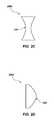
- FIG. 2A through FIG. 2Dare simplified schematics of marker particles in accordance with embodiments of the disclosure.
- Operating conditions within a subterranean formation and a wellboremay be determined by injecting marker particles into the subterranean formation and detecting the location and movement of the marker particles within the subterranean formation and the wellbore.
- reservoir propertiese.g., the location of producing zones, stimulated reservoir volumes, etc.
- stimulation treatmentse.g., stimulation, completion, production, etc.
- one or more types of marker particles configured to adhere between formation surfaces defining fractures or organic surfaces of the reservoirmay be injected into one or more regions of the subterranean formation and the location and movement of the marker particles may be monitored during well operation (e.g., stimulation, completion, production, etc.).
- Knowledge of the location and movement of the marker particles within the subterranean formationmay aid in determining particular zones within the subterranean formation from which produced fluids are recovered, the actual stimulated reservoir volume, and the effectiveness of the stimulation techniques (e.g., hydraulic fracturing).
- the length and width of conductive fractures formed during the fracturing processmay be determined by detecting the location and movement of marker particles in the fractures.
- Reservoir volumemay be determined by detecting the location of marker particles. As the marker particles move within the subterranean formation, the location of producing zones within the subterranean formation may be identified.
- movement of fluids within the reservoirmay be directed to different parts of the reservoir, by adjusting the volume and location of production and/or of the use of stimulation fluids.
- the real time monitoring of the location and movement of the marker particles within the subterranean formation and wellboremay provide information about the formation geometry, fracture geometry, fracturing effectiveness, reservoir volume, and producing zones.
- a plurality of transmitters within the wellboreis configured to transmit one or more signals within the subterranean formation.
- the one or more signalsmay include one or of an acoustic signal and an electromagnetic field.
- Each of the marker particlesmay be configured to exhibit one or more characteristics (e.g., an acoustic characteristic, an electrical conductivity characteristic, a magnetic characteristic, an electromagnetic characteristic, etc.) or configured to interact with the one or more signals (e.g., the acoustic signal, the electromagnetic field, etc.).
- the marker particlesmay interact with the one or more signals transmitted by the plurality of transmitters.
- the marker particlesmay be placed within a particular zone of the formation and then subsequently identified in a sample of produced fluid within the wellbore or at the surface, such as by measuring the electrical conductivity or magnetism of the produced fluid.
- At least a first portion of the marker particlesmay exhibit a first characteristic, at least a second portion of the marker particles exhibit a second characteristic, and at least a third portion of the marker particles may exhibit a third characteristic, etc.
- Each of the portions of the marker particlesmay be injected into different zones of the subterranean formation.
- Interaction of the marker particles with the one or more signals transmitted by the plurality of transmittersmay create at least one reflected signal that is received by at least one signal receiver of a plurality of signal receivers.
- the reflected signalsmay be detected and/or measured by the plurality of signal receivers.
- the detection of the signals by the plurality of signal receiversmay indicate at least one of the location and movement of the marker particles within the subterranean formation. Changes in the signals received by the plurality of receivers may indicate the location and movement of the marker particles within the wellbore and subterranean formation.
- first marker particlesare injected into the subterranean formation at a first zone.
- Second marker particlesmay be injected into the subterranean formation at a second zone.
- the first marker particles and the second marker particlesmay exhibit different characteristics (e.g., an acoustic characteristic, an electrical conductivity characteristic, a magnetic characteristic, an electromagnetic characteristic, etc.) than each other. If the first marker particles travel into the second zone, receivers of the plurality of receivers located within the second zone may identify such movement by a change in the signals (e.g., acoustic activity, electromagnetic field, etc.) received by the receivers.
- the receivers in the first zonemay also detect changing signals as the first marker particles move away from the first zone. If hydrocarbons from within the first zone are produced, a receiver in the wellbore or at the surface may identify the first marker particles within the produced fluid (e.g., by detecting an electrical conductance, a magnetism, etc., of the produced fluid).
- hydrocarbon recoverymay be enhanced by creating fractures in a subterranean formation containing hydrocarbons.
- Hydraulic or propellant-based fracturingmay create fractures in the subterranean formation in zones adjacent hydrocarbon-containing regions to create channels through which reservoir fluids may flow to the wellbore, through a production string, and to the surface.
- An hydraulic fracturing processmay include injecting a fracturing fluid (e.g., water, a high velocity propellant gas, etc.) into a wellbore at high pressures.
- the fracturing fluidmay be directed at a face of a hydrocarbon bearing subterranean formation.
- the high pressure fracturing fluidcreates fractures in the subterranean formation.
- Proppant mixed into fracturing fluidsmay be introduced (e.g., injected) into the formation to prop open the fluid channels created during the fracturing process at pressures below the pressure at which the fractures are created.
- the fractureswhen open, may provide a flow path for reservoir fluids (e.g., hydrocarbon-containing fluids) within the formation to flow from the formation to the production string and to the surface.
- the marker particlesinclude proppant particles mixed into and delivered to the subterranean formation through the fracturing fluid.
- the marker particlesmay be coated onto surfaces of proppant materials (e.g., sand, ceramics, particulates, etc.).
- proppant particles and marker particlesmay be preplaced in wellbore fluid adjacent a propellant-based stimulation tool, and driven into fractures created in the producing formation by high pressure gas generated by combustion of the propellant.
- Fracturing fluidsmay include water, water and potassium chloride solutions, carbonates such as sodium carbonate and potassium carbonate, gelled fluids, foamed gels, cross-linked gels, acids, ethylene glycol, and combinations thereof.
- Non-limiting examples of the fracturing fluidinclude gelled fluids such as materials including guar gum (e.g., hydroxypropylguar (HPG), carboxymethylhydroxypropylguar (CMHPG), hydroxyethyl cellulose (HEC) fluids), gels such as borate cross-linked fluids and borate salts, hydrochloric acid, formic acid, acetic acid, and combinations thereof.
- gelled fluidssuch as materials including guar gum (e.g., hydroxypropylguar (HPG), carboxymethylhydroxypropylguar (CMHPG), hydroxyethyl cellulose (HEC) fluids)
- gelssuch as borate cross-linked fluids and borate salts, hydrochloric acid, formic acid,
- the marker particlesinclude materials such as sand, ceramics, or other particulate materials.
- the marker particleswhen placed within the fractures, may prevent the fractures from closing, increasing the permeability of the formation and enhancing hydrocarbon recovery through the fractures.
- the marker particlesmay be removed from surfaces of the formation, and fractures previously held open by the marker particles may close, restricting the flow of reservoir fluids out of the reservoir and into the production string.
- the marker particlesmay mechanically fail (e.g., such as by being crushed) under closure stresses exerted by the formation after the fracturing pressure is withdrawn.
- the marker particlesmay detach from surfaces of the subterranean formation, from the fractures, from frac pack assemblies, and sidewalls of the wellbore and production tubing.
- the forces exerted by a produced fluid as the produced fluid travels by the marker particles attached within the wellboremay detach the marker particles from surfaces to which they are adhered. After detaching from such surfaces, the marker particles may be transported with the produced fluid flowing to the surface.
- flow back of the marker particlesmay reduce the production rates by closing the fractures between the reservoir and the production string and by clogging the wellbore and wellbore equipment.
- a change in production ratesmay be attributed to failure of the marker particles or movement of the marker particles from the fractures.
- specific zones within the subterranean formationmay be targeted for additional stimulation to restore production rates.
- the marker particlesmay be configured to adhere to surfaces of the subterranean formation, a frac pack assembly within the wellbore, sidewalls of the production tubing, and sidewalls of the wellbore. At least some of the marker particles may be configured to adhere to carbon-based materials, such as specific carbonate molecules (e.g., limestone) within the subterranean formation.
- the marker particlesmay be configured to adhere to organic surfaces within the subterranean formation.
- a mixture including the marker particlesis flowed through the subterranean formation and marker particles adhere to hydrocarbon bearing surfaces of the subterranean formation. The location of the adhered marker particles may aid in estimating a volume of hydrocarbons that may be produced from the formation.
- the marker particlesmay include proppants, nanoparticles, and combinations thereof.
- the term “nanoparticles”means and includes particles having an average particle size of less than about 1,000 nm.
- the marker particlesmay be introduced into the subterranean formation with fracturing fluids, with stimulation chemicals via chemical injection pumps, and combinations thereof.
- marker particles including proppants, nanoparticle markers, proppants coated with nanoparticle markers, and combinations thereofare introduced into the subterranean formation with fracturing fluids at the time of fracturing.
- the marker particlesmay have biomarkers configured to attach to organic surfaces of the formation.
- the marker particlesmay be configured to attach to hydrocarbon-containing surfaces of the subterranean formation.
- the marker particlesmay adhere to walls of the hydrocarbon-containing formation and the location of the marker materials may aid in determining the volume of the stimulated reservoir.
- the movement or presence of specific materials within the subterranean formationmay be detected with the marker particles.
- the marker particlesmay include molecules or functional groups configured to adhere to at least one of asphaltenes, alkanes, clays, and biological incrustation. Detection of marker particles configured to attach to a particular material (e.g., asphaltenes, alkanes, clays, biological incrustation) may be an indication of the location or movement of the particular material to which the marker particles are configured to attach.
- the subterranean formationmay include a plurality of zones, including a first zone 101 proximate a surface of the earth, an aquifer zone 102 between the first zone 101 and a hydrocarbon-containing zone 103 , a non-hydrocarbon-containing zone 104 , a first horizontal zone 105 , a second horizontal zone 106 , and a third horizontal zone 107 .
- a wellbore 110may extend through the subterranean formation and through each of the first zone 101 , the aquifer zone 102 , the hydrocarbon-containing zone 103 , the non-hydrocarbon-containing zone 104 , the first horizontal zone 105 , the second horizontal zone 106 , and the third horizontal zone 107 .
- Cement 112may line the wellbore 110 at least through the first zone 101 , the aquifer zone 102 , and a portion of the hydrocarbon-containing zone 103 .
- a liner string 113may line at least a portion of the wellbore 110 .
- a production string 114may extend through the subterranean formation and to a portion of the formation bearing hydrocarbons to be produced.
- the packers 108may include production packers, swellable packers, mechanical set packers, tension set packers, rotation set packers, hydraulic set packers, inflatable packers, or combinations thereof.
- the hydrocarbon-containing zone 103may be isolated from each of the aquifer zone 102 and the non-hydrocarbon-containing zone 104 by packers 108 .
- the second horizontal zone 106may be isolated from each of the first horizontal zone 105 and the third horizontal zone 107 by packers 108 .
- the hydrocarbon-containing zone 103may include a fracturing and gravel pack assembly 118 (e.g., a frac pack assembly). Gravel within the frac pack assembly 118 may filter sand and fines from the formation as produced fluids flow through the frac pack assembly 118 and into the production string 114 . In some embodiments, at least a portion of the marker particles may become entrained in the produced fluid may also become trapped within the frac pack assembly 118 , such as when the marker particles acting as proppants mechanically fail. Detection of the marker particles within the frac pack assembly 118 may indicate failure of the proppant marker particles. In some embodiments, a portion of marker particles (e.g., nanoparticles) that are smaller than proppant marker particles may pass through the frac pack assembly 118 while proppant marker particles are trapped within the frac pack assembly 118 .
- a fracturing and gravel pack assembly 118e.g., a frac pack assembly.
- the production string 114may include a communication device 120 extending from the surface of the formation along the production string 114 providing a means for communicating information to and from the surface of the formation.
- the communication device 120extends along an outer surface of the production string 114 .
- the communication device 120may include a fiber optic cable.
- the communication device 120includes a wired communication device, a radio communication device, an electromagnetic communication device, or a combination of such devices.
- the communication device 120may be installed at the time of placing the production string 114 within the wellbore 110 using methods and communication devices 120 as disclosed in, for example, U.S. Pat. No. 6,281,489 B1 to Tubel et al., which issued Aug. 28, 2001, the disclosure of which is hereby incorporated herein in its entirety by this reference.
- FIG. 1depicts the communication device 120 extending along an outer surface of the production string 114
- the communication device 120may be attached to an inner surface of the production string 114 , to the liner string 113 , and to combinations thereof.
- the communication device 120may be installed at the same time that the production string 114 or the liner string 113 are installed in the wellbore 110 .
- the communication device 120may be coupled to a source 122 , which may include a power source, a light source (e.g., for a fiber optics communications means 120 ), etc. Data from the communication device 120 may be sent to a data acquisition and processing unit 124 .
- a source 122which may include a power source, a light source (e.g., for a fiber optics communications means 120 ), etc.
- Data from the communication device 120may be sent to a data acquisition and processing unit 124 .
- a plurality of signal transmitters and a plurality of signal receiversmay be provided and in communication with the communication device 120 .
- the communication device 120may be attached to a plurality of transmitters 126 a , 126 b , 126 c , 126 d , 126 e , 126 f and a plurality of receivers 128 a , 128 b , 128 c , 128 d , 128 e , 128 f .
- Each of the plurality of transmitters 126 a , 126 b , 126 c , 126 d , 126 e , 126 f and each of the plurality of receivers 128 a , 128 b , 128 c , 128 d , 128 e , 128 fmay be permanently installed within the wellbore 110 .
- Each of the plurality of receivers 128 a , 128 b , 128 c , 128 d , 128 e , 128 fmay transmit data (e.g., signals received or detected) about conditions within the wellbore 110 to the data acquisition and processing unit 124 in real time.
- the transmitters 126 a , 126 b , 126 c , 126 d , 126 e , 126 f and receivers 128 a , 128 b , 128 c , 128 d , 128 e , 128 fmay be intermittently spaced within the wellbore 110 , such as at particular locations of interest within the wellbore 110 , or may be formed uniformly along the production string 114 , the liner string 113 , and combinations thereof.
- Each of the plurality of transmitters 126 a , 126 b , 126 c , 126 d , 126 e , 126 fmay be configured to generate and propagate at least one signal into the subterranean formation and wellbore 110 .
- the term “signal”means and includes a wave (e.g., an acoustic wave, electromagnetic energy, electromagnetic radiation, etc.), a field (e.g., an acoustic field, an electromagnetic field, etc.), a pulse (e.g., an acoustic pulse, an electromagnetic pulse (e.g., a short burst of electromagnetic energy), etc.).
- a wavee.g., an acoustic wave, electromagnetic energy, electromagnetic radiation, etc.
- a fielde.g., an acoustic field, an electromagnetic field, etc.
- a pulsee.g., an acoustic pulse, an electromagnetic pulse (e.g., a short burs
- each of the plurality of transmitters 126 a , 126 b , 126 c , 126 d , 126 e , 126 fmay be configured to generate at least one of an acoustic signal and an electromagnetic signal.
- the plurality of transmitters 126 a , 126 b , 126 c , 126 d , 126 e , 126 fis configured to transmit at least one of an acoustic field, and an electromagnetic field, and may also be configured to generate at least another of an acoustic field, and an electromagnetic field.
- At least some of the plurality of transmitters 126 a , 126 b , 126 c , 126 d , 126 e , and 126 fis configured such that an electric current flows from at least some of the plurality of transmitters 126 a , 126 b , 126 c , 126 d , 126 e , and 126 f to at least some other transmitters of the plurality of transmitters 126 a , 126 b , 126 c , 126 d , 126 e , and 126 f.
- Each of the plurality of receivers 128 a , 128 b , 128 c , 128 d , 128 e , 128 fmay be configured to receive and measure (e.g., detect) at least one type of signal of the signals generated and propagated by the plurality of transmitters 126 a , 126 b , 126 c , 126 d , 126 e , 126 f .
- the generated signalspropagate through the subterranean formation, fractures 116 , reservoir fluids, etc., a portion of the signals may be reflected, absorbed, or otherwise affected.
- Each of the plurality of receivers 128 a , 128 b , 128 c , 128 d , 128 e , 128 fmay be configured to measure at least one reflected signal. Accordingly, each of the plurality of receivers 128 a , 128 b , 128 c , 128 d , 128 e , 128 f may be configured to detect at least one of a reflected acoustic signal (e.g., a sound velocity, amplitude, frequency, etc.), and a reflected electromagnetic signal (e.g., an electromagnetic field).
- a reflected acoustic signale.g., a sound velocity, amplitude, frequency, etc.
- a reflected electromagnetic signale.g., an electromagnetic field
- Each of the plurality of receivers 128 a , 128 b , 128 c , 128 d , 128 e , 128 fmay detect the at least one reflected signal.
- each of the plurality of receivers 128 a , 128 b , 128 c , 128 d , 128 e , 128 fmay detect an acoustic characteristic, an electromagnetic field, and/or combinations thereof.
- the detected signalsmay be communicated through the communication device 120 to the data acquisition and processing unit 124 .
- Each of the receivers 128 a , 128 b , 128 c , 128 d , 128 e , 128 fmay be configured to measure several other conditions, such as temperature, pressure, flow rate, sand detection, phase measurement, oil-water content (e.g., water-cut), density, and/or seismic measurement, and to communicate such information to the data acquisition and processing unit 124 through the communication device 120 .
- the signals detected by the plurality of receivers 128 a , 128 b , 128 c , 128 d , 128 e , 128 fmay be recorded and logged over a period of time. In some embodiments, the signals are continuously logged in real time.
- Each section of the wellbore 110 within particular locations of the subterranean formationmay include at least one transmitter of the plurality of transmitters 126 a , 126 b , 126 c , 126 d , 126 e , 126 f and at least one receiver of the plurality of receivers 128 a , 128 b , 128 c , 128 d , 128 e , 128 f .
- a first plurality of signal transmitters and a first plurality of signal receiversare provided in a first zone of the subterranean formation and a second plurality of signal transmitters and a second plurality of signal receivers are provided in a second zone of the subterranean formation.
- At least one transmitter 126 a and at least one receiver 128 amay be located above the frac pack assembly 118 of the hydrocarbon-containing zone 103 (e.g., in the aquifer zone 102 ).
- the hydrocarbon-containing zone 103may include at least one transmitter 126 b and at least one receiver 128 b .
- the hydrocarbon-containing zone 103includes a transmitter 126 b and a receiver 128 b within the frac pack assembly 118 and at least another transmitter 126 b and another receiver 128 b outside the production string 114 .
- At least one transmitter 126 c and at least one receiver 128 cmay be located below the hydrocarbon-containing zone 103 , such as in the non-hydrocarbon-containing zone 104 .
- the first horizontal zone 105may include at least one transmitter 126 d and at least one receiver 128 d .
- the second horizontal zone 106may include at least one transmitter 126 e and at least one receiver 128 e .
- the third horizontal zone 107may include at least one transmitter 126 f and at least one receiver 128 f .
- an acoustic signal an electromagnetic field, and combinations thereofmay be measured in each zone (e.g., the first zone 101 and aquifer zone 102 , the hydrocarbon-containing zone 103 , the non-hydrocarbon-containing zone 104 , the first horizontal zone 105 , the second horizontal zone 106 , and the third horizontal zone 107 ) within the subterranean formation.
- each zonee.g., the first zone 101 and aquifer zone 102 , the hydrocarbon-containing zone 103 , the non-hydrocarbon-containing zone 104 , the first horizontal zone 105 , the second horizontal zone 106 , and the third horizontal zone 107 .
- the marker particlesmay be configured to be substantially electrically conductive or substantially electrically non-conductive (i.e., resistive), substantially magnetic or substantially non-magnetic, substantially electromagnetically active or substantially non-electromagnetically active, substantially acoustically conductive or substantially acoustically non-conductive, and combinations thereof.
- an “acoustically active” materialmeans and includes a material that transmits sound, such as by reflecting acoustic waves without substantially altering the properties (e.g., frequency, amplitude, velocity, etc.) of the acoustic waves of an acoustic field.
- an “acoustically non-active” materialmeans and includes a material that substantially absorbs (e.g., does not reflect) or otherwise interact with acoustic waves of an acoustic field and alter at least one property (e.g., frequency, amplitude, velocity, etc.) of the acoustic waves of the acoustic field.
- the term “electromagnetically non-active”means and includes a material that substantially alters an electromagnetic field.
- the term “electromagnetically active”means and includes a material that does not substantially alter an electromagnetic field and does not substantially interact with an electromagnetic field.
- the marker particlesmay be configured to interact (e.g., absorb, reflect, amplify, dampen, modify, etc.) with signals generated by the plurality of transmitters 126 a , 126 b , 126 c , 126 d , 126 e , 126 f .
- the movement of fluids within the wellbore system 100may be detected by tracking the location of the marker particles over a period of time.
- Signals generated by the plurality of transmitters 126 a , 126 b , 126 c , 126 d , 126 e , 126 fmay interact with the subterranean formation and the marker particles within the subterranean formation to form the signals detected by the plurality of receivers 128 a , 128 b , 128 c , 128 d , 128 e , 128 f .
- Interaction of the marker particles with the signals generated by the plurality of transmitters 126 a , 126 b , 126 c , 126 d , 126 e , 126 fmay create a unique signal detected by each of the plurality of receivers 128 a , 128 b , 128 c , 128 d , 128 e , 128 f
- the plurality of transmitters 126 a , 126 b , 126 c , 126 d , 126 e , 126 fmay generate a signal and the signal may be affected by the marker particles within the formation.
- Locations of the marker particlesmay be detected by receiving a signal reflected from the marker particles with at least one of the plurality of receivers 128 a , 128 b , 128 c , 128 d , 128 e , 128 f Movement of the marker particles may be determined by logging the locations of the marker particles over a period of time. For example, data about the signals received by the plurality of receivers 128 a , 128 b , 128 c , 128 d , 128 e , 128 f may be processed in the data acquisition and processing unit 124 in real time to determine the movement of the proppants within the subterranean formation and within the wellbore 110 .
- At least one of the acoustic field and the electromagnetic field within the subterranean formationis measured prior to injecting the marker particles into the subterranean formation.
- the received signalsmay correspond to a particular location of particular marker materials, such as a distance of each marker particle from the each of the plurality of receivers 128 a , 128 b , 128 c , 128 d , 128 e , and 128 f detecting the signal.
- an actual reservoir volume and an actual stimulated volumemay be estimated to estimate the effectiveness of stimulation techniques.
- At least a portion of the marker particlesmay be configured to have a distinct electric characteristic (e.g., electrical conductivity or electric resistivity), a distinct magnetic characteristic (e.g., magnetism), a distinct electromagnetic characteristic (e.g., electromagnetically active or electromagnetically non-active), and a distinct acoustic characteristic (e.g., acoustically active or acoustically non-active).
- a first portion of the marker particlesmay be coated with a material exhibiting a first acoustic activity, a first electric conductivity, a first magnetism, or a first electromagnetic characteristic.
- a second portion of the marker particlesmay be coated with another material exhibiting a second acoustic activity, a second electric conductivity, a second magnetism, or a second electromagnetic characteristic.
- a third portion of the marker particlesmay not be coated and may exhibit a third acoustic activity, a third electric conductivity, a third magnetism, or a third electromagnetic characteristic.
- the produced fluidmay be analyzed at the surface for the presence of at least some of the marker particles. For example, an electrical conductivity of the produced fluid, a magnetism of the produced fluid, and combinations thereof may be measured at the surface.
- a produced fluid with a distinct electrical conductivitymay be an indication that the produced fluids are produced from a particular zone in which marker particles with the distinct electrical conductivity were introduced.
- a hollow marker particle 200 a including a hollow central portion 202 defined by a solid outer shell 204is shown.
- the hollow marker particle 200 amay be configured to be substantially acoustically non-active.
- a solid marker particle 200 bis shown.
- the solid marker particle 200 bmay exhibit different acoustic characteristics than the hollow marker particle 200 a .
- the solid marker particle 200 bmay be configured be acoustically active.
- the solid marker particle 200 bmay be configured to reflect a greater percentage of acoustic waves back to the plurality of receivers 128 a , 128 b , 128 c , 128 d , 128 e , 128 f than the hollow marker particle 200 a .
- hollow marker particles 200 aare mixed with a fracturing fluid and pumped into the wellbore 110 and solid marker particles 200 b are mixed with another fracturing fluid and pumped into the wellbore 110 .
- the hollow marker particles 200 a and the solid marker particles 200 bmay be pumped into the same or different portions of the wellbore 110 .
- first marker particles having a first shapemay be injected into a first zone of the subterranean formation and second marker particles having a second shape may be injected into a second zone of the subterranean formation.
- concave marker particles 200 cmay include particles having at least one inwardly curved (e.g., rounded) surface 210 .
- convex marker particles 200 dmay include particles having at least one outwardly curved (e.g., rounded) surface 220 .
- concave marker particles 200 cmay be injected into the first zone and convex marker particles 200 d may be injected into the second zone.
- the concave marker particles 200 cmay reflect more or less acoustic waves than the convex marker particles 200 d .
- concave marker particles 200 cmay be configured to absorb more acoustic waves than convex marker particles 200 d .
- at least some of the marker particlesare convex and at least some of the proppant particles are concave.
- the marker particlesmay be surrounded by an encapsulant.
- the encapsulantmay be configured to release the marker particles at one of a predetermined exposure time within the subterranean formation, a predetermined temperature, a predetermined pressure, or a predetermined salinity.
- Encapsulated marker particles configured to release marker particles at a temperature, a pressure, or a salinity of a first zonemay be introduced into the formation and other encapsulated marker particles configured to release other marker particles at a temperature, a pressure, or a salinity of a second zone may be introduced into the second zone.
- a first portion of marker particlesmay be configured to be released at a first temperature
- a second portion of marker particlesmay be configured to be released at a second temperature
- a third portion of marker particlesmay be configured to be released at a third temperature
- movement of marker particles and fluids through a high salinity zonemay be monitored by introducing marker particles configured to be released at high salinity conditions (e.g., corresponding to the salinity of a targeted zone) and monitoring movement of the marker particles.
- marker particles at different locationsmay be monitored by introducing marker particles configured to be released at the temperatures, pressures, or salinities that correspond to the particular locations (e.g., depths) within the subterranean formation and monitoring movement of the marker particles.
- first marker particlesmay be placed within and adhere to a first portion of the subterranean formation
- second marker particlesmay be placed within and adhere to a second portion of the subterranean formation
- third marker particlesmay be placed within and adhere to a third portion of the subterranean formation.
- the first marker particlesmay be injected into the subterranean formation at the second horizontal zone 106 .
- the second marker particlesmay be injected into the subterranean formation within the hydrocarbon-containing zone 103 and may be configured to adhere to the subterranean formation within the fractures 116 .
- the third marker particlesmay be injected into the wellbore 110 and may be configured to attach to sand or gravel particles of the frac pack assembly 118 and on portions of the liner string 113 or production string 114 adjacent the frac pack assembly 118 .
- Each of the first marker particles, the second marker particles, and the third marker particlesmay interact differently with the signals generated by the plurality of transmitters 126 a , 126 b , 126 c , 126 d , 126 e , 126 f than each of the other of the first marker particles, the second marker particles, and the third marker particles.
- a reflected signal from each of the first marker particles, the second marker particles, and the third marker particlesmay exhibit a characteristic signal based on each of the marker particles.
- first marker particlesmay exhibit a first acoustic activity
- the second marker particlesmay exhibit a second acoustic activity
- the third marker particlesmay exhibit a third acoustic activity and each of the plurality of receivers 128 a , 128 b , 128 c , 128 d , 128 e , 128 f may measure a distinct acoustic signal based on the location of the first marker particles, the second marker particles, and the third marker particles.
- first marker particlesmay be electrically conductive and second marker particles may be electrically resistive.
- producing zonesmay be identified by measuring the electrical conductivity of the produced fluid at the surface and correlating the electrical conductivity to marker particles injected into particular producing zones.
- At least a portion of the marker particlesmay be configured to have a characteristic electrical conductivity, a characteristic magnetism, or configured to interact with at least one of an acoustic signal, and an electromagnetic field generated by the plurality of transmitters 126 a , 126 b , 126 c , 126 d , 126 e , 126 f and at least another portion of the marker particles may be configured to have a characteristic electrical conductivity, a characteristic magnetism, or configured to interact with another of the acoustic signal, and the electromagnetic field generated by the plurality of transmitters 126 a , 126 b , 126 c , 126 d , 126 e , 126 f .
- a first portion of marker particles configured to be acoustically activemay be introduced into a first zone of the subterranean formation and a second portion of marker particles configured to have a characteristic electrical conductivity, a characteristic magnetism, or configured to interact with an electromagnetic field may be introduced into a second zone of the subterranean formation.
- a first portion of marker particlesis pumped into a first zone of the subterranean formation
- a second portion of marker particlesis pumped into a second zone of the subterranean formation
- a third portion of marker particlesis pumped into a third zone of the subterranean formation.
- Each of the first portion of marker particles, the second portion of marker particles, and the third portion of marker particlesmay be configured to interact with different types of signals and/or exhibit different characteristics than the other of the first portion of marker particles, the second portion of marker particles, and the third portion of marker particles.
- any number of portions of market materials with different characteristics and interactions with signals generated by the plurality of transmitters 126 a , 126 b , 126 c , 126 d , 126 e , 126 fmay be used.
- the location of particular marker particlesmay be detected to determine operating parameters within the wellbore 110 .
- Each receiver of the plurality of receivers 128 a , 128 b , 128 c , 128 d , 128 e , 128 fmay be configured to receive information about the marker particles within the wellbore 110 , the fractures 116 , and the subterranean formation.
- the signals detected by each receivermay indicate the location of marker particles in the wellbore system 100 .
- Changes in the signals received by the plurality of receivers 128 a , 128 b , 128 c , 128 d , 128 e , 128 fmay indicate movement of fluids and marker particles within the wellbore system 100 .
- a first marker particle that is injected into the subterranean formation at a first zone of the subterranean formationmay exhibit different characteristics than a second marker particle injected into an adjacent zone. If the first marker particle travels into the adjacent zone of the subterranean formation, the receivers in the adjacent zone may identify such movement by a change in the signals (e.g., the acoustic activity, the electromagnetic field, etc.) received by the receivers in the second zone. The receivers in the first zone may also detect changing signals as the first marker particles move away from the first zone.
- the first marker particlesinclude hollow proppants.
- a receiver in the adjacent zone where the first marker particles are introducedmay receive a different acoustic signal (e.g., a weaker acoustic signal) when the first marker particles move into the adjacent zone.
- changes in acoustic activity or in an electromagnetic field measured by the receivers 128 a , 128 b , 128 c , 128 d , 128 e , 128 fmay be an indication of interactions between different sections within the wellbore 110 .
- An increasing acoustic activity, or an electromagnetic fieldmay be an indication that marker particles configured to increase such signals are moving toward the regions in which the increased signals are detected.
- a decreasing acoustic activity or electromagnetic fieldmay be an indication that marker particles configured to decrease such signals are moving away from the regions in which the decreasing signals are detected.
- an increase or decrease in the acoustic activity measured by a receivermay be an indication that acoustically active marker particles have respectively moved toward or away from the zone in which the receiver is located.
- a decrease in the electromagnetic field measured by a receiver in a zone where electromagnetically active marker particles have been placed within fractures 116may be an indication that the electromagnetically active marker particles within the fracture 116 are mechanically failing or moving out of the fractures 116 and exiting the wellbore 110 with the produced fluid.
- fractures 116 in a first zonemay be filled with first marker particles.
- the first marker particlesmay adhere to the subterranean formation within the fractures 116 .
- Fractures 116 in a second zonee.g., the second horizontal zone 106
- the second marker particlesmay adhere to the subterranean formation within the fractures 116 in the second zone.
- the first zone and the second zonemay each include hydrocarbons.
- the first marker particles and the second marker particlesare the same. In other embodiments, the first marker particles and the second marker particles are different.
- the first marker particlesmay be substantially electrically conductive and the second marker particles may be substantially electrically non-conductive (i.e., resistive).
- the first marker particlesmay be substantially magnetic and the second materials may be substantially non-magnetic.
- the first marker particlesmay be substantially acoustically active and the second marker particles may be substantially acoustically non-active.
- the first marker particlesare substantially electrically conductive or magnetic and the second marker particles are another of substantially electrically conductive or magnetic.
- Different horizontal zones of the subterranean formationmay include hydrocarbon-containing reservoirs.
- the subterranean formationmay be fractured in at least a first horizontal zone and a second horizontal zone.
- the first horizontal zonemay be fractured with a fracturing fluid including first marker particles and the second horizontal zone may be fractured with a fracturing fluid including second marker particles.
- the first marker particles and the second marker particlesmay be the same or may be different.
- Movement of the fluids from either of the first horizontal zone 105 or the second horizontal zone 106may be monitored by detecting changes in signals received by the plurality of receivers 128 a , 128 b , 128 c , 128 d , 128 e , 128 f as the marker particles interact with signals transmitted by the plurality of transmitters 126 a , 126 b , 126 c , 126 d , 126 e , 126 f.
- marker particlesmay be placed within the hydrocarbon-containing zone 103 .
- the marker particlesmay be substantially acoustically active, electrically conductive, magnetic, or electromagnetically active. A change in an electric conductivity, a magnetism, an acoustic activity, or an electromagnetic field measured by a receiver in the aquifer zone 102 or in the produced fluid at the surface may correspond to movement of materials from the hydrocarbon-containing zone 103 to the aquifer zone 102 .
- first marker particlesmay be injected into and adhere to the frac pack assembly 118 and second marker particles may be injected into fractures 116 of the subterranean formation surrounding the frac pack assembly 118 .
- the first marker particlesmay include hollow marker particles 200 a ( FIG. 2A ) and the second marker particles may include solid marker particles 200 b ( FIG. 2B ). Both of the hollow marker particles 200 a and the solid marker particles 200 b may be mixed with a fracturing fluid and injected into fractures 116 and into the frac pack assembly 118 at the same time.
- the hollow marker particles 200 amay be configured to mechanically fail under closure stresses exerted by the formation after the fracturing pressure is withdrawn.
- Measuring an acoustic activity characteristic of the hollow marker particles 200 a outside of the zone in which the frac pack assembly 118 is locatedmay be an indication of mechanical failure of the frac pack assembly 118 .
- Measuring an acoustic activity of the solid marker particles 200 bmay be an indication of movement of the solid marker particles 200 b and closure of the fractures 116 .
- An increasing concentration of marker particles in the frac pack assembly 118may be an indication of flow restrictions within the frac pack assembly 118 .
- the increasing concentration of marker particles in the frac pack assembly 118may be determined by measuring a field characteristic of the marker particles with receivers adjacent or within the frac pack assembly 118 . Corrective action may be taken responsive to the increasing concentration of marker particles in the frac pack assembly.
- a paraffin reducermay be pumped to the frac pack assembly 118 to break the paraffins (e.g., asphaltenes) that block flow channels within the frac pack assembly 118 .
- corrective actionsmay be taken responsive to movement of marker particles within the wellbore system 100 .
- corrective actionsmay include opening or closing sliding sleeves to increase or decrease production rates, remedial work such as cleaning or reaming operations, shutting down a particular zone, re-fracturing a particular zone, etc.
- additional marker particlese.g., proppants
- the subterranean formationmay be stimulated responsive to movement of the marker particles within the subterranean formation.
Landscapes
- Engineering & Computer Science (AREA)
- Mining & Mineral Resources (AREA)
- Geology (AREA)
- Life Sciences & Earth Sciences (AREA)
- Physics & Mathematics (AREA)
- Fluid Mechanics (AREA)
- Environmental & Geological Engineering (AREA)
- General Life Sciences & Earth Sciences (AREA)
- Geochemistry & Mineralogy (AREA)
- Geophysics (AREA)
- Acoustics & Sound (AREA)
- Mechanical Engineering (AREA)
- Geophysics And Detection Of Objects (AREA)
- Investigating Or Analyzing Materials By The Use Of Magnetic Means (AREA)
Abstract
Description
Claims (20)
Priority Applications (1)
| Application Number | Priority Date | Filing Date | Title |
|---|---|---|---|
| US14/826,614US10400584B2 (en) | 2014-08-15 | 2015-08-14 | Methods and systems for monitoring a subterranean formation and wellbore production |
Applications Claiming Priority (2)
| Application Number | Priority Date | Filing Date | Title |
|---|---|---|---|
| US201462038086P | 2014-08-15 | 2014-08-15 | |
| US14/826,614US10400584B2 (en) | 2014-08-15 | 2015-08-14 | Methods and systems for monitoring a subterranean formation and wellbore production |
Publications (2)
| Publication Number | Publication Date |
|---|---|
| US20160047232A1 US20160047232A1 (en) | 2016-02-18 |
| US10400584B2true US10400584B2 (en) | 2019-09-03 |
Family
ID=55301803
Family Applications (1)
| Application Number | Title | Priority Date | Filing Date |
|---|---|---|---|
| US14/826,614Active2036-10-11US10400584B2 (en) | 2014-08-15 | 2015-08-14 | Methods and systems for monitoring a subterranean formation and wellbore production |
Country Status (5)
| Country | Link |
|---|---|
| US (1) | US10400584B2 (en) |
| CA (1) | CA2957769C (en) |
| GB (1) | GB2544013B (en) |
| SA (1) | SA517380909B1 (en) |
| WO (1) | WO2016025828A1 (en) |
Cited By (4)
| Publication number | Priority date | Publication date | Assignee | Title |
|---|---|---|---|---|
| US11242743B2 (en) | 2019-06-21 | 2022-02-08 | Saudi Arabian Oil Company | Methods and systems to detect an untethered device at a wellhead |
| US20230025091A1 (en)* | 2019-12-10 | 2023-01-26 | Origin Rose Llc | Spectral analysis and machine learning for determining cluster efficiency during fracking operations |
| US11613691B1 (en)* | 2018-12-31 | 2023-03-28 | Oceanit Laboratories, Inc. | Well proppants |
| US11913329B1 (en) | 2022-09-21 | 2024-02-27 | Saudi Arabian Oil Company | Untethered logging devices and related methods of logging a wellbore |
Families Citing this family (8)
| Publication number | Priority date | Publication date | Assignee | Title |
|---|---|---|---|---|
| CN106677767B (en)* | 2016-12-12 | 2019-11-26 | 中国石油大学(华东) | A kind of casing leak source depth detection method and device for producing well |
| US11874418B2 (en)* | 2018-04-18 | 2024-01-16 | Borehole Seismic, Llc. | High resolution composite seismic imaging, systems and methods |
| WO2020013922A1 (en)* | 2018-07-12 | 2020-01-16 | Exxonmobil Upstream Research Company | Hydrocarbon wells and methods for identifying production from a region of a subterranean formation |
| WO2020091793A1 (en)* | 2018-11-01 | 2020-05-07 | Halliburton Energy Services, Inc. | Instrumented bridge plugs for downhole measurements |
| CA3066565A1 (en)* | 2019-01-04 | 2020-07-04 | Kobold Corporation | System and method for monitoring and controlling fluid flow |
| CN112324431B (en)* | 2020-09-27 | 2023-01-10 | 四川瑞都石油工程技术服务有限公司 | Multi-spectral-band high-resolution intelligent production test method for oil and gas well |
| CN114460136B (en)* | 2022-01-25 | 2024-10-29 | 湖南继善高科技有限公司 | Oil-gas fracturing monitoring electrical model building method and application method |
| US12152480B2 (en)* | 2022-06-19 | 2024-11-26 | Frac Science Group LLC | Real-time fracture volume measurements and predictions |
Citations (94)
| Publication number | Priority date | Publication date | Assignee | Title |
|---|---|---|---|---|
| US3828867A (en)* | 1972-05-15 | 1974-08-13 | A Elwood | Low frequency drill bit apparatus and method of locating the position of the drill head below the surface of the earth |
| US3916821A (en)* | 1972-06-19 | 1975-11-04 | Othmar W Pies | Magnetic marker assembly |
| US3990512A (en)* | 1975-07-10 | 1976-11-09 | Ultrasonic Energy Corporation | Method and system for ultrasonic oil recovery |
| US4237972A (en)* | 1979-01-15 | 1980-12-09 | Schlumberger Technology Corp. | Well bore apparatus adapted for being releasably coupled to suspension cables |
| US4442152A (en)* | 1982-06-01 | 1984-04-10 | Kirk Arthur G | Marker member |
| US4456067A (en)* | 1981-04-03 | 1984-06-26 | Marathon Oil Company | Process for inhibiting hydrate formation in producing gas wells |
| US4581927A (en)* | 1984-12-26 | 1986-04-15 | Marathon Oil Company | Self-contained bore hole flow measurement system and method therefor |
| US4712094A (en)* | 1986-05-29 | 1987-12-08 | Minnesota Mining And Manufacturing Company | Self-orienting passive marker structure |
| US4741401A (en)* | 1987-01-16 | 1988-05-03 | The Dow Chemical Company | Method for treating subterranean formations |
| US4752680A (en)* | 1984-11-20 | 1988-06-21 | Saab Automation Ab | Tags for identification system |
| US4919209A (en)* | 1989-01-17 | 1990-04-24 | Dowell Schlumberger Incorporated | Method for treating subterranean formations |
| US5025550A (en)* | 1990-05-25 | 1991-06-25 | Trovan Limited | Automated method for the manufacture of small implantable transponder devices |
| US5151658A (en) | 1989-12-29 | 1992-09-29 | Chinetsu Gijutsu Kaihatsu Kabushiki Kaisha | Three-dimensional detection system for detecting fractures and their distributions in the earth crust utilizing an artificial magnetic field and magnetic particle tracer |
| US5164099A (en)* | 1990-12-06 | 1992-11-17 | The Western Company Of North America | Encapsulations for treating subterranean formations and methods for the use thereof |
| US5200704A (en)* | 1991-02-28 | 1993-04-06 | Westinghouse Electric Corp. | System and method including a buried flexible sheet target impregnated with ferromagnetic particles and eddy current probe for determining proximity of a non-conductive underground structure |
| US5426716A (en)* | 1994-03-31 | 1995-06-20 | At&T Corp. | Magnetically locatable non-metallic optical fiber cables |
| US5485148A (en)* | 1993-03-31 | 1996-01-16 | Tseng; Ling-Yuan | Pipeline fluid travel monitoring system |
| US5532598A (en)* | 1994-05-25 | 1996-07-02 | Westinghouse Electric Corporation | Amorphous metal tagging system for underground structures including elongated particles of amorphous metal embedded in nonmagnetic and nonconductive material |
| US5585725A (en)* | 1995-04-13 | 1996-12-17 | Associated Universities, Inc. | Magnetic detection of underground pipe using timed-release marking droplets |
| US5620049A (en)* | 1995-12-14 | 1997-04-15 | Atlantic Richfield Company | Method for increasing the production of petroleum from a subterranean formation penetrated by a wellbore |
| US5635712A (en) | 1995-05-04 | 1997-06-03 | Halliburton Company | Method for monitoring the hydraulic fracturing of a subterranean formation |
| US5699048A (en)* | 1996-10-03 | 1997-12-16 | Industrial Technology Inc. | Omnidirectional passive electrical marker for underground use |
| US5884701A (en) | 1997-07-18 | 1999-03-23 | Schlumberger Technology Corpporation | Dual downhole injection system utilizing coiled tubing |
| US6097293A (en)* | 1999-04-15 | 2000-08-01 | Industrial Technology, Inc. | Passive electrical marker for underground use and method of making thereof |
| US6150986A (en)* | 1995-08-16 | 2000-11-21 | Alfa Laval Agri Ab | Antenna system comprising driver circuits for transponder |
| US6281489B1 (en) | 1997-05-02 | 2001-08-28 | Baker Hughes Incorporated | Monitoring of downhole parameters and tools utilizing fiber optics |
| US6333700B1 (en)* | 2000-03-28 | 2001-12-25 | Schlumberger Technology Corporation | Apparatus and method for downhole well equipment and process management, identification, and actuation |
| US6380857B1 (en)* | 2000-10-16 | 2002-04-30 | Industrial Technology, Inc. | Self leveling underground marker |
| EP1225302A2 (en)* | 2001-01-23 | 2002-07-24 | Halliburton Energy Services, Inc. | Well completion apparatus and method |
| US20020121374A1 (en) | 2001-03-01 | 2002-09-05 | Aaron Ranson | Method for heating subterranean formation, particularly for heating reservoir fluids in near well bore zone |
| US20020134587A1 (en)* | 2000-09-20 | 2002-09-26 | Stephen Rester | Method, system and tool for reservoir evaluation and well testing during drilling operations |
| US20020178805A1 (en)* | 2001-05-15 | 2002-12-05 | Baker Hughes Inc. | Method and apparatus for downhole fluid characterization using flexural mechanical resonators |
| US20030066645A1 (en)* | 2001-10-09 | 2003-04-10 | Armatage Russell J. | Method of and device for tracing hydraulic fractures, stimulations, cement jobs, etc. in oil and gas wells |
| US20030141064A1 (en)* | 2002-01-31 | 2003-07-31 | Roberson James David | Method and apparatus for fracing earth formations surrounding a wellbore |
| US20040069487A1 (en) | 2002-10-09 | 2004-04-15 | Schlumberger Technology Corporation | System and method for installation and use of devices in microboreholes |
| US6789043B1 (en)* | 1998-09-23 | 2004-09-07 | The Johns Hopkins University | Magnetic sensor system for fast-response, high resolution, high accuracy, three-dimensional position measurements |
| US20040227509A1 (en)* | 2003-02-28 | 2004-11-18 | Eisenmann Lacktechnik Kg | Position detector for a moving part in a pipe |
| US20050072570A1 (en)* | 2003-10-06 | 2005-04-07 | Lehman Lyle Vaughan | Contamination-resistant sand control apparatus and method for preventing contamination of sand control devices |
| US20050248460A1 (en)* | 2000-01-11 | 2005-11-10 | Ezequiel Mejia | Passive integrated transponder tag with unitary antenna core |
| US7073581B2 (en) | 2004-06-15 | 2006-07-11 | Halliburton Energy Services, Inc. | Electroconductive proppant compositions and related methods |
| US20070026968A1 (en)* | 2005-07-27 | 2007-02-01 | Ashley Ratcliffe | Transmitter tag |
| US20070039739A1 (en)* | 2003-07-30 | 2007-02-22 | Conocophillips Company | Well chemical treatment utilizing plunger lift delivery system with chemically improved plunger seal |
| WO2007093002A1 (en)* | 2006-02-16 | 2007-08-23 | Ecobuoy Pty Ltd | Sonar accessory & method |
| US20070205902A1 (en)* | 2006-03-03 | 2007-09-06 | Checkpoint Systems, Inc. | Rf release mechanism for hard tag |
| US20080061239A1 (en)* | 2006-09-12 | 2008-03-13 | Marta Levesque Bryan | Non-invasive active infrared triggering device to monitor amphibian and other animal life in aqueous environments |
| US20080069961A1 (en)* | 2006-09-14 | 2008-03-20 | Halliburton Energy Services, Inc. | Methods and compositions for thermally treating a conduit used for hydrocarbon production or transmission to help remove paraffin wax buildup |
| US20080111448A1 (en)* | 2005-01-14 | 2008-05-15 | John Darren Smith | Acoustic Reflector |
| US20080156484A1 (en)* | 2006-12-29 | 2008-07-03 | Ali Mese | Method and system for altering pore pressure in a fracturing operation |
| US20080245960A1 (en)* | 2007-04-09 | 2008-10-09 | Baker Hughes Incorporated | Method and Apparatus to Determine Characteristics of an Oil-Based Mud Downhole |
| US20080308270A1 (en)* | 2007-06-18 | 2008-12-18 | Conocophillips Company | Devices and Methods for Utilizing Pressure Variations as an Energy Source |
| US20080316049A1 (en)* | 2007-06-25 | 2008-12-25 | Turbo-Chem International, Inc. | RFID Tag Tracer Method and Apparatus |
| US20090032592A1 (en)* | 2006-01-11 | 2009-02-05 | Novo Nordisk A/S | Spherical encoded beads |
| US20090146381A1 (en)* | 2006-08-17 | 2009-06-11 | Herrera Derek F | Turbulent flow tool |
| US20090151939A1 (en)* | 2007-12-13 | 2009-06-18 | Schlumberger Technology Corporation | Surface tagging system with wired tubulars |
| US20090211754A1 (en)* | 2007-06-25 | 2009-08-27 | Turbo-Chem International, Inc. | WirelessTag Tracer Method and Apparatus |
| US20090224919A1 (en)* | 2008-03-06 | 2009-09-10 | Angell Robert L | Qualitative/Quantitative Analysis of a Material Using RFIDs |
| US20100051266A1 (en)* | 2007-04-02 | 2010-03-04 | Halliburton Energy Services, Inc. | Use of Micro-Electro-Mechanical Systems (MEMS) in Well Treatments |
| US20100181067A1 (en)* | 2009-01-16 | 2010-07-22 | Schlumberger Technology Corporation | Wireless power and telemetry transmission between connections of well completions |
| US20100243241A1 (en) | 2009-03-25 | 2010-09-30 | Occidental Chemical Corporation | Detecting Fluids In a Wellbore |
| US7836952B2 (en) | 2005-12-08 | 2010-11-23 | Halliburton Energy Services, Inc. | Proppant for use in a subterranean formation |
| US20110094754A1 (en)* | 2009-10-23 | 2011-04-28 | Gary Smart | Wellbore treatment apparatus and method |
| US20110108277A1 (en) | 2008-05-19 | 2011-05-12 | Halliburton Energy Services, Inc. | Formation Treatment Using Electromagnetic Radiation |
| US20110186290A1 (en)* | 2007-04-02 | 2011-08-04 | Halliburton Energy Services, Inc. | Use of Micro-Electro-Mechanical Systems (MEMS) in Well Treatments |
| US20110192594A1 (en)* | 2007-04-02 | 2011-08-11 | Halliburton Energy Services, Inc. | Use of Micro-Electro-Mechanical Systems (MEMS) in Well Treatments |
| US8010048B2 (en)* | 2005-01-20 | 2011-08-30 | Bae Systems Information And Electronic Systems Integration Inc. | Microradio design, manufacturing method and applications for the use of microradios |
| US8006755B2 (en) | 2008-08-15 | 2011-08-30 | Sun Drilling Products Corporation | Proppants coated by piezoelectric or magnetostrictive materials, or by mixtures or combinations thereof, to enable their tracking in a downhole environment |
| US20110215977A1 (en)* | 2010-03-05 | 2011-09-08 | Satworld Holding B.V. | Ball with positioning system |
| US20110265314A1 (en)* | 2006-01-20 | 2011-11-03 | Bae Systems Information And Electronic Systems Integration Inc. | Method of manufacturing a microradio |
| US20110269408A1 (en)* | 2005-01-20 | 2011-11-03 | Bae Systems Information And Electronic Systems Integration Inc. | Method of determining conditions on the ground using microradios |
| US20120037368A1 (en)* | 2010-08-12 | 2012-02-16 | Conocophillips Company | Controlled release proppant |
| US20120133526A1 (en)* | 2010-04-27 | 2012-05-31 | National Oilwell Varco, L.P. | Systems and methods for using wireless tags with downhole equipment |
| US20120181020A1 (en) | 2008-05-20 | 2012-07-19 | Oxane Materials, Inc. | Method Of Manufacture And The Use Of A Functional Proppant For Determination Of Subterranean Fracture Geometries |
| US8260201B2 (en)* | 2007-07-30 | 2012-09-04 | Bae Systems Information And Electronic Systems Integration Inc. | Dispersive antenna for RFID tags |
| US20120234537A1 (en) | 2010-09-14 | 2012-09-20 | Harris Corporation | Gravity drainage startup using rf & solvent |
| US20130017610A1 (en)* | 2011-07-12 | 2013-01-17 | Jeffery Roberts | Encapsulated tracers and chemicals for reservoir interrogation and manipulation |
| US20130025943A1 (en)* | 2011-07-28 | 2013-01-31 | Baker Hughes Incorporated | Apparatus and method for retrieval of downhole sample |
| US20130068940A1 (en)* | 2010-06-01 | 2013-03-21 | Halliburton Energy Services, Inc. | Spectroscopic nanosensor logging systems and methods |
| US20130075091A1 (en)* | 2010-05-31 | 2013-03-28 | Welltec A/S | Wellbore surveillance system |
| US20130213638A1 (en) | 2010-10-27 | 2013-08-22 | Stuart R. Keller | Methods of Using Nano-Particles In Wellbore Operations |
| US20130300571A1 (en)* | 2012-04-18 | 2013-11-14 | Farrokh Mohamadi | Interrogation of active and passive proppants for real-time monitoring of fractured wells |
| US20140054031A1 (en)* | 2011-03-04 | 2014-02-27 | Maersk Olie Og Gas A/S | Method and system for well and reservoir management in open hole completions as well as method and system for producing crude oil |
| US20140111349A1 (en)* | 2007-04-02 | 2014-04-24 | Halliburton Energy Services, Inc. | Methods and apparatus for evaluating downhole conditions with rfid mems sensors |
| US20140118156A1 (en)* | 2012-10-29 | 2014-05-01 | National Oilwell Varco, L.P. | System and method for using a passive wireless tag |
| US8720547B2 (en) | 2008-09-26 | 2014-05-13 | Conocophillips Company | Process for enhanced production of heavy oil using microwaves |
| US20140174724A1 (en)* | 2012-12-21 | 2014-06-26 | Halliburton Energy Services, Inc. | Hollow hydrogel capsules and methods of using the same |
| US20150075776A1 (en)* | 2013-07-24 | 2015-03-19 | D. Jack Adams | Optimization of biogenic methane production from hydrocarbon sources |
| US20160194546A1 (en)* | 2015-01-05 | 2016-07-07 | Chevron U.S.A. Inc. | Methods of fluid loss control |
| US20160320769A1 (en)* | 2015-04-30 | 2016-11-03 | Aramco Services Company | Method and device for obtaining measurements of downhole properties in a subterranean well |
| US20170101572A1 (en)* | 2014-06-02 | 2017-04-13 | Schlumberger Technology Corporation | Degradation agent encapsulation |
| US20180044570A1 (en)* | 2016-08-15 | 2018-02-15 | Battelle Memorial Institute | Self-repairing cement polymer composites and processes of making and using same |
| US20180258337A1 (en)* | 2017-03-07 | 2018-09-13 | Saudi Arabian Oil Company | Method of Encapsulating Signaling Agents For Use Downhole |
| US20180258336A1 (en)* | 2017-03-07 | 2018-09-13 | Saudi Arabian Oil Company | Wellbore Cement Having Spent Polymer Capsule Shells |
| US20190062620A1 (en)* | 2017-08-28 | 2019-02-28 | Ambrish Kamdar | Method for Time-Controlled Release of Breakers by Use of Breakers Encapsulated Within Membranes Containing Water Soluble Polymers |
| US20190077989A1 (en)* | 2004-12-29 | 2019-03-14 | Troxler Electronic Laboratories, Inc. | Asphalt release agent |
- 2015
- 2015-08-14GBGB1703545.2Apatent/GB2544013B/ennot_activeExpired - Fee Related
- 2015-08-14USUS14/826,614patent/US10400584B2/enactiveActive
- 2015-08-14WOPCT/US2015/045267patent/WO2016025828A1/enactiveApplication Filing
- 2015-08-14CACA2957769Apatent/CA2957769C/enactiveActive
- 2017
- 2017-02-15SASA517380909Apatent/SA517380909B1/enunknown
Patent Citations (96)
| Publication number | Priority date | Publication date | Assignee | Title |
|---|---|---|---|---|
| US3828867A (en)* | 1972-05-15 | 1974-08-13 | A Elwood | Low frequency drill bit apparatus and method of locating the position of the drill head below the surface of the earth |
| US3916821A (en)* | 1972-06-19 | 1975-11-04 | Othmar W Pies | Magnetic marker assembly |
| US3990512A (en)* | 1975-07-10 | 1976-11-09 | Ultrasonic Energy Corporation | Method and system for ultrasonic oil recovery |
| US4237972A (en)* | 1979-01-15 | 1980-12-09 | Schlumberger Technology Corp. | Well bore apparatus adapted for being releasably coupled to suspension cables |
| US4456067A (en)* | 1981-04-03 | 1984-06-26 | Marathon Oil Company | Process for inhibiting hydrate formation in producing gas wells |
| US4442152A (en)* | 1982-06-01 | 1984-04-10 | Kirk Arthur G | Marker member |
| US4752680A (en)* | 1984-11-20 | 1988-06-21 | Saab Automation Ab | Tags for identification system |
| US4581927A (en)* | 1984-12-26 | 1986-04-15 | Marathon Oil Company | Self-contained bore hole flow measurement system and method therefor |
| US4712094A (en)* | 1986-05-29 | 1987-12-08 | Minnesota Mining And Manufacturing Company | Self-orienting passive marker structure |
| US4741401A (en)* | 1987-01-16 | 1988-05-03 | The Dow Chemical Company | Method for treating subterranean formations |
| US4919209A (en)* | 1989-01-17 | 1990-04-24 | Dowell Schlumberger Incorporated | Method for treating subterranean formations |
| US5151658A (en) | 1989-12-29 | 1992-09-29 | Chinetsu Gijutsu Kaihatsu Kabushiki Kaisha | Three-dimensional detection system for detecting fractures and their distributions in the earth crust utilizing an artificial magnetic field and magnetic particle tracer |
| US5025550A (en)* | 1990-05-25 | 1991-06-25 | Trovan Limited | Automated method for the manufacture of small implantable transponder devices |
| US5164099A (en)* | 1990-12-06 | 1992-11-17 | The Western Company Of North America | Encapsulations for treating subterranean formations and methods for the use thereof |
| US5200704A (en)* | 1991-02-28 | 1993-04-06 | Westinghouse Electric Corp. | System and method including a buried flexible sheet target impregnated with ferromagnetic particles and eddy current probe for determining proximity of a non-conductive underground structure |
| US5485148A (en)* | 1993-03-31 | 1996-01-16 | Tseng; Ling-Yuan | Pipeline fluid travel monitoring system |
| US5426716A (en)* | 1994-03-31 | 1995-06-20 | At&T Corp. | Magnetically locatable non-metallic optical fiber cables |
| US5532598A (en)* | 1994-05-25 | 1996-07-02 | Westinghouse Electric Corporation | Amorphous metal tagging system for underground structures including elongated particles of amorphous metal embedded in nonmagnetic and nonconductive material |
| US5585725A (en)* | 1995-04-13 | 1996-12-17 | Associated Universities, Inc. | Magnetic detection of underground pipe using timed-release marking droplets |
| US5635712A (en) | 1995-05-04 | 1997-06-03 | Halliburton Company | Method for monitoring the hydraulic fracturing of a subterranean formation |
| US6150986A (en)* | 1995-08-16 | 2000-11-21 | Alfa Laval Agri Ab | Antenna system comprising driver circuits for transponder |
| US5620049A (en)* | 1995-12-14 | 1997-04-15 | Atlantic Richfield Company | Method for increasing the production of petroleum from a subterranean formation penetrated by a wellbore |
| US5699048A (en)* | 1996-10-03 | 1997-12-16 | Industrial Technology Inc. | Omnidirectional passive electrical marker for underground use |
| US6281489B1 (en) | 1997-05-02 | 2001-08-28 | Baker Hughes Incorporated | Monitoring of downhole parameters and tools utilizing fiber optics |
| US5884701A (en) | 1997-07-18 | 1999-03-23 | Schlumberger Technology Corpporation | Dual downhole injection system utilizing coiled tubing |
| US6789043B1 (en)* | 1998-09-23 | 2004-09-07 | The Johns Hopkins University | Magnetic sensor system for fast-response, high resolution, high accuracy, three-dimensional position measurements |
| US6097293A (en)* | 1999-04-15 | 2000-08-01 | Industrial Technology, Inc. | Passive electrical marker for underground use and method of making thereof |
| US20050248460A1 (en)* | 2000-01-11 | 2005-11-10 | Ezequiel Mejia | Passive integrated transponder tag with unitary antenna core |
| US6333700B1 (en)* | 2000-03-28 | 2001-12-25 | Schlumberger Technology Corporation | Apparatus and method for downhole well equipment and process management, identification, and actuation |
| US20020134587A1 (en)* | 2000-09-20 | 2002-09-26 | Stephen Rester | Method, system and tool for reservoir evaluation and well testing during drilling operations |
| US6380857B1 (en)* | 2000-10-16 | 2002-04-30 | Industrial Technology, Inc. | Self leveling underground marker |
| EP1225302A2 (en)* | 2001-01-23 | 2002-07-24 | Halliburton Energy Services, Inc. | Well completion apparatus and method |
| US20020121374A1 (en) | 2001-03-01 | 2002-09-05 | Aaron Ranson | Method for heating subterranean formation, particularly for heating reservoir fluids in near well bore zone |
| US20020178805A1 (en)* | 2001-05-15 | 2002-12-05 | Baker Hughes Inc. | Method and apparatus for downhole fluid characterization using flexural mechanical resonators |
| US20030066645A1 (en)* | 2001-10-09 | 2003-04-10 | Armatage Russell J. | Method of and device for tracing hydraulic fractures, stimulations, cement jobs, etc. in oil and gas wells |
| US20030141064A1 (en)* | 2002-01-31 | 2003-07-31 | Roberson James David | Method and apparatus for fracing earth formations surrounding a wellbore |
| US20040069487A1 (en) | 2002-10-09 | 2004-04-15 | Schlumberger Technology Corporation | System and method for installation and use of devices in microboreholes |
| US20040227509A1 (en)* | 2003-02-28 | 2004-11-18 | Eisenmann Lacktechnik Kg | Position detector for a moving part in a pipe |
| US20070039739A1 (en)* | 2003-07-30 | 2007-02-22 | Conocophillips Company | Well chemical treatment utilizing plunger lift delivery system with chemically improved plunger seal |
| US20050072570A1 (en)* | 2003-10-06 | 2005-04-07 | Lehman Lyle Vaughan | Contamination-resistant sand control apparatus and method for preventing contamination of sand control devices |
| US7073581B2 (en) | 2004-06-15 | 2006-07-11 | Halliburton Energy Services, Inc. | Electroconductive proppant compositions and related methods |
| US20190077989A1 (en)* | 2004-12-29 | 2019-03-14 | Troxler Electronic Laboratories, Inc. | Asphalt release agent |
| US20080111448A1 (en)* | 2005-01-14 | 2008-05-15 | John Darren Smith | Acoustic Reflector |
| US20110269408A1 (en)* | 2005-01-20 | 2011-11-03 | Bae Systems Information And Electronic Systems Integration Inc. | Method of determining conditions on the ground using microradios |
| US8010048B2 (en)* | 2005-01-20 | 2011-08-30 | Bae Systems Information And Electronic Systems Integration Inc. | Microradio design, manufacturing method and applications for the use of microradios |
| US20070026968A1 (en)* | 2005-07-27 | 2007-02-01 | Ashley Ratcliffe | Transmitter tag |
| US7836952B2 (en) | 2005-12-08 | 2010-11-23 | Halliburton Energy Services, Inc. | Proppant for use in a subterranean formation |
| US20090032592A1 (en)* | 2006-01-11 | 2009-02-05 | Novo Nordisk A/S | Spherical encoded beads |
| US20110265314A1 (en)* | 2006-01-20 | 2011-11-03 | Bae Systems Information And Electronic Systems Integration Inc. | Method of manufacturing a microradio |
| WO2007093002A1 (en)* | 2006-02-16 | 2007-08-23 | Ecobuoy Pty Ltd | Sonar accessory & method |
| US20070205902A1 (en)* | 2006-03-03 | 2007-09-06 | Checkpoint Systems, Inc. | Rf release mechanism for hard tag |
| US20090146381A1 (en)* | 2006-08-17 | 2009-06-11 | Herrera Derek F | Turbulent flow tool |
| US20080061239A1 (en)* | 2006-09-12 | 2008-03-13 | Marta Levesque Bryan | Non-invasive active infrared triggering device to monitor amphibian and other animal life in aqueous environments |
| US20080069961A1 (en)* | 2006-09-14 | 2008-03-20 | Halliburton Energy Services, Inc. | Methods and compositions for thermally treating a conduit used for hydrocarbon production or transmission to help remove paraffin wax buildup |
| US20080156484A1 (en)* | 2006-12-29 | 2008-07-03 | Ali Mese | Method and system for altering pore pressure in a fracturing operation |
| US20140111349A1 (en)* | 2007-04-02 | 2014-04-24 | Halliburton Energy Services, Inc. | Methods and apparatus for evaluating downhole conditions with rfid mems sensors |
| US20110192594A1 (en)* | 2007-04-02 | 2011-08-11 | Halliburton Energy Services, Inc. | Use of Micro-Electro-Mechanical Systems (MEMS) in Well Treatments |
| US20100051266A1 (en)* | 2007-04-02 | 2010-03-04 | Halliburton Energy Services, Inc. | Use of Micro-Electro-Mechanical Systems (MEMS) in Well Treatments |
| US20110186290A1 (en)* | 2007-04-02 | 2011-08-04 | Halliburton Energy Services, Inc. | Use of Micro-Electro-Mechanical Systems (MEMS) in Well Treatments |
| US20080245960A1 (en)* | 2007-04-09 | 2008-10-09 | Baker Hughes Incorporated | Method and Apparatus to Determine Characteristics of an Oil-Based Mud Downhole |
| US20080308270A1 (en)* | 2007-06-18 | 2008-12-18 | Conocophillips Company | Devices and Methods for Utilizing Pressure Variations as an Energy Source |
| US20090211754A1 (en)* | 2007-06-25 | 2009-08-27 | Turbo-Chem International, Inc. | WirelessTag Tracer Method and Apparatus |
| US20080316049A1 (en)* | 2007-06-25 | 2008-12-25 | Turbo-Chem International, Inc. | RFID Tag Tracer Method and Apparatus |
| US8260201B2 (en)* | 2007-07-30 | 2012-09-04 | Bae Systems Information And Electronic Systems Integration Inc. | Dispersive antenna for RFID tags |
| US20100044034A1 (en)* | 2007-12-13 | 2010-02-25 | Louise Bailey | Subsurface tagging system with wired tubulars |
| US20090151939A1 (en)* | 2007-12-13 | 2009-06-18 | Schlumberger Technology Corporation | Surface tagging system with wired tubulars |
| US20090224919A1 (en)* | 2008-03-06 | 2009-09-10 | Angell Robert L | Qualitative/Quantitative Analysis of a Material Using RFIDs |
| US20110108277A1 (en) | 2008-05-19 | 2011-05-12 | Halliburton Energy Services, Inc. | Formation Treatment Using Electromagnetic Radiation |
| US20120181020A1 (en) | 2008-05-20 | 2012-07-19 | Oxane Materials, Inc. | Method Of Manufacture And The Use Of A Functional Proppant For Determination Of Subterranean Fracture Geometries |
| US8006755B2 (en) | 2008-08-15 | 2011-08-30 | Sun Drilling Products Corporation | Proppants coated by piezoelectric or magnetostrictive materials, or by mixtures or combinations thereof, to enable their tracking in a downhole environment |
| US8720547B2 (en) | 2008-09-26 | 2014-05-13 | Conocophillips Company | Process for enhanced production of heavy oil using microwaves |
| US20100181067A1 (en)* | 2009-01-16 | 2010-07-22 | Schlumberger Technology Corporation | Wireless power and telemetry transmission between connections of well completions |
| US20100243241A1 (en) | 2009-03-25 | 2010-09-30 | Occidental Chemical Corporation | Detecting Fluids In a Wellbore |
| US20110094754A1 (en)* | 2009-10-23 | 2011-04-28 | Gary Smart | Wellbore treatment apparatus and method |
| US20110215977A1 (en)* | 2010-03-05 | 2011-09-08 | Satworld Holding B.V. | Ball with positioning system |
| US20120133526A1 (en)* | 2010-04-27 | 2012-05-31 | National Oilwell Varco, L.P. | Systems and methods for using wireless tags with downhole equipment |
| US20130075091A1 (en)* | 2010-05-31 | 2013-03-28 | Welltec A/S | Wellbore surveillance system |
| US20130068940A1 (en)* | 2010-06-01 | 2013-03-21 | Halliburton Energy Services, Inc. | Spectroscopic nanosensor logging systems and methods |
| US20120037368A1 (en)* | 2010-08-12 | 2012-02-16 | Conocophillips Company | Controlled release proppant |
| US20120234537A1 (en) | 2010-09-14 | 2012-09-20 | Harris Corporation | Gravity drainage startup using rf & solvent |
| US20130213638A1 (en) | 2010-10-27 | 2013-08-22 | Stuart R. Keller | Methods of Using Nano-Particles In Wellbore Operations |
| US20140054031A1 (en)* | 2011-03-04 | 2014-02-27 | Maersk Olie Og Gas A/S | Method and system for well and reservoir management in open hole completions as well as method and system for producing crude oil |
| US20130017610A1 (en)* | 2011-07-12 | 2013-01-17 | Jeffery Roberts | Encapsulated tracers and chemicals for reservoir interrogation and manipulation |
| US20130025943A1 (en)* | 2011-07-28 | 2013-01-31 | Baker Hughes Incorporated | Apparatus and method for retrieval of downhole sample |
| US20130300571A1 (en)* | 2012-04-18 | 2013-11-14 | Farrokh Mohamadi | Interrogation of active and passive proppants for real-time monitoring of fractured wells |
| US20140118156A1 (en)* | 2012-10-29 | 2014-05-01 | National Oilwell Varco, L.P. | System and method for using a passive wireless tag |
| US20140174724A1 (en)* | 2012-12-21 | 2014-06-26 | Halliburton Energy Services, Inc. | Hollow hydrogel capsules and methods of using the same |
| US20150075776A1 (en)* | 2013-07-24 | 2015-03-19 | D. Jack Adams | Optimization of biogenic methane production from hydrocarbon sources |
| US20170101572A1 (en)* | 2014-06-02 | 2017-04-13 | Schlumberger Technology Corporation | Degradation agent encapsulation |
| US20160194546A1 (en)* | 2015-01-05 | 2016-07-07 | Chevron U.S.A. Inc. | Methods of fluid loss control |
| US20160320769A1 (en)* | 2015-04-30 | 2016-11-03 | Aramco Services Company | Method and device for obtaining measurements of downhole properties in a subterranean well |
| US20180044570A1 (en)* | 2016-08-15 | 2018-02-15 | Battelle Memorial Institute | Self-repairing cement polymer composites and processes of making and using same |
| US20180258337A1 (en)* | 2017-03-07 | 2018-09-13 | Saudi Arabian Oil Company | Method of Encapsulating Signaling Agents For Use Downhole |
| US20180258336A1 (en)* | 2017-03-07 | 2018-09-13 | Saudi Arabian Oil Company | Wellbore Cement Having Spent Polymer Capsule Shells |
| US20180362828A1 (en)* | 2017-03-07 | 2018-12-20 | Saudi Arabian Oil Company | Method of encapsulating signaling agents for use downhole |
| US20190062620A1 (en)* | 2017-08-28 | 2019-02-28 | Ambrish Kamdar | Method for Time-Controlled Release of Breakers by Use of Breakers Encapsulated Within Membranes Containing Water Soluble Polymers |
Non-Patent Citations (8)
| Title |
|---|
| Basu et al., A New Method for Fracture Diagnostics Using Low Frequency Electromagnetic Induction, University of Texas, Fracturing and Sand Control JIP, Annual Meeting, (2014), 54 pages. |
| Canadian Office Action for CA Application No. 2957769 dated Dec. 18, 2017, 5 pages. |
| Elshahawi, Hani, et al. "Fluid fingerprinting-a real-time analysis tool for deep water." Hart's E & P 84.7 (2011): 50-51. (Year: 2011).* |
| Elshahawi, Hani, et al. "Fluid fingerprinting—a real-time analysis tool for deep water." Hart's E & P 84.7 (2011): 50-51. (Year: 2011).* |
| International Search Report for International Application No. PCT.US2015/045267 dated Oct. 20, 2015, 3 pages. |
| International Search Report for International Application No. PCT/US2015/041107 dated Apr. 1, 2016, 3 pages. |
| International Written Opinion for International Application No. PCT.US2015/045267 dated Oct. 20, 2015, 8 pages. |
| International Written Opinion for International Application No. PCT/US2015/041107 dated Apr. 1, 2016, 7 pages. |
Cited By (8)
| Publication number | Priority date | Publication date | Assignee | Title |
|---|---|---|---|---|
| US11613691B1 (en)* | 2018-12-31 | 2023-03-28 | Oceanit Laboratories, Inc. | Well proppants |
| US11242743B2 (en) | 2019-06-21 | 2022-02-08 | Saudi Arabian Oil Company | Methods and systems to detect an untethered device at a wellhead |
| US11697990B2 (en) | 2019-06-21 | 2023-07-11 | Saudi Arabian Oil Company | Methods and systems to detect an untethered device at a wellhead |
| US20230025091A1 (en)* | 2019-12-10 | 2023-01-26 | Origin Rose Llc | Spectral analysis and machine learning for determining cluster efficiency during fracking operations |
| US11740377B2 (en)* | 2019-12-10 | 2023-08-29 | Origin Rose Llc | Spectral analysis and machine learning for determining cluster efficiency during fracking operations |
| US12287444B2 (en) | 2019-12-10 | 2025-04-29 | Momentum AI, LLC | Spectral analysis, machine learning, and frac score assignment to acoustic signatures of fracking events |
| US12292539B2 (en) | 2019-12-10 | 2025-05-06 | Momentum AI, LLC | Spectral analysis and machine learning for determining cluster efficiency during fracking operations |
| US11913329B1 (en) | 2022-09-21 | 2024-02-27 | Saudi Arabian Oil Company | Untethered logging devices and related methods of logging a wellbore |
Also Published As
| Publication number | Publication date |
|---|---|
| CA2957769A1 (en) | 2016-02-18 |
| SA517380909B1 (en) | 2022-05-12 |
| WO2016025828A1 (en) | 2016-02-18 |
| US20160047232A1 (en) | 2016-02-18 |
| CA2957769C (en) | 2020-07-07 |
| GB2544013B (en) | 2019-03-27 |
| GB2544013A (en) | 2017-05-03 |
| GB201703545D0 (en) | 2017-04-19 |
Similar Documents
| Publication | Publication Date | Title |
|---|---|---|
| US10400584B2 (en) | Methods and systems for monitoring a subterranean formation and wellbore production | |
| US10253598B2 (en) | Diagnostic lateral wellbores and methods of use | |
| US20180283153A1 (en) | Methods and materials for evaluating and improving the production of geo-specific shale reservoirs | |
| US9822626B2 (en) | Planning and performing re-fracturing operations based on microseismic monitoring | |
| US6408943B1 (en) | Method and apparatus for placing and interrogating downhole sensors | |
| CN103299031B (en) | Multi-Stage Fracture Injection Approach for Improving Production of Shale Resources | |
| Dohmen et al. | Microseismic magnitudes and b-values for delineating hydraulic fracturing and depletion | |
| US9670770B2 (en) | Fracture evaluation through cased boreholes | |
| US20170247995A1 (en) | Evaluating far field fracture complexity and optimizing fracture design in multi-well pad development | |
| US10126448B2 (en) | Formation measurements using downhole noise sources | |
| AU2022201376A1 (en) | Methods and systems for monitoring and optimizing reservoir stimulation operations | |
| EP2661537B1 (en) | Fracture detection via self-potential methods with an electrically reactive proppant | |
| WO2017035370A1 (en) | Methods and materials for evaluating and improving the production of geo-specific shale reservoirs | |
| US9133699B2 (en) | Electrical methods fracture detection via 4D techniques | |
| Temizel et al. | A review of hydraulic fracturing and latest developments in unconventional reservoirs | |
| US11319790B2 (en) | Proppant ramp up decision making | |
| US20170138182A1 (en) | Moving system and method | |
| WO2018208579A1 (en) | Evaluating far field fracture complexity and optimizing fracture design in multi-well pad development | |
| Mulhim et al. | First successful proppant fracture for unconventional carbonate source rock in Saudi Arabia | |
| US11725507B2 (en) | Generating tube waves within a wellbore using an electrohydraulic discharge source | |
| US20120199345A1 (en) | Unconventional Gas Fracture Logging Method and Apparatus |
Legal Events
| Date | Code | Title | Description |
|---|---|---|---|
| AS | Assignment | Owner name:BAKER HUGHES INCORPORATED, TEXAS Free format text:ASSIGNMENT OF ASSIGNORS INTEREST;ASSIGNOR:PALOMAREZ, VINCENT;REEL/FRAME:045397/0794 Effective date:20140916 Owner name:BAKER HUGHES, A GE COMPANY, LLC, TEXAS Free format text:ENTITY CONVERSION;ASSIGNOR:BAKER HUGHES INCORPORATED;REEL/FRAME:045789/0102 Effective date:20170703 | |
| STCV | Information on status: appeal procedure | Free format text:NOTICE OF APPEAL FILED | |
| STPP | Information on status: patent application and granting procedure in general | Free format text:NOTICE OF ALLOWANCE MAILED -- APPLICATION RECEIVED IN OFFICE OF PUBLICATIONS | |
| STPP | Information on status: patent application and granting procedure in general | Free format text:AWAITING TC RESP, ISSUE FEE PAYMENT VERIFIED | |
| STPP | Information on status: patent application and granting procedure in general | Free format text:PUBLICATIONS -- ISSUE FEE PAYMENT VERIFIED | |
| STCF | Information on status: patent grant | Free format text:PATENTED CASE | |
| CC | Certificate of correction | ||
| AS | Assignment | Owner name:BAKER HUGHES HOLDINGS LLC, TEXAS Free format text:CHANGE OF NAME;ASSIGNOR:BAKER HUGHES, A GE COMPANY, LLC;REEL/FRAME:060791/0629 Effective date:20200415 | |
| MAFP | Maintenance fee payment | Free format text:PAYMENT OF MAINTENANCE FEE, 4TH YEAR, LARGE ENTITY (ORIGINAL EVENT CODE: M1551); ENTITY STATUS OF PATENT OWNER: LARGE ENTITY Year of fee payment:4 |