US10398880B2 - Medical systems, devices, and related methods - Google Patents
Medical systems, devices, and related methodsDownload PDFInfo
- Publication number
- US10398880B2 US10398880B2US16/178,163US201816178163AUS10398880B2US 10398880 B2US10398880 B2US 10398880B2US 201816178163 AUS201816178163 AUS 201816178163AUS 10398880 B2US10398880 B2US 10398880B2
- Authority
- US
- United States
- Prior art keywords
- balloon
- lumen
- artery
- internal carotid
- carotid artery
- Prior art date
- Legal status (The legal status is an assumption and is not a legal conclusion. Google has not performed a legal analysis and makes no representation as to the accuracy of the status listed.)
- Active
Links
- UZNXDMJDHVHXPJ-KOYOXNRPSA-NC[C@@H]1C(CC2SC22)C22C1CC2Chemical compoundC[C@@H]1C(CC2SC22)C22C1CC2UZNXDMJDHVHXPJ-KOYOXNRPSA-N0.000description1
Images


Classifications
- A—HUMAN NECESSITIES
- A61—MEDICAL OR VETERINARY SCIENCE; HYGIENE
- A61B—DIAGNOSIS; SURGERY; IDENTIFICATION
- A61B17/00—Surgical instruments, devices or methods
- A61B17/12—Surgical instruments, devices or methods for ligaturing or otherwise compressing tubular parts of the body, e.g. blood vessels or umbilical cord
- A61B17/12022—Occluding by internal devices, e.g. balloons or releasable wires
- A61B17/12027—Type of occlusion
- A61B17/1204—Type of occlusion temporary occlusion
- A61B17/12045—Type of occlusion temporary occlusion double occlusion, e.g. during anastomosis
- A—HUMAN NECESSITIES
- A61—MEDICAL OR VETERINARY SCIENCE; HYGIENE
- A61M—DEVICES FOR INTRODUCING MEDIA INTO, OR ONTO, THE BODY; DEVICES FOR TRANSDUCING BODY MEDIA OR FOR TAKING MEDIA FROM THE BODY; DEVICES FOR PRODUCING OR ENDING SLEEP OR STUPOR
- A61M25/00—Catheters; Hollow probes
- A61M25/10—Balloon catheters
- A61M25/1011—Multiple balloon catheters
- A—HUMAN NECESSITIES
- A61—MEDICAL OR VETERINARY SCIENCE; HYGIENE
- A61B—DIAGNOSIS; SURGERY; IDENTIFICATION
- A61B17/00—Surgical instruments, devices or methods
- A61B17/12—Surgical instruments, devices or methods for ligaturing or otherwise compressing tubular parts of the body, e.g. blood vessels or umbilical cord
- A61B17/12022—Occluding by internal devices, e.g. balloons or releasable wires
- A61B17/12099—Occluding by internal devices, e.g. balloons or releasable wires characterised by the location of the occluder
- A61B17/12109—Occluding by internal devices, e.g. balloons or releasable wires characterised by the location of the occluder in a blood vessel
- A—HUMAN NECESSITIES
- A61—MEDICAL OR VETERINARY SCIENCE; HYGIENE
- A61B—DIAGNOSIS; SURGERY; IDENTIFICATION
- A61B17/00—Surgical instruments, devices or methods
- A61B17/12—Surgical instruments, devices or methods for ligaturing or otherwise compressing tubular parts of the body, e.g. blood vessels or umbilical cord
- A61B17/12022—Occluding by internal devices, e.g. balloons or releasable wires
- A61B17/12131—Occluding by internal devices, e.g. balloons or releasable wires characterised by the type of occluding device
- A61B17/12136—Balloons
- A—HUMAN NECESSITIES
- A61—MEDICAL OR VETERINARY SCIENCE; HYGIENE
- A61M—DEVICES FOR INTRODUCING MEDIA INTO, OR ONTO, THE BODY; DEVICES FOR TRANSDUCING BODY MEDIA OR FOR TAKING MEDIA FROM THE BODY; DEVICES FOR PRODUCING OR ENDING SLEEP OR STUPOR
- A61M25/00—Catheters; Hollow probes
- A61M25/10—Balloon catheters
- A61M25/104—Balloon catheters used for angioplasty
- A—HUMAN NECESSITIES
- A61—MEDICAL OR VETERINARY SCIENCE; HYGIENE
- A61B—DIAGNOSIS; SURGERY; IDENTIFICATION
- A61B17/00—Surgical instruments, devices or methods
- A61B17/22—Implements for squeezing-off ulcers or the like on inner organs of the body; Implements for scraping-out cavities of body organs, e.g. bones; for invasive removal or destruction of calculus using mechanical vibrations; for removing obstructions in blood vessels, not otherwise provided for
- A61B2017/22001—Angioplasty, e.g. PCTA
- A—HUMAN NECESSITIES
- A61—MEDICAL OR VETERINARY SCIENCE; HYGIENE
- A61B—DIAGNOSIS; SURGERY; IDENTIFICATION
- A61B17/00—Surgical instruments, devices or methods
- A61B17/22—Implements for squeezing-off ulcers or the like on inner organs of the body; Implements for scraping-out cavities of body organs, e.g. bones; for invasive removal or destruction of calculus using mechanical vibrations; for removing obstructions in blood vessels, not otherwise provided for
- A61B2017/22051—Implements for squeezing-off ulcers or the like on inner organs of the body; Implements for scraping-out cavities of body organs, e.g. bones; for invasive removal or destruction of calculus using mechanical vibrations; for removing obstructions in blood vessels, not otherwise provided for with an inflatable part, e.g. balloon, for positioning, blocking, or immobilisation
- A61B2017/22065—Functions of balloons
- A61B2017/22067—Blocking; Occlusion
- A—HUMAN NECESSITIES
- A61—MEDICAL OR VETERINARY SCIENCE; HYGIENE
- A61M—DEVICES FOR INTRODUCING MEDIA INTO, OR ONTO, THE BODY; DEVICES FOR TRANSDUCING BODY MEDIA OR FOR TAKING MEDIA FROM THE BODY; DEVICES FOR PRODUCING OR ENDING SLEEP OR STUPOR
- A61M25/00—Catheters; Hollow probes
- A61M25/01—Introducing, guiding, advancing, emplacing or holding catheters
- A61M25/06—Body-piercing guide needles or the like
- A61M25/0662—Guide tubes
- A61M2025/0681—Systems with catheter and outer tubing, e.g. sheath, sleeve or guide tube
- A—HUMAN NECESSITIES
- A61—MEDICAL OR VETERINARY SCIENCE; HYGIENE
- A61M—DEVICES FOR INTRODUCING MEDIA INTO, OR ONTO, THE BODY; DEVICES FOR TRANSDUCING BODY MEDIA OR FOR TAKING MEDIA FROM THE BODY; DEVICES FOR PRODUCING OR ENDING SLEEP OR STUPOR
- A61M25/00—Catheters; Hollow probes
- A61M25/10—Balloon catheters
- A61M2025/1043—Balloon catheters with special features or adapted for special applications
- A61M2025/1052—Balloon catheters with special features or adapted for special applications for temporarily occluding a vessel for isolating a sector
Definitions
- Various aspects of the present disclosurerelate generally to medical systems, devices, and related methods. More specifically, the present disclosure relates to medical systems and/or devices for achieving reverse blood flow.
- Vasculature of a subjectmay occasionally become stenosed, occluded, partially occluded, blocked, narrowed, or otherwise compromised such that transfer of blood through the vasculature is impeded, lessened, and/or prevented. That is, the blood carrying capacity of such a compromised vessel is reduced or otherwise insufficient.
- the vasculaturemay become occluded, stenosed, or at least partially blocked due to the deposit of plaque, emboli, or other such material on the walls of the vasculature.
- one or more medical procedures or interventionsmay be performed.
- Such proceduresmay include, for example, angioplasty, atherectomy, stenting, or the like in which a constricted, narrowed, occluded, or otherwise partially blocked region of the vasculature is opened, widened, or unblocked so as to allow or maintain blood flow therethrough.
- angioplasty, atherectomy, stenting, or the likein which a constricted, narrowed, occluded, or otherwise partially blocked region of the vasculature is opened, widened, or unblocked so as to allow or maintain blood flow therethrough.
- Such proceduresmay loosen and/or fragment plaque, emboli, or other such material.
- the fragmented plaque, emboli, or other materialmay travel downstream with a flow of blood passing through the vasculature and potentially result in a stroke or other embolic event.
- Examples of the present disclosurerelate to, among other things, medical devices and procedures.
- Each of the examples disclosed hereinmay include one or more of the features described in connection with any of the other disclosed examples.
- a methodmay include inflating a first balloon within an internal carotid artery so as to block antegrade flow of blood through the internal carotid artery. Additionally, the method may include deploying a second balloon within the internal carotid artery distal of the first balloon and increasing a flow rate of blood passing the second balloon via expansion of the second balloon. Further, the method may include maintaining antegrade flow of blood between a common carotid artery and an external carotid artery of a subject.
- the methodmay include adjusting a degree of expansion of the second balloon.
- Deploying the second balloonmay include positioning at least a portion of the second balloon distally of an ophthalmic artery of a subject.
- the methodmay include inducing retrograde blood flow in an ophthalmic artery of the subject.
- a methodmay include inflating a first balloon within an internal carotid artery of the subject proximal of an ophthalmic artery of a subject. Additionally, the method may include inflating a second balloon within the internal carotid artery distal of the ophthalmic artery, and inducing retrograde blood flow in the ophthalmic artery. Further, the method may include maintaining antegrade flow of blood between a common carotid artery and an external carotid artery of a subject.
- Examples of the methodmay include passing the induced retrograde blood flow through a channel of the first balloon.
- a methodmay include inflating a first balloon within an internal carotid artery so as to block antegrade flow of blood into an ophthalmic artery. Further, the method may include maintaining antegrade flow of blood in the internal carotid artery via a perfusion lumen in the first balloon. Additionally, the method may include inserting a device into the ophthalmic artery via a lumen extending through a portion of the first balloon to a side opening in the first balloon.
- the methodmay further include inflating a second balloon distally of the ophthalmic artery. Additionally, the method may include inducing retrograde blood flow in the ophthalmic artery of the subject. Also, inflating the first balloon may form a seal against a wall of the internal carotid artery.
- a methodmay include inflating a first balloon within an internal carotid artery of a subject proximal of an ophthalmic artery of the subject. Further, the method may include inflating a second balloon within the internal carotid artery distal of the ophthalmic artery. Also, the method may include stopping antegrade blood flow in the ophthalmic artery, and maintaining antegrade blood flow in the internal carotid artery of the subject.
- the methodmay include inducing retrograde blood flow in the ophthalmic artery. Additionally, the method may include passing the induced retrograde blood flow through a channel of the first balloon. Also, the method may include inserting a device into the ophthalmic artery via a lumen extending through a portion of the first balloon to a side opening in the first balloon.
- a methodmay include positioning a balloon within an internal carotid artery.
- the balloonmay include an opening extending through a side wall of the balloon.
- the methodalso may include expanding the balloon so as to contact a wall of the internal carotid artery and aligning the opening of the balloon with an ophthalmic artery. Additionally, the expanding the balloon may include adjusting a blood flow rate of the ophthalmic artery.
- the methodmay include permitting blood flow through the opening of the balloon. Permitting blood flow through the opening may include permitting induced retrograde blood from the ophthalmic artery, through the opening, to a location proximal of the balloon. Further, the method may include fluidly coupling a region of the internal carotid artery proximal of the balloon with a region of the internal carotid artery distal of the balloon via a lumen disparate from the side wall opening of the balloon.
- FIG. 1illustrates vasculature relating to an ophthalmic artery (OA) of a subject
- FIG. 2Aillustrates an exemplary system for establishing reverse flow in the OA
- FIG. 2Billustrates a cross-sectional view of a portion of a sheath of the exemplary system of FIG. 2A , according to a first arrangement
- FIG. 2Cillustrates a cross-sectional view of a portion of a sheath of the exemplary system of FIG. 2A , according to a further arrangement
- FIG. 3illustrates a further exemplary system for establishing reverse flow in the OA
- FIG. 4illustrates another exemplary system for establishing reverse flow in the OA
- FIG. 5illustrates a further exemplary system for establishing reverse flow in the OA
- FIG. 6illustrates another exemplary system for establishing reverse flow in the OA
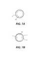
- FIGS. 7A and 7Billustrate exemplary cross-sectional shapes of a secondary balloon associated with the system of FIG. 6 .
- Examples of the present disclosurerelate to medical systems, devices, and methods for treating internal areas of a patient's body by establishing reverse blood flow in the ophthalmic artery.
- proximal and distalare used herein to refer to the relative positions of the components of an exemplary medical device or insertion device.
- proximalrefers to a position relatively closer to the exterior of the body or closer to a medical professional using the medical device or insertion device.
- distalrefers to a position relatively further away from the medical professional using the medical device or insertion device, or closer to the interior of the body.
- downstream and upstream or downstreamwhen used herein in relation to the subject's vasculature, refer respectively, to the direction of blood flow and the direction opposite that of blood flow, respectively.
- downstream or antegraderefers to the direction further from the heart
- upstream or “retrograde”refers to the direction closer to the heart.
- Reverse flowis the flow of blood opposite to the direction of blood flow under normal blood flow conditions.
- Reverse flowand “retrograde flow” are used synonymously. Reverse flow may be achieved by creating a pressure gradient so blood flow is reversed and directed, for example, from the treatment site into a lumen of a medical device to be rerouted to another location.
- FIG. 1illustrates various vasculature structures a subject.
- bloodmay flow from the heart through the internal carotid artery (ICA) 2 to the ophthalmic artery (OA) 4 to an eye 6 of the subject.
- the external carotid artery (ECA) 8may supply a flow of blood to the face and neck of a subject.
- Each of the ICA 2 and ECA 8branches off of the common carotid artery (CCA) 10 of the subject.
- the ECA 8branches into the facial artery (FA) 12 , the internal maxillary artery (IMA) 14 , and the supra trochlear artery (STA) 16 .
- FAfacial artery
- IMAinternal maxillary artery
- STAsupra trochlear artery
- IMA 14then branches into the sphenopalatine artery (SPA) 18 , and the middle meningeal artery (MMA) 24 .
- OA 4includes a number of branches such as the lacrimal artery (LA) 20 and the ethmoidal artery (EA) 22 .
- LAlacrimal artery
- EAethmoidal artery
- ICA 2 and ECA 8have several anastomoses (e.g., connections or junctures) which permit the exchange of blood therebetween.
- the anastomoses that relate to OA 4include: (1) anastomosis between SPA 18 and EA 22 ; (2) anastomosis between MMA 24 and LA 20 ; (3) anastomosis between STA 16 and LA 20 ; and (4) anastomosis between FA 12 and OA 4 .
- FIG. 2Aillustrates an exemplary system 28 for establishing reverse flow in OA 4 .
- a systemmay include a sheath 30 and an inflatable balloon 32 .
- Balloon 32may be mounted on or positioned about an external surface of sheath 30 .
- balloon 32may be formed as a cuff encircling a portion (e.g., a distal end portion) of sheath 30 .
- Balloon 32may be a compliant balloon and constructed of any appropriate materials (e.g., urethane polymer or thermoplastic rubber elastomer). Balloon 32 may have any appropriate shape and size. For example, upon expansion of balloon 32 , a cross-sectional dimension (e.g., diameter) of balloon 32 may be sized so as to contact a wall of ICA 2 . That is, a cross-sectional dimension (e.g., diameter) of balloon 32 in an expanded state may average about 4.62 mm.
- any appropriate materialse.g., urethane polymer or thermoplastic rubber elastomer. Balloon 32 may have any appropriate shape and size. For example, upon expansion of balloon 32 , a cross-sectional dimension (e.g., diameter) of balloon 32 may be sized so as to contact a wall of ICA 2 . That is, a cross-sectional dimension (e.g., diameter) of balloon 32 in an expanded state may average about 4.62 mm.
- Sheath 30may include a plurality of lumens.
- a first lumen 36may be a balloon inflation lumen. That is, first lumen 36 may have a first end fluidly coupled with a source of inflation fluid 38 (e.g., a gas such as air, or a liquid such as water or saline). A second end of first lumen 36 may extend through balloon 32 .
- first lumen 36may be fluidly coupled to an interior of balloon 32 via a side port/valve (not shown) such that upon delivery of fluid from source 38 to balloon 32 , balloon 32 may expand from a first, uninflated configuration (not shown) to an expanded configuration as shown in FIG. 2A .
- first lumen 36may be coupled to a source (not shown) of negative pressure (e.g., vacuum) such that upon actuation of the negative pressure source, balloon 32 may be deflated.
- a source of negative pressuree.g., vacuum
- a second lumen 40may extend through sheath 30 and between a proximal end and a distal end of sheath 30 , e.g., distal to balloon 32 .
- Second lumen 40may be a guide lumen such that sheath 30 and balloon 32 may be delivered over a guidewire or the like via second lumen 40 .
- second lumen 40may be configured for “rapid exchange” (RE) delivery.
- RErapid exchange
- second lumen 40may include a generally circular cross-sectional shape
- first lumen 36may include a generally semi-circular, crescent, or c-shaped cross-sectional shape along the entirety of its length. That is, as shown in FIG.
- second lumen 40may be nested or otherwise received within an opening or space defined by first lumen 36 . As such, a combined cross-sectional space or area occupied by first lumen 36 and second lumen 40 may be reduced. In such a manner, inflation fluid from source 38 may be passed through a c-shaped passage 37 within first lumen 36 , while a guidewire or the like may be passed through a passage 41 of second lumen 40 . Alternatively, second lumen 40 may be omitted and the system 28 may be arranged for “over-the-wire” (OTW) delivery. To that end, first lumen 36 may be dual-walled such that first lumen 36 includes an outer lumen wall 36 A and an inner lumen wall 36 B, as shown in FIG. 2C .
- inner lumen wall 36 Bmay extend through balloon 32 such that system 28 may be advanced over a guidewire (not shown) via a lumen formed radially within inner lumen wall 36 B. Additionally, outer lumen wall 36 A may terminate at a proximal end of balloon 32 . In such a manner, a space between outer lumen wall 36 A and inner lumen wall 36 B may be configured to deliver inflation fluid from source 28 to balloon 32 .
- a third lumen 42may extend from a proximal end to an opening 44 .
- Opening 44may extend through a sidewall of balloon 32 . That is, opening 44 enables communication between an environment (e.g., vasculature) within which balloon 32 is positioned and a proximal end of third lumen 42 (or sheath 30 ).
- an environmente.g., vasculature
- a proximal end of third lumen 42or sheath 30 .
- at least a portion (e.g., a distal portion) of balloon 32may be positioned distal to opening 44 while at least another portion (e.g., a proximal portion) of balloon 32 may be positioned proximal to opening 44 .
- a medical professionalmay access ICA 2 via any appropriate manner (e.g., an arterial cut down, etc.). Additionally, the medical professional may position a guidewire within the vasculature of a subject, extending an end of the guidewire into ICA 2 to a position distal of a junction between CCA 10 and ECA 8 , and optionally, distal to a junction between ICA 2 and OA 4 . Once so positioned, sheath 30 may be advanced over the guidewire into position within ICA 2 . For example, second lumen 40 of sheath 30 may be advanced over the guidewire until opening 44 of balloon 32 is aligned or otherwise across from OA 4 .
- sheath 30may be advanced such that the distal portion of balloon 32 is positioned distal to OA 4 while a proximal portion of balloon 32 is positioned proximal of OA 4 .
- Radiopaque or other markersmay be placed just distal and just proximal to opening 44 , and with suitable imaging or other viewing techniques, may assist in longitudinal and rotational positioning of sheath 32 and balloon 32 .
- the guidewiremay be removed from second lumen 40 of sheath 30 . Alternatively, the guidewire may remain within second lumen 40 during a remainder of the procedure.
- balloon 32may be expanded. That is, source 38 , coupled to first lumen 36 , may be actuated so as to inflate balloon 32 . Upon expansion of balloon 32 , balloon 32 may contact a wall of ICA 2 . Upon expansion, antegrade blood flow through ICA 2 may be prevented or blocked. However, as balloon 32 is positioned distal of the junction between CCA 10 and ECA 8 , antegrade blood flow between CCA 10 and ECA 8 is maintained. Such a continuation of antegrade flow between CCA 10 and ECA 8 serves to supply the two most common OA 4 to ECA 8 anastomoses including anastomosis between SPA 18 and EA 22 , and anastomosis between MMA 24 and LA 20 ( FIG. 1 ).
- the antegrade flow of blood from CCA 10 and ECA 8is maintained in order to ensure that an adequate supply of blood is available via the common anastomoses such that continuous retrograde movement of blood is ensured from OA 4 to ICA 2 .
- These common anastomosesinclude the orbital branch of the middle meningeal artery (MMA) 24 , the frontal branch of the supratrochlear artery (STA) 16 , the angular branch of the facial artery (FA) 12 , and the sphenopalatine branch of the internal maxillary artery (IMA) 14 .
- any plaque, emboli, or other material dislodged and/or fragmentedmay be prevented from flowing from ICA 2 toward the eye 6 via OA 4 , thereby preventing an embolic event (e.g., blindness, stroke, etc.).
- an additional balloon(not shown) may be inserted and inflated within the ECA 8 at a location distal of the junction between the ECA 8 and IMA 14 .
- the retrograde flow of blood from OA 4 to ICA 2may be passed through opening 44 and into third lumen 42 of sheath 30 .
- a proximal end of third lumen 42may be coupled to a filter and a return line (not shown) to return the filtered retrograde blood flow into a venous return site (e.g., into the internal jugular vein (IJV) of the subject) via any appropriate manner.
- a venous return sitee.g., into the internal jugular vein (IJV) of the subject
- an additional devicemay be advanced through third lumen 42 and into OA 4 .
- a guidewiremay be advanced through third lumen 42 into OA 4 such that one or more additional devices (e.g., balloons, stents, etc.) may be advanced into OA 4 for one or more additional procedures.
- additional devicese.g., balloons, stents, etc.
- FIG. 3illustrates a further exemplary system 50 for establishing reverse flow in OA 4 .
- the system 50 of FIG. 3includes features similar to those of the system 28 of FIG. 2A , and like components are illustrated with the same numbers.
- the system 50 of FIG. 3includes sheath 30 , a balloon 32 , a first lumen 36 coupled to a source of inflation fluid 38 , a second lumen 40 , and a third lumen 42 terminating in an opening 44 .
- the system 50 of FIG. 3includes a fourth lumen 52 .
- fourth lumen 52extends through the length of balloon 32 so as to enable fluid communication between a region of ICA 2 proximal or upstream of balloon 32 and a region of ICA 2 distal or downstream of balloon 32 , via openings 53 and 55 of fourth lumen 52 .
- fourth lumen 52may enable retrograde ICA 2 blood flow to pass therethrough.
- fourth lumen 52may comprise a perfusion lumen, thereby enabling antegrade blood flow through ICA 2 .
- only the ICA 2is blocked with a balloon.
- the ECA 8 and the CCA 10will not have balloons placed in their respective lumens.
- the ICA 2When the ICA 2 is blocked to induce reverse flow, blood will flow out of the related segment of the ICA 2 and the OA 4 creating a lower blood pressure in the OA 4 and related anastomoses. This lower pressure will facilitate blood flow from a higher-pressure area (e.g., ECA 8 ).
- the overall blood flow circuitis enabled by allowing normal antegrade blood to flow up the CCA 10 and into the ECA 8 . From the ECA 8 , the previously described anastomoses provide a pathway for the blood to enter into the ICA 2 . Blood will flow from the higher pressure ECA 8 , through the anastomoses, into the OA 4 and out into the ICA 2 (e.g., in a retrograde fashion).
- fourth lumen 52is shown as a through lumen extending through balloon 32 , in some arrangements, fourth lumen 52 (or a pair or plurality of fourth lumens 52 ) may be arranged as a channel(s) (e.g., a groove, indent or the like) extending along an outermost surface balloon 32 .
- a channel(s)e.g., a groove, indent or the like
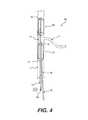
- FIG. 4illustrates a further exemplary system 60 for establishing reverse flow in OA 4 .
- the system 60 of FIG. 4includes features similar to those of the systems 28 and 50 of FIGS. 2A and 3 , respectively, and like components are illustrated with the same reference numbers.
- system 60includes a pair of balloons.
- system 60includes a first balloon 62 and a second balloon 64 coupled to a sheath 66 .
- a first lumen 68e.g., a balloon inflation lumen, may extend through sheath 66 .
- First lumen 68may have a first end fluidly coupled with a source of inflation fluid 70 (e.g., a gas such as air, or a liquid such as water or saline).
- a source of inflation fluid 70e.g., a gas such as air, or a liquid such as water or saline.
- a second end of first lumen 68may extend through first balloon 62 and second balloon 64 , and, via any appropriate arrangement of valve(s) or the like (not shown), be fluidly coupled to an interior of one or both of first balloon 62 and second balloon 64 .
- balloon(s) 62 , 64may expand from a first, uninflated configuration (not shown) to a second, expanded configuration as shown in FIG. 4 .
- first lumen 68may simultaneously expand both the first balloon 62 and the second balloon 64 .
- first lumen 68may comprise a pair of lumens such that one of the pair of first lumens 68 may terminate within the interior of first balloon 62 while another of the pair of first lumens 68 terminates within the interior of second balloon 64 .
- each of first balloon 62 and second balloon 64may be individually expanded (e.g., inflated) and/or deflated.
- sheath 66may include a second lumen 72 , extending from a proximal end of sheath 66 to a distalmost end of sheath 66 .
- Second lumen 72may be a guide lumen such that sheath 66 , first balloon 62 , and second balloon 64 may be delivered over a guidewire or the like via second lumen 72 .
- Second lumen 72may be arranged as an “over-the-wire” (OTW) lumen or configured for “rapid exchange” (RE) delivery.
- OGWover-the-wire
- RErapid exchange
- a third lumen 74may extend from a proximal end to an opening 76 extending through a distal end portion of first balloon 62 .
- Opening 76enables communication between an environment (e.g., vasculature) within which first balloon 62 is positioned and a proximal end of third lumen 74 (or sheath 66 ).
- third lumen 74terminates at opening 76 of first balloon 62 , and does not extend through second balloon 64 .
- a fourth lumen 78extends along sheath 66 and through the length of first balloon 62 and second balloon 64 , between proximal opening 77 and distal opening 79 , so as to enable fluid communication between a region of ICA 2 proximal or upstream of first balloon 62 and a region of ICA 2 distal or downstream of second balloon 64 .
- fourth lumen 78may enable retrograde blood flow to pass therethrough.
- fourth lumen 78may comprise a perfusion lumen, thereby enabling antegrade blood flow through ICA 2 .
- fourth lumen 78is shown as a through lumen extending through first balloon 62 and second balloon 64 , in some arrangements, fourth lumen 78 (or a pair or plurality of fourth lumens 78 ) may be arranged as a channel(s) (e.g., a groove, indent or the like) extending along an outermost surface first balloon 62 and second balloon 64 , similar to that discussed in connection with FIG. 3 .
- a channel(s)e.g., a groove, indent or the like
- the medical professionalmay position a guidewire within the vasculature of a subject, extending an end of the guidewire into ICA 2 to a position distal of a junction between CCA 10 and ECA 8 , and optionally, distal to a junction between ICA 2 and OA 4 .
- sheath 66may be advanced over the guidewire into position within ICA 2 such that second balloon 64 is positioned distal to OA 4 while a first balloon 62 is positioned proximal of OA 4 .
- the guidewiremay be removed from second lumen 72 of sheath 66 .
- the guidewiremay be left in second lumen 72 throughout the procedure.
- first balloon 62 and second balloon 64may be expanded. That is, source 70 , coupled to first lumen 68 (or pair of first lumens 68 ), may be actuated so as to inflate first balloon 62 and second balloon 64 (e.g., either simultaneously or individually). First balloon 62 may be expanded so as to contact a wall of ICA 2 upstream or proximal of OA 4 , while second balloon 64 may be expanded so as to contact a wall of ICA 2 downstream or distal of OA 4 . As first balloon 62 and second balloon 64 are both positioned distal of the junction between CCA 10 and ECA 8 , antegrade blood flow between CCA 10 and ECA 8 is maintained.
- first balloon 62 and second balloon 64induces a pressure differential in the vasculature such that retrograde blood flow is induced from OA 4 towards ICA 2 .
- the induced retrograde blood flowmay be passed through first balloon 62 and through sheath 66 via third lumen 74 .
- any plaque, emboli, or other material dislodged and/or fragmentedmay be prevented from flowing from ICA 2 toward the eye 6 via OA 4 , thereby preventing an embolic event (e.g., blindness, stroke, etc.).
- a proximal end of third lumen 74may be coupled to a filter and a return line (not shown) to return the filtered retrograde blood flow into a venous return site (e.g., into the internal jugular vein (IJV) of the subject) via any appropriate manner.
- an additional devicee.g., one or more of a guidewire, a balloon, a stent, etc.
- fourth lumen 78or a pair of fourth lumens 78 , may enable antegrade ICA 2 and/or retrograde ICA 2 blood flow therethrough.
- fourth lumen 78may extend through only first balloon 62 . That is, in contrast to the arrangement shown in FIG. 4 in which fourth lumen 78 extends through sheath 66 , through first balloon 62 , and through second balloon 64 , fourth lumen 78 shown in FIG. 5 extends only through sheath 66 and through first balloon 62 and terminate in a distal opening 79 . In such a manner, fourth lumen 78 may be used to convey retrograde blood flow from OA 4 . That is, the retrograde flow of blood from OA 4 to ICA 2 may be passed through into fourth lumen 78 via distal opening 79 .
- a proximal end of fourth lumen 78may be coupled to a filter and a return line (not shown) to return the filtered retrograde blood flow into a venous return site (e.g., into the internal jugular vein (IJV) of the subject) via any appropriate manner.
- a venous return sitee.g., into the internal jugular vein (IJV) of the subject
- third lumen 74may be reserved for advancement and retraction of additional devices (e.g., one or more of a guidewire, a balloon, a stent, etc.) therethrough, out of a distal opening 75 , and into OA 4 for one or more additional procedures, if deemed necessary or desirable by a medical professional.
- FIG. 6illustrates a further exemplary system 90 for establishing reverse flow in OA 4 .
- the system 90may include a sheath 92 and a first (e.g., proximal) balloon 94 .
- Sheath 90e.g., a catheter
- a first lumen 96may be a balloon inflation lumen. That is, first lumen 96 may have a first end fluidly coupled with a source of inflation fluid 98 (e.g., a gas such as air, or a liquid such as water or saline).
- a second end of first lumen 96may extend through a distalmost end of first balloon 94 .
- first lumen 96may be fluidly coupled to an interior of a first balloon 94 via a side port/valve (not shown). Upon delivery of fluid from source 98 to first balloon 94 via first lumen 96 , first balloon 94 may expand from a first, uninflated configuration (not shown) to an expanded configuration as shown in FIG. 6 . Additionally, first lumen 96 may be coupled to a source of negative pressure (e.g., vacuum) such that upon actuation of the negative pressure source, balloon 32 may be deflated. First lumen 96 also may facilitate delivery of sheath 92 and first balloon 94 to a desired location within the vasculature of a subject.
- a source of negative pressuree.g., vacuum
- first lumen 96may be arranged as an “over-the-wire” (OTW) lumen in which a guidewire may be thread through first lumen 96 , from a proximal end to a distal end of first lumen 96 .
- first lumen 96may be configured for “rapid exchange” (RE) delivery, in other arrangements, a separate guidewire lumen may be used.
- RErapid exchange
- a second lumen 100may extend from a proximal end of sheath 92 to an opening 102 .
- an additional devicemay be advanced through second lumen 100 and into OA 4 .
- a guidewiremay be advanced through second lumen 100 , out through opening 102 , and into OA 4 such that one or more additional devices (e.g., balloons, stents, etc.) may be advanced into OA 4 for one or more additional procedures.
- a third lumen 104may extend from a proximal end of sheath 92 to an opening 106 , thereby enabling fluid communication between a region of ICA 2 distal of first balloon 94 and a region of ICA 2 proximal of first balloon 94 .
- retrograde blood flow of ICA 2 and/or OA 4may be passed through opening 106 , through third lumen 104 , and permitted to pass through a filter (not shown) and venous return line (not shown) so as to introduce the retrograde blood flow into a venous site (e.g., the IJV) via any appropriate manner.
- a filternot shown
- venous return linenot shown
- Shaft 110 and second balloon 108may be delivered distally of first balloon 94 via first lumen 96 .
- a relative positioning between first balloon 94 and second balloon 108may be adjusted by manipulation (e.g., movement) of one or both of shaft 110 and sheath 92 .
- Second balloon 108may be a compliant balloon and constructed of any appropriate materials (e.g., urethane polymer or thermoplastic rubber elastomer). Second balloon 108 may have any appropriate shape and size. For example, upon expansion of second balloon 108 , a cross-sectional dimension (e.g., diameter) of second balloon 108 may be sized so as to restrict blood flow past second balloon 108 .
- second balloon 108may induce a venturi effect so as to increase a blood flow rate, and thereby, induce retrograde blood flow in OA 4 , as will be described in further detail.
- second balloon 108is not configured to form a complete seal against the wall of ICA 2 .
- balloon 108may have a cross-sectional shape or size configured to be spaced from a wall of ICA 2 . That is, as shown in FIG.
- balloon 108may have a generally circular cross-sectional shape where a diameter of the balloon 108 is smaller than a diameter of ICA 2 so that blood flow may continue to pass between an exterior surface of balloon 108 and an interior wall or surface of ICA 2 .
- an exterior surface of balloon 108may include one or more grooves, recesses, or channels 112 to promote blood flow within ICA 2 .
- second balloon 108may be adjustable so as to provide dynamic control of blood flow around or past second balloon 108 . That is, following expansion of second balloon 108 to a first size and/or shape, an amount of inflation fluid from a source of inflation fluid (e.g., a gas such as air, or a liquid such as water or saline) to second balloon 108 may be adjusted so as to increase and/or decrease, as desired, a size or shape of second balloon 108 .
- a source of inflation fluide.g., a gas such as air, or a liquid such as water or saline
- the medical professionalmay position a guidewire within the vasculature of a subject and sheath 92 may be advanced over the guidewire (via first lumen 96 ) into position within ICA 2 , as shown in FIG. 6 . That is, sheath 92 may be advanced until first balloon 94 extends into ICA 2 , just past the junction between CCA 10 and ICA 2 , and distal to the junction between CCA 10 and ECA 8 . In such a manner, antegrade blood flow between CCA 10 and ECA 8 is maintained. Once in position, the guidewire may be removed from first lumen 96 of sheath 92 .
- first balloon 94may be expanded. That is, source 98 , coupled to first lumen 96 , may be actuated so as to inflate first balloon 94 and to block antegrade blood flow in ICA 2 .
- First balloon 94may be expanded so as to contact a wall of ICA 2 upstream of OA 4 and downstream of the junction between CCA 10 and ICA 2 .
- shaft 110may be extended through first lumen 96 so as to advance second balloon 108 to a desired location within ICA 2 . As shown in FIG. 6 , for example, second balloon 108 may be advanced to a location distal to OA 4 .
- a source of inflation fluidmay be delivered to second balloon 108 (e.g., via shaft 110 ) to inflate or otherwise expand second balloon 108 , thereby increasing a blood flow rate of blood in the ICA 2 , and inducing retrograde blood flow in OA 4 while maintaining antegrade blood flow in ECA 8 . That is, inflation or expansion of one or both of first balloon 94 and second balloon 108 induces a pressure differential in the vasculature such that retrograde blood flow is induced from OA 4 towards ICA 2 .
- the induced retrograde blood flowmay be passed through first balloon 94 and through sheath 92 via third lumen 104 .
- any plaque, emboli, or other material dislodged and/or fragmentedmay be prevented from flowing from ICA 2 toward the eye 6 via OA 4 , thereby preventing an embolic event (e.g., blindness, stroke, etc.).
- an embolic evente.g., blindness, stroke, etc.
- a proximal end of third lumen 104may be coupled to a filter and a return line (not shown) to return the filtered retrograde blood flow into a venous return site (e.g., into the internal jugular vein (IJV) of the subject) via any appropriate manner.
- a venous return sitee.g., into the internal jugular vein (IJV) of the subject
- an additional devicee.g., one or more of a guidewire, a balloon, a stent, etc.
- shaft 110 and second balloon 108may be omitted.
- first balloon 94may be used alone so as to impede antegrade blood flow in ICA 2 .
Landscapes
- Health & Medical Sciences (AREA)
- Life Sciences & Earth Sciences (AREA)
- Surgery (AREA)
- Heart & Thoracic Surgery (AREA)
- Animal Behavior & Ethology (AREA)
- Veterinary Medicine (AREA)
- Public Health (AREA)
- Engineering & Computer Science (AREA)
- Biomedical Technology (AREA)
- General Health & Medical Sciences (AREA)
- Vascular Medicine (AREA)
- Molecular Biology (AREA)
- Medical Informatics (AREA)
- Nuclear Medicine, Radiotherapy & Molecular Imaging (AREA)
- Reproductive Health (AREA)
- Child & Adolescent Psychology (AREA)
- Biophysics (AREA)
- Pulmonology (AREA)
- Anesthesiology (AREA)
- Hematology (AREA)
- Media Introduction/Drainage Providing Device (AREA)
- Surgical Instruments (AREA)
Abstract
Description
Claims (17)
Priority Applications (2)
| Application Number | Priority Date | Filing Date | Title |
|---|---|---|---|
| US16/178,163US10398880B2 (en) | 2017-11-02 | 2018-11-01 | Medical systems, devices, and related methods |
| US16/447,414US11213659B2 (en) | 2017-11-02 | 2019-06-20 | Medical systems, devices, and related methods |
Applications Claiming Priority (2)
| Application Number | Priority Date | Filing Date | Title |
|---|---|---|---|
| US201762580665P | 2017-11-02 | 2017-11-02 | |
| US16/178,163US10398880B2 (en) | 2017-11-02 | 2018-11-01 | Medical systems, devices, and related methods |
Related Child Applications (1)
| Application Number | Title | Priority Date | Filing Date |
|---|---|---|---|
| US16/447,414ContinuationUS11213659B2 (en) | 2017-11-02 | 2019-06-20 | Medical systems, devices, and related methods |
Publications (2)
| Publication Number | Publication Date |
|---|---|
| US20190126013A1 US20190126013A1 (en) | 2019-05-02 |
| US10398880B2true US10398880B2 (en) | 2019-09-03 |
Family
ID=66245374
Family Applications (2)
| Application Number | Title | Priority Date | Filing Date |
|---|---|---|---|
| US16/178,163ActiveUS10398880B2 (en) | 2017-11-02 | 2018-11-01 | Medical systems, devices, and related methods |
| US16/447,414Active2039-07-29US11213659B2 (en) | 2017-11-02 | 2019-06-20 | Medical systems, devices, and related methods |
Family Applications After (1)
| Application Number | Title | Priority Date | Filing Date |
|---|---|---|---|
| US16/447,414Active2039-07-29US11213659B2 (en) | 2017-11-02 | 2019-06-20 | Medical systems, devices, and related methods |
Country Status (1)
| Country | Link |
|---|---|
| US (2) | US10398880B2 (en) |
Cited By (1)
| Publication number | Priority date | Publication date | Assignee | Title |
|---|---|---|---|---|
| US11213659B2 (en)* | 2017-11-02 | 2022-01-04 | J.D. Franco & Co., Llc | Medical systems, devices, and related methods |
Families Citing this family (1)
| Publication number | Priority date | Publication date | Assignee | Title |
|---|---|---|---|---|
| WO2024192503A1 (en)* | 2023-03-17 | 2024-09-26 | Mg Stroke Analytics Inc. | Catheter system having sealing system for preventing back-flow within cerebral vessels |
Citations (84)
| Publication number | Priority date | Publication date | Assignee | Title |
|---|---|---|---|---|
| US2690595A (en) | 1951-06-22 | 1954-10-05 | Davol Rubber Co | Manufacture of low-pressure inflation catheters |
| US3367101A (en) | 1959-05-22 | 1968-02-06 | Spunize Co Of America Inc | Crimped roving or sliver |
| US3435826A (en) | 1964-05-27 | 1969-04-01 | Edwards Lab Inc | Embolectomy catheter |
| US4224929A (en)* | 1977-11-08 | 1980-09-30 | Olympus Optical Co., Ltd. | Endoscope with expansible cuff member and operation section |
| US4403612A (en) | 1980-10-20 | 1983-09-13 | Fogarty Thomas J | Dilatation method |
| US4926858A (en) | 1984-05-30 | 1990-05-22 | Devices For Vascular Intervention, Inc. | Atherectomy device for severe occlusions |
| US5000734A (en)* | 1988-02-01 | 1991-03-19 | Georges Boussignac | Probe intended to be introduced within a living body |
| US5026384A (en) | 1989-11-07 | 1991-06-25 | Interventional Technologies, Inc. | Atherectomy systems and methods |
| US5176693A (en) | 1992-05-11 | 1993-01-05 | Interventional Technologies, Inc. | Balloon expandable atherectomy cutter |
| US5395311A (en) | 1990-05-14 | 1995-03-07 | Andrews; Winston A. | Atherectomy catheter |
| US5554119A (en)* | 1991-08-02 | 1996-09-10 | Scimed | Drug delivery catheter with manifold |
| US5709701A (en) | 1996-05-30 | 1998-01-20 | Parodi; Juan C. | Apparatus for implanting a prothesis within a body passageway |
| US5820595A (en) | 1995-06-07 | 1998-10-13 | Parodi; Juan C. | Adjustable inflatable catheter and method for adjusting the relative position of multiple inflatable portions of a catheter within a body passageway |
| WO1998052639A1 (en) | 1997-05-19 | 1998-11-26 | United States Surgical Corporation | Catheter system |
| WO1998053761A1 (en) | 1997-05-26 | 1998-12-03 | William A. Cook Australia Pty. Ltd. | A prosthesis and a method and means of deploying a prosthesis |
| US5897567A (en) | 1993-04-29 | 1999-04-27 | Scimed Life Systems, Inc. | Expandable intravascular occlusion material removal devices and methods of use |
| US5951514A (en)* | 1997-03-07 | 1999-09-14 | Sahota; Harvinder | Multi-lobe perfusion balloon |
| WO2000054673A1 (en) | 1999-03-16 | 2000-09-21 | Percusurge, Inc. | Apparatus for containing and removing occlusions in the carotid arteries |
| US6146370A (en) | 1999-04-07 | 2000-11-14 | Coaxia, Inc. | Devices and methods for preventing distal embolization from the internal carotid artery using flow reversal by partial occlusion of the external carotid artery |
| US6206868B1 (en) | 1998-03-13 | 2001-03-27 | Arteria Medical Science, Inc. | Protective device and method against embolization during treatment of carotid artery disease |
| US20010001114A1 (en) | 1996-05-14 | 2001-05-10 | Embol-X, Inc. | Cardioplegia balloon cannula |
| US6302908B1 (en) | 1997-03-24 | 2001-10-16 | Juan Carlos Parodi | Arterial graft device and method of positioning the same |
| US6336933B1 (en) | 1998-03-13 | 2002-01-08 | Juan C. Parodi | Endovascular device for application of prosthesis with sutures |
| US6344054B1 (en) | 1996-09-20 | 2002-02-05 | Juan Carlos Parodi | Endoluminal prosthesis comprising stent and overlying graft cover, and system and method for deployment thereof |
| US6413235B1 (en) | 1998-03-13 | 2002-07-02 | Arteria Medical Science, Inc. | Protective device against embolization in carotid angioplasty |
| US20020087128A1 (en) | 2000-08-31 | 2002-07-04 | Mpnb Ltd. | Microsurgical injection and/or distending instruments and surgical method and apparatus utilizing same |
| US6423032B2 (en) | 1998-03-13 | 2002-07-23 | Arteria Medical Science, Inc. | Apparatus and methods for reducing embolization during treatment of carotid artery disease |
| US20020151922A1 (en) | 1998-05-13 | 2002-10-17 | Michael Hogendijk | Apparatus and methods for removing emboli during a surgical procedure |
| US20020165573A1 (en)* | 2001-05-01 | 2002-11-07 | Coaxia, Inc. | Devices and methods for preventing distal embolization using flow reversal and perfusion augmentation within the cerebral vasculature |
| US20030023200A1 (en) | 1999-03-01 | 2003-01-30 | Coaxia, Inc. | Partial aortic occlusion devices and methods for cerebral perfusion augmentation |
| WO2003018085A2 (en) | 2001-08-22 | 2003-03-06 | Arteria Medical Science, Inc. | Apparatus and methods for treating stroke and controlling cerebral flow characteristics |
| US6540712B1 (en) | 1998-03-13 | 2003-04-01 | Arteria Medical Science, Inc. | Methods and low profile apparatus for reducing embolization during treatment of carotid artery disease |
| US20030199819A1 (en) | 2002-04-17 | 2003-10-23 | Beck Robert C. | Filter wire system |
| US20030199802A1 (en) | 1999-01-15 | 2003-10-23 | Denise Barbut | Methods for flow augmentation in patients with occlusive cerebrovascular disease |
| US20030203958A1 (en) | 1997-03-31 | 2003-10-30 | Neorx Corporation | Therapeutic inhibitor of vascular smooth muscle cells |
| US6641573B1 (en) | 1999-03-25 | 2003-11-04 | Arteria Medical Science, Inc. | Device and method of guide wire balloon inflation and deflation to prevent cerebral embolization during carotid stenting |
| US6645222B1 (en) | 1998-05-13 | 2003-11-11 | Arteria Medical Science, Inc. | Puncture resistant branch artery occlusion device and methods of use |
| US6824558B2 (en) | 1998-08-25 | 2004-11-30 | Boston Scientific Corporation | Endoluminal device and method for treating branched lumen having a restricted section |
| US6827726B2 (en) | 2001-01-19 | 2004-12-07 | Boston Scientific Corporation | Introducer for deployment of branched prosthesis |
| US6837881B1 (en) | 2001-02-23 | 2005-01-04 | Coaxia, Inc. | Devices and methods for preventing distal embolization using flow reversal by partial occlusion of the brachiocephalic artery |
| US6902540B2 (en) | 2001-08-22 | 2005-06-07 | Gerald Dorros | Apparatus and methods for treating stroke and controlling cerebral flow characteristics |
| US6908474B2 (en) | 1998-05-13 | 2005-06-21 | Gore Enterprise Holdings, Inc. | Apparatus and methods for reducing embolization during treatment of carotid artery disease |
| US20050149117A1 (en) | 2003-12-24 | 2005-07-07 | Farhad Khosravi | Apparatus and methods for delivering sealing materials during a percutaneous procedure to facilitate hemostasis |
| US6929634B2 (en) | 2001-08-22 | 2005-08-16 | Gore Enterprise Holdings, Inc. | Apparatus and methods for treating stroke and controlling cerebral flow characteristics |
| US6936053B1 (en) | 1998-07-02 | 2005-08-30 | Jeffrey N. Weiss | Ocular implant needle |
| US20060136022A1 (en) | 2004-11-23 | 2006-06-22 | Wong Edward K Jr | Medical device and method for temperature control and treatment of the eye and surrounding tissues |
| US20060259132A1 (en) | 2005-05-02 | 2006-11-16 | Cook Incorporated | Vascular stent for embolic protection |
| US7214201B2 (en) | 1991-06-18 | 2007-05-08 | Boston Scientific Scimed, Inc. | Intravascular guide wire and method for manufacture thereof |
| US7235095B2 (en) | 2002-02-22 | 2007-06-26 | Scimed Life Systems, Inc. | Method and system for deploying multi-part endoluminal devices |
| WO2007103464A2 (en) | 2006-03-08 | 2007-09-13 | Orqis Medical Corporation | Blood conduit connector |
| US7309334B2 (en) | 2002-07-23 | 2007-12-18 | Von Hoffmann Gerard | Intracranial aspiration catheter |
| US20080027519A1 (en) | 2006-07-28 | 2008-01-31 | Guerrero John M | Method of treatment of ocular compartment syndromes |
| US7384411B1 (en)* | 1997-02-19 | 2008-06-10 | Condado Medical Devices Corporation | Multi-purpose catheters, catheter systems, and radiation treatment |
| US20080243229A1 (en) | 1996-09-18 | 2008-10-02 | Micro Therapeutics, Inc. | Intracranial Stent and Method of Use |
| US20090018455A1 (en) | 2003-11-21 | 2009-01-15 | Silk Road Medical, Inc. | Method and apparatus for treating a carotid artery |
| US20090024072A1 (en) | 2007-07-18 | 2009-01-22 | Enrique Criado | Methods and systems for establishing retrograde carotid arterial blood flow |
| US20090030323A1 (en) | 2007-04-02 | 2009-01-29 | Doheny Eye Institute | Ultrasound and Microbubbles in Ocular Diagnostics and Therapies |
| US7604612B2 (en) | 2001-05-01 | 2009-10-20 | St. Jude Medical, Cardiology Division, Inc. | Emboli protection devices and related methods of use |
| US20100076365A1 (en)* | 2008-08-21 | 2010-03-25 | Howard Riina | Method and apparatus for accessing the wall of a vascular structure or other body lumen while simultaneously providing zone isolation and fluid bypass capability |
| US20100125244A1 (en) | 2008-11-14 | 2010-05-20 | Medtronic Vascular, Inc. | Balloon catheter for crossing a chronic total occlusion |
| US7867273B2 (en) | 2007-06-27 | 2011-01-11 | Abbott Laboratories | Endoprostheses for peripheral arteries and other body vessels |
| US20110143993A1 (en) | 2009-12-15 | 2011-06-16 | The Brigham And Women's Hospital, Inc. | Endothelial basement membrane targeting peptide ligands |
| US20110152683A1 (en) | 2011-03-01 | 2011-06-23 | Gerrans Lawrence J | Abrading Balloon Catheter for Extravasated Drug Delivery |
| US20120046679A1 (en) | 2010-07-01 | 2012-02-23 | Patel Himanshu N | Atherectomy catheters with longitudinally displaceable drive shafts |
| US20120101510A1 (en) | 2008-12-23 | 2012-04-26 | Reverse Medical Corporation | Systems And Methods For Removing Obstructive Matter From Body Lumens And Treating Vascular Defects |
| US8353850B2 (en) | 2005-07-07 | 2013-01-15 | St. Jude Medical, Cardiology Division, Inc. | Steerable guide wire with torsionally stable tip |
| US20130197621A1 (en) | 2010-08-12 | 2013-08-01 | Silk Road Medical, Inc. | Systems and methods for treating a carotid artery |
| US8545432B2 (en) | 2009-06-03 | 2013-10-01 | Silk Road Medical, Inc. | System and methods for controlling retrograde carotid arterial blood flow |
| US20130281788A1 (en) | 2011-08-05 | 2013-10-24 | Silk Road Medical, Inc. | Methods and systems for treatment of acute ischemic stroke |
| WO2014022866A1 (en) | 2012-08-03 | 2014-02-06 | J.D. Franco & Company | Devices and methods for treating occlusion of the ophthalmic artery |
| US20140154246A1 (en) | 2004-09-24 | 2014-06-05 | Rfe Pharma Llc | Cai-based systems and methods for the localized treatment of ocular and other diseases |
| US8834404B2 (en) | 2009-03-30 | 2014-09-16 | Steve Andre Beaudin | Apparatus, system and methods for extracorporeal blood processing for selectively cooling the brain relative to the body during hyperthermic treatment or to induce hypothermia of the brain |
| US8852226B2 (en) | 1997-11-07 | 2014-10-07 | Salviac Limited | Vascular device for use during an interventional procedure |
| US8863631B1 (en) | 2013-07-29 | 2014-10-21 | Insera Therapeutics, Inc. | Methods of manufacturing flow diverting devices |
| US20150272732A1 (en)* | 2012-10-18 | 2015-10-01 | Loma Vista Medical, Inc. | Reinforced inflatable medical devices |
| US20150313607A1 (en) | 2014-05-04 | 2015-11-05 | Zhadkevich Medical, Inc. | Noninvasive protection from emboli |
| US20150366580A1 (en) | 2014-06-19 | 2015-12-24 | Limflow Gmbh | Devices and methods for treating lower extremity vasculature |
| US9241699B1 (en) | 2014-09-04 | 2016-01-26 | Silk Road Medical, Inc. | Methods and devices for transcarotid access |
| US9259215B2 (en) | 2007-07-18 | 2016-02-16 | Silk Road Medical, Inc. | Systems and methods for treating a carotid artery |
| US9265512B2 (en) | 2013-12-23 | 2016-02-23 | Silk Road Medical, Inc. | Transcarotid neurovascular catheter |
| US20160166754A1 (en) | 2013-07-31 | 2016-06-16 | Hyo Won Choi | Unitary body systems and devices and methods to use the same for retroperfusion |
| WO2016109586A1 (en) | 2014-12-29 | 2016-07-07 | Ocudyne, Llc | Apparatus and method for treating eye diseases |
| US20170164963A1 (en)* | 2015-12-14 | 2017-06-15 | Mayank Goyal | Systems and methods to improve perfusion pressure during endovascular intervention |
| WO2017156333A1 (en) | 2016-03-09 | 2017-09-14 | J.D. Franco & Co. | Systems and methods for treating eye diseases using retrograde blood flow |
Family Cites Families (4)
| Publication number | Priority date | Publication date | Assignee | Title |
|---|---|---|---|---|
| US5904659A (en)* | 1997-02-14 | 1999-05-18 | Exogen, Inc. | Ultrasonic treatment for wounds |
| JP4880693B2 (en)* | 2006-10-02 | 2012-02-22 | パイオニア株式会社 | Image display device |
| US10428883B2 (en)* | 2015-07-17 | 2019-10-01 | Bendix Spicer Foundation Brake Llc | Drum brake assembly configured to reduce audible noise during braking |
| US10398880B2 (en)* | 2017-11-02 | 2019-09-03 | J.D. Franco & Co., Llc | Medical systems, devices, and related methods |
- 2018
- 2018-11-01USUS16/178,163patent/US10398880B2/enactiveActive
- 2019
- 2019-06-20USUS16/447,414patent/US11213659B2/enactiveActive
Patent Citations (95)
| Publication number | Priority date | Publication date | Assignee | Title |
|---|---|---|---|---|
| US2690595A (en) | 1951-06-22 | 1954-10-05 | Davol Rubber Co | Manufacture of low-pressure inflation catheters |
| US3367101A (en) | 1959-05-22 | 1968-02-06 | Spunize Co Of America Inc | Crimped roving or sliver |
| US3435826A (en) | 1964-05-27 | 1969-04-01 | Edwards Lab Inc | Embolectomy catheter |
| US4224929A (en)* | 1977-11-08 | 1980-09-30 | Olympus Optical Co., Ltd. | Endoscope with expansible cuff member and operation section |
| US4403612A (en) | 1980-10-20 | 1983-09-13 | Fogarty Thomas J | Dilatation method |
| US4926858A (en) | 1984-05-30 | 1990-05-22 | Devices For Vascular Intervention, Inc. | Atherectomy device for severe occlusions |
| US5000734A (en)* | 1988-02-01 | 1991-03-19 | Georges Boussignac | Probe intended to be introduced within a living body |
| US5026384A (en) | 1989-11-07 | 1991-06-25 | Interventional Technologies, Inc. | Atherectomy systems and methods |
| US5395311A (en) | 1990-05-14 | 1995-03-07 | Andrews; Winston A. | Atherectomy catheter |
| US7214201B2 (en) | 1991-06-18 | 2007-05-08 | Boston Scientific Scimed, Inc. | Intravascular guide wire and method for manufacture thereof |
| US5554119A (en)* | 1991-08-02 | 1996-09-10 | Scimed | Drug delivery catheter with manifold |
| US5176693A (en) | 1992-05-11 | 1993-01-05 | Interventional Technologies, Inc. | Balloon expandable atherectomy cutter |
| US5897567A (en) | 1993-04-29 | 1999-04-27 | Scimed Life Systems, Inc. | Expandable intravascular occlusion material removal devices and methods of use |
| US5820595A (en) | 1995-06-07 | 1998-10-13 | Parodi; Juan C. | Adjustable inflatable catheter and method for adjusting the relative position of multiple inflatable portions of a catheter within a body passageway |
| US20010001114A1 (en) | 1996-05-14 | 2001-05-10 | Embol-X, Inc. | Cardioplegia balloon cannula |
| US5709701A (en) | 1996-05-30 | 1998-01-20 | Parodi; Juan C. | Apparatus for implanting a prothesis within a body passageway |
| US7901445B2 (en) | 1996-09-18 | 2011-03-08 | Micro Therapeutics, Inc. | Intracranial stent and method of use |
| US20080243229A1 (en) | 1996-09-18 | 2008-10-02 | Micro Therapeutics, Inc. | Intracranial Stent and Method of Use |
| US6344054B1 (en) | 1996-09-20 | 2002-02-05 | Juan Carlos Parodi | Endoluminal prosthesis comprising stent and overlying graft cover, and system and method for deployment thereof |
| US7384411B1 (en)* | 1997-02-19 | 2008-06-10 | Condado Medical Devices Corporation | Multi-purpose catheters, catheter systems, and radiation treatment |
| US5951514A (en)* | 1997-03-07 | 1999-09-14 | Sahota; Harvinder | Multi-lobe perfusion balloon |
| US6302908B1 (en) | 1997-03-24 | 2001-10-16 | Juan Carlos Parodi | Arterial graft device and method of positioning the same |
| US6855162B2 (en) | 1997-03-24 | 2005-02-15 | Scimed Life Systems, Inc. | Arterial graft device |
| US20030203958A1 (en) | 1997-03-31 | 2003-10-30 | Neorx Corporation | Therapeutic inhibitor of vascular smooth muscle cells |
| WO1998052639A1 (en) | 1997-05-19 | 1998-11-26 | United States Surgical Corporation | Catheter system |
| WO1998053761A1 (en) | 1997-05-26 | 1998-12-03 | William A. Cook Australia Pty. Ltd. | A prosthesis and a method and means of deploying a prosthesis |
| US8852226B2 (en) | 1997-11-07 | 2014-10-07 | Salviac Limited | Vascular device for use during an interventional procedure |
| US6336933B1 (en) | 1998-03-13 | 2002-01-08 | Juan C. Parodi | Endovascular device for application of prosthesis with sutures |
| US6206868B1 (en) | 1998-03-13 | 2001-03-27 | Arteria Medical Science, Inc. | Protective device and method against embolization during treatment of carotid artery disease |
| US6413235B1 (en) | 1998-03-13 | 2002-07-02 | Arteria Medical Science, Inc. | Protective device against embolization in carotid angioplasty |
| US6423032B2 (en) | 1998-03-13 | 2002-07-23 | Arteria Medical Science, Inc. | Apparatus and methods for reducing embolization during treatment of carotid artery disease |
| US6905490B2 (en) | 1998-03-13 | 2005-06-14 | Gore Enterprise Holdings, Inc. | Apparatus and methods for reducing embolization during treatment of carotid artery disease |
| US6540712B1 (en) | 1998-03-13 | 2003-04-01 | Arteria Medical Science, Inc. | Methods and low profile apparatus for reducing embolization during treatment of carotid artery disease |
| US20020151922A1 (en) | 1998-05-13 | 2002-10-17 | Michael Hogendijk | Apparatus and methods for removing emboli during a surgical procedure |
| US20110160762A1 (en) | 1998-05-13 | 2011-06-30 | Michael Hogendijk | Apparatus and methods for reducing embolization during treatment of carotid artery disease |
| US6936060B2 (en) | 1998-05-13 | 2005-08-30 | Arteria Medical Sciences, Inc. | Apparatus and methods for removing emboli during a surgical procedure |
| US7927347B2 (en) | 1998-05-13 | 2011-04-19 | Gore Enterprise Holdings, Inc. | Apparatus and methods for reducing embolization during treatment of carotid artery disease |
| US6645222B1 (en) | 1998-05-13 | 2003-11-11 | Arteria Medical Science, Inc. | Puncture resistant branch artery occlusion device and methods of use |
| US6908474B2 (en) | 1998-05-13 | 2005-06-21 | Gore Enterprise Holdings, Inc. | Apparatus and methods for reducing embolization during treatment of carotid artery disease |
| US6936053B1 (en) | 1998-07-02 | 2005-08-30 | Jeffrey N. Weiss | Ocular implant needle |
| US6824558B2 (en) | 1998-08-25 | 2004-11-30 | Boston Scientific Corporation | Endoluminal device and method for treating branched lumen having a restricted section |
| US20030199802A1 (en) | 1999-01-15 | 2003-10-23 | Denise Barbut | Methods for flow augmentation in patients with occlusive cerebrovascular disease |
| US20030023200A1 (en) | 1999-03-01 | 2003-01-30 | Coaxia, Inc. | Partial aortic occlusion devices and methods for cerebral perfusion augmentation |
| WO2000054673A1 (en) | 1999-03-16 | 2000-09-21 | Percusurge, Inc. | Apparatus for containing and removing occlusions in the carotid arteries |
| US20030023227A1 (en) | 1999-03-16 | 2003-01-30 | Gholam-Reza Zadno-Azizi | Method for containing and removing occlusions in the carotid arteries |
| US6641573B1 (en) | 1999-03-25 | 2003-11-04 | Arteria Medical Science, Inc. | Device and method of guide wire balloon inflation and deflation to prevent cerebral embolization during carotid stenting |
| US6623471B1 (en) | 1999-04-07 | 2003-09-23 | Coaxia, Inc. | Devices and methods for preventing distal embolization from the internal carotid artery using flow reversal by partial occlusion of the external carotid artery |
| US6146370A (en) | 1999-04-07 | 2000-11-14 | Coaxia, Inc. | Devices and methods for preventing distal embolization from the internal carotid artery using flow reversal by partial occlusion of the external carotid artery |
| US20020087128A1 (en) | 2000-08-31 | 2002-07-04 | Mpnb Ltd. | Microsurgical injection and/or distending instruments and surgical method and apparatus utilizing same |
| US6827726B2 (en) | 2001-01-19 | 2004-12-07 | Boston Scientific Corporation | Introducer for deployment of branched prosthesis |
| US6837881B1 (en) | 2001-02-23 | 2005-01-04 | Coaxia, Inc. | Devices and methods for preventing distal embolization using flow reversal by partial occlusion of the brachiocephalic artery |
| US20020165573A1 (en)* | 2001-05-01 | 2002-11-07 | Coaxia, Inc. | Devices and methods for preventing distal embolization using flow reversal and perfusion augmentation within the cerebral vasculature |
| US7604612B2 (en) | 2001-05-01 | 2009-10-20 | St. Jude Medical, Cardiology Division, Inc. | Emboli protection devices and related methods of use |
| US20120078287A1 (en) | 2001-05-01 | 2012-03-29 | Barbut Denise R | Devices and methods for preventing distal embolization using flow reversal and perfusion augmentation within the cerebral vasculature |
| US6929634B2 (en) | 2001-08-22 | 2005-08-16 | Gore Enterprise Holdings, Inc. | Apparatus and methods for treating stroke and controlling cerebral flow characteristics |
| WO2003018085A2 (en) | 2001-08-22 | 2003-03-06 | Arteria Medical Science, Inc. | Apparatus and methods for treating stroke and controlling cerebral flow characteristics |
| US6902540B2 (en) | 2001-08-22 | 2005-06-07 | Gerald Dorros | Apparatus and methods for treating stroke and controlling cerebral flow characteristics |
| US7235095B2 (en) | 2002-02-22 | 2007-06-26 | Scimed Life Systems, Inc. | Method and system for deploying multi-part endoluminal devices |
| US20030199819A1 (en) | 2002-04-17 | 2003-10-23 | Beck Robert C. | Filter wire system |
| US7309334B2 (en) | 2002-07-23 | 2007-12-18 | Von Hoffmann Gerard | Intracranial aspiration catheter |
| US20090018455A1 (en) | 2003-11-21 | 2009-01-15 | Silk Road Medical, Inc. | Method and apparatus for treating a carotid artery |
| US20050149117A1 (en) | 2003-12-24 | 2005-07-07 | Farhad Khosravi | Apparatus and methods for delivering sealing materials during a percutaneous procedure to facilitate hemostasis |
| US20140154246A1 (en) | 2004-09-24 | 2014-06-05 | Rfe Pharma Llc | Cai-based systems and methods for the localized treatment of ocular and other diseases |
| US20060136022A1 (en) | 2004-11-23 | 2006-06-22 | Wong Edward K Jr | Medical device and method for temperature control and treatment of the eye and surrounding tissues |
| US20060259132A1 (en) | 2005-05-02 | 2006-11-16 | Cook Incorporated | Vascular stent for embolic protection |
| US8353850B2 (en) | 2005-07-07 | 2013-01-15 | St. Jude Medical, Cardiology Division, Inc. | Steerable guide wire with torsionally stable tip |
| WO2007103464A2 (en) | 2006-03-08 | 2007-09-13 | Orqis Medical Corporation | Blood conduit connector |
| US20080027519A1 (en) | 2006-07-28 | 2008-01-31 | Guerrero John M | Method of treatment of ocular compartment syndromes |
| US20090030323A1 (en) | 2007-04-02 | 2009-01-29 | Doheny Eye Institute | Ultrasound and Microbubbles in Ocular Diagnostics and Therapies |
| US7867273B2 (en) | 2007-06-27 | 2011-01-11 | Abbott Laboratories | Endoprostheses for peripheral arteries and other body vessels |
| US8157760B2 (en) | 2007-07-18 | 2012-04-17 | Silk Road Medical, Inc. | Methods and systems for establishing retrograde carotid arterial blood flow |
| US9259215B2 (en) | 2007-07-18 | 2016-02-16 | Silk Road Medical, Inc. | Systems and methods for treating a carotid artery |
| US20090024072A1 (en) | 2007-07-18 | 2009-01-22 | Enrique Criado | Methods and systems for establishing retrograde carotid arterial blood flow |
| US20100076365A1 (en)* | 2008-08-21 | 2010-03-25 | Howard Riina | Method and apparatus for accessing the wall of a vascular structure or other body lumen while simultaneously providing zone isolation and fluid bypass capability |
| US20100125244A1 (en) | 2008-11-14 | 2010-05-20 | Medtronic Vascular, Inc. | Balloon catheter for crossing a chronic total occlusion |
| US20120101510A1 (en) | 2008-12-23 | 2012-04-26 | Reverse Medical Corporation | Systems And Methods For Removing Obstructive Matter From Body Lumens And Treating Vascular Defects |
| US9078682B2 (en) | 2008-12-23 | 2015-07-14 | Covidien Lp | Systems and methods for removing obstructive matter from body lumens and treating vascular defects |
| US8834404B2 (en) | 2009-03-30 | 2014-09-16 | Steve Andre Beaudin | Apparatus, system and methods for extracorporeal blood processing for selectively cooling the brain relative to the body during hyperthermic treatment or to induce hypothermia of the brain |
| US8545432B2 (en) | 2009-06-03 | 2013-10-01 | Silk Road Medical, Inc. | System and methods for controlling retrograde carotid arterial blood flow |
| US20110143993A1 (en) | 2009-12-15 | 2011-06-16 | The Brigham And Women's Hospital, Inc. | Endothelial basement membrane targeting peptide ligands |
| US20120046679A1 (en) | 2010-07-01 | 2012-02-23 | Patel Himanshu N | Atherectomy catheters with longitudinally displaceable drive shafts |
| US20130197621A1 (en) | 2010-08-12 | 2013-08-01 | Silk Road Medical, Inc. | Systems and methods for treating a carotid artery |
| US20110152683A1 (en) | 2011-03-01 | 2011-06-23 | Gerrans Lawrence J | Abrading Balloon Catheter for Extravasated Drug Delivery |
| US20130281788A1 (en) | 2011-08-05 | 2013-10-24 | Silk Road Medical, Inc. | Methods and systems for treatment of acute ischemic stroke |
| WO2014022866A1 (en) | 2012-08-03 | 2014-02-06 | J.D. Franco & Company | Devices and methods for treating occlusion of the ophthalmic artery |
| US20150272732A1 (en)* | 2012-10-18 | 2015-10-01 | Loma Vista Medical, Inc. | Reinforced inflatable medical devices |
| US8863631B1 (en) | 2013-07-29 | 2014-10-21 | Insera Therapeutics, Inc. | Methods of manufacturing flow diverting devices |
| US20160166754A1 (en) | 2013-07-31 | 2016-06-16 | Hyo Won Choi | Unitary body systems and devices and methods to use the same for retroperfusion |
| US9265512B2 (en) | 2013-12-23 | 2016-02-23 | Silk Road Medical, Inc. | Transcarotid neurovascular catheter |
| US20150313607A1 (en) | 2014-05-04 | 2015-11-05 | Zhadkevich Medical, Inc. | Noninvasive protection from emboli |
| US20150366580A1 (en) | 2014-06-19 | 2015-12-24 | Limflow Gmbh | Devices and methods for treating lower extremity vasculature |
| US9241699B1 (en) | 2014-09-04 | 2016-01-26 | Silk Road Medical, Inc. | Methods and devices for transcarotid access |
| WO2016109586A1 (en) | 2014-12-29 | 2016-07-07 | Ocudyne, Llc | Apparatus and method for treating eye diseases |
| US20170164963A1 (en)* | 2015-12-14 | 2017-06-15 | Mayank Goyal | Systems and methods to improve perfusion pressure during endovascular intervention |
| WO2017156333A1 (en) | 2016-03-09 | 2017-09-14 | J.D. Franco & Co. | Systems and methods for treating eye diseases using retrograde blood flow |
Non-Patent Citations (22)
| Title |
|---|
| Altinbas, N.K. et al, "Effect of Carotid Artery Stenting on Ophthalmic Artery Flow Patterns," Journal of Ultrasound Medicine, 2014; 33: pp. 629-638. |
| Ambarki, K. et al., "Blood Flow of Ophthalmic Artery in Healthy Individuals Determined by Phase-Contrast Magnetic Resonance Imaging," Investigative Ophthalmology & Visual Science, 2013; 54: pp. 2738-2745. |
| Examination Report No. 2 for AU Application No. 2013296195, dated Jun. 27, 2017 (6 pages). |
| Hayreh, S.S., "The Ophthalmic Artery III. Branches," British Journal of Ophthalmology, 1962, 46, pp. 212-247. |
| Hwang, G. et al., "Reversal of Ischemic Retinopathy Following Balloon Angioplasty of a Stenotic Ophthalmic Artery." Journal of Neuro-Ophthalmology 30.3, 2010, pp. 228-230. |
| International Search Report and Written Opinion for International Application No. PCT/US2017/0051551, dated Dec. 15, 2017 (14 pages). |
| International Search Report and Written Opinion for International Application No. PCT/US2017/0052901, dated Dec. 8, 2017 (9 pages). |
| Kane, A.G. et al., "Reduced Caliber of the Internal Carotid Artery: A Normal Finding with Ipsilateral Absence or Hypoplasia of the A1 Segment," American Journal of Neuroradiology, 1996; 17: pp. 1295-1301. |
| Kawa, M.P. et al., "Complement System in Pathogenesis of AMD: Dual Player in Degeneration and Protection of Retinal Tissue," Hindawi Publishing Corporation, Journal of Immunology Research, vol. 2014, Article ID 483960, 12 pages. |
| Klein, R. et al., "Vasodilators, Blood Pressure-Lowering Medications, and Age-Related Macular Degeneration," American Academy of Ophthalmology, 2014, vol. 121, Issue 8, pp. 1604-1611. |
| Kooragayala, K. et al., "Quanitification of Oxygen Consumption in Retina Ex Vivo Demonstrates Limited Reserve Capacity of Photoreceptor Mitochondria," Investigative Ophthalmology & Visual Science, 2015; 56: pp. 8428-8436. |
| Krejza, J. et al., "Carotid Artery Diameter in Men and Women and the Relation to Body and Neck Size," Stroke, 2006; 3 pages. |
| Lanzino, G. et al., "Treatment of Carotid Artery Stenosis: Medical Therapy, Surgery, or Stenting?," Mayo Clinic Proceedings, Apr. 2009; 84(4), pp. 362-368. |
| Loh, K. et al., "Prevention and management of vision loss relating to facial filler injections." Singapore Medical Journal, 2016; 57(8): 438-443. |
| Michalinos, A. et al., "Anatomy of the Ophthalmic Artery: A Review concerning Its Modern Surgical and Clinical Applications," Hindawi Publishing Corporation, Anatomy Research International, vol. 2015, Article ID 591961, 8 pages. |
| Notice of Allowance for KR 20157005602, dated Sep. 25, 2017 (3 pages). |
| Paques, M. et al., "Superselective ophthalmic artery fibrinolytic therapy for the treatment of central retinal vein occlusion." British Journal of Ophthalmology, 2000, 84: 1387-1391. |
| Tan, P.L. et al., "AMD and the alternative complement pathway: genetics and functional implications," Human Genomics, 2016, 10:23, 13 pages. |
| Xu, H. et al., "Targeting the complement system for the management of retinal inflammatory and degenerative diseases," European Journal of Pharmacology, 2016, 787, pp. 94-104. |
| Yamane, T. et al., "The technique of ophthalmic arterial infusion therapy for patients with intraocular retinoblastoma," International Journal of Clinical Oncology, Apr. 2004; vol. 9, Issue 2, pp. 69-73. |
| Zeumer, H. et al., "Local intra-arterial fibrinolytic therapy in patients with stroke: urokinase versus recombinant tissue plagminogen activator (r-TPA)," Neuroradiology, 1993; 35: pp. 159-162. |
| Zipfel, P.F., et al., "The Role of Complement in AMD," Inflammation and Retinal Disease: Complement Biology and Pathology, Advances in Experimental Medicine and Biology, 2010, 703, pp. 9-24. |
Cited By (1)
| Publication number | Priority date | Publication date | Assignee | Title |
|---|---|---|---|---|
| US11213659B2 (en)* | 2017-11-02 | 2022-01-04 | J.D. Franco & Co., Llc | Medical systems, devices, and related methods |
Also Published As
| Publication number | Publication date |
|---|---|
| US20190126013A1 (en) | 2019-05-02 |
| US20190366060A1 (en) | 2019-12-05 |
| US11213659B2 (en) | 2022-01-04 |
Similar Documents
| Publication | Publication Date | Title |
|---|---|---|
| US12064588B2 (en) | Infusion catheters and related systems and methods | |
| US6086557A (en) | Bifurcated venous cannula | |
| US9597084B2 (en) | Carotid artery occluding apparatus with first and second occluding balloons | |
| AU744554B2 (en) | Antegrade cardioplegia catheter and method | |
| US6132397A (en) | Integral aortic arch infusion clamp catheter | |
| US6267747B1 (en) | Aortic catheter with porous aortic root balloon and methods for inducing cardioplegic arrest | |
| US9126016B2 (en) | Augmented delivery catheter and method | |
| US20020128598A1 (en) | Blood vessel occlusion device | |
| US20100305678A1 (en) | Thrombectomy and Balloon Angioplasty/Stenting Device | |
| US20210307892A1 (en) | Carotid stent incorporating arch fulcrum catheters and flow reversal | |
| US11213659B2 (en) | Medical systems, devices, and related methods | |
| CN113365689A (en) | Carotid stent implantation system and method | |
| US20050203564A1 (en) | Blood vessel occlusion device | |
| EP1374930A1 (en) | Circulatory support system for isolated segmental perfusion | |
| US20210187256A1 (en) | Method And Apparatus For Minimizing Excess Drug Delivery | |
| US11478249B2 (en) | Ophthalmic artery therapy under reverse flow | |
| JP7482325B2 (en) | Thrombosis aspiration system and method | |
| CN119604326A (en) | Catheters for locoregional irrigation systems | |
| CN107343981A (en) | A kind of sacculus dilating catheter | |
| US11160957B2 (en) | Carotid artery occluding apparatus with first, second and third occluding balloons | |
| US20160151201A1 (en) | Methods and devices for selective brain cooling | |
| US11872352B2 (en) | Multi-function hypospadias catheter | |
| EP2153862A1 (en) | Reverse Catheter | |
| CA2733062A1 (en) | Reverse catheter |
Legal Events
| Date | Code | Title | Description |
|---|---|---|---|
| FEPP | Fee payment procedure | Free format text:ENTITY STATUS SET TO UNDISCOUNTED (ORIGINAL EVENT CODE: BIG.); ENTITY STATUS OF PATENT OWNER: SMALL ENTITY | |
| FEPP | Fee payment procedure | Free format text:ENTITY STATUS SET TO SMALL (ORIGINAL EVENT CODE: SMAL); ENTITY STATUS OF PATENT OWNER: SMALL ENTITY | |
| AS | Assignment | Owner name:OCUDYNE, INC., TEXAS Free format text:ASSIGNMENT OF ASSIGNORS INTEREST;ASSIGNOR:CALHOUN, MICHAEL;REEL/FRAME:048594/0742 Effective date:20180605 Owner name:OCUDYNE, INC., TEXAS Free format text:ASSIGNMENT OF ASSIGNORS INTEREST;ASSIGNOR:VIDLUND, ROBERT;REEL/FRAME:048594/0728 Effective date:20180605 | |
| STPP | Information on status: patent application and granting procedure in general | Free format text:RESPONSE TO NON-FINAL OFFICE ACTION ENTERED AND FORWARDED TO EXAMINER | |
| STPP | Information on status: patent application and granting procedure in general | Free format text:NOTICE OF ALLOWANCE MAILED -- APPLICATION RECEIVED IN OFFICE OF PUBLICATIONS | |
| STPP | Information on status: patent application and granting procedure in general | Free format text:PUBLICATIONS -- ISSUE FEE PAYMENT RECEIVED | |
| STPP | Information on status: patent application and granting procedure in general | Free format text:PUBLICATIONS -- ISSUE FEE PAYMENT VERIFIED | |
| STCF | Information on status: patent grant | Free format text:PATENTED CASE | |
| AS | Assignment | Owner name:J.D. FRANCO & CO., LLC, TEXAS Free format text:ASSIGNMENT OF ASSIGNORS INTEREST;ASSIGNOR:OCUDYNE, INC.;REEL/FRAME:051879/0711 Effective date:20180720 | |
| CC | Certificate of correction | ||
| MAFP | Maintenance fee payment | Free format text:PAYMENT OF MAINTENANCE FEE, 4TH YR, SMALL ENTITY (ORIGINAL EVENT CODE: M2551); ENTITY STATUS OF PATENT OWNER: SMALL ENTITY Year of fee payment:4 |