US10398235B2 - Multi-chamber inflatable device - Google Patents
Multi-chamber inflatable deviceDownload PDFInfo
- Publication number
- US10398235B2 US10398235B2US15/006,709US201615006709AUS10398235B2US 10398235 B2US10398235 B2US 10398235B2US 201615006709 AUS201615006709 AUS 201615006709AUS 10398235 B2US10398235 B2US 10398235B2
- Authority
- US
- United States
- Prior art keywords
- panel
- air chamber
- mattress
- peripheral
- fluid communication
- Prior art date
- Legal status (The legal status is an assumption and is not a legal conclusion. Google has not performed a legal analysis and makes no representation as to the accuracy of the status listed.)
- Active, expires
Links
- 230000002093peripheral effectEffects0.000claimsabstractdescription103
- 239000012530fluidSubstances0.000claimsabstractdescription69
- 238000004891communicationMethods0.000claimsabstractdescription58
- 230000000712assemblyEffects0.000claimsdescription8
- 238000000429assemblyMethods0.000claimsdescription8
- 239000000463materialSubstances0.000description7
- 230000007704transitionEffects0.000description3
- 230000004888barrier functionEffects0.000description2
- 238000004519manufacturing processMethods0.000description2
- 238000002844meltingMethods0.000description2
- 238000000034methodMethods0.000description2
- 230000036961partial effectEffects0.000description2
- 238000005096rolling processMethods0.000description2
- 230000006978adaptationEffects0.000description1
- 238000004026adhesive bondingMethods0.000description1
- 239000000470constituentSubstances0.000description1
- 238000010276constructionMethods0.000description1
- 238000005516engineering processMethods0.000description1
- 238000010438heat treatmentMethods0.000description1
- 230000002401inhibitory effectEffects0.000description1
- 238000005304joiningMethods0.000description1
- 230000000670limiting effectEffects0.000description1
- 230000014759maintenance of locationEffects0.000description1
- 230000008018meltingEffects0.000description1
- 230000002441reversible effectEffects0.000description1
- 238000003860storageMethods0.000description1
Images


Classifications
- A—HUMAN NECESSITIES
- A47—FURNITURE; DOMESTIC ARTICLES OR APPLIANCES; COFFEE MILLS; SPICE MILLS; SUCTION CLEANERS IN GENERAL
- A47C—CHAIRS; SOFAS; BEDS
- A47C27/00—Spring, stuffed or fluid mattresses or cushions specially adapted for chairs, beds or sofas
- A47C27/08—Fluid mattresses
- A47C27/10—Fluid mattresses with two or more independently-fillable chambers
- A—HUMAN NECESSITIES
- A47—FURNITURE; DOMESTIC ARTICLES OR APPLIANCES; COFFEE MILLS; SPICE MILLS; SUCTION CLEANERS IN GENERAL
- A47C—CHAIRS; SOFAS; BEDS
- A47C27/00—Spring, stuffed or fluid mattresses or cushions specially adapted for chairs, beds or sofas
- A47C27/08—Fluid mattresses
- A47C27/081—Fluid mattresses of pneumatic type
- A—HUMAN NECESSITIES
- A47—FURNITURE; DOMESTIC ARTICLES OR APPLIANCES; COFFEE MILLS; SPICE MILLS; SUCTION CLEANERS IN GENERAL
- A47C—CHAIRS; SOFAS; BEDS
- A47C27/00—Spring, stuffed or fluid mattresses or cushions specially adapted for chairs, beds or sofas
- A47C27/08—Fluid mattresses
- A47C27/087—Fluid mattresses with means for connecting opposite sides, e.g. internal ties or strips
Definitions
- the present disclosurerelates to an inflatable product structure and, in particular, to an inflatable mattress with multiple air chambers served from a single inflation valve.
- Inflatable productsare lightweight, easy to transport and require minimal space for storage. Inflatable product technologies have been used for various outdoor items, household goods, and toys, including inflatable mattresses.
- a traditional inflatable mattressincludes bottom and top panels forming the top and bottom surfaces of the mattress respectively, joined by a peripheral mattress panel to form a substantially air tight internal cavity which can be inflated into the shape of a mattress.
- the upper and lower mattress panelsmay be joined to one another within the air cavity, such as by tension bands or other internal structures.
- Some air mattress designsutilize multiple air chambers which, when pressurized, define additional shapes and features of the mattress.
- some inflatable mattress designsfeature a “double-chamber” construction including lower and upper chambers, in which the upper chamber provides a sleeping surface while the lower chamber provides a ground engaging surface.
- the upper and lower chambersare in fluid communication with one another such that both chambers are inflatable and deflatable via a single valve.
- the present disclosureprovides a multi-chamber inflatable mattress including a main air chamber, upper and lower peripheral air chambers, and an upper air chamber.
- the main air chamberincludes internal tensioning structures which cooperate with a bottom mattress panel and a lower intermediate panel to provide a generally box-shaped, mattress-sized inflatable structure upon pressurization.
- a second, upper intermediate panelcooperates with a top mattress panel to define an upper air chamber which defines the sleeping surface.
- the lower peripheral air chamberis formed at the periphery of the ground contacting surface of the mattress, and is shaped to provide stability.
- the upper peripheral chamberis formed at the periphery of the upper or sleeping surface of the mattress and provides a ridge around the sleeping surface for user security.
- the main air chamberreceives pressurized fluid directly from a valve, while the lower and upper peripheral air chambers are in direct fluid communication with the main air chamber but not the valve.
- the upper air chamberis in direct fluid communication with the upper peripheral air chamber, but not the main chamber or valve.
- the present disclosureprovides a multi-chamber inflatable mattress including: a bottom panel; a top panel spaced from the bottom panel and defining an upper sleeping surface of the mattress; a peripheral panel bonded to the bottom panel and the top panel to define an internal mattress cavity; an upper intermediate panel disposed between the top panel and the bottom panel; a lower intermediate panel disposed between the bottom panel and the upper intermediate panel; a valve in fluid communication with the internal mattress cavity such that the mattress can be inflated and deflated via the valve; a main air chamber bounded by the bottom panel, the top panel and the peripheral panel, the main air chamber in direct fluid communication with an ambient atmosphere via the valve; an upper peripheral air chamber disposed at a periphery of the top panel, the upper peripheral air chamber in direct fluid communication with the main air chamber and in secondary fluid communication with the ambient atmosphere; and an upper air chamber disposed between the top panel and the upper intermediate panel, the upper air chamber in direct fluid communication with the upper peripheral air chamber, in secondary fluid communication with the main air chamber and in tertiary fluid
- the present disclosureprovides a multi-chamber inflatable mattress including: a main air chamber defined by a ground-contacting surface and a peripheral wall extending upwardly from the ground-contacting surface, the main air chamber in direct fluid communication with an ambient atmosphere via a valve disposed in the peripheral wall; an upper air chamber disposed above the main air chamber with least two intermediate panels between the main air chamber and the upper air chamber, the upper air chamber defined by a sleeping surface; and an upper peripheral air chamber disposed at a periphery of an upper edge of the peripheral wall of the main air chamber, the upper peripheral air chamber in direct fluid communication with the main air chamber and in secondary fluid communication with the ambient atmosphere, the upper air chamber in direct fluid communication with the upper peripheral air chamber, in secondary fluid communication with the main air chamber and in tertiary fluid communication with the ambient atmosphere.
- the present disclosureprovides a multi-chamber inflatable mattress including: a main air chamber; an upper peripheral air chamber; an upper air chamber; first means for inflating and deflating the main air chamber, said first means placing the main air chamber in direct fluid communication with an ambient atmosphere; second means for inflating and deflating the upper peripheral air chamber, said second means placing the upper peripheral air chamber in secondary fluid communication with the ambient atmosphere; and third means for inflating and deflating the upper air chamber, said third means placing the upper air chamber in tertiary fluid communication with the ambient atmosphere.
- FIG. 1is a perspective view of a mattress made in accordance with the present disclosure, illustrating the sleeping surface thereof when pressurized;
- FIG. 2is an exploded view of the mattress shown in FIG. 1 ;
- FIG. 3is an elevation, cross-section view, taken along the line III-III of FIG. 1 , illustrating respective air chambers of the inflatable mattress;
- FIG. 4is an elevation, cross-section view, taken along line IV-IV of FIG. 1 , illustrating fluid communication apertures from the main air chamber to the lower and upper peripheral air chambers;
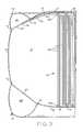
- FIG. 5is an elevation, partial cross-section view taken along line V-V of FIG. 1 , illustrating air pockets and fluid communication channels which cooperate to define the sleeping surface of the mattress;
- FIG. 6is an elevation, partial cross-section view taken along the line VI-VI of FIG. 1 , illustrating a fluid communication channel between the upper peripheral air chamber and upper air chamber of the mattress.
- mattress 10is illustrated in a fully inflated, ready-to-use configuration.
- mattress 10is a “double chamber” type design in which main air chamber 30 defines a majority of the height and overall shape of mattress 10 , and upper air chamber 32 is disposed above main air chamber 30 and provides for the overall structure and feel of upper sleeping surface 40 of mattress 10 .
- mattress 10includes a lower peripheral air chamber 34 extending around the periphery of mattress 10 adjacent a lower, ground contacting surface 42 ( FIG. 3 ).
- Lower peripheral air chamber 34( FIG. 3 ) provides a stable peripheral structure at the base of mattress 10 to prevent an undesirable rolling or buckling of the mattress sidewall, e.g., when a user sits on an edge of upper surface 40 .
- upper peripheral air chamber 36( FIG. 3 ) extends around the outer periphery of upper surface 40 , and provides a raised ridge-like structure to aid in the comfortable retention of a user on upper surface 40 .
- upper peripheral air chamber 36interrupts what might otherwise be a gradual downward sloping of upper surface 40 around the edges of mattress 10 , thereby inhibiting any rolling or buckling the mattress sidewall 16 when a user is near an edge of upper surface 40 .
- a single valve 26 located in one side of mattress 10is used to inflate all of the air chambers 30 , 32 , 34 , 36 of mattress 10 .
- Valve 26places the main air chamber 30 in direct fluid communication with the ambient atmosphere, such that main air chamber 30 can be directly pressurized via valve 26 .
- the lower and upper peripheral air chambers 34 , 36are in secondary fluid communication with the ambient atmosphere, via valve 26 and fluid communication apertures 50 and 52 respectively (as shown in FIG. 4 and further described below), while upper air chamber 32 is in tertiary fluid communication with the ambient atmosphere via apertures 52 and fluid communication channels 54 (shown in FIGS. 1 and 6 and also described further below).
- direct fluid communicationmeans fluid communication across a single barrier, such as a single sidewall formed by one of the various panels which form mattress 10 (further described below).
- Secondary fluid communicationmeans fluid communication which must traverse two spatially separate structures, such as a first panel and a second panel which is spaced from the first panel, or two spaced-apart portions of a single panel.
- tertiary fluid communicationmeans fluid communication which occurs across three spatially separate structures, such as three spatially separate mattress panels or three spaced-apart portions of a single panel, or some combination thereof.
- FIG. 2an exploded view of mattress 10 illustrating its constituent parts is provided.
- the overall internal volume of mattress 10is enclosed by bottom panel 12 , top panel 14 and peripheral panel 16 .
- a lower edge of peripheral panel 16is hermetically bonded to the peripheral edge of bottom panel 12 at weld 60 ( FIG. 1 ), while the opposing upper edge of peripheral panel 16 is hermetically bonded to the peripheral edge of top panel 14 at weld 62 ( FIG. 1 ).
- valve 26When valve 26 is closed, bottom and top panels 12 , 14 cooperate with peripheral panel 16 to define a hermetically sealed internal cavity of mattress 10 including air chambers 30 , 32 , 34 and 36 .
- peripheral panel 16is formed from a strip of material whose ends are bonded at weld 64 .
- welds formed by heating two adjacent materials to a melting or near-melting temperatureare described herein as the method for joining two separate structures of mattress 10 , it is contemplated that other methods, such as adhesive bonding, may also be used.
- each tensioning assembly 18includes a lower weld strip 18 a bonded to bottom panel 12 at weld 66 ( FIG. 3 ), upper weld strip 18 b bonded to lower intermediate panel 22 (shown in FIG. 3 and described in further detail below), and a plurality of tension cords 18 c with lower and upper ends bonded to weld strips 18 a , 18 b respectively.
- mattress 10includes lower peripheral panel 20 , which cooperates with bottom panel 12 and peripheral panel 16 to define lower peripheral air chamber 34 .
- lower peripheral panel 20is formed as a generally rectangular sheet of material having approximately the same outer peripheral dimensions as bottom panel 12 , and has a large central aperture 20 A having a corresponding rectangular shape.
- the outer periphery and central aperture 20 A of panel 20cooperate to define a rectangular strip of material of a substantially constant width around its periphery, as illustrated.
- Lower peripheral panel 20is bonded along its inner peripheral edge to bottom panel 12 at weld 70 , while the outer peripheral edge of panel 20 is affixed to peripheral panel 16 at weld 72 .
- Both of welds 70 and 72extend around the entire periphery of panels 12 , 16 and 20 thereby forming lower peripheral air chamber 34 around the entire lower periphery of mattress 10 .
- lower peripheral air chamber 34is bounded by bottom panel 12 , peripheral panel 16 and lower peripheral panel 20 , in cooperation with welds 60 , 70 and 72 extending around the peripheral extent of mattress 10 .
- lower peripheral panel 20includes fluid communication apertures 50 , as shown in FIG. 2 .
- apertures 50are provided at each of the four corners of the rectangular shape of panel 20 , in order to promote even air inflows during inflation to the entire periphery of peripheral air chamber 34 .
- additional fluid communication apertures 50may be provided, or that as few as one aperture 50 may be provided as required or desired for a particular application.
- aperture 50allows for the flow F 1 of fluid (e.g., air) from main air chamber 30 to lower peripheral air chamber 34 during inflation of mattress 10 , as well as a reverse fluid flow from chamber 34 to chamber 30 during deflation.
- fluide.g., air
- Upper air chamber 32 and upper peripheral air chamber 36are bounded by one or both of lower and upper intermediate panels 22 and 24 , shown in FIG. 2 , in cooperation with top panel 14 and peripheral panel 16 .
- Upper intermediate panel 24has an outer periphery defining a size and shape substantially the same as top panel 14 , i.e., generally rectangular. The outer peripheral edge of upper intermediate panel 24 is affixed to peripheral panel 16 , as shown in FIG. 3 , along weld 74 , which extends around the entire periphery of upper intermediate panel 24 and peripheral panel 16 , in similar fashion to weld 72 between lower peripheral panel 20 and peripheral panel 16 as described above.
- Upper intermediate panel 24further defines an interior weld path 76 a as shown in FIG. 2 , which is a location spaced substantially evenly inwardly from the outer periphery of panel 24 where weld 76 provides affixation of panel 24 to top panel 14 ( FIG. 3 ).
- Upper peripheral air chamber 36is bounded by top panel 14 , peripheral mattress panel 16 and upper intermediate panel 24 , in cooperation with welds 62 , 74 and 76 extending around the peripheral extent of mattress 10 . Similar to lower peripheral panel 20 , upper intermediate panel 24 includes fluid communication apertures 52 at each corner thereof, as shown in FIG. 2 . Apertures 52 allow secondary fluid communication between main air chamber 30 and upper peripheral air chamber 36 , in the form of fluid flow F 2 ( FIG. 4 ).
- Upper air chamber 32is disposed beneath top panel 14 , and is generally bounded by top panel 14 at its upper end and upper intermediate panel 24 at is lower end (see, e.g., FIG. 5 ).
- Weld 76forms the peripheral boundary of upper air chamber 32 .
- weld 76is interrupted at one or more locations, illustratively two mutually opposed locations, in order to form fluid communication channels 54 ( FIG. 6 ) to facilitate fluid flow from upper peripheral air chamber 36 to upper air chamber 32 .
- Lower intermediate panel 22has a shape which generally corresponds to the shape of upper intermediate panel 24 , except lower intermediate panel 22 is somewhat smaller.
- the outer edge of lower intermediate panel 22is affixed to a lower surface of upper intermediate panel 24 at weld 78 , which extends around the entire periphery of lower intermediate panel 22 and is inset from the outer periphery of upper intermediate panel 24 .
- this insetis substantially constant around the entire outer periphery of panels 22 , 24 .
- weld 78may be located between weld 74 and weld 76 , both horizontally and vertically. As noted above and illustrated in FIG.
- upper weld strips 18 b of tensioning assemblies 18are affixed to lower intermediate panel 22 via welds 68 .
- the presence of lower intermediate panel 22allows welds 68 to be made at a material interface not in direct contact or physical abutment with a majority of sleeping surface 40 , such that any surface irregularities which might result from the presence of welds 68 will not be felt by a user of mattress 10 .
- upper intermediate panel 24is shown as a single, monolithic sheet of material, it is contemplated that other arrangements could be utilized within the scope of the present disclosure.
- upper intermediate panelcould be formed from a strip of material cut into a rectangular shape, similar to bottom panel 12 , with a central panel similar to lower intermediate panel 22 bonded to the interior periphery of the strip to fill in its aperture.
- sleeping surface 40 of upper air chamber 32has a “quilted” pattern appearance arising from a plurality of zigzag welds 80 arranged as illustrated. Further depiction and graphical description of an exemplary form of zigzag welds 80 can be found in U.S. Design application Ser. No. 29/502,063, filed Sep. 11, 2014 and entitled “Inflatable Mattress”, which is commonly assigned with the present application, the entire disclosure of which is hereby incorporated by reference herein.
- upper air chamber 32is formed in the space between top panel 14 and upper intermediate panel 24 , and within the boundary circumscribed by upper weld 76 between panels 14 and 24 ( FIG. 1 ).
- Pressurized fluide.g., air
- fluid communication channels 54formed by a pair of mutually opposed interruptions in weld 76 .
- air entering through valve 26flows into main air chamber 30 , and then into upper peripheral air chamber 36 via fluid communication apertures 52 .
- pressurized airoccupies upper peripheral air chamber 36 , it is allowed to flow through channels 54 into upper air chamber 32 .
- upper air chamber 32is in tertiary fluid communication with valve 26 , because air arriving to upper air chamber 32 flows from valve 26 via main air chamber 30 and upper peripheral air chamber 36 .
- upper peripheral air chamber 36is in secondary fluid communication with valve 26 while main air chamber 30 is in direct fluid communication therewith.
- zigzag welds 80are formed within the boundary of upper air chamber 32 established by the peripheral weld 76 .
- Zigzag welds 80each define alternating lateral and longitudinal sections joined by respective radiused transitions. Neighboring pairs of these radiused transitions are arranged facing one another such that neighboring pairs of zigzag welds 80 form pockets 44 substantially bounded by mutually opposed pairs of lateral and longitudinal weld sections, as illustrated.
- Each of pockets 44presents a generally rectangular appearance with two opposing open corners adjacent the radiused transitions of welds 80 . These opposing corners cooperate to define pocket fluid channels 46 ( FIG. 5 ), which allow air to flow diagonally between adjacent pockets 44 through a gap between neighboring welds 80 .
- sleeping surface 40is defined by a quilted arrangement of inflated pockets 44 , all of which are relatively flat and spaced away from lower intermediate panel 22 and its welds 68 (described in further detail above).
- upper peripheral air chamber 36provides a ridged boundary around the periphery of sleeping surface 40 , presenting a physical barrier to any downward slope of sleeping surface 40 around the edges of mattress 10 , thereby providing stability and security for users of mattress 10 .
Landscapes
- Mattresses And Other Support Structures For Chairs And Beds (AREA)
- Invalid Beds And Related Equipment (AREA)
Abstract
Description
Claims (21)
Priority Applications (1)
| Application Number | Priority Date | Filing Date | Title |
|---|---|---|---|
| US15/006,709US10398235B2 (en) | 2014-01-17 | 2016-01-26 | Multi-chamber inflatable device |
Applications Claiming Priority (6)
| Application Number | Priority Date | Filing Date | Title |
|---|---|---|---|
| CN201420029512.6UCN203735815U (en) | 2013-08-22 | 2014-01-17 | Double air chamber layer type inflatable bed structure |
| CN201420029512U | 2014-01-17 | ||
| CN201420029512.6 | 2014-01-17 | ||
| US29/502,063USD765443S1 (en) | 2014-08-07 | 2014-09-11 | Inflatable mattress |
| US14/599,091US9247827B2 (en) | 2014-01-17 | 2015-01-16 | Multi-chamber inflatable device |
| US15/006,709US10398235B2 (en) | 2014-01-17 | 2016-01-26 | Multi-chamber inflatable device |
Related Parent Applications (1)
| Application Number | Title | Priority Date | Filing Date |
|---|---|---|---|
| US14/599,091ContinuationUS9247827B2 (en) | 2014-01-17 | 2015-01-16 | Multi-chamber inflatable device |
Publications (3)
| Publication Number | Publication Date |
|---|---|
| US20160183692A1 US20160183692A1 (en) | 2016-06-30 |
| US20170215599A2 US20170215599A2 (en) | 2017-08-03 |
| US10398235B2true US10398235B2 (en) | 2019-09-03 |
Family
ID=53543726
Family Applications (2)
| Application Number | Title | Priority Date | Filing Date |
|---|---|---|---|
| US14/599,091ActiveUS9247827B2 (en) | 2014-01-17 | 2015-01-16 | Multi-chamber inflatable device |
| US15/006,709Active2036-04-11US10398235B2 (en) | 2014-01-17 | 2016-01-26 | Multi-chamber inflatable device |
Family Applications Before (1)
| Application Number | Title | Priority Date | Filing Date |
|---|---|---|---|
| US14/599,091ActiveUS9247827B2 (en) | 2014-01-17 | 2015-01-16 | Multi-chamber inflatable device |
Country Status (2)
| Country | Link |
|---|---|
| US (2) | US9247827B2 (en) |
| EP (1) | EP3078301B1 (en) |
Cited By (11)
| Publication number | Priority date | Publication date | Assignee | Title |
|---|---|---|---|---|
| US10687634B1 (en)* | 2019-09-10 | 2020-06-23 | GM Global Technology Operations LLC | Internally tensioned inflatable structures |
| US11014619B2 (en) | 2019-09-10 | 2021-05-25 | GM Global Technology Operations LLC | Internally-tensioned inflatable device for active flow control drag reduction or stability increase |
| US11084541B2 (en) | 2019-09-10 | 2021-08-10 | GM Global Technology Operations LLC | Internally tensioned inflatable structures |
| US11311115B2 (en)* | 2020-06-08 | 2022-04-26 | Jiangsu Jilong Sport and Leisure Products Co., Ltd. | Inflatable bed |
| US11324336B1 (en)* | 2021-09-29 | 2022-05-10 | Fuzhou Nianyue Investment Consulting Co., Ltd | Air cushion bed |
| USD979984S1 (en) | 2021-10-13 | 2023-03-07 | Dongguan Hongyu Plactic Co., Ltd | Airbed |
| US11614083B2 (en) | 2019-09-10 | 2023-03-28 | GM Global Technology Operations LLC | Internally tensioned inflatable structure that is posable in multiple positions |
| US12082702B1 (en)* | 2023-07-29 | 2024-09-10 | Wuzhou Baofeng Plastic Products Co., Ltd. | Inflatable bed with mesh-shaped inclined diaphragm |
| US12102235B1 (en)* | 2024-03-15 | 2024-10-01 | Xiaoyao Luo | Anti-collapse inflatable air mattress |
| US12108880B2 (en)* | 2023-03-07 | 2024-10-08 | Dongguan Hongyu Plastic Co., Ltd | Inflatable bed |
| US20250221545A1 (en)* | 2024-01-10 | 2025-07-10 | Wangli Plastic & Electronics (Huizhou) Co., Ltd. | Multi-layer and multi-chamber inflatable mattress |
Families Citing this family (24)
| Publication number | Priority date | Publication date | Assignee | Title |
|---|---|---|---|---|
| US9247827B2 (en) | 2014-01-17 | 2016-02-02 | Intex Recreation Corp. | Multi-chamber inflatable device |
| USD765443S1 (en)* | 2014-08-07 | 2016-09-06 | Intex Marketing Ltd. | Inflatable mattress |
| CN104473498B (en)* | 2014-10-31 | 2018-07-06 | 先驱塑胶电子(惠州)有限公司 | A kind of backrest conjoined pneumatic bed |
| US10136735B2 (en) | 2014-11-19 | 2018-11-27 | Polygroup Macau Limited (Bvi) | Systems and methods for air mattress temperature control |
| US10327563B2 (en) | 2015-05-11 | 2019-06-25 | Polygroup Macau Limited (Bvi) | Systems and methods for internal airbed structure |
| USD823028S1 (en)* | 2015-12-01 | 2018-07-17 | Intex Marketing Ltd. | Inflatable mattress |
| EP3192401B1 (en)* | 2016-01-13 | 2018-09-19 | Bestway Inflatables & Material Corp | Inflatable bed |
| CN105615393A (en)* | 2016-02-23 | 2016-06-01 | 浙江大自然旅游用品有限公司 | Air inflation product and air inflation product welding process |
| US10582778B2 (en) | 2016-08-01 | 2020-03-10 | Polygroup Macau Limited (Bvi) | Inflatable airbed mattress internal support system |
| US10863831B2 (en) | 2016-08-01 | 2020-12-15 | Polygroup Macau Limited (Bvi) | Systems and methods for air mattress pressure control |
| USD910338S1 (en)* | 2018-08-14 | 2021-02-16 | Shanghai Jilong Plastic Products Co., Ltd. | Airbed |
| USD898458S1 (en)* | 2018-12-03 | 2020-10-13 | Jianqiang Huang | Inflatable mattress |
| CN209807775U (en) | 2018-12-18 | 2019-12-20 | 贝尔格莱维亚伍德有限公司 | Inflatable air cushion |
| US10986937B2 (en)* | 2018-12-27 | 2021-04-27 | Evermax Eco Industry Ltd. | Structure of inflatable bed |
| CN110680113B (en)* | 2019-11-01 | 2024-10-11 | 旺利塑胶电子(惠州)有限公司 | Multi-air-chamber inflatable bed |
| US12075917B2 (en)* | 2019-12-05 | 2024-09-03 | Dongguan Hongyu Plastic Co., Ltd | Inflatable bed |
| USD982359S1 (en)* | 2019-12-10 | 2023-04-04 | Dongguan Hongyu Plastic Co., Ltd | Air mattress |
| CN112741450A (en)* | 2021-01-30 | 2021-05-04 | 湖南长锦成电器有限公司 | Air mattress |
| US11937703B2 (en)* | 2021-09-24 | 2024-03-26 | Dongguan Hongyu Plastic Co., Ltd. | Inflatable bed with gas delivery pipe |
| WO2023045102A1 (en)* | 2021-09-24 | 2023-03-30 | 东莞市红宇塑胶有限公司 | Inflatable bed |
| CN218500349U (en)* | 2021-10-29 | 2023-02-21 | 上海荣威塑胶工业有限公司 | Side embossed inflatable product |
| CN115610361A (en)* | 2022-11-10 | 2023-01-17 | 叶飞 | A car inflatable lifesaving cushion |
| USD1002241S1 (en)* | 2022-12-12 | 2023-10-24 | Zhejiang Natural Outdoor Goods Inc. | Air mattress |
| CN220713473U (en)* | 2023-08-10 | 2024-04-05 | 东莞市红宇塑胶有限公司 | Inflatable bed |
Citations (47)
| Publication number | Priority date | Publication date | Assignee | Title |
|---|---|---|---|---|
| US486696A (en) | 1891-10-01 | 1892-11-22 | curlol | |
| US1371919A (en) | 1920-10-08 | 1921-03-15 | Eugene P Mahony | Vermin-proof combined mattress and spring |
| US1625810A (en) | 1925-02-27 | 1927-04-26 | Krichbaum Ora | Method of making alpha rubber article |
| GB313023A (en) | 1928-03-01 | 1929-06-04 | Avon India Rubber Company Ltd | Improvements in or relating to air cushions or the like |
| US2318492A (en) | 1941-01-16 | 1943-05-04 | John H Johnson | Air mattress |
| US2604641A (en) | 1947-02-11 | 1952-07-29 | Stanley F Reed | Inflatable mattress |
| US2753573A (en) | 1951-11-08 | 1956-07-10 | Edward D Barker | Inflatable mattress |
| US3286285A (en) | 1964-11-23 | 1966-11-22 | Jr James I Harvey | Air mattress and hammock combination |
| US3705429A (en) | 1969-01-09 | 1972-12-12 | Walter P Nail | Inflatable load supporting structures |
| US4167432A (en) | 1978-04-07 | 1979-09-11 | Mollura Carlos A | Process of making a water bed mattress |
| US4389742A (en) | 1981-01-02 | 1983-06-28 | Dewitt Nick R | Pressure controlled air/water cushion |
| US4405129A (en) | 1980-04-17 | 1983-09-20 | Stuckey John | Therapeutic exercise device |
| US4483030A (en) | 1982-05-03 | 1984-11-20 | Medisearch Pr, Inc. | Air pad |
| US4547919A (en) | 1983-02-17 | 1985-10-22 | Cheng Chung Wang | Inflatable article with reforming and reinforcing structure |
| US4631767A (en) | 1984-11-21 | 1986-12-30 | Kcj Corporation | Air flotation mattress |
| US5022109A (en) | 1990-06-11 | 1991-06-11 | Dielectrics Industries | Inflatable bladder |
| US5044030A (en) | 1990-06-06 | 1991-09-03 | Fabrico Manufacturing Corporation | Multiple layer fluid-containing cushion |
| US5109560A (en) | 1991-09-18 | 1992-05-05 | Keisei Medical Industrial Co., Ltd. | Ventilated air mattress with alternately inflatable air cells having communicating upper and lower air chambers |
| US5408711A (en) | 1994-05-17 | 1995-04-25 | Mcclelland; Marion | Air mattress assembly |
| US5561873A (en) | 1994-07-15 | 1996-10-08 | Patient Transfer Systems, Inc. | Air chamber-type patient mover air pallet with multiple control features |
| US5598593A (en) | 1995-02-10 | 1997-02-04 | Aqua-Leisure Industries, Inc. | Inflatable air bed |
| US5604945A (en) | 1995-06-16 | 1997-02-25 | Intex Recreation Corp. | Inflatable mattress |
| US5642544A (en) | 1994-10-14 | 1997-07-01 | Munoz; Rosario Castro | Hydraulic pillow |
| US5890245A (en) | 1996-11-05 | 1999-04-06 | Therapy Concepts, Inc. | Disposable ventilating mattress and method of making same |
| USD414365S (en) | 1998-02-27 | 1999-09-28 | Intex Recreation Corp. | Quilt beam mattress |
| USD414644S (en) | 1998-02-27 | 1999-10-05 | Intex Recreation Corp. | Wave beam mattress |
| US5960495A (en) | 1998-02-27 | 1999-10-05 | Intex Recreation Corp. | Quilt beam mattress |
| US6016582A (en) | 1998-07-17 | 2000-01-25 | Larson; Lynn D. | Air support pillow top assembly |
| US6073291A (en) | 1997-02-21 | 2000-06-13 | Davis; David T. | Inflatable medical patient transfer apparatus |
| US6076214A (en) | 1998-08-11 | 2000-06-20 | Sevylor U.S.A., Inc. | Inflatable mattress assemblies |
| US6546580B2 (en) | 2000-10-31 | 2003-04-15 | Molten Corporation | Air mattress |
| US6568011B2 (en) | 2001-01-04 | 2003-05-27 | Intex Recreation Corp. | Inflatable mattress |
| US6618884B1 (en) | 2002-07-11 | 2003-09-16 | Hsin-Tsai Wu | Inflatable mattress with integrated upper and lower inflatable bodies |
| US20030188388A1 (en) | 2002-04-08 | 2003-10-09 | Aero Products International, Inc. | Pillow top inflatable mattress |
| US7089618B1 (en) | 2003-06-18 | 2006-08-15 | The Coleman Company, Inc. | Air mattress |
| US20070124864A1 (en)* | 2005-12-07 | 2007-06-07 | Lau Vincent W | Inflatable mattress assembly |
| US7254853B1 (en)* | 2006-04-13 | 2007-08-14 | Worl Sung Kim | Air mattress |
| US7269866B2 (en)* | 2005-04-04 | 2007-09-18 | Bestway (Usa) Inc. | Air bed with stable supporting structure |
| US20070283499A1 (en) | 2006-06-08 | 2007-12-13 | Intex Recreation Corp. | Air-inflated mattress |
| US20080148488A1 (en) | 2006-12-26 | 2008-06-26 | Hsin-Tsai Wu | Inflatable pad with recreation function |
| US20090165211A1 (en) | 2007-11-07 | 2009-07-02 | Rong-Jyh Song | Inflatable Bed |
| US7610642B2 (en) | 2001-03-30 | 2009-11-03 | Dennis Boyd | Air mattress with pillow top |
| US20090320211A1 (en) | 2007-10-16 | 2009-12-31 | Lau Vincent W S | Inflatable bed with cushion cells |
| US20130180052A1 (en)* | 2011-12-13 | 2013-07-18 | Apex Billion Int'l Inv. Ltd. | Air mattress |
| US8661590B2 (en) | 2011-12-13 | 2014-03-04 | Apex Billion Int'l Inv. Ltd. | Air mattress |
| US20150096126A1 (en)* | 2013-10-08 | 2015-04-09 | Swo-Chung Chai | Structure of inflatable mattress |
| US9247827B2 (en) | 2014-01-17 | 2016-02-02 | Intex Recreation Corp. | Multi-chamber inflatable device |
- 2015
- 2015-01-16USUS14/599,091patent/US9247827B2/enactiveActive
- 2016
- 2016-01-15EPEP16151605.9Apatent/EP3078301B1/enactiveActive
- 2016-01-26USUS15/006,709patent/US10398235B2/enactiveActive
Patent Citations (50)
| Publication number | Priority date | Publication date | Assignee | Title |
|---|---|---|---|---|
| US486696A (en) | 1891-10-01 | 1892-11-22 | curlol | |
| US1371919A (en) | 1920-10-08 | 1921-03-15 | Eugene P Mahony | Vermin-proof combined mattress and spring |
| US1625810A (en) | 1925-02-27 | 1927-04-26 | Krichbaum Ora | Method of making alpha rubber article |
| US1793703A (en) | 1925-02-27 | 1931-02-24 | Krichbaum Ora | Rubber article |
| GB313023A (en) | 1928-03-01 | 1929-06-04 | Avon India Rubber Company Ltd | Improvements in or relating to air cushions or the like |
| US2318492A (en) | 1941-01-16 | 1943-05-04 | John H Johnson | Air mattress |
| US2604641A (en) | 1947-02-11 | 1952-07-29 | Stanley F Reed | Inflatable mattress |
| US2753573A (en) | 1951-11-08 | 1956-07-10 | Edward D Barker | Inflatable mattress |
| US3286285A (en) | 1964-11-23 | 1966-11-22 | Jr James I Harvey | Air mattress and hammock combination |
| US3705429A (en) | 1969-01-09 | 1972-12-12 | Walter P Nail | Inflatable load supporting structures |
| US4167432A (en) | 1978-04-07 | 1979-09-11 | Mollura Carlos A | Process of making a water bed mattress |
| US4405129A (en) | 1980-04-17 | 1983-09-20 | Stuckey John | Therapeutic exercise device |
| US4389742A (en) | 1981-01-02 | 1983-06-28 | Dewitt Nick R | Pressure controlled air/water cushion |
| US4483030A (en) | 1982-05-03 | 1984-11-20 | Medisearch Pr, Inc. | Air pad |
| US4547919A (en) | 1983-02-17 | 1985-10-22 | Cheng Chung Wang | Inflatable article with reforming and reinforcing structure |
| US4631767A (en) | 1984-11-21 | 1986-12-30 | Kcj Corporation | Air flotation mattress |
| US5044030A (en) | 1990-06-06 | 1991-09-03 | Fabrico Manufacturing Corporation | Multiple layer fluid-containing cushion |
| US5022109A (en) | 1990-06-11 | 1991-06-11 | Dielectrics Industries | Inflatable bladder |
| US5109560A (en) | 1991-09-18 | 1992-05-05 | Keisei Medical Industrial Co., Ltd. | Ventilated air mattress with alternately inflatable air cells having communicating upper and lower air chambers |
| US5408711A (en) | 1994-05-17 | 1995-04-25 | Mcclelland; Marion | Air mattress assembly |
| US5561873A (en) | 1994-07-15 | 1996-10-08 | Patient Transfer Systems, Inc. | Air chamber-type patient mover air pallet with multiple control features |
| US5642544A (en) | 1994-10-14 | 1997-07-01 | Munoz; Rosario Castro | Hydraulic pillow |
| US5598593A (en) | 1995-02-10 | 1997-02-04 | Aqua-Leisure Industries, Inc. | Inflatable air bed |
| US5604945A (en) | 1995-06-16 | 1997-02-25 | Intex Recreation Corp. | Inflatable mattress |
| US5890245A (en) | 1996-11-05 | 1999-04-06 | Therapy Concepts, Inc. | Disposable ventilating mattress and method of making same |
| US6073291A (en) | 1997-02-21 | 2000-06-13 | Davis; David T. | Inflatable medical patient transfer apparatus |
| USD414365S (en) | 1998-02-27 | 1999-09-28 | Intex Recreation Corp. | Quilt beam mattress |
| USD414644S (en) | 1998-02-27 | 1999-10-05 | Intex Recreation Corp. | Wave beam mattress |
| US5960495A (en) | 1998-02-27 | 1999-10-05 | Intex Recreation Corp. | Quilt beam mattress |
| US6016582A (en) | 1998-07-17 | 2000-01-25 | Larson; Lynn D. | Air support pillow top assembly |
| US6076214A (en) | 1998-08-11 | 2000-06-20 | Sevylor U.S.A., Inc. | Inflatable mattress assemblies |
| US6546580B2 (en) | 2000-10-31 | 2003-04-15 | Molten Corporation | Air mattress |
| US6568011B2 (en) | 2001-01-04 | 2003-05-27 | Intex Recreation Corp. | Inflatable mattress |
| US7610642B2 (en) | 2001-03-30 | 2009-11-03 | Dennis Boyd | Air mattress with pillow top |
| US20030188388A1 (en) | 2002-04-08 | 2003-10-09 | Aero Products International, Inc. | Pillow top inflatable mattress |
| US6618884B1 (en) | 2002-07-11 | 2003-09-16 | Hsin-Tsai Wu | Inflatable mattress with integrated upper and lower inflatable bodies |
| US7089618B1 (en) | 2003-06-18 | 2006-08-15 | The Coleman Company, Inc. | Air mattress |
| US7269866B2 (en)* | 2005-04-04 | 2007-09-18 | Bestway (Usa) Inc. | Air bed with stable supporting structure |
| US20070124864A1 (en)* | 2005-12-07 | 2007-06-07 | Lau Vincent W | Inflatable mattress assembly |
| US7353555B2 (en) | 2005-12-07 | 2008-04-08 | Ideal Time Consultants Limited | Inflatable mattress assembly |
| US7254853B1 (en)* | 2006-04-13 | 2007-08-14 | Worl Sung Kim | Air mattress |
| US7591036B2 (en)* | 2006-06-08 | 2009-09-22 | Intex Recreation Corp. | Air-inflated mattress |
| US20070283499A1 (en) | 2006-06-08 | 2007-12-13 | Intex Recreation Corp. | Air-inflated mattress |
| US20080148488A1 (en) | 2006-12-26 | 2008-06-26 | Hsin-Tsai Wu | Inflatable pad with recreation function |
| US20090320211A1 (en) | 2007-10-16 | 2009-12-31 | Lau Vincent W S | Inflatable bed with cushion cells |
| US20090165211A1 (en) | 2007-11-07 | 2009-07-02 | Rong-Jyh Song | Inflatable Bed |
| US20130180052A1 (en)* | 2011-12-13 | 2013-07-18 | Apex Billion Int'l Inv. Ltd. | Air mattress |
| US8661590B2 (en) | 2011-12-13 | 2014-03-04 | Apex Billion Int'l Inv. Ltd. | Air mattress |
| US20150096126A1 (en)* | 2013-10-08 | 2015-04-09 | Swo-Chung Chai | Structure of inflatable mattress |
| US9247827B2 (en) | 2014-01-17 | 2016-02-02 | Intex Recreation Corp. | Multi-chamber inflatable device |
Non-Patent Citations (1)
| Title |
|---|
| Beautyrest Countour Aire Mattress, available at least as early as Jul. 22, 2013, 1 page. |
Cited By (11)
| Publication number | Priority date | Publication date | Assignee | Title |
|---|---|---|---|---|
| US10687634B1 (en)* | 2019-09-10 | 2020-06-23 | GM Global Technology Operations LLC | Internally tensioned inflatable structures |
| US11014619B2 (en) | 2019-09-10 | 2021-05-25 | GM Global Technology Operations LLC | Internally-tensioned inflatable device for active flow control drag reduction or stability increase |
| US11084541B2 (en) | 2019-09-10 | 2021-08-10 | GM Global Technology Operations LLC | Internally tensioned inflatable structures |
| US11614083B2 (en) | 2019-09-10 | 2023-03-28 | GM Global Technology Operations LLC | Internally tensioned inflatable structure that is posable in multiple positions |
| US11311115B2 (en)* | 2020-06-08 | 2022-04-26 | Jiangsu Jilong Sport and Leisure Products Co., Ltd. | Inflatable bed |
| US11324336B1 (en)* | 2021-09-29 | 2022-05-10 | Fuzhou Nianyue Investment Consulting Co., Ltd | Air cushion bed |
| USD979984S1 (en) | 2021-10-13 | 2023-03-07 | Dongguan Hongyu Plactic Co., Ltd | Airbed |
| US12108880B2 (en)* | 2023-03-07 | 2024-10-08 | Dongguan Hongyu Plastic Co., Ltd | Inflatable bed |
| US12082702B1 (en)* | 2023-07-29 | 2024-09-10 | Wuzhou Baofeng Plastic Products Co., Ltd. | Inflatable bed with mesh-shaped inclined diaphragm |
| US20250221545A1 (en)* | 2024-01-10 | 2025-07-10 | Wangli Plastic & Electronics (Huizhou) Co., Ltd. | Multi-layer and multi-chamber inflatable mattress |
| US12102235B1 (en)* | 2024-03-15 | 2024-10-01 | Xiaoyao Luo | Anti-collapse inflatable air mattress |
Also Published As
| Publication number | Publication date |
|---|---|
| US20150201760A1 (en) | 2015-07-23 |
| EP3078301A1 (en) | 2016-10-12 |
| US9247827B2 (en) | 2016-02-02 |
| US20160183692A1 (en) | 2016-06-30 |
| US20170215599A2 (en) | 2017-08-03 |
| EP3078301B1 (en) | 2020-03-11 |
Similar Documents
| Publication | Publication Date | Title |
|---|---|---|
| US10398235B2 (en) | Multi-chamber inflatable device | |
| US11564505B2 (en) | Inflatable bed | |
| US11857078B2 (en) | Inflatable airbed mattress internal support system | |
| US6973690B2 (en) | Adjustable inflatable pillow | |
| US6463610B1 (en) | Multi-chamber airbed | |
| US7337485B2 (en) | Double high airbed utilizing coils | |
| US5960495A (en) | Quilt beam mattress | |
| US5974608A (en) | Camping mattress with cradling cushions | |
| EP1795089B1 (en) | Inflatable mattress assembly | |
| US20090085393A1 (en) | Inflatable Chair With Cushion Top | |
| US11730279B2 (en) | Portable mattress with drop-stitch inflatable chamber | |
| US20150296993A1 (en) | Mattress assembly | |
| US20070214575A1 (en) | Method of constructing an inflatable support system having thermoplastic polyurethane constuction | |
| CN204232695U (en) | A kind of air mattress with separation layer | |
| WO2015023932A1 (en) | Mesh beam structure for inflatable product | |
| US5086528A (en) | Water mattress and method for making same | |
| EP3174438B1 (en) | Air mattress and method of constructing same | |
| NZ780706A (en) | Pet bed |
Legal Events
| Date | Code | Title | Description |
|---|---|---|---|
| AS | Assignment | Owner name:INTEX MARKETING LTD., VIRGIN ISLANDS, BRITISH Free format text:ASSIGNMENT OF ASSIGNORS INTEREST;ASSIGNOR:INTEX RECREATION CORP.;REEL/FRAME:038336/0844 Effective date:20160418 | |
| AS | Assignment | Owner name:INTEX INDUSTRIES XIAMEN CO. LTD, CHINA Free format text:ASSIGNMENT OF ASSIGNORS INTEREST;ASSIGNORS:LIN, HUA HSIANG;HSU, YAW YUAN;REEL/FRAME:039912/0123 Effective date:20141205 Owner name:INTEX RECREATION CORP., CALIFORNIA Free format text:ASSIGNMENT OF ASSIGNORS INTEREST;ASSIGNOR:INTEX INDUSTRIES XIAMEN CO. LTD.;REEL/FRAME:039912/0424 Effective date:20141205 | |
| STPP | Information on status: patent application and granting procedure in general | Free format text:DOCKETED NEW CASE - READY FOR EXAMINATION | |
| STPP | Information on status: patent application and granting procedure in general | Free format text:NOTICE OF ALLOWANCE MAILED -- APPLICATION RECEIVED IN OFFICE OF PUBLICATIONS | |
| STPP | Information on status: patent application and granting procedure in general | Free format text:PUBLICATIONS -- ISSUE FEE PAYMENT RECEIVED | |
| STPP | Information on status: patent application and granting procedure in general | Free format text:PUBLICATIONS -- ISSUE FEE PAYMENT VERIFIED | |
| STCF | Information on status: patent grant | Free format text:PATENTED CASE | |
| CC | Certificate of correction | ||
| MAFP | Maintenance fee payment | Free format text:PAYMENT OF MAINTENANCE FEE, 4TH YEAR, LARGE ENTITY (ORIGINAL EVENT CODE: M1551); ENTITY STATUS OF PATENT OWNER: LARGE ENTITY Year of fee payment:4 |