US10392830B2 - Clevis sensing lock - Google Patents
Clevis sensing lockDownload PDFInfo
- Publication number
- US10392830B2 US10392830B2US15/510,139US201515510139AUS10392830B2US 10392830 B2US10392830 B2US 10392830B2US 201515510139 AUS201515510139 AUS 201515510139AUS 10392830 B2US10392830 B2US 10392830B2
- Authority
- US
- United States
- Prior art keywords
- clevis
- lock
- handle
- lock member
- sensing
- Prior art date
- Legal status (The legal status is an assumption and is not a legal conclusion. Google has not performed a legal analysis and makes no representation as to the accuracy of the status listed.)
- Active, expires
Links
Images


Classifications
- E—FIXED CONSTRUCTIONS
- E05—LOCKS; KEYS; WINDOW OR DOOR FITTINGS; SAFES
- E05B—LOCKS; ACCESSORIES THEREFOR; HANDCUFFS
- E05B13/00—Devices preventing the key or the handle or both from being used
- E05B13/10—Devices preventing the key or the handle or both from being used formed by a lock arranged in the handle
- E—FIXED CONSTRUCTIONS
- E05—LOCKS; KEYS; WINDOW OR DOOR FITTINGS; SAFES
- E05B—LOCKS; ACCESSORIES THEREFOR; HANDCUFFS
- E05B27/00—Cylinder locks or other locks with tumbler pins or balls that are set by pushing the key in
- E05B27/0046—Axially movable rotor
- E—FIXED CONSTRUCTIONS
- E05—LOCKS; KEYS; WINDOW OR DOOR FITTINGS; SAFES
- E05B—LOCKS; ACCESSORIES THEREFOR; HANDCUFFS
- E05B15/00—Other details of locks; Parts for engagement by bolts of fastening devices
- E05B15/02—Striking-plates; Keepers; Bolt staples; Escutcheons
- E05B15/0205—Striking-plates, keepers, staples
- E—FIXED CONSTRUCTIONS
- E05—LOCKS; KEYS; WINDOW OR DOOR FITTINGS; SAFES
- E05B—LOCKS; ACCESSORIES THEREFOR; HANDCUFFS
- E05B27/00—Cylinder locks or other locks with tumbler pins or balls that are set by pushing the key in
- E05B27/0003—Details
- E—FIXED CONSTRUCTIONS
- E05—LOCKS; KEYS; WINDOW OR DOOR FITTINGS; SAFES
- E05B—LOCKS; ACCESSORIES THEREFOR; HANDCUFFS
- E05B27/00—Cylinder locks or other locks with tumbler pins or balls that are set by pushing the key in
- E05B27/0003—Details
- E05B27/0017—Tumblers or pins
- E—FIXED CONSTRUCTIONS
- E05—LOCKS; KEYS; WINDOW OR DOOR FITTINGS; SAFES
- E05B—LOCKS; ACCESSORIES THEREFOR; HANDCUFFS
- E05B27/00—Cylinder locks or other locks with tumbler pins or balls that are set by pushing the key in
- E05B27/0032—Cylinder locks or other locks with tumbler pins or balls that are set by pushing the key in with both axially and radially arranged tumbler pins or balls
- E—FIXED CONSTRUCTIONS
- E05—LOCKS; KEYS; WINDOW OR DOOR FITTINGS; SAFES
- E05B—LOCKS; ACCESSORIES THEREFOR; HANDCUFFS
- E05B27/00—Cylinder locks or other locks with tumbler pins or balls that are set by pushing the key in
- E05B27/02—Cylinder locks or other locks with tumbler pins or balls that are set by pushing the key in operated by the edge of the key
- E05B27/08—Cylinder locks or other locks with tumbler pins or balls that are set by pushing the key in operated by the edge of the key arranged axially
- E05B27/083—Cylinder locks or other locks with tumbler pins or balls that are set by pushing the key in operated by the edge of the key arranged axially of the split-pin tumbler type
- E—FIXED CONSTRUCTIONS
- E05—LOCKS; KEYS; WINDOW OR DOOR FITTINGS; SAFES
- E05B—LOCKS; ACCESSORIES THEREFOR; HANDCUFFS
- E05B63/00—Locks or fastenings with special structural characteristics
- E05B63/12—Locks or fastenings with special structural characteristics with means carried by the bolt for interlocking with the keeper
- E—FIXED CONSTRUCTIONS
- E05—LOCKS; KEYS; WINDOW OR DOOR FITTINGS; SAFES
- E05B—LOCKS; ACCESSORIES THEREFOR; HANDCUFFS
- E05B63/00—Locks or fastenings with special structural characteristics
- E05B63/18—Locks or fastenings with special structural characteristics with arrangements independent of the locking mechanism for retaining the bolt or latch in the retracted position
- E05B63/185—Preventing actuation of a bolt when the wing is open
- E—FIXED CONSTRUCTIONS
- E05—LOCKS; KEYS; WINDOW OR DOOR FITTINGS; SAFES
- E05C—BOLTS OR FASTENING DEVICES FOR WINGS, SPECIALLY FOR DOORS OR WINDOWS
- E05C19/00—Other devices specially designed for securing wings, e.g. with suction cups
- E05C19/10—Hook fastenings; Fastenings in which a link engages a fixed hook-like member
- E05C19/12—Hook fastenings; Fastenings in which a link engages a fixed hook-like member pivotally mounted around an axis
- E05C19/14—Hook fastenings; Fastenings in which a link engages a fixed hook-like member pivotally mounted around an axis with toggle action
- B—PERFORMING OPERATIONS; TRANSPORTING
- B64—AIRCRAFT; AVIATION; COSMONAUTICS
- B64D—EQUIPMENT FOR FITTING IN OR TO AIRCRAFT; FLIGHT SUITS; PARACHUTES; ARRANGEMENT OR MOUNTING OF POWER PLANTS OR PROPULSION TRANSMISSIONS IN AIRCRAFT
- B64D29/00—Power-plant nacelles, fairings or cowlings
- B64D29/08—Inspection panels for power plants
- E—FIXED CONSTRUCTIONS
- E05—LOCKS; KEYS; WINDOW OR DOOR FITTINGS; SAFES
- E05B—LOCKS; ACCESSORIES THEREFOR; HANDCUFFS
- E05B13/00—Devices preventing the key or the handle or both from being used
- E05B13/002—Devices preventing the key or the handle or both from being used locking the handle
- E—FIXED CONSTRUCTIONS
- E05—LOCKS; KEYS; WINDOW OR DOOR FITTINGS; SAFES
- E05B—LOCKS; ACCESSORIES THEREFOR; HANDCUFFS
- E05B15/00—Other details of locks; Parts for engagement by bolts of fastening devices
- E05B15/02—Striking-plates; Keepers; Bolt staples; Escutcheons
- E05B15/0205—Striking-plates, keepers, staples
- E05B2015/023—Keeper shape
- E—FIXED CONSTRUCTIONS
- E05—LOCKS; KEYS; WINDOW OR DOOR FITTINGS; SAFES
- E05B—LOCKS; ACCESSORIES THEREFOR; HANDCUFFS
- E05B27/00—Cylinder locks or other locks with tumbler pins or balls that are set by pushing the key in
- E05B27/0053—Cylinder locks or other locks with tumbler pins or balls that are set by pushing the key in for use with more than one key, e.g. master-slave key
- E—FIXED CONSTRUCTIONS
- E05—LOCKS; KEYS; WINDOW OR DOOR FITTINGS; SAFES
- E05B—LOCKS; ACCESSORIES THEREFOR; HANDCUFFS
- E05B41/00—Locks with visible indication as to whether the lock is locked or unlocked
- E—FIXED CONSTRUCTIONS
- E05—LOCKS; KEYS; WINDOW OR DOOR FITTINGS; SAFES
- E05C—BOLTS OR FASTENING DEVICES FOR WINGS, SPECIALLY FOR DOORS OR WINDOWS
- E05C19/00—Other devices specially designed for securing wings, e.g. with suction cups
- E05C19/10—Hook fastenings; Fastenings in which a link engages a fixed hook-like member
- E05C19/12—Hook fastenings; Fastenings in which a link engages a fixed hook-like member pivotally mounted around an axis
- E05C19/14—Hook fastenings; Fastenings in which a link engages a fixed hook-like member pivotally mounted around an axis with toggle action
- E05C19/145—Hook fastenings; Fastenings in which a link engages a fixed hook-like member pivotally mounted around an axis with toggle action flush
Definitions
- the present disclosurerelates generally to a latch for an aircraft engine nacelle, and more specifically to a locking mechanism for such a latch.
- a variety of latchesare used on aircraft to retain various components of the aircraft in a locked condition under circumstances such as flight and storage of the aircraft.
- the latchesmust operate to unlock the corresponding panel, cowling or other device from the aircraft.
- the latchis disengaged to allow the cowling to be operated away from the engine components which it houses.
- the cowlingonce opened, allows the aircraft maintenance professional to access the engine components.
- the cowlingis closed.
- the latchis used to lock the cowling in the closed condition to retain the engine components in the housed condition.
- the maintenance professionalmay use a device to “clip” the latches closed to keep them from projecting out from the aircraft body or housing.
- the latchesare clipped in a closed or lower profile position to prevent the latches from becoming bumped or from bumping the maintenance professional. Clipping the latches does not necessarily close or lock the latch but allows the latch to be maintained in a much lower profile against the aircraft housing or body. Since the latches are in a lower profile configuration, they reduce the chance of the maintenance professional bumping into them either with his body or with a piece of equipment. This can be useful to protect the latches as well as the maintenance professional. However, clipped latches can inadvertently appear to be locked and as such may fail to be locked.
- the present disclosureincludes a clevis-sensing lock assembly for use with a latching system.
- the clevis-sensing lockcan be installed into the latching system and provides structures which function to prevent operation of the clevis in the unlocked position.
- a devicesuch as a key or tool is used to unlock the latch and allow it to open.
- the structure and function of the clevis-sensing lockretains this device in the lock to prevent its removal unless the latch is in the fully closed position. Once in the fully closed position the lock can be closed and the device removed. Additionally, an indicator or flag can be added to the device to further enhance the visibility of the locked or unlocked condition of the latch.
- the lockprovides structures which function to interfere with the operation of the clevis until the latch is in the desired closed and confirmed locked position.
- the clevis-sensing lockcan be used with a specially designed latch or retrofitted to be used with a variety of latches.
- the variety of latchescan be remanufactured to provide the same or substantially the same envelope of operation using virtually the same components but replacing portions of the trigger assembly with the lock assembly.
- a latch mechanismincludes a hook-handle assembly, a clevis, and a clevis-sensing lock.
- the hook-handle assemblymay include a hook member, a handle, and a linkage arrangement coupled between the hook member and handle.
- the clevismay include a hook-end receiver and a coupler portion spaced apart from the hook-end receiver to at least partially define an opening therebetween.
- the hook-end receivermay be configured to engage with a hook end of the hook member as the handle moves from an open position extending away from the clevis toward a closed position extending toward the clevis.
- the clevis-sensing lockmay be coupled to the handle to move with the handle.
- the clevis-sensing lockmay include a block, a lock cylinder received in the block and configured to rotate relative to the block, and an interference member coupled to the lock cylinder to rotate with the lock cylinder relative to the block.
- the interference membermay be configured to pass through the opening of the clevis and rotate relative to the block to engage an underside of the clevis and the lock cylinder may be configured to control rotation of the interference member.
- the latch mechanismmay further include a tumbler arrangement coupled between the lock cylinder and the block and configured to control rotation of the lock cylinder relative to the block.
- the tumbler arrangementmay include a detent spring, a detent pin positioned between the lock cylinder and the detent spring, and a tumbler pin positioned between the detent pin and the lock cylinder.
- the detent springmay be configured to bias the detent pin toward the tumbler pin.
- the detent pinmay be configured to engage with the block and the lock cylinder to restrict rotation of the lock cylinder when an interface between the detent pin and the tumbler pin is misaligned from a lower surface of the lock cylinder.
- the latch mechanismmay further include a key configured to be received in the lock cylinder to engage with the tumbler pin and to align the interface between the detent pin and the tumbler pin with the lower surface of the lock cylinder.
- the latch mechanismmay further include a key having a head and a shaft coupled to the head.
- the shaftmay be configured to be received in the lock cylinder to engage with the tumbler arrangement to allow rotation of the lock cylinder and the head may be configured to extend away from the handle to provide an indication of an unlocked state of the clevis-sensing lock.
- the keymay further include a protrusion extending outward from the shaft and configured to engage with the handle to trap the shaft within the lock cylinder when the lock cylinder is rotated relative to the block.
- the lock cylindermay be formed to include an annular groove and an axial slot extending toward the interference member from the annular groove.
- the latch mechanismmay further include a cross-pin configured to slide in the annular groove and axial slot of the lock cylinder to control rotation of the lock cylinder.
- the latch mechanismmay further include the clevis may further include a fin extending from an upper surface clevis opposite the underside.
- the finmay be configured to move the cross-pin out of the axial slot and into the annular groove to allow rotation of the lock cylinder as the handle moves toward the closed position.
- the lock cylindermay be formed to include a groove extending at least partially around a circumference of the lock cylinder.
- a fastenermay extend through the handle and the block to couple the clevis-sensing lock to the handle and may be received in the groove of the lock cylinder.
- the groove of the lock cylindermay be configured to limit rotation of the lock cylinder relative to the block.
- a method of operating a latch mechanismmay include inserting a key into a clevis-sensing lock through an aperture formed in a handle of a hook-handle assembly, rotating the key to disengage an interference member of the clevis-sensing lock from a clevis, moving the handle relative to the clevis to disengage a fin of the clevis from the clevis-sensing lock to engage a cross-pin of the clevis-sensing lock with a lock cylinder of the clevis-sensing lock to block rotation of the key such that the key is trapped in the clevis-sensing lock, and moving the handle to disengage a hook member of the hook-handle assembly from the clevis.
- the methodmay further include moving the handle toward the clevis to engage the hook member with the clevis, moving the handle toward the clevis to engage the fin with the clevis-sensing lock to disengage the cross-pin from the lock cylinder to allow rotation of the key, rotating the key such that the interference member is engaged with an underside of the clevis, and removing the key from the clevis sensing lock.
- inserting the keymay include extending a shaft of the key into the lock cylinder and engaging a tumbler arrangement to allow rotation of the interference member.
- removing the keymay include removing the shaft from the lock cylinder and disengaging the tumbler arrangement to block rotation of the interference member.
- a clevis-sensing lockmay include a block, a lock cylinder, a cross-pin, a tumbler arrangement, a coupler shaft, and an interference member.
- the blockmay be formed to include a cylinder-receiving bore extending into the block and a pin-receiving slot extending into the block to intersect with the cylinder-receiving bore.
- the lock cylindermay be configured to be received in the cylinder-receiving bore of the block and rotate relative to the block.
- the lock cylindermay include a first end and a second end spaced apart from the first end.
- the lock cylindermay be formed to include an annular groove, an axial slot extending toward the first end of the lock cylinder from the annular groove, and a key-receiving bore extending from the second end toward the first end.
- the cross-pinmay be positioned within the pin-receiving slot of the block and configured to slide in the annular groove and axial slot of the lock cylinder to control rotation of the lock cylinder.
- the tumbler arrangementmay be coupled between the lock cylinder and the block and configured to control rotation of the lock cylinder.
- the coupler shaftmay be positioned within the key-receiving bore and coupled with the lock cylinder to rotate therewith.
- the interference membermay be coupled to the coupler shaft at the first end of the lock cylinder to rotate with the lock cylinder.
- the clevis-sensing lockmay further include a guide pin having a head and a hole extending through the head.
- the blockmay be formed to include a cavity configured to receive the guide pin.
- the cross-pinmay extend through the hole of the guide pin.
- the tumbler arrangementmay include a detent spring, a detent pin positioned between the lock cylinder and the detent spring, and a tumbler pin positioned between the detent pin and the lock cylinder.
- the detent springmay be configured to bias the detent pin toward the tumbler pin.
- the detent pinmay be configured to engage with the block and the lock cylinder to restrict rotation of the lock cylinder when an interface between the detent pin and the tumbler pin is misaligned from a lower surface of the lock cylinder.
- the clevis-sensing lockmay further include a fastener extending through the block.
- the lock cylindermay be formed to include a groove extending at least partially around a circumference of the lock cylinder.
- the fastenermay be received in the groove of the lock cylinder.
- the groove of the lock cylindermay be configured to limit rotation of the lock cylinder relative to the block.
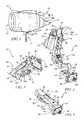
- FIG. 1is a perspective view of an aircraft engine assembly showing that the engine assembly includes a nacelle or fan cowl surrounding a gas turbine engine supported on an aircraft by an engine-mounting bracket and suggesting that the fan cowl incorporates a latch mechanism in accordance with the present disclosure having a flag to indicate to an operator when the latch mechanism is in an unlocked state;
- FIG. 2is a perspective view of the latch mechanism of FIG. 1 showing the latch mechanism in an unlocked and open state and suggesting that a hook member is spaced apart from a clevis to allow panels of the fan cowl to be moved from a closed position to an open position;
- FIG. 3is a lower perspective view of the latch mechanism of FIG. 2 showing the latch mechanism in a locked and closed state and suggesting that a clevis-sensing lock extends through the clevis and engages with flats on an underside of the clevis;
- FIG. 4is an upper perspective view of the latch mechanism of FIG. 3 showing the latch mechanism in the locked and closed state and suggesting that the clevis-sensing lock retains the latch mechanism in the locked and closed state to prevent inadvertent opening of the latch mechanism;
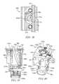
- FIG. 5is an exploded perspective view of the latch mechanism of FIG. 2 showing that the clevis-sensing lock includes a block, a lock cylinder, and an interference member coupled to the lock cylinder and suggesting that a tumbler pin arrangement regulates movement of the lock cylinder;
- FIG. 6is a perspective view of the latch mechanism of FIG. 4 showing a key having the flag attached thereto positioned for insertion into the latch mechanism to engage with the clevis-sensing lock;
- FIG. 7is a view similar to FIG. 6 showing the key inserted into to the clevis-sensing lock and suggesting that the keys is rotated to place the latch mechanism into an unlocked and closed position to allow a user to open the latch mechanism;
- FIG. 8is a lower perspective view of the latch mechanism of FIG. 7 showing that protruding ends of the interference member engages with the flats on a narrowed portion of the clevis prior to rotation of the key;
- FIG. 9is a view similar to FIG. 8 showing the interference member rotated with the key such that flats of the interference member is aligned with the narrowed portion to allow the interference member to pass out through an opening of the clevis;
- FIG. 10is an enlarged perspective view of a hook latch assembly of the latch mechanism of FIG. 2 and showing that the clevis-sensing lock is coupled to an underside surface of a handle of the hook latch assembly;
- FIG. 11is an enlarged view of the clevis-sensing lock of FIG. 10 showing that the lock cylinder extends into the block and a coupler shaft extends through the lock cylinder and interference member to couple the interference member with the lock cylinder to rotate therewith;
- FIG. 12is a perspective view of the latch mechanism of FIG. 6 showing the key partially inserted into the clevis-sensing lock;
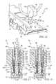
- FIG. 13is a partial sectional view taken along line 13 - 13 in FIG. 12 showing the key extending into the clevis-sensing lock toward the tumbler pin arrangement and suggesting that the tumbler pin arrangement blocks rotation of the lock cylinder when misaligned from a bottom plane of the lock cylinder;
- FIG. 14is a view similar to FIG. 13 showing the key fully inserted into the lock cylinder such that a protrusion of the key engages a shoulder of the lock cylinder such that the tumbler pin arrangement is aligned with the bottom plane of the lock cylinder;
- FIG. 15is a perspective view of the hook latch assembly of FIG. 14 showing the key rotated relative to the handle;
- FIG. 16is a top plan view of the handle of FIG. 15 showing that the protrusion of the key is positioned under the handle to trap the key in the locking mechanism, and suggesting that the key can only be removed when rotated to align with a key hole of the handle;
- FIG. 17is a perspective view of the block of FIG. 15 showing a fastener extending through the block for connecting the block to the handle and suggesting that the fastener rides in a groove of the lock cylinder;
- FIG. 18is a partial sectional view taken along line 18 - 18 in FIG. 17 showing that the fastener engages with the lock cylinder to prevent over-rotation of the lock cylinder;
- FIG. 19is a perspective view of the lock cylinder of FIG. 15 showing that cross-pins slide in a groove of the lock cylinder and are retained by heads of guide pins and suggesting that the lock cylinder is about to rotate relative to the cross-pins;
- FIG. 20is a view similar to FIG. 19 showing the cross-pins located above slots formed in the lock cylinder after rotation of the lock cylinder and suggesting that springs are positioned to force the cross-pins downward;
- FIG. 21is a view similar to FIG. 20 showing the cross-pins positioned in the slots of the lock cylinder and suggesting that the cross-pins prevent rotation of the cylinder while located in the slots;
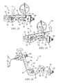
- FIG. 22is a side elevation view of the latch mechanism of FIG. 7 showing the key inserted into the clevis-sensing lock and suggesting that a handle release is rotated to allow the handle to be lifted relative to the clevis;
- FIG. 23is a view similar to FIG. 22 showing the handle partially lifted to pass the clevis-sensing lock out of the clevis;
- FIG. 24is a view similar to FIG. 23 showing the handle rotated relative to the clevis it release the hook member from the clevis;
- FIG. 25is a side elevation view of the latch mechanism of FIG. 7 showing the clevis rotated such that fins coupled to an upper surface are pointing downward and suggesting that the key cannot be rotated or removed while the clevis is in this position;
- FIG. 26is an enlarged view of the latch mechanism of FIG. 25 showing the clevis rotated such that the fins point upwards and suggesting that as the handle is lowered toward the clevis the fins engage with the heads of the guide pins;
- FIG. 27is a view similar to FIG. 26 showing the handle fully lowered and suggesting that the fins of the clevis force the cross-pins upward out of the slot of the lock cylinder to allow rotation and removal of the key;
- FIG. 28is a perspective view of a hook latch assembly incorporating an alternate embodiment of a clevis-sensing lock in accordance with the present disclosure
- FIG. 29is an upper perspective view of the hook latch assembly of FIG. 28 ;
- FIG. 30is an exploded assembly view of the hook latch assembly of FIG. 28 ;
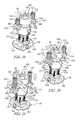
- FIG. 31is a perspective view of the alternative clevis-sensing lock of FIG. 28 ;
- FIG. 32is a perspective view of the alternative clevis-sensing lock of FIG. 31 ;
- FIG. 33is a view similar to FIG. 32 ;
- FIG. 34is a sectional view taken along line 34 - 34 in FIG. 32 ;
- FIG. 35is a view similar to FIG. 34 ;
- FIG. 35is a perspective view of a key used with the alternative clevis-sensing lock of FIG. 31 ;
- FIG. 37is a perspective view of a key interface of the alternative clevis-sensing lock of FIG. 31 ;
- FIG. 38is a sectional view taken along line 38 - 38 in FIG. 35 ;
- FIG. 39is a view similar to FIG. 34 ;
- FIG. 40is an upper perspective view of the alternative clevis-sensing lock of FIG. 31 .
- Engine assembly 10for attachment with an aircraft is shown in FIG. 1 .
- Engine assembly 10includes a nacelle or fan cowl 12 positioned to surround a gas turbine engine 14 supported by an engine-mounting bracket 16 for securing engine assembly 10 to the aircraft.
- Nacelle 12includes a right-side panel 13 and a left-side panel 15 which are movable relative to engine 14 between a closed position, shown in FIG. 1 , and an open position extending away from engine 14 .
- a latch mechanism 30is coupled between panels 13 , 15 to secure panels 13 , 15 in the closed position at the selection of a user as suggested in FIG. 1 .
- the latch mechanismcan be mislocked.
- the latch mechanismcan be closed under some circumstances and appear to be locked to the maintenance professional, when, in fact, it may not be fully engaged or fully locked. It is important to return the aircraft components, such as panels, doors, and cowlings, to the appropriate in-flight condition to seal and house the portions of the aircraft. It is also important to maintain the latch mechanism to retain these components in the closed locked condition. As such, it is important to provide a system to assure that the latch mechanism is, in fact, in the appropriate condition when locked.
- latch mechanism 30includes a hook-handle assembly 32 coupled to one of panels 13 , 15 and a clevis 34 coupled to the other of panels 13 , 15 as suggested in FIG. 2 .
- a clevis-sensing lock 50 in accordance with the present disclosureis coupled to hook-handle assembly 32 and is configured to pass through and engage with clevis 34 to maintain latch mechanism 30 in a locked and closed position as suggested in FIGS. 3 and 4 . It should be noted, that clevis-sensing lock 50 can be configured for use with a variety of latch mechanisms.
- a key 80is inserted into clevis-sensing lock 50 to unlock latch mechanism 30 as suggested in FIGS. 2 and 6-9 .
- a signal flag 17is coupled to key 80 to indicate to an operator or user that latch mechanism 30 is unlocked as suggested in FIGS. 1 and 2 .
- An enlarged head 84 of key 80also provides such an indication if signal flag 17 is lost or removed inadvertently.
- Signal flag 17 and key 80allow a user to inspect engine assembly 10 to ensure that latch mechanisms 30 are locked and closed to secure panels 13 , 15 in the closed position. For example, if no signal flag 17 or key 80 are visible, then there is an indication that latch mechanisms 30 are in the locked and closed position as suggested in FIG. 4 .
- Hook-handle assembly 32includes a handle 42 used to operate latch mechanism 30 , a hook member 40 , and a linkage arrangement 44 coupled between handle 42 and hook member 40 as suggested in FIGS. 2 and 5 .
- Latch mechanism 30is coupled to one of panels 13 , 15 by inserting a pin through a sleeve 36 of linkage arrangement 44 .
- Hook-handle assembly 32moves relative to the pin inserted through sleeve 36 between the unlocked and open position, shown in FIG. 2 , and the locked and closed position, shown in FIG. 4 , and as suggested in FIGS. 22-24 .
- Clevis 34includes a hook-end receiver 62 for engaging with a hook end 60 of hook member 40 and a coupler portion 140 coupled to a clevis retainer 38 as suggested in FIG. 2 .
- coupler portion 140is threaded.
- Clevis retainer 38couples with the other of panels 13 , 15 opposite hook-handle assembly 32 and is configured to allow axial adjustment of clevis 34 by engaging with coupler portion 140 .
- Handle 42is rotated toward clevis 34 to engage hook end 60 with hook-end receiver 62 and pass an interference member 56 of clevis-sensing lock 50 through an opening 52 of clevis 34 , and interference member 56 is rotated by key 80 to engage with flats 106 on an underside 58 of clevis 34 to secure panels 13 , 15 in the closed position so that key 80 can be removed as suggested in FIGS. 2-4 .
- Clevis 34also includes fins 72 positioned on an upper surface 74 to engage with clevis-sensing lock 50 to allow rotation and removal of key 80 as suggested in FIGS. 25-27 .
- Clevis-sensing lock 50includes a block 64 coupled to an underside surface 116 of handle 42 and a coupler shaft 68 configured to couple interference member 56 with block 64 as suggested in FIGS. 2 and 10-11 .
- Block 64is coupled to handle 42 by pins 70 and is configured to receive a tumbler assembly 66 to control rotation of interference member 56 as suggested in FIG. 5 .
- pins 70are in the form of a removable fastener or in the form of a rivet-type fastener.
- a lock cylinder 102 of tumbler assembly 66is received in a bore 154 of block 64 and coupled to coupler shaft 68 to rotate with interference member 56 as suggested in FIG. 5 .
- a tumbler pin arrangement 120 of tumbler assembly 66is positioned between lock cylinder 102 and block 64 to control movement of lock cylinder 102 as suggested in FIGS. 5 and 12-14 .
- Lock cylinder 102is formed to include a bore 92 configured to receive a shaft 98 of key 80 for rotation of lock cylinder 102 and interference member 56 as suggested in FIGS. 5 and 15-18 .
- Tumbler pin arrangement 120includes detent pins 130 , detent springs 132 , and discrete length tumbler pins 122 .
- detent springs 132In the illustrative embodiment, four of each of detent springs 132 , detent pins 130 , and tumbler pins 122 are shown. In some embodiments, more or less of each of detent springs 132 , detent pins 130 , and tumbler pins 122 are used.
- the unique arrangement of tumbler pins 122 between various latch mechanisms 30provides a degree of selectivity to allow only certain keys 80 to work with each clevis-sensing lock 50 , thus providing a general security keying feature. While a uniform key could be used across all latching platforms, the additional security may enhance the use of the clevis-sensing lock 50 to provide security features as well as the above described and herein described benefits.
- Tumbler pins 122are inserted into corresponding bores within lock cylinder 102 and lock cylinder 102 is inserted into bore 154 of block 64 as suggested in FIG. 5 .
- Detent pins 130are inserted into block 64 to engage with tumbler pins 122 and detent springs 132 are inserted into block 64 to engage with detent pins 130 .
- a retainer plate 134is engaged with an underside of block 64 to retain tumbler pin arrangement 120 within block 64 .
- Coupler shaft 68is inserted though interference member 56 and is coupled to coupler shaft 68 by a pin 104 extending through holes 107 , 109 of interference member 56 and coupler shaft 68 , respectively.
- Guide pins 110are received in cavities 76 of block 64 as suggested in FIG. 5 .
- Guide pins 110include a head 182 and shaft 111 coupled to head 182 .
- a spring 112is positioned to surround shaft 111 .
- Head 182is formed to include a hole 190 for receiving a cross-pin 114 .
- Guide pins 110 and springs 112are inserted into cavities 76 and cross-pins 114 are inserted through slots 192 formed in block 64 and holes 190 of heads 182 to retain guide pins 110 within cavities 76 .
- Block 64is coupled to handle 42 by pins 70 such that an upper portion of cavities 76 and side portions of slots 192 are covered. As such, handle 42 retains springs 112 within cavities 76 and cross-pins 114 within slots 192 .
- Interference member 56includes protruding portions 150 and flats 142 extending between protruding portions 150 as shown in FIG. 8 .
- Protruding portions 150are configured to engage with flats 106 of a narrowed portion 146 of clevis 34 to lock latch mechanism 30 .
- Key 80is inserted through an aperture 82 in handle 42 to engage with clevis-sensing lock 50 as suggested in FIG. 6 .
- Key 80is then rotated to rotate interference member 56 and align flats 142 with narrowed portion 146 such that protruding portions 150 are disengaged from flats 106 and interference member 56 is allowed to pass through opening 52 of clevis 34 as suggested in FIGS. 7-9 .
- Clevis-sensing lock 50as assembled, is shown in FIGS. 10 and 11 .
- Coupler shaft 68 and lock cylinder 102are aligned with aperture 82 of handle 42 to allow insertion of key 80 as suggested in FIG. 10 .
- Detent pins 130are positioned to engage with lock cylinder 102 to block rotation of lock cylinder 102 until key 80 is inserted as suggested in FIG. 11 .
- clevis-sensing lock 50was assembled and attached to handle 42 such that clevis-sensing lock 50 is initially in the locked orientation as suggested in FIGS. 10 and 11 . After key 80 is inserted and turned for the first time, clevis-sensing lock 50 will need to be engaged with clevis 34 in order to turn and remove key 80 as further detailed below.
- Key 80includes head 84 and shaft 98 coupled to head 84 as shown in FIG. 5 .
- Shaft 98is hollow to define a cavity 96 sized to receive coupler shaft 68 .
- Lock cylinder 102is formed to define a shoulder 101 as shown in FIG. 17 .
- a protrusion 94extends radially from shaft 98 and aperture 82 of handle 42 is shaped to allow shaft 98 and protrusion 94 to pass therethrough as suggested in FIG. 12 .
- an interface between tumbler pins 122 and detent pins 130is misaligned from a bottom plane P of lock cylinder 102 such that detent pins 30 engage with lock cylinder 102 and block 64 to prevent rotation of lock cylinder 102 as suggested in FIG. 13 .
- a leading end 90 of key 80having mating portions 124 corresponding to tumbler pins 122 , extends into lock cylinder 102 to engage with tumbler pins 122 and align detent pins 130 with bottom plane P to allow rotation of lock cylinder 102 as suggested in FIGS. 13 and 14 .
- Protrusion 94 of key 80engages with shoulder 101 of lock cylinder 102 to limit insertion of key 80 and ensure proper alignment of detent pins 130 with bottom plane P.
- protrusion 94extends under handle 42 and becomes misaligned from aperture 82 as suggested in FIGS. 15 and 16 .
- key 80is trapped inside clevis-sensing lock 50 until key 80 is turned to re-lock clevis-sensing lock 50 . This prevents key 80 and signal flag 17 from being removed before latch mechanism 30 is in the locked and closed position to ensure that panels 13 , 15 are properly secured in the closed position.
- Lock cylinder 102is formed to include a groove 170 as shown in FIGS. 17 and 18 .
- One of pins 70extends through block 64 to engage with groove 170 .
- Groove 170only partially extends around lock cylinder 102 to control rotation of lock cylinder 102 .
- lock cylinder 102is limited to about 90 degrees of rotation. In some embodiments, that lock cylinder 102 rotates further than 90 degrees.
- Lock cylinder 102is also formed to include an annular groove 158 with axial slots 180 extending downward therefrom as shown in FIGS. 19-21 . Cross-pins 114 slide in annular groove 158 as lock cylinder 102 is rotated as suggested in FIGS. 19-20 .
- Lock cylinder 102is rotated until cross-pins 114 are aligned with axial slots 180 .
- Cross-pins 114are forced into axial slots 180 by springs 112 to engage with lock cylinder 102 and block rotation of lock cylinder 102 as suggested in FIGS. 20-21 .
- latch mechanism 30can be opened as suggested in FIGS. 22-24 .
- a handle release 46is coupled to handle 42 and engages with hook member 40 when latch mechanism 30 is in a closed position as suggested in FIG. 22 .
- Handle release 46is rotated to disengage from hook member 40 .
- Handle 42is lifted to pass interference member 56 out of clevis 34 as suggested in FIG. 23 . Further rotation of handle 42 disengages hook end 60 from hook-end receiver 62 to allow movement of hook-handle assembly 32 relative to clevis 34 as suggested in FIG. 24 .
- Fins 72 of clevis 34are engage with guide pins 110 to allow rotation and removal of key 80 as suggested in FIGS. 25-27 .
- Clevis 34is shown with fins 72 facing downward in FIG. 25 .
- latch mechanism 30is prevented from being in an improper unlocked and closed position where panels 13 , 15 may inadvertently open during operation of the aircraft.
- fins 72engage with guide pins 110 during closure of latch mechanism 30 to move cross-pins 114 out of axial slots 180 and allow rotation of lock cylinder 102 as suggested in FIGS. 26-27 .
- FIG. 28A hook-handle assembly 32 a incorporating an alternative clevis-sensing lock 50 a in accordance with the present disclosure is shown in FIG. 28 . Similar to hook-handle assembly 32 , hook-handle assembly 32 a includes a handle 42 a , a hook member 40 a , and a linkage arrangement 44 a coupled between handle 42 a and hook member 40 a . A handle release 46 a is coupled to handle 42 a to engage with hook member 40 a . Clevis-sensing lock 50 a is coupled to an underside surface 116 a of handle 42 a .
- hook-handle assembly 32 a and clevis-sensing lock 50 aare configured to cooperate with the same clevis 34 as hook-handle assembly 32 of latch mechanism 30 , described above.
- Hook-handle assembly 32 aalso operates in a similar fashion to hook-handle assembly 32 .
- discussion of hook-handle assembly 32 awill be limited for sake of brevity.
- features of hook-handle assembly 32can be incorporated into hook-handle assembly 32 a , and vice versa, without departing from the present disclosure.
- Clevis-sensing lock 50 aincludes a block 64 a and a lock cylinder 102 a configured to couple an interference member 56 a with block 64 a as suggested in FIGS. 28 and 30 .
- Block 64 ais coupled to handle 42 a by pins 70 a and is configured to receive a key interface 68 a to control rotation of interference member 56 a coupled to lock cylinder 102 a as suggested in FIG. 30 .
- Lock cylinder 102 ais received in a bore 154 a of block 64 a and coupled to key interface 68 a by a pin assembly 104 a to rotate with interference member 56 a .
- Pin assembly 104 amoves relative to a notch 184 a of block 64 a to control movement of lock cylinder 102 a as suggested in FIGS. 32-35 .
- Lock cylinder 102 ais formed to include a bore 92 a aligned with an aperture 82 a of handle 42 a and configured to receive a shaft 98 a of a key 80 a for rotation of lock cylinder 102 a and interference member 56 a as suggested in FIGS. 29 and 30 .
- Key 80 aincludes a head 84 a coupled to shaft 98 a .
- Shaft 98 ais formed to define a flat side 97 a to orient key 80 a during insertion.
- Key 80 aalso includes a grip tip 91 a coupled to shaft 98 a and configured to engage with key interface 68 a as suggested in FIGS. 30 and 36-37 .
- a tamper guard 186 aTo assemble clevis-sensing lock 50 a , a tamper guard 186 a , key interface 68 a , a spring 136 a , and a spacer 188 a are inserted into lock cylinder 102 a and retained therein by a retainer ring 189 a as suggested in FIG. 30 .
- a pin 113 ais inserted through a slot 107 a of lock cylinder 102 a and a hole 109 a of key interface 68 a .
- Pin 113 ais secured by a sleeve 115 a coupled to pin 113 a to form pin assembly 104 a .
- Spring 136 aengages with spacer 188 a to bias key interface 68 a and pin assembly 104 a toward an upper end of slot 107 a.
- Guide pins 110 aare received in cavities 76 a of block 64 a as suggested in FIG. 30 .
- Guide pins 110 ainclude a head 182 a and shaft 111 a coupled to head 182 a .
- a spring 112 ais positioned to surround shaft 111 a .
- Head 182 ais formed to include a hole 190 a for receiving a cross-pin 114 a .
- Guide pins 110 a and springs 112 aare inserted into cavities 76 a and cross-pins 114 a are inserted through slots 192 a formed in block 64 a and holes 190 a of heads 182 a to retain guide pins 110 a within cavities 76 a .
- Lock cylinder 102 ais inserted into a bore 154 a of block 64 a and engaged by cross-pins 114 a.
- a ball detent assembly 172 ais positioned within a ball detent receiver 178 a as suggested in FIG. 30 .
- Ball detent assembly 172 aincludes a spring 174 a and a ball bearing 176 a .
- Spring 174 ais configured to bias ball bearing 176 a toward a detent recess 179 a of lock cylinder 102 a as suggested in FIG. 40 .
- Block 64 ais coupled to handle 42 a by pins 70 a such that an upper portion of cavities 76 a and ball detent receiver 178 a , and side portions of slots 192 a , are covered as suggested in FIG. 30 .
- handle 42 aretains springs 112 a within cavities 76 a , ball detent assembly 172 a within ball detent receiver 178 a , and cross-pins 114 a within slots 192 a.
- interference member 56 aincludes protruding portions 150 a and flats 142 a extending between protruding portions 150 a as shown in FIG. 30 .
- Protruding portions 150 aare configured to engage with clevis 34 .
- Flats 142 aare configured to align with clevis 34 such that protruding portions 150 a are disengaged from clevis 34 and interference member 56 a is allowed to pass through opening 52 of clevis 34 .
- Clevis-sensing lock 50 ais shown in FIG. 31 .
- clevis-sensing lock 50 awas assembled and attached to handle 42 a such that clevis-sensing lock 50 a is initially in a locked orientation.
- clevis-sensing lock 50will need to be engaged with clevis 34 in order to turn and remove key 80 a as further detailed below.
- Key 80 ais inserted into clevis-sensing lock 50 a to move pin assembly 104 a out of notch 184 a as suggested in FIGS. 32 and 33 .
- Shaft 98 a of key 80 aextends into lock cylinder 102 a and grip tip 91 a passes through tamper guard 186 a to engage with key interface 68 a as suggested in FIG. 34 .
- Key 80 ais forced downward against the force of spring 136 a to move pin assembly 104 a as suggested in FIG. 35 .
- grip tip 91 ahas a geometric shape, such as a triangle, which corresponds with a geometric shape of a tip receiver 69 a of key interface 68 a as suggested in FIGS.
- Key interface 68 aalso includes a projecting portion 67 a to engage with lock cylinder 102 a .
- grip tip 91 aengages with tip receiver 69 a to rotate key interface 68 a , which in turn engages with lock cylinder 102 a to rotate lock cylinder 102 a with key 80 a.
- Shaft 98 a of key 80 ais formed to include a groove 95 a as suggested in FIGS. 35-36 and 38 .
- Side 97 a of shaft 98 aallows key 80 a to pass by pin 70 and into lock cylinder 102 a as suggested in FIG. 35 .
- Key 80 ais allowed to turn to unlock clevis-sensing lock 50 a when groove 95 a aligns with pin 70 a as suggested in FIGS. 35 and 38 .
- Lock cylinder 102 aalso includes a groove 170 a which cooperates with pin 70 a to restrict rotation of lock cylinder 102 a .
- Cross-pins 114 acooperate with a groove 158 a and slot 180 a of lock cylinder 102 a to further control rotation of lock cylinder 102 a , as suggested in FIGS. 30 and 31 , similar to clevis-sensing lock 50 , described above.
- Clevis-sensing lock 50 aincludes anti-tamper features as suggested in FIGS. 39 and 40 .
- Tamper guard 186 aminimizes the ability of a lock pick 99 a , such as a screw driver or other tool, to enter clevis-sensing lock 50 a and rotate lock cylinder 102 a as suggested in FIG. 39 .
- Tamper guard 186 ais configured to slide and rotate on key interface 68 a without providing sufficient friction to turn lock cylinder 102 a to disengage interference member 56 a from clevis 34 .
- Ball detent assembly 172 aengages with lock cylinder 102 a to increase the force required to turn lock cylinder 102 a as suggested in FIG. 40 . These features cooperate to prevent unlocking of clevis-sensing lock 50 a without the use of key 80 a.
- the clevis-sensing locks described hereincan be configured for use with a specific latch design or configured to be used as a retrofit on a remanufactured latch.
- An existing latch assemblycan reuse most of the parts with perhaps a modification to the handle to remove a pre-existing handle release and to accommodate a clevis-sensing lock.
- the cleviscan be replaced merely by disengaging the threaded portion of the old clevis and attaching a new clevis which will include the fins and other corresponding structures detailed above. This design is easy to operate, difficult to defeat, and provides a nearly fail-proof method of ensuring the latch has properly secured the latch cowl.
- a clevis-sensing lockcan be retained on a latch mechanism for preventing the latch mechanism from opening inadvertently.
- the clevis-sensing lockincludes a tool, key, or other device which must be used to unlock the clevis-sensing lock to permit movement of the handle to disengage the latch mechanism.
- the keycannot be removed from the lock when the latch is open.
- the keyincludes a visual indicator such as a flag, streamer, or other device which provides a clear visual indicator that the key is retained in the lock. This visual indicator extends away from the aircraft to provide a clear visual indication of the unlatched condition. Since the key can only be removed from the lock when the latch is, in fact, in a proper closed position, the presence of such a visual indicator indicates that the latches are not secure for flight operations.
- Engine cowlsmay sometimes appear to be in a latched closed position when they are not due to the low profile of the latches and low height from the ground of the engines of the aircraft. It is often times that technicians will clip the latches up tight against the cowling without latching them to prevent snags with clothing during operations on the engine. These situations can be problematic if an aircraft takes off while the latches are open, and may cause damage to the cowlings or engines while in flight.
- a clevis sensing lockcan be attached to any hook latch that engages with a clevis.
- the clevis sensing lockattaches to the handle of the hook latch, and passes through the clevis when the latch is closed. It requires a key or tool to unlock the latch and allow the latch to open.
- the keycannot be removed from the handle. They key has a long flag or streamer attached to it so that anybody standing around the aircraft, not necessarily near the engine, can see that the cowls are not closed and latched.
- the operatorinserts the key, with the long flag or streamer attached, into the latch, turns the key, then opens the latch.
- the lockincludes a block which holds all of the lock's internal parts to the handle of the hook latch.
- the blockhas a large hole for a lock cylinder, and some slots and holes for some pins, guides, and springs. Another pair of slots on the block allows fins that are attached to the clevis to fit into the block.
- the T-shaped lock cylinderwhich fits into the block, has two large flats on one end, which allows it to fit through the clevis during handle opening and closing.
- the lock cylinderhas a retaining groove that protrudes into the hole, but only part way around the lock cylinder.
- This groove on the lock cylinderengages with a rivet that passes through the handle and through the block in such a way that the lock cylinder cannot come out of the lock, and in such a way that the lock cylinder can only turn a predetermined amount.
- the rivetprotrudes into the hole of the lock such that the key has a corresponding flat on it that allows the key to pass by the rivet when the latch is closed.
- a groove on the keymatches the groove on the lock cylinder that engages with the rivet that holds the lock cylinder in place.
- the groove on the keyengages with the rivet, which prevents the key from being removed.
- the end of the keyhas a feature which grabs onto a mating component, sometimes called a plug, down in the bottom of the hole of the lock cylinder.
- the shape at the end of the keycan be any shape that allows the key to grab the plug and turn it.
- the plughas a spring behind it, and a hole for a cross pin, which fits into a through slot on the lock cylinder.
- the cross pinlimits the amount of axial movement in the lock cylinder and also ensures that the key, plug, and lock cylinder turn together.
- the cross pinis pushed by the spring, via the plug, into a V-groove on the block, thereby preventing accidental rotation of the lock cylinder when the latch is closed.
- the lock cylinderalso has a circular groove and two intersecting straight slots, which are parallel to the axis of the lock cylinder, that allow the ends of two locking pins to travel in them.
- the locking pinsride in a guide, inside the block.
- Each guideis pushed by a spring toward the clevis.
- the clevishas two fins which, in the latch closed position, engage with the guides, and push the guides and locking pins into the circular groove.
- the lockmay be turned toward the unlock position. Once the lock cylinder is turned completely to the unlock position, the handle may be moved in the direction that opens the latch, and the engaging portion of the lock may pass through the clevis.
- the clevishas two fins which fit into some blind slots on the block, and push the guides and locking pins when the latch is closed. As the latch opens, and the handle moves away from the clevis, the fins on the clevis disengage from the guides and locking pins. The locking pins are then pushed down into the straight slots on the lock cylinder, which prevents the lock cylinder from turning toward the lock position and prevents the key from being removed.
- the locking pinswould be longer and offset from the axis of the cylinder, such that they would fit tangentially into the circular groove on lock cylinder when the latch is in the closed position. When the latch is open, the locking pins would slide down onto the flats of the lock cylinder and prevent the lock cylinder from turning.
Landscapes
- Engineering & Computer Science (AREA)
- Structural Engineering (AREA)
- Mechanical Engineering (AREA)
- Lock And Its Accessories (AREA)
Abstract
Description
Claims (13)
Priority Applications (3)
| Application Number | Priority Date | Filing Date | Title |
|---|---|---|---|
| US15/510,139US10392830B2 (en) | 2014-09-09 | 2015-09-09 | Clevis sensing lock |
| US29/848,441USD973463S1 (en) | 2014-09-09 | 2022-08-02 | Aircraft latch lock key head |
| US29/863,825USD1088806S1 (en) | 2014-09-09 | 2022-12-22 | Aircraft latch lock key |
Applications Claiming Priority (3)
| Application Number | Priority Date | Filing Date | Title |
|---|---|---|---|
| US201462048247P | 2014-09-09 | 2014-09-09 | |
| US15/510,139US10392830B2 (en) | 2014-09-09 | 2015-09-09 | Clevis sensing lock |
| PCT/US2015/049216WO2016040501A1 (en) | 2014-09-09 | 2015-09-09 | Clevis sensing lock |
Related Parent Applications (1)
| Application Number | Title | Priority Date | Filing Date |
|---|---|---|---|
| PCT/US2015/049216A-371-Of-InternationalWO2016040501A1 (en) | 2014-09-09 | 2015-09-09 | Clevis sensing lock |
Related Child Applications (1)
| Application Number | Title | Priority Date | Filing Date |
|---|---|---|---|
| US16/393,646DivisionUS11193305B2 (en) | 2014-09-09 | 2019-04-24 | Lock apparatus |
Publications (2)
| Publication Number | Publication Date |
|---|---|
| US20170306669A1 US20170306669A1 (en) | 2017-10-26 |
| US10392830B2true US10392830B2 (en) | 2019-08-27 |
Family
ID=55459524
Family Applications (5)
| Application Number | Title | Priority Date | Filing Date |
|---|---|---|---|
| US15/510,139Active2035-11-25US10392830B2 (en) | 2014-09-09 | 2015-09-09 | Clevis sensing lock |
| US16/393,646Active2036-11-02US11193305B2 (en) | 2014-09-09 | 2019-04-24 | Lock apparatus |
| US17/326,120ActiveUS11773622B2 (en) | 2014-09-09 | 2021-05-20 | Key, lock, and latch assembly |
| US29/848,441ActiveUSD973463S1 (en) | 2014-09-09 | 2022-08-02 | Aircraft latch lock key head |
| US29/863,825ActiveUSD1088806S1 (en) | 2014-09-09 | 2022-12-22 | Aircraft latch lock key |
Family Applications After (4)
| Application Number | Title | Priority Date | Filing Date |
|---|---|---|---|
| US16/393,646Active2036-11-02US11193305B2 (en) | 2014-09-09 | 2019-04-24 | Lock apparatus |
| US17/326,120ActiveUS11773622B2 (en) | 2014-09-09 | 2021-05-20 | Key, lock, and latch assembly |
| US29/848,441ActiveUSD973463S1 (en) | 2014-09-09 | 2022-08-02 | Aircraft latch lock key head |
| US29/863,825ActiveUSD1088806S1 (en) | 2014-09-09 | 2022-12-22 | Aircraft latch lock key |
Country Status (5)
| Country | Link |
|---|---|
| US (5) | US10392830B2 (en) |
| EP (2) | EP3191666B1 (en) |
| CA (1) | CA2960880C (en) |
| ES (2) | ES2760538T3 (en) |
| WO (1) | WO2016040501A1 (en) |
Cited By (7)
| Publication number | Priority date | Publication date | Assignee | Title |
|---|---|---|---|---|
| US11035155B2 (en)* | 2018-10-17 | 2021-06-15 | Roy L. Fox, Jr. | Lever-lock release systems and methods |
| US20210270057A1 (en)* | 2014-09-09 | 2021-09-02 | Hartwell Corporation | Key, lock, and latch assembly |
| USD930455S1 (en)* | 2019-10-10 | 2021-09-14 | S.P.E.P. Acquisition Corp. | Dual holes for a trigger to attach a padlock |
| US11330728B2 (en)* | 2019-11-19 | 2022-05-10 | Pegatron Corporation | Handle extension structure and electronic device casing |
| US20230250682A1 (en)* | 2014-03-13 | 2023-08-10 | Qrp, Inc. | Hook Latch With Adjustable Throw |
| WO2024079423A1 (en)* | 2022-10-13 | 2024-04-18 | Safran Nacelles | Lock system for turbine engine nacelle and nacelle including same |
| US20240425244A1 (en)* | 2023-06-20 | 2024-12-26 | A&A Intelligent (Shenzhen) Co., Ltd. | Lock catch structure and storage box of chess pieces |
Families Citing this family (7)
| Publication number | Priority date | Publication date | Assignee | Title |
|---|---|---|---|---|
| CN108166849B (en)* | 2017-12-21 | 2019-08-02 | 中航沈飞民用飞机有限责任公司 | A kind of passenger plane hatch door latch joint driving visual indicating device |
| US11866189B2 (en)* | 2020-03-26 | 2024-01-09 | Hartwell Corporation | Latching system with movable anti-shear mechanism |
| US20220267018A1 (en)* | 2021-02-20 | 2022-08-25 | Andres Hernandez | High visibility hook latch |
| US12012790B2 (en) | 2022-09-02 | 2024-06-18 | Rohr, Inc. | Latch assembly |
| USD1093119S1 (en)* | 2022-10-14 | 2025-09-16 | Dormakaba Schweiz Ag | Key |
| EP4368513A1 (en)* | 2022-11-10 | 2024-05-15 | Rohr, Inc. | Aircraft latch assembly with lock |
| US12371180B2 (en) | 2023-04-03 | 2025-07-29 | Rohr, Inc. | Long throw latch for aircraft system |
Citations (73)
| Publication number | Priority date | Publication date | Assignee | Title |
|---|---|---|---|---|
| US2592647A (en) | 1945-06-08 | 1952-04-15 | Trailmobile Inc | Locking mechanism for vehicle doors |
| US2601577A (en) | 1947-09-29 | 1952-06-24 | Motor Products Corp | Latch and handle mechanism |
| US2710214A (en) | 1952-12-31 | 1955-06-07 | Camloc Fastener Corp | Latch fastener |
| US2722445A (en) | 1952-08-15 | 1955-11-01 | Clark Hartwell | Flush latch construction |
| US2904141A (en)* | 1957-04-22 | 1959-09-15 | Clark Hartwell | Adjustable hook latch |
| US3070395A (en) | 1960-09-13 | 1962-12-25 | Boeing Co | Latch mechanism |
| US3194595A (en) | 1962-08-21 | 1965-07-13 | Camloc Fastener Corp | Safety device for cowling latch |
| US3209563A (en) | 1962-11-06 | 1965-10-05 | Eastern Co | Door control mechanism |
| US3279836A (en) | 1964-02-24 | 1966-10-18 | Emhart Corp | Dead latch construction |
| US3958821A (en) | 1974-02-25 | 1976-05-25 | Rowe International Inc. | Door operating assembly for merchandising machine or the like |
| US4053177A (en)* | 1976-06-08 | 1977-10-11 | Tridair Industries | Adjustable latch |
| US4069696A (en) | 1976-08-20 | 1978-01-24 | Chicago Lock Co. | Axial split-pin tumbler-type lock and key therefor |
| US4116479A (en)* | 1977-01-17 | 1978-09-26 | Hartwell Corporation | Adjustable flush mounted hook latch |
| US4134281A (en) | 1977-08-08 | 1979-01-16 | The Eastern Company | Cam-type door lock with recessed handle |
| US4191036A (en) | 1978-01-16 | 1980-03-04 | Chicago Lock Co. | Axial split-pin tumbler-type lock mechanism and key therefor |
| US4268077A (en) | 1978-08-28 | 1981-05-19 | Abex Corporation | Self-storing door handle |
| US4307905A (en) | 1979-09-20 | 1981-12-29 | Hartwell Corporation | Toggle latch assembly |
| US4413849A (en) | 1980-02-26 | 1983-11-08 | The Eastern Company | Tool-operated flush-mountable latch |
| US4446709A (en) | 1981-07-14 | 1984-05-08 | Chicago Lock Co. | Cylinder lock mechanism |
| US4510779A (en) | 1982-07-16 | 1985-04-16 | Adams Rite Products, Inc. | Aircraft door lock actuating mechanism |
| US4613099A (en) | 1982-02-05 | 1986-09-23 | The Boeing Company | Latch signal and cowling structure |
| US4638649A (en) | 1985-05-07 | 1987-01-27 | Echolac Co., Ltd. | Dual action luggage latch |
| US4735069A (en) | 1982-03-23 | 1988-04-05 | Chicago Lock Co. | Cylinder lock and key |
| US4736174A (en) | 1987-04-23 | 1988-04-05 | General Electric Company | Molded case circuit breaker operating mechanism |
| US4743052A (en) | 1986-01-24 | 1988-05-10 | Rexnord Inc. | Tension latch assembly |
| US4911485A (en) | 1989-01-30 | 1990-03-27 | The Hartwell Corporation | Latch structure |
| US4925221A (en) | 1988-09-01 | 1990-05-15 | Vsi Corp. | Toggle latch with automatic safety catch |
| US4934164A (en) | 1989-06-12 | 1990-06-19 | Shew Ming Chwan | Cylinder lock |
| US5201557A (en) | 1991-09-24 | 1993-04-13 | Southco, Inc. | Slide fastener |
| US5257839A (en) | 1991-06-10 | 1993-11-02 | National Manufacturing Co. | Tension latch assembly |
| US5267762A (en)* | 1992-02-20 | 1993-12-07 | Southco, Inc. | Latch with connecting parts forming a seal |
| US5321962A (en) | 1991-08-29 | 1994-06-21 | Ferchau Joerg U | Injector/ejector latch lock mechanism |
| US5454239A (en) | 1993-03-05 | 1995-10-03 | Takigen Manufacturing Co. Ltd. | Door locking handle assembly of pull-out and side-swinging lever-action type |
| US5469725A (en) | 1993-03-16 | 1995-11-28 | Takigen Manufacturing Co., Ltd. | Door locking handle assembly of pull-out and side-swinging lever-action type |
| US5518206A (en) | 1992-05-22 | 1996-05-21 | Short Brothers Plc | Closure default indicator |
| US5620212A (en)* | 1995-08-28 | 1997-04-15 | Hartwell Corporation | Low profile hook latch assembly |
| US5638709A (en) | 1994-04-25 | 1997-06-17 | Clavin; Timothy J. | Trigger latch |
| US5713482A (en)* | 1996-05-02 | 1998-02-03 | Container Accessories, Inc. | Polymeric split ring clamp |
| US5765883A (en) | 1995-07-14 | 1998-06-16 | Hartwell Corporation | Adjustable pressure relief latch |
| US5984382A (en) | 1998-03-13 | 1999-11-16 | Hartwell Corporation | Extended reach latch |
| US6174007B1 (en) | 1999-05-19 | 2001-01-16 | Southco, Inc. | Actuator assembly |
| US6279971B1 (en) | 1999-10-05 | 2001-08-28 | Hartwell Corporation | Latch with sensor |
| US6325428B1 (en) | 1999-11-10 | 2001-12-04 | Hartwell Corporation | Latch assembly including sensor |
| US6343815B1 (en) | 2000-10-04 | 2002-02-05 | Hartwell Corporation | Cinch-up latch |
| US20020195827A1 (en) | 2001-06-20 | 2002-12-26 | Jackson Frank T. | Blowout latch |
| US6513841B1 (en) | 2000-10-10 | 2003-02-04 | Hartwell Corporation | Blowout latch |
| US20040104583A1 (en) | 2001-11-27 | 2004-06-03 | Alain Porte | Device for indicating incorrect closure of locking means located between two fan cowlings of an aircraft engine nacelle |
| US20040231379A1 (en) | 2003-05-20 | 2004-11-25 | Chin-Shen Yu | Shaft-type locking cylinder and dedicated key |
| US7017955B1 (en)* | 2004-11-03 | 2006-03-28 | Asmith Manufacturing Company | Draw latch having kick-out catch |
| US20060214431A1 (en) | 2005-03-25 | 2006-09-28 | Helsley Thomas J | Latch mechanism |
| US20080129056A1 (en) | 2006-11-30 | 2008-06-05 | Hartwell Corporation | Command Latch and Pin Latch System |
| US7461871B2 (en) | 2003-07-10 | 2008-12-09 | Aircelle | Latch for joining two panels of an airplane structure |
| US7503600B2 (en) | 2003-10-14 | 2009-03-17 | Abloy Oy | Locking arrangement |
| US20090134637A1 (en) | 2007-11-26 | 2009-05-28 | Zarko Baic | Flush latch with positive lock |
| US20110101710A1 (en) | 2008-01-31 | 2011-05-05 | Hartwell Corporation | Tool operated channel latch |
| US8113551B2 (en) | 2007-06-13 | 2012-02-14 | Avibank Manufacturing, Inc. | Radome latch and keeper |
| US8186728B2 (en) | 2009-09-09 | 2012-05-29 | Eduard Kopylov | Draw latch with safety catch |
| US8419088B2 (en) | 2007-12-17 | 2013-04-16 | Avibank Manufacturing, Inc. | Latches and latching systems having a positive status indicator |
| US20130238326A1 (en) | 2012-03-08 | 2013-09-12 | Lg Electronics Inc. | Apparatus and method for multiple device voice control |
| US20140030079A1 (en) | 2011-03-29 | 2014-01-30 | Aircelle | Locking device with mechanical detection of closure and opening |
| US8720237B2 (en) | 2011-10-19 | 2014-05-13 | Daws Manufacturing Company, Inc. | Rotary latch |
| US8764072B2 (en) | 2010-10-21 | 2014-07-01 | Aircelle | Locking device with mechanical detection of closing and opening |
| US20140225380A1 (en) | 2011-08-22 | 2014-08-14 | Aircelle | Locking device with mechanical detection of closing and opening |
| US8864185B2 (en)* | 2010-03-18 | 2014-10-21 | Alcoa Inc. | Latch with adjustable handle |
| US8864189B2 (en)* | 2009-06-22 | 2014-10-21 | Airbus Operations (S.A.S.) | Aircraft latch comprising a hook and a handle |
| US9004548B2 (en) | 2007-05-25 | 2015-04-14 | Aircelle | Device for locking an opening part of a jet engine nacelle with respect to a fixed part, and nacelle equipped with such a device |
| US20150184544A1 (en) | 2014-01-02 | 2015-07-02 | Airbus Operations (Sas) | Fan cowl locking system |
| US20150184543A1 (en) | 2014-01-02 | 2015-07-02 | Airbus Operations (Sas) | Fan cowl locking system |
| WO2015126950A1 (en) | 2014-02-18 | 2015-08-27 | Hartwell Corporation | Tool operated channel latch |
| US9140041B2 (en)* | 2012-06-08 | 2015-09-22 | Weston Body Hardware Limited | Compression latch |
| US9169678B2 (en) | 2009-12-04 | 2015-10-27 | Hartwell Corporation | Pressure relief latch mechanism |
| US9353559B2 (en) | 2014-04-22 | 2016-05-31 | Airbus Operations (Sas) | Latching system for securing two components |
| US9567784B2 (en)* | 2010-10-25 | 2017-02-14 | Lisi Aerospace | Hook latch fitted with a positioning device and a method for assembling such a latch |
Family Cites Families (65)
| Publication number | Priority date | Publication date | Assignee | Title |
|---|---|---|---|---|
| US2677261A (en)* | 1948-01-16 | 1954-05-04 | Briggs & Stratton Corp | Door handle lock |
| US2982121A (en)* | 1958-07-07 | 1961-05-02 | Harry F George | Tumbler lock and key |
| US3261188A (en)* | 1964-07-15 | 1966-07-19 | Chicago Lock Co | Quick-change axial pin tumbler lock assembly |
| US3320783A (en)* | 1966-12-09 | 1967-05-23 | Chicago Lock Co | Key for an axial tumbler type lock |
| US3420077A (en)* | 1966-12-16 | 1969-01-07 | George E Drazin | Pick-proof locks |
| US3509748A (en)* | 1968-04-24 | 1970-05-05 | Fort Lock Corp | Axial pin tumbler lock |
| US3541819A (en)* | 1968-08-05 | 1970-11-24 | Chicago Lock Co | Tamper-proof axial tumbler lock |
| US3797289A (en)* | 1973-01-17 | 1974-03-19 | L Mercurio | Radially arranged tumbler type lock |
| US3961507A (en) | 1975-01-17 | 1976-06-08 | Fork Lock Corporation | Resettable axial pin tumbler lock |
| US4109495A (en)* | 1976-03-26 | 1978-08-29 | Roberts Marvin E | Key and tumbler construction |
| USD246761S (en) | 1976-06-07 | 1977-12-27 | Emhart Industries, Inc. | Key blank |
| US4083211A (en)* | 1977-04-18 | 1978-04-11 | Chicago Lock Co. | Axial split-pin tumbler-type lock mechanism for a handle lock |
| US4111020A (en) | 1977-08-15 | 1978-09-05 | Chicago Lock Co. | Pick-resistant axial split-pin tumbler-type lock mechanism |
| US4233828A (en)* | 1978-11-22 | 1980-11-18 | Keystone Consolidated Industries, Inc. | Changeable combination, axial pin tumbler lock with single interface |
| JPS59217879A (en)* | 1983-05-21 | 1984-12-08 | タキゲン製造株式会社 | Lock apparatus for two-operation-bundle control |
| USD290085S (en) | 1985-05-20 | 1987-06-02 | Best Lock Corporation | Key blank |
| USD301542S (en)* | 1987-04-27 | 1989-06-13 | Smith & Wesson Corp. | Key for handcuffs |
| US5097686A (en) | 1987-12-28 | 1992-03-24 | Consolidated International Automotive, Inc. | Security locking system for vehicle wheel nuts |
| US4977768A (en) | 1988-11-09 | 1990-12-18 | 775 Corporation | Pick-resistant axial split-pin tumbler lock |
| US5018376A (en)* | 1989-03-27 | 1991-05-28 | Lee David G | High security axial pin tumbler lock |
| USD317249S (en)* | 1989-06-13 | 1991-06-04 | Equipment Systems & Devices, Inc. | Key |
| USD328019S (en)* | 1989-08-22 | 1992-07-21 | Beizer Jerald S | Screwdriver |
| US4899565A (en) | 1989-08-30 | 1990-02-13 | Chicago Lock Company | Square shaped axial split pin tumbler lock |
| US5024072A (en) | 1990-08-28 | 1991-06-18 | Miko Lee | Tumbler pin lock system |
| USD332388S (en) | 1991-01-10 | 1993-01-12 | Master Lock Company | Key |
| US5819563A (en) | 1991-10-21 | 1998-10-13 | Bianco; James S. | Intelligent lock system |
| USD343778S (en)* | 1992-03-11 | 1994-02-01 | Helge Brix-Hansen | Lid opener |
| US5400629A (en)* | 1992-06-01 | 1995-03-28 | Fort Lock Corporation | Axial pin tumbler lock |
| JP3150816B2 (en) | 1993-03-24 | 2001-03-26 | 株式会社アルファ | Cylinder lock |
| US5435160A (en)* | 1993-06-28 | 1995-07-25 | Linsalato; Randy | Key locking indicator |
| CA2112054C (en)* | 1993-12-21 | 1997-07-01 | Mark Joseph Whinton | Key with lock status indication |
| USD365270S (en)* | 1994-11-30 | 1995-12-19 | Armament Systems And Procedures, Inc. | Handcuff key |
| CH689625A5 (en)* | 1996-10-22 | 1999-07-15 | Tasky Anstalt C O Fundationsan | Key provided with a status display. |
| DE19654443A1 (en)* | 1996-12-31 | 1998-07-02 | Vos Verkehrs Optimierungs Syst | Lock locking method and device |
| US6095567A (en)* | 1997-01-13 | 2000-08-01 | Buell; Robert | Key locator |
| US5730013A (en) | 1997-04-02 | 1998-03-24 | Huang; Wen-Sheng | Key structure with illumination function |
| US6196593B1 (en)* | 1998-06-24 | 2001-03-06 | Moore U.S.A., Inc. | Integrity seal form/label combination for robotics systems |
| US6250556B1 (en)* | 2000-03-28 | 2001-06-26 | Frank Gene Schneider | Multi-purpose inventory tag device and method |
| USD443498S1 (en)* | 2000-08-07 | 2001-06-12 | Compx International Inc. | Key bow |
| CN1157523C (en) | 2000-12-22 | 2004-07-14 | 温州圣仑汽摩配件有限公司 | Lock set |
| US6575005B1 (en)* | 2001-12-20 | 2003-06-10 | Theodore K. Hunter | Locked/unlocked indicator for a key |
| TW519989U (en) | 2002-06-06 | 2003-02-01 | Jen Shiun Industry Co Ltd | Tubular lock mortise and the modified key thereof |
| US6644078B1 (en)* | 2003-01-27 | 2003-11-11 | Chung-I Hung | Lock furnished with a replaceable lock core |
| US7162900B1 (en) | 2005-08-31 | 2007-01-16 | Miz Engineering Ltd. | Tubular lock and master key |
| TWI269826B (en)* | 2005-10-17 | 2007-01-01 | Ming Tay Hardware Ind Co Ltd | Lock with concealed anti-burglary feature |
| USD548047S1 (en) | 2005-11-30 | 2007-08-07 | Master Lock Company Llc | Key |
| US7454934B2 (en) | 2006-02-16 | 2008-11-25 | Sheng-Ting Lin | Resettable tumbler lock |
| USD570196S1 (en) | 2007-07-30 | 2008-06-03 | The Id Key Company Inc. | Key |
| USD579318S1 (en) | 2008-04-08 | 2008-10-28 | Videx, Inc. | Key for an electronic lock |
| RU88635U1 (en) | 2008-11-24 | 2009-11-20 | Андрей Юрьевич Сиротин | CAR CHASSIS |
| USD623042S1 (en)* | 2010-03-11 | 2010-09-07 | Ranshaw Daniel M | Illuminated key cover |
| DE102011000443B4 (en)* | 2010-12-27 | 2016-05-12 | C.Ed. Schulte Gesellschaft mit beschränkter Haftung Zylinderschlossfabrik | Locking cylinder in particular for actuating a switching mechanism |
| FR2991669B1 (en)* | 2012-06-11 | 2014-07-11 | Lisi Aerospace | HOOK LATCH |
| USD733523S1 (en) | 2013-10-30 | 2015-07-07 | Kawasaki Jukogyo Kabushiki Kaisha | Key for vehicles |
| US9169669B2 (en)* | 2014-02-25 | 2015-10-27 | Schlage Lock Company Llc | Lock status indicator |
| JP1519560S (en) | 2014-08-27 | 2015-03-16 | ||
| ES2760538T3 (en)* | 2014-09-09 | 2020-05-14 | Hartwell Corp | Fork detection locking element |
| USD759462S1 (en) | 2014-12-16 | 2016-06-21 | Nu D Limited | Latch key with triangular head |
| USD766056S1 (en)* | 2015-08-10 | 2016-09-13 | Brett William Fischer | Bottle opener bit holder |
| US9771739B1 (en) | 2016-05-09 | 2017-09-26 | Charmaine Marie Wells | Three piece key assembly |
| WO2017218416A1 (en)* | 2016-06-13 | 2017-12-21 | Arconic Inc. | Rotary latch system |
| US10119299B1 (en)* | 2017-12-14 | 2018-11-06 | Kun-Yu Wu | Pickproof lock |
| USD878902S1 (en)* | 2018-08-10 | 2020-03-24 | Daniel Jones Trading As Xelde Hand Tools | Key bow |
| USD938258S1 (en)* | 2019-03-29 | 2021-12-14 | Stratasys, Inc. | Key for a filament feed tube |
| USD955856S1 (en) | 2020-08-08 | 2022-06-28 | Js Products, Inc. | Sanitary key bow |
- 2015
- 2015-09-09ESES15840172Tpatent/ES2760538T3/enactiveActive
- 2015-09-09ESES19177555Tpatent/ES3011258T3/enactiveActive
- 2015-09-09EPEP15840172.9Apatent/EP3191666B1/enactiveActive
- 2015-09-09EPEP19177555.0Apatent/EP3556974B1/enactiveActive
- 2015-09-09USUS15/510,139patent/US10392830B2/enactiveActive
- 2015-09-09WOPCT/US2015/049216patent/WO2016040501A1/enactiveApplication Filing
- 2015-09-09CACA2960880Apatent/CA2960880C/enactiveActive
- 2019
- 2019-04-24USUS16/393,646patent/US11193305B2/enactiveActive
- 2021
- 2021-05-20USUS17/326,120patent/US11773622B2/enactiveActive
- 2022
- 2022-08-02USUS29/848,441patent/USD973463S1/enactiveActive
- 2022-12-22USUS29/863,825patent/USD1088806S1/enactiveActive
Patent Citations (79)
| Publication number | Priority date | Publication date | Assignee | Title |
|---|---|---|---|---|
| US2592647A (en) | 1945-06-08 | 1952-04-15 | Trailmobile Inc | Locking mechanism for vehicle doors |
| US2601577A (en) | 1947-09-29 | 1952-06-24 | Motor Products Corp | Latch and handle mechanism |
| US2722445A (en) | 1952-08-15 | 1955-11-01 | Clark Hartwell | Flush latch construction |
| US2710214A (en) | 1952-12-31 | 1955-06-07 | Camloc Fastener Corp | Latch fastener |
| US2904141A (en)* | 1957-04-22 | 1959-09-15 | Clark Hartwell | Adjustable hook latch |
| US3070395A (en) | 1960-09-13 | 1962-12-25 | Boeing Co | Latch mechanism |
| US3194595A (en) | 1962-08-21 | 1965-07-13 | Camloc Fastener Corp | Safety device for cowling latch |
| US3209563A (en) | 1962-11-06 | 1965-10-05 | Eastern Co | Door control mechanism |
| US3279836A (en) | 1964-02-24 | 1966-10-18 | Emhart Corp | Dead latch construction |
| US3958821A (en) | 1974-02-25 | 1976-05-25 | Rowe International Inc. | Door operating assembly for merchandising machine or the like |
| US4053177A (en)* | 1976-06-08 | 1977-10-11 | Tridair Industries | Adjustable latch |
| US4069696A (en) | 1976-08-20 | 1978-01-24 | Chicago Lock Co. | Axial split-pin tumbler-type lock and key therefor |
| US4116479A (en)* | 1977-01-17 | 1978-09-26 | Hartwell Corporation | Adjustable flush mounted hook latch |
| US4134281A (en) | 1977-08-08 | 1979-01-16 | The Eastern Company | Cam-type door lock with recessed handle |
| US4191036A (en) | 1978-01-16 | 1980-03-04 | Chicago Lock Co. | Axial split-pin tumbler-type lock mechanism and key therefor |
| US4268077A (en) | 1978-08-28 | 1981-05-19 | Abex Corporation | Self-storing door handle |
| US4307905A (en) | 1979-09-20 | 1981-12-29 | Hartwell Corporation | Toggle latch assembly |
| US4413849A (en) | 1980-02-26 | 1983-11-08 | The Eastern Company | Tool-operated flush-mountable latch |
| US4446709A (en) | 1981-07-14 | 1984-05-08 | Chicago Lock Co. | Cylinder lock mechanism |
| US4613099A (en) | 1982-02-05 | 1986-09-23 | The Boeing Company | Latch signal and cowling structure |
| US4735069A (en) | 1982-03-23 | 1988-04-05 | Chicago Lock Co. | Cylinder lock and key |
| US4510779A (en) | 1982-07-16 | 1985-04-16 | Adams Rite Products, Inc. | Aircraft door lock actuating mechanism |
| US4638649A (en) | 1985-05-07 | 1987-01-27 | Echolac Co., Ltd. | Dual action luggage latch |
| US4743052A (en) | 1986-01-24 | 1988-05-10 | Rexnord Inc. | Tension latch assembly |
| US4736174A (en) | 1987-04-23 | 1988-04-05 | General Electric Company | Molded case circuit breaker operating mechanism |
| US4925221A (en) | 1988-09-01 | 1990-05-15 | Vsi Corp. | Toggle latch with automatic safety catch |
| US4911485A (en) | 1989-01-30 | 1990-03-27 | The Hartwell Corporation | Latch structure |
| US4934164A (en) | 1989-06-12 | 1990-06-19 | Shew Ming Chwan | Cylinder lock |
| US5257839A (en) | 1991-06-10 | 1993-11-02 | National Manufacturing Co. | Tension latch assembly |
| US5321962A (en) | 1991-08-29 | 1994-06-21 | Ferchau Joerg U | Injector/ejector latch lock mechanism |
| US5201557A (en) | 1991-09-24 | 1993-04-13 | Southco, Inc. | Slide fastener |
| US5267762A (en)* | 1992-02-20 | 1993-12-07 | Southco, Inc. | Latch with connecting parts forming a seal |
| US5664813A (en) | 1992-02-20 | 1997-09-09 | Southco, Inc. | Lever latch |
| US5518206A (en) | 1992-05-22 | 1996-05-21 | Short Brothers Plc | Closure default indicator |
| US5454239A (en) | 1993-03-05 | 1995-10-03 | Takigen Manufacturing Co. Ltd. | Door locking handle assembly of pull-out and side-swinging lever-action type |
| US5469725A (en) | 1993-03-16 | 1995-11-28 | Takigen Manufacturing Co., Ltd. | Door locking handle assembly of pull-out and side-swinging lever-action type |
| US5638709A (en) | 1994-04-25 | 1997-06-17 | Clavin; Timothy J. | Trigger latch |
| US5765883A (en) | 1995-07-14 | 1998-06-16 | Hartwell Corporation | Adjustable pressure relief latch |
| US5620212A (en)* | 1995-08-28 | 1997-04-15 | Hartwell Corporation | Low profile hook latch assembly |
| US5713482A (en)* | 1996-05-02 | 1998-02-03 | Container Accessories, Inc. | Polymeric split ring clamp |
| US5984382A (en) | 1998-03-13 | 1999-11-16 | Hartwell Corporation | Extended reach latch |
| US6174007B1 (en) | 1999-05-19 | 2001-01-16 | Southco, Inc. | Actuator assembly |
| US6279971B1 (en) | 1999-10-05 | 2001-08-28 | Hartwell Corporation | Latch with sensor |
| US6325428B1 (en) | 1999-11-10 | 2001-12-04 | Hartwell Corporation | Latch assembly including sensor |
| US6343815B1 (en) | 2000-10-04 | 2002-02-05 | Hartwell Corporation | Cinch-up latch |
| US6513841B1 (en) | 2000-10-10 | 2003-02-04 | Hartwell Corporation | Blowout latch |
| US20020195827A1 (en) | 2001-06-20 | 2002-12-26 | Jackson Frank T. | Blowout latch |
| US20040104583A1 (en) | 2001-11-27 | 2004-06-03 | Alain Porte | Device for indicating incorrect closure of locking means located between two fan cowlings of an aircraft engine nacelle |
| US20040231379A1 (en) | 2003-05-20 | 2004-11-25 | Chin-Shen Yu | Shaft-type locking cylinder and dedicated key |
| US7461871B2 (en) | 2003-07-10 | 2008-12-09 | Aircelle | Latch for joining two panels of an airplane structure |
| US7503600B2 (en) | 2003-10-14 | 2009-03-17 | Abloy Oy | Locking arrangement |
| US7017955B1 (en)* | 2004-11-03 | 2006-03-28 | Asmith Manufacturing Company | Draw latch having kick-out catch |
| US20060214431A1 (en) | 2005-03-25 | 2006-09-28 | Helsley Thomas J | Latch mechanism |
| US7185926B2 (en) | 2005-03-25 | 2007-03-06 | Hartwell Corporation | Preloaded latch mechanism |
| US20080129056A1 (en) | 2006-11-30 | 2008-06-05 | Hartwell Corporation | Command Latch and Pin Latch System |
| US9004548B2 (en) | 2007-05-25 | 2015-04-14 | Aircelle | Device for locking an opening part of a jet engine nacelle with respect to a fixed part, and nacelle equipped with such a device |
| US8113551B2 (en) | 2007-06-13 | 2012-02-14 | Avibank Manufacturing, Inc. | Radome latch and keeper |
| US20090134637A1 (en) | 2007-11-26 | 2009-05-28 | Zarko Baic | Flush latch with positive lock |
| US8356844B2 (en) | 2007-11-26 | 2013-01-22 | Avibank Manufacturing, Inc. | Flush latch with positive lock |
| US8419088B2 (en) | 2007-12-17 | 2013-04-16 | Avibank Manufacturing, Inc. | Latches and latching systems having a positive status indicator |
| US20110101710A1 (en) | 2008-01-31 | 2011-05-05 | Hartwell Corporation | Tool operated channel latch |
| US8544900B2 (en) | 2008-01-31 | 2013-10-01 | Hartwell Corporation | Tool operated channel latch |
| US8864189B2 (en)* | 2009-06-22 | 2014-10-21 | Airbus Operations (S.A.S.) | Aircraft latch comprising a hook and a handle |
| US8186728B2 (en) | 2009-09-09 | 2012-05-29 | Eduard Kopylov | Draw latch with safety catch |
| US9169678B2 (en) | 2009-12-04 | 2015-10-27 | Hartwell Corporation | Pressure relief latch mechanism |
| US8864185B2 (en)* | 2010-03-18 | 2014-10-21 | Alcoa Inc. | Latch with adjustable handle |
| US8764072B2 (en) | 2010-10-21 | 2014-07-01 | Aircelle | Locking device with mechanical detection of closing and opening |
| US9567784B2 (en)* | 2010-10-25 | 2017-02-14 | Lisi Aerospace | Hook latch fitted with a positioning device and a method for assembling such a latch |
| US20140030079A1 (en) | 2011-03-29 | 2014-01-30 | Aircelle | Locking device with mechanical detection of closure and opening |
| US20140225380A1 (en) | 2011-08-22 | 2014-08-14 | Aircelle | Locking device with mechanical detection of closing and opening |
| US8720237B2 (en) | 2011-10-19 | 2014-05-13 | Daws Manufacturing Company, Inc. | Rotary latch |
| US20130238326A1 (en) | 2012-03-08 | 2013-09-12 | Lg Electronics Inc. | Apparatus and method for multiple device voice control |
| US9140041B2 (en)* | 2012-06-08 | 2015-09-22 | Weston Body Hardware Limited | Compression latch |
| US20150184543A1 (en) | 2014-01-02 | 2015-07-02 | Airbus Operations (Sas) | Fan cowl locking system |
| US20150184544A1 (en) | 2014-01-02 | 2015-07-02 | Airbus Operations (Sas) | Fan cowl locking system |
| US9587516B2 (en) | 2014-01-02 | 2017-03-07 | Airbus Operations (Sas) | Fan cowl locking system |
| WO2015126950A1 (en) | 2014-02-18 | 2015-08-27 | Hartwell Corporation | Tool operated channel latch |
| US9650807B2 (en)* | 2014-02-18 | 2017-05-16 | Hartwell Corporation | Tool operated channel latch |
| US9353559B2 (en) | 2014-04-22 | 2016-05-31 | Airbus Operations (Sas) | Latching system for securing two components |
Non-Patent Citations (4)
| Title |
|---|
| Safety First-The Airbus Safety Magazine, Issue 14 (Jul. 2012). |
| Safety First—The Airbus Safety Magazine, Issue 14 (Jul. 2012). |
| Search Report and Written Opinion issued in App. No. PCT/US2015/049216 dated (2015). |
| Search Report issued in App. No. EP15840172.9 dated (Mar. 18, 2018). |
Cited By (12)
| Publication number | Priority date | Publication date | Assignee | Title |
|---|---|---|---|---|
| US20230250682A1 (en)* | 2014-03-13 | 2023-08-10 | Qrp, Inc. | Hook Latch With Adjustable Throw |
| US12359479B2 (en)* | 2014-03-13 | 2025-07-15 | Qrp, Inc. | Hook latch with adjustable throw |
| US20210270057A1 (en)* | 2014-09-09 | 2021-09-02 | Hartwell Corporation | Key, lock, and latch assembly |
| US11773622B2 (en)* | 2014-09-09 | 2023-10-03 | Hartwell Corporation | Key, lock, and latch assembly |
| US11035155B2 (en)* | 2018-10-17 | 2021-06-15 | Roy L. Fox, Jr. | Lever-lock release systems and methods |
| US12146349B2 (en) | 2018-10-17 | 2024-11-19 | Roy L. Fox, Jr. | Lever-lock release systems and methods |
| USD930455S1 (en)* | 2019-10-10 | 2021-09-14 | S.P.E.P. Acquisition Corp. | Dual holes for a trigger to attach a padlock |
| US11330728B2 (en)* | 2019-11-19 | 2022-05-10 | Pegatron Corporation | Handle extension structure and electronic device casing |
| WO2024079423A1 (en)* | 2022-10-13 | 2024-04-18 | Safran Nacelles | Lock system for turbine engine nacelle and nacelle including same |
| FR3140865A1 (en)* | 2022-10-13 | 2024-04-19 | Safran Nacelles | LOCK SYSTEM FOR TURBOMACHINE NACELLE AND NACELLE COMPRISING SAME |
| US20240425244A1 (en)* | 2023-06-20 | 2024-12-26 | A&A Intelligent (Shenzhen) Co., Ltd. | Lock catch structure and storage box of chess pieces |
| US12384605B2 (en)* | 2023-06-20 | 2025-08-12 | A&A Intelligent (Shenzhen) Co., Ltd. | Lock catch structure and storage box of chess pieces |
Also Published As
| Publication number | Publication date |
|---|---|
| CA2960880A1 (en) | 2016-03-17 |
| US20190249456A1 (en) | 2019-08-15 |
| WO2016040501A1 (en) | 2016-03-17 |
| EP3556974A1 (en) | 2019-10-23 |
| US11193305B2 (en) | 2021-12-07 |
| USD1088806S1 (en) | 2025-08-19 |
| US20170306669A1 (en) | 2017-10-26 |
| CA2960880C (en) | 2023-03-14 |
| USD973463S1 (en) | 2022-12-27 |
| US20210270057A1 (en) | 2021-09-02 |
| US11773622B2 (en) | 2023-10-03 |
| EP3191666A1 (en) | 2017-07-19 |
| ES3011258T3 (en) | 2025-04-07 |
| ES2760538T3 (en) | 2020-05-14 |
| EP3191666B1 (en) | 2019-11-06 |
| EP3191666A4 (en) | 2018-05-02 |
| EP3556974B1 (en) | 2024-11-06 |
Similar Documents
| Publication | Publication Date | Title |
|---|---|---|
| US11773622B2 (en) | Key, lock, and latch assembly | |
| EP2245245B1 (en) | Tool operated channel latch | |
| US9624790B2 (en) | Fan cowl locking system | |
| US8806905B2 (en) | Padlock assembly | |
| US6318770B1 (en) | Latch assembly | |
| US6532778B2 (en) | Double lock T-handle assembly | |
| US8915105B2 (en) | Latch assembly | |
| US4697444A (en) | Security device for trailer | |
| US8931813B2 (en) | Rotary lock providing positive latching indicia | |
| US20050235705A1 (en) | Locking device with dual locking mechanisms | |
| US4030321A (en) | Padlock with protected slide bolt and locking means | |
| EP0569545B1 (en) | Interchangeable lock core cylinder | |
| EP3530849B1 (en) | Security lock for door | |
| GB2556336A (en) | Improvements to lock cylinders | |
| US600584A (en) | Sliding door lock | |
| JP4003972B2 (en) | Pin tumbler type cylinder lock for replacing the latch device of the door opening / closing handle | |
| CN118128371A (en) | Safety switch, handle assembly and locking device | |
| EP2099632A1 (en) | A protector device |
Legal Events
| Date | Code | Title | Description |
|---|---|---|---|
| AS | Assignment | Owner name:HARTWELL CORPORATION, CALIFORNIA Free format text:ASSIGNMENT OF ASSIGNORS INTEREST;ASSIGNORS:HELSLEY, THOMAS J.;DALAN, LANE DENNIS;SIGNING DATES FROM 20151007 TO 20181012;REEL/FRAME:047560/0849 | |
| STPP | Information on status: patent application and granting procedure in general | Free format text:RESPONSE TO NON-FINAL OFFICE ACTION ENTERED AND FORWARDED TO EXAMINER | |
| STPP | Information on status: patent application and granting procedure in general | Free format text:NOTICE OF ALLOWANCE MAILED -- APPLICATION RECEIVED IN OFFICE OF PUBLICATIONS | |
| STPP | Information on status: patent application and granting procedure in general | Free format text:PUBLICATIONS -- ISSUE FEE PAYMENT VERIFIED | |
| STCF | Information on status: patent grant | Free format text:PATENTED CASE | |
| AS | Assignment | Owner name:THE BANK OF NEW YORK MELLON TRUST COMPANY, N.A., AS TRUSTEE, ILLINOIS Free format text:SECURITY INTEREST;ASSIGNORS:TRANSDIGM INC.;TRANSDIGM GROUP INCORPORATED;17111 WATERVIEW PKWY LLC;AND OTHERS;REEL/FRAME:063012/0788 Effective date:20230224 Owner name:GOLDMAN SACHS BANK USA, AS ADMINISTRATIVE AGENT AND COLLATERAL AGENT, NEW YORK Free format text:SECURITY INTEREST;ASSIGNORS:TRANSDIGM, INC.;TRANSDIGM GROUP INCORPORATED;TRANSDIGM UK HOLDINGS PLC;AND OTHERS;REEL/FRAME:062880/0580 Effective date:20230224 | |
| MAFP | Maintenance fee payment | Free format text:PAYMENT OF MAINTENANCE FEE, 4TH YEAR, LARGE ENTITY (ORIGINAL EVENT CODE: M1551); ENTITY STATUS OF PATENT OWNER: LARGE ENTITY Year of fee payment:4 | |
| AS | Assignment | Owner name:THE BANK OF NEW YORK MELLON TRUST COMPANY, N.A., AS TRUSTEE, ILLINOIS Free format text:SECURITY INTEREST;ASSIGNORS:ADAMS RITE AEROSPACE, INC.;AEROCONTROLEX GROUP, INC.;AEROSONIC LLC;AND OTHERS;REEL/FRAME:063500/0312 Effective date:20230419 | |
| AS | Assignment | Owner name:THE BANK OF NEW YORK MELLON TRUST COMPANY, N.A., AS TRUSTEE AND NOTES COLLATERAL AGENT, ILLINOIS Free format text:SECURITY INTEREST;ASSIGNORS:TRANSDIGM INC.;HARTWELL CORPORATION;MARATHONNORCO AEROSPACE, INC.;AND OTHERS;REEL/FRAME:064661/0654 Effective date:20230818 | |
| AS | Assignment | Owner name:THE BANK OF NEW YORK MELLON TRUST COMPANY, N.A., AS TRUSTEE AND NOTES COLLATERAL AGENT, ILLINOIS Free format text:SECURITY INTEREST;ASSIGNORS:TRANSDIGM INC.;ACME AEROSPACE, INC.;ADAMS RITE AEROSPACE, INC.;AND OTHERS;REEL/FRAME:065724/0903 Effective date:20231128 | |
| AS | Assignment | Owner name:THE BANK OF NEW YORK MELLON TRUST COMPANY, N.A., AS TRUSTEE AND NOTES COLLATERAL AGENT, ILLINOIS Free format text:SECURITY INTEREST;ASSIGNORS:TRANSDIGM INC.;TRANSDIGM GROUP INCORPORATED;TRANSDIGM UK HOLDINGS LIMITED;AND OTHERS;REEL/FRAME:066713/0308 Effective date:20240227 Owner name:THE BANK OF NEW YORK MELLON TRUST COMPANY, N.A., AS TRUSTEE AND NOTES COLLATERAL AGENT, ILLINOIS Free format text:SECURITY INTEREST;ASSIGNORS:TRANSDIGM INC.;TRANSDIGM GROUP INCORPORATED;TRANSDIGM UK HOLDINGS LIMITED;AND OTHERS;REEL/FRAME:066763/0138 Effective date:20240227 | |
| AS | Assignment | Owner name:CEF INDUSTRIES, INC., ILLINOIS Free format text:RELEASE OF PATENT SECURITY AGREEMENT RECORDED MAY 1, 2023 AT REEL/FRAME 063500/0312;ASSIGNOR:THE BANK OF NEW YORK MELLON TRUST COMPANY, N.A., AS TRUSTEE;REEL/FRAME:067640/0618 Effective date:20240514 Owner name:SCHNELLER, INC., OHIO Free format text:RELEASE OF PATENT SECURITY AGREEMENT RECORDED MAY 1, 2023 AT REEL/FRAME 063500/0312;ASSIGNOR:THE BANK OF NEW YORK MELLON TRUST COMPANY, N.A., AS TRUSTEE;REEL/FRAME:067640/0618 Effective date:20240514 Owner name:ACME AEROSPACE, INC., ARIZONA Free format text:RELEASE OF PATENT SECURITY AGREEMENT RECORDED MAY 1, 2023 AT REEL/FRAME 063500/0312;ASSIGNOR:THE BANK OF NEW YORK MELLON TRUST COMPANY, N.A., AS TRUSTEE;REEL/FRAME:067640/0618 Effective date:20240514 Owner name:ADAMS RITE AEROSPACE, INC., CALIFORNIA Free format text:RELEASE OF PATENT SECURITY AGREEMENT RECORDED MAY 1, 2023 AT REEL/FRAME 063500/0312;ASSIGNOR:THE BANK OF NEW YORK MELLON TRUST COMPANY, N.A., AS TRUSTEE;REEL/FRAME:067640/0618 Effective date:20240514 Owner name:CALSPAN SYSTEMS, LLC, VIRGINIA Free format text:RELEASE OF PATENT SECURITY AGREEMENT RECORDED MAY 1, 2023 AT REEL/FRAME 063500/0312;ASSIGNOR:THE BANK OF NEW YORK MELLON TRUST COMPANY, N.A., AS TRUSTEE;REEL/FRAME:067640/0618 Effective date:20240514 Owner name:CALSPAN AERO SYSTEMS ENGINEERING, INC., MINNESOTA Free format text:RELEASE OF PATENT SECURITY AGREEMENT RECORDED MAY 1, 2023 AT REEL/FRAME 063500/0312;ASSIGNOR:THE BANK OF NEW YORK MELLON TRUST COMPANY, N.A., AS TRUSTEE;REEL/FRAME:067640/0618 Effective date:20240514 Owner name:TELAIR US LLC, NORTH CAROLINA Free format text:RELEASE OF PATENT SECURITY AGREEMENT RECORDED MAY 1, 2023 AT REEL/FRAME 063500/0312;ASSIGNOR:THE BANK OF NEW YORK MELLON TRUST COMPANY, N.A., AS TRUSTEE;REEL/FRAME:067640/0618 Effective date:20240514 Owner name:PEXCO AEROSPACE, INC., WASHINGTON Free format text:RELEASE OF PATENT SECURITY AGREEMENT RECORDED MAY 1, 2023 AT REEL/FRAME 063500/0312;ASSIGNOR:THE BANK OF NEW YORK MELLON TRUST COMPANY, N.A., AS TRUSTEE;REEL/FRAME:067640/0618 Effective date:20240514 Owner name:HARCO, LLC (N/K/A HARCOSEMCO LLC), CONNECTICUT Free format text:RELEASE OF PATENT SECURITY AGREEMENT RECORDED MAY 1, 2023 AT REEL/FRAME 063500/0312;ASSIGNOR:THE BANK OF NEW YORK MELLON TRUST COMPANY, N.A., AS TRUSTEE;REEL/FRAME:067640/0618 Effective date:20240514 Owner name:HARCOSEMCO LLC, CONNECTICUT Free format text:RELEASE OF PATENT SECURITY AGREEMENT RECORDED MAY 1, 2023 AT REEL/FRAME 063500/0312;ASSIGNOR:THE BANK OF NEW YORK MELLON TRUST COMPANY, N.A., AS TRUSTEE;REEL/FRAME:067640/0618 Effective date:20240514 Owner name:AIRBORNE SYSTEMS NA, INC., OHIO Free format text:RELEASE OF PATENT SECURITY AGREEMENT RECORDED MAY 1, 2023 AT REEL/FRAME 063500/0312;ASSIGNOR:THE BANK OF NEW YORK MELLON TRUST COMPANY, N.A., AS TRUSTEE;REEL/FRAME:067640/0618 Effective date:20240514 Owner name:AERO-INSTRUMENTS CO., LLC, OHIO Free format text:RELEASE OF PATENT SECURITY AGREEMENT RECORDED MAY 1, 2023 AT REEL/FRAME 063500/0312;ASSIGNOR:THE BANK OF NEW YORK MELLON TRUST COMPANY, N.A., AS TRUSTEE;REEL/FRAME:067640/0618 Effective date:20240514 Owner name:APICAL INDUSTRIES, INC., OHIO Free format text:RELEASE OF PATENT SECURITY AGREEMENT RECORDED MAY 1, 2023 AT REEL/FRAME 063500/0312;ASSIGNOR:THE BANK OF NEW YORK MELLON TRUST COMPANY, N.A., AS TRUSTEE;REEL/FRAME:067640/0618 Effective date:20240514 Owner name:SIMPLEX MANUFACTURING CO., OHIO Free format text:RELEASE OF PATENT SECURITY AGREEMENT RECORDED MAY 1, 2023 AT REEL/FRAME 063500/0312;ASSIGNOR:THE BANK OF NEW YORK MELLON TRUST COMPANY, N.A., AS TRUSTEE;REEL/FRAME:067640/0618 Effective date:20240514 Owner name:CHELTON, INC. (N/K/A CHELTON AVIONICS, INC.), ARIZONA Free format text:RELEASE OF PATENT SECURITY AGREEMENT RECORDED MAY 1, 2023 AT REEL/FRAME 063500/0312;ASSIGNOR:THE BANK OF NEW YORK MELLON TRUST COMPANY, N.A., AS TRUSTEE;REEL/FRAME:067640/0618 Effective date:20240514 Owner name:MEMTRON TECHNOLOGIES CO., MICHIGAN Free format text:RELEASE OF PATENT SECURITY AGREEMENT RECORDED MAY 1, 2023 AT REEL/FRAME 063500/0312;ASSIGNOR:THE BANK OF NEW YORK MELLON TRUST COMPANY, N.A., AS TRUSTEE;REEL/FRAME:067640/0618 Effective date:20240514 Owner name:ROLLS-ROYCE PLC, UNITED KINGDOM Free format text:RELEASE OF PATENT SECURITY AGREEMENT RECORDED MAY 1, 2023 AT REEL/FRAME 063500/0312;ASSIGNOR:THE BANK OF NEW YORK MELLON TRUST COMPANY, N.A., AS TRUSTEE;REEL/FRAME:067640/0618 Effective date:20240514 Owner name:PALOMAR PRODUCTS, INC., CALIFORNIA Free format text:RELEASE OF PATENT SECURITY AGREEMENT RECORDED MAY 1, 2023 AT REEL/FRAME 063500/0312;ASSIGNOR:THE BANK OF NEW YORK MELLON TRUST COMPANY, N.A., AS TRUSTEE;REEL/FRAME:067640/0618 Effective date:20240514 Owner name:KORRY ELECTRONICS CO., WASHINGTON Free format text:RELEASE OF PATENT SECURITY AGREEMENT RECORDED MAY 1, 2023 AT REEL/FRAME 063500/0312;ASSIGNOR:THE BANK OF NEW YORK MELLON TRUST COMPANY, N.A., AS TRUSTEE;REEL/FRAME:067640/0618 Effective date:20240514 Owner name:MASON ELECTRIC CO., CALIFORNIA Free format text:RELEASE OF PATENT SECURITY AGREEMENT RECORDED MAY 1, 2023 AT REEL/FRAME 063500/0312;ASSIGNOR:THE BANK OF NEW YORK MELLON TRUST COMPANY, N.A., AS TRUSTEE;REEL/FRAME:067640/0618 Effective date:20240514 Owner name:TA AEROSPACE CO., CALIFORNIA Free format text:RELEASE OF PATENT SECURITY AGREEMENT RECORDED MAY 1, 2023 AT REEL/FRAME 063500/0312;ASSIGNOR:THE BANK OF NEW YORK MELLON TRUST COMPANY, N.A., AS TRUSTEE;REEL/FRAME:067640/0618 Effective date:20240514 Owner name:NMC GROUP, INC., CALIFORNIA Free format text:RELEASE OF PATENT SECURITY AGREEMENT RECORDED MAY 1, 2023 AT REEL/FRAME 063500/0312;ASSIGNOR:THE BANK OF NEW YORK MELLON TRUST COMPANY, N.A., AS TRUSTEE;REEL/FRAME:067640/0618 Effective date:20240514 Owner name:SOURIAU USA, INC., PENNSYLVANIA Free format text:RELEASE OF PATENT SECURITY AGREEMENT RECORDED MAY 1, 2023 AT REEL/FRAME 063500/0312;ASSIGNOR:THE BANK OF NEW YORK MELLON TRUST COMPANY, N.A., AS TRUSTEE;REEL/FRAME:067640/0618 Effective date:20240514 Owner name:LEACH INTERNATIONAL CORPORATION, CALIFORNIA Free format text:RELEASE OF PATENT SECURITY AGREEMENT RECORDED MAY 1, 2023 AT REEL/FRAME 063500/0312;ASSIGNOR:THE BANK OF NEW YORK MELLON TRUST COMPANY, N.A., AS TRUSTEE;REEL/FRAME:067640/0618 Effective date:20240514 Owner name:JOSLYN SUNBANK COMPANY LLC, CALIFORNIA Free format text:RELEASE OF PATENT SECURITY AGREEMENT RECORDED MAY 1, 2023 AT REEL/FRAME 063500/0312;ASSIGNOR:THE BANK OF NEW YORK MELLON TRUST COMPANY, N.A., AS TRUSTEE;REEL/FRAME:067640/0618 Effective date:20240514 Owner name:ARMTEC DEFENSE PRODUCTS COMPANY, CALIFORNIA Free format text:RELEASE OF PATENT SECURITY AGREEMENT RECORDED MAY 1, 2023 AT REEL/FRAME 063500/0312;ASSIGNOR:THE BANK OF NEW YORK MELLON TRUST COMPANY, N.A., AS TRUSTEE;REEL/FRAME:067640/0618 Effective date:20240514 Owner name:ADVANCED INPUT DEVICES, INC., IDAHO Free format text:RELEASE OF PATENT SECURITY AGREEMENT RECORDED MAY 1, 2023 AT REEL/FRAME 063500/0312;ASSIGNOR:THE BANK OF NEW YORK MELLON TRUST COMPANY, N.A., AS TRUSTEE;REEL/FRAME:067640/0618 Effective date:20240514 Owner name:ARMTEC COUNTERMEASURES CO., NORTH CAROLINA Free format text:RELEASE OF PATENT SECURITY AGREEMENT RECORDED MAY 1, 2023 AT REEL/FRAME 063500/0312;ASSIGNOR:THE BANK OF NEW YORK MELLON TRUST COMPANY, N.A., AS TRUSTEE;REEL/FRAME:067640/0618 Effective date:20240514 Owner name:YOUNG & FRANKLIN INC., NEW YORK Free format text:RELEASE OF PATENT SECURITY AGREEMENT RECORDED MAY 1, 2023 AT REEL/FRAME 063500/0312;ASSIGNOR:THE BANK OF NEW YORK MELLON TRUST COMPANY, N.A., AS TRUSTEE;REEL/FRAME:067640/0618 Effective date:20240514 Owner name:WHIPPANY ACTUATION SYSTEMS, LLC, NEW JERSEY Free format text:RELEASE OF PATENT SECURITY AGREEMENT RECORDED MAY 1, 2023 AT REEL/FRAME 063500/0312;ASSIGNOR:THE BANK OF NEW YORK MELLON TRUST COMPANY, N.A., AS TRUSTEE;REEL/FRAME:067640/0618 Effective date:20240514 Owner name:SOUTHCO, INC., PENNSYLVANIA Free format text:RELEASE OF PATENT SECURITY AGREEMENT RECORDED MAY 1, 2023 AT REEL/FRAME 063500/0312;ASSIGNOR:THE BANK OF NEW YORK MELLON TRUST COMPANY, N.A., AS TRUSTEE;REEL/FRAME:067640/0618 Effective date:20240514 Owner name:TRANSICOIL INC., PENNSYLVANIA Free format text:RELEASE OF PATENT SECURITY AGREEMENT RECORDED MAY 1, 2023 AT REEL/FRAME 063500/0312;ASSIGNOR:THE BANK OF NEW YORK MELLON TRUST COMPANY, N.A., AS TRUSTEE;REEL/FRAME:067640/0618 Effective date:20240514 Owner name:AEROCONTROLEX GROUP, INC., OHIO Free format text:RELEASE OF PATENT SECURITY AGREEMENT RECORDED MAY 1, 2023 AT REEL/FRAME 063500/0312;ASSIGNOR:THE BANK OF NEW YORK MELLON TRUST COMPANY, N.A., AS TRUSTEE;REEL/FRAME:067640/0618 Effective date:20240514 Owner name:TURNTIME TECHNOLOGIES AB, SWEDEN Free format text:RELEASE OF PATENT SECURITY AGREEMENT RECORDED MAY 1, 2023 AT REEL/FRAME 063500/0312;ASSIGNOR:THE BANK OF NEW YORK MELLON TRUST COMPANY, N.A., AS TRUSTEE;REEL/FRAME:067640/0618 Effective date:20240514 Owner name:NORDISK AVIATION PRODUCTS AS, NORWAY Free format text:RELEASE OF PATENT SECURITY AGREEMENT RECORDED MAY 1, 2023 AT REEL/FRAME 063500/0312;ASSIGNOR:THE BANK OF NEW YORK MELLON TRUST COMPANY, N.A., AS TRUSTEE;REEL/FRAME:067640/0618 Effective date:20240514 Owner name:TELAIR INTERNATIONAL AB, SWEDEN Free format text:RELEASE OF PATENT SECURITY AGREEMENT RECORDED MAY 1, 2023 AT REEL/FRAME 063500/0312;ASSIGNOR:THE BANK OF NEW YORK MELLON TRUST COMPANY, N.A., AS TRUSTEE;REEL/FRAME:067640/0618 Effective date:20240514 Owner name:TELAIR INTERNATIONAL GMBH, GERMANY Free format text:RELEASE OF PATENT SECURITY AGREEMENT RECORDED MAY 1, 2023 AT REEL/FRAME 063500/0312;ASSIGNOR:THE BANK OF NEW YORK MELLON TRUST COMPANY, N.A., AS TRUSTEE;REEL/FRAME:067640/0618 Effective date:20240514 Owner name:TEAC AEROSPACE TECHNOLOGIES, INC., FLORIDA Free format text:RELEASE OF PATENT SECURITY AGREEMENT RECORDED MAY 1, 2023 AT REEL/FRAME 063500/0312;ASSIGNOR:THE BANK OF NEW YORK MELLON TRUST COMPANY, N.A., AS TRUSTEE;REEL/FRAME:067640/0618 Effective date:20240514 Owner name:TACTAIR FLUID CONTROLS, INC., NEW YORK Free format text:RELEASE OF PATENT SECURITY AGREEMENT RECORDED MAY 1, 2023 AT REEL/FRAME 063500/0312;ASSIGNOR:THE BANK OF NEW YORK MELLON TRUST COMPANY, N.A., AS TRUSTEE;REEL/FRAME:067640/0618 Effective date:20240514 Owner name:SEMCO INSTRUMENTS, INC., CONNECTICUT Free format text:RELEASE OF PATENT SECURITY AGREEMENT RECORDED MAY 1, 2023 AT REEL/FRAME 063500/0312;ASSIGNOR:THE BANK OF NEW YORK MELLON TRUST COMPANY, N.A., AS TRUSTEE;REEL/FRAME:067640/0618 Effective date:20240514 Owner name:SCHNELLER LLC, OHIO Free format text:RELEASE OF PATENT SECURITY AGREEMENT RECORDED MAY 1, 2023 AT REEL/FRAME 063500/0312;ASSIGNOR:THE BANK OF NEW YORK MELLON TRUST COMPANY, N.A., AS TRUSTEE;REEL/FRAME:067640/0618 Effective date:20240514 Owner name:PNEUDRAULICS, INC., CALIFORNIA Free format text:RELEASE OF PATENT SECURITY AGREEMENT RECORDED MAY 1, 2023 AT REEL/FRAME 063500/0312;ASSIGNOR:THE BANK OF NEW YORK MELLON TRUST COMPANY, N.A., AS TRUSTEE;REEL/FRAME:067640/0618 Effective date:20240514 Owner name:MARATHONNORCO AEROSPACE, INC., TEXAS Free format text:RELEASE OF PATENT SECURITY AGREEMENT RECORDED MAY 1, 2023 AT REEL/FRAME 063500/0312;ASSIGNOR:THE BANK OF NEW YORK MELLON TRUST COMPANY, N.A., AS TRUSTEE;REEL/FRAME:067640/0618 Effective date:20240514 Owner name:HARTWELL CORPORATION, CALIFORNIA Free format text:RELEASE OF PATENT SECURITY AGREEMENT RECORDED MAY 1, 2023 AT REEL/FRAME 063500/0312;ASSIGNOR:THE BANK OF NEW YORK MELLON TRUST COMPANY, N.A., AS TRUSTEE;REEL/FRAME:067640/0618 Effective date:20240514 Owner name:HARCO CORPORATION, CONNECTICUT Free format text:RELEASE OF PATENT SECURITY AGREEMENT RECORDED MAY 1, 2023 AT REEL/FRAME 063500/0312;ASSIGNOR:THE BANK OF NEW YORK MELLON TRUST COMPANY, N.A., AS TRUSTEE;REEL/FRAME:067640/0618 Effective date:20240514 Owner name:CORRPRO COMPANIES, INC., MISSOURI Free format text:RELEASE OF PATENT SECURITY AGREEMENT RECORDED MAY 1, 2023 AT REEL/FRAME 063500/0312;ASSIGNOR:THE BANK OF NEW YORK MELLON TRUST COMPANY, N.A., AS TRUSTEE;REEL/FRAME:067640/0618 Effective date:20240514 Owner name:HARCO TECHNOLOGIES CORPORATION, CONNECTICUT Free format text:RELEASE OF PATENT SECURITY AGREEMENT RECORDED MAY 1, 2023 AT REEL/FRAME 063500/0312;ASSIGNOR:THE BANK OF NEW YORK MELLON TRUST COMPANY, N.A., AS TRUSTEE;REEL/FRAME:067640/0618 Effective date:20240514 Owner name:HARCO LLC, CONNECTICUT Free format text:RELEASE OF PATENT SECURITY AGREEMENT RECORDED MAY 1, 2023 AT REEL/FRAME 063500/0312;ASSIGNOR:THE BANK OF NEW YORK MELLON TRUST COMPANY, N.A., AS TRUSTEE;REEL/FRAME:067640/0618 Effective date:20240514 Owner name:HARCO LABORATORIES, INC., CONNECTICUT Free format text:RELEASE OF PATENT SECURITY AGREEMENT RECORDED MAY 1, 2023 AT REEL/FRAME 063500/0312;ASSIGNOR:THE BANK OF NEW YORK MELLON TRUST COMPANY, N.A., AS TRUSTEE;REEL/FRAME:067640/0618 Effective date:20240514 Owner name:PURE TECHNOLOGIES LTD., CANADA Free format text:RELEASE OF PATENT SECURITY AGREEMENT RECORDED MAY 1, 2023 AT REEL/FRAME 063500/0312;ASSIGNOR:THE BANK OF NEW YORK MELLON TRUST COMPANY, N.A., AS TRUSTEE;REEL/FRAME:067640/0618 Effective date:20240514 Owner name:DUKES AEROSPACE, INC., OHIO Free format text:RELEASE OF PATENT SECURITY AGREEMENT RECORDED MAY 1, 2023 AT REEL/FRAME 063500/0312;ASSIGNOR:THE BANK OF NEW YORK MELLON TRUST COMPANY, N.A., AS TRUSTEE;REEL/FRAME:067640/0618 Effective date:20240514 Owner name:DATA DEVICE CORPORATION, NEW YORK Free format text:RELEASE OF PATENT SECURITY AGREEMENT RECORDED MAY 1, 2023 AT REEL/FRAME 063500/0312;ASSIGNOR:THE BANK OF NEW YORK MELLON TRUST COMPANY, N.A., AS TRUSTEE;REEL/FRAME:067640/0618 Effective date:20240514 Owner name:CHAMPION AEROSPACE LLC, SOUTH CAROLINA Free format text:RELEASE OF PATENT SECURITY AGREEMENT RECORDED MAY 1, 2023 AT REEL/FRAME 063500/0312;ASSIGNOR:THE BANK OF NEW YORK MELLON TRUST COMPANY, N.A., AS TRUSTEE;REEL/FRAME:067640/0618 Effective date:20240514 Owner name:CEF INDUSTRIES, LLC, ILLINOIS Free format text:RELEASE OF PATENT SECURITY AGREEMENT RECORDED MAY 1, 2023 AT REEL/FRAME 063500/0312;ASSIGNOR:THE BANK OF NEW YORK MELLON TRUST COMPANY, N.A., AS TRUSTEE;REEL/FRAME:067640/0618 Effective date:20240514 Owner name:BRUCE AEROSPACE INC., NEVADA Free format text:RELEASE OF PATENT SECURITY AGREEMENT RECORDED MAY 1, 2023 AT REEL/FRAME 063500/0312;ASSIGNOR:THE BANK OF NEW YORK MELLON TRUST COMPANY, N.A., AS TRUSTEE;REEL/FRAME:067640/0618 Effective date:20240514 Owner name:BREEZE-EASTERN LLC, NEW JERSEY Free format text:RELEASE OF PATENT SECURITY AGREEMENT RECORDED MAY 1, 2023 AT REEL/FRAME 063500/0312;ASSIGNOR:THE BANK OF NEW YORK MELLON TRUST COMPANY, N.A., AS TRUSTEE;REEL/FRAME:067640/0618 Effective date:20240514 Owner name:AVTECHTYEE, INC., WASHINGTON Free format text:RELEASE OF PATENT SECURITY AGREEMENT RECORDED MAY 1, 2023 AT REEL/FRAME 063500/0312;ASSIGNOR:THE BANK OF NEW YORK MELLON TRUST COMPANY, N.A., AS TRUSTEE;REEL/FRAME:067640/0618 Effective date:20240514 Owner name:AEROSONIC CORPORATION, FLORIDA Free format text:RELEASE OF PATENT SECURITY AGREEMENT RECORDED MAY 1, 2023 AT REEL/FRAME 063500/0312;ASSIGNOR:THE BANK OF NEW YORK MELLON TRUST COMPANY, N.A., AS TRUSTEE;REEL/FRAME:067640/0618 Effective date:20240514 Owner name:AVIONIC INSTRUMENTS, INC., NEW JERSEY Free format text:RELEASE OF PATENT SECURITY AGREEMENT RECORDED MAY 1, 2023 AT REEL/FRAME 063500/0312;ASSIGNOR:THE BANK OF NEW YORK MELLON TRUST COMPANY, N.A., AS TRUSTEE;REEL/FRAME:067640/0618 Effective date:20240514 Owner name:ARKWIN INDUSTRIES, INC., NEW YORK Free format text:RELEASE OF PATENT SECURITY AGREEMENT RECORDED MAY 1, 2023 AT REEL/FRAME 063500/0312;ASSIGNOR:THE BANK OF NEW YORK MELLON TRUST COMPANY, N.A., AS TRUSTEE;REEL/FRAME:067640/0618 Effective date:20240514 Owner name:AMSAFE, INC., ARIZONA Free format text:RELEASE OF PATENT SECURITY AGREEMENT RECORDED MAY 1, 2023 AT REEL/FRAME 063500/0312;ASSIGNOR:THE BANK OF NEW YORK MELLON TRUST COMPANY, N.A., AS TRUSTEE;REEL/FRAME:067640/0618 Effective date:20240514 Owner name:SHIELD RESTRAINT SYSTEMS, INC., INDIANA Free format text:RELEASE OF PATENT SECURITY AGREEMENT RECORDED MAY 1, 2023 AT REEL/FRAME 063500/0312;ASSIGNOR:THE BANK OF NEW YORK MELLON TRUST COMPANY, N.A., AS TRUSTEE;REEL/FRAME:067640/0618 Effective date:20240514 Owner name:AIRBORNE SYSTEMS NORTH AMERICA OF NJ INC., NEW JERSEY Free format text:RELEASE OF PATENT SECURITY AGREEMENT RECORDED MAY 1, 2023 AT REEL/FRAME 063500/0312;ASSIGNOR:THE BANK OF NEW YORK MELLON TRUST COMPANY, N.A., AS TRUSTEE;REEL/FRAME:067640/0618 Effective date:20240514 Owner name:MOUNTAINTOP TECHNOLOGIES, INC., PENNSYLVANIA Free format text:RELEASE OF PATENT SECURITY AGREEMENT RECORDED MAY 1, 2023 AT REEL/FRAME 063500/0312;ASSIGNOR:THE BANK OF NEW YORK MELLON TRUST COMPANY, N.A., AS TRUSTEE;REEL/FRAME:067640/0618 Effective date:20240514 Owner name:AEROSONIC LLC, FLORIDA Free format text:RELEASE OF PATENT SECURITY AGREEMENT RECORDED MAY 1, 2023 AT REEL/FRAME 063500/0312;ASSIGNOR:THE BANK OF NEW YORK MELLON TRUST COMPANY, N.A., AS TRUSTEE;REEL/FRAME:067640/0618 Effective date:20240514 Owner name:TRANSDIGM GROUP INCORPORATED, OHIO Free format text:RELEASE OF PATENT SECURITY AGREEMENT RECORDED MAY 1, 2023 AT REEL/FRAME 063500/0312;ASSIGNOR:THE BANK OF NEW YORK MELLON TRUST COMPANY, N.A., AS TRUSTEE;REEL/FRAME:067640/0618 Effective date:20240514 Owner name:TRANSDIGM INC., OHIO Free format text:RELEASE OF PATENT SECURITY AGREEMENT RECORDED MAY 1, 2023 AT REEL/FRAME 063500/0312;ASSIGNOR:THE BANK OF NEW YORK MELLON TRUST COMPANY, N.A., AS TRUSTEE;REEL/FRAME:067640/0618 Effective date:20240514 | |
| AS | Assignment | Owner name:THE BANK OF NEW YORK MELLON TRUST COMPANY, N.A., ILLINOIS Free format text:SECURITY INTEREST;ASSIGNORS:TRANSDIGM GROUP INCORPORATED;TRANSDIGM INC.;TRANSDIGM UK HOLDINGS LIMITED;AND OTHERS;REEL/FRAME:068951/0001 Effective date:20240919 |