US10391912B2 - Lay in place capillary control system for air suspended seating - Google Patents
Lay in place capillary control system for air suspended seatingDownload PDFInfo
- Publication number
- US10391912B2 US10391912B2US15/254,244US201615254244AUS10391912B2US 10391912 B2US10391912 B2US 10391912B2US 201615254244 AUS201615254244 AUS 201615254244AUS 10391912 B2US10391912 B2US 10391912B2
- Authority
- US
- United States
- Prior art keywords
- bladder
- boundary
- sheet
- extruded
- capillary
- Prior art date
- Legal status (The legal status is an assumption and is not a legal conclusion. Google has not performed a legal analysis and makes no representation as to the accuracy of the status listed.)
- Active, expires
Links
Images


Classifications
- B—PERFORMING OPERATIONS; TRANSPORTING
- B60—VEHICLES IN GENERAL
- B60N—SEATS SPECIALLY ADAPTED FOR VEHICLES; VEHICLE PASSENGER ACCOMMODATION NOT OTHERWISE PROVIDED FOR
- B60N2/00—Seats specially adapted for vehicles; Arrangement or mounting of seats in vehicles
- B60N2/50—Seat suspension devices
- B60N2/52—Seat suspension devices using fluid means
- B60N2/525—Seat suspension devices using fluid means using gas
- B—PERFORMING OPERATIONS; TRANSPORTING
- B60—VEHICLES IN GENERAL
- B60N—SEATS SPECIALLY ADAPTED FOR VEHICLES; VEHICLE PASSENGER ACCOMMODATION NOT OTHERWISE PROVIDED FOR
- B60N2/00—Seats specially adapted for vehicles; Arrangement or mounting of seats in vehicles
- B60N2/90—Details or parts not otherwise provided for
- B60N2/914—Hydro-pneumatic adjustments of the shape
- F—MECHANICAL ENGINEERING; LIGHTING; HEATING; WEAPONS; BLASTING
- F16—ENGINEERING ELEMENTS AND UNITS; GENERAL MEASURES FOR PRODUCING AND MAINTAINING EFFECTIVE FUNCTIONING OF MACHINES OR INSTALLATIONS; THERMAL INSULATION IN GENERAL
- F16K—VALVES; TAPS; COCKS; ACTUATING-FLOATS; DEVICES FOR VENTING OR AERATING
- F16K15/00—Check valves
- F16K15/14—Check valves with flexible valve members
- F16K15/144—Check valves with flexible valve members the closure elements being fixed along all or a part of their periphery
- F16K15/145—Check valves with flexible valve members the closure elements being fixed along all or a part of their periphery the closure elements being shaped as a solids of revolution, e.g. cylindrical or conical
- F—MECHANICAL ENGINEERING; LIGHTING; HEATING; WEAPONS; BLASTING
- F16—ENGINEERING ELEMENTS AND UNITS; GENERAL MEASURES FOR PRODUCING AND MAINTAINING EFFECTIVE FUNCTIONING OF MACHINES OR INSTALLATIONS; THERMAL INSULATION IN GENERAL
- F16K—VALVES; TAPS; COCKS; ACTUATING-FLOATS; DEVICES FOR VENTING OR AERATING
- F16K15/00—Check valves
- F16K15/20—Check valves specially designed for inflatable bodies, e.g. tyres
Definitions
- the present inventiongenerally relates to an air control network for an inflatable vehicle seat. More particularly, the air control network uses a plurality of extruded elements with capillaries therein in a dual sheet bladder assembly.
- Various types of air-filled supports for vehicle seating surfaceshave been developed.
- varying routing and control networks for the air-to be distributed among the various bladderscan differ.
- such routingmay be achieved by forming capillaries or other air supply lines into the bladder network along with bladder formation, which may be carried out using, for example, a dual hot plate vacuum forming process.
- Such a processis largely inflexible, requiring separate molds for each routing pattern, even among a common bladder network.
- various individual capillariescan be positioned between sheets during bladder unit formation. This process can be time-consuming and expensive and can result in high failure rates due to the delicate nature of the capillaries and the accuracy with which they must be placed to achieve a proper seal of the associated cells.
- a bladder unitincludes upper and lower sheets defining opposed portions of a first bladder.
- the bladder unitfurther includes a first extruded element having upper and lower faces respectively coupled with the upper sheet and the lower sheet at a portion of a first boundary of the first bladder.
- a first capillaryextends through the element and across the portion of the first boundary.
- a method for assembling a bladder unitincludes positioning a first extruded body over at least a portion of a first designated boundary of a bladder at least partially defined in a first sheet and positioning a second sheet over the first sheet. The method further includes coupling the first extruded body with the first sheet and the second sheet along the first designated boundary with a capillary of the first extruded body in fluid communication with the bladder.
- a capillary systemincludes a first extrusion defining opposite upper and lower bonding surfaces, a first capillary between the upper and lower surfaces, and an opening on a side of the extrusion to the capillary.
- the systemfurther includes a second extrusion defining opposite upper and lower bonding surfaces and a second capillary between the upper and lower surfaces and fluidically coupled with the first capillary at the opening.
- a check valveis included between the first and second capillaries.
- FIG. 1is a perspective assembly view of a bladder unit according to an aspect of the disclosure
- FIG. 2is a side cross-section view of a valve that can be used in the bladder unit of FIG. 1 ;
- FIG. 3is a side cross-section view of the valve of FIG. 2 in an open condition
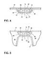
- FIG. 4is a cross-section detail view of the portion of the bladder unit indicated by section line IV-IV in FIG. 1 ;
- FIG. 5is a cross-section detail view of the portion of the bladder unit indicated by section line V-V in FIG. 1 ;
- FIG. 6is a cross-section detail view of the portion of the bladder unit indicated by section line VI-VI in FIG. 1 ;
- FIG. 7is a cross-section detail view of the portion of the bladder unit indicated by section line VII-VII in FIG. 1 ;
- FIG. 8is a perspective view of a formed lower sheet useable in a bladder unit according to an aspect of the disclosure.
- FIG. 9is an assembly view of a plurality of extruded elements having capillaries therein and a corresponding plurality of coupling assemblies between the lower sheet of FIG. 8 and an upper sheet during;
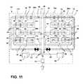
- FIG. 10is a schematic diagram of an example air flow network that can be achieved using extruded elements and coupling assemblies in a bladder unit;
- FIG. 11is a further schematic diagram of an alternative example air flow network that can also be achieved using extruded elements and coupling assemblies in a bladder unit;
- FIG. 12is a further schematic diagram of an alternative example air flow network that can also be achieved using extruded elements and coupling assemblies in a bladder unit;
- FIG. 13is a side cross-section view of a vehicle seat that can include a bladder unit according to the various aspects of the present disclosure
- FIG. 14is a further side cross-section view of the vehicle seat of FIG. 13 in a folded configuration
- FIG. 15is a side cross-section view of a valve that can be used in the bladder unit of FIG. 1 ;
- FIG. 16is a side cross-section view of the valve of FIG. 15 in an open condition.
- the terms “upper,” “lower,” “right,” “left,” “rear,” “front,” “vertical,” “horizontal,” “interior,” “exterior,” and derivatives thereofshall relate to the invention as oriented in FIG. 1 .
- the inventionmay assume various alternative orientations, except where expressly specified to the contrary.
- the specific devices and processes illustrated in the attached drawing, and described in the following specificationare simply exemplary embodiments of the inventive concepts defined in the appended claims. Hence, specific dimensions and other physical characteristics relating to the embodiments disclosed herein are not to be considered as limiting, unless the claims expressly state otherwise.
- reference numeral 10generally designates a bladder unit.
- Bladder unit 10includes an upper sheet 12 and a lower sheet 14 defining opposed portions of a first bladder 26 .
- Bladder unit 10further includes a first extruded element 16 , 18 having an upper face 20 and a lower face 22 respectively coupled with the upper sheet 12 and the lower sheet 14 along at least a portion of a first boundary 24 of the first bladder 26 .
- a first capillary 28 , 30extends through the extruded element 16 , 18 and across the portion of the first boundary 24 .
- bladder unit 10can include a number of extruded elements 16 , 18 extending in various directions and across various boundaries 24 between adjacent bladders 26 of bladder unit 10 .
- Such an arrangementcan be used to transfer air, or another fluid usable within bladder unit 10 , among the various bladders 26 (which are illustrated as bladders 26 a - 26 d and are referred to specifically in this manner, while being referred to collectively or generically as bladders 26 or bladder 26 with other features being referred to in a similar manner) according to a desired scheme for such movement or transfer.
- the various bladders 26which are illustrated as bladders 26 a - 26 d and are referred to specifically in this manner, while being referred to collectively or generically as bladders 26 or bladder 26 with other features being referred to in a similar manner
- a main extruded element 16can extend along a length 32 thereof, such length being normal to first boundary 24 a of a first bladder 26 a , such that the first capillary 28 thereof extends across boundary 24 a . Further, extruded element 16 can be configured such that the length 32 thereof extends along another boundary 24 b surrounding an additional portion of bladder 26 a that is generally normal to first boundary 24 a .
- extruded element 16can align at least a first capillary 28 so as to extend across a number of additional boundaries at least partially defined within lower sheet 14 , including boundary 24 c , which is positioned between adjacent bladders 26 a and 26 b , as well as across boundary 24 a , which is, itself, positioned between (and shared by) bladder 26 a and bladder 26 c . Still further, main extruded element 16 can also extend across boundary 24 d , which is oppositely positioned from the boundary 24 a with respect to bladder 26 c and to an exterior of bladder unit 10 . As shown, this arrangement can be achieved in bladder unit 10 due to the positioning of boundary 24 b so as to be common among adjacent bladders 26 a , 26 b , and 26 c.
- additional extruded elements 18can be used to further move air in a direction normal to the length 32 of the main extruded element 16 so as to, for example, transfer air from adjacent bladders, including bladder 26 d that are disposed across an additional boundary 24 e opposite bladder 26 a , for example, from boundary 24 b .
- such an extruded element 18can be positioned so as to cross boundary 24 e in a location that is disposed between boundaries 24 a and 24 c , as opposed to main extruded element 16 which extends along a boundary 24 b .
- Different combinations of such elements in such positionscan be used to transfer air as needed among various ones of bladders 26 and to accommodate additional features for facilitating the desired transfer of air, as discussed below.
- main extruded element 16may include one or more notches 38 therein that are cut or otherwise formed in a side thereof to expose open ends 40 of the associated capillary 28 along an intermediate portion or portions of extruded element 16 .
- Respective T-couplings 42may be positioned within notch 38 and may be coupled with the adjacent facing exposed ends 40 of the associated capillary 28 and may further couple with a tube 44 that extends away from extruded element 16 to couple with capillary 30 of extruded element 18 .
- Tube 44may include therein, or otherwise have coupled therewith, a check valve 46 to control the direction of movement of air between main extruded element 16 and bladder 26 a , for example.
- check valve 46is included and oriented so as to prevent air from flowing out of bladder 26 a and back into extruded element 16 , however other arrangements are possible.
- tube 44can further include an outlet 48 that allows the flow of air from main extruded element 16 and through check valve 46 to enter bladder 26 a . Further, outlet 48 allows for fluidic communication between bladder 26 a and bladder 26 d through capillary 30 of extruded element 18 .
- T-coupling 42can couple with a check valve 46 that is open via an outlet thereof to bladder 26 a without a portion of tube 44 coupling with capillary 30 .
- capillary 30may still provide for fluidic communication between bladder 26 a and bladder 26 d .
- tube 44it may be desirable to include tube 44 to fixedly arrange extruded elements 18 and 16 together prior to assembly with lower sheet 14 , as described below.
- a variation of check valve 46can include a cuff 50 surrounding an outlet 48 positioned beneath a portion of cuff 50 and in communication with one of T-coupling 42 or tube 44 .
- a pressure downstream of cuff 50i.e. within capillary 28
- a pressure within bladder 26when a pressure downstream of cuff 50 (i.e. within capillary 28 ) is greater than a pressure within bladder 26 , such pressure can cause outward deformation of cuff 50 thereby allowing air to flow into bladder 26 .
- the pressure within bladder 26when the pressure within bladder 26 is greater than within, for example, tube 44 , the pressure within bladder 26 can cause cuff 50 to be pressed onto outlet 48 thereby preventing flow of air from out of bladder 26 and into tube 44 .
- a cuff valvecan be used in the above-described example, wherein the portion of tube 44 between check valve 46 and capillary 30 is omitted.
- main extruded element 16can include a second capillary 52 that extends parallel with first capillary 28 in a manner generally parallel therewith. This arrangement can be used to provide for a second line of air through extruded element 16 to portions of bladder unit 10 separate from or remote from the depicted bladders 26 a , 26 b , 26 c , and 26 d .
- a further plurality of notches 38are present along extruded element 16 on a side thereof opposite the above-described notches 38 that can, in a similar manner, expose open ends 40 of second capillary 52 for connection with similar coupling assemblies to those coupling assemblies 36 described above, including by use of a T-coupling 42 , as illustrated that can extend in a direction opposite the T-coupling 42 associated with bladder 26 c .
- bladder unit 10can define a further arrangement of bladders 26 on the side of second capillary 52 to provide a flow of air to additional bladders positioned on that side of extruded element 16 .
- the above-described boundaries 24 surrounding and separating adjacent ones of bladders 26can be defined along lands 54 that are spaced above the portions of bladders 26 defined within lower sheet 14 .
- lands 54can be generally flat sections of the sheet material used to define lower sheet 14 .
- the included portions of extruded element 16 and 18 within bladder unit 10can be bonded between upper sheet 12 and lower sheet 14 along or across the respective portions of boundaries 24 by being coupled with lower sheet 14 along corresponding portions of lands 54 .
- upper sheet 12is depicted as a flat sheet such that the corresponding portions of boundary 24 associated therewith are defined by portions of upper sheet 12 that bond with either lands 54 or with extruded element 16 and 18 in areas thereof that overlie lands 54 .
- the bonding of upper sheet 12 and lower sheet 14 , in particular, with the respective extruded elements 16 and 18can vary depending on the location and orientation of extruded elements 16 and 18 with respect to cells 26 boundaries 24 and lands 54 .
- FIG. 4corresponding to the cross-sectional location depicted along line IV-IV in FIG.
- extruded element 16may interrupt the direct bonding between upper sheet 12 and lower sheet 14 that extends along the direction of boundary 24 a .
- the lower face 22 of extruded element 16may bond with lower sheet 14
- lower sheet 14may wrap around adjacent portions of extruded element 16 such that lower sheet 14 further bonds with the depicted angled side faces 56 of extruded element 16 before rejoining with upper sheet 12 along the remaining portions of land 54 .
- extruded element 16when extruded element 16 is positioned along boundary 24 b in an area adjacent bladder 26 a , extruded element 16 may be bonded with lower sheet 14 along the respective land 54 along boundary 24 b , with upper sheet 12 being bonded along upper face 20 of extruded element 16 .
- these side faces 56 of extruded element 16may further define adjacent portions of bladder 26 a with the associated bonding between upper face 20 and upper sheet 12 and lower face 22 and lower sheet 14 helping to seal the bladder 26 a in the area surrounding extruded element 16 .
- FIG. 6in the cross-sectional area of section VI-VI in FIG.
- extruded element 18when crossing boundary 24 e along land 54 , can be bonded with upper sheet 12 and lower sheet 14 in a manner similar to extruded element 16 shown in FIG. 4 .
- extruded element 18is similarly formed in a trapezoidal cross-section with upper face 20 being generally wider than lower face 22 such that lower sheet 14 can bond with upper sheet 12 in the areas outside of extruded element 18 .
- lower sheet 14can extend along side-faces 56 and away from upper sheet 12 to further extend along and bond with lower face 22 of extruded element 18 .
- the above-described arrangementsallow for the various extruded elements 16 , 18 included in bladder unit 10 to be used in place of formed-in capillaries or other passages within upper sheet 12 and lower sheet 14 for individual placed capillary lines with a more robust and reliable structure that is, further, more flexible than formed-in connections between bladders 26 .
- Such an arrangementcan allow for easier assembly of varied routing schemes within and along bladders 26 in individual bladder units 10 .
- bladder unit 10can be fabricated by first forming lower sheet 14 into the desired configuration of individual bladders 26 and surrounding lands 54 corresponding with the desired boundaries 24 between bladders 26 .
- An example of such a lower sheet 14is shown in FIG. 8 , and may be fabricated by use of a vacuum-forming process including a hot-plate vacuum-forming process in which a generally flat sheet is formed into an arrangement similar to the depicted arrangement using heat and vacuum pressure.
- a vacuum-forming processincluding a hot-plate vacuum-forming process in which a generally flat sheet is formed into an arrangement similar to the depicted arrangement using heat and vacuum pressure.
- the desired network of extruded elements 16 and 18 and coupling assemblies 36can be pre-assembled prior to being positioned in the desired location over lower sheet 14 .
- the individual extruded elements 16 , 18can be arranged in the desired locations along lower sheet 14 prior to joining thereof with the desired coupling assemblies 36 .
- the particular desired assembly processmay vary according with the various bonding techniques and/or materials, as described further below.
- a hot-plate bonding processcan be used to couple upper sheet 12 with lower sheet 14 , including the respective capture of and bonding of extruded elements 16 , 18 , simultaneously with upper sheet 12 and lower sheet 14 , as described above.
- the pre-formed lower sheet 14 and arranged network of extruded elements 16 , 18 and coupling assemblies 36can be aligned with a flat or similarly pre-formed upper sheet 12 with upper sheet 12 , subsequently, being moved into contact with lower sheet 14 and the in-place extruded elements 16 and 18 under pressure and heat.
- upper sheet 12 , lower sheet 14 and extruded elements 16 , 18can take place in a controlled manner such that the pressure among the elements causes bonding therebetween when the resulting assembly cools
- Such an assembly processis facilitated by fabricating upper sheet 12 , lower sheet 14 and extruded elements 16 , 18 of the same or similar materials, including, for example the various melting points thereof, as well as the viscosity thereof within the desired ranges of heating temperatures. Examples of such materials include low density polyethylene (“LDPE”), vinyl, and the like.
- LDPElow density polyethylene
- various types of adhesivecan be used to achieve the desired bonding among upper sheet 12 , lower sheet 14 , and extruded elements 16 , 18 .
- such adhesivecan be applied over lands 54 of lower sheet 14 prior to positioning of extruded elements 16 and 18 , with additional adhesive applied over upper faces 20 of extruded elements 16 and 18 prior to positioning of upper sheet 12 .
- an adhesivecan be a UV-activated adhesive that can allow for positioning and any needed repositioning of elements prior to activation of the adhesive and the resulting bonding among elements.
- upper sheet 12 , lower sheet 14 , and extruded elements 16 , 18can be fabricated of a transparent material.
- FIGS. 10-12schematically depict various arrangements of bladders 26 and the various capillaries 28 , 30 , 52 , along with associated check valves 46 and 62 that can be achieved using the above-described extruded elements 16 and 18 and placed between associated upper sheets 12 and lower sheets 14 .
- these various arrangements for bladder unit 10can be used in a vehicle seat 64 , as depicted in FIGS. 13 and 14 .
- the various bladder units 10can be constructed, as described further below, to allow for the transfer of air within various regions of the cushion 66 associated with seat 64 .
- bladder unit 10is positioned within an interior of cushion 68 to allow an edge region 70 of cushion 66 to move between an expanded height 72 and a compressed height 74 under alternating pressure from an occupant O and seatback 76 .
- the weight of an occupant O on central region 78 of cushion 66can cause transfer of air from, for example, bladders 26 a and 26 b to bladder 26 c to move edge 70 to the expanded height 72 to support the occupant's legs.
- FIG. 13the weight of an occupant O on central region 78 of cushion 66 can cause transfer of air from, for example, bladders 26 a and 26 b to bladder 26 c to move edge 70 to the expanded height 72 to support the occupant's legs.
- bladder unit 10may include a series of bladders 26 and associated capillaries 28 , 30 , 52 arranged in respective extruded elements 16 , 18 as described above that can be pressurized using the depicted valve 80 , which may, for example, be a Schraeder-type valve. In this manner, bladder unit 10 can be pre-pressurized to a desired level to facilitate the above-described transfer of air among bladders 26 .
- valves 62can be provided to allow or restrict movement of air between bladders 26 d and bladders 26 a , 26 b , and 26 c .
- valves 62can be included to allow for separate inflation and deflation on different sides of extruded element 16 , such as on opposite sides of a rear bench seat in a vehicle.
- Check valves 46can be arranged to prevent backflow of air from bladders 26 d into bladders 26 a , 26 b , and 26 c except through valves 62 when open.
- the opening and closing of valves 62can be linked with the position of seatback 76 such that when seatback 76 is in an upright position, valves 62 are closed, and when seatback 76 is moved toward the folded position, valves 62 are opened, thereby allowing the above-described transfer of air among bladders 26 .
- FIG. 11A similar arrangement is depicted in FIG. 11 , in which one or more air pumps 82 are further coupled with bladder unit 10 to allow for additional, active, filling of bladders 26 if needed, such as due to de-pressurization of bladder unit 10 over time.
- FIG. 12a simplified arrangement can be provided to allow for use of bladder unit 10 in a fixed state within a seat cushion 66 that is not intended to provide the above-mentioned redistribution of air under varying pressure.
- FIGS. 15 and 16a particular arrangement that can be used for valves 62 in FIGS. 10 and 11 , as described above is illustrated in which a normally open cuff valve 62 can be positioned in line along, for example, desired sections of extruded element 18 .
- a pressure chamber 86can surround both an upstream outlet 88 and a downstream inlet 90 .
- pressure chamber 86can seal off outlet 88 an inlet 90 from each other to prevent movement of air from outlet 88 to inlet 90 when pressure chamber 86 is pressurized to a level above that of upstream outlet 88 .
- pressure from outlet 88can cause outward deflection of pressure chamber to allow air to move into inlet 90 .
- the pressure within pressure chamber 86can be provided by an external arrangement including a ball, baffle, or the like that is mechanically coupled or otherwise arranged with respect to seatback 76 to control the pressurization thereof with movement of seatback 76 as described above.
- FIGS. 15 and 16show extruded element 18 being received within valve 62 , alternative arrangements are possible in which valve 62 includes respective inlets and outlets that can be positioned within capillary 30 .
- the term “coupled”in all of its forms, couple, coupling, coupled, etc. generally means the joining of two components (electrical or mechanical) directly or indirectly to one another. Such joining may be stationary in nature or movable in nature. Such joining may be achieved with the two components (electrical or mechanical) and any additional intermediate members being integrally formed as a single unitary body with one another or with the two components. Such joining may be permanent in nature or may be removable or releasable in nature unless otherwise stated.
- elements shown as integrally formedmay be constructed of multiple parts or elements shown as multiple parts may be integrally formed, the operation of the interfaces may be reversed or otherwise varied, the length or width of the structures and/or members or connector or other elements of the system may be varied, the nature or number of adjustment positions provided between the elements may be varied.
- the elements and/or assemblies of the systemmay be constructed from any of a wide variety of materials that provide sufficient strength or durability, in any of a wide variety of colors, textures, and combinations. Accordingly, all such modifications are intended to be included within the scope of the present innovations. Other substitutions, modifications, changes, and omissions may be made in the design, operating conditions, and arrangement of the desired and other exemplary embodiments without departing from the spirit of the present innovations.
Landscapes
- Engineering & Computer Science (AREA)
- General Engineering & Computer Science (AREA)
- Mechanical Engineering (AREA)
- Aviation & Aerospace Engineering (AREA)
- Transportation (AREA)
- Mattresses And Other Support Structures For Chairs And Beds (AREA)
- Air Bags (AREA)
Abstract
Description
Claims (19)
Priority Applications (3)
| Application Number | Priority Date | Filing Date | Title |
|---|---|---|---|
| US15/254,244US10391912B2 (en) | 2016-09-01 | 2016-09-01 | Lay in place capillary control system for air suspended seating |
| CN201710761791.3ACN108297773B (en) | 2016-09-01 | 2017-08-30 | Capillary control system laid in place for air suspended seats |
| DE102017120096.7ADE102017120096A1 (en) | 2016-09-01 | 2017-08-31 | PLACEABLE CAPILLARY CONTROL SYSTEM FOR AIR-SPRING SEATS |
Applications Claiming Priority (1)
| Application Number | Priority Date | Filing Date | Title |
|---|---|---|---|
| US15/254,244US10391912B2 (en) | 2016-09-01 | 2016-09-01 | Lay in place capillary control system for air suspended seating |
Publications (2)
| Publication Number | Publication Date |
|---|---|
| US20180056827A1 US20180056827A1 (en) | 2018-03-01 |
| US10391912B2true US10391912B2 (en) | 2019-08-27 |
Family
ID=61166824
Family Applications (1)
| Application Number | Title | Priority Date | Filing Date |
|---|---|---|---|
| US15/254,244Active2037-03-04US10391912B2 (en) | 2016-09-01 | 2016-09-01 | Lay in place capillary control system for air suspended seating |
Country Status (3)
| Country | Link |
|---|---|
| US (1) | US10391912B2 (en) |
| CN (1) | CN108297773B (en) |
| DE (1) | DE102017120096A1 (en) |
Families Citing this family (2)
| Publication number | Priority date | Publication date | Assignee | Title |
|---|---|---|---|---|
| US10086730B2 (en)* | 2016-09-28 | 2018-10-02 | Ford Global Technologies, Llc | Passive pressure recovery device for passive air suspended seats |
| US20250153620A1 (en)* | 2023-11-15 | 2025-05-15 | Lear Corporation | Fluid system for a vehicle seat assembly |
Citations (70)
| Publication number | Priority date | Publication date | Assignee | Title |
|---|---|---|---|---|
| US2434641A (en)* | 1946-02-20 | 1948-01-20 | Henry L Burns | Resilient seat cushion |
| US3330598A (en) | 1966-02-14 | 1967-07-11 | Whiteside George Harold | Pneumatic seat |
| US3363941A (en) | 1966-05-16 | 1968-01-16 | Way Inc | Air inflated automobile seat |
| US3730588A (en) | 1970-06-23 | 1973-05-01 | Belge Exploit Navigation Sa | Seat, couch or bed, provided with at least one vacuum cushion |
| US3792501A (en) | 1973-06-18 | 1974-02-19 | E Kery | Air chairs and convertible sofas |
| US4017118A (en) | 1976-04-19 | 1977-04-12 | Cawley Reginald E | Patient supporting device |
| US4018477A (en) | 1975-11-03 | 1977-04-19 | Uop Inc. | Adjustable height front edge for vehicle seat |
| US4145083A (en) | 1977-06-17 | 1979-03-20 | Urban Frank K | Therapeutic chair for cerebral palsy child |
| US4316631A (en) | 1979-01-24 | 1982-02-23 | Steyr-Daimler-Puch Aktiengesellschaft | Backrest |
| US4536030A (en) | 1979-08-22 | 1985-08-20 | Nissan Motor Co., Ltd. | Seat with adjustable side support device |
| US4592588A (en) | 1983-08-04 | 1986-06-03 | Tachikawa Spring Co., Ltd. | Vehicle seat |
| US4615563A (en) | 1984-11-09 | 1986-10-07 | Tachikawa Spring Co., Ltd. | Vehicle seat |
| US4629248A (en) | 1985-06-03 | 1986-12-16 | General Motors Corporation | Thigh support for vehicle seats |
| US4634179A (en) | 1982-07-31 | 1987-01-06 | Aisin Seiki Kabushiki Kaisha | Air lumbar support device |
| US4722550A (en) | 1985-08-15 | 1988-02-02 | Mazda Motor Corporation | Seat assembly for motor vehicle |
| US4761011A (en) | 1986-04-02 | 1988-08-02 | Sereboff Joel L | Water cushion stress-reducing assemblies for chairs and other seating devices |
| US4792186A (en) | 1987-11-16 | 1988-12-20 | Cooper Tire & Rubber Company | Valve for controlling two-way flow |
| US4840425A (en) | 1987-04-21 | 1989-06-20 | Tush Cush, Inc. | Varying support cushioned seating assembly and method |
| US4909568A (en) | 1987-10-16 | 1990-03-20 | Fiat Auto S.P.A. | Adjustable backrest for the seats of vehicles, particularly cars |
| US4965899A (en) | 1985-07-16 | 1990-10-30 | Okamoto Industries,Inc. | Air cushion for chair and chair utilizing the air cushion |
| US5082326A (en) | 1989-04-28 | 1992-01-21 | Okamoto Industries, Inc. | Vehicle seat with automatic adjustment mechanisms utilizing inflatable air bags |
| US5135282A (en) | 1989-08-18 | 1992-08-04 | Man Nutzfahrzeuge Aktiengesellschaft | Motor vehicle seat back |
| US5433506A (en) | 1993-11-30 | 1995-07-18 | Jensen; Hans C. | Pneumatically-cushioned chair |
| US5529377A (en) | 1993-06-25 | 1996-06-25 | Mccord Winn Texton | Air cell module for automotive seat |
| US5584085A (en) | 1989-08-24 | 1996-12-17 | Surgical Design Corporation | Support structure with motion |
| US5662384A (en) | 1995-11-14 | 1997-09-02 | Peter W. Linley | Dynamic seating support system |
| US5806928A (en) | 1997-07-14 | 1998-09-15 | Mccord Winn Textron Inc. | Inflatable air cell having improved cell-to-air tube connection |
| US5860705A (en) | 1995-09-08 | 1999-01-19 | Ridder; Everwijn Petrus Maria | Chair or armchair |
| US5879053A (en) | 1997-10-09 | 1999-03-09 | Lear Corporation | Collapsible vehicle seat assembly |
| US5927807A (en)* | 1998-05-19 | 1999-07-27 | Heller; Hilary A. | Water support device for chairs |
| US6036265A (en) | 1996-07-22 | 2000-03-14 | Schukra Manufacturing, Inc. | Shape-adjusting mechanism for backrest |
| US6203105B1 (en) | 1999-08-20 | 2001-03-20 | Mccord Winn Textron Inc. | Vehicle impact responsive multiple bladder seating and headrest system and method |
| US6206474B1 (en) | 1997-01-17 | 2001-03-27 | Bayerische Motoren Werke Aktiengesellschaft | Padding for a vehicle seat |
| US6234578B1 (en) | 1998-05-12 | 2001-05-22 | Mccord Winn Textron, Inc. | Seating assembly and method of making same |
| US6353207B1 (en) | 2000-08-17 | 2002-03-05 | Ctex Seat Comfort Ltd. | Expandable chamber having combined occupant support and heating |
| US6386633B1 (en) | 1999-05-05 | 2002-05-14 | Recaro Gmbh & Co. | Adjustable vehicle seat |
| US6450579B1 (en) | 1998-02-16 | 2002-09-17 | Ab Volvo | Foldable seat for a vehicle |
| US6554360B1 (en) | 1998-10-14 | 2003-04-29 | Grammer Ag | Seat |
| US6568754B1 (en) | 2000-10-30 | 2003-05-27 | Ford Global Technologies, Llc | Expandable, redeployable automotive headrest |
| DE10158876A1 (en) | 2001-11-30 | 2003-06-12 | Bayerische Motoren Werke Ag | Car seat, comprising inflated upholstered areas, to be deflated for folding of back part in order to increase storage space |
| US6623076B2 (en) | 1993-06-17 | 2003-09-23 | Schukra-Gerätebau AG | Adjustment apparatus for a resiliently flexible support element of a back rest |
| US6823549B1 (en) | 2003-05-14 | 2004-11-30 | Donna N. Hampton | Alternating pressure cushion with inflatable lumbar support |
| US6865825B2 (en) | 1994-04-14 | 2005-03-15 | Promdx Technology, Inc. | Ergonomic systems and methods providing intelligent adaptive surfaces and temperature control |
| DE102004017212B3 (en) | 2004-04-10 | 2005-06-02 | Faurecia Autositze Gmbh & Co. Kg | Seat for vehicle occupant has a valve controlled by folding backrest to allow air into or out of foam material |
| US6905170B2 (en) | 2003-01-22 | 2005-06-14 | L & P Property Management Company | Fold down seat lumbar support apparatus and method |
| US6912748B2 (en) | 2002-11-22 | 2005-07-05 | L & P Property Management Company | Self inflating pneumatic seat cushion apparatus and method |
| US20060061183A1 (en) | 2002-11-08 | 2006-03-23 | Johnson Controls Technology Company | Thin profile folding vehicle seat |
| US7059678B1 (en) | 2003-01-30 | 2006-06-13 | Taylor Alan R | Portable orthopedic support device |
| US7086700B2 (en) | 2003-11-03 | 2006-08-08 | Faurecia Autositze Gmbh & Co. Kg | Automobile seat |
| US7108323B2 (en) | 2001-07-18 | 2006-09-19 | Intier Automotive Inc. | Fold flat stow in floor seat assembly with collapsible bolsters |
| US7225486B2 (en) | 2005-01-10 | 2007-06-05 | Jackson Iii Avery M | Therapeutic seat cushion |
| US7311358B2 (en) | 2002-11-08 | 2007-12-25 | Johnson Controls Technology Company | Seat cushion presenter device for folding seat |
| US7364229B2 (en) | 2005-06-30 | 2008-04-29 | Hwang-Pao Lee | Automatic ventilation device for chair |
| US20080122274A1 (en) | 2006-11-28 | 2008-05-29 | Trevor Edwards | Aircraft seat cover assembly |
| US7490900B2 (en) | 2006-03-25 | 2009-02-17 | Faurecia Autosize Gmbh | Vehicle seat |
| US20100207443A1 (en) | 2009-02-19 | 2010-08-19 | Faurecia Automotive Seating, Inc. | Vehicle seat cushion with inflatable air bladder |
| US7874618B2 (en) | 2005-04-15 | 2011-01-25 | Grammer Ag | Vehicle seat with a deformable backrest |
| US20110266855A1 (en) | 2009-01-06 | 2011-11-03 | Magna Seating Inc. | Inflatable Thin Seat |
| US8181292B1 (en)* | 2009-09-15 | 2012-05-22 | The United States Of America As Represented By The Secretary Of The Air Force | Seat cushion |
| US8261387B2 (en)* | 2006-02-10 | 2012-09-11 | Joerns Llc | Self inflating air mattress |
| US8275514B2 (en) | 2008-11-13 | 2012-09-25 | Hyundai Motor Company | Intelligent vehicle seat support system |
| US20130062920A1 (en) | 2011-09-14 | 2013-03-14 | Ron McDiarmid | Chair with inflatable bladder system |
| US8460502B2 (en)* | 2011-04-14 | 2013-06-11 | Spirit Aerosystems, Inc. | Method and tooling for manufacture of co-cured composite structures |
| US8510884B2 (en) | 2009-02-20 | 2013-08-20 | Comfort Concepts Pty Limited | Pneumatic seat cushion system |
| US20130285426A1 (en) | 2012-04-30 | 2013-10-31 | Ford Global Technologies, Llc | Adjustable firmness vehicle seat |
| US8827371B2 (en) | 2009-12-02 | 2014-09-09 | Faurecia Automotive Seating, Llc | Vehicle seat cushion with inflatable support |
| US20150008710A1 (en) | 2013-07-03 | 2015-01-08 | Bam Labs, Inc. | Smart seat monitoring system |
| US20150126926A1 (en) | 2012-04-10 | 2015-05-07 | Carebay Europe Ltd | Infusion Device |
| US20150143636A1 (en)* | 2012-10-19 | 2015-05-28 | Jeffrey W. Wilkinson | Cushioning device and method of cushioning a body |
| US20150230803A1 (en)* | 2013-02-20 | 2015-08-20 | Richard Hill Schreckengaust | Rapid application tourniquet |
Family Cites Families (7)
| Publication number | Priority date | Publication date | Assignee | Title |
|---|---|---|---|---|
| US2724129A (en)* | 1953-03-06 | 1955-11-22 | John G Pugh | Compartmented inflatable articles and the like and method for making the same |
| JP3782254B2 (en)* | 1999-04-14 | 2006-06-07 | 東芝テック株式会社 | Air massage machine |
| JP2007105260A (en)* | 2005-10-14 | 2007-04-26 | Delta Tooling Co Ltd | Air cushion |
| CN201370335Y (en)* | 2009-02-25 | 2009-12-30 | 李竞 | Wave mattress with extensible ballonets |
| KR101346813B1 (en)* | 2011-08-03 | 2014-01-02 | (주) 더웰 | Mold For Manufacturing Air Mat |
| US9211017B2 (en)* | 2012-08-01 | 2015-12-15 | Sealy Technology, Llc | Air flow mattress constructions and variable density mattress cores |
| KR101529134B1 (en)* | 2013-08-27 | 2015-06-16 | 함의신 | Cushion imbedded self inflated air tube and method for manufacturing the same |
- 2016
- 2016-09-01USUS15/254,244patent/US10391912B2/enactiveActive
- 2017
- 2017-08-30CNCN201710761791.3Apatent/CN108297773B/enactiveActive
- 2017-08-31DEDE102017120096.7Apatent/DE102017120096A1/enactivePending
Patent Citations (73)
| Publication number | Priority date | Publication date | Assignee | Title |
|---|---|---|---|---|
| US2434641A (en)* | 1946-02-20 | 1948-01-20 | Henry L Burns | Resilient seat cushion |
| US3330598A (en) | 1966-02-14 | 1967-07-11 | Whiteside George Harold | Pneumatic seat |
| US3363941A (en) | 1966-05-16 | 1968-01-16 | Way Inc | Air inflated automobile seat |
| US3730588A (en) | 1970-06-23 | 1973-05-01 | Belge Exploit Navigation Sa | Seat, couch or bed, provided with at least one vacuum cushion |
| US3792501A (en) | 1973-06-18 | 1974-02-19 | E Kery | Air chairs and convertible sofas |
| US4018477A (en) | 1975-11-03 | 1977-04-19 | Uop Inc. | Adjustable height front edge for vehicle seat |
| US4017118A (en) | 1976-04-19 | 1977-04-12 | Cawley Reginald E | Patient supporting device |
| US4145083A (en) | 1977-06-17 | 1979-03-20 | Urban Frank K | Therapeutic chair for cerebral palsy child |
| US4316631A (en) | 1979-01-24 | 1982-02-23 | Steyr-Daimler-Puch Aktiengesellschaft | Backrest |
| US4536030A (en) | 1979-08-22 | 1985-08-20 | Nissan Motor Co., Ltd. | Seat with adjustable side support device |
| US4634179A (en) | 1982-07-31 | 1987-01-06 | Aisin Seiki Kabushiki Kaisha | Air lumbar support device |
| US4592588A (en) | 1983-08-04 | 1986-06-03 | Tachikawa Spring Co., Ltd. | Vehicle seat |
| US4615563A (en) | 1984-11-09 | 1986-10-07 | Tachikawa Spring Co., Ltd. | Vehicle seat |
| US4629248A (en) | 1985-06-03 | 1986-12-16 | General Motors Corporation | Thigh support for vehicle seats |
| US4965899A (en) | 1985-07-16 | 1990-10-30 | Okamoto Industries,Inc. | Air cushion for chair and chair utilizing the air cushion |
| US4722550A (en) | 1985-08-15 | 1988-02-02 | Mazda Motor Corporation | Seat assembly for motor vehicle |
| US4761011A (en) | 1986-04-02 | 1988-08-02 | Sereboff Joel L | Water cushion stress-reducing assemblies for chairs and other seating devices |
| US4840425A (en) | 1987-04-21 | 1989-06-20 | Tush Cush, Inc. | Varying support cushioned seating assembly and method |
| US4909568A (en) | 1987-10-16 | 1990-03-20 | Fiat Auto S.P.A. | Adjustable backrest for the seats of vehicles, particularly cars |
| US4792186A (en) | 1987-11-16 | 1988-12-20 | Cooper Tire & Rubber Company | Valve for controlling two-way flow |
| US5082326A (en) | 1989-04-28 | 1992-01-21 | Okamoto Industries, Inc. | Vehicle seat with automatic adjustment mechanisms utilizing inflatable air bags |
| US5135282A (en) | 1989-08-18 | 1992-08-04 | Man Nutzfahrzeuge Aktiengesellschaft | Motor vehicle seat back |
| US5584085A (en) | 1989-08-24 | 1996-12-17 | Surgical Design Corporation | Support structure with motion |
| US6623076B2 (en) | 1993-06-17 | 2003-09-23 | Schukra-Gerätebau AG | Adjustment apparatus for a resiliently flexible support element of a back rest |
| US5529377A (en) | 1993-06-25 | 1996-06-25 | Mccord Winn Texton | Air cell module for automotive seat |
| US5433506A (en) | 1993-11-30 | 1995-07-18 | Jensen; Hans C. | Pneumatically-cushioned chair |
| US6865825B2 (en) | 1994-04-14 | 2005-03-15 | Promdx Technology, Inc. | Ergonomic systems and methods providing intelligent adaptive surfaces and temperature control |
| US5860705A (en) | 1995-09-08 | 1999-01-19 | Ridder; Everwijn Petrus Maria | Chair or armchair |
| US5662384A (en) | 1995-11-14 | 1997-09-02 | Peter W. Linley | Dynamic seating support system |
| US6036265A (en) | 1996-07-22 | 2000-03-14 | Schukra Manufacturing, Inc. | Shape-adjusting mechanism for backrest |
| US6206474B1 (en) | 1997-01-17 | 2001-03-27 | Bayerische Motoren Werke Aktiengesellschaft | Padding for a vehicle seat |
| US5806928A (en) | 1997-07-14 | 1998-09-15 | Mccord Winn Textron Inc. | Inflatable air cell having improved cell-to-air tube connection |
| US5879053A (en) | 1997-10-09 | 1999-03-09 | Lear Corporation | Collapsible vehicle seat assembly |
| US6450579B1 (en) | 1998-02-16 | 2002-09-17 | Ab Volvo | Foldable seat for a vehicle |
| US6234578B1 (en) | 1998-05-12 | 2001-05-22 | Mccord Winn Textron, Inc. | Seating assembly and method of making same |
| US5927807A (en)* | 1998-05-19 | 1999-07-27 | Heller; Hilary A. | Water support device for chairs |
| US6554360B1 (en) | 1998-10-14 | 2003-04-29 | Grammer Ag | Seat |
| US6386633B1 (en) | 1999-05-05 | 2002-05-14 | Recaro Gmbh & Co. | Adjustable vehicle seat |
| US6203105B1 (en) | 1999-08-20 | 2001-03-20 | Mccord Winn Textron Inc. | Vehicle impact responsive multiple bladder seating and headrest system and method |
| US6353207B1 (en) | 2000-08-17 | 2002-03-05 | Ctex Seat Comfort Ltd. | Expandable chamber having combined occupant support and heating |
| US6568754B1 (en) | 2000-10-30 | 2003-05-27 | Ford Global Technologies, Llc | Expandable, redeployable automotive headrest |
| US7108323B2 (en) | 2001-07-18 | 2006-09-19 | Intier Automotive Inc. | Fold flat stow in floor seat assembly with collapsible bolsters |
| DE10158876A1 (en) | 2001-11-30 | 2003-06-12 | Bayerische Motoren Werke Ag | Car seat, comprising inflated upholstered areas, to be deflated for folding of back part in order to increase storage space |
| US20060061183A1 (en) | 2002-11-08 | 2006-03-23 | Johnson Controls Technology Company | Thin profile folding vehicle seat |
| US7311358B2 (en) | 2002-11-08 | 2007-12-25 | Johnson Controls Technology Company | Seat cushion presenter device for folding seat |
| US7255399B2 (en) | 2002-11-08 | 2007-08-14 | Johnson Controls Technology Company | Thin profile folding vehicle seat |
| US6912748B2 (en) | 2002-11-22 | 2005-07-05 | L & P Property Management Company | Self inflating pneumatic seat cushion apparatus and method |
| US6905170B2 (en) | 2003-01-22 | 2005-06-14 | L & P Property Management Company | Fold down seat lumbar support apparatus and method |
| US7059678B1 (en) | 2003-01-30 | 2006-06-13 | Taylor Alan R | Portable orthopedic support device |
| US6823549B1 (en) | 2003-05-14 | 2004-11-30 | Donna N. Hampton | Alternating pressure cushion with inflatable lumbar support |
| US7086700B2 (en) | 2003-11-03 | 2006-08-08 | Faurecia Autositze Gmbh & Co. Kg | Automobile seat |
| DE102004017212B3 (en) | 2004-04-10 | 2005-06-02 | Faurecia Autositze Gmbh & Co. Kg | Seat for vehicle occupant has a valve controlled by folding backrest to allow air into or out of foam material |
| US7225486B2 (en) | 2005-01-10 | 2007-06-05 | Jackson Iii Avery M | Therapeutic seat cushion |
| US7874618B2 (en) | 2005-04-15 | 2011-01-25 | Grammer Ag | Vehicle seat with a deformable backrest |
| US7364229B2 (en) | 2005-06-30 | 2008-04-29 | Hwang-Pao Lee | Automatic ventilation device for chair |
| US8261387B2 (en)* | 2006-02-10 | 2012-09-11 | Joerns Llc | Self inflating air mattress |
| US7490900B2 (en) | 2006-03-25 | 2009-02-17 | Faurecia Autosize Gmbh | Vehicle seat |
| US20080122274A1 (en) | 2006-11-28 | 2008-05-29 | Trevor Edwards | Aircraft seat cover assembly |
| US8275514B2 (en) | 2008-11-13 | 2012-09-25 | Hyundai Motor Company | Intelligent vehicle seat support system |
| US8944504B2 (en) | 2009-01-06 | 2015-02-03 | Magna Seating Inc | Inflatable thin seat |
| US20110266855A1 (en) | 2009-01-06 | 2011-11-03 | Magna Seating Inc. | Inflatable Thin Seat |
| US20100207443A1 (en) | 2009-02-19 | 2010-08-19 | Faurecia Automotive Seating, Inc. | Vehicle seat cushion with inflatable air bladder |
| US8510884B2 (en) | 2009-02-20 | 2013-08-20 | Comfort Concepts Pty Limited | Pneumatic seat cushion system |
| US8181292B1 (en)* | 2009-09-15 | 2012-05-22 | The United States Of America As Represented By The Secretary Of The Air Force | Seat cushion |
| US8827371B2 (en) | 2009-12-02 | 2014-09-09 | Faurecia Automotive Seating, Llc | Vehicle seat cushion with inflatable support |
| US8460502B2 (en)* | 2011-04-14 | 2013-06-11 | Spirit Aerosystems, Inc. | Method and tooling for manufacture of co-cured composite structures |
| US20130062920A1 (en) | 2011-09-14 | 2013-03-14 | Ron McDiarmid | Chair with inflatable bladder system |
| US20150126926A1 (en) | 2012-04-10 | 2015-05-07 | Carebay Europe Ltd | Infusion Device |
| US20130285426A1 (en) | 2012-04-30 | 2013-10-31 | Ford Global Technologies, Llc | Adjustable firmness vehicle seat |
| US9211824B2 (en) | 2012-04-30 | 2015-12-15 | Ford Global Technologies, Llc | Adjustable firmness vehicle seat |
| US20150143636A1 (en)* | 2012-10-19 | 2015-05-28 | Jeffrey W. Wilkinson | Cushioning device and method of cushioning a body |
| US20150230803A1 (en)* | 2013-02-20 | 2015-08-20 | Richard Hill Schreckengaust | Rapid application tourniquet |
| US20150008710A1 (en) | 2013-07-03 | 2015-01-08 | Bam Labs, Inc. | Smart seat monitoring system |
Also Published As
| Publication number | Publication date |
|---|---|
| DE102017120096A1 (en) | 2018-03-01 |
| US20180056827A1 (en) | 2018-03-01 |
| CN108297773A (en) | 2018-07-20 |
| CN108297773B (en) | 2022-03-29 |
Similar Documents
| Publication | Publication Date | Title |
|---|---|---|
| US10744920B2 (en) | Method for customizing a vehicle seat | |
| US10214129B2 (en) | Air bladder with stacked cell system | |
| US20180361897A1 (en) | Vehicle seat padding assembly with molded-in bladders | |
| US10752145B2 (en) | Pneumatic device | |
| CN110774954B (en) | Ventilation device for vehicle seat and variable ventilation seat using the same | |
| DE112010004064T5 (en) | VEHICLE SEAT CUSHION WITH VENTILATORY SUPPORT | |
| JP4999455B2 (en) | Seat ventilators and seats | |
| US20140230921A1 (en) | Adjusting device for a vehicle component | |
| US20180008507A1 (en) | Massage cell arrangement and massage cell system | |
| US20150165940A1 (en) | Adjustment element for a vehicle seat | |
| WO2008057962A3 (en) | Chair with air conditioning device | |
| US20140167460A1 (en) | Control Element for a Vehicle Seat | |
| US10391912B2 (en) | Lay in place capillary control system for air suspended seating | |
| CN106427706A (en) | Multi-cell seat cushion assembly | |
| JP7427892B2 (en) | Air bags and vehicle seat devices | |
| JP6347220B2 (en) | Vehicle seat support device | |
| US10351034B2 (en) | Pressure medium distributor, pnuematic adjustment arrangement for a vehicle seat, vehicle seat, and method for producing a pressure medium distributor for a pneumatic adjustment arrangement | |
| JP2017128144A (en) | Bag body device for vehicular seat | |
| US12337738B2 (en) | Fluid system for a vehicle seat assembly | |
| CN214112355U (en) | Seat capable of adjusting lumbar support | |
| US20250153620A1 (en) | Fluid system for a vehicle seat assembly | |
| JP6519318B2 (en) | Vehicle seat fluid bag device | |
| JP6699767B2 (en) | Fluid bag device for vehicle seats |
Legal Events
| Date | Code | Title | Description |
|---|---|---|---|
| AS | Assignment | Owner name:FORD GLOBAL TECHNOLOGIES, LLC, MICHIGAN Free format text:ASSIGNMENT OF ASSIGNORS INTEREST;ASSIGNOR:DRY, ALAN GEORGE;REEL/FRAME:039899/0923 Effective date:20160901 | |
| STPP | Information on status: patent application and granting procedure in general | Free format text:RESPONSE TO NON-FINAL OFFICE ACTION ENTERED AND FORWARDED TO EXAMINER | |
| STPP | Information on status: patent application and granting procedure in general | Free format text:NOTICE OF ALLOWANCE MAILED -- APPLICATION RECEIVED IN OFFICE OF PUBLICATIONS | |
| STPP | Information on status: patent application and granting procedure in general | Free format text:AWAITING TC RESP., ISSUE FEE NOT PAID | |
| STPP | Information on status: patent application and granting procedure in general | Free format text:AWAITING TC RESP, ISSUE FEE PAYMENT RECEIVED | |
| STPP | Information on status: patent application and granting procedure in general | Free format text:AWAITING TC RESP, ISSUE FEE PAYMENT VERIFIED | |
| STPP | Information on status: patent application and granting procedure in general | Free format text:PUBLICATIONS -- ISSUE FEE PAYMENT VERIFIED | |
| STCF | Information on status: patent grant | Free format text:PATENTED CASE | |
| MAFP | Maintenance fee payment | Free format text:PAYMENT OF MAINTENANCE FEE, 4TH YEAR, LARGE ENTITY (ORIGINAL EVENT CODE: M1551); ENTITY STATUS OF PATENT OWNER: LARGE ENTITY Year of fee payment:4 |