US10391368B2 - Golf club with movable weight - Google Patents
Golf club with movable weightDownload PDFInfo
- Publication number
- US10391368B2 US10391368B2US16/046,789US201816046789AUS10391368B2US 10391368 B2US10391368 B2US 10391368B2US 201816046789 AUS201816046789 AUS 201816046789AUS 10391368 B2US10391368 B2US 10391368B2
- Authority
- US
- United States
- Prior art keywords
- weight
- retainer
- receptacle
- golf club
- rotating portion
- Prior art date
- Legal status (The legal status is an assumption and is not a legal conclusion. Google has not performed a legal analysis and makes no representation as to the accuracy of the status listed.)
- Active
Links
Images


Classifications
- A—HUMAN NECESSITIES
- A63—SPORTS; GAMES; AMUSEMENTS
- A63B—APPARATUS FOR PHYSICAL TRAINING, GYMNASTICS, SWIMMING, CLIMBING, OR FENCING; BALL GAMES; TRAINING EQUIPMENT
- A63B53/00—Golf clubs
- A63B53/04—Heads
- A63B53/0466—Heads wood-type
- A—HUMAN NECESSITIES
- A63—SPORTS; GAMES; AMUSEMENTS
- A63B—APPARATUS FOR PHYSICAL TRAINING, GYMNASTICS, SWIMMING, CLIMBING, OR FENCING; BALL GAMES; TRAINING EQUIPMENT
- A63B53/00—Golf clubs
- A63B53/04—Heads
- A63B53/047—Heads iron-type
- A—HUMAN NECESSITIES
- A63—SPORTS; GAMES; AMUSEMENTS
- A63B—APPARATUS FOR PHYSICAL TRAINING, GYMNASTICS, SWIMMING, CLIMBING, OR FENCING; BALL GAMES; TRAINING EQUIPMENT
- A63B60/00—Details or accessories of golf clubs, bats, rackets or the like
- A63B60/02—Ballast means for adjusting the centre of mass
- A—HUMAN NECESSITIES
- A63—SPORTS; GAMES; AMUSEMENTS
- A63B—APPARATUS FOR PHYSICAL TRAINING, GYMNASTICS, SWIMMING, CLIMBING, OR FENCING; BALL GAMES; TRAINING EQUIPMENT
- A63B60/00—Details or accessories of golf clubs, bats, rackets or the like
- A63B60/52—Details or accessories of golf clubs, bats, rackets or the like with slits
- A63B2053/0433—
- A—HUMAN NECESSITIES
- A63—SPORTS; GAMES; AMUSEMENTS
- A63B—APPARATUS FOR PHYSICAL TRAINING, GYMNASTICS, SWIMMING, CLIMBING, OR FENCING; BALL GAMES; TRAINING EQUIPMENT
- A63B53/00—Golf clubs
- A63B53/04—Heads
- A63B2053/0491—Heads with added weights, e.g. changeable, replaceable
- A—HUMAN NECESSITIES
- A63—SPORTS; GAMES; AMUSEMENTS
- A63B—APPARATUS FOR PHYSICAL TRAINING, GYMNASTICS, SWIMMING, CLIMBING, OR FENCING; BALL GAMES; TRAINING EQUIPMENT
- A63B53/00—Golf clubs
- A63B53/04—Heads
- A63B53/0433—Heads with special sole configurations
- A—HUMAN NECESSITIES
- A63—SPORTS; GAMES; AMUSEMENTS
- A63B—APPARATUS FOR PHYSICAL TRAINING, GYMNASTICS, SWIMMING, CLIMBING, OR FENCING; BALL GAMES; TRAINING EQUIPMENT
- A63B53/00—Golf clubs
- A63B53/04—Heads
- A63B53/06—Heads adjustable
Definitions
- This present technologygenerally relates to systems, devices, and methods related to golf clubs, and more specifically to golf club heads having movable weights.
- the trend of lengthening golf courses to increase their difficultyhas resulted in a high percentage of amateur golfers constantly searching for ways to achieve more distance from their golf shots.
- the golf industryhas responded by providing golf clubs specifically designed with distance and accuracy in mind.
- the size of wood-type golf club headshas generally been increased while multi-material construction and reduced wall thicknesses have been included to provide more mass available for selective placement through the head.
- the discretionary mass placementhas allowed the club to possess a higher moment of inertia (MOI), which translates to a greater ability to resist twisting during off-center ball impacts and less of a distance penalty for those off-center ball impacts.
- discretionary mass placementhas allowed the club to more optimally locate the center of gravity (CG) of the golf club head, and sometimes make that CG location adjustable through the use of adjustable and/or moveable weights.
- CGcenter of gravity
- Various methodsare used to selectively locate mass throughout golf club heads, including thickening portions of the body casting itself or strategically adding separate weight elements during the manufacture of the club head.
- An exampleshown in U.S. Pat. No. 7,186,190, discloses a golf club head comprising a number of moveable weights attached to the body of the club head.
- the club headincludes a number of threaded ports into which the moveable weights are screwed.
- the mass characteristics of the golf clubmay be manipulated by rearranging the moveable weights, the cylindrical shape of the weights and the receiving features within the golf club body necessarily moves a significant portion of the mass toward the center of the club head, which may not maximize the peripheral weight of the club head or the MOI.
- Alternative approaches for selectively locating mass in a club headutilize composite multi-material structures. These composite structures utilize two, three, or more materials that have different physical properties including different densities.
- An example of this type of composite club headis shown in U.S. Pat. No. 5,720,674.
- the club headcomprises an arcuate portion of high-density material bonded to a recess in the back-skirt. Because composite materials like those found in the club head must be bonded together, for example by welding, swaging, or using bonding agents such as epoxy, they may be subject to delamination or corrosion over time. This component delamination or corrosion results in decreased performance in the golf club head and can lead to club head failure.
- One aspect of the present technologyis the realization that position of weight elements in existing golf club head designs are not easily adjustable. Thus, there exists a need for an improved golf club head.
- the present inventionis directed to an improved weighting system for golf clubs that increases the club's playability.
- the present technologyis directed to a golf club head incorporating a position adjustable weight system.
- the position adjustable weight systemprovides the ability to fine tune the performance characteristics of the golf club via manipulation of the position of an adjustable weight, thereby manipulating the location of the center of gravity and the moment of inertia of the golf club to suit the golfer's preference and increase the club's playability.
- a golf club headincluding: a body having a face, a sole, a crown, and a skirt joining the face, sole, and crown; a hollow golf club interior within the body; the body having an exterior surface opposite the hollow golf club interior; the body having a center of gravity; wherein the body comprises an elongate weight receptacle; a weight retainer located in the weight receptacle; wherein the weight receptacle comprises a plurality of weight mounts; wherein each of the plurality of weight mounts comprises a recess, and wherein the recess comprises a locking wall; wherein the weight retainer is configured to slide along the weight receptacle between each of the plurality of weight mounts when the weight retainer is unlocked, and wherein the weight retainer is configured to reside in any of the plurality of weight mounts when the weight retainer is locked; wherein the weight receptacle comprises a pair of locking rails running along each side of the weight recepta
- the weight receptaclecomprises a weight port configured to receive a weight member, the weight port formed in a floor of the weight receptacle adjacent the hollow golf club interior
- the recesses of the weight receptacle installation featurecomprise a central protrusion
- the weight retainercomprises a weight retainer installation feature configured to clear the central protrusion when installing the weight retainer in the weight receptacle.
- the weight receptacle installation featureis located between two of the plurality of weight mounts, wherein the two of the plurality of weight mounts are located adjacent one another.
- the weight retainercomprises a rotating portion and a non-rotating portion, the rotating portion rotatably affixed to the non-rotating portion, and wherein rotating less than 100 degrees of rotation of the rotating portion in a first direction relative to the non-rotating portion locks the weight retainer, and wherein less than 100 degrees of rotation of the rotating portion in a second direction relative to the non-rotating portion unlocks the weight retainer.
- a golf club headincluding: a body having a face, a sole, a crown, and a skirt joining the face, sole, and crown; a hollow golf club interior within the body; the body having an exterior surface opposite the hollow golf club interior; the body having a center of gravity; wherein the body comprises an elongate weight receptacle; a weight retainer located in the weight receptacle; wherein the weight receptacle comprises a plurality of weight mounts; wherein each of the plurality of weight mounts comprises a recess, and wherein the recess comprises a locking wall; wherein the weight retainer is configured to slide along the weight receptacle between each of the plurality of weight mounts when the weight retainer is unlocked, and wherein the weight retainer is configured to reside in any of the plurality of weight mounts when the weight retainer is locked; wherein the weight receptacle comprises a pair of locking rails running along each side of the weight recepta
- the weight receptaclecomprises a weight port configured to receive a weight member, the weight port formed in a floor of the weight receptacle adjacent the hollow golf club interior
- the recess of the weight receptacle installation featurecomprises a central protrusion
- the weight retainercomprises a weight retainer installation feature configured to clear the central protrusion when installing the weight retainer in the weight receptacle.
- the weight receptacle installation featureis located between two of the plurality of weight mounts, wherein the two of the plurality of weight mounts are located adjacent one another.
- the weight receptacle installation featurecomprises recesses formed in each of the pair of locking rails.
- the weight retainercomprises a rotating portion and a non-rotating portion, the rotating portion rotatably affixed to the non-rotating portion, and wherein rotating less than 100 degrees of rotation of the rotating portion in a first direction relative to the non-rotating portion locks the weight retainer, and wherein less than 100 degrees of rotation of the rotating portion in a second direction relative to the non-rotating portion unlocks the weight retainer.
- a golf club headincluding: a body having a face, a sole, a crown, and a skirt joining the face, sole, and crown; a hollow golf club interior within the body; the body having an exterior surface opposite the hollow golf club interior; the body having a center of gravity; wherein the body comprises an elongate weight receptacle; a weight retainer located in the weight receptacle; wherein the weight receptacle comprises a plurality of weight mounts; wherein the weight retainer is configured to slide along the weight receptacle between each of the plurality of weight mounts when the weight retainer is unlocked, and wherein the weight retainer is configured to reside in any of the plurality of weight mounts when the weight retainer is locked; and wherein the weight receptacle comprises a weight receptacle installation feature configured to receive the weight retainer, wherein the weight receptacle installation feature is located between two of the plurality of weight mounts, wherein the two of the
- the weight receptaclecomprises a weight port configured to receive a weight member, the weight port formed in a floor of the weight receptacle adjacent the hollow golf club interior
- the recesses of the weight receptacle installation featurecomprises a central protrusion
- the weight retainercomprises a weight retainer installation feature configured to clear the central protrusion when installing the weight retainer in the weight receptacle.
- the weight receptacle installation featureis located between two of the plurality of weight mounts, wherein the two of the plurality of weight mounts are located adjacent one another.
- each of the plurality of weight mountscomprises a recess, and wherein the recess comprises a locking wall.
- the weight receptaclecomprises a pair of locking rails running along each side of the weight receptacle and a channel formed between the locking rails, wherein the pair of locking rails comprise thick portions and thin portions, the thin portions located adjacent the recesses, and wherein the locking walls are formed between the thin portions and the thick portions.
- the weight receptacle installation featurecomprises a recess formed in one of the pair of locking rails.
- the weight receptacle installation featurecomprises recesses formed in each of the pair of locking rails.
- the weight retainercomprises a rotating portion and a non-rotating portion, the rotating portion rotatably affixed to the non-rotating portion, and wherein rotating less than 100 degrees of rotation of the rotating portion in a first direction relative to the non-rotating portion locks the weight retainer, and wherein less than 100 degrees of rotation of the rotating portion in a second direction relative to the non-rotating portion unlocks the weight retainer.
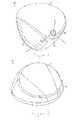
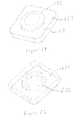
- FIG. 1illustrates a perspective view of a golf club head.
- FIG. 2illustrates a perspective view of the bottom of the golf club head of FIG. 1 .
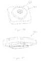
- FIG. 3illustrates a perspective view of the bottom of the golf club head including a plurality of weight members received in weight mounts.
- FIG. 4illustrates a perspective view of the bottom of an additional embodiment of the golf club head including a plurality of weight members received in weight mounts.
- FIG. 5illustrates a perspective view of one embodiment of a weight retainer locked in a weight mount.
- FIG. 6illustrates a perspective view of the weight mount of FIG. 5 .
- FIG. 7illustrates a perspective view of the weight retainer of FIG. 5 .
- FIG. 8illustrates a top view of the weight retainer of FIG. 5 .
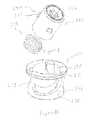
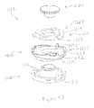
- FIG. 9illustrates a perspective view of one embodiment of a weight retainer and spring.
- FIG. 10illustrates a perspective view of one embodiment of a weight mount.
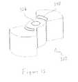
- FIG. 11illustrates a perspective view of an additional embodiment of a weight mount.
- FIG. 12illustrates an additional perspective view the weight mount of FIG. 11 .
- FIG. 13illustrates a perspective view of an additional embodiment of a weight retainer.
- FIG. 14illustrates a top view of the weight retainer of FIG. 13 in an unlocked position inside the weight mount of FIG. 11 .
- FIG. 15illustrates a top view of the weight retainer of FIG. 13 in a locked position inside the weight mount of FIG. 11 .
- FIG. 16illustrates a perspective view of one embodiment of a spring.
- FIG. 17illustrates a side view of the spring of FIG. 16 .
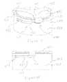
- FIG. 18illustrates a perspective view of additional embodiments of a weight member retained by a weight retainer in a weight mount.
- FIG. 19illustrates a side view of the weight member, weight retainer, and weight mount illustrated in FIG. 18 .
- FIG. 20illustrates a perspective view of additional embodiments of a weight member, weight retainer, and weight mount.
- FIG. 21illustrates a side view of the weight member, weight retainer, and weight mount of FIG. 20 .
- FIG. 22illustrates a perspective view of the weight member and weight retainer of FIG. 20 .
- FIG. 23illustrates a perspective view of the weight mount of FIG. 20 .
- FIG. 24illustrates an external perspective view of additional embodiments of a weight retainer locked in a weight mount.
- FIG. 25illustrates an internal perspective view of the weight retainer and weight mount of FIG. 24 .
- FIG. 26illustrates a perspective view of the weight retainer of FIG. 24 .
- FIG. 27illustrates an internal perspective view of the weight mount of FIG. 24 .
- FIG. 28illustrates an external top view of the weight mount of FIG. 24 .
- FIG. 29illustrates a side view of the weight retainer of FIG. 24 .
- FIG. 30illustrates a cross-sectional view of the weight retainer locked in the weight mount of FIG. 24 .
- FIG. 31illustrates a top view of an additional embodiment of a weight member locked in a weight mount.
- FIG. 32illustrates a top view of an additional embodiment of a weight member locked in a weight mount.
- FIG. 33illustrates an external perspective view of an additional embodiment of a weight retainer and weight member locked in a weight mount.
- FIG. 34illustrates a perspective view of the weight retainer and weight member of FIG. 33 .
- FIG. 35illustrates a perspective view of the weight member of FIG. 34 .
- FIG. 36illustrates a perspective view of the weight retainer of FIG. 34 .
- FIG. 37illustrates a perspective view of the weight mount of FIG. 33 .
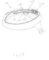
- FIG. 38illustrates a perspective view of one embodiment of a golf club head with a weight receptacle.
- FIG. 39illustrates a perspective view of an additional embodiment of a golf club head with a weight receptacle.
- FIG. 40illustrates an additional embodiment of a golf club head.
- FIG. 41illustrates a cross-sectional view of the golf club head and weight receptacle of FIG. 40 .
- FIG. 42illustrates an additional cross-sectional view of the golf club head and weight receptacle of FIG. 40 .
- FIG. 43illustrates one embodiment of an unlocked weight retainer in weight mount in a weight receptacle.
- FIG. 44illustrates a perspective view of the weight retainer of FIG. 43 .
- FIG. 45illustrates an additional perspective view of the weight retainer of FIG. 43 .
- FIG. 46illustrates an exploded view of the weight retainer of FIG. 43 .
- FIG. 47illustrates an inverted exploded view of the weight retainer of FIG. 43 .
- FIG. 48illustrates a perspective view of an additional embodiment of a weight retainer.
- FIG. 49illustrates a perspective view of the underside of the weight retainer of FIG. 48 .
- FIG. 50illustrates a perspective view of an additional embodiment of a weight receptacle.
- FIG. 51illustrates a perspective view of the weight retainer of FIG. 48 locked in the weight receptacle of FIG. 50 .
- FIG. 52illustrates a top view of the weight retainer and weight receptacle of FIG. 51 .
- FIG. 53illustrates a cross-sectional view of the weight retainer and weight receptacle of FIG. 51 .
- FIG. 54illustrates an additional perspective view of the weight retainer and weight receptacle of FIG. 51 .
- FIG. 55illustrates a perspective view of an additional embodiment of a weight retainer 2122 .
- FIG. 56illustrates an end view of the weigh retainer locked in an additional embodiment of a weight receptacle.
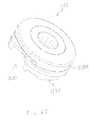
- FIG. 57illustrates a perspective view of an additional embodiment of a weight retainer.
- FIG. 58illustrates a perspective view of a portion of an additional embodiment of a weight receptacle.
- FIG. 59illustrates an end view of the weight retainer of FIG. 57 locked in the weight receptacle of FIG. 58 .
- FIG. 60illustrates a perspective view of an additional embodiment of a golf club head.
- FIG. 61illustrates the golf club head 1110 of FIG. 60 including a weight retainer and a weight member.
- FIG. 62illustrates a cross-sectional view of the golf club head of FIG. 61 .
- FIG. 63illustrates a perspective view of the weight retainer of FIG. 61 .
- FIG. 64illustrates an additional perspective view of the weight retainer of FIG. 61 .
- FIG. 65illustrates a detail view of a portion of the weight receptacle of the golf club head of FIG. 60 .
- FIG. 66illustrates a perspective view of an additional embodiment of a golf club head.
- FIG. 67illustrates a bottom view of the golf club head of FIG. 66 .
- the golf club head of the present inventionis preferably hollow, such as a metal wood type golf club head, but may include any club head type, such as iron-type club heads.
- the golf club headgenerally includes a hosel, a striking face, a crown, a sole, and a skirt that combine to define a hollow interior cavity.
- the inventive golf club headalso has a low profiled weight member disposed on a portion of the club head, and preferably on the crown, sole and/or skirt of the golf club head.
- the embodiments described beloware generally illustrated so that the weight member is attached at least partially to the sole for convenience.
- FIG. 1illustrates a perspective view of a golf club head 10 .
- FIG. 2illustrates a perspective view of the bottom of the golf club head 10 of FIG. 1 .
- Club head 10includes a sole 12 , a crown 14 , a striking face 16 , a skirt 18 , and a hosel 20 .
- Sole 12generally provides the lower surface of golf club head 10 when the club head is placed in an address position.
- FIG. 1illustrates a perspective view of a golf club head 10 .
- FIG. 2illustrates a perspective view of the bottom of the golf club head 10 of FIG. 1 .
- Club head 10includes a sole 12 , a crown 14 , a striking face 16 , a
- FIG. 3illustrates a perspective view of the bottom of the golf club head 10 including a plurality of weight members 21 received in weight mounts 24 .
- FIG. 4illustrates a perspective view of the bottom of an additional embodiment of the golf club head 10 including a plurality of weight members 21 received in weight mounts 24 .
- weight mounts, weight members, and weight retainershaving the same structures as those described may be located on any portion of the golf club head, such as the crown and/or skirt. Additionally, weight mounts are illustrated separate from the golf club head for convenience. However, as will be appreciated by a person having ordinary skill, weight mounts described herein are intended to be either permanently affixed to the golf club head or formed integrally with the golf club head.
- the inventive golf club head 10includes removable weight members 21 configured to alter the location of the center of gravity (C.G.) of the golf club head 10 when the weight members 21 are added, removed, and/or exchanged with weight members 21 of different weight.
- the weight members 21are retained in weight mounts 24 , configured to couple the weight members 21 to the golf club head 10 .
- the golf club head 10preferably includes a plurality of weight mounts 24 .
- the C.G.can be manipulated by exchanging one or more weight members 21 on the golf club head 10 with another weight member 21 on the golf club head 10 .
- a single weight member 21may be transferred from one weight mount 24 to another weight mount 24 .
- one or more weight members 21may be exchanged with a different weight member 21 having a different mass.
- weight members and weight mountsare described herein which allow the user to remove and install weight members from weight mounts quickly and easily. Additionally, the weight mounts must retain the weight members to the golf club head when the golf club head strikes a golf ball, without causing any rattling, vibration, or loosening of the weight member relative to the golf club head.
- weight membersare retained by a combination of male and female threads. The weight member is rotated relative to the weight mount a plurality of turns until the weight member bottoms out against a portion of the golf club head, and the threads begin to bind as the male threads are loaded against the female threads, locking the weight member in place.
- weight members, weight mounts, and weight retainers described hereinare configured to be locked to the golf club head with one rotation or less of the weight retainer, in other words, less than or equal to 360 degrees, relative to the weight mount of the golf club head, and more preferably, with 180 degrees or less, and most preferably with 90 degrees or less.
- embodiments hereinutilize either a spring force of some kind or a binding to lock the weight member relative to the weight mount. Some of the embodiments utilize a spring exerting a force which is substantially parallel to the axis of rotation of the weight member to lock the weight member in place. Other embodiments utilize a spring exerting a force which is substantially perpendicular to the axis of rotation of the weight retainer to lock the weight member in place.
- the weight membersare generally utilized to change the overall weight of the golf club head, move the CG of the golf club head, or alter the MOI of the golf club head.
- the weight retainersare configured to lock the weight members into the weight mounts of the golf club head.
- the weight retainercan be affixed to or formed integrally with the weight member.
- the weight retainermay be separate from the weight member.
- the term weight retainerwhen used herein, can be used to describe both weight retainers formed and operating separately from a weight member to retain the weight member, as well as weight members formed integrally with weight retainers, the latter being the default definition. The description and claims will refer to a weight member particularly if the particular embodiment being described includes a weight member as a separate piece from the weight retainer.
- FIG. 5illustrates a perspective view of one embodiment of a weight retainer 122 locked in a weight mount 124 .
- FIG. 6illustrates a perspective view of the weight mount 124 of FIG. 5 .
- FIG. 7illustrates a perspective view of the weight retainer 122 of FIG. 5 .
- FIG. 8illustrates a top view of the weight retainer 122 of FIG. 5 .
- the weight retainer 122includes a tool receiving feature 126 . A user can install a tool into the tool receiving feature 126 and apply a torque to the weight retainer 122 , rotating it relative to the weight mount 124 to either lock, or unlock the weight retainer 122 to the golf club head.
- the weight mount 124includes a substantially cylindrical cavity configured to receive the weight retainer 122 and includes an inner wall 128 .
- the weight mount 124includes a locking feature 130 configured to lock the weight retainer 122 in place.
- the locking featurecan be a slot 130 configured to receive a portion of the weight retainer 122 .
- the slot 130is formed into the inner wall 128 of the weight mount 124 .
- the weight retainer 122is integrally formed with a weight member 121 .
- the weight retainer 122can include a cavity within to house a separate weight member 121 .
- the weight retainer 122can include at least one engagement feature 140 configured to engage the locking feature 130 of the weight mount and lock the weight retainer 122 to the golf club head.
- the engagement feature 140can include a deflectable arm 142 and a protrusion 144 .
- the deflectable arm 142is configured so that the protrusion 144 can deflect in a direction substantially perpendicular to the axis of rotation of the weight retainer 122 .
- the protrusion 144is configured to engage the locking feature 130 of the weight mount.
- the protrusion 144can be substantially spherical in shape as illustrated in FIGS. 7 and 8 .
- the slot 130can include an entry portion 131 , a transition portion 132 , and a detent 133 .
- the slot 130is configured to deflect the deflectable arm 142 of the weight retainer 122 as the weight retainer 122 is rotated relative to the weight mount 124 .
- the entry portion 131is configured to receive the engagement feature 140 of the weight retainer 122 as the weight retainer 122 is installed into the golf club head.
- the transition portion 132is configured to deflect the deflectable arm 142 of the weight retainer 122 as the weight retainer 122 is rotated.
- the detent 133is configured to receive the protrusion 144 of the engagement feature 140 . As illustrated in FIG.
- the inner wall 128 of the weight mount 124has a radius R 1 from the axis of rotation 123 of the weight retainer 122 .
- the entry portion 131 of the slot 130has an effective radius R 2 . Effective radius is defined as the distance from the axis of rotation 123 to the portion of the slot which contacts and deflects the engagement feature 140 of the weight retainer. Radius R 2 is greater than R 1 , which forces the engagement feature 140 of the weight retainer to follow the slot 130 once the weight retainer 122 is inserted into the weight mount 124 .
- the transition portion 132has an effective radius R 3 that begins substantially similar to radius R 2 and decreases in length as the transition portion 132 approaches the detent 133 .
- the detenthas an effective radius R 4 which is greater than the Radius R 3 adjacent the detent 133 .
- the slot geometry described abovecauses the engagement feature 140 of the weight retainer 122 to deflect as the weight retainer 122 is rotated in a first direction (clockwise as illustrated in FIG. 6 ) and the protrusion 144 slides along the transition portion 132 . Once the protrusion reaches the detent 133 , the energy stored in the engagement feature 140 from being deflected forces the protrusion 144 into the detent 133 , locking the weight retainer 122 to the weight mount 124 and the golf club head.
- the userIn order to unlock the weight retainer 122 and remove it from the golf club head, the user must apply a torque to the weight retainer 122 in a second direction, (counter clockwise as illustrated in FIG. 6 ), opposite the first direction.
- the torquemust be large enough to deflect the engagement feature 140 of the weight retainer 122 such that the protrusion 133 leaves the detent and slides through the transition portion 132 as the weight retainer 122 rotates relative to the weight mount 124 .
- the slotcan also drive the weight retainer 122 towards the golf club head as it is rotated in a first direction, as illustrated in FIG. 6 , by angling at least a portion of the slot 130 .
- FIG. 9illustrates a perspective view of one embodiment of a weight retainer 222 and spring 250 .
- FIG. 10illustrates a perspective view of one embodiment of a weight mount 224 .
- the weight retainer 222includes at least one engagement feature 240 configured to engage the weight mount 224 and lock the weight retainer 222 to the golf club head. As illustrated in FIG. 9 , the engagement feature can be a protrusion 244 .
- the weight mount 224includes a substantially cylindrical cavity configured to receive the weight retainer 222 and includes an inner wall 228 .
- the weight mount 224includes a locking feature 230 configured to lock the weight retainer 222 in place.
- the locking feature 230can be a slot 230 configured to receive a portion of the weight retainer 222 .
- the slot 230can include an entry portion 231 , a transition portion 232 , and a detent 233 .
- the entry portion 231is configured to receive the engagement feature 240 of the weight retainer 222 as the weight retainer 222 is installed into the golf club head.
- the transition portion 232is configured to force the engagement feature 240 and the weight retainer 222 towards the golf club head as the weight retainer 222 is rotated.
- the spring 250is configured to be located between the weight retainer 222 or weight member, if formed separately from the weight retainer 222 , and the golf club head, forcing the weight retainer 222 away from the golf club head.
- the transition portion 232 of the slotis angled relative to the axis of rotation, such that the torque the user applies when rotating the weight retainer 222 in a first direction in combination with angle of the slot 230 causes the weight retainer to compress the spring 250 .
- the detent 233is configured to receive the protrusion 244 of the engagement feature 240 and lock the weight retainer 222 in place once the engagement feature 240 passes the end of the transition portion of 232 of the slot 230 and the spring 250 forces the engagement feature 240 into the detent 233 .
- FIG. 11illustrates a perspective view of an additional embodiment of a weight mount 324 .
- FIG. 12illustrates an additional perspective view the weight mount 324 of FIG. 11 .
- FIG. 13illustrates a perspective view of an additional embodiment of a weight retainer 322 .
- FIG. 14illustrates a top view of the weight retainer 322 of FIG. 13 in an unlocked position inside the weight mount 324 of FIG. 11 .
- FIG. 15illustrates a top view of the weight retainer 322 of FIG. 13 in a locked position inside the weight mount 324 of FIG. 11 .
- FIG. 16illustrates a perspective view of one embodiment of a spring 350 .
- FIG. 17illustrates a side view of the spring 350 of FIG. 16 .
- the weight mount 324includes a ceiling 370 with an aperture 360 formed through it.
- the aperture 360is configured to receive the weight retainer 322 .
- the weight mount 324includes at least one locking feature 330 .
- the locking feature 330can be a protrusion extending from the inside of the ceiling 370 as illustrated in FIGS. 11 and 12 .
- the protrusion 330can include a transition portion 332 at the end angled relative to the axis of rotation of the weight retainer 322 .
- the weight retainer 322can include at least one engagement feature 340 configured to engage the locking feature 330 of the weight mount 324 .
- the engagement feature 340can be a detent 340 as illustrated in FIG. 13 .
- the detent 340can also be tapered to complement the transition portion 332 of the protrusion 330 . Additionally, the protrusion 330 and detent 340 can be configured for a wedge fit to minimize rattling and vibration.
- a spring 350such as the one illustrated in FIGS. 16 and 17 , can be located inside the weight mount 324 , and configured to force the weight retainer 322 away from the club head.
- the weight mount 324is illustrated without a floor for convenience, but the spring would preferably be located against the floor of the weight mount 324 , which would be opposite the ceiling 370 .
- the ceiling 370can be flush with an external surface of the golf club head such as the sole. In other embodiments, the ceiling 370 may be raised away from the external surface of the golf club head. In yet another embodiment, the ceiling 370 may be recessed into the golf club head relative to the external surface.
- the weight retainer 322could be inserted into the weight mount 324 through the aperture 360 in an unlocked position as illustrated in FIG. 14 . Then the weight retainer 322 can be rotated relative to the weight mount 324 . As the weight retainer 322 contacts the transition portion 332 of the protrusion 330 , the protrusion 330 forces the weight retainer 322 towards the golf club head, against the spring 350 , until the weight retainer 322 reaches a locked position, as illustrated in FIG.
- the spring 350 illustrated in FIGS. 16 and 17is different than a conventional compression spring, such as the one illustrated in FIG. 9 .
- the spring 350is at least partially dome shaped and may include channels formed therein as illustrated in FIGS. 16 and 17 .
- the dome portioncan deform as force is applied by the weight retainer 322 , the spring 350 applying a force against the weight retainer 322 .
- FIG. 18illustrates a perspective view of additional embodiments of a weight member 421 retained by a weight retainer 422 in a weight mount 424 .
- FIG. 19illustrates a side view of the weight member 421 , weight retainer 422 , and weight mount 424 illustrated in FIG. 18 .
- the weight member 421can be a separate component from the weight retainer 422 or they could be affixed to one another.
- the weight mountincludes a locking feature 430 configured to lock the weight retainer 422 in place. As illustrated in FIGS. 18 and 19 , the locking feature can be a slot 430 configured to receive a portion of the weight retainer 422 .
- the slot 430is formed into an outer wall 429 of the weight mount 424 .
- the weight retainercan include at least one engagement feature 440 configured to engage the locking feature 430 of the weight mount 424 and lock the weight retainer 422 to the weight mount 424 .
- the engagement feature 440can include a deflectable arm 442 and a protrusion 444 .
- the deflectable arm 442is configured to deflect so that the protrusion 444 can move in a direction substantially parallel to the axis of rotation of the weight retainer 422 .
- the protrusion 444is configured to engage the locking feature 430 of the weight mount.
- the slot 430can include an entry portion 431 , a transition portion 432 , and a detent 433 .
- the slot 430is configured to deflect the deflectable arm 442 of the weight retainer 424 as the weight retainer 422 is rotated relative to the weight mount 424 .
- the entry portion 431is configured to receive the engagement feature 440 of the weight retainer 422 as the weight retainer 422 is installed into the golf club head.
- the transition portion 432is configured to deflect the deflectable arm 442 of the weight retainer 422 as the weight retainer 422 is rotated.
- the detent 433is configured to receive the protrusion 444 of the engagement feature 440 . As illustrated in FIGS.
- the transition portion 432is angled such that the distance of the slot 430 from the outer edge of the weight mount 424 , in a direction parallel to the rotation axis of the weight retainer 422 , increases along its length from the entry portion 431 to the detent 433 .
- the deflectable arm 442is loaded and deflected. Then the detent decreases the distance of the slot 430 from the outer edge of the weight mount 424 .
- the deflectable arm 442forces the protrusion 444 into the detent 433 , locking the weight retainer 424 and thusly the weight member 422 in place.
- FIG. 20illustrates a perspective view of additional embodiments of a weight member 521 , weight retainer 522 , and weight mount 524 .
- FIG. 21illustrates a side view of the weight member 521 , weight retainer 522 , and weight mount 524 of FIG. 20 .
- FIG. 22illustrates a perspective view of the weight member 521 and weight retainer 522 of FIG. 20 .
- FIG. 23illustrates a perspective view of the weight mount 524 of FIG. 20 .
- the deflectable arm 532is integrated into the weight mount 524 .
- the weight retainerincludes an engagement feature 540 configured to engage the locking feature 530 of the weight mount 524 and lock the weight retainer 522 to the weight mount 524 .
- the engagement feature 540can be a ramp 540 including an entry portion 541 , a transition portion 542 , and a detent 543 .
- the weight mount 524includes a locking feature 530 configured to engage the engagement feature 540 of the weight retainer 522 .
- the locking feature 530can include a deflectable arm 532 and a protrusion 534 .
- the locking featureenters the entry portion 541 of the ramp 540 , and then the deflectable arm 532 begins to deflect as the protrusion 534 is forced away from the golf club head and towards the weight member 521 by the incline of the transition portion 542 of the ramp 540 , until the protrusion 534 reaches the end of the transition portion 542 and is forced into the detent 543 by the spring force of the deflectable arm 532 , as illustrated in FIGS. 20 and 21 , locking the weight retainer 522 and weight member 521 in place.
- FIG. 24illustrates an external perspective view of additional embodiments of a weight retainer 622 locked in a weight mount 624 .
- FIG. 25illustrates an internal perspective view of the weight retainer 622 and weight mount 624 of FIG. 24 .
- FIG. 26illustrates a perspective view of the weight retainer 622 of FIG. 24 .
- FIG. 27illustrates an internal perspective view of the weight mount 624 of FIG. 24 .
- FIG. 28illustrates an external top view of the weight mount 624 of FIG. 24 .
- FIG. 29illustrates a side view of the weight retainer 622 of FIG. 24 .
- FIG. 30illustrates a cross-sectional view of the weight retainer 622 locked in the weight mount 624 of FIG. 24 .
- the weight retainer 622 as illustrated herein,can integrally include a weight member.
- the weight retainer 622 and weight mount 624 of FIGS. 24 through 30share several similarities with the weight retainer 522 and weight mount 524 of FIGS. 20 through 23 .
- the weight retainer 622includes at least one engagement feature 640 .
- the engagement feature 640can be a ramp 640 as illustrated in FIG. 26 .
- the ramp 640can include an entry portion 641 , a transition portion 642 , and a detent 643 .
- the weight mount 624includes at least one locking feature 630 configured to engage the engagement feature 640 of the weight retainer 622 and lock the weight retainer 622 to the weight mount 624 .
- the locking feature 630includes deflectable arm 632 and a protrusion 634 .
- the protrusion 634extends inward towards the axis of rotation of the weigh retainer 622 in a direction substantially perpendicular to the axis of rotation as opposed to the protrusion 532 of FIGS. 20-23 , which extends towards the club head in a direction substantially parallel to the axis of rotation. Similar to the deflectable arm 532 of FIGS. 20-23 , the deflectable arm 632 deflects allowing the protrusion 634 to move in a direction substantially parallel to the axis of rotation.
- the entry portion 641 of the ramp 640allows for the protrusion 634 to enter the transition portion 642 of the ramp 640 .
- the protrusion 634rides up the transition portion 642 of the ramp, deflecting the deflectable arm 632 until the protrusion reaches the end of the transition portion 642 and snaps into the detent 643 , locking the weight retainer 624 in place.
- the weight mount 624includes an outer surface 612 configured to flushly integrate into an external surface of the golf club head, such as the sole 12 , as illustrated in FIGS. 3 and 4 . In some embodiments, and as illustrated in FIGS.
- the locking feature 630 of the weigh mount 624is all formed substantially planar, substantially minimizing manufacturing costs. Additionally, the weight mount 624 , along with other weight mounts described herein, are shown separate from a golf club head for convenience, but are configured to integrate into the golf club head, preferably mounting substantially flush with an external surface of the golf club head, such as the sole.
- the weight retainer 622could include a slot similar to the one illustrated in FIG. 6 , however it is formed in the weight retainer instead of the weight mount.
- the locking feature 630as illustrated or substantially similar, could then deflect in a direction substantially perpendicular to the axis of rotation of the weight retainer, and the protrusion could pop into the detent, locking the weight retainer to the weight mount.
- FIG. 31illustrates a top view of an additional embodiment of a weight member 721 locked in a weight mount 724 .
- the weight mount 724is similar to the weight mount of FIGS. 11 and 12 , as it has an aperture 760 and an inner wall 728 .
- the inner wall 728 of the weight mount 724varies in distance from the axis of rotation of the weight member 721 .
- the weight member 721is inserted through the aperture into the weight mount 724 , and then rotated in a first direction until the weight member 721 contacts the inner wall 728 of the weight mount 724 , binding the weight member 721 and locking it in place.
- the ceiling 770can prevent the weight member 721 from dislodging from the weight mount 724 .
- FIG. 32illustrates a top view of an additional embodiment of a weight member 821 locked in a weight mount 824 .
- the weight mount 824includes an aperture 860 configured to receive the weight member 821 .
- the weight memberis inserted through the aperture 860 and rotated in a first direction until it binds with the inner wall 828 of the weigh mount 824 , locking the weight member 821 in place. Additionally, the ceiling 870 can prevent the weight member 821 from dislodging from the weight mount 824 .
- FIG. 33illustrates an external perspective view of an additional embodiment of a weight retainer 922 and weight member 921 locked in a weight mount 924 .
- FIG. 34illustrates a perspective view of the weight retainer 922 and weight member 921 of FIG. 33 .
- FIG. 35illustrates a perspective view of the weight member 921 of FIG. 34 .
- FIG. 36illustrates a perspective view of the weight retainer 922 of FIG. 34 .
- FIG. 37illustrates a perspective view of the weight mount 924 of FIG. 33 .
- the weight retainer 922 and weight mount 924 of FIGS. 33-37are similar to those illustrated in FIGS. 24-30 .
- the key differencebeing that the weight retainer 922 and the weight member 924 are two separate pieces that are rotatably coupled, whereas the weight retainer 622 has the weight member formed integrally.
- the embodiment illustrated in FIGS. 33-37allows the weight retainer 922 to rotate relative to the weight member 921 . This can be advantageous by preventing impacts and resultant vibrations and movements of the club head from loosening the lock between the weight retainer 922 and the weight mount 924 .
- the weight member 921can include a groove 991 and the weight retainer 922 can also include a groove 992 .
- the grooves 991 , 992configured to receive a snap-ring 993 .
- the snap-ring 993is configured to reside within the grooves 991 , 992 and rotatably couple the weight member 921 to the weight retainer 922 .
- the inventive golf club heads described belowgenerally include moveable weight retainers, the movable weight retainers configured to be selectively locked into a plurality of positions in order to manipulate the location of the center of gravity of the golf club head to better suit a golfer's swing characteristics and optimize ball flight.
- the embodiments described hereinare generally illustrated so that the weight retainer is attached at least partially to the sole for convenience, but one skilled in the art will appreciate that the weight retainer could be attached to other portions of the golf club head, which may include for example, the crown, the skirt, etc.
- FIG. 38illustrates a perspective view of one embodiment of a golf club head 1010 with a weight receptacle 1025 .
- FIG. 39illustrates a perspective view of an additional embodiment of a golf club head 1010 with a weight receptacle 1025 .
- the golf club heads 1010include weight receptacles 1025 configured to receive and retain a weight retainer 622 similar to the one illustrated in FIGS. 24-30 .
- the weight receptacle 1025is configured to selectively lock a weight retainer in one of a plurality of weight mounts 1024 , depending on where the golfer would prefer the weight retainer to be located within the weight receptacle 1025 .
- the weight receptacle 1025is configured to enable a golfer to alter the location of the CG of the golf club head 1010 by manipulating the location of the weight retainer within the weight receptacle 1025 .
- Each weight receptacle 1025includes a plurality of weight mounts 1024 .
- Each weight mount 1024 within the weight receptacleis structured similar to the weight mount 624 illustrated in FIGS. 24-30 .
- Each weight mount 1024includes a locking feature 1030 configured to engage the engagement feature of the weight retainer and lock the weight retainer to the weight mount 1024 .
- the weight receptacle 1025is structured such that when the weight retainer is rotated into an unlocked position, it can slide along the weight receptacle to another weight mount 1024 , and be subsequently locked into place.
- the locking features 1030can include a plurality of deflectable arms 1032 with protrusions 1034 configured to engage the engagement feature of the weight retainer.
- FIG. 40illustrates an additional embodiment of a golf club head 1110 .
- the golf club head 1110includes a weight receptacle 1125 .
- FIG. 41illustrates a cross-sectional view of the golf club head 1110 and weight receptacle 1125 of FIG. 40 .
- FIG. 42illustrates an additional cross-sectional view of the golf club head 1110 and weight receptacle 1125 of FIG. 40 .
- the weight receptacle 1125includes a plurality of weight mounts 1125 configured to lock a weight retainer 1122 within each weight mount 1125 , as illustrated in FIG. 43 .
- the weight receptacle 1125is configured so that the weight retainer 1122 can slide along the weight receptacle 1125 when the weight retainer 1122 is unlocked and the weight retainer 1122 can selectively lock in place in each of the weight mounts 1124 .
- the weight receptacle 1125includes a first locking rail 1181 , on a first side of the weight receptacle 1125 , which runs along the length of the weight receptacle 1125 , and a second locking rail 1182 , on a second side of the weight receptacle 1125 , which runs along the length of the weight receptacle 1125 .
- a channel 1189is formed between the locking rails 1181 , 1182 .
- the locking rails 1181 , 1182include a plurality of recesses 1185 located adjacent each weight mount 1124 , configured to aid in locking the weight retainer 1122 in place in the weight receptacle 1125 .
- the locking recesses 1185are regions of the locking rails 1181 , 1182 which have reduced thickness, creating thin portions 1183 and thick portions 1184 of the locking rails 1181 , 1182 .
- the locking recesses 1185are configured to receive a portion of the weight retainer 1122 when the weight retainer 1122 is in a locked position.
- the locking recesses 1185create a locking wall 1186 which the weight retainer 1122 abuts when locked into the weight mount 1124 .
- FIG. 43illustrates one embodiment of an unlocked weight retainer 1122 in weight mount 1124 in a weight receptacle 1125 .
- the weight receptacle 1125is shown separate from a golf club head 1110 .
- FIG. 44illustrates a perspective view of the weight retainer 1122 of FIG. 43 .
- FIG. 45illustrates an additional perspective view of the weight retainer 1122 of FIG. 43 .
- FIG. 46illustrates an exploded view of the weight retainer 1122 of FIG. 43 .
- FIG. 47illustrates an inverted exploded view of the weight retainer 1122 of FIG. 43 .
- the weight retainer 1122includes a rotating portion 1210 and a non-rotating portion 1220 .
- the rotating portion 1210includes a tool engagement feature 1211 configured to receive a tool so that the user can rotate the rotating portion 1210 relative to the golf club head.
- the weight retainer 1122is configured to engage the weight receptacle 1125 and lock to a weight mount 1124 when the rotating portion 1210 is rotated in a first direction relative to the non-rotating portion 1220 , and unlock when the rotating portion 1210 is rotated in a second direction.
- the weight receptacle 1122is configured to at least partially reside in the cavity 1189 between the first locking racking 1181 and the second locking rail 1182 . At least a portion of the non-rotating portion 1220 resides on a golf club head side of the locking rails 1181 , 1182 and at least a portion of the rotating-portion 1210 resides on an exterior side of the locking rails 1181 , 1182 .
- the non-rotating portion 1220can include a pair of slide walls 1221 configured to slide along the locking rails 1181 , 1182 , and prevent the non-rotating portion 1220 from rotating within the weight receptacle 1125 .
- the weight retainer 1122is configured such that the rotating portion 1210 rotates 90 degrees relative to the non-rotating portion 1220 when transitioning from an unlocked position to a locked position.
- the weight retainermay require rotation between 100 degrees and 80 degrees.
- the weight retainermay require rotation between 120 degrees and 60 degrees.
- the weight retainermay require rotation between 140 degrees and 40 degrees.
- the weight retainermay require rotation between 180 degrees and 10 degrees.
- the rotating portion 1210When the weight retainer 1122 is in a locked position the rotating portion 1210 is configured to at least partially reside in the locking recesses 1185 of the weight mount 1124 , and abut the locking walls 1186 preventing the weight retainer 1122 from sliding along the weight receptacle 1125 .
- the rotating-portion 1210can include a pair of recessed portions 1212 configured to clear the thick portions 1185 and the locking walls 1186 of the weight receptacle when the weight retainer 1122 is in an unlocked position and sliding along the weight receptacle 1125 .
- the non-rotating portion 1220includes at least one engagement feature 1225 configured to interact with the rotating portion 1210 to force the rotating portion 1210 towards the non-rotating portion 1220 when the rotating portion 1210 is rotated in a first direction.
- the engagement feature 1225can include a ramp as illustrated in FIGS. 44-47 .
- the engagement feature 1225can include an unlocked relief 1222 , a transition ramp 1223 , and a locking detent 1224 .
- the rotating portion 1210can be formed integrally or can include a plurality of pieces joined together to form the rotating portion 1210 . As illustrated in FIGS. 46 and 47 , the rotating portion 1210 can include a first member 1210 A, a second member 1210 B, and a third member 1210 C.
- the rotating portion 1210can include at least one locking feature 1213 configured to engage the engagement feature 1225 of the non-rotating portion 1220 and lock the weight retainer 1122 to the weight mount 1124 .
- the locking feature 1213includes a deflectable arm 1214 which can include a protrusion 1215 .
- the locking feature 1213is configured to engage the unlocked relief 1222 when the weight retainer 1122 is in an unlocked position.
- the locking feature 1213is configured to slide up the transition ramp 1223 as the rotating portion 1210 is rotated in a first direction relative to said non-rotating portion 1220 until the deflectable arm 1214 locks into the locking detent 1222 of the engagement feature 1225 .
- the rotating portion 1210 and the non-rotating portion 1220clamp against the locking rails 1181 , 1182 , and the rotating portion 1210 is lodged in the locking recess 1185 of the weight mount 1124 until the user rotates the rotating portion 1210 in a second direction, releasing the deflectable arm 1214 from the locking detent 1224 and allowing the weight retainer 1122 to slide along the weight receptacle to the preferred weight mount 1124 .
- FIG. 48illustrates a perspective view of an additional embodiment of a weight retainer 2122 .
- FIG. 49illustrates a perspective view of the underside of the weight retainer 2122 of FIG. 48 .
- FIG. 50illustrates a perspective view of an additional embodiment of a weight receptacle 2125 .
- FIG. 51illustrates a perspective view of the weight retainer of FIG. 48 locked in the weight receptacle of FIG. 50 .
- FIG. 52illustrates a top view of the weight retainer and weight receptacle of FIG. 51 .
- FIG. 53illustrates a cross-sectional view of the weight retainer and weight receptacle of FIG. 51 .
- FIG. 54illustrates an additional perspective view of the weight retainer and weight receptacle of FIG. 51 .
- the weight retainer 2122includes a locking feature 2213 including a deflectable arm 2214 which includes a protrusion 2215 .
- the locking feature 2213is configured to engage the engagement feature 2225 of the weight mount 2124 of the weight receptacle 2125 illustrated in FIGS. 50-54 .
- the engagement feature 2225can include an unlocked relief 2222 , a transition ramp 2223 and a locking detent 2224 . As the weight retainer 2122 is rotated relative to the weight receptacle 2125 , the locking feature 2122 is configured to enter the unlocked relief 2222 , ride up the transition ramp 2223 , and into the locking detent 2224 .
- This actionwill force the weight retainer 2122 towards the golf club head and lock the weight retainer 2122 in the weight mount 2124 of the weight receptacle 2125 . Additionally, the locking wall 2186 of the locking recess 2185 of the weight mount 2124 will prevent the weight retainer 2122 from sliding along the weight receptacle 2125 .
- FIG. 55illustrates a perspective view of an additional embodiment of a weight retainer 2122 .
- FIG. 56illustrates an end view of the weigh retainer 2122 locked in an additional embodiment of a weight receptacle 2125 .
- the weight retainerincludes protrusions 2215 extending outwards rather than upwards, configured to engage detents 2224 located in the sides of the weight receptacle 2125 .
- the deflectable arms 2214are configured to deflect in a direction perpendicular to the rotation axis of the weight retainer 2122 .
- FIG. 57illustrates a perspective view of an additional embodiment of a weight retainer 2122 .
- FIG. 58illustrates a perspective view of a portion of an additional embodiment of a weight receptacle 2125 .
- FIG. 59illustrates an end view of the weight retainer 2122 of FIG. 57 locked in the weight receptacle 2125 of FIG. 58 .
- This embodimentis similar to those illustrated in FIGS. 55 and 56 , however rather than having protrusions 2215 extending outwards from the deflectable arm 2214 , they extend inwards towards the rotation axis.
- the weight receptacle 2215includes engagement features 2225 separate from the locking rails and side walls of the weight receptacle 2215 .
- the weight receptaclesinclude ramps 2223 that are also inclined relative to the rotation axis of the weight retainer 2122 such that the weight retainer deflectable arms 2214 bend towards the club head and away from the rotation axis of the weight retainer 2122 as the weight retainer 2122 is rotated in a first direction to lock the weight retainer 2122 in place.
- the inclinecan help lock the weight retainer 2122 in place.
- the protrusions 2215lock the weight retainer 2122 in from rotation once they extend past the end of the engagement feature 2225 .
- FIG. 60illustrates a perspective view of an additional embodiment of a golf club head 1110 .
- FIG. 61illustrates the golf club head 1110 of FIG. 60 including a weight retainer 1122 and a weight member 3300 .
- FIG. 62illustrates a cross-sectional view of the golf club head 1110 of FIG. 61 .
- FIG. 63illustrates a perspective view of the weight retainer 1122 of FIG. 61 .
- FIG. 64illustrates an additional perspective view of the weight retainer 1122 of FIG. 61 .
- FIG. 65illustrates a detail view of a portion of the weight receptacle 1125 of the golf club head 1110 of FIG. 60 .
- FIG. 66illustrates a perspective view of an additional embodiment of a golf club head 1110 .
- FIG. 67illustrates a bottom view of the golf club head 1110 of FIG. 66 .
- the weight receptacles 1125 of FIGS. 60-62 and 65-67are very similar to the weight receptacle 1125 of FIGS. 40-43 discussed earlier, with a few key differences.
- the weight receptacles 1125 of FIGS. 60-62 and 65-67do not include an open end, and instead include a weight receptacle installation feature 3000 configured to allow for the installation of the weight retainer 1122 .
- the stiffness of the weight receptacle 1125 , and thus the sole 1112 of the golf club head 1110is increased, which can improve several golf club head characteristics which may include, for example, coefficient of restitution, acoustic properties, etc.
- the weight receptacle 1125 of FIGS. 66 and 67include a weight receptacle installation feature 3000 .
- the weight receptacle installation feature 3000includes recesses formed in both the first locking rail 1181 and the second locking rail 1182 .
- the recessesare preferably formed in the thin portions 1183 of the locking rails.
- the recesses of the weight receptacle installation feature 3000allow the weight retainer 1122 to slide into the weight receptacle and then slide along the weight receptacle 1125 until it rests in the appropriate weight mount 1124 and locks into place.
- the weight receptacle 1125 of FIGS. 60-62 and 65also includes a weight receptacle installation feature 3000 .
- the weight receptacle installation feature 3000includes recesses formed in only the first locking rail 1181 , not in both rails like in FIGS. 66 and 67 .
- This embodimentmakes the installation of the weight retainer 1122 a bit trickier, but also reduces the chance of the weight retainer 1122 from unintentionally leaving the weight receptacle 1125 .
- the weight receptacle installation feature 3000is located between two weight mounts 1124 in order to minimize the chance of the weight retainer 1122 from unintentionally leaving the weight receptacle 1125 .
- the only way to remove the weight retainer 1122is to position the weight retainer 1122 adjacent the weight receptacle installation feature 3000 which is located between two weight mounts 1124 and pull it out in a direction substantially perpendicular to the direction the weight retainer 1122 travels through the weight receptacle 1125 during C.G. adjustment.
- the weight retainer 1122 of FIGS. 63 and 64is very similar to the weight retainer 1122 of FIGS. 43-47 discuss earlier, with a few key differences. As described earlier, the weight receptacle installation feature 3000 is located between two weight mounts 1124 . Subsequently, a portion of the thick portion 1184 of the locking rail 1181 , 1182 can necessitate the recess of the weight receptacle installation feature 3000 to include a central protrusion 3010 . Thus the weight retainer 1122 can include one or more weight retainer installation features 3100 , which can be recesses as illustrated in FIGS. 63 and 64 .
- the weight retainer installation features 3100are located and dimensioned to clear the central protrusions 3010 of the weight receptacle installation features 3000 .
- the weight retainer installation features 3100can be formed in the non-rotating portion 1220 of the weight retainer.
- the weight port 3200is configured to receive and engage a weight member 3300 as illustrated in FIGS. 61 and 62 .
- the weight port 3200as illustrated in FIGS. 60-62 can be located in the weight receptacle 1125 . More specifically, the weight port 3200 can be formed in the floor 1190 of the weight receptacle 1125 below the channel.
- the weight port 3200allows for the installation of different weight members 3300 depending on the preferred overall golf club head 1100 mass and swing weight for the golf club.
- the mass of the golf club head 1110can be adjusted without swapping the weight retainer 1122 . This allows the mass of the weight retainer 1122 to remain consistent, and thus keeping the C.G. adjustments consistent. If you were to change the mass of the weight retainer 1122 , movements of the weight retainer 1122 along the weight receptacle 1125 would have different effects on the C.G. location of the golf club head.
- the weight port 3200can include female threads configured to engage the weight member 3300 .
- the weight member 3300can include male threads to engage the weight port 3200 and lock the weight member 3300 in place. In other embodiments, other methods of locking the weight member 3300 in place can be used, including, but not limited to, the locking mechanisms described herein.
- a portion of the weight receptaclecan be interchangeable. There could be several versions of that portion of the weight receptacle, each having a different mass. By swapping out the portions of the weight receptacle, the mass of the golf club head could be adjusted. This portion of the weight receptacle could also capture the weight retainer, locking the weight retainer in the weight receptacle so that it cannot be removed without removing the portion of the weight receptacle.
- the portion of the weight receptaclecan be affixed to the golf club head in a variety of ways which may include, for example, quarter-turn fasteners, threads, clips, in addition to any of the locking mechanisms described herein.
Landscapes
- Health & Medical Sciences (AREA)
- General Health & Medical Sciences (AREA)
- Physical Education & Sports Medicine (AREA)
- Life Sciences & Earth Sciences (AREA)
- Engineering & Computer Science (AREA)
- Wood Science & Technology (AREA)
- Golf Clubs (AREA)
Abstract
Description
Claims (17)
Priority Applications (1)
| Application Number | Priority Date | Filing Date | Title |
|---|---|---|---|
| US16/046,789US10391368B2 (en) | 2015-12-22 | 2018-07-26 | Golf club with movable weight |
Applications Claiming Priority (5)
| Application Number | Priority Date | Filing Date | Title |
|---|---|---|---|
| US14/979,151US9744415B2 (en) | 2015-12-22 | 2015-12-22 | Golf club having removable weight |
| US15/257,692US9914028B1 (en) | 2016-09-06 | 2016-09-06 | Golf club with movable weight |
| US15/282,854US9975019B2 (en) | 2015-12-22 | 2016-09-30 | Golf club with movable weight |
| US15/365,471US10035051B2 (en) | 2015-12-22 | 2016-11-30 | Golf club with movable weight |
| US16/046,789US10391368B2 (en) | 2015-12-22 | 2018-07-26 | Golf club with movable weight |
Related Parent Applications (1)
| Application Number | Title | Priority Date | Filing Date |
|---|---|---|---|
| US15/365,471ContinuationUS10035051B2 (en) | 2015-12-22 | 2016-11-30 | Golf club with movable weight |
Publications (2)
| Publication Number | Publication Date |
|---|---|
| US20180326265A1 US20180326265A1 (en) | 2018-11-15 |
| US10391368B2true US10391368B2 (en) | 2019-08-27 |
Family
ID=59064824
Family Applications (2)
| Application Number | Title | Priority Date | Filing Date |
|---|---|---|---|
| US15/365,471ActiveUS10035051B2 (en) | 2015-12-22 | 2016-11-30 | Golf club with movable weight |
| US16/046,789ActiveUS10391368B2 (en) | 2015-12-22 | 2018-07-26 | Golf club with movable weight |
Family Applications Before (1)
| Application Number | Title | Priority Date | Filing Date |
|---|---|---|---|
| US15/365,471ActiveUS10035051B2 (en) | 2015-12-22 | 2016-11-30 | Golf club with movable weight |
Country Status (1)
| Country | Link |
|---|---|
| US (2) | US10035051B2 (en) |
Cited By (4)
| Publication number | Priority date | Publication date | Assignee | Title |
|---|---|---|---|---|
| US10525314B2 (en) | 2016-10-31 | 2020-01-07 | Acushnet Company | Golf club having removable weight |
| US10786713B2 (en) | 2016-10-31 | 2020-09-29 | Acushnet Company | Golf club having removable weight |
| US11013966B2 (en) | 2016-10-31 | 2021-05-25 | Acushnet Company | Golf club having removable weight |
| US20240066365A1 (en)* | 2022-08-24 | 2024-02-29 | Karsten Manufacturing Corporation | Golf club heads with dynamic back weights |
Families Citing this family (22)
| Publication number | Priority date | Publication date | Assignee | Title |
|---|---|---|---|---|
| US10639524B2 (en) | 2010-12-28 | 2020-05-05 | Taylor Made Golf Company, Inc. | Golf club head |
| US10035051B2 (en)* | 2015-12-22 | 2018-07-31 | Acushnet Company | Golf club with movable weight |
| US10518145B2 (en) | 2016-10-31 | 2019-12-31 | Acushnet Company | Golf club having removable weight |
| US10029161B2 (en) | 2016-10-31 | 2018-07-24 | Acushnet Company | Golf club having removable weight |
| US20180345099A1 (en)* | 2017-06-05 | 2018-12-06 | Taylor Made Golf Company, Inc. | Golf club heads |
| JP6576398B2 (en)* | 2017-07-19 | 2019-09-18 | ミズノ テクニクス株式会社 | Golf club head and golf club |
| US10159880B1 (en)* | 2017-07-25 | 2018-12-25 | Mizuno Corporation | Adjustable metal wood golf club head with moveable weight structure |
| US10617916B2 (en) | 2017-08-25 | 2020-04-14 | Karsten Manufacturing Corporation | Multicomponent weight system for a golf club head |
| US10653926B2 (en) | 2018-07-23 | 2020-05-19 | Taylor Made Golf Company, Inc. | Golf club heads |
| US10369437B1 (en) | 2018-08-20 | 2019-08-06 | Acushnet Company | Wood-type golf club including center of gravity adjustment |
| US10512827B1 (en)* | 2018-11-13 | 2019-12-24 | Cobra Golf Incorporated | Golf club head with a hollow rail |
| US20220134197A1 (en)* | 2018-12-13 | 2022-05-05 | Acushnet Company | Golf club head with improved inertia performance |
| KR20250037601A (en) | 2018-12-21 | 2025-03-17 | 카스턴 매뉴팩츄어링 코오포레이숀 | Golf club with adjustable weighting system |
| US20220347530A1 (en)* | 2019-04-18 | 2022-11-03 | Acushnet Company | Golf club having an adjustable weight assembly |
| US12415120B2 (en) | 2019-04-18 | 2025-09-16 | Acushnet Company | Golf club having an adjustable weight assembly |
| US11090536B2 (en)* | 2019-04-18 | 2021-08-17 | Acushnet Company | Golf club having an adjustable weight assembly |
| US20230347214A1 (en)* | 2019-04-18 | 2023-11-02 | Acushnet Company | Golf club having an adjustable weight assembly |
| US11266889B2 (en)* | 2019-07-06 | 2022-03-08 | Pelican Golf, Inc. | Golf clubs having weighting system with movable weights |
| US11759685B2 (en) | 2020-12-28 | 2023-09-19 | Taylor Made Golf Company, Inc. | Golf club heads |
| US12042701B2 (en)* | 2022-04-13 | 2024-07-23 | Karsten Manufacturing Corporation | Golf club heads with adjustable weighting system |
| US11925841B2 (en)* | 2022-07-12 | 2024-03-12 | Acushnet Company | Golf club having an adjustable weight assembly |
| US20240017138A1 (en)* | 2022-07-12 | 2024-01-18 | Acushnet Company | Golf club having an adjustable weight assembly |
Citations (191)
| Publication number | Priority date | Publication date | Assignee | Title |
|---|---|---|---|---|
| US80435A (en) | 1868-07-28 | John a | ||
| US996937A (en) | 1910-07-20 | 1911-07-04 | William Redford Mulock | Fountain-pen. |
| US1133129A (en) | 1913-03-06 | 1915-03-23 | James Govan | Golf-club. |
| US1167106A (en) | 1914-06-11 | 1916-01-04 | Oliver M Palmer | Golf-club. |
| US1320163A (en) | 1919-10-28 | Oole-cltjb attachment | ||
| US1322182A (en) | 1918-12-13 | 1919-11-18 | Alexander Duncan | Golf-club. |
| US1534600A (en) | 1921-07-21 | 1925-04-21 | Crawford Mcgregor & Canby Co | Golf club |
| US2155830A (en) | 1938-09-24 | 1939-04-25 | John J Howard | Golf club |
| US2171383A (en) | 1938-10-12 | 1939-08-29 | William L Wettlaufer | Golf club head |
| US2214356A (en) | 1938-04-20 | 1940-09-10 | William L Wettlaufer | Testing apparatus for golf clubs |
| US2517245A (en) | 1947-03-31 | 1950-08-01 | Julian M Scott | Golf club |
| US2545045A (en) | 1945-03-12 | 1951-03-13 | Rosan Joseph | Threaded insert protector |
| US2592013A (en) | 1950-07-07 | 1952-04-08 | Thomas F Curley | Golf club |
| US2652256A (en) | 1951-09-14 | 1953-09-15 | Wilbur H Thomas | Whip action device for the head of golf clubs |
| US3064980A (en) | 1959-12-29 | 1962-11-20 | James V Steiner | Variable golf club head |
| US3212783A (en) | 1962-05-21 | 1965-10-19 | Jackson D Bradley | Golf club head |
| US3220733A (en) | 1963-07-11 | 1965-11-30 | James H Saleeby | Putter with attached weight |
| US3259404A (en) | 1963-10-23 | 1966-07-05 | Parker Hannifin Corp | Sealed joint and gasket therefor |
| US3466047A (en) | 1966-10-03 | 1969-09-09 | Frank J Rodia | Golf club having adjustable weights |
| US3556533A (en) | 1968-08-29 | 1971-01-19 | Bancroft Racket Co | Sole plate secured to club head by screws of different specific gravities |
| US3604755A (en) | 1969-07-24 | 1971-09-14 | Cincinnati Mine Machinery Co | Cutter bar, cutter chain and sprocket assembly |
| US3652094A (en) | 1969-10-21 | 1972-03-28 | Cecil C Glover | Golf club with adjustable weighting plugs |
| US3692306A (en) | 1971-02-18 | 1972-09-19 | Cecil C Glover | Golf club having integrally formed face and sole plate with weight means |
| US3979123A (en) | 1973-11-28 | 1976-09-07 | Belmont Peter A | Golf club heads and process |
| US4026183A (en) | 1976-05-17 | 1977-05-31 | Illinois Tool Works Inc. | Sealing washer |
| US4027881A (en) | 1973-07-05 | 1977-06-07 | Paul Francis Marcel Hufenus | Tennis racket with variable balance and weight |
| US4043563A (en) | 1972-08-03 | 1977-08-23 | Roy Alexander Churchward | Golf club |
| US4052075A (en) | 1976-01-08 | 1977-10-04 | Daly C Robert | Golf club |
| US4085934A (en) | 1972-08-03 | 1978-04-25 | Roy Alexander Churchward | Golf club |
| US4194547A (en) | 1978-08-17 | 1980-03-25 | Sidor Edward J | Golf club holder |
| US4340230A (en) | 1981-02-06 | 1982-07-20 | Churchward Roy A | Weighted golf iron |
| US4423874A (en) | 1981-02-06 | 1984-01-03 | Stuff Jr Alfred O | Golf club head |
| US4443145A (en) | 1981-02-13 | 1984-04-17 | Firma Carl Freudenberg | Self-sealing washer |
| US4450904A (en) | 1978-03-31 | 1984-05-29 | Phillips Petroleum Company | Heat exchanger having means for supporting the tubes in spaced mutually parallel relation and suppressing vibration |
| GB2133295A (en) | 1983-01-12 | 1984-07-25 | Fujiro Kamifuku | A golf club having an adjustably weighted head |
| US4538790A (en) | 1983-03-24 | 1985-09-03 | Whitey Co. | Valve stem packing assembly |
| US4602787A (en) | 1984-01-11 | 1986-07-29 | Ryobi Limited | Hollow metal golf club head |
| US4795159A (en) | 1986-07-11 | 1989-01-03 | Yamaha Corporation | Wood-type golf club head |
| US4867458A (en) | 1987-07-17 | 1989-09-19 | Yamaha Corporation | Golf club head |
| US4869507A (en) | 1986-06-16 | 1989-09-26 | Players Golf, Inc. | Golf club |
| US4895371A (en) | 1988-07-29 | 1990-01-23 | Bushner Gerald F | Golf putter |
| US4958970A (en) | 1988-08-17 | 1990-09-25 | The United States Of America As Represented By The Secretary Of The Navy | Graduated-load spring washer system for screws and threaded fasteners |
| US5050879A (en) | 1990-01-22 | 1991-09-24 | Cipa Manufacturing Corporation | Golf driver with variable weighting for changing center of gravity |
| US5154424A (en) | 1991-01-07 | 1992-10-13 | Lo Kun Nan | Head of a golf club |
| US5168767A (en) | 1990-06-04 | 1992-12-08 | Nippon Thompson Co., Ltd. | Compact ball screw assembly |
| US5230509A (en) | 1992-04-13 | 1993-07-27 | Chavez Angel R | Versatile putter |
| US5236164A (en) | 1991-07-03 | 1993-08-17 | Davide Iorizzo | Suspension device for use on fabric structures |
| US5297794A (en) | 1993-01-14 | 1994-03-29 | Lu Clive S | Golf club and golf club head |
| US5316305A (en) | 1992-07-02 | 1994-05-31 | Wilson Sporting Goods Co. | Golf clubhead with multi-material soleplate |
| US5320005A (en) | 1993-11-05 | 1994-06-14 | Hsiao Chia Yuan | Bicycle pedal crank dismantling device |
| JPH06238022A (en) | 1993-02-12 | 1994-08-30 | Takehiko Oda | Putter of golf |
| US5518243A (en) | 1995-01-25 | 1996-05-21 | Zubi Golf Company | Wood-type golf club head with improved adjustable weight configuration |
| US5547326A (en) | 1994-02-25 | 1996-08-20 | Teckentrup Gmbh & Co. Kg | Spring washer for the securing of screws, nuts, or the like |
| US5571053A (en) | 1995-08-14 | 1996-11-05 | Lane; Stephen P. | Cantilever-weighted golf putter |
| US5683309A (en) | 1995-10-11 | 1997-11-04 | Reimers; Eric W. | Adjustable balance weighting system for golf clubs |
| US5688189A (en) | 1995-11-03 | 1997-11-18 | Bland; Bertram Alvin | Golf putter |
| US5720674A (en) | 1996-04-30 | 1998-02-24 | Taylor Made Golf Co. | Golf club head |
| JPH10137374A (en) | 1996-11-07 | 1998-05-26 | Injietsukusu:Kk | Golf club head and golf club |
| US5769737A (en) | 1997-03-26 | 1998-06-23 | Holladay; Brice R. | Adjustable weight golf club head |
| US5795245A (en) | 1996-12-18 | 1998-08-18 | Sung Ling Golf & Casting Co., Ltd. | Neck weighting structure for golf clubs |
| JPH10234902A (en) | 1997-02-24 | 1998-09-08 | Daiwa Seiko Inc | Golf club head and mounting of weight member to be mounted at the head |
| JPH10248964A (en) | 1997-03-13 | 1998-09-22 | Daiwa Seiko Inc | Golf club head, and method for attaching weight to the same |
| US5860779A (en) | 1997-11-26 | 1999-01-19 | Mcdonnell Douglas Corporation | Locking nut |
| US5904460A (en) | 1996-06-27 | 1999-05-18 | Opg Company Ltd. | Nut having frustum disc spring and washer for fastening wooden articles |
| US5916042A (en) | 1995-10-11 | 1999-06-29 | Reimers; Eric W. | Adjustable balance weighting system for golf clubs |
| US5935019A (en) | 1996-09-20 | 1999-08-10 | The Yokohama Rubber Co., Ltd. | Metallic hollow golf club head |
| US5947840A (en) | 1997-01-24 | 1999-09-07 | Ryan; William H. | Adjustable weight golf club |
| US5967905A (en) | 1997-02-17 | 1999-10-19 | The Yokohama Rubber Co., Ltd. | Golf club head and method for producing the same |
| JPH11319167A (en) | 1998-05-01 | 1999-11-24 | Shinsho Son | Golf club |
| JP2000005350A (en) | 1998-06-24 | 2000-01-11 | Yokohama Rubber Co Ltd:The | Golf club head and its production |
| US6015354A (en) | 1998-03-05 | 2000-01-18 | Ahn; Stephen C. | Golf club with adjustable total weight, center of gravity and balance |
| US6017177A (en) | 1997-10-06 | 2000-01-25 | Mcgard, Inc. | Multi-tier security fastener |
| US6056649A (en) | 1997-10-21 | 2000-05-02 | Daiwa Seiko, Inc. | Golf club head |
| JP2000176059A (en) | 1998-12-21 | 2000-06-27 | Yamaha Corp | Fixing structure and fixing method of head weight of golf club |
| US6089994A (en) | 1998-09-11 | 2000-07-18 | Sun; Donald J. C. | Golf club head with selective weighting device |
| US6123627A (en) | 1998-05-21 | 2000-09-26 | Antonious; Anthony J. | Golf club head with reinforcing outer support system having weight inserts |
| JP3109501B2 (en) | 1998-12-25 | 2000-11-20 | 株式会社ニコン | Patrone information detector |
| US6162132A (en) | 1999-02-25 | 2000-12-19 | Yonex Kabushiki Kaisha | Golf club head having hollow metal shell |
| JP2001000606A (en) | 1999-06-22 | 2001-01-09 | Daido Steel Co Ltd | Golf putter |
| JP2001149514A (en) | 1999-11-30 | 2001-06-05 | Daiwa Seiko Inc | Golf club head |
| US6277032B1 (en) | 1999-07-29 | 2001-08-21 | Vigor C. Smith | Movable weight golf clubs |
| US6296574B1 (en) | 1999-03-08 | 2001-10-02 | Alexis G. Kaldis | Golf swing improvement device |
| US6306048B1 (en) | 1999-01-22 | 2001-10-23 | Acushnet Company | Golf club head with weight adjustment |
| JP2002011124A (en) | 2000-05-23 | 2002-01-15 | Callaway Golf Co | Weight member for golf club head |
| US6348014B1 (en) | 2000-08-15 | 2002-02-19 | Chih Hung Chiu | Golf putter head and weight adjustable arrangement |
| US6379264B1 (en) | 1998-12-17 | 2002-04-30 | Richard Forzano | Putter |
| US6436142B1 (en) | 1998-12-14 | 2002-08-20 | Phoenix Biomedical Corp. | System for stabilizing the vertebral column including deployment instruments and variable expansion inserts therefor |
| US6458044B1 (en) | 2001-06-13 | 2002-10-01 | Taylor Made Golf Company, Inc. | Golf club head and method for making it |
| US20030148818A1 (en) | 2002-01-18 | 2003-08-07 | Myrhum Mark C. | Golf club woods with wood club head having a selectable center of gravity and a selectable shaft |
| US6719510B2 (en) | 2001-05-23 | 2004-04-13 | Huck Patents, Inc. | Self-locking fastener with threaded swageable collar |
| US6773360B2 (en) | 2002-11-08 | 2004-08-10 | Taylor Made Golf Company, Inc. | Golf club head having a removable weight |
| US6811496B2 (en) | 2000-12-01 | 2004-11-02 | Taylor Made Golf Company, Inc. | Golf club head |
| JP2004307011A (en) | 2003-04-07 | 2004-11-04 | Zojirushi Corp | Engagement structure between container and lid |
| US6860818B2 (en) | 2002-06-17 | 2005-03-01 | Callaway Golf Company | Golf club head with peripheral weighting |
| US6881158B2 (en) | 2003-07-24 | 2005-04-19 | Fu Sheng Industrial Co., Ltd. | Weight number for a golf club head |
| JP2005160947A (en) | 2003-12-05 | 2005-06-23 | Bridgestone Sports Co Ltd | Golf club head |
| JP2005296582A (en) | 2004-04-15 | 2005-10-27 | Shiro Katagiri | Golf putter head having sliding balance implement |
| JP2005323978A (en) | 2004-05-17 | 2005-11-24 | Shiro Katagiri | Golf putter head with sliding type balance moving instrument |
| JP2006000435A (en) | 2004-06-18 | 2006-01-05 | Mizuno Corp | Golf club head |
| US20060058112A1 (en) | 2004-09-16 | 2006-03-16 | Greg Haralason | Golf club head with a weighting system |
| JP2006081862A (en) | 2004-09-20 | 2006-03-30 | Fu Sheng Industrial Co Ltd | Combination structure of golf club head and weight |
| US20060100029A1 (en) | 2004-11-09 | 2006-05-11 | Lai-Fa Lo | Golf club head with damping member |
| JP2006122334A (en) | 2004-10-28 | 2006-05-18 | Fu Sheng Industrial Co Ltd | Vibration absorbing structure of golf club head |
| US20060122004A1 (en) | 2004-12-06 | 2006-06-08 | Hsin-Hua Chen | Weight adjustable golf club head |
| JP2006187489A (en) | 2005-01-07 | 2006-07-20 | Koji Sakinaka | Golf club head |
| JP2006198251A (en) | 2005-01-21 | 2006-08-03 | Ota Precision Industry Co Ltd | Club head |
| JP2006239154A (en) | 2005-03-03 | 2006-09-14 | Nelson Precision Casting Co Ltd | Adjustment structure of composite material of golf club head |
| US20060217216A1 (en) | 2004-12-06 | 2006-09-28 | Macgregor Golf Company | Fairway wood with titanium face member |
| US7121956B2 (en) | 2004-10-26 | 2006-10-17 | Fu Sheng Industrial Co., Ltd. | Golf club head with weight member assembly |
| US20060240908A1 (en) | 2005-02-25 | 2006-10-26 | Adams Edwin H | Golf club head |
| JP2006320493A (en) | 2005-05-18 | 2006-11-30 | Sri Sports Ltd | Golf club head |
| US7147573B2 (en) | 2005-02-07 | 2006-12-12 | Callaway Golf Company | Golf club head with adjustable weighting |
| US7153220B2 (en) | 2004-11-16 | 2006-12-26 | Fu Sheng Industrial Co., Ltd. | Golf club head with adjustable weight member |
| US7166041B2 (en) | 2005-01-28 | 2007-01-23 | Callaway Golf Company | Golf clubhead with adjustable weighting |
| US7179034B2 (en) | 2002-10-16 | 2007-02-20 | Whitesell International Corporation | Torque resistant fastening element |
| US7186190B1 (en) | 2002-11-08 | 2007-03-06 | Taylor Made Golf Company, Inc. | Golf club head having movable weights |
| US7189169B2 (en) | 2002-01-10 | 2007-03-13 | Dogleg Right Corporation | Customizable center-of-gravity golf club head |
| US7201669B2 (en) | 2003-12-23 | 2007-04-10 | Nike, Inc. | Golf club head having a bridge member and a weight positioning system |
| US20070135231A1 (en) | 2005-12-09 | 2007-06-14 | Fu Sheng Industrial Co. Ltd. | Golf club head |
| US20070155534A1 (en) | 2005-12-29 | 2007-07-05 | Advanced International Multitech Co., Ltd. | Golf club head with dual weighted parties having fixing structure |
| US20070178988A1 (en) | 2006-02-01 | 2007-08-02 | Nike, Inc. | Golf clubs and golf club heads including cellular structure metals and other materials |
| US7294065B2 (en) | 2005-02-04 | 2007-11-13 | Fu Sheng Industrial Co., Ltd. | Weight assembly for golf club head |
| JP2007313304A (en) | 2006-04-26 | 2007-12-06 | Yasuyuki Kanamori | Golf putter |
| US20080020861A1 (en) | 2006-07-18 | 2008-01-24 | Huffy Sports Delaware, Inc. | Adjustable weight golf clubs |
| US7326472B2 (en) | 2002-05-16 | 2008-02-05 | Bridgestone Sports Co., Ltd. | Golf club head |
| US20080039229A1 (en) | 2006-08-09 | 2008-02-14 | Fu Sheng Industrial Co., Ltd. | Golf club head having removable weight |
| US7351161B2 (en) | 2005-01-10 | 2008-04-01 | Adam Beach | Scientifically adaptable driver |
| US20080132353A1 (en) | 2006-12-01 | 2008-06-05 | Pen-Long Hsiao | Weight adjustable golf club head |
| US7404772B2 (en) | 2005-08-24 | 2008-07-29 | Niigata Tlo Corporation | Golf putter |
| US7407447B2 (en) | 2002-11-08 | 2008-08-05 | Taylor Made Golf Company, Inc. | Movable weights for a golf club head |
| US7419441B2 (en) | 2002-11-08 | 2008-09-02 | Taylor Made Golf Company, Inc. | Golf club head weight reinforcement |
| US20080261715A1 (en) | 2006-08-03 | 2008-10-23 | Carter Vandette B | Golf club with adjustable center of gravity head |
| US7452286B2 (en) | 2006-05-09 | 2008-11-18 | O-Ta Precision Industry Co., Ltd. | Golf club head |
| US7520820B2 (en) | 2006-12-12 | 2009-04-21 | Callaway Golf Company | C-shaped golf club head |
| US7530901B2 (en) | 2004-10-20 | 2009-05-12 | Bridgestone Sports Co., Ltd. | Golf club head |
| WO2009102661A1 (en) | 2008-02-12 | 2009-08-20 | Nike, Inc. | Golf clubs and golf club heads heaving adjustable weight members |
| US7604548B2 (en) | 2005-03-01 | 2009-10-20 | Karsten Manufacturing Corporation | Weighted club heads and methods for forming the same |
| US7611424B2 (en) | 2007-02-12 | 2009-11-03 | Mizuno Usa, Inc. | Golf club head and golf club |
| US7628707B2 (en) | 2002-11-08 | 2009-12-08 | Taylor Made Golf Company, Inc. | Golf club information system and methods |
| US7628711B2 (en) | 2007-11-20 | 2009-12-08 | Advanced International Multitech Co., Ltd. | Golf club head |
| US20100075773A1 (en) | 2006-03-09 | 2010-03-25 | Power Golf Corporation | Sporting Article With Adjustable Weight Configuration |
| USD617858S1 (en) | 2009-07-07 | 2010-06-15 | Mizuno Usa, Inc. | Driver-type golf club head |
| US7744484B1 (en) | 2002-11-08 | 2010-06-29 | Taylor Made Golf Company, Inc. | Movable weights for a golf club head |
| US7758452B2 (en) | 2008-11-03 | 2010-07-20 | Acushnet Company | Golf club having removable sole weight |
| US7771290B2 (en) | 2008-05-30 | 2010-08-10 | Acushnet Company | Golf club head and removable weight |
| US7775905B2 (en) | 2006-12-19 | 2010-08-17 | Taylor Made Golf Company, Inc. | Golf club head with repositionable weight |
| US7927231B2 (en) | 2009-06-26 | 2011-04-19 | Bridgestone Sports Co., Ltd. | Golf club head |
| US8016694B2 (en)* | 2007-02-12 | 2011-09-13 | Mizuno Usa | Golf club head and golf clubs |
| US8043167B2 (en) | 2008-12-18 | 2011-10-25 | Nike, Inc. | Golf clubs and golf club heads having interchangeable rear body members |
| JP2011229914A (en) | 2010-04-09 | 2011-11-17 | Sato Yoshikazu | Golf club |
| US8092316B2 (en) | 2006-11-27 | 2012-01-10 | Acushnet Company | Golf club having removable sole weight using custom and interchangeable panels |
| US8192303B2 (en) | 2008-09-19 | 2012-06-05 | Bridgestone Sports Co., Ltd. | Golf club head |
| US8192302B2 (en) | 2008-05-30 | 2012-06-05 | Acushnet Company | Golf club head and removable weight |
| US8202175B2 (en) | 2008-12-25 | 2012-06-19 | Bridgestone Sports Co., Ltd. | Golf club head |
| US8206243B2 (en) | 2009-08-26 | 2012-06-26 | Nike, Inc. | Golf clubs and golf club heads having a movable weight |
| US8308583B2 (en) | 2003-08-11 | 2012-11-13 | Cobra Golf Incorporated | Golf club head with alignment system |
| US8388465B2 (en) | 2008-11-03 | 2013-03-05 | Acushnet Company | Golf club having removeable sole weight |
| US8435135B2 (en) | 2010-05-28 | 2013-05-07 | Nike, Inc. | Golf club head or other ball striking device having removable or interchangeable body member |
| US8540589B2 (en) | 2008-05-30 | 2013-09-24 | Acushnet Company | Golf club head and removable weight |
| US20140018185A1 (en) | 2012-07-13 | 2014-01-16 | Dunlop Sports Co. Ltd. | Golf club head |
| US8684863B2 (en) | 2011-12-27 | 2014-04-01 | Acushnet Company | Golf club having removable weight |
| US8696491B1 (en) | 2012-11-16 | 2014-04-15 | Callaway Golf Company | Golf club head with adjustable center of gravity |
| US20140113741A1 (en) | 2011-12-27 | 2014-04-24 | Acushnet Company | Golf Club Having Removable Weight |
| USD709572S1 (en) | 2013-06-13 | 2014-07-22 | Taylor Made Golf Company, Inc. | Golf club head |
| USD709571S1 (en) | 2013-06-13 | 2014-07-22 | Taylor Made Golf Company, Inc. | Golf club head |
| US8790195B1 (en) | 2012-12-27 | 2014-07-29 | Callaway Golf Company | Golf club head with adjustable characteristics |
| US8834294B1 (en) | 2012-06-08 | 2014-09-16 | Callaway Golf Company | Golf club head with center of gravity adjustability |
| US8888607B2 (en) | 2010-12-28 | 2014-11-18 | Taylor Made Golf Company, Inc. | Fairway wood center of gravity projection |
| US8894506B1 (en) | 2012-11-16 | 2014-11-25 | Callaway Golf Company | Golf club head with adjustable center of gravity |
| US8900069B2 (en) | 2010-12-28 | 2014-12-02 | Taylor Made Golf Company, Inc. | Fairway wood center of gravity projection |
| US8968116B1 (en) | 2012-12-27 | 2015-03-03 | Callaway Golf Company | Golf club head with adjustable characteristics |
| US9084921B1 (en) | 2012-11-16 | 2015-07-21 | Callaway Golf Company | Golf club head with adjustable center of gravity |
| US20150306475A1 (en) | 2014-04-25 | 2015-10-29 | Cobra Golf Incorporated | Golf club head with internal cap |
| US20150306474A1 (en)* | 2014-04-25 | 2015-10-29 | Cobra Golf Incorporated | Golf club with adjustable weight assembly |
| US9174096B2 (en) | 2009-12-23 | 2015-11-03 | Taylor Made Golf Company, Inc. | Golf club head |
| US9211453B1 (en) | 2012-11-16 | 2015-12-15 | Callaway Golf Company | Golf club head with adjustable center of gravity |
| US9220957B1 (en) | 2012-12-27 | 2015-12-29 | Callaway Golf Company | Golf club head with adjustable characteristics |
| US9220953B2 (en) | 2010-12-28 | 2015-12-29 | Taylor Made Golf Company, Inc. | Fairway wood center of gravity projection |
| US20150378107A1 (en) | 2013-07-26 | 2015-12-31 | Kyocera Corporation | Optical component assembly, optical receptacle, and transceiver module for optical communications |
| US20160001146A1 (en) | 2009-12-23 | 2016-01-07 | Taylor Made Golf Company, Inc. | Golf club head |
| US9238162B2 (en) | 2014-04-25 | 2016-01-19 | Cobra Golf Incorporated | Golf club with adjustable weight assembly |
| US9259627B1 (en) | 2012-06-08 | 2016-02-16 | Callaway Golf Company | Golf club head with adjustable center of gravity |
| US20160059094A1 (en) | 2010-12-28 | 2016-03-03 | Taylor Made Golf Company, Inc. | Golf club |
| US20160059093A1 (en) | 2009-12-23 | 2016-03-03 | Taylor Made Golf Company, Inc. | Golf club head |
| US9289660B1 (en) | 2012-11-16 | 2016-03-22 | Callaway Golf Company | Golf club head with adjustable center of gravity |
| US9308423B1 (en) | 2012-06-08 | 2016-04-12 | Callaway Golf Company | Golf club head with center of gravity adjustability |
| US20160129323A1 (en) | 2012-11-16 | 2016-05-12 | Callaway Golf Company | Golf club head with adjustable center of gravity |
| US9364728B1 (en) | 2012-11-16 | 2016-06-14 | Callaway Golf Company | Golf club head with adjustable center of gravity |
| US9387376B1 (en) | 2012-11-16 | 2016-07-12 | Callaway Golf Company | Slidable weight assembly |
| US20170173420A1 (en) | 2015-12-22 | 2017-06-22 | Acushnet Company | Golf club with movable weight |
| US10035051B2 (en)* | 2015-12-22 | 2018-07-31 | Acushnet Company | Golf club with movable weight |
Family Cites Families (1)
| Publication number | Priority date | Publication date | Assignee | Title |
|---|---|---|---|---|
| JP3109501U (en) | 2004-12-21 | 2005-05-19 | 幸華 陳 | Golf club head with adjustable weight |
- 2016
- 2016-11-30USUS15/365,471patent/US10035051B2/enactiveActive
- 2018
- 2018-07-26USUS16/046,789patent/US10391368B2/enactiveActive
Patent Citations (247)
| Publication number | Priority date | Publication date | Assignee | Title |
|---|---|---|---|---|
| US80435A (en) | 1868-07-28 | John a | ||
| US1320163A (en) | 1919-10-28 | Oole-cltjb attachment | ||
| US996937A (en) | 1910-07-20 | 1911-07-04 | William Redford Mulock | Fountain-pen. |
| US1133129A (en) | 1913-03-06 | 1915-03-23 | James Govan | Golf-club. |
| US1167106A (en) | 1914-06-11 | 1916-01-04 | Oliver M Palmer | Golf-club. |
| US1322182A (en) | 1918-12-13 | 1919-11-18 | Alexander Duncan | Golf-club. |
| US1534600A (en) | 1921-07-21 | 1925-04-21 | Crawford Mcgregor & Canby Co | Golf club |
| US2214356A (en) | 1938-04-20 | 1940-09-10 | William L Wettlaufer | Testing apparatus for golf clubs |
| US2155830A (en) | 1938-09-24 | 1939-04-25 | John J Howard | Golf club |
| US2171383A (en) | 1938-10-12 | 1939-08-29 | William L Wettlaufer | Golf club head |
| US2545045A (en) | 1945-03-12 | 1951-03-13 | Rosan Joseph | Threaded insert protector |
| US2517245A (en) | 1947-03-31 | 1950-08-01 | Julian M Scott | Golf club |
| US2592013A (en) | 1950-07-07 | 1952-04-08 | Thomas F Curley | Golf club |
| US2652256A (en) | 1951-09-14 | 1953-09-15 | Wilbur H Thomas | Whip action device for the head of golf clubs |
| US3064980A (en) | 1959-12-29 | 1962-11-20 | James V Steiner | Variable golf club head |
| US3212783A (en) | 1962-05-21 | 1965-10-19 | Jackson D Bradley | Golf club head |
| US3220733A (en) | 1963-07-11 | 1965-11-30 | James H Saleeby | Putter with attached weight |
| US3259404A (en) | 1963-10-23 | 1966-07-05 | Parker Hannifin Corp | Sealed joint and gasket therefor |
| US3466047A (en) | 1966-10-03 | 1969-09-09 | Frank J Rodia | Golf club having adjustable weights |
| US3556533A (en) | 1968-08-29 | 1971-01-19 | Bancroft Racket Co | Sole plate secured to club head by screws of different specific gravities |
| US3604755A (en) | 1969-07-24 | 1971-09-14 | Cincinnati Mine Machinery Co | Cutter bar, cutter chain and sprocket assembly |
| US3652094A (en) | 1969-10-21 | 1972-03-28 | Cecil C Glover | Golf club with adjustable weighting plugs |
| US3692306A (en) | 1971-02-18 | 1972-09-19 | Cecil C Glover | Golf club having integrally formed face and sole plate with weight means |
| US4043563A (en) | 1972-08-03 | 1977-08-23 | Roy Alexander Churchward | Golf club |
| US4085934A (en) | 1972-08-03 | 1978-04-25 | Roy Alexander Churchward | Golf club |
| US4027881A (en) | 1973-07-05 | 1977-06-07 | Paul Francis Marcel Hufenus | Tennis racket with variable balance and weight |
| US3979123A (en) | 1973-11-28 | 1976-09-07 | Belmont Peter A | Golf club heads and process |
| US4052075A (en) | 1976-01-08 | 1977-10-04 | Daly C Robert | Golf club |
| US4026183A (en) | 1976-05-17 | 1977-05-31 | Illinois Tool Works Inc. | Sealing washer |
| US4450904A (en) | 1978-03-31 | 1984-05-29 | Phillips Petroleum Company | Heat exchanger having means for supporting the tubes in spaced mutually parallel relation and suppressing vibration |
| US4194547A (en) | 1978-08-17 | 1980-03-25 | Sidor Edward J | Golf club holder |
| US4340230A (en) | 1981-02-06 | 1982-07-20 | Churchward Roy A | Weighted golf iron |
| US4423874A (en) | 1981-02-06 | 1984-01-03 | Stuff Jr Alfred O | Golf club head |
| US4443145A (en) | 1981-02-13 | 1984-04-17 | Firma Carl Freudenberg | Self-sealing washer |
| GB2133295A (en) | 1983-01-12 | 1984-07-25 | Fujiro Kamifuku | A golf club having an adjustably weighted head |
| US4538790A (en) | 1983-03-24 | 1985-09-03 | Whitey Co. | Valve stem packing assembly |
| US4602787A (en) | 1984-01-11 | 1986-07-29 | Ryobi Limited | Hollow metal golf club head |
| US4869507A (en) | 1986-06-16 | 1989-09-26 | Players Golf, Inc. | Golf club |
| US4795159A (en) | 1986-07-11 | 1989-01-03 | Yamaha Corporation | Wood-type golf club head |
| US4867458A (en) | 1987-07-17 | 1989-09-19 | Yamaha Corporation | Golf club head |
| US4895371A (en) | 1988-07-29 | 1990-01-23 | Bushner Gerald F | Golf putter |
| US4958970A (en) | 1988-08-17 | 1990-09-25 | The United States Of America As Represented By The Secretary Of The Navy | Graduated-load spring washer system for screws and threaded fasteners |
| US5050879A (en) | 1990-01-22 | 1991-09-24 | Cipa Manufacturing Corporation | Golf driver with variable weighting for changing center of gravity |
| US5168767A (en) | 1990-06-04 | 1992-12-08 | Nippon Thompson Co., Ltd. | Compact ball screw assembly |
| US5154424A (en) | 1991-01-07 | 1992-10-13 | Lo Kun Nan | Head of a golf club |
| US5236164A (en) | 1991-07-03 | 1993-08-17 | Davide Iorizzo | Suspension device for use on fabric structures |
| US5230509A (en) | 1992-04-13 | 1993-07-27 | Chavez Angel R | Versatile putter |
| US5316305A (en) | 1992-07-02 | 1994-05-31 | Wilson Sporting Goods Co. | Golf clubhead with multi-material soleplate |
| US5297794A (en) | 1993-01-14 | 1994-03-29 | Lu Clive S | Golf club and golf club head |
| JPH06238022A (en) | 1993-02-12 | 1994-08-30 | Takehiko Oda | Putter of golf |
| US5320005A (en) | 1993-11-05 | 1994-06-14 | Hsiao Chia Yuan | Bicycle pedal crank dismantling device |
| US5547326A (en) | 1994-02-25 | 1996-08-20 | Teckentrup Gmbh & Co. Kg | Spring washer for the securing of screws, nuts, or the like |
| US5518243A (en) | 1995-01-25 | 1996-05-21 | Zubi Golf Company | Wood-type golf club head with improved adjustable weight configuration |
| US5571053A (en) | 1995-08-14 | 1996-11-05 | Lane; Stephen P. | Cantilever-weighted golf putter |
| US5683309A (en) | 1995-10-11 | 1997-11-04 | Reimers; Eric W. | Adjustable balance weighting system for golf clubs |
| US5916042A (en) | 1995-10-11 | 1999-06-29 | Reimers; Eric W. | Adjustable balance weighting system for golf clubs |
| US5688189A (en) | 1995-11-03 | 1997-11-18 | Bland; Bertram Alvin | Golf putter |
| US5720674A (en) | 1996-04-30 | 1998-02-24 | Taylor Made Golf Co. | Golf club head |
| US6217461B1 (en) | 1996-04-30 | 2001-04-17 | Taylor Made Golf Company, Inc. | Golf club head |
| US5904460A (en) | 1996-06-27 | 1999-05-18 | Opg Company Ltd. | Nut having frustum disc spring and washer for fastening wooden articles |
| US5935019A (en) | 1996-09-20 | 1999-08-10 | The Yokohama Rubber Co., Ltd. | Metallic hollow golf club head |
| JPH10137374A (en) | 1996-11-07 | 1998-05-26 | Injietsukusu:Kk | Golf club head and golf club |
| US5795245A (en) | 1996-12-18 | 1998-08-18 | Sung Ling Golf & Casting Co., Ltd. | Neck weighting structure for golf clubs |
| US5947840A (en) | 1997-01-24 | 1999-09-07 | Ryan; William H. | Adjustable weight golf club |
| US5967905A (en) | 1997-02-17 | 1999-10-19 | The Yokohama Rubber Co., Ltd. | Golf club head and method for producing the same |
| JPH10234902A (en) | 1997-02-24 | 1998-09-08 | Daiwa Seiko Inc | Golf club head and mounting of weight member to be mounted at the head |
| JPH10248964A (en) | 1997-03-13 | 1998-09-22 | Daiwa Seiko Inc | Golf club head, and method for attaching weight to the same |
| US5769737A (en) | 1997-03-26 | 1998-06-23 | Holladay; Brice R. | Adjustable weight golf club head |
| US6017177A (en) | 1997-10-06 | 2000-01-25 | Mcgard, Inc. | Multi-tier security fastener |
| US6056649A (en) | 1997-10-21 | 2000-05-02 | Daiwa Seiko, Inc. | Golf club head |
| US5860779A (en) | 1997-11-26 | 1999-01-19 | Mcdonnell Douglas Corporation | Locking nut |
| US6015354A (en) | 1998-03-05 | 2000-01-18 | Ahn; Stephen C. | Golf club with adjustable total weight, center of gravity and balance |
| JPH11319167A (en) | 1998-05-01 | 1999-11-24 | Shinsho Son | Golf club |
| US6123627A (en) | 1998-05-21 | 2000-09-26 | Antonious; Anthony J. | Golf club head with reinforcing outer support system having weight inserts |
| JP2000005350A (en) | 1998-06-24 | 2000-01-11 | Yokohama Rubber Co Ltd:The | Golf club head and its production |
| US6089994A (en) | 1998-09-11 | 2000-07-18 | Sun; Donald J. C. | Golf club head with selective weighting device |
| US6436142B1 (en) | 1998-12-14 | 2002-08-20 | Phoenix Biomedical Corp. | System for stabilizing the vertebral column including deployment instruments and variable expansion inserts therefor |
| US6379264B1 (en) | 1998-12-17 | 2002-04-30 | Richard Forzano | Putter |
| US6749523B1 (en) | 1998-12-17 | 2004-06-15 | Richard J. Forzano | Putter |
| JP2000176059A (en) | 1998-12-21 | 2000-06-27 | Yamaha Corp | Fixing structure and fixing method of head weight of golf club |
| US6379265B1 (en) | 1998-12-21 | 2002-04-30 | Yamaha Corporation | Structure and method of fastening a weight body to a golf club head |
| JP3109501B2 (en) | 1998-12-25 | 2000-11-20 | 株式会社ニコン | Patrone information detector |
| US6306048B1 (en) | 1999-01-22 | 2001-10-23 | Acushnet Company | Golf club head with weight adjustment |
| US6162132A (en) | 1999-02-25 | 2000-12-19 | Yonex Kabushiki Kaisha | Golf club head having hollow metal shell |
| US6296574B1 (en) | 1999-03-08 | 2001-10-02 | Alexis G. Kaldis | Golf swing improvement device |
| JP2001000606A (en) | 1999-06-22 | 2001-01-09 | Daido Steel Co Ltd | Golf putter |
| US6277032B1 (en) | 1999-07-29 | 2001-08-21 | Vigor C. Smith | Movable weight golf clubs |
| JP2001149514A (en) | 1999-11-30 | 2001-06-05 | Daiwa Seiko Inc | Golf club head |
| US6409612B1 (en) | 2000-05-23 | 2002-06-25 | Callaway Golf Company | Weighting member for a golf club head |
| JP2002011124A (en) | 2000-05-23 | 2002-01-15 | Callaway Golf Co | Weight member for golf club head |
| US6348014B1 (en) | 2000-08-15 | 2002-02-19 | Chih Hung Chiu | Golf putter head and weight adjustable arrangement |
| US6811496B2 (en) | 2000-12-01 | 2004-11-02 | Taylor Made Golf Company, Inc. | Golf club head |
| US6719510B2 (en) | 2001-05-23 | 2004-04-13 | Huck Patents, Inc. | Self-locking fastener with threaded swageable collar |
| US6458044B1 (en) | 2001-06-13 | 2002-10-01 | Taylor Made Golf Company, Inc. | Golf club head and method for making it |
| US6648772B2 (en) | 2001-06-13 | 2003-11-18 | Taylor Made Golf Company, Inc. | Golf club head and method for making it |
| US7189169B2 (en) | 2002-01-10 | 2007-03-13 | Dogleg Right Corporation | Customizable center-of-gravity golf club head |
| US20030148818A1 (en) | 2002-01-18 | 2003-08-07 | Myrhum Mark C. | Golf club woods with wood club head having a selectable center of gravity and a selectable shaft |
| US7326472B2 (en) | 2002-05-16 | 2008-02-05 | Bridgestone Sports Co., Ltd. | Golf club head |
| US6860818B2 (en) | 2002-06-17 | 2005-03-01 | Callaway Golf Company | Golf club head with peripheral weighting |
| US6988960B2 (en) | 2002-06-17 | 2006-01-24 | Callaway Golf Company | Golf club head with peripheral weighting |
| US7179034B2 (en) | 2002-10-16 | 2007-02-20 | Whitesell International Corporation | Torque resistant fastening element |
| US7568985B2 (en) | 2002-11-08 | 2009-08-04 | Taylor Made Golf Company, Inc. | Golf club head having movable weights |
| US7419441B2 (en) | 2002-11-08 | 2008-09-02 | Taylor Made Golf Company, Inc. | Golf club head weight reinforcement |
| US7407447B2 (en) | 2002-11-08 | 2008-08-05 | Taylor Made Golf Company, Inc. | Movable weights for a golf club head |
| US7963861B2 (en) | 2002-11-08 | 2011-06-21 | Taylor Made Golf Company, Inc. | Golf club head having movable weights |
| US6773360B2 (en) | 2002-11-08 | 2004-08-10 | Taylor Made Golf Company, Inc. | Golf club head having a removable weight |
| US7744484B1 (en) | 2002-11-08 | 2010-06-29 | Taylor Made Golf Company, Inc. | Movable weights for a golf club head |
| US7717804B2 (en) | 2002-11-08 | 2010-05-18 | Taylor Made Golf Company, Inc. | Golf club head having movable weights |
| US7717805B2 (en) | 2002-11-08 | 2010-05-18 | Taylor Made Golf Company, Inc. | Golf club head having movable weights |
| US7713142B2 (en) | 2002-11-08 | 2010-05-11 | Taylor Made Golf Company, Inc. | Golf club head weight reinforcement |
| US7632194B2 (en) | 2002-11-08 | 2009-12-15 | Taylor Made Golf Company, Inc. | Movable weights for a golf club head |
| US7628707B2 (en) | 2002-11-08 | 2009-12-08 | Taylor Made Golf Company, Inc. | Golf club information system and methods |
| US7621823B2 (en) | 2002-11-08 | 2009-11-24 | Taylor Made Golf Company, Inc. | Golf club head having movable weights |
| US8562457B2 (en) | 2002-11-08 | 2013-10-22 | Taylor Made Golf Company, Inc. | Golf club head having movable weights |
| US7591738B2 (en) | 2002-11-08 | 2009-09-22 | Taylor Made Golf Company, Inc. | Golf club head having movable weights |
| US7846041B2 (en) | 2002-11-08 | 2010-12-07 | Taylor Made Golf Company, Inc. | Movable weights for a golf club head |
| US7540811B2 (en) | 2002-11-08 | 2009-06-02 | Taylor Made Golf Company, Inc. | Golf club head having movable weights |
| US7530904B2 (en) | 2002-11-08 | 2009-05-12 | Taylor Made Golf Company, Inc. | Golf club head having movable weights |
| US7452285B2 (en) | 2002-11-08 | 2008-11-18 | Taylor Made Golf Company, Inc. | Weight kit for golf club head |
| US7448963B2 (en) | 2002-11-08 | 2008-11-11 | Taylor Made Golf Company, Inc. | Golf club head having movable weights |
| US7166040B2 (en) | 2002-11-08 | 2007-01-23 | Taylor Made Golf Company, Inc. | Removable weight and kit for golf club head |
| US7410425B2 (en) | 2002-11-08 | 2008-08-12 | Taylor Made Golf Company, Inc. | Golf club head having removable weight |
| US7186190B1 (en) | 2002-11-08 | 2007-03-06 | Taylor Made Golf Company, Inc. | Golf club head having movable weights |
| US7410426B2 (en) | 2002-11-08 | 2008-08-12 | Taylor Made Golf Company, Inc. | Golf club head having removable weight |
| US7578753B2 (en) | 2002-11-08 | 2009-08-25 | Taylor Made Golf Company, Inc. | Golf club head having movable weights |
| US7223180B2 (en) | 2002-11-08 | 2007-05-29 | Taylor Made Golf Company, Inc. | Golf club head |
| JP2004307011A (en) | 2003-04-07 | 2004-11-04 | Zojirushi Corp | Engagement structure between container and lid |
| US6881158B2 (en) | 2003-07-24 | 2005-04-19 | Fu Sheng Industrial Co., Ltd. | Weight number for a golf club head |
| US8308583B2 (en) | 2003-08-11 | 2012-11-13 | Cobra Golf Incorporated | Golf club head with alignment system |
| US7806781B2 (en) | 2003-12-05 | 2010-10-05 | Bridgestone Sports Co., Ltd. | Golf club head |
| JP2005160947A (en) | 2003-12-05 | 2005-06-23 | Bridgestone Sports Co Ltd | Golf club head |
| US8435136B2 (en) | 2003-12-23 | 2013-05-07 | Nike, Inc. | Golf club head having a bridge member and a weight positioning system |
| US8066584B2 (en) | 2003-12-23 | 2011-11-29 | Nike, Inc. | Golf club head having a bridge member and a weight positioning system |
| US7201669B2 (en) | 2003-12-23 | 2007-04-10 | Nike, Inc. | Golf club head having a bridge member and a weight positioning system |
| US7704163B2 (en) | 2003-12-23 | 2010-04-27 | Nike, Inc. | Golf club head having a bridge member and a weight positioning system |
| JP2005296582A (en) | 2004-04-15 | 2005-10-27 | Shiro Katagiri | Golf putter head having sliding balance implement |
| JP2005323978A (en) | 2004-05-17 | 2005-11-24 | Shiro Katagiri | Golf putter head with sliding type balance moving instrument |
| JP2006000435A (en) | 2004-06-18 | 2006-01-05 | Mizuno Corp | Golf club head |
| US20060058112A1 (en) | 2004-09-16 | 2006-03-16 | Greg Haralason | Golf club head with a weighting system |
| JP2006081862A (en) | 2004-09-20 | 2006-03-30 | Fu Sheng Industrial Co Ltd | Combination structure of golf club head and weight |
| US7530901B2 (en) | 2004-10-20 | 2009-05-12 | Bridgestone Sports Co., Ltd. | Golf club head |
| US7121956B2 (en) | 2004-10-26 | 2006-10-17 | Fu Sheng Industrial Co., Ltd. | Golf club head with weight member assembly |
| JP2006122334A (en) | 2004-10-28 | 2006-05-18 | Fu Sheng Industrial Co Ltd | Vibration absorbing structure of golf club head |
| US20060100029A1 (en) | 2004-11-09 | 2006-05-11 | Lai-Fa Lo | Golf club head with damping member |
| US7153220B2 (en) | 2004-11-16 | 2006-12-26 | Fu Sheng Industrial Co., Ltd. | Golf club head with adjustable weight member |
| US20060122004A1 (en) | 2004-12-06 | 2006-06-08 | Hsin-Hua Chen | Weight adjustable golf club head |
| US20060217216A1 (en) | 2004-12-06 | 2006-09-28 | Macgregor Golf Company | Fairway wood with titanium face member |
| JP2006187489A (en) | 2005-01-07 | 2006-07-20 | Koji Sakinaka | Golf club head |
| US7351161B2 (en) | 2005-01-10 | 2008-04-01 | Adam Beach | Scientifically adaptable driver |
| JP2006198251A (en) | 2005-01-21 | 2006-08-03 | Ota Precision Industry Co Ltd | Club head |
| US7166041B2 (en) | 2005-01-28 | 2007-01-23 | Callaway Golf Company | Golf clubhead with adjustable weighting |
| US7294065B2 (en) | 2005-02-04 | 2007-11-13 | Fu Sheng Industrial Co., Ltd. | Weight assembly for golf club head |
| US7147573B2 (en) | 2005-02-07 | 2006-12-12 | Callaway Golf Company | Golf club head with adjustable weighting |
| US20060240908A1 (en) | 2005-02-25 | 2006-10-26 | Adams Edwin H | Golf club head |
| US7604548B2 (en) | 2005-03-01 | 2009-10-20 | Karsten Manufacturing Corporation | Weighted club heads and methods for forming the same |
| JP2006239154A (en) | 2005-03-03 | 2006-09-14 | Nelson Precision Casting Co Ltd | Adjustment structure of composite material of golf club head |
| JP2006320493A (en) | 2005-05-18 | 2006-11-30 | Sri Sports Ltd | Golf club head |
| US7404772B2 (en) | 2005-08-24 | 2008-07-29 | Niigata Tlo Corporation | Golf putter |
| US20070135231A1 (en) | 2005-12-09 | 2007-06-14 | Fu Sheng Industrial Co. Ltd. | Golf club head |
| US20070155534A1 (en) | 2005-12-29 | 2007-07-05 | Advanced International Multitech Co., Ltd. | Golf club head with dual weighted parties having fixing structure |
| US20070178988A1 (en) | 2006-02-01 | 2007-08-02 | Nike, Inc. | Golf clubs and golf club heads including cellular structure metals and other materials |
| US20100075773A1 (en) | 2006-03-09 | 2010-03-25 | Power Golf Corporation | Sporting Article With Adjustable Weight Configuration |
| JP2007313304A (en) | 2006-04-26 | 2007-12-06 | Yasuyuki Kanamori | Golf putter |
| US7452286B2 (en) | 2006-05-09 | 2008-11-18 | O-Ta Precision Industry Co., Ltd. | Golf club head |
| US20080020861A1 (en) | 2006-07-18 | 2008-01-24 | Huffy Sports Delaware, Inc. | Adjustable weight golf clubs |
| US20080261715A1 (en) | 2006-08-03 | 2008-10-23 | Carter Vandette B | Golf club with adjustable center of gravity head |
| US7670235B2 (en) | 2006-08-09 | 2010-03-02 | Fu Sheng Industrial Co., Ltd. | Golf club head having removable weight |
| US20080039229A1 (en) | 2006-08-09 | 2008-02-14 | Fu Sheng Industrial Co., Ltd. | Golf club head having removable weight |
| US8092316B2 (en) | 2006-11-27 | 2012-01-10 | Acushnet Company | Golf club having removable sole weight using custom and interchangeable panels |
| US8105175B2 (en) | 2006-11-27 | 2012-01-31 | Acushnet Company | Golf club having removable sole weight using custom and interchangeable panels |
| US20080132353A1 (en) | 2006-12-01 | 2008-06-05 | Pen-Long Hsiao | Weight adjustable golf club head |
| US7520820B2 (en) | 2006-12-12 | 2009-04-21 | Callaway Golf Company | C-shaped golf club head |
| US7717803B2 (en) | 2006-12-12 | 2010-05-18 | Callaway Golf Company | C-shaped golf club head |
| US8444505B2 (en) | 2006-12-19 | 2013-05-21 | Taylor Made Golf Company, Inc. | Golf club head with repositionable weight |
| US7775905B2 (en) | 2006-12-19 | 2010-08-17 | Taylor Made Golf Company, Inc. | Golf club head with repositionable weight |
| US8870678B2 (en) | 2006-12-19 | 2014-10-28 | Taylor Made Golf Company, Inc. | Golf club head with repositionable weight |
| US8734271B2 (en) | 2006-12-19 | 2014-05-27 | Taylor Made Gold Company, Inc. | Golf club head with repositionable weight |
| US20150038258A1 (en) | 2006-12-19 | 2015-02-05 | Taylor Made Golf Company, Inc. | Golf club head with repositionable weight |
| US7611424B2 (en) | 2007-02-12 | 2009-11-03 | Mizuno Usa, Inc. | Golf club head and golf club |
| US8016694B2 (en)* | 2007-02-12 | 2011-09-13 | Mizuno Usa | Golf club head and golf clubs |
| US7628711B2 (en) | 2007-11-20 | 2009-12-08 | Advanced International Multitech Co., Ltd. | Golf club head |
| US8298096B2 (en) | 2008-02-12 | 2012-10-30 | Nike, Inc. | Golf clubs and golf club heads having adjustable weight members |
| US7806782B2 (en) | 2008-02-12 | 2010-10-05 | Nike, Inc. | Golf clubs and golf club heads having adjustable weight members |
| WO2009102661A1 (en) | 2008-02-12 | 2009-08-20 | Nike, Inc. | Golf clubs and golf club heads heaving adjustable weight members |
| US8690706B2 (en) | 2008-02-12 | 2014-04-08 | Nike, Inc. | Golf clubs and golf club heads having adjustable weight members |
| US8192302B2 (en) | 2008-05-30 | 2012-06-05 | Acushnet Company | Golf club head and removable weight |
| US8182363B2 (en) | 2008-05-30 | 2012-05-22 | Acushnet Company | Golf club head and removeable weight |
| US7771290B2 (en) | 2008-05-30 | 2010-08-10 | Acushnet Company | Golf club head and removable weight |
| US8540589B2 (en) | 2008-05-30 | 2013-09-24 | Acushnet Company | Golf club head and removable weight |
| US8192303B2 (en) | 2008-09-19 | 2012-06-05 | Bridgestone Sports Co., Ltd. | Golf club head |
| US8388465B2 (en) | 2008-11-03 | 2013-03-05 | Acushnet Company | Golf club having removeable sole weight |
| US8292757B2 (en) | 2008-11-03 | 2012-10-23 | Acushnet Company | Golf club having removable sole weight |
| US7758452B2 (en) | 2008-11-03 | 2010-07-20 | Acushnet Company | Golf club having removable sole weight |
| US8043167B2 (en) | 2008-12-18 | 2011-10-25 | Nike, Inc. | Golf clubs and golf club heads having interchangeable rear body members |
| US8202175B2 (en) | 2008-12-25 | 2012-06-19 | Bridgestone Sports Co., Ltd. | Golf club head |
| US7927231B2 (en) | 2009-06-26 | 2011-04-19 | Bridgestone Sports Co., Ltd. | Golf club head |
| USD617858S1 (en) | 2009-07-07 | 2010-06-15 | Mizuno Usa, Inc. | Driver-type golf club head |
| US8206243B2 (en) | 2009-08-26 | 2012-06-26 | Nike, Inc. | Golf clubs and golf club heads having a movable weight |
| US20160008687A1 (en) | 2009-12-23 | 2016-01-14 | Taylor Made Golf Company, Inc. | Golf club head |
| US9278262B2 (en) | 2009-12-23 | 2016-03-08 | Taylor Made Golf Company, Inc. | Golf club head |
| US20160059093A1 (en) | 2009-12-23 | 2016-03-03 | Taylor Made Golf Company, Inc. | Golf club head |
| US20160136490A1 (en) | 2009-12-23 | 2016-05-19 | Taylor Made Golf Company, Inc. | Golf club head |
| US20160001146A1 (en) | 2009-12-23 | 2016-01-07 | Taylor Made Golf Company, Inc. | Golf club head |
| US9259625B2 (en) | 2009-12-23 | 2016-02-16 | Taylor Made Golf Company, Inc. | Golf club head |
| US9174096B2 (en) | 2009-12-23 | 2015-11-03 | Taylor Made Golf Company, Inc. | Golf club head |
| JP2011229914A (en) | 2010-04-09 | 2011-11-17 | Sato Yoshikazu | Golf club |
| US8435135B2 (en) | 2010-05-28 | 2013-05-07 | Nike, Inc. | Golf club head or other ball striking device having removable or interchangeable body member |
| US20160023060A1 (en) | 2010-12-28 | 2016-01-28 | Taylor Made Golf Company, Inc. | Golf club |
| US8888607B2 (en) | 2010-12-28 | 2014-11-18 | Taylor Made Golf Company, Inc. | Fairway wood center of gravity projection |
| US20160059094A1 (en) | 2010-12-28 | 2016-03-03 | Taylor Made Golf Company, Inc. | Golf club |
| US8900069B2 (en) | 2010-12-28 | 2014-12-02 | Taylor Made Golf Company, Inc. | Fairway wood center of gravity projection |
| US9220953B2 (en) | 2010-12-28 | 2015-12-29 | Taylor Made Golf Company, Inc. | Fairway wood center of gravity projection |
| US9211447B2 (en) | 2010-12-28 | 2015-12-15 | Taylor Made Golf Company, Inc. | Golf club |
| US9186560B2 (en) | 2010-12-28 | 2015-11-17 | Taylor Made Golf Company, Inc. | Golf club |
| US8684863B2 (en) | 2011-12-27 | 2014-04-01 | Acushnet Company | Golf club having removable weight |
| US20140113741A1 (en) | 2011-12-27 | 2014-04-24 | Acushnet Company | Golf Club Having Removable Weight |
| US8834294B1 (en) | 2012-06-08 | 2014-09-16 | Callaway Golf Company | Golf club head with center of gravity adjustability |
| US20160175668A1 (en) | 2012-06-08 | 2016-06-23 | Callaway Golf Company | Golf club head with center of gravity adjustability |
| US9308423B1 (en) | 2012-06-08 | 2016-04-12 | Callaway Golf Company | Golf club head with center of gravity adjustability |
| US9259627B1 (en) | 2012-06-08 | 2016-02-16 | Callaway Golf Company | Golf club head with adjustable center of gravity |
| US20140018185A1 (en) | 2012-07-13 | 2014-01-16 | Dunlop Sports Co. Ltd. | Golf club head |
| US8894506B1 (en) | 2012-11-16 | 2014-11-25 | Callaway Golf Company | Golf club head with adjustable center of gravity |
| US9364729B2 (en) | 2012-11-16 | 2016-06-14 | Callaway Golf Company | Golf club head with adjustable center of gravity |
| US9387376B1 (en) | 2012-11-16 | 2016-07-12 | Callaway Golf Company | Slidable weight assembly |
| US20160129323A1 (en) | 2012-11-16 | 2016-05-12 | Callaway Golf Company | Golf club head with adjustable center of gravity |
| US9387377B2 (en) | 2012-11-16 | 2016-07-12 | Callaway Golf Company | Golf club head with adjustable center of gravity |
| US9084921B1 (en) | 2012-11-16 | 2015-07-21 | Callaway Golf Company | Golf club head with adjustable center of gravity |
| US9364728B1 (en) | 2012-11-16 | 2016-06-14 | Callaway Golf Company | Golf club head with adjustable center of gravity |
| US9199145B1 (en) | 2012-11-16 | 2015-12-01 | Callaway Golf Company | Golf club head with adjustable center of gravity |
| US20160051869A1 (en) | 2012-11-16 | 2016-02-25 | Callaway Golf Company | Golf club head with adjustable center of gravity |
| US9289660B1 (en) | 2012-11-16 | 2016-03-22 | Callaway Golf Company | Golf club head with adjustable center of gravity |
| US9211453B1 (en) | 2012-11-16 | 2015-12-15 | Callaway Golf Company | Golf club head with adjustable center of gravity |
| US8696491B1 (en) | 2012-11-16 | 2014-04-15 | Callaway Golf Company | Golf club head with adjustable center of gravity |
| US9375618B2 (en) | 2012-12-27 | 2016-06-28 | Callaway Golf Company | Golf club head with adjustable characteristics |
| US9220957B1 (en) | 2012-12-27 | 2015-12-29 | Callaway Golf Company | Golf club head with adjustable characteristics |
| US8790195B1 (en) | 2012-12-27 | 2014-07-29 | Callaway Golf Company | Golf club head with adjustable characteristics |
| US8968116B1 (en) | 2012-12-27 | 2015-03-03 | Callaway Golf Company | Golf club head with adjustable characteristics |
| USD709572S1 (en) | 2013-06-13 | 2014-07-22 | Taylor Made Golf Company, Inc. | Golf club head |
| USD709571S1 (en) | 2013-06-13 | 2014-07-22 | Taylor Made Golf Company, Inc. | Golf club head |
| US20150378107A1 (en) | 2013-07-26 | 2015-12-31 | Kyocera Corporation | Optical component assembly, optical receptacle, and transceiver module for optical communications |
| US20160089583A1 (en) | 2014-04-25 | 2016-03-31 | Cobra Golf Incorporated | Golf club with adjustable weight assembly |
| US20150306475A1 (en) | 2014-04-25 | 2015-10-29 | Cobra Golf Incorporated | Golf club head with internal cap |
| US9238162B2 (en) | 2014-04-25 | 2016-01-19 | Cobra Golf Incorporated | Golf club with adjustable weight assembly |
| US20150306474A1 (en)* | 2014-04-25 | 2015-10-29 | Cobra Golf Incorporated | Golf club with adjustable weight assembly |
| US20170173420A1 (en) | 2015-12-22 | 2017-06-22 | Acushnet Company | Golf club with movable weight |
| US9975019B2 (en)* | 2015-12-22 | 2018-05-22 | Acushnet Company | Golf club with movable weight |
| US10035051B2 (en)* | 2015-12-22 | 2018-07-31 | Acushnet Company | Golf club with movable weight |
Cited By (7)
| Publication number | Priority date | Publication date | Assignee | Title |
|---|---|---|---|---|
| US10525314B2 (en) | 2016-10-31 | 2020-01-07 | Acushnet Company | Golf club having removable weight |
| US10786713B2 (en) | 2016-10-31 | 2020-09-29 | Acushnet Company | Golf club having removable weight |
| US11013966B2 (en) | 2016-10-31 | 2021-05-25 | Acushnet Company | Golf club having removable weight |
| US11541289B2 (en) | 2016-10-31 | 2023-01-03 | Acushnet Company | Golf club having removable weight |
| US11813491B2 (en) | 2016-10-31 | 2023-11-14 | Acushnet Company | Golf club having removable weight |
| US12296240B2 (en) | 2016-10-31 | 2025-05-13 | Acushnet Company | Golf club having removable weight |
| US20240066365A1 (en)* | 2022-08-24 | 2024-02-29 | Karsten Manufacturing Corporation | Golf club heads with dynamic back weights |
Also Published As
| Publication number | Publication date |
|---|---|
| US20180326265A1 (en) | 2018-11-15 |
| US20170173413A1 (en) | 2017-06-22 |
| US10035051B2 (en) | 2018-07-31 |
Similar Documents
| Publication | Publication Date | Title |
|---|---|---|
| US10391368B2 (en) | Golf club with movable weight | |
| US9975019B2 (en) | Golf club with movable weight | |
| US9744415B2 (en) | Golf club having removable weight | |
| US10398952B1 (en) | Golf club having movable weight | |
| US10376757B2 (en) | Metal wood club | |
| US10376756B2 (en) | Golf club having removable weight | |
| US9914028B1 (en) | Golf club with movable weight | |
| US10646759B2 (en) | Wood-type golf club including center of gravity adjustment | |
| US10183203B1 (en) | Golf club having movable weight | |
| US9504884B2 (en) | Golf club having removable weight | |
| US12357889B2 (en) | Weighted golf club | |
| US9707456B2 (en) | Metal wood club | |
| US11344772B2 (en) | Weighted golf club | |
| US9750992B2 (en) | Metal wood club | |
| US20250041682A1 (en) | Adjustable bounce wedge | |
| US9999813B2 (en) | Metal wood club | |
| US9975012B2 (en) | Metal wood club | |
| US9744413B2 (en) | Metal wood club | |
| KR20190112176A (en) | Method of manufacturing golf club heads and golf club heads | |
| US20170165537A1 (en) | Metal wood club | |
| US20250114669A1 (en) | Modular golf club head including a weight assembly having adjustable components |
Legal Events
| Date | Code | Title | Description |
|---|---|---|---|
| FEPP | Fee payment procedure | Free format text:ENTITY STATUS SET TO UNDISCOUNTED (ORIGINAL EVENT CODE: BIG.); ENTITY STATUS OF PATENT OWNER: LARGE ENTITY | |
| STPP | Information on status: patent application and granting procedure in general | Free format text:RESPONSE TO NON-FINAL OFFICE ACTION ENTERED AND FORWARDED TO EXAMINER | |
| STPP | Information on status: patent application and granting procedure in general | Free format text:NOTICE OF ALLOWANCE MAILED -- APPLICATION RECEIVED IN OFFICE OF PUBLICATIONS | |
| AS | Assignment | Owner name:ACUSHNET COMPANY, MASSACHUSETTS Free format text:ASSIGNMENT OF ASSIGNORS INTEREST;ASSIGNORS:CLEGHORN, RICHARD L.;FRAME, NICK;GALVAN, DARRYL C.;SIGNING DATES FROM 20161123 TO 20161129;REEL/FRAME:048954/0244 | |
| STPP | Information on status: patent application and granting procedure in general | Free format text:PUBLICATIONS -- ISSUE FEE PAYMENT VERIFIED | |
| STCF | Information on status: patent grant | Free format text:PATENTED CASE | |
| AS | Assignment | Owner name:WELLS FARGO BANK, N.A., AS ADMINISTRATIVE AGENT, CALIFORNIA Free format text:SECURITY INTEREST;ASSIGNOR:ACUSHNET COMPANY;REEL/FRAME:051618/0777 Effective date:20200114 | |
| AS | Assignment | Owner name:JPMORGAN CHASE BANK, N.A., AS SUCCESSOR ADMINISTRATIVE AGENT, ILLINOIS Free format text:ASSIGNMENT OF SECURITY INTEREST IN PATENTS (ASSIGNS 051618-0777);ASSIGNOR:WELLS FARGO BANK, NATIONAL ASSOCIATION, AS RESIGNING ADMINISTRATIVE AGENT;REEL/FRAME:061069/0731 Effective date:20220802 Owner name:JPMORGAN CHASE BANK, N.A., AS ADMINISTRATIVE AGENT, ILLINOIS Free format text:SECURITY INTEREST;ASSIGNOR:ACUSHNET COMPANY;REEL/FRAME:061099/0236 Effective date:20220802 | |
| MAFP | Maintenance fee payment | Free format text:PAYMENT OF MAINTENANCE FEE, 4TH YEAR, LARGE ENTITY (ORIGINAL EVENT CODE: M1551); ENTITY STATUS OF PATENT OWNER: LARGE ENTITY Year of fee payment:4 |