US10390955B2 - Bone implants - Google Patents
Bone implantsDownload PDFInfo
- Publication number
- US10390955B2 US10390955B2US15/713,594US201715713594AUS10390955B2US 10390955 B2US10390955 B2US 10390955B2US 201715713594 AUS201715713594 AUS 201715713594AUS 10390955 B2US10390955 B2US 10390955B2
- Authority
- US
- United States
- Prior art keywords
- bone
- protrusion
- contacting surface
- implant
- channel
- Prior art date
- Legal status (The legal status is an assumption and is not a legal conclusion. Google has not performed a legal analysis and makes no representation as to the accuracy of the status listed.)
- Active
Links
Images


Classifications
- A—HUMAN NECESSITIES
- A61—MEDICAL OR VETERINARY SCIENCE; HYGIENE
- A61F—FILTERS IMPLANTABLE INTO BLOOD VESSELS; PROSTHESES; DEVICES PROVIDING PATENCY TO, OR PREVENTING COLLAPSING OF, TUBULAR STRUCTURES OF THE BODY, e.g. STENTS; ORTHOPAEDIC, NURSING OR CONTRACEPTIVE DEVICES; FOMENTATION; TREATMENT OR PROTECTION OF EYES OR EARS; BANDAGES, DRESSINGS OR ABSORBENT PADS; FIRST-AID KITS
- A61F2/00—Filters implantable into blood vessels; Prostheses, i.e. artificial substitutes or replacements for parts of the body; Appliances for connecting them with the body; Devices providing patency to, or preventing collapsing of, tubular structures of the body, e.g. stents
- A61F2/02—Prostheses implantable into the body
- A61F2/28—Bones
- A—HUMAN NECESSITIES
- A61—MEDICAL OR VETERINARY SCIENCE; HYGIENE
- A61B—DIAGNOSIS; SURGERY; IDENTIFICATION
- A61B17/00—Surgical instruments, devices or methods
- A61B17/56—Surgical instruments or methods for treatment of bones or joints; Devices specially adapted therefor
- A61B17/58—Surgical instruments or methods for treatment of bones or joints; Devices specially adapted therefor for osteosynthesis, e.g. bone plates, screws or setting implements
- A61B17/68—Internal fixation devices, including fasteners and spinal fixators, even if a part thereof projects from the skin
- A61B17/80—Cortical plates, i.e. bone plates; Instruments for holding or positioning cortical plates, or for compressing bones attached to cortical plates
- A61B17/8095—Wedge osteotomy devices
- A—HUMAN NECESSITIES
- A61—MEDICAL OR VETERINARY SCIENCE; HYGIENE
- A61F—FILTERS IMPLANTABLE INTO BLOOD VESSELS; PROSTHESES; DEVICES PROVIDING PATENCY TO, OR PREVENTING COLLAPSING OF, TUBULAR STRUCTURES OF THE BODY, e.g. STENTS; ORTHOPAEDIC, NURSING OR CONTRACEPTIVE DEVICES; FOMENTATION; TREATMENT OR PROTECTION OF EYES OR EARS; BANDAGES, DRESSINGS OR ABSORBENT PADS; FIRST-AID KITS
- A61F2/00—Filters implantable into blood vessels; Prostheses, i.e. artificial substitutes or replacements for parts of the body; Appliances for connecting them with the body; Devices providing patency to, or preventing collapsing of, tubular structures of the body, e.g. stents
- A61F2/02—Prostheses implantable into the body
- A61F2/30—Joints
- A61F2/3094—Designing or manufacturing processes
- A—HUMAN NECESSITIES
- A61—MEDICAL OR VETERINARY SCIENCE; HYGIENE
- A61F—FILTERS IMPLANTABLE INTO BLOOD VESSELS; PROSTHESES; DEVICES PROVIDING PATENCY TO, OR PREVENTING COLLAPSING OF, TUBULAR STRUCTURES OF THE BODY, e.g. STENTS; ORTHOPAEDIC, NURSING OR CONTRACEPTIVE DEVICES; FOMENTATION; TREATMENT OR PROTECTION OF EYES OR EARS; BANDAGES, DRESSINGS OR ABSORBENT PADS; FIRST-AID KITS
- A61F2/00—Filters implantable into blood vessels; Prostheses, i.e. artificial substitutes or replacements for parts of the body; Appliances for connecting them with the body; Devices providing patency to, or preventing collapsing of, tubular structures of the body, e.g. stents
- A61F2/02—Prostheses implantable into the body
- A61F2/30—Joints
- A61F2/30721—Accessories
- A61F2/30734—Modular inserts, sleeves or augments, e.g. placed on proximal part of stem for fixation purposes or wedges for bridging a bone defect
- A—HUMAN NECESSITIES
- A61—MEDICAL OR VETERINARY SCIENCE; HYGIENE
- A61F—FILTERS IMPLANTABLE INTO BLOOD VESSELS; PROSTHESES; DEVICES PROVIDING PATENCY TO, OR PREVENTING COLLAPSING OF, TUBULAR STRUCTURES OF THE BODY, e.g. STENTS; ORTHOPAEDIC, NURSING OR CONTRACEPTIVE DEVICES; FOMENTATION; TREATMENT OR PROTECTION OF EYES OR EARS; BANDAGES, DRESSINGS OR ABSORBENT PADS; FIRST-AID KITS
- A61F2/00—Filters implantable into blood vessels; Prostheses, i.e. artificial substitutes or replacements for parts of the body; Appliances for connecting them with the body; Devices providing patency to, or preventing collapsing of, tubular structures of the body, e.g. stents
- A61F2/02—Prostheses implantable into the body
- A61F2/30—Joints
- A61F2/30721—Accessories
- A61F2/30749—Fixation appliances for connecting prostheses to the body
- A—HUMAN NECESSITIES
- A61—MEDICAL OR VETERINARY SCIENCE; HYGIENE
- A61F—FILTERS IMPLANTABLE INTO BLOOD VESSELS; PROSTHESES; DEVICES PROVIDING PATENCY TO, OR PREVENTING COLLAPSING OF, TUBULAR STRUCTURES OF THE BODY, e.g. STENTS; ORTHOPAEDIC, NURSING OR CONTRACEPTIVE DEVICES; FOMENTATION; TREATMENT OR PROTECTION OF EYES OR EARS; BANDAGES, DRESSINGS OR ABSORBENT PADS; FIRST-AID KITS
- A61F2/00—Filters implantable into blood vessels; Prostheses, i.e. artificial substitutes or replacements for parts of the body; Appliances for connecting them with the body; Devices providing patency to, or preventing collapsing of, tubular structures of the body, e.g. stents
- A61F2/02—Prostheses implantable into the body
- A61F2/30—Joints
- A61F2/32—Joints for the hip
- A61F2/36—Femoral heads ; Femoral endoprostheses
- A61F2/3601—Femoral heads ; Femoral endoprostheses for replacing only the epiphyseal or metaphyseal parts of the femur, e.g. endoprosthetic femoral heads or necks directly fixed to the natural femur by internal fixation devices
- A—HUMAN NECESSITIES
- A61—MEDICAL OR VETERINARY SCIENCE; HYGIENE
- A61L—METHODS OR APPARATUS FOR STERILISING MATERIALS OR OBJECTS IN GENERAL; DISINFECTION, STERILISATION OR DEODORISATION OF AIR; CHEMICAL ASPECTS OF BANDAGES, DRESSINGS, ABSORBENT PADS OR SURGICAL ARTICLES; MATERIALS FOR BANDAGES, DRESSINGS, ABSORBENT PADS OR SURGICAL ARTICLES
- A61L2430/00—Materials or treatment for tissue regeneration
- A61L2430/02—Materials or treatment for tissue regeneration for reconstruction of bones; weight-bearing implants
Definitions
- the present disclosurerelates to bone implants. More specifically, the present disclosure relates to bone implants which may be used to correct bone abnormalities and/or change bone morphology.
- a bone osteotomyis a surgical procedure in which bone is cut and/or pieces of the bone are removed to correct abnormalities due to trauma, disease, malformation, and the like. Osteotomies may be used to correct bone morphology in several different planes or fields of reference, including but not limited to: valgus-varus, flexion-extension, internal-external rotation, lengthening-shortening, medial-lateral displacement, dorsal-ventral displacement, and the like.
- Osteotomiesmay also be used to correct specific conditions, including but not limited to: (1) variation in growth of paired bones; (2) eccentric epiphysiodesis; (3) diaphyseal angulation due to malunion fractures or growth anomalies; (4) torsional deformities; (5) limb length discrepancies; (6) correction of disease whereby an osteotomy of normal bone may correct a disease condition; and/or (7) any other suitable bone related condition.
- a wedge osteotomyis a type of osteotomy in which a wedge-shape may be formed in a bone and/or a wedge-shaped piece of bone may be removed from a bone to correct bone morphology, angular deformity, joint alignment issues, or any other bone related medical condition.
- a tibial bone osteotomymay be used to realign a knee joint with arthritic damage.
- the general goalmay be to shift a patient's body weight from one side of the knee joint with arthritic damage to another side of the knee joint where the cartilage may be healthy.
- a surgeonmay accomplish this goal by either inserting or removing a bone wedge in the tibia underneath the knee joint.
- a wedge osteotomy exampleis a calcaneal bone wedge osteotomy.
- a calcaneal bone wedge osteotomymay also be used to realign a proximal intertarsal joint and/or a talocalcaneal joint in a foot.
- bone implants discussed in the present disclosureare described in terms of two example embodiments that correct bone related conditions in the knee and foot respectively, it will be understood that the bone implants of the present disclosure may also be used in other bones, joints, and/or surgical procedures to correct any number of bone related conditions.
- the various systems and methods of the present technologyhave been developed in response to the present state of the art, and in particular, in response to the problems and needs in the art that have not yet been fully solved by currently available bone implants.
- the systems and methods of the present technologymay provide secure, reliable fixation of bone fragments.
- an aspect of the technologyincludes a bone implant, including: a first bone-contacting surface; a second bone-contacting surface opposite the first bone-contacting surface; a proximal side; a distal side, wherein the first bone-contacting surface and the second bone-contacting surface diverge away from each other toward the proximal side of the bone implant and converge together toward the distal side of the bone implant; a first protrusion; a second protrusion; an intermediate portion intermediate the first protrusion and the second protrusion, wherein the first protrusion and the second protrusion protrude away from the intermediate portion toward the distal side of the bone implant; and a first recess intermediate the first protrusion and the second protrusion, wherein the first recess is substantially wider than the first protrusion and the second protrusion.
- Embodiments of this aspect of the technologymay include any or all of the following attributes.
- the first protrusion, the intermediate portion, and the second protrusiongenerally form an at least partially crescent shape.
- the bone implantincludes a first channel formed in the first bone-contacting surface of the first protrusion, the first channel configured to receive a first bone anchor; a second channel formed in the first bone-contacting surface of the second protrusion, the second channel configured to receive a second bone anchor; a third channel formed in the second bone-contacting surface of the first protrusion, the third channel configured to receive a third bone anchor; and a fourth channel formed in the second bone-contacting surface of the second protrusion, the fourth channel configured to receive a fourth bone anchor.
- the bone implantincludes a third protrusion intermediate the first protrusion and the second protrusion; and a second recess intermediate the first protrusion and the third protrusion.
- the first protrusion, the intermediate portion, and the second protrusiongenerally form an at least partially crescent shape.
- the bone implantincludes a first channel formed in the first bone-contacting surface of the third protrusion, the first channel configured to receive a first bone anchor; a second channel formed in the first bone-contacting surface of the second protrusion, the second channel configured to receive a second bone anchor; a third channel formed in the second bone-contacting surface of the third protrusion, the third channel configured to receive a third bone anchor; and a fourth channel formed in the second bone-contacting surface of the second protrusion, the fourth channel configured to receive a fourth bone anchor.
- a bone implant systemincluding: a bone implant, including: a first bone-contacting surface; a second bone-contacting surface opposite the first bone-contacting surface; a proximal side; a distal side, wherein the first bone-contacting surface and the second bone-contacting surface diverge away from each other toward the proximal side of the bone implant and converge together toward the distal side of the bone implant; a first protrusion; a second protrusion; an intermediate portion intermediate the first protrusion and the second protrusion, wherein the first protrusion and the second protrusion protrude away from the intermediate portion toward the distal side of the bone implant; and a first recess intermediate the first protrusion and the second protrusion, wherein the first recess is wider than the first protrusion and the second protrusion; and at least one bone anchor coupled to the bone implant, the at least one bone anchor including: a rail configured to slidingly engage the bone implant; a blade spaced apart from the rail and configured to fix the bone anchor to
- Embodiments of this aspect of the technologymay include any or all of the following attributes.
- the first protrusion, the intermediate portion, and the second protrusiongenerally form an at least partially crescent shape.
- the bone implant systemincludes a first channel formed in the first bone-contacting surface of the first protrusion, the first channel configured to receive a first bone anchor; a second channel formed in the first bone-contacting surface of the second protrusion, the second channel configured to receive a second bone anchor; a third channel formed in the second bone-contacting surface of the first protrusion, the third channel configured to receive a third bone anchor; and a fourth channel formed in the second bone-contacting surface of the second protrusion, the fourth channel configured to receive a fourth bone anchor.
- the bone implant systemincludes a third protrusion intermediate the first protrusion and the second protrusion; and a second recess intermediate the first protrusion and the third protrusion.
- the first protrusion, the intermediate portion, and the second protrusiongenerally form an at least partially crescent shape.
- the bone implant systemincludes a first channel formed in the first bone-contacting surface of the third protrusion, the first channel configured to receive a first bone anchor; a second channel formed in the first bone-contacting surface of the second protrusion, the second channel configured to receive a second bone anchor; a third channel formed in the second bone-contacting surface of the third protrusion, the third channel configured to receive a third bone anchor; and a fourth channel formed in the second bone-contacting surface of the second protrusion, the fourth channel configured to receive a fourth bone anchor.
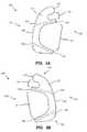
- FIG. 1is an isometric view of a bone implant
- FIG. 2Ais a top view of the bone implant of FIG. 1 ; and FIG. 2B is a bottom view of the bone implant of FIG. 1 ;
- FIG. 3Ais an isometric view of a proximal side of the bone implant of FIG. 1 ; and FIG. 3B is an isometric view of a distal side of the bone implant of FIG. 1 ;
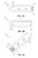
- FIG. 4Ais an isometric view of a bone anchor
- FIG. 4Bis a side view of the bone anchor of FIG. 4A ;
- FIG. 5Ais a top view of the bone anchor of FIG. 4A ;
- FIG. 5Bis a bottom view of the bone anchor of FIG. 4A ;
- FIG. 5Cis an isometric view of the bone anchor of FIG. 4A ;
- FIG. 6is an isometric view of a bone implant system including the bone implant of FIG. 1 and the bone anchor of FIG. 4A ;
- FIG. 7is an isometric view of the bone implant system of FIG. 6 implanted within a wedge osteotomy formed in a tibial bone;
- FIG. 8is an isometric view of another bone implant
- FIG. 9Ais a top view of the bone implant of FIG. 8 ; and FIG. 9B is a bottom view of the bone implant of FIG. 8 ;
- FIG. 10Ais an isometric view of a proximal side of the bone implant of FIG. 8 ;
- FIG. 10Bis an isometric view of a distal side of the bone implant of FIG. 8 ;
- FIG. 10Cis a side view of the distal side of the bone implant of FIG. 8 ;
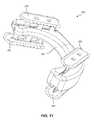
- FIG. 11is an isometric view of another bone implant system including the bone implant of FIG. 8 and the bone anchor of FIG. 4A ;
- FIG. 12is an isometric view of the bone implant system of FIG. 11 implanted within a wedge osteotomy formed in a calcaneus bone.
- phrases “connected to,” “coupled to” and “in communication with”refer to any form of interaction between two or more entities, including mechanical, electrical, magnetic, electromagnetic, fluid, and thermal interaction. Two components may be functionally coupled to each other even though they are not in direct contact with each other.
- the term “abutting”refers to items that are in direct physical contact with each other, although the items may not necessarily be attached together.
- the phrase “fluid communication”refers to two features that are connected such that a fluid within one feature is able to pass into the other feature.
- a sagittal planedivides a body into right and left portions.
- a midsagittal planedivides the body into bilaterally symmetric right and left halves.
- a coronal planedivides a body into anterior and posterior portions.
- a transverse planedivides a body into superior and inferior portions.
- Anteriormeans toward the front of the body.
- Posteriormeans toward the back of the body.
- Superiormeans toward the head.
- Inferiormeans toward the feet.
- Medialmeans toward the midline of the body.
- Lateralmeans away from the midline of the body.
- Axialmeans toward a central axis of the body.
- Abaxialaway from a central axis of the body.
- Ipsilateralmeans on the same side of the body. Contralateral means on the opposite side of the body.
- FIGS. 1-3Billustrate various views of a bone implant 100 .
- the bone implant 100may include a proximal side 101 , a distal side 102 , an upper side 103 , a lower side 104 , a first bone-contacting surface 111 , and a second bone-contacting surface 112 .
- the second bone-contacting surface 112may generally be opposite the first bone-contacting surface 111 .
- the first bone-contacting surface 111 and the second bone-contacting surface 112may be configured to diverge away from each other toward the proximal side 101 of the bone implant 100 and converge together toward the distal side 102 of the bone implant 100 .
- the first bone-contacting surface 111 and the second bone-contacting surface 112may be configured to diverge away from each other toward the distal side 102 of the bone implant 100 and converge together toward the proximal side 101 of the bone implant 100 .
- the first bone-contacting surface 111 and the second bone-contacting surface 112may be configured to diverge away from each other toward the lower side 104 of the bone implant 100 and converge together toward the upper side 103 of the bone implant 100 .
- the first bone-contacting surface 111 and the second bone-contacting surface 112may be configured to diverge away from each other toward the upper side 103 of the bone implant 100 and converge together toward the lower side 104 of the bone implant 100 .
- the bone implant 100may generally have a wedge shape that may be formed in one or more directions with a greater height toward one or more sides of the bone implant 100 , and a lesser height toward one or more other sides of the bone implant 100 .
- the bone implant 100may include a first protrusion 121 , a second protrusion 122 , a third protrusion 123 , and an intermediate portion 130 .
- the intermediate portion 130may be coupled to and intermediate the first protrusion 121 , the second protrusion 122 , and/or the third protrusion 123 .
- the intermediate portion 130may form the proximal side 101 of the bone implant 100 as shown, or another side.
- the third protrusion 123may be intermediate the first protrusion 121 and the second protrusion 122 .
- the first, second, and third protrusions 121 , 122 , 123may protrude away from the intermediate portion 130 toward the distal side 102 of the bone implant 100 as shown, or toward another side.
- the first protrusion 121 , the intermediate portion 130 , and the second protrusion 122may generally form an at least partially crescent shape, as can be seen in the top and bottom views of FIGS. 2A and 2B .
- the first protrusion 121 , the intermediate portion 130 , and the third protrusion 123may also generally form an at least partially crescent shape that may be contained within the at least partially crescent shape created by the first protrusion 121 , the intermediate portion 130 , and the second protrusion 122 .
- the second protrusion 122 , the intermediate portion 130 , and the third protrusion 123may also generally form an at least partially crescent shape that may be beside the shape created by the first protrusion 121 , the intermediate portion 130 , and the third protrusion 123 .
- the first, second, and third protrusions 121 , 122 , 123may be parallel or divergent to each other. Referring to FIGS. 2A and 2B , the first protrusion 121 is shown diverging from the second protrusion 122 toward the distal side 102 and converging toward the second protrusion 122 toward the proximal side 101 .
- the first protrusion 121is shown parallel, or nearly parallel, to the third protrusion 123 .
- the second protrusion 122is shown diverging from the third protrusion 123 toward the distal side 102 and converging toward the third protrusion 123 toward the proximal side 101 .
- the first protrusion 121 , the intermediate portion 130 , and the second protrusion 122may be designed or configured to rest against cortical bone or dense subcortical bone when the bone implant 100 is implanted.
- FIG. 7shows an arrangement in which the first protrusion 121 is against anterior cortical and/or subcortical bone near the tibial tuberosity, the intermediate portion 130 is against antero-medial cortical and/or subcortical bone, and the second protrusion 122 is against medial and/or postero-medial cortical and/or subcortical bone.
- the third protrusion 123may be designed or configured to rest against interior trabecular bone, preferably dense trabecular bone.
- FIG. 7shows the third protrusion 123 extending into an area of trabecular bone that is posterior to the tibial tuberosity and inferior to (distal to) the intercondyar eminence.
- the bone implant 100may include a first recess 141 that is formed intermediate the first protrusion 121 and the second protrusion 122 , and/or intermediate the third protrusion 123 and the second protrusion 122 as shown.
- the first recess 141may be substantially wider than the first, second, and/or third protrusions 121 , 122 , 123 .
- widthmay extend along a direction between the upper side 103 and the lower side 104 ; more generally, width may extend between the first and second protrusions 121 , 122 or parallel to the intermediate portion 130 .
- the width of the first recess 141may be more than twice the distal width of the first, second, and/or third protrusions 121 , 122 , 123 .
- the first recess 141may be more than half the overall width of the bone implant 100 .
- the bone implant 100may also include a second recess 142 that is formed intermediate the first protrusion 121 and the third protrusion 123 .
- the first recess 141may also be substantially wider than the second recess 142 , in other words, more than twice the distal width of the second recess 142 .
- the width of the second recess 142may be less than one and a half times the distal width of the first protrusion 121 .
- the first recess 141 and/or the second recess 142may be designed or configured to receive therapeutic material or agents, such as bone graft, preferably a block or wafer of bone graft.
- the bone implant 100may include a first channel 151 formed in the first bone-contacting surface 111 of the first protrusion 121 and/or the third protrusion 123 as shown.
- the first channel 151may extend along the first and/or third protrusion 121 , 123 and may extend through the proximal side 101 and the distal side 102 as shown.
- the first channel 151may be configured to receive a first bone anchor, which will be discussed in more detail below with reference to FIGS. 4A-5C .
- the bone implant 100may include a second channel 152 formed in the first bone-contacting surface 111 of the second protrusion 122 .
- the second channel 152may extend along the second protrusion 122 and may extend through the proximal side 101 and the distal side 102 as shown.
- the second channel 152may be configured to receive a second bone anchor.
- the bone implant 100may include a third channel 153 formed in the second bone-contacting surface 112 of the first protrusion 121 and/or the third protrusion 123 as shown.
- the third channel 153may extend along the first and/or third protrusion 121 , 123 and may extend through the proximal side 101 and the distal side 102 as shown.
- the third channel 153may be configured to receive a third bone anchor.
- the bone implant 100may include a fourth channel 154 formed in the second bone-contacting surface 112 of the second protrusion 122 .
- the fourth channel 154may extend along the second protrusion 122 and may extend through the proximal side 101 and the distal side 102 as shown.
- the fourth channel 154may be configured to receive a fourth bone anchor.
- the channels 151 , 152 , 153 , 154may generally converge toward each other similar to, or identical to, the convergence of the first and second bone-contacting surfaces 111 , 112 .
- the channels 151 , 152 , 153 , 154may be designed or configured to extend across regions of the bone-contacting surfaces 111 , 112 that are adjacent to areas of strong bone when the bone implant 100 is implanted, so that the corresponding bone anchors provide secure fixation when received in the channels and bone. This may influence the design or configuration of the protrusions 121 , 122 , and/or 123 .
- FIGS. 4A-5Cillustrate various views of a bone anchor 200 that may be used with the bone implants 100 , 500 .
- Bone implant 500will be discussed in more detail below with reference to FIGS. 8-10C .
- the bone anchor 200may include a rail 210 , a blade 230 , and at least one support 250 . Three supports are shown.
- the bone anchor 200may be elongated and have a generally H-shaped, or T-shaped, cross section.
- the rail 210may be configured to slidingly engage any of the channels of the bone implants 100 , 500 to couple the bone anchor 200 to the bone implants 100 , 500 .
- the rail 210may have a dovetail beam shape and may include one or more physical stop features 214 configured to prevent over insertion of the bone anchor 200 into the channel of the bone implant 100 , 500 .
- the rail 210may also include one or more tabs 212 that laterally protrude, or transversely project, from the rail 210 .
- the one or more tabs 212may also be referred to as laterally protruding tabs, lateral protrusions, and/or interference tabs.
- the one or more tabs 212may plastically deform when the rail 210 is inserted into a channel of the bone implants 100 , 500 .
- the one or more tabs 212may deform as the bone anchor 200 is driven into the channel, creating a line-to-line or interference fit between the rail 210 and the bone anchor 200 .
- This material deformationmay serve to reduce and/or eliminate any relative motion between the bone anchor 200 and the bone implant 100 , 500 .
- the deformationmay be characterized as plastic deformation, which may be at least partially irreversible. The deformation may cause galling, spot welding, and/or seizing to occur between the one or more tabs 212 and the channel. Any of these adhesive phenomena may serve to lock the bone anchor 200 to the implant 100 , 500 .
- one or more tabs 212may be located on each side of the rail 210 to provide greater fixation of the bone anchor 200 along the length of the channel. However, in other embodiments a single tab 212 , or no tab, may be located on one or more sides of the rail 210 .
- the rail 210 of the bone anchor 200may be inserted into a channel of the bone implants 100 , 500 such that when the rail 210 is inserted into the channel, the one or more tabs 212 may plastically deform, the at least one support 250 may protrude through a bone-contacting surface of the implant 100 , 500 , and the blade 230 may be carried at a distance from the bone-contacting surface of the implant 100 , 500 .
- the blade 230may be spaced apart from the rail 210 and configured to fix the bone anchor 200 to a bone.
- the blade 230may include a sharpened cutting edge 232 that penetrates the bone when the bone anchor 200 is urged against the bone in a first direction.
- the sharpened cutting edge 232may also include one or more serrations that resist removal of the bone anchor 200 from the bone when the bone anchor 200 is pulled from the bone in a second direction.
- the blade 230may be biased to diverge away from the rail 210 as the bone anchor 200 is urged against the bone.
- the biased blade 230may act to compress the bone against the bone implants 100 , 500 as the bone anchor 200 is advanced into the bone.
- the at least one support 250may connect the blade 230 to the rail 210 .
- the at least one support 250may also include a cutting edge 252 disposed on a leading end 202 of the bone anchor 200 and configured to cut through bone.
- FIG. 6illustrates a bone implant system 300 .
- the bone implant system 300may include the bone implant 100 of FIGS. 1-3B coupled to various bone anchors 200 , as described in FIGS. 4A-5C .
- the bone implant system 300may be implanted within a suitable wedge osteotomy to obtain a desired bone morphology.
- FIG. 7illustrates a corrected tibia 400 , where the bone implant system 300 has been implanted within a medial wedge osteotomy 420 formed in a tibial bone 410 .
- FIGS. 8-10Cillustrate various views of another bone implant 500 .
- the bone implant 500may include a proximal side 501 , a distal side 502 , an upper side 503 , a lower side 504 , a first bone-contacting surface 511 , and a second bone-contacting surface 512 .
- the second bone-contacting surface 512may generally be opposite the first bone-contacting surface 511 .
- the first bone-contacting surface 511 and the second bone-contacting surface 512may be configured to diverge away from each other toward the proximal side 501 of the bone implant 500 and converge together toward the distal side 502 of the bone implant 500 .
- the first bone-contacting surface 511 and the second bone-contacting surface 512may be configured to diverge away from each other toward the distal side 502 of the bone implant 500 and converge together toward the proximal side 501 of the bone implant 500 .
- the first bone-contacting surface 511 and the second bone-contacting surface 512may be configured to diverge away from each other toward the lower side 504 of the bone implant 500 and converge together toward the upper side 503 of the bone implant 500 .
- the first bone-contacting surface 511 and the second bone-contacting surface 512may be configured to diverge away from each other toward the upper side 503 of the bone implant 500 and converge together toward the lower side 504 of the bone implant 500 .
- the bone implant 500may generally have a wedge shape that may be formed in one or more directions with a greater height toward one or more sides of the bone implant 500 , and a lesser height toward one or more other sides of the bone implant 500 .
- the bone implant 500may include a first protrusion 521 , a second protrusion 522 , and an intermediate portion 530 .
- the intermediate portion 530may be coupled to and intermediate the first protrusion 521 and the second protrusion 522 .
- the intermediate portion 530may form the proximal side 501 of the bone implant 500 as shown, or another side.
- the first and second protrusions 521 , 522may protrude away from the intermediate portion 530 toward the distal side 502 of the bone implant 500 , or toward another side.
- the first protrusion 521 , the intermediate portion 530 , and the second protrusion 522may generally form an at least partially crescent shape, as can be seen in the top and bottom views of FIGS. 9A and 9B .
- the first and second protrusions 521 , 522may be parallel or divergent to each other. Referring to FIGS. 9A and 9B , the first protrusion 521 is shown diverging from the second protrusion 522 toward the distal side 502 and converging toward the second protrusion 522 toward the proximal side 501 .
- the first protrusion 521 , the intermediate portion 530 , and the second protrusion 522may be designed or configured to rest against cortical bone or dense subcortical bone when the bone implant 500 is implanted.
- FIG. 12shows an arrangement in which the first protrusion 521 is against anterior-inferior (anterior-plantar) cortical and/or subcortical calcaneal bone, the intermediate portion 530 is against lateral cortical and/or subcortical bone, and the second protrusion 522 is against posterior-superior cortical and/or subcortical bone.
- the bone implant 500may include a first recess 541 that is formed intermediate the first protrusion 521 and the second protrusion 522 .
- the first recess 541may be arcuate or another concave shape.
- the first recess 541may be substantially wider than the first and second protrusions 521 , 522 . Referring to FIG. 8 , width may extend along a direction between the upper side 503 and the lower side 504 ; more generally, width may extend between the first and second protrusions 521 , 522 or parallel to the intermediate portion 530 .
- the width of the first recess 541may be more than twice the distal width of the first or second protrusion 121 , 122 .
- the first recess 541may be more than half the overall width of the bone implant 500 .
- the first recess 541may be designed or configured to receive therapeutic material or agents, such as bone graft, preferably a block or wafer of bone graft.
- the bone implant 500may include a first channel 551 formed in the first bone-contacting surface 511 of the first protrusion 521 .
- the first channel 551may extend along the first protrusion 521 and may extend through the proximal side 501 and the distal side 502 as shown.
- the first channel 551may be configured to receive a first bone anchor 200 .
- the bone implant 500may include a second channel 552 formed in the first bone-contacting surface 511 of the second protrusion 522 .
- the second channel 552may extend along the second protrusion 522 and may extend through the proximal side 501 and the distal side 502 as shown.
- the second channel 552may be configured to receive a second bone anchor 200 .
- the bone implant 500may include a third channel 553 formed in the second bone-contacting surface 512 of the first protrusion 521 .
- the third channel 553may extend along the first protrusion 521 and may extend through the proximal side 501 and the distal side 502 as shown.
- the third channel 553may be configured to receive a third bone anchor 200 .
- the bone implant 500may include a fourth channel 554 formed in the second bone-contacting surface 512 of the second protrusion 522 .
- the fourth channel 554may extend along the second protrusion 522 and may extend through the proximal side 501 and the distal side 502 as shown.
- the fourth channel 554may be configured to receive a fourth bone anchor 200 .
- the channels 551 , 552 , 553 , 554may generally converge toward each other similar to, or identical to, the convergence of the first and second bone-contacting surfaces 511 , 512 .
- the channels 551 , 553may converge toward each other, and/or merge together, and/or intersect, before they reach the end of the first protrusion 521 , as may be seen in FIGS. 8, 9A, 9B, and 10C .
- convergence or intersection of the channels 551 , 553may result in a notch 560 formed in the material of the bone implant 500 between the channels 551 , 553 .
- convergence of channelsmay not result in a notch formed in the material of the bone implant between the converging channels.
- the channels 551 , 552 , 553 , 554may be designed or configured to extend across regions of the bone-contacting surfaces 511 , 512 that are adjacent to areas of strong bone when the bone implant 500 is implanted, so that the corresponding bone anchors provide secure fixation when received in the channels and bone. This may influence the design or configuration of the protrusions 521 , 522 .
- FIG. 11illustrates a bone implant system 600 .
- the bone implant system 600may include the bone implant 500 of FIGS. 8-10C coupled to various bone anchors 200 , as described in FIGS. 4A-5C .
- the bone implant system 600may be implanted within a suitable wedge osteotomy to obtain a desired bone morphology.
- FIG. 12illustrates a corrected calcaneus 700 , where the bone implant system 600 has been implanted within a wedge osteotomy 720 formed in a calcaneal bone 710 .
- the osteotomyextends from the posterior-superior aspect of the calcaneus 700 to the anterior-inferior aspect of the calcaneus.
- phrases “connected to,” “coupled to,” and “in communication with”refer to any form of interaction between two or more entities, including mechanical, electrical, magnetic, electromagnetic, fluid, and thermal interaction. Two components may be functionally coupled to each other even though they are not in direct contact with each other.
- the term “abutting”refers to items that are in direct physical contact with each other, although the items may not necessarily be attached together.
- the phrase “fluid communication”refers to two features that are connected such that a fluid within one feature is able to pass into the other feature.
- Any methods disclosed hereincomprise one or more steps or actions for performing the described method.
- the method steps and/or actionsmay be interchanged with one another.
- the order and/or use of specific steps and/or actionsmay be modified.
Landscapes
- Health & Medical Sciences (AREA)
- Orthopedic Medicine & Surgery (AREA)
- Life Sciences & Earth Sciences (AREA)
- Engineering & Computer Science (AREA)
- Animal Behavior & Ethology (AREA)
- General Health & Medical Sciences (AREA)
- Biomedical Technology (AREA)
- Heart & Thoracic Surgery (AREA)
- Veterinary Medicine (AREA)
- Public Health (AREA)
- Surgery (AREA)
- Cardiology (AREA)
- Oral & Maxillofacial Surgery (AREA)
- Vascular Medicine (AREA)
- Transplantation (AREA)
- Neurology (AREA)
- Nuclear Medicine, Radiotherapy & Molecular Imaging (AREA)
- Medical Informatics (AREA)
- Molecular Biology (AREA)
- Manufacturing & Machinery (AREA)
- Prostheses (AREA)
Abstract
Description
Claims (10)
Priority Applications (1)
| Application Number | Priority Date | Filing Date | Title |
|---|---|---|---|
| US15/713,594US10390955B2 (en) | 2016-09-22 | 2017-09-22 | Bone implants |
Applications Claiming Priority (2)
| Application Number | Priority Date | Filing Date | Title |
|---|---|---|---|
| US201662398259P | 2016-09-22 | 2016-09-22 | |
| US15/713,594US10390955B2 (en) | 2016-09-22 | 2017-09-22 | Bone implants |
Publications (2)
| Publication Number | Publication Date |
|---|---|
| US20180078374A1 US20180078374A1 (en) | 2018-03-22 |
| US10390955B2true US10390955B2 (en) | 2019-08-27 |
Family
ID=61617721
Family Applications (1)
| Application Number | Title | Priority Date | Filing Date |
|---|---|---|---|
| US15/713,594ActiveUS10390955B2 (en) | 2016-09-22 | 2017-09-22 | Bone implants |
Country Status (1)
| Country | Link |
|---|---|
| US (1) | US10390955B2 (en) |
Cited By (3)
| Publication number | Priority date | Publication date | Assignee | Title |
|---|---|---|---|---|
| US11369488B2 (en) | 2017-03-03 | 2022-06-28 | Engage Uni Llc | Unicompartmental knee arthroplasty |
| US11540928B2 (en) | 2017-03-03 | 2023-01-03 | Engage Uni Llc | Unicompartmental knee arthroplasty |
| EP4436499A4 (en)* | 2021-11-22 | 2025-09-17 | Uwe R Pontius | Orthopedic implant with mechanically interlocking subunits and associated procedures |
Families Citing this family (4)
| Publication number | Priority date | Publication date | Assignee | Title |
|---|---|---|---|---|
| EP2651341B1 (en) | 2010-12-16 | 2017-01-04 | Engage Medical Holdings, LLC | Arthroplasty systems and methods |
| CN112155803A (en)* | 2020-10-30 | 2021-01-01 | 嘉思特华剑医疗器材(天津)有限公司 | Biological adaptive gradient trabecular bone artificial knee joint tibial platform |
| US12433767B2 (en)* | 2021-04-02 | 2025-10-07 | Paragon 28, Inc. | Systems and methods for controlled facet repositioning in the calcaneus |
| WO2023215441A1 (en)* | 2022-05-06 | 2023-11-09 | Smith & Nephew, Inc. | Knee arthroplasty instruments and techniques |
Citations (299)
| Publication number | Priority date | Publication date | Assignee | Title |
|---|---|---|---|---|
| US3486505A (en) | 1967-05-22 | 1969-12-30 | Gordon M Morrison | Orthopedic surgical instrument |
| US3641590A (en) | 1970-01-16 | 1972-02-15 | Arthur A Michele | Acetabular replacement prosthesis and method of assembling |
| US3650309A (en) | 1969-02-12 | 1972-03-21 | Robert Neuschotz | Structure and use of fasteners having locking keys |
| US3842825A (en) | 1973-11-12 | 1974-10-22 | R Wagner | Hip fixation device |
| US3848276A (en) | 1973-05-03 | 1974-11-19 | Y Martinez | Knee implant device |
| US3882917A (en) | 1970-04-03 | 1975-05-13 | Litton Industrial Products | Self-locking thread |
| US3896504A (en) | 1972-10-14 | 1975-07-29 | Artur Fischer | Hip joint prosthesis |
| US3907017A (en) | 1974-09-30 | 1975-09-23 | Glenn W Stanwick | Interfering thread form |
| US3927503A (en) | 1973-12-26 | 1975-12-23 | Standard Pressed Steel Co | Prevailing torque fastener |
| US4011602A (en) | 1975-10-06 | 1977-03-15 | Battelle Memorial Institute | Porous expandable device for attachment to bone tissue |
| US4047524A (en) | 1975-04-28 | 1977-09-13 | Downs Surgical Limited | Surgical implant spinal staple |
| US4260005A (en) | 1977-11-09 | 1981-04-07 | Vsi Corporation | Self-locking fastener, fastener system, and process |
| US4349955A (en) | 1976-05-07 | 1982-09-21 | Taper Line, Inc. | Method of locking a male member to a female member |
| US4355429A (en) | 1979-01-26 | 1982-10-26 | Osteo Ag | Slide prosthesis for the knee joint |
| US4454875A (en) | 1982-04-15 | 1984-06-19 | Techmedica, Inc. | Osteal medical staple |
| US4484570A (en) | 1980-05-28 | 1984-11-27 | Synthes Ltd. | Device comprising an implant and screws for fastening said implant to a bone, and a device for connecting two separated pieces of bone |
| US4501269A (en) | 1981-12-11 | 1985-02-26 | Washington State University Research Foundation, Inc. | Process for fusing bone joints |
| USD281814S (en) | 1983-07-13 | 1985-12-17 | Techmedica, Inc. | Osteotomy staple |
| US4570623A (en) | 1983-06-02 | 1986-02-18 | Pfizer Hospital Products Group Inc. | Arched bridge staple |
| EP0179695A1 (en) | 1984-09-26 | 1986-04-30 | Pierre Kehr | Vertebral prosthesis, in particular for cervical vertebrae |
| US4611581A (en) | 1983-12-16 | 1986-09-16 | Acromed Corporation | Apparatus for straightening spinal columns |
| US4642869A (en) | 1984-02-07 | 1987-02-17 | Multifastener Corporation | Process of attaching a nut to a plate-shaped workpiece |
| US4681589A (en) | 1984-06-01 | 1987-07-21 | Tronzo Raymond G | Adjustable acetabular cup prosthesis as part of a total cup replacement system |
| US4716893A (en) | 1985-03-11 | 1988-01-05 | Artur Fischer | Bone fastener |
| US4743256A (en) | 1985-10-04 | 1988-05-10 | Brantigan John W | Surgical prosthetic implant facilitating vertebral interbody fusion and method |
| US4764067A (en) | 1985-11-22 | 1988-08-16 | Jsm Screw Co., Ltd. | Screw with groove for self-lock and method and rolling flat die for manufacturing the same |
| US4820305A (en) | 1986-11-03 | 1989-04-11 | Harms Juergen | Place holder, in particular for a vertebra body |
| US4834757A (en) | 1987-01-22 | 1989-05-30 | Brantigan John W | Prosthetic implant |
| US4838891A (en) | 1984-11-28 | 1989-06-13 | Branemark Per Ingvar | Joint prothesis |
| US4848328A (en) | 1986-05-20 | 1989-07-18 | Laboureau Jacques P | Agraffe for osteosynthesis |
| US4865607A (en) | 1985-10-02 | 1989-09-12 | Ulrich Witzel | Tibial plate for a knee-joint endoprosthesis |
| US4874389A (en) | 1987-12-07 | 1989-10-17 | Downey Ernest L | Replacement disc |
| US4930962A (en) | 1988-12-01 | 1990-06-05 | Pac-Fasteners, An Affiliate Of Peterson American Corp. | Nut and stud assembly |
| US4946378A (en) | 1987-11-24 | 1990-08-07 | Asahi Kogaku Kogyo Kabushiki Kaisha | Artificial intervertebral disc |
| US4957496A (en) | 1988-11-11 | 1990-09-18 | Mecron Medizinische Produkte Gmbh | Slotted slide plate assembly for osteosynthesis |
| US5002576A (en) | 1988-06-06 | 1991-03-26 | Mecron Medizinische Produkte Gmbh | Intervertebral disk endoprosthesis |
| US5019103A (en) | 1990-02-05 | 1991-05-28 | Boehringer Mannheim Corporation | Tibial wedge system |
| US5053038A (en) | 1989-08-17 | 1991-10-01 | Tenstaple, Inc. | Compression bone staple |
| US5074880A (en) | 1988-12-20 | 1991-12-24 | S.P.O.R.T. | Anchoring device for knee prosthesis |
| US5147361A (en) | 1989-11-29 | 1992-09-15 | Asahi Kogaku Kogyo Kabushiki Kaisha | Vertebral connecting plate |
| US5163960A (en) | 1990-06-28 | 1992-11-17 | Bonutti Peter M | Surgical devices assembled using heat bondable materials |
| US5192327A (en) | 1991-03-22 | 1993-03-09 | Brantigan John W | Surgical prosthetic implant for vertebrae |
| US5192324A (en) | 1982-02-18 | 1993-03-09 | Howmedica Inc. | Bone prosthesis with porous coating |
| WO1993022990A1 (en) | 1992-05-18 | 1993-11-25 | Astra Aktiebolag | Joint prosthesis and apparatus for preparing the bone prior to fitting of the prosthesis |
| US5306309A (en) | 1992-05-04 | 1994-04-26 | Calcitek, Inc. | Spinal disk implant and implantation kit |
| US5314477A (en) | 1990-03-07 | 1994-05-24 | J.B.S. Limited Company | Prosthesis for intervertebral discs and instruments for implanting it |
| US5352229A (en) | 1993-05-12 | 1994-10-04 | Marlowe Goble E | Arbor press staple and washer and method for its use |
| US5366479A (en) | 1991-10-18 | 1994-11-22 | United States Surgical Corporation | Surgical staple for attaching an object to body tissue |
| US5431658A (en) | 1994-02-14 | 1995-07-11 | Moskovich; Ronald | Facilitator for vertebrae grafts and prostheses |
| US5443515A (en) | 1994-01-26 | 1995-08-22 | Implex Corporation | Vertebral body prosthetic implant with slidably positionable stabilizing member |
| US5449359A (en) | 1991-09-05 | 1995-09-12 | Groiso; Jorge A. | Elastic clip for osteosynthesis |
| US5454814A (en) | 1992-09-02 | 1995-10-03 | Orthomed Sarl | Surgical clamp and clamp driving device |
| USD364462S (en) | 1994-03-28 | 1995-11-21 | Michelson Gary K | Spinal fixation staple |
| US5507816A (en) | 1991-12-04 | 1996-04-16 | Customflex Limited | Spinal vertebrae implants |
| US5514180A (en) | 1994-01-14 | 1996-05-07 | Heggeness; Michael H. | Prosthetic intervertebral devices |
| US5609635A (en) | 1988-06-28 | 1997-03-11 | Michelson; Gary K. | Lordotic interbody spinal fusion implants |
| USD378409S (en) | 1995-10-30 | 1997-03-11 | Michelson Gary K | Spinal fixation staple |
| US5658337A (en) | 1994-05-23 | 1997-08-19 | Spine-Tech, Inc. | Intervertebral fusion implant |
| US5683394A (en) | 1995-09-29 | 1997-11-04 | Advanced Spine Fixation Systems, Inc. | Fusion mass constrainer |
| US5702449A (en) | 1995-06-07 | 1997-12-30 | Danek Medical, Inc. | Reinforced porous spinal implants |
| US5709683A (en) | 1995-12-19 | 1998-01-20 | Spine-Tech, Inc. | Interbody bone implant having conjoining stabilization features for bony fusion |
| US5713899A (en) | 1995-04-27 | 1998-02-03 | Societe Jbs Sa | Cervical cage designed for the performance of intersomatic arthrodesis |
| US5769852A (en) | 1993-04-27 | 1998-06-23 | Medevelop Ab | Implantable anchoring element and anchoring assembly for prostheses |
| US5772661A (en) | 1988-06-13 | 1998-06-30 | Michelson; Gary Karlin | Methods and instrumentation for the surgical correction of human thoracic and lumbar spinal disease from the antero-lateral aspect of the spine |
| US5776202A (en) | 1993-09-07 | 1998-07-07 | Copf; Franz | Joint prosthesis |
| US5776199A (en) | 1988-06-28 | 1998-07-07 | Sofamor Danek Properties | Artificial spinal fusion implants |
| US5788701A (en) | 1995-12-21 | 1998-08-04 | Johnson & Johnson Professional, Inc. | Instrument system for knee prothesis implantation with universal handle or slap hammer |
| US5800550A (en) | 1996-03-13 | 1998-09-01 | Sertich; Mario M. | Interbody fusion cage |
| US5860973A (en) | 1995-02-27 | 1999-01-19 | Michelson; Gary Karlin | Translateral spinal implant |
| US5893890A (en) | 1994-03-18 | 1999-04-13 | Perumala Corporation | Rotating, locking intervertebral disk stabilizer and applicator |
| US5893889A (en) | 1997-06-20 | 1999-04-13 | Harrington; Michael | Artificial disc |
| US5947999A (en) | 1996-12-03 | 1999-09-07 | Groiso; Jorge A. | Surgical clip and method |
| US6039762A (en) | 1995-06-07 | 2000-03-21 | Sdgi Holdings, Inc. | Reinforced bone graft substitutes |
| US6059787A (en) | 1999-04-26 | 2000-05-09 | Allen; Drew | Compression bone staple apparatus and method |
| WO2000025707A1 (en) | 1998-10-30 | 2000-05-11 | Michelson Gary K | Self-broaching, rotatable, push-in interbody fusion implant and method for deployment thereof |
| US6063121A (en) | 1998-07-29 | 2000-05-16 | Xavier; Ravi | Vertebral body prosthesis |
| US6080155A (en) | 1988-06-13 | 2000-06-27 | Michelson; Gary Karlin | Method of inserting and preloading spinal implants |
| US6096080A (en) | 1998-05-06 | 2000-08-01 | Cortek, Inc. | Apparatus for spinal fusion using implanted devices |
| US6102949A (en) | 1997-12-03 | 2000-08-15 | Biedermann Motech Gmbh | Intervertebrae implant |
| US6113638A (en) | 1999-02-26 | 2000-09-05 | Williams; Lytton A. | Method and apparatus for intervertebral implant anchorage |
| US6120503A (en) | 1994-03-28 | 2000-09-19 | Michelson; Gary Karlin | Apparatus instrumentation, and method for spinal fixation |
| WO2000064360A2 (en) | 1999-04-23 | 2000-11-02 | Sdgi Holdings, Inc. | Method for the correction of spinal deformities through vertebral body tethering without fusion |
| US6159214A (en) | 1996-07-31 | 2000-12-12 | Michelson; Gary K. | Milling instrumentation and method for preparing a space between adjacent vertebral bodies |
| WO2001003570A2 (en) | 1999-07-07 | 2001-01-18 | Wall M D Eric J | Spinal correction system |
| US6224607B1 (en) | 1999-01-25 | 2001-05-01 | Gary K. Michelson | Instrumentation and method for creating an intervertebral space for receiving an implant |
| US6235059B1 (en) | 1996-04-03 | 2001-05-22 | Scient'x (Societe A Responsabilite Limitee) | Intersomatic setting and fusion system |
| US6241770B1 (en) | 1999-03-05 | 2001-06-05 | Gary K. Michelson | Interbody spinal fusion implant having an anatomically conformed trailing end |
| US6309421B1 (en) | 1994-03-18 | 2001-10-30 | Madhavan Pisharodi | Rotating, locking intervertebral disk stabilizer and applicator |
| US20010037154A1 (en) | 2000-04-10 | 2001-11-01 | Martin Christopher Harris | Modular radial head prostheses |
| US20010047208A1 (en) | 1999-12-08 | 2001-11-29 | Michelson Gary K. | Spinal implant surface configuration |
| US6325805B1 (en) | 1999-04-23 | 2001-12-04 | Sdgi Holdings, Inc. | Shape memory alloy staple |
| US6336928B1 (en) | 1996-10-18 | 2002-01-08 | Depuy France | Device for securing at least two vertebrae |
| US20020004683A1 (en) | 2000-07-10 | 2002-01-10 | Michelson Gary K. | Flanged interbody spinal fusion implants |
| US20020035400A1 (en) | 2000-08-08 | 2002-03-21 | Vincent Bryan | Implantable joint prosthesis |
| US20020049447A1 (en) | 2000-08-29 | 2002-04-25 | Li Medical Technologies, Inc. | Expandable surgical fastener and method |
| US6402785B1 (en) | 1999-06-04 | 2002-06-11 | Sdgi Holdings, Inc. | Artificial disc implant |
| US6413278B1 (en) | 1998-03-30 | 2002-07-02 | J. Alexander Marchosky | Prosthetic system |
| US20020099376A1 (en) | 2001-01-23 | 2002-07-25 | Michelson Gary K. | Interbody spinal implant with trailing end adapted to receive bone screws |
| US6432107B1 (en) | 2000-01-15 | 2002-08-13 | Bret A. Ferree | Enhanced surface area spinal fusion devices |
| US6436098B1 (en) | 1993-06-10 | 2002-08-20 | Sofamor Danek Holdings, Inc. | Method for inserting spinal implants and for securing a guard to the spine |
| US20020116065A1 (en) | 1998-10-21 | 2002-08-22 | Jackson Roger P. | Spinal fusion apparatus and method |
| US20020116165A1 (en) | 2001-02-13 | 2002-08-22 | El-Ghoroury Hussein S. | Matched instruction set processor systems and method, system, and apparatus to efficiently design and implement matched instruction set processor systems by mapping system designs to re-configurable hardware platforms |
| US6447524B1 (en) | 2000-10-19 | 2002-09-10 | Ethicon Endo-Surgery, Inc. | Fastener for hernia mesh fixation |
| US6447546B1 (en) | 2000-08-11 | 2002-09-10 | Dale G. Bramlet | Apparatus and method for fusing opposing spinal vertebrae |
| US6458159B1 (en) | 2000-08-15 | 2002-10-01 | John S. Thalgott | Disc prosthesis |
| US20020147454A1 (en) | 2001-04-10 | 2002-10-10 | Neto Aziz Rassi | Building configuration introduced in a surgical-use screw |
| US20020147499A1 (en) | 2001-02-26 | 2002-10-10 | Shea Jeffrey J. | Locking systems for implants |
| US20020161443A1 (en) | 2001-04-02 | 2002-10-31 | Michelson Gary K. | Artificial contoured spinal fusion implants made of a material other than bone |
| US20020165613A1 (en) | 2001-05-04 | 2002-11-07 | Chih-I Lin | Intervertebral fixation device having one or more bracing elements |
| US6478800B1 (en) | 2000-05-08 | 2002-11-12 | Depuy Acromed, Inc. | Medical installation tool |
| US6485517B1 (en) | 1999-05-05 | 2002-11-26 | Gary K. Michelson | Nested interbody spinal fusion implants |
| US6506216B1 (en) | 1998-05-13 | 2003-01-14 | Depuy Products, Inc. | Tibial tray with adjustable keel |
| WO2003005939A2 (en) | 2001-07-13 | 2003-01-23 | Ldr Medical | Vertebral cage device with modular fixation |
| US20030045940A1 (en) | 2001-08-24 | 2003-03-06 | Robert Eberlein | Artificial intervertebral disc |
| US20030060884A1 (en) | 1999-05-10 | 2003-03-27 | Fell Barry M. | Surgically implantable knee prosthesis having keels |
| US6558423B1 (en) | 1999-05-05 | 2003-05-06 | Gary K. Michelson | Interbody spinal fusion implants with multi-lock for locking opposed screws |
| US6558424B2 (en) | 2001-06-28 | 2003-05-06 | Depuy Acromed | Modular anatomic fusion device |
| WO2003039400A2 (en) | 2001-11-06 | 2003-05-15 | Ldr Medical | Osseous anchoring device for a prosthesis |
| US6582468B1 (en) | 1998-12-11 | 2003-06-24 | Spryker Spine | Intervertebral disc prosthesis with compressible body |
| US20030120344A1 (en) | 2001-04-02 | 2003-06-26 | Michelson Gary K. | Contoured spinal fusion implants made of bone or a bone composite material |
| WO2003053290A1 (en) | 2001-12-12 | 2003-07-03 | Vita Special Purpose Corporation | Bioactive spinal implants and method of manufacture thereof |
| EP1327423A1 (en) | 2002-01-11 | 2003-07-16 | Centerpulse Orthopedics Ltd. | A surgically implantable knee prosthesis having keels |
| US6599294B2 (en) | 1999-01-30 | 2003-07-29 | Aesculap Ag & Co. Kg | Surgical instrument for introducing intervertebral implants |
| WO2003065930A2 (en) | 2002-02-02 | 2003-08-14 | Gary K Michelson | Spinal fusion implant having deployable bone engaging projections |
| US20030158553A1 (en) | 1988-06-13 | 2003-08-21 | Michelson Gary Karlin | Instrumentation for the surgical correction of spinal disease |
| US6610093B1 (en) | 2000-07-28 | 2003-08-26 | Perumala Corporation | Method and apparatus for stabilizing adjacent vertebrae |
| US6620198B2 (en) | 1999-10-07 | 2003-09-16 | Exactech, Inc. | Composite bearing inserts for total knee joints |
| US20030195632A1 (en) | 2001-02-06 | 2003-10-16 | Foley Kevin T. | Spinal implant with attached ligament |
| US20030195561A1 (en) | 2000-12-07 | 2003-10-16 | Carley Michael T. | Closure device and methods for making and using them |
| WO2003092507A2 (en) | 2002-05-06 | 2003-11-13 | Sdgi Holdings, Inc. | Instrumentation and methods for preparation of an intervertebral space |
| US6652533B2 (en) | 2001-09-20 | 2003-11-25 | Depuy Acromed, Inc. | Medical inserter tool with slaphammer |
| US20040030339A1 (en) | 2001-04-20 | 2004-02-12 | Wack Michael A. | Dual locking plate and associated method |
| US20040030336A1 (en) | 2002-08-06 | 2004-02-12 | Khanna Rohit Kumar | Anterior cervical spine stabilization method and system |
| US6716245B2 (en) | 2000-07-12 | 2004-04-06 | Spine Next | Intersomatic implant |
| US20040073315A1 (en) | 2002-04-25 | 2004-04-15 | Justin Daniel F. | Modular bone implant, tools, and method |
| US6726720B2 (en) | 2002-03-27 | 2004-04-27 | Depuy Spine, Inc. | Modular disc prosthesis |
| US20040083005A1 (en) | 1998-12-22 | 2004-04-29 | Magnus Jacobsson | Method of anchoring a prosthesis structure |
| US6740118B2 (en) | 2002-01-09 | 2004-05-25 | Sdgi Holdings, Inc. | Intervertebral prosthetic joint |
| US6743256B2 (en) | 2000-10-11 | 2004-06-01 | Michael D. Mason | Graftless spinal fusion device |
| US20040122518A1 (en) | 2002-12-19 | 2004-06-24 | Rhoda William S. | Intervertebral implant |
| US20040133203A1 (en) | 2002-10-28 | 2004-07-08 | Young J Stewart | Multi-axial, cross-link connector system for spinal implants |
| US6767356B2 (en) | 2000-09-01 | 2004-07-27 | Angiolink Corporation | Advanced wound site management systems and methods |
| US20040148028A1 (en) | 2002-12-19 | 2004-07-29 | Ferree Bret A. | Artificial disc replacement (ADR) extraction methods and apparatus |
| US6770096B2 (en) | 1999-07-01 | 2004-08-03 | Spinevision S.A. | Interbody spinal stabilization cage and spinal stabilization method |
| US6770074B2 (en) | 1988-06-13 | 2004-08-03 | Gary Karlin Michelson | Apparatus for use in inserting spinal implants |
| WO2004071359A1 (en) | 2003-02-12 | 2004-08-26 | Sdgi Holdings Inc. | Articular disc prosthesis for lateral insertion |
| US20040176853A1 (en) | 2003-03-05 | 2004-09-09 | Sennett Andrew R. | Apparatus and method for spinal fusion using posteriorly implanted devices |
| US6800093B2 (en) | 1998-05-06 | 2004-10-05 | Cortek, Inc. | Device for spinal fusion |
| US6802863B2 (en) | 2002-03-13 | 2004-10-12 | Cross Medical Products, Inc. | Keeled prosthetic nucleus |
| WO2004089240A2 (en) | 2003-04-04 | 2004-10-21 | Theken Disc, Llc | Artificial disc prosthesis |
| US20040225295A1 (en) | 2001-07-16 | 2004-11-11 | Rafail Zubok | Wedge ramp distractor and related methods for use in implanting artificial intervertebral discs |
| WO2004108015A2 (en) | 2003-06-06 | 2004-12-16 | Ferree Bret A | Artificial disc replacements with oblique keels |
| US20040254644A1 (en) | 2002-10-21 | 2004-12-16 | Taylor Brett Allison | Intervertebral disk prosthesis |
| US20040254581A1 (en) | 2003-02-04 | 2004-12-16 | Leclair Walter J. | Furcated bone screw |
| US20040260286A1 (en) | 1999-10-08 | 2004-12-23 | Ferree Bret A. | Intradiscal devices with anti-extrusion keels |
| US6835208B2 (en) | 1998-03-30 | 2004-12-28 | J. Alexander Marchosky | Prosthetic system |
| US20050004672A1 (en) | 1995-10-16 | 2005-01-06 | John Pafford | Bone grafts |
| US20050014919A1 (en) | 2001-06-15 | 2005-01-20 | Hyoe Hatakeyama | Lignin-based polyurethane and process for producing the same |
| US6849093B2 (en) | 2001-03-09 | 2005-02-01 | Gary K. Michelson | Expansion constraining member adapted for use with an expandable interbody spinal fusion implant and method for use thereof |
| US20050027300A1 (en) | 2003-03-31 | 2005-02-03 | Depuy Spine, Inc. | Method and apparatus for artificial disc insertion |
| US20050049600A1 (en) | 2003-08-05 | 2005-03-03 | Groiso Jorge A. | Osteosynthesis clip and insertion tool for inserting an osteosynthesis clip into bone tissue fragments |
| US20050055031A1 (en) | 2003-09-10 | 2005-03-10 | Roy Lim | Devices and methods for inserting spinal implants |
| US20050125065A1 (en) | 2003-11-05 | 2005-06-09 | St. Francis Medical Technologies Inc. | Laterally insertable artificial vertebral disk replacement implant with crossbar spacer |
| WO2005051243A2 (en) | 2003-10-30 | 2005-06-09 | Steven Streatfield Gill | An intervertebral prosthesis |
| US20050131545A1 (en) | 2003-12-10 | 2005-06-16 | Alan Chervitz | Spinal facet implant with spherical implant apposition surface and bone bed and methods of use |
| US20050149192A1 (en) | 2003-11-20 | 2005-07-07 | St. Francis Medical Technologies, Inc. | Intervertebral body fusion cage with keels and implantation method |
| US20050165408A1 (en) | 2004-01-26 | 2005-07-28 | Puno Rolando M. | Methods and instrumentation for inserting intervertebral grafts and devices |
| US6923810B1 (en) | 1988-06-13 | 2005-08-02 | Gary Karlin Michelson | Frusto-conical interbody spinal fusion implants |
| US20050171606A1 (en) | 2000-06-13 | 2005-08-04 | Michelson Gary K. | Method for installation of manufactured implants shaped to conform to a prepared implantation space |
| US6926718B1 (en) | 1997-02-11 | 2005-08-09 | Gary K. Michelson | Multilock anterior cervical plating system |
| US20050177239A1 (en) | 1995-09-04 | 2005-08-11 | Amiram Steinberg | Method and apparatus for computerized surgery |
| WO2005074841A1 (en) | 2004-01-30 | 2005-08-18 | Sdgi Holdings, Inc. | Anatomic implants designed to minimize instruments and surgical techniques |
| US20050192586A1 (en) | 2002-10-29 | 2005-09-01 | St. Francis Medical Technologies, Inc. | Method of preparing for an artificial intervertebral implant using tool |
| US6942698B1 (en) | 2004-04-23 | 2005-09-13 | Roger P. Jackson | Spinal fusion interbody spacer |
| US20050234555A1 (en) | 2004-04-16 | 2005-10-20 | Depuy Spine, Inc. | Intervertebral disc with monitoring and adjusting capabilities |
| US6972035B2 (en) | 2000-04-19 | 2005-12-06 | Michelson Gary K | Expandable threaded arcuate interbody spinal fusion implant with cylindrical configuration during insertion |
| US20060004453A1 (en) | 2004-06-30 | 2006-01-05 | Depuy Spine, Inc. | Ceramic disc prosthesis |
| US6989031B2 (en) | 2001-04-02 | 2006-01-24 | Sdgi Holdings, Inc. | Hemi-interbody spinal implant manufactured from a major long bone ring or a bone composite |
| US20060058802A1 (en) | 2004-09-06 | 2006-03-16 | Hakon Kofoed | Fixation implant for a bone graft within a joint for the purpose of ensuring arthrodesis of the joint |
| US20060074421A1 (en) | 2003-05-08 | 2006-04-06 | Bickley Barry T | Fixation augmentation device and related techniques |
| US20060085071A1 (en) | 2003-02-06 | 2006-04-20 | Beat Lechmann | Intervertebral implant |
| US20060095136A1 (en) | 2004-11-03 | 2006-05-04 | Mcluen Design, Inc. | Bone fusion device |
| US7044972B2 (en) | 2001-01-30 | 2006-05-16 | Synthes Ag Chur | Bone implant, in particular, an inter-vertebral implant |
| WO2006051547A2 (en) | 2004-11-15 | 2006-05-18 | Disc-O-Tech Medical Technologies, Ltd. | Assembled prosthesis such as a disc |
| US20060111787A1 (en) | 2004-11-05 | 2006-05-25 | Bailie David S | Glenoid prosthesis and method of implanting same |
| US20060116769A1 (en) | 2004-11-26 | 2006-06-01 | Theirry Marnay | Intervertebral implant |
| US7056345B2 (en) | 2000-12-15 | 2006-06-06 | Spineology, Inc. | Annulus-reinforcing band |
| US7060097B2 (en) | 2003-03-31 | 2006-06-13 | Depuy Spine, Inc. | Method and apparatus for implant stability |
| US20060129238A1 (en) | 2004-10-26 | 2006-06-15 | Adam Paltzer | Spinal stabilization device and methods |
| WO2006074414A2 (en) | 2005-01-08 | 2006-07-13 | Alphaspine, Inc. | Modular disc device |
| US7087082B2 (en) | 1998-08-03 | 2006-08-08 | Synthes (Usa) | Bone implants with central chambers |
| US20060178745A1 (en) | 2005-02-10 | 2006-08-10 | Depuy Spine, Inc. | Intervertebral prosthetic disc |
| US20060195097A1 (en) | 2005-02-25 | 2006-08-31 | Evans David E | Implant insertion apparatus and method of use |
| US20060212123A1 (en) | 2003-07-22 | 2006-09-21 | Beat Lechmann | Articulated endoprosthesis |
| US7115146B2 (en) | 2000-03-22 | 2006-10-03 | Boyer Ii Michael L | Multipiece implants formed of bone material |
| US7118580B1 (en) | 1999-09-14 | 2006-10-10 | Spine Solutions Inc. | Instrument for inserting intervertebral implants |
| US20060241641A1 (en) | 2005-04-22 | 2006-10-26 | Sdgi Holdings, Inc. | Methods and instrumentation for distraction and insertion of implants in a spinal disc space |
| US7128761B2 (en) | 2003-12-10 | 2006-10-31 | Axiomed Spine Corporation | Method and apparatus for replacing a damaged spinal disc |
| WO2006120505A1 (en) | 2004-12-22 | 2006-11-16 | Ldr Medical | Intervertebral disc prosthesis |
| WO2006122194A1 (en) | 2005-05-11 | 2006-11-16 | Children's Hospital Medical Center | Spinal correction system |
| US20070010890A1 (en) | 2005-07-08 | 2007-01-11 | Howmedica Osteonics Corp. | Modular tibial baseplate |
| US7166110B2 (en) | 2004-01-09 | 2007-01-23 | Yundt Kent D | Method, system and apparatus for interbody fusion |
| US7169182B2 (en) | 2001-07-16 | 2007-01-30 | Spinecore, Inc. | Implanting an artificial intervertebral disc |
| US20070050032A1 (en) | 2005-09-01 | 2007-03-01 | Spinal Kinetics, Inc. | Prosthetic intervertebral discs |
| WO2007028098A2 (en) | 2005-09-01 | 2007-03-08 | Spinal Kinetics, Inc. | Prosthetic intervertebral discs |
| US20070073404A1 (en) | 2005-09-23 | 2007-03-29 | Ralph Rashbaum | Intervertebral disc prosthesis |
| US7204852B2 (en) | 2002-12-13 | 2007-04-17 | Spine Solutions, Inc. | Intervertebral implant, insertion tool and method of inserting same |
| US20070093839A1 (en) | 2005-09-12 | 2007-04-26 | Beckendorf Brandon G | Compression staple |
| US20070118132A1 (en) | 2002-07-19 | 2007-05-24 | Triage Medical, Inc. | Method and apparatus for spinal fixation |
| US20070123903A1 (en) | 2005-10-31 | 2007-05-31 | Depuy Spine, Inc. | Medical Device installation tool and methods of use |
| US20070142922A1 (en) | 2005-12-21 | 2007-06-21 | Lewis Paul P P | Modular hip cup assembly, fastener assembly & fastener |
| US7235105B2 (en) | 2003-09-18 | 2007-06-26 | Jackson Roger P | Threaded center line cage with winged end gap |
| US7235101B2 (en) | 2003-09-15 | 2007-06-26 | Warsaw Orthopedic, Inc. | Revisable prosthetic device |
| WO2007087366A2 (en) | 2006-01-25 | 2007-08-02 | Spinemedica Corporation | Spinal disc implants with flexible keels and methods of fabricating implants |
| US20070185375A1 (en) | 2006-02-06 | 2007-08-09 | Depuy Spine, Inc. | Medical device installation tool |
| US20070233244A1 (en) | 2006-03-28 | 2007-10-04 | Depuy Spine, Inc. | Artificial Disc Replacement Using Posterior Approach |
| US20070239278A1 (en) | 2006-04-06 | 2007-10-11 | Sdgi Holdings, Inc. | Intervertebral prosthetic devices and methods |
| US20070288005A1 (en) | 2006-04-05 | 2007-12-13 | Uri Arnin | Fixation of spinal prosthesis |
| US20070288021A1 (en) | 2006-06-07 | 2007-12-13 | Howmedica Osteonics Corp. | Flexible joint implant |
| US20070299529A1 (en) | 2006-06-22 | 2007-12-27 | Depuy Products, Inc. | Tibial insert having multiple keels |
| WO2008014258A2 (en) | 2006-07-24 | 2008-01-31 | Spine Solutions, Inc. | Intervertebral implant with keel |
| WO2008014453A2 (en) | 2006-07-28 | 2008-01-31 | Spinalmotion, Inc. | Spinal prosthesis with multiple pillar anchors |
| WO2008021955A2 (en) | 2006-08-10 | 2008-02-21 | James Dwyer | Modular intervertebral disc prosthesis and method of replacing an intervertebral disc |
| EP1897517A1 (en) | 2006-09-07 | 2008-03-12 | Biomet Manufacturing Corp. | Method and apparatus for wrist anthroplasty |
| WO2008034140A2 (en) | 2006-09-15 | 2008-03-20 | Pioneer Surgical Technology, Inc. | Systems and methods for sizing, inserting and securing an implant intervertebral space |
| US7357817B2 (en) | 2005-05-19 | 2008-04-15 | Howmedica Osteonics Corp. | Modular keel tibial component |
| US20080108997A1 (en) | 2006-09-12 | 2008-05-08 | Pioneer Surgical Technology, Inc. | Mounting Devices for Fixation Devices and Insertion Instruments Used Therewith |
| US20080132949A1 (en) | 2005-12-29 | 2008-06-05 | Joseph Aferzon | Apparatus and method for anterior intervertebral spinal fixation and fusion |
| US20080147203A1 (en) | 2006-12-15 | 2008-06-19 | Zimmer Technology, Inc. | Modular plate and keel provisionals |
| US20080154377A1 (en) | 2006-12-22 | 2008-06-26 | Voellmicke John C | Composite vertebral spacers and instrument |
| US20080167721A1 (en) | 2006-12-22 | 2008-07-10 | Qi-Bin Bao | Implant retention device and method |
| US20080177275A1 (en) | 2006-12-01 | 2008-07-24 | Charles Wing | Interbody distractor |
| US20080208345A1 (en) | 2005-10-27 | 2008-08-28 | Kinetic Spine Technologies, Inc. | Intervertebral implant |
| US20080249575A1 (en) | 2007-04-03 | 2008-10-09 | Warsaw Orthopedic, Inc. | Anchor Member Locking Features |
| US20080269764A1 (en) | 2007-04-25 | 2008-10-30 | Spinal Elements, Inc. | Spinal implant distractor/inserter |
| WO2008128367A1 (en) | 2007-04-20 | 2008-10-30 | Woodwelding Ag | Method for fastening an implant to bone tissue and corresponding implant system |
| US20080275455A1 (en) | 2006-08-16 | 2008-11-06 | Amicus, Llc | Apparatus and Methods for Inserting an Implant |
| US20080287957A1 (en) | 2007-05-18 | 2008-11-20 | Depuy Spine, Inc. | Insertion blade assembly and method of use |
| US20090005870A1 (en) | 2007-06-26 | 2009-01-01 | John Riley Hawkins | Highly Lordosed Fusion Cage |
| US20090005784A1 (en) | 2007-04-25 | 2009-01-01 | Spinal Elements, Inc. | Spinal implant distractor/inserter |
| US7481832B1 (en) | 2003-09-09 | 2009-01-27 | Biomet Sports Medicine, Llc | Method and apparatus for use of a self-tapping resorbable screw |
| USD586915S1 (en) | 2007-06-28 | 2009-02-17 | Biomedical Enterprises, Inc. | Soft tissue staple |
| US20090048604A1 (en) | 2007-08-13 | 2009-02-19 | Stryker Spine | Insertion instrument for intervertebral implants |
| US7503935B2 (en) | 2003-12-02 | 2009-03-17 | Kyphon Sarl | Method of laterally inserting an artificial vertebral disk replacement with translating pivot point |
| US20090088849A1 (en) | 2007-09-27 | 2009-04-02 | Warsaw Orthopedic, Inc. | Intervertebral Implant |
| US20090099602A1 (en) | 2007-09-11 | 2009-04-16 | Kamran Aflatoon | Method of lateral facet approach, decompression and fusion using screws and staples as well as arthroplasty |
| US20090099601A1 (en) | 2007-10-11 | 2009-04-16 | International Spinal Innovations, Llc | Minimally invasive lateral intervertbral fixation system, device and method |
| WO2009070721A1 (en) | 2007-11-28 | 2009-06-04 | Pioneer Surgical Technology, Inc | Device for securing an implant to tissue |
| USD594986S1 (en) | 2005-03-29 | 2009-06-23 | Nuvasive, Inc. | Intervertebral implant |
| US7556650B2 (en) | 2004-06-29 | 2009-07-07 | Spine Wave, Inc. | Methods for injecting a curable biomaterial into an intervertebral space |
| US7572293B2 (en) | 2005-06-30 | 2009-08-11 | Depuy Products, Inc. | Tibial insert and associated surgical method |
| US20090240333A1 (en) | 2007-09-17 | 2009-09-24 | Trudeau Jeffrey L | Motion Preserving Artificial Intervertebral Disc Device |
| US7611538B2 (en) | 2003-08-04 | 2009-11-03 | Zimmer Spine S.A.S. | Intervertebral disk prosthesis |
| US20100004747A1 (en) | 2008-07-07 | 2010-01-07 | Jin-Fu Lin | Trans-Vertebral and Intra-Vertebral Plate and Fusion Cage Device for Spinal Interbody Fusion and Method of Operation |
| US7658766B2 (en) | 2006-05-01 | 2010-02-09 | Warsaw Orthopedic, Inc. | Intervertebral implants with covered inner chamber and methods of use |
| US20100069958A1 (en) | 2008-09-18 | 2010-03-18 | Smith & Nephew, Inc. | Tenodesis Implant |
| WO2010039026A1 (en) | 2008-09-30 | 2010-04-08 | J. Van Straten Beheer B.V. | Ankle prosthesis and a tibial component therefor |
| US7749271B2 (en) | 2005-11-24 | 2010-07-06 | Aesculap Ag & Co Kg | Surgical guiding instrument |
| US20100185287A1 (en) | 2009-01-21 | 2010-07-22 | Warsaw Orthopedic, Inc. | Spinal nucleus replacement implants |
| US20100201739A1 (en) | 2009-02-12 | 2010-08-12 | Sony Corporation | Liquid ejection apparatus |
| US20100204739A1 (en) | 2009-02-11 | 2010-08-12 | IMDS, Inc. | Intervertebral implant with integrated fixation |
| US7780676B2 (en) | 2006-07-11 | 2010-08-24 | Ebi, Llc | Intervertebral implantation apparatus |
| WO2010121002A1 (en) | 2009-04-15 | 2010-10-21 | Synthes Usa, Llc | Vertebral implant system for a flexible interbody spacer |
| US7837732B2 (en) | 2003-11-20 | 2010-11-23 | Warsaw Orthopedic, Inc. | Intervertebral body fusion cage with keels and implantation methods |
| US7850791B2 (en) | 2004-01-21 | 2010-12-14 | Forschungszentrum Julich Gmbh | Protective layer for an aluminum-containing alloy for high-temperature use |
| US7883510B2 (en) | 2004-08-27 | 2011-02-08 | Depuy Spine, Inc. | Vertebral staples and insertion tools |
| US7887563B2 (en) | 2001-06-07 | 2011-02-15 | Abbott Vascular Inc. | Surgical staple |
| US7909871B2 (en) | 2005-10-03 | 2011-03-22 | Samy Abdou | Devices and methods for inter-vertebral orthopedic device placement |
| US7918891B1 (en) | 2004-03-29 | 2011-04-05 | Nuvasive Inc. | Systems and methods for spinal fusion |
| WO2011044879A1 (en) | 2009-10-12 | 2011-04-21 | Aap Implantate Ag | Modular system for anchoring and positioning components of implants |
| US7966799B2 (en) | 2006-09-29 | 2011-06-28 | Ethicon Endo-Surgery, Inc. | Method of manufacturing staples |
| US20110160766A1 (en) | 2005-11-02 | 2011-06-30 | Hendren Ronald D | Medical Affixation Device |
| US20110160866A1 (en) | 2008-09-02 | 2011-06-30 | Synthes Usa, Llc | Intervertebral implant with blades for connecting to adjacent vertebral bodies |
| US20110166608A1 (en) | 2009-07-14 | 2011-07-07 | Neil Duggal | Joint Arthrodesis and Arthroplasty |
| WO2011090508A1 (en) | 2010-01-22 | 2011-07-28 | Stephen Hochschuler | Apparatus and method for stabilizing adjacent bone portions |
| US8034076B2 (en) | 2000-10-23 | 2011-10-11 | Tyco Healthcare Group Lp | Absorbable fastener and applying apparatus |
| US8062297B2 (en) | 2008-07-24 | 2011-11-22 | Biopro, Inc. | Bone fixation apparatus and method of manufacture |
| US8100974B2 (en) | 2004-06-30 | 2012-01-24 | Synergy Disc Replacement, Inc. | Artificial spinal disc |
| US8100972B1 (en) | 2007-07-02 | 2012-01-24 | Theken Spine, Llc | Spinal cage having deployable member |
| US8105389B2 (en) | 2002-10-24 | 2012-01-31 | Biomet Manufacturing Corp. | Method and apparatus for wrist arthroplasty |
| US8123757B2 (en) | 2003-12-31 | 2012-02-28 | Depuy Spine, Inc. | Inserter instrument and implant clip |
| US8133283B2 (en) | 2007-06-06 | 2012-03-13 | Kenneth Mitchell Wilson | Scapho-lunate fixation implants and methods of use |
| US8157865B2 (en) | 2009-01-22 | 2012-04-17 | Stephen Hochschuler | Apparatus and method for stabilizing adjacent bone portions |
| WO2012083205A1 (en) | 2010-12-16 | 2012-06-21 | Medicinelodge, Inc. Dba Imds Co-Innovation | Arthroplasty systems and methods |
| US20120215315A1 (en) | 2010-01-22 | 2012-08-23 | Stephen Hochschuler | Apparatus and method for stabilizing adjacent bone portions |
| WO2012112598A1 (en) | 2011-02-14 | 2012-08-23 | Imds Corporation | System and method for bone anchor removal |
| US20120253406A1 (en) | 2009-11-03 | 2012-10-04 | Howmedica Osteonics Corp. | Intervertebral implant with integrated fixation |
| US20120265259A1 (en) | 2011-04-15 | 2012-10-18 | Laposta Marie | Fixation assembly |
| US20120283837A1 (en) | 2009-08-10 | 2012-11-08 | Howmedica Osteonics Corp. | Intervertebral implant with integrated fixation |
| US20130013006A1 (en) | 2005-11-30 | 2013-01-10 | Ralph Rashbaum | Intervertebral disc prosthesis and instrumentation for insertion of the prosthesis between the vertebrae |
| US8491598B2 (en) | 2008-03-03 | 2013-07-23 | Us Spine, Inc. | Surgical positioning assembly and associated spinal implant device and surgical methods |
| US8500747B2 (en) | 2006-09-19 | 2013-08-06 | Warsaw Orthopedic, Inc. | Instruments and methods for spinal implant revision |
| US20130267956A1 (en) | 2012-03-26 | 2013-10-10 | Imds Corporation | Blade anchor for foot and ankle |
| US8636191B2 (en) | 2003-05-09 | 2014-01-28 | Covidien Lp | Anastomotic staple with capillary which expels a bonding agent upon deformation |
| US20140039632A1 (en) | 2012-01-23 | 2014-02-06 | Imds Corporation | Glenoid vault fixation system |
| US8808294B2 (en) | 2008-09-09 | 2014-08-19 | William Casey Fox | Method and apparatus for a multiple transition temperature implant |
| US9254130B2 (en) | 2011-11-01 | 2016-02-09 | Hyun Bae | Blade anchor systems for bone fusion |
| US9480511B2 (en) | 2009-12-17 | 2016-11-01 | Engage Medical Holdings, Llc | Blade fixation for ankle fusion and arthroplasty |
| US20180250143A1 (en) | 2017-03-03 | 2018-09-06 | Engage Uni Llc | Unicompartmental knee arthroplasty |
- 2017
- 2017-09-22USUS15/713,594patent/US10390955B2/enactiveActive
Patent Citations (422)
| Publication number | Priority date | Publication date | Assignee | Title |
|---|---|---|---|---|
| US3486505A (en) | 1967-05-22 | 1969-12-30 | Gordon M Morrison | Orthopedic surgical instrument |
| US3650309A (en) | 1969-02-12 | 1972-03-21 | Robert Neuschotz | Structure and use of fasteners having locking keys |
| US3641590A (en) | 1970-01-16 | 1972-02-15 | Arthur A Michele | Acetabular replacement prosthesis and method of assembling |
| US3882917A (en) | 1970-04-03 | 1975-05-13 | Litton Industrial Products | Self-locking thread |
| US3896504A (en) | 1972-10-14 | 1975-07-29 | Artur Fischer | Hip joint prosthesis |
| US3848276A (en) | 1973-05-03 | 1974-11-19 | Y Martinez | Knee implant device |
| US3842825A (en) | 1973-11-12 | 1974-10-22 | R Wagner | Hip fixation device |
| US3927503A (en) | 1973-12-26 | 1975-12-23 | Standard Pressed Steel Co | Prevailing torque fastener |
| US3907017A (en) | 1974-09-30 | 1975-09-23 | Glenn W Stanwick | Interfering thread form |
| US4047524A (en) | 1975-04-28 | 1977-09-13 | Downs Surgical Limited | Surgical implant spinal staple |
| US4011602A (en) | 1975-10-06 | 1977-03-15 | Battelle Memorial Institute | Porous expandable device for attachment to bone tissue |
| US4349955A (en) | 1976-05-07 | 1982-09-21 | Taper Line, Inc. | Method of locking a male member to a female member |
| US4260005A (en) | 1977-11-09 | 1981-04-07 | Vsi Corporation | Self-locking fastener, fastener system, and process |
| US4260005B1 (en) | 1977-11-09 | 1992-09-22 | Vsi Corp | |
| US4355429A (en) | 1979-01-26 | 1982-10-26 | Osteo Ag | Slide prosthesis for the knee joint |
| US4484570A (en) | 1980-05-28 | 1984-11-27 | Synthes Ltd. | Device comprising an implant and screws for fastening said implant to a bone, and a device for connecting two separated pieces of bone |
| US4501269A (en) | 1981-12-11 | 1985-02-26 | Washington State University Research Foundation, Inc. | Process for fusing bone joints |
| US5192324A (en) | 1982-02-18 | 1993-03-09 | Howmedica Inc. | Bone prosthesis with porous coating |
| US4454875A (en) | 1982-04-15 | 1984-06-19 | Techmedica, Inc. | Osteal medical staple |
| US4570623A (en) | 1983-06-02 | 1986-02-18 | Pfizer Hospital Products Group Inc. | Arched bridge staple |
| USD281814S (en) | 1983-07-13 | 1985-12-17 | Techmedica, Inc. | Osteotomy staple |
| US4611581A (en) | 1983-12-16 | 1986-09-16 | Acromed Corporation | Apparatus for straightening spinal columns |
| US4642869A (en) | 1984-02-07 | 1987-02-17 | Multifastener Corporation | Process of attaching a nut to a plate-shaped workpiece |
| US4681589A (en) | 1984-06-01 | 1987-07-21 | Tronzo Raymond G | Adjustable acetabular cup prosthesis as part of a total cup replacement system |
| US4743262B1 (en) | 1984-06-01 | 1994-05-17 | Raymond G Tronzo | Acetabular cup prosthesis |
| US4743262A (en) | 1984-06-01 | 1988-05-10 | Tronzo Raymond G | Acetabular cup prosthesis |
| EP0179695A1 (en) | 1984-09-26 | 1986-04-30 | Pierre Kehr | Vertebral prosthesis, in particular for cervical vertebrae |
| US4838891A (en) | 1984-11-28 | 1989-06-13 | Branemark Per Ingvar | Joint prothesis |
| US4716893A (en) | 1985-03-11 | 1988-01-05 | Artur Fischer | Bone fastener |
| US4865607A (en) | 1985-10-02 | 1989-09-12 | Ulrich Witzel | Tibial plate for a knee-joint endoprosthesis |
| US4743256A (en) | 1985-10-04 | 1988-05-10 | Brantigan John W | Surgical prosthetic implant facilitating vertebral interbody fusion and method |
| US4764067A (en) | 1985-11-22 | 1988-08-16 | Jsm Screw Co., Ltd. | Screw with groove for self-lock and method and rolling flat die for manufacturing the same |
| US4848328A (en) | 1986-05-20 | 1989-07-18 | Laboureau Jacques P | Agraffe for osteosynthesis |
| US4820305A (en) | 1986-11-03 | 1989-04-11 | Harms Juergen | Place holder, in particular for a vertebra body |
| US4834757A (en) | 1987-01-22 | 1989-05-30 | Brantigan John W | Prosthetic implant |
| US4946378A (en) | 1987-11-24 | 1990-08-07 | Asahi Kogaku Kogyo Kabushiki Kaisha | Artificial intervertebral disc |
| US4874389A (en) | 1987-12-07 | 1989-10-17 | Downey Ernest L | Replacement disc |
| US5002576A (en) | 1988-06-06 | 1991-03-26 | Mecron Medizinische Produkte Gmbh | Intervertebral disk endoprosthesis |
| US6770074B2 (en) | 1988-06-13 | 2004-08-03 | Gary Karlin Michelson | Apparatus for use in inserting spinal implants |
| US20030158553A1 (en) | 1988-06-13 | 2003-08-21 | Michelson Gary Karlin | Instrumentation for the surgical correction of spinal disease |
| US5772661A (en) | 1988-06-13 | 1998-06-30 | Michelson; Gary Karlin | Methods and instrumentation for the surgical correction of human thoracic and lumbar spinal disease from the antero-lateral aspect of the spine |
| US6923810B1 (en) | 1988-06-13 | 2005-08-02 | Gary Karlin Michelson | Frusto-conical interbody spinal fusion implants |
| US6080155A (en) | 1988-06-13 | 2000-06-27 | Michelson; Gary Karlin | Method of inserting and preloading spinal implants |
| US6270498B1 (en) | 1988-06-13 | 2001-08-07 | Gary Karlin Michelson | Apparatus for inserting spinal implants |
| US7491205B1 (en) | 1988-06-13 | 2009-02-17 | Warsaw Orthopedic, Inc. | Instrumentation for the surgical correction of human thoracic and lumbar spinal disease from the lateral aspect of the spine |
| US7066961B2 (en) | 1988-06-28 | 2006-06-27 | Gary Karlin Michelson | Spinal implant |
| US5776199A (en) | 1988-06-28 | 1998-07-07 | Sofamor Danek Properties | Artificial spinal fusion implants |
| US5609635A (en) | 1988-06-28 | 1997-03-11 | Michelson; Gary K. | Lordotic interbody spinal fusion implants |
| US4957496A (en) | 1988-11-11 | 1990-09-18 | Mecron Medizinische Produkte Gmbh | Slotted slide plate assembly for osteosynthesis |
| US4930962A (en) | 1988-12-01 | 1990-06-05 | Pac-Fasteners, An Affiliate Of Peterson American Corp. | Nut and stud assembly |
| US5074880A (en) | 1988-12-20 | 1991-12-24 | S.P.O.R.T. | Anchoring device for knee prosthesis |
| US5053038A (en) | 1989-08-17 | 1991-10-01 | Tenstaple, Inc. | Compression bone staple |
| US5147361A (en) | 1989-11-29 | 1992-09-15 | Asahi Kogaku Kogyo Kabushiki Kaisha | Vertebral connecting plate |
| US5019103A (en) | 1990-02-05 | 1991-05-28 | Boehringer Mannheim Corporation | Tibial wedge system |
| US5314477A (en) | 1990-03-07 | 1994-05-24 | J.B.S. Limited Company | Prosthesis for intervertebral discs and instruments for implanting it |
| US5163960A (en) | 1990-06-28 | 1992-11-17 | Bonutti Peter M | Surgical devices assembled using heat bondable materials |
| US5192327A (en) | 1991-03-22 | 1993-03-09 | Brantigan John W | Surgical prosthetic implant for vertebrae |
| US5853414A (en) | 1991-05-09 | 1998-12-29 | Groiso; Jorge A. | Elastic clip for osteosynthesis |
| US5660188A (en) | 1991-05-09 | 1997-08-26 | Groiso; Jorge A. | Procedure for applying an elastic clip |
| US5449359A (en) | 1991-09-05 | 1995-09-12 | Groiso; Jorge A. | Elastic clip for osteosynthesis |
| US5366479A (en) | 1991-10-18 | 1994-11-22 | United States Surgical Corporation | Surgical staple for attaching an object to body tissue |
| US5507816A (en) | 1991-12-04 | 1996-04-16 | Customflex Limited | Spinal vertebrae implants |
| US5306309A (en) | 1992-05-04 | 1994-04-26 | Calcitek, Inc. | Spinal disk implant and implantation kit |
| WO1993022990A1 (en) | 1992-05-18 | 1993-11-25 | Astra Aktiebolag | Joint prosthesis and apparatus for preparing the bone prior to fitting of the prosthesis |
| US5454814A (en) | 1992-09-02 | 1995-10-03 | Orthomed Sarl | Surgical clamp and clamp driving device |
| US5769852A (en) | 1993-04-27 | 1998-06-23 | Medevelop Ab | Implantable anchoring element and anchoring assembly for prostheses |
| US5352229A (en) | 1993-05-12 | 1994-10-04 | Marlowe Goble E | Arbor press staple and washer and method for its use |
| US6436098B1 (en) | 1993-06-10 | 2002-08-20 | Sofamor Danek Holdings, Inc. | Method for inserting spinal implants and for securing a guard to the spine |
| US6875213B2 (en) | 1993-06-10 | 2005-04-05 | Sdgi Holdings, Inc. | Method of inserting spinal implants with the use of imaging |
| US5776202A (en) | 1993-09-07 | 1998-07-07 | Copf; Franz | Joint prosthesis |
| US5514180A (en) | 1994-01-14 | 1996-05-07 | Heggeness; Michael H. | Prosthetic intervertebral devices |
| US5443515A (en) | 1994-01-26 | 1995-08-22 | Implex Corporation | Vertebral body prosthetic implant with slidably positionable stabilizing member |
| US5431658A (en) | 1994-02-14 | 1995-07-11 | Moskovich; Ronald | Facilitator for vertebrae grafts and prostheses |
| US5893890A (en) | 1994-03-18 | 1999-04-13 | Perumala Corporation | Rotating, locking intervertebral disk stabilizer and applicator |
| US6309421B1 (en) | 1994-03-18 | 2001-10-30 | Madhavan Pisharodi | Rotating, locking intervertebral disk stabilizer and applicator |
| US6364880B1 (en) | 1994-03-28 | 2002-04-02 | Gary Karlin Michelson | Spinal implant with bone screws |
| US20020095155A1 (en) | 1994-03-28 | 2002-07-18 | Michelson Gary Karlin | Spinal implant containing bone morphogenetic protein |
| US20020099378A1 (en) | 1994-03-28 | 2002-07-25 | Michelson Gary Karlin | Apparatus, instrumentation and method for spinal fixation |
| USD364462S (en) | 1994-03-28 | 1995-11-21 | Michelson Gary K | Spinal fixation staple |
| US6120503A (en) | 1994-03-28 | 2000-09-19 | Michelson; Gary Karlin | Apparatus instrumentation, and method for spinal fixation |
| US7255698B2 (en) | 1994-03-28 | 2007-08-14 | Warsaw Orthopedic, Inc. | Apparatus and method for anterior spinal stabilization |
| US6136001A (en) | 1994-03-28 | 2000-10-24 | Michelson; Gary Karlin | Apparatus and method for linking spinal implants |
| US5658337A (en) | 1994-05-23 | 1997-08-19 | Spine-Tech, Inc. | Intervertebral fusion implant |
| US20020091390A1 (en) | 1995-02-27 | 2002-07-11 | Michelson Gary Karlin | Methods and instrumentation for the surgical correction of human thoracic and lumbar spinal disease from the lateral aspect of the spine |
| US5860973A (en) | 1995-02-27 | 1999-01-19 | Michelson; Gary Karlin | Translateral spinal implant |
| US5713899A (en) | 1995-04-27 | 1998-02-03 | Societe Jbs Sa | Cervical cage designed for the performance of intersomatic arthrodesis |
| US7503933B2 (en) | 1995-06-07 | 2009-03-17 | Warsaw Orthopedic, Inc. | Lordotic interbody spinal fusion implants |
| US6039762A (en) | 1995-06-07 | 2000-03-21 | Sdgi Holdings, Inc. | Reinforced bone graft substitutes |
| US6447544B1 (en) | 1995-06-07 | 2002-09-10 | Gary Karlin Michelson | Lordotic interbody spinal fusion implants |
| US5702449A (en) | 1995-06-07 | 1997-12-30 | Danek Medical, Inc. | Reinforced porous spinal implants |
| US20050038512A1 (en) | 1995-06-07 | 2005-02-17 | Michelson Gary Karlin | Implant having arcuate upper and lower bearing surfaces along a longitudinal axis |
| US6302914B1 (en) | 1995-06-07 | 2001-10-16 | Gary Karlin Michelson | Lordotic interbody spinal fusion implants |
| US20050177239A1 (en) | 1995-09-04 | 2005-08-11 | Amiram Steinberg | Method and apparatus for computerized surgery |
| US5683394A (en) | 1995-09-29 | 1997-11-04 | Advanced Spine Fixation Systems, Inc. | Fusion mass constrainer |
| US20050004672A1 (en) | 1995-10-16 | 2005-01-06 | John Pafford | Bone grafts |
| USD378409S (en) | 1995-10-30 | 1997-03-11 | Michelson Gary K | Spinal fixation staple |
| US5885287A (en) | 1995-12-19 | 1999-03-23 | Spine-Tech, Inc. | Self-tapping interbody bone implant |
| US5709683A (en) | 1995-12-19 | 1998-01-20 | Spine-Tech, Inc. | Interbody bone implant having conjoining stabilization features for bony fusion |
| US5788701A (en) | 1995-12-21 | 1998-08-04 | Johnson & Johnson Professional, Inc. | Instrument system for knee prothesis implantation with universal handle or slap hammer |
| US5800550A (en) | 1996-03-13 | 1998-09-01 | Sertich; Mario M. | Interbody fusion cage |
| US6235059B1 (en) | 1996-04-03 | 2001-05-22 | Scient'x (Societe A Responsabilite Limitee) | Intersomatic setting and fusion system |
| US20010000532A1 (en) | 1996-07-31 | 2001-04-26 | Michelson Gary K. | Milling instrumentation and method for preparing a space between adjacent vertebral bodies |
| US20040215203A1 (en) | 1996-07-31 | 2004-10-28 | Michelson Gary K. | Bone removal device |
| US20040249388A1 (en) | 1996-07-31 | 2004-12-09 | Michelson Gary K. | Distractor with opening |
| US6159214A (en) | 1996-07-31 | 2000-12-12 | Michelson; Gary K. | Milling instrumentation and method for preparing a space between adjacent vertebral bodies |
| US7083623B2 (en) | 1996-07-31 | 2006-08-01 | Sdgi Holdings, Inc. | Milling instrumentation and method for preparing a space between adjacent vertebral bodies |
| US6336928B1 (en) | 1996-10-18 | 2002-01-08 | Depuy France | Device for securing at least two vertebrae |
| US5947999A (en) | 1996-12-03 | 1999-09-07 | Groiso; Jorge A. | Surgical clip and method |
| US5993476A (en) | 1996-12-03 | 1999-11-30 | Groiso; Jorge A. | Surgical clip and method |
| US6926718B1 (en) | 1997-02-11 | 2005-08-09 | Gary K. Michelson | Multilock anterior cervical plating system |
| US6969390B2 (en) | 1997-02-11 | 2005-11-29 | Michelson Gary K | Anterior cervical plating system and bone screw |
| US5893889A (en) | 1997-06-20 | 1999-04-13 | Harrington; Michael | Artificial disc |
| US6102949A (en) | 1997-12-03 | 2000-08-15 | Biedermann Motech Gmbh | Intervertebrae implant |
| US6413278B1 (en) | 1998-03-30 | 2002-07-02 | J. Alexander Marchosky | Prosthetic system |
| US6835208B2 (en) | 1998-03-30 | 2004-12-28 | J. Alexander Marchosky | Prosthetic system |
| US6800093B2 (en) | 1998-05-06 | 2004-10-05 | Cortek, Inc. | Device for spinal fusion |
| US6241769B1 (en) | 1998-05-06 | 2001-06-05 | Cortek, Inc. | Implant for spinal fusion |
| US6096080A (en) | 1998-05-06 | 2000-08-01 | Cortek, Inc. | Apparatus for spinal fusion using implanted devices |
| US6679887B2 (en) | 1998-05-06 | 2004-01-20 | Cortek, Inc. | Surgical procedure for implanting spinal fusion device |
| US7083652B2 (en) | 1998-05-13 | 2006-08-01 | Depuy Products, Inc. | Tibial tray with adjustable keel |
| US6506216B1 (en) | 1998-05-13 | 2003-01-14 | Depuy Products, Inc. | Tibial tray with adjustable keel |
| US6063121A (en) | 1998-07-29 | 2000-05-16 | Xavier; Ravi | Vertebral body prosthesis |
| US7087082B2 (en) | 1998-08-03 | 2006-08-08 | Synthes (Usa) | Bone implants with central chambers |
| US20020116065A1 (en) | 1998-10-21 | 2002-08-22 | Jackson Roger P. | Spinal fusion apparatus and method |
| US7396365B2 (en) | 1998-10-30 | 2008-07-08 | Warsaw Orthopedic, Inc. | Method for inserting a fusion cage having a height substantially the same as the height between adjacent vertebral endplates |
| US20010047207A1 (en) | 1998-10-30 | 2001-11-29 | Michelson Gary K. | Self-broaching, rotatable, push-in interbody spinal fusion implant and method for deployment thereof |
| US20030149483A1 (en) | 1998-10-30 | 2003-08-07 | Michelson Gary K. | Self-broaching, rotatable, push-in interbody spinal fusion implant and method for deployment thereof |
| US6537320B1 (en) | 1998-10-30 | 2003-03-25 | Gary K. Michelson | Self-broaching, rotatable, push-in interbody spinal fusion implant and method for deployment thereof |
| WO2000025707A1 (en) | 1998-10-30 | 2000-05-11 | Michelson Gary K | Self-broaching, rotatable, push-in interbody fusion implant and method for deployment thereof |
| US6582468B1 (en) | 1998-12-11 | 2003-06-24 | Spryker Spine | Intervertebral disc prosthesis with compressible body |
| US20040083005A1 (en) | 1998-12-22 | 2004-04-29 | Magnus Jacobsson | Method of anchoring a prosthesis structure |
| US20010010001A1 (en) | 1999-01-25 | 2001-07-26 | Michelson Gary K. | Instrumentation and method for creating an intervertebral space for receiving an implant |
| US6224607B1 (en) | 1999-01-25 | 2001-05-01 | Gary K. Michelson | Instrumentation and method for creating an intervertebral space for receiving an implant |
| US20030195517A1 (en) | 1999-01-25 | 2003-10-16 | Michelson Gary K. | Instrumentation for creating an intervertebral space for receiving an implant |
| US20010010002A1 (en) | 1999-01-25 | 2001-07-26 | Michelson Gary K. | Instrumentation and method for creating an intervertebral space for receiving an implant |
| US6599294B2 (en) | 1999-01-30 | 2003-07-29 | Aesculap Ag & Co. Kg | Surgical instrument for introducing intervertebral implants |
| US6113638A (en) | 1999-02-26 | 2000-09-05 | Williams; Lytton A. | Method and apparatus for intervertebral implant anchorage |
| US6241770B1 (en) | 1999-03-05 | 2001-06-05 | Gary K. Michelson | Interbody spinal fusion implant having an anatomically conformed trailing end |
| US20010010020A1 (en) | 1999-03-05 | 2001-07-26 | Michelson Gary K. | Interbody spinal fusion implant having an anatomically conformed trailing end |
| US20040064185A1 (en) | 1999-03-05 | 2004-04-01 | Michelson Gary K. | Interbody spinal fusion implant having a reduced width and an anatomically conformed trailing end |
| US20050216089A1 (en) | 1999-03-05 | 2005-09-29 | Michelson Gary K | Arcuate interbody spinal fusion implant having a reduced width and an anatomically conformed trailing end |
| US6773437B2 (en) | 1999-04-23 | 2004-08-10 | Sdgi Holdings, Inc. | Shape memory alloy staple |
| WO2000064360A2 (en) | 1999-04-23 | 2000-11-02 | Sdgi Holdings, Inc. | Method for the correction of spinal deformities through vertebral body tethering without fusion |
| US6325805B1 (en) | 1999-04-23 | 2001-12-04 | Sdgi Holdings, Inc. | Shape memory alloy staple |
| US6059787A (en) | 1999-04-26 | 2000-05-09 | Allen; Drew | Compression bone staple apparatus and method |
| US20050038513A1 (en) | 1999-05-05 | 2005-02-17 | Michelson Gary K. | Apparatus for inserting nested interbody spinal fusion implants |
| US6485517B1 (en) | 1999-05-05 | 2002-11-26 | Gary K. Michelson | Nested interbody spinal fusion implants |
| US7041135B2 (en) | 1999-05-05 | 2006-05-09 | Sdgi Holdings, Inc. | Interbody spinal fusion implants with single-lock for locking opposed screws |
| US7033394B2 (en) | 1999-05-05 | 2006-04-25 | Sdgi Holdings, Inc. | Interbody spinal fusion implants with end cap for locking vertebral body penetrating members |
| US20030023307A1 (en) | 1999-05-05 | 2003-01-30 | Michelson Gary K. | Nested interbody spinal fusion implants |
| US20040210313A1 (en) | 1999-05-05 | 2004-10-21 | Michelson Gary K. | Method for inserting nested interbody spinal fusion implants |
| US6558423B1 (en) | 1999-05-05 | 2003-05-06 | Gary K. Michelson | Interbody spinal fusion implants with multi-lock for locking opposed screws |
| US20030060884A1 (en) | 1999-05-10 | 2003-03-27 | Fell Barry M. | Surgically implantable knee prosthesis having keels |
| US6402785B1 (en) | 1999-06-04 | 2002-06-11 | Sdgi Holdings, Inc. | Artificial disc implant |
| US6770096B2 (en) | 1999-07-01 | 2004-08-03 | Spinevision S.A. | Interbody spinal stabilization cage and spinal stabilization method |
| US8021403B2 (en) | 1999-07-07 | 2011-09-20 | Children's Hospital Medical Center | Spinal staple system |
| US7481830B2 (en) | 1999-07-07 | 2009-01-27 | Children's Hospital Medical Center | Spinal correction system |
| US6746450B1 (en) | 1999-07-07 | 2004-06-08 | Children's Hospital Medical Center | Spinal correction system |
| WO2001003570A2 (en) | 1999-07-07 | 2001-01-18 | Wall M D Eric J | Spinal correction system |
| US7118580B1 (en) | 1999-09-14 | 2006-10-10 | Spine Solutions Inc. | Instrument for inserting intervertebral implants |
| US6620198B2 (en) | 1999-10-07 | 2003-09-16 | Exactech, Inc. | Composite bearing inserts for total knee joints |
| US20040260286A1 (en) | 1999-10-08 | 2004-12-23 | Ferree Bret A. | Intradiscal devices with anti-extrusion keels |
| US7166129B2 (en) | 1999-12-08 | 2007-01-23 | Warsaw Orthopedic, Inc. | Method for forming a spinal implant surface configuration |
| US6827740B1 (en) | 1999-12-08 | 2004-12-07 | Gary K. Michelson | Spinal implant surface configuration |
| US20010047208A1 (en) | 1999-12-08 | 2001-11-29 | Michelson Gary K. | Spinal implant surface configuration |
| US20040117018A1 (en) | 1999-12-08 | 2004-06-17 | Michelson Gary K. | Spinal implant surface configuration with a projection having a back cut |
| US6432107B1 (en) | 2000-01-15 | 2002-08-13 | Bret A. Ferree | Enhanced surface area spinal fusion devices |
| US7115146B2 (en) | 2000-03-22 | 2006-10-03 | Boyer Ii Michael L | Multipiece implants formed of bone material |
| US20010037154A1 (en) | 2000-04-10 | 2001-11-01 | Martin Christopher Harris | Modular radial head prostheses |
| US6972035B2 (en) | 2000-04-19 | 2005-12-06 | Michelson Gary K | Expandable threaded arcuate interbody spinal fusion implant with cylindrical configuration during insertion |
| US6478800B1 (en) | 2000-05-08 | 2002-11-12 | Depuy Acromed, Inc. | Medical installation tool |
| US6755841B2 (en) | 2000-05-08 | 2004-06-29 | Depuy Acromed, Inc. | Medical installation tool |
| US20050171606A1 (en) | 2000-06-13 | 2005-08-04 | Michelson Gary K. | Method for installation of manufactured implants shaped to conform to a prepared implantation space |
| US20050171607A1 (en) | 2000-06-13 | 2005-08-04 | Michelson Gary K. | Manufactured bone composite implant shaped to conform to a prepared implantation space |
| US20070106388A1 (en) | 2000-07-10 | 2007-05-10 | Sdgi Holdings, Inc. | Flanged interbody spinal fusion implants |
| US20020004683A1 (en) | 2000-07-10 | 2002-01-10 | Michelson Gary K. | Flanged interbody spinal fusion implants |
| WO2002003885A2 (en) | 2000-07-10 | 2002-01-17 | Michelson Gary K | Flanged interbody spinal fusion implants |
| US20040210314A1 (en) | 2000-07-10 | 2004-10-21 | Michelson Gary K. | Flanged interbody spinal fusion implants |
| US6716245B2 (en) | 2000-07-12 | 2004-04-06 | Spine Next | Intersomatic implant |
| US6610093B1 (en) | 2000-07-28 | 2003-08-26 | Perumala Corporation | Method and apparatus for stabilizing adjacent vertebrae |
| US20020035400A1 (en) | 2000-08-08 | 2002-03-21 | Vincent Bryan | Implantable joint prosthesis |
| US6447546B1 (en) | 2000-08-11 | 2002-09-10 | Dale G. Bramlet | Apparatus and method for fusing opposing spinal vertebrae |
| US6458159B1 (en) | 2000-08-15 | 2002-10-01 | John S. Thalgott | Disc prosthesis |
| US20020049447A1 (en) | 2000-08-29 | 2002-04-25 | Li Medical Technologies, Inc. | Expandable surgical fastener and method |
| US6767356B2 (en) | 2000-09-01 | 2004-07-27 | Angiolink Corporation | Advanced wound site management systems and methods |
| US7163560B2 (en) | 2000-10-11 | 2007-01-16 | Mason Michael D | Method for graftless spinal fusion |
| US6743256B2 (en) | 2000-10-11 | 2004-06-01 | Michael D. Mason | Graftless spinal fusion device |
| US6447524B1 (en) | 2000-10-19 | 2002-09-10 | Ethicon Endo-Surgery, Inc. | Fastener for hernia mesh fixation |
| US8034076B2 (en) | 2000-10-23 | 2011-10-11 | Tyco Healthcare Group Lp | Absorbable fastener and applying apparatus |
| US20030195561A1 (en) | 2000-12-07 | 2003-10-16 | Carley Michael T. | Closure device and methods for making and using them |
| US7056345B2 (en) | 2000-12-15 | 2006-06-06 | Spineology, Inc. | Annulus-reinforcing band |
| WO2002058593A2 (en) | 2001-01-23 | 2002-08-01 | Michelson Gary K | Interbody spinal fusion implant with trailing end adapted to receive bone screws |
| US20090062921A1 (en) | 2001-01-23 | 2009-03-05 | Michelson Gary K | Implant with openings adapted to receive bone screws |
| US20060079961A1 (en) | 2001-01-23 | 2006-04-13 | Michelson Gary K | Implant with trailing end adapted to receive bone screws |
| US20020099376A1 (en) | 2001-01-23 | 2002-07-25 | Michelson Gary K. | Interbody spinal implant with trailing end adapted to receive bone screws |
| US7044972B2 (en) | 2001-01-30 | 2006-05-16 | Synthes Ag Chur | Bone implant, in particular, an inter-vertebral implant |
| US20030195632A1 (en) | 2001-02-06 | 2003-10-16 | Foley Kevin T. | Spinal implant with attached ligament |
| US20020116165A1 (en) | 2001-02-13 | 2002-08-22 | El-Ghoroury Hussein S. | Matched instruction set processor systems and method, system, and apparatus to efficiently design and implement matched instruction set processor systems by mapping system designs to re-configurable hardware platforms |
| US20020147499A1 (en) | 2001-02-26 | 2002-10-10 | Shea Jeffrey J. | Locking systems for implants |
| US6849093B2 (en) | 2001-03-09 | 2005-02-01 | Gary K. Michelson | Expansion constraining member adapted for use with an expandable interbody spinal fusion implant and method for use thereof |
| US7326248B2 (en) | 2001-03-09 | 2008-02-05 | Warsaw Orthopedic, Inc. | Expandable interbody spinal fusion implant with expansion constraining member and method for use thereof |
| US20060122702A1 (en) | 2001-04-02 | 2006-06-08 | Michelson Gary K | Hemi-interbody spinal fusion implants manufactured from a major long bone ring |
| US20050187629A1 (en) | 2001-04-02 | 2005-08-25 | Michelson Gary K. | Hemi-artificial contoured spinal fusion implants made of a material other than bone |
| US20020161443A1 (en) | 2001-04-02 | 2002-10-31 | Michelson Gary K. | Artificial contoured spinal fusion implants made of a material other than bone |
| US6989031B2 (en) | 2001-04-02 | 2006-01-24 | Sdgi Holdings, Inc. | Hemi-interbody spinal implant manufactured from a major long bone ring or a bone composite |
| US20040230308A1 (en) | 2001-04-02 | 2004-11-18 | Michelson Gary K. | Contoured cortical bone implants |
| US7540882B2 (en) | 2001-04-02 | 2009-06-02 | Warsaw Orthopedic, Inc. | Artificial spinal fusion implant with asymmetrical leading end |
| US20030120344A1 (en) | 2001-04-02 | 2003-06-26 | Michelson Gary K. | Contoured spinal fusion implants made of bone or a bone composite material |
| US20020147454A1 (en) | 2001-04-10 | 2002-10-10 | Neto Aziz Rassi | Building configuration introduced in a surgical-use screw |
| US20040030339A1 (en) | 2001-04-20 | 2004-02-12 | Wack Michael A. | Dual locking plate and associated method |
| US20020165613A1 (en) | 2001-05-04 | 2002-11-07 | Chih-I Lin | Intervertebral fixation device having one or more bracing elements |
| US7887563B2 (en) | 2001-06-07 | 2011-02-15 | Abbott Vascular Inc. | Surgical staple |
| US20050014919A1 (en) | 2001-06-15 | 2005-01-20 | Hyoe Hatakeyama | Lignin-based polyurethane and process for producing the same |
| US6558424B2 (en) | 2001-06-28 | 2003-05-06 | Depuy Acromed | Modular anatomic fusion device |
| US7594931B2 (en) | 2001-07-13 | 2009-09-29 | Ldr Medical | Vertebral cage device with modular fixation |
| WO2003005939A2 (en) | 2001-07-13 | 2003-01-23 | Ldr Medical | Vertebral cage device with modular fixation |
| US7169182B2 (en) | 2001-07-16 | 2007-01-30 | Spinecore, Inc. | Implanting an artificial intervertebral disc |
| US20050143747A1 (en) | 2001-07-16 | 2005-06-30 | Rafail Zubok | Parallel distractor and related methods for use in implanting an artificial intervertebral disc |
| US20040225295A1 (en) | 2001-07-16 | 2004-11-11 | Rafail Zubok | Wedge ramp distractor and related methods for use in implanting artificial intervertebral discs |
| US20030045940A1 (en) | 2001-08-24 | 2003-03-06 | Robert Eberlein | Artificial intervertebral disc |
| US6652533B2 (en) | 2001-09-20 | 2003-11-25 | Depuy Acromed, Inc. | Medical inserter tool with slaphammer |
| US7056344B2 (en) | 2001-11-06 | 2006-06-06 | Ldr Medical | Osseous anchoring device for a prosthesis |
| WO2003039400A2 (en) | 2001-11-06 | 2003-05-15 | Ldr Medical | Osseous anchoring device for a prosthesis |
| WO2003053290A1 (en) | 2001-12-12 | 2003-07-03 | Vita Special Purpose Corporation | Bioactive spinal implants and method of manufacture thereof |
| US6740118B2 (en) | 2002-01-09 | 2004-05-25 | Sdgi Holdings, Inc. | Intervertebral prosthetic joint |
| EP1327423A1 (en) | 2002-01-11 | 2003-07-16 | Centerpulse Orthopedics Ltd. | A surgically implantable knee prosthesis having keels |
| US6981975B2 (en) | 2002-02-02 | 2006-01-03 | Sdgi Holdings, Inc. | Method for inserting a spinal fusion implant having deployable bone engaging projections |
| US7112206B2 (en) | 2002-02-02 | 2006-09-26 | Warsaw Orthopedic, Inc. | Instrumentation for inserting a spinal fusion implant having deployable bone engaging projections |
| US6767367B1 (en) | 2002-02-02 | 2004-07-27 | Gary K. Michelson | Spinal fusion implant having deployable bone engaging projections |
| WO2003065930A2 (en) | 2002-02-02 | 2003-08-14 | Gary K Michelson | Spinal fusion implant having deployable bone engaging projections |
| US6923830B2 (en) | 2002-02-02 | 2005-08-02 | Gary K. Michelson | Spinal fusion implant having deployable bone engaging projections |
| US20070055376A1 (en) | 2002-02-02 | 2007-03-08 | Michelson Gary K | Spinal fusion implant having deployable bone engaging projections |
| US6802863B2 (en) | 2002-03-13 | 2004-10-12 | Cross Medical Products, Inc. | Keeled prosthetic nucleus |
| US6726720B2 (en) | 2002-03-27 | 2004-04-27 | Depuy Spine, Inc. | Modular disc prosthesis |
| US20040073315A1 (en) | 2002-04-25 | 2004-04-15 | Justin Daniel F. | Modular bone implant, tools, and method |
| WO2003092507A2 (en) | 2002-05-06 | 2003-11-13 | Sdgi Holdings, Inc. | Instrumentation and methods for preparation of an intervertebral space |
| US20070118132A1 (en) | 2002-07-19 | 2007-05-24 | Triage Medical, Inc. | Method and apparatus for spinal fixation |
| US20040030336A1 (en) | 2002-08-06 | 2004-02-12 | Khanna Rohit Kumar | Anterior cervical spine stabilization method and system |
| US20040254644A1 (en) | 2002-10-21 | 2004-12-16 | Taylor Brett Allison | Intervertebral disk prosthesis |
| US8105389B2 (en) | 2002-10-24 | 2012-01-31 | Biomet Manufacturing Corp. | Method and apparatus for wrist arthroplasty |
| US20040133203A1 (en) | 2002-10-28 | 2004-07-08 | Young J Stewart | Multi-axial, cross-link connector system for spinal implants |
| US20050192586A1 (en) | 2002-10-29 | 2005-09-01 | St. Francis Medical Technologies, Inc. | Method of preparing for an artificial intervertebral implant using tool |
| US7204852B2 (en) | 2002-12-13 | 2007-04-17 | Spine Solutions, Inc. | Intervertebral implant, insertion tool and method of inserting same |
| US20040148028A1 (en) | 2002-12-19 | 2004-07-29 | Ferree Bret A. | Artificial disc replacement (ADR) extraction methods and apparatus |
| US20040122518A1 (en) | 2002-12-19 | 2004-06-24 | Rhoda William S. | Intervertebral implant |
| US20040254581A1 (en) | 2003-02-04 | 2004-12-16 | Leclair Walter J. | Furcated bone screw |
| US20060085071A1 (en) | 2003-02-06 | 2006-04-20 | Beat Lechmann | Intervertebral implant |
| US7364589B2 (en) | 2003-02-12 | 2008-04-29 | Warsaw Orthopedic, Inc. | Mobile bearing articulating disc |
| US20040220670A1 (en) | 2003-02-12 | 2004-11-04 | Sdgi Holdings, Inc. | Articular disc prosthesis and method for treating spondylolisthesis |
| US7503934B2 (en) | 2003-02-12 | 2009-03-17 | Warsaw Orthopedic, Inc. | Articular disc prosthesis for anterior-oblique insertion |
| US20110098819A1 (en) | 2003-02-12 | 2011-04-28 | Warsaw Orthopedic, Inc. | Spinal Disc Prosthesis and Associated Methods |
| US20050043802A1 (en) | 2003-02-12 | 2005-02-24 | Sdgi Holdings, Inc. | Articular disc prosthesis for lateral insertion |
| US20040220668A1 (en) | 2003-02-12 | 2004-11-04 | Sdgi Holdings, Inc. | Method and device for correcting spondylolisthesis from the lateral approach |
| WO2004080355A1 (en) | 2003-02-12 | 2004-09-23 | Sdgi Holdings, Inc. | Articular disc prosthesis for anterior-oblique insertion |
| US7331995B2 (en) | 2003-02-12 | 2008-02-19 | Sdgi Holdings, Inc. | Method for inserting an articular disc prosthesis via the transforaminal approach |
| WO2004071359A1 (en) | 2003-02-12 | 2004-08-26 | Sdgi Holdings Inc. | Articular disc prosthesis for lateral insertion |
| US20040176853A1 (en) | 2003-03-05 | 2004-09-09 | Sennett Andrew R. | Apparatus and method for spinal fusion using posteriorly implanted devices |
| US20060167461A1 (en) | 2003-03-31 | 2006-07-27 | Hawkins John R | Method and apparatus for artificial disc insertion |
| US7462196B2 (en) | 2003-03-31 | 2008-12-09 | Depuy Spine, Inc. | Method and apparatus for implant stability |
| US7060097B2 (en) | 2003-03-31 | 2006-06-13 | Depuy Spine, Inc. | Method and apparatus for implant stability |
| US20050027300A1 (en) | 2003-03-31 | 2005-02-03 | Depuy Spine, Inc. | Method and apparatus for artificial disc insertion |
| US20060259145A1 (en) | 2003-04-04 | 2006-11-16 | Theken Disc, Llc | Artificial disc prosthesis |
| US20060149384A1 (en) | 2003-04-04 | 2006-07-06 | Theken Disc, Llc | Artificial disc prosthesis |
| US7763076B2 (en) | 2003-04-04 | 2010-07-27 | Theken Spine, Llc | Artificial disc prosthesis |
| US20060136061A1 (en) | 2003-04-04 | 2006-06-22 | Theken Disc, Llc | Artificial disc prosthesis |
| US20060142860A1 (en) | 2003-04-04 | 2006-06-29 | Theken Disc, Llc | Artificial disc prosthesis |
| US20060149377A1 (en) | 2003-04-04 | 2006-07-06 | Theken Disc, Llc | Artificial disc prosthesis |
| WO2004089240A2 (en) | 2003-04-04 | 2004-10-21 | Theken Disc, Llc | Artificial disc prosthesis |
| US20060259143A1 (en) | 2003-04-04 | 2006-11-16 | Theken Disc, Llc | Artificial disc prosthesis |
| US20060074421A1 (en) | 2003-05-08 | 2006-04-06 | Bickley Barry T | Fixation augmentation device and related techniques |
| US8636191B2 (en) | 2003-05-09 | 2014-01-28 | Covidien Lp | Anastomotic staple with capillary which expels a bonding agent upon deformation |
| WO2004108015A2 (en) | 2003-06-06 | 2004-12-16 | Ferree Bret A | Artificial disc replacements with oblique keels |
| US7048766B2 (en) | 2003-06-06 | 2006-05-23 | Ferree Bret A | Methods and apparatus for total disc replacements with oblique keels |
| US20060212123A1 (en) | 2003-07-22 | 2006-09-21 | Beat Lechmann | Articulated endoprosthesis |
| US7896919B2 (en) | 2003-08-04 | 2011-03-01 | Zimmer Spine S.A.S. | Method of implanting intervertebral disk prosthesis |
| US7611538B2 (en) | 2003-08-04 | 2009-11-03 | Zimmer Spine S.A.S. | Intervertebral disk prosthesis |
| US20050273108A1 (en) | 2003-08-05 | 2005-12-08 | Groiso Jorge A | Osteosynthesis clip and insertion tool for inserting an osteosynthesis clip into bone tissue fragments |
| US20050049600A1 (en) | 2003-08-05 | 2005-03-03 | Groiso Jorge A. | Osteosynthesis clip and insertion tool for inserting an osteosynthesis clip into bone tissue fragments |
| US7481832B1 (en) | 2003-09-09 | 2009-01-27 | Biomet Sports Medicine, Llc | Method and apparatus for use of a self-tapping resorbable screw |
| US20050055031A1 (en) | 2003-09-10 | 2005-03-10 | Roy Lim | Devices and methods for inserting spinal implants |
| US7235101B2 (en) | 2003-09-15 | 2007-06-26 | Warsaw Orthopedic, Inc. | Revisable prosthetic device |
| US7235105B2 (en) | 2003-09-18 | 2007-06-26 | Jackson Roger P | Threaded center line cage with winged end gap |
| WO2005051243A2 (en) | 2003-10-30 | 2005-06-09 | Steven Streatfield Gill | An intervertebral prosthesis |
| US20050125065A1 (en) | 2003-11-05 | 2005-06-09 | St. Francis Medical Technologies Inc. | Laterally insertable artificial vertebral disk replacement implant with crossbar spacer |
| US20080140208A1 (en) | 2003-11-05 | 2008-06-12 | Zucherman James F | Method of laterally inserting an artificial vertebral disk replacement implant with crossbar spacer |
| US7320707B2 (en) | 2003-11-05 | 2008-01-22 | St. Francis Medical Technologies, Inc. | Method of laterally inserting an artificial vertebral disk replacement implant with crossbar spacer |
| US20050149192A1 (en) | 2003-11-20 | 2005-07-07 | St. Francis Medical Technologies, Inc. | Intervertebral body fusion cage with keels and implantation method |
| US7837732B2 (en) | 2003-11-20 | 2010-11-23 | Warsaw Orthopedic, Inc. | Intervertebral body fusion cage with keels and implantation methods |
| US20110022176A1 (en) | 2003-11-20 | 2011-01-27 | Zucherman James F | Intervertebral body fusion cage with keels and implantation methods |
| US7503935B2 (en) | 2003-12-02 | 2009-03-17 | Kyphon Sarl | Method of laterally inserting an artificial vertebral disk replacement with translating pivot point |
| US7588600B2 (en) | 2003-12-10 | 2009-09-15 | Axiomed Spine Corporation | Method for replacing a damaged spinal disc |
| US20050131545A1 (en) | 2003-12-10 | 2005-06-16 | Alan Chervitz | Spinal facet implant with spherical implant apposition surface and bone bed and methods of use |
| US7128761B2 (en) | 2003-12-10 | 2006-10-31 | Axiomed Spine Corporation | Method and apparatus for replacing a damaged spinal disc |
| US8123757B2 (en) | 2003-12-31 | 2012-02-28 | Depuy Spine, Inc. | Inserter instrument and implant clip |
| US7166110B2 (en) | 2004-01-09 | 2007-01-23 | Yundt Kent D | Method, system and apparatus for interbody fusion |
| US7850791B2 (en) | 2004-01-21 | 2010-12-14 | Forschungszentrum Julich Gmbh | Protective layer for an aluminum-containing alloy for high-temperature use |
| US20050165408A1 (en) | 2004-01-26 | 2005-07-28 | Puno Rolando M. | Methods and instrumentation for inserting intervertebral grafts and devices |
| WO2005074841A1 (en) | 2004-01-30 | 2005-08-18 | Sdgi Holdings, Inc. | Anatomic implants designed to minimize instruments and surgical techniques |
| US7918891B1 (en) | 2004-03-29 | 2011-04-05 | Nuvasive Inc. | Systems and methods for spinal fusion |
| US20050234555A1 (en) | 2004-04-16 | 2005-10-20 | Depuy Spine, Inc. | Intervertebral disc with monitoring and adjusting capabilities |
| US6942698B1 (en) | 2004-04-23 | 2005-09-13 | Roger P. Jackson | Spinal fusion interbody spacer |
| US7556650B2 (en) | 2004-06-29 | 2009-07-07 | Spine Wave, Inc. | Methods for injecting a curable biomaterial into an intervertebral space |
| US8100974B2 (en) | 2004-06-30 | 2012-01-24 | Synergy Disc Replacement, Inc. | Artificial spinal disc |
| US20060004453A1 (en) | 2004-06-30 | 2006-01-05 | Depuy Spine, Inc. | Ceramic disc prosthesis |
| US7883510B2 (en) | 2004-08-27 | 2011-02-08 | Depuy Spine, Inc. | Vertebral staples and insertion tools |
| US20060058802A1 (en) | 2004-09-06 | 2006-03-16 | Hakon Kofoed | Fixation implant for a bone graft within a joint for the purpose of ensuring arthrodesis of the joint |
| US20060129238A1 (en) | 2004-10-26 | 2006-06-15 | Adam Paltzer | Spinal stabilization device and methods |
| US20060095136A1 (en) | 2004-11-03 | 2006-05-04 | Mcluen Design, Inc. | Bone fusion device |
| US20060111787A1 (en) | 2004-11-05 | 2006-05-25 | Bailie David S | Glenoid prosthesis and method of implanting same |
| EP1827318A2 (en) | 2004-11-05 | 2007-09-05 | Plus Orthopedics AG | Glenoid prosthesis and method of implanting same |
| WO2006051547A2 (en) | 2004-11-15 | 2006-05-18 | Disc-O-Tech Medical Technologies, Ltd. | Assembled prosthesis such as a disc |
| US20060116769A1 (en) | 2004-11-26 | 2006-06-01 | Theirry Marnay | Intervertebral implant |
| WO2006120505A1 (en) | 2004-12-22 | 2006-11-16 | Ldr Medical | Intervertebral disc prosthesis |
| US7695516B2 (en) | 2004-12-22 | 2010-04-13 | Ldr Medical | Intervertebral disc prosthesis |
| WO2006074414A2 (en) | 2005-01-08 | 2006-07-13 | Alphaspine, Inc. | Modular disc device |
| US20060178745A1 (en) | 2005-02-10 | 2006-08-10 | Depuy Spine, Inc. | Intervertebral prosthetic disc |
| WO2006086494A2 (en) | 2005-02-10 | 2006-08-17 | Depuy Spine, Inc. | Intervertebral prosthetic disc |
| US20090209967A1 (en) | 2005-02-25 | 2009-08-20 | Evans David E | Implant insertion apparatus and method of use |
| US20060195097A1 (en) | 2005-02-25 | 2006-08-31 | Evans David E | Implant insertion apparatus and method of use |
| USD594986S1 (en) | 2005-03-29 | 2009-06-23 | Nuvasive, Inc. | Intervertebral implant |
| US20060241641A1 (en) | 2005-04-22 | 2006-10-26 | Sdgi Holdings, Inc. | Methods and instrumentation for distraction and insertion of implants in a spinal disc space |
| WO2006122194A1 (en) | 2005-05-11 | 2006-11-16 | Children's Hospital Medical Center | Spinal correction system |
| US7357817B2 (en) | 2005-05-19 | 2008-04-15 | Howmedica Osteonics Corp. | Modular keel tibial component |
| US7572293B2 (en) | 2005-06-30 | 2009-08-11 | Depuy Products, Inc. | Tibial insert and associated surgical method |
| US20070010890A1 (en) | 2005-07-08 | 2007-01-11 | Howmedica Osteonics Corp. | Modular tibial baseplate |
| WO2007028098A2 (en) | 2005-09-01 | 2007-03-08 | Spinal Kinetics, Inc. | Prosthetic intervertebral discs |
| US20070050032A1 (en) | 2005-09-01 | 2007-03-01 | Spinal Kinetics, Inc. | Prosthetic intervertebral discs |
| US20070093839A1 (en) | 2005-09-12 | 2007-04-26 | Beckendorf Brandon G | Compression staple |
| US20070073404A1 (en) | 2005-09-23 | 2007-03-29 | Ralph Rashbaum | Intervertebral disc prosthesis |
| WO2007034310A1 (en) | 2005-09-23 | 2007-03-29 | Ldr Medical | Intervertebral disc prosthesis |
| US7909871B2 (en) | 2005-10-03 | 2011-03-22 | Samy Abdou | Devices and methods for inter-vertebral orthopedic device placement |
| US20080208345A1 (en) | 2005-10-27 | 2008-08-28 | Kinetic Spine Technologies, Inc. | Intervertebral implant |
| US20070123903A1 (en) | 2005-10-31 | 2007-05-31 | Depuy Spine, Inc. | Medical Device installation tool and methods of use |
| US20110160766A1 (en) | 2005-11-02 | 2011-06-30 | Hendren Ronald D | Medical Affixation Device |
| US7749271B2 (en) | 2005-11-24 | 2010-07-06 | Aesculap Ag & Co Kg | Surgical guiding instrument |
| US20130013006A1 (en) | 2005-11-30 | 2013-01-10 | Ralph Rashbaum | Intervertebral disc prosthesis and instrumentation for insertion of the prosthesis between the vertebrae |
| US20070142922A1 (en) | 2005-12-21 | 2007-06-21 | Lewis Paul P P | Modular hip cup assembly, fastener assembly & fastener |
| US20080132949A1 (en) | 2005-12-29 | 2008-06-05 | Joseph Aferzon | Apparatus and method for anterior intervertebral spinal fixation and fusion |
| EP1983941A2 (en) | 2006-01-25 | 2008-10-29 | Spinemedica Corporation | Spinal disc implants with flexible keels and methods of fabricating implants |
| WO2007087366A2 (en) | 2006-01-25 | 2007-08-02 | Spinemedica Corporation | Spinal disc implants with flexible keels and methods of fabricating implants |
| US20070185375A1 (en) | 2006-02-06 | 2007-08-09 | Depuy Spine, Inc. | Medical device installation tool |
| US20070233244A1 (en) | 2006-03-28 | 2007-10-04 | Depuy Spine, Inc. | Artificial Disc Replacement Using Posterior Approach |
| US20070288005A1 (en) | 2006-04-05 | 2007-12-13 | Uri Arnin | Fixation of spinal prosthesis |
| US20070239278A1 (en) | 2006-04-06 | 2007-10-11 | Sdgi Holdings, Inc. | Intervertebral prosthetic devices and methods |
| US7658766B2 (en) | 2006-05-01 | 2010-02-09 | Warsaw Orthopedic, Inc. | Intervertebral implants with covered inner chamber and methods of use |
| US20070288021A1 (en) | 2006-06-07 | 2007-12-13 | Howmedica Osteonics Corp. | Flexible joint implant |
| EP1872746A2 (en) | 2006-06-22 | 2008-01-02 | DePuy Products, Inc. | Tibial insert having multiple keels |
| US20070299529A1 (en) | 2006-06-22 | 2007-12-27 | Depuy Products, Inc. | Tibial insert having multiple keels |
| US7780676B2 (en) | 2006-07-11 | 2010-08-24 | Ebi, Llc | Intervertebral implantation apparatus |
| WO2008014258A2 (en) | 2006-07-24 | 2008-01-31 | Spine Solutions, Inc. | Intervertebral implant with keel |
| US20080051901A1 (en) | 2006-07-28 | 2008-02-28 | Spinalmotion, Inc. | Spinal Prosthesis with Multiple Pillar Anchors |
| WO2008014453A2 (en) | 2006-07-28 | 2008-01-31 | Spinalmotion, Inc. | Spinal prosthesis with multiple pillar anchors |
| US20080051902A1 (en) | 2006-08-10 | 2008-02-28 | James Dwyer | Modular intervertebral disc prosthesis and method of replacing an intervertebral disc |
| WO2008021955A2 (en) | 2006-08-10 | 2008-02-21 | James Dwyer | Modular intervertebral disc prosthesis and method of replacing an intervertebral disc |
| US20080275455A1 (en) | 2006-08-16 | 2008-11-06 | Amicus, Llc | Apparatus and Methods for Inserting an Implant |
| EP1897517A1 (en) | 2006-09-07 | 2008-03-12 | Biomet Manufacturing Corp. | Method and apparatus for wrist anthroplasty |
| US20080108997A1 (en) | 2006-09-12 | 2008-05-08 | Pioneer Surgical Technology, Inc. | Mounting Devices for Fixation Devices and Insertion Instruments Used Therewith |
| WO2008034140A2 (en) | 2006-09-15 | 2008-03-20 | Pioneer Surgical Technology, Inc. | Systems and methods for sizing, inserting and securing an implant intervertebral space |
| US20080103598A1 (en) | 2006-09-15 | 2008-05-01 | Trudeau Jeffrey L | System and Method for Sizing, Inserting and Securing Artificial Disc in Intervertebral Space |
| US8500747B2 (en) | 2006-09-19 | 2013-08-06 | Warsaw Orthopedic, Inc. | Instruments and methods for spinal implant revision |
| US7966799B2 (en) | 2006-09-29 | 2011-06-28 | Ethicon Endo-Surgery, Inc. | Method of manufacturing staples |
| US20080177275A1 (en) | 2006-12-01 | 2008-07-24 | Charles Wing | Interbody distractor |
| US20080147203A1 (en) | 2006-12-15 | 2008-06-19 | Zimmer Technology, Inc. | Modular plate and keel provisionals |
| US20080249623A1 (en) | 2006-12-22 | 2008-10-09 | Qi-Bin Bao | Implant Restraint Device and Methods |
| US20080167721A1 (en) | 2006-12-22 | 2008-07-10 | Qi-Bin Bao | Implant retention device and method |
| US20080154377A1 (en) | 2006-12-22 | 2008-06-26 | Voellmicke John C | Composite vertebral spacers and instrument |
| US20080249575A1 (en) | 2007-04-03 | 2008-10-09 | Warsaw Orthopedic, Inc. | Anchor Member Locking Features |
| WO2008128367A1 (en) | 2007-04-20 | 2008-10-30 | Woodwelding Ag | Method for fastening an implant to bone tissue and corresponding implant system |
| US20080269764A1 (en) | 2007-04-25 | 2008-10-30 | Spinal Elements, Inc. | Spinal implant distractor/inserter |
| US20090005784A1 (en) | 2007-04-25 | 2009-01-01 | Spinal Elements, Inc. | Spinal implant distractor/inserter |
| US20080287957A1 (en) | 2007-05-18 | 2008-11-20 | Depuy Spine, Inc. | Insertion blade assembly and method of use |
| US8133283B2 (en) | 2007-06-06 | 2012-03-13 | Kenneth Mitchell Wilson | Scapho-lunate fixation implants and methods of use |
| US20090005870A1 (en) | 2007-06-26 | 2009-01-01 | John Riley Hawkins | Highly Lordosed Fusion Cage |
| USD586915S1 (en) | 2007-06-28 | 2009-02-17 | Biomedical Enterprises, Inc. | Soft tissue staple |
| US8100972B1 (en) | 2007-07-02 | 2012-01-24 | Theken Spine, Llc | Spinal cage having deployable member |
| US20090048604A1 (en) | 2007-08-13 | 2009-02-19 | Stryker Spine | Insertion instrument for intervertebral implants |
| US20090099602A1 (en) | 2007-09-11 | 2009-04-16 | Kamran Aflatoon | Method of lateral facet approach, decompression and fusion using screws and staples as well as arthroplasty |
| US20090240333A1 (en) | 2007-09-17 | 2009-09-24 | Trudeau Jeffrey L | Motion Preserving Artificial Intervertebral Disc Device |
| US20090088849A1 (en) | 2007-09-27 | 2009-04-02 | Warsaw Orthopedic, Inc. | Intervertebral Implant |
| US20090099601A1 (en) | 2007-10-11 | 2009-04-16 | International Spinal Innovations, Llc | Minimally invasive lateral intervertbral fixation system, device and method |
| WO2009070721A1 (en) | 2007-11-28 | 2009-06-04 | Pioneer Surgical Technology, Inc | Device for securing an implant to tissue |
| US20090164020A1 (en) | 2007-11-28 | 2009-06-25 | Pioneer Surgical Technology, Inc. | Device for Securing an Implant to Tissue |
| US8491598B2 (en) | 2008-03-03 | 2013-07-23 | Us Spine, Inc. | Surgical positioning assembly and associated spinal implant device and surgical methods |
| US20100004747A1 (en) | 2008-07-07 | 2010-01-07 | Jin-Fu Lin | Trans-Vertebral and Intra-Vertebral Plate and Fusion Cage Device for Spinal Interbody Fusion and Method of Operation |
| US8062297B2 (en) | 2008-07-24 | 2011-11-22 | Biopro, Inc. | Bone fixation apparatus and method of manufacture |
| US20110160866A1 (en) | 2008-09-02 | 2011-06-30 | Synthes Usa, Llc | Intervertebral implant with blades for connecting to adjacent vertebral bodies |
| US8808294B2 (en) | 2008-09-09 | 2014-08-19 | William Casey Fox | Method and apparatus for a multiple transition temperature implant |
| US20100069958A1 (en) | 2008-09-18 | 2010-03-18 | Smith & Nephew, Inc. | Tenodesis Implant |
| WO2010039026A1 (en) | 2008-09-30 | 2010-04-08 | J. Van Straten Beheer B.V. | Ankle prosthesis and a tibial component therefor |
| US20100185287A1 (en) | 2009-01-21 | 2010-07-22 | Warsaw Orthopedic, Inc. | Spinal nucleus replacement implants |
| US8157865B2 (en) | 2009-01-22 | 2012-04-17 | Stephen Hochschuler | Apparatus and method for stabilizing adjacent bone portions |
| US8287572B2 (en)* | 2009-02-11 | 2012-10-16 | Howmedica Osteonics Corp. | Intervertebral implant with integrated fixation |
| US20100204739A1 (en) | 2009-02-11 | 2010-08-12 | IMDS, Inc. | Intervertebral implant with integrated fixation |
| US20100204737A1 (en) | 2009-02-11 | 2010-08-12 | IMDS, Inc. | Intervertebral implant with integrated fixation |
| US20100201739A1 (en) | 2009-02-12 | 2010-08-12 | Sony Corporation | Liquid ejection apparatus |
| WO2010121002A1 (en) | 2009-04-15 | 2010-10-21 | Synthes Usa, Llc | Vertebral implant system for a flexible interbody spacer |
| US20110166608A1 (en) | 2009-07-14 | 2011-07-07 | Neil Duggal | Joint Arthrodesis and Arthroplasty |
| US20120283837A1 (en) | 2009-08-10 | 2012-11-08 | Howmedica Osteonics Corp. | Intervertebral implant with integrated fixation |
| WO2011044879A1 (en) | 2009-10-12 | 2011-04-21 | Aap Implantate Ag | Modular system for anchoring and positioning components of implants |
| US20120253406A1 (en) | 2009-11-03 | 2012-10-04 | Howmedica Osteonics Corp. | Intervertebral implant with integrated fixation |
| US9480511B2 (en) | 2009-12-17 | 2016-11-01 | Engage Medical Holdings, Llc | Blade fixation for ankle fusion and arthroplasty |
| US20170042576A1 (en) | 2009-12-17 | 2017-02-16 | Engage Medical Holdings, Llc | Blade fixation for ankle fusion and arthroplasty |
| US10238426B2 (en) | 2009-12-17 | 2019-03-26 | Engage Medical Holdings, Llc | Blade fixation for ankle fusion and arthroplasty |
| US20120215315A1 (en) | 2010-01-22 | 2012-08-23 | Stephen Hochschuler | Apparatus and method for stabilizing adjacent bone portions |
| WO2011090508A1 (en) | 2010-01-22 | 2011-07-28 | Stephen Hochschuler | Apparatus and method for stabilizing adjacent bone portions |
| US20120191204A1 (en) | 2010-12-16 | 2012-07-26 | Hyun Bae | Arthroplasty systems and methods |
| EP2651341A1 (en) | 2010-12-16 | 2013-10-23 | IMDS Corporation | Arthroplasty systems and methods |
| US20180161167A1 (en) | 2010-12-16 | 2018-06-14 | Engage Medical Holdings, Llc | Arthroplasty systems and methods |
| US9925051B2 (en) | 2010-12-16 | 2018-03-27 | Engage Medical Holdings, Llc | Arthroplasty systems and methods |
| EP3178448A1 (en) | 2010-12-16 | 2017-06-14 | Engage Medical Holdings, LLC | Arthroplasty systems and methods |
| WO2012083205A1 (en) | 2010-12-16 | 2012-06-21 | Medicinelodge, Inc. Dba Imds Co-Innovation | Arthroplasty systems and methods |
| EP2685938A1 (en) | 2011-02-14 | 2014-01-22 | IMDS Corporation | System and method for bone anchor removal |
| US8747412B2 (en) | 2011-02-14 | 2014-06-10 | Imds Corporation | System and method for bone anchor removal |
| WO2012112598A1 (en) | 2011-02-14 | 2012-08-23 | Imds Corporation | System and method for bone anchor removal |
| US20120265259A1 (en) | 2011-04-15 | 2012-10-18 | Laposta Marie | Fixation assembly |
| US20160157906A1 (en) | 2011-11-01 | 2016-06-09 | Engage Medical Holdings, Llc | Blade anchor systems for bone fusion |
| US9254130B2 (en) | 2011-11-01 | 2016-02-09 | Hyun Bae | Blade anchor systems for bone fusion |
| US10245090B2 (en) | 2011-11-01 | 2019-04-02 | Engage Medical Holdings, Llc | Blade anchor systems for bone fusion |
| US20140039632A1 (en) | 2012-01-23 | 2014-02-06 | Imds Corporation | Glenoid vault fixation system |
| US20130267956A1 (en) | 2012-03-26 | 2013-10-10 | Imds Corporation | Blade anchor for foot and ankle |
| US10238382B2 (en) | 2012-03-26 | 2019-03-26 | Engage Medical Holdings, Llc | Blade anchor for foot and ankle |
| US20180250143A1 (en) | 2017-03-03 | 2018-09-06 | Engage Uni Llc | Unicompartmental knee arthroplasty |
Cited By (3)
| Publication number | Priority date | Publication date | Assignee | Title |
|---|---|---|---|---|
| US11369488B2 (en) | 2017-03-03 | 2022-06-28 | Engage Uni Llc | Unicompartmental knee arthroplasty |
| US11540928B2 (en) | 2017-03-03 | 2023-01-03 | Engage Uni Llc | Unicompartmental knee arthroplasty |
| EP4436499A4 (en)* | 2021-11-22 | 2025-09-17 | Uwe R Pontius | Orthopedic implant with mechanically interlocking subunits and associated procedures |
Also Published As
| Publication number | Publication date |
|---|---|
| US20180078374A1 (en) | 2018-03-22 |
Similar Documents
| Publication | Publication Date | Title |
|---|---|---|
| US10390955B2 (en) | Bone implants | |
| US12161372B2 (en) | Clavicle fixation system | |
| US11931047B2 (en) | Osteotomy procedure for correcting bone misalignment | |
| US9949773B2 (en) | Orthopedic bone plate and locking tab apparatus and method of use | |
| US8920422B2 (en) | Method for tibial nail insertion | |
| US8998903B2 (en) | Wedge opening osteotomy plate | |
| US10226288B2 (en) | Osteotomy plate for long bones | |
| JP5580203B2 (en) | Repair of fractures around artificial joints | |
| US20100217327A1 (en) | Plate and system for lateral treatment of a fracture of the calcaneus | |
| EP2822487B1 (en) | System treating a fractured bone | |
| JP7035028B2 (en) | Intramedullary implant with proximal plate and how to use it | |
| JP2020509863A (en) | Proximal femoral plate system | |
| JP6883056B2 (en) | Bone stabilization system | |
| US20140358242A1 (en) | Implant augment | |
| US10729451B2 (en) | Universal osteotomy device | |
| US20250090205A1 (en) | Dual compression bone implants, systems, and methods | |
| US11786280B2 (en) | Treatment tool | |
| RU216491U1 (en) | PLATE FOR ANKLE ARTHRODESIS | |
| US20230263557A1 (en) | Anatomically-fitted tarsometatarsal bone plate | |
| US20180221067A1 (en) | Divergent, biplanar and segmental plate for bone fixation |
Legal Events
| Date | Code | Title | Description |
|---|---|---|---|
| FEPP | Fee payment procedure | Free format text:ENTITY STATUS SET TO UNDISCOUNTED (ORIGINAL EVENT CODE: BIG.); ENTITY STATUS OF PATENT OWNER: LARGE ENTITY Free format text:ENTITY STATUS SET TO UNDISCOUNTED (ORIGINAL EVENT CODE: BIG.); ENTITY STATUS OF PATENT OWNER: SMALL ENTITY | |
| FEPP | Fee payment procedure | Free format text:ENTITY STATUS SET TO SMALL (ORIGINAL EVENT CODE: SMAL); ENTITY STATUS OF PATENT OWNER: LARGE ENTITY Free format text:ENTITY STATUS SET TO SMALL (ORIGINAL EVENT CODE: SMAL); ENTITY STATUS OF PATENT OWNER: SMALL ENTITY | |
| AS | Assignment | Owner name:ENGAGE MEDICAL HOLDINGS, LLC, CALIFORNIA Free format text:ASSIGNMENT OF ASSIGNORS INTEREST;ASSIGNORS:BAE, HYUN;JUSTIN, DANIEL F.;SU, EDWIN;SIGNING DATES FROM 20171011 TO 20171017;REEL/FRAME:044315/0403 | |
| STPP | Information on status: patent application and granting procedure in general | Free format text:NON FINAL ACTION MAILED | |
| STPP | Information on status: patent application and granting procedure in general | Free format text:NOTICE OF ALLOWANCE MAILED -- APPLICATION RECEIVED IN OFFICE OF PUBLICATIONS | |
| STPP | Information on status: patent application and granting procedure in general | Free format text:PUBLICATIONS -- ISSUE FEE PAYMENT VERIFIED | |
| STCF | Information on status: patent grant | Free format text:PATENTED CASE | |
| FEPP | Fee payment procedure | Free format text:ENTITY STATUS SET TO UNDISCOUNTED (ORIGINAL EVENT CODE: BIG.); ENTITY STATUS OF PATENT OWNER: LARGE ENTITY | |
| FEPP | Fee payment procedure | Free format text:ENTITY STATUS SET TO SMALL (ORIGINAL EVENT CODE: SMAL); ENTITY STATUS OF PATENT OWNER: SMALL ENTITY | |
| MAFP | Maintenance fee payment | Free format text:PAYMENT OF MAINTENANCE FEE, 4TH YR, SMALL ENTITY (ORIGINAL EVENT CODE: M2551); ENTITY STATUS OF PATENT OWNER: SMALL ENTITY Year of fee payment:4 |