US10390836B2 - Method and system for treating aneurysms - Google Patents
Method and system for treating aneurysmsDownload PDFInfo
- Publication number
- US10390836B2 US10390836B2US15/205,365US201615205365AUS10390836B2US 10390836 B2US10390836 B2US 10390836B2US 201615205365 AUS201615205365 AUS 201615205365AUS 10390836 B2US10390836 B2US 10390836B2
- Authority
- US
- United States
- Prior art keywords
- pressurization
- filling
- endobag
- tubing
- endoframe
- Prior art date
- Legal status (The legal status is an assumption and is not a legal conclusion. Google has not performed a legal analysis and makes no representation as to the accuracy of the status listed.)
- Expired - Fee Related, expires
Links
Images


Classifications
- A—HUMAN NECESSITIES
- A61—MEDICAL OR VETERINARY SCIENCE; HYGIENE
- A61B—DIAGNOSIS; SURGERY; IDENTIFICATION
- A61B17/00—Surgical instruments, devices or methods
- A61B17/12—Surgical instruments, devices or methods for ligaturing or otherwise compressing tubular parts of the body, e.g. blood vessels or umbilical cord
- A61B17/12022—Occluding by internal devices, e.g. balloons or releasable wires
- A61B17/12027—Type of occlusion
- A61B17/12036—Type of occlusion partial occlusion
- A—HUMAN NECESSITIES
- A61—MEDICAL OR VETERINARY SCIENCE; HYGIENE
- A61B—DIAGNOSIS; SURGERY; IDENTIFICATION
- A61B17/00—Surgical instruments, devices or methods
- A61B17/12—Surgical instruments, devices or methods for ligaturing or otherwise compressing tubular parts of the body, e.g. blood vessels or umbilical cord
- A61B17/12022—Occluding by internal devices, e.g. balloons or releasable wires
- A61B17/12099—Occluding by internal devices, e.g. balloons or releasable wires characterised by the location of the occluder
- A61B17/12109—Occluding by internal devices, e.g. balloons or releasable wires characterised by the location of the occluder in a blood vessel
- A61B17/12113—Occluding by internal devices, e.g. balloons or releasable wires characterised by the location of the occluder in a blood vessel within an aneurysm
- A61B17/12118—Occluding by internal devices, e.g. balloons or releasable wires characterised by the location of the occluder in a blood vessel within an aneurysm for positioning in conjunction with a stent
- A—HUMAN NECESSITIES
- A61—MEDICAL OR VETERINARY SCIENCE; HYGIENE
- A61B—DIAGNOSIS; SURGERY; IDENTIFICATION
- A61B17/00—Surgical instruments, devices or methods
- A61B17/12—Surgical instruments, devices or methods for ligaturing or otherwise compressing tubular parts of the body, e.g. blood vessels or umbilical cord
- A61B17/12022—Occluding by internal devices, e.g. balloons or releasable wires
- A61B17/12131—Occluding by internal devices, e.g. balloons or releasable wires characterised by the type of occluding device
- A61B17/12136—Balloons
- A—HUMAN NECESSITIES
- A61—MEDICAL OR VETERINARY SCIENCE; HYGIENE
- A61B—DIAGNOSIS; SURGERY; IDENTIFICATION
- A61B17/00—Surgical instruments, devices or methods
- A61B17/12—Surgical instruments, devices or methods for ligaturing or otherwise compressing tubular parts of the body, e.g. blood vessels or umbilical cord
- A61B17/12022—Occluding by internal devices, e.g. balloons or releasable wires
- A61B17/12131—Occluding by internal devices, e.g. balloons or releasable wires characterised by the type of occluding device
- A61B17/12181—Occluding by internal devices, e.g. balloons or releasable wires characterised by the type of occluding device formed by fluidized, gelatinous or cellular remodelable materials, e.g. embolic liquids, foams or extracellular matrices
- A61B17/12186—Occluding by internal devices, e.g. balloons or releasable wires characterised by the type of occluding device formed by fluidized, gelatinous or cellular remodelable materials, e.g. embolic liquids, foams or extracellular matrices liquid materials adapted to be injected
- A—HUMAN NECESSITIES
- A61—MEDICAL OR VETERINARY SCIENCE; HYGIENE
- A61B—DIAGNOSIS; SURGERY; IDENTIFICATION
- A61B6/00—Apparatus or devices for radiation diagnosis; Apparatus or devices for radiation diagnosis combined with radiation therapy equipment
- A61B6/48—Diagnostic techniques
- A61B6/481—Diagnostic techniques involving the use of contrast agents
- A—HUMAN NECESSITIES
- A61—MEDICAL OR VETERINARY SCIENCE; HYGIENE
- A61B—DIAGNOSIS; SURGERY; IDENTIFICATION
- A61B6/00—Apparatus or devices for radiation diagnosis; Apparatus or devices for radiation diagnosis combined with radiation therapy equipment
- A61B6/50—Apparatus or devices for radiation diagnosis; Apparatus or devices for radiation diagnosis combined with radiation therapy equipment specially adapted for specific body parts; specially adapted for specific clinical applications
- A61B6/504—Apparatus or devices for radiation diagnosis; Apparatus or devices for radiation diagnosis combined with radiation therapy equipment specially adapted for specific body parts; specially adapted for specific clinical applications for diagnosis of blood vessels, e.g. by angiography
- A—HUMAN NECESSITIES
- A61—MEDICAL OR VETERINARY SCIENCE; HYGIENE
- A61F—FILTERS IMPLANTABLE INTO BLOOD VESSELS; PROSTHESES; DEVICES PROVIDING PATENCY TO, OR PREVENTING COLLAPSING OF, TUBULAR STRUCTURES OF THE BODY, e.g. STENTS; ORTHOPAEDIC, NURSING OR CONTRACEPTIVE DEVICES; FOMENTATION; TREATMENT OR PROTECTION OF EYES OR EARS; BANDAGES, DRESSINGS OR ABSORBENT PADS; FIRST-AID KITS
- A61F2/00—Filters implantable into blood vessels; Prostheses, i.e. artificial substitutes or replacements for parts of the body; Appliances for connecting them with the body; Devices providing patency to, or preventing collapsing of, tubular structures of the body, e.g. stents
- A61F2/02—Prostheses implantable into the body
- A61F2/04—Hollow or tubular parts of organs, e.g. bladders, tracheae, bronchi or bile ducts
- A61F2/06—Blood vessels
- A61F2/07—Stent-grafts
- A—HUMAN NECESSITIES
- A61—MEDICAL OR VETERINARY SCIENCE; HYGIENE
- A61F—FILTERS IMPLANTABLE INTO BLOOD VESSELS; PROSTHESES; DEVICES PROVIDING PATENCY TO, OR PREVENTING COLLAPSING OF, TUBULAR STRUCTURES OF THE BODY, e.g. STENTS; ORTHOPAEDIC, NURSING OR CONTRACEPTIVE DEVICES; FOMENTATION; TREATMENT OR PROTECTION OF EYES OR EARS; BANDAGES, DRESSINGS OR ABSORBENT PADS; FIRST-AID KITS
- A61F2/00—Filters implantable into blood vessels; Prostheses, i.e. artificial substitutes or replacements for parts of the body; Appliances for connecting them with the body; Devices providing patency to, or preventing collapsing of, tubular structures of the body, e.g. stents
- A61F2/82—Devices providing patency to, or preventing collapsing of, tubular structures of the body, e.g. stents
- A61F2/86—Stents in a form characterised by the wire-like elements; Stents in the form characterised by a net-like or mesh-like structure
- A61F2/90—Stents in a form characterised by the wire-like elements; Stents in the form characterised by a net-like or mesh-like structure characterised by a net-like or mesh-like structure
- A—HUMAN NECESSITIES
- A61—MEDICAL OR VETERINARY SCIENCE; HYGIENE
- A61M—DEVICES FOR INTRODUCING MEDIA INTO, OR ONTO, THE BODY; DEVICES FOR TRANSDUCING BODY MEDIA OR FOR TAKING MEDIA FROM THE BODY; DEVICES FOR PRODUCING OR ENDING SLEEP OR STUPOR
- A61M25/00—Catheters; Hollow probes
- A61M25/01—Introducing, guiding, advancing, emplacing or holding catheters
- A61M25/09—Guide wires
- A—HUMAN NECESSITIES
- A61—MEDICAL OR VETERINARY SCIENCE; HYGIENE
- A61M—DEVICES FOR INTRODUCING MEDIA INTO, OR ONTO, THE BODY; DEVICES FOR TRANSDUCING BODY MEDIA OR FOR TAKING MEDIA FROM THE BODY; DEVICES FOR PRODUCING OR ENDING SLEEP OR STUPOR
- A61M25/00—Catheters; Hollow probes
- A61M25/10—Balloon catheters
- A61M25/1018—Balloon inflating or inflation-control devices
- A—HUMAN NECESSITIES
- A61—MEDICAL OR VETERINARY SCIENCE; HYGIENE
- A61M—DEVICES FOR INTRODUCING MEDIA INTO, OR ONTO, THE BODY; DEVICES FOR TRANSDUCING BODY MEDIA OR FOR TAKING MEDIA FROM THE BODY; DEVICES FOR PRODUCING OR ENDING SLEEP OR STUPOR
- A61M25/00—Catheters; Hollow probes
- A61M25/10—Balloon catheters
- A61M25/104—Balloon catheters used for angioplasty
- A—HUMAN NECESSITIES
- A61—MEDICAL OR VETERINARY SCIENCE; HYGIENE
- A61B—DIAGNOSIS; SURGERY; IDENTIFICATION
- A61B17/00—Surgical instruments, devices or methods
- A61B17/0057—Implements for plugging an opening in the wall of a hollow or tubular organ, e.g. for sealing a vessel puncture or closing a cardiac septal defect
- A61B2017/00646—Type of implements
- A61B2017/00659—Type of implements located only on one side of the opening
- A—HUMAN NECESSITIES
- A61—MEDICAL OR VETERINARY SCIENCE; HYGIENE
- A61B—DIAGNOSIS; SURGERY; IDENTIFICATION
- A61B17/00—Surgical instruments, devices or methods
- A61B17/12—Surgical instruments, devices or methods for ligaturing or otherwise compressing tubular parts of the body, e.g. blood vessels or umbilical cord
- A61B17/12022—Occluding by internal devices, e.g. balloons or releasable wires
- A61B2017/1205—Introduction devices
- A—HUMAN NECESSITIES
- A61—MEDICAL OR VETERINARY SCIENCE; HYGIENE
- A61F—FILTERS IMPLANTABLE INTO BLOOD VESSELS; PROSTHESES; DEVICES PROVIDING PATENCY TO, OR PREVENTING COLLAPSING OF, TUBULAR STRUCTURES OF THE BODY, e.g. STENTS; ORTHOPAEDIC, NURSING OR CONTRACEPTIVE DEVICES; FOMENTATION; TREATMENT OR PROTECTION OF EYES OR EARS; BANDAGES, DRESSINGS OR ABSORBENT PADS; FIRST-AID KITS
- A61F2/00—Filters implantable into blood vessels; Prostheses, i.e. artificial substitutes or replacements for parts of the body; Appliances for connecting them with the body; Devices providing patency to, or preventing collapsing of, tubular structures of the body, e.g. stents
- A61F2/02—Prostheses implantable into the body
- A61F2/04—Hollow or tubular parts of organs, e.g. bladders, tracheae, bronchi or bile ducts
- A61F2/06—Blood vessels
- A61F2/07—Stent-grafts
- A61F2002/075—Stent-grafts the stent being loosely attached to the graft material, e.g. by stitching
- A—HUMAN NECESSITIES
- A61—MEDICAL OR VETERINARY SCIENCE; HYGIENE
- A61F—FILTERS IMPLANTABLE INTO BLOOD VESSELS; PROSTHESES; DEVICES PROVIDING PATENCY TO, OR PREVENTING COLLAPSING OF, TUBULAR STRUCTURES OF THE BODY, e.g. STENTS; ORTHOPAEDIC, NURSING OR CONTRACEPTIVE DEVICES; FOMENTATION; TREATMENT OR PROTECTION OF EYES OR EARS; BANDAGES, DRESSINGS OR ABSORBENT PADS; FIRST-AID KITS
- A61F2/00—Filters implantable into blood vessels; Prostheses, i.e. artificial substitutes or replacements for parts of the body; Appliances for connecting them with the body; Devices providing patency to, or preventing collapsing of, tubular structures of the body, e.g. stents
- A61F2/02—Prostheses implantable into the body
- A61F2/04—Hollow or tubular parts of organs, e.g. bladders, tracheae, bronchi or bile ducts
- A61F2/06—Blood vessels
- A61F2/07—Stent-grafts
- A61F2002/077—Stent-grafts having means to fill the space between stent-graft and aneurysm wall, e.g. a sleeve
- A—HUMAN NECESSITIES
- A61—MEDICAL OR VETERINARY SCIENCE; HYGIENE
- A61F—FILTERS IMPLANTABLE INTO BLOOD VESSELS; PROSTHESES; DEVICES PROVIDING PATENCY TO, OR PREVENTING COLLAPSING OF, TUBULAR STRUCTURES OF THE BODY, e.g. STENTS; ORTHOPAEDIC, NURSING OR CONTRACEPTIVE DEVICES; FOMENTATION; TREATMENT OR PROTECTION OF EYES OR EARS; BANDAGES, DRESSINGS OR ABSORBENT PADS; FIRST-AID KITS
- A61F2230/00—Geometry of prostheses classified in groups A61F2/00 - A61F2/26 or A61F2/82 or A61F9/00 or A61F11/00 or subgroups thereof
- A61F2230/0002—Two-dimensional shapes, e.g. cross-sections
- A61F2230/0028—Shapes in the form of latin or greek characters
- A61F2230/0034—D-shaped
Definitions
- Aneurysmsare enlargements or “bulges” in blood vessels which are often prone to rupture and which therefore present a serious risk to the patient. Aneurysms may occur in any blood vessel but are of particular concern when they occur in the cerebral vasculature or the patient's aorta.
- AAA'sAbdominal aortic aneurysms
- AAA'sAbdominal aortic aneurysms
- Aneurysms which are found below the renal arteriesare referred to as infrarenal abdominal aortic aneurysms.
- Suprarenal abdominal aortic aneurysmsoccur above the renal arteries, while thoracic aortic aneurysms (TAA's) occur in the ascending, transverse, or descending part of the upper aorta.
- Infrarenal aneurysmsare the most common, representing about seventy percent (70%) of all aortic aneurysms. Suprarenal aneurysms are less common, representing about 20% of the aortic aneurysms. Thoracic aortic aneurysms are the least common and often the most difficult to treat. Most endovascular systems are also too large (above 12 F) for percutaneous introduction.
- aneurysmThe most common form of aneurysm is “fusiform,” where the enlargement extends about the entire aortic circumference. Less commonly, the aneurysms may be characterized by a bulge on one side of the blood vessel attached at a narrow neck. Thoracic aortic aneurysms are often dissecting aneurysms caused by hemorrhagic separation in the aortic wall, usually within the medial layer. The most common treatment for each of these types and forms of aneurysm is open surgical repair. Open surgical repair is quite successful in patients who are otherwise reasonably healthy and free from significant co-morbidities. Such open surgical procedures are problematic, however, since access to the abdominal and thoracic aortas is difficult to obtain and because the aorta must be clamped off, placing significant strain on the patient's heart.
- endoluminal graftshave come into widespread use for the treatment of aortic aneurysm in patients who cannot undergo open surgical procedures.
- endoluminal repairsaccess the aneurysm “endoluminally” through either or both iliac arteries in the groin.
- the graftswhich typically have been fabric or membrane tubes supported and attached by various stent structures, are then implanted, typically requiring several pieces or modules to be assembled in situ.
- Successful endoluminal procedureshave a much shorter recovery period than open surgical procedures.
- Such improved methods, systems, and treatmentsshould provide implanted prosthesis which result in minimal or no endoleaks, which resist migration, which are relatively easy to deploy, which have a low introduction profile (preferably below 12 F), and which can treat most or all aneurysmal configurations, including short-neck and no-neck aneurysms as well as those with highly irregular and asymmetric geometries.
- aneurysmsparticularly abdominal aortic aneurysms (AAA's) and thoracic aortic aneurysms (TAA's) are provided herein.
- the prosthesescomprise double-walled filling structures which have outside walls that are compliant or otherwise adapted to substantially fill the enlarged bulk volume of an aneurysm, particularly a fusiform aneurysm, leaving a lumen in place for blood flow.
- the double-walled filling structureswill thus usually have a generally toroidal structure with an outer wall, an inner wall, a potential space or volume between the outer and inner walls to be filled with a filling medium, and a generally tubular lumen inside of the inner wall which provides the blood flow lumen after the prosthesis has been deployed.
- the shape of the filling structureis adapted to conform to the aneurysm being treated during deployment.
- the filling structure sizecan be chosen from among a few sizes to match the needs and dimensions that might be needed by nearly all patients for treating their particular aneurysmal as determined by using imaging and computer-aided diagnostic techniques.
- a family or collection of available filling structuresmay include different geometries and sizes (lengths and lumen diameters) so that a treating physician may select a specific filling structure to treat a particular patient based on the size and geometry of that patient's aneurysm.
- each devicecan treat a large range of different sized anatomies, such that only a few different size devices need be kept in inventory to be prepared to treat the full range of approved aortic aneurysmal disease indications.
- the outer wall of the filling structureconforms or is conformable to the inner surface of the aneurysm being treated, while the inner wall of the structure is substantially aligned with lumens of the blood vessels upstream and downstream of the prosthesis after the prosthesis has been deployed.
- the filling structures of the prosthesiswill usually be formed from a compliant material, such as silicone, polyurethane, latex, or combinations thereof.
- the walls of the filling structuresmay consist of a single layer or may comprise multiple layers which are laminated or otherwise formed together. Different layers may comprise different materials, including both compliant and/or non-compliant materials.
- the wallsmay also be structurally reinforced in various ways, including use of braided reinforcement layers, filament reinforcement layers, and the like.
- the systemmay include self-expanding scaffolds within the filling structures so that the structures can be initially delivered and allowed to self-expand at the treatment site, thus obviating the need for the structures associated with a balloon delivery catheter as described below.
- delivery protocols describedutilize delivery catheters having a balloon or other expandable support for carrying the filling structure.
- the balloonsmay be substantially or entirely compliant, although non-compliant and combination compliant/non-compliant balloons may also be used.
- the balloon or other mechanical expansion components of the delivery catheterwill initially be disposed within the inner tubular lumen of the filling structure, with the filling structure generally being collapsed into a low width or low profile configuration over the expansion element.
- the delivery cathetermay then be introduced intraluminally, typically into each iliac artery and upwardly to the region within the aorta to be treated.
- Such delivery cathetersmay also include one or more lumens, tubes, or other components or structures for delivering the filling medium in a fluid form to an internal filling cavity of the filling structure.
- the delivery catheterscan be used to both initially place and locate the filling structure of the prosthesis at the aneurysmal site.
- the internal tubular lumens of the structurescan be expanded simultaneously using the balloons or other expandable elements on the delivery catheters.
- the filling structures(separate from the expansion of the tubular lumen) will be filled and expanded by delivering the filling medium via the catheters into the internal volume of the filling structures.
- both expansion and filling operationsare performed simultaneously for a reliable and consistently predictable treatment result, or can be individually expanded in either order, e.g. the filling structure may be filled first with the delivery catheter balloon being expanded second, or vice versa, as desired or if simultaneous expansion and filling can for some reason not be performed.
- the filling structure(s) and/or delivery balloonsmay have radiopaque markers to facilitate placement and/or pressure sensors for monitoring filling and inflation pressures during deployment.
- the simultaneous fillingallows structures to automatically accommodate one another and does not require the operator take extra special care as is often necessary when pressurization of adjacent separate structures is done separately and not simultaneously from a common source.
- the filling structuremay be filled with filling medium at a pressure from 100 mm of Hg to 330 mm of Hg, as needed to achieve or slightly exceed the patient's systolic blood pressure to have the fill bag displace the blood already in the circulatory system; too high a pressure in a compliant balloon can create excess stress on the already weakened aneurysmal wall, thus should be avoided.
- the above pressuresare gage pressures, i.e. measured relative to atmospheric pressure.
- the sequential delivery of two prostheses and their respective filling structuresmay be utilized to initiate treatment of aneurysms located adjacent a vessel bifurcation, such as infrarenal abdominal aortic aneurysms.
- Two filling structuresare introduced in a generally adjacent, parallel arrangement within and substantially spanning the aneurysmal volume and sac.
- each prosthesisis typically delivered separately, one through each of the two iliac arteries.
- a pressurization manifold consoleparticularly a single operator pressurization manifold console, so as to fill and occupy substantially the entire aneurysmal volume, forming a pair of blood flow lumens spanning the aneurysmal sac.
- Suitable filling materialstypically include a fluid (often having a low viscosity), at least initially, to permit delivery through connected piping in the delivery catheter and may be curable or otherwise hardenable so that, once in place, the filling structure forms a final shape which will remain after the delivery catheter is removed.
- the fillable materialswill usually be curable polymers which, after curing, will have a fixed shape with a Shore hardness typically in the range from 10 durometer to 140 durometer.
- the polymersmay be delivered as liquids, gels, foams, slurries, or the like.
- the polymersmay be epoxies or other curable two-part systems.
- the polymermay comprise a single material which when exposed to the vascular environment within the filling structure changes state over time, typically from zero to ten minutes.
- the filling materialmay have a specific gravity, typically in the range from 0.1 to 5, more typically from 0.8 to 1.2 which is generally the same as blood or thrombus.
- the filling materialmay also include bulking and other agents to modify density, viscosity, mechanical characteristics or the like, including microspheres, fibers, powders, gasses, radiopaque materials, drugs, and the like.
- Exemplary filling materialsinclude polyurethanes, collagen, polyethylene glycols, microspheres, and the like.
- the filling structures of the prosthesiswill require no additional sealing or anchoring means to hold them in place within the aneurysm.
- additional sealing or anchoring mechanismssuch as stents, scaffolds, hooks, barbs, sealing cuffs, and the like.
- sealing cuffs or stentswhich extend proximally of infrarenal prosthesis, it may be desirable to provide openings or ports to allow the anchoring or sealing devices to extend over the renal ostia while penetrating blood flow into the renal arteries.
- the sealing or anchoring devicestypically attach to and/or overlap with the filling structure of the prosthesis and provide for a smooth transition from the aortic and/or iliac lumens into the tubular lumens provided by the deployed filling structures.
- the filling structuresmay be modified in a variety of ways.
- the external surfaces of the filling structuresmay be partially or entirely modified to enhance placement within the aneurysmal space, typically by promoting tissue ingrowth or mechanically interlocking with the inner surface of the aneurysm.
- Such surface modificationsinclude surface roughening, surface stippling, surface flocking, fibers disposed over the surface, foam layers disposed over the surface, rings, and the like.
- the filling structuresmay also include biologically active substances over all or a portion of the external surface of the filling structure, such as thrombogenic substances, tissue growth promotants, biological adhesives, and the like.
- the filling structuresmay further include synthetic adhesives, such as polyacrylamides, over the surface to enhance adherence.
- Such surface modificationsmay comprise surface roughening, rings, stipples, flocking, foam layers, fibers, adhesives, and the like.
- the purpose of such surface modificationis usually be to enhance the filling and bonding to the filling material, and to control the minimum wall thickness when the structure is filled particularly after the filling material has been cured.
- Methods for treating an aneurysmcomprise positioning at least two double-walled filling structures across the aneurysm.
- crossing the aneurysmit is meant generally that the filling structure will extend axially from one anatomical location which has been identified by imaging or otherwise as being the beginning of the aneurysm to a second location (or locations in the case of bifurcated aneurysm) where it has been similarly established that the aneurysm ends.
- the two filling structuresare filled simultaneous by using a manifold console, particularly a single operator manifold console, to which the filling lines for the structures are securely coupled so that a fluid filling medium is supplied and causes an outer wall of the structure to expand and conform to the inside of the aneurysm and its complementary companion structure and an inner wall of the structures form generally tubular lumens to provide for blood flow after the filling structures have been deployed.
- the tubular lumenswill preferably be supported, typically by a balloon or mechanically expansible element, while the filling structures are being filled, after the filling structures have been filled, or during both periods. After the filling structures have been filled, the filling material or medium is hardened while the tubular lumens remain supported.
- the supportmay be provided by a balloon which extends proximally and distally of the filling structure where the balloon may slightly “overexpand” in order to assure the desired smooth transition and conformance of the tubular lumen provided by the filling structure with the native vessel lumens.
- the support(such as an endoframe) may be left in place, (if not obstructing blood flow) or may be removed, leaving the filling structure in place.
- Treating abdominal aortic aneurysmsmay comprise use of a first double-walled filling structure and a second double-walled filling structure.
- the first and second filling structuresare adapted to be simultaneously filled with a hardenable filling medium while they positioned adjacent to each other within the aneurysm.
- the systemsfurther comprise first and second delivery catheters which can be used to align each of the first and second filling structures properly with the right and left iliacs and the infrarenal aorta as they are being deployed, filled, and hardened.
- a method for treating an aneurysmincludes the steps of: positioning at least two double-walled filling structures having an aneurysm conforming outer wall and a blood transit lumen creating inner wall through two separate arteries across the one aneurysm to be treated; supporting the inner walls of the blood transit lumens with a support structure; causing the support structure to expand wherein each expanded support structure defines the shape of a corresponding expanded blood transit lumen; simultaneously filling the filling structures with a fluid filling medium so that their outer walls conform to the inside of the aneurysm and to each other thereby creating a blood transit barrier substantially filling the bulk volume of the aneurysm and substantially preventing blood transit between the aneurysm conforming outer wall and the inside of the aneurysm and the inner walls surround the expanded support structure to contain blood in each corresponding expanded blood transit lumen; hardening the filling medium; and removing fill lines connected to each of the double-walled filling structures after the fluid filling medium has hardened, wherein the fluid filling
- the support structuremay be an endoframe.
- the filling pressuremay be in the range from 100 mm Hg to 330 mm Hg.
- the fluid filling mediumcan be a flowable polymer which is curable in situ.
- the polymercan be a polyurethane, a polyethylene glycol, or a collagen.
- the fluid filling mediumcan have a density in the range from 0.1 gm/cc to 5 gm/cc when hardened.
- the fluid filling mediumcomprises a two-part curable material which hardens after mixing.
- the methodmay include positioning an anchor or sealing element within at least one opening of the tubular lumen of the filling structure, wherein the anchor or sealing element extends from the lumen of the filling structure into a lumen of the blood vessel and/or positioning an anchor or sealing element at each opening.
- Another method for treating an abdominal aortic aneurysm between the iliacs and the renal arteriesincludes: positioning a first double-walled filling structure on a first endoframe from one iliac artery and artery access site, across the aneurysm, and into the aorta beneath the renal arteries, wherein the first endoframe shapes the entire length of a first tubular lumen; positioning a second double-walled filling structure on a second endoframe from the other iliac artery and artery access site, across the aneurysm, and into the aorta beneath the renal arteries and adjacent to the first double-walled filling structure, wherein the second endoframe shapes the entire length of a second tubular lumen; causing the first endoframe and the second endoframe to be expanded to create a first expanded tubular lumen and a second expanded tubular lumen; simultaneously filling the first filling structure and the second filling structure with a fluid filling medium so that an outer wall of the first filling
- the first and the second endoframesmay extend upstream and downstream from each double-walled filling structure of the first filling structure and the second filling structure so that each endoframe aligns and conforms each end of the filling structure with the iliac and aorta.
- An outer wall of the first filling structure or the second filling structuremay be formed from a compliant material and/or from a non-compliant material or a combination thereof.
- Each endoframecan include a mechanical structure expandable to one or more fixed diameters.
- Each filling structurecan be filled with fluid filling medium at filling pressure and each expanded endoframe resists the force of the filling pressure surrounding it and maintains the expanded shapes of the first and second tubular lumens.
- the filling pressuremay be in the range from 100 mm Hg to 330 mm Hg.
- An anchor or sealing elementmay be positioned at one or more openings from the tubular lumen of at least one of the filling structures to a lumen of the iliac or aorta.
- Another method of treating an aortic aneurysm using two catheters each having a sheath holding compressed within one or more expandable endobags in fluid communication with one another and an endobag fill line surrounding a compressed endoframeincludes the steps of: threading a catheter into each of two separate femoral arteries of a patient to be treated and into the aorta with a common end of each endoframe of the catheters being positioned near a proximal end of an aneurysmal sac of the aneurysm to be treated, wherein the proximal ends of the endoframes of each of the catheters are positioned adjacent one another in anticipation of expansion of the endoframes of each of the adjacent catheters in a configuration ensuring substantially unobstructed blood flow through each lumen of the expanded endoframes; wherein the common end of the endoframes are at the substantially the same level and at a location in the aorta adjacent to where landing of the common ends of the endoframes is intended; removing
- a system for treating an aneurysmincludes: a first catheter and a second catheter each catheter having a double-walled filling structure with an aneurysm conforming outer wall and a blood transit lumen creating inner wall, known as an endobag, surrounding an endoframe releasably coupled to the catheter and held compressed in an unexpanded configuration by a retractable sheath, wherein an endobag pressurization piping has one end releasably coupled to the endobag and has an inner lumen in communication with the inside of the endobag with the other end of the endobag pressurization piping extending within the sheath and in communication with endobag pressurization tubing outside the catheter, wherein an inside of an endoframe expanding substantially non-compliant balloon is in communication with endoframe pressurization tubing outside of the catheter, and wherein a guidewire lumen of the catheter is in communication with guidewire lumen pressurization tubing extending outside of the catheter; a single operator sequential manifold console having two endo
- the single operator sequential manifold consolemay include a polymer cured indicator comprising a colored surface facing a light transmissive section of the endobag pressurization piping along the polymer flow path of the piping between the endobag pressurization inlet port and the two endobag pressurization outlet ports, such that the color of the colored surface can be seen through the light transmissive section of the piping when the piping is empty or is pressurized to contain uncured polymer and that the color of the colored surface is at least partially obstructed by a change in light transmissivity of the polymer as it cures thereby providing a visual confirmation, by the obstruction of viewing of the colored surface to the operator of the state of cure of the polymer.
- the single operator sequential manifold consolemay also include a fourth inlet port, which is also in communication with the endobag pressurization piping in the manifold console, where the fourth port is not located adjacent the first inlet port.
- the single operator sequential manifold consolemay include a fourth inlet port flow valve which when closed prevents flow between the endobag pressurization piping in the sequential manifold console and the fourth inlet port.
- the single operator sequential manifold consoleincludes a third inlet port flow valve which when closed prevents flow between the guidewire lumen pressurization piping in the sequential manifold console and the third inlet port.
- a single operator sequential manifold consolemay include two endobag pressurization tubing outlet ports, two endoframe pressurization tubing outlet ports, and two guidewire lumen pressurization outlet ports wherein one of the two ports are connectable to ends of corresponding pressurization tubing outside of both a first catheter and a second catheter; the manifold console further having sequential inlet ports, wherein a first inlet port communicates with the two endobag pressurization tubing outlet ports, wherein a second inlet port communicates with the two endoframe pressurization tubing outlet ports, and wherein a third inlet port communicates with the two guidewire lumen pressurization outlet ports, wherein when the tubing ends from the first and the second catheters are connected to the corresponding manifold console outlet ports, pressurization of the corresponding inlet port equally pressurizes the corresponding pressure containing passage leading to both the first catheter and the second catheter simultaneously; wherein the first, second, and third inlet ports are configured in a side by side sequential configuration, where the sequential configuration of first,
- the single operator sequential manifold consolemay include a polymer cured indicator comprising a colored surface facing a light transmissive section of the endobag pressurization piping along the polymer flow path of the piping between the endobag pressurization inlet port and the two endobag pressurization outlet ports, such that the color of the colored surface can be seen through the light transmissive section of the piping when the piping is empty or is pressurized to contain uncured polymer and that the color of the colored surface is at least partially obstructed by a change in light transmissivity of the polymer as it cures thereby providing a visual confirmation, by the obstruction of viewing of the colored surface to the operator of the state of cure of the polymer.
- the single operator sequential manifold consolemay also include a fourth inlet port, which is also in communication with the endobag pressurization piping in the manifold console, where the fourth port is not located adjacent the first inlet port and which when closed prevents flow between the endobag pressurization piping in the sequential manifold console and the fourth inlet port.
- the single operator sequential manifoldmay include a third inlet port flow valve which when closed prevents flow between the guidewire lumen pressurization piping in the sequential manifold console and the third inlet port.
- FIG. 1illustrates an example of a single prosthesis system comprising a filling structure mounted over a delivery catheter.
- FIG. 2is a cross-sectional view of the filling structure of FIG. 1 illustrating various surface modifications and a filling valve.
- FIGS. 3A-3Cillustrate alternative wall structures for the filling structure.
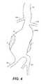
- FIG. 4illustrates the anatomy of an infrarenal abdominal aortic aneurysm.
- FIGS. 5A-5Dillustrate use of the prosthesis system of FIG. 1 for treating the infrarenal abdominal aortic aneurysm.
- FIG. 6illustrates an example of a system with a pair of prosthesis for delivery to an infrarenal abdominal aortic aneurysm, where each prosthesis comprises a filling structure mounted on a delivery catheter.
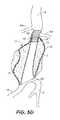
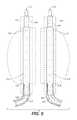
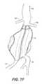
- FIGS. 7A-7Fillustrate use of the prosthesis system of FIG. 6 for treating an infrarenal abdominal aortic aneurysm.
- FIG. 8illustrates an example of a delivery catheter shaft carrying a single prosthesis system which comprises a filling structure mounted over a endoframe structure.
- FIG. 9illustrates an example of a system comprising a pair of prostheses for delivery to an infrarenal abdominal aortic aneurysm, where each prosthesis comprises a delivery catheter shaft carrying a fining structure mounted over an endoframe structure.
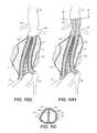
- FIGS. 10A-10Iillustrate exemplary usage of the system of FIG. 9 for treating an infrarenal abdominal aortic aneurysm.
- FIGS. 11A-11Billustrates an exemplary system having a fenestrated nosecone during advancement of the system in the vasculature and during deployment of the filling structure at the treatment site, respectively.
- FIG. 12shows an exemplary aneurysm treatment system having a fenestrated nosecone, a carrier knob and a handle.
- FIG. 13illustrates the fenestrated nosecone of the system of FIG. 12 .
- FIG. 14depicts angiography as performed with the nosecone of FIG. 12 .
- FIG. 15illustrates the annular carrier knob of the system of FIG. 12 .
- FIG. 16illustrates the handle of the system of FIG. 12 .
- FIG. 17illustrates an exemplary pressure monitor.
- FIGS. 18 and 19A-19Cillustrate an exemplary embodiment and cross-sections of the embodiment.
- FIGS. 20A-20Eillustrates exemplary coupling mechanisms of an aneurysm treatment system, in accordance with several embodiments.
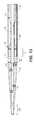
- FIGS. 21 and 22show two lateral views of a catheter treatment system, the catheter of FIG. 21 is shown in its as shipped configuration, i.e., prior to initiating deployment, where the sheath retraction knob, end handle, fluid connection, and endobag release wire fittings are in their pre-deployment configuration.
- FIG. 22shows a configuration of the catheter with the sheath having been retracted, i.e., after deployment has been initiated.
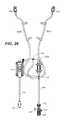
- FIG. 23is a lateral view showing two separate and discrete catheter treatment systems/devices as in FIG. 21 , where filling structure fill tubing, endoframe/expansion balloon pressurization tubing, and a guidewire lumen flush or contrast solution supply tubing from each catheter is connected to a sequential deployment step indicating single operator manifold console used to simultaneously pressurize and operate the function of both catheters from one operating input and location.
- FIG. 23is a lateral view showing two single catheter treatment systems configure for operation with a single operator manifold console.
- FIG. 24is a plan view of the single operator manifold console of FIG. 23 .
- FIG. 25is a cut-away plan view of the piping/tubing layout, showing the piping layout to, through, and out of the single operator manifold console of FIG. 24 .
- FIG. 26is a cut-away diagram of the piping/tubing layout of the single operator manifold console of FIG. 24 , isolating the piping system used for the application of vacuum to the endobag piping system.
- FIG. 27is a cut-away diagram of the piping/tubing layout of the single operator manifold console of FIG. 24 , isolating the piping system used for the application of pressure and vacuum to the endoframe/balloon piping/tubing system.
- FIG. 28is a cut-away diagram of the piping/tubing layout of the single operator manifold console of FIG. 24 , isolating the piping system used for the supply of pressurized polymer through the endobag pressurization piping/tubing.
- FIG. 29is a cutaway diagram of the piping layout of the single operator manifold console of FIG. 24 showing the piping/tubing layout for the application of angiography contrast solution to the catheter treatment system through the guidewire lumen.
- a system 10is for delivering a double-walled filling structure 12 to an aneurysm includes the filling structure and a delivery catheter 14 having an expandable element, typically an inflatable balloon 16 , at its distal end.
- the catheter 14will comprise a guidewire lumen 18 , a balloon inflation lumen (not illustrated) or other structure for expanding other expandable components, and a filling tube 20 for delivering a filling medium or material to an internal space 22 of the double-walled filling structure 12 .
- the internal space 22is defined between an outer wall 24 and inner wall 26 of the filling structure.
- the outer wallUpon inflation with the filling material or medium, the outer wall will expand radially outwardly, as shown in broken line, as will the inner wall 26 , also shown in broken line. Expansion of the inner wall 26 defines an internal lumen 28 .
- the expandable balloon 16 or other structurewill be expandable to support an inner surface of the lumen 28 , as also in broken line in FIG. 1 .
- the various internal and external surfacesmay be shaped, coated, treated, or otherwise modified, to provide for a number of potentially desirable features of the present apparatus.
- the external surface 24 ′ of the outer wallmay be shaped to have rings, stipples, or other surface features 26 ′ which are typically formed into the material of the structure at the time of molding, vapor deposition, or other manufacturing process.
- the outer surfacemay also be coated with materials 29 which can be adhesives, drugs, active substances, fibers, flocking, foams, or a variety of other materials. In most cases, such surface features or modifications will be intended to enhance sealing or attachment of the outer wall 24 to the inner surface of the aneurysm being treated.
- the inner surface 30 of the filling volume 22may also be modified by providing features 26 ′, coatings, surface roughening, coated with materials 29 , or a variety of other modifications.
- the purpose of such internal featuresis typically to enhance adherence of the walls to the filling material or medium as the medium is cured or otherwise hardened.
- materialsmay be coated on all or a portion of the inside surface 30 to induce or catalyze hardening of the filling material as it is being introduced.
- the double-walled filling structure 12will typically comprise at least one valve 35 to permit the introduction of the filling material or medium into the internal volume 22 using filling tube 20 .
- the valve 35may be a simple flap valve. Other more complex ball valves, and other one-way valve structures may be provided. In other instances, two-way valve structures may be provided to permit both filling and selective emptying of the internal volume 22 .
- the filling tubemay comprise a needle or other filling structure to pass through the valve 35 to permit both filling and removal of filling medium.
- the wall structure of the double-walled filling structuremay be a single layer, typically molded or otherwise conventionally formed.
- the wall structuresmay also be more complex, as illustrated for example, FIGS. 3A-3C .
- FIG. 3Ashows a multi-layered wall comprising layers 42 , 43 and 44 . It will be appreciated that such multiple layer structure can provide for increased strength, puncture resistance, variations in compliance and/or flexibility, differences in resistance to degradation, and the like.
- a single wall or multiple wall structurecan be reinforced by braid, coils, or other metal or non-polymeric reinforcement layers or structures 48 .
- the external surface 24 ′ of the wallmay be covered with drugs, fibers, protrusions, holes, active agents or other substances for a variety of purposes.
- an infrarenal abdominal aortic aneurysmcomprises the thoracic aorta (TA) having renal arteries (RA) at its distal end above the iliac arteries (IA).
- the abdominal aortic aneurysm (AAA)typically forms between the renal arteries (RA) and the iliac arteries (IA) and may have regions of mural thrombus (T) over portions of its inner surface (S).
- the system 10 of FIG. 1may be utilized to treat the complex geometry of the transmural abdominal aortic aneurysm (AAA) of FIG. 4 by first positioning the delivery catheter 14 to place the double-walled filling structure 12 (in its unfilled configuration) generally across the aneurysm from the region of the aorta beneath the renal arteries (RA) to a region over the iliac arteries (IA), as best seen FIG. 5A .
- the delivery catheter 14will be introduced over a guidewire (GW) through a puncture in the patient's groin accessing the iliac artery by the Seldinger technique.
- GWguidewire
- a hardenable inflation mediumis introduced into the internal space 22 filling of the inner space 22 and expands the outer wall 24 of the structure outwardly so that it conforms to the inner surface (S) of the aneurysmal space.
- the balloon 16 or other expansible structurewill also be inflated or expanded to open the tubular lumen defined by the interior of the inner wall 26 .
- a non-compliant balloon 16will be used, typically having a maximum diameter of width which is at or slightly larger than the desired tubular lumen diameter or width through the deployed double wall filling structure 12 .
- the filling structure 12may be partially or completely formed from a generally compliant material, thus allowing the non-compliant balloon 16 or other expansible structure to fully open the tubular lumen and conform the ends of the lumens to the aorta and iliac walls, as illustrated in FIG. 5C .
- a lower or distal end 50 of the tubular lumenmay be flared to a larger diameter so that it can accommodate the openings into both of the iliac arteries (IA) as illustrated.
- the filling structure 12 geometrycan be chosen to most closely match the particular patient geometry being treated as determined during pre-treatment planning.
- a balloon 16 or other expansible structurewhich will be shaped to preferentially open the lower distal end 50 of the tubular lumen to a larger diameter than the upper or proximal end 52 can be used.
- the fluid filling materialAfter the filling material has been introduced to the filling structure 12 , typically through the filling tube 20 , the fluid filling material must be cured or otherwise hardened to provide for the permanent implant having a generally fixed structure which will remain in place in the particular aneurysmal geometry.
- Methods for curing or hardening the filling materialwill depend on the nature of the filling material. For example, certain polymers may be cured by the application of energy, such as heat energy or ultraviolet light. Other polymers may be cured when exposed to body temperature, oxygen, or other conditions which cause polymerization of the fluid filling material. Still others may be mixed immediately prior to use and simply cure after a fixed time, typically minutes. Often, after the filling material has been hardened, the delivery catheter 14 may be removed and the filling structure left in place as the completed prosthetic implant.
- a stent-like structure 160may be planted in the upper proximal end opening of the tubular lumen of the filling structure 12 in order to help anchor the structure, help prevent intrusion of blood into the region between the outer wall 24 and inner surface (S) of the aneurysm, and to generally improve the transition from the aorta into the tubular lumen.
- the sealing or anchoring structuremay simply comprise a stent-like component, preferably having a port or other access route to allow blood flow into the covered renal arteries (if any).
- the anchor structurecould be another inflatable unit, such as the anchor described in co-pending, commonly owned application US Patent Application US2004/0116997A1, the full disclosure of which is incorporated herein by reference.
- FIG. 6A system comprising such a pair of filling structures is illustrated in FIG. 6 which includes a first filling structure 112 and a second filling structure 212 .
- Each of the filling structures 112 and 212are mounted on delivery catheters 114 and 214 , respectively.
- the components of the filling structures 112 and 212 and delivery catheters 114 and 214are generally the same as those described previously with respect to the single filling structure system 10 of FIG. 1 .
- each of the fillings structures 112 and 212will be given identical numbers with either the 100 series base number or 200 series base number.
- the difference between the filling structures 112 and 212 , on the one hand, and the filling structure 12 of FIG. 1is that the pair of filling structures may generally have slightly smaller filling volume configurations as they only need to occupy an approximately complimentary half the volume of the aneurysm which are meant to be positioned adjacent to each other within the aneurysmal space and to in combination fill that space, as will be described with specific reference to FIG. 7A-7F below.
- a pair of guidewireswill first be introduced, one from each of the iliac arteries (IA). As illustrated in FIG. 7A .
- the first delivery catheter 114will then be positioned over one of the guidewires to position the double-walled filling structure 112 across the aortic aneurysm (AAA), as illustrated in FIG. 7B .
- the second delivery catheter 214is then delivered over the other guidewire (GW) to position the second filling structure 212 adjacent to the first filling structure 112 within the aneurysm (AAA), as illustrated in FIG. 7C .
- FIG. 7Da partially filled (in process) filling condition is illustrated in FIG. 7D where the filling structure 112 and balloon 116 are shown being simultaneously inflated to simultaneously expand to fill the aneurysmal volume, as illustrated in FIG. 7D .
- FIG. 7EA completed filing is illustrated in FIG. 7E .
- the upper ends of the balloons 116 and 216will conform the tubular lumens of the filling structures against the walls of the aorta as well as against each other, while the lower ends of the balloons 116 and 216 will conform the tubular lumens into the respective iliac (IA).
- the filling materials or mediumwill be cured or otherwise hardened, and the delivery catheters 114 and 214 removed, respectively.
- the hardened filling structureswill then provide a pair of tubular lumens opening from the aorta beneath the beneath the renal arteries to the right and left iliac arteries, as shown in broken line in FIG. 7 .
- the ability of the filling structures 112 and 212 to conform to the inner surface (S) of the aneurysm, as shown in FIG. 7Fhelps assure that the structures will remain immobilized within the aneurysm with little or no migration.
- Immobilization of the filling structures 112 and 212may be further enhanced by providing any of the surface features described above in connection with the embodiments of FIG. 2 .
- anchoring or sealing structurescould be provided in either of the upper or proximal openings of the tubular lumens into the aorta or from either of the distal or lower openings into the respective iliac arteries.
- FIG. 8shows a system 10 constructed for delivering a double-walled filling structure 12 (also referred to as an endograft in this disclosure) to an aneurysm. It includes the filling structure 12 disposed over a radially expandable endoframe 19 , both of which are then mounted on a inner delivery catheter shaft 17 having an expandable element, typically an inflatable balloon 16 , near its distal end and a nosecone 33 at its distal end.
- Nosecone 33may be shaped to facilitate advancement of the delivery system through the vasculature and may include a series of side ports 34 for performing angiography before, during, or after deployment of the filling structure 12 .
- An outer sheath 40is slidably disposed over the inner delivery catheter shaft 17 , the distal end of which interfaces with a proximal portion of nosecone 33 so as to facilitate advancement of the system through the vasculature of the patient.
- Expandable element 16traverses the entire length of the endoframe 19 so that the endoframe 19 may be radially expanded upon expansion of the expandable element balloon 16 (expanded balloon 16 ′ shown in broken line).
- Endoframe 19traverses the entire length of filling structure 12 and most of endoframe 19 is covered by filling structure 12 , however, endoframe 19 may also have proximal and a distal regions that extend uncovered beyond the filling structure 12 .
- the catheter 14will comprise a guidewire lumen (not shown), a balloon inflation lumen (not shown) or other structure for expanding other expandable components, and a filling tube 20 for delivering a filling medium or material to an internal space 22 of the double-walled filling structure 12 .
- the internal space 22is defined between an outer wall 24 and inner wall 26 of the filling structure.
- the outer wall 24Upon inflation with the filling material or medium, the outer wall 24 will expand radially outwardly (expanded outer wall 24 shown in broken line) as will the inner wall 26 (expanded inner wall 26 ′ shown in broken line). Expansion of the inner wall 26 defines an internal generally tubular lumen 28 through which blood flows after deployment of the filling structure in the aneurysm.
- the expandable balloon 16 or other structurewill be expandable to correspondingly expand the endoframe 19 to provide support and to shape an inner surface of the lumen 28 .
- the expandable balloonis cylindrically shaped and therefore the generally tubular lumen 28 will also be cylindrically shaped.
- the balloonmay be pre-shaped to more precisely match the curvature of the vessel.
- a tapered, pre-shaped or curved balloonmay be used so that the lumen substantially matches the aorta.
- Various balloon configurationsmay be used in order to match vessel tortuosity.
- Pre-shaped, curved or tapered balloonsmay be used in any of the embodiments disclosed herein in order to obtain a desired lumen shaped.
- FIG. 9A system comprising such a pair of filling structures is illustrated in FIG. 9 which includes a first filling structure 112 and a second filling structure 212 .
- Each of the filling structures 112 and 212are mounted on delivery catheter inner shafts 114 and 214 , respectively and each system also has a radially expandable endoframe 127 , 227 .
- Inner delivery catheter shafts 114 and 214include fenestrated nosecones 133 , 233 for performing angiography before, during or after treatment, and outer sheaths 140 , 240 slidably disposed over the filling structure during advancement of the system through the vasculature along the guidewires (GW).
- the components of the filling structures 112 and 212 , the endoframes 127 , 227 and inner delivery catheter shafts 114 and 214are generally the same as those described previously with respect to the single filling structure system 10 of FIG. 8 .
- Corresponding parts of each of the filling systems 112 and 212will be given identical numbers with either a 100 series number or a 200 series number.
- Filling structures 112 and 212will generally be positioned adjacent each other within the aneurysmal space to fill that space, as will be described with specific reference to FIGS. 10A-10I below.
- FIGS. 10A-10Iillustrate an exemplary use of the system in FIG. 9 for treating an infrarenal abdominal aortic aneurysm AAA with or without mural thrombus T.
- the outer sheaths 140 and 240are retracted relative the inner catheter shaft 114 and 214 .
- the outer sheaths 140 and 240are slidably disposed over the filling structures 112 and 212 and the corresponding endoframes 127 and 227 disposed therein.
- FIG. 10A-10Iillustrate an exemplary use of the system in FIG. 9 for treating an infrarenal abdominal aortic aneurysm AAA with or without mural thrombus T.
- a pair of guidewireswill first be introduced preferably percutaneously or by surgical cut down, from each of the iliac arteries (IA) and advanced across the aneurysm toward the renal arteries (RA).
- the first delivery catheter shaft 114 having a fenestrated nosecone 133 at its distal end and an expandable balloon 116 disposed on a distal portionwill then be advanced over one of the guidewires GW to position the double-walled filling structure 112 across the aortic aneurysm (AAA) along with endoframe 127 .
- An outer sheath 140slidably disposed over the filling structure 112 and inner shaft 114 , is retracted to expose the filling structure 112 at the target treatment site.
- the second inner catheter shaft 214 having expandable balloon 216 and fenestrated nosecone 233 at its distal endis then delivered over the other guidewire GW to position the second filling structure 212 adjacent to the first structure 112 across the aneurysm (AAA) along with endoframe 197 , as illustrated in FIG. 10C .
- the outer sheath 240slidably disposed over the filling structure 212 and inner shaft 214 , is retracted to expose the second filling structure 212 at the target treatment site.
- the balloon 116 or 216is expanded. Expanding the balloon 116 or 216 expands the corresponding filling structure 112 or 212 and endoframe 127 , 227 disposed thereon. Next, the expanded filling structure 112 or 212 is filled with the fluid filling medium. Then, the balloon 116 or 216 is deflated to allow a flow of blood through the filling structure 112 , 212 filled with the fluid filling medium, while the expanded endoframe 127 , 227 maintains the patency of the generally tubular lumen within the expanded filled filling structure 112 or 212 .
- filling structures 112 or 212are be filled with the fluid filling medium first, then the balloon 116 or 216 expanded to expand the endoframe 127 or 227 to form a generally tubular lumen in the corresponding filling structure 112 or 212 .
- filling structure 112 or 212is filled with the fluid filling medium simultaneously with expanding the balloon 116 or 216 disposed therein.
- Typical variations of deployment proceduresmay include: one of the filling structures 112 , 212 and associated balloons 116 , 216 being expanded first along with the corresponding endoframe 127 , 227 , followed by the other filling structure, endoframe and balloon. As discussed in the configurations described below, both balloons are radially expanded simultaneously thereby also expanding the filling structures and endoframes simultaneously.
- one or both filling structures 112 , 212may be filled with a hardenable material and then the filling structures 112 , 212 are radially expanded along with the corresponding endoframe 127 , 227 .
- combinations of filling and expandingmay be performed in different order depending on physician preference and aneurysm anatomy.
- an optional pre-filling stepmay be performed prior to filling with the hardenable filling medium.
- the filling structuremay be filled with CO 2 gas, contrast media, saline or other fluids to unfurl the filling structure 12 away from the delivery catheter thereby helping to ensure more uniform filling later on and reduce or eliminate stiction between folds of the filling structure that may be present.
- the filling structuremay be partially filled or fully filled so that it conforms to the inner aneurysm wall.
- angiographymay be performed through a fenestrated nosecone 133 or 233 on the inner catheters shafts 114 or 214 upstream of the aneurysm to detect leaks in the deployed filling structure 12 .
- the fluidmay be removed from the filling structure and it may be filled with the hardenable material to expand and conform to the aneurysmal space between the lumens and the inner aneurysm wall.
- Pressure relief valvessuch as those described herein may also be used to ensure that the filling structure is not over filled. In order to prevent overfilling of the filling structure, any of the pressure relief valves disclosed below may also be used to bleed off excess fluid from the filling structure.
- FIG. 10Dillustrates the simultaneous inflation of both balloons 116 , 216 along with endoframes 127 , 227 in addition to expansion and filling of filling structures 112 , 212 .
- the filling structures and balloonsare expanded and inflated to fill the aneurysmal volume in contact with the aneurysmal wall and each other, as illustrated in FIG. 10E .
- U.S. Patent Publication No. 2006/0212112discloses filling of one filling structure in more detail including pressures, filling materials and other details, the entire contents of which have previously been incorporated herein by reference.
- FIG. 10Ealso illustrates a cut away view of the expanded endoframes 127 , 227 within the filled filling structures 112 , 212 .
- the upper ends of the balloons 116 and 216will conform the tubular lumens of the filling structures against the walls of the aorta as well as against each other, while the lower ends of the balloons 116 and 216 will conform the tubular lumens into the respective iliac artery, IA.
- the expanded endoframe 127not only provides support to filling structure 112 , but also creates and shapes a lumen for blood passage from the aorta to one of the iliac arteries.
- expanded endoframe 197also provides a lumen for blood passage from the aorta into the other iliac artery.
- filling of the filling structuresmay be performed before, during or after radial expansion of the balloons and the endoframe 127 , 227 (either both expanded simultaneously or one after the other).
- the endoframes 127 , 227may be radially expanded using a cylindrically shaped balloon to form a substantially cylindrically shaped lumen. Curved, tapered or pre-shaped balloons may also be used to expand the endoframes 127 , 227 , thereby forming a lumen that also is curved, tapered or shaped.
- the curved, tapered or pre-shaped balloonmay be selected to match the anatomy of the vessel in which the endoframe and endograft is placed.
- Pre-shaped, curved or tapered balloonsmay be used in any of the other embodiments disclosed herein in order to obtain a desired lumen shape.
- the filling materials or mediumwill be cured or otherwise hardened as described in U.S. Patent Publication No. 2006/0212112 and the inner delivery catheter shafts 114 and 214 removed, respectively.
- the hardened filling structures along with the expanded endoframes 127 , 227will then provide a pair of tubular lumens opening from the aorta beneath the renal arteries to the right and left iliac arteries, as shown more clearly in broken line in FIG. 10F .
- the double filling structure embodimentsmay include at least one endoframe deployed within each of the tubular blood flow lumens.
- the endoframeswill generally be endoskeletal structures that lay the foundation for new lumens, and will be deployed within the tubular lumens of the double-walled filling structures using balloon or other expansion catheters (in the case of malleable or balloon-expandable endoframes) and an optional retractable constraining sheath.
- FIG. 10Gmore clearly shows the first endoframe 127 disposed within the generally tubular lumen of the first filling structure 112 while a second endoframe 197 is disposed in the tubular lumen of the second filling structure 212 .
- the endoframesare balloon expandable structures which extend into the iliac arteries IA at the lower end of the filling structures.
- the endoframesmay be self-expanding endoframe-like structures fabricated from a shape memory alloy such as Nitinol.
- first and second endoframes 127 and 227may extend upwardly on the aortic side of the first and second filling structures 112 and 212 .
- the first and second endoframes 127 and 227may be constructed so as to not obstruct the renal arteries.
- the first and second filling structure 112 and 212may include a side hole so as to allow flow of blood through the renal arteries (RA).
- RArenal arteries
- the upper ends of the endoframes 127 , 227may be formed from their respective expansion balloons and manufacturing shape treatments to have D-shaped cross-sections when expanded, although other cross-sections such as elliptical, circular, etc. may be formed.
- flat faces 258 and 260will engage each other with the remaining portion of the endoframe conforming to the inner wall of the aorta. In this way, most of the cross-sectional area of the aorta will be covered with the endoframe, thus enhancing blood flow through the filling structures.
- Other configurationsare disclosed in U.S. Patent Publication No. 2006/0212112 previously incorporated herein by reference.
- each endoframe and filling structureis both disposed coaxially and generally concentrically over an expandable member coupled to a delivery catheter and the entire system is delivered to the aneurysm at one time.
- a coaxial and concentric systemtypically includes a filling structure 12 , also referred to as an endograft that is coaxially disposed over the endoframe 19 , both of which are then coaxially and concentrically positioned over a radially expandable balloon 16 which is coupled to the distal region of a inner shaft 17 .
- Proximal and distal portions of endoframe 19may extend uncovered by filling structure 12 and a filling tube 20 allows a fluid to be delivered to the filling structure 12 .
- endoleaksoccur, thereby resulting in incomplete occlusion of the aneurysm.
- a separate angiography cathetermay be useful to visualize the blood flow through the aneurysm and detect endoleaks during deployment, a separate angiography catheter would likely increase the profile and further complicate the method of delivery.
- the filling structuremay move relative to the endoframe during delivery, thereby resulting in inaccurate placement of one or both devices.
- an integrated systemprovide a system that can perform an angiography procedure without substantially increasing the profile of the delivery system or over complicating the procedure. It would be further advantageous for such a system to provide more effective ways of coupling the filling structure and endoframe to the delivery catheter to inhibit movement and facilitate more accurate delivery of the endoframe and endograft to the treatment site.
- FIGS. 11A-11Billustrate an exemplary embodiment of a delivery system having a fenestrated nosecone 33 and a retractable outer sheath 40 , as shown both during delivery of the system to the aneurysm ( FIG. 11A ) and during deployment of the filling structure at the aneurysm ( FIG. 11B ).
- the exemplary embodimentincludes an inner shaft 17 having a filling structure 12 and endoframe 19 disposed thereon, and an outer sheath 40 slidably disposed over the inner shaft 17 , filling structure 12 and endoframe 19 .
- Nosecone 33attached to the distal end of inner shaft 17 , includes a lumen extending therethrough, preferably a single through lumen, the through lumen connected to a guidewire lumen of the inner shaft 17 , such that the nosecone and inner shaft can be simultaneously advanced along the same guidewire GW.
- the noseconeincludes a series of sideports 34 in fluid communication with the through lumen for performing angiography before, during or after deployment of the filling structure 12 .
- the systemincludes releasable coupling mechanisms to attach filling 10 and endoframe 19 to inner delivery catheter 17 during delivery of the system to the aneurysm (shown in detail in FIGS. 20A-20E ).
- outer sheath 40releasably couples with the nosecone to facilitate advancement of the system through a patient's vasculature, as illustrated in FIG. 11A .
- a marker band 31may be disposed near the interface on one or both of the proximal portion of nosecone 33 and the distal end of the outer sheath 40 , so as to allow a user to visualize the location of the outer sheath 40 relative to the filling structure 12 .
- the fenestrated noseconeremains attached to the end of the inner shaft 17 distal of the filling structure 12 so that an angiography procedure may be performed.
- a contrast media 38may be injected through the guidewire lumen of the inner shaft 17 and out through the side ports 34 of the nosecone 33 into the vasculature.
- outer sheath 40is retracted by pulling proximally on an annular knob 57 depicted in FIG. 15 . After deployment and release of the filling structure and endoframe from the inner catheter, outer sheath 40 can be advanced, typically using knob 57 , so as to interface with nosecone 33 to facilitate withdrawal of the system from the patient.
- FIG. 12shows an exemplary embodiment of the delivery system, which includes the fenestrated nosecone 33 , an outer sheath 40 , a filling structure 12 (not shown) disposed within outer sheath 40 , an annular carrier knob 57 for retracting the outer sheath 40 , and a handle 60 .
- the systemas shown in FIG. 12 , is inserted into the vasculature of the patient.
- the distal tapered shape of nosecone 33 and the smooth transition between the nosecone 33 and outer sheath 40 coupled theretofacilitates advancement of the system through the vasculature of the patient.
- the physicianmay retract the outer sheath 40 by pulling carrier knob 57 proximally, thereby retracting outer sheath 40 over hypotube 41 proximal of knob 57 .
- the carrier knob 57is fixedly attached to the proximal end of outer sheath 40 and includes a seal between outer sheath 40 and hypotube 41 .
- Handle 60disposed at the proximal end of inner shaft 17 is used to advance and withdraw the system, as well as to deploy the (fillable) filling structure 12 or perform angiography through nosecone 33 .
- FIG. 13illustrates the nosecone 33 of the embodiment of FIG. 12 in more detail.
- nosecone 33may be incorporated into any of the embodiments disclosed herein.
- Nosecone 33is distally tapered and includes a through lumen 18 extending along a longitudinal axis of the nosecone to facilitate advancement of the system over a guidewire through the vasculature.
- Nosecone 33is also fenestrated having a series of sideports in fluid communication with the through lumen for performing angiography.
- the through lumen 18 of the noseconeis sized so as to simultaneously receive a guidewire and a flow of contrast media for performing angiography through the side ports 34 .
- the fenestrated nosecone 33is advantageous as it facilitates both advancement of the system over a guidewire and delivery of contrast media in an angiography procedure through the same lumen while the guidewire is disposed therein, thereby simplifying the procedure while maintaining a reduce profile.
- nosecone 33releasably couples or interfaces with the distal end of outer sheath 40 .
- nosecone 33includes an isodiametric portion 36 which is isodiametric with the outer diameter of the distal end of outer sheath 40 so as to create a smooth transition at the interface and prevent “snowplowing” against a vessel wall as the system advances through the patient's vasculature.
- Isodiametric portion 36extends a distance distal of the interface so as to increase the stiffness of the nosecone near the interface and prevent flexure of the nosecone and/or outer sheath at the interface during advancement of the system.
- Nosecone 33may also include a portion 37 having an outside diameter slightly smaller than the inside diameter of the distal end of outer sheath 40 ; thus, portion 37 is disposed within the outer sheath 40 such that the outer sheath 40 fittingly receives portion 37 so as to releasably couple with the nosecone 33 .
- Portion 37may extend a distance proximal of the interface so as to increase the stability of the coupling and to increase the stiffness near the interface to prevent separation between the nosecone and outer sheath 40 as the system winds through complex or tortuous vasculature, thereby further reinforcing the smooth transition between the nosecone 33 and the outer sheath 40 to reduce the likelihood of “snowplowing” against the vessel wall.
- the nosecone 33 and/or the outer sheath 40may further include a radiopaque marker band 31 near the interface to allow a physician to image the location of the distal end of the outer sheath 40 relative to nosecone 33 .
- the resin to manufacture the noseconemay also include a radiopaque filler to facilitate imaging during the procedure.
- Nosecone 33is dimensioned to facilitate advancement in a patient's vasculature.
- An exemplary noseconemay be between 1 to 4 inches in length, preferably 2.5 to 3 inches, and have an outside diameter tapering from about 0.25 inches at a proximal end to about 0.050 inches at a distal end.
- the through lumen 18 extending through the nosecone 33may also reduce in size as the outside diameter tapers down.
- the through lumen at the proximal end 32 Bmay be between 0.05 and 0.1 inches, preferably about 0.08 inches, and reduce in size gradually or incrementally to 0.02 to 0.04 inches, preferably about 0.05 inches at the distal portion 32 A of nosecone 33 .
- Angiographymay be performed by injecting a contrast media through the guidewire lumen of the inner shaft 17 , which then flow into the through lumen 18 of nosecone 33 and out the side ports 34 , preferably while the guidewire GW is disposed within the guidewire lumen and through lumen 18 .
- Angiographymay be performed through nosecone 33 before, during, or after treatment of the aneurysm, and is useful for imaging the flow of blood, particularly for detecting leaks in an endograft deployed in an aneurysm.
- a radiopaque contrast mediais delivered into a blood vessel and an X-ray based imaging technique, such as fluoroscopy, is used to image the flow of the contrast media as it flows through the blood vessel.
- an X-ray based imaging techniquesuch as fluoroscopy
- fenestrated nosecone 33includes pairs of side ports 34 arranged in a series equally distributed along the nosecone in a helical fashion so as to evenly distribute the contrast media into the vasculature.
- each of side ports 34extends in an orthogonal direction from the longitudinal axis of the nosecone 33 .
- the nosecone 33comprises a series of 4 to 10 pairs of side ports 34 , preferably 5 to 7 pairs of side ports, arranged in a helical fashion as described above.
- a side port 34has a diameter within a range of 0.01 inches to 0.05 inches, and more preferably within a range of 0.03 to 0.04 inches.
- FIG. 14illustrates the nosecone 33 having a guidewire GW disposed within guidewire lumen 18 as well as a flow of contrast media 38 through a portion of guidewire lumen 18 .
- the guidewire lumen 18includes a distal portion 32 A which is reduced in size from the guidewire lumen 18 at the proximal end of nosecone 33 .
- Distal portion 32 A of the through lumen 18is sized to slidably receive the guidewire and fit so as to inhibit flow of contrast media through the distal opening when the guidewire is disposed therein.
- the portion of the through lumen 18 proximal of portion 32 Ais sized to simultaneously receive the guidewire and facilitate flow of contrast media 38 .
- the narrowed distal region 32 A of through lumen 18substantially inhibits flow of contrast media through the distal opening of the nosecone, thereby directing the flow of contrast media through the side ports 34 and into the vasculature of the patient, as illustrated in FIG. 14 .
- FIG. 15illustrates the carrier knob of the system of FIG. 12 , the carrier knob coupling the proximal end of outer sheath 40 with hypotube 41 .
- the outer sheath 40is slidably disposed, at least partially, over hypotube 41 (main catheter shaft) when outer sheath 40 is retracted.
- hypotube 41main catheter shaft
- outer sheath 40is retracted relative to the inner shaft 17 to expose the filling structure 12 , endoframe 19 and expandable member, i.e., balloon 16 , on a distal region of inner shaft 17 .
- the carrier knob 57is fixedly coupled to the proximal end of the outer sheath 40 , preferably with a heat bond, so that a physician may manually pull the carrier knob 57 to retract outer sheath 40 over hypotube 41 .
- Carrier knob 57may also include an internal seal.
- the carrier knob 57may comprise any material, such as polyetheramide, which can be bonded with the outer sheath 40 .
- Carrier knob 57may include an internal seal 56 , such as an silicone O-ring, to prevent fluid outflow from between the distal and proximal segments of the outer sheath 40 .
- an internal seal 56such as an silicone O-ring
- the blood pressure of the patient against internal seal 56is sufficient to prevent fluid outflow from the body between outer sheath 40 and hypotube 41 .
- Carrier knob 57may be heat bonded to the outer sheath 40 by covering the proximal end of outer sheath 40 by a laminate material, preferably a polymer material such as Pebax®, placing a cavity in the knob 57 over the laminate covered outer sheath 40 , and heating the assembly so that the laminate bonds to the outer shaft 40 and/or the knob 57 , preferably bonding with both the outside surface of outer sheath 40 and the inside surface of the knob 57 .
- the systemmay further include a retaining mechanism to prevent the hypotube 41 from slipping out of the knob 57 when the outer sheath 40 is advanced.
- the retaining mechanismmay comprise a collar, a ring, a pin, a screw or any mechanism suitable to maintain a slidable coupling between the hypotube 41 and the annular knob 57 .
- the systemmay also include a keying mechanism to prevent rotation between hypotube 41 (main catheter shaft) and sheath 40 .
- Knob 57include a sheath flush line 63 , to allows flushing of the sheath or shooting contract through the sheath during the treatment procedure.
- FIG. 16illustrates a handle 60 of an exemplary delivery system of FIG. 12 .
- Handle 60include a body having a guidewire access port 61 , an angiography line 62 , a fill tube line 64 , a release wire port/connector 66 , and a balloon inflation line 68 .
- the angiography line 62provides access to the guidewire lumen such that contrast media can be injected through the guidewire lumen and out the series of side ports 34 of the nosecone 33 .
- the backend pressure needed to perform angiographymay reach 1,000 psi or more. These pressures may potentially cause the guidewire to “shoot” out of the guidewire lumen.
- the guidewire access port 61may include a locking mechanism for locking guidewire GW to the handle during the angiography process.
- angiography line 62provides access to the guidewire lumen, while the guidewire access 61 may seal and lock the guidewire GW into place.
- Release wire access port/connector 66provides access for removal of the release wire so as to decouple the coupling mechanisms and release the deployed filling structure from the inner shaft 17 .
- Release wire access port/connector 66may include a threaded luer type connector, which is fixed to the proximal end of the release wire, such that removing the port connector (along with the filling structure fill tube 64 ) and pulling in the proximal direction will retract the release wire and decouple the coupling mechanisms.
- handle 60may rotate on its inner and outer shafts to prevent undesired transfer of torque to the catheter shafts.
- a pressure monitor 69is utilized to monitor the filling structure filling pressure during the treatment procedure.
- the pressure monitoris fluidly coupled with the filling tube circuit so as to monitor the system filling pressure during filling of the filling structure 12 with the hardenable medium.
- pressure monitoringmay be utilized in the following way. After two filling structures have been delivered to the treatment site, both endoframes are radially expanded to help create a lumen for blood flow through the filling structure across the aneurysm. Using data from a patient's computerized tomography (CT) scans, a fill volume of the aneurysm treatment site may be estimated. This represents the baseline filling volume for both filling structure and is the minimum expected volume of filling material to be injected into the filling structure feed circuitry.
- CTcomputerized tomography
- Syringes or other injection devices coupled with a pressure gagemay be used to optionally pre-fill each filling structure with contrast material using the baseline volume and the resulting baseline fill pressure may be noted.
- the pressure monitoring systemmay include a pop-off valve to relieve excess pressure in the event of overfilling.
- the pressure monitoring systemmay include a sensor inside the filling structure and a sensor monitoring the patient's systolic and or diastolic blood pressure used for calculating the patient's differential blood pressure.
- a differential blood pressure reading between the filling structure and the patient's systolic and or diastolic pressuresimplifies the process of filling the structures as this allows the physician to accurately target the pressure inside the filling structure.
- a functional fill volumemay be determined. This volume is a percentage of the aneurysm volume obtained from the CT data, or it may be a predetermined number and is the volume of filling material that effectively seals and excludes the aneurysm.
- Functional fill pressurewill be the pressure at which the functional fill volume is attained.
- a polymer fill dispensermay then be used to fill each filling structure with the functional fill volume and the functional fill pressure is noted.
- the filling structureWhile holding the functional fill volume and pressure, the filling structure may be observed under fluoroscopy to check for proper positioning, filling and the absence of leakage across the aneurysm. If leaks are observed, additional polymer may be added to the filling structures until the leaks are prevented or minimized. Excessive additional polymer should not be added to the filling structure in order to avoid exceeding a safe fill volume or safe fill pressure. Once the physician is satisfied with the filling and positioning of the filling structures, stopcocks to the filling structures may be closed to allow the polymer to harden and then the delivery devices may be removed from the patient.
- FIG. 17illustrates a pressure monitor 69 comprising an integrated pressure gauge transducer.
- Pressure monitor 69may include a body 70 , a pressure fitting 71 , control buttons 72 , and a digital display 73 for reading the pressure and time output.
- the body 70may include pressure transducers for determining the pressure and/or differential pressure.
- Pressure fitting 71couples the pressure transducers of the body 70 to the filling system, control buttons 72 allow a user to adjust the pressure or the pressure or time readout.
- the pressure fitting 71may include a tubular member and a luer cap for fluidly coupling with a filling line of the delivery system 10 .
- Pressure monitor 69may be re-usable or disposable, preferably the pressure transducers are for a single use and are disposable.
- other pressure indicatorsmay also be used to facilitate determining the filling status of the filling structure.
- some embodimentsmay employ a relief valve.
- the relief valveis preset to a certain pressure such that beyond the preset pressure, any additional filling material will bleed out of the filling structure. While the relief valve may be adjacent the filling structure, preferably the filling material will be vented toward the proximal end (handle end) of the catheter, outside the body. This keeps potentially dangerous fluids or other filling material from being introduced into the body.
- the methodsmay also include use of a pressure monitoring system that allows a physician to monitor the pressure before, during or after filling the filling structure.
- the systemmay include a user interface for displaying the pressure output and may optionally include a time output displayed in conjunction with the pressure output.
- the monitoring systemmay also include a processor for analyzing the pressure data.
- the processormay be programmed to normalize the pressure data.
- the pressure monitoring systemenables the physician to closely monitor the filling pressure during deployment of the filling structure and may include additional functions to facilitate proper deployment, including: pressure cut-off switches, warning indicators if the measured filling pressure is outside an acceptable range, and pressure bleed off switches to optimize filling pressure and compensate for fluctuations in pressure during filling.
- the monitoring systemmay also record the pressure data during deployment. Additionally, in embodiments deploying two filling structures, the monitoring systems may be operatively coupled such that the system or a physician may monitor pressures during filling of one filling structure in response to pressure output readings from the other adjacent filling structures.
- Pressure monitoringcan also be performed at various stages of the aneurysm repair procedure to help control the filling process of the filling structure.
- the monitoring of pressuresserves to reduce the risk of dissection, rupture or damage to the aneurysm from over pressurization and also can be used to determine an endpoint for filling. Monitoring can be done before, during or after filling and hardening of the filling structure with filling medium. Specific pressures which can be monitored include the pressure within the internal space of the filling structure as well as the pressure in the space between the external walls of the filling structure and the inner wall of the aneurysm.
- a composite measurementcan also be made combining pressures such as those measured within the interior space of the filling structure, together with that in the space between the external walls of the structure and the aneurysm wall or other space at the aneurysm site and an external delivery pressure used by a fluid delivery device, such as a pump or syringe, to deliver the filling medium. Control decisions can be made using any one of these pressure measurements or a combination thereof Methods of pressure monitoring are discussed in detail in related commonly-owned applications: U.S. Pat. No. 7,666,220 and U.S. Patent Application No. US 20100036360 A1, the entire contents of which are incorporated herein by reference.
- the pressure monitor as shown in FIG. 17is used by an operator to monitor the filling pressure for the polymer being injected into the double wall filling structure 12 . While a vacuum is initially pulled on the double wall filling structure 12 , as described below, once the filling of the double wall filling structure 12 is initiated by the injection of polymer the associated pressure sensor monitor on the polymer tubing system as shown in FIG. 17 will detect the systemic blood pressure of the patient as the double walled filling structure 12 is surrounded by the patient's blood in the arterial system. As further injection of polymer progresses and any compressible fluid in the system becomes compressed (though there should be very little air or other compressible fluid in the system because a vacuum has been pulled on the system in the first step of the pressurization portion of the deployment procedure).
- the sensitivity of the pressure monitor to the blood pressure of the patient being treatedwill increase as more of the tubing system is filled with the liquid fluid (understood to be an incompressible fluid—which transmits pressure instantaneously).
- the systemwill then operate merely as a pressure sensor while the double walled filling structure 12 is unrestrained and surrounded by systemic blood pressurized in the normal manner by the patient's pulsating heart.
- Pressure monitors 69can be programmed to display various desired systemic blood pressure specific points in the cycle of the pulsating blood pressure of a patient's normal arterial function.
- the high pressurebeing the systolic pressure and the low pressure in a cycle being the diastolic pressure.
- the pressure monitorif so programmed, will provide a readout of both the systolic and diastolic pressures (two readings on one display face).
- the pressure monitor 69can be reprogrammed (it's firmware adjusted) to readout specifically selected pressure parameters, e.g., the systolic pressure, the diastolic pressure, or a mean pressure (which averages the systolic pressure and diastolic pressure).
- the length of the sampling (averaging) time of the pressures measured and then displayedcan also be adjusted in the pressure monitor 69 .
- the averaging of each parameter over timecan be taken over a selected range of seconds.
- the selected sampling rangesmay be 5 seconds, 10 seconds, or 15 seconds, or other intervals desired—and available in the hardware and programmable software of the pressure monitoring device.
- the monitorwill then update its digital display at each selected time interval.
- the operatorwill inject polymer into the double walled filling structure pressurization system and observe the diastolic pressure of the system.
- the diastolic pressurewill very according to system pressure (patients arterial blood pressure system pressure) until the outer wall of the double walled filling structure reaches the inner wall of the aneurysm.
- the inner wall of the double walled filling structurewhich is already adjacent to or situated on a support structure or endoframes (e.g., 19 ) will become restricted in its inward expansion as a result of resting on against the internal support structure or endoframe.
- endoframese.g., 19
- a monitoring of the pressure readout on the pressure monitor programmed to present either the diastolic pressure or the mean pressurewill provide information about the state of expansion of the double walled filling structure.
- the polymer injection/fillingshould continue until the diastolic (lower) pressure is increased to be equal to or below above the systolic readout so that the mean pressure and diastolic pressure readout of the pressure monitor 69 is nearly the same (in the instance where all three pressures can be read on a display or detected by various means (known to person skilled in the art) during an operation.
- the pressure monitor 69Once the endobag reaches its full expansion (limited from further expansion by the inner wall of the aneurysm), the pressure monitor 69 will no longer be measuring the system pressure or be sensing a variation system pressure.
- the diastolic pressurewill not vary very much and the pressure in the double walled filling structure 12 (the endobag) will be shown on the digital display 73 .
- the target pressure for the endobagis usually at or slightly above the expected systolic pressure of the patient being treated.
- the pressure the systemic pressure expected to be overcomeis in the range of 180 to 300 mmHg which is less than half an atmosphere (equal to 380 mmHg).
- FIG. 18illustrates and exemplary delivery system
- FIGS. 19A-19Cillustrate cross sections of the delivery system of FIG. 18
- FIG. 19Ashows cross-section A-A at a location proximal of the nosecone at which the filling structure 12 , endoframe 19 and balloon 16 are each disposed concentrically outside inner shaft 17 and inside of outer sheath 40
- FIG. 19Bshows cross-section B-B at a location distal of the carrier knob 57 at which concentric inner and outer filling tubes 20 A, 20 B are disposed adjacent concentric inner and outer balloon shafts 17 A, 17 B of inner shaft 17 within outer sheath 40 .
- FIG. 19Ashows cross-section A-A at a location proximal of the nosecone at which the filling structure 12 , endoframe 19 and balloon 16 are each disposed concentrically outside inner shaft 17 and inside of outer sheath 40
- FIG. 19Bshows cross-section B-B at a location distal of the carrier knob 57 at which concentric inner and outer fill
- 19Cshows cross-section C-C at a location between the handle 60 and carrier knob 57 at which concentric inner and outer filling tubes 20 A, 20 B are disposed adjacent concentric inner and outer balloon shafts 17 A, 17 B of inner shaft 17 within hypotube 41 .
- the outer sheath 40 and hypotube 41comprise different materials.
- the distal segment of outer sheath 40may comprise polyether block amide, while the segment of outer sheath 40 proximal of the carrier knob 57 may comprise 304 stainless steel.
- FIGS. 19B and 19Calso show an inner core 99 or filler that typically terminates about 2.5 cm from the proximal (illiac side) balloon bond to the balloon outer shaft.
- the inner core 99is typically a filler material, often a TPE material with a hardness of 70D (durometers on the D Shore scale) or lower (e.g. Pebax 6333).
- the inner core 99can be a solid of a low durometer material, such as Pebax 6333, or a pellethane may be used so long as the density of the inner core aids in pushability.
- the outer surface of the inner corecan be smooth or textured. Surface design of the inner core can be configured to provide a desired coefficient of friction low between it and the outer sheath.
- the distal end of the inner core 99stops about 2 to 2.5 cm from the balloon taper/neck transition to allow for the balloon to expand and inhibit kinking of the fill tube.
- This transitionis typically heat formed and UV bonded to create a tapered transition and to seal the lumens to ensure no air can pass through these lumens and inhibit back bleeding.
- the inner corecan terminate 1 cm into the handle hypotube or can run entirely through the handle hypotube. Ideally, at least 1 cm of the inner core extends inside the handle hypotube to ensure attachment and inhibit kinking at this location.
- FIGS. 20A-20Eillustrates coupling mechanisms of an exemplary delivery system.
- the coupling mechanismsinhibit movement of the filling structure and endoframe relative to the delivery catheter so as to facilitate positioning of the filling structure and endoframe at the aneurysm.
- FIG. 20Adepicts the coupling mechanisms during deployment of the filling structure, wherein the outer sheath 40 has been retracted and filling structure 12 has been partially filled.
- the coupling mechanismsmay include tethers 51 , 53 and/or tether loops for attaching filling structure 12 and endoframe 19 to inner shaft 17 .
- filling structure 12is disposed over endoframe 19 which is crimped onto expandable member 16 disposed near the distal end of inner shaft 17 .
- Two releasable coupling mechanisms, tethers 51 and 53 , along with release wire 46inhibit movement of filling structure 12 and endoframe 19 relative to inner shaft 17 during delivery and positioning at the aneurysm.
- Tether 51may comprise a tether loop fixedly attached to inner shaft 17 distal of the filling structure 12 , the tether loop extending through an opening in endoframe 19 and around release wire 46 , as shown in detail in FIG. 20E .
- Tether 51couples the endoframe 19 to inner shaft 17 so long as release wire 46 remains within the loop of tether 51 .
- the filling structure 12is indirectly coupled to inner shaft 17 , since endoframe 19 is also coupled to the filling structure 12 with sutures 47 . Once release wire 46 is withdrawn, tether loop 51 easily slips out through the opening in endoframe 19 and can be withdrawn with inner shaft 17 .
- Tether 53may comprise a tether loop fixedly attached to filling tube 20 , which then extends through a suture loop 45 on the proximal end of filling structure 12 and around the release wire 46 . So long as release wire 46 remains within the suture loop 45 , filling tube 20 remains coupled with the proximal end of filling structure 12 . Tether 53 may inhibit movement of the proximal region of the filling structure 12 during delivery, and may help prevent release of the fill tube 20 from the filing structure 12 .
- tether 53provides a fail safe mechanism prior to filling and during filling or re-filling of the filling structure, until the procedure is over, at which time the release wire can be retracted releasing the coupling between filling tube 20 and the filling structure 12 .
- the release wire 46can be withdrawn by pulling the proximal end of the release wire 46 from the handle 60 .
- the delivery system 10can be withdrawn from the body as tether loops 51 and 53 no longer couple the filling structure 12 or endoframe 19 to the system.
- the release wire 46extends the length of and runs parallel to inner shaft 17 .
- the distal end of release wire 46is releasably coupled to inner shaft 17 just proximal of the nosecone 33 , as shown in detail in FIG. 20D . This is to ensure the release wire does not interfere with deployment of the filling structure 12 .
- a UV adhesivesuch as Loctite 3321 may be applied to hold the knot and create a temporary bond between the release wire and the inner shaft.
- release wire 46is Teflon coated, so that the temporary bond easily delaminates and releases from inner shaft 17 when a physician pulls the proximal end of release wire 46 at handle 60 .
- the release wire 46may be made from polytetrafluroroethylene coated 304 stainless steel and sized so as to be easily withdrawn from between the filling structure 12 and the endoframe 19 after deployment.
- filling structure 12is coupled with the distal end of the endoframe 19 by one or more sutures 47 , preferably four sutures, disposed at regular intervals about the distal end of filling structure 12 .
- the sutures 47couple the filling structure 12 to endoframe 19 to maintain the relative position of the endoframe 19 during deployment and may also help anchor the filling structure 12 to the endoframe 19 after deployment of the filling structure 12 in the aneurysm.
- Other releasable coupling mechanismsincluding releasable knots, may be used and therefore the coupling mechanism is not limited to tether embodiments. Additionally, the tether may be used as a releasable coupling mechanism in any of the embodiments disclosed in this specification.
- suture 47comprises a single thread having one end attached to endoframe 19 and the other end attached to endoframe 19 , as shown in FIG. 20A .
- suture 47may comprise a suture loop, such as those depicted in FIG. 20B .
- Endoframe 19may include eyelets 49 near the proximal or distal ends of the endoframe through which the suture 47 can be looped to secure the filling structure 12 to the endoframe 19 . This way, the filling structure 12 will be fixed relative to the endoframe as long as the tether loops are taut.
- this coupling mechanismwill allow about ⁇ 5 mm and more preferably ⁇ 3 mm of relative movement between the filling structure and the endoframe.
- the filling structure and endoframeshould be positionable within ⁇ 7 mm and more preferably between ⁇ 5 mm of a target position within the aneurysm of the filling structure 12 .
- the four suturesare equally distributed about the distal end of the filling structure.
- the four suturesmay be attached to the filling structure and spaced apart radially at 0 degrees, 90 degrees, 180 degrees and 270 degrees.
- FIG. 21shows an undeployed configuration of delivery catheter 14 A which includes an end handle 60 A and a sheath retraction knob 57 A.
- Sheath 40 Ais coupled to the sheath retraction knob 57 A and is configured spaced apart from the end handle 60 A by a hypotube 41 A.
- the handle 60 Aincludes a guidewire access port 61 A through which a guidewire GW is passed.
- One half of a quick release color-coded tubing connector 82 Ais connected to the catheter end of the endobag pressurization piping/tubing.
- Endoframe pressurization piping/tubing 68 A(such as for balloon expansion within the endoframe) also passes into the handle 60 A and has its catheter end connected to one half of a quick release tubing connector 84 A.
- the handle 60 Aalso provides routing for guidewire lumen pressurization piping/tubing 62 A from one half of a quick release connector 86 A at the catheter end of the tubing, to and through a tee fitting and external connection valve 75 A through the tubing 62 A into the handle and to the guidewire lumen connected therein.
- This guidewire lumen pressurization (angiography) tubing 62 A and in line tee valveallow simultaneous introduction of contrast solution to both catheters or separate introduction of contrast solution to each catheter.
- FIG. 22shows the catheter 14 A configured with its sheath 40 A having been retracted over hypotube 41 A by retracting the sheath retraction knob 57 A towards the handle 60 A such that the double walled filling structure 12 A is exposed.
- FIG. 23shows a lateral view of two separate catheters 14 A and 14 B configured as they would be for deployment in separate legs of a patient routed through the patient's iliac arteries up into the patient's aorta.
- Each catheter 14 A, 14 Bhas the tubing of its respective handles 60 A, 60 B connected separately to a single operator sequential manifold console 300 .
- the single operator manifold console 300provides an operator the convenience, time savings benefit, and deployment operation self equalizing positioning of hooking both catheters 60 A, 60 B up to a single pressure port to use each step of an orchestrated series of steps to centrally, simultaneously, and equally pressurize the lumens and active elements of both separate catheter systems 14 A, 14 B. As shown in FIG.
- the catheter handles 60 A, 60 Bare configured symmetrically about the manifold console 300 to be connected with their corresponding common pressure and fluid supply lines from the manifold console 300 .
- the handle 60 A of catheter 14 Aincludes, as previously discussed, a guidewire access port 61 A while the catheter 14 B and its handle 60 B include a guidewire access port 61 B.
- similar structures on catheter 14 Aare similarly correspondingly numbered on catheter 14 B except that the “A” suffix designation with respect to the elements of catheter 14 A are transformed into “B” suffix designations when identified on catheter 14 B.
- the single operator manifold consolehas piping/tubing pressure and fluid supply lines leading to each to each corresponding fluid and pressure supply line function on the respective separate catheters.
- One half of quick release connection fittings at the ends of the tubing lines leading from the single operator manifold consoleare designated 83 A for the endobag pressurization piping; 85 A for the endoframe pressurization piping, and 87 A for the guidewire lumen pressurization piping.
- the respective tubing leading from the single operator sequential manifold console 300is designated 382 A, 384 A, and 386 A.
- the handle 60 BWhile on the second catheter 14 B, the handle 60 B houses similarly functioning fluid and pressure piping/tubing and quick connectors having a second set of pressurization lines leading from the single operator manifold console to the respective functioning pressurization lines of the catheter.
- the endobag pressurization piping 64 Bis connected to the manifold console tubing 382 B through quick connector quick tubing connector halves 82 B, 83 B while the endoframe pressurization tubing 68 B is connected to single operator manifold console tubing 384 B through connector halves 84 B, 85 B and the guidewire lumen pressurization piping 62 B is connected to single operator manifold console tubing 386 B through quick connector halves 86 B, 87 B.
- tubing inlet linesfor endobag deflation (negative pressurization) 310 , for endoframe pressurization (expansion of balloon) 320 , for endobag polymer filling (positive pressurization) 330 , and guidewire lumen pressurization (angiography (contrast) supply) 340 .
- FIG. 24shows a plan view of the single operator sequential manifold console 300 four lines leading into the operator manifold console and six lines leading out of the console.
- the configuration with only three inlet linesmay be used in other applicable systems where different sequential steps are desired/defined as recommended for deployment of the treatment structures associated with two separate catheters.
- a sequential configurationsuch as first, second, and third ports for example, is arranged to match a recommended sequence of an operator's steps of operation such as pressure application to: endobag pressurization tubing, endoframe pressurization tubing, and guidewire lumen pressurization tubing.
- endobag pressurization tubingendoframe pressurization tubing
- guidewire lumen pressurization tubingguidewire lumen pressurization tubing.
- a console configuration for a catheter system utilizing three sequential steps of pressure applicationwould be configured progressively (side by side by side) with three inlet ports to match the sequential steps of a deployment procedure requiring the operator to act (apply pressure) at a first inlet port, conclude activity at the first inlet port, act at a second inlet port, conclude activity at the second inlet port, act as a third inlet port, and conclude activity at the third inlet port in a sequential stepwise fashion.
- the re-application or the attachment of a pressurization source and the re-application of pressureprovide a non-ideal configuration in that the complexity of executing the recommended appointment steps shifts to the operator, and the operator must be knowledgeable and familiar with the deployment procedure to recognize and act on the three ports of the console while performing four or more steps of a deployment procedure.
- the first inlet port into the manifold console 300 on the left side as shown in FIG. 24is the endobag vacuum function with tubing 310 having a connection fitting 312 supplying the port.
- a sequence indicating symbolsuch as a number or letter is aligned with the first and subsequent adjacent inlet ports of the console.
- the sequence indicating symbol 311is the Arabic number “one” adjacent to port one on the console.
- the word ENDOBAGmay be listed in alignment with the first port on the face of the console.
- Port onealso has an on-off switch/shutoff valve 314 aligned with it which can be used as a shutoff valve to close the tubing and prevent any flow to or from port one.
- valve 314can be closed to secure the system and release the vacuum source from the vacuum tubing connector 312 .
- a second port leading into the operator manifold consoleis associated endoframe pressurization tubing 320 .
- the port associated sequence indicating symbol 321is the Arabic number “two” on the console.
- the endoframe pressurization tubing 320has a connection fitting 322 at its end.
- the third port to the manifold console 300 adjacent to and to the right of the endoframe pressurization port in relation to the endoframes inlet tubing 320 , endobag pressurization (polymer feed) tubing 330has an end connection fitting 332 to which Tee and valve combination fitting 333 is connected.
- the side Tee fitting connection 334is available for and is commonly used to monitor pressure by using a pressure monitoring device such as that shown and described in and for FIG. 17 .
- the Tee and valve combination fitting 333includes an inlet port 335 where a filler material (such as a hardenable fluid polymer) would be attached.
- valve fittingprovides the ability to close the inlet port to isolate the endobag pressurization system when a supply source for polymer or other filling substance is replenished or replaced at the inlet port 335 .
- the third port designatoris labeled with Arabic numeral “three.”
- a polymer cure visual indicator window 304 in the top of the console aligned with the third portprovide visual indication of the completion of the curing process for a time curing polymer or filling material.
- Tubing, piping, or other conduit material having light transparent, translucent, or light transmissive propertiesis routed between a colored surface 330 A and the indicator window 304 .
- Polymer cure completionis detectable by a user when using a polymer or other filling substance which allows the colored surface 330 A to be seen through the uncured polymer and tubing when the polymer is uncured, and then partially or fully obscures light passing through to prevent observing the colored surface through the polymer when the polymer is cured, as indicated by observing the obstruction of light and/or the loss of light transmissivity through the indicator.
- a guidewire lumen pressurization inlet port connector 342is at the end of the tubing 340 .
- a guidewire lumen pressurization port control on-off valve 344is shown in line with the port. Such a valve prevent back leakage from blood being pressurized and finding its way through the guidewire lumen if left unchecked or may be used for angiography as described herein.
- the outlet opening 302On the discharge side of the manifold console 300 the outlet opening 302 has six lines of tubing exiting. Two set of three lines of tubing are bundled by bracket connectors 380 . The two bundles of lines each go to one catheter as previously discussed for FIGS. 22 and 23 . The halves of the quick connect fittings at the ends of the tubing are configured to mate with complementarily matched halves of quick connect fittings on the catheters.
- FIG. 25shows an overview of all of the tubing/piping routed through the manifold console where the manifold console housing has been removed to reveal the routing of the tubing/piping.
- supply lines 310 , 320 , 330 , and 340and the six console outlet tubing lines 382 A, 384 A, 386 A, 386 B, 384 B and 382 B.
- the endobag vacuum connection line/tubing/piping/systemis connected through on off switch/valve 314 which isolates the endobag inlet port connector 312 from the remainder of the tubing piping system.
- the guidewire lumen pressure supply tubing 340is connected through the on off switch/valve 344 which isolates the angiography supply tubing which is fed into the guide wire lumens of the treatment catheters 14 A, 14 B.
- the polymer supply tubing line 330is aligned with a polymer cure indicator window.
- the colored surface visual polymer siding indicator 330 Areduces or eliminates the need to monitor the injection mixing and setting time for curing a polymer by providing a visual indication of successful conclusion of the treatment procedure.
- FIG. 26shows the vacuum connector (endobag pressurization) circuitry isolated from the other piping in the manifold console 300 .
- a vacuum sourceis connected to the vacuum connector 312 thereby creating a vacuum pressure in connector line 310 sucks through the on off switch/valve 314 to reach a T connector fitting 315 .
- the vacuumthen reaches through the polymer cure indicator passage and the polymer cure indicator 330 A to reach the downstream piping T connector fitting 316 .
- the vacuum pressureis thereby distributed to the two treatment catheters through the endobag pressurization lines 382 A, 382 B.
- the quick disconnect fitting halves 83 A, 83 Bconnect to their complementary fitting halves on their respective endobag pressurization lines of the catheters.
- a vacuumis pulled in the endobag piping, as the first step in the pressurization procedure to be sure that bag has no holes and its integrity is intact. Pulling a vacuum on the endobag cause any holes in the endobag to allow blood to the interior of the bag and to be sucked back through the tubing and towards the single operator manifold console. Since clear Tygon® tubing is used, the discoloration associated with a blood re-flow would be immediately apparent. Also if the tubing fails to maintain a vacuum, that would be an indication of some leakage or defect that would need to be explored further, even if blood was not immediately apparent in the tubing.
- the leakage of such filling substances from the piping systemwould be likely to occur at the location where a vacuum seal was not achieved during evacuation. Such leakage, while not universally catastrophic, may cause procedural delays and irregularities which might better be dealt with before the mixing and injection of pressurized expensive polymer into unknown locations by leakage from the piping system.
- FIG. 27shows an isolated view of the endoframe (balloon inflation) pressurization tubing/piping system used to expand endoframes as may be used in a treatment procedure.
- a pressurized fluid sourceis connected to the endoframe pressurization port 322 to provide fluid flow and pressure through: inflation tubing 320 , a Y fitting 324 , and branched into manifold console discharge tubing 384 A and 384 B, to reach their respective separate catheters as connected to and through their respective halves quick connect tubing/piping fittings 85 A and 85 B. Since the catheters inside the body are adjacent to one another spanning the aneurysm and the endoframes surrounding inflation balloons are adjacent to one another, simultaneous pressurization will equally distribute the pressure expanding the endoframes.
- the endoframesare expanded such that they do not distort or distend the surrounding artery wall and damage to it.
- the endoframe (balloon expanding) pressurizing fluidcan be removed or aspirated allowing the balloon to collapse to allow blood to flow through the now unfilled lumen of the expanded endoframes or others support structure (when an endoframe is not used).
- the tubing/piping fitting or port associated with endoframe expansionmay be omitted as the retraction of the sheath, e. g., sheath 40 , earlier described or other such mechanisms could be used to release the compressed frame and initiate self expansion from its compressed contracted configuration to its relaxed open (expanded) configuration.
- FIG. 28shows the polymer filling piping (endobag pressurization) configuration where a polymer supply source is connected to polymer supply fitting 335 .
- Polymerflows through the T valve combination fitting 333 through the supply tubing 330 to the T fitting 315 , through the polymer cure indicator tubing 344 , to the T fitting 316 , from where the polymer is equally pressurized to be distributed into the aneurysmal sac filling structures of both treatment catheters through discharge tubing and 382 A, 382 B, and the quick connect halves 83 A, 83 B connected thereto and to corresponding fitting and tubing on the separates treatment catheters.
- the operatormay turn the release wire access port 66 (such as shown in FIG. 16 ) on the handle of each catheter to unlock it from the respective handle 60 and pull the port 66 , fill tube 64 , and release wire 46 (which is locked/fixed to the port 66 to release the endobag from the catheter for subsequent catheter removal.
- FIG. 29shows the angiography/contrast supply tubing (guidewire lumen) pressurization piping.
- the connector fitting 342supplies contrast flow through the inlet tube 340 and through on off switch/valve 344 to a Y fitting 346 from where it is distributed to the two treatment catheters through supply tubing 386 A, 386 B and quick connector halves 87 A, 87 B, similar to the earlier described connections as would be understood by persons skilled in the art and may be used for pressurization of the guidewire lumen and/or angiography using the guidewire lumen as described herein.
Landscapes
- Health & Medical Sciences (AREA)
- Life Sciences & Earth Sciences (AREA)
- Engineering & Computer Science (AREA)
- Heart & Thoracic Surgery (AREA)
- Biomedical Technology (AREA)
- General Health & Medical Sciences (AREA)
- Animal Behavior & Ethology (AREA)
- Public Health (AREA)
- Veterinary Medicine (AREA)
- Surgery (AREA)
- Vascular Medicine (AREA)
- Medical Informatics (AREA)
- Nuclear Medicine, Radiotherapy & Molecular Imaging (AREA)
- Molecular Biology (AREA)
- Reproductive Health (AREA)
- Biophysics (AREA)
- Pulmonology (AREA)
- Oral & Maxillofacial Surgery (AREA)
- Transplantation (AREA)
- Cardiology (AREA)
- Hematology (AREA)
- Anesthesiology (AREA)
- Child & Adolescent Psychology (AREA)
- Physics & Mathematics (AREA)
- High Energy & Nuclear Physics (AREA)
- Optics & Photonics (AREA)
- Pathology (AREA)
- Radiology & Medical Imaging (AREA)
- Neurosurgery (AREA)
- Gastroenterology & Hepatology (AREA)
- Dentistry (AREA)
- Prostheses (AREA)
Abstract
Description
Claims (20)
Priority Applications (2)
| Application Number | Priority Date | Filing Date | Title |
|---|---|---|---|
| US15/205,365US10390836B2 (en) | 2011-04-06 | 2016-07-08 | Method and system for treating aneurysms |
| US16/549,925US11786252B2 (en) | 2011-04-06 | 2019-08-23 | Method and system for treating aneurysms |
Applications Claiming Priority (4)
| Application Number | Priority Date | Filing Date | Title |
|---|---|---|---|
| US201161472209P | 2011-04-06 | 2011-04-06 | |
| US201161473051P | 2011-04-07 | 2011-04-07 | |
| US13/441,762US9415195B2 (en) | 2011-04-06 | 2012-04-06 | Method and system for treating aneurysms |
| US15/205,365US10390836B2 (en) | 2011-04-06 | 2016-07-08 | Method and system for treating aneurysms |
Related Parent Applications (2)
| Application Number | Title | Priority Date | Filing Date |
|---|---|---|---|
| US13/441,762ContinuationUS9415195B2 (en) | 2011-04-06 | 2012-04-06 | Method and system for treating aneurysms |
| US13/899,992ContinuationUS9382131B1 (en) | 2012-05-25 | 2013-05-22 | Expandable water filter reservoir |
Related Child Applications (2)
| Application Number | Title | Priority Date | Filing Date |
|---|---|---|---|
| US15/792,662ContinuationUS9994460B1 (en) | 2012-05-25 | 2017-10-24 | Expandable water filter reservoir |
| US16/549,925ContinuationUS11786252B2 (en) | 2011-04-06 | 2019-08-23 | Method and system for treating aneurysms |
Publications (2)
| Publication Number | Publication Date |
|---|---|
| US20170007263A1 US20170007263A1 (en) | 2017-01-12 |
| US10390836B2true US10390836B2 (en) | 2019-08-27 |
Family
ID=46000367
Family Applications (4)
| Application Number | Title | Priority Date | Filing Date |
|---|---|---|---|
| US13/441,762Expired - Fee RelatedUS9415195B2 (en) | 2011-04-06 | 2012-04-06 | Method and system for treating aneurysms |
| US14/717,938Active2033-05-05US10349946B2 (en) | 2011-04-06 | 2015-05-20 | Method and system for treating aneurysms |
| US15/205,365Expired - Fee RelatedUS10390836B2 (en) | 2011-04-06 | 2016-07-08 | Method and system for treating aneurysms |
| US16/549,925Active2034-07-03US11786252B2 (en) | 2011-04-06 | 2019-08-23 | Method and system for treating aneurysms |
Family Applications Before (2)
| Application Number | Title | Priority Date | Filing Date |
|---|---|---|---|
| US13/441,762Expired - Fee RelatedUS9415195B2 (en) | 2011-04-06 | 2012-04-06 | Method and system for treating aneurysms |
| US14/717,938Active2033-05-05US10349946B2 (en) | 2011-04-06 | 2015-05-20 | Method and system for treating aneurysms |
Family Applications After (1)
| Application Number | Title | Priority Date | Filing Date |
|---|---|---|---|
| US16/549,925Active2034-07-03US11786252B2 (en) | 2011-04-06 | 2019-08-23 | Method and system for treating aneurysms |
Country Status (5)
| Country | Link |
|---|---|
| US (4) | US9415195B2 (en) |
| EP (1) | EP2693980B1 (en) |
| JP (1) | JP5976777B2 (en) |
| CN (1) | CN103648437B (en) |
| WO (1) | WO2012139054A1 (en) |
Cited By (1)
| Publication number | Priority date | Publication date | Assignee | Title |
|---|---|---|---|---|
| US11497597B2 (en)* | 2014-05-30 | 2022-11-15 | Endologix Llc | Modular stent graft systems and methods with inflatable fill structures |
Families Citing this family (31)
| Publication number | Priority date | Publication date | Assignee | Title |
|---|---|---|---|---|
| US8137398B2 (en)* | 2008-10-13 | 2012-03-20 | Medtronic Ventor Technologies Ltd | Prosthetic valve having tapered tip when compressed for delivery |
| US20110276078A1 (en) | 2009-12-30 | 2011-11-10 | Nellix, Inc. | Filling structure for a graft system and methods of use |
| EP2693980B1 (en) | 2011-04-06 | 2022-07-13 | Endologix LLC | System for endovascular aneurysm treatment |
| US9662459B2 (en)* | 2011-12-23 | 2017-05-30 | B. Braun Melsungen Ag | Apparatus and method pertaining to the monitoring of injection pressure during administration of nerve blocks |
| US8968384B2 (en)* | 2012-04-27 | 2015-03-03 | Medtronic Vascular, Inc. | Circumferentially constraining sutures for a stent-graft |
| US9468443B2 (en) | 2012-12-27 | 2016-10-18 | Cook Medical Technologies Llc | Occlusion balloon |
| US20140200402A1 (en)* | 2013-01-16 | 2014-07-17 | Phillip Jack Snoke | Medical Device Introduction Systems and Methods |
| CA2906026A1 (en)* | 2013-03-15 | 2014-09-18 | Arsenal Medical, Inc. | Systems and methods for the treatment of aneurysms |
| JP6488552B2 (en)* | 2014-03-31 | 2019-03-27 | 日本ゼオン株式会社 | Tube stent delivery device |
| JP7085349B2 (en)* | 2014-12-31 | 2022-06-16 | エンドロジックス エルエルシー | Dual inflatable arterial prosthesis |
| US10576242B2 (en)* | 2015-05-29 | 2020-03-03 | Biosensors International Group, Ltd. | Bi-lumenal tube catheter support system |
| US10376274B2 (en)* | 2015-07-16 | 2019-08-13 | Perflow Medical Ltd. | Apparatus and method for vessel occlusion removal |
| WO2017015498A1 (en) | 2015-07-22 | 2017-01-26 | Nitinol Devices And Components, Inc. | Graft dimpling to improve crimp profile and reduce delivery forces |
| JP6967004B2 (en)* | 2015-12-31 | 2021-11-17 | エンドーロジックス リミテッド ライアビリティ カンパニー | Systems and Methods Using Windowed Grafts and Filled Structures |
| WO2017187174A1 (en)* | 2016-04-26 | 2017-11-02 | Cambridge Enterprise Limited | Patient-specific endovascular devices |
| WO2018045097A1 (en)* | 2016-08-31 | 2018-03-08 | Endologix, Inc. | Systems and methods with stent and filling structure |
| CN109996490B (en)* | 2016-09-28 | 2023-01-10 | 项目莫里股份有限公司 | Base station, charging station and/or server for robotic catheter systems and other uses, and improved articulation apparatus and systems |
| EP3648705A4 (en)* | 2017-07-07 | 2021-03-24 | Endologix LLC | Endovascular graft systems and methods for deployment in main and branch arteries |
| US10758214B2 (en) | 2017-11-13 | 2020-09-01 | UVision360, Inc. | Biopsy device and method |
| US20210128292A1 (en)* | 2018-05-23 | 2021-05-06 | Universita' Degli Studi Di Padova | A fenestrated endoprosthesis for the correction of aortic aneurysms |
| CN112789009B (en) | 2018-10-05 | 2024-07-02 | W.L.戈尔及同仁股份有限公司 | Restraint mechanism for selective deployment and associated methods |
| AU2019355984B2 (en)* | 2018-10-05 | 2022-09-08 | W. L. Gore & Associates, Inc. | Constraining mechanisms and associated methods |
| DE102018220758B4 (en)* | 2018-11-30 | 2023-02-16 | Siemens Healthcare Gmbh | Device and method for controlling an X-ray machine |
| FI3941392T3 (en) | 2019-03-20 | 2025-07-28 | Inqb8 Medical Tech Llc | Aortic dissection implant |
| US10863886B2 (en) | 2019-05-03 | 2020-12-15 | UVision360, Inc. | Rotatable introducers |
| US12433775B2 (en) | 2019-05-10 | 2025-10-07 | W. L. Gore & Associates, Inc. | Constraining mechanisms for selective deployment and associated methods |
| CN110934674B (en)* | 2019-12-12 | 2022-10-14 | 无锡市人民医院 | Cuff device for isolating aneurysm cavity of aorta inner wall and using method |
| CN111228006B (en)* | 2020-01-10 | 2022-05-03 | 北京天助瑞畅医疗技术有限公司 | Implant system and operating handle thereof |
| CN112767332B (en)* | 2021-01-08 | 2024-05-17 | 心医国际数字医疗系统(大连)有限公司 | A method and system for determining blood vessel regions based on CTA images |
| US20240277504A1 (en)* | 2023-02-17 | 2024-08-22 | Merit Medical Systems, Inc. | Fenestrated vascular aortic repair stent deployment devices, systems, and methods |
| WO2024226955A2 (en)* | 2023-04-26 | 2024-10-31 | Life Seal Vascular, Inc. | Prophylactic system and support structure for an aneurysm |
Citations (342)
| Publication number | Priority date | Publication date | Assignee | Title |
|---|---|---|---|---|
| US4565738A (en) | 1983-06-01 | 1986-01-21 | Imperial Chemical Industries, Plc | Multiple-layer polyolefin films |
| US4638803A (en) | 1982-09-30 | 1987-01-27 | Rand Robert W | Medical apparatus for inducing scar tissue formation in a body |
| US4641653A (en) | 1978-06-02 | 1987-02-10 | Rockey Arthur G | Medical sleeve |
| US4704126A (en) | 1985-04-15 | 1987-11-03 | Richards Medical Company | Chemical polishing process for titanium and titanium alloy surgical implants |
| US4710192A (en) | 1985-12-30 | 1987-12-01 | Liotta Domingo S | Diaphragm and method for occlusion of the descending thoracic aorta |
| US4728328A (en) | 1984-10-19 | 1988-03-01 | Research Corporation | Cuffed tubular organic prostheses |
| US4731073A (en) | 1981-02-13 | 1988-03-15 | Thoratec Laboratories Corporation | Arterial graft prosthesis |
| US4733665A (en) | 1985-11-07 | 1988-03-29 | Expandable Grafts Partnership | Expandable intraluminal graft, and method and apparatus for implanting an expandable intraluminal graft |
| US4743258A (en) | 1984-04-27 | 1988-05-10 | Japan Medical Supply Co., Ltd. | Polymer materials for vascular prostheses |
| US4763654A (en) | 1986-09-10 | 1988-08-16 | Jang G David | Tandem independently inflatable/deflatable multiple diameter balloon angioplasty catheter systems and method of use |
| US4856516A (en) | 1989-01-09 | 1989-08-15 | Cordis Corporation | Endovascular stent apparatus and method |
| US4858264A (en) | 1986-09-02 | 1989-08-22 | The United States Of America As Represented By The Secretary Of The Air Force | Ultrasonic assisted protective coating removal |
| US4892544A (en) | 1988-03-07 | 1990-01-09 | Dow Corning Wright Corporation | Methods for forming hollow, porous-surfaced elastomeric bodies |
| US4936057A (en) | 1985-06-21 | 1990-06-26 | Extrude Hone Corporation | Method of finish machining the surface of irregularly shaped fluid passages |
| US4976692A (en) | 1990-09-13 | 1990-12-11 | Travenol Laboratories (Israel) Ltd. | Catheter particularly useful for inducing labor and/or for the application of a pharmaceutical substance to the cervix of the uterus |
| US5002532A (en) | 1987-01-06 | 1991-03-26 | Advanced Cardiovascular Systems, Inc. | Tandem balloon dilatation catheter |
| DE4010975A1 (en) | 1990-03-28 | 1991-10-02 | Guenter Dr Siebert | Nasal membrane pressure instrument - has controller between pressure source and inflatable balloon |
| US5074845A (en) | 1989-07-18 | 1991-12-24 | Baxter International Inc. | Catheter with heat-fused balloon with waist |
| US5085635A (en) | 1990-05-18 | 1992-02-04 | Cragg Andrew H | Valved-tip angiographic catheter |
| US5104404A (en) | 1989-10-02 | 1992-04-14 | Medtronic, Inc. | Articulated stent |
| US5108417A (en) | 1990-09-14 | 1992-04-28 | Interface Biomedical Laboratories Corp. | Anti-turbulent, anti-thrombogenic intravascular stent |
| US5122154A (en) | 1990-08-15 | 1992-06-16 | Rhodes Valentine J | Endovascular bypass graft |
| US5133732A (en) | 1987-10-19 | 1992-07-28 | Medtronic, Inc. | Intravascular stent |
| US5139480A (en) | 1990-08-22 | 1992-08-18 | Biotech Laboratories, Inc. | Necking stents |
| US5156620A (en) | 1991-02-04 | 1992-10-20 | Pigott John P | Intraluminal graft/stent and balloon catheter for insertion thereof |
| JPH04322665A (en) | 1991-02-05 | 1992-11-12 | Kanji Inoue | Apparatus for introucing medium into human body |
| US5195984A (en) | 1988-10-04 | 1993-03-23 | Expandable Grafts Partnership | Expandable intraluminal graft |
| US5199226A (en) | 1990-01-26 | 1993-04-06 | E. B. Thomas | Method and apparatus for removing outer coatings from pipe |
| US5217484A (en) | 1991-06-07 | 1993-06-08 | Marks Michael P | Retractable-wire catheter device and method |
| US5222970A (en) | 1991-09-06 | 1993-06-29 | William A. Cook Australia Pty. Ltd. | Method of and system for mounting a vascular occlusion balloon on a delivery catheter |
| US5234437A (en) | 1991-12-12 | 1993-08-10 | Target Therapeutics, Inc. | Detachable pusher-vasoocclusion coil assembly with threaded coupling |
| US5242399A (en) | 1990-04-25 | 1993-09-07 | Advanced Cardiovascular Systems, Inc. | Method and system for stent delivery |
| US5250071A (en) | 1992-09-22 | 1993-10-05 | Target Therapeutics, Inc. | Detachable embolic coil assembly using interlocking clasps and method of use |
| US5261916A (en) | 1991-12-12 | 1993-11-16 | Target Therapeutics | Detachable pusher-vasoocclusive coil assembly with interlocking ball and keyway coupling |
| US5263964A (en) | 1992-05-06 | 1993-11-23 | Coil Partners Ltd. | Coaxial traction detachment apparatus and method |
| US5292331A (en) | 1989-08-24 | 1994-03-08 | Applied Vascular Engineering, Inc. | Endovascular support device |
| US5314444A (en) | 1987-03-13 | 1994-05-24 | Cook Incorporated | Endovascular stent and delivery system |
| US5316023A (en) | 1992-01-08 | 1994-05-31 | Expandable Grafts Partnership | Method for bilateral intra-aortic bypass |
| US5330528A (en) | 1989-12-01 | 1994-07-19 | British Technology Group Limited | Vascular surgical devices |
| US5334217A (en) | 1992-01-21 | 1994-08-02 | Regents Of The University Of Minnesota | Septal defect closure device |
| US5350397A (en) | 1992-11-13 | 1994-09-27 | Target Therapeutics, Inc. | Axially detachable embolic coil assembly |
| US5352199A (en) | 1993-05-28 | 1994-10-04 | Numed, Inc. | Balloon catheter |
| US5375612A (en) | 1992-04-07 | 1994-12-27 | B. Braun Celsa | Possibly absorbable blood filter |
| US5383892A (en) | 1991-11-08 | 1995-01-24 | Meadox France | Stent for transluminal implantation |
| US5421955A (en) | 1991-10-28 | 1995-06-06 | Advanced Cardiovascular Systems, Inc. | Expandable stents and method for making same |
| US5423849A (en) | 1993-01-15 | 1995-06-13 | Target Therapeutics, Inc. | Vasoocclusion device containing radiopaque fibers |
| US5425739A (en) | 1989-03-09 | 1995-06-20 | Avatar Design And Development, Inc. | Anastomosis stent and stent selection system |
| US5425744A (en) | 1991-11-05 | 1995-06-20 | C. R. Bard, Inc. | Occluder for repair of cardiac and vascular defects |
| US5441510A (en) | 1993-09-01 | 1995-08-15 | Technology Development Center | Bi-axial cutter apparatus for catheter |
| US5441515A (en) | 1993-04-23 | 1995-08-15 | Advanced Cardiovascular Systems, Inc. | Ratcheting stent |
| US5443496A (en) | 1992-03-19 | 1995-08-22 | Medtronic, Inc. | Intravascular radially expandable stent |
| US5443477A (en) | 1994-02-10 | 1995-08-22 | Stentco, Inc. | Apparatus and method for deployment of radially expandable stents by a mechanical linkage |
| US5449373A (en) | 1994-03-17 | 1995-09-12 | Medinol Ltd. | Articulated stent |
| US5485667A (en) | 1994-03-03 | 1996-01-23 | Kleshinski; Stephen J. | Method for attaching a marker to a medical instrument |
| US5494029A (en) | 1992-09-29 | 1996-02-27 | Hood Laboratories | Laryngeal stents |
| US5496277A (en) | 1990-04-12 | 1996-03-05 | Schneider (Usa) Inc. | Radially expandable body implantable device |
| US5507771A (en) | 1992-06-15 | 1996-04-16 | Cook Incorporated | Stent assembly |
| US5507767A (en) | 1992-01-15 | 1996-04-16 | Cook Incorporated | Spiral stent |
| US5507769A (en) | 1994-10-18 | 1996-04-16 | Stentco, Inc. | Method and apparatus for forming an endoluminal bifurcated graft |
| US5514115A (en) | 1993-07-07 | 1996-05-07 | Device For Vascular Intervention, Inc. | Flexible housing for intracorporeal use |
| US5522882A (en) | 1994-10-21 | 1996-06-04 | Impra, Inc. | Method and apparatus for balloon expandable stent-graft delivery |
| US5530528A (en) | 1992-09-28 | 1996-06-25 | Fujitsu Limited | Image forming apparatus having contact type, one-component developing unit |
| US5531741A (en) | 1994-08-18 | 1996-07-02 | Barbacci; Josephine A. | Illuminated stents |
| US5534024A (en) | 1994-11-04 | 1996-07-09 | Aeroquip Corporation | Intraluminal stenting graft |
| US5545210A (en) | 1994-09-22 | 1996-08-13 | Advanced Coronary Technology, Inc. | Method of implanting a permanent shape memory alloy stent |
| US5549663A (en) | 1994-03-09 | 1996-08-27 | Cordis Corporation | Endoprosthesis having graft member and exposed welded end junctions, method and procedure |
| US5549662A (en) | 1994-11-07 | 1996-08-27 | Scimed Life Systems, Inc. | Expandable stent using sliding members |
| US5554181A (en) | 1994-05-04 | 1996-09-10 | Regents Of The University Of Minnesota | Stent |
| US5562641A (en) | 1993-05-28 | 1996-10-08 | A Bromberg & Co. Ltd. | Two way shape memory alloy medical stent |
| US5562698A (en) | 1994-03-09 | 1996-10-08 | Cook Incorporated | Intravascular treatment system |
| US5562728A (en) | 1983-12-09 | 1996-10-08 | Endovascular Tech Inc | Endovascular grafting apparatus, system and method and devices for use therewith |
| US5569295A (en) | 1993-12-28 | 1996-10-29 | Advanced Cardiovascular Systems, Inc. | Expandable stents and method for making same |
| US5578074A (en) | 1994-12-22 | 1996-11-26 | Target Therapeutics, Inc. | Implant delivery method and assembly |
| US5578149A (en) | 1995-05-31 | 1996-11-26 | Global Therapeutics, Inc. | Radially expandable stent |
| US5591195A (en) | 1995-10-30 | 1997-01-07 | Taheri; Syde | Apparatus and method for engrafting a blood vessel |
| US5591230A (en) | 1994-09-07 | 1997-01-07 | Global Therapeutics, Inc. | Radially expandable stent |
| US5591228A (en) | 1995-05-09 | 1997-01-07 | Edoga; John K. | Methods for treating abdominal aortic aneurysms |
| US5591223A (en) | 1992-11-23 | 1997-01-07 | Children's Medical Center Corporation | Re-expandable endoprosthesis |
| US5591226A (en) | 1995-01-23 | 1997-01-07 | Schneider (Usa) Inc. | Percutaneous stent-graft and method for delivery thereof |
| US5593417A (en) | 1995-11-27 | 1997-01-14 | Rhodes; Valentine J. | Intravascular stent with secure mounting means |
| US5601600A (en) | 1995-09-08 | 1997-02-11 | Conceptus, Inc. | Endoluminal coil delivery system having a mechanical release mechanism |
| US5605530A (en) | 1995-03-23 | 1997-02-25 | Fischell; Robert E. | System for safe implantation of radioisotope stents |
| US5607445A (en) | 1992-06-18 | 1997-03-04 | American Biomed, Inc. | Stent for supporting a blood vessel |
| US5607442A (en) | 1995-11-13 | 1997-03-04 | Isostent, Inc. | Stent with improved radiopacity and appearance characteristics |
| US5609605A (en) | 1994-08-25 | 1997-03-11 | Ethicon, Inc. | Combination arterial stent |
| US5617878A (en) | 1996-05-31 | 1997-04-08 | Taheri; Syde A. | Stent and method for treatment of aortic occlusive disease |
| US5624411A (en) | 1993-04-26 | 1997-04-29 | Medtronic, Inc. | Intravascular stent and method |
| US5630840A (en) | 1993-01-19 | 1997-05-20 | Schneider (Usa) Inc | Clad composite stent |
| WO1997017912A1 (en) | 1995-11-13 | 1997-05-22 | Corvita Corporation | Expandable supportive bifurcated endoluminal grafts |
| US5632771A (en) | 1993-07-23 | 1997-05-27 | Cook Incorporated | Flexible stent having a pattern formed from a sheet of material |
| US5632760A (en) | 1994-10-20 | 1997-05-27 | Cordis Corporation | Balloon catheter for stent implantation |
| US5632762A (en) | 1995-11-09 | 1997-05-27 | Hemodynamics, Inc. | Ostial stent balloon |
| US5632763A (en) | 1995-01-19 | 1997-05-27 | Cordis Corporation | Bifurcated stent and method for implanting same |
| US5634941A (en) | 1992-08-18 | 1997-06-03 | Ultrasonic Sensing And Monitoring Systems, Inc. | Vascular graft bypass apparatus |
| WO1997019653A1 (en) | 1995-11-27 | 1997-06-05 | Rhodes Valentine J | Endovascular prosthesis with improved sealing means for aneurysmal arterial disease and method of use |
| US5636641A (en) | 1994-07-25 | 1997-06-10 | Advanced Cardiovascular Systems, Inc. | High strength member for intracorporeal use |
| USD380266S (en) | 1994-12-30 | 1997-06-24 | Cook Incorporated | Implantable, actively expandable stent |
| USD380831S (en) | 1992-08-06 | 1997-07-08 | William Cook Europe A/S | Implantable self-expanding stent |
| US5662614A (en) | 1995-05-09 | 1997-09-02 | Edoga; John K. | Balloon expandable universal access sheath |
| US5674241A (en) | 1995-02-22 | 1997-10-07 | Menlo Care, Inc. | Covered expanding mesh stent |
| US5676697A (en) | 1996-07-29 | 1997-10-14 | Cardiovascular Dynamics, Inc. | Two-piece, bifurcated intraluminal graft for repair of aneurysm |
| US5683449A (en) | 1995-02-24 | 1997-11-04 | Marcade; Jean Paul | Modular bifurcated intraluminal grafts and methods for delivering and assembling same |
| US5690643A (en) | 1996-02-20 | 1997-11-25 | Leocor, Incorporated | Stent delivery system |
| US5693038A (en) | 1993-09-30 | 1997-12-02 | Japan Absorbent Technology Institute | Sanitary article with improved fitness |
| US5693088A (en) | 1993-11-08 | 1997-12-02 | Lazarus; Harrison M. | Intraluminal vascular graft |
| US5693067A (en) | 1992-09-02 | 1997-12-02 | Board Of Regents, The University Of Texas System | Intravascular device |
| US5697971A (en) | 1996-06-11 | 1997-12-16 | Fischell; Robert E. | Multi-cell stent with cells having differing characteristics |
| US5709707A (en) | 1995-10-30 | 1998-01-20 | Children's Medical Center Corporation | Self-centering umbrella-type septal closure device |
| US5718713A (en) | 1997-04-10 | 1998-02-17 | Global Therapeutics, Inc. | Surgical stent having a streamlined contour |
| US5723004A (en) | 1993-10-21 | 1998-03-03 | Corvita Corporation | Expandable supportive endoluminal grafts |
| US5725568A (en) | 1995-06-27 | 1998-03-10 | Scimed Life Systems, Inc. | Method and device for recanalizing and grafting arteries |
| US5725572A (en) | 1994-04-25 | 1998-03-10 | Advanced Cardiovascular Systems, Inc. | Radiopaque stent |
| US5728131A (en) | 1995-06-12 | 1998-03-17 | Endotex Interventional Systems, Inc. | Coupling device and method of use |
| US5728068A (en) | 1994-06-14 | 1998-03-17 | Cordis Corporation | Multi-purpose balloon catheter |
| US5733303A (en) | 1994-03-17 | 1998-03-31 | Medinol Ltd. | Flexible expandable stent |
| US5735892A (en) | 1993-08-18 | 1998-04-07 | W. L. Gore & Associates, Inc. | Intraluminal stent graft |
| US5741327A (en) | 1997-05-06 | 1998-04-21 | Global Therapeutics, Inc. | Surgical stent featuring radiopaque markers |
| US5741333A (en) | 1995-04-12 | 1998-04-21 | Corvita Corporation | Self-expanding stent for a medical device to be introduced into a cavity of a body |
| US5746691A (en) | 1997-06-06 | 1998-05-05 | Global Therapeutics, Inc. | Method for polishing surgical stents |
| US5755769A (en) | 1992-03-12 | 1998-05-26 | Laboratoire Perouse Implant | Expansible endoprosthesis for a human or animal tubular organ, and fitting tool for use thereof |
| US5755773A (en) | 1996-06-04 | 1998-05-26 | Medtronic, Inc. | Endoluminal prosthetic bifurcation shunt |
| US5755778A (en) | 1996-10-16 | 1998-05-26 | Nitinol Medical Technologies, Inc. | Anastomosis device |
| US5766151A (en) | 1991-07-16 | 1998-06-16 | Heartport, Inc. | Endovascular system for arresting the heart |
| US5769882A (en) | 1995-09-08 | 1998-06-23 | Medtronic, Inc. | Methods and apparatus for conformably sealing prostheses within body lumens |
| US5776161A (en) | 1995-10-16 | 1998-07-07 | Instent, Inc. | Medical stents, apparatus and method for making same |
| US5782907A (en) | 1995-07-13 | 1998-07-21 | Devices For Vascular Intervention, Inc. | Involuted spring stent and graft assembly and method of use |
| US5785679A (en) | 1995-07-19 | 1998-07-28 | Endotex Interventional Systems, Inc. | Methods and apparatus for treating aneurysms and arterio-venous fistulas |
| US5788626A (en) | 1995-11-21 | 1998-08-04 | Schneider (Usa) Inc | Method of making a stent-graft covered with expanded polytetrafluoroethylene |
| US5797953A (en) | 1994-03-18 | 1998-08-25 | Cook Incorporated | Helical embolization coil |
| US5800512A (en) | 1996-01-22 | 1998-09-01 | Meadox Medicals, Inc. | PTFE vascular graft |
| US5800525A (en) | 1997-06-04 | 1998-09-01 | Vascular Science, Inc. | Blood filter |
| US5800514A (en) | 1996-05-24 | 1998-09-01 | Meadox Medicals, Inc. | Shaped woven tubular soft-tissue prostheses and methods of manufacturing |
| US5800393A (en) | 1997-03-07 | 1998-09-01 | Sahota; Harvinder | Wire perfusion catheter |
| US5807404A (en) | 1996-09-19 | 1998-09-15 | Medinol Ltd. | Stent with variable features to optimize support and method of making such stent |
| US5810872A (en) | 1997-03-14 | 1998-09-22 | Kanesaka; Nozomu | Flexible stent |
| US5824037A (en) | 1995-10-03 | 1998-10-20 | Medtronic, Inc. | Modular intraluminal prostheses construction and methods |
| US5824054A (en) | 1997-03-18 | 1998-10-20 | Endotex Interventional Systems, Inc. | Coiled sheet graft stent and methods of making and use |
| US5824040A (en) | 1995-12-01 | 1998-10-20 | Medtronic, Inc. | Endoluminal prostheses and therapies for highly variable body lumens |
| US5824056A (en) | 1994-05-16 | 1998-10-20 | Medtronic, Inc. | Implantable medical device formed from a refractory metal having a thin coating disposed thereon |
| US5824036A (en) | 1995-09-29 | 1998-10-20 | Datascope Corp | Stent for intraluminal grafts and device and methods for delivering and assembling same |
| US5824049A (en) | 1995-06-07 | 1998-10-20 | Med Institute, Inc. | Coated implantable medical device |
| US5827321A (en) | 1997-02-07 | 1998-10-27 | Cornerstone Devices, Inc. | Non-Foreshortening intraluminal prosthesis |
| US5836966A (en) | 1997-05-22 | 1998-11-17 | Scimed Life Systems, Inc. | Variable expansion force stent |
| US5843175A (en) | 1997-06-13 | 1998-12-01 | Global Therapeutics, Inc. | Enhanced flexibility surgical stent |
| US5843160A (en) | 1996-04-01 | 1998-12-01 | Rhodes; Valentine J. | Prostheses for aneurysmal and/or occlusive disease at a bifurcation in a vessel, duct, or lumen |
| WO1998053761A1 (en) | 1997-05-26 | 1998-12-03 | William A. Cook Australia Pty. Ltd. | A prosthesis and a method and means of deploying a prosthesis |
| US5846246A (en) | 1994-10-21 | 1998-12-08 | Cordis Corporation | Dual-balloon rapid-exchange stent delivery catheter with guidewire channel |
| US5846261A (en) | 1994-07-08 | 1998-12-08 | Aga Medical Corp. | Percutaneous catheter directed occlusion devices |
| US5849037A (en) | 1995-04-12 | 1998-12-15 | Corvita Corporation | Self-expanding stent for a medical device to be introduced into a cavity of a body, and method for its preparation |
| WO1999000073A1 (en) | 1997-06-28 | 1999-01-07 | Anson Medical Limited | Expandable device |
| US5860998A (en) | 1996-11-25 | 1999-01-19 | C. R. Bard, Inc. | Deployment device for tubular expandable prosthesis |
| US5863627A (en) | 1997-08-26 | 1999-01-26 | Cardiotech International, Inc. | Hydrolytically-and proteolytically-stable polycarbonate polyurethane silicone copolymers |
| US5867762A (en) | 1994-05-26 | 1999-02-02 | Rafferty; Kevin | Masking tape |
| US5868708A (en) | 1997-05-07 | 1999-02-09 | Applied Medical Resources Corporation | Balloon catheter apparatus and method |
| US5868685A (en) | 1995-11-14 | 1999-02-09 | Devices For Vascular Intervention | Articulated guidewire |
| US5868782A (en) | 1996-12-24 | 1999-02-09 | Global Therapeutics, Inc. | Radially expandable axially non-contracting surgical stent |
| US5871537A (en) | 1996-02-13 | 1999-02-16 | Scimed Life Systems, Inc. | Endovascular apparatus |
| US5873907A (en) | 1998-01-27 | 1999-02-23 | Endotex Interventional Systems, Inc. | Electrolytic stent delivery system and methods of use |
| US5876448A (en) | 1992-05-08 | 1999-03-02 | Schneider (Usa) Inc. | Esophageal stent |
| US5879381A (en) | 1996-03-10 | 1999-03-09 | Terumo Kabushiki Kaisha | Expandable stent for implanting in a body |
| US5888660A (en) | 1995-11-16 | 1999-03-30 | Soten S.R.L. | Heat-shrinkable co-extruded multilayer polyolefin film having an improved heat seal resistance |
| US5919224A (en) | 1997-02-12 | 1999-07-06 | Schneider (Usa) Inc | Medical device having a constricted region for occluding fluid flow in a body lumen |
| US5928279A (en) | 1996-07-03 | 1999-07-27 | Baxter International Inc. | Stented, radially expandable, tubular PTFE grafts |
| US5931866A (en) | 1998-02-24 | 1999-08-03 | Frantzen; John J. | Radially expandable stent featuring accordion stops |
| US5944750A (en) | 1997-06-30 | 1999-08-31 | Eva Corporation | Method and apparatus for the surgical repair of aneurysms |
| US5947991A (en) | 1997-01-07 | 1999-09-07 | Cowan; Robert K. | Single balloon device for cervix |
| WO1999044539A2 (en) | 1998-03-05 | 1999-09-10 | Scimed Life Systems, Inc. | Dilatation and stent delivery system for bifurcation lesions |
| US5976178A (en) | 1996-11-07 | 1999-11-02 | Vascular Science Inc. | Medical grafting methods |
| US5984955A (en) | 1997-09-11 | 1999-11-16 | Wisselink; Willem | System and method for endoluminal grafting of bifurcated or branched vessels |
| US5994750A (en) | 1994-11-07 | 1999-11-30 | Canon Kabushiki Kaisha | Microstructure and method of forming the same |
| US6007573A (en) | 1996-09-18 | 1999-12-28 | Microtherapeutics, Inc. | Intracranial stent and method of use |
| US6015431A (en) | 1996-12-23 | 2000-01-18 | Prograft Medical, Inc. | Endolumenal stent-graft with leak-resistant seal |
| US6022359A (en) | 1999-01-13 | 2000-02-08 | Frantzen; John J. | Stent delivery system featuring a flexible balloon |
| US6033434A (en) | 1995-06-08 | 2000-03-07 | Ave Galway Limited | Bifurcated endovascular stent and methods for forming and placing |
| US6042606A (en) | 1997-09-29 | 2000-03-28 | Cook Incorporated | Radially expandable non-axially contracting surgical stent |
| WO2000029060A2 (en) | 1998-11-19 | 2000-05-25 | Percusurge, Inc. | Low volume syringe and method for inflating surgical balloons |
| US6083259A (en) | 1998-11-16 | 2000-07-04 | Frantzen; John J. | Axially non-contracting flexible radially expandable stent |
| US6093199A (en) | 1998-08-05 | 2000-07-25 | Endovascular Technologies, Inc. | Intra-luminal device for treatment of body cavities and lumens and method of use |
| US6099548A (en) | 1998-07-28 | 2000-08-08 | Taheri; Syde A. | Apparatus and method for deploying an aortic arch graft |
| US6110198A (en) | 1995-10-03 | 2000-08-29 | Medtronic Inc. | Method for deploying cuff prostheses |
| WO2000051522A1 (en) | 1999-03-03 | 2000-09-08 | Clifford Rowan Murch | Inflatable intraluminal graft |
| US6123715A (en) | 1994-07-08 | 2000-09-26 | Amplatz; Curtis | Method of forming medical devices; intravascular occlusion devices |
| US6124523A (en) | 1995-03-10 | 2000-09-26 | Impra, Inc. | Encapsulated stent |
| US6132457A (en) | 1997-10-22 | 2000-10-17 | Triad Vascular Systems, Inc. | Endovascular graft having longitudinally displaceable sections |
| US6152144A (en) | 1998-11-06 | 2000-11-28 | Appriva Medical, Inc. | Method and device for left atrial appendage occlusion |
| US6152943A (en) | 1998-08-14 | 2000-11-28 | Incept Llc | Methods and apparatus for intraluminal deposition of hydrogels |
| US6168592B1 (en) | 1996-07-26 | 2001-01-02 | Target Therapeutics, Inc. | Aneurysm closure device assembly |
| US6187033B1 (en) | 1997-09-04 | 2001-02-13 | Meadox Medicals, Inc. | Aortic arch prosthetic graft |
| US6187034B1 (en) | 1999-01-13 | 2001-02-13 | John J. Frantzen | Segmented stent for flexible stent delivery system |
| US6190402B1 (en) | 1996-06-21 | 2001-02-20 | Musc Foundation For Research Development | Insitu formable and self-forming intravascular flow modifier (IFM) and IFM assembly for deployment of same |
| US6190406B1 (en) | 1998-01-09 | 2001-02-20 | Nitinal Development Corporation | Intravascular stent having tapered struts |
| US6196230B1 (en) | 1998-09-10 | 2001-03-06 | Percardia, Inc. | Stent delivery system and method of use |
| US6203732B1 (en) | 1998-07-02 | 2001-03-20 | Intra Therapeutics, Inc. | Method for manufacturing intraluminal device |
| WO2001021108A1 (en) | 1999-09-23 | 2001-03-29 | Edwards Lifesciences Corporation | Implants for the use in the treatment of aneurysms |
| US6214022B1 (en) | 1996-02-20 | 2001-04-10 | Cardiothoracic Systems, Inc. | Perfusion device for maintaining blood flow in a vessel while isolating an anastomosis |
| US6235050B1 (en) | 1994-05-12 | 2001-05-22 | Endovascular Technologies, Inc. | System and method for intraluminally deploying a bifurcated graft |
| US6241761B1 (en) | 2000-01-26 | 2001-06-05 | Cabg Medical, Inc. | Stented grafts for coupling vascular members |
| US6254633B1 (en) | 1997-02-12 | 2001-07-03 | Corvita Corporation | Delivery device for a medical device having a constricted region |
| US6261305B1 (en) | 1998-02-12 | 2001-07-17 | Eclips Systems Inc. | Endovascular prothesis with expandable leaf portion |
| US6280466B1 (en) | 1999-12-03 | 2001-08-28 | Teramed Inc. | Endovascular graft system |
| US20010020184A1 (en) | 1998-09-30 | 2001-09-06 | Mark Dehdashtian | Methods and apparatus for intraluminal placement of a bifurcated intraluminal graft |
| WO2001066038A2 (en) | 2000-03-03 | 2001-09-13 | Cook Incorporated | Endovascular device having a stent |
| US6290731B1 (en) | 1998-03-30 | 2001-09-18 | Cordis Corporation | Aortic graft having a precursor gasket for repairing an abdominal aortic aneurysm |
| US6290722B1 (en) | 2000-03-13 | 2001-09-18 | Endovascular Technologies, Inc. | Tacky attachment method of covered materials on stents |
| US6293958B1 (en) | 1998-07-27 | 2001-09-25 | Acist Medical Systems, Inc. | Catheter having flow diffusing tip |
| US6293960B1 (en) | 1998-05-22 | 2001-09-25 | Micrus Corporation | Catheter with shape memory polymer distal tip for deployment of therapeutic devices |
| US6296603B1 (en) | 1998-05-26 | 2001-10-02 | Isostent, Inc. | Radioactive intraluminal endovascular prosthesis and method for the treatment of aneurysms |
| US20010027337A1 (en) | 2000-02-22 | 2001-10-04 | Richard A. Arrest, Esq | Stent delivery system |
| US6299604B1 (en) | 1998-08-20 | 2001-10-09 | Cook Incorporated | Coated implantable medical device |
| US6299597B1 (en) | 1993-09-16 | 2001-10-09 | Scimed Life Systems, Inc. | Percutaneous repair of cardiovascular anomalies and repair compositions |
| US6312462B1 (en) | 1999-09-22 | 2001-11-06 | Impra, Inc. | Prosthesis for abdominal aortic aneurysm repair |
| US6312463B1 (en) | 2000-02-01 | 2001-11-06 | Endotex Interventional Systems, Inc. | Micro-porous mesh stent with hybrid structure |
| US20010044655A1 (en) | 1996-09-13 | 2001-11-22 | Meadox Medicals, Inc. | ePTFE small caliber vascular grafts with significant patency enhancement via a surface coating which contains covalently bonded heparin |
| US6325819B1 (en) | 1996-08-19 | 2001-12-04 | Cook Incorporated | Endovascular prosthetic device, an endovascular graft prothesis with such a device, and a method for repairing an abdominal aortic aneurysm |
| US6325816B1 (en) | 1998-08-19 | 2001-12-04 | Artemis Medical, Inc. | Target tissue localization method |
| US6331184B1 (en) | 1999-12-10 | 2001-12-18 | Scimed Life Systems, Inc. | Detachable covering for an implantable medical device |
| US6331191B1 (en) | 1997-11-25 | 2001-12-18 | Trivascular Inc. | Layered endovascular graft |
| US6344056B1 (en) | 1999-12-29 | 2002-02-05 | Edwards Lifesciences Corp. | Vascular grafts for bridging a vessel side branch |
| US20020026217A1 (en) | 2000-04-26 | 2002-02-28 | Steven Baker | Apparatus and method for repair of perigraft flow |
| US20020045848A1 (en) | 2000-05-10 | 2002-04-18 | Ali Jaafar | Apparatus and method for treatment of cerebral aneurysms, arterial-vascular malformations and arterial fistulas |
| US20020045931A1 (en) | 1996-09-26 | 2002-04-18 | David Sogard | Support structure/membrane composite medical device |
| US20020052643A1 (en) | 2000-08-02 | 2002-05-02 | Wholey Michael H. | Tapered endovascular stent graft and method of treating abdominal aortic aneurysms and distal iliac aneurysms |
| US6395019B2 (en) | 1998-02-09 | 2002-05-28 | Trivascular, Inc. | Endovascular graft |
| US20020077594A1 (en) | 2000-12-19 | 2002-06-20 | Scimed Life Systems, Inc. | Drug delivery catheter having a highly compliant balloon with infusion holes |
| US6409757B1 (en) | 1999-09-15 | 2002-06-25 | Eva Corporation | Method and apparatus for supporting a graft assembly |
| US6432131B1 (en) | 1995-01-31 | 2002-08-13 | Boston Scientific Corporation | Method and apparatus for intraluminally implanting an endovascular aortic graft |
| US6451047B2 (en) | 1995-03-10 | 2002-09-17 | Impra, Inc. | Encapsulated intraluminal stent-graft and methods of making same |
| US6463317B1 (en) | 1998-05-19 | 2002-10-08 | Regents Of The University Of Minnesota | Device and method for the endovascular treatment of aneurysms |
| WO2002078569A2 (en) | 2001-03-28 | 2002-10-10 | Cook Incorporated | Modular stent graft assembly and use thereof |
| US20020151956A1 (en) | 2001-04-11 | 2002-10-17 | Trivascular, Inc. | Delivery system and method for endovascular graft |
| US20020151958A1 (en) | 2000-03-03 | 2002-10-17 | Chuter Timothy A.M. | Large vessel stents and occluders |
| US20020151953A1 (en) | 2001-04-11 | 2002-10-17 | Trivascular, Inc. | Delivery system and method for bifurcated endovascular graft |
| US20020156518A1 (en) | 2001-03-23 | 2002-10-24 | Hassan Tehrani | Branched aortic arch stent graft and method of deployment |
| US20020165521A1 (en) | 2001-05-04 | 2002-11-07 | Iulian Cioanta | Low thermal resistance elastic sleeves for medical device balloons |
| US20020169497A1 (en) | 2001-01-02 | 2002-11-14 | Petra Wholey | Endovascular stent system and method of providing aneurysm embolization |
| US20020183629A1 (en) | 2001-05-31 | 2002-12-05 | Fitz Matthew Joseph | Implantable device for monitoring aneurysm sac parameters |
| WO2002102282A1 (en) | 2001-06-19 | 2002-12-27 | Vortex Innovation Limited | Devices for repairing aneurysms |
| US20030009132A1 (en) | 2001-04-13 | 2003-01-09 | Tricardia Llc | Syringe system |
| US6506204B2 (en) | 1996-01-24 | 2003-01-14 | Aga Medical Corporation | Method and apparatus for occluding aneurysms |
| US20030014075A1 (en) | 2001-07-16 | 2003-01-16 | Microvention, Inc. | Methods, materials and apparatus for deterring or preventing endoleaks following endovascular graft implanation |
| US20030028209A1 (en) | 2001-07-31 | 2003-02-06 | Clifford Teoh | Expandable body cavity liner device |
| US6527799B2 (en) | 1998-10-29 | 2003-03-04 | Conor Medsystems, Inc. | Expandable medical device with ductile hinges |
| US20030051735A1 (en) | 2001-07-26 | 2003-03-20 | Cook Biotech Incorporated | Vessel closure member, delivery apparatus, and method of inserting the member |
| US6544276B1 (en) | 1996-05-20 | 2003-04-08 | Medtronic Ave. Inc. | Exchange method for emboli containment |
| US6547804B2 (en) | 2000-12-27 | 2003-04-15 | Scimed Life Systems, Inc. | Selectively permeable highly distensible occlusion balloon |
| US20030074056A1 (en) | 1998-03-04 | 2003-04-17 | Scimed Life Systems, Inc. | Stent having variable properties and method of its use |
| WO2003032869A1 (en) | 2001-10-16 | 2003-04-24 | Scimed Life Systems, Inc. | Aortic artery aneurysm endovascular prosthesis |
| US20030078647A1 (en) | 1999-08-05 | 2003-04-24 | Franco Vallana | Angioplasty stent adapted to counter restenosis, respective kit and components |
| US6554858B2 (en) | 1996-04-25 | 2003-04-29 | Corvita Europe | Intraluminal endoprosthesis for ramifying the ducts of a human or animal body and method of manufacture thereof |
| US20030079752A1 (en) | 2001-10-29 | 2003-05-01 | Scimed Life Systems, Inc. | Dual balloon valve control with pressure indicator |
| WO2003037222A2 (en) | 2001-10-26 | 2003-05-08 | Cook Incorporated | Endoluminal graft |
| US6579301B1 (en) | 2000-11-17 | 2003-06-17 | Syntheon, Llc | Intragastric balloon device adapted to be repeatedly varied in volume without external assistance |
| WO2003053288A1 (en) | 2001-12-20 | 2003-07-03 | Trivascular, Inc. | Advanced endovascular graft |
| FR2834199A1 (en) | 2001-12-27 | 2003-07-04 | Doron Carmi | Endoprosthesis for use in endoluminal medium, especially for treatment of aneurysms, comprises tube surrounded by expandable annular pouch |
| EP1325717A2 (en) | 2002-01-08 | 2003-07-09 | Cordis Corporation | Stent graft with branch leg |
| US20030130725A1 (en) | 2002-01-08 | 2003-07-10 | Depalma Donald F. | Sealing prosthesis |
| US20030130720A1 (en) | 2002-01-08 | 2003-07-10 | Depalma Donald F. | Modular aneurysm repair system |
| US6592614B2 (en) | 1996-01-05 | 2003-07-15 | Medtronic Ave, Inc. | Cuffed endoluminal prosthesis |
| US20030135269A1 (en) | 2002-01-16 | 2003-07-17 | Swanstrom Lee L. | Laparoscopic-assisted endovascular/endoluminal graft placement |
| US20030204242A1 (en) | 2002-04-24 | 2003-10-30 | Zarins Christopher K. | Endoluminal prosthetic assembly and extension method |
| US20030204249A1 (en) | 2002-04-25 | 2003-10-30 | Michel Letort | Endovascular stent graft and fixation cuff |
| US6645242B1 (en) | 2000-12-11 | 2003-11-11 | Stephen F. Quinn | Bifurcated side-access intravascular stent graft |
| US20030220649A1 (en) | 1994-05-06 | 2003-11-27 | Qi-Bin Bao | Intervertebral disc prosthesis |
| US6656220B1 (en) | 2002-06-17 | 2003-12-02 | Advanced Cardiovascular Systems, Inc. | Intravascular stent |
| US20030225446A1 (en) | 2002-05-29 | 2003-12-04 | William A. Cook Australia Pty Ltd. | Multi-piece prosthesis deployment apparatus |
| US6663607B2 (en) | 1999-07-12 | 2003-12-16 | Scimed Life Systems, Inc. | Bioactive aneurysm closure device assembly and kit |
| US6663667B2 (en) | 1999-12-29 | 2003-12-16 | Edwards Lifesciences Corporation | Towel graft means for enhancing tissue ingrowth in vascular grafts |
| WO2004004603A1 (en) | 2002-07-02 | 2004-01-15 | The Foundry Inc. | Methods and devices for treating aneurysms |
| US6679300B1 (en) | 2002-01-14 | 2004-01-20 | Thermogenesis Corp. | Biological adhesive loading station and method |
| US20040016997A1 (en) | 2002-07-24 | 2004-01-29 | Mitsubishi Denki Kabushiki Kaisha | Socket for semiconductor package |
| US6695833B1 (en) | 2000-09-27 | 2004-02-24 | Nellix, Inc. | Vascular stent-graft apparatus and forming method |
| WO2004026183A2 (en) | 2002-09-20 | 2004-04-01 | Nellix, Inc. | Stent-graft with positioning anchor |
| US20040082989A1 (en) | 2002-08-20 | 2004-04-29 | Cook Incorporated | Stent graft with improved proximal end |
| US6730119B1 (en) | 2000-10-06 | 2004-05-04 | Board Of Regents Of The University Of Texas System | Percutaneous implantation of partially covered stents in aneurysmally dilated arterial segments with subsequent embolization and obliteration of the aneurysm cavity |
| US6729356B1 (en) | 2000-04-27 | 2004-05-04 | Endovascular Technologies, Inc. | Endovascular graft for providing a seal with vasculature |
| WO2004037116A2 (en) | 2002-10-22 | 2004-05-06 | The University Of Miami | Endograft device to inhibit endoleak and migration |
| US20040091543A1 (en) | 2002-10-23 | 2004-05-13 | Barbara Bell | Embolic compositions |
| WO2004045393A2 (en) | 2002-11-20 | 2004-06-03 | Fogarty, Thomas, J. | Devices and methods for treatment of vascular aneurysms |
| US20040147811A1 (en) | 2001-12-14 | 2004-07-29 | Diederich Chris J | Catheter based balloon for therapy modification and positioning of tissue |
| US20040153025A1 (en) | 2003-02-03 | 2004-08-05 | Seifert Paul S. | Systems and methods of de-endothelialization |
| US6776771B2 (en) | 2000-09-14 | 2004-08-17 | Tuborg Engineering | Adaptive balloon with improved flexibility |
| US20040193245A1 (en) | 2003-03-26 | 2004-09-30 | The Foundry, Inc. | Devices and methods for treatment of abdominal aortic aneurysm |
| US20040215172A1 (en) | 2003-04-25 | 2004-10-28 | Jack Chu | In situ blood vessel and aneurysm treatment |
| US20040220522A1 (en) | 1996-04-01 | 2004-11-04 | Medtronic, Inc. | Catheter with autoinflating, autoregulating balloon |
| US20040243057A1 (en) | 2001-10-25 | 2004-12-02 | Jakob Vinten-Johansen | Catheter for modified perfusion |
| US6843803B2 (en) | 1995-12-01 | 2005-01-18 | Medtronic Vascular, Inc. | Bifurcated intraluminal prostheses construction and methods |
| US20050027238A1 (en) | 2002-05-15 | 2005-02-03 | Mallinckrodt Inc. | Hydraulic remote for a medical fluid injector |
| US20050028484A1 (en) | 2003-06-20 | 2005-02-10 | Littlewood Richard W. | Method and apparatus for sleeving compressed bale materials |
| US20050065592A1 (en) | 2003-09-23 | 2005-03-24 | Asher Holzer | System and method of aneurism monitoring and treatment |
| US6878164B2 (en) | 1997-09-05 | 2005-04-12 | C. R. Bard, Inc. | Short body endoprosthesis |
| US6878161B2 (en) | 1996-01-05 | 2005-04-12 | Medtronic Vascular, Inc. | Stent graft loading and deployment device and method |
| US20050090804A1 (en) | 2003-10-22 | 2005-04-28 | Trivascular, Inc. | Endoluminal prosthesis endoleak management |
| US6887268B2 (en) | 1998-03-30 | 2005-05-03 | Cordis Corporation | Extension prosthesis for an arterial repair |
| US20050096731A1 (en) | 2002-07-11 | 2005-05-05 | Kareen Looi | Cell seeded expandable body |
| US6918926B2 (en) | 2002-04-25 | 2005-07-19 | Medtronic Vascular, Inc. | System for transrenal/intraostial fixation of endovascular prosthesis |
| US6945989B1 (en) | 2000-09-18 | 2005-09-20 | Endotex Interventional Systems, Inc. | Apparatus for delivering endoluminal prostheses and methods of making and using them |
| US20050215989A1 (en) | 2004-03-23 | 2005-09-29 | Cryocath Technologies Inc. | Method and apparatus for inflating and deflating balloon catheters |
| US6960227B2 (en) | 2002-06-24 | 2005-11-01 | Cordis Neurovascular, Inc. | Expandable stent and delivery system |
| US20050245891A1 (en) | 2004-04-13 | 2005-11-03 | Mccormick Paul | Method and apparatus for decompressing aneurysms |
| US20050251251A1 (en) | 1996-12-31 | 2005-11-10 | Alain Cribier | Valve prosthesis for implantation in body channels |
| US20060015173A1 (en) | 2003-05-06 | 2006-01-19 | Anton Clifford | Endoprosthesis having foot extensions |
| WO2006012567A2 (en) | 2004-07-22 | 2006-02-02 | Nellix, Inc. | Methods and systems for endovascular aneurysm treatment |
| US7022100B1 (en) | 1999-09-03 | 2006-04-04 | A-Med Systems, Inc. | Guidable intravascular blood pump and related methods |
| US20060074481A1 (en) | 2004-10-04 | 2006-04-06 | Gil Vardi | Graft including expandable cuff |
| US20060135942A1 (en) | 2004-10-28 | 2006-06-22 | Medtronic Vascular, Inc. | Methods and Devices to Deliver Injected Agents to an Aneurysm Site |
| US20060142836A1 (en) | 2004-09-28 | 2006-06-29 | William A. Cook Australia Pty. Ltd. | Device for treating aortic dissection |
| US20060155369A1 (en) | 1998-09-30 | 2006-07-13 | Bard Peripheral Vascular, Inc. | Selective adherence of stent-graft coverings |
| US20060161244A1 (en) | 2003-05-02 | 2006-07-20 | Jacques Seguin | Vascular graft and deployment system |
| US20060184109A1 (en) | 2003-02-10 | 2006-08-17 | Lothar Gobel | Device to be used in healing processes |
| US7105012B2 (en) | 2001-06-19 | 2006-09-12 | Eva Corporation | Positioning assembly and method of use |
| US20060206197A1 (en) | 2002-12-30 | 2006-09-14 | Hesham Morsi | Endovascular balloon graft |
| US20060212112A1 (en) | 2004-07-22 | 2006-09-21 | Nellix, Inc. | Graft systems having filling structures supported by scaffolds and methods for their use |
| US7112217B1 (en) | 1998-03-16 | 2006-09-26 | Cordis Corporation | Biluminal endovascular graft system |
| US7122052B2 (en) | 2003-09-29 | 2006-10-17 | Stout Medical Group Lp | Integral support stent graft assembly |
| WO2006116725A2 (en) | 2005-04-28 | 2006-11-02 | Nellix, Inc. | Graft systems having filling structures supported by scaffolds and methods for their use |
| US20060265043A1 (en) | 2002-09-30 | 2006-11-23 | Evgenia Mandrusov | Method and apparatus for treating vulnerable plaque |
| US7147661B2 (en) | 2001-12-20 | 2006-12-12 | Boston Scientific Santa Rosa Corp. | Radially expandable stent |
| WO2007008600A2 (en) | 2005-07-07 | 2007-01-18 | Nellix, Inc. | Systems and methods for endovascular aneurysm treatment |
| US20070032850A1 (en) | 2004-12-16 | 2007-02-08 | Carlos Ruiz | Separable sheath and method for insertion of a medical device into a bodily vessel using a separable sheath |
| US7175651B2 (en) | 2001-07-06 | 2007-02-13 | Andrew Kerr | Stent/graft assembly |
| US20070043420A1 (en) | 2005-08-17 | 2007-02-22 | Medtronic Vascular, Inc. | Apparatus and method for stent-graft release using a cap |
| US7229472B2 (en) | 2000-11-16 | 2007-06-12 | Cordis Corporation | Thoracic aneurysm repair prosthesis and system |
| US20070150041A1 (en) | 2005-12-22 | 2007-06-28 | Nellix, Inc. | Methods and systems for aneurysm treatment using filling structures |
| US20070162109A1 (en) | 2006-01-11 | 2007-07-12 | Luis Davila | Intraluminal stent graft |
| US20070208416A1 (en) | 2005-04-04 | 2007-09-06 | Janet Burpee | Flexible stent |
| US20070276477A1 (en) | 2006-05-24 | 2007-11-29 | Nellix, Inc. | Material for creating multi-layered films and methods for making the same |
| WO2007142916A2 (en) | 2006-05-30 | 2007-12-13 | Incept, Llc | Materials formable in situ within a medical device |
| US7326237B2 (en) | 2002-01-08 | 2008-02-05 | Cordis Corporation | Supra-renal anchoring prosthesis |
| US20080154368A1 (en) | 2006-12-21 | 2008-06-26 | Warsaw Orthopedic, Inc. | Curable orthopedic implant devices configured to harden after placement in vivo by application of a cure-initiating energy before insertion |
| US20080228259A1 (en) | 2007-03-16 | 2008-09-18 | Jack Fa-De Chu | Endovascular devices and methods to protect aneurysmal wall |
| US20080294237A1 (en) | 2007-04-04 | 2008-11-27 | Jack Fa-De Chu | Inflatable devices and methods to protect aneurysmal wall |
| US20090099649A1 (en) | 2007-10-04 | 2009-04-16 | Chobotov Michael V | Modular vascular graft for low profile percutaneous delivery |
| US20090209855A1 (en) | 2008-02-19 | 2009-08-20 | Aga Medical Corporation | Medical devices for treating a target site and associated method |
| US20090216125A1 (en) | 1999-01-25 | 2009-08-27 | Lenker Jay A | Reslution optical & ultrasound devices for imaging and treatment of body lumens |
| US20090319029A1 (en) | 2008-06-04 | 2009-12-24 | Nellix, Inc. | Docking apparatus and methods of use |
| US20090318949A1 (en) | 2008-06-04 | 2009-12-24 | Nellix, Inc. | Sealing apparatus and methods of use |
| US20100004728A1 (en) | 2008-02-13 | 2010-01-07 | Nellix, Inc. | Graft endoframe having axially variable characteristics |
| US20100036360A1 (en) | 2008-04-25 | 2010-02-11 | Nellix, Inc. | Stent graft delivery system |
| US7708773B2 (en) | 2005-01-21 | 2010-05-04 | Gen4 Llc | Modular stent graft employing bifurcated graft and leg locking stent elements |
| US20100217383A1 (en) | 1995-10-30 | 2010-08-26 | Medtronic Vascular, Inc. | Apparatus for Engrafting a Blood Vessel |
| US7828838B2 (en) | 2001-11-28 | 2010-11-09 | Aptus Endosystems, Inc. | Devices, systems, and methods for prosthesis delivery and implantation, including a prosthesis assembly |
| US20120259406A1 (en) | 2011-04-06 | 2012-10-11 | Stefan Schreck | Method and system for treating aneurysms |
Family Cites Families (6)
| Publication number | Priority date | Publication date | Assignee | Title |
|---|---|---|---|---|
| US5334024A (en) | 1990-03-21 | 1994-08-02 | Core-Vent Corporation | Transfer abutment |
| US6964667B2 (en) | 2000-06-23 | 2005-11-15 | Sdgi Holdings, Inc. | Formed in place fixation system with thermal acceleration |
| US20050020908A1 (en) | 2003-07-07 | 2005-01-27 | Rainer Birkenbach | Method and device for navigating an object in a body to an aneurysm |
| US20060222596A1 (en) | 2005-04-01 | 2006-10-05 | Trivascular, Inc. | Non-degradable, low swelling, water soluble radiopaque hydrogel polymer |
| US7951111B2 (en)* | 2008-10-10 | 2011-05-31 | Intervalve, Inc. | Valvuloplasty catheter and methods |
| WO2012100059A1 (en)* | 2011-01-19 | 2012-07-26 | Endologix, Inc. | Methods and systems for treating aneurysms |
- 2012
- 2012-04-06EPEP12716880.5Apatent/EP2693980B1/enactiveActive
- 2012-04-06WOPCT/US2012/032612patent/WO2012139054A1/enactiveApplication Filing
- 2012-04-06JPJP2014504046Apatent/JP5976777B2/ennot_activeExpired - Fee Related
- 2012-04-06USUS13/441,762patent/US9415195B2/ennot_activeExpired - Fee Related
- 2012-04-06CNCN201280027681.XApatent/CN103648437B/ennot_activeExpired - Fee Related
- 2015
- 2015-05-20USUS14/717,938patent/US10349946B2/enactiveActive
- 2016
- 2016-07-08USUS15/205,365patent/US10390836B2/ennot_activeExpired - Fee Related
- 2019
- 2019-08-23USUS16/549,925patent/US11786252B2/enactiveActive
Patent Citations (418)
| Publication number | Priority date | Publication date | Assignee | Title |
|---|---|---|---|---|
| US4641653A (en) | 1978-06-02 | 1987-02-10 | Rockey Arthur G | Medical sleeve |
| US4731073A (en) | 1981-02-13 | 1988-03-15 | Thoratec Laboratories Corporation | Arterial graft prosthesis |
| US4638803A (en) | 1982-09-30 | 1987-01-27 | Rand Robert W | Medical apparatus for inducing scar tissue formation in a body |
| US4565738A (en) | 1983-06-01 | 1986-01-21 | Imperial Chemical Industries, Plc | Multiple-layer polyolefin films |
| US5562728A (en) | 1983-12-09 | 1996-10-08 | Endovascular Tech Inc | Endovascular grafting apparatus, system and method and devices for use therewith |
| US4743258A (en) | 1984-04-27 | 1988-05-10 | Japan Medical Supply Co., Ltd. | Polymer materials for vascular prostheses |
| US4728328A (en) | 1984-10-19 | 1988-03-01 | Research Corporation | Cuffed tubular organic prostheses |
| US4704126A (en) | 1985-04-15 | 1987-11-03 | Richards Medical Company | Chemical polishing process for titanium and titanium alloy surgical implants |
| US4936057A (en) | 1985-06-21 | 1990-06-26 | Extrude Hone Corporation | Method of finish machining the surface of irregularly shaped fluid passages |
| US4733665A (en) | 1985-11-07 | 1988-03-29 | Expandable Grafts Partnership | Expandable intraluminal graft, and method and apparatus for implanting an expandable intraluminal graft |
| US4733665C2 (en) | 1985-11-07 | 2002-01-29 | Expandable Grafts Partnership | Expandable intraluminal graft and method and apparatus for implanting an expandable intraluminal graft |
| US4733665B1 (en) | 1985-11-07 | 1994-01-11 | Expandable Grafts Partnership | Expandable intraluminal graft,and method and apparatus for implanting an expandable intraluminal graft |
| US4710192A (en) | 1985-12-30 | 1987-12-01 | Liotta Domingo S | Diaphragm and method for occlusion of the descending thoracic aorta |
| US4858264A (en) | 1986-09-02 | 1989-08-22 | The United States Of America As Represented By The Secretary Of The Air Force | Ultrasonic assisted protective coating removal |
| US4763654A (en) | 1986-09-10 | 1988-08-16 | Jang G David | Tandem independently inflatable/deflatable multiple diameter balloon angioplasty catheter systems and method of use |
| US5002532A (en) | 1987-01-06 | 1991-03-26 | Advanced Cardiovascular Systems, Inc. | Tandem balloon dilatation catheter |
| US5314444A (en) | 1987-03-13 | 1994-05-24 | Cook Incorporated | Endovascular stent and delivery system |
| US5133732A (en) | 1987-10-19 | 1992-07-28 | Medtronic, Inc. | Intravascular stent |
| US4892544A (en) | 1988-03-07 | 1990-01-09 | Dow Corning Wright Corporation | Methods for forming hollow, porous-surfaced elastomeric bodies |
| US5902332A (en) | 1988-10-04 | 1999-05-11 | Expandable Grafts Partnership | Expandable intraluminal graft |
| US5195984A (en) | 1988-10-04 | 1993-03-23 | Expandable Grafts Partnership | Expandable intraluminal graft |
| US4856516A (en) | 1989-01-09 | 1989-08-15 | Cordis Corporation | Endovascular stent apparatus and method |
| US5425739A (en) | 1989-03-09 | 1995-06-20 | Avatar Design And Development, Inc. | Anastomosis stent and stent selection system |
| US5074845A (en) | 1989-07-18 | 1991-12-24 | Baxter International Inc. | Catheter with heat-fused balloon with waist |
| US5292331A (en) | 1989-08-24 | 1994-03-08 | Applied Vascular Engineering, Inc. | Endovascular support device |
| US5104404A (en) | 1989-10-02 | 1992-04-14 | Medtronic, Inc. | Articulated stent |
| US5330528A (en) | 1989-12-01 | 1994-07-19 | British Technology Group Limited | Vascular surgical devices |
| US5199226A (en) | 1990-01-26 | 1993-04-06 | E. B. Thomas | Method and apparatus for removing outer coatings from pipe |
| DE4010975A1 (en) | 1990-03-28 | 1991-10-02 | Guenter Dr Siebert | Nasal membrane pressure instrument - has controller between pressure source and inflatable balloon |
| US5496277A (en) | 1990-04-12 | 1996-03-05 | Schneider (Usa) Inc. | Radially expandable body implantable device |
| US5242399A (en) | 1990-04-25 | 1993-09-07 | Advanced Cardiovascular Systems, Inc. | Method and system for stent delivery |
| US5085635A (en) | 1990-05-18 | 1992-02-04 | Cragg Andrew H | Valved-tip angiographic catheter |
| US5122154A (en) | 1990-08-15 | 1992-06-16 | Rhodes Valentine J | Endovascular bypass graft |
| US5139480A (en) | 1990-08-22 | 1992-08-18 | Biotech Laboratories, Inc. | Necking stents |
| US4976692A (en) | 1990-09-13 | 1990-12-11 | Travenol Laboratories (Israel) Ltd. | Catheter particularly useful for inducing labor and/or for the application of a pharmaceutical substance to the cervix of the uterus |
| US5108417A (en) | 1990-09-14 | 1992-04-28 | Interface Biomedical Laboratories Corp. | Anti-turbulent, anti-thrombogenic intravascular stent |
| US5156620A (en) | 1991-02-04 | 1992-10-20 | Pigott John P | Intraluminal graft/stent and balloon catheter for insertion thereof |
| JPH04322665A (en) | 1991-02-05 | 1992-11-12 | Kanji Inoue | Apparatus for introucing medium into human body |
| US5217484A (en) | 1991-06-07 | 1993-06-08 | Marks Michael P | Retractable-wire catheter device and method |
| US5766151A (en) | 1991-07-16 | 1998-06-16 | Heartport, Inc. | Endovascular system for arresting the heart |
| US5222970A (en) | 1991-09-06 | 1993-06-29 | William A. Cook Australia Pty. Ltd. | Method of and system for mounting a vascular occlusion balloon on a delivery catheter |
| US6066168A (en) | 1991-10-28 | 2000-05-23 | Advanced Cardiovascular Systems, Inc. | Expandable stents and method for making same |
| US5421955B1 (en) | 1991-10-28 | 1998-01-20 | Advanced Cardiovascular System | Expandable stents and method for making same |
| US5735893A (en) | 1991-10-28 | 1998-04-07 | Advanced Cardiovascular Systems, Inc. | Expandable stents and method for making same |
| US6066167A (en) | 1991-10-28 | 2000-05-23 | Advanced Cardiovascular Systems, Inc. | Expandable stents |
| US5421955A (en) | 1991-10-28 | 1995-06-06 | Advanced Cardiovascular Systems, Inc. | Expandable stents and method for making same |
| US5728158A (en) | 1991-10-28 | 1998-03-17 | Advanced Cardiovascular Systems, Inc. | Expandable stents |
| US5603721A (en) | 1991-10-28 | 1997-02-18 | Advanced Cardiovascular Systems, Inc. | Expandable stents and method for making same |
| US5766238A (en) | 1991-10-28 | 1998-06-16 | Advanced Cardiovascular Systems, Inc. | Expandable stents and method for making same |
| US5514154A (en) | 1991-10-28 | 1996-05-07 | Advanced Cardiovascular Systems, Inc. | Expandable stents |
| US6056776A (en) | 1991-10-28 | 2000-05-02 | Advanced Cardiovascular System, Inc. | Expandable stents and method for making same |
| US5425744A (en) | 1991-11-05 | 1995-06-20 | C. R. Bard, Inc. | Occluder for repair of cardiac and vascular defects |
| US5383892A (en) | 1991-11-08 | 1995-01-24 | Meadox France | Stent for transluminal implantation |
| US5234437A (en) | 1991-12-12 | 1993-08-10 | Target Therapeutics, Inc. | Detachable pusher-vasoocclusion coil assembly with threaded coupling |
| US5261916A (en) | 1991-12-12 | 1993-11-16 | Target Therapeutics | Detachable pusher-vasoocclusive coil assembly with interlocking ball and keyway coupling |
| US5316023A (en) | 1992-01-08 | 1994-05-31 | Expandable Grafts Partnership | Method for bilateral intra-aortic bypass |
| US5507767A (en) | 1992-01-15 | 1996-04-16 | Cook Incorporated | Spiral stent |
| US5334217A (en) | 1992-01-21 | 1994-08-02 | Regents Of The University Of Minnesota | Septal defect closure device |
| US5755769A (en) | 1992-03-12 | 1998-05-26 | Laboratoire Perouse Implant | Expansible endoprosthesis for a human or animal tubular organ, and fitting tool for use thereof |
| US5443496A (en) | 1992-03-19 | 1995-08-22 | Medtronic, Inc. | Intravascular radially expandable stent |
| US5375612A (en) | 1992-04-07 | 1994-12-27 | B. Braun Celsa | Possibly absorbable blood filter |
| US5263964A (en) | 1992-05-06 | 1993-11-23 | Coil Partners Ltd. | Coaxial traction detachment apparatus and method |
| US5876448A (en) | 1992-05-08 | 1999-03-02 | Schneider (Usa) Inc. | Esophageal stent |
| US5507771A (en) | 1992-06-15 | 1996-04-16 | Cook Incorporated | Stent assembly |
| US5607445A (en) | 1992-06-18 | 1997-03-04 | American Biomed, Inc. | Stent for supporting a blood vessel |
| USD380831S (en) | 1992-08-06 | 1997-07-08 | William Cook Europe A/S | Implantable self-expanding stent |
| US5634941A (en) | 1992-08-18 | 1997-06-03 | Ultrasonic Sensing And Monitoring Systems, Inc. | Vascular graft bypass apparatus |
| US5693067A (en) | 1992-09-02 | 1997-12-02 | Board Of Regents, The University Of Texas System | Intravascular device |
| US5250071A (en) | 1992-09-22 | 1993-10-05 | Target Therapeutics, Inc. | Detachable embolic coil assembly using interlocking clasps and method of use |
| US5530528A (en) | 1992-09-28 | 1996-06-25 | Fujitsu Limited | Image forming apparatus having contact type, one-component developing unit |
| US5494029A (en) | 1992-09-29 | 1996-02-27 | Hood Laboratories | Laryngeal stents |
| US5350397A (en) | 1992-11-13 | 1994-09-27 | Target Therapeutics, Inc. | Axially detachable embolic coil assembly |
| US5591223A (en) | 1992-11-23 | 1997-01-07 | Children's Medical Center Corporation | Re-expandable endoprosthesis |
| US5423849A (en) | 1993-01-15 | 1995-06-13 | Target Therapeutics, Inc. | Vasoocclusion device containing radiopaque fibers |
| US5630840A (en) | 1993-01-19 | 1997-05-20 | Schneider (Usa) Inc | Clad composite stent |
| US5618299A (en) | 1993-04-23 | 1997-04-08 | Advanced Cardiovascular Systems, Inc. | Ratcheting stent |
| US5441515A (en) | 1993-04-23 | 1995-08-15 | Advanced Cardiovascular Systems, Inc. | Ratcheting stent |
| US5624411A (en) | 1993-04-26 | 1997-04-29 | Medtronic, Inc. | Intravascular stent and method |
| US5352199A (en) | 1993-05-28 | 1994-10-04 | Numed, Inc. | Balloon catheter |
| US5562641A (en) | 1993-05-28 | 1996-10-08 | A Bromberg & Co. Ltd. | Two way shape memory alloy medical stent |
| US5948184A (en) | 1993-07-07 | 1999-09-07 | Devices For Vascular Intervention, Inc. | Flexible housing for intracorporeal use |
| US5514115A (en) | 1993-07-07 | 1996-05-07 | Device For Vascular Intervention, Inc. | Flexible housing for intracorporeal use |
| US5776114A (en) | 1993-07-07 | 1998-07-07 | Devices For Vascular Intervention, Inc. | Flexible housing for intracorporeal use |
| US5632771A (en) | 1993-07-23 | 1997-05-27 | Cook Incorporated | Flexible stent having a pattern formed from a sheet of material |
| US5735892A (en) | 1993-08-18 | 1998-04-07 | W. L. Gore & Associates, Inc. | Intraluminal stent graft |
| US5441510A (en) | 1993-09-01 | 1995-08-15 | Technology Development Center | Bi-axial cutter apparatus for catheter |
| US6299597B1 (en) | 1993-09-16 | 2001-10-09 | Scimed Life Systems, Inc. | Percutaneous repair of cardiovascular anomalies and repair compositions |
| US5693038A (en) | 1993-09-30 | 1997-12-02 | Japan Absorbent Technology Institute | Sanitary article with improved fitness |
| US5723004A (en) | 1993-10-21 | 1998-03-03 | Corvita Corporation | Expandable supportive endoluminal grafts |
| US5693088A (en) | 1993-11-08 | 1997-12-02 | Lazarus; Harrison M. | Intraluminal vascular graft |
| US5569295A (en) | 1993-12-28 | 1996-10-29 | Advanced Cardiovascular Systems, Inc. | Expandable stents and method for making same |
| US5443477A (en) | 1994-02-10 | 1995-08-22 | Stentco, Inc. | Apparatus and method for deployment of radially expandable stents by a mechanical linkage |
| US5485667A (en) | 1994-03-03 | 1996-01-23 | Kleshinski; Stephen J. | Method for attaching a marker to a medical instrument |
| US5549663A (en) | 1994-03-09 | 1996-08-27 | Cordis Corporation | Endoprosthesis having graft member and exposed welded end junctions, method and procedure |
| US5562698A (en) | 1994-03-09 | 1996-10-08 | Cook Incorporated | Intravascular treatment system |
| US5449373A (en) | 1994-03-17 | 1995-09-12 | Medinol Ltd. | Articulated stent |
| US5733303A (en) | 1994-03-17 | 1998-03-31 | Medinol Ltd. | Flexible expandable stent |
| US5797953A (en) | 1994-03-18 | 1998-08-25 | Cook Incorporated | Helical embolization coil |
| US5725572A (en) | 1994-04-25 | 1998-03-10 | Advanced Cardiovascular Systems, Inc. | Radiopaque stent |
| US5554181A (en) | 1994-05-04 | 1996-09-10 | Regents Of The University Of Minnesota | Stent |
| US20030220649A1 (en) | 1994-05-06 | 2003-11-27 | Qi-Bin Bao | Intervertebral disc prosthesis |
| US6235050B1 (en) | 1994-05-12 | 2001-05-22 | Endovascular Technologies, Inc. | System and method for intraluminally deploying a bifurcated graft |
| US5824056A (en) | 1994-05-16 | 1998-10-20 | Medtronic, Inc. | Implantable medical device formed from a refractory metal having a thin coating disposed thereon |
| US5867762A (en) | 1994-05-26 | 1999-02-02 | Rafferty; Kevin | Masking tape |
| US5728068A (en) | 1994-06-14 | 1998-03-17 | Cordis Corporation | Multi-purpose balloon catheter |
| US6682546B2 (en) | 1994-07-08 | 2004-01-27 | Aga Medical Corporation | Intravascular occlusion devices |
| US6123715A (en) | 1994-07-08 | 2000-09-26 | Amplatz; Curtis | Method of forming medical devices; intravascular occlusion devices |
| US5846261A (en) | 1994-07-08 | 1998-12-08 | Aga Medical Corp. | Percutaneous catheter directed occlusion devices |
| US5636641A (en) | 1994-07-25 | 1997-06-10 | Advanced Cardiovascular Systems, Inc. | High strength member for intracorporeal use |
| US5531741A (en) | 1994-08-18 | 1996-07-02 | Barbacci; Josephine A. | Illuminated stents |
| US5609605A (en) | 1994-08-25 | 1997-03-11 | Ethicon, Inc. | Combination arterial stent |
| US5591230A (en) | 1994-09-07 | 1997-01-07 | Global Therapeutics, Inc. | Radially expandable stent |
| US5545210A (en) | 1994-09-22 | 1996-08-13 | Advanced Coronary Technology, Inc. | Method of implanting a permanent shape memory alloy stent |
| US5507769A (en) | 1994-10-18 | 1996-04-16 | Stentco, Inc. | Method and apparatus for forming an endoluminal bifurcated graft |
| US5632760A (en) | 1994-10-20 | 1997-05-27 | Cordis Corporation | Balloon catheter for stent implantation |
| US5846246A (en) | 1994-10-21 | 1998-12-08 | Cordis Corporation | Dual-balloon rapid-exchange stent delivery catheter with guidewire channel |
| US5522882A (en) | 1994-10-21 | 1996-06-04 | Impra, Inc. | Method and apparatus for balloon expandable stent-graft delivery |
| US5534024A (en) | 1994-11-04 | 1996-07-09 | Aeroquip Corporation | Intraluminal stenting graft |
| US5607468A (en) | 1994-11-04 | 1997-03-04 | Aeroquip Corporation | Method of manufacturing an intraluminal stenting graft |
| US5994750A (en) | 1994-11-07 | 1999-11-30 | Canon Kabushiki Kaisha | Microstructure and method of forming the same |
| US5549662A (en) | 1994-11-07 | 1996-08-27 | Scimed Life Systems, Inc. | Expandable stent using sliding members |
| US5578074A (en) | 1994-12-22 | 1996-11-26 | Target Therapeutics, Inc. | Implant delivery method and assembly |
| USD380266S (en) | 1994-12-30 | 1997-06-24 | Cook Incorporated | Implantable, actively expandable stent |
| US5632763A (en) | 1995-01-19 | 1997-05-27 | Cordis Corporation | Bifurcated stent and method for implanting same |
| US5591226A (en) | 1995-01-23 | 1997-01-07 | Schneider (Usa) Inc. | Percutaneous stent-graft and method for delivery thereof |
| US6432131B1 (en) | 1995-01-31 | 2002-08-13 | Boston Scientific Corporation | Method and apparatus for intraluminally implanting an endovascular aortic graft |
| US5674241A (en) | 1995-02-22 | 1997-10-07 | Menlo Care, Inc. | Covered expanding mesh stent |
| US5683449A (en) | 1995-02-24 | 1997-11-04 | Marcade; Jean Paul | Modular bifurcated intraluminal grafts and methods for delivering and assembling same |
| US6124523A (en) | 1995-03-10 | 2000-09-26 | Impra, Inc. | Encapsulated stent |
| US6451047B2 (en) | 1995-03-10 | 2002-09-17 | Impra, Inc. | Encapsulated intraluminal stent-graft and methods of making same |
| US5605530A (en) | 1995-03-23 | 1997-02-25 | Fischell; Robert E. | System for safe implantation of radioisotope stents |
| US5849037A (en) | 1995-04-12 | 1998-12-15 | Corvita Corporation | Self-expanding stent for a medical device to be introduced into a cavity of a body, and method for its preparation |
| US5741333A (en) | 1995-04-12 | 1998-04-21 | Corvita Corporation | Self-expanding stent for a medical device to be introduced into a cavity of a body |
| US5662614A (en) | 1995-05-09 | 1997-09-02 | Edoga; John K. | Balloon expandable universal access sheath |
| US5591228A (en) | 1995-05-09 | 1997-01-07 | Edoga; John K. | Methods for treating abdominal aortic aneurysms |
| US5578149A (en) | 1995-05-31 | 1996-11-26 | Global Therapeutics, Inc. | Radially expandable stent |
| US5824049A (en) | 1995-06-07 | 1998-10-20 | Med Institute, Inc. | Coated implantable medical device |
| US6033434A (en) | 1995-06-08 | 2000-03-07 | Ave Galway Limited | Bifurcated endovascular stent and methods for forming and placing |
| US5728131A (en) | 1995-06-12 | 1998-03-17 | Endotex Interventional Systems, Inc. | Coupling device and method of use |
| US5725568A (en) | 1995-06-27 | 1998-03-10 | Scimed Life Systems, Inc. | Method and device for recanalizing and grafting arteries |
| US5782907A (en) | 1995-07-13 | 1998-07-21 | Devices For Vascular Intervention, Inc. | Involuted spring stent and graft assembly and method of use |
| US6231562B1 (en) | 1995-07-19 | 2001-05-15 | Endotex Interventional Systems, Inc. | Methods and apparatus for treating aneurysms and arterio-venous fistulas |
| US6613037B2 (en) | 1995-07-19 | 2003-09-02 | Farhad Khosravi | Methods and apparatus for treating aneurysms and arterio-venous fistulas |
| US20040044358A1 (en) | 1995-07-19 | 2004-03-04 | Farhad Khosravi | Methods and apparatus for treating aneurysms and arterio-venous fistulas |
| US5785679A (en) | 1995-07-19 | 1998-07-28 | Endotex Interventional Systems, Inc. | Methods and apparatus for treating aneurysms and arterio-venous fistulas |
| US20030036745A1 (en) | 1995-07-19 | 2003-02-20 | Endotex Interventional Systems, Inc. | Methods and apparatus for treating aneurysms and arterio-venous fistulas |
| US5769882A (en) | 1995-09-08 | 1998-06-23 | Medtronic, Inc. | Methods and apparatus for conformably sealing prostheses within body lumens |
| US6656214B1 (en) | 1995-09-08 | 2003-12-02 | Medtronic Ave, Inc. | Methods and apparatus for conformably sealing prostheses within body lumens |
| US5601600A (en) | 1995-09-08 | 1997-02-11 | Conceptus, Inc. | Endoluminal coil delivery system having a mechanical release mechanism |
| US5824036A (en) | 1995-09-29 | 1998-10-20 | Datascope Corp | Stent for intraluminal grafts and device and methods for delivering and assembling same |
| US6193745B1 (en) | 1995-10-03 | 2001-02-27 | Medtronic, Inc. | Modular intraluminal prosteheses construction and methods |
| US5824037A (en) | 1995-10-03 | 1998-10-20 | Medtronic, Inc. | Modular intraluminal prostheses construction and methods |
| US6110198A (en) | 1995-10-03 | 2000-08-29 | Medtronic Inc. | Method for deploying cuff prostheses |
| US6123722A (en) | 1995-10-03 | 2000-09-26 | Medtronics, Inc. | Stitched stent grafts and methods for their fabrication |
| US5776161A (en) | 1995-10-16 | 1998-07-07 | Instent, Inc. | Medical stents, apparatus and method for making same |
| US5709707A (en) | 1995-10-30 | 1998-01-20 | Children's Medical Center Corporation | Self-centering umbrella-type septal closure device |
| US20100217383A1 (en) | 1995-10-30 | 2010-08-26 | Medtronic Vascular, Inc. | Apparatus for Engrafting a Blood Vessel |
| US6334869B1 (en) | 1995-10-30 | 2002-01-01 | World Medical Manufacturing Corporation | Endoluminal prosthesis |
| US5591195A (en) | 1995-10-30 | 1997-01-07 | Taheri; Syde | Apparatus and method for engrafting a blood vessel |
| US5632762A (en) | 1995-11-09 | 1997-05-27 | Hemodynamics, Inc. | Ostial stent balloon |
| WO1997017912A1 (en) | 1995-11-13 | 1997-05-22 | Corvita Corporation | Expandable supportive bifurcated endoluminal grafts |
| US5607442A (en) | 1995-11-13 | 1997-03-04 | Isostent, Inc. | Stent with improved radiopacity and appearance characteristics |
| US5868685A (en) | 1995-11-14 | 1999-02-09 | Devices For Vascular Intervention | Articulated guidewire |
| US5888660A (en) | 1995-11-16 | 1999-03-30 | Soten S.R.L. | Heat-shrinkable co-extruded multilayer polyolefin film having an improved heat seal resistance |
| US5788626A (en) | 1995-11-21 | 1998-08-04 | Schneider (Usa) Inc | Method of making a stent-graft covered with expanded polytetrafluoroethylene |
| US5665117A (en) | 1995-11-27 | 1997-09-09 | Rhodes; Valentine J. | Endovascular prosthesis with improved sealing means for aneurysmal arterial disease and method of use |
| WO1997019653A1 (en) | 1995-11-27 | 1997-06-05 | Rhodes Valentine J | Endovascular prosthesis with improved sealing means for aneurysmal arterial disease and method of use |
| US5593417A (en) | 1995-11-27 | 1997-01-14 | Rhodes; Valentine J. | Intravascular stent with secure mounting means |
| US6843803B2 (en) | 1995-12-01 | 2005-01-18 | Medtronic Vascular, Inc. | Bifurcated intraluminal prostheses construction and methods |
| US6283991B1 (en) | 1995-12-01 | 2001-09-04 | Medtronics Inc. | Endoluminal prostheses and therapies for highly variable body lumens |
| US5824040A (en) | 1995-12-01 | 1998-10-20 | Medtronic, Inc. | Endoluminal prostheses and therapies for highly variable body lumens |
| US6878161B2 (en) | 1996-01-05 | 2005-04-12 | Medtronic Vascular, Inc. | Stent graft loading and deployment device and method |
| US6592614B2 (en) | 1996-01-05 | 2003-07-15 | Medtronic Ave, Inc. | Cuffed endoluminal prosthesis |
| US5800512A (en) | 1996-01-22 | 1998-09-01 | Meadox Medicals, Inc. | PTFE vascular graft |
| US6506204B2 (en) | 1996-01-24 | 2003-01-14 | Aga Medical Corporation | Method and apparatus for occluding aneurysms |
| US5871537A (en) | 1996-02-13 | 1999-02-16 | Scimed Life Systems, Inc. | Endovascular apparatus |
| US5690643A (en) | 1996-02-20 | 1997-11-25 | Leocor, Incorporated | Stent delivery system |
| US6214022B1 (en) | 1996-02-20 | 2001-04-10 | Cardiothoracic Systems, Inc. | Perfusion device for maintaining blood flow in a vessel while isolating an anastomosis |
| US5879381A (en) | 1996-03-10 | 1999-03-09 | Terumo Kabushiki Kaisha | Expandable stent for implanting in a body |
| US20040220522A1 (en) | 1996-04-01 | 2004-11-04 | Medtronic, Inc. | Catheter with autoinflating, autoregulating balloon |
| US5843160A (en) | 1996-04-01 | 1998-12-01 | Rhodes; Valentine J. | Prostheses for aneurysmal and/or occlusive disease at a bifurcation in a vessel, duct, or lumen |
| US6554858B2 (en) | 1996-04-25 | 2003-04-29 | Corvita Europe | Intraluminal endoprosthesis for ramifying the ducts of a human or animal body and method of manufacture thereof |
| US6544276B1 (en) | 1996-05-20 | 2003-04-08 | Medtronic Ave. Inc. | Exchange method for emboli containment |
| US5800514A (en) | 1996-05-24 | 1998-09-01 | Meadox Medicals, Inc. | Shaped woven tubular soft-tissue prostheses and methods of manufacturing |
| US5617878A (en) | 1996-05-31 | 1997-04-08 | Taheri; Syde A. | Stent and method for treatment of aortic occlusive disease |
| US5755773A (en) | 1996-06-04 | 1998-05-26 | Medtronic, Inc. | Endoluminal prosthetic bifurcation shunt |
| US5697971A (en) | 1996-06-11 | 1997-12-16 | Fischell; Robert E. | Multi-cell stent with cells having differing characteristics |
| US6190402B1 (en) | 1996-06-21 | 2001-02-20 | Musc Foundation For Research Development | Insitu formable and self-forming intravascular flow modifier (IFM) and IFM assembly for deployment of same |
| US5928279A (en) | 1996-07-03 | 1999-07-27 | Baxter International Inc. | Stented, radially expandable, tubular PTFE grafts |
| US6168592B1 (en) | 1996-07-26 | 2001-01-02 | Target Therapeutics, Inc. | Aneurysm closure device assembly |
| US5676697A (en) | 1996-07-29 | 1997-10-14 | Cardiovascular Dynamics, Inc. | Two-piece, bifurcated intraluminal graft for repair of aneurysm |
| US6325819B1 (en) | 1996-08-19 | 2001-12-04 | Cook Incorporated | Endovascular prosthetic device, an endovascular graft prothesis with such a device, and a method for repairing an abdominal aortic aneurysm |
| US20010044655A1 (en) | 1996-09-13 | 2001-11-22 | Meadox Medicals, Inc. | ePTFE small caliber vascular grafts with significant patency enhancement via a surface coating which contains covalently bonded heparin |
| US6007573A (en) | 1996-09-18 | 1999-12-28 | Microtherapeutics, Inc. | Intracranial stent and method of use |
| US5807404A (en) | 1996-09-19 | 1998-09-15 | Medinol Ltd. | Stent with variable features to optimize support and method of making such stent |
| US20020045931A1 (en) | 1996-09-26 | 2002-04-18 | David Sogard | Support structure/membrane composite medical device |
| US5755778A (en) | 1996-10-16 | 1998-05-26 | Nitinol Medical Technologies, Inc. | Anastomosis device |
| US5976178A (en) | 1996-11-07 | 1999-11-02 | Vascular Science Inc. | Medical grafting methods |
| US5860998A (en) | 1996-11-25 | 1999-01-19 | C. R. Bard, Inc. | Deployment device for tubular expandable prosthesis |
| US6015431A (en) | 1996-12-23 | 2000-01-18 | Prograft Medical, Inc. | Endolumenal stent-graft with leak-resistant seal |
| US5868782A (en) | 1996-12-24 | 1999-02-09 | Global Therapeutics, Inc. | Radially expandable axially non-contracting surgical stent |
| US20050251251A1 (en) | 1996-12-31 | 2005-11-10 | Alain Cribier | Valve prosthesis for implantation in body channels |
| US5947991A (en) | 1997-01-07 | 1999-09-07 | Cowan; Robert K. | Single balloon device for cervix |
| US5827321A (en) | 1997-02-07 | 1998-10-27 | Cornerstone Devices, Inc. | Non-Foreshortening intraluminal prosthesis |
| US5919224A (en) | 1997-02-12 | 1999-07-06 | Schneider (Usa) Inc | Medical device having a constricted region for occluding fluid flow in a body lumen |
| US6254633B1 (en) | 1997-02-12 | 2001-07-03 | Corvita Corporation | Delivery device for a medical device having a constricted region |
| US5800393A (en) | 1997-03-07 | 1998-09-01 | Sahota; Harvinder | Wire perfusion catheter |
| US5810872A (en) | 1997-03-14 | 1998-09-22 | Kanesaka; Nozomu | Flexible stent |
| US5824054A (en) | 1997-03-18 | 1998-10-20 | Endotex Interventional Systems, Inc. | Coiled sheet graft stent and methods of making and use |
| US5718713A (en) | 1997-04-10 | 1998-02-17 | Global Therapeutics, Inc. | Surgical stent having a streamlined contour |
| US5741327A (en) | 1997-05-06 | 1998-04-21 | Global Therapeutics, Inc. | Surgical stent featuring radiopaque markers |
| US5868708A (en) | 1997-05-07 | 1999-02-09 | Applied Medical Resources Corporation | Balloon catheter apparatus and method |
| US5836966A (en) | 1997-05-22 | 1998-11-17 | Scimed Life Systems, Inc. | Variable expansion force stent |
| US7435253B1 (en) | 1997-05-26 | 2008-10-14 | William A. Cook Australia Pty Ltd | Prosthesis and a method and means of deploying a prosthesis |
| WO1998053761A1 (en) | 1997-05-26 | 1998-12-03 | William A. Cook Australia Pty. Ltd. | A prosthesis and a method and means of deploying a prosthesis |
| US5800525A (en) | 1997-06-04 | 1998-09-01 | Vascular Science, Inc. | Blood filter |
| US5746691A (en) | 1997-06-06 | 1998-05-05 | Global Therapeutics, Inc. | Method for polishing surgical stents |
| US5843175A (en) | 1997-06-13 | 1998-12-01 | Global Therapeutics, Inc. | Enhanced flexibility surgical stent |
| WO1999000073A1 (en) | 1997-06-28 | 1999-01-07 | Anson Medical Limited | Expandable device |
| US5944750A (en) | 1997-06-30 | 1999-08-31 | Eva Corporation | Method and apparatus for the surgical repair of aneurysms |
| US5863627A (en) | 1997-08-26 | 1999-01-26 | Cardiotech International, Inc. | Hydrolytically-and proteolytically-stable polycarbonate polyurethane silicone copolymers |
| US6187033B1 (en) | 1997-09-04 | 2001-02-13 | Meadox Medicals, Inc. | Aortic arch prosthetic graft |
| US6878164B2 (en) | 1997-09-05 | 2005-04-12 | C. R. Bard, Inc. | Short body endoprosthesis |
| US5984955A (en) | 1997-09-11 | 1999-11-16 | Wisselink; Willem | System and method for endoluminal grafting of bifurcated or branched vessels |
| US6042606A (en) | 1997-09-29 | 2000-03-28 | Cook Incorporated | Radially expandable non-axially contracting surgical stent |
| US6132457A (en) | 1997-10-22 | 2000-10-17 | Triad Vascular Systems, Inc. | Endovascular graft having longitudinally displaceable sections |
| US6331191B1 (en) | 1997-11-25 | 2001-12-18 | Trivascular Inc. | Layered endovascular graft |
| US6190406B1 (en) | 1998-01-09 | 2001-02-20 | Nitinal Development Corporation | Intravascular stent having tapered struts |
| US5873907A (en) | 1998-01-27 | 1999-02-23 | Endotex Interventional Systems, Inc. | Electrolytic stent delivery system and methods of use |
| US6395019B2 (en) | 1998-02-09 | 2002-05-28 | Trivascular, Inc. | Endovascular graft |
| US20030216802A1 (en) | 1998-02-09 | 2003-11-20 | Trivascular, Inc. | Endovascular graft |
| US6261305B1 (en) | 1998-02-12 | 2001-07-17 | Eclips Systems Inc. | Endovascular prothesis with expandable leaf portion |
| US5931866A (en) | 1998-02-24 | 1999-08-03 | Frantzen; John J. | Radially expandable stent featuring accordion stops |
| US20030074056A1 (en) | 1998-03-04 | 2003-04-17 | Scimed Life Systems, Inc. | Stent having variable properties and method of its use |
| WO1999044539A2 (en) | 1998-03-05 | 1999-09-10 | Scimed Life Systems, Inc. | Dilatation and stent delivery system for bifurcation lesions |
| US7112217B1 (en) | 1998-03-16 | 2006-09-26 | Cordis Corporation | Biluminal endovascular graft system |
| US6887268B2 (en) | 1998-03-30 | 2005-05-03 | Cordis Corporation | Extension prosthesis for an arterial repair |
| US6290731B1 (en) | 1998-03-30 | 2001-09-18 | Cordis Corporation | Aortic graft having a precursor gasket for repairing an abdominal aortic aneurysm |
| US6463317B1 (en) | 1998-05-19 | 2002-10-08 | Regents Of The University Of Minnesota | Device and method for the endovascular treatment of aneurysms |
| US6293960B1 (en) | 1998-05-22 | 2001-09-25 | Micrus Corporation | Catheter with shape memory polymer distal tip for deployment of therapeutic devices |
| US6296603B1 (en) | 1998-05-26 | 2001-10-02 | Isostent, Inc. | Radioactive intraluminal endovascular prosthesis and method for the treatment of aneurysms |
| US6203732B1 (en) | 1998-07-02 | 2001-03-20 | Intra Therapeutics, Inc. | Method for manufacturing intraluminal device |
| US6293958B1 (en) | 1998-07-27 | 2001-09-25 | Acist Medical Systems, Inc. | Catheter having flow diffusing tip |
| US6099548A (en) | 1998-07-28 | 2000-08-08 | Taheri; Syde A. | Apparatus and method for deploying an aortic arch graft |
| US6093199A (en) | 1998-08-05 | 2000-07-25 | Endovascular Technologies, Inc. | Intra-luminal device for treatment of body cavities and lumens and method of use |
| US6152943A (en) | 1998-08-14 | 2000-11-28 | Incept Llc | Methods and apparatus for intraluminal deposition of hydrogels |
| US6325816B1 (en) | 1998-08-19 | 2001-12-04 | Artemis Medical, Inc. | Target tissue localization method |
| US6299604B1 (en) | 1998-08-20 | 2001-10-09 | Cook Incorporated | Coated implantable medical device |
| US6196230B1 (en) | 1998-09-10 | 2001-03-06 | Percardia, Inc. | Stent delivery system and method of use |
| US20010020184A1 (en) | 1998-09-30 | 2001-09-06 | Mark Dehdashtian | Methods and apparatus for intraluminal placement of a bifurcated intraluminal graft |
| US20020019665A1 (en) | 1998-09-30 | 2002-02-14 | Mark Dehdashtian | Methods and apparatus for intraluminal placement of a bifurcated intraluminal graft |
| US6576007B2 (en) | 1998-09-30 | 2003-06-10 | Edwards Lifesciences Corporation | Methods and apparatus for intraluminal placement of a bifurcated intraluminal graft |
| US20060155369A1 (en) | 1998-09-30 | 2006-07-13 | Bard Peripheral Vascular, Inc. | Selective adherence of stent-graft coverings |
| US6375675B2 (en) | 1998-09-30 | 2002-04-23 | Edwards Lifesciences Corp. | Methods and apparatus for intraluminal placement of a bifurcated intraluminal graft |
| US6527799B2 (en) | 1998-10-29 | 2003-03-04 | Conor Medsystems, Inc. | Expandable medical device with ductile hinges |
| US6152144A (en) | 1998-11-06 | 2000-11-28 | Appriva Medical, Inc. | Method and device for left atrial appendage occlusion |
| US6083259A (en) | 1998-11-16 | 2000-07-04 | Frantzen; John J. | Axially non-contracting flexible radially expandable stent |
| WO2000029060A2 (en) | 1998-11-19 | 2000-05-25 | Percusurge, Inc. | Low volume syringe and method for inflating surgical balloons |
| US6187034B1 (en) | 1999-01-13 | 2001-02-13 | John J. Frantzen | Segmented stent for flexible stent delivery system |
| US6022359A (en) | 1999-01-13 | 2000-02-08 | Frantzen; John J. | Stent delivery system featuring a flexible balloon |
| US20090216125A1 (en) | 1999-01-25 | 2009-08-27 | Lenker Jay A | Reslution optical & ultrasound devices for imaging and treatment of body lumens |
| WO2000051522A1 (en) | 1999-03-03 | 2000-09-08 | Clifford Rowan Murch | Inflatable intraluminal graft |
| US6663607B2 (en) | 1999-07-12 | 2003-12-16 | Scimed Life Systems, Inc. | Bioactive aneurysm closure device assembly and kit |
| US20030078647A1 (en) | 1999-08-05 | 2003-04-24 | Franco Vallana | Angioplasty stent adapted to counter restenosis, respective kit and components |
| US7022100B1 (en) | 1999-09-03 | 2006-04-04 | A-Med Systems, Inc. | Guidable intravascular blood pump and related methods |
| US6409757B1 (en) | 1999-09-15 | 2002-06-25 | Eva Corporation | Method and apparatus for supporting a graft assembly |
| US6312462B1 (en) | 1999-09-22 | 2001-11-06 | Impra, Inc. | Prosthesis for abdominal aortic aneurysm repair |
| WO2001021108A1 (en) | 1999-09-23 | 2001-03-29 | Edwards Lifesciences Corporation | Implants for the use in the treatment of aneurysms |
| US6280466B1 (en) | 1999-12-03 | 2001-08-28 | Teramed Inc. | Endovascular graft system |
| US6331184B1 (en) | 1999-12-10 | 2001-12-18 | Scimed Life Systems, Inc. | Detachable covering for an implantable medical device |
| US6344056B1 (en) | 1999-12-29 | 2002-02-05 | Edwards Lifesciences Corp. | Vascular grafts for bridging a vessel side branch |
| US6663667B2 (en) | 1999-12-29 | 2003-12-16 | Edwards Lifesciences Corporation | Towel graft means for enhancing tissue ingrowth in vascular grafts |
| US6241761B1 (en) | 2000-01-26 | 2001-06-05 | Cabg Medical, Inc. | Stented grafts for coupling vascular members |
| US6312463B1 (en) | 2000-02-01 | 2001-11-06 | Endotex Interventional Systems, Inc. | Micro-porous mesh stent with hybrid structure |
| US20010027337A1 (en) | 2000-02-22 | 2001-10-04 | Richard A. Arrest, Esq | Stent delivery system |
| JP2003525692A (en) | 2000-03-03 | 2003-09-02 | クック インコーポレイティド | Medical equipment |
| US20010027338A1 (en) | 2000-03-03 | 2001-10-04 | Cook Incorporated | Endovascular device having a stent |
| US6827735B2 (en) | 2000-03-03 | 2004-12-07 | Cook Incorporated | Endovascular device having a stent |
| US20020151958A1 (en) | 2000-03-03 | 2002-10-17 | Chuter Timothy A.M. | Large vessel stents and occluders |
| WO2001066038A2 (en) | 2000-03-03 | 2001-09-13 | Cook Incorporated | Endovascular device having a stent |
| US6290722B1 (en) | 2000-03-13 | 2001-09-18 | Endovascular Technologies, Inc. | Tacky attachment method of covered materials on stents |
| US20020026217A1 (en) | 2000-04-26 | 2002-02-28 | Steven Baker | Apparatus and method for repair of perigraft flow |
| US6729356B1 (en) | 2000-04-27 | 2004-05-04 | Endovascular Technologies, Inc. | Endovascular graft for providing a seal with vasculature |
| US20020045848A1 (en) | 2000-05-10 | 2002-04-18 | Ali Jaafar | Apparatus and method for treatment of cerebral aneurysms, arterial-vascular malformations and arterial fistulas |
| US6692486B2 (en) | 2000-05-10 | 2004-02-17 | Minnesota Medical Physics, Llc | Apparatus and method for treatment of cerebral aneurysms, arterial-vascular malformations and arterial fistulas |
| US20020052643A1 (en) | 2000-08-02 | 2002-05-02 | Wholey Michael H. | Tapered endovascular stent graft and method of treating abdominal aortic aneurysms and distal iliac aneurysms |
| US6773454B2 (en) | 2000-08-02 | 2004-08-10 | Michael H. Wholey | Tapered endovascular stent graft and method of treating abdominal aortic aneurysms and distal iliac aneurysms |
| US6776771B2 (en) | 2000-09-14 | 2004-08-17 | Tuborg Engineering | Adaptive balloon with improved flexibility |
| US6945989B1 (en) | 2000-09-18 | 2005-09-20 | Endotex Interventional Systems, Inc. | Apparatus for delivering endoluminal prostheses and methods of making and using them |
| US6695833B1 (en) | 2000-09-27 | 2004-02-24 | Nellix, Inc. | Vascular stent-graft apparatus and forming method |
| US20040167607A1 (en) | 2000-09-27 | 2004-08-26 | Frantzen John J. | Vascular stent-graft apparatus |
| US20040215316A1 (en) | 2000-10-06 | 2004-10-28 | The Board Of Regents Of The University Of Texas System | Percutaneous implantation of partially covered stents in aneurysmally dilated arterial segments with subsequent embolization and obliteration of the aneurysm cavity |
| US6730119B1 (en) | 2000-10-06 | 2004-05-04 | Board Of Regents Of The University Of Texas System | Percutaneous implantation of partially covered stents in aneurysmally dilated arterial segments with subsequent embolization and obliteration of the aneurysm cavity |
| US7314483B2 (en) | 2000-11-16 | 2008-01-01 | Cordis Corp. | Stent graft with branch leg |
| US7229472B2 (en) | 2000-11-16 | 2007-06-12 | Cordis Corporation | Thoracic aneurysm repair prosthesis and system |
| US6579301B1 (en) | 2000-11-17 | 2003-06-17 | Syntheon, Llc | Intragastric balloon device adapted to be repeatedly varied in volume without external assistance |
| US6645242B1 (en) | 2000-12-11 | 2003-11-11 | Stephen F. Quinn | Bifurcated side-access intravascular stent graft |
| US20020077594A1 (en) | 2000-12-19 | 2002-06-20 | Scimed Life Systems, Inc. | Drug delivery catheter having a highly compliant balloon with infusion holes |
| US6547804B2 (en) | 2000-12-27 | 2003-04-15 | Scimed Life Systems, Inc. | Selectively permeable highly distensible occlusion balloon |
| US20020169497A1 (en) | 2001-01-02 | 2002-11-14 | Petra Wholey | Endovascular stent system and method of providing aneurysm embolization |
| US20020156518A1 (en) | 2001-03-23 | 2002-10-24 | Hassan Tehrani | Branched aortic arch stent graft and method of deployment |
| WO2002078569A2 (en) | 2001-03-28 | 2002-10-10 | Cook Incorporated | Modular stent graft assembly and use thereof |
| US20030004560A1 (en) | 2001-04-11 | 2003-01-02 | Trivascular, Inc. | Delivery system and method for bifurcated graft |
| US20020151953A1 (en) | 2001-04-11 | 2002-10-17 | Trivascular, Inc. | Delivery system and method for bifurcated endovascular graft |
| US6733521B2 (en) | 2001-04-11 | 2004-05-11 | Trivascular, Inc. | Delivery system and method for endovascular graft |
| US20020151956A1 (en) | 2001-04-11 | 2002-10-17 | Trivascular, Inc. | Delivery system and method for endovascular graft |
| WO2002083038A2 (en) | 2001-04-11 | 2002-10-24 | Trivascular, Inc. | Delivery system and method for bifurcated graft |
| US6761733B2 (en) | 2001-04-11 | 2004-07-13 | Trivascular, Inc. | Delivery system and method for bifurcated endovascular graft |
| US20030009132A1 (en) | 2001-04-13 | 2003-01-09 | Tricardia Llc | Syringe system |
| US20020165521A1 (en) | 2001-05-04 | 2002-11-07 | Iulian Cioanta | Low thermal resistance elastic sleeves for medical device balloons |
| US20020183629A1 (en) | 2001-05-31 | 2002-12-05 | Fitz Matthew Joseph | Implantable device for monitoring aneurysm sac parameters |
| US7105012B2 (en) | 2001-06-19 | 2006-09-12 | Eva Corporation | Positioning assembly and method of use |
| US7682383B2 (en) | 2001-06-19 | 2010-03-23 | Marie Therese Robin | Devices for repairing aneurysms |
| US20040204755A1 (en) | 2001-06-19 | 2004-10-14 | Robin Marie Therese | Devices for repairing aneurysms |
| WO2002102282A1 (en) | 2001-06-19 | 2002-12-27 | Vortex Innovation Limited | Devices for repairing aneurysms |
| US7175651B2 (en) | 2001-07-06 | 2007-02-13 | Andrew Kerr | Stent/graft assembly |
| US20050004660A1 (en) | 2001-07-16 | 2005-01-06 | Microvention, Inc. | Methods, materials and apparatus for deterring or preventing endoleaks following endovascular graft implantation |
| US20030014075A1 (en) | 2001-07-16 | 2003-01-16 | Microvention, Inc. | Methods, materials and apparatus for deterring or preventing endoleaks following endovascular graft implanation |
| WO2003007785A2 (en) | 2001-07-16 | 2003-01-30 | Microvention, Inc. | Methods, materials and apparatus for deterring or preventing endoleaks following endovascular graft implantation |
| JP2004537353A (en) | 2001-07-16 | 2004-12-16 | マイクロ ベンション インコーポレイテッド | Methods, materials and devices for preventing or preventing endoleakage following implantation of an endovascular graft |
| US20030051735A1 (en) | 2001-07-26 | 2003-03-20 | Cook Biotech Incorporated | Vessel closure member, delivery apparatus, and method of inserting the member |
| US20030028209A1 (en) | 2001-07-31 | 2003-02-06 | Clifford Teoh | Expandable body cavity liner device |
| JP2005505380A (en) | 2001-10-16 | 2005-02-24 | ボストン サイエンティフィック リミテッド | Endovascular prosthesis for aortic aneurysms |
| WO2003032869A1 (en) | 2001-10-16 | 2003-04-24 | Scimed Life Systems, Inc. | Aortic artery aneurysm endovascular prosthesis |
| US20040243057A1 (en) | 2001-10-25 | 2004-12-02 | Jakob Vinten-Johansen | Catheter for modified perfusion |
| US20030093145A1 (en) | 2001-10-26 | 2003-05-15 | Cook Incorporated | Endoluminal graft |
| WO2003037222A2 (en) | 2001-10-26 | 2003-05-08 | Cook Incorporated | Endoluminal graft |
| US6958051B2 (en) | 2001-10-29 | 2005-10-25 | Scimed Life Systems, Inc. | Dual balloon valve control with pressure indicator |
| US20030079752A1 (en) | 2001-10-29 | 2003-05-01 | Scimed Life Systems, Inc. | Dual balloon valve control with pressure indicator |
| US20070050008A1 (en) | 2001-11-26 | 2007-03-01 | Thomas Fogarty | Devices and methods for treatment of vascular aneurysms |
| US20070055355A1 (en) | 2001-11-26 | 2007-03-08 | Thomas J. Fogarty | Devices and methods for treatment of vascular aneurysms |
| US20060292206A1 (en) | 2001-11-26 | 2006-12-28 | Kim Steven W | Devices and methods for treatment of vascular aneurysms |
| US20070061005A1 (en) | 2001-11-26 | 2007-03-15 | Thomas Fogarty | Devices and methods for treatment of vascular aneurysms |
| US7828838B2 (en) | 2001-11-28 | 2010-11-09 | Aptus Endosystems, Inc. | Devices, systems, and methods for prosthesis delivery and implantation, including a prosthesis assembly |
| US20040147811A1 (en) | 2001-12-14 | 2004-07-29 | Diederich Chris J | Catheter based balloon for therapy modification and positioning of tissue |
| US7147661B2 (en) | 2001-12-20 | 2006-12-12 | Boston Scientific Santa Rosa Corp. | Radially expandable stent |
| WO2003053288A1 (en) | 2001-12-20 | 2003-07-03 | Trivascular, Inc. | Advanced endovascular graft |
| FR2834199A1 (en) | 2001-12-27 | 2003-07-04 | Doron Carmi | Endoprosthesis for use in endoluminal medium, especially for treatment of aneurysms, comprises tube surrounded by expandable annular pouch |
| US20030130720A1 (en) | 2002-01-08 | 2003-07-10 | Depalma Donald F. | Modular aneurysm repair system |
| US7326237B2 (en) | 2002-01-08 | 2008-02-05 | Cordis Corporation | Supra-renal anchoring prosthesis |
| US20030130725A1 (en) | 2002-01-08 | 2003-07-10 | Depalma Donald F. | Sealing prosthesis |
| EP1325717A2 (en) | 2002-01-08 | 2003-07-09 | Cordis Corporation | Stent graft with branch leg |
| US6679300B1 (en) | 2002-01-14 | 2004-01-20 | Thermogenesis Corp. | Biological adhesive loading station and method |
| US20030135269A1 (en) | 2002-01-16 | 2003-07-17 | Swanstrom Lee L. | Laparoscopic-assisted endovascular/endoluminal graft placement |
| US20030204242A1 (en) | 2002-04-24 | 2003-10-30 | Zarins Christopher K. | Endoluminal prosthetic assembly and extension method |
| US7131991B2 (en) | 2002-04-24 | 2006-11-07 | Medtronic Vascular, Inc. | Endoluminal prosthetic assembly and extension method |
| US20030204249A1 (en) | 2002-04-25 | 2003-10-30 | Michel Letort | Endovascular stent graft and fixation cuff |
| US6918926B2 (en) | 2002-04-25 | 2005-07-19 | Medtronic Vascular, Inc. | System for transrenal/intraostial fixation of endovascular prosthesis |
| US20050027238A1 (en) | 2002-05-15 | 2005-02-03 | Mallinckrodt Inc. | Hydraulic remote for a medical fluid injector |
| US20030225446A1 (en) | 2002-05-29 | 2003-12-04 | William A. Cook Australia Pty Ltd. | Multi-piece prosthesis deployment apparatus |
| US6656220B1 (en) | 2002-06-17 | 2003-12-02 | Advanced Cardiovascular Systems, Inc. | Intravascular stent |
| US6960227B2 (en) | 2002-06-24 | 2005-11-01 | Cordis Neurovascular, Inc. | Expandable stent and delivery system |
| JP2005532120A (en) | 2002-07-02 | 2005-10-27 | ザ ファウンドリー インコーポレイテッド | Methods and devices for treating aneurysms |
| WO2004004603A1 (en) | 2002-07-02 | 2004-01-15 | The Foundry Inc. | Methods and devices for treating aneurysms |
| US20050096731A1 (en) | 2002-07-11 | 2005-05-05 | Kareen Looi | Cell seeded expandable body |
| US20040016997A1 (en) | 2002-07-24 | 2004-01-29 | Mitsubishi Denki Kabushiki Kaisha | Socket for semiconductor package |
| US20040082989A1 (en) | 2002-08-20 | 2004-04-29 | Cook Incorporated | Stent graft with improved proximal end |
| US20040116997A1 (en) | 2002-09-20 | 2004-06-17 | Taylor Charles S. | Stent-graft with positioning anchor |
| WO2004026183A3 (en) | 2002-09-20 | 2005-01-13 | Nellix Inc | Stent-graft with positioning anchor |
| WO2004026183A2 (en) | 2002-09-20 | 2004-04-01 | Nellix, Inc. | Stent-graft with positioning anchor |
| US20080039923A1 (en) | 2002-09-20 | 2008-02-14 | Nellix, Inc. | Stent-graft with positioning anchor |
| US20060265043A1 (en) | 2002-09-30 | 2006-11-23 | Evgenia Mandrusov | Method and apparatus for treating vulnerable plaque |
| WO2004037116A2 (en) | 2002-10-22 | 2004-05-06 | The University Of Miami | Endograft device to inhibit endoleak and migration |
| US20040098096A1 (en) | 2002-10-22 | 2004-05-20 | The University Of Miami | Endograft device to inhibit endoleak and migration |
| WO2004037116A3 (en) | 2002-10-22 | 2004-12-09 | Univ Miami | Endograft device to inhibit endoleak and migration |
| US20040091543A1 (en) | 2002-10-23 | 2004-05-13 | Barbara Bell | Embolic compositions |
| WO2004045393A2 (en) | 2002-11-20 | 2004-06-03 | Fogarty, Thomas, J. | Devices and methods for treatment of vascular aneurysms |
| US20060206197A1 (en) | 2002-12-30 | 2006-09-14 | Hesham Morsi | Endovascular balloon graft |
| US20040153025A1 (en) | 2003-02-03 | 2004-08-05 | Seifert Paul S. | Systems and methods of de-endothelialization |
| US20060184109A1 (en) | 2003-02-10 | 2006-08-17 | Lothar Gobel | Device to be used in healing processes |
| US20040193245A1 (en) | 2003-03-26 | 2004-09-30 | The Foundry, Inc. | Devices and methods for treatment of abdominal aortic aneurysm |
| US20040215172A1 (en) | 2003-04-25 | 2004-10-28 | Jack Chu | In situ blood vessel and aneurysm treatment |
| US20060161244A1 (en) | 2003-05-02 | 2006-07-20 | Jacques Seguin | Vascular graft and deployment system |
| US20060015173A1 (en) | 2003-05-06 | 2006-01-19 | Anton Clifford | Endoprosthesis having foot extensions |
| US20050028484A1 (en) | 2003-06-20 | 2005-02-10 | Littlewood Richard W. | Method and apparatus for sleeving compressed bale materials |
| US20050065592A1 (en) | 2003-09-23 | 2005-03-24 | Asher Holzer | System and method of aneurism monitoring and treatment |
| US7122052B2 (en) | 2003-09-29 | 2006-10-17 | Stout Medical Group Lp | Integral support stent graft assembly |
| US20050090804A1 (en) | 2003-10-22 | 2005-04-28 | Trivascular, Inc. | Endoluminal prosthesis endoleak management |
| US20050215989A1 (en) | 2004-03-23 | 2005-09-29 | Cryocath Technologies Inc. | Method and apparatus for inflating and deflating balloon catheters |
| US20050245891A1 (en) | 2004-04-13 | 2005-11-03 | Mccormick Paul | Method and apparatus for decompressing aneurysms |
| US20090198267A1 (en) | 2004-07-22 | 2009-08-06 | Nellix, Inc. | Methods and systems for endovascular aneurysm treatment |
| JP2008510502A (en) | 2004-07-22 | 2008-04-10 | ネリックス・インコーポレーテッド | Methods and systems for endovascular aneurysm treatment |
| WO2006012567A2 (en) | 2004-07-22 | 2006-02-02 | Nellix, Inc. | Methods and systems for endovascular aneurysm treatment |
| US20060025853A1 (en) | 2004-07-22 | 2006-02-02 | Nellix, Inc. | Methods and systems for endovascular aneurysm treatment |
| US7530988B2 (en) | 2004-07-22 | 2009-05-12 | Nellix, Inc. | Methods and systems for endovascular aneurysm treatment |
| US20060212112A1 (en) | 2004-07-22 | 2006-09-21 | Nellix, Inc. | Graft systems having filling structures supported by scaffolds and methods for their use |
| WO2006012567A3 (en) | 2004-07-22 | 2007-12-13 | Nellix Inc | Methods and systems for endovascular aneurysm treatment |
| US20060142836A1 (en) | 2004-09-28 | 2006-06-29 | William A. Cook Australia Pty. Ltd. | Device for treating aortic dissection |
| US20060074481A1 (en) | 2004-10-04 | 2006-04-06 | Gil Vardi | Graft including expandable cuff |
| US20060135942A1 (en) | 2004-10-28 | 2006-06-22 | Medtronic Vascular, Inc. | Methods and Devices to Deliver Injected Agents to an Aneurysm Site |
| US20070032850A1 (en) | 2004-12-16 | 2007-02-08 | Carlos Ruiz | Separable sheath and method for insertion of a medical device into a bodily vessel using a separable sheath |
| US7708773B2 (en) | 2005-01-21 | 2010-05-04 | Gen4 Llc | Modular stent graft employing bifurcated graft and leg locking stent elements |
| US20070208416A1 (en) | 2005-04-04 | 2007-09-06 | Janet Burpee | Flexible stent |
| WO2006116725A2 (en) | 2005-04-28 | 2006-11-02 | Nellix, Inc. | Graft systems having filling structures supported by scaffolds and methods for their use |
| EP1903985A2 (en) | 2005-07-07 | 2008-04-02 | Nellix, Inc. | Systems and methods for endovascular aneurysm treatment |
| US20100106087A1 (en) | 2005-07-07 | 2010-04-29 | Nellix, Inc. | System and methods for endovascular aneurysm treatment |
| WO2007008600A2 (en) | 2005-07-07 | 2007-01-18 | Nellix, Inc. | Systems and methods for endovascular aneurysm treatment |
| US20070162106A1 (en) | 2005-07-07 | 2007-07-12 | Nellix, Inc. | System and methods for endovascular aneurysm treatment |
| US7666220B2 (en) | 2005-07-07 | 2010-02-23 | Nellix, Inc. | System and methods for endovascular aneurysm treatment |
| US20070043420A1 (en) | 2005-08-17 | 2007-02-22 | Medtronic Vascular, Inc. | Apparatus and method for stent-graft release using a cap |
| US20070150041A1 (en) | 2005-12-22 | 2007-06-28 | Nellix, Inc. | Methods and systems for aneurysm treatment using filling structures |
| US20070162109A1 (en) | 2006-01-11 | 2007-07-12 | Luis Davila | Intraluminal stent graft |
| US20070276477A1 (en) | 2006-05-24 | 2007-11-29 | Nellix, Inc. | Material for creating multi-layered films and methods for making the same |
| US7951448B2 (en) | 2006-05-24 | 2011-05-31 | Nellix, Inc. | Material for creating multi-layered films and methods for making the same |
| US7790273B2 (en) | 2006-05-24 | 2010-09-07 | Nellix, Inc. | Material for creating multi-layered films and methods for making the same |
| WO2007142916A2 (en) | 2006-05-30 | 2007-12-13 | Incept, Llc | Materials formable in situ within a medical device |
| US20080154368A1 (en) | 2006-12-21 | 2008-06-26 | Warsaw Orthopedic, Inc. | Curable orthopedic implant devices configured to harden after placement in vivo by application of a cure-initiating energy before insertion |
| US20080228259A1 (en) | 2007-03-16 | 2008-09-18 | Jack Fa-De Chu | Endovascular devices and methods to protect aneurysmal wall |
| US20080294237A1 (en) | 2007-04-04 | 2008-11-27 | Jack Fa-De Chu | Inflatable devices and methods to protect aneurysmal wall |
| US20090099649A1 (en) | 2007-10-04 | 2009-04-16 | Chobotov Michael V | Modular vascular graft for low profile percutaneous delivery |
| US20100004728A1 (en) | 2008-02-13 | 2010-01-07 | Nellix, Inc. | Graft endoframe having axially variable characteristics |
| US20090209855A1 (en) | 2008-02-19 | 2009-08-20 | Aga Medical Corporation | Medical devices for treating a target site and associated method |
| US20100036360A1 (en) | 2008-04-25 | 2010-02-11 | Nellix, Inc. | Stent graft delivery system |
| US20120016456A1 (en) | 2008-04-25 | 2012-01-19 | Endologix, Inc. | Stent Graft Delivery System |
| US20090319029A1 (en) | 2008-06-04 | 2009-12-24 | Nellix, Inc. | Docking apparatus and methods of use |
| US20090318949A1 (en) | 2008-06-04 | 2009-12-24 | Nellix, Inc. | Sealing apparatus and methods of use |
| US20120259406A1 (en) | 2011-04-06 | 2012-10-11 | Stefan Schreck | Method and system for treating aneurysms |
| US9415195B2 (en) | 2011-04-06 | 2016-08-16 | Engologix, Inc. | Method and system for treating aneurysms |
Non-Patent Citations (38)
| Title |
|---|
| Carmi et al., "Endovascular stent-graft adapted to the endoluminal environment: prototype of a new endoluminal approach," J Endovasc Ther. Jun. 2002;9(3):380-381. |
| Donayre et al., "Fillable Endovascular Aneurysm Repair," Endovascular Today, pp. 64-66, Jan. 2009. |
| EP report, dated Nov. 7, 2013, of corresponding EP Application No. 09733719.0. |
| European Search Report and Search Opinion of EP Patent Application No. 06774540.6, dated Mar. 30, 2010, 6 pages total. |
| Examination report for JP Application. No. 2008-547709 dated Dec. 13, 2011. |
| Examination Report of corresponding Japanese Application No. 2011-512667, dated Jun. 18, 2013. |
| Extended European search report of corresponding EP Application No. 06751879.5, dated Apr. 16, 2013. 9 pages. |
| First Office Action of Chinese Application No. 201280027681.X, dated Mar. 18, 2015 (18 pages). |
| Gilling-Smith, "Stent Graft Migration After Endovascular Aneurysm Repair," presented at 25th International Charing Cross Symposium, Apr. 13, 2003 [Power Point Presentation and Transcript], 56 pages total. |
| International Preliminary Report on Patentability and Written Opinion of the International Searching Authority, Issued in PCT/US2010/061621 dated Jul. 12, 2012, 7 pages. |
| International Preliminary Report on Patentability PCT/US2012/021878 dated Aug. 1, 2013. |
| International Search Report and the Written Opinion of the International Searching Authority, Issued in PCT/US2012/032612 dated Jul. 25, 2012, 13 pages. |
| International Search Report and Written Opinion of PCT Application No. PCT/US07/69671, dated Jul. 7, 2008, 9 pages. |
| International Search Report and Written Opinion of PCT Application No. PCT/US09/34136, D dated Apr. 8, 2009, 16 pages total. |
| International Search Report and Written Opinion of PCT Application No. PCT/US09/41718, dated Jun. 22, 2009, 23 pages total. |
| International Search Report and Written Opinion of PCT Application No. PCT/US2006/062257, dated Jan. 18, 2008. 7 pages total. |
| International Search Report and Written Opinion of PCT Application No. PCT/US2009/046308, dated Nov. 17, 2009, 12 pages total. |
| International Search Report and Written Opinion of PCT Application No. PCT/US2009/046310, dated Jul. 29, 2009, 9 pages total. |
| International Search Report of PCT/US 06/16403, dated Aug. 7, 2007. 2 pages. |
| Journal of Endovascular Therapy; Apr. 2000; pp. 111, 114, 132-140; vol. 7′ No. 2; International Society of Endovascular Specialists; Phoenix, AZ. |
| Non-Final Office Action dated Oct. 4, 2018, from U.S. Appl. No. 14/717,938. |
| Notice of Allowance dated Mar. 4, 2019, from U.S. Appl. No. 14/717,938. |
| Patrick W. Serruys and Michael JB Kutryk; Handbook of Coronary Stents, Second Edition; 1998; pp. 45, 55, 78, 103, 112, 132, 158, 174, 185, 190, 207, 215, 230, 239; Martin Dunitz; UK. |
| PCT International Search Report and Written Opinion dated Feb. 28, 2011 for PCT Application No. PCT/US2010/61621. 11 pages. |
| Report for European Patent Application No. 06850439.8. |
| Report of European Patent Application No. 06850439.8 dated May 15, 2013. |
| Search report dated Oct. 17, 2013 of corresponding PCT/US2012/032612. |
| Shan-e-ali Haider et al. Sac behavior after aneurysm treatment with the Gore Excluder low-permeability aortic endoprosthesis: 12-month comparison to the original Excluder device. Journal of Vascular Surgery. vol. 44, No. 4. 694-700. Oct. 2006. |
| Supplementary European Search Report and Search Opinion of EP Patent Application No. 05773726, dated Apr. 23, 2010, 6 pages total. |
| Susan M. Trocciola et al. The development of endotension is associated with increased transmission of pressure and serous components in porous expanded polytetrafluoroethylene stent-grafts: Characterization using a canine model. Journal of Vascular Surgery. Jan. 2006. p. 109-116. |
| The International Search Report of the International Searching Authority for Application No. PCT/US2012/021878, dated May 23, 2012, 4 pages. |
| The Written Opinion, including the search, of the International Searching Authority for Application No. PCT/US2012/021878, dated May 23, 2012, 9 pages. |
| U.S. Appl. No. 12/371,087, filed Feb. 13, 2009, first named inventor: K.T. Venkateswara Rao. |
| U.S. Appl. No. 12/429,474, filed Apr. 24, 2009; first named inventor: Steven L. Herbowy. |
| U.S. Appl. No. 60/855,889, filed Oct. 31, 2006; first named inventor: Steven L. Herbowy. |
| U.S. Appl. No. 61/052,059, filed May 9, 2008; first named inventor: Gwendolyn A. Watanabe. |
| U.S. Office Action dated Apr. 6, 2018, from U.S. Appl. No. 14/717,938. |
| William Tanski, Mark Fillinger. Outcomes of original and low-permeability Gore Excluder endoprosthesis for endovascular abdominal aortic aneurysm repair. Journal of Vascular Surgery. Feb. 2007. p. 243-249. |
Cited By (1)
| Publication number | Priority date | Publication date | Assignee | Title |
|---|---|---|---|---|
| US11497597B2 (en)* | 2014-05-30 | 2022-11-15 | Endologix Llc | Modular stent graft systems and methods with inflatable fill structures |
Also Published As
| Publication number | Publication date |
|---|---|
| US20190374225A1 (en) | 2019-12-12 |
| US10349946B2 (en) | 2019-07-16 |
| WO2012139054A1 (en) | 2012-10-11 |
| JP5976777B2 (en) | 2016-08-24 |
| US20120259406A1 (en) | 2012-10-11 |
| CN103648437A (en) | 2014-03-19 |
| US20150250989A1 (en) | 2015-09-10 |
| EP2693980B1 (en) | 2022-07-13 |
| US20170007263A1 (en) | 2017-01-12 |
| EP2693980A1 (en) | 2014-02-12 |
| CN103648437B (en) | 2016-05-04 |
| US9415195B2 (en) | 2016-08-16 |
| US11786252B2 (en) | 2023-10-17 |
| JP2014517730A (en) | 2014-07-24 |
Similar Documents
| Publication | Publication Date | Title |
|---|---|---|
| US11786252B2 (en) | Method and system for treating aneurysms | |
| US12193676B2 (en) | Stent graft delivery system | |
| US11752021B2 (en) | Stent graft delivery system with access conduit | |
| US20120184982A1 (en) | Methods and Systems for Treating Aneurysms | |
| US9737425B2 (en) | System and methods for endovascular aneurysm treatment | |
| US10470870B2 (en) | Modular stent graft systems and methods with inflatable fill structures | |
| US8978448B2 (en) | In vitro testing of endovascular device |
Legal Events
| Date | Code | Title | Description |
|---|---|---|---|
| AS | Assignment | Owner name:DEERFIELD PRIVATE DESIGN FUND IV, L.P., AS AGENT, Free format text:SECURITY INTEREST;ASSIGNORS:ENDOLOGIX, INC.;NELLIX, INC.;TRIVASCULAR, INC.;REEL/FRAME:042141/0354 Effective date:20170403 Owner name:DEERFIELD ELGX REVOLVER, LLC, AS AGENT, NEW YORK Free format text:SECURITY INTEREST;ASSIGNORS:ENDOLOGIX, INC.;NELLIX, INC.;TRIVASCULAR, INC.;REEL/FRAME:042146/0454 Effective date:20170403 Owner name:DEERFIELD PRIVATE DESIGN FUND IV, L.P., AS AGENT, NEW YORK Free format text:SECURITY INTEREST;ASSIGNORS:ENDOLOGIX, INC.;NELLIX, INC.;TRIVASCULAR, INC.;REEL/FRAME:042141/0354 Effective date:20170403 | |
| AS | Assignment | Owner name:TRIVASCULAR, INC., CALIFORNIA Free format text:RELEASE BY SECURED PARTY;ASSIGNOR:DEERFIELD ELGX REVOLVER, LLC, AS AGENT;REEL/FRAME:045059/0971 Effective date:20180112 Owner name:ENDOLOGIX, INC., CALIFORNIA Free format text:RELEASE BY SECURED PARTY;ASSIGNOR:DEERFIELD ELGX REVOLVER, LLC, AS AGENT;REEL/FRAME:045059/0971 Effective date:20180112 Owner name:NELLIX, INC., CALIFORNIA Free format text:RELEASE BY SECURED PARTY;ASSIGNOR:DEERFIELD ELGX REVOLVER, LLC, AS AGENT;REEL/FRAME:045059/0971 Effective date:20180112 | |
| AS | Assignment | Owner name:DEERFIELD ELGX REVOLVER, LLC, AS AGENT, NEW YORK Free format text:SECURITY INTEREST;ASSIGNORS:ENDOLOGIX, INC.;NELLIX, INC.;TRIVASCULAR, INC.;REEL/FRAME:046762/0169 Effective date:20180809 | |
| STPP | Information on status: patent application and granting procedure in general | Free format text:FINAL REJECTION MAILED | |
| STPP | Information on status: patent application and granting procedure in general | Free format text:NOTICE OF ALLOWANCE MAILED -- APPLICATION RECEIVED IN OFFICE OF PUBLICATIONS | |
| STPP | Information on status: patent application and granting procedure in general | Free format text:PUBLICATIONS -- ISSUE FEE PAYMENT VERIFIED | |
| STCF | Information on status: patent grant | Free format text:PATENTED CASE | |
| AS | Assignment | Owner name:ENDOLOGIX, INC., CALIFORNIA Free format text:ASSIGNMENT OF ASSIGNORS INTEREST;ASSIGNORS:SCHRECK, STEFAN;FOX, JASON;REEL/FRAME:050154/0348 Effective date:20120406 | |
| AS | Assignment | Owner name:WILMINGTON TRUST, NATIONAL ASSOCIATION, MINNESOTA Free format text:SECURITY INTEREST;ASSIGNOR:ENDOLOGIX, INC.;REEL/FRAME:052918/0530 Effective date:20200224 | |
| AS | Assignment | Owner name:DEERFIELD PRIVATE DESIGN FUND IV, L.P., NEW YORK Free format text:SECURITY INTEREST;ASSIGNORS:ENDOLOGIX LLC (F/K/A ENDOLOGIX, INC.);NELLIX, INC.;TRIVASCULAR TECHNOLOGIES, INC.;AND OTHERS;REEL/FRAME:053971/0052 Effective date:20201001 Owner name:ENDOLOGIX LLC, CALIFORNIA Free format text:CHANGE OF NAME;ASSIGNOR:ENDOLOGIX, INC.;REEL/FRAME:053971/0135 Effective date:20201001 | |
| AS | Assignment | Owner name:SILICON VALLEY BANK, CALIFORNIA Free format text:SECURITY INTEREST;ASSIGNOR:ENDOLOGIX LLC;REEL/FRAME:055794/0911 Effective date:20210330 | |
| FEPP | Fee payment procedure | Free format text:MAINTENANCE FEE REMINDER MAILED (ORIGINAL EVENT CODE: REM.); ENTITY STATUS OF PATENT OWNER: LARGE ENTITY | |
| LAPS | Lapse for failure to pay maintenance fees | Free format text:PATENT EXPIRED FOR FAILURE TO PAY MAINTENANCE FEES (ORIGINAL EVENT CODE: EXP.); ENTITY STATUS OF PATENT OWNER: LARGE ENTITY | |
| STCH | Information on status: patent discontinuation | Free format text:PATENT EXPIRED DUE TO NONPAYMENT OF MAINTENANCE FEES UNDER 37 CFR 1.362 | |
| FP | Lapsed due to failure to pay maintenance fee | Effective date:20230827 |