US10390611B2 - Privacy screen table connection mechanism - Google Patents
Privacy screen table connection mechanismDownload PDFInfo
- Publication number
- US10390611B2 US10390611B2US16/190,202US201816190202AUS10390611B2US 10390611 B2US10390611 B2US 10390611B2US 201816190202 AUS201816190202 AUS 201816190202AUS 10390611 B2US10390611 B2US 10390611B2
- Authority
- US
- United States
- Prior art keywords
- privacy screen
- screen connector
- tabletop
- bracket
- slot
- Prior art date
- Legal status (The legal status is an assumption and is not a legal conclusion. Google has not performed a legal analysis and makes no representation as to the accuracy of the status listed.)
- Active
Links
Images


Classifications
- A—HUMAN NECESSITIES
- A47—FURNITURE; DOMESTIC ARTICLES OR APPLIANCES; COFFEE MILLS; SPICE MILLS; SUCTION CLEANERS IN GENERAL
- A47B—TABLES; DESKS; OFFICE FURNITURE; CABINETS; DRAWERS; GENERAL DETAILS OF FURNITURE
- A47B13/00—Details of tables or desks
- A47B13/08—Table tops; Rims therefor
- A47B13/088—Sectional table tops
- A—HUMAN NECESSITIES
- A47—FURNITURE; DOMESTIC ARTICLES OR APPLIANCES; COFFEE MILLS; SPICE MILLS; SUCTION CLEANERS IN GENERAL
- A47B—TABLES; DESKS; OFFICE FURNITURE; CABINETS; DRAWERS; GENERAL DETAILS OF FURNITURE
- A47B13/00—Details of tables or desks
- A47B13/02—Underframes
- A47B13/06—Underframes of metal
- A—HUMAN NECESSITIES
- A47—FURNITURE; DOMESTIC ARTICLES OR APPLIANCES; COFFEE MILLS; SPICE MILLS; SUCTION CLEANERS IN GENERAL
- A47B—TABLES; DESKS; OFFICE FURNITURE; CABINETS; DRAWERS; GENERAL DETAILS OF FURNITURE
- A47B21/00—Tables or desks for office equipment, e.g. typewriters, keyboards
- A47B21/02—Tables or desks for office equipment, e.g. typewriters, keyboards with vertical adjustable parts
- A—HUMAN NECESSITIES
- A47—FURNITURE; DOMESTIC ARTICLES OR APPLIANCES; COFFEE MILLS; SPICE MILLS; SUCTION CLEANERS IN GENERAL
- A47B—TABLES; DESKS; OFFICE FURNITURE; CABINETS; DRAWERS; GENERAL DETAILS OF FURNITURE
- A47B87/00—Sectional furniture, i.e. combinations of complete furniture units, e.g. assemblies of furniture units of the same kind such as linkable cabinets, tables, racks or shelf units
- A47B87/002—Combination of tables; Linking or assembling means therefor
- A—HUMAN NECESSITIES
- A47—FURNITURE; DOMESTIC ARTICLES OR APPLIANCES; COFFEE MILLS; SPICE MILLS; SUCTION CLEANERS IN GENERAL
- A47B—TABLES; DESKS; OFFICE FURNITURE; CABINETS; DRAWERS; GENERAL DETAILS OF FURNITURE
- A47B2200/00—General construction of tables or desks
- A47B2200/0011—Underframes
- A47B2200/0012—Lateral beams for tables or desks
- A—HUMAN NECESSITIES
- A47—FURNITURE; DOMESTIC ARTICLES OR APPLIANCES; COFFEE MILLS; SPICE MILLS; SUCTION CLEANERS IN GENERAL
- A47B—TABLES; DESKS; OFFICE FURNITURE; CABINETS; DRAWERS; GENERAL DETAILS OF FURNITURE
- A47B2200/00—General construction of tables or desks
- A47B2200/0011—Underframes
- A47B2200/0013—Desks with central bearing beams
- A—HUMAN NECESSITIES
- A47—FURNITURE; DOMESTIC ARTICLES OR APPLIANCES; COFFEE MILLS; SPICE MILLS; SUCTION CLEANERS IN GENERAL
- A47B—TABLES; DESKS; OFFICE FURNITURE; CABINETS; DRAWERS; GENERAL DETAILS OF FURNITURE
- A47B2200/00—General construction of tables or desks
- A47B2200/12—Vanity or modesty panels
- A—HUMAN NECESSITIES
- A47—FURNITURE; DOMESTIC ARTICLES OR APPLIANCES; COFFEE MILLS; SPICE MILLS; SUCTION CLEANERS IN GENERAL
- A47B—TABLES; DESKS; OFFICE FURNITURE; CABINETS; DRAWERS; GENERAL DETAILS OF FURNITURE
- A47B9/00—Tables with tops of variable height
- A47B9/20—Telescopic guides
Definitions
- connection mechanismsthat can be used in connection with table arrangements and height adjustable table arrangements for connecting a privacy screen between two adjacent tables.
- the innovationalso relates to methods of making and using such connection mechanisms.
- Table arrangementscan be utilized in different types of settings. In some office workplaces, tables can be arranged next to each other and separated via a cubicle system for example. In other arrangements, tables can be positioned in a large conference room for a conference. In yet other arrangements, a group of tables can be positioned near each other to facilitate collaborative work. Examples of tables and table arrangements can be appreciated from U.S. Patent Application Publication Nos. 2013/0204438 and 2012/0126072 and U.S. Pat. Nos.
- connection mechanismfor positioning of a privacy screen between tabletops. I have determined that such a mechanism is needed to help facilitate an improvement in arranging tables so that tables and height adjustable tables can be arranged in various ways and still provide privacy to the different personnel working at those different locations.
- embodiments of my connection mechanismcan be utilized in inter-connected table arrangements in which one table may be connected to at least one other table so that each table's tabletop is independently height adjustable and a privacy screen is connected to a frame that supports those tabletops for being positioned between the tabletops and extending above the tabletops.
- some embodiments of my table connection mechanismcan be utilized so that a workspace can have at least two tabletops that are independently moveable relative to each other so at least to co-workers can use those tabletops in a workplace at different adjustable heights without having table legs positioned near the user's so that the users each have a significant amount of leg space to accommodate their comfort and desired working positions for each tabletop while also having their privacy protected via the positioning of a privacy screen between the tabletops.
- Embodiments of a table arrangementare provided.
- the table arrangementcan be structured as an article configured to support multiple height adjustable work surfaces.
- the work surfacesmay be considered tabletops that function as a desktop, countertop, tabletop, or other similar work surface.
- an embodiment of the table arrangementcan include a first tabletop, a second tabletop, and a base that supports the first tabletop and the second tabletop.
- the basecan include a first column positioned below the first tabletop, a second column positioned below the second tabletop, and a base member positioned between the first column and the second column.
- the base membercan also be positioned below a gap defined between the first tabletop and the second tabletop.
- the base membercan have a first slot.
- a first privacy screen connectorcan be positioned adjacent the base member so that a lower end portion of the first privacy screen connector extends downwardly from the first slot.
- An upper portion of the first privacy screen connectorcan be configured to receive and retain a first portion of a privacy screen member.
- the privacy screen membercan be structured as a partition panel, a partition wall, a privacy screen or other type of privacy screen element that helps provide a visible barrier.
- Embodiments of the table arrangementcan include other elements.
- embodimentscan include a second privacy screen connector positioned adjacent the base member so that a lower end portion of the second privacy screen connector extends downwardly from a second slot of the base member.
- An upper portion of the second privacy screen connectorcan be configured to receive and retain a second portion of the privacy screen member.
- Embodimentscan also include a first bracket positioned within a bottom opening of the base member adjacent the first slot to receive the lower end portion of the first privacy screen connector.
- the first bracketcan include a first bracket body that is spaced apart from a second bracket body to define a gap of the first bracket for receiving the lower end portion of the first privacy screen connector.
- a second bracketcan be positioned within the bottom opening of the base member adjacent the second slot to receive the lower end portion of the second privacy screen connector.
- the second bracketcan include a first bracket body that is spaced apart from a second bracket body to define a gap of the second bracket for receiving the lower end portion of the second privacy screen connector.
- the table arrangementcan also include other elements.
- the table arrangementcan include a first cross-member extending between the first column and the second column.
- the first bracket body of the first bracketcan be attached to the first cross-member and the second bracket body of the first bracket can be attached to the first cross-member.
- the table arrangementcan also include a third column positioned below the first tabletop and a fourth column positioned below the second tabletop and a second cross-member extending between the third column and the fourth column.
- the first bracket body of the second bracketcan be attached to the second cross-member and the second bracket body of the second bracket can be attached to the second cross-member.
- the first slot of the base membercan be aligned with the gap of the first bracket and the second slot of the base member can be aligned with the gap of the second bracket.
- the upper portion of the first privacy screen connectorcan have a number of different configurations.
- the upper portion of the first privacy screen connectorcan include a first upper body that is spaced apart from a second upper body to define a top mouth and a channel in communication with the top mouth for receipt and retention of the first portion of the privacy screen member.
- the upper portion of the second privacy screen connectorcan also have multiple different configurations.
- the upper portion of the second privacy screen connectorcan include a first upper body that is spaced apart from a second upper body to define a top mouth and a channel in communication with the top mouth for receipt and retention of the second portion of the privacy screen member.
- the lower end portions of the first privacy screen connector and the second privacy screen connectorcan also have different configurations.
- the lower end portion of the first privacy screen connectorcan include a first lower body abutting a second lower body.
- the lower end portion of the second privacy screen connectorcan also include a first lower body abutting a second lower body.
- the first privacy screen connector and second privacy connectorcan each include other elements.
- the first privacy screen connectorcan include a first intermediate body that extends between the first upper body and the first lower body of the first privacy screen connector and a second intermediate body that extends between the second upper body and the second lower body of the first privacy screen connector.
- the first intermediate body and the second intermediate body of the first privacy screen connectorcan be positioned and configured so that the channel of the first privacy screen connector is narrower at a bottom end of the channel as compared to a portion of the channel adjacent the top mouth of the first privacy screen connector.
- the second privacy screen connectorcan also include a first intermediate body that extends between the first upper body and the first lower body of the second privacy screen connector and a second intermediate body that extends between the second upper body and the second lower body of the second privacy screen connector.
- the first intermediate body and the second intermediate body of the second privacy screen connectorcan be positioned and configured so that the channel of the second privacy screen connector is narrower at a bottom end of the channel as compared to a portion of the channel adjacent the top mouth of the second privacy screen connector.
- a method of positioning a privacy screen between tabletops of a table arrangementis also provided.
- Some embodiments of the methodcan utilize an embodiment of the table arrangement.
- an embodiment of the methodcan include providing an embodiment of the table arrangement that includes a first tabletop, a second tabletop, and a base that supports the first tabletop and the second tabletop where the base includes a first column positioned below the first tabletop, a second column positioned below the second tabletop, and a base member positioned between the first column and the second column where the base member is also positioned below a gap defined between the first tabletop and the second tabletop, the base member having a first slot and a second slot spaced apart from the first slot.
- Embodiments of the methodcan also include: (i) positioning a first privacy screen connector adjacent the base member so that a lower end portion of the first privacy screen connector extends downwardly from the first slot and an upper portion of the first privacy screen connector extends upwardly from the first slot and is configured to receive and retain a first portion of a privacy screen member; (ii) positioning a second privacy screen connector adjacent the base member so that a lower end portion of the second privacy screen connector extends downwardly from the second slot and an upper portion of the second privacy screen connector extends upwardly from the second slot and is configured to receive and retain a second portion of the privacy screen member; and (iii) positioning the first portion of the privacy screen member in a channel of the first privacy screen connector and positioning the second portion of the privacy screen member in a channel of the second privacy screen connector such that the privacy screen member extends through the gap and extends above the first tabletop and the second tabletop.
- Embodiments of the methodcan also include other steps. For instance, embodiments of the method can also include positioning a lower end portion of the first privacy screen connector between a gap of a first bracket for attachment to the first bracket and positioning a lower end portion of the second privacy screen connector in a gap of the second bracket for attachment to the second bracket.
- the first and second bracketscan be positioned so that the gap of the first bracket is aligned with the first slot of the base member and the gap of the second bracket is aligned with the second slot of the base member.
- Embodiments of the methodcan also include attaching the first bracket to a first cross-member and attached the second bracket to a second cross-member.
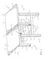
- FIG. 1is a perspective view of a first exemplary embodiment of a table arrangement 1 having multiple tabletops 3 that are independently height adjustable such that a first tabletop 3 a is moveable to a different vertical position than a second tabletop 3 b with a privacy screen element being removed to better illustrate the gap 11 between the tabletops 3 .
- FIG. 2is a perspective view of the first exemplary embodiment of the table arrangement 1 with a tabletop cut away to better illustrate a lower cross bar member extending between the columns 7 and underneath the gap 11 that has slots 21 at its opposite ends.
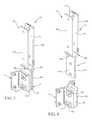
- FIG. 3is a fragmentary enlarged exploded view of the first exemplary embodiment of the table arrangement 1 with a portion of privacy screen connection mechanism for positioning in a slot 21 shown in an exploded view.
- FIG. 3illustrates a first end section of a base member 21 of the first exemplary embodiment of the table arrangement 1 .
- a second end section of the base member 21 of the first exemplary embodiment of the table arrangementwould have a mirror image view as this first end section view shown in FIG. 3 .
- FIG. 4is a view similar to FIG. 3 illustrating the portion of the privacy screen connector 31 positioned in the slot 21 for a first end section of the base member 21 .
- a second end section of the base member 21 of the first exemplary embodiment of the table arrangement 1would have another privacy screen connector 31 positioned in another slot 22 .
- a mirror image view of the first end section view shown in FIG. 4would illustrate this second end privacy screen connector 31 positioned in the other slot 22 .
- FIG. 5is perspective view of an exemplary embodiment of a privacy screen connector 31 that is utilized in the first exemplary embodiment of the table arrangement 1 .
- FIG. 6is a first exploded view of the exemplary embodiment of the privacy screen connector 31 shown in FIG. 5 .
- FIG. 7is a second exploded view of the exemplary embodiment of the privacy screen connector 31 shown in FIG. 5 .
- FIG. 8is a view of the first exemplary embodiment of the table arrangement 1 similar to FIG. 2 with a privacy screen member 71 connected to the base member 21 and one of the tabletops cut away to better illustrate the privacy screen member 71 .
- a table arrangement 1can include an assembly 2 that includes multiple tabletops 3 that are supported by a base 4 .
- the basecan include a plurality of columns 7 and cross-members 9 .
- the columns 7can include a first column and a third column that are positioned to support a first tabletop 3 a and a second column and a fourth column that support a second tabletop 3 b .
- the base 4can also include a base member 21 positioned between the cross-members 9 under the tabletops 3 .
- the table arrangement 1can also include at least one trough that can be connected to the underside of a tabletop 3 or to a cross member that is above the base member 21 that extends between columns 7 so that the trough can be positioned adjacent and below a gap 11 to help route cords, wiring, or other elements that may extend toward or from objects positioned on the tabletop (e.g. power cords for transmission of electricity to that are spaced apart from each other to align with the gap 11 defined between rear edges 3 d of first and second tabletops 3 a and 3 b so that a privacy screen member 71 can extend between troughs and through the gap 11 .
- the table arrangement 1may not include any troughs.
- the first and third columnscan be considered columns of a first set 7 a of columns 7 for principally supporting the first tabletop 3 a .
- the second and fourth columnscan be considered a second set 7 b of columns 7 for principally supporting the second tabletop 3 b.
- a first cross-member 9can extend between a first column 7 that is connected to principally support the first tabletop 3 a and the second column 7 that is positioned to principally support the second tabletop 3 b .
- a second cross-member 9can extend between the third column 7 that is connected to principally support the first tabletop 3 a and the fourth column 7 that is positioned to principally support a second tabletop 3 b .
- the table arrangementcould be considered a workspace arrangement or cubicle type arrangement in which each tabletop 3 could be considered a work surface, a tabletop, a desktop, or a countertop.
- Each of the columns 7can extend vertically along their length from a floor and the cross-members 9 can extend horizontally along their length between the columns to which it is connected.
- the first and second tabletops 3 a and 3 bcan be positioned so that the tabletops' rear edges 3 d are spaced apart from each other to define a gap 11 .
- the columns 7can be positioned so that the columns 7 of the first set 7 a of columns are positioned under the first tabletop 3 a and the columns of the second set 7 b of columns are positioned under the second tabletop 3 b .
- the first set 7 a of columnscan include a pair of columns 7 that are spaced apart from each other and are located on opposite sides (e.g.
- the second set 7 b of columnscan include a pair of columns 7 that are spaced apart from each other and are located on opposite sides (e.g. left and right sides) of the second tabletop 3 b near a middle section of the first tabletop 3 b.
- At least one lower base member 21can be positioned below the gap 11 and between the columns 7 and cross-members 9 to facilitate positioning of at least one privacy screen member 71 (e.g. a privacy screen panel, a partition panel, a partition wall, etc.) that may extend through the gap 11 and above the tabletops 3 (e.g. cubical wall elements, privacy screen elements, etc.).
- at least one privacy screen member 71e.g. a privacy screen panel, a partition panel, a partition wall, etc.
- tabletops 3e.g. cubical wall elements, privacy screen elements, etc.
- the base member 21can extend horizontally from a first side of each tabletop 3 to a second side of each tabletop 3 so that the base member 21 extends between the first and second cross-members 9 a and 9 b that each extends between a respective pair of columns 7 (the first cross-member 9 a being positioned outside of and adjacent the first end of the base member 21 and the second cross-member 9 b being positioned outside of and adjacent the second end of the base member 21 ).
- Each column 7can be configured to facilitate height adjustment of a tabletop 3 .
- the first set 7 a of columnscan be positioned adjacent a middle portion of the first tabletop 3 a on opposite sides of the first tabletop between front and rear sides of the tabletop 3 .
- Each column of the first set 7 a of columnscan include a telescoping member 6 a that is extendable and retractable from a lower member of the column 7 so that actuation of the telescoping member results in height adjustment of the tabletop from a lowermost position to an uppermost position.
- the second set 7 b of columnscan be positioned adjacent a middle portion of the second tabletop 3 b on opposite sides of the second tabletop 3 b between front and rear sides of the tabletop 3 .
- Each column 7 of the second set 7 b of columnscan include a telescoping member 6 a that is extendable and retractable from a lower member of the column 7 so that actuation of the telescoping member results in height adjustment of the tabletop 3 between a lowermost position to an uppermost position.
- Each column 7can include a height adjustment mechanism 6 (e.g. a gas spring, hydraulic spring, etc.) that is connected to the telescoping member 6 a to drive motion of the telescoping member 6 a .
- the height adjustment mechanism 6can be coupled to an actuator to facilitate such height adjustment.
- a usermay utilize the actuator to provide input for actuation of the height adjustment mechanism 6 so that the telescoping members 6 a are vertically moveable for adjusting a position of a tabletop 3 .
- the base member 21can include slots 22 that are positioned adjacent the opposite ends of the base member 21 where each slot 22 is also adjacent a respective one of the cross-members 9 .
- each slot 22is also adjacent a respective one of the cross-members 9 .
- the first slot 22can be positioned adjacent to and in alignment with a first bracket 41 attached to the first cross-member 9 a and the second slot 22 can be positioned adjacent to and in alignment with a second bracket 41 attached to the second cross-member 9 b .
- Each slot 22can communicate with a bottom opening 21 a of the base member 21 .
- the bottom opening 21can be defined by sidewalls 21 s of the base member 21 that extend below a top 21 t of the base member.
- the top 21 t of the base member 21can include an underside surface 21 u and a top surface 21 ts opposite the underside surface 21 u .
- the underside surface 21 ucan help define the shape and size of the bottom opening 21 a .
- the bottom opening 21 acan be defined as a cavity, channel, or recess type opening between the sidewalls 21 s and top 21 t of the base member 21 in some embodiments.
- end walls 21 ewcan also extend downwardly from the top 21 t of the base member to help define a shape of the bottom opening 21 a.
- Brackets 41there can be multiple brackets 41 positioned in the bottom opening 21 a of the base member 21 .
- Each bracket 41can be positioned adjacent a respective cross-member 9 .
- a portion of an end wall 21 ew of the base membercan be positioned between the between the bracket 41 and the cross-member to which that bracket is attached.
- Each bracket 41can be formed via attachment of a first bracket body 41 a and a second bracket body 41 b to an end wall 21 ew of the base member 21 and/or a cross-member 9 via fasteners so that the spaced apart first and second bracket bodies 41 a and 41 b define a gap 43 between the bracket bodies for receipt of a lower portion of a privacy screen connector 31 that may extend below the slot 22 to which the bracket 41 is positioned under and aligned.
- first and second bracket bodies 41 a and 41 b of a first bracket 41can be attached to a first cross-member 9 and/or a first end wall 21 ew and first and second bracket bodies 41 a and 41 b of a second bracket 41 can be attached to a second cross-member 9 and/or a second end wall 21 ew .
- the first bracket 41can be positioned to be under and aligned with a first slot 22 adjacent a first end of the base member 21 and the second bracket 41 can be positioned to be under and aligned with a second slot 22 adjacent a second end of the base member 21 .
- the table arrangementcan include multiple privacy screen connectors 31 to position a privacy screen member 71 on the base member 21 so that a portion of the privacy screen member 71 can extend through the gap 11 and above the tabletops to provide a visible barrier between the first and second tabletops 3 a and 3 b .
- FIGS. 5-7illustrate an example of an embodiment of the privacy screen connector 31 . It should be appreciated that first and second privacy screen connectors 31 can each have the structure of the exemplary embodiment shown in FIGS. 5-7 .
- each privacy screen connector 31can extend downwardly from a slot 22 of the base member 21 to the bracket to which it is attached.
- An upper portion of each privacy screen connectorcan extend above the slot 22 and be configured to receive and retain a respective portion of the privacy screen member 71 on the base member 21 and/or adjacent the base member 21 .
- the first privacy screen connector 31can have an upper portion 33 that is configured to retain a first portion of a privacy screen member 71 and the second privacy screen connector 31 can have an upper portion 33 that is configured to retain a second portion of a privacy screen member 71 .
- the first and second portions of the privacy screen member 71can be portions of the same member that are spaced apart from each other along the length of the privacy screen member 71 .
- each privacy screen connector 31can include an upper portion 33 and a lower end portion 37 that are integrally attached to each other such that an upper slot with a top mouth 51 a in communication with a channel 35 is defined between upper spaced apart upper bodies 33 a and 33 b of the upper portion 33 .
- the top mouth 51 acan be defined for receiving a portion of a privacy screen member 71 .
- the channel 35 in communication with the top mouth 51 acan be configured for retaining a portion of a lower end or lower side of the privacy screen member 71 .
- the upper portion 33 of the privacy screen connector 31can be above the slot 22 to which that privacy screen connector is to be positioned.
- the upper portion 33can define a top portion of the privacy screen connector 31 that extends above the slot 22 in which that privacy screen connector 31 is positioned.
- the lower end portion 37 of the privacy screen connector 31can extend downwardly from the slot 22 (or adjacent the slot 22 ) to within the gap 43 for being attached to the bracket 41 via fasteners (e.g. bolts, screws, etc.).
- the lower end portion 37can define a bottom end portion of the privacy screen connector 31 .
- Each side of the privacy screen connector 31can be defined by an integrally molded or cast metal structure or polymeric structure. These structures may be spaced apart from each other to define the upper mouth 51 a and channel 35 of the upper portion 33 and contact each other at their lower portions to define the lower end portion 37 to be narrower than the channel 35 that receives and holds the privacy screen member 71 for insertion through a slot 22 and a bracket gap 43 .
- Each integral cast or formed membercan have an intermediate angled portion to define this widening/narrowing region.
- a first member 61 of the privacy screen connector 31can define a first upper body 33 a , a first lower body 37 a and a first widening/narrowing body 36 a that is a first intermediate body positioned between the first upper body 33 a and first lower body 37 a .
- the second member 62 of the privacy screen connector 31can define a second upper body 33 b , a second lower body 37 b and a second widening/narrowing body 36 b that is a second intermediate body between the second upper body 33 b and second lower body 37 b.
- the first member 61 of the privacy screen connector 31can be a unitary structure in which the first upper body 33 a , first lower body 37 a and the first widening/narrowing body 36 a that is between the first upper body 33 a and first lower body 37 a are portions of an integral, unitary structure (e.g. a metal structure formed as a single, unitary piece, a polymeric structure molded or otherwise formed as a single, unitary piece, etc.).
- an integral, unitary structuree.g. a metal structure formed as a single, unitary piece, a polymeric structure molded or otherwise formed as a single, unitary piece, etc.
- the second member 62 of the privacy screen connector 31can be a unitary structure in which the second upper body 33 b , second lower body 37 b and the second widening/narrowing body 36 b that is between the second upper body 33 b and second lower body 37 b are portions of an integral, unitary structure (e.g. a metal structure formed as a single, unitary piece, a polymeric structure molded or otherwise formed as a single, unitary piece, etc.).
- Fastenerscan be utilized to connect the first member 61 of the privacy screen connector to the second member 62 of the privacy screen connector.
- the entire body and structure of each privacy screen connector 31can be formed as a unitary structure (e.g. via casting, molding, and/or welding).
- the privacy screen connectors 31 and brackets 41can be utilized to provide a connection of the privacy screen member 71 at opposite ends of the lower base member 21 via spaced apart slots 22 .
- This connectioncan permit the privacy screen member 71 to be inserted into the channels 35 of the privacy screen connectors 31 via the top mouths 51 a of those connectors 31 so that screen rigidity can be provided.
- one or more fasteners 81can be inserted into the privacy screen connectors 31 to pass through the privacy screen member 71 to help retain the privacy screen member 71 .
- Each fastener 81can extend from a hole defined in the first upper body 33 a to a hole defined in the second upper body 33 b so that the fastener 81 is positionable in the channel and is passable through the privacy screen member 71 .
- Each privacy screen connector 31can be configured to utilize at least one such fastener 81 .
- such fasteners 81may not be used and the privacy screen member 71 can be retained via an interference fit between the first and second upper bodies 33 a and 33 b of each privacy screen connector 31 or otherwise being physically retained between these upper bodies 33 a and 33 b (e.g. a looser retention than a tight interference fit, etc.).
- the rigid support of the privacy screen member 71can permit a relatively tall privacy screen member 71 to be mounted to extend through the gap 11 between tabletops 3 and provide a desired height above the tabletops to accommodate height adjustment of the tabletops while still providing a desired level of privacy protection to the workers who may work at their respective tabletops 3 .
- the height to which the privacy screen member 71 can extend above the tabletops 3can be facilitated via the privacy screen connection mechanism that includes the spaced apart privacy screen connectors 31 and brackets 41 to which they are connected and slots 22 defined in the base member 21 as well as the top surface 21 ts of the base member 21 on which a lower edge of the privacy screen member may abut or be adjacent.
- embodiments of the table arrangement 1 and connection mechanisms used in that embodimentmay be configured to meet different design criteria.
- the tabletops 3may not be height adjustable or may be height adjustable and also be pivotable or otherwise moveable.
- the bottom of each column 7may be configured to contact a floor, be connected to a foot for stationary positioning on the floor, or be connected to a rollable wheel or castor.
- the base member 21can include at least one first end wall 21 ew and at least one second end wall 21 ew on opposite ends of the base member that extend below the top 21 t between opposite sidewalls 21 s that extend below the top 21 t at opposite front and rear sides of the base member 21 .
- the sidewalls 21 scan extend along a length L of the base member 21 and the end walls 21 ew can extend along the entire width W of the base member 21 .
- the end walls 21 ewmay not extend along the entire width W of the base member to define a particular type of shape or define one or more apertures for facilitating a connection of a bracket 41 to a cross-member 9 .
- the end walls 21 ewmay not be present and the first and second bodies 41 a and 41 b of the bracket 41 may be attached directly to a cross-member 9 without the end wall 21 ew being between the cross-member 9 and the bracket 41 .
- each of the privacy screen connectors 31can be adjusted to meet a particular set of design objectives (e.g. accommodation of a particular sized and shaped privacy screen member 71 , particular size and shape of gap 11 or tabletop 3 , particular size and shape of bracket 41 and/or cross-member 9 , etc.). Therefore, while certain exemplary embodiments of the table arrangement, privacy screen connection mechanisms used in the table arrangement and methods of making and using the same have been discussed and illustrated herein, it is to be distinctly understood that the invention is not limited thereto but may be otherwise variously embodied and practiced within the scope of the following claims.
Landscapes
- Combinations Of Kitchen Furniture (AREA)
- Tables And Desks Characterized By Structural Shape (AREA)
Abstract
Description
Claims (20)
Priority Applications (1)
| Application Number | Priority Date | Filing Date | Title |
|---|---|---|---|
| US16/190,202US10390611B2 (en) | 2017-11-15 | 2018-11-14 | Privacy screen table connection mechanism |
Applications Claiming Priority (2)
| Application Number | Priority Date | Filing Date | Title |
|---|---|---|---|
| US201762586380P | 2017-11-15 | 2017-11-15 | |
| US16/190,202US10390611B2 (en) | 2017-11-15 | 2018-11-14 | Privacy screen table connection mechanism |
Publications (2)
| Publication Number | Publication Date |
|---|---|
| US20190142155A1 US20190142155A1 (en) | 2019-05-16 |
| US10390611B2true US10390611B2 (en) | 2019-08-27 |
Family
ID=66431173
Family Applications (1)
| Application Number | Title | Priority Date | Filing Date |
|---|---|---|---|
| US16/190,202ActiveUS10390611B2 (en) | 2017-11-15 | 2018-11-14 | Privacy screen table connection mechanism |
Country Status (1)
| Country | Link |
|---|---|
| US (1) | US10390611B2 (en) |
Cited By (14)
| Publication number | Priority date | Publication date | Assignee | Title |
|---|---|---|---|---|
| USD868515S1 (en)* | 2018-03-19 | 2019-12-03 | Landscape Forms, Inc. | Table with luminaire |
| USD868516S1 (en)* | 2018-03-19 | 2019-12-03 | Landscape Forms, Inc. | Table |
| USD906561S1 (en) | 2018-10-27 | 2020-12-29 | Landscape Forms, Inc. | Luminaire |
| US20210219746A1 (en)* | 2018-11-20 | 2021-07-22 | Target Brands, Inc. | Tiered display unit |
| US11291299B2 (en)* | 2020-05-08 | 2022-04-05 | Charles Isgar | Retractable self-sanitizing divider assembly |
| US11549537B2 (en) | 2020-06-19 | 2023-01-10 | Knoll, Inc. | Article of furniture and method of installing same |
| US11672333B2 (en) | 2020-09-09 | 2023-06-13 | Ronald Giery | Flip top table with a nested leg assembly |
| USD1006383S1 (en) | 2021-08-16 | 2023-11-28 | AMQ Solutions, LLC | Mobile cart with shelves |
| USD1006379S1 (en) | 2021-08-16 | 2023-11-28 | AMQ Solutions, LLC | Mobile cart with screen |
| USD1007094S1 (en) | 2021-08-16 | 2023-12-05 | AMQ Solutions, LLC | Mobile cart with storage unit |
| US11877646B2 (en) | 2021-07-12 | 2024-01-23 | Knoll, Inc. | Work surface attachment mechanism, article of furniture, and method of making the article of furniture |
| US11944208B2 (en) | 2021-06-14 | 2024-04-02 | Knoll, Inc. | Chair and method of making the chair |
| US12016455B2 (en) | 2020-06-19 | 2024-06-25 | Knoll, Inc. | Work surface height adjustment stop apparatus and method of utilizing same |
| US20240268552A1 (en)* | 2023-02-10 | 2024-08-15 | Knoll, Inc. | Channel assembly to reduce worksurface sag |
Families Citing this family (6)
| Publication number | Priority date | Publication date | Assignee | Title |
|---|---|---|---|---|
| US10758038B2 (en) | 2018-05-29 | 2020-09-01 | Knoll, Inc. | Article of furniture and method of using the same |
| US10638833B1 (en)* | 2018-08-10 | 2020-05-05 | Bernard Brucha | System and method for a workstation power trough |
| USD944547S1 (en)* | 2020-08-31 | 2022-03-01 | R.A.S. Developments, Llc | Partition apparatus |
| US11969081B2 (en) | 2020-10-28 | 2024-04-30 | Quint Workspaces Llc | Connection assembly for connecting a support member to a work surface and corresponding method |
| US11877649B1 (en)* | 2022-07-22 | 2024-01-23 | Brand Villages, Llc | Desks with multiple adjustable top panels |
| CN115778099B (en)* | 2022-12-29 | 2024-01-05 | 绍兴市耐特驱动科技有限公司 | Peep-proof desk for teaching examination |
Citations (50)
| Publication number | Priority date | Publication date | Assignee | Title |
|---|---|---|---|---|
| US905965A (en)* | 1907-02-19 | 1908-12-08 | Edward Darling Wilde | Table. |
| US974340A (en)* | 1909-10-18 | 1910-11-01 | John F Bebb | Extension-shelf for writing-tables. |
| US2688525A (en)* | 1952-06-05 | 1954-09-07 | Remington Rand Inc | Utility counter-desk |
| US2694614A (en)* | 1950-12-29 | 1954-11-16 | Clarence H Dent | Multiple desk unit |
| US2821450A (en)* | 1956-08-09 | 1958-01-28 | Knoll Associates | Desk structure |
| US2942924A (en)* | 1957-10-28 | 1960-06-28 | Chester A Stangert | Furniture |
| US3069795A (en) | 1959-10-29 | 1962-12-25 | Aaron L Lieberman | Photographic slide mount |
| US3083417A (en)* | 1959-05-18 | 1963-04-02 | Indiana University Foundation | Booth structure |
| US3297208A (en) | 1965-06-23 | 1967-01-10 | Rexall Drug Chemical | Container spout, with axially movable, horizontally swingable pouring extension, and a captive closure |
| US3413593A (en) | 1967-11-03 | 1968-11-26 | Joseph K. Schaefer | Isolated electrical terminal connection |
| US3685465A (en)* | 1970-05-29 | 1972-08-22 | Carlo Haumer | Modular furniture structures |
| US4314700A (en)* | 1980-10-03 | 1982-02-09 | Dylag Kenneth C | Card counting prevention apparatus for blackjack |
| US4604955A (en) | 1981-10-03 | 1986-08-12 | Willy Fleischer Metallwarenfabrik Gmbh & Co. | Height-adjustable table for work places with video screen |
| US4763581A (en)* | 1986-12-15 | 1988-08-16 | Midland Manufacturing Corp. | Multi-station carrel unit |
| US4870908A (en)* | 1988-07-05 | 1989-10-03 | Westinghouse Electric Corp. | Office space dividing system |
| US5224429A (en) | 1991-04-17 | 1993-07-06 | Haworth, Inc. | Height adjustable table |
| US5408940A (en) | 1992-06-25 | 1995-04-25 | Winchell; Paul W. | Adjustable height work surface wtih rack and pinion arrangements |
| US5562052A (en) | 1995-06-02 | 1996-10-08 | Haworth, Inc. | Height-adjustable table |
| US5598789A (en) | 1994-03-15 | 1997-02-04 | Knoll, Inc. | Vertically adjustable table |
| US5706739A (en) | 1996-12-12 | 1998-01-13 | Ergotech (1993) Inc. | Height adjustable counterbalance workstation |
| US5715761A (en) | 1995-08-01 | 1998-02-10 | Knoll, Inc. | Article of furniture including a leg having wire management capabilities |
| US5881979A (en) | 1997-06-04 | 1999-03-16 | Knoll, Inc. | Telescoping leveler |
| US5941182A (en) | 1997-05-29 | 1999-08-24 | Knoll, Inc. | Self-braking height adjustment mechanism |
| US6029587A (en) | 1998-06-05 | 2000-02-29 | Knoll, Inc. | Offset support leg for an adjustable height desk |
| US6164217A (en) | 1996-11-30 | 2000-12-26 | Mad Design Co. Ltd. | Folding table |
| US20020092443A1 (en)* | 2001-01-18 | 2002-07-18 | Grant Walter S. | Collapsible voting booth |
| US6536357B1 (en) | 2000-06-01 | 2003-03-25 | Formway Furniture Limited | Height adjustable table |
| US6546880B2 (en) | 1999-06-09 | 2003-04-15 | Baker Manufacturing Company | Height adjustable table |
| US6637352B1 (en) | 1999-08-23 | 2003-10-28 | Wilkhahn Wilkening + Hahne Gmbh + Co. | Table with pivotable table-top |
| US6845723B2 (en) | 2002-10-31 | 2005-01-25 | Hon Technology Inc. | Folding and tilting table |
| US7066098B2 (en) | 2004-05-14 | 2006-06-27 | Hni Technologies Inc. | Nesting table with controlled pivoting movement |
| US20080196635A1 (en) | 2007-02-19 | 2008-08-21 | Alessandro Piretti | Nesting and folding table |
| US7614351B2 (en) | 2001-06-15 | 2009-11-10 | Pro-Cord S.P.A. | Folding table |
| US7712422B2 (en) | 2006-07-19 | 2010-05-11 | Sico Incorporated | Folding table |
| US7845290B2 (en) | 2005-04-13 | 2010-12-07 | Pro-Cord Spa | Nesting and folding table |
| US7878128B2 (en) | 2001-10-02 | 2011-02-01 | Steelcase Development Corporation | Pivotable board provided with legs |
| US8051784B2 (en) | 2008-05-14 | 2011-11-08 | Chuan-Fu Hsu | Folding device for a tabletop |
| US8056489B2 (en) | 2005-11-30 | 2011-11-15 | Linak A/S | Telescopic column, especially for height adjustable tables |
| US8091488B2 (en) | 2007-11-07 | 2012-01-10 | Berco Industries, Inc. | Flip top mechanism for table with nesting capabilities |
| US8171863B2 (en) | 2008-02-14 | 2012-05-08 | DSA International, Inc. | Flip-top table mechanism |
| US20120126072A1 (en) | 2010-11-23 | 2012-05-24 | Hans Pettersson | Height-adjustable table stand |
| US8256359B1 (en) | 2007-01-31 | 2012-09-04 | Baker Manufacturing Company, Inc. | Height adjustable table |
| US8359983B2 (en) | 2011-06-02 | 2013-01-29 | Halcon Inc. | Adjustable table apparatus and method |
| US20130204438A1 (en) | 2012-02-07 | 2013-08-08 | Kih-Utveckling Ab | Control of a height adjustable piece of furniture |
| US8578864B2 (en) | 2008-02-14 | 2013-11-12 | DSA International, Inc. | Removable attachment bar for a flip-top table |
| US8667909B2 (en) | 2011-06-03 | 2014-03-11 | Knoll, Inc. | Adjustable attachment device for furniture |
| US20140312754A1 (en)* | 2013-03-15 | 2014-10-23 | Herman Miller, Inc. | Worksurface assembly having cantilevered, vertically adjustable worksurfaces |
| US8869715B2 (en) | 2009-06-09 | 2014-10-28 | Ditto Sales, Inc. | Tilting tabletop mechanism |
| US9265340B2 (en) | 2013-10-28 | 2016-02-23 | Knoll, Inc. | Article of furniture and method of stacking the same |
| US9585468B2 (en) | 2014-06-09 | 2017-03-07 | Knoll, Inc. | Cord management system for furniture |
- 2018
- 2018-11-14USUS16/190,202patent/US10390611B2/enactiveActive
Patent Citations (51)
| Publication number | Priority date | Publication date | Assignee | Title |
|---|---|---|---|---|
| US905965A (en)* | 1907-02-19 | 1908-12-08 | Edward Darling Wilde | Table. |
| US974340A (en)* | 1909-10-18 | 1910-11-01 | John F Bebb | Extension-shelf for writing-tables. |
| US2694614A (en)* | 1950-12-29 | 1954-11-16 | Clarence H Dent | Multiple desk unit |
| US2688525A (en)* | 1952-06-05 | 1954-09-07 | Remington Rand Inc | Utility counter-desk |
| US2821450A (en)* | 1956-08-09 | 1958-01-28 | Knoll Associates | Desk structure |
| US2942924A (en)* | 1957-10-28 | 1960-06-28 | Chester A Stangert | Furniture |
| US3083417A (en)* | 1959-05-18 | 1963-04-02 | Indiana University Foundation | Booth structure |
| US3069795A (en) | 1959-10-29 | 1962-12-25 | Aaron L Lieberman | Photographic slide mount |
| US3297208A (en) | 1965-06-23 | 1967-01-10 | Rexall Drug Chemical | Container spout, with axially movable, horizontally swingable pouring extension, and a captive closure |
| US3413593A (en) | 1967-11-03 | 1968-11-26 | Joseph K. Schaefer | Isolated electrical terminal connection |
| US3685465A (en)* | 1970-05-29 | 1972-08-22 | Carlo Haumer | Modular furniture structures |
| US4314700A (en)* | 1980-10-03 | 1982-02-09 | Dylag Kenneth C | Card counting prevention apparatus for blackjack |
| US4604955A (en) | 1981-10-03 | 1986-08-12 | Willy Fleischer Metallwarenfabrik Gmbh & Co. | Height-adjustable table for work places with video screen |
| US4763581A (en)* | 1986-12-15 | 1988-08-16 | Midland Manufacturing Corp. | Multi-station carrel unit |
| US4870908A (en)* | 1988-07-05 | 1989-10-03 | Westinghouse Electric Corp. | Office space dividing system |
| US5224429A (en) | 1991-04-17 | 1993-07-06 | Haworth, Inc. | Height adjustable table |
| US5408940A (en) | 1992-06-25 | 1995-04-25 | Winchell; Paul W. | Adjustable height work surface wtih rack and pinion arrangements |
| US5598789A (en) | 1994-03-15 | 1997-02-04 | Knoll, Inc. | Vertically adjustable table |
| US5562052A (en) | 1995-06-02 | 1996-10-08 | Haworth, Inc. | Height-adjustable table |
| US6389988B1 (en) | 1995-08-01 | 2002-05-21 | Knoll, Inc. | Article of furniture including a leg having wire management capabilities |
| US5715761A (en) | 1995-08-01 | 1998-02-10 | Knoll, Inc. | Article of furniture including a leg having wire management capabilities |
| US6164217A (en) | 1996-11-30 | 2000-12-26 | Mad Design Co. Ltd. | Folding table |
| US5706739A (en) | 1996-12-12 | 1998-01-13 | Ergotech (1993) Inc. | Height adjustable counterbalance workstation |
| US5941182A (en) | 1997-05-29 | 1999-08-24 | Knoll, Inc. | Self-braking height adjustment mechanism |
| US5881979A (en) | 1997-06-04 | 1999-03-16 | Knoll, Inc. | Telescoping leveler |
| US6029587A (en) | 1998-06-05 | 2000-02-29 | Knoll, Inc. | Offset support leg for an adjustable height desk |
| US6546880B2 (en) | 1999-06-09 | 2003-04-15 | Baker Manufacturing Company | Height adjustable table |
| US6637352B1 (en) | 1999-08-23 | 2003-10-28 | Wilkhahn Wilkening + Hahne Gmbh + Co. | Table with pivotable table-top |
| US6536357B1 (en) | 2000-06-01 | 2003-03-25 | Formway Furniture Limited | Height adjustable table |
| US20020092443A1 (en)* | 2001-01-18 | 2002-07-18 | Grant Walter S. | Collapsible voting booth |
| US7614351B2 (en) | 2001-06-15 | 2009-11-10 | Pro-Cord S.P.A. | Folding table |
| US7878128B2 (en) | 2001-10-02 | 2011-02-01 | Steelcase Development Corporation | Pivotable board provided with legs |
| US6845723B2 (en) | 2002-10-31 | 2005-01-25 | Hon Technology Inc. | Folding and tilting table |
| US7066098B2 (en) | 2004-05-14 | 2006-06-27 | Hni Technologies Inc. | Nesting table with controlled pivoting movement |
| US7845290B2 (en) | 2005-04-13 | 2010-12-07 | Pro-Cord Spa | Nesting and folding table |
| US8056489B2 (en) | 2005-11-30 | 2011-11-15 | Linak A/S | Telescopic column, especially for height adjustable tables |
| US7712422B2 (en) | 2006-07-19 | 2010-05-11 | Sico Incorporated | Folding table |
| US8256359B1 (en) | 2007-01-31 | 2012-09-04 | Baker Manufacturing Company, Inc. | Height adjustable table |
| US20080196635A1 (en) | 2007-02-19 | 2008-08-21 | Alessandro Piretti | Nesting and folding table |
| US8091488B2 (en) | 2007-11-07 | 2012-01-10 | Berco Industries, Inc. | Flip top mechanism for table with nesting capabilities |
| US8171863B2 (en) | 2008-02-14 | 2012-05-08 | DSA International, Inc. | Flip-top table mechanism |
| US8578864B2 (en) | 2008-02-14 | 2013-11-12 | DSA International, Inc. | Removable attachment bar for a flip-top table |
| US8051784B2 (en) | 2008-05-14 | 2011-11-08 | Chuan-Fu Hsu | Folding device for a tabletop |
| US8869715B2 (en) | 2009-06-09 | 2014-10-28 | Ditto Sales, Inc. | Tilting tabletop mechanism |
| US20120126072A1 (en) | 2010-11-23 | 2012-05-24 | Hans Pettersson | Height-adjustable table stand |
| US8359983B2 (en) | 2011-06-02 | 2013-01-29 | Halcon Inc. | Adjustable table apparatus and method |
| US8667909B2 (en) | 2011-06-03 | 2014-03-11 | Knoll, Inc. | Adjustable attachment device for furniture |
| US20130204438A1 (en) | 2012-02-07 | 2013-08-08 | Kih-Utveckling Ab | Control of a height adjustable piece of furniture |
| US20140312754A1 (en)* | 2013-03-15 | 2014-10-23 | Herman Miller, Inc. | Worksurface assembly having cantilevered, vertically adjustable worksurfaces |
| US9265340B2 (en) | 2013-10-28 | 2016-02-23 | Knoll, Inc. | Article of furniture and method of stacking the same |
| US9585468B2 (en) | 2014-06-09 | 2017-03-07 | Knoll, Inc. | Cord management system for furniture |
Cited By (15)
| Publication number | Priority date | Publication date | Assignee | Title |
|---|---|---|---|---|
| USD868515S1 (en)* | 2018-03-19 | 2019-12-03 | Landscape Forms, Inc. | Table with luminaire |
| USD868516S1 (en)* | 2018-03-19 | 2019-12-03 | Landscape Forms, Inc. | Table |
| USD906561S1 (en) | 2018-10-27 | 2020-12-29 | Landscape Forms, Inc. | Luminaire |
| US11576503B2 (en)* | 2018-11-20 | 2023-02-14 | Target Brands, Inc. | Tiered display unit |
| US20210219746A1 (en)* | 2018-11-20 | 2021-07-22 | Target Brands, Inc. | Tiered display unit |
| US11291299B2 (en)* | 2020-05-08 | 2022-04-05 | Charles Isgar | Retractable self-sanitizing divider assembly |
| US11549537B2 (en) | 2020-06-19 | 2023-01-10 | Knoll, Inc. | Article of furniture and method of installing same |
| US12016455B2 (en) | 2020-06-19 | 2024-06-25 | Knoll, Inc. | Work surface height adjustment stop apparatus and method of utilizing same |
| US11672333B2 (en) | 2020-09-09 | 2023-06-13 | Ronald Giery | Flip top table with a nested leg assembly |
| US11944208B2 (en) | 2021-06-14 | 2024-04-02 | Knoll, Inc. | Chair and method of making the chair |
| US11877646B2 (en) | 2021-07-12 | 2024-01-23 | Knoll, Inc. | Work surface attachment mechanism, article of furniture, and method of making the article of furniture |
| USD1006383S1 (en) | 2021-08-16 | 2023-11-28 | AMQ Solutions, LLC | Mobile cart with shelves |
| USD1006379S1 (en) | 2021-08-16 | 2023-11-28 | AMQ Solutions, LLC | Mobile cart with screen |
| USD1007094S1 (en) | 2021-08-16 | 2023-12-05 | AMQ Solutions, LLC | Mobile cart with storage unit |
| US20240268552A1 (en)* | 2023-02-10 | 2024-08-15 | Knoll, Inc. | Channel assembly to reduce worksurface sag |
Also Published As
| Publication number | Publication date |
|---|---|
| US20190142155A1 (en) | 2019-05-16 |
Similar Documents
| Publication | Publication Date | Title |
|---|---|---|
| US10390611B2 (en) | Privacy screen table connection mechanism | |
| US11812848B2 (en) | Furniture system | |
| US6824220B1 (en) | Modular furniture retaining system | |
| US6167579B1 (en) | Furniture system | |
| US10383435B1 (en) | Desking arrangement | |
| US9750344B2 (en) | Table benching apparatus and methods of using the same | |
| US8234983B2 (en) | Post and beam furniture construction | |
| US10722028B2 (en) | Table connection mechanism and method of using the same | |
| CA1067557A (en) | End panel support system | |
| US6976732B2 (en) | Convertible furniture system comprised of modular convertible box frames and methods of forming various furniture configurations therefrom | |
| KR20010012577A (en) | Freestanding furniture defining office with adjustable footprint | |
| CA3051211A1 (en) | Adjustable workstation with cable management | |
| WO2016175241A1 (en) | Top-panel-equipped furniture and furniture system | |
| EP2166170A1 (en) | A modular furniture system | |
| US20070262685A1 (en) | Post and beam furniture construction | |
| US10470560B2 (en) | Slidable furniture with in-wall mounting system | |
| WO2006029895A1 (en) | Desk system or office furniture | |
| JPH0522Y2 (en) | ||
| JP7501218B2 (en) | desk | |
| CA2940479C (en) | Slidable furniture with in-wall mounting system | |
| EP2022368B1 (en) | Modular console for computers and the like | |
| JP7471050B2 (en) | Lift table | |
| JP7454351B2 (en) | Beam for mounting parts and table equipped with it | |
| JP2007289354A (en) | Reconfigurable desk with shelf | |
| JP2016016240A (en) | furniture |
Legal Events
| Date | Code | Title | Description |
|---|---|---|---|
| FEPP | Fee payment procedure | Free format text:ENTITY STATUS SET TO UNDISCOUNTED (ORIGINAL EVENT CODE: BIG.); ENTITY STATUS OF PATENT OWNER: LARGE ENTITY | |
| AS | Assignment | Owner name:KNOLL, INC., PENNSYLVANIA Free format text:ASSIGNMENT OF ASSIGNORS INTEREST;ASSIGNOR:LEE, JEFFREY P.;REEL/FRAME:047942/0640 Effective date:20181219 | |
| STPP | Information on status: patent application and granting procedure in general | Free format text:NOTICE OF ALLOWANCE MAILED -- APPLICATION RECEIVED IN OFFICE OF PUBLICATIONS | |
| STPP | Information on status: patent application and granting procedure in general | Free format text:PUBLICATIONS -- ISSUE FEE PAYMENT VERIFIED | |
| STCF | Information on status: patent grant | Free format text:PATENTED CASE | |
| AS | Assignment | Owner name:BANK OF AMERICA, N.A., AS ADMINISTRATIVE AGENT, NO Free format text:NOTICE OF GRANT OF SECURITY INTEREST IN PATENTS;ASSIGNOR:KNOLL, INC.;REEL/FRAME:050168/0771 Effective date:20180123 Owner name:BANK OF AMERICA, N.A., AS ADMINISTRATIVE AGENT, NORTH CAROLINA Free format text:NOTICE OF GRANT OF SECURITY INTEREST IN PATENTS;ASSIGNOR:KNOLL, INC.;REEL/FRAME:050168/0771 Effective date:20180123 | |
| AS | Assignment | Owner name:GOLDMAN SACHS BANK USA, AS COLLATERAL AGENT, NEW YORK Free format text:SECURITY INTEREST;ASSIGNOR:KNOLL, INC.;REEL/FRAME:057649/0828 Effective date:20210719 | |
| AS | Assignment | Owner name:KNOLL, INC., PENNSYLVANIA Free format text:TERMINATION AND RELEASE OF SECURITY INTEREST IN PATENTS;ASSIGNOR:BANK OF AMERICA, N.A., AS ADMINISTRATIVE AGENT;REEL/FRAME:056924/0159 Effective date:20210719 | |
| MAFP | Maintenance fee payment | Free format text:PAYMENT OF MAINTENANCE FEE, 4TH YEAR, LARGE ENTITY (ORIGINAL EVENT CODE: M1551); ENTITY STATUS OF PATENT OWNER: LARGE ENTITY Year of fee payment:4 | |
| AS | Assignment | Owner name:WELLS FARGO BANK, NATIONAL ASSOCIATION, NORTH CAROLINA Free format text:ASSIGNMENT OF SECURITY INTEREST IN PATENT COLLATERAL;ASSIGNOR:GOLDMAN SACHS BANK USA;REEL/FRAME:072342/0380 Effective date:20250807 |