US10390182B2 - Real-time location system (RTLS) having tags, beacons and bridges, that uses a combination of motion detection and RSSI measurements to determine room-location of the tags - Google Patents
Real-time location system (RTLS) having tags, beacons and bridges, that uses a combination of motion detection and RSSI measurements to determine room-location of the tagsDownload PDFInfo
- Publication number
- US10390182B2 US10390182B2US16/214,890US201816214890AUS10390182B2US 10390182 B2US10390182 B2US 10390182B2US 201816214890 AUS201816214890 AUS 201816214890AUS 10390182 B2US10390182 B2US 10390182B2
- Authority
- US
- United States
- Prior art keywords
- location
- tag
- motion
- room
- tags
- Prior art date
- Legal status (The legal status is an assumption and is not a legal conclusion. Google has not performed a legal analysis and makes no representation as to the accuracy of the status listed.)
- Active
Links
Images


Classifications
- H—ELECTRICITY
- H04—ELECTRIC COMMUNICATION TECHNIQUE
- H04W—WIRELESS COMMUNICATION NETWORKS
- H04W4/00—Services specially adapted for wireless communication networks; Facilities therefor
- H04W4/02—Services making use of location information
- H04W4/029—Location-based management or tracking services
- G—PHYSICS
- G01—MEASURING; TESTING
- G01S—RADIO DIRECTION-FINDING; RADIO NAVIGATION; DETERMINING DISTANCE OR VELOCITY BY USE OF RADIO WAVES; LOCATING OR PRESENCE-DETECTING BY USE OF THE REFLECTION OR RERADIATION OF RADIO WAVES; ANALOGOUS ARRANGEMENTS USING OTHER WAVES
- G01S5/00—Position-fixing by co-ordinating two or more direction or position line determinations; Position-fixing by co-ordinating two or more distance determinations
- G01S5/0009—Transmission of position information to remote stations
- G01S5/0018—Transmission from mobile station to base station
- G01S5/0036—Transmission from mobile station to base station of measured values, i.e. measurement on mobile and position calculation on base station
- G—PHYSICS
- G01—MEASURING; TESTING
- G01S—RADIO DIRECTION-FINDING; RADIO NAVIGATION; DETERMINING DISTANCE OR VELOCITY BY USE OF RADIO WAVES; LOCATING OR PRESENCE-DETECTING BY USE OF THE REFLECTION OR RERADIATION OF RADIO WAVES; ANALOGOUS ARRANGEMENTS USING OTHER WAVES
- G01S5/00—Position-fixing by co-ordinating two or more direction or position line determinations; Position-fixing by co-ordinating two or more distance determinations
- G01S5/02—Position-fixing by co-ordinating two or more direction or position line determinations; Position-fixing by co-ordinating two or more distance determinations using radio waves
- G01S5/14—Determining absolute distances from a plurality of spaced points of known location
- G—PHYSICS
- G08—SIGNALLING
- G08B—SIGNALLING OR CALLING SYSTEMS; ORDER TELEGRAPHS; ALARM SYSTEMS
- G08B13/00—Burglar, theft or intruder alarms
- G08B13/22—Electrical actuation
- G08B13/24—Electrical actuation by interference with electromagnetic field distribution
- G08B13/2402—Electronic Article Surveillance [EAS], i.e. systems using tags for detecting removal of a tagged item from a secure area, e.g. tags for detecting shoplifting
- G08B13/2451—Specific applications combined with EAS
- G08B13/2462—Asset location systems combined with EAS
- H—ELECTRICITY
- H04—ELECTRIC COMMUNICATION TECHNIQUE
- H04W—WIRELESS COMMUNICATION NETWORKS
- H04W4/00—Services specially adapted for wireless communication networks; Facilities therefor
- H04W4/02—Services making use of location information
- H—ELECTRICITY
- H04—ELECTRIC COMMUNICATION TECHNIQUE
- H04W—WIRELESS COMMUNICATION NETWORKS
- H04W4/00—Services specially adapted for wireless communication networks; Facilities therefor
- H04W4/02—Services making use of location information
- H04W4/025—Services making use of location information using location based information parameters
- H04W4/027—Services making use of location information using location based information parameters using movement velocity, acceleration information
- H—ELECTRICITY
- H04—ELECTRIC COMMUNICATION TECHNIQUE
- H04W—WIRELESS COMMUNICATION NETWORKS
- H04W4/00—Services specially adapted for wireless communication networks; Facilities therefor
- H04W4/30—Services specially adapted for particular environments, situations or purposes
- H04W4/33—Services specially adapted for particular environments, situations or purposes for indoor environments, e.g. buildings
- H—ELECTRICITY
- H04—ELECTRIC COMMUNICATION TECHNIQUE
- H04W—WIRELESS COMMUNICATION NETWORKS
- H04W4/00—Services specially adapted for wireless communication networks; Facilities therefor
- H04W4/80—Services using short range communication, e.g. near-field communication [NFC], radio-frequency identification [RFID] or low energy communication
- G—PHYSICS
- G01—MEASURING; TESTING
- G01S—RADIO DIRECTION-FINDING; RADIO NAVIGATION; DETERMINING DISTANCE OR VELOCITY BY USE OF RADIO WAVES; LOCATING OR PRESENCE-DETECTING BY USE OF THE REFLECTION OR RERADIATION OF RADIO WAVES; ANALOGOUS ARRANGEMENTS USING OTHER WAVES
- G01S2205/00—Position-fixing by co-ordinating two or more direction or position line determinations; Position-fixing by co-ordinating two or more distance determinations
- G01S2205/01—Position-fixing by co-ordinating two or more direction or position line determinations; Position-fixing by co-ordinating two or more distance determinations specially adapted for specific applications
- H04L67/18—
- H—ELECTRICITY
- H04—ELECTRIC COMMUNICATION TECHNIQUE
- H04L—TRANSMISSION OF DIGITAL INFORMATION, e.g. TELEGRAPHIC COMMUNICATION
- H04L67/00—Network arrangements or protocols for supporting network services or applications
- H04L67/50—Network services
- H04L67/52—Network services specially adapted for the location of the user terminal
- H—ELECTRICITY
- H04—ELECTRIC COMMUNICATION TECHNIQUE
- H04W—WIRELESS COMMUNICATION NETWORKS
- H04W4/00—Services specially adapted for wireless communication networks; Facilities therefor
- H04W4/90—Services for handling of emergency or hazardous situations, e.g. earthquake and tsunami warning systems [ETWS]
- H—ELECTRICITY
- H04—ELECTRIC COMMUNICATION TECHNIQUE
- H04W—WIRELESS COMMUNICATION NETWORKS
- H04W8/00—Network data management
- H04W8/005—Discovery of network devices, e.g. terminals
- H—ELECTRICITY
- H04—ELECTRIC COMMUNICATION TECHNIQUE
- H04W—WIRELESS COMMUNICATION NETWORKS
- H04W84/00—Network topologies
- H04W84/18—Self-organising networks, e.g. ad-hoc networks or sensor networks
Definitions
- the present inventionrelates generally to a real-time location system (RTLS) having active tags that transmit BLE advertisements, and bridges that pass tag-location information to a location algorithm in a central server.
- RTLSreal-time location system
- the method defineduses a combination of motion sensors, motion detectors, and radio signal strength to determine what room a tag is located in.
- RTLS systemsestimate locations for moving tags within a floor plan of interior rooms, in buildings such as hospitals.
- Many existing RTLS systems based on radio-frequency signalssuch as Wi-Fi or BLE, are designed to have moving tags that transmit a radio message, in a field of receiving devices called gateways, sensors, bridges, or Access Points.
- the network of gatewayswill use received signal strength of radio transmissions from a tag, as a proxy for estimating the distance between the tag and each gateway and use proximity or multi-lateration algorithms to estimate the locations of tags.
- RTLS systemsin current use feature tags that wirelessly transmit advertisements into a field of fixed receivers, often named sensors, gateways or bridges. They attempt to locate tags by estimating a location on a floor plan (known as an (x,y) location fix for the map coordinates). Through a locating process known as multi-lateration, the one or more bridges measure the received signal strength (RSSI) of the advertisement they hear from a tag and forward that RSSI to a location engine. The location engine uses the received signal strength as an estimate of the distance between the tag and each reporting bridge, and the multi-lateration algorithm estimates the location of the tag on a floor plan by reporting the location as an (x, y) location on the floor plan.
- RSSIreceived signal strength
- the distance between the estimated (x, y) location of the tag and its true (x, y) location on the floor planmay be called the “error”.
- Current RTLS vendorsmeasure their typical error (or “typical accuracy”) in feet or meters.
- the typical error of an RTLS systemis defined by a statistical population distribution of a large number of sample location estimates and their “error” measurements.
- RTLS-equipment vendorswill often state their “typical error” or “typical accuracy” with phrases like “We are achieving 1-meter accuracy 90% of the time”.
- RTLS tagsall 100 pieces of equipment have attached RTLS tags.
- the challenge of the RTLS systemis to locate each piece of equipment and reliably tell the nurses which equipment is in the clean room (so it can be used) versus which equipment is in the soiled room (which cannot be used on a patient until it is cleaned and moved to the clean room).
- An RTLSwhich uses only radio signal strength will almost always fail to discriminate the precise room-location of all 100 pieces of equipment. It may be able to locate each tag to within one meter of its true location, but it cannot tell whether the asset is one-half meter to the left of the wall, or one-half meter to the right of the wall, so it misplaces the room estimate for some assets. Thus, new solutions are required to better locate and track these assets.
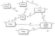
- FIG. 1a block diagram illustrating components in an RTLS, including tags, bridges, beacons, and a location engine.
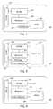
- FIG. 2is a block diagram illustrating components used in the tag
- FIG. 3is a block diagram illustrating components used in the bridge
- FIG. 4is a block diagram illustrating components used in the beacon with an included motion sensor.
- FIG. 5is a flow chart diagram for one embodiment of the invention, illustrating the steps using transmitting tags, bridges, beacons and location engine server to estimate tag location.
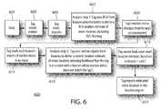
- FIG. 6is a flow chart diagram for an alternate embodiment of the invention, illustrating the steps using listening tags, bridges, beacons and location engine server to estimate tag location
- the embodimentsreside primarily in combinations of method steps and apparatus components related to an RTLS having stationary beacons that advertise, active tags that transmit advertisements, and bridges that pass beacon and tag information to a location algorithm in a central server. Accordingly, the apparatus components and method steps have been represented where appropriate by conventional symbols in the drawings, showing only those specific details that are pertinent to understanding the embodiments of the present invention so as not to obscure the disclosure with details that will be readily apparent to those of ordinary skill in the art having the benefit of the description herein.
- embodiments of the invention described hereinmay be comprised of one or more conventional processors and unique stored program instructions that control the one or more processors to implement, in conjunction with certain non-processor circuits, some, most, or all of the functions of RTLS having tags, bridges, and beacons.
- the non-processor circuitsmay include, but are not limited to, a radio receiver, a radio transmitter, signal drivers, clock circuits, power source circuits, and user input devices.
- these functionsmay be interpreted as steps of a method to perform energy-harvesting tags, bridges with mode-instruction, and tags, bridges and beacons that self-report location changes.
- FIG. 1a block diagram illustrating components used in the RTLS in accordance with various embodiments of the invention.
- the system 100includes one or more fixed (in-room) beacon transmitters 101 that operate using a signal transmission on one to three channels which contains a report of motion-status of moving objects in the beacon's room, as determined by a motion sensor in the beacon, a transmission that is received by a fixed infrastructure of bridges 104 and relayed to a central location server 105 , constructing a database of in-room beacons and the reported motion status patterns of their rooms.
- in-room beacon transmitters 101that operate using a signal transmission on one to three channels which contains a report of motion-status of moving objects in the beacon's room, as determined by a motion sensor in the beacon, a transmission that is received by a fixed infrastructure of bridges 104 and relayed to a central location server 105 , constructing a database of in-room beacons and the reported motion status patterns of their rooms.
- the motion status reported in the beacon's advertisementis at least one bit that toggles to represent “I see motion (in my room)” or “I see no motion (in my room)” and may also be several bits to include a description of how much motion is seen, and indicators of recent history of motion-state transitions.
- the history of motion statusmay indicate that there was no motion 1 minute ago, but there is motion now.
- One or more tags 103transmit a radio signal containing the tag's motion status to one or more bridges in a fixed infrastructure 104 .
- the motion statusis either a bit that says it is moving (or not), or numerical readings from its onboard accelerometer, or an increased transmission rate that implies that the tag is in motion.
- the bridgeretransmits the received signal strength of the tag's message, and the tag's motion status, via Wi-Fi to a central location server 105 .
- the central location servermay employ trilateration algorithms on the signal strength reports it receives from multiple bridges to form one estimate of the location of the tag.
- the central location server 105also processes the content of the tag's motion-status message, comparing it to the coincident motion status reported by the fixed beacons 101 .
- the location server 105may also analyze patterns of beacon-reported motion status over time, determining which patterns appear to be people walking along walking paths.
- the location server 105may also analyze signal-strength-based tag-location estimates over time, determining which patterns appear to be tags that are traveling along walking paths with those people. All of this information, including signal strengths of tag transmissions heard at the bridges, coincident motion reports from the tags and fixed beacons, and coincidence of human movement and tag movement, is factored into the location algorithm at the central location server.
- the central location serverproduces a “location estimate” for the tag, which is defined as an estimate of which room in the building the tag is located in.
- the system in FIG. 1includes a novel feature not taught in the prior art namely; a system of beacons, tags, bridges and a location engine, which enables the location engine to combine two location estimates: one multi-laterated location estimate based on radio signals, and a second location estimate based on motion status of tags and motion reports of in-room beacons; to produce a combined location estimate, used to store a updated, estimated location of the room-location of the tag.
- FIG. 2is a block diagram illustrating system components used in the tag.
- the tag 200includes a transceiver 201 that works to transmit and receive radio frequency (RF) signals.
- the transceiver 201is connected to a microprocessor 203 for controlling the operation of the transceiver.
- the transceiveris also connected to an antenna 205 for providing communication to other devices.
- the tagfurther includes an accelerometer 207 connected to microprocessor 203 for detecting motion of the tag and a battery 209 for powering electronic components in the device.
- FIG. 3is a block diagram illustrating components used in the bridge as seen in FIG. 1 .
- the bridge 300includes one or more transceivers 301 that connect to a microprocessor 303 for controlling operation of the transceiver(s) 301 .
- a Wi-Fi processor 305also connects to the processor 303 for transmitting and receiving Wi-Fi signals.
- An AC power supply 307is connected to the transceiver 301 , microprocessor 303 and the Wi-Fi processor 305 for powering these devices.
- the AC power supply 307may include components for retention of some energy even after being unplugged for some time period.
- An antenna 309is connected to both the transceiver 301 and the Wi-Fi processor 305 for transmitting and receiving Wi-Fi RF signals to these devices at the appropriate frequency.
- the bridge 300includes an optional in-room motion sensor 311 , such as a Passive-Infrared sensor, which detects human motion in the room where the bridge is located, by tracking changes in the infrared radiation in the room.
- the bridge 300 having a motion sensor 311can determine the timing of any moving objects in its same room, which helps populate a system database of which rooms have moving objects at what time. This data can then be transmitted and/or stored in a database for correlation to motion status of one or more tags.
- FIG. 4is a block diagram illustrating components used in the beacon.
- the beacon 400includes components for transmitting RF advertisements and includes one or more transceivers 401 that connect to a microprocessor 403 for controlling the transceiver(s).
- a battery 405connects to the transceiver(s) 401 and the microprocessor 403 for powering these devices.
- the beacon 400typically is placed on the ceiling of a room.
- the beacon 400includes one or more antennas 407 for providing gain, possibly to mitigate multipath fading between the tag and the beacon antenna.
- the beacon 400includes an in-room motion sensor 409 , connected to both the microprocessor 403 and battery 405 .
- the motion sensormay be a Passive-Infrared sensor, which detects human motion in the room where the bridge is located, by tracking changes in the infrared radiation in the room.
- the beacon 400 having a motion sensor 409can determine the presence and timing of any moving objects in its same room, which helps populate a system database of which rooms have moving objects at what time. This data will then be transmitted to the bridge 104 and/or stored in a database for correlation to motion status of one or more tags.
- FIG. 5is a block diagram illustrating a method in using the tags, bridges and location engine server to estimate tag location.
- the method 500starts 501 where a tag, using its accelerometer, senses motion 503 .
- the tagthen sends an advertisement 505 , reporting its motion status as sensed by its accelerometer.
- Multiple bridgesmeasure the characteristics of the tag advertisements they receive; characteristics that include at least the received signal strength (RSSI).
- RSSIreceived signal strength
- Multiple bridgesforward the tag advertisement's reported motion status and RSSI to a location engine 507 , as is common in the industry.
- the location engineinitially estimates position of the tag by using the RSSI measurement 509 .
- a second estimatecan be calculated that uses matching of coincident motion statuses: for example, matching the timing of the detection of motion by a bridge or beacon in a particular room 513 , (the history of which is stored in a location-engine-based room-motion-history database), to the coincident timing of motion-status changes of the tag. For example, if a tag's history of motion status shows that it was moving but stopped at time “x”, and only room “y” in a candidate list of rooms showed a coincident history of motion at time “x”, the second estimate may locate the tag in that room “y” because of a match in coincident motion.
- a third location estimateis made by the location engine based on both the RSSI measurement (the first location estimate) and the motion detection by the bridges, beacons and tags (the second location estimate).
- FIG. 6is a block diagram illustrating an alternate embodiment of the location process, using processing in a “listening” tag.
- the methods 600as shown in FIG. 6 including starting the process 601 where a tag senses motion 603 .
- the tagwill listen on the channel where the beacons are transmitting and determine which beacon signals it receives 605 .
- the tagwill perform a filtering process and an analysis of the signal strength of beacons it hears, forming a first location estimate of its own room-location based on signal strengths. This analysis determines a list of neighboring beacons 607 .
- the tag's motion statuschanges, as determined by the tag's onboard accelerometer 609 , the tag reads the motion status reported by each of the neighboring beacons 611 .
- the tagperforms a second analysis step 613 , using motion reports from the neighboring beacons to derive a second estimate of room-location, preferring beacons whose motion status matches its own motion status. For example, a tag that knows it is moving (because of a reading from its own accelerometer) may hear two beacons. If beacon A reports “I see motion in my room” status, and beacon B reports “I see no motion in my room” status, then the tag will prefer to estimate that it is in the same room with beacon A, because of coincident motion. (The moving tag is unlikely to be in the same room with beacon B because beacon B does not see any moving tags.) The tag considers both radio signal strength and matches of motion status in an estimate of the tag's room-location 615 . The tag then transmits an update message 617 to a location engine. The location engine will then record the tag's assessment of its room-location.
- An advance in the current inventionis the use of motion-status and in-room motion history, both in the moving tag and in the ceiling-mounted beacons.
- Radio frequency signalstravel through walls.
- the location enginethat relies solely on radio frequency signals to determine location has no information to determine which side of a wall that a tag is located.
- determining which side of a wall an asset is on, and thereby determining which room an asset is inis of the utmost importance. Therefore, an RTLS system may wish to estimate and report which room an asset is in, taking care to understand the wall-boundaries.
- hospital assetsare often stored in two adjacent rooms where the two rooms that share a common wall.
- One roomholds clean patient-care equipment, and the second room holds soiled equipment.
- the equipmentis placed on shelves that are against the shared wall. Therefore, from a physical-space perspective, clean assets are six inches on one side of a wall and soiled assets are six inches on the opposite side of the wall.
- a nurse using an RTLS system to find clean equipmentneeds to know which side of the wall an asset resides.
- Current, RTLS systems that use solely radio signals to locate the assetswill struggle to provide the correct room-location estimate, in view of their relative close proximity.
- radio signals sent by a tag to the multiple bridgeswill suffer from a variety of polarity fades (mismatches between the polarity of the transmitting antenna on the tag and the receive antenna on the bridge).
- These polarity fadeswork to dispel the general assumption that the RSSI of the advertisement from the tag to the bridge is directly correlated to the distance between the tag and the bridge. Therefore, this adds error to the location estimate, mis-estimating which room a clean or soiled asset is placed in.
- some of the tagswill be blocked (by metal objects or other assets) from a clear line of sight to the one or more bridges, further breaking the correlation of signal strength to distance.
- tagswill have their radio energy absorbed by human bodies or bags of water, further breaking the relationship of signal strength to distance.
- the tagmay be placed in a location where it happens to suffer from a persistent multipath fade relative to a specific bridge, so that bridge will mis-estimate its distance to the tag.
- all of these radio fading effectsare time-varying, as people and metal objects move through the hospital's rooms, so using radio signal strength alone to estimate the location of an asset tag will make a stationary asset appear to move from time to time.
- the present inventionuses motion sensors to help determine which room a tag is located.
- Motion sensorshave a relative advantage in that they perceive the motion inside a room, but they are shielded (by the wall) from sensing any motion in the adjacent room.
- the beacon inside the clean-storage roomhas a motion sensor, e.g. a passive infrared (PIR) sensor.
- PIRpassive infrared
- the beacon inside the soiled-storage roomhas its own motion sensor.
- Each motion sensorcan detect motion of assets or people inside its room, and detect lack of motion, and perhaps detect the difference between limited motion (like a patient sitting in a chair) and walking motion. Neither motion sensor can sense any motion on the opposite side of the shared wall.
- each beacon in each roomsends a regular advertisement.
- the beaconsenses no motion in its room, it includes that no-motion status data in its advertisement.
- the beaconsenses motion in its room, it includes that motion-sensor reading in its advertisement.
- the beaconmay also declare its motion-sense-status as more like a patient sitting in a bed, or more like a human walking through the room, for further accuracy of tag-location fixes.
- bridgesare placed throughout the floor plan within receive range of each beacon. Therefore, the bridge can hear and relay to the location engine, advertisements from the beacon that inform the location engine of the motion status in each beacon's room.
- the location enginebuilds up a history of the motion patterns in each room of the hospital, which may be stored in a database.
- the location enginerecords timestamps of motion-status changes in each room, such as when a room transitions from “no motion” to “walking motion”—which it may interpret as a human walking into an otherwise quiet room. Since motion-status changes in one room are likely to be non-coincident with motion-status changes in an adjacent room, each room will have a unique “motion fingerprint” for its last few minutes of observed time.
- each tagcontains an accelerometer.
- the tagalways knows when it is moving, when it is not moving, and when it transitions from movement to stopped, with some sense of the pace of movement.
- Bridges or gatewayscan determine when a tag starts or stops moving, either explicitly because the tag includes it in a transmitted message, or implicitly because a tag transmits at a different rate when it is moving.
- the location enginemay execute three separate methods or algorithms.
- the firstis a radio signal-strength (RSSI) algorithm.
- RSSIradio signal-strength
- the algorithmcan, however, determine a set of rooms that are possible/candidate locations.
- a second location algorithmis employed.
- the location engineuses its knowledge of the timestamps of motion changes in all rooms near where the first location algorithm has estimated the tag location.
- the second algorithmcompares the tag's report of motion changes e.g. “I was moving at walking speed, and I stopped at this time” to the reported motion-status changes of three or four rooms in the vicinity of the tag.
- Room Amay have had zero motion throughout that timeframe
- Room Bmay have had limited motion throughout the timeframe
- Room Csaw a coincident transition from “walking motion” to “no motion”. Therefore, this second algorithm estimates that a person brought the asset into room C, put it on a shelf, and left the room.
- the third location enginethen blends the estimate from the first and second location algorithms with some algorithmic information on room-to-room transitions that are most likely (such as “hallway” to “room”), to provide a final estimate of the room-location of each asset.
- the system and methods according to the present inventioncan quickly locate the asset because the RTLS architecture places a beacon at the doorway or ceiling of each room. If the RTLS used only radio signal strength to determine location of the asset, the signal between a beacon and the asset tag in the same room may be blocked by metal objects, reduced by polarization effects, or faded by multipath interference, to the point where the asset tag hears a beacon in an adjacent room more strongly than it hears the beacon in its own room.
- the RTLS using only radio signal strengthwill provide inaccurate locations or mis-estimates of the asset.
- RSSI measurementsif there were numerous assets lined up on the shelves on both sides of the wall, it is likely that many of the assets would be mis-estimated and recorded in the incorrect room.
- the location enginemay analyze multiple location reports over time, and multiple samples of room-motion status over time, to sharpen the room-location fix of a tag.
- tagged assetsmove at walking speed between rooms ONLY when accompanied by a person.
- prior art systemscan estimate the approximate route of the tagged asset by analyzing a series of approximated location fixes.
- the radio-multi-lateration systemcan determine, perhaps, that a tagged asset was carried on a route down a hallway and entered one of the rooms “on the left”, but it cannot be certain which room was entered.
- Room-based motion-detecting systems in current deployment todaycan track human motion on a walking route, from one room, via adjacent hallways and rooms to a destination room, by tracking a set of room-based and hallway-based motion sensors that report motion in a directional sequence.
- a networked set of motion sensorscan conclude that a human is walking a route down the hallway and (with room-level accuracy) entered a specific room. (As an example, the conclusion may be that a human has walked down the hall into room 603 ).
- a method and systemthat can correlate the estimated route of a tag, with the room-level-accurate walking route of a walking human person. Through that correlation, the system is estimating which person is carrying or escorting that tag as it moves. (For example, if the system discerns that a tag is moving with a specific person, and the system knows the specific person has entered room 603 , the system can conclude with high confidence that the tag has entered room 603 ). While traditional radio-based location engines can only weakly estimate which room a tag has entered, the present system and methods can use the likely association of a tag to a person, accompanied by a certainty about which room that the person has entered, to strongly estimate the room-location of the tag.
- the motion sensor 409 attached to a beacon 400may be able to discriminate multiple statuses of motion, for example it can distinguish between no motion, the motion of a patient sitting in a bed or chair, and the motion of a human walking in a room.
- the tag's accelerometeralso can discriminate between no motion, partial-body motion, and walking motion. These multiple statuses of motion establish data points to help tags determine whether location changes have occurred for personnel-tracking. The motion of a patient sitting in a bed or chair will not fool the tag into giving erroneous data that it has moved, but instead the tag will be correlating room-changes to the walking motion i.e. the perceived coincidentally in the tag's accelerometer and the beacon's motion sensor.
- the location engine in the current inventionuses at least three algorithmic method and/or processes in series to estimate the location of a tag. These processes include:
- Various embodiments of the present inventionare further directed to a real-time location system (RTLS) having simple transmitting tags, bridges, and beacons.
- RTLSreal-time location system
- beaconsbroadcast BLE advertisements containing motion-status information about recent history of perceived motion in a room as determined from a motion sensor in the beacon.
- Bridgesforward the beacon advertisements they hear to a location engine, which records timestamps of motion events seen by each beacon in each room.
- Simple transmitting tagsreport their own motion status based on a tag-based accelerometer.
- a series of location-engine stepsestimates the room-location of the tags based on a specific combination of RSSI analysis, and a comparison of tag-motion history to the perceived and recorded motion-status in a room.
- the analysis of tag-motion history and motion-in-room statusproduces a better estimate of room-level location of the tag than can be estimated by simple proximity or multi-lateration using radio signal strength alone.
- An alternate embodiment of the present inventionis directed to a real-time location system (RTLS) having listening tags, bridges, and beacons.
- Beaconsbroadcast advertisements containing motion-status information about recent history of perceived motion in a room as determined from a motion sensor in the beacon.
- Listening tagshear these broadcasts, and estimate their own room-location: first by analyzing which beacons are strongest, and then by analyzing which beacons report seeing motion at the same time that the tag is in motion. (Tags know their own motion status based on a tag-based accelerometer.)
- the analysis of tag-motion history and motion-in-room statusproduces a better estimate of room-level location of the tag than can be estimated by simple proximity or multi-lateration using radio signal strength alone.
Landscapes
- Engineering & Computer Science (AREA)
- Computer Networks & Wireless Communication (AREA)
- Signal Processing (AREA)
- Physics & Mathematics (AREA)
- General Physics & Mathematics (AREA)
- Radar, Positioning & Navigation (AREA)
- Remote Sensing (AREA)
- Automation & Control Theory (AREA)
- Computer Security & Cryptography (AREA)
- Electromagnetism (AREA)
- Position Fixing By Use Of Radio Waves (AREA)
- Radar Systems Or Details Thereof (AREA)
Abstract
Description
- 1) Measurements of the signal strengths of tag advertisements, received by the bridges, employing proximity or trilateration analysis and motion-history analysis, to estimate room location from messages transmitted by the tag, as is common in the industry.
- 2) Each beacon will advertise the motion status as perceived by its motion sensor, and each bridge report the motion-status of each beacon it hears, allowing the location engine to develop history of motion perceived in each room. Optionally, the bridge may have a motion sensor, and the bridge may add information on the motion status it sees in its room. The location engine can combine history of motion patterns in each room with the patterns of accelerometer-determined motion changes from individual tags, to estimate the room location of a tag.
- 3) Finally, the tag or location engine blends its room-location estimates from the two algorithms above to finalize its location estimate for the tag.
Claims (3)
Priority Applications (3)
| Application Number | Priority Date | Filing Date | Title |
|---|---|---|---|
| US16/214,890US10390182B2 (en) | 2016-05-31 | 2018-12-10 | Real-time location system (RTLS) having tags, beacons and bridges, that uses a combination of motion detection and RSSI measurements to determine room-location of the tags |
| PCT/US2019/037667WO2019246049A1 (en) | 2018-06-18 | 2019-06-18 | A real-time location system (rtls) that uses a combination of event sensors and rssi measurements to determine room-and-bay-location of tags |
| EP19822878.5AEP3807853A1 (en) | 2018-06-18 | 2019-06-18 | A real-time location system (rtls) that uses a combination of event sensors and rssi measurements to determine room-and-bay-location of tags |
Applications Claiming Priority (5)
| Application Number | Priority Date | Filing Date | Title |
|---|---|---|---|
| US201662343242P | 2016-05-31 | 2016-05-31 | |
| US201662430559P | 2016-12-06 | 2016-12-06 | |
| US15/610,072US10028105B1 (en) | 2016-05-31 | 2017-05-31 | Bluetooth low energy (BLE) real-time location system (RTLS) having tags that harvest energy, bridges that instruct tags to toggle beacon modes on and off, beacons and bridges that self-report location changes, and optional use of a single beacon channel |
| US16/010,732US10231078B1 (en) | 2016-05-31 | 2018-06-18 | Bluetooth low energy (BLE) real-time location system (RTLS) having simple transmitting tags, beacons and bridges, that use a combination of motion detection and RSSI measurements to determine room-location of the tags |
| US16/214,890US10390182B2 (en) | 2016-05-31 | 2018-12-10 | Real-time location system (RTLS) having tags, beacons and bridges, that uses a combination of motion detection and RSSI measurements to determine room-location of the tags |
Related Parent Applications (1)
| Application Number | Title | Priority Date | Filing Date |
|---|---|---|---|
| US16/010,732Continuation-In-PartUS10231078B1 (en) | 2016-05-31 | 2018-06-18 | Bluetooth low energy (BLE) real-time location system (RTLS) having simple transmitting tags, beacons and bridges, that use a combination of motion detection and RSSI measurements to determine room-location of the tags |
Publications (2)
| Publication Number | Publication Date |
|---|---|
| US20190124475A1 US20190124475A1 (en) | 2019-04-25 |
| US10390182B2true US10390182B2 (en) | 2019-08-20 |
Family
ID=66171330
Family Applications (1)
| Application Number | Title | Priority Date | Filing Date |
|---|---|---|---|
| US16/214,890ActiveUS10390182B2 (en) | 2016-05-31 | 2018-12-10 | Real-time location system (RTLS) having tags, beacons and bridges, that uses a combination of motion detection and RSSI measurements to determine room-location of the tags |
Country Status (1)
| Country | Link |
|---|---|
| US (1) | US10390182B2 (en) |
Cited By (4)
| Publication number | Priority date | Publication date | Assignee | Title |
|---|---|---|---|---|
| US11877058B1 (en) | 2022-08-25 | 2024-01-16 | Benjamin Slotznick | Computer program product and automated method for auto-focusing a camera on a person in a venue who is wearing, or carrying, or holding, or speaking into a microphone at the venue |
| US11889187B1 (en) | 2022-08-25 | 2024-01-30 | Benjamin Slotznick | Computer program product and method for auto-focusing one or more lighting fixtures on selected persons in a venue who are performers of a performance occurring at the venue |
| US11889188B1 (en)* | 2022-08-25 | 2024-01-30 | Benjamin Slotznick | Computer program product and method for auto-focusing one or more cameras on selected persons in a venue who are performers of a performance occurring at the venue |
| US11902659B1 (en)* | 2022-08-25 | 2024-02-13 | Benjamin Slotznick | Computer program product and method for auto-focusing a lighting fixture on a person in a venue who is wearing, or carrying, or holding, or speaking into a microphone at the venue |
Families Citing this family (16)
| Publication number | Priority date | Publication date | Assignee | Title |
|---|---|---|---|---|
| CN111601233B (en)* | 2019-02-21 | 2022-06-28 | 昆山纬绩资通有限公司 | Monitoring method and system for positioning device |
| US10970988B2 (en)* | 2019-03-29 | 2021-04-06 | Canon Kabushiki Kaisha | Information processing apparatus, information processing system, method, and program |
| JP6667819B1 (en)* | 2019-07-22 | 2020-03-18 | 株式会社Social Area Networks | Positioning method, its system and positioning communication device |
| EP4014522A4 (en) | 2019-08-13 | 2023-08-02 | Milwaukee Electric Tool Corporation | Tool tracking system |
| US11363419B2 (en)* | 2019-12-10 | 2022-06-14 | Hill-Rom Services, Inc. | Intelligent location estimation for assets in clinical environments |
| US20210357907A1 (en)* | 2020-05-12 | 2021-11-18 | Deeyook Location Technologies Ltd. | System, apparatus, and/or method for providing wireless applications based on locationing solutions |
| MX2021005929A (en) | 2020-05-20 | 2021-11-22 | 3Si Security Systems Inc | Security tracking device with zone-based alert suppression. |
| US12349026B2 (en)* | 2020-07-27 | 2025-07-01 | C3-Wireless, Llc | Systems for real time location services (RTLS) |
| TWI741821B (en)* | 2020-10-07 | 2021-10-01 | 廣達電腦股份有限公司 | Electronic device with gravity sensor assisted positioning |
| US11742964B2 (en)* | 2020-12-30 | 2023-08-29 | United Parcel Services Of America, Inc. | Location sensing technology for detecting asset location |
| US11595835B2 (en)* | 2021-04-20 | 2023-02-28 | Cisco Technology, Inc. | Service cognizant radio role assignments |
| US12375877B2 (en) | 2021-04-30 | 2025-07-29 | Emanate Wireless, Inc. | Wireless room occupancy monitor |
| US20220381875A1 (en)* | 2021-06-01 | 2022-12-01 | Midmark RTLS Solutions Inc. | Real-time locating system |
| IT202100021221A1 (en)* | 2021-08-05 | 2023-02-05 | Forwardinnovation S R L | Real-time location system |
| WO2023249658A1 (en)* | 2022-06-23 | 2023-12-28 | Hid Global Bluvision, Inc. | Thermal imaging for room-level real-time location services |
| US12204980B2 (en) | 2022-12-28 | 2025-01-21 | United Parcel Service Of America, Inc. | Intelligent logistics vehicle for detecting asset location |
Citations (27)
| Publication number | Priority date | Publication date | Assignee | Title |
|---|---|---|---|---|
| US20070046434A1 (en) | 2005-08-31 | 2007-03-01 | Skyetek, Inc. | Decoupled RFID reader and interrogator |
| US20070247366A1 (en)* | 2003-10-22 | 2007-10-25 | Smith Derek M | Wireless postion location and tracking system |
| US20110072132A1 (en) | 2009-09-21 | 2011-03-24 | Checkpoint Systems, Inc. | Retail Product Tracking System, Method, and Apparatus |
| US20110080267A1 (en) | 2009-10-02 | 2011-04-07 | Checkpoint Systems, Inc. | Calibration of Beamforming Nodes in a Configurable Monitoring Device System |
| US20130141233A1 (en) | 2011-02-23 | 2013-06-06 | Embedrf Llc | Position tracking and mobility assessment system |
| US20130201003A1 (en) | 2010-04-26 | 2013-08-08 | Sithamparanathan Sabesan | Rfid tag location systems |
| US20130324147A1 (en) | 2012-05-30 | 2013-12-05 | Comcast Cable Communications, Llc | Access Node Locations in a Network |
| US20140351498A1 (en) | 2009-05-12 | 2014-11-27 | HGST Netherlands B.V. | Systems and methods for read caching in flash storage |
| US20150002274A1 (en) | 2013-06-26 | 2015-01-01 | Trackblue, Llc | Asset Tag Apparatus and Related Methods |
| US20150063427A1 (en) | 2009-08-25 | 2015-03-05 | The Aerospace Corporation | Phase-Optimized Constant Envelope Transmission (POCET) Method, Apparatus And System |
| US20150063472A1 (en) | 2013-08-28 | 2015-03-05 | Geoffrey W. Chatterton | Wireless technology bridging system |
| US20150286852A1 (en)* | 2014-04-06 | 2015-10-08 | Trackblue, Llc | Wireless Medication Compliance Sensing Device, System, and Related Methods |
| US20160029160A1 (en)* | 2014-07-25 | 2016-01-28 | Charles Theurer | Wireless bridge hardware system for active rfid identification and location tracking |
| US20160029176A1 (en)* | 2014-07-23 | 2016-01-28 | Apple Inc. | Providing personalized content based on historical interaction with a mobile device |
| US20160260301A1 (en) | 2015-03-02 | 2016-09-08 | Enovate Medical, Llc | Asset management using an asset tag device |
| US20160267144A1 (en)* | 2015-03-12 | 2016-09-15 | WeLink, Inc. | Collecting and generating geo-tagged social media data through a network router interface |
| US20160295358A1 (en) | 2013-09-27 | 2016-10-06 | Blue Sync Limited | Communication method and system |
| US20160295376A1 (en) | 2015-04-06 | 2016-10-06 | Awarepoint Corporation | Bluetooth low energy location system and method |
| US20160299213A1 (en)* | 2015-04-10 | 2016-10-13 | Enovate Medical, Llc | Asset tags |
| US20170127128A1 (en)* | 2015-11-02 | 2017-05-04 | Stephen Vollentine Seger | Social Post Roll Up and Management System and Method of Use |
| US20170142639A1 (en) | 2015-11-18 | 2017-05-18 | At&T Mobility Ii Llc | Locating physical assets via near field communication nodes |
| US20170142549A1 (en) | 2015-11-12 | 2017-05-18 | Trackr, Inc. | System and method for tracking items within a defined area |
| US20170195834A1 (en)* | 2016-01-05 | 2017-07-06 | Samsung Electronics Co., Ltd. | Method and apparatus for estimating location in a terminal |
| US20170313426A1 (en) | 2014-11-14 | 2017-11-02 | Bombardier Inc. | In-vehicle position detection and configuration of vehicle components |
| US9810767B1 (en) | 2015-06-16 | 2017-11-07 | Michael Hamilton | Location estimation system |
| US9877298B1 (en) | 2016-03-22 | 2018-01-23 | Massachusetts Mutual Life Insurance Company | Beacon-based location introduction system |
| US20180273344A1 (en)* | 2015-09-23 | 2018-09-27 | Inventio Ag | Wire bridge monitoring system |
- 2018
- 2018-12-10USUS16/214,890patent/US10390182B2/enactiveActive
Patent Citations (27)
| Publication number | Priority date | Publication date | Assignee | Title |
|---|---|---|---|---|
| US20070247366A1 (en)* | 2003-10-22 | 2007-10-25 | Smith Derek M | Wireless postion location and tracking system |
| US20070046434A1 (en) | 2005-08-31 | 2007-03-01 | Skyetek, Inc. | Decoupled RFID reader and interrogator |
| US20140351498A1 (en) | 2009-05-12 | 2014-11-27 | HGST Netherlands B.V. | Systems and methods for read caching in flash storage |
| US20150063427A1 (en) | 2009-08-25 | 2015-03-05 | The Aerospace Corporation | Phase-Optimized Constant Envelope Transmission (POCET) Method, Apparatus And System |
| US20110072132A1 (en) | 2009-09-21 | 2011-03-24 | Checkpoint Systems, Inc. | Retail Product Tracking System, Method, and Apparatus |
| US20110080267A1 (en) | 2009-10-02 | 2011-04-07 | Checkpoint Systems, Inc. | Calibration of Beamforming Nodes in a Configurable Monitoring Device System |
| US20130201003A1 (en) | 2010-04-26 | 2013-08-08 | Sithamparanathan Sabesan | Rfid tag location systems |
| US20130141233A1 (en) | 2011-02-23 | 2013-06-06 | Embedrf Llc | Position tracking and mobility assessment system |
| US20130324147A1 (en) | 2012-05-30 | 2013-12-05 | Comcast Cable Communications, Llc | Access Node Locations in a Network |
| US20150002274A1 (en) | 2013-06-26 | 2015-01-01 | Trackblue, Llc | Asset Tag Apparatus and Related Methods |
| US20150063472A1 (en) | 2013-08-28 | 2015-03-05 | Geoffrey W. Chatterton | Wireless technology bridging system |
| US20160295358A1 (en) | 2013-09-27 | 2016-10-06 | Blue Sync Limited | Communication method and system |
| US20150286852A1 (en)* | 2014-04-06 | 2015-10-08 | Trackblue, Llc | Wireless Medication Compliance Sensing Device, System, and Related Methods |
| US20160029176A1 (en)* | 2014-07-23 | 2016-01-28 | Apple Inc. | Providing personalized content based on historical interaction with a mobile device |
| US20160029160A1 (en)* | 2014-07-25 | 2016-01-28 | Charles Theurer | Wireless bridge hardware system for active rfid identification and location tracking |
| US20170313426A1 (en) | 2014-11-14 | 2017-11-02 | Bombardier Inc. | In-vehicle position detection and configuration of vehicle components |
| US20160260301A1 (en) | 2015-03-02 | 2016-09-08 | Enovate Medical, Llc | Asset management using an asset tag device |
| US20160267144A1 (en)* | 2015-03-12 | 2016-09-15 | WeLink, Inc. | Collecting and generating geo-tagged social media data through a network router interface |
| US20160295376A1 (en) | 2015-04-06 | 2016-10-06 | Awarepoint Corporation | Bluetooth low energy location system and method |
| US20160299213A1 (en)* | 2015-04-10 | 2016-10-13 | Enovate Medical, Llc | Asset tags |
| US9810767B1 (en) | 2015-06-16 | 2017-11-07 | Michael Hamilton | Location estimation system |
| US20180273344A1 (en)* | 2015-09-23 | 2018-09-27 | Inventio Ag | Wire bridge monitoring system |
| US20170127128A1 (en)* | 2015-11-02 | 2017-05-04 | Stephen Vollentine Seger | Social Post Roll Up and Management System and Method of Use |
| US20170142549A1 (en) | 2015-11-12 | 2017-05-18 | Trackr, Inc. | System and method for tracking items within a defined area |
| US20170142639A1 (en) | 2015-11-18 | 2017-05-18 | At&T Mobility Ii Llc | Locating physical assets via near field communication nodes |
| US20170195834A1 (en)* | 2016-01-05 | 2017-07-06 | Samsung Electronics Co., Ltd. | Method and apparatus for estimating location in a terminal |
| US9877298B1 (en) | 2016-03-22 | 2018-01-23 | Massachusetts Mutual Life Insurance Company | Beacon-based location introduction system |
Cited By (5)
| Publication number | Priority date | Publication date | Assignee | Title |
|---|---|---|---|---|
| US11877058B1 (en) | 2022-08-25 | 2024-01-16 | Benjamin Slotznick | Computer program product and automated method for auto-focusing a camera on a person in a venue who is wearing, or carrying, or holding, or speaking into a microphone at the venue |
| US11889187B1 (en) | 2022-08-25 | 2024-01-30 | Benjamin Slotznick | Computer program product and method for auto-focusing one or more lighting fixtures on selected persons in a venue who are performers of a performance occurring at the venue |
| US11889188B1 (en)* | 2022-08-25 | 2024-01-30 | Benjamin Slotznick | Computer program product and method for auto-focusing one or more cameras on selected persons in a venue who are performers of a performance occurring at the venue |
| US11902659B1 (en)* | 2022-08-25 | 2024-02-13 | Benjamin Slotznick | Computer program product and method for auto-focusing a lighting fixture on a person in a venue who is wearing, or carrying, or holding, or speaking into a microphone at the venue |
| US12267589B1 (en) | 2022-08-25 | 2025-04-01 | Benjamin Slotznick | Computer program product and automated method for auto-focusing a camera and/or a lighting fixture on one of a plurality of microphones in a venue that is being worn, carried, held, or spoken into by a person at the venue |
Also Published As
| Publication number | Publication date |
|---|---|
| US20190124475A1 (en) | 2019-04-25 |
Similar Documents
| Publication | Publication Date | Title |
|---|---|---|
| US10390182B2 (en) | Real-time location system (RTLS) having tags, beacons and bridges, that uses a combination of motion detection and RSSI measurements to determine room-location of the tags | |
| US10231078B1 (en) | Bluetooth low energy (BLE) real-time location system (RTLS) having simple transmitting tags, beacons and bridges, that use a combination of motion detection and RSSI measurements to determine room-location of the tags | |
| US10251020B1 (en) | Bluetooth low energy (BLE) real-time location system (RTLS) having tags, beacons and bridges, that use a combination of motion detection and RSSI measurements to determine room-location of the tags | |
| US7545326B2 (en) | Wireless tracking system and method with multipath error mitigation | |
| US8457656B2 (en) | Wireless tracking system and method utilizing multiple location algorithms | |
| US12372645B2 (en) | Transmitting device for use in location determination systems | |
| US7504928B2 (en) | Wireless tracking system and method utilizing tags with variable power level transmissions | |
| KR101349980B1 (en) | Real time location system and method for making a location information based on finger printing | |
| US10412700B2 (en) | Portable-device-locating system that uses room-level motion sensors and RSSI measurements to determine precise room-location | |
| US20060013070A1 (en) | Ultrasonic tracking and locating system | |
| Zhu et al. | Survey of indoor positioning technologies and systems | |
| JP2011529217A (en) | Method and system for determining the position of a subject | |
| US20210306803A1 (en) | Room-level event sensor-initiated real-time location system (rtls) | |
| US9086469B2 (en) | Low frequency magnetic induction positioning system and method | |
| WO2023281506A2 (en) | System and method for determining object location | |
| Liu et al. | A novel indoor localization system based on passive RFID technology | |
| WO2019246049A1 (en) | A real-time location system (rtls) that uses a combination of event sensors and rssi measurements to determine room-and-bay-location of tags | |
| Bragin et al. | Comparison of technologies of local patient positioning | |
| EP2594953B1 (en) | Height calibration process | |
| JP4498882B2 (en) | POSITIONING DEVICE AND POSITIONING METHOD | |
| JP2011203129A (en) | Position estimation system and method | |
| JP2017207295A (en) | Location detection system and location detection device | |
| JP2025014989A (en) | Information processing system, information processing device and information processing method | |
| Abd Rashid | RSSI Fingerprinting Approach for Location-Based Services |
Legal Events
| Date | Code | Title | Description |
|---|---|---|---|
| FEPP | Fee payment procedure | Free format text:ENTITY STATUS SET TO UNDISCOUNTED (ORIGINAL EVENT CODE: BIG.); ENTITY STATUS OF PATENT OWNER: LARGE ENTITY Free format text:ENTITY STATUS SET TO UNDISCOUNTED (ORIGINAL EVENT CODE: BIG.); ENTITY STATUS OF PATENT OWNER: SMALL ENTITY | |
| FEPP | Fee payment procedure | Free format text:ENTITY STATUS SET TO SMALL (ORIGINAL EVENT CODE: SMAL); ENTITY STATUS OF PATENT OWNER: LARGE ENTITY Free format text:ENTITY STATUS SET TO SMALL (ORIGINAL EVENT CODE: SMAL); ENTITY STATUS OF PATENT OWNER: SMALL ENTITY | |
| AS | Assignment | Owner name:INFINITE LEAP, INC., NORTH DAKOTA Free format text:ASSIGNMENT OF ASSIGNORS INTEREST;ASSIGNOR:SWART, JOHN A.;REEL/FRAME:047966/0518 Effective date:20181130 | |
| AS | Assignment | Owner name:INFINITE LEAP HOLDINGS, LLC, NORTH DAKOTA Free format text:ASSIGNMENT OF ASSIGNORS INTEREST;ASSIGNOR:INFINITE LEAP, INC.;REEL/FRAME:048595/0031 Effective date:20190312 | |
| STPP | Information on status: patent application and granting procedure in general | Free format text:NON FINAL ACTION MAILED | |
| STPP | Information on status: patent application and granting procedure in general | Free format text:RESPONSE TO NON-FINAL OFFICE ACTION ENTERED AND FORWARDED TO EXAMINER | |
| STPP | Information on status: patent application and granting procedure in general | Free format text:PUBLICATIONS -- ISSUE FEE PAYMENT VERIFIED | |
| STCF | Information on status: patent grant | Free format text:PATENTED CASE | |
| AS | Assignment | Owner name:INFINITE LEAP HOLDINGS, LLC, NORTH DAKOTA Free format text:CORRECTIVE ASSIGNMENT TO CORRECT THE CONVEYING PARTY OF STATE INCORPORATION ON DOCUMENT PREVIOUSLY RECORDED AT REEL: 48595 FRAME: 031. ASSIGNOR(S) HEREBY CONFIRMS THE ASSIGNMENT;ASSIGNOR:INFINITE LEAP, INC.;REEL/FRAME:057639/0846 Effective date:20190312 | |
| AS | Assignment | Owner name:INFINITE LEAP, INC., NORTH DAKOTA Free format text:ASSIGNMENT OF ASSIGNORS INTEREST;ASSIGNOR:INFINITE LEAP HOLDINGS, LLC;REEL/FRAME:057457/0421 Effective date:20210910 | |
| FEPP | Fee payment procedure | Free format text:ENTITY STATUS SET TO UNDISCOUNTED (ORIGINAL EVENT CODE: BIG.); ENTITY STATUS OF PATENT OWNER: LARGE ENTITY | |
| MAFP | Maintenance fee payment | Free format text:PAYMENT OF MAINTENANCE FEE, 4TH YEAR, LARGE ENTITY (ORIGINAL EVENT CODE: M1551); ENTITY STATUS OF PATENT OWNER: LARGE ENTITY Year of fee payment:4 |