US10387221B2 - Multiple interacting systems at a site - Google Patents
Multiple interacting systems at a siteDownload PDFInfo
- Publication number
- US10387221B2 US10387221B2US15/910,936US201815910936AUS10387221B2US 10387221 B2US10387221 B2US 10387221B2US 201815910936 AUS201815910936 AUS 201815910936AUS 10387221 B2US10387221 B2US 10387221B2
- Authority
- US
- United States
- Prior art keywords
- window
- windows
- control system
- building
- systems
- Prior art date
- Legal status (The legal status is an assumption and is not a legal conclusion. Google has not performed a legal analysis and makes no representation as to the accuracy of the status listed.)
- Active
Links
Images


Classifications
- G—PHYSICS
- G06—COMPUTING OR CALCULATING; COUNTING
- G06F—ELECTRIC DIGITAL DATA PROCESSING
- G06F9/00—Arrangements for program control, e.g. control units
- G06F9/06—Arrangements for program control, e.g. control units using stored programs, i.e. using an internal store of processing equipment to receive or retain programs
- G06F9/44—Arrangements for executing specific programs
- G06F9/451—Execution arrangements for user interfaces
- G—PHYSICS
- G05—CONTROLLING; REGULATING
- G05B—CONTROL OR REGULATING SYSTEMS IN GENERAL; FUNCTIONAL ELEMENTS OF SUCH SYSTEMS; MONITORING OR TESTING ARRANGEMENTS FOR SUCH SYSTEMS OR ELEMENTS
- G05B15/00—Systems controlled by a computer
- G05B15/02—Systems controlled by a computer electric
- E—FIXED CONSTRUCTIONS
- E06—DOORS, WINDOWS, SHUTTERS, OR ROLLER BLINDS IN GENERAL; LADDERS
- E06B—FIXED OR MOVABLE CLOSURES FOR OPENINGS IN BUILDINGS, VEHICLES, FENCES OR LIKE ENCLOSURES IN GENERAL, e.g. DOORS, WINDOWS, BLINDS, GATES
- E06B9/00—Screening or protective devices for wall or similar openings, with or without operating or securing mechanisms; Closures of similar construction
- E06B9/24—Screens or other constructions affording protection against light, especially against sunshine; Similar screens for privacy or appearance; Slat blinds
- G—PHYSICS
- G02—OPTICS
- G02F—OPTICAL DEVICES OR ARRANGEMENTS FOR THE CONTROL OF LIGHT BY MODIFICATION OF THE OPTICAL PROPERTIES OF THE MEDIA OF THE ELEMENTS INVOLVED THEREIN; NON-LINEAR OPTICS; FREQUENCY-CHANGING OF LIGHT; OPTICAL LOGIC ELEMENTS; OPTICAL ANALOGUE/DIGITAL CONVERTERS
- G02F1/00—Devices or arrangements for the control of the intensity, colour, phase, polarisation or direction of light arriving from an independent light source, e.g. switching, gating or modulating; Non-linear optics
- G02F1/01—Devices or arrangements for the control of the intensity, colour, phase, polarisation or direction of light arriving from an independent light source, e.g. switching, gating or modulating; Non-linear optics for the control of the intensity, phase, polarisation or colour
- G02F1/15—Devices or arrangements for the control of the intensity, colour, phase, polarisation or direction of light arriving from an independent light source, e.g. switching, gating or modulating; Non-linear optics for the control of the intensity, phase, polarisation or colour based on an electrochromic effect
- G02F1/163—Operation of electrochromic cells, e.g. electrodeposition cells; Circuit arrangements therefor
- G—PHYSICS
- G06—COMPUTING OR CALCULATING; COUNTING
- G06F—ELECTRIC DIGITAL DATA PROCESSING
- G06F9/00—Arrangements for program control, e.g. control units
- G06F9/06—Arrangements for program control, e.g. control units using stored programs, i.e. using an internal store of processing equipment to receive or retain programs
- G06F9/46—Multiprogramming arrangements
- G06F9/54—Interprogram communication
- G—PHYSICS
- G06—COMPUTING OR CALCULATING; COUNTING
- G06Q—INFORMATION AND COMMUNICATION TECHNOLOGY [ICT] SPECIALLY ADAPTED FOR ADMINISTRATIVE, COMMERCIAL, FINANCIAL, MANAGERIAL OR SUPERVISORY PURPOSES; SYSTEMS OR METHODS SPECIALLY ADAPTED FOR ADMINISTRATIVE, COMMERCIAL, FINANCIAL, MANAGERIAL OR SUPERVISORY PURPOSES, NOT OTHERWISE PROVIDED FOR
- G06Q50/00—Information and communication technology [ICT] specially adapted for implementation of business processes of specific business sectors, e.g. utilities or tourism
- G06Q50/10—Services
- H—ELECTRICITY
- H04—ELECTRIC COMMUNICATION TECHNIQUE
- H04L—TRANSMISSION OF DIGITAL INFORMATION, e.g. TELEGRAPHIC COMMUNICATION
- H04L12/00—Data switching networks
- H04L12/28—Data switching networks characterised by path configuration, e.g. LAN [Local Area Networks] or WAN [Wide Area Networks]
- H04L12/2803—Home automation networks
- H04L12/2816—Controlling appliance services of a home automation network by calling their functionalities
- H04L12/282—Controlling appliance services of a home automation network by calling their functionalities based on user interaction within the home
- E—FIXED CONSTRUCTIONS
- E06—DOORS, WINDOWS, SHUTTERS, OR ROLLER BLINDS IN GENERAL; LADDERS
- E06B—FIXED OR MOVABLE CLOSURES FOR OPENINGS IN BUILDINGS, VEHICLES, FENCES OR LIKE ENCLOSURES IN GENERAL, e.g. DOORS, WINDOWS, BLINDS, GATES
- E06B9/00—Screening or protective devices for wall or similar openings, with or without operating or securing mechanisms; Closures of similar construction
- E06B9/24—Screens or other constructions affording protection against light, especially against sunshine; Similar screens for privacy or appearance; Slat blinds
- E06B2009/2464—Screens or other constructions affording protection against light, especially against sunshine; Similar screens for privacy or appearance; Slat blinds featuring transparency control by applying voltage, e.g. LCD, electrochromic panels
- G—PHYSICS
- G05—CONTROLLING; REGULATING
- G05B—CONTROL OR REGULATING SYSTEMS IN GENERAL; FUNCTIONAL ELEMENTS OF SUCH SYSTEMS; MONITORING OR TESTING ARRANGEMENTS FOR SUCH SYSTEMS OR ELEMENTS
- G05B2219/00—Program-control systems
- G05B2219/20—Pc systems
- G05B2219/26—Pc applications
- G05B2219/2614—HVAC, heating, ventillation, climate control
- G—PHYSICS
- G05—CONTROLLING; REGULATING
- G05B—CONTROL OR REGULATING SYSTEMS IN GENERAL; FUNCTIONAL ELEMENTS OF SUCH SYSTEMS; MONITORING OR TESTING ARRANGEMENTS FOR SUCH SYSTEMS OR ELEMENTS
- G05B2219/00—Program-control systems
- G05B2219/20—Pc systems
- G05B2219/26—Pc applications
- G05B2219/2628—Door, window
- G—PHYSICS
- G05—CONTROLLING; REGULATING
- G05B—CONTROL OR REGULATING SYSTEMS IN GENERAL; FUNCTIONAL ELEMENTS OF SUCH SYSTEMS; MONITORING OR TESTING ARRANGEMENTS FOR SUCH SYSTEMS OR ELEMENTS
- G05B2219/00—Program-control systems
- G05B2219/20—Pc systems
- G05B2219/26—Pc applications
- G05B2219/2642—Domotique, domestic, home control, automation, smart house
- G—PHYSICS
- G06—COMPUTING OR CALCULATING; COUNTING
- G06F—ELECTRIC DIGITAL DATA PROCESSING
- G06F17/00—Digital computing or data processing equipment or methods, specially adapted for specific functions
Definitions
- Electrochromic windowssometimes referred to as “smart windows,” have been deployed in limited installations. As such windows gain acceptance and are more widely deployed, they may require increasingly sophisticated control and monitoring systems, as there may be a various systems interacting with smart windows for the benefit of buildings and associated infrastructure. Improved techniques for managing interacting building systems are necessary.
- Certain aspects of the disclosurepertain to a plurality of interacting systems including a window control system and at least one other system which may be a lighting system, an HVAC systems, a security system, and/or a home appliance control system.
- the window control system and the at least one other systemare configured to communicate via an application programming interface (API).
- APIapplication programming interface
- the window control systemis configured to control the optical state of one or more optically switchable windows.
- the window control systemincludes a window controller configured to control transitions of at least one optically switchable window.
- the window control systemincludes a plurality of electrochromic windows in electrical communication with one or more window controllers configured to communicate over a network.
- the at least one other systemis the home appliance control system. In certain embodiments, the at least one other system is the HVAC system. In some implementations, the interacting systems additionally include a building management system configured to control the HVAC system. In such cases, the API may be configured to permit the window control system and the building management system to communicate. In certain embodiments, the at least one other system is the lighting system.
- the window control system and the at least one other systemare configured to provide data obtained or generated by the window control system to the at least one other system. In some implementations, the window control system and the at least one other system are configured such that the window control system controls one or more devices of the at least one other system.
- the window control system and the at least one other systemare configured such that the at least one other system controls one or more devices of the window control system.
- the at least one other systemis the HVAC system or the lighting system.
- the devices of the window control systeminclude a sensor and/or an optically switchable window.
- Another aspect of this disclosurepertains to methods of communicating among a plurality of interacting systems, which may be a window control system and at least one other system selected from the group consisting of a lighting system, an HVAC systems, a security system, and a home appliance control system.
- the methodis characterized by the following operations: (a) receiving a communication from the window control system or from the at least one other system and addressed to the other of the window control system and the at least one other system, wherein the communication has a format specified by an applications program interface (API) for communicating between the window control system and the at least one other system; (b) providing instructions and/or data contained in the communication to the addressed window control system or at least one other system; and (c) performing, at the addressed window control system or at least one other system, one or more operations using the instructions and/or data contained in the communication.
- APIapplications program interface
- the window control systemincludes a window controller configured to control transitions of at least one optically switchable window.
- the window control systemmay also include a plurality of electrochromic windows in electrical communication with one or more window controllers configured to communicate over a network.
- the at least one other systemis the home appliance control system. In certain embodiments, the at least one other system is the HVAC system. In some such embodiments, a building management system is configured to control the HVAC system, and the HVAC system receives the communication from the window control system via the API. In certain embodiments, the at least one other system is the lighting system.
- the at least one other systemreceives the communication from the window control system, and the communication includes data obtained or generated by the window control system. In some implementations, the at least one other system receives the communication from the window control system, and the communication includes instructions from the window control system for controlling one or more devices of the at least one other system.
- the window control systemreceives the communication from the at least one other system, and the communication includes instructions from the at least one other system for controlling one or more devices of the window control system.
- the devices controlled on the window control systeminclude a sensor and/or an optically switchable window.
- the at least one other systemis the HVAC system and/or the lighting system.
- FIG. 1Ais a block diagram of interacting systems, including a window system, interfacing with one another via APIs.
- FIG. 1Bis a block diagram of a smart window system for interfacing with external systems.
- FIG. 1Cdepicts a schematic diagram of an embodiment of a site with a building management system (BMS) for interacting with a window control network.
- BMSbuilding management system
- FIG. 1Ddepicts a block diagram of a building network.
- FIG. 1Eis a diagram of components of a window network for controlling functions of one or more tintable windows of a building.
- FIG. 2is a graph depicting voltage and current profiles associated with driving an electrochromic device from bleached to colored and from colored to bleached.
- FIG. 3is a graph depicting certain voltage and current profiles associated with driving an electrochromic device from bleached to colored.
- FIG. 4depicts a simplified block diagram of components of a window controller.
- FIG. 5depicts a schematic diagram of a room including a tintable window and at least one sensor.
- FIG. 6is a flowchart showing some steps of predictive control logic for a method of controlling one or more electrochromic windows in a building.
- This documentdescribes, inter alia, a platform for communicating among one or more otherwise independent systems involved in controlling functions of buildings or other sites having switchable optical devices deployed therein.
- independent systemsinclude a window control system and one or more other independent systems such as systems that control residential home products (e.g., NEST (Nest Labs of Palo Alto, Calif.), which controls thermostats, smoke alarms, etc.), HVAC systems, security systems, lighting control systems, and the like.
- NESTNational Labs of Palo Alto, Calif.
- HVAC systemse.g., thermostats, smoke alarms, etc.
- HVAC systemse.g., HVAC systems, security systems, lighting control systems, and the like.
- the systemscontrol and/or monitor multiple features and/or products, including switchable windows and other infrastructure of a site, which may be a commercial, residential, or public site.
- Networks and related infrastructurethat may be used with the disclosed embodiments are presented in FIGS. 1A-E , as well as in U.S. Provisional Patent Application No. 62
- a sitehas one or more controllers that control the switching of one or more deployed devices.
- the sitemay also have sensors such as light sensors, thermal sensors, and/or occupancy sensors that provide data used in making decisions about when and by how much to switch the devices.
- the siteemploys switchable optical devices such as electrochromic devices on structures such as windows and/or mirrors.
- switchable optical devicesare often referred to as “windows” or “electrochromic windows”. It should be understood that such terms include structures other windows that have switchable optical devices.
- the switchable devicesare not limited to electrochromic devices, but include such other switchable devices as liquid crystal devices, electrophoretic device, and the like, which may be non-pixelated.
- one of the interacting systemsis a window control network.
- the interacting systems of a sitemay use sensor output or other information of one system to make decisions about the operation of a different system.
- a systemmay analyze information it collects from a site (or sites) to provide control instructions or other instructions for a different system.
- One systemmay, if appropriate, control the functioning of elements on a different system.
- a window network control systemmay send instructions to a lighting system and/or a HVAC system to adjust the lighting level or air conditioning level in a room or zone where the window system controls tint levels of windows.
- APIsApplication Programming Interfaces
- APIsprovide syntax and a portal to permit the access.
- an API for a window control systemmay allow access to window sensor data (e.g., temperature) through a URL, user name, and handshake.
- HomeKit compliant definitionsprovide APIs for controlling Apple (Apple Inc. of Cupertino, Calif.) home appliances and Thread compliant definitions provide APIs for controlling appliances of many other technology companies including NEST and Samsung (Samsung Group of Seoul, South Korea). Thread and HomeKit define standard connection protocols for messaging.
- An “optically switchable device” or “switchable optical device”is a thin device that changes optical state in response to electrical input. It reversibly cycles between two or more optical states. Switching between these states is controlled by applying predefined current and/or voltage to the device.
- the devicetypically includes two thin conductive sheets that straddle at least one optically active layer. The electrical input driving the change in optical state is applied to the thin conductive sheets. In certain implementations, the input is provided by bus bars in electrical communication with the conductive sheets.
- optically switchable devicesexamples include electrochromic devices, certain electrophoretic devices, liquid crystal devices, and the like.
- Optically switchable devicesmay be provided on various optically switchable products, such as windows, mirrors, displays, and the like. In certain embodiments, these products are typically provided in a non-pixelated format.
- optical transitionis a change in any one or more optical properties of an optically switchable device.
- the optical property that changesmay be, for example, tint, reflectivity, refractive index, color, etc.
- the optical transitionwill have a defined starting optical state and a defined ending optical state.
- the starting optical statemay be 80% transmissivity and the ending optical state may be 50% transmissivity.
- the optical transitionis typically driven by applying an appropriate electric potential across the two thin conductive sheets of the optically switchable device.
- a “starting optical state”is the optical state of an optically switchable device immediately prior to the beginning of an optical transition.
- the starting optical stateis typically defined as the magnitude of an optical state which may be tint, reflectivity, refractive index, color, etc.
- the starting optical statemay be a maximum or minimum optical state for the optically switchable device; e.g., 90% or 4% transmissivity.
- the starting optical statemay be an intermediate optical state having a value somewhere between the maximum and minimum optical states for the optically switchable device; e.g., 50% transmissivity.
- An “ending optical state”is the optical state of an optically switchable device immediately after the complete optical transition from a starting optical state.
- the complete transitionoccurs when optical state changes in a manner understood to be complete for a particular application. For example, a complete tinting might be deemed a transition from 75% optical transmissivity to 10% transmissivity.
- the ending optical statemay be a maximum or minimum optical state for the optically switchable device; e.g., 90% or 4% transmissivity.
- the ending optical statemay be an intermediate optical state having a value somewhere between the maximum and minimum optical states for the optically switchable device; e.g., 50% transmissivity.
- Bus barrefers to an electrically conductive strip attached to a conductive layer such as a transparent conductive electrode spanning the area of an optically switchable device.
- the bus bardelivers electrical potential and current from an external lead to the conductive layer.
- An optically switchable deviceincludes two or more bus bars, each connected to a single conductive layer of the device.
- a bus barforms a long thin line that spans most of the length of the length or width of a device. Often, a bus bar is located near the edge of the device.
- Applied Voltagerefers the difference in potential applied to two bus bars of opposite polarity on the electrochromic device.
- Each bus baris electronically connected to a separate transparent conductive layer.
- the applied voltagemay different magnitudes or functions such as driving an optical transition or holding an optical state.
- Between the transparent conductive layersare sandwiched the optically switchable device materials such as electrochromic materials.
- Each of the transparent conductive layersexperiences a potential drop between the position where a bus bar is connected to it and a location remote from the bus bar. Generally, the greater the distance from the bus bar, the greater the potential drop in a transparent conducting layer.
- the local potential of the transparent conductive layersis often referred to herein as the V TCL .
- Bus bars of opposite polaritymay be laterally separated from one another across the face of an optically switchable device.
- Effective Voltagerefers to the potential between the positive and negative transparent conducting layers at any particular location on the optically switchable device. In Cartesian space, the effective voltage is defined for a particular x,y coordinate on the device. At the point where V eff is measured, the two transparent conducting layers are separated in the z-direction (by the device materials), but share the same x,y coordinate.
- “Hold Voltage”refers to the applied voltage necessary to indefinitely maintain the device in an ending optical state.
- Drive Voltagerefers to the applied voltage provided during at least a portion of the optical transition.
- the drive voltagemay be viewed as “driving” at least a portion of the optical transition. Its magnitude is different from that of the applied voltage immediately prior to the start of the optical transition. In certain embodiments, the magnitude of the drive voltage is greater than the magnitude of the hold voltage.
- An example application of drive and hold voltagesis depicted in FIG. 3 .
- a window “controller”is used to control the tint level of the electrochromic device of an electrochromic window.
- the window controlleris able to transition the electrochromic window between two tint states (levels), a bleached state and a colored state.
- the controllercan additionally transition the electrochromic window (e.g., having a single electrochromic device) to intermediate tint levels.
- the window controlleris able to transition the electrochromic window to four or more tint levels. Certain electrochromic windows allow intermediate tint levels by using two (or more) electrochromic lites in a single IGU, where each lite is a two-state lite.
- a window controllercan power one or more electrochromic devices in an electrochromic window.
- this function of the window controlleris augmented with one or more other functions such as antenna transceiver functionality and/or other functions described below.
- Window controllers described hereinmay provide power to switch the optical state of a device.
- the controllerhas its own power source and directs application of power from the window power source to the window.
- the power source for the optically switchable devicemay be separate from the window controller.
- window controllers described hereinare described as standalone controllers which may be configured to control the functions of a single optically switchable window or a plurality of such windows, without integration of the window controller into a network such as a building control network or a building management system (BMS). Window controllers, however, may be integrated into a building control network or a BMS.
- BMSbuilding management system
- a window control networkcontrols multiple optical switchable devices such as windows in a site and accesses and/or maintains data relevant to controlling the windows. It may receive data about the switchable optical devices and associated controllers and sensors at one or more sites, and from this data, make decisions about switching the devices. It may send data and/or control messages to the windows on the site(s). It may also detect and/or present potential problems, identify trends in the performance of devices and/or controllers, modify algorithms for controlling the switchable optical devices, etc. In disclosed embodiments, a window control network interacts with other systems. Window control networks are further described below, including the description of FIGS. 1A-D . Various examples of window control networks suitable for use with this disclosure include those described in U.S. Pat. No. 8,705,162, filed Apr.
- a window control networkmay be considered to be a type of window control system, which may include a single controller and/or window, without network infrastructure.
- switchable optical devicesare provided in a network and operated under the control of one or more algorithms that collectively make up a window control system. Transitions from one optical state to another may be dictated by programs or logic such as that described in U.S. patent application Ser. No. 13/772,969, filed Feb. 21, 2013, which is incorporated herein by reference in its entirety.
- a sitemay have other systems that communicate with the window control network. Examples of the other systems include lighting systems, HVAC systems, fan systems, security systems, and smart thermostat service or other home appliance service.
- the other systemis a user-customizable interface for controlling devices in one a plurality of systems.
- a usermay have window tinting, room temperature, and lighting preferences that attach for the user. Such preferences may be triggered by the user's manual input, e.g., via a mobile device, or a system detecting the user's proximity, e.g., through communication with the user's worn digital sensor or smart mobile phone when the user enters a room or zone. Examples of sites include residential buildings, office buildings, schools, airports, hospitals, government buildings, etc. Its rooms may have network controlled thermostats such as those provided by NEST.
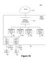
- FIG. 1Ashows a window control system 103 , and associated windows 111 , and other systems associated with a site.
- the figureillustrates the multiple interacting systems and the interfaces between them.
- the other systems that interface with the window system 103include third party systems 109 such as HVAC systems, security systems, and lighting systems.
- Window control system 103may also interface with building control service entities 105 such as NEST.
- system 103can interface with third party dashboards 107 , which may be used by consultants, etc. to present monitoring and/or performance information about one or more sites.
- the services provided by any of these systems( 103 , 105 , 107 , and 109 ) may be hosted at any of various locations.
- FIG. 1Ashows the logical positions at which APIs may exist between the entities. Firewalls can exist at any of these locations.
- “third party systems,” the “building control service entities,” and the “dashboards”are systems that are controlled by entities other than the entity that controls the window control system. However, this is not necessarily case.
- a third party systemmay simply be a system that has its own physical and/or logical infrastructure that is wholly or partially separate from the infrastructure(s) of the window control network.
- APIsallow external systems to view data collected by the window system. This includes data directly collected by the window system and also includes information relevant to the external systems and derived by the window system from the raw data it collects.
- APIsallow the window control system to access and control third-party systems.
- a lighting control systemmay provide an API that under certain conditions allows the window control system to access the lighting control system.
- the window control systememploys associated heuristics that permit or trigger the window control system to control aspects of the external system via an API.
- APIsallow external systems to control aspects of a window control system such as tinting of windows in a particular zone. As with the prior case, there may be particular conditions that trigger the allowance of the external system to access the functionality of the window control system.
- API interfaceis deployed or executes on a device or system remote from the window controller of a window control system.
- the APImay execute at the cloud level or master controller level in window control network.
- the local window controller(s)can locally communicate with third party systems and maintain comfort and service for an occupant.
- Sent informationmay include sensed data, predicted events, and site and device product and set up information.
- the interfacing system receiving this informationmay use this information to make decisions for controlling and otherwise managing its own equipment (not windows).
- the interfacing systemcan present this information in its own dashboard.
- the set up informationenables peer interfacing systems to provide services within the context of the window zones that the site owner has invested in setting up. For example, the site owner can set up zone information once and use the same zones in controlling lighting, heating, home appliances, etc. Zones for window control systems are described further in the context of PCT Patent Application No. PCT/US13/36456, filed Apr. 12, 2013, and incorporated herein by reference in its entirety.
- the window networkwill increase tint in the windows of zone Z by 30% at time X.
- the transitionwill take time T.
- the informationcan be provided per zone or with other set up information about the site. This aspects of 1 (e) apply.
- the interfacing system receiving this informationmay use this information to make decisions for controlling and otherwise managing its own equipment (not windows).
- the interfacing systemcan present this information in its own dashboard.
- the window networkuses its available information such as sensor data and current and future tint levels (per window, zone, etc.) to determine value added content useful to interacting, non-window, systems.
- the interfacing system receiving this informationmay use this information to make decisions for controlling and otherwise managing its own equipment (not windows).
- the interfacing systemcan present this information in its own dashboard.
- An interfacing systemsuch as a smart home appliance control service, a lighting system, or a security system may make tinting decisions based on its own needs and/or may send window tint level commands to the window network (without BACnet)
- the window control systemallows a smart thermostat (or other home appliance) service (e.g., NEST) to control of window tinting. This may be based on time of day, occupancy, and other types of information that the smart home appliance service has and uses. Similarly, embodiments allow remote control of thermostat and tinting.
- a smart thermostator other home appliance service (e.g., NEST)
- NESThome appliance service
- embodimentsallow remote control of thermostat and tinting.
- Embodimentsallow vacation mode in an external service to clear windows and allow in light to reduce likelihood of pipes freezing.
- Embodimentsallow a security company to darken home windows at certain times, and allow lights come on. Embodiments allow clearing of windows at 10 PM so neighbors can see in the house.
- a window control systemallows control of our window system such as dark in lock down and clear in a burglary.
- the window control functionalitycan be exposed per zone or with other set up information about the site. This aspects of 1 (e) apply.
- a lighting or air conditioning systemgives the window control system permission to control lighting or air conditioning based on tinting/clearing decisions.
- the window control systemmay exercise the control by making calls to the interfacing system's API (e.g., a thermostat control API).
- the interfacing systemmay subscribe to the window control system's API, and based on information provided from the window control system take action.
- a usermay have window tinting, room temperature, and lighting preferences that attach for the user.
- Such preferencesmay be triggered by the user's manual input, e.g., via a mobile device, or a system detecting the user's proximity, e.g., through communication with the user's worn digital sensor or smart mobile phone when the user enters a room or zone.
- FIG. 1BOne example of a window system appropriate for interfacing with other systems is depicted in FIG. 1B .
- the interfacing logic of a window system 11interfaces with multiple window controllers ( 1 - 3 ), sensors ( 1 - 2 ), and optionally other infrastructure associated with the switchable windows and controllers.
- the system 11may access the window controllers, sensors, and other infrastructure via a window controller network, which may be configured as described elsewhere herein.
- the system 11also interacts with multiple external systems or services 1 - 4 (e.g., a smart home appliance network service (e.g., NEST) or HVAC system) accessible through workstations, portable computers, mobile devices such as smartphones, and the like, each able to send and/or receive information relevant to its function.
- a service or systemmay be permitted access to only a subset of the information available to the window system.
- System 11may be implemented in various hardware and/or software configurations.
- system 11includes a data warehouse 13 , an analytics server 15 , and a report server 17 .
- the data warehouseinterfaces directly with the window controllers and/or sensors by, e.g., a window control network containing a hierarchy of controllers are described below with reference to FIGS. 1C-E .
- the data warehousestores data from these features in a relational database or other data storage arrangement.
- the datais stored in database or other data repository such as an Oracle DB, a Sequel DB, or a custom designed database.
- Data warehouse 13may obtain information from any of a number of sensor and controller types such as those described elsewhere herein.
- analytics server 15 and report server 17interface with the external systems to provide services and reports, respectively.
- the report serverruns Tableau, Jump, Actuate (Open Text), or a custom designed report generator.
- data warehouse 13 and analytics server 15each provide information to report server 17 .
- Communication between data warehouse 13 and analytics server 15is bidirectional.
- the interface with the external services and/or systemsmay be made via a communications interface 125 configured with logic for using APIs for each of the external services/systems.
- the communications between themmay be bidirectional or monodirectional.
- the window intelligence systemmay interface with the external systems/services via a wireless connection or a cable connection implemented in communications block 125 .
- a window network systemswill include multiple switchable optical devices, each directly controlled by a controller, multiple sensors such as illumination sensors, and one or more higher level controllers such as network controllers and master controllers.
- the window intelligence system 11is implemented in the “cloud”.
- the systemcan be centralized or distributed and can be accessed from anywhere using client application by authorized personnel.
- the various components of the systemmay be located together or apart in one or more sites, a location remote from all sites and/or in the cloud. Additional features, functions, modules, etc. of the system 11 may include a data and event reporter and a data and event log and/or a database.
- a window intelligence systemmay provide many types of services such as any one or more of the following services:
- the changes and comparisons described herecan be produced from data collected at, e.g., the network controller level. Historical data (days, weeks, months, years) is preserved in the window intelligence system, and such data can be used for comparison. With such data, variations due to temperature can be identified and ignored, if appropriate.
- the various changes, along or in combination,may provide a signature of a problem in a window, a controller, a sensor, etc. Any one or more of the foregoing parameters may identify an increase in impedance at any position from the power supply to (and including) the switchable device.
- This pathmay include the switchable device, a bus bar connected to the device, a lead attach to the bus bar, a connector to the lead attach or IGU, a group of wires (sometimes called a “pigtail”) between the connector (or IGU) and the power supply.
- a change in any or more of parameters 1a-1emay indicate corrosion caused by water in a window frame. A model using a combination of these parameters may recognize the signature of such corrosion and accurately report this issue remotely.
- the windows, controllers, and/or sensorshave their performance or response checked at an initial point in time and thereafter rechecked repeatedly. In some cases, recent performance/response measurements are compared with earlier performance/response measurements to detect trends, deviations, stability, etc. If necessary, adjustments can be made or service can be provided to address trends or deviations detected during comparisons.
- the collection of relevant parameters for a window, sensor, or controllermay serve as a “fingerprint” for the device. Such parameters include voltage response, current response, communications fidelity, etc. as described elsewhere herein.
- windows, sensors, and/or controllersare checked and optionally fingerprinted at the factory.
- a switchable windowmay go through a burn in procedures during which relevant parameters can be extracted.
- Windows exhibiting problemscan have their current performance compared against earlier fingerprints to optionally determine whether the problem developed after shipping/installation or during operation.
- Fingerprintscan also be generated, optionally automatically, when the devices are commissioned (e.g., installed at a site and initially detected and cataloged). Commissioning is described in PCT Patent Application No. PCT/US2013/036456, filed Apr. 12, 2013, and incorporated herein by reference in its entirety.
- a BMSis a computer-based control system installed at a site (e.g., a building) that can monitor and control the site's mechanical and electrical equipment such as ventilation, lighting, power systems, elevators, fire systems, and security systems.
- a BMSmay be designed or configured to communicate with a window system to receive control signals and communicate monitored information from systems at the site.
- a BMSconsists of hardware, including interconnections by communication channels to a computer or computers, and associated software for maintaining conditions in the site according to preferences set by the occupants, site manager, and/or window system manager.
- a BMSmay be implemented using a local area network, such as Ethernet.
- the softwarecan be based on, for example, internet protocols and/or open standards.
- One example of softwareis software from Tridium, Inc. (of Richmond, Va.).
- One communications protocol commonly used with a BMSis BACnet (building automation and control networks).
- a BMSis most common in a large building, and typically functions at least to control the environment within the building.
- a BMSmay control temperature, carbon dioxide levels, and humidity within a building.
- mechanical devicesthat are controlled by a BMS such as heaters, air conditioners, blowers, vents, and the like.
- a BMSmay turn on and off these various devices under defined conditions.
- a core function of a typical modern BMSis to maintain a comfortable environment for the building's occupants while minimizing heating and cooling costs/demand.
- a modern BMSis used not only to monitor and control, but also to optimize the synergy between various systems, for example, to conserve energy and lower building operation costs.
- a window control systeminterfaces with a BMS, where the window control system is configured to control one or more electrochromic windows or other tintable windows.
- each of the one or more tintable windowsincludes at least one all solid state and inorganic electrochromic device.
- each of the one or more tintable windowsincludes only all solid state and inorganic electrochromic devices.
- one or more of the tintable windowsare multistate electrochromic windows, as described in U.S. patent application Ser. No. 12/851,514, filed on Aug. 5, 2010, and entitled “Multipane Electrochromic Windows.”
- FIG. 1Cis a schematic diagram of an embodiment of a site network 1100 having a BMS that manages a number of systems of a building, including security systems, heating/ventilation/air conditioning (HVAC), lighting of the building, power systems, elevators, fire systems, and the like.
- Security systemsmay include magnetic card access, turnstiles, solenoid driven door locks, surveillance cameras, burglar alarms, metal detectors, and the like.
- Fire systemsmay include fire alarms and fire suppression systems including a water plumbing control.
- Lighting systemsmay include interior lighting, exterior lighting, emergency warning lights, emergency exit signs, and emergency floor egress lighting.
- Power systemsmay include the main power, backup power generators, and uninterrupted power source (UPS) grids.
- UPSuninterrupted power source
- window network 1102is depicted as a distributed network of window controllers including a master network controller, 1103 , intermediate network controllers, 1105 a and 1105 b , and end or leaf controllers 1110 . End or leaf controllers 1110 may be similar to window controller 450 described with respect to FIGS. 4 and 5 .
- master network controller 1103may be responsible for interfacing with the BMS, e.g., via an API, and each floor of building 1101 may have one or more intermediate network controllers 1105 a and 1105 b , while each window of the building has its own end or leaf controller 1110 .
- each of controllers 1110controls a specific tintable window of building 1101 .
- window network 1102 and/or master network controller 1103communicates with a window intelligence system or component thereof such as a data warehouse.
- Each of controllers 1110can be in a separate location from the tintable window that it controls, or can be integrated into the tintable window. For simplicity, only a few tintable windows of building 1101 are depicted as controlled by master window controller 1102 . In a typical setting there may be a large number of tintable windows in a building controlled by window network 1102 , which may be a distributed network of window controllers. In alternative embodiments, a single end controller which controls the functions of a single tintable window also falls within the scope of the embodiments disclosed herein.
- a BMScan provide, for example, enhanced: 1) environmental control, 2) energy savings, 3) security, 4) flexibility in control options, 5) improved reliability and usable life of other systems due to less reliance thereon and therefore less maintenance thereof, 6) information availability and diagnostics, 7) effective use of staff, and various combinations of these, because the tintable windows can be automatically controlled.
- a BMSmay not be present or a BMS may be present but may not directly communicate with a master network controller or communicate at a high level with a master network controller.
- a master network controllercan provide, for example, enhanced: 1) environmental control, 2) energy savings, 3) flexibility in control options, 4) improved reliability and usable life of other systems due to less reliance thereon and therefore less maintenance thereof, 5) information availability and diagnostics, 6) effective use of staff, and various combinations of these, because the tintable windows can be automatically controlled.
- maintenance on the BMSdoes not interrupt control of the tintable windows.
- a BMSmay be in communication with the window system, via an API, to receive control signals and transmit monitored data from one or more systems controlled by the BMS.
- FIG. 1Dis a block diagram of an alternative embodiment employing a network 1200 for a site (e.g., building).
- the network 1200may employ any number of different communication protocols, including BACnet.
- site network 1200includes a window system 1205 , a lighting control panel 1210 , a BMS 1215 , a security control system, 1220 , a user console, 1225 , a smart thermostat service or other home appliance service (e.g., NEST) 1227 .
- These different controllers and systems at the sitemay be used to receive input from and/or control a HVAC system 1230 , lights 1235 , security sensors 1240 , door locks 1245 , cameras 1250 , tintable windows 1255 , and thermostats 1257 of the site.
- a lighting control panelmay include circuits or other logic to control the interior lighting, the exterior lighting, the emergency warning lights, the emergency exit signs, and the emergency floor egress lighting.
- a lighting control panel(e.g., panel 1210 ) also may access occupancy sensors in the rooms of the site.
- BMS 1215may include a server that receives data from and issues commands to the other systems and controllers of site network 1200 .
- BMS 1215may receive data from and issue commands to each of the window controller 1205 , lighting control panel 1210 , and security control system 1220 .
- Security control system 1220may include magnetic card access, turnstiles, solenoid driven door locks, surveillance cameras, burglar alarms, metal detectors, and the like.
- User console 1225may be a computer terminal that can be used by the site manager to schedule operations of, control, monitor, optimize, and troubleshoot the different systems of the site.
- Software from Tridium, Inc.may generate visual representations of data from different systems for user console 1225 .
- Each of the different controlsmay control individual devices/apparatus.
- Window system 1205controls windows 1255 .
- Lighting control panel 1210controls lights 1235 .
- BMS 1215may control HVAC 1230 .
- Security control system 1220controls security sensors 1240 , door locks 1245 , and cameras 1250 . Data may be exchanged and/or shared between all of the different devices/apparatus and controllers that are part of site network 1200 .
- the systems of site network 1100 or site network 1200may run according to daily, monthly, quarterly, or yearly schedules.
- the lighting control system, the window control system, the HVAC, and the security systemmay operate on a 24 hour schedule accounting for when people are at the site during the work day.
- the sitemay enter an energy savings mode, and during the day, the systems may operate in a manner that minimizes the energy consumption of the site while providing for occupant comfort.
- the systemsmay shut down or enter an energy savings mode over a holiday period.
- Geographical informationmay include the latitude and longitude of a site such as, for example, a building. In the case of a building, geographical information also may include information about the direction that each side of the building faces. Using such information, different rooms on different sides of the building may be controlled in different manners. For example, for east facing rooms of the building in the winter, the window controller may instruct the windows to have no tint in the morning so that the room warms up due to sunlight shining in the room and the lighting control panel may instruct the lights to be dim because of the lighting from the sunlight.
- the west facing windowsmay be controllable by the occupants of the room in the morning because the tint of the windows on the west side may have no impact on energy savings. However, the modes of operation of the east facing windows and the west facing windows may switch in the evening (e.g., when the sun is setting, the west facing windows are not tinted to allow sunlight in for both heat and lighting).
- a sitesuch as, for example, the building 1101 in FIG. 1C , that includes a site network, tintable windows for the exterior windows (e.g., windows separating the interior of the building from the exterior of the building), and a number of different sensors.
- Light from exterior windows of a buildinggenerally has an effect on the interior lighting in the building about 20 feet or about 30 feet from the windows. That is, space in a building that is more that about 20 feet or about 30 feet from an exterior window receives little light from the exterior window. Such spaces away from exterior windows in a building are lit by lighting systems of the building.
- the temperature within a buildingmay be influenced by exterior light and/or the exterior temperature. For example, on a cold day and with the building being heated by a heating system, rooms closer to doors and/or windows will lose heat faster than the interior regions of the building and be cooler compared to the interior regions.
- the buildingmay include exterior sensors on the roof of the building.
- the buildingmay include an exterior sensor associated with each exterior window or an exterior sensor on each side of the building.
- An exterior sensor on each side of the buildingcould track the irradiance on a side of the building as the sun changes position throughout the day.
- outputs from exterior sensorsmay be input to a site network and/or window system. In some cases, these outputs may be provided as input to a local window controller. For example, in some embodiments, output signals from any two or more exterior sensors are received. In some embodiments, only one output signal is received, and in some other embodiments, three, four, five, or more outputs are received. These output signals may be received over a site network.
- the output signals received by sensor(s)include a signal indicating energy or power consumption by a heating system, a cooling system, and/or lighting within the building.
- the energy or power consumption of the heating system, the cooling system, and/or the lighting of the buildingmay be monitored to provide the signal indicating energy or power consumption.
- Devicesmay be interfaced with or attached to the circuits and/or wiring of the building to enable this monitoring.
- the power systems in the buildingmay be installed such that the power consumed by the heating system, a cooling system, and/or lighting for an individual room within the building or a group of rooms within the building can be monitored.
- Tint instructionscan be provided to change to tint of the tintable window to a determined level of tint.
- thismay include master network controller 1103 issuing commands to one or more intermediate network controllers 1105 a and 1105 b , which in turn issue commands to end controllers 1110 that control each window of the building.
- Master network controller 1103may issue commands based on commands received from a BMS and/or a window system.
- End controllers 1100may apply voltage and/or current to the window to drive the change in tint pursuant to the instructions.
- a site including tintable windowsmay be enrolled in or participate in a demand response program run by the utility or utilities providing power to the site.
- the programmay be a program in which the energy consumption of the site is reduced when a peak load occurrence is expected.
- the utilitymay send out a warning signal prior to an expected peak load occurrence. For example, the warning may be sent on the day before, the morning of, or about one hour before the expected peak load occurrence.
- a peak load occurrencemay be expected to occur on a hot summer day when cooling systems/air conditioners are drawing a large amount of power from the utility, for example.
- the warning signalmay be received by a BMS of a building, by the window system, or by window controllers configured to control the tintable windows in the building.
- This warning signalcan be an override mechanism that disengages the tinting control.
- the BMS or window systemcan then instruct the window controller(s) to transition the appropriate electrochromic device in the tintable windows to a dark tint level aid in reducing the power draw of the cooling systems in the building at the time when the peak load is expected.
- tintable windowse.g., electrochromic windows
- the exterior windows of the sitei.e., windows separating the interior from the exterior of a building
- tintable windows in a zonebeing instructed in a similar manner.
- groups of tintable windows on different floors of the building or different sides of a buildingmay be in different zones. In one case, on the first floor of the building, all of the east facing tintable windows may be in zone 1, all of the south facing tintable windows may be in zone 2, all of the west facing tintable windows may be in zone 3, and all of the north facing tintable windows may be in zone 4.
- all of the tintable windows on the first floor of the buildingmay be in zone 1, all of the tintable windows on the second floor may be in zone 2, and all of the tintable windows on the third floor may be in zone 3.
- all of the east facing tintable windowsmay be in zone 1
- all of the south facing tintable windowsmay be in zone 2
- all of the west facing tintable windowsmay be in zone 3
- all of the north facing tintable windowsmay be in zone 4.
- east facing tintable windows on one floorcould be divided into different zones. Any number of tintable windows on the same side and/or different sides and/or different floors of the building may be assigned to a zone.
- tintable windows in a zonemay be controlled by the same window controller. In some other embodiments, tintable windows in a zone may be controlled by different window controllers, but the window controllers may all receive the same output signals from sensors and use the same function or lookup table to determine the level of tint for the windows in a zone.
- tintable windows in a zonemay be controlled by a window controller or controllers that receive an output signal from a transmissivity sensor.
- the transmissivity sensormay be mounted proximate the windows in a zone.
- the transmissivity sensormay be mounted in or on a frame containing an IGU (e.g., mounted in or on a mullion, the horizontal sash of a frame) included in the zone.
- tintable windows in a zone that includes the windows on a single side of the buildingmay be controlled by a window controller or controllers that receive an output signal from a transmissivity sensor.
- a sensormay provide an output signal to a window controller to control the tintable windows of a first zone (e.g., a master control zone).
- the window controllermay also control the tintable windows in a second zone (e.g., a slave control zone) in the same manner as the first zone.
- another window controllermay control the tintable windows in the second zone in the same manner as the first zone.
- a site manager, occupants of rooms in the second zone, or other personmay manually instruct (using a tint or clear command or a command from a user console of a BMS, for example) the tintable windows in the second zone (i.e., the slave control zone) to enter a tint level such as a colored state (level) or a clear state.
- the tintable windows in the first zonei.e., the master control zone
- the tintable windows in the first zoneremain under control of the window controller receiving output from the transmissivity sensor.
- the second zonemay remain in a manual command mode for a period of time and then revert back to be under control of the window controller receiving output from the transmissivity sensor.
- the second zonemay stay in a manual mode for one hour after receiving an override command, and then may revert back to be under control of the window controller receiving output from the transmissivity sensor.
- a site manager, occupants of rooms in the first zone, or other personmay manually instruct (using a tint command or a command from a user console of a BMS, for example) the windows in the first zone (i.e., the master control zone) to enter a tint level such as a colored state or a clear state.
- the tintable windows in the second zonei.e., the slave control zone
- the first zonemay remain in a manual command mode for a period of time and then revert back to be under control of window controller receiving output from the transmissivity sensor.
- the first zonemay stay in a manual mode for one hour after receiving an override command, and then may revert back to be under control of the window controller receiving output from the transmissivity sensor.
- the tintable windows in the second zonemay remain in the tint level that they are in when the manual override for the first zone is received.
- the first zonemay remain in a manual command mode for a period of time and then both the first zone and the second zone may revert back to be under control of the window controller receiving output from the transmissivity sensor.
- any of the methods described herein of control of a tintable windowmay be used control the tint of a tintable window.
- references to a BMS in the above descriptioncan be replaced in some or all instances with references to a smart thermostat service or other home appliance service such as NEST.
- the communication between the window system and the BMS or home appliance servicecan be via an API as described above.
- Some features of this disclosuremay be implemented on a mesh network, such as the networks described in U.S. Provisional Patent Application No. 62/085,179, filed Nov. 26, 2014, previously incorporated by reference in its entirety.
- Devices on a mesh networkcan make use of information known by the network. For instance, where GPS coordinates of one or more windows are known, the other non-window devices can learn their exact locations based on the GPS data and the relative positions of all the other (window and non-window) devices. Because GPS typically does not work inside a building, direct GPS sensing of device positions inside of a building is difficult or impossible.
- such network devicesmay be populated into the map that is auto-generated.
- the map generated by the controller(s)may show the relative locations of all the windows and printers connected to the network.
- a building occupantcan use this map (e.g., loaded into a smartphone application, computer, etc.) to help them find their nearest printer or other relevant device on the mesh network.
- Occupancy sensors and HVAC componentsmay also be connected to or interface with the mesh network.
- the map generated by the controller(s)may show whether particular rooms are occupied based on information from the occupancy sensors, and may show other conditions (e.g., actual temperature, thermostat setting, humidity, status of lights, etc.) based on information from other HVAC components.
- the accuracy and precision of the mapare increased with an increased number of devices on the mesh network, since the additional devices provide further data for the system to piece together.
- Windows on the mesh networkmay be configured to interact with other devices on the mesh network, for example they interact via an API or directly with thermostats or other HVAC components. For instance, where a window or set of windows tint (thereby reducing the rate that heat enters the building through the window(s)), the window(s) may send a signal to a thermostat or other HVAC component to reduce the degree of cooling occurring through air conditioning. Similar signals may be sent to increase the degree of cooling through air conditioning, or to control a heating system. Additionally, information gleaned by the electrochromic window (e.g., through sensors, performance, etc.) may be shared with a thermostat or other HVAC component to help inform decisions made by the thermostat or HVAC.
- a thermostat or other HVAC componentmay be shared with a thermostat or other HVAC component to help inform decisions made by the thermostat or HVAC.
- the controllersmay have instructions to control the windows based on the sensed relative and exact positions/orientations of the various windows. For example, the controllers may have instructions to color east-facing windows early in the morning to prevent the sun from heating up the east-facing rooms, and to bleach the east-facing windows later in the afternoon when the sun is not shining directly into the east-facing rooms. Any control scheme may be used, and may be programmed into a controller by a user or installer, or may be pre-programmed by a manufacturer, vendor, etc. In some embodiments the window controllers are programmable in a similar manner as a thermostat (with the option of controlling a single window or multiple windows together).
- window controllers described hereininclude components for wired or wireless communication between the window controller, sensors, and separate communication nodes. Wireless or wired communications may be accomplished with a communication interface that interfaces directly with the window controller. Such interface could be native to the microprocessor or provided via additional circuitry enabling these functions.
- other systems of a site networkmay include components for wired or wireless communication between different system elements.
- a separate communication node for wireless communicationscan be, for example, another wireless window controller, an end, intermediate, or master window controller, a remote control device, a BMS, or a window system.
- Wireless communicationis used in the window controller for at least one of the following operations: programming and/or operating the tintable window 505 ( FIG. 5 ), collecting data from the tintable window 505 from the various sensors and protocols described herein, and using the tintable window 505 as a relay point for wireless communication.
- Data collected from tintable windows 505also may include count data such as number of times an EC device has been activated, efficiency of the EC device over time, and the like.
- wireless communicationis used to operate the associated tintable windows 505 , for example, via an infrared (IR), and/or radio frequency (RF) signal.
- the controllerwill include a wireless protocol chip, such as Bluetooth, EnOcean, Wi-Fi, ZigBee, and the like.
- Window controllersmay also have wireless communication via a network. Input to the window controller can be manually input by an end user at a wall switch, either directly or via wireless communication, or the input can be from a BMS of a site of which the tintable window is a component or from a window system managing system.
- wireless communicationis used to transfer data to and from each of a plurality of tintable windows via the distributed network of controllers, each having wireless communication components.
- master network controller 1103communicates wirelessly with each of intermediate network controllers 1105 a and 1105 b , which in turn communicate wirelessly with end controllers 1110 , each associated with an tintable window.
- Master network controller 1103may also communicate wirelessly with a BMS or with a window system. In one embodiment, at least one level of communication in the window controller is performed wirelessly.
- a master window controllermay communicate wirelessly to intermediate controllers via Wi-Fi or ZigBee, while the intermediate controllers communicate with end controllers via Bluetooth, ZigBee, EnOcean, or other protocol.
- window controllershave redundant wireless communication systems for flexibility in end user choices for wireless communication.
- FIG. 1Eis a block diagram of components of a window network system 1400 for controlling functions (e.g., transitioning to different tint levels) of one or more tintable windows at a site (e.g., building 1101 shown in FIG. 1C ), according to embodiments.
- System 1400may be one of the systems managed by a window system through a BMS (e.g., BMS 1100 shown in FIG. 1C ) or may be managed directly by a window system and/or operate independently of a BMS.
- BMSe.g., BMS 1100 shown in FIG. 1C
- System 1400includes a master window controller 1402 that can send control signals to the tintable windows to control its functions.
- System 1400also includes a network 1410 in electronic communication with master window controller 1402 .
- Control logic and instructions for controlling functions of the tintable window(s), and/or sensor datamay be communicated to the master window controller 1402 through the network 1410 .
- Network 1410can be a wired or a wireless network (e.g. a cloud network).
- network 1410may be in communication with a BMS (e.g., over an API) to allow the BMS to send instructions for controlling the tintable window(s) through network 1410 to the tintable window(s) in a building.
- the BMSmay be in communication with the window system to receive instructions for controlling the tintable window(s) from the window system.
- network 1410may be in communication with a window system to allow the window system to send instructions for controlling the tintable window(s) through network 1410 to the tintable window(s) in a building.
- the master window controller 1402 and/or the master network controller 1403are designed or configured to communicate with the window system or component thereof such as a data warehouse.
- System 1400also includes EC devices 400 of the tintable windows (not shown) and wall switches 1490 , which are both in electronic communication with master window controller 1402 .
- master window controller 1402can send control signals to EC device(s) to control the tint level of the tintable windows having the EC device(s).
- Each wall switch 1490is also in communication with EC device(s) and master window controller 1402 .
- An end usere.g., occupant of a room having the tintable window
- master window controller 1402is depicted as a distributed network of window controllers including a master network controller 1403 , a plurality of intermediate network controllers 1405 in communication with the master network controller 1403 , and multiple pluralities of end or leaf window controllers 1110 . Each plurality of end or leaf window controllers 1110 is in communication with a single intermediate network controller 1405 .
- master window controller 1402is illustrated as a distributed network of window controllers, master window controller 1402 could also be a single window controller controlling the functions of a single tintable window in other embodiments.
- the components of the system 1400 in FIG. 1 Dmay be similar in some respects to components described with respect to FIG. 1B .
- master network controller 1403may be similar to master network controller 1103 and intermediate network controllers 1405 may be similar to intermediate network controllers 1105 .
- Each of the window controllers in the distributed network of FIG. 1Emay include a processor (e.g., microprocessor) and a computer readable medium in electrical communication with the processor.
- each leaf or end window controller 1110is in communication with EC device(s) 400 of a single tintable window to control the tint level of that tintable window in the building.
- the leaf or end window controller 1110may be in communication with EC devices 400 on multiple lites of the IGU control the tint level of the IGU.
- each leaf or end window controller 1110may be in communication with a plurality of tintable windows.
- the leaf or end window controller 1110may be integrated into the tintable window or may be separate from the tintable window that it controls.
- Leaf and end window controllers 1110 in FIG. 1Emay be similar to the end or leaf controllers 1110 in FIG. 1C and/or may also be similar to window controller 450 described with respect to FIG. 5 .
- Each wall switch 1490can be operated by an end user (e.g., occupant of the room) to control the tint level and other functions of the tintable window in communication with the wall switch 1490 .
- the end usercan operate the wall switch 1490 to communicate control signals to the EC devices 400 in the associated tintable window.
- These signals from the wall switch 1490may override signals from master window controller 1402 in some cases. In other cases (e.g., high demand cases), control signals from the master window controller 1402 may override the control signals from wall switch 1490 .
- Each wall switch 1490is also in communication with the leaf or end window controller 1110 to send information about the control signals (e.g. time, date, tint level requested, etc.) sent from wall switch 1490 back to master window controller 1402 .
- wall switches 1490may be manually operated. In other cases, wall switches 1490 may be wirelessly controlled by the end user using a remote device (e.g., cell phone, tablet, etc.) sending wireless communications with the control signals, for example, using infrared (IR), and/or radio frequency (RF) signals. In some cases, wall switches 1490 may include a wireless protocol chip, such as Bluetooth, EnOcean, Wi-Fi, ZigBee, and the like. Although wall switches 1490 depicted in FIG. 1E are located on the wall(s), other embodiments of system 1400 may have switches located elsewhere in the room.
- a wireless protocol chipsuch as Bluetooth, EnOcean, Wi-Fi, ZigBee, and the like.
- Wireless communication between, for example, master and/or intermediate window controllers and end window controllersoffers the advantage of obviating the installation of hard communication lines. This is also true for wireless communication between window controllers and BMS.
- wireless communication in these rolesis useful for data transfer to and from electrochromic windows for operating the window and providing data to, for example, a BMS for optimizing the environment and energy savings in a building. Window location data as well as feedback from sensors are synergized for such optimization. For example, granular level (window-by-window) microclimate information is fed to a BMS in order to optimize the building's various environments.
- references to a BMS in the above descriptioncan be replaced in some or all instances with references to a smart thermostat service or other home appliance service such as NEST.
- the communication between the window system and the BMS or home appliance servicecan be via an API as described above.
- FIG. 2is a graph depicting voltage and current profiles associated with driving an electrochromic device from bleached to colored and from colored to bleached.
- FIG. 3is a graph depicting certain voltage and current profiles associated with driving an electrochromic device from bleached to colored.
- FIG. 2shows a complete current profile and voltage profile for an electrochromic device employing a simple voltage control algorithm to cause an optical state transition cycle (coloration followed by bleaching) of an electrochromic device.
- total current density (I)is represented as a function of time.
- the total current densityis a combination of the ionic current density associated with an electrochromic transition and electronic leakage current between the electrochemically active electrodes.
- Many different types electrochromic devicewill have the depicted current profile.
- a cathodic electrochromic materialsuch as tungsten oxide is used in conjunction with an anodic electrochromic material such as nickel tungsten oxide in counter electrode. In such devices, negative currents indicate coloration of the device.
- lithium ionsflow from a nickel tungsten oxide anodically coloring electrochromic electrode into a tungsten oxide cathodically coloring electrochromic electrode.
- electronsflow into the tungsten oxide electrode to compensate for the positively charged incoming lithium ions. Therefore, the voltage and current are shown to have a negative value.
- the depicted profileresults from ramping up the voltage to a set level and then holding the voltage to maintain the optical state.
- the current peaks 201are associated with changes in optical state, i.e., coloration and bleaching. Specifically, the current peaks represent delivery of the ionic charge needed to color or bleach the device. Mathematically, the shaded area under the peak represents the total charge required to color or bleach the device.
- the portions of the curve after the initial current spikes (portions 203 )represent electronic leakage current while the device is in the new optical state.
- a voltage profile 205is superimposed on the current curve.
- the voltage profilefollows the sequence: negative ramp ( 207 ), negative hold ( 209 ), positive ramp ( 211 ), and positive hold ( 213 ). Note that the voltage remains constant after reaching its maximum magnitude and during the length of time that the device remains in its defined optical state.
- Voltage ramp 207drives the device to its new the colored state and voltage hold 209 maintains the device in the colored state until voltage ramp 211 in the opposite direction drives the transition from colored to bleached states.
- a current capis imposed. That is, the current is not permitted to exceed a defined level in order to prevent damaging the device (e.g. driving ion movement through the material layers too quickly can physically damage the material layers).
- the coloration speedis a function of not only the applied voltage, but also the temperature and the voltage ramping rate.
- FIG. 3illustrates a voltage control profile in accordance with certain embodiments.
- a voltage control profileis employed to drive the transition from a bleached state to a colored state (or to an intermediate state).
- a similar but inverted profileis used to drive an electrochromic device in the reverse direction, from a colored state to a bleached state (or from a more colored to less colored state).
- the voltage control profile for going from colored to bleachedis a mirror image of the one depicted in FIG. 3 .
- V appThe voltage values depicted in FIG. 3 represent the applied voltage (Vapp) values.
- the applied voltage profileis shown by the dashed line.
- the current density in the deviceis shown by the solid line.
- V appincludes four components: a ramp to drive component 303 , which initiates the transition, a V drive component 313 , which continues to drive the transition, a ramp to hold component 315 , and a V hold component 317 .
- the ramp componentsare implemented as variations in V app and the V drive and V hold components provide constant or substantially constant Vapp magnitudes.
- the ramp to drive componentis characterized by a ramp rate (increasing magnitude) and a magnitude of V drive .
- the V drive componentis characterized by the value of V drive as well as the duration of V drive .
- the magnitude of V drivemay be chosen to maintain V eff with a safe but effective range over the entire face of the electrochromic device as described above.
- the ramp to hold componentis characterized by a voltage ramp rate (decreasing magnitude) and the value of V hold (or optionally the difference between V drive and V hold ). V app drops according to the ramp rate until the value of V hold is reached.
- the V hold componentis characterized by the magnitude of V hold and the duration of V hold . Actually, the duration of Vhold is typically governed by the length of time that the device is held in the colored state (or conversely in the bleached state). Unlike the ramp to drive, V drive , and ramp to hold components, the V hold component has an arbitrary length, which is independent of the physics of the optical transition of the device.
- Each type of electrochromic devicewill have its own characteristic components of the voltage profile for driving the optical transition. For example, a relatively large device and/or one with a more resistive conductive layer will require a higher value of Vdrive and possibly a higher ramp rate in the ramp to drive component. Larger devices may also require higher values of V hold .
- the values of each component of the applied voltage profileis set for a particular electrochromic device (having its own bus bar separation, resistivity, etc.) and does vary based on current conditions.
- the voltage profiledoes not take into account feedback such as temperature, current density, and the like.
- the ramp to drive component of the voltage profileis chosen to safely but rapidly induce ionic current to flow between the electrochromic and counter electrodes.
- the current in the devicefollows the profile of the ramp to drive voltage component until the ramp to drive portion of the profile ends and the V drive portion begins. See current component 301 in FIG. 3 .
- Safe levels of current and voltagecan be determined empirically or based on other feedback.
- the value of V driveis chosen based on the considerations described above. Particularly, it is chosen so that the value of V eff over the entire surface of the electrochromic device remains within a range that effectively and safely transitions large electrochromic devices.
- the duration of V drivecan be chosen based on various considerations. One of these ensures that the drive potential is held for a period sufficient to cause the substantial coloration of the device. For this purpose, the duration of V drive may be determined empirically, by monitoring the optical density of the device as a function of the length of time that Vdrive remains in place. In some embodiments, the duration of V drive is set to a specified time period. In another embodiment, the duration of V drive is set to correspond to a desired amount of ionic charge being passed. As shown, the current ramps down during V drive . See current segment 307 .
- Another considerationis the reduction in current density in the device as the ionic current decays as a consequence of the available lithium ions completing their journey from the anodic coloring electrode to the cathodic coloring electrode (or counter electrode) during the optical transition.
- the transitionis complete, the only current flowing across device is leakage current through the ion conducting layer.
- the ohmic drop in potential across the face of the devicedecreases and the local values of V eff increase.
- V effcan damage or degrade the device if the applied voltage is not reduced.
- another consideration in determining the duration of V driveis the goal of reducing the level of V eff associated with leakage current.
- V effBy dropping the applied voltage from Vdrive to Vhold, not only is V eff reduced on the face of the device but leakage current decreases as well. As shown in FIG. 3 , the device current transitions in a segment 305 during the ramp to hold component. The current settles to a stable leakage current 309 during V hold .
- FIG. 4depicts a block diagram of some components of a window controller 450 and other components of a window controller system of disclosed embodiments.
- FIG. 4is a simplified block diagram of a window controller, and more detail regarding window controllers can be found in U.S. patent application Ser. Nos. 13/449,248 and 13/449,251, both naming Stephen Brown as inventor, both titled “CONTROLLER FOR OPTICALLY-SWITCHABLE WINDOWS,” and both filed on Apr. 17, 2012, and in U.S. patent Ser. No. 13/449,235, titled “CONTROLLING TRANSITIONS IN OPTICALLY SWITCHABLE DEVICES,” naming Stephen Brown et al. as inventors and filed on Apr. 17, 2012, all of which are hereby incorporated by reference in their entireties.
- the illustrated components of the window controller 450include a window controller 450 having a microprocessor 410 or other processor, a power width modulator (PWM) 415 , a signal conditioning module 405 , and a computer readable medium 420 (e.g., memory) having a configuration file 422 .
- Window controller 450is in electronic communication with one or more electrochromic devices 400 in an electrochromic window through network 425 (wired or wireless) to send instructions to the one or more electrochromic devices 400 .
- the window controller 450may be a local window controller in communication through a network (wired or wireless) to a master window controller.
- a sitemay be a building having at least one room having an electrochromic window between the exterior and interior of a building.
- One or more sensorsmay be located to the exterior of the building and/or inside the room.
- the output from the one or more sensorsmay be input to the signal conditioning module 405 of the window controller 450 .
- the output from the one or more sensorsmay be input to a BMS or to a window system.
- the sensors of depicted embodimentsare shown as located on the outside vertical wall of the building, this is for the sake of simplicity, and the sensors may be in other locations, such as inside the room or on other surfaces to the exterior, as well.
- two or more sensorsmay be used to measure the same input, which can provide redundancy in case one sensor fails or has an otherwise erroneous reading.
- FIG. 5depicts a schematic diagram of a room 500 having a tintable window 505 with at least one electrochromic device.
- the tintable window 505is located between the exterior and the interior of a building, which includes the room 500 .
- the room 500also includes a window controller 450 connected to and configured to control the tint level of the tintable window 505 .
- An exterior sensor 510is located on a vertical surface in the exterior of the building.
- an interior sensormay also be used to measure the ambient light in room 500 .
- an occupant sensormay also be used to determine when an occupant is in the room 500 .
- Exterior sensor 510is a device, such as a photosensor, that is able to detect radiant light incident upon the device flowing from a light source such as the sun or from light reflected to the sensor from a surface, particles in the atmosphere, clouds, etc.
- the exterior sensor 510may generate a signal in the form of electrical current that results from the photoelectric effect and the signal may be a function of the light incident on the sensor 510 .
- the devicemay detect radiant light in terms of irradiance in units of watts/m 2 or other similar units.
- the devicemay detect light in the visible range of wavelengths in units of foot candles or similar units. In many cases, there is a linear relationship between these values of irradiance and visible light.
- Irradiance values from sunlightcan be predicted based on the time of day and time of year as the angle at which sunlight strikes the earth changes.
- Exterior sensor 510can detect radiant light in real-time, which accounts for reflected and obstructed light due to buildings, changes in weather (e.g., clouds), etc. For example, on cloudy days, sunlight would be blocked by the clouds and the radiant light detected by an exterior sensor 510 would be lower than on cloudless days.
- Output from the one or more exterior sensors 510could be compared to one another to determine, for example, if one of exterior sensors 510 is shaded by an object, such as by a bird that landed on exterior sensor 510 .
- a single sensor or a few sensorsmay be employed to determine the current level of radiant light from the sun impinging on the building or perhaps one side of the building.
- a cloudmay pass in front of the sun or a construction vehicle may park in front of the setting sun. These will result in deviations from the amount of radiant light from the sun calculated to normally impinge on the building.
- Exterior sensor 510may be a type of photosensor.
- exterior sensor 510may be a charge coupled device (CCD), photodiode, photoresistor, or photovoltaic cell.
- CCDcharge coupled device
- photodiodephotodiode
- photoresistorphotoresistor
- photovoltaic cellOne of ordinary skill in the art would appreciate that future developments in photosensor and other sensor technology would also work, as they measure light intensity and provide an electrical output representative of the light level.
- output from exterior sensor 510may be input to a BMS or window system.
- the inputmay be in the form of a voltage signal.
- the BMS or window systemmay process the input and pass an output signal with tinting instructions to the window controller 450 directly or through a master window controller 1102 (shown in FIG. 1C ).
- the tint level of the tintable window 505may be determined based on configuration information, override values, etc.
- Window controller 450then instructs the PWM 415 , to apply a voltage and/or current to tintable window 505 to transition to the desired tint level.
- window controller 450can instruct the PWM 415 , to apply a voltage and/or current to tintable window 505 to transition it to any one of four or more different tint levels.
- tintable window 505can be transitioned to at least eight different tint levels described as: 0 (lightest), 5, 10, 15, 20, 25, 30, and 35 (darkest). The tint levels may linearly correspond to visual transmittance values and solar gain heat coefficient (SGHC) values of light transmitted through the tintable window 505 .
- SGHCsolar gain heat coefficient
- the lightest tint level of 0may correspond to an SGHC value of 0.80
- the tint level of 5may correspond to an SGHC value of 0.70
- the tint level of 10may correspond to an SGHC value of 0.60
- the tint level of 15may correspond to an SGHC value of 0.50
- the tint level of 20may correspond to an SGHC value of 0.40
- the tint level of 25may correspond to an SGHC value of 0.30
- the tint level of 30may correspond to an SGHC value of 0.20
- the tint level of 35 (darkest)may correspond to an SGHC value of 0.10.
- the BMS or window system in communication with the window controller 450 or a master window controller in communication with the window controller 450may employ any control logic to determine a desired tint level based on signals from the exterior sensor 510 and/or other input.
- the window controller 415can instruct the PWM 460 to apply a voltage and/or current to electrochromic window 505 to transition it to the desired tint level.
- references to a BMS in the above descriptioncan be replaced in some or all instances with references to a smart thermostat service or other home appliance service such as NEST.
- FIG. 6is a flowchart showing exemplary control logic for a method of controlling one or more tintable windows at a site, according to embodiments.
- the control logicuses one or more of the Modules A, B, and C to calculate tint levels for the tintable window(s) and sends instructions to transition the tintable window(s).
- the calculations in the control logicare run 1 to n times at intervals timed by the timer at step 610 .
- nis the number of recalculations performed and n can be at least 1.
- the logic calculationscan be done at constant time intervals in some cases. In one cases, the logic calculations may be done every 2 to 5 minutes. However, tint transition for large pieces of electrochromic glass can take up to 30 minutes or more. For these large windows, calculations may be done on a less frequent basis such as every 30 minutes.
- Modules A, B, and Care used in the illustrated embodiment, one or more other logic modules can be used in other embodiments.
- logic Modules A, B, and Cperform calculations to determine a tint level for each electrochromic window 505 at a single instant in time t i . These calculations can be performed by the window controller 450 or by a window system.
- the control logicpredictively calculates how the window should transition in advance of the actual transition.
- the calculations in Modules A, B, and Ccan be based on a future time around or after transition is complete.
- the future time used in the calculationsmay be a time in the future that is sufficient to allow the transition to be completed after receiving the tint instructions.
- the controllercan send tint instructions in the present time in advance of the actual transition. By the completion of the transition, the window will have transitioned to a tint level that is desired for that time.
- the control logicallows for certain types of overrides that disengage the algorithm at Modules A, B, and C and define override tint levels at step 640 based on some other consideration.
- One type of overrideis a manual override. This is an override implemented by an end user who is occupying a room and determines that a particular tint level (override value) is desirable. There may be situations where the user's manual override is itself overridden.
- An example of an overrideis a high demand (or peak load) override, which is associated with a requirement of a utility that energy consumption in the building be reduced.
- the buildingmay override the tint level from the control logic to ensure that all windows have a particularly high level of tinting.
- an overridemay be if there is no occupant in the room, for example, over a weekend in a commercial office building. In these cases, the building may disengage one or more Modules that relate to occupant comfort.
- an overridemay be that all the windows may have a high level of tinting in cold weather or all the windows may have a low level of tinting in warm weather.
- instructions with the tint levelsare transmitted over a site network to window controller(s) in communication with electrochromic device(s) in one or more tintable windows 505 in the building.
- the transmission of tint levels to all window controllers of a buildingmay be implemented with efficiency in mind. For example, if the recalculation of tint level suggests that no change in tint from the current tint level is required, then there is no transmission of instructions with an updated tint level.
- the buildingmay be divided into zones based on window size.
- the control logicmay calculate a single tint level for each zone.
- the control logicmay recalculate tint levels for zones with smaller windows more frequently than for zones with larger windows.
- the logic in FIG. 6 for implementing the control methods for multiple tintable windows 505 in an entire sitecan be on a single device, for example, a single master window controller. This device can perform the calculations for each and every window in the site and also provide an interface for transmitting tint levels to one or more electrochromic devices in individual tintable windows 505 .
- control logicmay determine how an end user (e.g. occupant) tries to override the algorithm at particular times of day and makes use of this information in a more predictive manner to determine desired tint levels.
- the end usermay be using a wall switch to override the tint level provided by the predictive logic at a certain time each day to an override value.
- the control logicmay receive information about these instances and change the control logic to change the tint level to the override value at that time of day.
- a mechanical shademay, for example, include an array of microelectromechanical systems (MEMS) devices or other electromechanical systems (EMS) devices.
- MEMSmicroelectromechanical systems
- EMSelectromechanical systems
- Windows having a combination of electrochromic devices and EMS systems devicescan be found in PCT international application PCT/US2013/07208, titled “MULTI-PANE WINDOWS INCLUDING ELECTROCHROMIC DEVICES AND ELECTROMECHANICAL SYSTEMS DEVICES,” filed on Nov. 26, 2012, which is hereby incorporated by reference in its entirety.
- Mechanical shadestypically have different power requirements than certain optically switchable devices such as electrochromic devices. For example, while certain electrochromic devices require a few volts to operate, mechanical shades may in some instances require larger voltages
- Microblinds and microshuttersare examples of types of EMS devices. Some examples of microblinds and microshutters, and their methods of fabrication are described respectively in U.S. Pat. Nos. 7,684,105 and 5,579,149, both of which are hereby incorporated by reference in their entirety.
- a mechanical shademay be an array of EMS devices, where each EMS device including a portion (e.g., a hinge or an anchor) attached to the substrate and a mobile portion.
- the mobile portionWhen actuated by electrostatic forces, the mobile portion may move and obscure the substrate. In the unactuated state, the mobile portion may expose the substrate.
- the mobile portionIn the example of some microblinds, the mobile portion may be an overhanging portion of a material layer that curls when actuated by electrostatic forces.
- the mobile portioncan rotate or curl when actuated.
- the EMS devicesmay be actuated and controlled by electrostatic control means. In the example of microshutters, the electrostatic control means may control the angle of rotation or curl to different states.
- the substrate with the array of EMS devicesmay also include a conductive layer.
- the microblindsare fabricated using a thin layer(s) under controlled stress.
- each EMS devicehas two states, an actuated state and an unactuated state.
- the actuated statemay render the array of EMS devices substantially opaque and the unactuated state may render the array of EMS devices substantially transparent, or vice versa.
- the actuated and unactuated statesmay also switch between substantially reflective (or absorptive) and substantially transparent, for example. Other states are also possible when the array of EMS devices is in an actuated or unactuated state.
- microshuttersa type of MEMS device
- some arrays of EMS devicesmay have three, four, or more states that are able to be transitioned to.
- the EMS devicescan modify visible and/or infrared transmission.
- the EMS devicesmay reflect in some cases, may be absorptive in other cases, and in yet other embodiments may provide both reflective and absorptive properties.
- the EMS devicesmay be operated at variable speeds, e.g., to transition from a high transmission state to a low-transmission state, or a no-transmission state.
- the EMS devicesmay be used in conjunction with an electrochromic device (or other optically switchable device) as a temporary light blocking measure, e.g., to block light until the associated electrochromic device has transitioned to a lower transmissivity state or a higher transmissivity state.
Landscapes
- Engineering & Computer Science (AREA)
- Physics & Mathematics (AREA)
- General Physics & Mathematics (AREA)
- Theoretical Computer Science (AREA)
- Business, Economics & Management (AREA)
- Software Systems (AREA)
- General Engineering & Computer Science (AREA)
- Tourism & Hospitality (AREA)
- Structural Engineering (AREA)
- Automation & Control Theory (AREA)
- Nonlinear Science (AREA)
- Civil Engineering (AREA)
- Health & Medical Sciences (AREA)
- Strategic Management (AREA)
- Architecture (AREA)
- Primary Health Care (AREA)
- Marketing (AREA)
- Human Resources & Organizations (AREA)
- General Health & Medical Sciences (AREA)
- Economics (AREA)
- General Business, Economics & Management (AREA)
- Optics & Photonics (AREA)
- Human Computer Interaction (AREA)
- Signal Processing (AREA)
- Computer Networks & Wireless Communication (AREA)
- Selective Calling Equipment (AREA)
- Circuit Arrangement For Electric Light Sources In General (AREA)
- Electrochromic Elements, Electrophoresis, Or Variable Reflection Or Absorption Elements (AREA)
- Air Conditioning Control Device (AREA)
- Medicines Containing Material From Animals Or Micro-Organisms (AREA)
- Peptides Or Proteins (AREA)
- Prostheses (AREA)
- Burglar Alarm Systems (AREA)
Abstract
Description
- 1. A window control system provides raw collected information and/or processed information derived from the raw information to an interfacing system:
- Temperature—interior or external
- Sensed solar irradiance—directional
- Interior photosensors—glass or mullion
- Solar heat gain,
- Occupancy—IR, motion,—number of persons in the room
- Solar calculator (angle, intensity)—azimuthally, inclination
- Weather—cloud cover
- Snow on the ground—frozen lake
- Site and device set up information—Examples follow:
- GET/sites present metadata about sites, including applicable ip addresses
- GET/site/{ site_id} presents metadata about a specific site and the zone groups and zones within that site
- GET/zone/{zone_id} presets information about a specific zone, what devices and services are available, etc.
- 2. The window control system provides its own window tinting information (current and/or future) to an interfacing system:
- 3. A window control system provides value added content to an interfacing system:
- For HVAC, the amount of energy coming through the façade as sensed and/or predicted with a solar calculator. Granularity (per floor, per direction)—based on time as well. Calculate number of BTUs that they need to provide. Heating/cooling BTUs required for a façade or window opening.
- For a smart home appliance service—provide temperature gradient determined from temperature at thermostat and temperature at a window. Large difference might suggest that the interfacing system needs to bump up the heating (or cooling) for comfort.
- For a lighting control systems—provide suggested lighting levels determined by, e.g., how much light from windows and at what direction, solar calculator, environmental conditions (clouds, snow, reflection), occupancy, user initiated tinting decisions, etc.
- 4. The window control system exposes its functionality:
- 5. A window control system controls the equipment of an interfacing system:
- Heat is generated by electrical equipment such as televisions, computers, and office equipment. Sensing plug loads (office equipment, etc.) may be enabled by the site providing load sensors (real-time power monitors for each area of interest). These sensors may be part of the HVAC or lighting system. In certain embodiments, the window control systems accesses devices from such systems (via an API) and gathers information from them, then combines that information with other data it collects and uses the result to control the interfacing system's devices. For example the window system may read plug loads and combine it with the incident energy striking the façade and the current HVAC heating/cooling BTUs to optimize energy use in that location.
- The window control system instructs the thermostat to back off air conditioning when the window system has reduced or will begin reducing heat load through window tinting.
- Sensors in window control system detect occupancy by, e.g., BLE (Blue Tooth Low Energy) beacons deployed in window controllers and/or wall interfaces. With this information, the window control system instructs a thermostat to change its mode from away mode to home mode.
- 6. A user-customizable system interfaces with the window control system and other peer systems. The user-customizable system presents a user's preferences to control devices on site systems and causes them to enter states pre-defined by the user.
- a. Customer service—the system can be configured to note when data from a switchable device, a sensor, and/or a controller indicates a problem in an external system. In response, service personnel may be summoned to correct the problem or communicate that there is a problem. In some instances, potential issues are flagged and resolved before they become apparent to the external system. The window system may be configured to autocorrect problems with external systems. Unless stated otherwise, any of the problems, issues, errors, etc. described herein can be autocorrected using heuristics in the window control system.
Alert notifications may be sent when issues are detected.
The system may also provide look ahead data to external systems such as HVAC systems, thereby enabling such systems to enhance user comfort and/or save energy. - b. Customize the installation based on observed usage trends. User preferences may be incorporated in a program over time. As an example, the window system may determine how an end user (e.g. occupant) tries to override a heating or lighting control algorithm at particular times of day and uses this information to predict future behavior of the user. It may inform the relevant external system and/or modify the window control algorithm to set tint levels according to the learned user preference.
- c. Deploy learned approaches to other external systems or installations (e.g., how to best tint windows, light windows, heat/cool rooms when an afternoon thunderstorm approaches). There are benefits achieved in using the collective experience and information from an installed base of switchable device networks. For example, it helps to fine tune control algorithms, customize window/network products for a particular market segment, and/or test new ideas (e.g., control algorithms, sensor placement).
- d. Energy consulting services. Such services may use information about a building such as energy consumption of a building, window tinting decisions, solar radiation flux (e.g., on different sides of a building), local weather information (cloud cover, temperature, etc.), etc. Such information may be provided in various time increments, e.g., months, weeks, days, hours, minutes, etc. Energy consulting services may use such information in developing analyses and/or recommendations for the building(s) from which the information was obtained and/or similar building (e.g., nearby buildings, buildings in similar climates, or at similar latitudes). Also, energy consulting services may use the information to provide analyses and/or recommendations to energy infrastructure entities such as utilities, HVAC equipment suppliers, campuses, entities that provide control services to power grids, etc.
- e. Vendors who market information. Some vendors integrate information from various sources and bundle useful tags customized to buyer needs.
Data Monitored
The following description presents examples of some types of site information that may be monitored by a window system. The information may be provided from various sources such as voltage and/or current versus time data for individual switchable devices, sensor output data versus time, communications and network events and logs for controller networks, etc. The time variable may be associated with external events such as solar position, weather, etc., as well as time of day or calendar day. Information with a periodic component may be analyzed in the frequency domain as well as the time domain.
- a. Customer service—the system can be configured to note when data from a switchable device, a sensor, and/or a controller indicates a problem in an external system. In response, service personnel may be summoned to correct the problem or communicate that there is a problem. In some instances, potential issues are flagged and resolved before they become apparent to the external system. The window system may be configured to autocorrect problems with external systems. Unless stated otherwise, any of the problems, issues, errors, etc. described herein can be autocorrected using heuristics in the window control system.
- a. Changes in peak current. This is sometimes produced during application of a ramp to drive voltage for producing an optical transition. See
FIGS. 2 and 3 . - b. Changes in hold (leakage) current. This may be observed at an end state of a switchable device. A rate of increasing leakage current may correlate with the likelihood that a short has developed in the device. Sometimes a short causes an undesirable blemish such as a halo in the device.
- c. Change in voltage compensation required. Voltage compensation is the change in voltage required to account for the voltage drop in the conductive path from the power supply to the switchable device.
- d. Change in total charge transferred. This may be measured over a period of time and/or during a certain state of the switchable device (e.g., during drive or during hold).
- e. Change in power consumption. Power consumption may be calculated by (I*V) per window or controller.
- f. Comparison with other WC (window controllers) on the same façade with identical loads. This allows the monitoring system to determine that a particular controller has an issue, rather than a particular device controlled by the controller. For example, a window controller may be connected to five insulated glass units, each exhibiting the same issue. Because it is unlikely that five devices will all suffer from the same issue, the monitoring system may conclude that the controller is to blame.
- g. Instances of abnormal profiles: e.g., double tinting/double clearing. Double tinting/clearing refers to a situation where a normal drive cycle (voltage and/or current profile) is applied and it is found that the switchable device has not switched, in which case a second drive cycle must be conducted.
- h. Switching characteristics vs. external weather. At certain temperatures or weather conditions, the monitoring system expects particular switching results or performance. Deviations from the expected response suggest an issue with a controller, a switchable device, and/or a sensor.
- a. Changes in peak current. This is sometimes produced during application of a ramp to drive voltage for producing an optical transition. See
- a. Any window controller getting out of sync with zone—may be due to communication issues. Example: If there are multiple controllers in a zone, and one of these controllers does behave as expected, the window system may conclude that the aberrant controller is not receiving or following commands over a communications network. The system can take action to isolate the source of the problem and correct it.
- b. Longest switching time for the zone and adjustments to make all glass switch at the same rate. The system may identify a particular switchable device that is not switching at a desired rate or an expected rate. Without replacing or modifying the device, the window system may modify the switching algorithm so that the device switches at the expected rate. For example, if a device is observed to switch too slowly, its ramp to drive or drive voltage may be increased. This can be done remotely.
- a. Any change in frequency of communication errors—increase in noise or device degradation. The received communications from a controller may be slowed or stopped. Or, the send communications may not be acknowledged or acted upon.
- b. Connection degradation if pigtail starts showing up as disconnected. In certain embodiments, a connector provides a signal indicating that it is becoming disconnected. A window controller may receive such signals, which can be logged at the window system.
- a. Any degradation over time. This may be manifest as a signal magnitude reduction. It may be caused by various factors including damage to the sensor, dirt on the sensor, an obstruction appearing in front of the sensor, etc.
- b. Correlation with external weather. Normally, the window system will assume that the photo sensor output should correlate with the weather.
- c. Comparison with zone state change to ensure Intelligence working correctly. The window system normally expects that the zone will change state when its photosensor output meets certain state-change criteria. For example, if the sensor indicates a transition to sunny conditions, the switchable devices in the zone should tint. In certain embodiments, there are one or more photosensors per zone.
- d. Any changes in surroundings after commissioning. As an example, a tree grows in front of the sensor or a building is constructed in front of a sensor. Such changes in surroundings may be evidenced by multiple sensors affected by the changes being similarly affected (e.g., their photo sensor outputs go down at the same time). Among other purposes, commissioning provides information about the deployment of sensors, controllers, and/or switchable optical devices in a site. Commissioning is further described in PCT Application No. PCT/US2013/036456, filed Apr. 12, 2013, which is incorporated herein by reference in its entirety.
- e. Data from a central or multifunctional sensor. In some embodiments, a building has a multifunctional sensor providing sensed data for a variety of parameters relevant to window tinting or other building management. Examples of individual sensors that may be included in such multifunctional sensor include temperature sensors, directional photosensors (e.g., three or more photosensors oriented in different azimuthal and/or altitudinal directions), humidity sensors, etc. The photosensors may capture visible light, IR radiation, UV radiation, or any combination thereof. In certain embodiments, the multifunctional sensor provides weather related data. In one example, the sensor is a ring sensor as described in U.S. Patent Application No. 62/238,100, filed Oct. 6, 2015, and incorporated herein by reference in its entirety.
- a. Overrides by zone—further tuning of control algorithms for the zone. The window system may learn the requirements of a particular site and adapt its learning algorithm to address the requirements. Various types of adaptive learning are described in PCT Application No. PCT/US2013/036456, filed Apr. 12, 2013, which was previously incorporated herein by reference in its entirety.
- b. iOS vs. Wall Switch overrides—consumer preference. When overrides are observed, the monitoring system may note which type of device initiated the override, a wall switch or a mobile device. More frequent use of wall switches may indicate a training issue or a problem with the window application on the mobile device.
- c. Time/Frequency of various states—usefulness of each state. When multiple tint states are available, and some are underused, it may indicate to the remote monitoring system that there is an issue with a particular state. The system may change the transmissivity or other characteristic of the state.
- d. Variation by market segment. The frequency of use (popularity) of certain states or other properties of a site's switching characteristics may correlate with a market segment. When a window system learns this, it may develop and provide market-specific algorithms. Examples of market segments include airports, hospitals, office buildings, schools, government buildings, etc.
- e. Total number of transitions—Expected number of cycles over warranty period and life by market segment. This may provide in situ lifecycle information.
- a. Energy saved by zone by season, total system energy saving by season. The window system may determine energy savings to identify algorithms, device types, structures, etc. that provide improvements. Provide performance information and recommendations to external systems such as HVAC systems and smart thermostat service or other home appliance services (e.g., NEST).
- b. Provide advanced energy load information to AC system by zone. Buildings have large thermal masses, so air conditioning and heating do not take effect immediately. Using a solar calculator or other predictive tools (describe elsewhere herein), the window system can provide advance notice to HVAC systems or NEST so they can begin a transition early. It may be desirable to provide this information by zone.
- a. In certain embodiments, windows and/or associated structures (e.g., controllers, IGU spacers, and frames) have antennas attached or fabricated thereon. Examples of such window antennas are described in PCT Patent Application No. PCT/US2015/062387, filed Nov. 24, 2015, and incorporated herein by reference in its entirety.
- a. A window antenna can provide the location of occupants and/or visitors, who carry communication enabled devices such as mobile phones
- b. presence of intruders and other security related information (e.g., when a window has a privacy setting activated).
- c. bandwidth consumed or available on services provided by the window antennas
Claims (18)
Priority Applications (7)
| Application Number | Priority Date | Filing Date | Title |
|---|---|---|---|
| US15/910,936US10387221B2 (en) | 2014-12-08 | 2018-03-02 | Multiple interacting systems at a site |
| US16/523,624US10956231B2 (en) | 2014-12-08 | 2019-07-26 | Multiple interacting systems at a site |
| US16/555,377US10949267B2 (en) | 2014-12-08 | 2019-08-29 | Multiple interacting systems at a site |
| US17/171,667US11436061B2 (en) | 2014-12-08 | 2021-02-09 | Multiple interacting systems at a site |
| US17/869,725US11740948B2 (en) | 2014-12-08 | 2022-07-20 | Multiple interacting systems at a site |
| US17/989,603US11948015B2 (en) | 2014-12-08 | 2022-11-17 | Multiple interacting systems at a site |
| US18/428,413US12260269B2 (en) | 2014-12-08 | 2024-01-31 | Multiple interacting systems at a site |
Applications Claiming Priority (4)
| Application Number | Priority Date | Filing Date | Title |
|---|---|---|---|
| US201462088943P | 2014-12-08 | 2014-12-08 | |
| PCT/US2015/064555WO2016094445A1 (en) | 2014-12-08 | 2015-12-08 | Multiple interacting systems at a site |
| US201715534175A | 2017-06-08 | 2017-06-08 | |
| US15/910,936US10387221B2 (en) | 2014-12-08 | 2018-03-02 | Multiple interacting systems at a site |
Related Parent Applications (3)
| Application Number | Title | Priority Date | Filing Date |
|---|---|---|---|
| US15/534,175ContinuationUS10514963B2 (en) | 2014-12-08 | 2015-12-08 | Multiple interacting systems at a site |
| PCT/US2015/064555ContinuationWO2016094445A1 (en) | 2011-03-16 | 2015-12-08 | Multiple interacting systems at a site |
| US15/623,235ContinuationUS10409652B2 (en) | 2014-12-08 | 2017-06-14 | Multiple interacting systems at a site |
Related Child Applications (1)
| Application Number | Title | Priority Date | Filing Date |
|---|---|---|---|
| US16/523,624ContinuationUS10956231B2 (en) | 2014-12-08 | 2019-07-26 | Multiple interacting systems at a site |
Publications (2)
| Publication Number | Publication Date |
|---|---|
| US20180189117A1 US20180189117A1 (en) | 2018-07-05 |
| US10387221B2true US10387221B2 (en) | 2019-08-20 |
Family
ID=56108076
Family Applications (7)
| Application Number | Title | Priority Date | Filing Date |
|---|---|---|---|
| US15/534,175ActiveUS10514963B2 (en) | 2014-12-08 | 2015-12-08 | Multiple interacting systems at a site |
| US15/623,235Active2036-05-30US10409652B2 (en) | 2014-12-08 | 2017-06-14 | Multiple interacting systems at a site |
| US15/910,936ActiveUS10387221B2 (en) | 2014-12-08 | 2018-03-02 | Multiple interacting systems at a site |
| US16/523,624ActiveUS10956231B2 (en) | 2014-12-08 | 2019-07-26 | Multiple interacting systems at a site |
| US16/555,377ActiveUS10949267B2 (en) | 2014-12-08 | 2019-08-29 | Multiple interacting systems at a site |
| US17/171,667ActiveUS11436061B2 (en) | 2014-12-08 | 2021-02-09 | Multiple interacting systems at a site |
| US19/058,574PendingUS20250272163A1 (en) | 2014-12-08 | 2025-02-20 | Multiple interacting systems at a site |
Family Applications Before (2)
| Application Number | Title | Priority Date | Filing Date |
|---|---|---|---|
| US15/534,175ActiveUS10514963B2 (en) | 2014-12-08 | 2015-12-08 | Multiple interacting systems at a site |
| US15/623,235Active2036-05-30US10409652B2 (en) | 2014-12-08 | 2017-06-14 | Multiple interacting systems at a site |
Family Applications After (4)
| Application Number | Title | Priority Date | Filing Date |
|---|---|---|---|
| US16/523,624ActiveUS10956231B2 (en) | 2014-12-08 | 2019-07-26 | Multiple interacting systems at a site |
| US16/555,377ActiveUS10949267B2 (en) | 2014-12-08 | 2019-08-29 | Multiple interacting systems at a site |
| US17/171,667ActiveUS11436061B2 (en) | 2014-12-08 | 2021-02-09 | Multiple interacting systems at a site |
| US19/058,574PendingUS20250272163A1 (en) | 2014-12-08 | 2025-02-20 | Multiple interacting systems at a site |
Country Status (9)
| Country | Link |
|---|---|
| US (7) | US10514963B2 (en) |
| EP (2) | EP3926572A1 (en) |
| JP (3) | JP7111295B2 (en) |
| KR (2) | KR20220154237A (en) |
| CN (2) | CN114687657A (en) |
| AU (2) | AU2015360714A1 (en) |
| CA (1) | CA2970300A1 (en) |
| RU (1) | RU2711515C2 (en) |
| WO (1) | WO2016094445A1 (en) |
Cited By (28)
| Publication number | Priority date | Publication date | Assignee | Title |
|---|---|---|---|---|
| US20180259214A1 (en)* | 2017-03-11 | 2018-09-13 | Kasita, Inc. | Environmental control system for modular housing units |
| US10481459B2 (en) | 2014-06-30 | 2019-11-19 | View, Inc. | Control methods and systems for networks of optically switchable windows during reduced power availability |
| US10747082B2 (en) | 2009-12-22 | 2020-08-18 | View, Inc. | Onboard controller for multistate windows |
| US10768582B2 (en) | 2014-03-05 | 2020-09-08 | View, Inc. | Monitoring sites containing switchable optical devices and controllers |
| US10942413B2 (en) | 2014-06-30 | 2021-03-09 | View, Inc. | Power management for electrochromic window networks |
| US10949267B2 (en) | 2014-12-08 | 2021-03-16 | View, Inc. | Multiple interacting systems at a site |
| US10989977B2 (en) | 2011-03-16 | 2021-04-27 | View, Inc. | Onboard controller for multistate windows |
| US11016357B2 (en) | 2009-12-22 | 2021-05-25 | View, Inc. | Self-contained EC IGU |
| US11054792B2 (en) | 2012-04-13 | 2021-07-06 | View, Inc. | Monitoring sites containing switchable optical devices and controllers |
| US11137658B2 (en) | 2011-03-16 | 2021-10-05 | View, Inc. | Controlling transitions in optically switchable devices |
| US11150616B2 (en) | 2014-03-05 | 2021-10-19 | View, Inc. | Site monitoring system |
| US11255120B2 (en) | 2012-05-25 | 2022-02-22 | View, Inc. | Tester and electrical connectors for insulated glass units |
| US11294254B2 (en) | 2017-04-26 | 2022-04-05 | View, Inc. | Building network |
| US11384596B2 (en) | 2015-09-18 | 2022-07-12 | View, Inc. | Trunk line window controllers |
| US11415949B2 (en) | 2011-03-16 | 2022-08-16 | View, Inc. | Security event detection with smart windows |
| US11445025B2 (en) | 2012-04-13 | 2022-09-13 | View, Inc. | Applications for controlling optically switchable devices |
| US11631493B2 (en) | 2020-05-27 | 2023-04-18 | View Operating Corporation | Systems and methods for managing building wellness |
| US11703814B2 (en) | 2011-03-16 | 2023-07-18 | View, Inc. | Security event detection with smart windows |
| US11740948B2 (en) | 2014-12-08 | 2023-08-29 | View, Inc. | Multiple interacting systems at a site |
| US11747696B2 (en) | 2017-04-26 | 2023-09-05 | View, Inc. | Tandem vision window and media display |
| US11750594B2 (en) | 2020-03-26 | 2023-09-05 | View, Inc. | Access and messaging in a multi client network |
| US11822202B2 (en) | 2011-03-16 | 2023-11-21 | View, Inc. | Controlling transitions in optically switchable devices |
| US11868103B2 (en) | 2014-03-05 | 2024-01-09 | View, Inc. | Site monitoring system |
| US12087997B2 (en) | 2019-05-09 | 2024-09-10 | View, Inc. | Antenna systems for controlled coverage in buildings |
| US12147142B2 (en) | 2017-04-26 | 2024-11-19 | View, Inc. | Remote management of a facility |
| US12320496B2 (en) | 2020-10-27 | 2025-06-03 | HELLA Sonnen- und Wetterschutztechnik GmbH | Shading and illumination system |
| US12366111B2 (en) | 2015-09-18 | 2025-07-22 | View Operating Corporation | Trunk line window controllers |
| US12422724B2 (en) | 2017-04-26 | 2025-09-23 | View Operating Corporation | Building network |
Families Citing this family (119)
| Publication number | Priority date | Publication date | Assignee | Title |
|---|---|---|---|---|
| US11592723B2 (en) | 2009-12-22 | 2023-02-28 | View, Inc. | Automated commissioning of controllers in a window network |
| US20130271813A1 (en) | 2012-04-17 | 2013-10-17 | View, Inc. | Controller for optically-switchable windows |
| US8213074B1 (en) | 2011-03-16 | 2012-07-03 | Soladigm, Inc. | Onboard controller for multistate windows |
| US11137659B2 (en) | 2009-12-22 | 2021-10-05 | View, Inc. | Automated commissioning of controllers in a window network |
| US9645465B2 (en) | 2011-03-16 | 2017-05-09 | View, Inc. | Controlling transitions in optically switchable devices |
| US10989976B2 (en) | 2011-03-16 | 2021-04-27 | View, Inc. | Commissioning window networks |
| US12105394B2 (en) | 2011-03-16 | 2024-10-01 | View, Inc. | Commissioning window networks |
| US12429742B2 (en) | 2012-03-13 | 2025-09-30 | View Operating Corporation | Methods of controlling multi-zone tintable windows |
| US11635666B2 (en) | 2012-03-13 | 2023-04-25 | View, Inc | Methods of controlling multi-zone tintable windows |
| US11950340B2 (en) | 2012-03-13 | 2024-04-02 | View, Inc. | Adjusting interior lighting based on dynamic glass tinting |
| US9638978B2 (en) | 2013-02-21 | 2017-05-02 | View, Inc. | Control method for tintable windows |
| US12400651B2 (en) | 2012-04-13 | 2025-08-26 | View Operating Corporation | Controlling optically-switchable devices |
| US10964320B2 (en) | 2012-04-13 | 2021-03-30 | View, Inc. | Controlling optically-switchable devices |
| US11300848B2 (en) | 2015-10-06 | 2022-04-12 | View, Inc. | Controllers for optically-switchable devices |
| US10048561B2 (en) | 2013-02-21 | 2018-08-14 | View, Inc. | Control method for tintable windows |
| US11674843B2 (en) | 2015-10-06 | 2023-06-13 | View, Inc. | Infrared cloud detector systems and methods |
| US9411327B2 (en) | 2012-08-27 | 2016-08-09 | Johnson Controls Technology Company | Systems and methods for classifying data in building automation systems |
| US11960190B2 (en) | 2013-02-21 | 2024-04-16 | View, Inc. | Control methods and systems using external 3D modeling and schedule-based computing |
| US11966142B2 (en) | 2013-02-21 | 2024-04-23 | View, Inc. | Control methods and systems using outside temperature as a driver for changing window tint states |
| US11719990B2 (en) | 2013-02-21 | 2023-08-08 | View, Inc. | Control method for tintable windows |
| US10392860B2 (en)* | 2015-03-17 | 2019-08-27 | Eric Barnett | Systems and methods for controlling the blinds |
| TWI823168B (en) | 2015-07-07 | 2023-11-21 | 美商唯景公司 | Viewcontrol methods for tintable windows |
| US11255722B2 (en) | 2015-10-06 | 2022-02-22 | View, Inc. | Infrared cloud detector systems and methods |
| US10534326B2 (en) | 2015-10-21 | 2020-01-14 | Johnson Controls Technology Company | Building automation system with integrated building information model |
| US11947785B2 (en) | 2016-01-22 | 2024-04-02 | Johnson Controls Technology Company | Building system with a building graph |
| US10649419B2 (en) | 2016-06-14 | 2020-05-12 | Johnson Controls Technology Company | Building management system with virtual points and optimized data integration |
| US11268732B2 (en) | 2016-01-22 | 2022-03-08 | Johnson Controls Technology Company | Building energy management system with energy analytics |
| US10055114B2 (en) | 2016-01-22 | 2018-08-21 | Johnson Controls Technology Company | Building energy management system with ad hoc dashboard |
| US12196437B2 (en) | 2016-01-22 | 2025-01-14 | Tyco Fire & Security Gmbh | Systems and methods for monitoring and controlling an energy plant |
| EP3426874B1 (en) | 2016-03-09 | 2022-07-13 | View, Inc. | Method of commissioning electrochromic windows |
| CN109154802A (en) | 2016-03-31 | 2019-01-04 | 江森自控科技公司 | HVAC Unit Registration in Distributed Building Management System |
| US11774920B2 (en) | 2016-05-04 | 2023-10-03 | Johnson Controls Technology Company | Building system with user presentation composition based on building context |
| US10901373B2 (en) | 2017-06-15 | 2021-01-26 | Johnson Controls Technology Company | Building management system with artificial intelligence for unified agent based control of building subsystems |
| US10417451B2 (en) | 2017-09-27 | 2019-09-17 | Johnson Controls Technology Company | Building system with smart entity personal identifying information (PII) masking |
| US10505756B2 (en) | 2017-02-10 | 2019-12-10 | Johnson Controls Technology Company | Building management system with space graphs |
| DE112016006863T5 (en)* | 2016-05-16 | 2019-02-14 | Mitsubishi Electric Corporation | Management device and air conditioning |
| DE102016212208A1 (en)* | 2016-07-05 | 2018-01-11 | Rheinisch-Westfälische Technische Hochschule Aachen (RWTH) | System for the automated analysis and optimization of building automation systems |
| CN106088995B (en)* | 2016-08-23 | 2018-01-16 | 北京艾科斯玛特自动化控制技术有限公司 | The method and mechanism of automatic detection door and window failure |
| EP3520067B1 (en)* | 2016-10-03 | 2023-12-20 | View, Inc. | Site monitoring system |
| MX2019004490A (en)* | 2016-10-18 | 2020-02-07 | Newtonoid Tech Llc | Building product display systems and methods. |
| CN113960844A (en)* | 2016-11-23 | 2022-01-21 | 唯景公司 | Automatic commissioning of controllers in a window network |
| WO2018098336A1 (en)* | 2016-11-23 | 2018-05-31 | Kinestral Technologies, Inc. | Electrochromic panel transmission level synchronization |
| WO2018102635A1 (en) | 2016-12-01 | 2018-06-07 | Carrier Corporation | Building management system |
| CN110214293A (en)* | 2016-12-15 | 2019-09-06 | 唯景公司 | Control method for tintable windows |
| US10684033B2 (en) | 2017-01-06 | 2020-06-16 | Johnson Controls Technology Company | HVAC system with automated device pairing |
| US11900287B2 (en) | 2017-05-25 | 2024-02-13 | Johnson Controls Tyco IP Holdings LLP | Model predictive maintenance system with budgetary constraints |
| US12184444B2 (en) | 2017-02-10 | 2024-12-31 | Johnson Controls Technology Company | Space graph based dynamic control for buildings |
| US10452043B2 (en) | 2017-02-10 | 2019-10-22 | Johnson Controls Technology Company | Building management system with nested stream generation |
| US10169486B2 (en) | 2017-02-10 | 2019-01-01 | Johnson Controls Technology Company | Building management system with timeseries processing |
| US11360447B2 (en) | 2017-02-10 | 2022-06-14 | Johnson Controls Technology Company | Building smart entity system with agent based communication and control |
| US11307538B2 (en) | 2017-02-10 | 2022-04-19 | Johnson Controls Technology Company | Web services platform with cloud-eased feedback control |
| US11994833B2 (en) | 2017-02-10 | 2024-05-28 | Johnson Controls Technology Company | Building smart entity system with agent based data ingestion and entity creation using time series data |
| US11764991B2 (en) | 2017-02-10 | 2023-09-19 | Johnson Controls Technology Company | Building management system with identity management |
| US11280509B2 (en) | 2017-07-17 | 2022-03-22 | Johnson Controls Technology Company | Systems and methods for agent based building simulation for optimal control |
| US20190095518A1 (en) | 2017-09-27 | 2019-03-28 | Johnson Controls Technology Company | Web services for smart entity creation and maintenance using time series data |
| US10515098B2 (en) | 2017-02-10 | 2019-12-24 | Johnson Controls Technology Company | Building management smart entity creation and maintenance using time series data |
| WO2018175912A1 (en) | 2017-03-24 | 2018-09-27 | Johnson Controls Technology Company | Building management system with dynamic channel communication |
| US10801260B2 (en)* | 2017-04-19 | 2020-10-13 | Tti (Macao Commercial Offshore) Limited | Motorized window covering having powered modules |
| US11327737B2 (en) | 2017-04-21 | 2022-05-10 | Johnson Controls Tyco IP Holdings LLP | Building management system with cloud management of gateway configurations |
| US10788229B2 (en) | 2017-05-10 | 2020-09-29 | Johnson Controls Technology Company | Building management system with a distributed blockchain database |
| EP4421695A3 (en) | 2017-05-25 | 2024-11-27 | Johnson Controls Tyco IP Holdings LLP | Model predictive maintenance system for building equipment |
| US11022947B2 (en) | 2017-06-07 | 2021-06-01 | Johnson Controls Technology Company | Building energy optimization system with economic load demand response (ELDR) optimization and ELDR user interfaces |
| EP3655824A1 (en) | 2017-07-21 | 2020-05-27 | Johnson Controls Technology Company | Building management system with dynamic work order generation with adaptive diagnostic task details |
| US11726632B2 (en) | 2017-07-27 | 2023-08-15 | Johnson Controls Technology Company | Building management system with global rule library and crowdsourcing framework |
| US10962945B2 (en) | 2017-09-27 | 2021-03-30 | Johnson Controls Technology Company | Building management system with integration of data into smart entities |
| US20190096014A1 (en) | 2017-09-27 | 2019-03-28 | Johnson Controls Technology Company | Building risk analysis system with risk decay |
| WO2019067627A1 (en) | 2017-09-27 | 2019-04-04 | Johnson Controls Technology Company | Systems and methods for risk analysis |
| US10809682B2 (en) | 2017-11-15 | 2020-10-20 | Johnson Controls Technology Company | Building management system with optimized processing of building system data |
| US11281169B2 (en) | 2017-11-15 | 2022-03-22 | Johnson Controls Tyco IP Holdings LLP | Building management system with point virtualization for online meters |
| US20190146441A1 (en)* | 2017-11-16 | 2019-05-16 | Associated Materials, Llc | Methods and systems for home automation using an internet of things platform |
| US11127235B2 (en) | 2017-11-22 | 2021-09-21 | Johnson Controls Tyco IP Holdings LLP | Building campus with integrated smart environment |
| US11954713B2 (en) | 2018-03-13 | 2024-04-09 | Johnson Controls Tyco IP Holdings LLP | Variable refrigerant flow system with electricity consumption apportionment |
| CN110832828A (en)* | 2018-05-02 | 2020-02-21 | 唯景公司 | Edge network for building services |
| WO2020028881A1 (en) | 2018-08-03 | 2020-02-06 | Therma-Tru Corporation | Electronic door system |
| US11016648B2 (en) | 2018-10-30 | 2021-05-25 | Johnson Controls Technology Company | Systems and methods for entity visualization and management with an entity node editor |
| US20200162280A1 (en) | 2018-11-19 | 2020-05-21 | Johnson Controls Technology Company | Building system with performance identification through equipment exercising and entity relationships |
| US10871300B2 (en)* | 2018-12-18 | 2020-12-22 | Honeywell International Inc. | Operating heating, ventilation, and air conditioning systems using occupancy sensing systems |
| US12367443B2 (en) | 2019-01-14 | 2025-07-22 | Tyco Fire & Security Gmbh | System and method for showing key performance indicators |
| US11164159B2 (en) | 2019-01-18 | 2021-11-02 | Johnson Controls Tyco IP Holdings LLP | Smart building automation system with digital signage |
| US10788798B2 (en) | 2019-01-28 | 2020-09-29 | Johnson Controls Technology Company | Building management system with hybrid edge-cloud processing |
| CN110334387B (en)* | 2019-05-09 | 2022-11-25 | 重庆大学 | Indoor illumination estimation method based on BP neural network algorithm |
| US10955800B2 (en)* | 2019-05-17 | 2021-03-23 | Johnson Controls Technology Company | Central plant control system, method, and controller with multi-level granular and non-granular asset allocation |
| CN110365704B (en)* | 2019-07-30 | 2021-01-22 | 广东美的制冷设备有限公司 | Equipment binding method and device and electronic equipment |
| WO2021022316A1 (en)* | 2019-08-08 | 2021-02-11 | Clearvue Technologies Ltd | Self powered building unit |
| KR20230162150A (en)* | 2019-10-05 | 2023-11-28 | 뷰, 인크. | Tandem vision window and media display |
| WO2021076542A1 (en)* | 2019-10-15 | 2021-04-22 | Sage Electrochromics, Inc. | Control system for non-light-emitting variable transmission devices and a method of using the same |
| EP4073581A4 (en)* | 2019-12-10 | 2024-01-17 | Sage Electrochromics, Inc. | ENHANCED CONTROL OF A PROGRESSIVE COLORING IGU |
| US12197299B2 (en) | 2019-12-20 | 2025-01-14 | Tyco Fire & Security Gmbh | Building system with ledger based software gateways |
| US12021650B2 (en) | 2019-12-31 | 2024-06-25 | Tyco Fire & Security Gmbh | Building data platform with event subscriptions |
| US11894944B2 (en) | 2019-12-31 | 2024-02-06 | Johnson Controls Tyco IP Holdings LLP | Building data platform with an enrichment loop |
| US11769066B2 (en) | 2021-11-17 | 2023-09-26 | Johnson Controls Tyco IP Holdings LLP | Building data platform with digital twin triggers and actions |
| US20210200713A1 (en) | 2019-12-31 | 2021-07-01 | Johnson Controls Technology Company | Systems and methods for generating a data structure from multiple bim files |
| US20210200912A1 (en) | 2019-12-31 | 2021-07-01 | Johnson Controls Technology Company | Building data platform with graph based policies |
| US12100280B2 (en) | 2020-02-04 | 2024-09-24 | Tyco Fire & Security Gmbh | Systems and methods for software defined fire detection and risk assessment |
| US11537386B2 (en) | 2020-04-06 | 2022-12-27 | Johnson Controls Tyco IP Holdings LLP | Building system with dynamic configuration of network resources for 5G networks |
| US11874809B2 (en) | 2020-06-08 | 2024-01-16 | Johnson Controls Tyco IP Holdings LLP | Building system with naming schema encoding entity type and entity relationships |
| US11620594B2 (en) | 2020-06-12 | 2023-04-04 | Honeywell International Inc. | Space utilization patterns for building optimization |
| CN112051241B (en)* | 2020-09-04 | 2024-01-23 | 京东方科技集团股份有限公司 | Dimming method of dimming glass based on unmanned aerial vehicle, unmanned aerial vehicle and dimming system |
| US11397773B2 (en) | 2020-09-30 | 2022-07-26 | Johnson Controls Tyco IP Holdings LLP | Building management system with semantic model integration |
| US11954154B2 (en) | 2020-09-30 | 2024-04-09 | Johnson Controls Tyco IP Holdings LLP | Building management system with semantic model integration |
| US12346381B2 (en) | 2020-09-30 | 2025-07-01 | Tyco Fire & Security Gmbh | Building management system with semantic model integration |
| US20220138492A1 (en) | 2020-10-30 | 2022-05-05 | Johnson Controls Technology Company | Data preprocessing and refinement tool |
| US12061453B2 (en) | 2020-12-18 | 2024-08-13 | Tyco Fire & Security Gmbh | Building management system performance index |
| US12235617B2 (en) | 2021-02-08 | 2025-02-25 | Tyco Fire & Security Gmbh | Site command and control tool with dynamic model viewer |
| AU2022237623A1 (en) | 2021-03-17 | 2023-10-19 | Johnson Controls Tyco IP Holdings LLP | Systems and methods for determining equipment energy waste |
| US11899723B2 (en) | 2021-06-22 | 2024-02-13 | Johnson Controls Tyco IP Holdings LLP | Building data platform with context based twin function processing |
| US11796974B2 (en) | 2021-11-16 | 2023-10-24 | Johnson Controls Tyco IP Holdings LLP | Building data platform with schema extensibility for properties and tags of a digital twin |
| US12399467B2 (en) | 2021-11-17 | 2025-08-26 | Tyco Fire & Security Gmbh | Building management systems and methods for tuning fault detection thresholds |
| US11934966B2 (en) | 2021-11-17 | 2024-03-19 | Johnson Controls Tyco IP Holdings LLP | Building data platform with digital twin inferences |
| US11704311B2 (en) | 2021-11-24 | 2023-07-18 | Johnson Controls Tyco IP Holdings LLP | Building data platform with a distributed digital twin |
| US12412003B2 (en) | 2021-11-29 | 2025-09-09 | Tyco Fire & Security Gmbh | Building data platform with digital twin based predictive recommendation visualization |
| US12013673B2 (en) | 2021-11-29 | 2024-06-18 | Tyco Fire & Security Gmbh | Building control system using reinforcement learning |
| US11714930B2 (en) | 2021-11-29 | 2023-08-01 | Johnson Controls Tyco IP Holdings LLP | Building data platform with digital twin based inferences and predictions for a graphical building model |
| US12333657B2 (en) | 2021-12-01 | 2025-06-17 | Tyco Fire & Security Gmbh | Building data platform with augmented reality based digital twins |
| US12372955B2 (en) | 2022-05-05 | 2025-07-29 | Tyco Fire & Security Gmbh | Building data platform with digital twin functionality indicators |
| US12385318B2 (en) | 2022-07-01 | 2025-08-12 | Therma-Tru Corporation | Electronic door system |
| US12013823B2 (en) | 2022-09-08 | 2024-06-18 | Tyco Fire & Security Gmbh | Gateway system that maps points into a graph schema |
| US12061633B2 (en) | 2022-09-08 | 2024-08-13 | Tyco Fire & Security Gmbh | Building system that maps points into a graph schema |
| CN120457659A (en) | 2023-01-17 | 2025-08-08 | 三星电子株式会社 | Method for controlling a plurality of electronic devices according to a user's context and computing device for performing the method |
Citations (126)
| Publication number | Priority date | Publication date | Assignee | Title |
|---|---|---|---|---|
| US4129861A (en) | 1976-01-27 | 1978-12-12 | American Cyanamid Company | Multiplex addressing of electrochromic displays |
| DE2933371A1 (en) | 1979-08-17 | 1981-03-26 | DCL Glass Consult GmbH, 8000 München | Double glazing system with breakage alarm facility - uses sensor triggered by release of gas between panes of glass |
| GB2169426A (en) | 1985-01-04 | 1986-07-09 | Hickman James A A | Glazing unit alarm systems |
| WO1989006302A1 (en) | 1987-12-29 | 1989-07-13 | Oscar Von Wedekind | Unit comprising two or more panes of glass permanently secured together |
| US5384653A (en) | 1992-11-06 | 1995-01-24 | Midwest Research Institute | Stand-alone photovoltaic (PV) powered electrochromic window |
| US5416617A (en) | 1991-11-22 | 1995-05-16 | Thomson-Csf | Image projection display screen employing polymer dispersed liquid crystal layer and electrochromic layer |
| US5579149A (en) | 1993-09-13 | 1996-11-26 | Csem Centre Suisse D'electronique Et De Microtechnique Sa | Miniature network of light obturators |
| US5705983A (en) | 1996-01-22 | 1998-01-06 | Ford Motor Company | Glazing unit security system |
| US6039390A (en) | 1996-08-20 | 2000-03-21 | Donnelly Corporation | Chromogenic window assembly construction and other chromogenic devices |
| US6055089A (en) | 1999-02-25 | 2000-04-25 | Minnesota Mining And Manufacturing Company | Photovoltaic powering and control system for electrochromic windows |
| US6262831B1 (en) | 1999-10-22 | 2001-07-17 | Gentex Corporation | Power supply for electrochromic mirrors in high voltage automotive power systems |
| US20020027504A1 (en) | 1999-03-18 | 2002-03-07 | James Davis | System and method for controlling communication between a host computer and communication devices associated with remote devices in an automated monitoring system |
| US6407847B1 (en) | 2000-07-25 | 2002-06-18 | Gentex Corporation | Electrochromic medium having a color stability |
| US20020149829A1 (en) | 2000-11-10 | 2002-10-17 | Takuo Mochizuka | Solid state electrochromic device, and mirror system and crt display using same |
| US20030227663A1 (en) | 2000-05-04 | 2003-12-11 | Anoop Agrawal | Chromogenic glazing |
| US6707590B1 (en) | 1999-04-29 | 2004-03-16 | Flabeg Gmbh | Control method for electrochromic glazing |
| US6794882B2 (en) | 2002-07-30 | 2004-09-21 | Ppg Industries Ohio, Inc. | Rupture detector for windshield assembly |
| US20040215520A1 (en) | 2001-05-25 | 2004-10-28 | Andrew Butler | Remote monitoring system |
| US6829511B2 (en) | 2000-07-25 | 2004-12-07 | Gentex Corporation | System to control variable transmission windows having a security system interface |
| US6897936B1 (en) | 1999-04-06 | 2005-05-24 | Inventqjaya Sdn. Bhd | Electro-optical glazing structures having scattering and transparent modes of operation |
| TW200532346A (en) | 2004-03-31 | 2005-10-01 | Exon Science Inc | A controlling system and method for controlling an electrochromic element |
| US6965813B2 (en) | 2000-09-04 | 2005-11-15 | Forskarpatent I Uppsala Ab | Climate control system and method for controlling such |
| US20050270620A1 (en) | 2004-06-08 | 2005-12-08 | Bauer Frederick T | Rearview mirror element having a circuit mounted to the rear surface of the element |
| US20060018000A1 (en) | 2004-07-23 | 2006-01-26 | Greer Bryan D | Control system for electrochromic devices |
| US20060107616A1 (en) | 2004-10-08 | 2006-05-25 | Carlo Ratti | Programmable window: a device for controlling the opacity of small-scale areas within a large scale transparent membrane |
| US20060279527A1 (en) | 1999-05-03 | 2006-12-14 | E Ink Corporation | Machine-readable displays |
| US20070053053A1 (en) | 2005-09-08 | 2007-03-08 | Spd Control Systems Corporation | Intelligent SPD control apparatus with scalable networking capabilities for window and multimedia applications |
| US20070285759A1 (en) | 2006-06-09 | 2007-12-13 | Ash Kevin L | Variable Transmission Window System |
| US20080211682A1 (en) | 2006-07-05 | 2008-09-04 | International Business Machines Corporation | Uninterruptible power supply controller and method |
| US20090271042A1 (en) | 2008-02-19 | 2009-10-29 | Keith Voysey | Building optimization system and lighting switch with adaptive blind, window and air quality controls |
| US20090323160A1 (en) | 2008-06-25 | 2009-12-31 | Peter Egerton | Multi-Pane Dynamic Window and Method For Making Same |
| US20100039410A1 (en) | 2006-10-12 | 2010-02-18 | Ntera, Inc. | Distributed display apparatus |
| US7684105B2 (en) | 2005-02-24 | 2010-03-23 | National Research Council Of Canada | Microblinds and a method of fabrication thereof |
| US20100188057A1 (en) | 2006-08-05 | 2010-07-29 | Min Ming Tarng | Zilinx : the 11Less Green Technology for FPIC of Smart Window |
| US20100228854A1 (en) | 2009-03-09 | 2010-09-09 | At&T Mobility Ii Llc | Network operation management |
| US20100243427A1 (en) | 2009-03-31 | 2010-09-30 | Soladigm, Inc. | Fabrication of low defectivity electrochromic devices |
| US20100274366A1 (en) | 2009-04-15 | 2010-10-28 | DiMi, Inc. | Monitoring and control systems and methods |
| US20100315693A1 (en) | 2009-06-11 | 2010-12-16 | Switch Materials, Inc. | Variable transmittance optical filter and uses thereof |
| US20110071685A1 (en) | 2009-09-03 | 2011-03-24 | Johnson Controls Technology Company | Creation and use of software defined building objects in building management systems and applications |
| US20110097081A1 (en) | 2009-10-23 | 2011-04-28 | Fujitsu Limited | Method and System for Protection Switching |
| US7941245B1 (en) | 2007-05-22 | 2011-05-10 | Pradeep Pranjivan Popat | State-based system for automated shading |
| RU104808U1 (en) | 2011-02-15 | 2011-05-20 | Общество с ограниченной ответственностью "Стадис" (ООО "Стадис") | INTELLIGENT LIGHTING SYSTEM AND LIGHT INTELLECTUAL LIGHTING SYSTEM |
| US20110148218A1 (en) | 2009-12-22 | 2011-06-23 | Soladigm, Inc. | Wireless powered electrochromic windows |
| US20110164317A1 (en) | 2005-03-04 | 2011-07-07 | Fraunhofer-Gesellschaft Zur Forderung Der Angewandten Forschung E.V. | Contrast-increasing rear projection screen |
| EP2357544A2 (en) | 2009-11-03 | 2011-08-17 | VKR Holding A/S | Shading means control |
| US20110266137A1 (en) | 2010-04-30 | 2011-11-03 | Soladigm, Inc. | Electrochromic devices |
| US20110267675A1 (en) | 2010-04-30 | 2011-11-03 | Soladigm, Inc. | Electrochromic devices |
| US20110266138A1 (en) | 2010-04-30 | 2011-11-03 | Soladigm, Inc. | Electrochromic devices |
| US20110267674A1 (en) | 2010-04-30 | 2011-11-03 | Soladigm, Inc. | Electrochromic devices |
| US20120026573A1 (en) | 2010-11-08 | 2012-02-02 | Soladigm, Inc. | Electrochromic window fabrication methods |
| US20120033287A1 (en) | 2010-08-05 | 2012-02-09 | Soladigm, Inc. | Multi-pane electrochromic windows |
| US20120062975A1 (en) | 2011-03-16 | 2012-03-15 | Soladigm, Inc. | Controlling transitions in optically switchable devices |
| US20120086363A1 (en) | 2008-09-10 | 2012-04-12 | Jonathan Golding | Intelligent lighting management and building control system |
| KR20120045915A (en) | 2010-11-01 | 2012-05-09 | 엘지전자 주식회사 | Smart window apparatus |
| WO2012079159A1 (en) | 2010-12-15 | 2012-06-21 | Switch Materials Inc. | Variable transmittance optical devices |
| US8213074B1 (en) | 2011-03-16 | 2012-07-03 | Soladigm, Inc. | Onboard controller for multistate windows |
| US20120188627A1 (en) | 2011-01-21 | 2012-07-26 | E Ink Holdings Inc. | Smart window and smart window system using the same |
| US20120190386A1 (en) | 2008-02-05 | 2012-07-26 | Victor Thomas Anderson | Wireless location establishing device |
| US20120194895A1 (en) | 2011-01-24 | 2012-08-02 | Sage Electrochromics, Inc. | Control system for electrochromic device |
| US20120239209A1 (en) | 2011-03-16 | 2012-09-20 | Soladigm, Inc. | Multipurpose controller for multistate windows |
| US20120235493A1 (en) | 2009-11-30 | 2012-09-20 | Kyocera Corporation | Control device, control system, and control method |
| US20120259583A1 (en) | 2009-06-22 | 2012-10-11 | Johnson Controls Technology Company | Automated fault detection and diagnostics in a building management system |
| US20130060357A1 (en) | 2011-09-01 | 2013-03-07 | Sony Corporation, A Japanese Corporation | Facilitated use of heterogeneous home-automation edge components via a common application programming interface |
| US20130085616A1 (en) | 2011-09-30 | 2013-04-04 | Johnson Controls Technology Company | Systems and methods for controlling energy use in a building management system using energy budgets |
| US20130085614A1 (en) | 2011-09-30 | 2013-04-04 | Johnson Controls Technology Company | Systems and methods for controlling energy use in a building management system using energy budgets |
| US20130085615A1 (en) | 2011-09-30 | 2013-04-04 | Siemens Industry, Inc. | System and device for patient room environmental control and method of controlling environmental conditions in a patient room |
| US20130131869A1 (en) | 2011-11-22 | 2013-05-23 | Honeywell International Inc. | Building controller with operating system interaction through an integrated display |
| US20130157493A1 (en) | 2011-12-14 | 2013-06-20 | Soladigm, Inc. | Connectors for smart windows |
| US20130196600A1 (en) | 2012-02-01 | 2013-08-01 | Compuware Corporation | System and methods that enable automated testing of mobile devices at a remote monitor site |
| US20130241299A1 (en) | 2012-01-20 | 2013-09-19 | Sage Electrochromics, Inc. | Electrical connectivity within architectural glazing frame systems |
| EP2648086A2 (en) | 2012-04-07 | 2013-10-09 | Samsung Electronics Co., Ltd | Object control method performed in device including transparent display, the device, and computer readable recording medium thereof |
| US20130271812A1 (en) | 2012-04-17 | 2013-10-17 | View, Inc. | Controlling transitions in optically switchable devices |
| US20130271814A1 (en) | 2012-04-17 | 2013-10-17 | View, Inc. | Controller for optically-switchable windows |
| US20130271813A1 (en) | 2012-04-17 | 2013-10-17 | View, Inc. | Controller for optically-switchable windows |
| WO2013177575A1 (en) | 2012-05-25 | 2013-11-28 | View, Inc. | Portable power supplies and portable controllers for smart windows |
| KR101346862B1 (en) | 2013-05-28 | 2014-01-02 | 이재화 | Smart window using electrochromic |
| WO2014082092A1 (en) | 2012-11-26 | 2014-05-30 | View, Inc. | Multi-pane windows including electrochromic devices and electromechanical systems devices |
| US20140156097A1 (en) | 2009-06-22 | 2014-06-05 | Johnson Controls Technology Company | Smart building manager |
| EP2764998A1 (en) | 2013-02-06 | 2014-08-13 | ISOCLIMA S.p.A. | Window construction |
| US20140236323A1 (en) | 2013-02-21 | 2014-08-21 | View, Inc. | Control method for tintable windows |
| US20140303788A1 (en) | 2013-04-04 | 2014-10-09 | Lutron Electronics Co., Inc. | Dynamic façade system consisting of controllable windows, automated shades and dimmable electric lights |
| US20140330538A1 (en) | 2013-03-01 | 2014-11-06 | New Energy Technologies, Inc. | Building integrated photovoltaic devices as smart sensors for intelligent building energy management systems |
| US20140347190A1 (en) | 2012-02-11 | 2014-11-27 | Euchner Gmbh + Co. Kg | Device for monitoring the state of a system |
| WO2014209812A1 (en) | 2013-06-28 | 2014-12-31 | View, Inc. | Controlling transitions in optically switchable devices |
| US20150003822A1 (en) | 2011-11-22 | 2015-01-01 | Nippon Telegraph And Telephone Corporation | Self-diagnostic method for pon protection system, and pon protection system |
| US20150023661A1 (en) | 2013-07-18 | 2015-01-22 | International Business Machines Corporation | Optimal positioning of reflecting optical devices |
| US8976440B2 (en) | 2012-02-03 | 2015-03-10 | Itn Energy Systems, Inc. | Autonomous electrochromic assembly |
| WO2015051262A1 (en) | 2013-10-04 | 2015-04-09 | Gentex Corporation | Variable transmittance window system |
| US20150116811A1 (en)* | 2012-04-13 | 2015-04-30 | View, Inc. | Applications for controlling optically switchable devices |
| US20150120297A1 (en) | 2013-10-24 | 2015-04-30 | Honeywell International Inc. | Voice-responsive building management system |
| US20150160525A1 (en) | 2013-07-21 | 2015-06-11 | Boe Technology Group Co., Ltd. | Transparent display device |
| US9170008B2 (en) | 2011-10-10 | 2015-10-27 | Saint-Gobain Glass France | Disk having an illuminated switch surface |
| US20150378230A1 (en) | 2014-06-25 | 2015-12-31 | Sage Electrochromics, Inc. | Method of Pre-Attaching Assemblies to an Electrochromic Glazing for Accurate Fit or Registration After Installation |
| US20150378231A1 (en) | 2014-06-25 | 2015-12-31 | Sage Electrochromics, Inc. | Solar Powered Device With Scalable Size And Power Capacity |
| WO2016004109A1 (en) | 2014-06-30 | 2016-01-07 | View, Inc. | Control methods and systems for networks of optically switchable windows during reduced power availability |
| US9300581B1 (en) | 2015-02-03 | 2016-03-29 | Google Inc. | Mesh network addressing |
| EP3015915A1 (en) | 2014-10-24 | 2016-05-04 | Annax Anzeigesysteme GmbH | Display device having an energy-saving backlight system which is mounted to a window-pane |
| US20160154290A1 (en) | 2009-12-22 | 2016-06-02 | View, Inc. | Self-contained ec igu |
| WO2016085964A1 (en) | 2014-11-25 | 2016-06-02 | View, Inc. | Window antennas |
| WO2016094445A1 (en) | 2014-12-08 | 2016-06-16 | View, Inc. | Multiple interacting systems at a site |
| US20160202589A1 (en) | 2015-01-12 | 2016-07-14 | Kinestral Technologies, Inc. | Distributed device network-based control system with decoupled intelligence for smart windows |
| US9442338B2 (en) | 2013-04-25 | 2016-09-13 | Lg Display Co., Ltd. | Transparent display device and method of manufacturing the same |
| WO2016183059A1 (en) | 2015-05-11 | 2016-11-17 | Corning Incorporated | Surface display units with opaque screen |
| WO2017007841A1 (en) | 2015-07-08 | 2017-01-12 | View, Inc. | Power management for electrochromic window networks |
| US20170075323A1 (en) | 2014-03-05 | 2017-03-16 | View, Inc. | Monitoring sites containing switchable optical devices and controllers |
| US20170097259A1 (en) | 2015-10-06 | 2017-04-06 | View, Inc. | Multi-sensor |
| WO2017075059A1 (en) | 2015-10-29 | 2017-05-04 | View, Inc. | Controllers for optically-switchable devices |
| US20170139301A1 (en) | 2015-11-13 | 2017-05-18 | Sage Electrochromics, Inc. | Electrochromic components and methods associated therewith |
| US9677327B1 (en) | 2015-01-12 | 2017-06-13 | Kinestral Technologies, Inc. | Security focused system for smart windows |
| US9690174B2 (en) | 2012-09-14 | 2017-06-27 | Scienstry, Inc. | Switchable projection window |
| US20170200424A1 (en) | 2015-08-28 | 2017-07-13 | Boe Technology Group Co., Ltd. | Transparent display assembly and display device |
| US20170197494A1 (en) | 2015-08-21 | 2017-07-13 | Boe Technology Group Co., Ltd. | Sun shading device, sun shading method and transportation vehicle |
| US9709869B2 (en) | 2010-08-09 | 2017-07-18 | Gentex Corporation | Electro-optic system configured to reduce a perceived color change |
| US9740074B2 (en) | 2003-03-05 | 2017-08-22 | Ajjer Llc | Electrochromic mirrors and other electrooptic devices |
| US20170253801A1 (en) | 2016-03-01 | 2017-09-07 | Merck Patent Gmbh | Liquid-crystal media and light modulation element |
| US20170279930A1 (en) | 2016-03-28 | 2017-09-28 | Lenovo (Beijing) Limited | Network device and information processing method |
| US20170347129A1 (en) | 2016-05-24 | 2017-11-30 | Atti International Services Company, Inc. | World View Window |
| KR101799323B1 (en) | 2015-05-13 | 2017-12-20 | 주식회사 스위스 | Pair glass with the function of electronic display and illumination |
| US20180090992A1 (en) | 2009-12-22 | 2018-03-29 | View, Inc. | Window antennas for emitting radio frequency signals |
| US20180129172A1 (en) | 2012-04-13 | 2018-05-10 | View, Inc. | Monitoring sites containing switchable optical devices and controllers |
| US20180144712A1 (en) | 2016-11-23 | 2018-05-24 | Travis Threlkel | Integrated building display and shading system |
| US20180187478A1 (en) | 2014-06-30 | 2018-07-05 | View, Inc. | Power management for electrochromic window networks |
| EP3352053A1 (en) | 2015-09-15 | 2018-07-25 | Samsung Electronics Co., Ltd. | Smart window system and control method therefor |
| US20180284555A1 (en) | 2012-03-13 | 2018-10-04 | View, Inc. | Methods of controlling multi-zone tintable windows |
| WO2018200740A2 (en) | 2017-04-26 | 2018-11-01 | View, Inc. | Tintable window system for building services |
| US10137764B2 (en) | 2016-05-20 | 2018-11-27 | Gentex Corporation | Electro-optic window control system |
Family Cites Families (126)
| Publication number | Priority date | Publication date | Assignee | Title |
|---|---|---|---|---|
| US2971186A (en) | 1959-06-30 | 1961-02-07 | Ripepi Tony | Central warning burglar alarm system |
| US4553085A (en) | 1983-05-13 | 1985-11-12 | Canzano Domenic A | Coaxial cable tester device |
| US5440317A (en) | 1993-05-17 | 1995-08-08 | At&T Corp. | Antenna assembly for a portable transceiver |
| US5477152A (en) | 1993-06-07 | 1995-12-19 | The United States Of America As Represented By The Administrator Of The National Aeronautics And Space Administration | Device for testing continuity and/or short circuits in a cable |
| US20140371931A1 (en) | 2013-06-16 | 2014-12-18 | Mei-Jech Lin | W5RS: Anlinx & Milinx & Zilinx - the 23Less Green Technology for FSOC of Scalable iPindow of iPhome & Scalable Smart Window of Smart Home with Wire/Wireless/Solar/Battery Communication, Power Supplies & Conversions |
| JPH10508965A (en)* | 1994-11-21 | 1998-09-02 | シーメンス アクチエンゲゼルシヤフト | Design method of plant control system consisting of equipment components |
| KR19980702311A (en) | 1995-12-15 | 1998-07-15 | 요트.게.아.롤페즈 | Electrochromic device and display device having same |
| DE19631420B4 (en) | 1996-08-06 | 2004-03-04 | Fraunhofer-Gesellschaft zur Förderung der angewandten Forschung e.V. | glazing element |
| JP3444159B2 (en)* | 1996-11-29 | 2003-09-08 | 松下電工株式会社 | Building management system |
| US20130243425A1 (en) | 1996-12-24 | 2013-09-19 | Convergence Wireless, Inc. | Method and apparatus for the zonal transmission of data using building lighting fixtures |
| JPH10246078A (en)* | 1997-03-04 | 1998-09-14 | Kimura Giken Kk | Door device with light control mechanism |
| JPH10248057A (en) | 1997-03-05 | 1998-09-14 | Uro Denshi Kogyo Kk | Cable television telephone tap |
| US6400491B1 (en) | 1997-12-19 | 2002-06-04 | Innovative Technology Licensing, Llc | Fast-switching reversible electrochemical mirror (REM) |
| CA2331703C (en)* | 1998-05-07 | 2007-10-09 | Samsung Electronics Co., Ltd. | Method and system for device to device command and control in a network |
| DE19824185A1 (en) | 1998-05-29 | 1999-12-02 | Bayer Ag | Electrochromic arrangement based on poly (3,4-ethylenedioxy-thiophene) derivatives in combination with a lithium niobate counter electrode |
| KR20010102154A (en) | 1999-02-18 | 2001-11-15 | 오오자와 슈지로 | Electrochromic element |
| US6344748B1 (en) | 2000-02-23 | 2002-02-05 | Lucent Technologies Inc. | Coaxial cable connector testing methods and apparatus |
| US6535126B2 (en) | 2000-12-15 | 2003-03-18 | Ppg Industries Ohio, Inc. | Electrochromic transparency incorporating security system |
| JP3928082B2 (en) | 2002-03-08 | 2007-06-13 | 富士通株式会社 | IC card and its usage |
| KR100820157B1 (en) | 2002-03-08 | 2008-04-08 | 주식회사 엘지이아이 | Smart window using electrochromic material and its manufacturing method |
| JP2003284160A (en)* | 2002-03-26 | 2003-10-03 | Matsushita Electric Works Ltd | Building management system |
| DE10218118A1 (en)* | 2002-04-23 | 2003-11-20 | Siemens Ag | Connection of a unified messaging system to a switching center |
| US7102529B2 (en) | 2002-06-14 | 2006-09-05 | Firekiller Technologies | System and method for suppressing the spread of fire and various contaminants |
| US20040001056A1 (en) | 2002-06-28 | 2004-01-01 | Honeywell International Inc. | Electrochromic window driver |
| FR2849977B1 (en)* | 2003-01-10 | 2005-06-03 | Thomson Licensing Sa | METHOD FOR CONTROLLING DEVICES WITHIN A NETWORK BY DEDICATED REMOTE CONTROL AND APPARATUSES IMPLEMENTING THE METHOD |
| HK1052830A2 (en)* | 2003-02-26 | 2003-09-05 | Intexact Technologies Limited | An integrated programmable system for controlling the operation of electrical and/or electronic appliances of a premises |
| JP2004332350A (en)* | 2003-05-07 | 2004-11-25 | Matsushita Electric Ind Co Ltd | Blind equipment |
| US20050270151A1 (en)* | 2003-08-22 | 2005-12-08 | Honeywell International, Inc. | RF interconnected HVAC system and security system |
| US8064120B2 (en) | 2004-03-12 | 2011-11-22 | The Boeing Company | Aircraft cabin services system including zone controllers for lighting control modules and dimmable windows |
| US8890456B2 (en) | 2004-05-06 | 2014-11-18 | Mechoshade Systems, Inc. | Automated shade control system utilizing brightness modeling |
| US7603719B2 (en)* | 2005-01-28 | 2009-10-13 | TVWorks, LLC. | Resource access control |
| JP2006287729A (en) | 2005-04-01 | 2006-10-19 | Nissha Printing Co Ltd | Transparent antenna for window of building, and translucent member for window of building with antenna |
| JP2006318108A (en) | 2005-05-11 | 2006-11-24 | Toyota Motor Corp | Warning device |
| WO2007007179A2 (en) | 2005-07-14 | 2007-01-18 | Nokia Corporation | Method, apparatus and computer program product providing randomized relay network |
| AU2006292891A1 (en) | 2005-09-20 | 2007-03-29 | David Norris Kenwright | Apparatus and method for proximity-responsive display materials |
| JP2007156909A (en)* | 2005-12-06 | 2007-06-21 | Ntt Docomo Inc | Local network system, control terminal, controlled apparatus, control method, and program |
| US7355161B2 (en) | 2005-12-15 | 2008-04-08 | The Boeing Company | Systems and methods for controlling windows with variable light transmission |
| CN101501757B (en) | 2006-06-09 | 2012-08-22 | 金泰克斯公司 | Variable transmission window system |
| US8505036B2 (en)* | 2006-09-29 | 2013-08-06 | Fisher-Rosemount Systems, Inc. | Unified application programming interface for a process control system network |
| US7685275B2 (en)* | 2006-12-15 | 2010-03-23 | Anchor Intelligence, Inc. | Network interaction analysis |
| US20080196331A1 (en) | 2007-02-16 | 2008-08-21 | Boyd Thomas J | Window frame with lip for covering windows |
| WO2008108403A1 (en)* | 2007-03-06 | 2008-09-12 | Nec Corporation | Node device, node system, and method and program for changing statistics information management table used for the node device |
| KR20100017542A (en) | 2007-06-01 | 2010-02-16 | 크로모제닉스 에이비 | Control of Electrochromic Devices |
| KR100964449B1 (en) | 2007-12-18 | 2010-06-16 | 엘에스전선 주식회사 | Building Energy Management System and Its Control Method |
| US8036425B2 (en) | 2008-06-26 | 2011-10-11 | Billy Hou | Neural network-controlled automatic tracking and recognizing system and method |
| US7710671B1 (en) | 2008-12-12 | 2010-05-04 | Applied Materials, Inc. | Laminated electrically tintable windows |
| US20100225640A1 (en) | 2009-03-03 | 2010-09-09 | Vieri Carlin J | Switching Operating Modes of Liquid Crystal Displays |
| CN101510078A (en)* | 2009-03-19 | 2009-08-19 | 浙江大学 | Full automatic intelligent window control system |
| US9261751B2 (en) | 2010-04-30 | 2016-02-16 | View, Inc. | Electrochromic devices |
| CN102472727A (en) | 2009-07-07 | 2012-05-23 | 皇家飞利浦电子股份有限公司 | Multifunction sensor system and method comprising an ultrasonic sensor for supervising room conditions |
| CN102498752B (en) | 2009-07-29 | 2015-01-14 | 皇家飞利浦电子股份有限公司 | Managing atmosphere programs for atmosphere creation systems |
| US20110050756A1 (en) | 2009-09-02 | 2011-03-03 | Ntera, Inc. | Use of displays in low-power and low-cost electronic systems |
| US20110087988A1 (en) | 2009-10-12 | 2011-04-14 | Johnson Controls Technology Company | Graphical control elements for building management systems |
| US11592723B2 (en) | 2009-12-22 | 2023-02-28 | View, Inc. | Automated commissioning of controllers in a window network |
| US10747082B2 (en) | 2009-12-22 | 2020-08-18 | View, Inc. | Onboard controller for multistate windows |
| US8434904B2 (en) | 2010-12-06 | 2013-05-07 | Guardian Industries Corp. | Insulated glass units incorporating emitters, and/or methods of making the same |
| US9164165B2 (en) | 2011-03-11 | 2015-10-20 | Jeremy Keith MATTERN | System and method for providing warning and directives based upon gunfire detection |
| US11415949B2 (en) | 2011-03-16 | 2022-08-16 | View, Inc. | Security event detection with smart windows |
| US10989977B2 (en) | 2011-03-16 | 2021-04-27 | View, Inc. | Onboard controller for multistate windows |
| US9030725B2 (en) | 2012-04-17 | 2015-05-12 | View, Inc. | Driving thin film switchable optical devices |
| KR20120117409A (en) | 2011-04-15 | 2012-10-24 | 삼성전자주식회사 | Window integrated solar cell module |
| DE102011076054B4 (en) | 2011-05-18 | 2013-12-05 | Eberspächer Exhaust Technology GmbH & Co. KG | Waste heat recovery device |
| US8732462B2 (en) | 2011-07-07 | 2014-05-20 | Ziptr, Inc. | Methods and apparatus for secure data sharing |
| KR101826982B1 (en) | 2011-08-29 | 2018-02-07 | 엘지이노텍 주식회사 | Light emitting device, light emitting device package, and light unit |
| WO2013046112A1 (en)* | 2011-09-26 | 2013-04-04 | Koninklijke Philips Electronics N.V. | Open-loop closed-loop integrated daylight and artificial light control with multipoint sensor calibration |
| US20130085608A1 (en)* | 2011-09-30 | 2013-04-04 | Siemens Aktiengesellschaft | System and method for providing a simulated window utilizing environmental controls operable within a building automation system |
| KR20130038553A (en) | 2011-10-10 | 2013-04-18 | 한국전자통신연구원 | Apparatus and method for recognizing location of object in location recognition system |
| EP2769042B1 (en) | 2011-10-21 | 2018-02-21 | View, Inc. | Mitigating thermal shock in tintable windows |
| US9231846B2 (en)* | 2011-11-22 | 2016-01-05 | Microsoft Technology Licensing, Llc | Providing network capability over a converged interconnect fabric |
| US8781676B2 (en) | 2011-12-16 | 2014-07-15 | Continental Automotive Systems, Inc. | Photo-electrochromic window tinter |
| US8736943B2 (en) | 2012-01-17 | 2014-05-27 | Gentex Corporation | Variable transmission electrochromic window and associated aircraft window system |
| CN202443309U (en)* | 2012-01-20 | 2012-09-19 | 何冠平 | Intelligent information processing device |
| US10503039B2 (en) | 2013-06-28 | 2019-12-10 | View, Inc. | Controlling transitions in optically switchable devices |
| HK1212003A1 (en) | 2012-08-23 | 2016-06-03 | View, Inc. | Photonic-powered ec devices |
| US8947759B2 (en) | 2012-10-12 | 2015-02-03 | Sage Electrochromics, Inc. | Partially tinted clear state for improved color and solar-heat gain control of electrochromic devices |
| CN203019761U (en) | 2012-10-23 | 2013-06-26 | 朱杨 | Electric control dichroic shading glass and hollow glass with same |
| US20140172557A1 (en) | 2012-12-19 | 2014-06-19 | FootTrafficeker LLC | Interactive display system |
| US9240162B2 (en) | 2012-12-31 | 2016-01-19 | Lg Display Co., Ltd. | Transparent display apparatus and method for controlling the same |
| US20140188402A1 (en) | 2013-01-03 | 2014-07-03 | Dexcom, Inc. | Outlier detection for analyte sensors |
| US9225286B1 (en) | 2013-02-25 | 2015-12-29 | Concise Design | Micro-inverter quick mount and trunk cable |
| US9199139B2 (en)* | 2013-03-15 | 2015-12-01 | Krone Golf Limited | Method and system of manufacturing a golf club, and a manufactured golf club head |
| JP3184348U (en)* | 2013-04-12 | 2013-06-20 | 株式会社オックスプランニング | Double glazing and double glazing systems |
| JP2016524209A (en) | 2013-04-23 | 2016-08-12 | カナリー コネクト,インコーポレイテッド | Security and / or monitoring device and system |
| US20140367057A1 (en) | 2013-06-18 | 2014-12-18 | Crestron Electronics, Inc. | System and method for calibrating and sychronizing movement of a plurality of roller shades |
| US20140368899A1 (en) | 2013-06-18 | 2014-12-18 | Sage Electrochromics, Inc. | Control system trunk line architecture |
| US9885935B2 (en) | 2013-06-28 | 2018-02-06 | View, Inc. | Controlling transitions in optically switchable devices |
| CN103327126A (en)* | 2013-07-15 | 2013-09-25 | 孟凡忠 | Home all-around remote control system, control method and monitoring method |
| US9850705B2 (en) | 2013-07-16 | 2017-12-26 | University Of Cincinnati | Energy efficient shading systems for windows |
| CN103345236A (en)* | 2013-07-30 | 2013-10-09 | 刘品杰 | Open-type intelligent household appliance and control method for same |
| KR101323668B1 (en) | 2013-08-01 | 2013-11-04 | 한화에스앤씨주식회사 | Distributed building management system and method |
| CN105960717B (en) | 2013-09-10 | 2017-12-12 | 庆熙大学校产学协力团 | Smart window including electrochromic device and organic electroluminescence device |
| US10917259B1 (en) | 2014-02-13 | 2021-02-09 | Amazon Technologies, Inc. | Computing device interaction with surrounding environment |
| WO2015130786A1 (en) | 2014-02-28 | 2015-09-03 | Delos Living Llc | Systems, methods and articles for enhancing wellness associated with habitable environments |
| US11150616B2 (en) | 2014-03-05 | 2021-10-19 | View, Inc. | Site monitoring system |
| US11868103B2 (en) | 2014-03-05 | 2024-01-09 | View, Inc. | Site monitoring system |
| AU2015255913B2 (en) | 2014-05-09 | 2020-10-08 | View, Inc. | Control method for tintable windows |
| US9788039B2 (en) | 2014-06-23 | 2017-10-10 | Google Inc. | Camera system API for third-party integrations |
| US10253558B2 (en) | 2015-09-18 | 2019-04-09 | View, Inc. | Power distribution networks for electrochromic devices |
| WO2016020512A1 (en) | 2014-08-07 | 2016-02-11 | Bayerische Motoren Werke Aktiengesellschaft | Vehicle with a storage device that can be recharged by means of a charging cable and an external power supply |
| US9898912B1 (en) | 2014-10-07 | 2018-02-20 | State Farm Mutual Automobile Insurance Company | Systems and methods for automatically generating an escape route |
| US10425376B2 (en) | 2015-01-12 | 2019-09-24 | Kinestral Technologies, Inc. | Install mode and cloud learning for smart windows |
| US10746761B2 (en) | 2015-02-10 | 2020-08-18 | Keithley Intstruments, LLC | Dynamically configurable remote instrument interface |
| CA2930807C (en) | 2015-06-05 | 2021-09-21 | Rustin B. Penland | Security system for identifying disturbances in a building |
| TWI823168B (en) | 2015-07-07 | 2023-11-21 | 美商唯景公司 | Viewcontrol methods for tintable windows |
| US10644748B2 (en) | 2015-08-26 | 2020-05-05 | Viavi Solutions Inc. | Network test instrument with cable connection and signature testing |
| US11384596B2 (en) | 2015-09-18 | 2022-07-12 | View, Inc. | Trunk line window controllers |
| US10053911B2 (en) | 2016-02-17 | 2018-08-21 | King Fahd University Of Petroleum And Minerals | System, device, and method for controlling smart windows |
| US12133212B2 (en) | 2016-02-26 | 2024-10-29 | Comcast Cable Communications, Llc | Network scheduling for improved reliability |
| EP3426874B1 (en) | 2016-03-09 | 2022-07-13 | View, Inc. | Method of commissioning electrochromic windows |
| JP7078206B2 (en) | 2016-04-26 | 2022-05-31 | ビュー, インコーポレイテッド | Control of optically switchable devices |
| EP4130865A1 (en) | 2016-04-29 | 2023-02-08 | View, Inc. | Calibration of eletrical parameters in optically switchable windows |
| CN113934066A (en) | 2016-05-06 | 2022-01-14 | 唯景公司 | Window antenna |
| US10286839B1 (en) | 2016-09-08 | 2019-05-14 | Apple Inc. | Interior lighting system having window with band pass filter coordinated with broad/narrow band light source to provide privacy mode |
| US10419243B2 (en) | 2016-09-09 | 2019-09-17 | Johnson Controls Technology Company | Smart gateway devices, systems and methods for providing communication between HVAC system networks |
| EP3520067B1 (en) | 2016-10-03 | 2023-12-20 | View, Inc. | Site monitoring system |
| CN113960844A (en) | 2016-11-23 | 2022-01-21 | 唯景公司 | Automatic commissioning of controllers in a window network |
| EP3568562A4 (en) | 2016-12-14 | 2020-12-02 | View, Inc. | TESTERS AND ELECTRICAL CONNECTORS FOR INSULATED GLASS UNITS |
| WO2018138105A1 (en) | 2017-01-27 | 2018-08-02 | Merck Patent Gmbh | Method for detecting breakage of a substrate of a switchable optical element and switchable optical device |
| US11036387B2 (en) | 2017-05-16 | 2021-06-15 | Apple Inc. | Devices, methods, and graphical user interfaces for navigating between user interfaces and interacting with control objects |
| US20190146441A1 (en) | 2017-11-16 | 2019-05-16 | Associated Materials, Llc | Methods and systems for home automation using an internet of things platform |
| US10299101B1 (en) | 2017-12-27 | 2019-05-21 | Motorola Solutions, Inc. | Device, system and method for controlling quality of service of communication devices based on a predicted hazard path |
| CN112272787A (en) | 2018-04-19 | 2021-01-26 | 唯景公司 | Main line window controller |
| KR102538546B1 (en) | 2018-05-30 | 2023-06-01 | 구글 엘엘씨 | Optimization of geographic area selection |
| US10921675B2 (en) | 2019-02-13 | 2021-02-16 | Kinestral Technologies, Inc. | Cloud-based system for controlling electrochromic devices |
| CN113574832A (en) | 2019-02-19 | 2021-10-29 | 维尤公司 | Remote management of facilities |
| US10954677B1 (en) | 2019-11-26 | 2021-03-23 | Scanalytics, Inc. | Connected moulding for use in smart building control |
- 2015
- 2015-12-08CACA2970300Apatent/CA2970300A1/enactivePending
- 2015-12-08EPEP21182448.7Apatent/EP3926572A1/enactivePending
- 2015-12-08KRKR1020227037562Apatent/KR20220154237A/ennot_activeAbandoned
- 2015-12-08JPJP2017549175Apatent/JP7111295B2/enactiveActive
- 2015-12-08USUS15/534,175patent/US10514963B2/enactiveActive
- 2015-12-08AUAU2015360714Apatent/AU2015360714A1/ennot_activeAbandoned
- 2015-12-08WOPCT/US2015/064555patent/WO2016094445A1/enactiveApplication Filing
- 2015-12-08CNCN202210463355.9Apatent/CN114687657A/ennot_activeWithdrawn
- 2015-12-08KRKR1020177018491Apatent/KR102462086B1/enactiveActive
- 2015-12-08RURU2017123902Apatent/RU2711515C2/ennot_activeIP Right Cessation
- 2015-12-08CNCN201580072749.XApatent/CN107111287B/enactiveActive
- 2015-12-08EPEP15868003.3Apatent/EP3230943B1/enactiveActive
- 2017
- 2017-06-14USUS15/623,235patent/US10409652B2/enactiveActive
- 2018
- 2018-03-02USUS15/910,936patent/US10387221B2/enactiveActive
- 2019
- 2019-07-26USUS16/523,624patent/US10956231B2/enactiveActive
- 2019-08-29USUS16/555,377patent/US10949267B2/enactiveActive
- 2020
- 2020-10-16JPJP2020175033Apatent/JP7146872B2/enactiveActive
- 2021
- 2021-02-09USUS17/171,667patent/US11436061B2/enactiveActive
- 2021-08-10AUAU2021215134Apatent/AU2021215134B2/enactiveActive
- 2022
- 2022-09-21JPJP2022149815Apatent/JP2022180517A/ennot_activeCeased
- 2025
- 2025-02-20USUS19/058,574patent/US20250272163A1/enactivePending
Patent Citations (160)
| Publication number | Priority date | Publication date | Assignee | Title |
|---|---|---|---|---|
| US4129861A (en) | 1976-01-27 | 1978-12-12 | American Cyanamid Company | Multiplex addressing of electrochromic displays |
| DE2933371A1 (en) | 1979-08-17 | 1981-03-26 | DCL Glass Consult GmbH, 8000 München | Double glazing system with breakage alarm facility - uses sensor triggered by release of gas between panes of glass |
| GB2169426A (en) | 1985-01-04 | 1986-07-09 | Hickman James A A | Glazing unit alarm systems |
| WO1989006302A1 (en) | 1987-12-29 | 1989-07-13 | Oscar Von Wedekind | Unit comprising two or more panes of glass permanently secured together |
| US5416617A (en) | 1991-11-22 | 1995-05-16 | Thomson-Csf | Image projection display screen employing polymer dispersed liquid crystal layer and electrochromic layer |
| US5384653A (en) | 1992-11-06 | 1995-01-24 | Midwest Research Institute | Stand-alone photovoltaic (PV) powered electrochromic window |
| US5579149A (en) | 1993-09-13 | 1996-11-26 | Csem Centre Suisse D'electronique Et De Microtechnique Sa | Miniature network of light obturators |
| US5705983A (en) | 1996-01-22 | 1998-01-06 | Ford Motor Company | Glazing unit security system |
| US6039390A (en) | 1996-08-20 | 2000-03-21 | Donnelly Corporation | Chromogenic window assembly construction and other chromogenic devices |
| US6055089A (en) | 1999-02-25 | 2000-04-25 | Minnesota Mining And Manufacturing Company | Photovoltaic powering and control system for electrochromic windows |
| US20020027504A1 (en) | 1999-03-18 | 2002-03-07 | James Davis | System and method for controlling communication between a host computer and communication devices associated with remote devices in an automated monitoring system |
| US6897936B1 (en) | 1999-04-06 | 2005-05-24 | Inventqjaya Sdn. Bhd | Electro-optical glazing structures having scattering and transparent modes of operation |
| US6707590B1 (en) | 1999-04-29 | 2004-03-16 | Flabeg Gmbh | Control method for electrochromic glazing |
| US20060279527A1 (en) | 1999-05-03 | 2006-12-14 | E Ink Corporation | Machine-readable displays |
| US6262831B1 (en) | 1999-10-22 | 2001-07-17 | Gentex Corporation | Power supply for electrochromic mirrors in high voltage automotive power systems |
| US20030227663A1 (en) | 2000-05-04 | 2003-12-11 | Anoop Agrawal | Chromogenic glazing |
| US6407847B1 (en) | 2000-07-25 | 2002-06-18 | Gentex Corporation | Electrochromic medium having a color stability |
| US6829511B2 (en) | 2000-07-25 | 2004-12-07 | Gentex Corporation | System to control variable transmission windows having a security system interface |
| US8219217B2 (en) | 2000-07-25 | 2012-07-10 | Gentex Corporation | Variable transmission window constructions |
| US6965813B2 (en) | 2000-09-04 | 2005-11-15 | Forskarpatent I Uppsala Ab | Climate control system and method for controlling such |
| US20020149829A1 (en) | 2000-11-10 | 2002-10-17 | Takuo Mochizuka | Solid state electrochromic device, and mirror system and crt display using same |
| US20040215520A1 (en) | 2001-05-25 | 2004-10-28 | Andrew Butler | Remote monitoring system |
| US6794882B2 (en) | 2002-07-30 | 2004-09-21 | Ppg Industries Ohio, Inc. | Rupture detector for windshield assembly |
| US9740074B2 (en) | 2003-03-05 | 2017-08-22 | Ajjer Llc | Electrochromic mirrors and other electrooptic devices |
| TW200532346A (en) | 2004-03-31 | 2005-10-01 | Exon Science Inc | A controlling system and method for controlling an electrochromic element |
| US20050270621A1 (en) | 2004-06-08 | 2005-12-08 | Gentex Corporation | Rearview assembly having an integral crush zone |
| US20050270620A1 (en) | 2004-06-08 | 2005-12-08 | Bauer Frederick T | Rearview mirror element having a circuit mounted to the rear surface of the element |
| US7133181B2 (en) | 2004-07-23 | 2006-11-07 | Sage Electrochromics, Inc. | Control system for electrochromic devices |
| US20060018000A1 (en) | 2004-07-23 | 2006-01-26 | Greer Bryan D | Control system for electrochromic devices |
| US20060107616A1 (en) | 2004-10-08 | 2006-05-25 | Carlo Ratti | Programmable window: a device for controlling the opacity of small-scale areas within a large scale transparent membrane |
| US7684105B2 (en) | 2005-02-24 | 2010-03-23 | National Research Council Of Canada | Microblinds and a method of fabrication thereof |
| US20110164317A1 (en) | 2005-03-04 | 2011-07-07 | Fraunhofer-Gesellschaft Zur Forderung Der Angewandten Forschung E.V. | Contrast-increasing rear projection screen |
| US20070053053A1 (en) | 2005-09-08 | 2007-03-08 | Spd Control Systems Corporation | Intelligent SPD control apparatus with scalable networking capabilities for window and multimedia applications |
| US20080043316A2 (en) | 2005-09-08 | 2008-02-21 | Spd Control Systems Corporation | Building window control system |
| US20070285759A1 (en) | 2006-06-09 | 2007-12-13 | Ash Kevin L | Variable Transmission Window System |
| US20080211682A1 (en) | 2006-07-05 | 2008-09-04 | International Business Machines Corporation | Uninterruptible power supply controller and method |
| US20100188057A1 (en) | 2006-08-05 | 2010-07-29 | Min Ming Tarng | Zilinx : the 11Less Green Technology for FPIC of Smart Window |
| US20100039410A1 (en) | 2006-10-12 | 2010-02-18 | Ntera, Inc. | Distributed display apparatus |
| US7941245B1 (en) | 2007-05-22 | 2011-05-10 | Pradeep Pranjivan Popat | State-based system for automated shading |
| US20120190386A1 (en) | 2008-02-05 | 2012-07-26 | Victor Thomas Anderson | Wireless location establishing device |
| US20090271042A1 (en) | 2008-02-19 | 2009-10-29 | Keith Voysey | Building optimization system and lighting switch with adaptive blind, window and air quality controls |
| US20090323160A1 (en) | 2008-06-25 | 2009-12-31 | Peter Egerton | Multi-Pane Dynamic Window and Method For Making Same |
| US20120086363A1 (en) | 2008-09-10 | 2012-04-12 | Jonathan Golding | Intelligent lighting management and building control system |
| US20100228854A1 (en) | 2009-03-09 | 2010-09-09 | At&T Mobility Ii Llc | Network operation management |
| US20100245973A1 (en) | 2009-03-31 | 2010-09-30 | Soladigm, Inc. | Electrochromic devices |
| US20100243427A1 (en) | 2009-03-31 | 2010-09-30 | Soladigm, Inc. | Fabrication of low defectivity electrochromic devices |
| US20100274366A1 (en) | 2009-04-15 | 2010-10-28 | DiMi, Inc. | Monitoring and control systems and methods |
| US20100315693A1 (en) | 2009-06-11 | 2010-12-16 | Switch Materials, Inc. | Variable transmittance optical filter and uses thereof |
| US20120259583A1 (en) | 2009-06-22 | 2012-10-11 | Johnson Controls Technology Company | Automated fault detection and diagnostics in a building management system |
| US20140156097A1 (en) | 2009-06-22 | 2014-06-05 | Johnson Controls Technology Company | Smart building manager |
| US20110071685A1 (en) | 2009-09-03 | 2011-03-24 | Johnson Controls Technology Company | Creation and use of software defined building objects in building management systems and applications |
| US20110097081A1 (en) | 2009-10-23 | 2011-04-28 | Fujitsu Limited | Method and System for Protection Switching |
| EP2357544A2 (en) | 2009-11-03 | 2011-08-17 | VKR Holding A/S | Shading means control |
| US20120235493A1 (en) | 2009-11-30 | 2012-09-20 | Kyocera Corporation | Control device, control system, and control method |
| US9442341B2 (en) | 2009-12-22 | 2016-09-13 | View, Inc. | Onboard controller for multistate windows |
| US20180090992A1 (en) | 2009-12-22 | 2018-03-29 | View, Inc. | Window antennas for emitting radio frequency signals |
| US9081246B2 (en) | 2009-12-22 | 2015-07-14 | View, Inc. | Wireless powered electrochromic windows |
| US20160154290A1 (en) | 2009-12-22 | 2016-06-02 | View, Inc. | Self-contained ec igu |
| US9946138B2 (en) | 2009-12-22 | 2018-04-17 | View, Inc. | Onboard controller for multistate windows |
| US10001691B2 (en) | 2009-12-22 | 2018-06-19 | View, Inc. | Onboard controller for multistate windows |
| US20160109778A1 (en) | 2009-12-22 | 2016-04-21 | View, Inc. | Onboard controller for multistate windows |
| US20180267380A1 (en) | 2009-12-22 | 2018-09-20 | View, Inc. | Onboard controller for multistate windows |
| US20160070151A1 (en) | 2009-12-22 | 2016-03-10 | View, Inc. | Onboard controller for multistate windows |
| US20110148218A1 (en) | 2009-12-22 | 2011-06-23 | Soladigm, Inc. | Wireless powered electrochromic windows |
| US20120293855A1 (en) | 2009-12-22 | 2012-11-22 | Soladigm, Inc. | Onboard controller for multistate windows |
| US9128346B2 (en) | 2009-12-22 | 2015-09-08 | View, Inc. | Onboard controller for multistate windows |
| US20110267674A1 (en) | 2010-04-30 | 2011-11-03 | Soladigm, Inc. | Electrochromic devices |
| US20110266137A1 (en) | 2010-04-30 | 2011-11-03 | Soladigm, Inc. | Electrochromic devices |
| US20110267675A1 (en) | 2010-04-30 | 2011-11-03 | Soladigm, Inc. | Electrochromic devices |
| US20110266138A1 (en) | 2010-04-30 | 2011-11-03 | Soladigm, Inc. | Electrochromic devices |
| US8764950B2 (en) | 2010-04-30 | 2014-07-01 | View, Inc. | Electrochromic devices |
| US20120033287A1 (en) | 2010-08-05 | 2012-02-09 | Soladigm, Inc. | Multi-pane electrochromic windows |
| US9709869B2 (en) | 2010-08-09 | 2017-07-18 | Gentex Corporation | Electro-optic system configured to reduce a perceived color change |
| KR20120045915A (en) | 2010-11-01 | 2012-05-09 | 엘지전자 주식회사 | Smart window apparatus |
| US20120026573A1 (en) | 2010-11-08 | 2012-02-02 | Soladigm, Inc. | Electrochromic window fabrication methods |
| WO2012079159A1 (en) | 2010-12-15 | 2012-06-21 | Switch Materials Inc. | Variable transmittance optical devices |
| US20130278989A1 (en) | 2010-12-15 | 2013-10-24 | Switch Materials, Inc. | Variable transmittance optical devices |
| US20120188627A1 (en) | 2011-01-21 | 2012-07-26 | E Ink Holdings Inc. | Smart window and smart window system using the same |
| KR20140004175A (en) | 2011-01-24 | 2014-01-10 | 세이지 일렉트로크로믹스, 인크. | Control system for electrochromic device |
| US20120194895A1 (en) | 2011-01-24 | 2012-08-02 | Sage Electrochromics, Inc. | Control system for electrochromic device |
| RU104808U1 (en) | 2011-02-15 | 2011-05-20 | Общество с ограниченной ответственностью "Стадис" (ООО "Стадис") | INTELLIGENT LIGHTING SYSTEM AND LIGHT INTELLECTUAL LIGHTING SYSTEM |
| US20120062975A1 (en) | 2011-03-16 | 2012-03-15 | Soladigm, Inc. | Controlling transitions in optically switchable devices |
| US20180188628A1 (en) | 2011-03-16 | 2018-07-05 | View, Inc. | Controlling transitions in optically switchable devices |
| US8213074B1 (en) | 2011-03-16 | 2012-07-03 | Soladigm, Inc. | Onboard controller for multistate windows |
| US8254013B2 (en) | 2011-03-16 | 2012-08-28 | Soladigm, Inc. | Controlling transitions in optically switchable devices |
| US20120239209A1 (en) | 2011-03-16 | 2012-09-20 | Soladigm, Inc. | Multipurpose controller for multistate windows |
| US9454055B2 (en) | 2011-03-16 | 2016-09-27 | View, Inc. | Multipurpose controller for multistate windows |
| US20140160550A1 (en) | 2011-03-16 | 2014-06-12 | View, Inc. | Multipurpose controller for multistate windows |
| US20130060357A1 (en) | 2011-09-01 | 2013-03-07 | Sony Corporation, A Japanese Corporation | Facilitated use of heterogeneous home-automation edge components via a common application programming interface |
| US20130085615A1 (en) | 2011-09-30 | 2013-04-04 | Siemens Industry, Inc. | System and device for patient room environmental control and method of controlling environmental conditions in a patient room |
| US20130085614A1 (en) | 2011-09-30 | 2013-04-04 | Johnson Controls Technology Company | Systems and methods for controlling energy use in a building management system using energy budgets |
| US8843238B2 (en) | 2011-09-30 | 2014-09-23 | Johnson Controls Technology Company | Systems and methods for controlling energy use in a building management system using energy budgets |
| US20130085616A1 (en) | 2011-09-30 | 2013-04-04 | Johnson Controls Technology Company | Systems and methods for controlling energy use in a building management system using energy budgets |
| US9170008B2 (en) | 2011-10-10 | 2015-10-27 | Saint-Gobain Glass France | Disk having an illuminated switch surface |
| US20130131869A1 (en) | 2011-11-22 | 2013-05-23 | Honeywell International Inc. | Building controller with operating system interaction through an integrated display |
| US20150003822A1 (en) | 2011-11-22 | 2015-01-01 | Nippon Telegraph And Telephone Corporation | Self-diagnostic method for pon protection system, and pon protection system |
| US20140170863A1 (en) | 2011-12-14 | 2014-06-19 | View, Inc. | Connectors for smart windows |
| US20130157493A1 (en) | 2011-12-14 | 2013-06-20 | Soladigm, Inc. | Connectors for smart windows |
| US20140349497A1 (en) | 2011-12-14 | 2014-11-27 | View, Inc. | Connectors for smart windows |
| US20130241299A1 (en) | 2012-01-20 | 2013-09-19 | Sage Electrochromics, Inc. | Electrical connectivity within architectural glazing frame systems |
| US20130196600A1 (en) | 2012-02-01 | 2013-08-01 | Compuware Corporation | System and methods that enable automated testing of mobile devices at a remote monitor site |
| US8976440B2 (en) | 2012-02-03 | 2015-03-10 | Itn Energy Systems, Inc. | Autonomous electrochromic assembly |
| US20140347190A1 (en) | 2012-02-11 | 2014-11-27 | Euchner Gmbh + Co. Kg | Device for monitoring the state of a system |
| US20180284555A1 (en) | 2012-03-13 | 2018-10-04 | View, Inc. | Methods of controlling multi-zone tintable windows |
| EP2648086A2 (en) | 2012-04-07 | 2013-10-09 | Samsung Electronics Co., Ltd | Object control method performed in device including transparent display, the device, and computer readable recording medium thereof |
| US20180129172A1 (en) | 2012-04-13 | 2018-05-10 | View, Inc. | Monitoring sites containing switchable optical devices and controllers |
| US20150116811A1 (en)* | 2012-04-13 | 2015-04-30 | View, Inc. | Applications for controlling optically switchable devices |
| US20130271814A1 (en) | 2012-04-17 | 2013-10-17 | View, Inc. | Controller for optically-switchable windows |
| US20130271812A1 (en) | 2012-04-17 | 2013-10-17 | View, Inc. | Controlling transitions in optically switchable devices |
| US20130271813A1 (en) | 2012-04-17 | 2013-10-17 | View, Inc. | Controller for optically-switchable windows |
| US8705162B2 (en) | 2012-04-17 | 2014-04-22 | View, Inc. | Controlling transitions in optically switchable devices |
| WO2013177575A1 (en) | 2012-05-25 | 2013-11-28 | View, Inc. | Portable power supplies and portable controllers for smart windows |
| US9690174B2 (en) | 2012-09-14 | 2017-06-27 | Scienstry, Inc. | Switchable projection window |
| WO2014082092A1 (en) | 2012-11-26 | 2014-05-30 | View, Inc. | Multi-pane windows including electrochromic devices and electromechanical systems devices |
| EP2764998A1 (en) | 2013-02-06 | 2014-08-13 | ISOCLIMA S.p.A. | Window construction |
| US9778533B2 (en) | 2013-02-06 | 2017-10-03 | Isoclima S.P.A. | Window construction |
| WO2014121809A1 (en) | 2013-02-06 | 2014-08-14 | Isoclima S.P.A. | Window construction |
| US20140236323A1 (en) | 2013-02-21 | 2014-08-21 | View, Inc. | Control method for tintable windows |
| US20140330538A1 (en) | 2013-03-01 | 2014-11-06 | New Energy Technologies, Inc. | Building integrated photovoltaic devices as smart sensors for intelligent building energy management systems |
| US20140303788A1 (en) | 2013-04-04 | 2014-10-09 | Lutron Electronics Co., Inc. | Dynamic façade system consisting of controllable windows, automated shades and dimmable electric lights |
| US9442338B2 (en) | 2013-04-25 | 2016-09-13 | Lg Display Co., Ltd. | Transparent display device and method of manufacturing the same |
| KR101346862B1 (en) | 2013-05-28 | 2014-01-02 | 이재화 | Smart window using electrochromic |
| WO2014209812A1 (en) | 2013-06-28 | 2014-12-31 | View, Inc. | Controlling transitions in optically switchable devices |
| US20150023661A1 (en) | 2013-07-18 | 2015-01-22 | International Business Machines Corporation | Optimal positioning of reflecting optical devices |
| US20150160525A1 (en) | 2013-07-21 | 2015-06-11 | Boe Technology Group Co., Ltd. | Transparent display device |
| WO2015051262A1 (en) | 2013-10-04 | 2015-04-09 | Gentex Corporation | Variable transmittance window system |
| US20150120297A1 (en) | 2013-10-24 | 2015-04-30 | Honeywell International Inc. | Voice-responsive building management system |
| US20170285433A1 (en) | 2014-03-05 | 2017-10-05 | View, Inc. | Monitoring sites containing switchable optical devices and controllers |
| US20170075323A1 (en) | 2014-03-05 | 2017-03-16 | View, Inc. | Monitoring sites containing switchable optical devices and controllers |
| US20150378230A1 (en) | 2014-06-25 | 2015-12-31 | Sage Electrochromics, Inc. | Method of Pre-Attaching Assemblies to an Electrochromic Glazing for Accurate Fit or Registration After Installation |
| US20150378231A1 (en) | 2014-06-25 | 2015-12-31 | Sage Electrochromics, Inc. | Solar Powered Device With Scalable Size And Power Capacity |
| US20170212400A1 (en) | 2014-06-30 | 2017-07-27 | View, Inc. | Control methods and systems for networks of optically switchable windows during reduced power availability |
| WO2016004109A1 (en) | 2014-06-30 | 2016-01-07 | View, Inc. | Control methods and systems for networks of optically switchable windows during reduced power availability |
| US20180187478A1 (en) | 2014-06-30 | 2018-07-05 | View, Inc. | Power management for electrochromic window networks |
| EP3015915A1 (en) | 2014-10-24 | 2016-05-04 | Annax Anzeigesysteme GmbH | Display device having an energy-saving backlight system which is mounted to a window-pane |
| WO2016085964A1 (en) | 2014-11-25 | 2016-06-02 | View, Inc. | Window antennas |
| WO2016094445A1 (en) | 2014-12-08 | 2016-06-16 | View, Inc. | Multiple interacting systems at a site |
| US20170285432A1 (en) | 2014-12-08 | 2017-10-05 | View, Inc. | Multiple interacting systems at a site |
| US20170364395A1 (en) | 2014-12-08 | 2017-12-21 | View, Inc. | Multiple interacting systems at a site |
| US9470947B2 (en) | 2015-01-12 | 2016-10-18 | Kinestral Technologies, Inc. | Distributed device network-based control system with decoupled intelligence for smart windows |
| US9677327B1 (en) | 2015-01-12 | 2017-06-13 | Kinestral Technologies, Inc. | Security focused system for smart windows |
| US20160202589A1 (en) | 2015-01-12 | 2016-07-14 | Kinestral Technologies, Inc. | Distributed device network-based control system with decoupled intelligence for smart windows |
| US9300581B1 (en) | 2015-02-03 | 2016-03-29 | Google Inc. | Mesh network addressing |
| WO2016183059A1 (en) | 2015-05-11 | 2016-11-17 | Corning Incorporated | Surface display units with opaque screen |
| KR101799323B1 (en) | 2015-05-13 | 2017-12-20 | 주식회사 스위스 | Pair glass with the function of electronic display and illumination |
| WO2017007841A1 (en) | 2015-07-08 | 2017-01-12 | View, Inc. | Power management for electrochromic window networks |
| US20170197494A1 (en) | 2015-08-21 | 2017-07-13 | Boe Technology Group Co., Ltd. | Sun shading device, sun shading method and transportation vehicle |
| US20170200424A1 (en) | 2015-08-28 | 2017-07-13 | Boe Technology Group Co., Ltd. | Transparent display assembly and display device |
| EP3352053A1 (en) | 2015-09-15 | 2018-07-25 | Samsung Electronics Co., Ltd. | Smart window system and control method therefor |
| US20170097259A1 (en) | 2015-10-06 | 2017-04-06 | View, Inc. | Multi-sensor |
| WO2017075059A1 (en) | 2015-10-29 | 2017-05-04 | View, Inc. | Controllers for optically-switchable devices |
| US20170139301A1 (en) | 2015-11-13 | 2017-05-18 | Sage Electrochromics, Inc. | Electrochromic components and methods associated therewith |
| US20170253801A1 (en) | 2016-03-01 | 2017-09-07 | Merck Patent Gmbh | Liquid-crystal media and light modulation element |
| US20170279930A1 (en) | 2016-03-28 | 2017-09-28 | Lenovo (Beijing) Limited | Network device and information processing method |
| US10137764B2 (en) | 2016-05-20 | 2018-11-27 | Gentex Corporation | Electro-optic window control system |
| US20170347129A1 (en) | 2016-05-24 | 2017-11-30 | Atti International Services Company, Inc. | World View Window |
| US20180144712A1 (en) | 2016-11-23 | 2018-05-24 | Travis Threlkel | Integrated building display and shading system |
| WO2018200740A2 (en) | 2017-04-26 | 2018-11-01 | View, Inc. | Tintable window system for building services |
| WO2018200752A1 (en) | 2017-04-26 | 2018-11-01 | View, Inc. | Displays for tintable windows |
| WO2018200702A1 (en) | 2017-04-26 | 2018-11-01 | View, Inc. | Tintable window system computing platform |
Non-Patent Citations (55)
| Title |
|---|
| "Ossia Wireless Charging", screenshot and picture of Cota device, accessed Apr. 20, 2015, 1 page. |
| "Sage Product Highlights" screenshot, accessed Aug. 28, 2015, 1 page. |
| "SageGlass Mobile App" screenshot, accessed Aug. 28, 2015, 1 page. |
| "SageGlass Unplugged" screenshot, accessed Aug. 28, 2015, 1 page. |
| "SageGlass Unplugged™—wireless dynamic glass", 2014, 2 pages. |
| APC by Schneider Electric, Smart-UPS 120V Product Brochure, 2013, 8 pp. |
| CN Office Action dated Aug. 28, 2018 in CN Application No. 201580070776.3. |
| CN Office Action dated Feb. 2, 2019 in CN Application No. 201580015979.2; machine translation. |
| Duchon, Claude E. et al., "Estimating Cloud Type from Pyranometer Observations," Journal of Applied Meteorology, vol. 38, Jan. 1999, pp. 132-141. |
| EP Examination Report dated Mar. 4, 2019 in EP Application No. 15814233.1. |
| EP Extended Search Report dated Feb. 15, 2018 in EP Application No. 15814233.1. |
| EP Extended Search Report dated Jun. 19, 2017 in EP Application No. 15758538.1. |
| EP Extended Search Report dated Jun. 5, 2018 in EP Application No. 15868003.3. |
| EP Extended Search Report dated Nov. 8, 2018 in EP Application No. 15863112.7. |
| EP Office Action dated Aug. 21, 2018 in EP Application No. 15758538.1. |
| International Preliminary Report on Patentability dated Jan. 12, 2017 in PCT Application No. PCT/US15/38667. |
| International Preliminary Report on Patentability dated Jun. 22, 2017 in PCT Application No. PCT/US15/64555. |
| International Preliminary Report on Patentability dated Jun. 8, 2017 in PCT/US2015/062480. |
| International Preliminary Report on Patentability dated Sep. 15, 2016 in Application No. PCT/US2015/019031. |
| International Search Report and Written Opinion dated Feb. 15, 2016 in PCT/US2015/062480. |
| International Search Report and Written Opinion dated May 29, 2015 in Application No. PCT/US2015/019031. |
| International Search Report and Written Opinion dated Nov. 16, 2018 in PCT Application No. PCT/US2018/029460. |
| International Search Report and Written Opinion dated Oct. 15, 2018 in PCT Application No. PCT/US2018/029406. |
| International Search Report and Written Opinion dated Oct. 16, 2015 in PCT Application No. PCT/US15/38667. |
| International Search Report and Written Opinion dated Oct. 16, 2015 in PCT Application No. PCT/US15/64555. |
| Kipp & Zonen, "Solar Radiation" (undated) [http://www.kippzonen.com/Knowledge-Center/Theoretical-info/Solar-Radiation]. |
| National Aeronautics & Space Administration, "Cloud Remote Sensing and Modeling," (undated) [http://atmospheres.gsfc.nasa.gov/climate/index.php?section=134]. |
| Preliminary Amendment dated Jan. 18, 2017 in U.S. Appl. No. 15/123,069. |
| RU Office Action dated Sep. 24, 2018 in RU Application No. 2016139012. |
| Taiwanese Office Action dated Dec. 12, 2018 in TW Application No. 107129150. |
| U.S. Appl. No. 16/253,971, filed Jan. 22, 2019, Brown et al. |
| U.S. Appl. No. 16/254,434, filed Jan. 22, 2019, Brown et al. |
| U.S. Final Office Action dated Feb. 26, 2015 in U.S. Appl. No. 13/479,137. |
| U.S. Final Office Action dated Jan. 27, 2014 in U.S. Appl. No. 13/479,137. |
| U.S. Final Office Action dated Jan. 31, 2019 in U.S. Appl. No. 15/534,175. |
| U.S. Final Office Action dated Mar. 15, 2018 in U.S. Appl. No. 14/951,410. |
| U.S. Final Office Action dated Mar. 17, 2017 in U.S. Appl. No. 14/887,178. |
| U.S. Final Office Action dated Sep. 19, 2016 in U.S. Appl. No. 14/887,178. |
| U.S. Notice of Allowance (supplemental) dated Jun. 12, 2015 in U.S. Appl. No. 13/479,137. |
| U.S. Notice of Allowance dated Dec. 13, 2018 in U.S. Appl. No. 15/978,029. |
| U.S. Notice of Allowance dated Mar. 9, 2018 in U.S. Appl. No. 14/887,178. |
| U.S. Notice of Allowance dated May 14, 2015 in U.S. Appl. No. 13/479,137. |
| U.S. Notice of Allowance dated Nov. 28, 2018 in U.S. Appl. No. 15/123,069. |
| U.S. Notice of Allowance dated Oct. 22, 2018 in U.S. Appl. No. 14/951,410. |
| U.S. Office Action dated Apr. 27, 2018 in U.S. Appl. No. 15/123,069. |
| U.S. Office Action dated Feb. 7, 2019 in U.S. Appl. No. 15/623,237. |
| U.S. Office Action dated Feb. 7, 2019 in U.S. Appl. No. 15/691,468. |
| U.S. Office Action dated Jul. 24, 2018 in U.S. Appl. No. 15/978,029. |
| U.S. Office Action dated Jul. 3, 2014 in U.S. Appl. No. 13/479,137. |
| U.S. Office Action dated Jul. 6, 2018 in U.S. Appl. No. 15/534,175. |
| U.S. Office Action dated Mar. 25, 2016 in U.S. Appl. No. 14/887,178. |
| U.S. Office Action dated Oct. 23, 2017 in U.S. Appl. No. 14/887,178. |
| U.S. Office Action dated Sep. 11, 2017 in U.S. Appl. No. 14/951,410. |
| U.S. Office Action dated Sep. 23, 2013 in U.S. Appl. No. 13/479,137. |
| U.S. Office Action dated Sep. 4, 2018 in U.S. Appl. No. 15/320,725. |
Cited By (46)
| Publication number | Priority date | Publication date | Assignee | Title |
|---|---|---|---|---|
| US10747082B2 (en) | 2009-12-22 | 2020-08-18 | View, Inc. | Onboard controller for multistate windows |
| US11754902B2 (en) | 2009-12-22 | 2023-09-12 | View, Inc. | Self-contained EC IGU |
| US11016357B2 (en) | 2009-12-22 | 2021-05-25 | View, Inc. | Self-contained EC IGU |
| US11073800B2 (en) | 2011-03-16 | 2021-07-27 | View, Inc. | Monitoring sites containing switchable optical devices and controllers |
| US12078906B2 (en) | 2011-03-16 | 2024-09-03 | View, Inc. | Onboard controller for multistate windows |
| US11822202B2 (en) | 2011-03-16 | 2023-11-21 | View, Inc. | Controlling transitions in optically switchable devices |
| US11703814B2 (en) | 2011-03-16 | 2023-07-18 | View, Inc. | Security event detection with smart windows |
| US11681197B2 (en) | 2011-03-16 | 2023-06-20 | View, Inc. | Onboard controller for multistate windows |
| US11415949B2 (en) | 2011-03-16 | 2022-08-16 | View, Inc. | Security event detection with smart windows |
| US10989977B2 (en) | 2011-03-16 | 2021-04-27 | View, Inc. | Onboard controller for multistate windows |
| US11137658B2 (en) | 2011-03-16 | 2021-10-05 | View, Inc. | Controlling transitions in optically switchable devices |
| US11054792B2 (en) | 2012-04-13 | 2021-07-06 | View, Inc. | Monitoring sites containing switchable optical devices and controllers |
| US11445025B2 (en) | 2012-04-13 | 2022-09-13 | View, Inc. | Applications for controlling optically switchable devices |
| US11687045B2 (en) | 2012-04-13 | 2023-06-27 | View, Inc. | Monitoring sites containing switchable optical devices and controllers |
| US11255120B2 (en) | 2012-05-25 | 2022-02-22 | View, Inc. | Tester and electrical connectors for insulated glass units |
| US11579571B2 (en) | 2014-03-05 | 2023-02-14 | View, Inc. | Monitoring sites containing switchable optical devices and controllers |
| US12130597B2 (en) | 2014-03-05 | 2024-10-29 | View, Inc. | Monitoring sites containing switchable optical devices and controllers |
| US11868103B2 (en) | 2014-03-05 | 2024-01-09 | View, Inc. | Site monitoring system |
| US12164273B2 (en) | 2014-03-05 | 2024-12-10 | View, Inc. | Site monitoring system |
| US11733660B2 (en) | 2014-03-05 | 2023-08-22 | View, Inc. | Monitoring sites containing switchable optical devices and controllers |
| US10768582B2 (en) | 2014-03-05 | 2020-09-08 | View, Inc. | Monitoring sites containing switchable optical devices and controllers |
| US10859983B2 (en) | 2014-03-05 | 2020-12-08 | View, Inc. | Monitoring sites containing switchable optical devices and controllers |
| US11150616B2 (en) | 2014-03-05 | 2021-10-19 | View, Inc. | Site monitoring system |
| US10481459B2 (en) | 2014-06-30 | 2019-11-19 | View, Inc. | Control methods and systems for networks of optically switchable windows during reduced power availability |
| US11892737B2 (en) | 2014-06-30 | 2024-02-06 | View, Inc. | Control methods and systems for networks of optically switchable windows during reduced power availability |
| US10942413B2 (en) | 2014-06-30 | 2021-03-09 | View, Inc. | Power management for electrochromic window networks |
| US11436061B2 (en) | 2014-12-08 | 2022-09-06 | View, Inc. | Multiple interacting systems at a site |
| US12260269B2 (en) | 2014-12-08 | 2025-03-25 | View Operating Corporation | Multiple interacting systems at a site |
| US11740948B2 (en) | 2014-12-08 | 2023-08-29 | View, Inc. | Multiple interacting systems at a site |
| US11948015B2 (en) | 2014-12-08 | 2024-04-02 | View, Inc. | Multiple interacting systems at a site |
| US10949267B2 (en) | 2014-12-08 | 2021-03-16 | View, Inc. | Multiple interacting systems at a site |
| US10956231B2 (en) | 2014-12-08 | 2021-03-23 | View, Inc. | Multiple interacting systems at a site |
| US11384596B2 (en) | 2015-09-18 | 2022-07-12 | View, Inc. | Trunk line window controllers |
| US12366111B2 (en) | 2015-09-18 | 2025-07-22 | View Operating Corporation | Trunk line window controllers |
| US20180259214A1 (en)* | 2017-03-11 | 2018-09-13 | Kasita, Inc. | Environmental control system for modular housing units |
| US12422724B2 (en) | 2017-04-26 | 2025-09-23 | View Operating Corporation | Building network |
| US11747696B2 (en) | 2017-04-26 | 2023-09-05 | View, Inc. | Tandem vision window and media display |
| US11300849B2 (en) | 2017-04-26 | 2022-04-12 | View, Inc. | Tintable window system computing platform used for personal computing |
| US12147142B2 (en) | 2017-04-26 | 2024-11-19 | View, Inc. | Remote management of a facility |
| US11294254B2 (en) | 2017-04-26 | 2022-04-05 | View, Inc. | Building network |
| US12087997B2 (en) | 2019-05-09 | 2024-09-10 | View, Inc. | Antenna systems for controlled coverage in buildings |
| US11882111B2 (en) | 2020-03-26 | 2024-01-23 | View, Inc. | Access and messaging in a multi client network |
| US12206660B2 (en) | 2020-03-26 | 2025-01-21 | View, Inc. | Access and messaging in a multi client network |
| US11750594B2 (en) | 2020-03-26 | 2023-09-05 | View, Inc. | Access and messaging in a multi client network |
| US11631493B2 (en) | 2020-05-27 | 2023-04-18 | View Operating Corporation | Systems and methods for managing building wellness |
| US12320496B2 (en) | 2020-10-27 | 2025-06-03 | HELLA Sonnen- und Wetterschutztechnik GmbH | Shading and illumination system |
Also Published As
Similar Documents
| Publication | Publication Date | Title |
|---|---|---|
| US11436061B2 (en) | Multiple interacting systems at a site | |
| US12260269B2 (en) | Multiple interacting systems at a site | |
| US11687045B2 (en) | Monitoring sites containing switchable optical devices and controllers | |
| US10768582B2 (en) | Monitoring sites containing switchable optical devices and controllers |
Legal Events
| Date | Code | Title | Description |
|---|---|---|---|
| FEPP | Fee payment procedure | Free format text:ENTITY STATUS SET TO UNDISCOUNTED (ORIGINAL EVENT CODE: BIG.); ENTITY STATUS OF PATENT OWNER: LARGE ENTITY | |
| STPP | Information on status: patent application and granting procedure in general | Free format text:NOTICE OF ALLOWANCE MAILED -- APPLICATION RECEIVED IN OFFICE OF PUBLICATIONS | |
| STPP | Information on status: patent application and granting procedure in general | Free format text:DOCKETED NEW CASE - READY FOR EXAMINATION | |
| STPP | Information on status: patent application and granting procedure in general | Free format text:NOTICE OF ALLOWANCE MAILED -- APPLICATION RECEIVED IN OFFICE OF PUBLICATIONS | |
| STPP | Information on status: patent application and granting procedure in general | Free format text:PUBLICATIONS -- ISSUE FEE PAYMENT VERIFIED | |
| STCF | Information on status: patent grant | Free format text:PATENTED CASE | |
| AS | Assignment | Owner name:GREENSILL CAPITAL (UK) LIMITED, ENGLAND Free format text:SECURITY INTEREST;ASSIGNOR:VIEW, INC.;REEL/FRAME:051012/0359 Effective date:20191023 | |
| AS | Assignment | Owner name:VIEW, INC., CALIFORNIA Free format text:RELEASE BY SECURED PARTY;ASSIGNOR:GREENSILL CAPITAL (UK) LIMITED;REEL/FRAME:055542/0516 Effective date:20210308 | |
| MAFP | Maintenance fee payment | Free format text:PAYMENT OF MAINTENANCE FEE, 4TH YEAR, LARGE ENTITY (ORIGINAL EVENT CODE: M1551); ENTITY STATUS OF PATENT OWNER: LARGE ENTITY Year of fee payment:4 | |
| AS | Assignment | Owner name:CANTOR FITZGERALD SECURITIES, NEW YORK Free format text:SECURITY INTEREST;ASSIGNOR:VIEW, INC.;REEL/FRAME:065266/0810 Effective date:20231016 | |
| FEPP | Fee payment procedure | Free format text:ENTITY STATUS SET TO SMALL (ORIGINAL EVENT CODE: SMAL); ENTITY STATUS OF PATENT OWNER: SMALL ENTITY | |
| AS | Assignment | Owner name:VIEW, INC., CALIFORNIA Free format text:ASSIGNMENT OF ASSIGNORS INTEREST;ASSIGNORS:SHRIVASTAVA, DHAIRYA;BROWN, STEPHEN C.;CADET, RONALD F.;SIGNING DATES FROM 20160908 TO 20161004;REEL/FRAME:069331/0459 | |
| FEPP | Fee payment procedure | Free format text:ENTITY STATUS SET TO UNDISCOUNTED (ORIGINAL EVENT CODE: BIG.); ENTITY STATUS OF PATENT OWNER: LARGE ENTITY | |
| AS | Assignment | Owner name:VIEW OPERATING CORPORATION, CALIFORNIA Free format text:MERGER AND CHANGE OF NAME;ASSIGNORS:VIEW, INC.;PVMS MERGER SUB, INC.;VIEW OPERATING CORPORATION;REEL/FRAME:069743/0586 Effective date:20210308 |