US10386591B2 - Electrical connector for use with optoelectronic module - Google Patents
Electrical connector for use with optoelectronic moduleDownload PDFInfo
- Publication number
- US10386591B2 US10386591B2US15/680,165US201715680165AUS10386591B2US 10386591 B2US10386591 B2US 10386591B2US 201715680165 AUS201715680165 AUS 201715680165AUS 10386591 B2US10386591 B2US 10386591B2
- Authority
- US
- United States
- Prior art keywords
- housing
- electrical connector
- connector assembly
- retention lever
- frame
- Prior art date
- Legal status (The legal status is an assumption and is not a legal conclusion. Google has not performed a legal analysis and makes no representation as to the accuracy of the status listed.)
- Expired - Fee Related
Links
Images


Classifications
- H—ELECTRICITY
- H01—ELECTRIC ELEMENTS
- H01R—ELECTRICALLY-CONDUCTIVE CONNECTIONS; STRUCTURAL ASSOCIATIONS OF A PLURALITY OF MUTUALLY-INSULATED ELECTRICAL CONNECTING ELEMENTS; COUPLING DEVICES; CURRENT COLLECTORS
- H01R13/00—Details of coupling devices of the kinds covered by groups H01R12/70 or H01R24/00 - H01R33/00
- H01R13/62—Means for facilitating engagement or disengagement of coupling parts or for holding them in engagement
- H01R13/629—Additional means for facilitating engagement or disengagement of coupling parts, e.g. aligning or guiding means, levers, gas pressure electrical locking indicators, manufacturing tolerances
- G—PHYSICS
- G02—OPTICS
- G02B—OPTICAL ELEMENTS, SYSTEMS OR APPARATUS
- G02B6/00—Light guides; Structural details of arrangements comprising light guides and other optical elements, e.g. couplings
- G02B6/24—Coupling light guides
- G02B6/42—Coupling light guides with opto-electronic elements
- G02B6/4201—Packages, e.g. shape, construction, internal or external details
- G02B6/4274—Electrical aspects
- G02B6/4284—Electrical aspects of optical modules with disconnectable electrical connectors
- G—PHYSICS
- G02—OPTICS
- G02B—OPTICAL ELEMENTS, SYSTEMS OR APPARATUS
- G02B6/00—Light guides; Structural details of arrangements comprising light guides and other optical elements, e.g. couplings
- G02B6/24—Coupling light guides
- G02B6/42—Coupling light guides with opto-electronic elements
- G02B6/4201—Packages, e.g. shape, construction, internal or external details
- G02B6/4274—Electrical aspects
- G02B6/4278—Electrical aspects related to pluggable or demountable opto-electronic or electronic elements
- G—PHYSICS
- G02—OPTICS
- G02B—OPTICAL ELEMENTS, SYSTEMS OR APPARATUS
- G02B6/00—Light guides; Structural details of arrangements comprising light guides and other optical elements, e.g. couplings
- G02B6/24—Coupling light guides
- G02B6/42—Coupling light guides with opto-electronic elements
- G02B6/4201—Packages, e.g. shape, construction, internal or external details
- G02B6/4274—Electrical aspects
- G02B6/428—Electrical aspects containing printed circuit boards [PCB]
- G—PHYSICS
- G02—OPTICS
- G02B—OPTICAL ELEMENTS, SYSTEMS OR APPARATUS
- G02B6/00—Light guides; Structural details of arrangements comprising light guides and other optical elements, e.g. couplings
- G02B6/24—Coupling light guides
- G02B6/42—Coupling light guides with opto-electronic elements
- G02B6/4292—Coupling light guides with opto-electronic elements the light guide being disconnectable from the opto-electronic element, e.g. mutually self aligning arrangements
- H—ELECTRICITY
- H01—ELECTRIC ELEMENTS
- H01R—ELECTRICALLY-CONDUCTIVE CONNECTIONS; STRUCTURAL ASSOCIATIONS OF A PLURALITY OF MUTUALLY-INSULATED ELECTRICAL CONNECTING ELEMENTS; COUPLING DEVICES; CURRENT COLLECTORS
- H01R13/00—Details of coupling devices of the kinds covered by groups H01R12/70 or H01R24/00 - H01R33/00
- H01R13/62—Means for facilitating engagement or disengagement of coupling parts or for holding them in engagement
- H01R13/629—Additional means for facilitating engagement or disengagement of coupling parts, e.g. aligning or guiding means, levers, gas pressure electrical locking indicators, manufacturing tolerances
- H01R13/62983—Linear camming means or pivoting lever for connectors for flexible or rigid printed circuit boards, flat or ribbon cables
- H—ELECTRICITY
- H01—ELECTRIC ELEMENTS
- H01R—ELECTRICALLY-CONDUCTIVE CONNECTIONS; STRUCTURAL ASSOCIATIONS OF A PLURALITY OF MUTUALLY-INSULATED ELECTRICAL CONNECTING ELEMENTS; COUPLING DEVICES; CURRENT COLLECTORS
- H01R13/00—Details of coupling devices of the kinds covered by groups H01R12/70 or H01R24/00 - H01R33/00
- H01R13/62—Means for facilitating engagement or disengagement of coupling parts or for holding them in engagement
- H01R13/639—Additional means for holding or locking coupling parts together, after engagement, e.g. separate keylock, retainer strap
- G—PHYSICS
- G02—OPTICS
- G02B—OPTICAL ELEMENTS, SYSTEMS OR APPARATUS
- G02B6/00—Light guides; Structural details of arrangements comprising light guides and other optical elements, e.g. couplings
- G02B6/24—Coupling light guides
- G02B6/42—Coupling light guides with opto-electronic elements
- G02B6/4201—Packages, e.g. shape, construction, internal or external details
- G02B6/4249—Packages, e.g. shape, construction, internal or external details comprising arrays of active devices and fibres
- H—ELECTRICITY
- H01—ELECTRIC ELEMENTS
- H01R—ELECTRICALLY-CONDUCTIVE CONNECTIONS; STRUCTURAL ASSOCIATIONS OF A PLURALITY OF MUTUALLY-INSULATED ELECTRICAL CONNECTING ELEMENTS; COUPLING DEVICES; CURRENT COLLECTORS
- H01R12/00—Structural associations of a plurality of mutually-insulated electrical connecting elements, specially adapted for printed circuits, e.g. printed circuit boards [PCB], flat or ribbon cables, or like generally planar structures, e.g. terminal strips, terminal blocks; Coupling devices specially adapted for printed circuits, flat or ribbon cables, or like generally planar structures; Terminals specially adapted for contact with, or insertion into, printed circuits, flat or ribbon cables, or like generally planar structures
- H01R12/70—Coupling devices
- H01R12/7076—Coupling devices for connection between PCB and component, e.g. display
- H—ELECTRICITY
- H01—ELECTRIC ELEMENTS
- H01R—ELECTRICALLY-CONDUCTIVE CONNECTIONS; STRUCTURAL ASSOCIATIONS OF A PLURALITY OF MUTUALLY-INSULATED ELECTRICAL CONNECTING ELEMENTS; COUPLING DEVICES; CURRENT COLLECTORS
- H01R12/00—Structural associations of a plurality of mutually-insulated electrical connecting elements, specially adapted for printed circuits, e.g. printed circuit boards [PCB], flat or ribbon cables, or like generally planar structures, e.g. terminal strips, terminal blocks; Coupling devices specially adapted for printed circuits, flat or ribbon cables, or like generally planar structures; Terminals specially adapted for contact with, or insertion into, printed circuits, flat or ribbon cables, or like generally planar structures
- H01R12/70—Coupling devices
- H01R12/71—Coupling devices for rigid printing circuits or like structures
- H01R12/712—Coupling devices for rigid printing circuits or like structures co-operating with the surface of the printed circuit or with a coupling device exclusively provided on the surface of the printed circuit
- H01R12/716—Coupling device provided on the PCB
Definitions
- the inventionis an electrical connector assembly, and particularly to the electrical connector assembly equipped with protection mechanism for the corresponding parts.
- U.S. Pat. No. 9,730,351having the same inventor and the same applicant, discloses an electrical connector assembly using a retention lever to hold the optoelectronic module in position. Anyhow, the structures used in that design are relatively complex by providing the additional locking/ejecting lever interacting with the retention lever.
- the optical jumper elementis associated with a holding device having a plurality of hooks thereon of which one is for combining the optical jumper element and the holding device together and other twos are for engagement with the corresponding downward shoulder structures at the front end of the housing for downwardly loading and upwardly unloading the optical jumper element with regard to the housing by inward deflection of the corresponding two hooks.
- U.S. Pat. No. 9,059,073having the same inventor and the same applicant also discloses the similar/related structures. Anyhow, during operation the retention lever may be excessively downward deflected, thus damaging the module and/or the optical jumper element.
- an electrical connector assemblyfor connection between the optical device and the printed circuit board, includes a frame, a housing received in the frame, a retention lever pivotally mounted upon the frame for retaining the optoelectronic module, an optical jumper module located on a front portion of the housing and optically connected with the optoelectronic module wherein the retention lever includes a pressing section adapted to downwardly press the optoelectronic module, an handling section, and a protection stopper formed on the handling section and adapted to abut against the printed circuit board when the retention lever is downwardly moved excessively.
- the frameis equipped with a locking hook to lock the retention lever in position so as to retain the optoelectronic module in position.
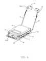
- FIG. 1is a perspective view of an electrical connector assembly of the invention according to the presently preferred embodiment
- FIG. 2is another perspective view of the electrical connector assembly of FIG. 1 ;
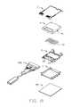
- FIG. 3is an exploded perspective view of the electrical connector assembly of FIG. 1 ;
- FIG. 4is another exploded perspective view of the electrical connector assembly of FIG. 1 ;
- FIG. 5is a partially assembled perspective view of the electrical connector assembly of FIG. 4 ;
- FIG. 6is a further assembled perspective view of the electrical connector assembly of FIG. 5 ;
- FIG. 7is another perspective view of the electrical connector assembly of FIG. 6 ;
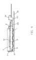
- FIG. 8is a side view of the electrical connector assembly of FIG. 1 to show the retention lever is locked in position;
- FIG. 9is another side view of the electrical connector assembly of FIG. 1 to show the retention lever is downwardly deflected excessively;
- FIG. 10is a further exploded perspective view of the electrical connector assembly of FIG. 3 .
- an electrical connector assemblyfor connection between an optical device and a printed circuit board 100 , includes a frame 1 , a housing 2 received within the frame 1 , a retention lever 3 pivotally mounted upon the frame 2 and an optoelectronic module 4 received within the housing and retained by the retention lever 3 .
- An optical jumper module 200is located in a front portion of the housing 2 and optically coupled to the optoelectronic module 4 ,
- the retention lever 3includes a rear pivotal section 31 mounted to the frame 2 , a middle pressing section 32 for pressing downward the optoelectronic module 4 , a front handling section 33 for operating the retention lever 3 , and an abutment block 34 formed on the handling section 33 .
- the abutment block 34includes a pressing region 341 and a protrusion 342 downwardly projecting toward the printed circuit board 100 and functioning as a protection stopper.
- the abutment block 34is located higher than the optical jumper module 200 in the vertical direction and is rearwardly spaced from the optical jumper module 200 in the front-to-back direction. Therefore, downward deflection of the abutment block 34 will not improperly touch or even damage the corresponding optical jumper module 200 .
- the fibers (not labeled) of the optical jumper module 200can be received in a space 343 under the abutment block 34 without damage.
- the pressing region 341is formed with ribs 344 to stabilize the fingers thereupon during operation.
- the handling sections 33are located in front of the housing 2 and spaced from each other in the transverse direction with a distance therebetween. Understandably, the separation of the handling sections 33 with the associated abutment blocks 34 in the transverse direction is to allow each pressing section 32 to be outwardly/laterally deflectable for loading/uploading the optoelectronic module 4 with regard to the housing 2 .
- the pressing section 32is downwardly pressed by the corresponding hook 11 of the frame 1 and simultaneously downwardly presses the ear 41 of the optoelectronic module 4 so as to retain the optoelectronic module 4 in the housing 2 in position.
- the pivotal section 31includes a fixing part 311 extending along the pivotal axis, and a resisting part 312 offset from the fixing part 311 with a parallel distance.
- the frame 1includes a pair of restriction section 12 so as to have the fixing part 311 is pivotally mounted thereto. Notably, when the retention lever 3 is moved to the outermost open position, the resisting part 312 abuts against the printed circuit board 100 .
- the handling section 33 with the corresponding abutment block 34is downwardly moved by the finger so as to have the pressing section 32 is downwardly deflected and disengaged from the hook 11 and further outwardly/laterally slightly deflected and successively upwardly moved with rotation more than ninety degrees until the resisting part 312 abuts against the printed circuit board as shown in FIG. 7 .
- the ear 41is no longer pressed downwardly by the pressing section 32 so as to allow the optoelectronic module 4 to be removed from the housing 2 .
- the optical jumper module 200which is originally downwardly loaded into and restrictively received within the front portion of the housing 2 , is also allowed to be upwardly released from the housing 2 , as what is understandably shown in the corresponding figures of the aforementioned U.S. Pat. No. 9,730,351.
- the step structure 24 at the front end of the housing 2restricts the optical jumper module 200 from forwardly moving after the optical jumper module 200 is downwardly loaded into the front portion of the housing 2 .
- the optical jumper 200is also downwardly pressed by the optoelectronic module 4 after assembled. In other words, the optoelectronic module 4 should be upwardly removed from the housing 2 before the optical jumper module 200 is upwardly removed from the housing 2 .
- the housing 2further includes a rear wall 21 to allow the resisting part 312 to abut thereagainst when no optoelectronic module 4 is received within the housing 2 and no ear 41 is available for the pressing section 32 to press against. It is also noted that the detailed structure of the housing 2 including the complementary connector therein is not shown, which the connector 42 of the optoelectronic module 4 is mated with.
- the spirit of the inventionis to provide the downward protrusion 342 of the abutment block 34 , which is adapted to abut against the printed circuit board 100 when the retention lever 3 is about to be excessively deflected and the handling section 33 is about to be excessively moved, so as to prevent excessively forces from being applied upon the optoelectronic module 4 due to engagement between the pressing section 32 and the ear 41 , thus removing a risk of damaging the optoelectronic module 4 .
- the downward protrusion 342leaves the sufficient space thereabouts not to interfere with the optical jumper module 200 so as to remove a risk of damaging the optical jumper module 200 .
- the pivotal section of the retention levermay be mounted to the housing rather than the frame, and the hook for keeping the retention lever in the closed position may be formed upon the housing rather than frame, the step structure for restricting forward movement of the optical jumper module may be formed on the frame rather than the housing.
Landscapes
- Physics & Mathematics (AREA)
- General Physics & Mathematics (AREA)
- Optics & Photonics (AREA)
- Optical Couplings Of Light Guides (AREA)
Abstract
Description
Claims (20)
Applications Claiming Priority (3)
| Application Number | Priority Date | Filing Date | Title |
|---|---|---|---|
| CN201610675084.8 | 2016-08-17 | ||
| CN201610675084 | 2016-08-17 | ||
| CN201610675084.8ACN107768910B (en) | 2016-08-17 | 2016-08-17 | Electric connector combination |
Publications (2)
| Publication Number | Publication Date |
|---|---|
| US20180052292A1 US20180052292A1 (en) | 2018-02-22 |
| US10386591B2true US10386591B2 (en) | 2019-08-20 |
Family
ID=61191470
Family Applications (1)
| Application Number | Title | Priority Date | Filing Date |
|---|---|---|---|
| US15/680,165Expired - Fee RelatedUS10386591B2 (en) | 2016-08-17 | 2017-08-17 | Electrical connector for use with optoelectronic module |
Country Status (3)
| Country | Link |
|---|---|
| US (1) | US10386591B2 (en) |
| CN (1) | CN107768910B (en) |
| TW (1) | TWI742136B (en) |
Families Citing this family (1)
| Publication number | Priority date | Publication date | Assignee | Title |
|---|---|---|---|---|
| TWI874083B (en)* | 2023-12-29 | 2025-02-21 | 利鴻科技股份有限公司 | Electrical connector structure |
Citations (9)
| Publication number | Priority date | Publication date | Assignee | Title |
|---|---|---|---|---|
| US5011426A (en)* | 1990-02-02 | 1991-04-30 | Molex Incorporated | Electrical connector assembly for vehicular suspension system component |
| US20040081406A1 (en)* | 2001-03-01 | 2004-04-29 | Thomas Grob | Fiber-optical connector system |
| US20060029336A1 (en)* | 2004-08-06 | 2006-02-09 | Gunther Peter U | Opto-electrical module for optical signals from at least two optical data channels for arranging on a main circuit board of a component assembly and opto-electrical component assembly |
| TWM331235U (en) | 2007-08-24 | 2008-04-21 | Hon Hai Prec Ind Co Ltd | Electrical connector |
| TWM375313U (en) | 2009-08-04 | 2010-03-01 | Hon Hai Prec Ind Co Ltd | Electrical connector |
| US20130294732A1 (en)* | 2012-03-05 | 2013-11-07 | Nanoprecision Products, Inc. | Hermetic optical fiber alignment assembly having integrated optical element |
| TWM491975U (en) | 2014-05-28 | 2014-12-11 | Hon Hai Prec Ind Co Ltd | Electrical connector assembly |
| US20160006170A1 (en)* | 2014-07-01 | 2016-01-07 | Hon Hai Precision Industry Co., Ltd. | Electrical connector assembly with jumper element assembled thereon |
| US9730351B2 (en) | 2014-07-01 | 2017-08-08 | Foxconn Interconnect Technology Limited | Electrical connector assembly with holding member |
Family Cites Families (3)
| Publication number | Priority date | Publication date | Assignee | Title |
|---|---|---|---|---|
| US20080160814A1 (en)* | 2006-12-28 | 2008-07-03 | Hon Hai Precision Ind. Co., Ltd. | Land grid array connector assembly with pick up cap |
| TW201445207A (en)* | 2013-05-30 | 2014-12-01 | Hon Hai Prec Ind Co Ltd | Retention module |
| CN203983618U (en)* | 2014-05-29 | 2014-12-03 | 富士康(昆山)电脑接插件有限公司 | Electric coupler component |
- 2016
- 2016-08-17CNCN201610675084.8Apatent/CN107768910B/enactiveActive
- 2017
- 2017-08-16TWTW106127705Apatent/TWI742136B/ennot_activeIP Right Cessation
- 2017-08-17USUS15/680,165patent/US10386591B2/ennot_activeExpired - Fee Related
Patent Citations (10)
| Publication number | Priority date | Publication date | Assignee | Title |
|---|---|---|---|---|
| US5011426A (en)* | 1990-02-02 | 1991-04-30 | Molex Incorporated | Electrical connector assembly for vehicular suspension system component |
| US20040081406A1 (en)* | 2001-03-01 | 2004-04-29 | Thomas Grob | Fiber-optical connector system |
| US20060029336A1 (en)* | 2004-08-06 | 2006-02-09 | Gunther Peter U | Opto-electrical module for optical signals from at least two optical data channels for arranging on a main circuit board of a component assembly and opto-electrical component assembly |
| TWM331235U (en) | 2007-08-24 | 2008-04-21 | Hon Hai Prec Ind Co Ltd | Electrical connector |
| TWM375313U (en) | 2009-08-04 | 2010-03-01 | Hon Hai Prec Ind Co Ltd | Electrical connector |
| US20130294732A1 (en)* | 2012-03-05 | 2013-11-07 | Nanoprecision Products, Inc. | Hermetic optical fiber alignment assembly having integrated optical element |
| TWM491975U (en) | 2014-05-28 | 2014-12-11 | Hon Hai Prec Ind Co Ltd | Electrical connector assembly |
| US20150349442A1 (en)* | 2014-05-28 | 2015-12-03 | Foxconn Interconnect Technology Limited | Electrical connector assembly with locking member |
| US20160006170A1 (en)* | 2014-07-01 | 2016-01-07 | Hon Hai Precision Industry Co., Ltd. | Electrical connector assembly with jumper element assembled thereon |
| US9730351B2 (en) | 2014-07-01 | 2017-08-08 | Foxconn Interconnect Technology Limited | Electrical connector assembly with holding member |
Also Published As
| Publication number | Publication date |
|---|---|
| CN107768910A (en) | 2018-03-06 |
| TW201810827A (en) | 2018-03-16 |
| CN107768910B (en) | 2020-09-25 |
| TWI742136B (en) | 2021-10-11 |
| US20180052292A1 (en) | 2018-02-22 |
Similar Documents
| Publication | Publication Date | Title |
|---|---|---|
| KR970002442B1 (en) | Ic-pack connector apparatus | |
| US10921166B2 (en) | Sensor bracket | |
| US8882528B2 (en) | Connector | |
| US9379487B2 (en) | Card connector | |
| US20100265679A1 (en) | Locking assembly for locking an electronics card to a rack | |
| US9893458B2 (en) | Dust-proof cover and electrical connector assembly using the same | |
| US8157601B2 (en) | Contact for electrical connector | |
| US7455555B1 (en) | All-in-one card connector preventing card from erroneous insertion therein and allowing insertion of card once only | |
| CN113163904B (en) | Plug for buckle and buckle | |
| US9817449B2 (en) | Housing having a carrier device | |
| JP6787943B2 (en) | Connection structure and connector | |
| US20090294618A1 (en) | Clamp-type hard disk mount | |
| US10386591B2 (en) | Electrical connector for use with optoelectronic module | |
| US9601868B2 (en) | Module latch actuator | |
| CN107925181A (en) | Connector | |
| JP2015043299A5 (en) | ||
| US8303322B1 (en) | Card connector anti-misinserting a micro SD card | |
| JP6587595B2 (en) | Lever type connector | |
| US9337573B2 (en) | Electrical connector assembly with jumper element assembled thereon | |
| CN104979658B (en) | Connector | |
| US9629277B2 (en) | Fastener and server using the same | |
| WO2013111763A1 (en) | Connector | |
| US11382234B2 (en) | Connection device | |
| US10601177B1 (en) | Electrical connector lock with reverse stop | |
| JP2002313486A (en) | Split connector |
Legal Events
| Date | Code | Title | Description |
|---|---|---|---|
| AS | Assignment | Owner name:FOXCONN INTERCONNECT TECHNOLOGY LIMITED, CAYMAN IS Free format text:ASSIGNMENT OF ASSIGNORS INTEREST;ASSIGNOR:HSU, SHUO-HSIU;REEL/FRAME:043326/0626 Effective date:20170810 | |
| STPP | Information on status: patent application and granting procedure in general | Free format text:RESPONSE TO NON-FINAL OFFICE ACTION ENTERED AND FORWARDED TO EXAMINER | |
| STPP | Information on status: patent application and granting procedure in general | Free format text:NOTICE OF ALLOWANCE MAILED -- APPLICATION RECEIVED IN OFFICE OF PUBLICATIONS | |
| STPP | Information on status: patent application and granting procedure in general | Free format text:PUBLICATIONS -- ISSUE FEE PAYMENT VERIFIED | |
| STCF | Information on status: patent grant | Free format text:PATENTED CASE | |
| FEPP | Fee payment procedure | Free format text:MAINTENANCE FEE REMINDER MAILED (ORIGINAL EVENT CODE: REM.); ENTITY STATUS OF PATENT OWNER: LARGE ENTITY | |
| LAPS | Lapse for failure to pay maintenance fees | Free format text:PATENT EXPIRED FOR FAILURE TO PAY MAINTENANCE FEES (ORIGINAL EVENT CODE: EXP.); ENTITY STATUS OF PATENT OWNER: LARGE ENTITY | |
| STCH | Information on status: patent discontinuation | Free format text:PATENT EXPIRED DUE TO NONPAYMENT OF MAINTENANCE FEES UNDER 37 CFR 1.362 | |
| FP | Lapsed due to failure to pay maintenance fee | Effective date:20230820 |