US10386467B2 - Ladar pulse deconfliction apparatus - Google Patents
Ladar pulse deconfliction apparatusDownload PDFInfo
- Publication number
- US10386467B2 US10386467B2US15/896,233US201815896233AUS10386467B2US 10386467 B2US10386467 B2US 10386467B2US 201815896233 AUS201815896233 AUS 201815896233AUS 10386467 B2US10386467 B2US 10386467B2
- Authority
- US
- United States
- Prior art keywords
- pulse
- delay
- circuit
- delays
- pulses
- Prior art date
- Legal status (The legal status is an assumption and is not a legal conclusion. Google has not performed a legal analysis and makes no representation as to the accuracy of the status listed.)
- Active
Links
- 230000001934delayEffects0.000claimsabstractdescription79
- 238000000034methodMethods0.000claimsabstractdescription44
- 230000003111delayed effectEffects0.000claimsdescription42
- 230000008569processEffects0.000claimsdescription22
- 230000001413cellular effectEffects0.000claimsdescription5
- 238000007619statistical methodMethods0.000claims2
- 230000003287optical effectEffects0.000abstractdescription43
- 238000004891communicationMethods0.000abstractdescription41
- 230000002452interceptive effectEffects0.000abstractdescription21
- 238000013461designMethods0.000abstractdescription3
- 238000001514detection methodMethods0.000description26
- 238000012545processingMethods0.000description26
- 238000001208nuclear magnetic resonance pulse sequenceMethods0.000description9
- 238000005516engineering processMethods0.000description7
- 238000013459approachMethods0.000description6
- 230000008901benefitEffects0.000description5
- 230000007613environmental effectEffects0.000description5
- 238000002955isolationMethods0.000description5
- 239000000523sampleSubstances0.000description5
- 238000012360testing methodMethods0.000description5
- 230000003044adaptive effectEffects0.000description4
- 230000005540biological transmissionEffects0.000description4
- 230000008859changeEffects0.000description4
- 238000010304firingMethods0.000description4
- 238000012544monitoring processMethods0.000description4
- 230000000875corresponding effectEffects0.000description3
- 230000006870functionEffects0.000description3
- 238000013507mappingMethods0.000description3
- 238000007792additionMethods0.000description2
- 230000003190augmentative effectEffects0.000description2
- 238000007906compressionMethods0.000description2
- 230000006835compressionEffects0.000description2
- 230000001419dependent effectEffects0.000description2
- 238000002592echocardiographyMethods0.000description2
- 230000000694effectsEffects0.000description2
- 238000001914filtrationMethods0.000description2
- 230000001976improved effectEffects0.000description2
- 230000000116mitigating effectEffects0.000description2
- 238000012986modificationMethods0.000description2
- 230000004048modificationEffects0.000description2
- 230000010287polarizationEffects0.000description2
- 210000001747pupilAnatomy0.000description2
- 238000012216screeningMethods0.000description2
- 230000007480spreadingEffects0.000description2
- 230000001960triggered effectEffects0.000description2
- 241001532039CamassiaSpecies0.000description1
- 241000282412HomoSpecies0.000description1
- 238000004458analytical methodMethods0.000description1
- 230000003416augmentationEffects0.000description1
- 230000009286beneficial effectEffects0.000description1
- 230000033228biological regulationEffects0.000description1
- 230000015572biosynthetic processEffects0.000description1
- 238000004364calculation methodMethods0.000description1
- 230000010267cellular communicationEffects0.000description1
- 238000012512characterization methodMethods0.000description1
- 230000002596correlated effectEffects0.000description1
- 230000004069differentiationEffects0.000description1
- 238000009792diffusion processMethods0.000description1
- 230000009977dual effectEffects0.000description1
- 230000002708enhancing effectEffects0.000description1
- 210000000887faceAnatomy0.000description1
- 238000009472formulationMethods0.000description1
- 230000004927fusionEffects0.000description1
- 238000010191image analysisMethods0.000description1
- 230000000977initiatory effectEffects0.000description1
- 238000007689inspectionMethods0.000description1
- 230000004807localizationEffects0.000description1
- 238000012423maintenanceMethods0.000description1
- 238000007726management methodMethods0.000description1
- 239000011159matrix materialSubstances0.000description1
- 238000005259measurementMethods0.000description1
- 239000000203mixtureSubstances0.000description1
- 230000008450motivationEffects0.000description1
- 230000036961partial effectEffects0.000description1
- 238000002360preparation methodMethods0.000description1
- 238000004321preservationMethods0.000description1
- 230000002829reductive effectEffects0.000description1
- 230000000717retained effectEffects0.000description1
- 238000012552reviewMethods0.000description1
- 230000003068static effectEffects0.000description1
- 230000008685targetingEffects0.000description1
- 230000002123temporal effectEffects0.000description1
- 238000012546transferMethods0.000description1
- 238000002604ultrasonographyMethods0.000description1
- 238000011144upstream manufacturingMethods0.000description1
- 238000001429visible spectrumMethods0.000description1
- XLYOFNOQVPJJNP-UHFFFAOYSA-NwaterSubstancesOXLYOFNOQVPJJNP-UHFFFAOYSA-N0.000description1
Images


Classifications
- G—PHYSICS
- G01—MEASURING; TESTING
- G01S—RADIO DIRECTION-FINDING; RADIO NAVIGATION; DETERMINING DISTANCE OR VELOCITY BY USE OF RADIO WAVES; LOCATING OR PRESENCE-DETECTING BY USE OF THE REFLECTION OR RERADIATION OF RADIO WAVES; ANALOGOUS ARRANGEMENTS USING OTHER WAVES
- G01S7/00—Details of systems according to groups G01S13/00, G01S15/00, G01S17/00
- G01S7/48—Details of systems according to groups G01S13/00, G01S15/00, G01S17/00 of systems according to group G01S17/00
- G01S7/483—Details of pulse systems
- G01S7/486—Receivers
- G01S7/4861—Circuits for detection, sampling, integration or read-out
- G01S17/023—
- G—PHYSICS
- G01—MEASURING; TESTING
- G01S—RADIO DIRECTION-FINDING; RADIO NAVIGATION; DETERMINING DISTANCE OR VELOCITY BY USE OF RADIO WAVES; LOCATING OR PRESENCE-DETECTING BY USE OF THE REFLECTION OR RERADIATION OF RADIO WAVES; ANALOGOUS ARRANGEMENTS USING OTHER WAVES
- G01S17/00—Systems using the reflection or reradiation of electromagnetic waves other than radio waves, e.g. lidar systems
- G01S17/02—Systems using the reflection of electromagnetic waves other than radio waves
- G01S17/06—Systems determining position data of a target
- G01S17/08—Systems determining position data of a target for measuring distance only
- G01S17/10—Systems determining position data of a target for measuring distance only using transmission of interrupted, pulse-modulated waves
- G—PHYSICS
- G01—MEASURING; TESTING
- G01S—RADIO DIRECTION-FINDING; RADIO NAVIGATION; DETERMINING DISTANCE OR VELOCITY BY USE OF RADIO WAVES; LOCATING OR PRESENCE-DETECTING BY USE OF THE REFLECTION OR RERADIATION OF RADIO WAVES; ANALOGOUS ARRANGEMENTS USING OTHER WAVES
- G01S17/00—Systems using the reflection or reradiation of electromagnetic waves other than radio waves, e.g. lidar systems
- G01S17/66—Tracking systems using electromagnetic waves other than radio waves
- G—PHYSICS
- G01—MEASURING; TESTING
- G01S—RADIO DIRECTION-FINDING; RADIO NAVIGATION; DETERMINING DISTANCE OR VELOCITY BY USE OF RADIO WAVES; LOCATING OR PRESENCE-DETECTING BY USE OF THE REFLECTION OR RERADIATION OF RADIO WAVES; ANALOGOUS ARRANGEMENTS USING OTHER WAVES
- G01S17/00—Systems using the reflection or reradiation of electromagnetic waves other than radio waves, e.g. lidar systems
- G01S17/86—Combinations of lidar systems with systems other than lidar, radar or sonar, e.g. with direction finders
- G—PHYSICS
- G01—MEASURING; TESTING
- G01S—RADIO DIRECTION-FINDING; RADIO NAVIGATION; DETERMINING DISTANCE OR VELOCITY BY USE OF RADIO WAVES; LOCATING OR PRESENCE-DETECTING BY USE OF THE REFLECTION OR RERADIATION OF RADIO WAVES; ANALOGOUS ARRANGEMENTS USING OTHER WAVES
- G01S17/00—Systems using the reflection or reradiation of electromagnetic waves other than radio waves, e.g. lidar systems
- G01S17/88—Lidar systems specially adapted for specific applications
- G01S17/93—Lidar systems specially adapted for specific applications for anti-collision purposes
- G01S17/931—Lidar systems specially adapted for specific applications for anti-collision purposes of land vehicles
- G01S17/936—
- G—PHYSICS
- G01—MEASURING; TESTING
- G01S—RADIO DIRECTION-FINDING; RADIO NAVIGATION; DETERMINING DISTANCE OR VELOCITY BY USE OF RADIO WAVES; LOCATING OR PRESENCE-DETECTING BY USE OF THE REFLECTION OR RERADIATION OF RADIO WAVES; ANALOGOUS ARRANGEMENTS USING OTHER WAVES
- G01S7/00—Details of systems according to groups G01S13/00, G01S15/00, G01S17/00
- G01S7/003—Transmission of data between radar, sonar or lidar systems and remote stations
- G01S7/006—Transmission of data between radar, sonar or lidar systems and remote stations using shared front-end circuitry, e.g. antennas
- G—PHYSICS
- G01—MEASURING; TESTING
- G01S—RADIO DIRECTION-FINDING; RADIO NAVIGATION; DETERMINING DISTANCE OR VELOCITY BY USE OF RADIO WAVES; LOCATING OR PRESENCE-DETECTING BY USE OF THE REFLECTION OR RERADIATION OF RADIO WAVES; ANALOGOUS ARRANGEMENTS USING OTHER WAVES
- G01S7/00—Details of systems according to groups G01S13/00, G01S15/00, G01S17/00
- G01S7/48—Details of systems according to groups G01S13/00, G01S15/00, G01S17/00 of systems according to group G01S17/00
- G01S7/481—Constructional features, e.g. arrangements of optical elements
- G01S7/4814—Constructional features, e.g. arrangements of optical elements of transmitters alone
- G—PHYSICS
- G01—MEASURING; TESTING
- G01S—RADIO DIRECTION-FINDING; RADIO NAVIGATION; DETERMINING DISTANCE OR VELOCITY BY USE OF RADIO WAVES; LOCATING OR PRESENCE-DETECTING BY USE OF THE REFLECTION OR RERADIATION OF RADIO WAVES; ANALOGOUS ARRANGEMENTS USING OTHER WAVES
- G01S7/00—Details of systems according to groups G01S13/00, G01S15/00, G01S17/00
- G01S7/48—Details of systems according to groups G01S13/00, G01S15/00, G01S17/00 of systems according to group G01S17/00
- G01S7/481—Constructional features, e.g. arrangements of optical elements
- G01S7/4816—Constructional features, e.g. arrangements of optical elements of receivers alone
- G—PHYSICS
- G01—MEASURING; TESTING
- G01S—RADIO DIRECTION-FINDING; RADIO NAVIGATION; DETERMINING DISTANCE OR VELOCITY BY USE OF RADIO WAVES; LOCATING OR PRESENCE-DETECTING BY USE OF THE REFLECTION OR RERADIATION OF RADIO WAVES; ANALOGOUS ARRANGEMENTS USING OTHER WAVES
- G01S7/00—Details of systems according to groups G01S13/00, G01S15/00, G01S17/00
- G01S7/48—Details of systems according to groups G01S13/00, G01S15/00, G01S17/00 of systems according to group G01S17/00
- G01S7/483—Details of pulse systems
- G01S7/484—Transmitters
- G—PHYSICS
- G01—MEASURING; TESTING
- G01S—RADIO DIRECTION-FINDING; RADIO NAVIGATION; DETERMINING DISTANCE OR VELOCITY BY USE OF RADIO WAVES; LOCATING OR PRESENCE-DETECTING BY USE OF THE REFLECTION OR RERADIATION OF RADIO WAVES; ANALOGOUS ARRANGEMENTS USING OTHER WAVES
- G01S7/00—Details of systems according to groups G01S13/00, G01S15/00, G01S17/00
- G01S7/48—Details of systems according to groups G01S13/00, G01S15/00, G01S17/00 of systems according to group G01S17/00
- G01S7/483—Details of pulse systems
- G01S7/486—Receivers
- G01S7/4865—Time delay measurement, e.g. time-of-flight measurement, time of arrival measurement or determining the exact position of a peak
- G—PHYSICS
- G01—MEASURING; TESTING
- G01S—RADIO DIRECTION-FINDING; RADIO NAVIGATION; DETERMINING DISTANCE OR VELOCITY BY USE OF RADIO WAVES; LOCATING OR PRESENCE-DETECTING BY USE OF THE REFLECTION OR RERADIATION OF RADIO WAVES; ANALOGOUS ARRANGEMENTS USING OTHER WAVES
- G01S7/00—Details of systems according to groups G01S13/00, G01S15/00, G01S17/00
- G01S7/48—Details of systems according to groups G01S13/00, G01S15/00, G01S17/00 of systems according to group G01S17/00
- G01S7/483—Details of pulse systems
- G01S7/486—Receivers
- G01S7/487—Extracting wanted echo signals, e.g. pulse detection
- G01S7/4873—Extracting wanted echo signals, e.g. pulse detection by deriving and controlling a threshold value
- G—PHYSICS
- G01—MEASURING; TESTING
- G01S—RADIO DIRECTION-FINDING; RADIO NAVIGATION; DETERMINING DISTANCE OR VELOCITY BY USE OF RADIO WAVES; LOCATING OR PRESENCE-DETECTING BY USE OF THE REFLECTION OR RERADIATION OF RADIO WAVES; ANALOGOUS ARRANGEMENTS USING OTHER WAVES
- G01S7/00—Details of systems according to groups G01S13/00, G01S15/00, G01S17/00
- G01S7/48—Details of systems according to groups G01S13/00, G01S15/00, G01S17/00 of systems according to group G01S17/00
- G01S7/483—Details of pulse systems
- G01S7/486—Receivers
- G01S7/487—Extracting wanted echo signals, e.g. pulse detection
- G01S7/4876—Extracting wanted echo signals, e.g. pulse detection by removing unwanted signals
- H—ELECTRICITY
- H04—ELECTRIC COMMUNICATION TECHNIQUE
- H04B—TRANSMISSION
- H04B10/00—Transmission systems employing electromagnetic waves other than radio-waves, e.g. infrared, visible or ultraviolet light, or employing corpuscular radiation, e.g. quantum communication
- H04B10/11—Arrangements specific to free-space transmission, i.e. transmission through air or vacuum
- H04B10/112—Line-of-sight transmission over an extended range
- H04B10/1123—Bidirectional transmission
- G—PHYSICS
- G01—MEASURING; TESTING
- G01S—RADIO DIRECTION-FINDING; RADIO NAVIGATION; DETERMINING DISTANCE OR VELOCITY BY USE OF RADIO WAVES; LOCATING OR PRESENCE-DETECTING BY USE OF THE REFLECTION OR RERADIATION OF RADIO WAVES; ANALOGOUS ARRANGEMENTS USING OTHER WAVES
- G01S17/00—Systems using the reflection or reradiation of electromagnetic waves other than radio waves, e.g. lidar systems
- G01S17/88—Lidar systems specially adapted for specific applications
- G01S17/89—Lidar systems specially adapted for specific applications for mapping or imaging
- G—PHYSICS
- G01—MEASURING; TESTING
- G01S—RADIO DIRECTION-FINDING; RADIO NAVIGATION; DETERMINING DISTANCE OR VELOCITY BY USE OF RADIO WAVES; LOCATING OR PRESENCE-DETECTING BY USE OF THE REFLECTION OR RERADIATION OF RADIO WAVES; ANALOGOUS ARRANGEMENTS USING OTHER WAVES
- G01S13/00—Systems using the reflection or reradiation of radio waves, e.g. radar systems; Analogous systems using reflection or reradiation of waves whose nature or wavelength is irrelevant or unspecified
- G01S13/88—Radar or analogous systems specially adapted for specific applications
- G01S13/93—Radar or analogous systems specially adapted for specific applications for anti-collision purposes
- G01S13/931—Radar or analogous systems specially adapted for specific applications for anti-collision purposes of land vehicles
- G01S2013/9316—Radar or analogous systems specially adapted for specific applications for anti-collision purposes of land vehicles combined with communication equipment with other vehicles or with base stations
- G01S2013/936—
Definitions
- autonomous platform visione.g., autonomous vehicles for air, land (including underground), water (including underwater), and space, such as autonomous land-based vehicles, autonomous aerial vehicles, etc.
- surveillancee.g., border security, aerial drone monitoring, etc.
- mappinge.g., mapping of sub-surface tunnels, mapping via aerial drones, etc.
- target recognition applicationse.g., remote sensing, safety alerting (e.g., for drivers), and the like.
- ladarrefers to and encompasses any of laser radar, laser detection and ranging, and light detection and ranging (“lidar”).
- Ladaris a technology widely used in connection with computer vision.
- a transmitter that includes a laser sourcetransmits a laser output such as a ladar pulse into a nearby environment.
- a ladar receiverwill receive a reflection of this laser output from an object in the nearby environment, and the ladar receiver will process the received reflection to determine a distance to such an object (range information). Based on this range information, a clearer understanding of the environment's geometry can be obtained by a host processor wishing to compute things such as path planning in obstacle avoidance scenarios, way point determination, etc.
- ladar receiverswill detect noisy light signals, and there is a need for technology that is capable of distinguishing between “own” pulse reflections and “interfering” pulses/pulse reflections within this noisy signal while operating in real-time in the field.
- the ladar transmitterscan be designed to encode their own ladar pulses via a delay between successive ladar pulses.
- different ladar transmitterscan employ different delays between successive ladar pulses to allow ladar receivers to distinguish between “own” ladar pulses and “interfering” ladar pulses.
- these delaysare fairly short time intervals and the number of pulses in the pulse sequence is kept low so as to keep the square root loss in effective energy low.
- the encodingcan be referred to as a sparse burst code.
- the pulse sequencecan be a pulse pair (doublet) such that a single delay between pulses is used to distinguish “own” pulses from “interfering” pulses.
- the pulse sequencecan be three pulses (triplet) such that two delays are used for encoding.
- n pulsesn-tuple
- n ⁇ 1 delaysthere would be n ⁇ 1 delays that can be used for encoding.
- Another benefit of the sparse burst codeis that the number of samples needed to represent the pulses can be low, which contributes to computational efficiency and low latency processing.
- the ladar receiver systemcan decode the received delay-encoded pulses without the need for cooperation or communication with outside systems which is advantageous in situations where such communication may not always be possible or available. Further still, the pulse decoding process for the delay-encoded pulses can be efficiently implemented by the receiver system such that the ladar system can still operate at desired speeds.
- a delay sum circuitcan be employed to detect the presence of “own” pulse reflections within a received ladar signal.
- the delay sum circuitcan perform coarse-grained pulse detection.
- the delay sum circuitcan be augmented with additional comparators to perform fine-grained pulse detection.
- the inventorsalso disclose that the pulse deconfliction techniques described herein can also be used to detect and track the existence of other ladar systems in an environment that employ different delay codes between ladar pulses.
- laser dosage tracking as described hereincan be employed to reduce the risks of overly exposing humans and cameras to excessive laser light.
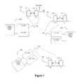
- FIG. 1discloses an example environment where multiple ladar systems may pose interference threats to each other.
- FIG. 2Adepicts an example signal processing circuit that can be used for doublet pulse deconfliction to decode an incoming signal and detect the presence of any “own” pulse reflections using sparse summation.
- FIG. 2Bshows another example embodiment of a signal processing circuit that can be used for doublet pulse deconfliction using sparse summation with data adaptive thresholding.
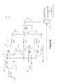
- FIG. 2Cshows an example embodiment of a signal processing circuit that can be used for triplet pulse deconfliction using sparse summation.
- FIG. 2Dshows an example process flow for enhanced deconfliction using a triple comparator, which can be applied to delay code(s) of any length.
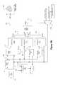
- FIG. 3Adepicts an example signal processing circuit that can be used for doublet pulse deconfliction to decode an incoming signal and detect the presence of any “own” pulse reflections using the triple comparator scheme in 2D for fine-grained detection.
- FIG. 3Bshows another example embodiment of a signal processing circuit that can be used for fine-grained doublet pulse deconfliction. This embodiment expands on FIG. 3A by adding a data adaptive threshold. Because of the shape of the decision region we call this a funnel filter.
- FIG. 3Cshows formulas that can be used to measure various detection metrics.
- FIG. 4shows a plot that measured filter performance in terms of detection probability versus SNR for doublets and triplets.
- FIG. 5shows an example process flow for generating delay codes using hashing techniques.
- FIG. 7shows an example process flow for using position detection to influence delay code selection.
- FIG. 8shows an example process flow for using vehicle-to-vehicle communications to collaboratively define delay codes.
- FIG. 9shows an example process flow for using billboard techniques to define delay codes.
- FIG. 10shows an example pulse deconfliction data flow for a case of 8 bits, 800 MHz ADC, with a triple pulse code, with maximum code delay length of 80 nsec.
- FIG. 12shows an example embodiment of a ladar receiver augmented to also receive other optical information.
- FIG. 13shows an example embodiment of an optical transceiver that can serve as a free space, point-to-point optical data communication system.
- FIGS. 14A and 14Bshow example embodiments of a laser heat map control loop.
- FIG. 1depicts an example environment where there are multiple ladar systems 100 (e.g., 100 1 , 100 2 , . . . 100 n ) that transmit ladar pulses.
- Each ladar system 100comprises a ladar transmitter 102 , a ladar receiver 104 , and a control system 106 .
- Each ladar transmitter 102is configured to generate and transmit ladar pulses into the environment.
- Each ladar receiver 104is configured to receive and detect a light signal that may include ladar pulse reflections. As noted above, this received signal may also include noise such as interfering pulses/pulse reflections from other ladar systems.
- Each control system 106can be configured to control how its corresponding ladar transmitter 102 and ladar receiver 104 operate.
- Examples of suitable ladar systems 100are disclosed and described in greater detail in U.S. patent application Ser. No. 62/038,065, filed Aug. 15, 2014; and U.S. Pat. App. Pubs. 2016/0047895, 2016/0047896, 2016/0047897, 2016/0047898, 2016/0047899, 2016/0047903, 2016/0047900, 2017/0242102, 2017/0242103, 2017/0242104, 2017/0242105, 2017/0242106, 2017/0242107, and 2017/0242109, the entire disclosures of which are incorporated herein by reference.
- the ladar system 100may employ a ladar transmitter 102 (as described in the above-referenced and incorporated patent applications) that includes scanning mirrors and uses a range point down selection algorithm to support pre-scan compression (which can be referred herein to as “compressive sensing”).
- a ladar transmitter 102as described in the above-referenced and incorporated patent applications
- Such an embodimentmay also include an environmental sensing system 120 that provides environmental scene data to the ladar transmitter to support the range point down selection.
- pre-scan compressionsuch a ladar transmitter can better manage bandwidth through intelligent range point target selection.
- the detection and image quality for a ladar systemvaries as the square root of the number of pulses used per point cloud, this means that reducing the required number of communication pulses via the compressive sensing enhances the signal to noise ratio (SNR), enabling robust pulse collision avoidance without greatly reducing detection range or position accuracy. Accordingly, the pulse deconfliction techniques described herein are particularly beneficial when combined with a ladar transmitter that employs compressive sensing. While these referenced and incorporated patent applications describe example embodiments for ladar systems 100 , it should nevertheless be understood that practitioners may choose to implement the ladar systems 100 differently than as disclosed in these referenced and incorporated patent applications.
- the ladar systemscan distinguish between each other's pulses based on the delays that are present between successive ladar pulses transmitted by each ladar transmitter 102 .
- the ladar transmitter 102 for ladar system 100 1can generate a pulse sequence 110 1 with a delay of L between pulses 112 1 and 114 1 .
- the ladar transmitter 102 for ladar system 100 2can generate a pulse sequence 110 2 with a delay of M between pulses 112 2 and 114 2 , and so on (including ladar transmitter 102 for ladar system 100 n generating a pulse sequence 110 n with a delay of N between pulses 112 n and 114 n ).
- L, M, and Nare all different values to support pulse differentiation by the ladar systems 100 .
- FIG. 1shows that the various pulse sequences 110 are doublets, it should be understood that longer pulses sequences could be used if desired by a practitioner (e.g., a n-tuple pulse sequence where each pulse sequence includes n ⁇ 1 delays).
- FIG. 2Adepicts an example signal processing circuit 220 that can be used on the ladar system 100 's receive side to decode an incoming signal to detect the presence of any “own” pulse reflections.
- the “own” ladar pulse transmitted by the subject ladar system 100can be expected to largely retain the delay L between its pulses when it strikes an object in the environment and is reflected back to the receiver 104 .
- the signal sensed by receiver 104will also include noise such as interfering ladar pulses and interfering pulse reflections.
- FIG. 1depicts an example signal processing circuit 220 that can be used on the ladar system 100 's receive side to decode an incoming signal to detect the presence of any “own” pulse reflections.
- the “own” ladar pulse transmitted by the subject ladar system 100can be expected to largely retain the delay L between its pulses when it strikes an object in the environment and is reflected back to the receiver 104 .
- the signal sensed by receiver 104will also include noise such as interfering ladar pulses and
- FIG. 2Ashows the presence of both an “own” ladar pulse reflection 210 and an “interfering” ladar pulse reflection 280 , each with its own delay between pulses (where the “own” ladar pulse reflection 210 includes a delay of L between pulses 212 and 214 while the “interfering” ladar pulse reflection 280 includes a delay of M between pulses 282 and 284 ).
- Receiver 104includes a light sensor such as a photodetector. Receiver 104 may also include features such as an optical front end and an analog-to-digital converter (ADC), although this need not be the case.
- ADCanalog-to-digital converter
- the receiver 104will thus sense incoming light 218 and generate a signal representative of the sensed light (which includes signal portions attributable to “own” ladar pulse reflection 210 and the interfering ladar pulse reflection 280 ).
- the sensed light signal produced within the receivercan be represented by a plurality of digital samples.
- Channel 222includes a delay circuit 226 that is configured to impose a delay of L on the samples, where L is the value known by the system as the delay code for an “own” ladar pulse.
- the output of the delay circuit 226will be a signal 228 that is a delayed version (by L samples) of the signal entering channel 222 .
- the delay circuit 226can be embodied in any form suitable for delaying the signal coming into channel 222 by L, whether in hardware, firmware, software, combinations thereof or achieved electronically, optically, acoustically, and/or magnetically. In a digital embodiment where the time delay L between pulses can be represented by a count of samples, L can be the number of samples that would represent the time delay between pulses 212 and 214 .
- Channel 224passes the unaltered samples from the receiver 104 to adder circuit 230 .
- Adder circuitadds the delayed signal 228 with the undelayed signal in channel 224 .
- Signal 232 that is output by adder circuit 230thus represents the summation of the undelayed signal from the receiver and its delayed counterpart.
- the adder output signal 232will exhibit a peak value when the second pulse 214 of the “own” ladar pulse reflection 210 is received and processed by the signal processing circuit 220 . Accordingly, this peak would identify when a valid “own” pulse reflection is received. However, the presence of noise within the signals will tend to obscure such peaks.
- comparator circuit 234can be used. Comparator 234 compares the adder output signal 232 with a value T. If signal 232 is greater than T, the signal can be deemed as likely including the “own” pulse reflection 210 . If the signal 232 is less than T, the signal can be deemed as likely not including the “own” pulse reflection 210 .
- the value of Tcan be a statistical characterization of a floor above which the signal would likely contain the “own” pulse reflection 210 (derived from the observation above that signal 232 will tend to exhibit peak values when the “own” pulse reflection is present).
- the value of Tcan be fed into comparator 234 from a register 236 .
- the output of comparator 234can be a signal 238 that is indicative of whether the signal from the receiver likely includes the “own” pulse reflection 210 . By way of example, this signal 238 could be a binary yes/no flag to that effect.
- FIG. 2Bdepicts an example embodiment of signal processing circuit 220 where the circuit 220 includes T compute logic 250 .
- This compute logic 250can be configured to compute a value for T based on the signal from the receiver. Accordingly, as the characteristics of the received signal change, the value for T may adaptively change. This feature is useful when the noise “floor” is comprised of ambient light (e.g., during daytime), other ladar light, and/or other external sources. When the system is known to be limited by a noise floor that is mere thermal noise, the nonadaptive threshold in FIG. 2A is preferred.
- Compute logic 250can compute a moving average of the samples output from the receiver and passing into channels 222 and 224 . This can be a running average with any chosen sliding window size. A subset of the samples can be used (trickle moving average) to cut down on computations:
- FIGS. 2A and 2Bshow examples where the pulse coding uses one delay (a doublet pulse), it should be understood that if the pulse coding uses multiple delays, the signal processing circuit 220 can accommodate this through additional taps in the delay line and cascaded adders. Such an approach can be referred to as a “cascaded sparse delay sum circuit”.
- FIG. 2Cshows an example embodiment where the “own” ladar pulse is a triplet pulse 290 that includes two delays, L 1 between pulses 292 and 294 and L 2 between pulses 294 and 296 .
- channel 222includes two delay circuits 226 and 270 .
- Delay circuit 226can operate as described above in connection with FIG. 2A to impose a delay of L 1 on the incoming samples.
- Delay circuit 270then operates to delay the delayed signal 228 with a delay of L 2 to create another delayed signal 272 that delays the incoming samples at 222 by L 1 and L 2 .
- the cascaded adderscomprise an adder 230 that taps into delayed signal 228 to sum delayed signal 228 with the undelayed signal in channel 224 , where the output 232 from adder 230 is fed into a downstream adder circuit 274 that taps into delayed signal 272 for summing with adder output signal 232 to yield adder output signal 276 .
- Comparator 234compares adder output signal 276 with T to generate signal 238 as discussed above.
- the value of Tcan be computed using T compute logic 250 (as shown by FIG. 2B ) based on the signal from the receiver.
- the triplet pulse encoding involved in FIG. 2Balso helps solve a challenge during operation that may arise as a result of multipath diffusion from interfering ladar pulses/pulse reflections.
- the extra pulse and delay in the tripletyields a third code index that forms a triplet sparse aperture code, reducing the risk of falsely accepting a spurious pulse in the (unlikely but possible) event that the received spurious signal matched a two-pulse code configuration.
- the triplet sparse aperture codealso mitigates clock jitter-induced spurious pulse collisions.
- FIG. 2Dshows an example process flow for the logic flow of the funnel filter.
- N tupleto denote code length for clarity.
- FIGS. 2B, 2Cor the extension to N tuple >2, to screen for candidate codes).
- the probe step 1)is the sparse sum from FIGS. 2B, 2C .
- more energyis an indicator of valid code presence.
- Tthe value of T to be chosen, suppose the presence of a code returns a value S+N oise , and noise only returns a value of N oise . Then we should pick a value of T so that S+N oise >T>N oise . Further the choice of T in this interval will allow us to trade false alarms and detection probability as discussed in FIG. 4 .
- Step 2)3) are motivated and justified as follows.
- Tshould be chosen so that N oise ⁇ T ⁇ 2S.
- FIG. 3Ashows a signal processing circuit 300 that includes signal processing circuit 220 of FIG. 2A [which can perform step 1) from above] with additional filtration circuitry, mainly the probe stage [which can perform steps 2),3) from above], which can take the form of two more comparisons.
- the triple comparatorone comparison is with the threshold T and the other two with ⁇ .
- the own pulse detectionis now based on a triple comparator.
- the triple comparator arrangementprovides a nonlinear decision region which provides more fine-grained preservation of valid “own” ladar pulse reflections while rejecting interfering pulses/pulse reflections.
- Comparator 234operates as described above in connection with FIG. 2A .
- multiplier 302taps into the signal in channel 224 and multiplies this signal by the value ⁇ to produce a first product signal 308 .
- multiplier 304taps into the delayed signal 222 and multiplies this delayed signal by ⁇ to produce a second product signal 310 .
- the value of ⁇can be fed into multipliers 302 and 304 from a register 306 .
- Comparator 312compares the delayed signal 228 with the first product signal 308 . If the delayed signal 228 is less than the first product signal 308 , this indicates that the two pulses x,y differ substantially, and the output signal 316 from comparator 312 can indicate that it is deemed unlikely that the own ladar pulse reflection 210 is present in the signal.
- Comparator 314compares the undelayed signal in channel 224 with the second product signal 310 . If the undelayed signal at 224 exceeds the second product signal 310 , this again indicates that x,y differ significantly, which cannot occur for a valid pulse present on both channels, and the output signal 318 from comparator 314 can indicate that it is deemed unlikely that the own ladar pulse reflection 210 is present in the signal.
- the circuit 300can also include AND logic 320 downstream from comparators 234 , 312 , and 314 .
- AND logic 320will operate to go high when all of the outputs 238 , 316 , and 318 from comparators 234 , 312 and 314 are high.
- a high (yes) signal at AND output 322will indicate that the fine-grained filter has detected the presence of the “own” ladar pulse reflection within the signal.
- a signal that passes the tests imposed by the three comparators 234 , 312 and 314will enjoy two attributes, namely (1) the sum of candidate pulse pairs will be large (by virtue of the decision by comparator 234 ), and (2) the inter-pulse deviation will be small. If any of the outputs 238 , 316 , and 318 from comparators 234 , 312 and 314 are low, the output signal 322 from AND logic 320 will indicate that the “own” ladar pulse reflection is not present within the signal from the receiver.
- FIG. 3Aalso shows a selector circuit 324 that uses signal 322 to classify a sliding window of the signal samples as either an “own” pulse reflection 326 or noise/interference 328 .
- Samples classified as an “own” pulse reflection 326 by signal 322can be further processed to extract range information while samples classified as noise/interference 328 by signal 322 can be dropped into a bit bucket 330 and/or otherwise processed to gain additional information about the noise/interference.
- the triple comparator filter of FIG. 3Acan be implemented using only a few logic gates, additions, and multiplications which makes it amenable to low latency pulse detection. Furthermore, it should be understood that a practitioner might choose implementations other than that shown by FIG. 3A . For example, the multipliers 302 and 304 could be replaced with a table using distributed arithmetic.
- FIG. 3Bdepicts an example embodiment where the circuit 300 includes compute logic 350 to adapt ⁇ , which leads to what the funnel filter arrangement discussed above. It should be understood that T compute logic 250 may also be present.
- the ⁇ compute logic 350can be configured to compute a value for ⁇ based on the delayed and undelayed signals from receiver (see 228 and 224 ). Accordingly, as the characteristics of the received signal change, the value for ⁇ may adaptively change. Suppose we had a new threshold ⁇ ′, and we form the comparator:
- Equation (1)the compute logic 350 in combination with the comparators 312 and 314 provides a funnel filter because the system permits the allowable drift to become wider as the signal-to-noise ratio (SNR) gets larger.
- the funnel filterprovides a test statistic that allows explicit fast assessment of detection, leakage, and false alarm rates.
- the funnel filteremploys ⁇ ′, an adaptive value for ⁇ .
- the pulse collision filterdepends only on the single threshold T.
- the motivationis that the use of Equation (1) for ⁇ corresponds to allowing a drift of “a” standard deviations while still declaring signal presence.
- the axes y(k), y(k ⁇ L)are shown by 360 in FIG.
- the shaded region in 360is the region where we declare the valid code to be present.
- a false alarmoccurs when “valid” is declared when the pulse is specious, or simply noise. This arises when we are inside the shaded region even though no valid pulse is present.
- a detectionarises when we are in the shaded region when a signal is indeed present. Being in shaded region is unlikely for noise alone because it is unlikely that x and y will be close to each other by random chance.
- the false alarm rate, P farequired to set the threshold T, is shown in FIG. 3C .
- the detection probability, P dis used to tune laser power, or determine achievable range, as well as determining T to balance P d , vs P fa .
- the expression for P dis also shown in FIG. 3C , where ⁇ is the normal CDF, F the generalized hypergeometric function, I the modified Bessel function, ⁇ square root over (k 2 +l 2 ) ⁇ , and ⁇ , ⁇ + are the mean signal level and the variance of the receiver respectively.
- the probabilities of a leaker(a falsely declared “own” pulse which is in fact an interfering pulse), P leak , is shown by FIG. 3C .
- FIG. 4shows the (exact) detection performance for a doublet (solid line only) and triplet (line-dot) codes.
- the horizontal axisis the signal to noise ratio, including both thermal and shot noise, with thermal noise variance equal to the photon energy.
- the false alarm rateis 5e-5.
- a ladar systemthat is designed to send out a pulse every 10 usec.
- a practitionermay use a code where the time between codes is a few tens of nanoseconds—for example, 7 nanoseconds.
- the systemwould obtain a new target return, which can take the form of a new point in the ladar point cloud, every 10 usec.
- the systemwill have sent two pulses in rapid succession, and it will process the return with a very fast time delay to convert the return into a single target return.
- the systemsends out, for a pulse doublet scenario, double the number of pulses as there are points in the point cloud that gets formed.
- This approachalso relies on the maintenance of timing accuracy across pairs of shots, and in this regard, maintaining tens of nanoseconds of accuracy across tens of microseconds is expected to be well within the capabilities of currently available timing circuits given that timing circuits with clock drifts of one part in one billion are commercially available, whereas the proposed system here is more modest at roughly one part in one thousand.
- pulse coding, decoding, and performance modeling discussions hereincan be applied to not only the short-delay embodiments discussed above but also this long-delay embodiment as well.
- the design tradeoff for a practitionerwill be in choosing between and balancing laser hardware complexity (for short-delays) and digital memory (for long-delays).
- any of number of techniquescan be used by practitioners to select the delay codes used by ladar systems in a manner that reduces the risks of the same ladar systems in a given area using the same delay codes for their ladar pulses.
- FIG. 5shows an example of how hash codes to be used to generate delay codes with extremely low likelihoods of pulse collision.
- a processgenerates a random number x that falls within the range between 1 and N, where N is the maximum-permitted delay (and where 1 in this example is the minimum-permitted delay). This random number can then be selected for the delay L between pulses (step 502 ).
- the hardware that generates the random numbercan be any processor or other circuitry suitable for such purposes. For example, many of embedded processors used in automotive industry already have random number generators in the library, which creates a robust set of options for hardware implementation. Example hardware for random number generation is available from many sources such as NVidia, Xilinx, Altera, etc. While FIG.
- FIG. 5shows delay selection for a doublet embodiment
- hash codesno preparation whatsoever is required.
- the value of the delay imposed by the delay circuitscan be adjustable to reflect the chosen hash codes.
- FIGS. 6A and 6Bshow a scenario for developing a pulse collision performance model.
- 602is a performance metric: D#, the rate of vehicles “blinded” by collision pulse
- 603is another performance metric M#, the rate of vehicles where pulse collisions arise through multipath.
- D#the rate of vehicles “blinded” by collision pulse
- M#the rate of vehicles where pulse collisions arise through multipath.
- the direct path (blinding)arises from pulses in the incoming lane.
- 629 in FIG. 6Bshows the approximate formula for the total number of collisions. For example, using the 3 rd values in 615 , 617 , 618 in the table of FIG.
- position detectionsuch as geographical position detection
- a ladar systemcan be used to adjust and reset the delay codes used by a ladar system.
- changes in the vehicle's detected geographic positioncan trigger adjustments/resets of the delay codes used by that vehicle's ladar system.
- the GPS positioncan be overlaid with a grid such as a pre-assigned grid of cellular regions to control delay code adjustments. As a vehicle approaches a new cellular region (and exits an old cell site), the vehicle's ladar system can be triggered to adjust/reset its delay code(s) (see FIG. 7 ).
- Such a designcan allow for an efficient re-use of delay codes since a traffic monitoring system cam assess offline vehicle densities as well as line of site blinding conditions (RM) and configure delay code re-use to match the needs of the environment. Importantly, this can be achieved without the need for inter-vehicle communications during transit.
- RMline of site blinding conditions
- the signal processing circuit 300 of FIG. 3Bcan be used to extract the delay codes from signals that were rejected by the filter.
- Delay circuits with varying delayscan be used as additional delay sum circuits to identify the delay codes that may be present in rejected interfering signals. This can be performed on randomized data subsets or it can be done for samples the exceed the T threshold set by comparator 234 but fail the tests defined by comparators 312 and 314 .
- this conceptcan be used with any n-tuple delay code.
- the procedurecan be:
- vehicle-to-vehicle communicationcan be used to share codes and collaboratively adjust delay codes to avoid collisions (see FIG. 8 ).
- the ladar systemscan be used to communicate in a manner that exploits multipath off of pre-assigned structures at pre-assigned times.
- the structurescan be used as billboards to which ladar systems post their delay codes. (See FIG. 9 ).
- the ladar systemscan operate to non-cooperatively (or cooperatively via vehicle-to-vehicle communications) generate multi-static fused point clouds.
- pulse interferencecan be used with appropriate time transfer for multi-static ladar, thereby presenting detailed volumetric data from all ladar systems within view.
- a ladar systemknows (1) the delay codes of all other ladar systems in the area, (2) the locations of the ladar systems in the area, and (3) the location of itself, and further assume that the other ladar systems have a clear line of sight to the subject ladar system's receiver. Therefore, if the subject receiver gets a return from a direct ladar pulse and an echo from that pulse (e.g., via the road or another car), the larger return will be the direct shot. It is expected that all of the shots will be clustered. For example, if Car A's ladar pulse bounces off Car B and then hits the subject receiver, and if Car A uses two pulses, the subject receiver will receive 110010 . . .
- each 1is a pulse “bang” and each 0 is a non-pulse.
- the first two pulse bangs in this sequenceare strong since they came straight from Car A to the subject receiver, and the subsequent pulse bangs will be echoes and hence weaker.
- the subject ladar systemthen creates a pulse code receiver for each ladar system in the area through which it can detect every arrival time of the pulse doublet (or triplet) from every other ladar system. For each doublet (or triplet) pair that is received, the subject system can associate the largest return as the direct path and the smaller return with the echo. The system can then document the time differences between the direct returns and the echoes and combine this with the knowledge of where the subject ladar system is located and where the ladar system that sent the pulse bangs is located. This provides partial data on where the target producing the echo is located. Multi-static ladar in this context is a technical term describing the use of multiple variables in multiple equations to tease out target locations (point clouds) in this kind of situation.
- the pulse detectionscan be used to generate traffic flow information for use in traffic monitoring.
- the ladar-derived traffic informationcould be used to augment cellular phone-based crowd-source traffic data to aid traffic routing and the like. This information can be distributed in real time using vehicle-to-vehicle or other forms of communication. If the vehicle is in a communication-denied area during pulse collision, then information can be buffered and sent later with scenario-dependent latencies, similar to how cell phone fusion is practiced.
- FIG. 6Ashows an example, 633 / 634 of inter vehicle communication.
- the systemcan extract “digital exhaust” from pulse collision mitigation and derive system level benefits from these artifacts.
- Circuits 220 and 300can be implemented in any combination of electronics, circuitry, hardware, firmware, and/or software that a practitioner would find suitable. However, the inventor further notes that the elegant simplicity of circuits 220 and 300 allow for implementation using embedded processor such as a Xilinx Vertex, or Zync to yield real-time modes of operation. For example, a field programmable gate array (FPGA) can be used to provide the compute resources used by the circuits 220 / 300 for processing the samples of the receiver signal.
- FPGAfield programmable gate array
- an FPGA-external SDRAMcan be avoided using LVDS Parallel ADC, available from Analog devices and other vendors. This reduces latency and allows the FPGA (or other compute resource such as an ASIC) to dynamically adjust code block length, which can be used for rapid vehicle identifier and block length reassignment.
- Modern FPGA transceiverscan easily ingest the 6.4 GSPS, which equates to an 8 bit 800 Mhz ADC, adequate for a 3 ns laser pulse (for example).
- FIG. 10shows the data flow for the case of 8 bits, 800 MHz ADC, with a triple pulse code, with maximum code delay length of 80 nsec.
- the triple pulse codemakes use of the pre-add in the Xilinx DSP48E1 core to implement the sparse delay sum in a single clock cycle in each DSP slice.
- polarization and/or wavelength diversitycan be used to create the delay code(s) used by a ladar system.
- a practitionercould operate with some or all portions of sparse codes in polarization of wave division space without absorbing temporal degrees of freedom. For example, consider a doublet code, with delay D, with a laser capable of operating at two frequencies/wavelengths F 1 and F 2 . We can have four ladars use the exact same delay D, but not interfere.
- the use of these domainspresents the practitioner with options for trading cost/performance in dense environments.
- the pulse encoding and deconfliction techniques described hereincan be used with transmitter/receiver systems other than ladar, for example radar systems, acoustic systems, ultrasound systems, or other active navigation aids.
- transmitter/receiver systemsother than ladar, for example radar systems, acoustic systems, ultrasound systems, or other active navigation aids.
- a sensor systemwhich involves generating systems for environmental sensing which can potentially produce troublesome pulse collisions/interference could be benefited by the techniques described herein.
- FIG. 11shows various options for code assignment/re-assignment in combination with online transmit/receive/detect operations.
- the code generation transmission and receptionis shown above the dotted line.
- Below the dotted lineare the code assignment and reassignment operations.
- Code assignment/reassignment operationsthat are built and based on the own-car's ladar system (indicated by the laser symbol), and those requiring some means of exterior communication (indicated by the Wi-Fi symbol) are so noted in FIG. 11 .
- the Wi-Fi communicationsdo not require closed loop real time connectivity.
- the degree of latency toleratedcan vary based on applicable circumstances (e.g., to update codes as new vehicles enter own-car's field of view versus a need to update factory setting if virtual cells need reconfiguring).
- the ladar systemcan also be configured to transmit, receive, and/or transceive data via optical communications.
- the ability to receive and/or send information other than range point detection data optically via the technology disclosed hereincan improve the overall situational awareness for a ladar system (including for a vehicle on which the ladar system may be deployed).
- optical communications via the ladar systempractitioners can communicate information using a communication channel that is already available and (unlike WiFi communications, cellular communications, and/or satellite communications, does not compete with congested bandwidth on such channels).
- FIG. 12depicts an example embodiment of an optical receiver 1200 that can receive and process not only ladar pulse returns as discussed above but also receive and process other optical information.
- the optical receiver 1200can include a ladar receiver 104 and signal processing circuit 220 or 300 as discussed above. However, the optical receiver 1200 can also include a beam splitter 1202 positioned optically upstream from the ladar receiver 104 .
- the beam splitter 1202can be configured to controllably split incident light 1210 based on the frequency/wavelength of the incident light.
- Incident light 1210 that has a frequency or wavelength in a range of frequencies/wavelengths expected for ladar pulse returns 218can be directed to the ladar receiver 104
- incident light 1210 that has a frequency or wavelength in a range of frequencies/wavelengths not expected for ladar pulse returns 218can be directed to the sensor 1204 .
- light 1212can be used as a source of information for the optical receiver 1200 .
- Processing logic 1206can process this light 1212 as detected by sensor 1204 to determine information about the field of view visible to the ladar receiver 104 .
- the sensor 1204can be co-bore sited with the ladar receiver 104 , which means that the sensor 1204 would be looking at the same scene as the ladar receiver 104 .
- sensor 1204can be a camera that receives and processes light in the visible spectrum. This allows the processing logic 1206 to process image data produced by the camera and locate items of interest in the image data. The ability to detect such items can be useful for enhancing the situational awareness of the system in which the optical receiver 1200 is deployed (such as a vehicle). For example, the processing logic 1206 can use image analysis and object recognition to detect the presence of another vehicle within the image data (or even the location of another optical receiver 1200 on the another vehicle). As discussed below in connection with the transceiver embodiment of FIG. 13 , messages could then be targeted at this detected vehicle using the targeting capabilities of ladar transmitter 102 .
- Message informationcan be encoded in laser pulses using delays, and the receiver can measure these delays as part of the processing in FIG. 2C . If the pulse delay is not the code used by the host laser, then the pulse pair can be rejected. Through the use of a communication protocol such as header message formats, the receiver will be able to know that a message is being sent. As an example, suppose the source laser uses a delay of “a” seconds for sending a “0” bit and a delay of “b” seconds for sending a “1” bit. Then, the source laser can send a group of pulses all with the delay “a”, then another group of pulses all with delay “b”.
- the receiverthen observes a repeat transmission which tells it that there is a code from a single source laser because a plurality of source lasers sending messages would not provide repeat transmissions. Hence, the receiver knows that (i) another system is trying to communicate, and (ii) the communication code is being shared through redundancy. Once sufficient repeats have been sent out, the sending laser can now send information using the code book [e.g., “a” delays for “0”, “b” delays for “1”] that the receiver now possesses.
- a benefit of bore siting the camera with the ladar receiver 104is that this avoids disruptive parallax (at least on the receive side) between the active laser and passive optics, which allows for precise control of a targeted laser. While of value for forming laser point clouds, this precision of control is also of great practical value in using the ladar transmitter 102 as a communication source because it allows the passive video optics to find the exact location of the other vehicle's receiver (and then quickly transmit data at that location by firing its laser).
- a second video cameracan also be used, with the stereo vision providing additional localization acuity.
- a telescoping lenscan be included in a transmit path for the system (see 1350 in FIG. 13 ).
- the telescoping lens 13 xxpermits the system to target light on the intended optical collector, even over larger distances, by adjusting the beam divergence to match the size of the receiver's photodetector.
- FIG. 13shows an example optical transceiver 1300 that employs a ladar transmitter 102 and ladar receiver 104 , and is capable of receiving information optically as discussed above in connection with FIG. 12 .
- the transceiver 1300includes a sensor 1302 that is positioned to sense and pass light 1310 sent by the ladar transmitter 102 .
- This light 1310may comprise ladar pulses 110 as discussed above, but it could also comprise other forms of light that are meant to convey information optically, such as a probing message or the like.
- the optical transceivers 1300can leverage the data communication techniques described herein to achieve targeted point-to-point communications between specific vehicles.
- the targeted point-to-point nature of this communicationcan be understood when considering that the size of an example laser with a nominal beam divergence of 3 mrad is only about 6 inches in diameter at 50 m. Therefore, the optical transceiver 1300 can be configured to selectively illuminate relatively small areas within which a targeted optical receiver is located. This can be contrasted with communications over a cellular network where every receiver within a network cell will be bathed in radiofrequency energy.
- This use as a free space, point-to-point optical data communication systemstands in contrast to use as a scanning ladar transmitter where the laser light is expected to constantly scan which will dilute the optical dose at any fixed location.
- the sensor 1302can help maintain eye safety by working in concert with control system 106 by maintaining a heat map or running tally of the last dosage delivered to locations within the field of view.
- the systeminspects the next scheduled shot, and the system also inspects the current heat map as well as the energy planned for the next scheduled shot.
- the associated Kth scheduled shotwill be fired at row 2 , column 1 , with a scheduled shot energy of 8 units of energy.
- the inventorsnote that the azimuth and beam locations in this example embodiment are not corresponding to fixed physical locations when the vehicle is moving. Further they do not correspond to the time varying position of eye position for moving observers.
- Currently international laser eye safety regulationsdo not address the problem of accounting for both own-car motion as well as that of other observers or vehicles in constructing dosage models.
- anticipating evolutions in laser eye safety standardsas technology evolves and markets expand, the inventors posit that such additions might be desired and can be implemented using techniques described herein.
- the current eye safety standardsspecify a distance of 10 cm for 10 mw, and at such ranges the relative motion between observer and laser is a moot point.
- the systemcould use a map, and convert azimuth and elevation to map locations.
- the control system 106can use the heat map to constrain the shot list used by the ladar transmitter 102 when firing the laser. If a particular destination location is getting too close to being overly dosed with light as determined from the heat map, the shot list delivered to the ladar transmitter 102 can be adjusted to remove shots that would target that particular destination location for a specified window of time (or reduce the shot energy if possible). For example, it may be desirable to ensure that no more than 10 mw of laser light enters a human pupil over a 1 second interval. This means that a 1 W laser can likely only operate as a free space optical communication transmitter to a targeted reception location over a 1 sec interval using 1% of net energy (since 10 mW is 1% of 1 W).
- Control system 106can translate range points into a shot list as described in the above-referenced and incorporated patent applications, and the ladar transmitter 102 can use this shot list to target ladar pulses using a beam scanner and compressive sensing as described in the above-referenced and incorporated patent applications.
- the ladar transmitter 102can either share the same lens as the ladar receiver 104 (in which case polarized light can be used) or be located in proximity of the ladar receiver 104 .
- Light 1320is light from another ladar system that, like the laser source 1310 from the ladar system in FIG. 13 encompassed by the box 1300 , is incident on optical detector 1304 .
- This lightis commingled with light 1310 and both are passed to the beam splitter 1202 (see light 1210 ), which in turn re-directs this light to the sensor 1204 if the light 1210 exhibits a frequency meant to be used for optical communications.
- Datasuch as image data from sensor 1204 can be passed to the control system 106 via data link 1312 , and the processing logic 1206 discussed above in connection with FIG. 12 can be embedded into the control system 106 .
- control system 106can process the information on link 1312 to locate objects of interest in the transceiver's field of view such as an optical receiver on a vehicle or other object (e.g., a fixed item of infrastructure such as a traffic sign, cell tower, etc.).
- the control system 106can also determine a location for the object of interest, such as the azimuth and elevation orientation of the object of interest. If the control system 106 decides that the object of interest should be targeted with a ladar pulse 110 or an optical message of some sort, it can insert a range point into the shot list that is targeted to the determined location of the object of interest.
- sensor 1302can be sensing and tracking the amount of transmitted light 1310 , and this dosage information can be fed back to the control system 106 via data link 1316 so that the control system 106 can maintain and update the heat map which tracks light dosage per location over time.
- this informationcan be correlated with the sensed dosage information in link 1316 to build and update the heat map.
- the control system 106can then use this heat map to modify the shot list (and/or reduce shot energy) as needed to prevent a particular location from being dosed with too much light over a specified window.
- the heat mapcan be used to decide whether a scheduled shot from the shot list should be canceled, re-scheduled, and/or have its shot energy reduced.
- FIG. 14Ano window is shown; but the system can convert a constantly growing heat map with a running average by subtracting older data from the heat map. This can be done by replacing the update step for the heat map from FIG. 14A with a new update scheme as shown by FIG. 14B , where m is the duration of the running window.
- the systemcan also exercise control to selectively avoid firing laser shots at specific locations. These specific locations can be referred to as “keep away” locations.
- the sensor 1204 and processing logic 1206can cooperate to identify elements in the environmental scene that correspond to designated objects that a practitioner wants to avoid dosing with laser light. For example, processing can be performed on data produced by sensor 1204 to identify objects such as cameras, human faces, strong retro-reflectors, other ladar receivers not disposed from cross-communication, and free space optical nodes. Image processing and pattern matching classification techniques can be used to detect such objects of interest.
- these locationscan be designated as “keep away” locations in the heat map.
- the systemcan then consult the heat map to conclude that such a location should not be targeted with a ladar pulse and adjust the shot list accordingly.
- the heat mapcan indicate such “keep away” locations via any of a number of techniques. For example, the “keep away” locations can have their heat map data values adjusted to match or exceed the maximum dosage, in which case the system will avoid firing laser shots at such locations.
- the heat map data structurecan include a separate flag for each indexed location to identify whether that location is a “keep away” location.
- the heat map data structurecan comprise two independent data structures, one that tracks dosage over time for the various locations and one that identifies keep away locations over time.
- An optical transceiver 1300can thus communicate bidirectionally over free space 1320 to not only perform range point detection and measurement but also communicate data optically.
- data communicationscan used by vehicles to share delay codes to reduce the potential for interference within a given environment.
- delay codescan be used by vehicles to share delay codes to reduce the potential for interference within a given environment.
- other informationcould be shared as well, such as traffic data, ladar point clouds, text messages, etc., with the imagination of a practitioner and tolerable latency being the only constraints.
Landscapes
- Engineering & Computer Science (AREA)
- Physics & Mathematics (AREA)
- Radar, Positioning & Navigation (AREA)
- Remote Sensing (AREA)
- Computer Networks & Wireless Communication (AREA)
- General Physics & Mathematics (AREA)
- Electromagnetism (AREA)
- Signal Processing (AREA)
- Optical Radar Systems And Details Thereof (AREA)
- Radar Systems Or Details Thereof (AREA)
- Optical Communication System (AREA)
Abstract
Description
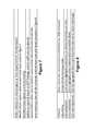
- 1) Take the summation of the squares of the past J samples.
- 2) If any past samples have been declared “valid” pulses, remove these D terms from the sum.
- 3) Divide this summation by the number of samples remaining in the sum after subtraction and denote the result by Q.
- 4) Set T=α/√{square root over (Q)}, where α is the desired number of standard deviations.
codes (where n is the maximum delay). So, for an example where n=60, this provides about 12 bits of isolation. Therefore, a triplet code enhances isolation against interfering ladars.
x+y>T 1)
x<τy 2)
y<τx 3)
Note that 2),3) combined is the same as computing max(x/y,y/x)<τ (see discussion below relating to a triple comparator approach).
where “y(i)” represents the value of sample i in the signal (where y(k) corresponds to the signal at224 and y(k−L) corresponds to the delayed signal228). This would be an excellent filter, and in fact is equal to the triple comparator with an adaptive threshold which we now show. A reason as to why this is a good detector is that the top term inside the absolute value is zero if we have no noise and two valid pulses. If we have pure noise then the denominator is an estimate of the noise standard deviation, and hence we have a test which is independent of noise variance [constant false alarm rate] and also gives 100% correct detection, 0% false alarms as the noise vanishes. This latter is called a consistent test in the statistics literature. Let us square both sides of the above expression. We obtain, when y(k)>y(k−L), letting
after algebra:
Since the left hand side is monotonic 0<ω<1, we can replace τ′ with some other threshold and obtain ω<1 or y(k)<τy(k−L). We conclude that the detector in equation (1) is equivalent to the detector in
This then defines a funnel as evidenced by properties of conic sections. We only need360 to determine how to set thresholds, and the circuit suffices to deliver our decision.
- 1) Count how often the first stage [screening] in
FIG. 2D is triggered, - 2) Count how often the probing stage rejects the pulse.
- 3) Apply the formulas in
FIG. 3C to the results. - 4) If the false alarms are larger than noise-only dictates, and the double and triple leaks are high, redo the hash codes, either in length or delay assignment.
- 1) Count how often the first stage [screening] in
Claims (47)
Priority Applications (1)
| Application Number | Priority Date | Filing Date | Title |
|---|---|---|---|
| US15/896,233US10386467B2 (en) | 2017-02-17 | 2018-02-14 | Ladar pulse deconfliction apparatus |
Applications Claiming Priority (2)
| Application Number | Priority Date | Filing Date | Title |
|---|---|---|---|
| US201762460520P | 2017-02-17 | 2017-02-17 | |
| US15/896,233US10386467B2 (en) | 2017-02-17 | 2018-02-14 | Ladar pulse deconfliction apparatus |
Publications (2)
| Publication Number | Publication Date |
|---|---|
| US20180238998A1 US20180238998A1 (en) | 2018-08-23 |
| US10386467B2true US10386467B2 (en) | 2019-08-20 |
Family
ID=63166563
Family Applications (7)
| Application Number | Title | Priority Date | Filing Date |
|---|---|---|---|
| US15/896,233ActiveUS10386467B2 (en) | 2017-02-17 | 2018-02-14 | Ladar pulse deconfliction apparatus |
| US15/896,219ActiveUS10379205B2 (en) | 2017-02-17 | 2018-02-14 | Ladar pulse deconfliction method |
| US15/896,262Active2039-11-21US11092676B2 (en) | 2017-02-17 | 2018-02-14 | Method and system for optical data communication via scanning ladar |
| US15/896,241ActiveUS10185028B2 (en) | 2017-02-17 | 2018-02-14 | Method and system for ladar pulse deconfliction using delay code selection |
| US15/896,254ActiveUS10209349B2 (en) | 2017-02-17 | 2018-02-14 | Method and system for ladar pulse deconfliction to detect and track other ladar systems |
| US17/394,104Active2038-04-10US11835658B2 (en) | 2017-02-17 | 2021-08-04 | Method and system for ladar pulse deconfliction |
| US18/234,491ActiveUS12265182B2 (en) | 2017-02-17 | 2023-08-16 | Method and system for optical data communication via ladar |
Family Applications After (6)
| Application Number | Title | Priority Date | Filing Date |
|---|---|---|---|
| US15/896,219ActiveUS10379205B2 (en) | 2017-02-17 | 2018-02-14 | Ladar pulse deconfliction method |
| US15/896,262Active2039-11-21US11092676B2 (en) | 2017-02-17 | 2018-02-14 | Method and system for optical data communication via scanning ladar |
| US15/896,241ActiveUS10185028B2 (en) | 2017-02-17 | 2018-02-14 | Method and system for ladar pulse deconfliction using delay code selection |
| US15/896,254ActiveUS10209349B2 (en) | 2017-02-17 | 2018-02-14 | Method and system for ladar pulse deconfliction to detect and track other ladar systems |
| US17/394,104Active2038-04-10US11835658B2 (en) | 2017-02-17 | 2021-08-04 | Method and system for ladar pulse deconfliction |
| US18/234,491ActiveUS12265182B2 (en) | 2017-02-17 | 2023-08-16 | Method and system for optical data communication via ladar |
Country Status (8)
| Country | Link |
|---|---|
| US (7) | US10386467B2 (en) |
| EP (1) | EP3583442B1 (en) |
| JP (1) | JP7206206B2 (en) |
| KR (2) | KR102610986B1 (en) |
| CN (1) | CN110431439B (en) |
| AU (1) | AU2018220938B2 (en) |
| CA (1) | CA3053775A1 (en) |
| WO (1) | WO2018152201A1 (en) |
Cited By (19)
| Publication number | Priority date | Publication date | Assignee | Title |
|---|---|---|---|---|
| US10642029B2 (en) | 2016-02-18 | 2020-05-05 | Aeye, Inc. | Ladar transmitter with ellipsoidal reimager |
| US10641873B2 (en) | 2016-02-18 | 2020-05-05 | Aeye, Inc. | Method and apparatus for an adaptive ladar receiver |
| US10782393B2 (en) | 2016-02-18 | 2020-09-22 | Aeye, Inc. | Ladar receiver range measurement using distinct optical path for reference light |
| US10908262B2 (en) | 2016-02-18 | 2021-02-02 | Aeye, Inc. | Ladar transmitter with optical field splitter/inverter for improved gaze on scan area portions |
| US10908265B2 (en) | 2014-08-15 | 2021-02-02 | Aeye, Inc. | Ladar transmitter with feedback control of dynamic scan patterns |
| US11002857B2 (en) | 2017-09-15 | 2021-05-11 | Aeye, Inc. | Ladar system with intelligent selection of shot list frames based on field of view data |
| US11092676B2 (en) | 2017-02-17 | 2021-08-17 | Aeye, Inc. | Method and system for optical data communication via scanning ladar |
| US11300667B1 (en) | 2021-03-26 | 2022-04-12 | Aeye, Inc. | Hyper temporal lidar with dynamic laser control for scan line shot scheduling |
| US11467263B1 (en) | 2021-03-26 | 2022-10-11 | Aeye, Inc. | Hyper temporal lidar with controllable variable laser seed energy |
| US11480680B2 (en) | 2021-03-26 | 2022-10-25 | Aeye, Inc. | Hyper temporal lidar with multi-processor return detection |
| US11500093B2 (en) | 2021-03-26 | 2022-11-15 | Aeye, Inc. | Hyper temporal lidar using multiple matched filters to determine target obliquity |
| US11569834B2 (en) | 2020-07-28 | 2023-01-31 | AyDeeKay LLC | Time-interleaved dynamic-element matching analog-to-digital converter |
| US11604264B2 (en) | 2021-03-26 | 2023-03-14 | Aeye, Inc. | Switchable multi-lens Lidar receiver |
| US11630188B1 (en) | 2021-03-26 | 2023-04-18 | Aeye, Inc. | Hyper temporal lidar with dynamic laser control using safety models |
| US11635495B1 (en) | 2021-03-26 | 2023-04-25 | Aeye, Inc. | Hyper temporal lidar with controllable tilt amplitude for a variable amplitude scan mirror |
| US11933967B2 (en) | 2019-08-22 | 2024-03-19 | Red Creamery, LLC | Distally actuated scanning mirror |
| US12123950B2 (en) | 2016-02-15 | 2024-10-22 | Red Creamery, LLC | Hybrid LADAR with co-planar scanning and imaging field-of-view |
| US12399279B1 (en) | 2016-02-15 | 2025-08-26 | Red Creamery Llc | Enhanced hybrid LIDAR with high-speed scanning |
| US12399278B1 (en) | 2016-02-15 | 2025-08-26 | Red Creamery Llc | Hybrid LIDAR with optically enhanced scanned laser |
Families Citing this family (38)
| Publication number | Priority date | Publication date | Assignee | Title |
|---|---|---|---|---|
| US12153156B2 (en)* | 2017-01-13 | 2024-11-26 | Origin Research Wireless, Inc. | Method, apparatus, and system for wireless monitoring with improved accuracy |
| US10845474B1 (en)* | 2017-05-04 | 2020-11-24 | Rockwell Collins, Inc. | Pulse identification in a light detection and ranging, sonar, or radar system |
| US11007031B2 (en) | 2018-08-14 | 2021-05-18 | Verb Surgical Inc. | Setup of surgical robots using an augmented mirror display |
| JP7303616B2 (en)* | 2018-08-30 | 2023-07-05 | 株式会社トプコン | Light wave distance meter and light wave distance measuring method |
| US11493615B2 (en)* | 2018-09-11 | 2022-11-08 | Velodyne Lidar Usa, Inc. | Systems and methods for detecting an electromagnetic signal in a constant interference environment |
| DE102018126522A1 (en) | 2018-10-24 | 2020-04-30 | Blickfeld GmbH | Runtime-based distance measurement using modulated pulse trains of laser pulses |
| US10598788B1 (en) | 2018-10-25 | 2020-03-24 | Aeye, Inc. | Adaptive control of Ladar shot selection using spatial index of prior Ladar return data |
| DE102018129246B4 (en) | 2018-11-21 | 2020-10-15 | Infineon Technologies Ag | INTERFERENCE DETECTION AND REDUCTION FOR LIDAR SYSTEMS |
| US11486978B2 (en) | 2018-12-26 | 2022-11-01 | Intel Corporation | Technology to support the coexistence of multiple independent lidar sensors |
| EP3918369A4 (en)* | 2019-03-05 | 2023-01-25 | Waymo Llc | SYSTEMS AND METHODS FOR REAL-TIME CALIBRATION OF LIDAR RANGE |
| US11947041B2 (en) | 2019-03-05 | 2024-04-02 | Analog Devices, Inc. | Coded optical transmission for optical detection |
| CN109917672B (en)* | 2019-03-29 | 2022-04-12 | 中国人民解放军93216部队 | Semi-physical simulation system and method for navigation and control loop |
| US10921450B2 (en) | 2019-04-24 | 2021-02-16 | Aeye, Inc. | Ladar system and method with frequency domain shuttering |
| CN112740066B (en)* | 2019-05-31 | 2023-08-04 | 深圳市速腾聚创科技有限公司 | Anti-interference processing method and device for multi-pulse laser radar system |
| US11153010B2 (en) | 2019-07-02 | 2021-10-19 | Waymo Llc | Lidar based communication |
| CN112639517B (en)* | 2019-09-06 | 2023-07-14 | 深圳市速腾聚创科技有限公司 | Laser radar ranging method, laser radar ranging device, computer equipment and storage medium |
| CN110988807B (en)* | 2019-11-22 | 2021-10-19 | 北京未感科技有限公司 | Device, system and method for eliminating circuit spike interference |
| US11681038B2 (en)* | 2019-12-19 | 2023-06-20 | Woven Planet North America, Inc. | Reducing radar signal interference based on semi-random and random configuration |
| WO2021236201A2 (en)* | 2020-03-05 | 2021-11-25 | OPSYS Tech Ltd. | Noise filtering system and method for solid-state lidar |
| CN113534180A (en)* | 2020-04-14 | 2021-10-22 | 华为技术有限公司 | A TOF measurement method and device for time of flight |
| US11977165B2 (en)* | 2020-08-10 | 2024-05-07 | Waymo Llc | Self-reflection filtering |
| US20220091236A1 (en)* | 2020-08-10 | 2022-03-24 | Cepton Technologies, Inc. | Techniques for detecting and mitigating interference among multiple lidar sensors |
| KR102816578B1 (en) | 2020-08-14 | 2025-06-04 | 삼성전자주식회사 | Duty adjustment circuit, and delay locked loop circuit and semiconductor memory device having the same |
| CN114325726B (en)* | 2020-09-27 | 2022-12-13 | 北京一径科技有限公司 | Anti-crosstalk processing method of laser radar, storage medium and laser radar |
| CN113589304B (en)* | 2020-09-27 | 2022-08-16 | 北京一径科技有限公司 | Anti-crosstalk processing method and device for laser radar and storage medium |
| KR20230074273A (en)* | 2020-10-13 | 2023-05-26 | 레드 리더 테크놀로지스, 인크. | lidar system and operation method |
| US12105200B2 (en)* | 2020-10-30 | 2024-10-01 | Waymo Llc | Detecting retroreflectors in NIR images to control LIDAR scan |
| DE102020132971B4 (en)* | 2020-12-10 | 2024-10-10 | Osram Gmbh | LIGHT DETECTION SYSTEM AND METHOD THEREFOR |
| US12222424B2 (en) | 2021-03-15 | 2025-02-11 | Lg Innotek Co., Ltd. | Reducing coexistence interference for light detection and ranging |
| CN113009455B (en)* | 2021-04-14 | 2022-06-03 | 吉林大学 | A method and system for improving the accuracy of pulsed laser ranging |
| US20230003852A1 (en)* | 2021-06-30 | 2023-01-05 | Waymo Llc | Systems and Methods for Retroreflector Mitigation Using Lidar |
| WO2023039733A1 (en)* | 2021-09-14 | 2023-03-23 | 华为技术有限公司 | Signal processing method and related apparatus |
| KR102608534B1 (en)* | 2021-10-28 | 2023-12-04 | 전남대학교산학협력단 | LiDAR ANTI-INTERFERENCE DEVICE USING MULTI-PULSE |
| JPWO2023144983A1 (en)* | 2022-01-28 | 2023-08-03 | ||
| KR102761103B1 (en) | 2022-02-17 | 2025-02-03 | 한만경 | Frequency Interference Prevention System Between Adjacent Traffic Radars and Method using the same |
| US20230358861A1 (en)* | 2022-05-04 | 2023-11-09 | Luminar, Llc | Dual-wavelength lidar system with coincidence detection and pulse encoding |
| CN115128561B (en)* | 2022-07-21 | 2024-11-22 | 四川嘉义索隐科技有限公司 | A radar countermeasure equipment effectiveness evaluation method |
| KR102611098B1 (en)* | 2023-02-28 | 2023-12-06 | 이화여자대학교 산학협력단 | Path planning method of unmanned aerial vehicle for traffic service and path planning apparatus |
Citations (95)
| Publication number | Priority date | Publication date | Assignee | Title |
|---|---|---|---|---|
| US4579430A (en) | 1982-12-11 | 1986-04-01 | Carl-Zeiss-Stiftung | Method and apparatus for forming an image of the ocular fundus |
| US5552893A (en) | 1993-09-17 | 1996-09-03 | Mitsubishi Denki Kabushiki Kaisha | Distance measuring apparatus |
| US5625644A (en) | 1991-12-20 | 1997-04-29 | Myers; David J. | DC balanced 4B/8B binary block code for digital data communications |
| US5638164A (en) | 1994-08-09 | 1997-06-10 | Development Authority, Rafael State of Israel--Ministry of Defense Armament | Apparatus and method for laser imaging |
| US5808775A (en) | 1996-03-13 | 1998-09-15 | Minolta Co., Ltd. | Laser beam scanning optical apparatus |
| US5815250A (en)* | 1997-05-27 | 1998-09-29 | Coherent Technologies, Inc. | Doublet pulse coherent laser radar for precision range and velocity measurements |
| US5831719A (en) | 1996-04-12 | 1998-11-03 | Holometrics, Inc. | Laser scanning system |
| US6031601A (en) | 1998-07-08 | 2000-02-29 | Trimble Navigation Limited | Code-space optical electronic distance meter |
| US6245590B1 (en) | 1999-08-05 | 2001-06-12 | Microvision Inc. | Frequency tunable resonant scanner and method of making |
| US6288816B1 (en) | 1994-10-26 | 2001-09-11 | University Of Washington | Miniature optical scanner for a two axis scanning system |
| US20030122687A1 (en) | 2001-12-27 | 2003-07-03 | Philips Electronics North America Corportion | Computer vision based parking assistant |
| US20030151542A1 (en) | 2001-01-31 | 2003-08-14 | Siegbert Steinlechner | Radar device and method for coding a radar device |
| WO2004034084A1 (en) | 2002-10-10 | 2004-04-22 | Qinetiq Limited | Bistatic laser radar apparatus |
| US6847462B1 (en) | 1996-04-24 | 2005-01-25 | Leica Geosystems Hds, Inc. | Integrated system for quickly and accurately imaging and modeling three-dimensional objects |
| US20050057654A1 (en) | 2003-08-28 | 2005-03-17 | Byren Robert W. | Synthetic aperture ladar system and method using real-time holography |
| US6926227B1 (en)* | 1977-04-27 | 2005-08-09 | Bae Systems Information And Electronics Systems Integration Inc. | Extended range, light weight laser target designator |
| US20060007362A1 (en) | 2004-06-09 | 2006-01-12 | Samsung Electronics Co., Ltd. | Apparatus for and method of scaling a scanning angle and image projection apparatus incorporating the same |
| WO2006076474A1 (en) | 2005-01-13 | 2006-07-20 | Arete Associates | Optical system with wavefront sensor |
| US20060176468A1 (en) | 2003-09-15 | 2006-08-10 | Anderson Noel W | Optical range finder with directed attention |
| US20060197936A1 (en) | 2005-03-01 | 2006-09-07 | Liebman Lionel D | Single detector receiver for multi-beam LADAR systems |
| US20060227315A1 (en) | 2005-04-11 | 2006-10-12 | Agilent Technologies, Inc. | Time-of-flight measurement using pulse sequences |
| US20060265147A1 (en) | 2005-04-28 | 2006-11-23 | Sanyo Electric Co., Ltd. | Detection device |
| US7236235B2 (en) | 2004-07-06 | 2007-06-26 | Dimsdale Engineering, Llc | System and method for determining range in 3D imaging systems |
| WO2008008970A2 (en) | 2006-07-13 | 2008-01-17 | Velodyne Acoustics, Inc | High definition lidar system |
| US20080136626A1 (en) | 2006-10-02 | 2008-06-12 | Edison Hudson | Threat detection sensor suite |
| US20080159591A1 (en) | 2007-01-03 | 2008-07-03 | Science Applications International Corporation | Human detection with imaging sensors |
| US20090059201A1 (en) | 2007-08-28 | 2009-03-05 | Science Applications International Corporation | Full-Field Light Detection and Ranging Imaging System |
| US20090128864A1 (en) | 2007-11-19 | 2009-05-21 | Osamu Inage | Image reading device and image forming apparatus |
| US20090292468A1 (en) | 2008-03-25 | 2009-11-26 | Shunguang Wu | Collision avoidance method and system using stereo vision and radar sensor fusion |
| US20100027602A1 (en) | 2008-07-31 | 2010-02-04 | United States Of America As Represented By The Administrator Of The National Aeronautics And Spac | Time delay and distance measurement |
| US20100053715A1 (en) | 2006-10-30 | 2010-03-04 | O'neill James | Scanning system for lidar |
| US7701558B2 (en) | 2006-09-22 | 2010-04-20 | Leica Geosystems Ag | LIDAR system |
| US7800736B2 (en) | 2005-10-05 | 2010-09-21 | Utah State University | System and method for improving lidar data fidelity using pixel-aligned lidar/electro-optic data |
| US7894044B1 (en) | 2008-03-11 | 2011-02-22 | Oceanit Laboratories, Inc. | Laser for coherent LIDAR |
| US20110066262A1 (en) | 2008-01-22 | 2011-03-17 | Carnegie Mellon University | Apparatuses, Systems, and Methods for Apparatus Operation and Remote Sensing |
| US7944548B2 (en) | 2006-03-07 | 2011-05-17 | Leica Geosystems Ag | Increasing measurement rate in time of flight measurement apparatuses |
| US20110153367A1 (en) | 2009-12-17 | 2011-06-23 | Hartford Fire Insurance Company | Systems and methods for linking vehicles to telematics-enabled portable devices |
| US20110149360A1 (en) | 2007-08-19 | 2011-06-23 | Btendo Ltd. | Optical device for projection of optical beams |
| US20110149268A1 (en) | 2009-12-17 | 2011-06-23 | Marchant Alan B | Dynamic 3d wind mapping system and method |
| US20110260036A1 (en) | 2010-02-22 | 2011-10-27 | Baraniuk Richard G | Temporally- And Spatially-Resolved Single Photon Counting Using Compressive Sensing For Debug Of Integrated Circuits, Lidar And Other Applications |
| US8081301B2 (en) | 2009-10-08 | 2011-12-20 | The United States Of America As Represented By The Secretary Of The Army | LADAR transmitting and receiving system and method |
| US20110317147A1 (en) | 2010-06-23 | 2011-12-29 | U.S.A. As Represented By The Administrator Of The National Aeronautics And Space Administration | Time Shifted PN Codes for CW LIDAR, RADAR, and SONAR |
| US8120754B2 (en) | 2009-02-19 | 2012-02-21 | Northrop Grumman Systems Corporation | Light detection and ranging apparatus |
| US20120044093A1 (en) | 2010-08-20 | 2012-02-23 | Denso International America, Inc. | Combined time-of-flight and image sensor systems |
| US20120044476A1 (en) | 2008-05-09 | 2012-02-23 | Ball Aerospace & Technologies Corp. | Systems and methods of scene and action capture using imaging system incorporating 3d lidar |
| US20120236379A1 (en) | 2010-08-23 | 2012-09-20 | Lighttime, Llc | Ladar using mems scanning |
| US20120249996A1 (en) | 2011-03-31 | 2012-10-04 | Denso Wave Incorporated | Laser radar for three-dimensional scanning |
| US20120257186A1 (en) | 2011-04-07 | 2012-10-11 | Riegl Laser Measurement Systems Gmbh | Method for Measuring Distances |
| US8427657B2 (en) | 2008-08-08 | 2013-04-23 | Mirrorcle Technologies, Inc. | Device for optical imaging, tracking, and position measurement with a scanning MEMS mirror |
| US20140021354A1 (en) | 2012-07-18 | 2014-01-23 | Toshiba Medical Systems Corporation | Apparatus and method for channel count reduction in solid-state-based positron emission tomography |
| US20140078514A1 (en) | 2010-10-22 | 2014-03-20 | Neptec Design Group Ltd. | Wide angle bistatic scanning optical ranging sensor |
| CN103885065A (en) | 2014-03-21 | 2014-06-25 | 中国科学院上海光学精密机械研究所 | Dual-wavelength dipulse non-fuzzy laser ranging device |
| US20140211194A1 (en) | 2013-01-27 | 2014-07-31 | Quanergy Systems, Inc. | Cost-effective lidar sensor for multi-signal detection, weak signal detection and signal disambiguation and method of using same |
| US20140291491A1 (en) | 2012-03-22 | 2014-10-02 | Primesense Ltd. | Calibration of time-of-flight measurement using stray reflections |
| US20140350836A1 (en) | 2013-05-24 | 2014-11-27 | Advance Scientific Concepts, Inc. | Automotive auxiliary ladar sensor |
| US20150081211A1 (en) | 2013-09-17 | 2015-03-19 | GM Global Technologies Operations LLC | Sensor-aided vehicle positioning system |
| US9069061B1 (en) | 2011-07-19 | 2015-06-30 | Ball Aerospace & Technologies Corp. | LIDAR with analog memory |
| US9085354B1 (en) | 2013-04-23 | 2015-07-21 | Google Inc. | Systems and methods for vertical takeoff and/or landing |
| US9128190B1 (en) | 2013-03-06 | 2015-09-08 | Google Inc. | Light steering device with an array of oscillating reflective slats |
| US20150331113A1 (en) | 2013-03-08 | 2015-11-19 | Advanced Scientific Concepts, Inc. | Ladar enabled impact mitigation system |
| US20150369920A1 (en) | 2014-06-20 | 2015-12-24 | Funai Electric Co., Ltd. | Electronic apparatus and method for measuring direction of output laser light |
| US20150378187A1 (en) | 2014-06-28 | 2015-12-31 | John Heck | Solid state lidar circuit |
| US20150378011A1 (en) | 2014-06-27 | 2015-12-31 | Hrl Laboratories Llc | Compressive scanning lidar |
| US20160003946A1 (en) | 2014-07-03 | 2016-01-07 | Advanced Scientific Concepts, Inc. | Ladar sensor for a dense environment |
| US9261881B1 (en) | 2013-08-01 | 2016-02-16 | Google Inc. | Filtering noisy/high-intensity regions in laser-based lane marker detection |
| US20160047898A1 (en) | 2014-08-15 | 2016-02-18 | US LADAR, Inc. | Method and System for Ladar Transmission with Spiral Dynamic Scan Patterns |
| US9278689B1 (en) | 2014-11-13 | 2016-03-08 | Toyota Motor Engineering & Manufacturing North America, Inc. | Autonomous vehicle detection of and response to emergency vehicles |
| US9285477B1 (en) | 2013-01-25 | 2016-03-15 | Apple Inc. | 3D depth point cloud from timing flight of 2D scanned light beam pulses |
| US9305219B2 (en) | 2014-01-23 | 2016-04-05 | Mitsubishi Electric Research Laboratories, Inc. | Method for estimating free space using a camera system |
| US9315178B1 (en) | 2012-04-13 | 2016-04-19 | Google Inc. | Model checking for autonomous vehicles |
| US9360554B2 (en) | 2014-04-11 | 2016-06-07 | Facet Technology Corp. | Methods and apparatus for object detection and identification in a multiple detector lidar array |
| US9383753B1 (en) | 2012-09-26 | 2016-07-05 | Google Inc. | Wide-view LIDAR with areas of special attention |
| US9437053B2 (en) | 2014-01-06 | 2016-09-06 | Geodigital International Inc. | Determining portions of a roadway model requiring updating |
| US20160293647A1 (en) | 2015-03-30 | 2016-10-06 | Hamilton Sundstrand Corporation | Digital imaging and pulse detection pixel |
| US20170158239A1 (en) | 2014-06-04 | 2017-06-08 | Commissariat A L'energie Atomique Et Aux Energies Alternatives | Parking assistance device and vehicle provided with such a device |
| US20170199280A1 (en) | 2015-03-27 | 2017-07-13 | Sensors Unlimited, Inc. | System and method of tracking multiple targets designated by pulse-coded lasers |
| US20170205873A1 (en) | 2012-02-15 | 2017-07-20 | Apple Inc. | Scanning depth engine |
| US20170219695A1 (en) | 2016-01-31 | 2017-08-03 | Velodyne Lidar, Inc. | Multiple Pulse, LIDAR Based 3-D Imaging |
| US20170234973A1 (en) | 2016-02-15 | 2017-08-17 | Airborne Hydrography Ab | Low photon count timing |
| US20170242105A1 (en) | 2016-02-18 | 2017-08-24 | Aeye, Inc. | Adaptive Ladar Receiving Method |
| WO2017143217A1 (en) | 2016-02-18 | 2017-08-24 | Aeye, Inc. | Adaptive ladar receiver |
| US20170242103A1 (en) | 2016-02-18 | 2017-08-24 | Aeye, Inc. | Ladar Transmitter with Optical Field Splitter/Inverter for Improved Gaze on Scan Area Portions |
| WO2017143183A1 (en) | 2016-02-18 | 2017-08-24 | Aeye, Inc. | Ladar transmitter with improved gaze on scan area portions |
| US20170242108A1 (en) | 2016-02-18 | 2017-08-24 | Aeye, Inc. | Method and Apparatus for an Adaptive Ladar Receiver |
| US20170263048A1 (en) | 2012-03-07 | 2017-09-14 | Willow Garage, Inc. | Point cloud data hierarchy |
| US20170269198A1 (en) | 2016-03-21 | 2017-09-21 | Velodyne Lidar, Inc. | LIDAR Based 3-D Imaging With Varying Illumination Field Density |
| US20170269197A1 (en) | 2016-03-21 | 2017-09-21 | Velodyne Lidar, Inc. | LIDAR Based 3-D Imaging With Varying Illumination Intensity |
| US20170269215A1 (en) | 2016-03-19 | 2017-09-21 | Velodyne Lidar, Inc. | Integrated Illumination And Detection For LIDAR Based 3-D Imaging |
| US20170269209A1 (en) | 2016-03-21 | 2017-09-21 | Velodyne Lidar, Inc. | LIDAR Based 3-D Imaging With Varying Pulse Repetition |
| US20170307876A1 (en) | 2016-02-18 | 2017-10-26 | Aeye, Inc. | Ladar Transmitter with Optical Field Splitter/Inverter |
| US20180031703A1 (en)* | 2016-07-21 | 2018-02-01 | Z-Senz Llc | Systems, Devices, and/or Methods for Encoded Time of Flight Light Detection and Ranging |
| US9958545B2 (en) | 2015-11-30 | 2018-05-01 | Luminar Technologies, Inc. | Lidar system |
| US20180143324A1 (en) | 2016-09-20 | 2018-05-24 | Innoviz Technologies Ltd. | Optical budget apportionment in lidar |
| US10007001B1 (en) | 2017-03-28 | 2018-06-26 | Luminar Technologies, Inc. | Active short-wave infrared four-dimensional camera |
| US20180239000A1 (en) | 2017-02-17 | 2018-08-23 | Aeye, Inc. | Method and System for Ladar Pulse Deconfliction Using Delay Code Selection |
Family Cites Families (97)
| Publication number | Priority date | Publication date | Assignee | Title |
|---|---|---|---|---|
| US4017146A (en)* | 1976-03-04 | 1977-04-12 | The United States Of America As Represented By The Secretary Of The Navy | Transmitter for use in a laser communication and ranging system |
| JPS5626273A (en)* | 1979-08-10 | 1981-03-13 | Nippon Denso Co Ltd | Car safety control method |
| JPS6264974A (en)* | 1985-09-18 | 1987-03-24 | Nec Corp | Laser alarm apparatus |
| CA1305648C (en) | 1986-11-04 | 1992-07-28 | Fritz Krusi | Apparatus for machining a workpiece of wood, in particular wooden beams |
| US4888785A (en)* | 1988-01-19 | 1989-12-19 | Bell Communications Research, Inc. | Miniature integrated optical beam splitter |
| US5408351A (en)* | 1992-10-15 | 1995-04-18 | At&T Corp. | Optical communication system |
| JP3183592B2 (en)* | 1993-07-15 | 2001-07-09 | 三菱電機株式会社 | Distance measuring device |
| JPH0798381A (en) | 1993-08-06 | 1995-04-11 | Omron Corp | Scanning type distance measuring device, vehicle mounted with it, and light detecting device |
| US5596600A (en) | 1995-04-06 | 1997-01-21 | Mayflower Communications Company, Inc. | Standalone canceller of narrow band interference for spread spectrum receivers |
| JPH10160465A (en)* | 1996-12-04 | 1998-06-19 | Futaba Corp | Distance measuring system |
| JPH11153664A (en) | 1997-09-30 | 1999-06-08 | Sumitomo Electric Ind Ltd | Object detection device using repetitive pulsed light |
| US5870181A (en) | 1997-10-28 | 1999-02-09 | Alliant Defense Electronics Systems, Inc. | Acoustic optical scanning of linear detector array for laser radar |
| US6205275B1 (en) | 1998-06-22 | 2001-03-20 | Brian E. Melville | Fiber optic image transfer assembly and method of using |
| JP3832101B2 (en) | 1998-08-05 | 2006-10-11 | 株式会社デンソー | Distance measuring device |
| JP2000322696A (en) | 1999-05-07 | 2000-11-24 | Honda Motor Co Ltd | Platoon running control device |
| AU2000267433A1 (en) | 2000-05-16 | 2001-11-26 | Nortel Networks Limited | Cellular communications system receivers |
| AU2002339874A1 (en) | 2001-05-23 | 2002-12-03 | Canesta, Inc. | Enhanced dynamic range conversion in 3-d imaging |
| FR2835120B1 (en) | 2002-01-21 | 2006-10-20 | Evolium Sas | METHOD AND DEVICE FOR PREPARING SIGNALS TO BE COMPARED TO ESTABLISH PRE-DISTORTION ON THE INPUT OF AN AMPLIFIER |
| JP2003256820A (en) | 2002-03-05 | 2003-09-12 | Casio Comput Co Ltd | Image reading apparatus and sensitivity setting method thereof |
| US6836320B2 (en) | 2002-10-23 | 2004-12-28 | Ae Systems Information And Electronic Systems Integration Inc. | Method and apparatus for active boresight correction |
| JP2004157044A (en) | 2002-11-07 | 2004-06-03 | Nippon Signal Co Ltd:The | Scanning type laser radar |
| CN1273841C (en) | 2002-12-24 | 2006-09-06 | 中国科学院上海技术物理研究所 | Adaptive variable-speed scanning laser imager |
| US6870815B2 (en) | 2003-01-30 | 2005-03-22 | Atheros Communications, Inc. | Methods for implementing a dynamic frequency selection (DFS) and a temporary channel selection feature for WLAN devices |
| US7436494B1 (en) | 2003-03-28 | 2008-10-14 | Irvine Sensors Corp. | Three-dimensional ladar module with alignment reference insert circuitry |
| US6704619B1 (en) | 2003-05-24 | 2004-03-09 | American Gnc Corporation | Method and system for universal guidance and control of automated machines |
| JP2005043868A (en)* | 2003-07-09 | 2005-02-17 | Sony Corp | Image projection device and image projection method |
| US7643966B2 (en) | 2004-03-10 | 2010-01-05 | Leica Geosystems Ag | Identification of 3D surface points using context-based hypothesis testing |
| ITRM20040249A1 (en) | 2004-05-17 | 2004-08-17 | Univ Roma | HIGH PRECISION SURVEILLANCE SYSTEM BY MULTILATERATION OF SSR SIGNALS. |
| JP3962929B2 (en) | 2004-05-18 | 2007-08-22 | 防衛省技術研究本部長 | Laser distance image generating apparatus and method |
| JP2006118924A (en) | 2004-10-20 | 2006-05-11 | Tdk Corp | Pulse radar system |
| US7038608B1 (en) | 2004-12-16 | 2006-05-02 | Valeo Raytheon Systems, Inc. | Digital to analog converter |
| US7532311B2 (en) | 2005-04-06 | 2009-05-12 | Lockheed Martin Coherent Technologies, Inc. | Efficient lidar with flexible target interrogation pattern |
| JP2006329971A (en) | 2005-04-27 | 2006-12-07 | Sanyo Electric Co Ltd | Detector |
| US20090242468A1 (en) | 2005-10-17 | 2009-10-01 | Tim Corben | System for Controlling the Concentration of a Detrimental Substance in a Sewer Network |
| US7397019B1 (en) | 2005-10-19 | 2008-07-08 | Alliant Techsystems, Inc. | Light sensor module, focused light sensor array, and an air vehicle so equipped |
| US8958057B2 (en) | 2006-06-27 | 2015-02-17 | Arete Associates | Camera-style lidar setup |
| US7579593B2 (en) | 2006-07-25 | 2009-08-25 | Panasonic Corporation | Night-vision imaging apparatus, control method of the same, and headlight module |
| EP1901093B1 (en) | 2006-09-15 | 2018-11-14 | Triple-IN Holding AG | Capture of distance images |
| US7878657B2 (en) | 2007-06-27 | 2011-02-01 | Prysm, Inc. | Servo feedback control based on invisible scanning servo beam in scanning beam display systems with light-emitting screens |
| US20090318815A1 (en) | 2008-05-23 | 2009-12-24 | Michael Barnes | Systems and methods for hyperspectral medical imaging |
| IL200332A0 (en)* | 2008-08-19 | 2010-04-29 | Rosemount Aerospace Inc | Lidar system using a pseudo-random pulse sequence |
| US20100204964A1 (en) | 2009-02-09 | 2010-08-12 | Utah State University | Lidar-assisted multi-image matching for 3-d model and sensor pose refinement |
| US9091754B2 (en)* | 2009-09-02 | 2015-07-28 | Trimble A.B. | Distance measurement methods and apparatus |
| ES2387484B1 (en) | 2009-10-15 | 2013-08-02 | Alfa Imaging S.A. | SWEEP MULTIESPECTRAL SYSTEM. |
| US9008998B2 (en) | 2010-02-05 | 2015-04-14 | Trimble Navigation Limited | Systems and methods for processing mapping and modeling data |
| US8570405B2 (en) | 2010-08-11 | 2013-10-29 | Inview Technology Corporation | Determining light level variation in compressive imaging by injecting calibration patterns into pattern sequence |
| US8736818B2 (en) | 2010-08-16 | 2014-05-27 | Ball Aerospace & Technologies Corp. | Electronically steered flash LIDAR |
| CN102023082A (en) | 2010-09-29 | 2011-04-20 | 中国科学院上海光学精密机械研究所 | Two-dimensional pointing mirror dynamic performance detection device and detection method |
| EP2469301A1 (en) | 2010-12-23 | 2012-06-27 | André Borowski | Methods and devices for generating a representation of a 3D scene at very high speed |
| JP2012202776A (en) | 2011-03-24 | 2012-10-22 | Toyota Central R&D Labs Inc | Distance measuring device |
| JP5702230B2 (en) | 2011-06-01 | 2015-04-15 | 日本信号株式会社 | Optical scanning device |
| JP5978565B2 (en) | 2011-06-30 | 2016-08-24 | 富士通株式会社 | Monitoring device and monitoring method |
| WO2014145918A1 (en) | 2013-03-15 | 2014-09-18 | Peloton Technology, Inc. | Vehicle platooning systems and methods |
| US10027952B2 (en) | 2011-08-04 | 2018-07-17 | Trx Systems, Inc. | Mapping and tracking system with features in three-dimensional space |
| CN102565807A (en)* | 2011-12-23 | 2012-07-11 | 中国科学院长春光学精密机械与物理研究所 | Laser heterodyne device based on photon counting statistics of MPPC (multi-pixel photon counter) |
| JP2013156139A (en) | 2012-01-30 | 2013-08-15 | Ihi Corp | Moving object detecting apparatus and moving object detecting method |
| US9915726B2 (en)* | 2012-03-16 | 2018-03-13 | Continental Advanced Lidar Solutions Us, Llc | Personal LADAR sensor |
| EP2708913A1 (en) | 2012-09-18 | 2014-03-19 | Sick Ag | Opto-electronic sensor and object detection method |
| EP2708914A1 (en) | 2012-09-18 | 2014-03-19 | Sick Ag | Optoelectronic sensor and method for recording a depth map |
| JP6236758B2 (en) | 2012-10-09 | 2017-11-29 | 株式会社豊田中央研究所 | Optical distance measuring device |
| CN103033806A (en) | 2012-12-27 | 2013-04-10 | 山东理工大学 | Method and device for airborne laser scanning flying height change real-time compensation |
| ES2512965B2 (en) | 2013-02-13 | 2015-11-24 | Universitat Politècnica De Catalunya | System and method to scan a surface and computer program that implements the method |
| US9251587B2 (en) | 2013-04-05 | 2016-02-02 | Caterpillar Inc. | Motion estimation utilizing range detection-enhanced visual odometry |
| US9674413B1 (en)* | 2013-04-17 | 2017-06-06 | Rockwell Collins, Inc. | Vision system and method having improved performance and solar mitigation |
| CN103324945B (en) | 2013-07-08 | 2016-12-28 | 南京大学 | A kind of forest point cloud classifications method based on pattern recognition |
| JP2015014757A (en) | 2013-07-08 | 2015-01-22 | 株式会社豊田中央研究所 | Scanning optical system, optical scanning device, and ranging device |
| US9626566B2 (en) | 2014-03-19 | 2017-04-18 | Neurala, Inc. | Methods and apparatus for autonomous robotic control |
| US9952323B2 (en) | 2014-04-07 | 2018-04-24 | Samsung Electronics Co., Ltd. | High resolution, high frame rate, low power image sensor |
| US20150334371A1 (en) | 2014-05-19 | 2015-11-19 | Rockwell Automation Technologies, Inc. | Optical safety monitoring with selective pixel array analysis |
| US10068373B2 (en) | 2014-07-01 | 2018-09-04 | Samsung Electronics Co., Ltd. | Electronic device for providing map information |
| WO2016025502A1 (en) | 2014-08-11 | 2016-02-18 | Gerard Dirk Smits | Three-dimensional triangulation and time-of-flight based tracking systems and methods |
| US9638801B2 (en) | 2014-11-24 | 2017-05-02 | Mitsubishi Electric Research Laboratories, Inc | Depth sensing using optical pulses and fixed coded aperature |
| US9692937B1 (en) | 2014-12-22 | 2017-06-27 | Accusoft Corporation | Methods and apparatus for identifying lines in an image and using identified lines |
| US9581967B1 (en) | 2015-01-07 | 2017-02-28 | Lockheed Martin Coherent Technologies, Inc. | Motion compensated multi-wavelength digital holography |
| JP6704607B2 (en) | 2015-03-11 | 2020-06-03 | 株式会社リコー | Imaging system, image processing system, moving body control system, moving body device, light projecting device, object detection method, object detection program |
| US10281581B2 (en)* | 2015-05-07 | 2019-05-07 | GM Global Technology Operations LLC | Lidar with optical communication |
| US10309607B2 (en) | 2015-05-18 | 2019-06-04 | Koninklijke Philips N.V. | Lighting system |
| US10289940B2 (en) | 2015-06-26 | 2019-05-14 | Here Global B.V. | Method and apparatus for providing classification of quality characteristics of images |
| US10527726B2 (en) | 2015-07-02 | 2020-01-07 | Texas Instruments Incorporated | Methods and apparatus for LIDAR with DMD |
| US10282591B2 (en) | 2015-08-24 | 2019-05-07 | Qualcomm Incorporated | Systems and methods for depth map sampling |
| EP3371625A4 (en) | 2015-11-05 | 2019-05-15 | Luminar Technologies, Inc. | LIDAR SYSTEM WITH ENHANCED SCAN SPEED FOR HIGH RESOLUTION DEPTH CARTOGRAPHY |
| EP3196593B1 (en) | 2016-01-21 | 2018-01-17 | Safran Vectronix AG | Stabilized observation with lrf function |
| KR20170096723A (en)* | 2016-02-17 | 2017-08-25 | 한국전자통신연구원 | Lidar system and multiple detection signal processing method thereof |
| US10134280B1 (en)* | 2016-02-23 | 2018-11-20 | Taehyun You | Vehicular notifications |
| US10473784B2 (en) | 2016-05-24 | 2019-11-12 | Veoneer Us, Inc. | Direct detection LiDAR system and method with step frequency modulation (FM) pulse-burst envelope modulation transmission and quadrature demodulation |
| US10797460B2 (en)* | 2016-07-13 | 2020-10-06 | Waymo Llc | Systems and methods for laser power interlocking |
| EP3513265B1 (en) | 2016-09-14 | 2024-09-18 | Nauto, Inc. | Method for near-collision determination |
| WO2018106360A2 (en) | 2016-10-31 | 2018-06-14 | Gerard Dirk Smits | Fast scanning lidar with dynamic voxel probing |
| WO2018091970A1 (en) | 2016-11-16 | 2018-05-24 | Innoviz Technologies Ltd. | Lidar systems and methods |
| US10942257B2 (en) | 2016-12-31 | 2021-03-09 | Innovusion Ireland Limited | 2D scanning high precision LiDAR using combination of rotating concave mirror and beam steering devices |
| US10209359B2 (en) | 2017-03-28 | 2019-02-19 | Luminar Technologies, Inc. | Adaptive pulse rate in a lidar system |
| US10545240B2 (en) | 2017-03-28 | 2020-01-28 | Luminar Technologies, Inc. | LIDAR transmitter and detector system using pulse encoding to reduce range ambiguity |
| US20180284234A1 (en) | 2017-03-29 | 2018-10-04 | Luminar Technologies, Inc. | Foveated Imaging in a Lidar System |
| US10677897B2 (en) | 2017-04-14 | 2020-06-09 | Luminar Technologies, Inc. | Combining lidar and camera data |
| US20180306927A1 (en) | 2017-04-21 | 2018-10-25 | GM Global Technology Operations LLC | Method and apparatus for pulse repetition sequence with high processing gain |
| US11002857B2 (en) | 2017-09-15 | 2021-05-11 | Aeye, Inc. | Ladar system with intelligent selection of shot list frames based on field of view data |
| JP2019052981A (en) | 2017-09-15 | 2019-04-04 | 株式会社東芝 | Distance measuring device |
- 2018
- 2018-02-14USUS15/896,233patent/US10386467B2/enactiveActive
- 2018-02-14CNCN201880018856.8Apatent/CN110431439B/enactiveActive
- 2018-02-14EPEP18754978.7Apatent/EP3583442B1/enactiveActive
- 2018-02-14KRKR1020237028999Apatent/KR102610986B1/enactiveActive
- 2018-02-14JPJP2019544663Apatent/JP7206206B2/enactiveActive
- 2018-02-14KRKR1020197026898Apatent/KR102572612B1/enactiveActive
- 2018-02-14USUS15/896,219patent/US10379205B2/enactiveActive
- 2018-02-14AUAU2018220938Apatent/AU2018220938B2/enactiveActive
- 2018-02-14CACA3053775Apatent/CA3053775A1/ennot_activeAbandoned
- 2018-02-14USUS15/896,262patent/US11092676B2/enactiveActive
- 2018-02-14USUS15/896,241patent/US10185028B2/enactiveActive
- 2018-02-14WOPCT/US2018/018179patent/WO2018152201A1/ennot_activeCeased
- 2018-02-14USUS15/896,254patent/US10209349B2/enactiveActive
- 2021
- 2021-08-04USUS17/394,104patent/US11835658B2/enactiveActive
- 2023
- 2023-08-16USUS18/234,491patent/US12265182B2/enactiveActive
Patent Citations (127)
| Publication number | Priority date | Publication date | Assignee | Title |
|---|---|---|---|---|
| US6926227B1 (en)* | 1977-04-27 | 2005-08-09 | Bae Systems Information And Electronics Systems Integration Inc. | Extended range, light weight laser target designator |
| US4579430A (en) | 1982-12-11 | 1986-04-01 | Carl-Zeiss-Stiftung | Method and apparatus for forming an image of the ocular fundus |
| US5625644A (en) | 1991-12-20 | 1997-04-29 | Myers; David J. | DC balanced 4B/8B binary block code for digital data communications |
| US5552893A (en) | 1993-09-17 | 1996-09-03 | Mitsubishi Denki Kabushiki Kaisha | Distance measuring apparatus |
| US5638164A (en) | 1994-08-09 | 1997-06-10 | Development Authority, Rafael State of Israel--Ministry of Defense Armament | Apparatus and method for laser imaging |
| US6288816B1 (en) | 1994-10-26 | 2001-09-11 | University Of Washington | Miniature optical scanner for a two axis scanning system |
| US5808775A (en) | 1996-03-13 | 1998-09-15 | Minolta Co., Ltd. | Laser beam scanning optical apparatus |
| US5831719A (en) | 1996-04-12 | 1998-11-03 | Holometrics, Inc. | Laser scanning system |
| US6847462B1 (en) | 1996-04-24 | 2005-01-25 | Leica Geosystems Hds, Inc. | Integrated system for quickly and accurately imaging and modeling three-dimensional objects |
| US5815250A (en)* | 1997-05-27 | 1998-09-29 | Coherent Technologies, Inc. | Doublet pulse coherent laser radar for precision range and velocity measurements |
| US6031601A (en) | 1998-07-08 | 2000-02-29 | Trimble Navigation Limited | Code-space optical electronic distance meter |
| US6245590B1 (en) | 1999-08-05 | 2001-06-12 | Microvision Inc. | Frequency tunable resonant scanner and method of making |
| US20030151542A1 (en) | 2001-01-31 | 2003-08-14 | Siegbert Steinlechner | Radar device and method for coding a radar device |
| US20030122687A1 (en) | 2001-12-27 | 2003-07-03 | Philips Electronics North America Corportion | Computer vision based parking assistant |
| WO2004034084A1 (en) | 2002-10-10 | 2004-04-22 | Qinetiq Limited | Bistatic laser radar apparatus |
| US20050057654A1 (en) | 2003-08-28 | 2005-03-17 | Byren Robert W. | Synthetic aperture ladar system and method using real-time holography |
| US20060176468A1 (en) | 2003-09-15 | 2006-08-10 | Anderson Noel W | Optical range finder with directed attention |
| US7206063B2 (en) | 2003-09-15 | 2007-04-17 | Deere & Company | Optical range finder with directed attention |
| US20060007362A1 (en) | 2004-06-09 | 2006-01-12 | Samsung Electronics Co., Ltd. | Apparatus for and method of scaling a scanning angle and image projection apparatus incorporating the same |
| US7236235B2 (en) | 2004-07-06 | 2007-06-26 | Dimsdale Engineering, Llc | System and method for determining range in 3D imaging systems |
| WO2006076474A1 (en) | 2005-01-13 | 2006-07-20 | Arete Associates | Optical system with wavefront sensor |
| US20060197936A1 (en) | 2005-03-01 | 2006-09-07 | Liebman Lionel D | Single detector receiver for multi-beam LADAR systems |
| US20060227315A1 (en) | 2005-04-11 | 2006-10-12 | Agilent Technologies, Inc. | Time-of-flight measurement using pulse sequences |
| US20060265147A1 (en) | 2005-04-28 | 2006-11-23 | Sanyo Electric Co., Ltd. | Detection device |
| US7800736B2 (en) | 2005-10-05 | 2010-09-21 | Utah State University | System and method for improving lidar data fidelity using pixel-aligned lidar/electro-optic data |
| US7944548B2 (en) | 2006-03-07 | 2011-05-17 | Leica Geosystems Ag | Increasing measurement rate in time of flight measurement apparatuses |
| WO2008008970A2 (en) | 2006-07-13 | 2008-01-17 | Velodyne Acoustics, Inc | High definition lidar system |
| US7701558B2 (en) | 2006-09-22 | 2010-04-20 | Leica Geosystems Ag | LIDAR system |
| US8896818B2 (en) | 2006-09-22 | 2014-11-25 | Leica Geosystems Ag | Lidar system |
| US20080136626A1 (en) | 2006-10-02 | 2008-06-12 | Edison Hudson | Threat detection sensor suite |
| US20100053715A1 (en) | 2006-10-30 | 2010-03-04 | O'neill James | Scanning system for lidar |
| US8072663B2 (en) | 2006-10-30 | 2011-12-06 | Autonosys Inc. | Scanning system for lidar |
| US20080159591A1 (en) | 2007-01-03 | 2008-07-03 | Science Applications International Corporation | Human detection with imaging sensors |
| US8228579B2 (en) | 2007-08-19 | 2012-07-24 | Btendo Ltd. | Optical device for projection of optical beams |
| US20110149360A1 (en) | 2007-08-19 | 2011-06-23 | Btendo Ltd. | Optical device for projection of optical beams |
| US20090059201A1 (en) | 2007-08-28 | 2009-03-05 | Science Applications International Corporation | Full-Field Light Detection and Ranging Imaging System |
| US20090128864A1 (en) | 2007-11-19 | 2009-05-21 | Osamu Inage | Image reading device and image forming apparatus |
| US20110066262A1 (en) | 2008-01-22 | 2011-03-17 | Carnegie Mellon University | Apparatuses, Systems, and Methods for Apparatus Operation and Remote Sensing |
| US7894044B1 (en) | 2008-03-11 | 2011-02-22 | Oceanit Laboratories, Inc. | Laser for coherent LIDAR |
| US20090292468A1 (en) | 2008-03-25 | 2009-11-26 | Shunguang Wu | Collision avoidance method and system using stereo vision and radar sensor fusion |
| US20120044476A1 (en) | 2008-05-09 | 2012-02-23 | Ball Aerospace & Technologies Corp. | Systems and methods of scene and action capture using imaging system incorporating 3d lidar |
| US20100027602A1 (en) | 2008-07-31 | 2010-02-04 | United States Of America As Represented By The Administrator Of The National Aeronautics And Spac | Time delay and distance measurement |
| US8427657B2 (en) | 2008-08-08 | 2013-04-23 | Mirrorcle Technologies, Inc. | Device for optical imaging, tracking, and position measurement with a scanning MEMS mirror |
| US8120754B2 (en) | 2009-02-19 | 2012-02-21 | Northrop Grumman Systems Corporation | Light detection and ranging apparatus |
| US8081301B2 (en) | 2009-10-08 | 2011-12-20 | The United States Of America As Represented By The Secretary Of The Army | LADAR transmitting and receiving system and method |
| US8635091B2 (en) | 2009-12-17 | 2014-01-21 | Hartford Fire Insurance Company | Systems and methods for linking vehicles to telematics-enabled portable devices |
| US20110153367A1 (en) | 2009-12-17 | 2011-06-23 | Hartford Fire Insurance Company | Systems and methods for linking vehicles to telematics-enabled portable devices |
| US20110149268A1 (en) | 2009-12-17 | 2011-06-23 | Marchant Alan B | Dynamic 3d wind mapping system and method |
| US20110260036A1 (en) | 2010-02-22 | 2011-10-27 | Baraniuk Richard G | Temporally- And Spatially-Resolved Single Photon Counting Using Compressive Sensing For Debug Of Integrated Circuits, Lidar And Other Applications |
| US20110317147A1 (en) | 2010-06-23 | 2011-12-29 | U.S.A. As Represented By The Administrator Of The National Aeronautics And Space Administration | Time Shifted PN Codes for CW LIDAR, RADAR, and SONAR |
| US20120044093A1 (en) | 2010-08-20 | 2012-02-23 | Denso International America, Inc. | Combined time-of-flight and image sensor systems |
| US20120236379A1 (en) | 2010-08-23 | 2012-09-20 | Lighttime, Llc | Ladar using mems scanning |
| US20140078514A1 (en) | 2010-10-22 | 2014-03-20 | Neptec Design Group Ltd. | Wide angle bistatic scanning optical ranging sensor |
| US8681319B2 (en) | 2011-03-31 | 2014-03-25 | Denso Wave Incorporated | Laser radar for three-dimensional scanning |
| US20120249996A1 (en) | 2011-03-31 | 2012-10-04 | Denso Wave Incorporated | Laser radar for three-dimensional scanning |
| US20120257186A1 (en) | 2011-04-07 | 2012-10-11 | Riegl Laser Measurement Systems Gmbh | Method for Measuring Distances |
| US9069061B1 (en) | 2011-07-19 | 2015-06-30 | Ball Aerospace & Technologies Corp. | LIDAR with analog memory |
| US20170205873A1 (en) | 2012-02-15 | 2017-07-20 | Apple Inc. | Scanning depth engine |
| US20170263048A1 (en) | 2012-03-07 | 2017-09-14 | Willow Garage, Inc. | Point cloud data hierarchy |
| US20140291491A1 (en) | 2012-03-22 | 2014-10-02 | Primesense Ltd. | Calibration of time-of-flight measurement using stray reflections |
| US9315178B1 (en) | 2012-04-13 | 2016-04-19 | Google Inc. | Model checking for autonomous vehicles |
| US20140021354A1 (en) | 2012-07-18 | 2014-01-23 | Toshiba Medical Systems Corporation | Apparatus and method for channel count reduction in solid-state-based positron emission tomography |
| US20160274589A1 (en) | 2012-09-26 | 2016-09-22 | Google Inc. | Wide-View LIDAR With Areas of Special Attention |
| US9383753B1 (en) | 2012-09-26 | 2016-07-05 | Google Inc. | Wide-view LIDAR with areas of special attention |
| US9285477B1 (en) | 2013-01-25 | 2016-03-15 | Apple Inc. | 3D depth point cloud from timing flight of 2D scanned light beam pulses |
| US20140211194A1 (en) | 2013-01-27 | 2014-07-31 | Quanergy Systems, Inc. | Cost-effective lidar sensor for multi-signal detection, weak signal detection and signal disambiguation and method of using same |
| US9128190B1 (en) | 2013-03-06 | 2015-09-08 | Google Inc. | Light steering device with an array of oscillating reflective slats |
| US20150331113A1 (en) | 2013-03-08 | 2015-11-19 | Advanced Scientific Concepts, Inc. | Ladar enabled impact mitigation system |
| US9085354B1 (en) | 2013-04-23 | 2015-07-21 | Google Inc. | Systems and methods for vertical takeoff and/or landing |
| US20140350836A1 (en) | 2013-05-24 | 2014-11-27 | Advance Scientific Concepts, Inc. | Automotive auxiliary ladar sensor |
| US9261881B1 (en) | 2013-08-01 | 2016-02-16 | Google Inc. | Filtering noisy/high-intensity regions in laser-based lane marker detection |
| US20150081211A1 (en) | 2013-09-17 | 2015-03-19 | GM Global Technologies Operations LLC | Sensor-aided vehicle positioning system |
| US9437053B2 (en) | 2014-01-06 | 2016-09-06 | Geodigital International Inc. | Determining portions of a roadway model requiring updating |
| US9305219B2 (en) | 2014-01-23 | 2016-04-05 | Mitsubishi Electric Research Laboratories, Inc. | Method for estimating free space using a camera system |
| CN103885065A (en) | 2014-03-21 | 2014-06-25 | 中国科学院上海光学精密机械研究所 | Dual-wavelength dipulse non-fuzzy laser ranging device |
| US9360554B2 (en) | 2014-04-11 | 2016-06-07 | Facet Technology Corp. | Methods and apparatus for object detection and identification in a multiple detector lidar array |
| US20170158239A1 (en) | 2014-06-04 | 2017-06-08 | Commissariat A L'energie Atomique Et Aux Energies Alternatives | Parking assistance device and vehicle provided with such a device |
| US20150369920A1 (en) | 2014-06-20 | 2015-12-24 | Funai Electric Co., Ltd. | Electronic apparatus and method for measuring direction of output laser light |
| US20150378011A1 (en) | 2014-06-27 | 2015-12-31 | Hrl Laboratories Llc | Compressive scanning lidar |
| US20150378187A1 (en) | 2014-06-28 | 2015-12-31 | John Heck | Solid state lidar circuit |
| US9575184B2 (en) | 2014-07-03 | 2017-02-21 | Continental Advanced Lidar Solutions Us, Inc. | LADAR sensor for a dense environment |
| US20160003946A1 (en) | 2014-07-03 | 2016-01-07 | Advanced Scientific Concepts, Inc. | Ladar sensor for a dense environment |
| US9897689B2 (en) | 2014-08-15 | 2018-02-20 | Aeye, Inc. | Method and system for ladar transmission with interline skipping for dynamic scan patterns |
| US10078133B2 (en) | 2014-08-15 | 2018-09-18 | Aeye, Inc. | Method and system for ladar transmission with closed loop feedback control of dynamic scan patterns |
| US20160047900A1 (en) | 2014-08-15 | 2016-02-18 | US LADAR, Inc. | Method and System for Scanning Ladar Transmission with Pulse Modulation |
| US20160047895A1 (en) | 2014-08-15 | 2016-02-18 | US LADAR, Inc. | Method and System for Ladar Transmission with Closed Loop Feedback Control of Dynamic Scan Patterns |
| US20160047896A1 (en) | 2014-08-15 | 2016-02-18 | US LADAR, Inc. | Method and System for Ladar Transmission with Spinning Polygon Mirror for Dynamic Scan Patterns |
| US9885778B2 (en) | 2014-08-15 | 2018-02-06 | Aeye, Inc. | Method and system for scanning ladar transmission with pulse modulation |
| US20160047903A1 (en) | 2014-08-15 | 2016-02-18 | US LADAR, Inc. | Ladar Point Cloud Compression |
| US20160047899A1 (en) | 2014-08-15 | 2016-02-18 | US LADAR, Inc. | Method and System for Ladar Transmission Employing Dynamic Scan Patterns with Macro Patterns and Base Patterns |
| US20160047898A1 (en) | 2014-08-15 | 2016-02-18 | US LADAR, Inc. | Method and System for Ladar Transmission with Spiral Dynamic Scan Patterns |
| WO2016025908A2 (en) | 2014-08-15 | 2016-02-18 | US LADAR, Inc. | Methods and systems for ladar transmission |
| US20180143300A1 (en) | 2014-08-15 | 2018-05-24 | Aeye, Inc. | Method and System for Ladar Transmission with Interline Detouring for Dynamic Scan Patterns |
| US10042043B2 (en) | 2014-08-15 | 2018-08-07 | Aeye, Inc. | Method and system for ladar transmission employing dynamic scan patterns with macro patterns and base patterns |
| US10073166B2 (en) | 2014-08-15 | 2018-09-11 | Aeye, Inc. | Method and system for ladar transmission with spinning polygon mirror for dynamic scan patterns |
| US20160047897A1 (en) | 2014-08-15 | 2016-02-18 | US LADAR, Inc. | Method and System for Ladar Transmission with Interline Skipping for Dynamic Scan Patterns |
| US9278689B1 (en) | 2014-11-13 | 2016-03-08 | Toyota Motor Engineering & Manufacturing North America, Inc. | Autonomous vehicle detection of and response to emergency vehicles |
| US20170199280A1 (en) | 2015-03-27 | 2017-07-13 | Sensors Unlimited, Inc. | System and method of tracking multiple targets designated by pulse-coded lasers |
| US20160293647A1 (en) | 2015-03-30 | 2016-10-06 | Hamilton Sundstrand Corporation | Digital imaging and pulse detection pixel |
| US9958545B2 (en) | 2015-11-30 | 2018-05-01 | Luminar Technologies, Inc. | Lidar system |
| US20170219695A1 (en) | 2016-01-31 | 2017-08-03 | Velodyne Lidar, Inc. | Multiple Pulse, LIDAR Based 3-D Imaging |
| US20170234973A1 (en) | 2016-02-15 | 2017-08-17 | Airborne Hydrography Ab | Low photon count timing |
| US20170242105A1 (en) | 2016-02-18 | 2017-08-24 | Aeye, Inc. | Adaptive Ladar Receiving Method |
| US20170242109A1 (en) | 2016-02-18 | 2017-08-24 | Aeye, Inc. | Ladar Receiver Range Measurement using Distinct Optical Path for Reference Light |
| US20170242104A1 (en) | 2016-02-18 | 2017-08-24 | Aeye, Inc. | Ladar Transmitter with Induced Phase Drift for Improved Gaze on Scan Area Portions |
| US20180224533A1 (en) | 2016-02-18 | 2018-08-09 | Aeye, Inc. | Method and Apparatus for an Adaptive Ladar Receiver |
| US20170242103A1 (en) | 2016-02-18 | 2017-08-24 | Aeye, Inc. | Ladar Transmitter with Optical Field Splitter/Inverter for Improved Gaze on Scan Area Portions |
| US10042159B2 (en) | 2016-02-18 | 2018-08-07 | Aeye, Inc. | Ladar transmitter with optical field splitter/inverter |
| US20170242102A1 (en) | 2016-02-18 | 2017-08-24 | Aeye, Inc. | Ladar System with Dichroic Photodetector for Tracking the Targeting of a Scanning Ladar Transmitter |
| US20170307876A1 (en) | 2016-02-18 | 2017-10-26 | Aeye, Inc. | Ladar Transmitter with Optical Field Splitter/Inverter |
| US20170242106A1 (en) | 2016-02-18 | 2017-08-24 | Aeye, Inc. | Adaptive Ladar Receiver |
| US20170242107A1 (en) | 2016-02-18 | 2017-08-24 | Aeye, Inc. | Ladar Receiver with Advanced Optics |
| US20170242108A1 (en) | 2016-02-18 | 2017-08-24 | Aeye, Inc. | Method and Apparatus for an Adaptive Ladar Receiver |
| US9933513B2 (en) | 2016-02-18 | 2018-04-03 | Aeye, Inc. | Method and apparatus for an adaptive ladar receiver |
| WO2017143183A1 (en) | 2016-02-18 | 2017-08-24 | Aeye, Inc. | Ladar transmitter with improved gaze on scan area portions |
| WO2017143217A1 (en) | 2016-02-18 | 2017-08-24 | Aeye, Inc. | Adaptive ladar receiver |
| US20170269215A1 (en) | 2016-03-19 | 2017-09-21 | Velodyne Lidar, Inc. | Integrated Illumination And Detection For LIDAR Based 3-D Imaging |
| US20170269209A1 (en) | 2016-03-21 | 2017-09-21 | Velodyne Lidar, Inc. | LIDAR Based 3-D Imaging With Varying Pulse Repetition |
| US20170269197A1 (en) | 2016-03-21 | 2017-09-21 | Velodyne Lidar, Inc. | LIDAR Based 3-D Imaging With Varying Illumination Intensity |
| US20170269198A1 (en) | 2016-03-21 | 2017-09-21 | Velodyne Lidar, Inc. | LIDAR Based 3-D Imaging With Varying Illumination Field Density |
| US20180031703A1 (en)* | 2016-07-21 | 2018-02-01 | Z-Senz Llc | Systems, Devices, and/or Methods for Encoded Time of Flight Light Detection and Ranging |
| US20180143324A1 (en) | 2016-09-20 | 2018-05-24 | Innoviz Technologies Ltd. | Optical budget apportionment in lidar |
| US20180239005A1 (en) | 2017-02-17 | 2018-08-23 | Aeye, Inc. | Method and System for Optical Data Communication via Scanning Ladar |
| US20180239001A1 (en) | 2017-02-17 | 2018-08-23 | Aeye, Inc. | Method and System for Ladar Pulse Deconfliction to Detect and Track Other Ladar Systems |
| US20180239004A1 (en) | 2017-02-17 | 2018-08-23 | Aeye, Inc. | Ladar Pulse Deconfliction Method |
| US20180239000A1 (en) | 2017-02-17 | 2018-08-23 | Aeye, Inc. | Method and System for Ladar Pulse Deconfliction Using Delay Code Selection |
| US10007001B1 (en) | 2017-03-28 | 2018-06-26 | Luminar Technologies, Inc. | Active short-wave infrared four-dimensional camera |
Non-Patent Citations (20)
| Title |
|---|
| Analog Devices, "Data Sheet AD9680", 98 pages, 2014-2015. |
| Extended European Search Report for EP Application 15832272.7 dated Mar. 14, 2018. |
| Howland et al., "Compressive Sensing LIDAR for 3D Imaging", Optical Society of America, May 1-6, 2011, 2 pages. |
| International Search Report and Written Opinion for PCT/US15/45399 dated Feb. 2, 2016. |
| International Search Report and Written Opinion for PCT/US2017/018359 dated Jun. 19, 2017. |
| International Search Report and Written Opinion for PCT/US2017/018415 dated Jul. 6, 2017. |
| International Search Report and Written Opinion for PCT/US2018/018179 dated Jun. 26, 2018. |
| Kessler, "An afocal beam relay for laser XY scanning systems", Proc. of SPIE vol. 8215, 9 pages, 2012. |
| Kim et al., "Investigation on the occurrence of mutual interference between pulsed terrestrial LIDAR scanners", 2015 IEEE Intelligent Vehicles Symposium (IV), Jun. 28-Jul. 1, 2015, COEX, Seoul, Korea, pp. 437-442. |
| Maxim Integrated Products, Inc., Tutorial 800, "Design a Low-Jitter Clock for High Speed Data Converters", 8 pages, Jul. 17, 2002. |
| Moss et al., "Low-cost compact MEMS scanning LADAR system for robotic applications", Proc. of SPIE, 2012, vol. 8379, 837903-1 to 837903-9. |
| Notice of Allowance for U.S. Appl. No. 15/896,241 dated Sep. 12, 2018. |
| Notice of Allowance for U.S. Appl. No. 15/896,254 dated Nov. 23, 2018. |
| Office Action for U.S. Appl. No. 15/431,096 dated Nov. 14, 2017. |
| Office Action for U.S. Appl. No. 15/896,233 dated Jun. 22, 2018. |
| Office Action for U.S. Appl. No. 15/896,241 dated Jun. 21, 2018. |
| Office Action for U.S. Appl. No. 15/896,254 dated Jun. 27, 2018. |
| Redmayne et al., "Understanding the Effect of Clock Jitter on High Speed ADCs", Design Note 1013, Linear Technology, 4 pages, 2006. |
| Rehn, "Optical properties of elliptical reflectors", Opt. Eng. 43(7), pp. 1480-1488, Jul. 2004. |
| Sharafutdinova et al., "Improved field scanner incorporating parabolic optics. Part 1: Simulation", Applied Optics, vol. 48, No. 22, p. 4389-4396, Aug. 2009. |
Cited By (43)
| Publication number | Priority date | Publication date | Assignee | Title |
|---|---|---|---|---|
| US10908265B2 (en) | 2014-08-15 | 2021-02-02 | Aeye, Inc. | Ladar transmitter with feedback control of dynamic scan patterns |
| US12123950B2 (en) | 2016-02-15 | 2024-10-22 | Red Creamery, LLC | Hybrid LADAR with co-planar scanning and imaging field-of-view |
| US12399279B1 (en) | 2016-02-15 | 2025-08-26 | Red Creamery Llc | Enhanced hybrid LIDAR with high-speed scanning |
| US12399278B1 (en) | 2016-02-15 | 2025-08-26 | Red Creamery Llc | Hybrid LIDAR with optically enhanced scanned laser |
| US10908262B2 (en) | 2016-02-18 | 2021-02-02 | Aeye, Inc. | Ladar transmitter with optical field splitter/inverter for improved gaze on scan area portions |
| US11693099B2 (en) | 2016-02-18 | 2023-07-04 | Aeye, Inc. | Method and apparatus for an adaptive ladar receiver |
| US11726315B2 (en) | 2016-02-18 | 2023-08-15 | Aeye, Inc. | Ladar transmitter with ellipsoidal reimager |
| US11175386B2 (en) | 2016-02-18 | 2021-11-16 | Aeye, Inc. | Ladar system with adaptive receiver |
| US11300779B2 (en) | 2016-02-18 | 2022-04-12 | Aeye, Inc. | Ladar transmitter with ellipsoidal reimager |
| US12078798B2 (en) | 2016-02-18 | 2024-09-03 | Aeye, Inc. | Ladar transmitter with ellipsoidal reimager |
| US10782393B2 (en) | 2016-02-18 | 2020-09-22 | Aeye, Inc. | Ladar receiver range measurement using distinct optical path for reference light |
| US10642029B2 (en) | 2016-02-18 | 2020-05-05 | Aeye, Inc. | Ladar transmitter with ellipsoidal reimager |
| US10641873B2 (en) | 2016-02-18 | 2020-05-05 | Aeye, Inc. | Method and apparatus for an adaptive ladar receiver |
| US11835658B2 (en) | 2017-02-17 | 2023-12-05 | Aeye, Inc. | Method and system for ladar pulse deconfliction |
| US12265182B2 (en) | 2017-02-17 | 2025-04-01 | Aeye, Inc. | Method and system for optical data communication via ladar |
| US11092676B2 (en) | 2017-02-17 | 2021-08-17 | Aeye, Inc. | Method and system for optical data communication via scanning ladar |
| US11821988B2 (en) | 2017-09-15 | 2023-11-21 | Aeye, Inc. | Ladar system with intelligent selection of shot patterns based on field of view data |
| US11002857B2 (en) | 2017-09-15 | 2021-05-11 | Aeye, Inc. | Ladar system with intelligent selection of shot list frames based on field of view data |
| US11933967B2 (en) | 2019-08-22 | 2024-03-19 | Red Creamery, LLC | Distally actuated scanning mirror |
| US11569834B2 (en) | 2020-07-28 | 2023-01-31 | AyDeeKay LLC | Time-interleaved dynamic-element matching analog-to-digital converter |
| US11486977B2 (en) | 2021-03-26 | 2022-11-01 | Aeye, Inc. | Hyper temporal lidar with pulse burst scheduling |
| US11474214B1 (en) | 2021-03-26 | 2022-10-18 | Aeye, Inc. | Hyper temporal lidar with controllable pulse bursts to resolve angle to target |
| US11500093B2 (en) | 2021-03-26 | 2022-11-15 | Aeye, Inc. | Hyper temporal lidar using multiple matched filters to determine target obliquity |
| US11480680B2 (en) | 2021-03-26 | 2022-10-25 | Aeye, Inc. | Hyper temporal lidar with multi-processor return detection |
| US11604264B2 (en) | 2021-03-26 | 2023-03-14 | Aeye, Inc. | Switchable multi-lens Lidar receiver |
| US11619740B2 (en) | 2021-03-26 | 2023-04-04 | Aeye, Inc. | Hyper temporal lidar with asynchronous shot intervals and detection intervals |
| US11630188B1 (en) | 2021-03-26 | 2023-04-18 | Aeye, Inc. | Hyper temporal lidar with dynamic laser control using safety models |
| US11635495B1 (en) | 2021-03-26 | 2023-04-25 | Aeye, Inc. | Hyper temporal lidar with controllable tilt amplitude for a variable amplitude scan mirror |
| US11675059B2 (en) | 2021-03-26 | 2023-06-13 | Aeye, Inc. | Hyper temporal lidar with elevation-prioritized shot scheduling |
| US11686845B2 (en) | 2021-03-26 | 2023-06-27 | Aeye, Inc. | Hyper temporal lidar with controllable detection intervals based on regions of interest |
| US11686846B2 (en) | 2021-03-26 | 2023-06-27 | Aeye, Inc. | Bistatic lidar architecture for vehicle deployments |
| US11493610B2 (en) | 2021-03-26 | 2022-11-08 | Aeye, Inc. | Hyper temporal lidar with detection-based adaptive shot scheduling |
| US11474213B1 (en) | 2021-03-26 | 2022-10-18 | Aeye, Inc. | Hyper temporal lidar with dynamic laser control using marker shots |
| US11474212B1 (en) | 2021-03-26 | 2022-10-18 | Aeye, Inc. | Hyper temporal lidar with dynamic laser control and shot order simulation |
| US11822016B2 (en) | 2021-03-26 | 2023-11-21 | Aeye, Inc. | Hyper temporal lidar using multiple matched filters to orient a lidar system to a frame of reference |
| US11467263B1 (en) | 2021-03-26 | 2022-10-11 | Aeye, Inc. | Hyper temporal lidar with controllable variable laser seed energy |
| US11460556B1 (en) | 2021-03-26 | 2022-10-04 | Aeye, Inc. | Hyper temporal lidar with shot scheduling for variable amplitude scan mirror |
| US12050286B2 (en) | 2021-03-26 | 2024-07-30 | Aeye, Inc. | Hyper temporal lidar with dynamic shot scheduling using a laser energy model |
| US11460552B1 (en) | 2021-03-26 | 2022-10-04 | Aeye, Inc. | Hyper temporal lidar with dynamic control of variable energy laser source |
| US11460553B1 (en) | 2021-03-26 | 2022-10-04 | Aeye, Inc. | Hyper temporal lidar with dynamic laser control using different mirror motion models for shot scheduling and shot firing |
| US11448734B1 (en) | 2021-03-26 | 2022-09-20 | Aeye, Inc. | Hyper temporal LIDAR with dynamic laser control using laser energy and mirror motion models |
| US11442152B1 (en) | 2021-03-26 | 2022-09-13 | Aeye, Inc. | Hyper temporal lidar with dynamic laser control using a laser energy model |
| US11300667B1 (en) | 2021-03-26 | 2022-04-12 | Aeye, Inc. | Hyper temporal lidar with dynamic laser control for scan line shot scheduling |
Also Published As
| Publication number | Publication date |
|---|---|
| US10209349B2 (en) | 2019-02-19 |
| JP7206206B2 (en) | 2023-01-17 |
| JP2020508447A (en) | 2020-03-19 |
| US10185028B2 (en) | 2019-01-22 |
| US11835658B2 (en) | 2023-12-05 |
| US20180239000A1 (en) | 2018-08-23 |
| US20180239001A1 (en) | 2018-08-23 |
| US20240012118A1 (en) | 2024-01-11 |
| US12265182B2 (en) | 2025-04-01 |
| KR20190115078A (en) | 2019-10-10 |
| EP3583442B1 (en) | 2023-10-25 |
| EP3583442A1 (en) | 2019-12-25 |
| US20210364611A1 (en) | 2021-11-25 |
| US10379205B2 (en) | 2019-08-13 |
| KR20230130754A (en) | 2023-09-12 |
| US11092676B2 (en) | 2021-08-17 |
| US20180239004A1 (en) | 2018-08-23 |
| US20180238998A1 (en) | 2018-08-23 |
| KR102610986B1 (en) | 2023-12-07 |
| US20180239005A1 (en) | 2018-08-23 |
| WO2018152201A1 (en) | 2018-08-23 |
| CA3053775A1 (en) | 2018-08-23 |
| CN110431439B (en) | 2024-08-09 |
| EP3583442A4 (en) | 2020-12-16 |
| CN110431439A (en) | 2019-11-08 |
| AU2018220938B2 (en) | 2022-03-17 |
| AU2018220938A1 (en) | 2019-08-29 |
| KR102572612B1 (en) | 2023-08-31 |
Similar Documents
| Publication | Publication Date | Title |
|---|---|---|
| US12265182B2 (en) | Method and system for optical data communication via ladar | |
| US20250189670A1 (en) | Accurate Photo Detector Measurements For Lidar | |
| JP6854828B2 (en) | Real-time position detection of an object | |
| US10317529B2 (en) | Accurate photo detector measurements for LIDAR | |
| CN108885264B (en) | Real-time location sensing of objects | |
| US10823825B2 (en) | System and method for wide-area surveillance | |
| TW202201915A (en) | Adaptive ladar receiver | |
| CN109709570B (en) | LIDAR signal processing device and method | |
| Liu et al. | Lidar-assisted acquisition of mobile airborne FSO terminals in a GPS-denied environment | |
| US12292534B2 (en) | LiDAR systems for near-field and far-field detection, and related methods and apparatus | |
| CN116087235B (en) | Multi-source coupling bridge damage detection method and system |
Legal Events
| Date | Code | Title | Description |
|---|---|---|---|
| FEPP | Fee payment procedure | Free format text:ENTITY STATUS SET TO UNDISCOUNTED (ORIGINAL EVENT CODE: BIG.); ENTITY STATUS OF PATENT OWNER: SMALL ENTITY | |
| AS | Assignment | Owner name:AEYE, INC., ILLINOIS Free format text:ASSIGNMENT OF ASSIGNORS INTEREST;ASSIGNORS:DUSSAN, LUIS CARLOS;STEINHARDT, ALLAN;REEL/FRAME:045053/0580 Effective date:20180223 | |
| FEPP | Fee payment procedure | Free format text:ENTITY STATUS SET TO SMALL (ORIGINAL EVENT CODE: SMAL); ENTITY STATUS OF PATENT OWNER: SMALL ENTITY | |
| STPP | Information on status: patent application and granting procedure in general | Free format text:RESPONSE TO NON-FINAL OFFICE ACTION ENTERED AND FORWARDED TO EXAMINER | |
| STPP | Information on status: patent application and granting procedure in general | Free format text:NOTICE OF ALLOWANCE MAILED -- APPLICATION RECEIVED IN OFFICE OF PUBLICATIONS | |
| STPP | Information on status: patent application and granting procedure in general | Free format text:PUBLICATIONS -- ISSUE FEE PAYMENT VERIFIED | |
| STCF | Information on status: patent grant | Free format text:PATENTED CASE | |
| AS | Assignment | Owner name:SILICON VALLEY BANK, CALIFORNIA Free format text:SECURITY INTEREST;ASSIGNOR:AEYE, INC.;REEL/FRAME:056077/0283 Effective date:20210426 | |
| MAFP | Maintenance fee payment | Free format text:PAYMENT OF MAINTENANCE FEE, 4TH YR, SMALL ENTITY (ORIGINAL EVENT CODE: M2551); ENTITY STATUS OF PATENT OWNER: SMALL ENTITY Year of fee payment:4 | |
| AS | Assignment | Owner name:AEYE, INC., CALIFORNIA Free format text:RELEASE BY SECURED PARTY;ASSIGNOR:SILICON VALLEY BANK;REEL/FRAME:063165/0647 Effective date:20230324 |