US10386067B2 - Wall panel assembly for a gas turbine engine - Google Patents
Wall panel assembly for a gas turbine engineDownload PDFInfo
- Publication number
- US10386067B2 US10386067B2US15/266,036US201615266036AUS10386067B2US 10386067 B2US10386067 B2US 10386067B2US 201615266036 AUS201615266036 AUS 201615266036AUS 10386067 B2US10386067 B2US 10386067B2
- Authority
- US
- United States
- Prior art keywords
- liner panel
- panel
- liner
- coating
- overall thickness
- Prior art date
- Legal status (The legal status is an assumption and is not a legal conclusion. Google has not performed a legal analysis and makes no representation as to the accuracy of the status listed.)
- Active, expires
Links
Images


Classifications
- F—MECHANICAL ENGINEERING; LIGHTING; HEATING; WEAPONS; BLASTING
- F23—COMBUSTION APPARATUS; COMBUSTION PROCESSES
- F23R—GENERATING COMBUSTION PRODUCTS OF HIGH PRESSURE OR HIGH VELOCITY, e.g. GAS-TURBINE COMBUSTION CHAMBERS
- F23R3/00—Continuous combustion chambers using liquid or gaseous fuel
- F23R3/002—Wall structures
- F—MECHANICAL ENGINEERING; LIGHTING; HEATING; WEAPONS; BLASTING
- F02—COMBUSTION ENGINES; HOT-GAS OR COMBUSTION-PRODUCT ENGINE PLANTS
- F02C—GAS-TURBINE PLANTS; AIR INTAKES FOR JET-PROPULSION PLANTS; CONTROLLING FUEL SUPPLY IN AIR-BREATHING JET-PROPULSION PLANTS
- F02C7/00—Features, components parts, details or accessories, not provided for in, or of interest apart form groups F02C1/00 - F02C6/00; Air intakes for jet-propulsion plants
- F02C7/12—Cooling of plants
- F—MECHANICAL ENGINEERING; LIGHTING; HEATING; WEAPONS; BLASTING
- F23—COMBUSTION APPARATUS; COMBUSTION PROCESSES
- F23R—GENERATING COMBUSTION PRODUCTS OF HIGH PRESSURE OR HIGH VELOCITY, e.g. GAS-TURBINE COMBUSTION CHAMBERS
- F23R3/00—Continuous combustion chambers using liquid or gaseous fuel
- F23R3/02—Continuous combustion chambers using liquid or gaseous fuel characterised by the air-flow or gas-flow configuration
- F23R3/04—Air inlet arrangements
- F23R3/06—Arrangement of apertures along the flame tube
- F—MECHANICAL ENGINEERING; LIGHTING; HEATING; WEAPONS; BLASTING
- F23—COMBUSTION APPARATUS; COMBUSTION PROCESSES
- F23R—GENERATING COMBUSTION PRODUCTS OF HIGH PRESSURE OR HIGH VELOCITY, e.g. GAS-TURBINE COMBUSTION CHAMBERS
- F23R3/00—Continuous combustion chambers using liquid or gaseous fuel
- F23R3/42—Continuous combustion chambers using liquid or gaseous fuel characterised by the arrangement or form of the flame tubes or combustion chambers
- F23R3/44—Combustion chambers comprising a single tubular flame tube within a tubular casing
- F—MECHANICAL ENGINEERING; LIGHTING; HEATING; WEAPONS; BLASTING
- F23—COMBUSTION APPARATUS; COMBUSTION PROCESSES
- F23R—GENERATING COMBUSTION PRODUCTS OF HIGH PRESSURE OR HIGH VELOCITY, e.g. GAS-TURBINE COMBUSTION CHAMBERS
- F23R3/00—Continuous combustion chambers using liquid or gaseous fuel
- F23R3/42—Continuous combustion chambers using liquid or gaseous fuel characterised by the arrangement or form of the flame tubes or combustion chambers
- F23R3/50—Combustion chambers comprising an annular flame tube within an annular casing
- F—MECHANICAL ENGINEERING; LIGHTING; HEATING; WEAPONS; BLASTING
- F05—INDEXING SCHEMES RELATING TO ENGINES OR PUMPS IN VARIOUS SUBCLASSES OF CLASSES F01-F04
- F05D—INDEXING SCHEME FOR ASPECTS RELATING TO NON-POSITIVE-DISPLACEMENT MACHINES OR ENGINES, GAS-TURBINES OR JET-PROPULSION PLANTS
- F05D2220/00—Application
- F05D2220/30—Application in turbines
- F05D2220/32—Application in turbines in gas turbines
- F—MECHANICAL ENGINEERING; LIGHTING; HEATING; WEAPONS; BLASTING
- F05—INDEXING SCHEMES RELATING TO ENGINES OR PUMPS IN VARIOUS SUBCLASSES OF CLASSES F01-F04
- F05D—INDEXING SCHEME FOR ASPECTS RELATING TO NON-POSITIVE-DISPLACEMENT MACHINES OR ENGINES, GAS-TURBINES OR JET-PROPULSION PLANTS
- F05D2240/00—Components
- F05D2240/35—Combustors or associated equipment
- F—MECHANICAL ENGINEERING; LIGHTING; HEATING; WEAPONS; BLASTING
- F05—INDEXING SCHEMES RELATING TO ENGINES OR PUMPS IN VARIOUS SUBCLASSES OF CLASSES F01-F04
- F05D—INDEXING SCHEME FOR ASPECTS RELATING TO NON-POSITIVE-DISPLACEMENT MACHINES OR ENGINES, GAS-TURBINES OR JET-PROPULSION PLANTS
- F05D2300/00—Materials; Properties thereof
- F05D2300/60—Properties or characteristics given to material by treatment or manufacturing
- F05D2300/611—Coating
- F—MECHANICAL ENGINEERING; LIGHTING; HEATING; WEAPONS; BLASTING
- F23—COMBUSTION APPARATUS; COMBUSTION PROCESSES
- F23R—GENERATING COMBUSTION PRODUCTS OF HIGH PRESSURE OR HIGH VELOCITY, e.g. GAS-TURBINE COMBUSTION CHAMBERS
- F23R2900/00—Special features of, or arrangements for continuous combustion chambers; Combustion processes therefor
- F23R2900/00005—Preventing fatigue failures or reducing mechanical stress in gas turbine components
- F—MECHANICAL ENGINEERING; LIGHTING; HEATING; WEAPONS; BLASTING
- F23—COMBUSTION APPARATUS; COMBUSTION PROCESSES
- F23R—GENERATING COMBUSTION PRODUCTS OF HIGH PRESSURE OR HIGH VELOCITY, e.g. GAS-TURBINE COMBUSTION CHAMBERS
- F23R2900/00—Special features of, or arrangements for continuous combustion chambers; Combustion processes therefor
- F23R2900/03045—Convection cooled combustion chamber walls provided with turbolators or means for creating turbulences to increase cooling
- Y—GENERAL TAGGING OF NEW TECHNOLOGICAL DEVELOPMENTS; GENERAL TAGGING OF CROSS-SECTIONAL TECHNOLOGIES SPANNING OVER SEVERAL SECTIONS OF THE IPC; TECHNICAL SUBJECTS COVERED BY FORMER USPC CROSS-REFERENCE ART COLLECTIONS [XRACs] AND DIGESTS
- Y02—TECHNOLOGIES OR APPLICATIONS FOR MITIGATION OR ADAPTATION AGAINST CLIMATE CHANGE
- Y02T—CLIMATE CHANGE MITIGATION TECHNOLOGIES RELATED TO TRANSPORTATION
- Y02T50/00—Aeronautics or air transport
- Y02T50/60—Efficient propulsion technologies, e.g. for aircraft
Definitions
- Gas turbine enginescontain structural elements that may be thermally protected. Coatings or liners may be applied as thermal protection.
- the linermay be a float wall liner that is supported in a floating manner to permit relative expansion and/or contraction of the float wall liner without incurring high stresses.
- the float wall linermay be provided with a coating that is subject to thermal mechanical fatigue cracking.
- a wall panel assemblyincludes a first liner panel, a first coating, and a second coating.
- the first liner panelis operatively connected to an annular shell.
- the liner panelhas a first liner panel inner surface and a first liner panel outer surface.
- the first liner panel inner surfaceextends between a first liner panel first end and a first liner panel second end.
- the first liner panel outer surfaceis disposed opposite the first liner panel inner surface.
- the first liner panel outer surfaceextends between the first liner panel first end and the first liner panel second end.
- the first coatingis disposed on at least one of the first liner panel inner surface and the first liner panel outer surface.
- the second coatingis disposed on the first coating.
- a combination of the first coating and the second coatinghas a first overall thickness that is disposed proximate the first liner panel first end and a second overall thickness that is disposed proximate the first liner panel second end. The first thickness is different from the second thickness.
- a second liner panelthat is operatively connected to the annular shell.
- the second liner panelhas a second liner panel inner surface extending between a second liner panel first end and a second liner panel second end.
- the second liner panelhas a second liner panel outer surface disposed opposite the second liner panel inner surface and extends between the second liner panel first end and the second liner panel second end. The second liner panel second end axially overlaps the first liner panel first end.
- the second liner panel second endis radially spaced apart from the first liner panel first end.
- the first liner panelhas a first liner panel first side that extends between the first liner panel first end and the first liner panel second end and a first liner panel second side that extends between the first liner panel first end and the first liner panel second end.
- the first overall thicknessvaries circumferentially between the first liner panel first side and the first liner panel second side.
- an overall thickness of a combination the first coating and the second coatingvaries axially between the first liner panel first side and the first liner panel second side.
- a wall panel assemblyincludes a first liner panel and a coating.
- the first liner panelhas a first liner panel first end, a first liner panel second end disposed opposite the first liner panel first end, an inner first liner panel surface, and a first liner panel outer surface.
- the first liner panel inner surface and the first liner panel outer surfaceeach axially extend between the first liner panel first end and the first liner panel second end.
- the coatingis disposed on at least one of the first liner panel inner surface and the first liner panel outer surface.
- the coatinghas an overall thickness that varies axially between the first liner panel first end and the first liner panel second end.
- a first coating disposed on the first liner panel inner surface and a second coating disposed on the first coatingare disposed on the first liner panel inner surface and a second coating disposed on the first coating.
- a second liner panelhas a second liner panel first end, a second liner panel second end disposed opposite the second liner panel first end, a second liner panel inner surface, and a second liner panel outer surface.
- the second liner panel inner surface and the second liner panel outer surfaceeach axially extend between the second liner panel first end and the second liner panel second end.
- the second liner panel second endabuts the first liner panel first end.
- the overall thicknessvaries axially based on a ramp function.
- the overall thicknessvaries axially based on a sinusoidal function.
- a gas turbine engineincludes an annular shell and a wall panel assembly.
- the annular shellhas an annular shell inner surface and an annular shell outer surface disposed opposite the annular shell inner surface.
- the wall panel assemblyincludes a first liner panel and a coating.
- the first liner panelis operatively connected to the annular shell.
- the first liner panelhas a first liner panel inner surface and a first liner panel outer surface each extending between a first liner panel first end and a first liner panel second end.
- the coatingis disposed on at least one of the first liner panel inner surface and the first liner panel outer surface.
- the coatinghas a first overall thickness that is disposed proximate the first liner panel first end and a second overall thickness that is disposed proximate the first liner panel second end. The first overall thickness being different from the second overall thickness.
- an overall thickness of the coatingvaries between the first liner panel first end and the first liner panel second end according to a ramp function.
- an overall thickness of the coatingvaries between the first liner panel first end and the first liner panel second end according to a sinusoidal function.
- the first liner panelhas a first liner panel first side and a first liner panel second side each extending between the first liner panel first end and the first liner panel second end.
- the first overall thicknessis constant in a direction that extends between the first liner panel first side and the first liner panel second side.
- the second overall thicknessis constant in a direction that extends between the first liner panel first side and the first liner panel second side.
- a studextends from the first liner panel outer surface through the annular shell inner surface to operatively connect the first liner panel to the annular shell.
- a plurality of cooling pinsthat extend from the first liner panel outer surface towards the annular shell inner surface.
- the annular shelldefines at least one cooling hole that extends from the first liner panel outer surface towards the annular shell inner surface.
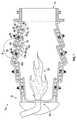
- FIG. 1is a partial sectional view of a combustor and a turbine section of a gas turbine engine
- FIG. 2is a partial sectional view of a shell and a wall panel assembly of the gas turbine engine
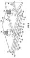
- FIG. 3is a partial sectional view of another configuration of the combustor and the turbine section of the gas turbine engine
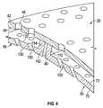
- FIG. 4is a partial sectional view of another configuration of the shell and the wall panel assembly of the gas turbine engine
- FIG. 5is a partial axial sectional view of a first configuration of a wall panel assembly
- FIG. 6is a partial axial sectional view of a second configuration of a wall panel assembly
- FIG. 7is a partial axial sectional view of a third configuration of a wall panel assembly.
- FIG. 8is a partial circumferential sectional view of at least one of the first, second, and third configuration of the wall panel assembly.
- FIG. 1a partial sectional view of a portion of gas turbine engine 10 is shown.
- the portion of the gas turbine engine 10includes at least a portion of a combustor section 12 and a vane 14 of the combustor section 12 or a turbine section that is disposed downstream of the combustor section 12 .
- the combustor section 12includes an annular shell 20 and a wall panel assembly 22 .
- the annular shell 20extends axially and circumferentially between a fuel nozzle assembly 30 and the vane 14 .
- the fuel nozzle assembly 30is configured to mix and ignite compressed air that is delivered to the combustor section 12 with fuel to generate a flame and/or hot combustion gases 32 that are contained within the annular shell 20 and pass through the vane 14 and into the turbine section.
- the annular shell 20may be formed of the plurality of axially and/or circumferentially arranged shell sections that are contiguous or joined together.
- the annular shell 20includes an annular shell inner surface 40 and an annular shell outer surface 42 that is disposed opposite the annular shell inner surface 40 .
- the annular shell inner surface 40 and the outer annular shell surface 42each extend axially and circumferentially between the fuel nozzle assembly 30 and the vane 14 .
- the annular shell 20defines at least one mounting hole 44 and at least one cooling hole 46 .
- the at least one mounting hole 44extends from the annular shell outer surface 42 to the annular shell inner surface 40 .
- the at least one cooling hole 46is spaced apart from the at least one mounting hole 44 .
- the at least one cooling hole 46is disposed substantially parallel to the at least one mounting hole 44 , as shown in FIGS. 1-4 .
- a plurality of cooling holesmay be provided in the annular shell 20 .
- the plurality of cooling holesare disposed about and are axially and circumferentially spaced apart from the at least one mounting hole 44 .
- the wall panel assembly 22is operatively connected to the annular shell 20 .
- the wall panel assembly 22is configured to provide thermal protection for the annular shell 20 from the combustion gases that are contained within the annular shell 20 .
- the wall panel assembly 22includes a first liner panel 50 , a grommet 52 (see FIGS. 5-7 ), a stud 54 , a coating 56 (see FIGS. 5-8 ), and a second liner panel 58 .
- the first liner panel 50includes a first liner panel inner surface 70 , a first liner panel outer surface 72 , a first liner panel first side 74 , and a first liner panel second side 76 .
- the first liner panel inner surface 70is disposed opposite and is radially spaced apart from the first liner panel outer surface 72 .
- the first liner panel inner surface 70 and the first liner panel outer surface 72are each disposed substantially parallel to the annular shell inner surface 40 .
- the first liner panel inner surface 70 and the first liner panel outer surface 72each axially extend between a first liner panel first end 80 and a first liner panel second end 82 that is disposed opposite the first liner panel first end 80 .
- the first liner panel inner surface 70 and the first liner panel outer surface 72each circumferentially extend between the first liner panel first side 74 and the first liner panel second side 76 .
- Cooling airmay enter through the at least one cooling hole 46 and impinge on the first liner panel outer surface 72 .
- the cooling airmay be fed from a region external to the combustor section 12 having a temperature less than the temperature of the combustion gases contained within the combustor section 12 to cool the first liner panel 50 .
- a plurality of cooling pins 90are disposed on the first liner panel outer surface 72 .
- the plurality of cooling pins 90extend from the first liner panel outer surface 72 towards the annular shell inner surface 40 .
- the plurality of cooling pins 90are configured to increase the surface area of the first liner panel 50 to improve heat transfer from the first liner panel 50 .
- the plurality of cooling pins 90are spaced apart from and do not engage the annular shell inner surface 40 by the grommet 52 .
- the grommet 52is disposed on the first liner panel outer surface 72 .
- the grommet 52is configured to space the plurality of cooling pins 90 apart from the annular shell inner surface 40 .
- the grommet 52may engage the first liner panel outer surface 72 and the annular shell inner surface 40 .
- the grommet 52sets a spacing or distance between the first liner panel 50 and the first liner panel outer surface 72 and the annular shell inner surface 40 .
- the stud 54is configured to operatively connect the first liner panel 50 to the annular shell 20 .
- the stud 54extends from the first liner panel outer surface 72 and is received in the at least one mounting hole 44 of the annular shell 20 such that the stud 54 extends completely through the annular shell inner surface 40 and the annular shell outer surface 42 .
- the stud 54may be a fastener, a pin, or the like that is secured to the annular shell by a nut or the like that is disposed on the annular shell outer surface 42 .
- the first liner panel 50is provided with a plurality of liner panel cooling holes 100 .
- the plurality of liner panel cooling holes 100extend from the first liner panel outer surface 72 towards the first liner panel inner surface 70 .
- the plurality of liner panel cooling holes 100are configured to receive the cooling air that enters through the at least one cooling hole 46 to aid in cooling the first liner panel 50 .
- At least one liner panel cooling hole of the plurality of liner panel cooling holes 100is proximately aligned with the at least one cooling hole 46 such that an outlet of the at least one cooling hole 46 directly flows into an inlet of at least one liner panel cooling hole of the plurality of liner panel cooling holes 100 .
- the plurality of liner panel cooling holes 100are disposed at an angle relative to the at least one cooling hole 46 of the annular shell 20 .
- the plurality of liner panel cooling holes 100are disposed in a non-parallel relationship relative to the at least one cooling hole 46 of the annular shell 20 .
- the plurality of liner panel cooling holes 100may be provided in conjunction with the plurality of cooling pins 90 or may be provided as an alternative to the plurality of cooling pins 90 .
- the first liner panel 50includes a first arm 110 and a second arm 112 .
- the first arm 110is disposed proximate the first liner panel first end 80 and extends towards the annular shell inner surface 40 .
- the first arm 110is spaced apart from the annular shell inner surface 40 .
- the second arm 112is disposed proximate the first liner panel second end 82 and extends towards the annular shell inner surface 40 .
- the second arm 112is spaced apart from the annular shell inner surface 40 .
- the grommet 52may be provided and aids in spacing the first arm 110 and the second arm 112 from the shell inner surface 40 .
- the coating 56is applied to the first liner panel 50 .
- the coating 56is disposed on the first liner panel inner surface 70 and/or the first liner panel outer surface 72 .
- the coating 56may be applied to at least one of the first liner panel inner surface 70 and the first liner panel outer surface 72 such that at least one of the first liner panel inner surface 70 and the first liner panel outer surface 72 is coated by the coating 56 and the other of the at least one of the first liner panel inner surface 70 and the first liner panel outer surface 72 is uncoated or not coated by the coating 56 .
- the coating 56is a thermal barrier coating that is configured to provide thermal protection to the first liner panel 50 .
- the combination of the coating 56 and the cooling air that enters through the at least one cooling hole 46 and impinges or flows through the first liner panel 50controls the temperature of the first liner panel 50 and ultimately the annular shell 20 .
- the constraining of the first liner panel 50 with the annular shell 20 by the stud 54 and temperature differences due to the cooling air that impinges or flows through the first liner panel 50may result in high thermal stresses that may lead to thermal mechanical fatigue cracking of at least one of the coating 56 and the first liner panel 50 .
- first liner panel first end 80may be cooler as compared to the first liner panel second end 82 due to the cooling air provided through the at least one cooling hole 46 impinging closer to the first liner panel first end 80 than the first liner panel second end 82 .
- the coating 56is applied to the first liner panel inner surface 70 and/or the first liner panel outer surface 72 such that it has a varying or variable overall thickness in at least one of the axial direction and the circumferential direction of the first liner panel 50 to control the temperature of the first liner panel 50 .
- the overall thickness of the coating 56may be thinner proximate areas of the first liner panel 50 that are disposed proximate the at least one cooling hole 46 of the annular shell 20 and may be thicker proximate areas of the first liner panel 50 that are spaced apart from the at least one cooling hole 46 of the annular shell 20 . Additionally, the overall thickness of the coating 56 may be thicker proximate areas of the first liner panel 50 that are disposed closer to the flame or hot combustion gases and may be thinner proximate areas of the first liner panel 50 that are disposed further from the flame or hot combustion gases.
- the coating 56may have a variable nominal overall thickness distribution to reduce thermal gradients and results in a more isothermal design of the first liner panel 50 . Ultimately, the coating 56 having a variable nominal overall thickness distribution improves service life of the combustor section 12 and the overall gas turbine engine. The coating 56 may also reduce overhaul and repair costs for the gas turbine engine 10 .
- the coating 56includes a first coating 120 and a second coating 122 .
- the first coating 120is disposed on at least one of the first liner panel inner surface 70 and the first liner panel outer surface 72 .
- the first coating 120may be a metallic bond coating to aid in bonding the second coating 122 to at least one of the first coating 120 and the first liner panel inner surface 70 and/or the first liner panel outer surface 72 .
- the second coating 122is disposed on the first coating 120 and may be an applied ceramic-based coating, a thermal barrier coating, a flame sprayed ceramic, or the like.
- a combination of the first coating 120 and the second coating 122defines the overall thickness of the coating 56 .
- the thickness of at least one of the first coating 120 and the second coating 122may be varied axially and/or circumferentially over the first liner panel inner surface 70 and/or the first liner panel outer surface 72 to vary the overall thickness of the coating 56 axially and/or circumferentially over the first liner panel inner surface 70 and/or the first liner panel outer surface 72 .
- the coating 56defines a first overall thickness, t 1 , that is disposed proximate the first liner panel first end 80 , a second overall thickness, t 2 , that is disposed proximate the first liner panel second end 82 , and an overall thickness, t 0 , that extends or is disposed between the first liner panel first end 80 and the first liner panel second end 82 .
- the first overall thickness, t 1may be different from the second overall thickness, t 2 .
- the first overall thickness, t 1may be substantially constant circumferentially in a direction that extends between the first liner panel first side 74 and the first liner panel second side 76 . As shown in FIG. 8 , the first overall thickness, t 1 , may vary circumferentially in a direction that extends between the first liner panel first side 74 and the first liner panel second side 76 .
- the second overall thickness, t 2may be substantially constant circumferentially in a direction that extends between the first liner panel first side 74 and the first liner panel second side 76 . As shown in FIG. 8 , the second overall thickness, t 2 , may vary circumferentially in a direction that extends between the first liner panel first side 74 and the first liner panel second side 76 .
- the overall thickness, t 0of the coating 56 varies between the first liner panel first end 80 and the first liner panel second end 82 according to a ramp function.
- the ramp functionincreases the overall thickness, t 0 , of the coating 56 in the axial direction from the first liner panel first end 80 and the first liner panel second end 82 such that the second overall thickness, t 2 , is greater than the first overall thickness, t 1 .
- the ramp functionincreases the overall thickness, t 0 , of the coating 56 in the circumferential direction from the first liner panel first side 74 and the first liner panel second side 76 .
- the overall thickness, t 0of the coating 56 varies between the first liner panel first end 80 and the first liner panel second end 82 according to a sinusoidal or pseudo-sinusoidal function.
- the sinusoidal or pseudo-sinusoidal functionincreases and decreases the overall thickness, t 0 , of the coating 56 in the axial direction from the first liner panel first end 80 and the first liner panel second end 82 based on a sine or cosine between coating thickness and axial position.
- the sinusoidal or pseudo-sinusoidal functionincreases and decreases the overall thickness, t 0 , of the coating 56 in the circumferential direction from the first liner panel first side 74 and the first liner panel second side 76 based on a sine or cosine relationship between coating thickness and circumferential position.
- the overall thickness, t 0of the coating 56 varies between the first liner panel first end 80 and the first liner panel second end 82 according to an arbitrary or random function.
- the arbitrary or random functionincreases and/or decreases the overall thickness, t 0 , of the coating 56 in the axial direction from the first liner panel first end 80 and the first liner panel second end 82 .
- the arbitrary or random functionincreases and/or decreases the overall thickness, t 0 , of the coating 56 in the circumferential direction from the first liner panel first side 74 and the first liner panel second side 76 .
- the second liner panel 58is operatively connected to the annular shell 20 .
- the second liner panel 58is disposed proximate the first liner panel 50 .
- the second liner panel 58includes a second liner panel inner surface 130 , a second liner panel outer surface 132 , a second liner panel first side 134 , and a second liner panel second side 136 .
- the second liner panel inner surface 130is disposed opposite and is radially spaced apart from the second liner panel outer surface 132 .
- the second liner panel inner surface 130 and the second liner panel outer surface 132are each disposed substantially parallel to the annular shell inner surface 40 .
- the second liner panel inner surface 130 and the second liner panel outer surface 132each axially extend between a second liner panel first end 140 and a second liner panel second end 142 that is disposed opposite the second liner panel first end 140 .
- the second liner panel inner surface 130 and the second liner panel outer surface 132each circumferentially extend between the second liner panel first side 134 and the second liner panel second side 136 .
- the second liner panel 58has a substantially similar configuration to the first liner panel 50 and may also include the coating 56 that is disposed on the second liner panel inner surface 130 .
- the second liner panel second end 142axially overlaps the first liner panel first end 80 .
- the second liner panel second end 142is radially spaced apart from the first liner panel first end 80 and defines a gap 150 therebetween.
- the cooling air that enters through the at least one cooling hole 46may flow through the gap 150 and cool at least one of the second liner panel second end 142 and the first liner panel first end 80 .
- the second liner panel 58includes a first arm 152 and a second arm 154 .
- the first arm 152is disposed proximate the second liner panel first end 140 and extends towards the annular shell inner surface 40 .
- the first arm 152is configured to engage the annular shell inner surface 40 .
- the second arm 154is disposed proximate the second liner panel second end 142 and extends towards the annular shell inner surface 40 .
- the second arm 154is configured to engage the annular shell inner surface 40 .
- the second liner panel second end 142abuts the first liner panel first end 80 such that the second arm 154 of the second liner panel 58 abuts the first arm 110 of the first liner panel 50 .
- attachmentshall be interpreted to mean that a structural component or element is in some manner connected to or contacts another element, either directly or indirectly through at least one intervening structural element, or is integrally formed with the other structural element.
Landscapes
- Engineering & Computer Science (AREA)
- Chemical & Material Sciences (AREA)
- Combustion & Propulsion (AREA)
- Mechanical Engineering (AREA)
- General Engineering & Computer Science (AREA)
- Turbine Rotor Nozzle Sealing (AREA)
Abstract
Description
Claims (12)
Priority Applications (3)
| Application Number | Priority Date | Filing Date | Title |
|---|---|---|---|
| US15/266,036US10386067B2 (en) | 2016-09-15 | 2016-09-15 | Wall panel assembly for a gas turbine engine |
| EP22187045.4AEP4098945B1 (en) | 2016-09-15 | 2017-09-14 | Wall panel assembly for a gas turbine engine |
| EP17191190.2AEP3306195B1 (en) | 2016-09-15 | 2017-09-14 | Wall panel assembly for a gas turbine engine |
Applications Claiming Priority (1)
| Application Number | Priority Date | Filing Date | Title |
|---|---|---|---|
| US15/266,036US10386067B2 (en) | 2016-09-15 | 2016-09-15 | Wall panel assembly for a gas turbine engine |
Publications (2)
| Publication Number | Publication Date |
|---|---|
| US20180073737A1 US20180073737A1 (en) | 2018-03-15 |
| US10386067B2true US10386067B2 (en) | 2019-08-20 |
Family
ID=59895147
Family Applications (1)
| Application Number | Title | Priority Date | Filing Date |
|---|---|---|---|
| US15/266,036Active2037-06-13US10386067B2 (en) | 2016-09-15 | 2016-09-15 | Wall panel assembly for a gas turbine engine |
Country Status (2)
| Country | Link |
|---|---|
| US (1) | US10386067B2 (en) |
| EP (2) | EP3306195B1 (en) |
Families Citing this family (3)
| Publication number | Priority date | Publication date | Assignee | Title |
|---|---|---|---|---|
| US10995955B2 (en) | 2018-08-01 | 2021-05-04 | Raytheon Technologies Corporation | Combustor panel |
| US11047575B2 (en)* | 2019-04-15 | 2021-06-29 | Raytheon Technologies Corporation | Combustor heat shield panel |
| JP2024043164A (en)* | 2022-09-16 | 2024-03-29 | 三菱重工航空エンジン株式会社 | heat exchange bulkhead |
Citations (79)
| Publication number | Priority date | Publication date | Assignee | Title |
|---|---|---|---|---|
| US5528904A (en)* | 1994-02-28 | 1996-06-25 | Jones; Charles R. | Coated hot gas duct liner |
| US5630314A (en)* | 1992-09-10 | 1997-05-20 | Hitachi, Ltd. | Thermal stress relaxation type ceramic coated heat-resistant element |
| US5817372A (en)* | 1997-09-23 | 1998-10-06 | General Electric Co. | Process for depositing a bond coat for a thermal barrier coating system |
| US6096381A (en)* | 1997-10-27 | 2000-08-01 | General Electric Company | Process for densifying and promoting inter-particle bonding of a bond coat for a thermal barrier coating |
| US6136453A (en)* | 1998-11-24 | 2000-10-24 | General Electric Company | Roughened bond coat for a thermal barrier coating system and method for producing |
| US6207295B1 (en)* | 1999-07-13 | 2001-03-27 | General Electric Company | Article with tailorable high temperature coating |
| US20010017034A1 (en)* | 2000-02-29 | 2001-08-30 | Spooner Michael P. | Wall elements for gas turbine engine combustors |
| US6408628B1 (en)* | 1999-11-06 | 2002-06-25 | Rolls-Royce Plc | Wall elements for gas turbine engine combustors |
| US20020102360A1 (en)* | 2001-01-30 | 2002-08-01 | Siemens Westinghouse Power Corporation | Thermal barrier coating applied with cold spray technique |
| US6438958B1 (en)* | 2000-02-28 | 2002-08-27 | General Electric Company | Apparatus for reducing heat load in combustor panels |
| US20020124572A1 (en)* | 2001-03-12 | 2002-09-12 | Anthony Pidcock | Combustion apparatus |
| US20030145604A1 (en)* | 2002-01-15 | 2003-08-07 | Anthony Pidcock | Double wall combustor tile arrangement |
| US20040126229A1 (en)* | 2002-12-31 | 2004-07-01 | General Electric Company | High temperature turbine nozzle for temperature reduction by optical reflection and process for manufacturing |
| US20040123598A1 (en)* | 2002-12-31 | 2004-07-01 | General Electric Company | High temperature combustor wall for temperature reduction by optical reflection and process for manufacturing |
| US20040131877A1 (en)* | 1999-05-03 | 2004-07-08 | Hasz Wayne Charles | Article having turbulation and method of providing turbulation on an article |
| US20040166355A1 (en)* | 2003-02-24 | 2004-08-26 | General Electric Company | Coating and coating process incorporating raised surface features for an air-cooled surface |
| US20040258946A1 (en)* | 2001-07-06 | 2004-12-23 | Allen William P. | Reflective coatings to reduce radiation heat transfer |
| US20050034399A1 (en)* | 2002-01-15 | 2005-02-17 | Rolls-Royce Plc | Double wall combustor tile arrangement |
| US20050050896A1 (en)* | 2003-09-10 | 2005-03-10 | Mcmasters Marie Ann | Thick coated combustor liner |
| US20050086940A1 (en)* | 2003-10-23 | 2005-04-28 | Coughlan Joseph D.Iii | Combustor |
| US20050282020A1 (en)* | 2004-06-18 | 2005-12-22 | General Electric Company | Smooth outer coating for combustor components and coating method therefor |
| US20060016191A1 (en)* | 2004-07-23 | 2006-01-26 | Honeywell International Inc. | Combined effusion and thick TBC cooling method |
| US20060083937A1 (en)* | 2004-10-18 | 2006-04-20 | United Technologies Corporation | Thermal barrier coating |
| US20070036997A1 (en)* | 2005-06-30 | 2007-02-15 | Honeywell International, Inc. | Thermal barrier coating resistant to penetration by environmental contaminants |
| US20070193216A1 (en)* | 2006-01-25 | 2007-08-23 | Woolford James R | Wall elements for gas turbine engine combustors |
| US20070207328A1 (en)* | 2006-03-01 | 2007-09-06 | United Technologies Corporation | High density thermal barrier coating |
| US20080085395A1 (en)* | 2005-04-07 | 2008-04-10 | Alstom Technology Ltd | Method for repairing or renewing cooling holes of a coated component of a gas turbine |
| US20080134683A1 (en)* | 2006-09-01 | 2008-06-12 | Rolls-Royce Plc | Wall elements for gas turbine engine components |
| US20080145211A1 (en)* | 2006-12-19 | 2008-06-19 | Rolls-Royce Plc | Wall elements for gas turbine engine components |
| US20080292859A1 (en)* | 2007-05-07 | 2008-11-27 | Siemens Aktiengesellschaft | Ceramic powder, ceramic layer and layer system having gadolinium/mixed crystal pyrochlore phases and oxides |
| US7479328B2 (en)* | 2003-07-25 | 2009-01-20 | Rolls-Royce Deutschland Ltd & Co Kg | Shroud segment for a turbomachine |
| US20090142548A1 (en)* | 2007-10-18 | 2009-06-04 | David Bruce Patterson | Air cooled gas turbine components and methods of manufacturing and repairing the same |
| US20100011775A1 (en)* | 2008-07-17 | 2010-01-21 | Rolls-Royce Plc | Combustion apparatus |
| US20100015401A1 (en)* | 2008-05-26 | 2010-01-21 | Andrea Bolz | Ceramic thermal barrier coating system with two ceramic layers |
| US20100071382A1 (en)* | 2008-09-25 | 2010-03-25 | Siemens Energy, Inc. | Gas Turbine Transition Duct |
| US20100095678A1 (en)* | 2008-10-22 | 2010-04-22 | Eduardo Hawie | Heat Shield Sealing for Gas Turbine Engine Combustor |
| US20100162715A1 (en)* | 2008-12-31 | 2010-07-01 | General Electric Company | Method and system for enhancing heat transfer of turbine engine components |
| US20110038710A1 (en)* | 2009-08-14 | 2011-02-17 | Alstom Technologies Ltd. | Application of Dense Vertically Cracked and Porous Thermal Barrier Coating to a Gas Turbine Component |
| US7919151B2 (en)* | 2006-12-14 | 2011-04-05 | General Electric Company | Methods of preparing wetting-resistant surfaces and articles incorporating the same |
| US20110151219A1 (en)* | 2009-12-21 | 2011-06-23 | Bangalore Nagaraj | Coating Systems for Protection of Substrates Exposed to Hot and Harsh Environments and Coated Articles |
| US20120034471A1 (en)* | 2010-08-09 | 2012-02-09 | Honeywell International Inc. | Thermal barrier systems including yttrium gradient layers and methods for the formation thereof |
| US20120102959A1 (en)* | 2010-10-29 | 2012-05-03 | John Howard Starkweather | Substrate with shaped cooling holes and methods of manufacture |
| US20120255308A1 (en)* | 2011-04-06 | 2012-10-11 | Rolls-Royce Plc | Cooled double walled article |
| US20130014510A1 (en)* | 2011-07-15 | 2013-01-17 | United Technologies Corporation | Coated gas turbine components |
| US20130031904A1 (en)* | 2011-08-02 | 2013-02-07 | Rolls-Royce Plc | Combustion chamber |
| US20130047618A1 (en)* | 2011-08-26 | 2013-02-28 | Rolls-Royce Plc | Wall elements for gas turbine engines |
| US20130055722A1 (en)* | 2011-09-06 | 2013-03-07 | Jeffrey Verhiel | Pin fin arrangement for heat shield of gas turbine engine |
| US20130091847A1 (en)* | 2011-10-13 | 2013-04-18 | General Electric Company | Combustor liner |
| US20130209232A1 (en)* | 2012-02-15 | 2013-08-15 | Jinquan Xu | Multi-lobed cooling holes in gas turbine engine components having thermal barrier coatings |
| US20130255269A1 (en)* | 2012-04-02 | 2013-10-03 | Crisen McKenzie | Combustor having a beveled grommet |
| US20130269354A1 (en)* | 2010-10-29 | 2013-10-17 | General Electric Company | Substrate with Shaped Cooling Holes and Methods of Manufacture |
| US20140086810A1 (en)* | 2012-09-26 | 2014-03-27 | General Electric Company | System and method for employing catalytic reactor coatings |
| US20140147251A1 (en)* | 2012-11-23 | 2014-05-29 | Alstom Technology Ltd | Insert element for closing an opening inside a wall of a hot gas path component of a gas turbine and method for enhancing operational behaviour of a gas turbine |
| US20140161585A1 (en)* | 2012-12-10 | 2014-06-12 | General Electric Company | Turbo-machine component and method |
| US20140250894A1 (en)* | 2013-03-05 | 2014-09-11 | Rolls-Royce North American Technologies, Inc. | Dual-wall impingement, convection, effusion (dice) combustor tile |
| US20140290258A1 (en)* | 2012-12-27 | 2014-10-02 | Rolls-Royce Deutschaland Ltd. & Co KG | Method for the arrangement of impingement cooling holes and effusion holes in a combustion chamber wall of a gas turbine |
| US20140360196A1 (en)* | 2013-03-15 | 2014-12-11 | Rolls-Royce Corporation | Shell and tiled liner arrangement for a combustor |
| WO2015047472A2 (en) | 2013-06-14 | 2015-04-02 | United Technologies Corporation | Conductive panel surface cooling augmentation for gas turbine engine combustor |
| US20150300645A1 (en)* | 2013-09-06 | 2015-10-22 | Rolls-Royce Plc | Combustion chamber arrangement |
| US20150377069A1 (en)* | 2014-06-30 | 2015-12-31 | Rolls-Royce Corporation | Coating for isolating metallic components from composite components |
| US20160097325A1 (en)* | 2014-10-02 | 2016-04-07 | Rolls-Royce Plc | Cooled component |
| US20160097285A1 (en)* | 2014-10-06 | 2016-04-07 | Rolls-Royce Plc | Cooled component |
| US20160109128A1 (en)* | 2013-06-14 | 2016-04-21 | United Technologies Corporation | Gas turbine engine wave geometry combustor liner panel |
| US20160195272A1 (en)* | 2014-12-16 | 2016-07-07 | United Technologies Corporation | Methods for coating gas turbine engine components |
| US20160209033A1 (en)* | 2015-01-20 | 2016-07-21 | United Technologies Corporation | Combustor dilution hole passive heat transfer control |
| US20160252250A1 (en)* | 2015-02-26 | 2016-09-01 | General Electric Company | Internal thermal coatings for engine components |
| US20160265367A1 (en)* | 2014-12-22 | 2016-09-15 | General Electric Company | Environmental barrier coating with abradable coating for ceramic matrix composites |
| US20160273391A1 (en)* | 2013-11-04 | 2016-09-22 | United Technologies Corporation | Coated cooling passage |
| US20160298467A1 (en)* | 2013-11-18 | 2016-10-13 | United Technologies Corporation | Article having variable coating |
| US20170009987A1 (en)* | 2014-02-03 | 2017-01-12 | United Technologies Corporation | Stepped heat shield for a turbine engine combustor |
| US20170081753A1 (en)* | 2015-09-21 | 2017-03-23 | General Electric Company | Thermal barrier coating system and processes for forming a thermal barrier coating system |
| US20170108219A1 (en)* | 2015-10-16 | 2017-04-20 | Rolls-Royce Plc | Combustor for a gas turbine engine |
| US20170107833A1 (en)* | 2014-06-25 | 2017-04-20 | Siemens Aktiengesellschaft | Gas turbine engine with a transition duct and corresponding method of manufacturing a transition duct |
| US20170176005A1 (en)* | 2015-12-17 | 2017-06-22 | Rolls-Royce Plc | Combustion chamber |
| US20170211811A1 (en)* | 2016-01-21 | 2017-07-27 | Siemens Energy, Inc. | Transition duct system with arcuate ceramic liner for delivering hot-temperature gases in a combustion turbine engine |
| US20170241643A1 (en)* | 2016-02-24 | 2017-08-24 | Rolls-Royce Plc | Combustion chamber |
| US20170276356A1 (en)* | 2016-03-22 | 2017-09-28 | Rolls-Royce Plc | Combustion chamber assembly |
| US20170356653A1 (en)* | 2016-06-10 | 2017-12-14 | Rolls-Royce Plc | Combustion chamber |
| US20180038593A1 (en)* | 2016-08-04 | 2018-02-08 | United Technologies Corporation | Combustor panel for gas turbine engine |
- 2016
- 2016-09-15USUS15/266,036patent/US10386067B2/enactiveActive
- 2017
- 2017-09-14EPEP17191190.2Apatent/EP3306195B1/enactiveActive
- 2017-09-14EPEP22187045.4Apatent/EP4098945B1/enactiveActive
Patent Citations (79)
| Publication number | Priority date | Publication date | Assignee | Title |
|---|---|---|---|---|
| US5630314A (en)* | 1992-09-10 | 1997-05-20 | Hitachi, Ltd. | Thermal stress relaxation type ceramic coated heat-resistant element |
| US5528904A (en)* | 1994-02-28 | 1996-06-25 | Jones; Charles R. | Coated hot gas duct liner |
| US5817372A (en)* | 1997-09-23 | 1998-10-06 | General Electric Co. | Process for depositing a bond coat for a thermal barrier coating system |
| US6096381A (en)* | 1997-10-27 | 2000-08-01 | General Electric Company | Process for densifying and promoting inter-particle bonding of a bond coat for a thermal barrier coating |
| US6136453A (en)* | 1998-11-24 | 2000-10-24 | General Electric Company | Roughened bond coat for a thermal barrier coating system and method for producing |
| US20040131877A1 (en)* | 1999-05-03 | 2004-07-08 | Hasz Wayne Charles | Article having turbulation and method of providing turbulation on an article |
| US6207295B1 (en)* | 1999-07-13 | 2001-03-27 | General Electric Company | Article with tailorable high temperature coating |
| US6408628B1 (en)* | 1999-11-06 | 2002-06-25 | Rolls-Royce Plc | Wall elements for gas turbine engine combustors |
| US6438958B1 (en)* | 2000-02-28 | 2002-08-27 | General Electric Company | Apparatus for reducing heat load in combustor panels |
| US20010017034A1 (en)* | 2000-02-29 | 2001-08-30 | Spooner Michael P. | Wall elements for gas turbine engine combustors |
| US20020102360A1 (en)* | 2001-01-30 | 2002-08-01 | Siemens Westinghouse Power Corporation | Thermal barrier coating applied with cold spray technique |
| US20020124572A1 (en)* | 2001-03-12 | 2002-09-12 | Anthony Pidcock | Combustion apparatus |
| US20040258946A1 (en)* | 2001-07-06 | 2004-12-23 | Allen William P. | Reflective coatings to reduce radiation heat transfer |
| US20030145604A1 (en)* | 2002-01-15 | 2003-08-07 | Anthony Pidcock | Double wall combustor tile arrangement |
| US20050034399A1 (en)* | 2002-01-15 | 2005-02-17 | Rolls-Royce Plc | Double wall combustor tile arrangement |
| US20040126229A1 (en)* | 2002-12-31 | 2004-07-01 | General Electric Company | High temperature turbine nozzle for temperature reduction by optical reflection and process for manufacturing |
| US20040123598A1 (en)* | 2002-12-31 | 2004-07-01 | General Electric Company | High temperature combustor wall for temperature reduction by optical reflection and process for manufacturing |
| US20040166355A1 (en)* | 2003-02-24 | 2004-08-26 | General Electric Company | Coating and coating process incorporating raised surface features for an air-cooled surface |
| US7479328B2 (en)* | 2003-07-25 | 2009-01-20 | Rolls-Royce Deutschland Ltd & Co Kg | Shroud segment for a turbomachine |
| US20050050896A1 (en)* | 2003-09-10 | 2005-03-10 | Mcmasters Marie Ann | Thick coated combustor liner |
| US20050086940A1 (en)* | 2003-10-23 | 2005-04-28 | Coughlan Joseph D.Iii | Combustor |
| US20050282020A1 (en)* | 2004-06-18 | 2005-12-22 | General Electric Company | Smooth outer coating for combustor components and coating method therefor |
| US20060016191A1 (en)* | 2004-07-23 | 2006-01-26 | Honeywell International Inc. | Combined effusion and thick TBC cooling method |
| US20060083937A1 (en)* | 2004-10-18 | 2006-04-20 | United Technologies Corporation | Thermal barrier coating |
| US20080085395A1 (en)* | 2005-04-07 | 2008-04-10 | Alstom Technology Ltd | Method for repairing or renewing cooling holes of a coated component of a gas turbine |
| US20070036997A1 (en)* | 2005-06-30 | 2007-02-15 | Honeywell International, Inc. | Thermal barrier coating resistant to penetration by environmental contaminants |
| US20070193216A1 (en)* | 2006-01-25 | 2007-08-23 | Woolford James R | Wall elements for gas turbine engine combustors |
| US20070207328A1 (en)* | 2006-03-01 | 2007-09-06 | United Technologies Corporation | High density thermal barrier coating |
| US20080134683A1 (en)* | 2006-09-01 | 2008-06-12 | Rolls-Royce Plc | Wall elements for gas turbine engine components |
| US7919151B2 (en)* | 2006-12-14 | 2011-04-05 | General Electric Company | Methods of preparing wetting-resistant surfaces and articles incorporating the same |
| US20080145211A1 (en)* | 2006-12-19 | 2008-06-19 | Rolls-Royce Plc | Wall elements for gas turbine engine components |
| US20080292859A1 (en)* | 2007-05-07 | 2008-11-27 | Siemens Aktiengesellschaft | Ceramic powder, ceramic layer and layer system having gadolinium/mixed crystal pyrochlore phases and oxides |
| US20090142548A1 (en)* | 2007-10-18 | 2009-06-04 | David Bruce Patterson | Air cooled gas turbine components and methods of manufacturing and repairing the same |
| US20100015401A1 (en)* | 2008-05-26 | 2010-01-21 | Andrea Bolz | Ceramic thermal barrier coating system with two ceramic layers |
| US20100011775A1 (en)* | 2008-07-17 | 2010-01-21 | Rolls-Royce Plc | Combustion apparatus |
| US20100071382A1 (en)* | 2008-09-25 | 2010-03-25 | Siemens Energy, Inc. | Gas Turbine Transition Duct |
| US20100095678A1 (en)* | 2008-10-22 | 2010-04-22 | Eduardo Hawie | Heat Shield Sealing for Gas Turbine Engine Combustor |
| US20100162715A1 (en)* | 2008-12-31 | 2010-07-01 | General Electric Company | Method and system for enhancing heat transfer of turbine engine components |
| US20110038710A1 (en)* | 2009-08-14 | 2011-02-17 | Alstom Technologies Ltd. | Application of Dense Vertically Cracked and Porous Thermal Barrier Coating to a Gas Turbine Component |
| US20110151219A1 (en)* | 2009-12-21 | 2011-06-23 | Bangalore Nagaraj | Coating Systems for Protection of Substrates Exposed to Hot and Harsh Environments and Coated Articles |
| US20120034471A1 (en)* | 2010-08-09 | 2012-02-09 | Honeywell International Inc. | Thermal barrier systems including yttrium gradient layers and methods for the formation thereof |
| US20130269354A1 (en)* | 2010-10-29 | 2013-10-17 | General Electric Company | Substrate with Shaped Cooling Holes and Methods of Manufacture |
| US20120102959A1 (en)* | 2010-10-29 | 2012-05-03 | John Howard Starkweather | Substrate with shaped cooling holes and methods of manufacture |
| US20120255308A1 (en)* | 2011-04-06 | 2012-10-11 | Rolls-Royce Plc | Cooled double walled article |
| US20130014510A1 (en)* | 2011-07-15 | 2013-01-17 | United Technologies Corporation | Coated gas turbine components |
| US20130031904A1 (en)* | 2011-08-02 | 2013-02-07 | Rolls-Royce Plc | Combustion chamber |
| US20130047618A1 (en)* | 2011-08-26 | 2013-02-28 | Rolls-Royce Plc | Wall elements for gas turbine engines |
| US20130055722A1 (en)* | 2011-09-06 | 2013-03-07 | Jeffrey Verhiel | Pin fin arrangement for heat shield of gas turbine engine |
| US20130091847A1 (en)* | 2011-10-13 | 2013-04-18 | General Electric Company | Combustor liner |
| US20130209232A1 (en)* | 2012-02-15 | 2013-08-15 | Jinquan Xu | Multi-lobed cooling holes in gas turbine engine components having thermal barrier coatings |
| US20130255269A1 (en)* | 2012-04-02 | 2013-10-03 | Crisen McKenzie | Combustor having a beveled grommet |
| US20140086810A1 (en)* | 2012-09-26 | 2014-03-27 | General Electric Company | System and method for employing catalytic reactor coatings |
| US20140147251A1 (en)* | 2012-11-23 | 2014-05-29 | Alstom Technology Ltd | Insert element for closing an opening inside a wall of a hot gas path component of a gas turbine and method for enhancing operational behaviour of a gas turbine |
| US20140161585A1 (en)* | 2012-12-10 | 2014-06-12 | General Electric Company | Turbo-machine component and method |
| US20140290258A1 (en)* | 2012-12-27 | 2014-10-02 | Rolls-Royce Deutschaland Ltd. & Co KG | Method for the arrangement of impingement cooling holes and effusion holes in a combustion chamber wall of a gas turbine |
| US20140250894A1 (en)* | 2013-03-05 | 2014-09-11 | Rolls-Royce North American Technologies, Inc. | Dual-wall impingement, convection, effusion (dice) combustor tile |
| US20140360196A1 (en)* | 2013-03-15 | 2014-12-11 | Rolls-Royce Corporation | Shell and tiled liner arrangement for a combustor |
| WO2015047472A2 (en) | 2013-06-14 | 2015-04-02 | United Technologies Corporation | Conductive panel surface cooling augmentation for gas turbine engine combustor |
| US20160109128A1 (en)* | 2013-06-14 | 2016-04-21 | United Technologies Corporation | Gas turbine engine wave geometry combustor liner panel |
| US20150300645A1 (en)* | 2013-09-06 | 2015-10-22 | Rolls-Royce Plc | Combustion chamber arrangement |
| US20160273391A1 (en)* | 2013-11-04 | 2016-09-22 | United Technologies Corporation | Coated cooling passage |
| US20160298467A1 (en)* | 2013-11-18 | 2016-10-13 | United Technologies Corporation | Article having variable coating |
| US20170009987A1 (en)* | 2014-02-03 | 2017-01-12 | United Technologies Corporation | Stepped heat shield for a turbine engine combustor |
| US20170107833A1 (en)* | 2014-06-25 | 2017-04-20 | Siemens Aktiengesellschaft | Gas turbine engine with a transition duct and corresponding method of manufacturing a transition duct |
| US20150377069A1 (en)* | 2014-06-30 | 2015-12-31 | Rolls-Royce Corporation | Coating for isolating metallic components from composite components |
| US20160097325A1 (en)* | 2014-10-02 | 2016-04-07 | Rolls-Royce Plc | Cooled component |
| US20160097285A1 (en)* | 2014-10-06 | 2016-04-07 | Rolls-Royce Plc | Cooled component |
| US20160195272A1 (en)* | 2014-12-16 | 2016-07-07 | United Technologies Corporation | Methods for coating gas turbine engine components |
| US20160265367A1 (en)* | 2014-12-22 | 2016-09-15 | General Electric Company | Environmental barrier coating with abradable coating for ceramic matrix composites |
| US20160209033A1 (en)* | 2015-01-20 | 2016-07-21 | United Technologies Corporation | Combustor dilution hole passive heat transfer control |
| US20160252250A1 (en)* | 2015-02-26 | 2016-09-01 | General Electric Company | Internal thermal coatings for engine components |
| US20170081753A1 (en)* | 2015-09-21 | 2017-03-23 | General Electric Company | Thermal barrier coating system and processes for forming a thermal barrier coating system |
| US20170108219A1 (en)* | 2015-10-16 | 2017-04-20 | Rolls-Royce Plc | Combustor for a gas turbine engine |
| US20170176005A1 (en)* | 2015-12-17 | 2017-06-22 | Rolls-Royce Plc | Combustion chamber |
| US20170211811A1 (en)* | 2016-01-21 | 2017-07-27 | Siemens Energy, Inc. | Transition duct system with arcuate ceramic liner for delivering hot-temperature gases in a combustion turbine engine |
| US20170241643A1 (en)* | 2016-02-24 | 2017-08-24 | Rolls-Royce Plc | Combustion chamber |
| US20170276356A1 (en)* | 2016-03-22 | 2017-09-28 | Rolls-Royce Plc | Combustion chamber assembly |
| US20170356653A1 (en)* | 2016-06-10 | 2017-12-14 | Rolls-Royce Plc | Combustion chamber |
| US20180038593A1 (en)* | 2016-08-04 | 2018-02-08 | United Technologies Corporation | Combustor panel for gas turbine engine |
Non-Patent Citations (1)
| Title |
|---|
| European Search Report for EP Application No. 17191190.2 dated Mar. 22, 2018; 8 pages. |
Also Published As
| Publication number | Publication date |
|---|---|
| EP3306195A2 (en) | 2018-04-11 |
| US20180073737A1 (en) | 2018-03-15 |
| EP4098945A1 (en) | 2022-12-07 |
| EP3306195A3 (en) | 2018-04-25 |
| EP4098945B1 (en) | 2025-09-03 |
| EP3306195B1 (en) | 2023-09-06 |
Similar Documents
| Publication | Publication Date | Title |
|---|---|---|
| US7845174B2 (en) | Combustor liner with improved heat shield retention | |
| US8695322B2 (en) | Thermally decoupled can-annular transition piece | |
| US8256224B2 (en) | Combustion apparatus | |
| US7752851B2 (en) | Fastening a combustion chamber inside its casing | |
| EP1811229B1 (en) | Fuel injector nozzles for gas turbine engines | |
| US8424312B2 (en) | Exhaust system for gas turbine | |
| US9052111B2 (en) | Turbine engine combustor wall with non-uniform distribution of effusion apertures | |
| EP2964950B1 (en) | Gas turbine engine with flexible bellows igniter seal assembly | |
| US8448416B2 (en) | Combustor liner | |
| EP4098945B1 (en) | Wall panel assembly for a gas turbine engine | |
| US9670791B2 (en) | Flexible finger seal for sealing a gap between turbine engine components | |
| US20180112875A1 (en) | Combustor assembly with air shield for a radial fuel injector | |
| US10684014B2 (en) | Combustor panel for gas turbine engine | |
| US10408456B2 (en) | Combustion chamber assembly | |
| US20170363295A1 (en) | Small exit duct for a reverse flow combustor with integrated cooling elements | |
| US10174946B2 (en) | Nozzle guide for a combustor of a gas turbine engine | |
| US20180087776A1 (en) | Mounting assembly for gas turbine engine fluid conduit | |
| US12422141B2 (en) | Combustor of gas turbine including a fixture that attaches a liner to an outer wall having a cooling air passage | |
| US20230130521A1 (en) | Combustion chamber having a ceramic heat shield and seal | |
| JP7727755B2 (en) | Gas turbine combustor |
Legal Events
| Date | Code | Title | Description |
|---|---|---|---|
| AS | Assignment | Owner name:UNITED TECHNOLOGIES CORPORATION, CONNECTICUT Free format text:ASSIGNMENT OF ASSIGNORS INTEREST;ASSIGNORS:QUACH, SAN;ELLIOTT, SCOTT A.;SONNTAG, ROBERT M.;AND OTHERS;SIGNING DATES FROM 20160831 TO 20160909;REEL/FRAME:039754/0692 | |
| AS | Assignment | Owner name:UNITED TECHNOLOGIES CORPORATION, CONNECTICUT Free format text:CORRECTIVE ASSIGNMENT TO CORRECT THE EIGHTH ASSIGNOR'S NAME PREVIOUSLY RECORDED AT REEL: 039754 FRAME: 0692. ASSIGNOR(S) HEREBY CONFIRMS THE ASSIGNMENT;ASSIGNORS:QUACH, SAN;ELLIOTT, SCOTT A.;SONNTAG, ROBERT M.;AND OTHERS;SIGNING DATES FROM 20160831 TO 20160909;REEL/FRAME:040503/0122 | |
| STPP | Information on status: patent application and granting procedure in general | Free format text:RESPONSE TO NON-FINAL OFFICE ACTION ENTERED AND FORWARDED TO EXAMINER | |
| STPP | Information on status: patent application and granting procedure in general | Free format text:NOTICE OF ALLOWANCE MAILED -- APPLICATION RECEIVED IN OFFICE OF PUBLICATIONS | |
| STPP | Information on status: patent application and granting procedure in general | Free format text:PUBLICATIONS -- ISSUE FEE PAYMENT VERIFIED | |
| STCF | Information on status: patent grant | Free format text:PATENTED CASE | |
| AS | Assignment | Owner name:RAYTHEON TECHNOLOGIES CORPORATION, MASSACHUSETTS Free format text:CHANGE OF NAME;ASSIGNOR:UNITED TECHNOLOGIES CORPORATION;REEL/FRAME:054062/0001 Effective date:20200403 | |
| AS | Assignment | Owner name:RAYTHEON TECHNOLOGIES CORPORATION, CONNECTICUT Free format text:CORRECTIVE ASSIGNMENT TO CORRECT THE AND REMOVE PATENT APPLICATION NUMBER 11886281 AND ADD PATENT APPLICATION NUMBER 14846874. TO CORRECT THE RECEIVING PARTY ADDRESS PREVIOUSLY RECORDED AT REEL: 054062 FRAME: 0001. ASSIGNOR(S) HEREBY CONFIRMS THE CHANGE OF ADDRESS;ASSIGNOR:UNITED TECHNOLOGIES CORPORATION;REEL/FRAME:055659/0001 Effective date:20200403 | |
| MAFP | Maintenance fee payment | Free format text:PAYMENT OF MAINTENANCE FEE, 4TH YEAR, LARGE ENTITY (ORIGINAL EVENT CODE: M1551); ENTITY STATUS OF PATENT OWNER: LARGE ENTITY Year of fee payment:4 | |
| AS | Assignment | Owner name:RTX CORPORATION, CONNECTICUT Free format text:CHANGE OF NAME;ASSIGNOR:RAYTHEON TECHNOLOGIES CORPORATION;REEL/FRAME:064714/0001 Effective date:20230714 |