US10385257B2 - Gas diverter for well and reservoir stimulation - Google Patents
Gas diverter for well and reservoir stimulationDownload PDFInfo
- Publication number
- US10385257B2 US10385257B2US15/870,677US201815870677AUS10385257B2US 10385257 B2US10385257 B2US 10385257B2US 201815870677 AUS201815870677 AUS 201815870677AUS 10385257 B2US10385257 B2US 10385257B2
- Authority
- US
- United States
- Prior art keywords
- gas
- subterranean formation
- pressurized fluid
- fluid diversion
- fractures
- Prior art date
- Legal status (The legal status is an assumption and is not a legal conclusion. Google has not performed a legal analysis and makes no representation as to the accuracy of the status listed.)
- Expired - Fee Related
Links
- 230000000638stimulationEffects0.000titleclaimsdescription44
- 230000015572biosynthetic processEffects0.000claimsabstractdescription414
- 238000000034methodMethods0.000claimsabstractdescription239
- 239000007789gasSubstances0.000claimsdescription550
- 239000007788liquidSubstances0.000claimsdescription443
- 239000012530fluidSubstances0.000claimsdescription208
- 239000011148porous materialSubstances0.000claimsdescription182
- 239000003795chemical substances by applicationSubstances0.000claimsdescription157
- 238000002347injectionMethods0.000claimsdescription124
- 239000007924injectionSubstances0.000claimsdescription124
- 239000000203mixtureSubstances0.000claimsdescription114
- -1polytetrafluoroethylenePolymers0.000claimsdescription92
- 229930195733hydrocarbonNatural products0.000claimsdescription86
- 150000002430hydrocarbonsChemical class0.000claimsdescription86
- 239000000126substanceSubstances0.000claimsdescription40
- 239000004215Carbon black (E152)Substances0.000claimsdescription35
- 238000004519manufacturing processMethods0.000claimsdescription33
- CURLTUGMZLYLDI-UHFFFAOYSA-NCarbon dioxideChemical compoundO=C=OCURLTUGMZLYLDI-UHFFFAOYSA-N0.000claimsdescription28
- ATUOYWHBWRKTHZ-UHFFFAOYSA-NPropaneChemical compoundCCCATUOYWHBWRKTHZ-UHFFFAOYSA-N0.000claimsdescription24
- IJGRMHOSHXDMSA-UHFFFAOYSA-NAtomic nitrogenChemical compoundN#NIJGRMHOSHXDMSA-UHFFFAOYSA-N0.000claimsdescription22
- 239000007787solidSubstances0.000claimsdescription20
- VNWKTOKETHGBQD-UHFFFAOYSA-NmethaneChemical compoundCVNWKTOKETHGBQD-UHFFFAOYSA-N0.000claimsdescription18
- 239000000463materialSubstances0.000claimsdescription16
- 229920002732PolyanhydridePolymers0.000claimsdescription15
- 229920000642polymerPolymers0.000claimsdescription15
- 239000001569carbon dioxideSubstances0.000claimsdescription14
- 229910002092carbon dioxideInorganic materials0.000claimsdescription14
- 239000000919ceramicSubstances0.000claimsdescription12
- 239000000499gelSubstances0.000claimsdescription12
- 239000001294propaneSubstances0.000claimsdescription11
- 239000011324beadSubstances0.000claimsdescription10
- 229920006237degradable polymerPolymers0.000claimsdescription10
- 229910052757nitrogenInorganic materials0.000claimsdescription10
- 230000004888barrier functionEffects0.000claimsdescription9
- 239000000835fiberSubstances0.000claimsdescription9
- 239000004576sandSubstances0.000claimsdescription9
- OTMSDBZUPAUEDD-UHFFFAOYSA-NEthaneChemical compoundCCOTMSDBZUPAUEDD-UHFFFAOYSA-N0.000claimsdescription8
- 239000001273butaneSubstances0.000claimsdescription8
- 239000001257hydrogenSubstances0.000claimsdescription8
- 229910052739hydrogenInorganic materials0.000claimsdescription8
- 239000011261inert gasSubstances0.000claimsdescription8
- IJDNQMDRQITEOD-UHFFFAOYSA-Nn-butaneChemical compoundCCCCIJDNQMDRQITEOD-UHFFFAOYSA-N0.000claimsdescription8
- OFBQJSOFQDEBGM-UHFFFAOYSA-Nn-pentaneNatural productsCCCCCOFBQJSOFQDEBGM-UHFFFAOYSA-N0.000claimsdescription8
- 244000007835Cyamopsis tetragonolobaSpecies0.000claimsdescription7
- 229920000747poly(lactic acid)Polymers0.000claimsdescription7
- 150000001875compoundsChemical class0.000claimsdescription6
- 229920002101ChitinPolymers0.000claimsdescription5
- 229920001661ChitosanPolymers0.000claimsdescription5
- 229920003171Poly (ethylene oxide)Polymers0.000claimsdescription5
- 229920000331PolyhydroxybutyratePolymers0.000claimsdescription5
- 229920001710PolyorthoesterPolymers0.000claimsdescription5
- 229920002472StarchPolymers0.000claimsdescription5
- 125000001931aliphatic groupChemical group0.000claimsdescription5
- 229920003232aliphatic polyesterPolymers0.000claimsdescription5
- 229910001570bauxiteInorganic materials0.000claimsdescription5
- 239000011521glassSubstances0.000claimsdescription5
- 150000004676glycansChemical class0.000claimsdescription5
- 229920001519homopolymerPolymers0.000claimsdescription5
- 239000004005microsphereSubstances0.000claimsdescription5
- 229920001308poly(aminoacid)Polymers0.000claimsdescription5
- 239000005015poly(hydroxybutyrate)Substances0.000claimsdescription5
- 229940065514poly(lactide)Drugs0.000claimsdescription5
- 229920002627poly(phosphazenes)Polymers0.000claimsdescription5
- 229920001610polycaprolactonePolymers0.000claimsdescription5
- 229920000515polycarbonatePolymers0.000claimsdescription5
- 239000004417polycarbonateSubstances0.000claimsdescription5
- 229920001282polysaccharidePolymers0.000claimsdescription5
- 239000005017polysaccharideSubstances0.000claimsdescription5
- 108090000623proteins and genesProteins0.000claimsdescription5
- 102000004169proteins and genesHuman genes0.000claimsdescription5
- 239000011347resinSubstances0.000claimsdescription5
- 229920005989resinPolymers0.000claimsdescription5
- 150000003839saltsChemical class0.000claimsdescription5
- 235000019698starchNutrition0.000claimsdescription5
- 125000004435hydrogen atomChemical class[H]*0.000claims3
- 239000002745poly(ortho ester)Substances0.000claims3
- 239000004810polytetrafluoroethyleneSubstances0.000claims3
- 229920001343polytetrafluoroethylenePolymers0.000claims3
- 239000008107starchSubstances0.000claims3
- 229920000578graft copolymerPolymers0.000claims1
- 208000015181infectious diseaseDiseases0.000claims1
- 238000005755formation reactionMethods0.000abstractdescription381
- 230000008901benefitEffects0.000abstractdescription12
- 230000008859changeEffects0.000abstractdescription9
- 230000007423decreaseEffects0.000abstractdescription4
- 206010017076FractureDiseases0.000description322
- 239000006260foamSubstances0.000description190
- 208000010392Bone FracturesDiseases0.000description123
- 239000007791liquid phaseSubstances0.000description35
- 239000012071phaseSubstances0.000description35
- 238000011282treatmentMethods0.000description34
- 230000008569processEffects0.000description32
- 238000003860storageMethods0.000description27
- 239000011435rockSubstances0.000description21
- XLYOFNOQVPJJNP-UHFFFAOYSA-NwaterSubstancesOXLYOFNOQVPJJNP-UHFFFAOYSA-N0.000description20
- 230000035699permeabilityEffects0.000description19
- 230000008595infiltrationEffects0.000description15
- 238000001764infiltrationMethods0.000description15
- 238000002955isolationMethods0.000description14
- 238000005553drillingMethods0.000description10
- 230000035515penetrationEffects0.000description9
- 238000000605extractionMethods0.000description8
- 230000011664signalingEffects0.000description8
- 239000000243solutionSubstances0.000description8
- BTBUEUYNUDRHOZ-UHFFFAOYSA-NBorateChemical compound[O-]B([O-])[O-]BTBUEUYNUDRHOZ-UHFFFAOYSA-N0.000description7
- 238000005516engineering processMethods0.000description7
- 235000019738LimestoneNutrition0.000description6
- 230000006870functionEffects0.000description6
- 239000010438graniteSubstances0.000description6
- 239000006028limestoneSubstances0.000description6
- 239000004579marbleSubstances0.000description6
- 238000004891communicationMethods0.000description5
- 230000000694effectsEffects0.000description5
- 230000004048modificationEffects0.000description5
- 238000012986modificationMethods0.000description5
- 230000001902propagating effectEffects0.000description5
- 208000006670Multiple fracturesDiseases0.000description4
- 238000007792additionMethods0.000description4
- WPYMKLBDIGXBTP-UHFFFAOYSA-Nbenzoic acidChemical compoundOC(=O)C1=CC=CC=C1WPYMKLBDIGXBTP-UHFFFAOYSA-N0.000description4
- 239000004927claySubstances0.000description4
- 235000013399edible fruitsNutrition0.000description4
- 238000011049fillingMethods0.000description4
- 230000000977initiatory effectEffects0.000description4
- 239000011159matrix materialSubstances0.000description4
- 239000002343natural gas wellSubstances0.000description4
- 239000011236particulate materialSubstances0.000description4
- 238000005086pumpingMethods0.000description4
- 230000004044responseEffects0.000description4
- 230000007704transitionEffects0.000description4
- BVKZGUZCCUSVTD-UHFFFAOYSA-LCarbonateChemical compound[O-]C([O-])=OBVKZGUZCCUSVTD-UHFFFAOYSA-L0.000description3
- 241000923606SchistesSpecies0.000description3
- 230000000903blocking effectEffects0.000description3
- 239000003245coalSubstances0.000description3
- 239000012141concentrateSubstances0.000description3
- 230000014509gene expressionEffects0.000description3
- 150000002431hydrogenChemical class0.000description3
- 230000002706hydrostatic effectEffects0.000description3
- 238000011065in-situ storageMethods0.000description3
- 239000002245particleSubstances0.000description3
- 230000037361pathwayEffects0.000description3
- 239000012466permeateSubstances0.000description3
- 239000011044quartziteSubstances0.000description3
- 239000010454slateSubstances0.000description3
- 239000005711Benzoic acidSubstances0.000description2
- 229920002134Carboxymethyl cellulosePolymers0.000description2
- 229920002261Corn starchPolymers0.000description2
- 229920002307DextranPolymers0.000description2
- UFHFLCQGNIYNRP-UHFFFAOYSA-NHydrogenChemical compound[H][H]UFHFLCQGNIYNRP-UHFFFAOYSA-N0.000description2
- 230000009286beneficial effectEffects0.000description2
- 235000010233benzoic acidNutrition0.000description2
- 229920002678cellulosePolymers0.000description2
- 239000001913celluloseSubstances0.000description2
- 239000002131composite materialSubstances0.000description2
- 239000008120corn starchSubstances0.000description2
- 230000001627detrimental effectEffects0.000description2
- 239000004811fluoropolymerSubstances0.000description2
- 239000007792gaseous phaseSubstances0.000description2
- 230000036541healthEffects0.000description2
- 229910052500inorganic mineralInorganic materials0.000description2
- 239000011707mineralSubstances0.000description2
- 239000004014plasticizerSubstances0.000description2
- 229920000141poly(maleic anhydride)Polymers0.000description2
- 229920000728polyesterPolymers0.000description2
- 239000002861polymer materialSubstances0.000description2
- 230000000644propagated effectEffects0.000description2
- 230000004936stimulating effectEffects0.000description2
- 238000012360testing methodMethods0.000description2
- 239000002023woodSubstances0.000description2
- IOHPVZBSOKLVMN-UHFFFAOYSA-N2-(2-phenylethyl)benzoic acidChemical compoundOC(=O)C1=CC=CC=C1CCC1=CC=CC=C1IOHPVZBSOKLVMN-UHFFFAOYSA-N0.000description1
- 101100174352Ralstonia pickettii psdht geneProteins0.000description1
- 229910009445Y1-YmInorganic materials0.000description1
- 239000012620biological materialSubstances0.000description1
- 239000006227byproductSubstances0.000description1
- 239000001768carboxy methyl celluloseSubstances0.000description1
- 235000010948carboxy methyl celluloseNutrition0.000description1
- 239000008112carboxymethyl-celluloseSubstances0.000description1
- 230000001351cycling effectEffects0.000description1
- 238000005243fluidizationMethods0.000description1
- 238000011010flushing procedureMethods0.000description1
- 230000001771impaired effectEffects0.000description1
- 239000012535impuritySubstances0.000description1
- 239000008258liquid foamSubstances0.000description1
- 230000005012migrationEffects0.000description1
- 238000013508migrationMethods0.000description1
- 230000000750progressive effectEffects0.000description1
- 238000011084recoveryMethods0.000description1
- 239000013557residual solventSubstances0.000description1
- 230000008961swellingEffects0.000description1
Images


Classifications
- E—FIXED CONSTRUCTIONS
- E21—EARTH OR ROCK DRILLING; MINING
- E21B—EARTH OR ROCK DRILLING; OBTAINING OIL, GAS, WATER, SOLUBLE OR MELTABLE MATERIALS OR A SLURRY OF MINERALS FROM WELLS
- E21B43/00—Methods or apparatus for obtaining oil, gas, water, soluble or meltable materials or a slurry of minerals from wells
- E21B43/25—Methods for stimulating production
- E21B43/255—Methods for stimulating production including the injection of a gaseous medium as treatment fluid into the formation
- C—CHEMISTRY; METALLURGY
- C09—DYES; PAINTS; POLISHES; NATURAL RESINS; ADHESIVES; COMPOSITIONS NOT OTHERWISE PROVIDED FOR; APPLICATIONS OF MATERIALS NOT OTHERWISE PROVIDED FOR
- C09K—MATERIALS FOR MISCELLANEOUS APPLICATIONS, NOT PROVIDED FOR ELSEWHERE
- C09K8/00—Compositions for drilling of boreholes or wells; Compositions for treating boreholes or wells, e.g. for completion or for remedial operations
- C09K8/58—Compositions for enhanced recovery methods for obtaining hydrocarbons, i.e. for improving the mobility of the oil, e.g. displacing fluids
- C09K8/594—Compositions used in combination with injected gas, e.g. CO2 orcarbonated gas
- C—CHEMISTRY; METALLURGY
- C09—DYES; PAINTS; POLISHES; NATURAL RESINS; ADHESIVES; COMPOSITIONS NOT OTHERWISE PROVIDED FOR; APPLICATIONS OF MATERIALS NOT OTHERWISE PROVIDED FOR
- C09K—MATERIALS FOR MISCELLANEOUS APPLICATIONS, NOT PROVIDED FOR ELSEWHERE
- C09K8/00—Compositions for drilling of boreholes or wells; Compositions for treating boreholes or wells, e.g. for completion or for remedial operations
- C09K8/60—Compositions for stimulating production by acting on the underground formation
- C09K8/62—Compositions for forming crevices or fractures
- C09K8/70—Compositions for forming crevices or fractures characterised by their form or by the form of their components, e.g. foams
- C09K8/703—Foams
- C—CHEMISTRY; METALLURGY
- C09—DYES; PAINTS; POLISHES; NATURAL RESINS; ADHESIVES; COMPOSITIONS NOT OTHERWISE PROVIDED FOR; APPLICATIONS OF MATERIALS NOT OTHERWISE PROVIDED FOR
- C09K—MATERIALS FOR MISCELLANEOUS APPLICATIONS, NOT PROVIDED FOR ELSEWHERE
- C09K8/00—Compositions for drilling of boreholes or wells; Compositions for treating boreholes or wells, e.g. for completion or for remedial operations
- C09K8/60—Compositions for stimulating production by acting on the underground formation
- C09K8/92—Compositions for stimulating production by acting on the underground formation characterised by their form or by the form of their components, e.g. encapsulated material
- C09K8/94—Foams
- E—FIXED CONSTRUCTIONS
- E21—EARTH OR ROCK DRILLING; MINING
- E21B—EARTH OR ROCK DRILLING; OBTAINING OIL, GAS, WATER, SOLUBLE OR MELTABLE MATERIALS OR A SLURRY OF MINERALS FROM WELLS
- E21B43/00—Methods or apparatus for obtaining oil, gas, water, soluble or meltable materials or a slurry of minerals from wells
- E21B43/25—Methods for stimulating production
- E21B43/26—Methods for stimulating production by forming crevices or fractures
- E21B43/2605—Methods for stimulating production by forming crevices or fractures using gas or liquefied gas
- E—FIXED CONSTRUCTIONS
- E21—EARTH OR ROCK DRILLING; MINING
- E21B—EARTH OR ROCK DRILLING; OBTAINING OIL, GAS, WATER, SOLUBLE OR MELTABLE MATERIALS OR A SLURRY OF MINERALS FROM WELLS
- E21B43/00—Methods or apparatus for obtaining oil, gas, water, soluble or meltable materials or a slurry of minerals from wells
- E21B43/25—Methods for stimulating production
- E21B43/26—Methods for stimulating production by forming crevices or fractures
- E21B43/261—Separate steps of (1) cementing, plugging or consolidating and (2) fracturing or attacking the formation
Definitions
- Oil and gas wellsare stimulated and re-stimulated in various ways to increase production of a flow of hydrocarbons from a completed well.
- the wellmay not require much or any stimulation techniques to produce an adequate flow of hydrocarbons from the well.
- Other wells, depending on composition or otherwise,may require more well stimulation to release the hydrocarbons from the subterranean formation containing the hydrocarbons.
- Hydraulic fracturinginvolves hydraulically fracturing the subterranean formation with a pressurized liquid or fracturing liquid, containing water, proppant (e.g., sand or man-made alternative), and/or chemicals, that is injected into a wellbore.
- proppante.g., sand or man-made alternative
- the formation fractures or cracks and the fracturing liquidcan leave behind proppant, propping open the formation which allows the hydrocarbons to flow more freely through the fractures and into the wellbore to be recovered.
- an artificial lift systemmay pump hydrocarbons from the reservoir to overcome the hydrostatic head pressure of the hydrocarbons, or the hydrocarbons may flow freely up the wellbore without assistance.
- the process(es) of the present disclosurecan, in accordance with some embodiments, change the fracture gradient of a downhole formation.
- the processes described hereincan change one or more of the fracture gradients of the low and high stress downhole formations.
- the process of the present disclosure in relation to the current practicescan decrease the extent and/or degree of fracturing within the low stress downhole formations and increase the degree of fracturing within the high stress formations.
- the processes of the present disclosurecan be conducted in the absence or substantial absence of solid particulates. It can be appreciated that solid particles can be detrimental to well health and productivity.
- the process of the present disclosurecan be used in any well bore orientation, whether horizontal, vertical or in between. It can be appreciated that the advantages of processes of the present disclosure can improve well economics and increase recoverable reserves. While not wanting to be bound by any theory, it is believed the processes described within this disclosure can change the fracture pressure gradient of a downhole formation by changing the stress profile and therefore easier to fracture with a fracturing liquid. It is further believed that injecting a gas and/or foam can increase the formation pore pressures of the high and low stress formations exposed by the well bore. Moreover, it is believed that injecting of the gas and/or foam can substantially equalize the pore pressures of the high and low stress formations.
- one or both of the increased pore pressures of the high and low stress formations and the substantially equalized pore pressures of the high and low stress formationscan change the fracture gradients of one or both of the high and low stress formations compared to current practices.
- the process and/or methodcan include introducing a gas-containing composition comprising one or more of gases, a foam, or a mixture of gas and foam into one or more features of the subterranean formation extending from the wellbore.
- the one or more featurescan comprise fractures, pore volumes or a combination of factures and pore volumes.
- the method and/or processcan further include introducing a diverting composition into the one or more features of the subterranean formation extending from the wellbore.
- the diverting compositionis introduced into the subterranean formation after the introduction of the gas-containing composition into the subterranean formation.
- the diverting compositioncan be introduced into the subterranean formation before the introduction of the gas-containing composition.
- the diverting compositioncontains one or more of a diverting fluid and a diverting agent.
- the diverting fluidcan be a gas-phase fluid or a liquid-phase fluid.
- the diverting fluidis a liquid-phase fluid.
- the process and/or methodcan include introducing a fracturing liquid into the subterranean formation.
- the fracturing liquidcan be introduced into the subterranean formation under sufficient pressure. It can be appreciated that the introducing of the fracturing liquid into the subterranean formation under sufficient pressure can fracture a portion of the subterranean formation.
- the fracturing of a portion of the subterranean formationcan release hydrocarbons from the subterranean formation. It is believed that the gas occupies the features at a sufficient pressure to cause the fracturing liquid to be diverted to additional features of the subterranean formation defined by the portion, the additional features including additional fractures or pore volumes.
- aspects of the present disclosureinvolve a method of treating a subterranean formation penetrated by a wellbore.
- the methodincludes introducing a composition comprising a gas (or foam) into features of the subterranean formation extending from the wellbore, the features including fractures or pore volumes.
- the methodfurther includes introducing a diverting composition including a fluid and a diverting agent into the features of the subterranean formation extending from the wellbore.
- the methodfurther includes introducing a fracturing liquid into the subterranean formation under sufficient pressure to fracture a portion of the subterranean formation and release hydrocarbons from the subterranean formation, wherein the gas occupies the features at a sufficient pressure to cause the fracturing liquid to be diverted to additional features of the subterranean formation defined by the portion and the additional features including additional fractures or pore volumes.
- aspects of the present disclosuremay also involve a method of treating a subterranean formation penetrated by a wellbore.
- the methodmay include introducing a first diverting composition consisting of a gas (or foam) into a wellbore and into fractures or pore volumes of the subterranean formation extending from the wellbore.
- the methodfurther includes introducing a second diverting composition including a fluid and a diverting agent into the subterranean formation.
- the methodfurther includes introducing a fracturing liquid (e.g., liquid) into the subterranean formation, wherein the gas (or foam) is sufficiently pressurized within the fractures or pore volumes to cause the fracturing liquid to pressurize and fracture additional fractures or pore volumes within the subterranean formation.
- a fracturing liquide.g., liquid
- aspects of the present disclosuremay also involve a method of treating a subterranean formation penetrated by a wellbore.
- the methodmay include introducing a first diverting composition comprising a foam mixture of gas and liquid into features of the subterranean formation extending from the wellbore, the features comprising fractures or pore volumes.
- the methodmay further include introducing a second diverting composition comprising a fluid and a diverting agent into the subterranean formation.
- the methodmay further include introducing a fracturing liquid into the subterranean formation under sufficient pressure to fracture a portion of the subterranean formation and release hydrocarbons from the subterranean formation, wherein the foam mixture occupies the features at a sufficient pressure to cause the fracturing liquid to be diverted to additional features of the subterranean formation defined by the portion, the additional features comprising additional fractures or pore volumes.
- aspects of the present disclosuremay also involve a method of treating a subterranean formation penetrated by a wellbore.
- the methodmay include introducing a composition comprising a substantially compressible substance into features of the subterranean formation extending from the wellbore, the features comprising fractures or pore volumes.
- the methodmay further include introducing a substantially incompressible substance into the subterranean formation under sufficient pressure to fracture a portion of the subterranean formation and release hydrocarbons from the subterranean formation, wherein the substantially compressible substance occupies the features at a sufficient pressure to cause the substantially incompressible substance to be diverted to additional features of the subterranean formation defined by the portion, the additional features comprising additional fractures and pore volumes.
- a methodthat includes injecting a gas into a wellbore at a rate from about 30 to about 500,000 scf/min, where the injected gas occupies first and second portions of a subterranean formation and thereafter, introducing a fracturing liquid into the wellbore at a sufficient pressure to fracture the second portion of the subterranean formation to a greater extent than the first portion of the subterranean formation.
- a methodthat includes injecting a gas into a wellbore at a rate from about 30 to about 500,000 scf/min and thereafter, introducing a fracturing liquid into the wellbore at a sufficient pressure to fracture a subterranean formation, and where: (i) the subterranean formation has a first hydrocarbon production rate prior to the injecting of the gas; (ii) the injected gas occupies some of the subterranean formation; (iii) the fractured subterranean formation has a second hydrocarbon production rate; and (iv) the second hydrocarbon production rate is greater than the first hydrocarbon production rate.
- a methodthat includes injecting from about 1,000 scf to about 1,000,000,000 scf of a gas into a wellbore, where the injected gas occupies first and second portions of a subterranean formation, and thereafter, introducing a fracturing liquid into the wellbore at a sufficient pressure to fracture the second portion of the subterranean formation to a greater extent than the first portion of the subterranean formation.
- a methodthat includes injecting from about 1,000 to about 1,000,000,000 scf of a gas into a wellbore, and thereafter, introducing a fracturing liquid into the wellbore at a sufficient pressure, and where: (i) the subterranean formation has a first hydrocarbon production rate prior to the injecting of the gas; (ii) the injected gas occupies some of the subterranean formation; (iii) the injected gas is injected at a sufficient pressure to fracture the subterranean formation; (iv) the fractured subterranean formation has a second hydrocarbon production rate; and (iv) the second hydrocarbon production rate is greater than the first hydrocarbon production rate.
- a methodthat includes injecting a gas into a wellbore, where the injected gas occupies first and second portions of a subterranean formation and the gas injected in the first and second portions of the subterranean formation comprises at least about 500 scf/lfCA over a lfCA from about 1 foot to about 15 miles of the wellbore, and thereafter, introducing a fracturing liquid into the wellbore at a sufficient pressure to fracture the second portion of the subterranean formation to a greater extent than the first portion of the subterranean formation.
- a method of injecting from about 1,000 to 1,000,000,000 scf of gas into a wellborewherein the injected occupies a portion of the subterranean formation and, thereafter, introducing a fracturing liquid into the wellbore at a sufficient pressure to fracture the subterranean formation.
- a method of injecting from about 1,000 to 1,000,000,000 scf of gas into a wellborewherein the injected occupies first and second portions of the subterranean formation and, thereafter, introducing a fracturing liquid into the wellbore at a sufficient pressure to fracture the subterranean formation.
- a methodthat includes injecting a gas into a wellbore and thereafter, introducing a fracturing liquid into the wellbore at a sufficient pressure to fracture at least some of a subterranean formation, where: (i) the injected gas occupies a subterranean formation comprises at least about 500 scf/lfCA over a lfCA from about 1 foot to about 15 miles of the wellbore; (ii) the subterranean formation has a first hydrocarbon production rate before the injecting of the gas; (iii) the fractured subterranean formation has a second hydrocarbon production rate; and (iv) the second hydrocarbon production rate is greater than the first hydrocarbon production rate.
- the first portion of the subterranean formationcan contain first portion fractures. In some embodiments of the disclosure, the first portion of the subterranean formation can contain first portion pore volumes. Furthermore, in some embodiments, the first portion of the subterranean formation can contain first portion fractures and first portion pore volumes.
- the second portion of the subterranean formationcan contain second portion fractures. In some embodiments of the disclosure, the second portion of the subterranean formation can contain second portion pore volumes. Furthermore, in some embodiments of the disclosure, the second portion of the subterranean formation can contain second portion fractures and second portion pore volumes.
- the first portion of the subterranean formationcan be a low pressure stress zone. In some embodiments of the disclosure, the first portion of the subterranean formation can be a first pressure stress zone. In some embodiments of the disclosure, the first portion of the subterranean formation can be a previously hydraulic fractured zone. In some embodiments of the disclosure, the first portion of the subterranean formation can be a combination of a low pressure stress zone and previously hydraulic fractured zone. Moreover, in some embodiments of the disclosure, the first portion of the subterranean formation can be one of low pressure stress zone, a previously hydraulic fractured zone, a combination thereof.
- the second portion of the subterranean formationcan be a high pressure stress zone. In some embodiments of the disclosure, the second portion of the subterranean formation can be a second pressure stress zone. In some embodiments of the disclosure, the second portion of the subterranean formation can be a non-previously hydraulic fractured zone. In some embodiments of the disclosure, the second portion of the subterranean formation can be a previously unstimulated zone. In some embodiments of the disclosure, the second portion of the subterranean formation can be a previously under stimulated zone.
- the second portion of the subterranean formationcan be one or more of a high pressure stress zone, a non-previously hydraulic fractured zone, a previously unstimulated zone, and a previously under stimulated zone. Furthermore, in some embodiment of the disclosure, the second portion of the subterranean formation can be one of a high pressure stress zone, a non-previously hydraulic fractured zone, a previously unstimulated zone, a previously under stimulated zone or a combination thereof.
- the gascan be an inert gas.
- the gascan be nitrogen (N2).
- the gascan be hydrogen (H2).
- the gascan be methane (CH4).
- the gascan be ethane (CH3-CH3).
- the gascan be propane (C3H8).
- the gascan be butane (C4H10).
- the gascan be carbon dioxide (CO2).
- the gascan be one or more of nitrogen (N2), hydrogen (H2), methane (CH4), ethane (CH3-CH3), propane (C3H8), butane (C4H10), carbon dioxide (CO2), and inert gas.
- the methodcan include the gas being in the gas phase during the injecting of the gas into the wellbore. In accordance with some embodiments of the disclosure, the method can include the gas being in the liquid phase during the injecting of the gas into the wellbore. In accordance with some embodiments of the disclosure, the method can include the gas being in the form of a foam during the injecting of the gas into the wellbore. Moreover, in accordance with some embodiments of the disclosure, the method can include the gas being in the form of one or more of gas phase, liquid phase, foam, or combination thereof. In some embodiments, the foam can be more gas by volume than liquid by volume. Moreover, in some embodiments the foam can have no more than about 50 volume % liquid. Furthermore, in accordance with some embodiments, the foam can have less gas by volume than liquid by volume.
- the methodcan include introducing, after the injecting of the gas but before the introducing of the fracturing liquid, a diverting agent into the wellbore.
- the diverting agentcan be injected at a sufficient pressure to occupy at least some of the first portion of the subterranean formation.
- the first portion of the subterranean formationcan contain one or more of first portion fractures and first portion pore volumes.
- the diverting agentcan occupy at least some of one or more of the first portion fractures and the first portion pore volumes.
- the diverting agentoccupies at least of most the first portion fractures and the first portion pore volumes.
- the introducing of the diverting agentcan begin immediately after terminating the injection of the gas into the wellbore.
- the diverting agentcan be in some embodiments selected from the group consisting essentially of a chemical diverting agent, a mechanical diverting agent, a degradable fiber, benzoic acid, or a combination thereof.
- the diverting agentcan be a chemical diverting agent.
- the diverting agentcan be, in some embodiments, a mechanical diverting agent. It can be appreciated that in some embodiments, the diverting agent can be a degradable diverting agent.
- the diverting agentcan be benzoic acid or a benzoic acid derivative.
- the methodcan include maintaining a dwell period between the injecting of the gas in the wellbore and the introducing of the fracturing liquid into the well bore.
- the dwell periodcan be less than one hour. In some embodiments, the dwell period can be less than 24 hours. In some embodiments, the dwell period can be more than 24 hours. In some embodiments, the dwell period can be one of less than one hour, less than 24 hours, and more than 24 hours.
- the gascan be injected into the wellbore at a rate of about 30 to about 500,000 scf/min.
- the gas injected into the wellborecan be from about 1,000 to about 1,000,000,000 scf. Moreover, in some embodiments, the gas injected into the wellbore can be from about 1,000 to about 100,000,000 scf. Furthermore, the gas injected into the wellbore can be, in some embodiments, more than about 1 ⁇ 109 scf.
- the gas injected in the first and second portions of the subterranean formationcan be at least about 500 scf/lfCA over a lfCA from about 1 foot to about 15 miles of the wellbore. Moreover, in some embodiments, the gas injected in the first and second portions of the subterranean formation can be no more than about 5, scf/lfCA over a lfCA from about 1 foot to about 15 miles of the wellbore.
- the second portion of the subterranean formationcan commonly have a pressure of at least about 5% more than the first portion of the subterranean formation. More commonly, the second portion of the subterranean formation can have a pressure of at least about 10% more, even more commonly a pressure of at least about 50% more, yet even more commonly a pressure of at least about 100% more, yet even more commonly a pressure of at least about 200% more, yet even more commonly a pressure of at least about 500% more, yet even more commonly a pressure of at least about 1,000% more, yet even more commonly a pressure of at least about 2,500% more, yet even more commonly a pressure of at least about 5,000% more, yet even more commonly a pressure of at least about 7,500% more, or even yet more commonly a pressure of at least about 10,000% more than the first portion of the subterranean formation.
- aspects of the present disclosureinvolve a method of treating a subterranean formation penetrated by a wellbore.
- the methodincludes introducing a composition comprising a gas (or foam) into features of the subterranean formation extending from the wellbore, the features including fractures or pore volumes.
- the methodfurther includes introducing a diverting composition including a fluid and a diverting agent into the features of the subterranean formation extending from the wellbore.
- the methodfurther includes introducing a carrier fluid into the subterranean formation under sufficient pressure to fracture a portion of the subterranean formation and release hydrocarbons from the subterranean formation, wherein the gas occupies the features at a sufficient pressure to cause the carrier fluid to be diverted to additional features of the subterranean formation defined by the portion, the additional features including additional fractures or pore volumes.
- aspects of the present disclosuremay also involve a method of treating a subterranean formation penetrated by a wellbore.
- the methodmay include introducing a first diverting composition consisting of a gas (or foam) into a wellbore and into fractures or pore volumes of the subterranean formation extending from the wellbore.
- the methodfurther includes introducing a second diverting composition including a fluid and a diverting agent into the subterranean formation.
- the methodfurther includes introducing a carrier fluid (e.g., liquid) into the subterranean formation, wherein the gas (or foam) is sufficiently pressurized within the fractures or pore volumes to cause the carrier fluid to pressurize and fracture additional fractures or pore volumes within the subterranean formation.
- a carrier fluide.g., liquid
- aspects of the present disclosuremay also involve a method of treating a subterranean formation penetrated by a wellbore.
- the methodmay include introducing a first diverting composition comprising a foam mixture of gas and liquid into features of the subterranean formation extending from the wellbore, the features comprising fractures or pore volumes.
- the methodmay further include introducing a second diverting composition comprising a fluid and a diverting agent into the subterranean formation.
- the methodmay further include introducing a carrier fluid into the subterranean formation under sufficient pressure to fracture a portion of the subterranean formation and release hydrocarbons from the subterranean formation, wherein the foam mixture occupies the features at a sufficient pressure to cause the carrier fluid to be diverted to additional features of the subterranean formation defined by the portion, the additional features comprising additional fractures or pore volumes.
- aspects of the present disclosuremay also involve a method of treating a subterranean formation penetrated by a wellbore.
- the methodmay include introducing a composition comprising a substantially compressible substance into features of the subterranean formation extending from the wellbore, the features comprising fractures or pore volumes.
- the methodmay further include introducing a substantially incompressible substance into the subterranean formation under sufficient pressure to fracture a portion of the subterranean formation and release hydrocarbons from the subterranean formation, wherein the substantially compressible substance occupies the features at a sufficient pressure to cause the substantially incompressible substance to be diverted to additional features of the subterranean formation defined by the portion, the additional features comprising additional fractures and pore volumes.
- the present disclosurecan have advantages over current practice. For example, it can divert effectively the carrier fluid from a selected area of the well bore (or formation), such as the low stress area, thereby improving well economics and increasing recoverable reserves. It can divert the carrier fluid in the absence or substantial absence of solid particulates, which can be detrimental to well health and productivity, and be used in any well bore orientation, whether horizontal or vertical. It can change the fracture pressure gradient of a down hole formation by making the formation more brittle and therefore easier to fracture by the carrier fluid. While not wishing to be bound by any theory, it is believed that the gas (or foam) increases the formation pore pressure and substantially equalizes the pore pressure across the various formations exposed by the well bore.
- aspects of the present disclosureinvolve a method of treating a subterranean formation penetrated by a wellbore.
- the methodincludes introducing a composition including a gas into features of the subterranean formation extending from the wellbore.
- the featuresincluding fractures or pore volumes.
- This stepis followed by introducing a carrier fluid into the subterranean formation under sufficient pressure to fracture a portion of the subterranean formation and release hydrocarbons from the subterranean formation.
- the gasmay occupy the features at a sufficient pressure to cause the carrier fluid to be diverted to additional features of the subterranean formation defined by the portion.
- the additional featuresmay include additional fractures or pore volumes.
- aspects of the present disclosuremay also involve a method of treating a subterranean formation penetrated by a wellbore.
- the methodincludes introducing a diverting composition consisting of a gas into a wellbore and into fractures or pore volumes of the subterranean formation extending from the wellbore and introducing a carrier fluid into the subterranean formation, the gas being sufficiently pressurized within the fractures or pore volumes to cause the carrier fluid to pressurize additional fractures or pore volumes within the subterranean formation.
- aspects of the present disclosuremay also involve a method of treating a subterranean formation penetrated by a wellbore.
- the methodincludes introducing a diverting composition including a foam mixture of gas and liquid into features of the subterranean formation extending from the wellbore.
- the featuresmay include fractures or pore volumes.
- the methodmay additionally include introducing a carrier fluid into the subterranean formation under sufficient pressure to fracture a portion of the subterranean formation and release hydrocarbons from the subterranean formation.
- the foam mixturemay occupy the features at a sufficient pressure to cause the carrier fluid to be diverted to additional features of the subterranean formation defined by the portion.
- the additional featuresmay include additional fractures or pore volumes.
- aspects of the present disclosuremay also involve a method of treating a subterranean formation penetrated by a wellbore.
- the methodmay include introducing a composition including a substantially compressible substance into features of the subterranean formation extending from the wellbore.
- the featuresmay include fractures or pore volumes.
- the methodmay additionally include introducing a substantially incompressible substance into the subterranean formation under sufficient pressure to fracture a portion of the subterranean formation and release hydrocarbons from the subterranean formation.
- the substantially compressible substancemay occupy the features at a sufficient pressure to cause the substantially incompressible substance to be diverted to additional features of the subterranean formation defined by the portion.
- the additional featuresmay include additional fractures and pore volumes.
- each of the expressions “at least one of A, B and C”, “at least one of A, B, or C”, “one or more of A, B, and C”, “one or more of A, B, or C” and “A, B, and/or C”means A alone, B alone, C alone, A and B together, A and C together, B and C together, or A, B and C together.
- each one of A, B, and C in the above expressionsrefers to an element, such as X, Y, and Z, or class of elements, such as X1-Xn, Y1-Ym, and Z1-Zo
- the phraseis intended to refer to a single element selected from X, Y, and Z, a combination of elements selected from the same class (e.g., X1 and X2) as well as a combination of elements selected from two or more classes (e.g., Y1 and Zo).
- component or composition levelsare in reference to the active portion of that component or composition and are exclusive of impurities, for example, residual solvents or by-products, which may be present in commercially available sources of such components or compositions.
- the phrase from about 2 to about 4includes the whole number and/or integer ranges from about 2 to about 3, from about 3 to about 4 and each possible range based on real (e.g., irrational and/or rational) numbers, such as from about 2.1 to about 4.9, from about 2.1 to about 3.4, and so on.
- FIG. 1depicts a well undergoing a stimulation treatment according to the prior art, and a side view of a hydraulic fracturing operation showing high and low stress zones;
- FIGS. 2A and 2Bdepict a well undergoing a stimulation treatment according to some embodiments of present disclosure
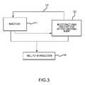
- FIG. 3depicts a process according to some embodiments of the present disclosure
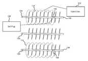
- FIG. 4is a side view of a horizontal drilling operation utilizing the diversion technique described herein where a gas (or foam) is introduced into the well;
- FIG. 5is a side view of the horizontal drilling operation utilizing the diversion technique described herein where a carrier liquid is introduced into the well;
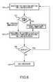
- FIG. 6is a flowchart illustrating the steps in utilizing the diversion technique described herein;
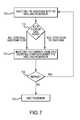
- FIG. 7is a flowchart illustrating another set of steps in utilizing the diversion technique described herein;
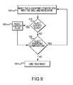
- FIG. 8is a flowchart illustrating yet another set of steps in utilizing the diversion technique described herein;
- FIG. 9is a flowchart illustrating another set of steps utilizing the diversion technique described herein.
- FIG. 10depicts a multi-well configuration according to an embodiment
- FIG. 11depicts a multi-well configuration according to an embodiment
- FIG. 12depicts a multi-well configuration according to an embodiment
- FIG. 13depicts a multi-well configuration according to an embodiment
- FIG. 14depicts a multi-well configuration according to an embodiment
- FIG. 15is a side view of a hydraulic fracturing operation showing high and low stress zones
- FIG. 16is a side view of a horizontal drilling operation utilizing the diversion technique described herein where a gas is introduced into the well;
- FIG. 17is a side view of the horizontal drilling operation utilizing the diversion technique described herein where a carrier liquid is introduced into the well;
- FIG. 18is a flowchart illustrating the steps in utilizing the diversion technique described herein;
- FIG. 19is a flowchart illustrating another set of steps in utilizing the diversion technique described herein.
- FIG. 20is a flowchart illustrating yet another set of steps in utilizing the diversion technique described herein.
- Hydraulic fracturinginvolves hydraulically fracturing the subterranean formation with a pressurized liquid or carrier, liquid, containing, water, proppant (e.g., sand or man-made alternative), and/or chemicals, that is injected into a wellbore.
- proppante.g., sand or man-made alternative
- the carrier liquidUpon pressurizing the wellbore with the carrier liquid, the formation fractures or cracks and the carrier fluid can leave behind proppant, which allows the hydrocarbons to flow more freely through the fractures and into the wellbore to be recovered.
- a downhole electric submersible pumpmay pump the hydrocarbons from the reservoir to overcome the hydrostatic head pressure of the hydrocarbons, or the hydrocarbons may flow freely up the wellbore without assistance.
- a pressurized liquid 102may cause multiple fractures 104 within the subterranean formation 106 .
- Fractures 104 formed by the pressurized liquid 102can be of varying sizes. Accordingly, larger fractures or pore volumes 108 may cause a lower stress zone 110 within the formation such that upon stimulation and re-stimulation of the well the carrier liquid 102 tends to concentrate in these lower stress zones 110 .
- These lower stress zones 110can be caused by hydrocarbon depletion, lower pore pressure, and/or higher permeability of the reservoir 106 .
- Permeability of the reservoircan, in part, depend on the extensiveness of fractures and/or pores, and the interconnectivity of the fractures and/or pores that create pathways for hydrocarbons to flow. As a result of the lower stress zones, the hydrocarbons are more likely to flow through these larger fractures or pore volumes 108 , and/or those with interconnectivity, until depletion.
- the fractures and/or pore volumes 104 of finer sizes 112 and/or those lacking interconnectivitytend to be concentrated in higher stress zones 114 such that the carrier liquid 102 is less likely to effectively hydraulically fracture those higher stress zones and thus influence the flow of hydrocarbons in these regions upon stimulation or re-stimulation.
- the pressure of the carrier liquid 102is generally evenly distributed along the wellbore in the treated area such that the carrier liquid I 02 remains concentrated in the lower stress zones 110 rather than the higher stress zones 114 .
- the higher stress zones 114in contrast to the lower stress zones 110 , can be caused by higher pore pressure, ineffective hydraulically fractured regions, lower permeability of the reservoir 106 , or generally less depleted portions of the reservoir 106 .
- the carrier liquid 102tends to not affect the higher stress zones 114 , which may contain hydrocarbons, unless additional systems and methods are employed.
- diverter systemsmay be used to divert the carrier liquid 102 from the lower stress zones 110 , which may be depleted from previous treatments, to the previously un-accessed, higher stress zones 114 . Diverting the carrier liquid 102 into these higher stress zones 114 may be difficult over large areas of the wellbore and reservoir for a number of reasons. In new wells, the difficulty may be due to differences in stresses from different lithologies or from different reservoir characteristics along the well. Differences in stress can be due to natural in-situ stress conditions or man-made activities such as well stimulation or depletion of fluids.
- the difficultymay be due to adequately blocking the fractures and/or pore volume 108 in the lower stress zones 110 such that the carrier liquid 102 pressurizes the fractures 112 of the higher stress zones 114 .
- Diverter systemsinclude the use of particulates (e.g., polymers) and chemical diverters within the carrier liquid 102 , among other methods, to block either the wellbore or the formation near the wellbore so that a portion of the carrier liquid 102 may be diverted to the fractures 112 in the higher stress zones 114 and also create new fractures in the higher stress zones.
- aspects of the presently disclosed technologyinvolve a diversion technique for use in vertical, deviated, or horizontal wells undergoing a stimulation process (e.g., initial stimulation or re-stimulation) to divert a carrier liquid from treating previously stimulated areas (i.e., lower stress zones of the formation) and to force the carrier liquid to treat previously unstimulated areas (i.e., higher stress zones of the formation).
- a stimulation processe.g., initial stimulation or re-stimulation
- the methods disclosedprovide cost-effective means for improving the well production.
- stimulation operationsare usually performed to enhance hydrocarbon (e.g. gas, oil, etc.) production into the wellbore and to enhance extraction of the hydrocarbons from the subterranean formation.
- liquid or solid formssuch as chemical solutions (e.g., a borate solution) or, particulates (e.g., polymers spheres), which can be costly and potentially ineffective in diverting fluid to the higher stress regions/zones of the reservoir.
- liquid- and solid-form diverterscan be problematic as they leave residue that can damage the subterranean formation and can lead to inhibited production from the well.
- the methods of the present disclosureare cost effective, operationally feasible based on current equipment available to the industry, and can enhance the rate of extraction of the hydrocarbons.
- the use of a gas as the diversion mediumallows for greater filling of the reservoir in lower stress zones such that a carrier liquid can be more efficiently diverted to the higher stress zones of the reservoir.
- the use of a gas as the diversion mediumalso has advantages in that no residue remains and the gas can be recovered during flowback. In certain instances, the gas may be recovered during flowback can be reused, recycled, or marketed.
- FIG. 1depicts a side view of a horizontal drilled well 100 treated according to a method of the prior art utilizing a fracturing liquid 102 to produce multiple fractures 104 within a subterranean formation 106 .
- the multiple fractures 104 produced by the pressurized liquid 102can vary in size.
- low stress zones 110contain larger fractures and/or pore volumes 108 than high stress zones 114 .
- re-stimulation or re-fracturing the fracturing liquid 102typically tends to concentrate in the larger fractures and/or larger pore volumes 108 of low stress zones 110 .
- These low stress zones 110tend to be zones of hydrocarbon depletion, lower pore pressure, higher permeability, or a combination thereof.
- Permeability of the reservoircan, in part, depend on the extensiveness and interconnectivity of the fractures and/or pores.
- hydrocarbon flowtypically depends on the extensiveness and/or interconnectivity of the fractures and/or pores that create pathways for the hydrocarbon.
- the hydrocarbonsare more likely to flow through these larger and/or more interconnected fractures and/or pore volumes 108 .
- the high stress zones 114tend to be zones having finer and/or less interconnected fractures and/or pore volumes 112 such that the fracturing liquid 102 is less likely to hydraulically fracture these high stress zones 114 . These finer and/or less interconnected fractures and/or pore volumes 112 can influence the flow of hydrocarbons in these regions upon stimulation or re-stimulation.
- the pressure of the fracturing liquid 102is generally distributed along the wellbore 118 in the treated area such that the pressurized fracturing liquid 102 can achieve the fracture gradient in the low stress zones 110 but not the high stress zones 114 .
- the high stress zones 114in contrast to the low stress zones 110 , can have one or more of higher pore pressure, ineffective hydraulically fractured regions, lower permeability, or generally less depleted portions of the subterranean formation 106 .
- the fracturing liquid 102is one or more of less likely to permeate these lower permeability and/or generally less depleted portions of the subterranean formation 106 and less likely to achieve the fracture gradient threshold in these higher pore pressure, high stress zones 114 . Accordingly, unless additional systems and methods are employed the hydrocarbons in these high stress zones 114 are difficult to produce due to high pore pressures and/or low permeability of these zones.
- diverter systemscan be used to divert the fracturing liquid 102 from the low stress zones 110 , which can be depleted from previous treatments, to the previously un-accessed, high stress zones 114 . Diverting the fracturing liquid 102 into these high stress zones 114 can be difficult over large areas of the wellbore 118 and reservoir for a number of reasons. In new wells, the difficulty can be due to differences in stresses from different lithologies or from different reservoir characteristics along the wellbore 118 . Differences in stress can be due to natural in-situ stress conditions or man-made activities such as well stimulation or depletion of fluids, such as hydrocarbons.
- the difficultycan be due to adequately blocking the fractures and/or pore volume 108 in the low stress zones 110 such that the fracturing liquid 102 pressurizes the high stress zones 114 .
- Diverter systemscan include the use of particulates (e.g., inorganic and/or organic polymeric particulates) and chemical diverters within the fracturing liquid 102 , among other methods, to block either the wellbore 118 or the subterranean formation 106 near the wellbore 118 so that a portion of the fracturing liquid 102 can be diverted to the high stress zones 114 and create new fractures 112 in the high stress zones 114 .
- particulatese.g., inorganic and/or organic polymeric particulates
- chemical diverterswithin the fracturing liquid 102
- aspects of the presently disclosed technologyinvolve a diversion technique for use in vertical, deviated, or horizontal wells undergoing a stimulation process (e.g., initial stimulation or re-stimulation).
- the presently disclosed technologycan divert a fracturing liquid from treating one or more previously stimulated areas (i.e., low stress zones of the formation) to one or more previously unstimulated zones (i.e., high stress zones of the formation).
- a previously unstimulated areacan refer to one or more of a previously unstimulated high stress zone, a previously unstimulated low stress zone, a previously partially stimulated high stress zone, a previously partially stimulate low stress zone, or a combination thereof.
- the methods disclosed hereincan provide cost-effective means for improving hydrocarbon production from a well.
- stimulation operationsare usually performed to enhance hydrocarbon (e.g. gas, oil, etc.) production into the wellbore and to enhance extraction of hydrocarbons from the subterranean formation 206 .
- hydrocarbone.g. gas, oil, etc.
- the above-described initial well treatments and/or subsequent well treatmentscan direct a fracturing liquid 202 to one or more previously unstimulated zones.
- the previously unstimulated zonescan be high stress zones 214 .
- aspects of the present disclosurecan involve a technique for use in vertical, deviated, or horizontal wells undergoing a stimulation process (e.g., initial stimulation or re-stimulation) to direct a fracturing liquid 202 to treat a previously unstimulated zone.
- a stimulation processe.g., initial stimulation or re-stimulation
- liquid or solid formssuch as chemical solutions (e.g., a borate solution) or, particulates (e.g., polymers spheres).
- the methods of the present disclosureare cost effective, operationally feasible based on current equipment available to the industry, and can enhance the rate of extraction of the hydrocarbons.
- a gas (or foam)as the diversion medium allows for greater filling of the reservoir in low stress zones such that a fracturing liquid can be more efficiently diverted to the higher stress zones of the reservoir.
- the use of a gas (or foam) as the diversion mediumalso has advantages in that the gas (or gas component of the foam) can be recovered during flowback. In certain instances, the gas (or gas component of the foam) can be recovered during flowback can be reused, recycled, or marketed.
- the methods of the present disclosurecan use one of a gas as the medium for treating the previously unstimulated zones.
- the gascan generally refer to any chemical composition in the gaseous phase including but not limited to a single phase gaseous system, a foam (that is, a gas entrapped within a liquid), and a combination thereof (that is, a system having some gas entrapped within a liquid and some gas not entrapped within a liquid). It is believed that the gas can more effectively penetrate one or both of the fractures and pore volumes of the previously unstimulated zones than the fracturing liquid 202 .
- the gascan more easily fill and pressurize the one or both of the factures and pore volumes of the previously unstimulated zones more easily than the fracturing liquid 202 . Furthermore, it is believed that one or both of the factures and pore volumes of the previously unstimulated zones filled and/or pressurized with a gas can be efficiently stressed and fractured.
- the methodcan include stimulating a well and reservoir by alternating or simultaneously introducing a gas diverter and a conventional diverter (e.g., chemical, biological, or mechanical diverter systems known and unknown).
- a gas diverter and a conventional divertere.g., chemical, biological, or mechanical diverter systems known and unknown.
- the methodincludes introducing a gas and a conventional diverter system into a reservoir.
- the gas and conventional diverter systemcan be introduced simultaneously or one after the other in any order and/or combination.
- the gascan be introduced prior to the conventional diverter system; or a first portion of the gas can be introduced prior to the conventional diverter system and a second portion of gas can be introduce after the conventional diverter system; or the convention diverter system can be introduced prior to gas being introduced.
- FIGS. 2A and 2Bdepict a side view of a well configuration 200 in accordance some embodiments of the present disclosure treated according to process 300 depicted in FIG. 3 .
- a gas (in any of the forms as described herein) 216is introduced and/or injected into a well and reservoir 220 comprising subterranean formation 206 .
- the subterranean formation 206may include any type of rock and/or mineral or combination and/or mixture of any known rocks and minerals.
- the subterranean formation 206can comprise one or more of sedimentary rocks, igneous rocks, and metamorphic rocks.
- Non-limiting examples of sedimentary rockscan include sandstone, limestone, and shale.
- Igneous rockscan include without limitation granite and andesite.
- Metamorphic rockscan include without limitation gneiss, slate, marble, schist, and quartzite.
- the subterranean formation 206can comprise a shale formation, a clay formation, a sandstone formation, a limestone formation, a carbonate formation, a granite formation, a marble formation, a coal bed, or a combination thereof.
- the gas 216is introduced and/or injected into the subterranean formation 206 at sufficient pressure to pressurize first portion fractures and pore volumes 208 .
- the gas 216can also infiltrate second portion fractures and pore volumes 212 .
- the first portion fractures and pore volumes 208are contained in first stress zone 210 and the second portion fractures and pore volumes 212 are contained in second stress zone.
- the first stress zone 210is typically of lower stress than the second stress zone 214 .
- the second stress zone 214is usually of higher stress than the first stress zone 210 .
- the injection pressure of the gas 216depends on the fracture gradient of the low stress zone 210 .
- the fracture gradientis the pressure required to induce a facture in the rock, such as the subterranean formation 206 , at a given depth, as such the fracture gradient units are typically expressed in psi/ft or kPa/m.
- the fracture gradientcan be a function of many factors including but not limited to overburden stress, Poisson's ratio of the formation (rock), pore pressure gradient, formation (rock) matrix stress coefficient, and matrix stress.
- the gas 216is injected into the wellbore 218 at a pressure that is less than the fracture gradient(s) of the first 210 and/or second 214 stress zones (and/or other subsurface formations along the wellbore 218 ) to inhibit (further) fracturing of one or more of these zones.
- the injection pressure of the gas 216is generally maintained below the fracture gradient the subterranean formation 206 .
- the injection pressure of the gas 216is maintained below the fraction gradient of one or more the first 210 and second 214 stress zones. Even more generally the injection pressure of the gas 216 is maintained below the fracture gradient of subterranean formation 206 including the first 210 and second 214 stress zones during substantially the entire duration of injecting the gas 216 . Typically, the injection pressure of the gas 216 is maintained below the fracture gradient of subterranean formation 206 including the first 210 and second 214 stress zones during substantially at least about 50% of the entire duration of injecting the gas 216 . More typically, at least about 75%, even more typically at least about 90%, and yet even more typically at least about 95% of the entire duration of the injecting the gas 216 .
- the injecting of gas 216is continued until a desired pressure is reached within the well and/or reservoir 220 .
- the injecting of the gas 216is continued to a pressure of no more than the fracture gradient. More typically, the gas 216 is continued to a pressure of one of no more than about 99% of the fracture gradient, even more typically to a pressure of no more than about 98% of the fracture gradient, yet even more typically to a pressure of no more than about 97% of the fracture gradient, still yet even more typically to a pressure of no more than about 96% of the fracture gradient, still yet even more typically to a pressure of no more than about 95% of the fracture gradient, still yet even more typically to a pressure of no more than about 90% of the fracture gradient, still yet even more typically to a pressure of no more than about 85% of the fracture gradient, still yet even more typically to a pressure of no more than about 80% of the fracture gradient, still yet even more typically to a pressure of no more than about 75% of the fracture gradient, still yet
- Factors that can affect the volume of gas 216 to be introduced in the wellbore 218include the size (that is volume) of the subterranean formation 206 in fluid communication with wellbore 218 , the size (volume) of the depleted regions of the subterranean formation 206 , the size (volume) the pore volumes and fractures, leak off rate of the gas 216 , and the reservoir pressure of the subterranean formation 206 prior to the injection of gas 216 .
- the volume of the gas 216 injected into the subterranean formation 206can range from about 1,000 standard cubic feet (scf) to about 100,000,000 scf. In some embodiments, the volume of gas 216 injected into the subterranean formation 206 can be greater than about 1 ⁇ 109 scf.
- the volume of gas injected into the subterranean formation 206is typically at least about 50,000 scf, more typically at least about 100,000 scf, even more typically at least about 150,000 scf, yet even more typically at least about 200,000 scf, still yet even more typically at least about 250,000 scf, still yet even more typically at least about 300,000 scf, still yet even more typically at least about 350,000 scf, still yet even more typically at least about 400,000 scf, still yet even more typically at least about 450,000 scf, still yet even more typically at least about 550,000 scf, still yet even more typically at least about 600,000 scf, still yet even more typically at least about 650,000 scf, still yet even more typically at least about 700,000 scf, still yet even more typically at least about 750,000 scf, still yet even more typically at least about 800,000 scf, still yet even more typically at least about 850,000 scf, still yet
- the volume of gas 216is no more than about 200,000,000 scf, more commonly no more than about 300,000,000 scf, even more commonly no more than about 400,000,000 scf, yet even more commonly no more than about 500,000,000 scf, and still yet it is within the scope of some embodiments of this invention to inject up to about 1,000,000,000 scf.
- volume of gas 216 injected into the subterranean formation 206can be expressed in terms of standard cubic feet of gas (scf) per net linear feet of the wellbore 218 in contact with and in fluid communication with the subterranean formation 206 (lf CA ).
- the volume of gas 216 injected into the subterranean formation 206is at least about 500 scf/lf CA , more typically at least about 525 scf/lf CA , even more typically at least about 550 scf/lf CA , yet even more typically at least about 575 scf/lf CA , still yet even more typically at least about 600 scf/lf CA , still yet even more typically at least about 625 scf/lf CA , still yet even more typically at least about 650 scf/lf CA , still yet even more typically at least about 675 scf/lf CA , still yet even more typically at least about 700 scf/lf CA , still yet even more typically at least about 725 scf/lf CA , and yet still even more typically at least about 750 scf/lf CA .
- the volume of gas 216 injected into the subterranean formation 206is no more than about 5,000 scf/lf CA , even more commonly no more than about 4,750 scf/lf CA , yet even more commonly no more than about 4,500 scf/lf CA , still yet even more commonly no more than about 4,250 scf/lf CA , still yet even more commonly no more than about 4,000 scf/lf CA , still yet even more commonly no more than about 3,750 scf/lf CA , still yet even more commonly no more than about 3,500 scf/lf CA , still yet even more commonly no more than about 3,250 scf/lf CA , still yet even more commonly no more than about 3,000 scf/lf CA , still yet even more commonly no more than about 2,900 scf/lf CA , still yet even more commonly no more than about 2,800 scf/lf CA , still yet even more commonly
- the gas 216can be injected at a rate of about 30 to about 500,000 scf/min. Generally, the gas 216 can be injected at a rate of about 10,000 to about 20,000 scf/min. Typically, the injection rate of the gas 216 is about 30 scf/min or more, more typically about 50 scf/min or more, even more typically about 100 scf/min or more, yet even more typically about 200 scf/min or more, still yet even more typically about 300 scf/min or more, still yet even more typically about 400 scf/min or greater, still yet even more typically about 500 scf/min or more, still yet even more typically about 600 scf/min or more, still yet even more typically about 700 scf/min or more, still yet even more typically about 800 scf/min or more, still yet even more typically about 900 scf/min or more, and yet still even more typically about 1,000 scf/min
- the gas 216can be injected at a rate of no more than about 500,000 scf/min, more commonly at rate of no more than about 450,000 scf/min, even more commonly at rate of no more than about 400,000 scf/min, yet even more commonly at rate of no more than about 350,000 scf/min, still yet even more commonly at rate of no more than about 300,000 scf/min, still yet even more commonly at rate of no more than about 250,000 scf/min, still yet even more commonly at rate of no more than about 200,000 scf/min, still yet even more commonly at rate of no more than about 150,000 scf/min, and yet still even more commonly at rate of no more than about 100,000 scf/min.
- the gas 216can include any number of gasses.
- the gas 216can comprise nitrogen, hydrogen, methane, ethane, propane, butane, carbon dioxide, any inert gas, or any combination thereof.
- the gas 216can be injected into the well and reservoir 220 in a number of ways.
- the gas 216can be delivered to wellhead 226 by one or more of a storage truck, a pipeline, a storage tank, a gas producing well, or other suitable gas supply sources.
- the one or more of the storage truck, pipeline, storage tank, gas producing well, or other suitable gas supply sourceare interconnect to and in fluid communication with the wellhead 226 and the wellbore 218 .
- the wellbore 218is in fluid communication with subterranean formation 206 .
- the gas 216can be a gas in the gas phase, a gas in the liquid phase, or a combination thereof. In some embodiments, the gas 216 can be in the gas phase. In such embodiments, the gas 216 can be pumped directly into the wellbore 218 from wellhead 226 . In some embodiments, the gas 216 can be in the liquid phase when introduced at the wellhead 226 . In such embodiments, the liquid phase gas 216 can be directly injected into the wellbore 218 or it can be heated one or more during or after being injected into the wellbore 218 .
- the liquid phase gas 216is generally sufficiently heated during or after being injected into the wellbore 218 that it is substantially in gas phase when it infiltrates the pore volumes and/or fractures of subterranean formation 206 .
- the gas 216when the gas 216 is in a liquid phase when introduced to the well and reservoir 220 , the gas 216 can be allowed to remain in the well and reservoir 220 for a sufficient amount of time such that the reservoir temperature causes the liquid phase gas 216 to undergo a phase change from a liquid phase to a gas phase before and/or substantially simultaneously with infiltration of the fractures and pore volumes of the subterranean formation 206 .
- the well and reservoir 220can have a reservoir temperature from about 120 degrees Fahrenheit to about 600 degrees Fahrenheit, or even greater than about 600 degrees Fahrenheit.
- a gas 216 in a liquid phasecan have a temperature less than the reservoir temperature.
- a gas 216 in the liquid phasecan have a temperature from about ⁇ 69 degrees Fahrenheit to about 80 degrees Fahrenheit. It can be appreciated that the higher reservoir temperature of the well and reservoir 220 can provide sufficient heat to the liquid phase gas 216 to induce a phase transition from the liquid phase to the gas phase.
- the gas 216can infiltrate the subterranean formation 206 from about 1 to about 7,000 feet from one or more of the wellbore 218 or perforation tunnel. More typically, the gas 216 can infiltrate the subterranean formation 206 from about 10 to about 5,000 feet from one or more of the wellbore 218 or perforation tunnel. More typically, the gas 216 can infiltrate the subterranean formation 206 from about 100 to about 3,000 feet from one or more of the wellbore 218 or perforation tunnel.
- the gas 216can infiltrate the subterranean formation 206 no more than about 7,000 feet, more commonly no more than about 5,000 feet, or even more commonly no more than about 3,000 feet from one or more of the wellbore 218 or perforation tunnel.
- the gas 216can infiltrate the subterranean formation 206 more than about 1 foot, more usually more than about 10 feet, or even more usually more than about 100 feet from one or more of the wellbore 218 or perforation tunnel.
- the gas 216is generally introduced into the well and/or reservoir 220 through wellhead 226 .
- the flow of the gas 216can be one or more of monitored and controlled by a control system.
- the control systemcan include one or more of (a) pressure sensor(s), gauge(s) and switch(es) arrangement any manner or combination thereof.
- the injecting of the gas 216can be in a substantially uninterrupted continuous flow until the desired volume of the gas 216 has been injected.
- the injecting the gas 216can intermittently, where the flow of the gas 216 can be started and stopped in succession any number of times until the desired volume of gas 216 has been injected.
- the gas 216can be maintained in the well and/or reservoir 220 for a dwell period of time.
- the dwell period of timecan comprise little, if any, time. However, in some embodiments, a dwell period of time exists between the halting and the starting of the injection of gas 216 .
- the dwell period of timecan be long (such as hours or days) or short (such as minutes or hours).
- the gas 216can be injected in the liquid phase where a dwell period of time can be needed for the liquid phase to undergo a phase transition to the gas phase.
- the dwell period of timecan be as short as about 5 minutes or as long as about 24 hours.
- the dwell timecan be less than one hour. In some embodiments, the dwell time can be less than thirty minutes. In other embodiments, the dwell time can be no more than twenty four hours. In other embodiments, the dwell time can be more than twenty four hours.
- the gas 216can be in the form of a foam.
- the foamcan be injected into the well and reservoir 220 .
- Foam qualityis conventionally defined as the volume percent gas within the foam at a specified pressure and temperature.
- the volume % valuegenerally refers to the volume % of gas in the foam.
- the balance of the volume % of the foamis usually liquid.
- the quality of the foam injected into the well and reservoir 220is about 30 volume/0 or more.
- the quality of foamis about 40 volume % or more, even more typically 50 volume % or more, yet even more typically about 60 volume/0 or more, still yet even more typically about 70 volume % or more, still yet even more typically about 80 volume % or more, or yet still even more typically about 90 volume % or more. That is, in some embodiments, the quality of the foam can be greater than about 30 volume % gas in the foam with the balance being liquid. That is, in some embodiments, the quality of the foam can be greater than about 40 volume % gas in the foam with the balance being liquid. That is, in some embodiments, the quality of the foam can be greater than about 50 volume % gas with the balance being liquid.
- the quality of the foamcan be greater than about 60 volume % gas in the foam with the balance being liquid. That is, in some embodiments, the quality of the foam can be greater than about 70 volume % gas in the foam with the balance being liquid. That is, in some embodiments, the quality of the foam can be greater than about 80 volume % gas in the foam with the balance being liquid. That is, in some embodiments, the quality of the foam can be greater than about 80 volume % gas in the foam with the balance being liquid. That is, in some embodiments, the quality of the foam can be greater than about 90 volume % gas in the foam with the balance being liquid.
- the gascan be in the form of a foam.
- the foamcan contain more gas by volume than liquid by volume. It can be appreciated that in some embodiments the foam can contain less gas by volume than liquid by volume.
- the foamcan have no more than about 50 volume % liquid, no more than about 45 volume % liquid, no more than about 40 volume % liquid, no more than about 35 volume % liquid, no more than about 30 volume % liquid, no more than about 25 volume % liquid, no more than about 20 volume % liquid, no more than about 15 volume % liquid, no more than about 10 volume % liquid, no more than about 5 volume % liquid, no more than about 2 volume % liquid, no more than 1 volume % liquid, or no more than about 0.1 volume %) liquid.
- the foamcan have at least about 1 volume % liquid, at least about 5 volume % liquid, more typically at least about 10 volume % liquid, or at least about 15 volume % liquid.
- the percent by volume of the liquid and/or gasis typically measured at the wellhead 226 prior to the injection of the foam into the wellbore 218 .
- volume % of liquid in foamcan vary according to temperature and pressure.
- the volume % of liquid in the foamgenerally correspond without limitation to those measured at the temperature and pressure of the foam immediately prior to the injection of the foam at the wellhead 226 .
- the gas 216may or may not be substantially free of particulates.
- the particlescan comprise, a solid, semi-solid, a liquid diverting agent, or any combination thereof.
- the gas(as measured at the surface) has no more than about 5 volume % particulates, more typically no more than about 2.5 volume % particulates, more typically no more than about 1 volume % particulates, more typically no more than about 0.75 volume % particulates, more typically no more than about 0.5 volume %) particulates, more typically no more than about 0.25 volume % particulates, and even more typically no more than about 0.1 volume % particulates.
- particulatesare beneficial in some applications, particulate diverting agents, in particular, can cause production problems downhole.
- the gas 216is generally substantially free of particles.
- the gas 216can be substantially compressible. Typically, the gas 216 is compressed within the wellbore 218 and the reservoir. It can be further appreciated that a fracturing liquid 202 , which is injected in step 320 following the injection of the gas 216 in step 310 . It can be appreciated that the fracturing liquid 202 is generally substantially incompressible. Compared with the fracturing liquid 202 , the gas 216 more easily fills the fractures and/or pore volumes of the subterranean formation 206 .
- Ability of the gas 216 to more easily fill the fractures and/or pore volumes of subterranean formation 206 than the fracturing liquid 202can be due one or more of the following: (a) the higher surface tension of the fracturing liquid 202 , compared to the gas 216 ; (b) the lower density of the gas 216 compared to the fracturing liquid 202 ; (c) the inability of the fracturing liquid 202 to wet the subterranean formation 206 ; and (d) the ability of the gas 216 to diffuse into the subterranean formation 206 compared to the impermeability of fracturing liquid 202 to subterranean formation 206 .
- the gas 216in any of the forms as described herein will fill or occupy fractures in the formations along the wellbore 218 (e.g., the first portion fractures and pore volumes 208 which is often already fractured and/or has a low pore pressure) and, when contacted with the fracturing liquid 202 , will compress until a fracture gradient is reached, thereby causing fracture initiation and propagation in a previously unstimulated zone.
- the one or more of fractures and pore volumes 208are in first stress zone 210 of subterranean formation 206 .
- the injected gascan infiltrate and pressurize the subterranean formation 206 and the reservoir holding the hydrocarbons.
- the gascan travel through a network of the first portion fractures and pore volumes 208 .
- the first portion factures and pore volumes 208can be man-made, naturally occurring or a combination of naturally occurring and man-made. That is, the first portion factures and/or pore volumes 208 can be preexisting within the natural formation and/or regions of hydrocarbon depletion.
- the gas 216Upon infiltration, the gas 216 will occupy the first portion fractures and pore volumes 208 in the subterranean formation 206 .
- This gas infiltration into the first portion factures and pore volumes 208can create a sufficient pressure in the first stress zone 210 and the first factures and pore volumes 208 to allow a fracturing liquid 202 to fracture previously unstimulated zones.
- These previously unstimulated zones fractured by the fracturing liquid 202can be portions of the subterranean formation 206 that are a significant distance from wellbore 218 (i.e., far-field) compared any previous stimulated areas.
- these previously unstimulated areas fractured by the fracturing liquid 202can be portions of the subterranean formation 206 previously having little, if any, of one or both hydrocarbon permeability and production prior to being fractured by the fracturing liquid 202 .
- the infiltration of the gas 216 into the first portion factures and pore volumes 208can create a barrier for the fracturing liquid 202 that is subsequently delivered into the wellbore 218 and diverted to the second stress zone 214 .
- the gas 216 in the stimulation networkcan build a sufficient pressure in the network allowing subsequently delivered fracturing liquid 202 to be diverted into previously untreated areas of the subterranean formation 206 .
- this methodwill allow for the diversion of the fracturing liquid 202 to a portion of the subterranean formation 206 that is a significant distance from the wellbore 218 (i.e. far-field).
- the fractures generated in the previously unstimulated zonescan be in some embodiments the second portion fractures and pore volumes 212 . It is also believed that that the fractures generated in the previously unstimulated zones can be in some embodiments new fractures and pore volumes in the first stress zone 210 that are not part of the first portion fractures and pore volumes 208 . Moreover, it is believed that in some embodiments the fractures generated in the previously unstimulated zones can be a combination of the second portion fractures and pore volumes 212 and the new fractures and pore volumes in the first stress zone 210 that are not part of the first portion fractures and pore volumes 208 .
- the fracturing liquid 202can be without limitation one or more of slick-water, a gel, and a fracturing foam.
- the slick watercomprises a low viscosity water-based fluid. More commonly, the slick water comprises a low viscosity water-based fluid with a proppant.
- the gelcan comprise one or more of a borate, hydroxypropyl guar (HPG), carboxymethyl hydroxypropyl guar (CMHPG), and carboxymethyl cellulose (CMC).
- the fracturing foamcan comprise one or more of nitrogen and water with gel, carbon dioxide, propane, and combinations thereof.
- the fracturing liquid 202 or an amount of water used in the fracturing liquid 202can be supplied by storage tanks, naturally formed features (e.g., spring), a pipeline, etc.
- the fracturing liquid 202can be continuously injected or it can be intermittently injected into the wellbore 218 and reservoir. In the case of intermittent injection, the injecting of the fracturing liquid 202 can be halted for a period of time before continuing with injecting process.
- the period of time between injectionscan be a period of minutes, hours, or days.
- the period of time between injectionscan be at least about 1 minute, at least about 5 minutes, at least about 10 minutes, at least about 20 minutes, at least about 30 minutes, at least about 45 minutes, at least about 1 hour, at least about 2 hours, or at least about 3 hours, among other time periods.
- the initial gas 216 injectiontypically goes into the low stressed pore areas and increases the stress of the pore areas. It is believed that the leak-off rate of the injected fracturing liquid 202 into the pores is slowed by the gas 216 . Fractures are generally larger than pores. With respect to fractures, the fracturing liquid 202 is not believed to force the gas 216 out of the fractures in the low stress zones due to the effects of frictional resistance to multi-phase flow (including both liquid and gas). When the injection pressure is more than the frictional resistance, the fracturing liquid 202 is believed to displace the gas 216 from the fractures.
- the resistance to flowwill increase above the injection pressure, thereby preventing the fracturing liquid 202 from displacing the gas 216 from the fracture.
- fracture initiation and propagationcommence, such as in the high stress zones.
- the gas 216is thus believed to block the fracturing liquid 202 from propagating the fracture in the low stress zone.
- injections of gas 216 and fracturing liquid 202are alternated, it is believed that the gas 216 will enter the subterranean formation 206 having the next lowest fracture gradient.
- the gas 216(in any of the forms as described herein) can fill and/or occupy the fractures and pore volumes in the subterranean formation 206 along the wellbore 218 .
- the gas 216can fill and/or occupy the factures and pore volumes in one or more of the first 210 and second 214 stress zones.
- the gas 216 in the one or more of the first 210 and second 214 stress zonesis contacted with the pressurized fracturing liquid 202 , the gas 216 can be compressed. That is, the gas 216 can be pressurized within the one or more of the first 210 and second 214 stress zones.
- the gas 216 compressed in the one or more of the first stress zones 210 and second stress zones 214can be pressurized until the fracture gradient of one or both of first 210 and second 214 stress zones is reached, thereby causing one or more fractures to initiate and propagation within the one or both of the first 210 and second 214 stress zones. It is further believed that at least some, if not most, of the one or more fractures initiated and propagated by the compressed gas can be in previously unstimulated zones.
- the compressed gas 216can fill, occupy and pressurize the portions off the first 210 and/or second 214 stress zones that the previous pressurized fracturing fluid could not and thereby fracture the previously unstimulated portions of the first 210 and/or second 214 stress zones.
- the fracturing liquid 202can or cannot include a diverting agent.
- the diverting agentcan be a chemical, a mechanical device, or a biological material.
- the diverting agentcan be a particulate material.
- the diverting agentcan be any diverting agent commonly used in diverting systems and any of the others not commonly used.
- the particulate materialscan be blended with the fracturing liquid 202 to form the diverting composition and then injected into the wellbore 218 .
- Examples of diverting agents that can be mixed with the fracturing liquid 202include, but are not limited to, sand, ceramic proppant, resin coated proppant (ceramic, sand or other), salts, water soluble balls of polyesters/polylactide copolymer compounded with plasticizers, degradable fibers, starches (e.g., corn starch), gels, guar, ceramic beads, bauxite, glass microspheres, synthetic organic beads, sintered materials and combinations thereof, polymer materials, fluoro-polymer particulates (such as, but not limited to TEFLONTM fluoro-polymer particulates), nut shell pieces, seed shell pieces, cured resinous particulates comprising nut shell pieces, cured resinous particulates including seed shell pieces, fruit pit pieces, cured resinous particulates including fruit pit pieces, wood, composite particulates and any combinations thereof.
- sandceramic proppant
- resin coated proppantceramic, sand or other
- the diverting agentcan be degradable and can include but not be limited to degradable polymers, dehydrated compounds, and mixtures thereof.
- degradable polymersthat can be used as a diverting agent can include, but not be limited to homopolymers, and random, block, graft, and star- or hyper-branched polymers.
- suitable polymersinclude polysaccharides such as dextran or cellulose, chitin, chitosan, proteins, aliphatic polyesters, poly(lactide), poly(glycolide), poly( ⁇ -caprolactone), poly(hydroxybutyrate), poly(anhydrides), aliphatic polycarbonates, poly(ortho esters), poly(amino acids), poly(ethylene oxide), and polyphosphazenes.
- Polyanhydridesare another type of suitable degradable polymer. Examples of suitable polyanhydrides include poly(adipic anhydride), poly(suberic anhydride), poly(sebacic anhydride), and poly(dodecanedioic anhydride). Other suitable examples include, but are not limited to, poly(maleic anhydride) and poly(benzoic anhydride). These and other diverting agents can be used in the embodiments described herein.
- the fracturing liquid 202can contain a diverting agent.
- a diverting agentthat is, a composition containing fracturing liquid and a diverting agent
- step 320can include injecting the fracturing liquid 202 with or without a diverting agent mixed with the fracturing liquid 202 into the wellbore 218 such that the fracturing liquid 202 , with or without the diverting agent, pressurizes the subterranean formation 206 and initiates and propagates one or more fractures in previously unstimulated zones of the subterranean formation 206 .
- the fracturing liquid 202Without injecting the gas 216 into the wellbore 218 , the fracturing liquid 202 , with or with the diverting agent, would not be diverted to the previously unstimulated zones and would otherwise infiltrate the previously stimulated fractures. In other words, sufficiently pressurizing the previously stimulated fractures can cause the subsequently injected fracturing liquid 202 , with or without diverting agent, to bypass the pressurized, gas-filled previously stimulated fractures and infiltrate the previously unstimulated zones of the subterranean formation 206 . It can be appreciated that the infiltration of the previously unstimulated zones by the fracturing liquid 202 can fracture at least some of the previously unstimulated zones of the subterranean formation 206 .
- the fracturing liquid 202without the injection of the gas 216 into the wellbore 218 , the fracturing liquid 202 , with or with the diverting agent, would not be diverted to the second portion of the subterranean formation 206 and would otherwise infiltrate the first portion of the subterranean formation 206 .
- sufficiently pressurizing the first portion of the subterraneancan cause the subsequently injected fracturing liquid 202 , with or without diverting agent, to bypass the pressurized, gas-filled first portion of the subterranean formation 206 and infiltrate the second portion of the subterranean formation 206 .
- the infiltration of the second portion of the subterranean formation 206 by the fracturing liquid 202can fracture at least some of the second portion of the subterranean formation 206 .
- the first stress zone 210has a lower stress than the second stress zone 214 . Even more generally, the first stress zone 210 contains previously stimulated, first portion fractures and pores volumes 208 .
- the fracturing liquid 202without the injection of the gas 216 into the wellbore 218 , the fracturing liquid 202 , with or with the diverting agent, would not be diverted to the second stress zone 214 of the subterranean formation 206 and would otherwise infiltrate the first portion fractures and pore volumes 208 .
- sufficiently pressurizing the first portion fractures and pore volumes 208can cause the subsequently injected fracturing liquid 202 , with or without diverting agent, to bypass the pressurized, gas-filled first portion of the fractures and pore volumes 208 and infiltrate the second stress zone of the subterranean formation 206 .
- the infiltration of the second stress zone of the subterranean formation 206 by the fracturing liquid 202can fracture at least some of the second stress zone of the subterranean formation 206 .
- the gas 216can infiltrate and pressurize the fractures and/or pore volumes in one or both of the first and second portions of the subterranean formation 206 prior to the introduction of the fracturing liquid 202 to one or both of the first and second portions of the subterranean formation 206 . Furthermore, it is believed that the gas 216 can infiltrate and pressure fractures and/or pore volumes that the fracturing liquid 202 is substantially unable to infiltrate and pressurize.
- the gas 216can infiltrate and pressure fractures and/or pore volumes that the fracturing liquid 202 is substantially unable to infiltrate and pressurize under the pressure that the fracturing liquid 202 is introduced into the subterranean formation 206 .
- the gas 216 within the fractures and/or pore volumes of subterranean formation 206is further pressurized by the fracturing liquid 202 .
- This further pressurization of the gas 216 within the fractures and/or pore volumesone or both of: (a) forms barrier between fracturing liquid 202 and the gas filled factures and pore volumes and (b) achieves a sufficient pressure within the gas filled fractures and pore volumes to fracture one or more of the gas filled fractures and/or pore volumes.
- the fractures that develop in the one or more of the gas filled fractures and/or pore volumescan be in one or more of the first 210 and second 214 stress zones are new fractures and were not previous manmade and/or naturally occurring fractures.
- the second stress zone 214has a greater stress than the first stress zone 210 .
- the first stress zone 210has a greater stress than the second stress zone 214 .
- the injecting of the gas 216is maintained for a period of time. It can be appreciated that period of injecting the gas 216 generally refers to the period starting with the injection of the gas 216 and ending with the starting of the injecting of the fracturing liquid 202 . Typically, the period of injecting the gas 216 is about 0.1 hours or more.
- the period of injecting the gasis about 0.2 hours or more, even more typically about 0.3 hours or more, yet even more typically about 0.4 hours or more, still yet even more typically about 0.5 hours or more, still yet even more typically about 0.6 hours or more, still yet even more typically about 0.7 hours or more, still yet even more typically about 0.8 hours or more, still yet even more typically about 0.9 hours or more, still yet even more typically about 1.0 hour or more, still yet even more typically about 1.5 hours or more, and yet still even more typically at least about 2.0 hours or more.
- the period of injecting the gas 216can commonly be no more than about 30 days, even more commonly no more than about 25 days, even more commonly no more than about 20 days, yet even more commonly no more than about 19 days, still yet even more commonly no more than about 18 days, still yet even more commonly no more than about 17 days, still yet even more commonly no more than about 16 days, still yet even more commonly no more than about 15 days, still yet even more commonly no more than about 14 days, still yet even more commonly no more than about 13 days, still yet even more commonly no more than about 12 days, still yet even more commonly no more than about 11 days, and yet sill even more commonly no more than about 10 days.
- the gas 216can be injected into the wellbore 218 over an extended period of time.
- the gas 216can be injected over a period of time that can be minutes, hours, days, or months, depending on a number of factors.
- the gas 216can be injected over a period of time of more than about 2 hrs.
- the gas 216can be injected over a period of time of more than a day.
- the gas 216can be injected into the wellbore 218 from a neighboring natural gas well.
- the pressure at wellbore 218can be checked during and/or any time period after the injection of the gas 216 to determine if the pressure is sufficient for the introduction of the fracturing liquid 202 . If the pressure is not sufficient, additional gas 216 needs to be injected into the wellbore 218 directly or through the neighboring natural gas well. It can be appreciated that it is possible for weeks to go by with intermittent addition of gas 216 into the wellbore 218 before a sufficient pressure is reached to begin introduction of the fracturing liquid 202 .
- sufficiently pressurizing the first 210 and second 214 portions of the subterranean formation 206 with gas 216 prior to the injecting and the fracturing liquid 202 , with or without a diverting agent,causes the injected fracturing liquid 202 to one or more of permeate, fill, occupy, and pressurize one or more of the fractures and pore volumes of previously unstimulated and/or under stimulated zones of one or more of the first 210 and second 214 portions of the subterranean formation 206 .
- step 320can include introducing the fracturing liquid 202 , with or without a diverting agent, into the wellbore 218 and reservoir 220 after step 310 to pressurize the subterranean formation 206 .
- the pressurization of the subterranean formation 206 by the fracturing liquid 202is sufficient to fracture a portion of the subterranean formation 206 .
- the introduction of the fracturing liquid 202 into the subterranean formation 206can pressurize one or more of the first and second portions of the subterranean formation 206 .
- introduction of the fracturing liquid 202 into the subterranean formationcan pressurize one or both of the first stress zone 210 and the second stress zone 214 .
- the second stress zone 214has a higher stress than the first stress zone 210 .
- one of first 210 and second 214 stressis pressurized more than the other.
- the first stress zone 210is pressurized more than the second stress zone 214 .
- the second stress zone 214is pressurized more than the first stress zone 210 .
- the fracturing liquid 202pressurizes the second stress zone 214 more than the first stress zones 210 , thereby fracturing the second stress zone 214 to a greater extent than the first stress zone 210 .
- the gas 216 and diverting agentwhen the fracturing liquid 202 contains a diverting agent substantially impedes and/or diverts pressurization of the first stress zone 210 by the fracturing liquid 202 to substantially fracture first stress zones 210 .
- the fracturing liquid 202can typically sufficiently pressurize the second stress zone 214 to substantially fracture the second stress zone 214 .
- the second fractures and pore volumes 212are usually formed in the second stress zone 214 by the pressurized fracturing liquid 202 .
- the fracturing liquid 202can be injected into the well and/or reservoir 220 .
- Step 320can include injecting the fracturing liquid 202 into the well and/or reservoir 220 through wellhead 226 .
- step 320can include the sub-steps of starting and halting of the injecting of the fracturing liquid 202 into the well and/or reservoir 220 .
- Step 320can also include the sub-step of providing the fracturing liquid 202 .
- the fracturing liquid 202can be provided by one or more of a storage truck, a storage tank or other supply source.
- step 320can include injecting the fracturing liquid 202 at an injection rate.
- the injection rate of the fracturing liquid 202can be from about 2 barrels/minute (bbl/min.) (about 84 gallons/min.) to about 200 bbl/min. (about 8,400 gallons/min). More commonly, the injection rate of the fracturing liquid 202 can be more than about 200 bbl/min (more than about 8,400 gallons/min).
- a first portion of the fracturing liquid 202can contain a diverting agent and a second portion of the fracturing liquid 202 can be substantially devoid of any diverting agent. While not wanting to be limited by example, a first portion of the fracturing liquid 202 containing a diverting agent can be injected into the wellbore and reservoir 220 before a second portion of the fracturing liquid 202 substantially devoid of any diverting agent. It can be appreciated that the introduction of the first portion of the fracturing liquid 202 containing a diverting agent into the subterranean formation 206 can occupy one or more of the first and second portions of the subterranean formation 206 .
- the first portion of the fracturing liquid 202 fracturing liquid containing the diverting agentoccupies the first portion of the subterranean formation 206 . It is further believed that the first portion of the fracturing liquid 202 containing the diverting agent occupying the fractures and pore volumes of the first portion of the subterranean formation 206 substantially impedes and/or diverts the second portion of the fracturing liquid 202 devoid of a diverting agent from first portion of subterranean formation 206 to the second portion of subterranean formation 206 .
- the second portion of the fracturing liquid 202 devoid of the diverting agentcan therefore pressurize the second portion of subterranean formation 206 to a sufficient pressure to fracture some of the second portion of the subterranean formation 206 .
- the introduction of the first portion of the fracturing liquid 202 containing a diverting agent into the subterranean formation 206can occupy one or more of the first stress zone 210 and second stress zone 214 . While not wanting to be limited by theory, it is believed that the first portion of the fracturing liquid 202 fracturing liquid containing the diverting agent occupies the first stress zone 210 .
- first portion of the fracturing liquid 202 containing the diverting agent occupying the fractures and pore volumes of the first stress zone 210substantially impedes and/or diverts the second portion of the fracturing liquid 202 devoid of a diverting agent from the first stress zone 210 to the second stress zone 214 .
- the second portion of the fracturing liquid 202 devoid of the diverting agentcan therefore pressurize the second stress zone 214 to a sufficient pressure to fracture some of the second stress zone 214 .
- the diverting agentcan one or more of block and pressurize the first portion of subterranean formation 206 such that the fracturing liquid 202 can bypass the gas-filled and/or diverting agent filled first portion of the subterranean formation 206 .
- the fracturing liquid 202can infiltrate and fracture the second portion of the subterranean formation 206 . Consequently, when the diverting agent is combined with the fracturing liquid 202 , two different diverting techniques (e.g., gas and the diverting agent) are utilized to divert the fracturing liquid 202 to the second portion of the subterranean formation 206 and fracture the second portion of the subterranean formation 206 .
- two different diverting techniquese.g., gas and the diverting agent
- the first portion of the subterranean formation 206can comprise a first stress zone 210 .
- the second portion of the subterranean formation 206can comprise a second stress zone 214 .
- the first stress zone 210has a lower stress than the second stress zone 214 .
- the first stress zone 210contains first fractures and a pore volumes 208 .
- the fractures formed in the second stress zone 214can comprise the fractures and pore volumes 212 .
- the gas 216can infiltrate the subterranean formation 206 beyond the wellbore 218 to a distance that is substantially far-field from the wellbore 218 . More specifically, the gas 216 can infiltrate the fractures and/or pore volumes of the subterranean formation 206 beyond the wellbore 218 to a distance that is substantial or far-field from the wellbore 218 . Furthermore, the gas 216 can infiltrate the subterranean formation 206 outside of a perforation tunnel, or outside of a formation face in open hole.
- the gas 216can infiltrate the fractures and/or pore volumes extending throughout the reservoir 220 , including far-field areas along less than half of the entire length of the wellbore 218 . More typically, the gas 216 can infiltrate the fractures and/or pore volumes extending throughout the reservoir 220 , including far-field areas along more than half of the entire length of the wellbore 218 . Even more typically, the gas 216 can infiltrate the fractures and/or pore volumes extending throughout the reservoir 220 , including far-field areas along the entire length of the wellbore 218 . This is at least one advantage of infiltrating the gas 216 with the subterranean formation 206 compared to typical chemical and particulate diverter systems.
- steps 310 and 320can repeated any number of times. Moreover, in some embodiments, one or more of the sub-steps of step 320 can be repeated in any order and any number of times within step 320 . While not wanting to be limited by example, steps 310 and 320 can be repeated one of 2, 3, 4, 5, 6, 7, 8, 9, 10, 11, or 12 times. Moreover, steps 310 and 320 can be repeated sequentially one after the other in any order. In accordance with some embodiments, when step 310 is repeated the gas 216 can be: in some, or all, of steps 310 in the gaseous phase; in some, or all, of steps 310 in the liquid phase; in some, or all, of steps 310 in the form of foam; or a combination or mixture thereof.
- step 310is conducted sequentially any number of times before step 320 . While not wanting to be limited by example, step 310 can be conducted one of 1, 2, 3, 4, 5, 6, 7, 8, 9 10, 11, or 12 times before conducting step 320 . In some embodiments, step 320 is conducted sequentially any number of time after step 310 . While not wanting to be limited by example, step 320 can be conducted one of 1, 2, 3, 4, 5, 6, 7, 8, 9, 10, 11, or 12 times after conducting step 310 . It can be appreciated that step 320 can include the recitation of any of the sub-steps of 320 . Any of the sub-steps of 320 can be repeated one of 1, 2, 3, 4, 5, 6, 7, 8, 9, 10, 11, or 12 times when conducting an iteration of step 320 .
- steps 310 and 320can be conducted concurrently and/or at about the same time.
- Step 320may be conducted with a diverting agent, without a diverting agent, or with combination of fracturing liquids with and without diverting agents.
- steps 310 and 320are conducted simultaneously without any previous injection of gas 216 into the well 220 .
- one of step 320 with a composition containing a diverting agent or step 310is conducted prior to injecting a fracturing liquid devoid of a diverting agent. It can be appreciated that any one of the steps 320 with a composition containing a diverting agent and 310 can be repeated any number of times before the injecting of the fracturing liquid devoid of any diverting agent.
- one of step 320 with a composition containing a diverting agent or step 310follows the injecting a fracturing liquid devoid of a diverting agent. It can be appreciated that any one of the steps 320 with a composition containing a diverting agent and 310 can be repeated any number of times following the injecting of the fracturing liquid devoid of any diverting agent.
- the methods disclosed hereincan include: a first diverting composition is injected; a second diverting composition is injected; and the fracturing liquid is injected.
- Another example order of injections into the well and reservoircan be as follows: a first diverting composition is injected; the fracturing liquid is injected; a second diverting composition is injected.
- the first and second diverting compositionscan be the gas or foam 216 or the diverting composition including a diverting agent mixed with the fracturing liquid 202 .
- the examples abovecan be as follows: a gas or foam is injected; a diverting composition including the diverting agent mixed with a fracturing liquid is injected; the fracturing liquid is injected.
- the second examplemay, more specifically, be as follows: a gas or foam is injected; the fracturing liquid is injected; a diverting composition including the diverting agent mixed with a fracturing liquid is injected.
- steps 310 and 320repeated if the well and/or reservoir 220 require additional treatment, for example, to divert the flow of fracturing liquid 202 from one of the first and second portions of the subterranean formation 206 to the other of the first and second portions of the subterranean formation 206 .
- the entire cycle of steps 310 and 320 repeated if the well and/or reservoir 220require additional treatment, for example, to divert the flow of fracturing liquid 202 from the first portion of the subterranean formation 206 to the second portion of the subterranean formation 206 for fracturing.
- additional treatmentfor example, to divert the flow of fracturing liquid 202 from the first portion of the subterranean formation 206 to the second portion of the subterranean formation 206 for fracturing.
- steps 310 and 320 repeated if the well and/or reservoir 220require additional treatment, for example, to divert the flow of fracturing liquid 202 from the first stress zone 210 of the subterranean formation 206 to the second stress zone 214 of the subterranean formation 206 for fracturing.
- the criteria indicating the need for cycling of steps 310 and 320can be if the fracturing liquid 202 experiences a high pressure, which may indicate the presence of a zone that can potentially fracture.
- lower pressure in the well and/or reservoir 220can indicate the fracturing liquid 202 is infiltrating previously fractured and/or hydrocarbon depleted zones.
- Step 330the well is put in production.
- Step 330can include the sub-step of back-flushing the fracturing liquid 202 and gas 216 . It can be appreciated that the fracturing liquid 202 and the gas can be back-flushed from the well and/or reservoir 220 .
- the methods and/or processescan energize the reservoir allowing more effective flowback. Moreover, the methods and/or process can allow for higher fluid recovery. Furthermore, the methods and/or process can produce less clay swelling with the subterranean formation.
- the methods and/or processescan allow for fracturing and/or re-fracturing along the entire of the wellbore. Furthermore, the methods and/or processes can allow for fracturing and/or re-fracturing of the toe region of the wellbore. Moreover, the methods as described herein can be used to stimulate or treat vertical, deviated, or horizontal wells. Furthermore, the methods and/or process of this disclosure can be applied to wells completed with older techniques. In accordance with some embodiments, the methods and/or processes can create a more complex fracture network than methods and/or process of the prior art. In some embodiments of this disclosure, the methods and/or process can have the gas injected in the wellbore does not leave behind any residue within the wellbore and/or subterranean formation.
- aspects of the presently disclosed technologyinvolve a diversion technique for use in vertical, deviated, or horizontal wells undergoing a stimulation process (e.g., initial stimulation or re-stimulation) to divert a carrier liquid from treating previously stimulated areas (i.e., lower stress zones of the formation) and to force the carrier liquid to treat previously unstimulated areas (i.e., higher stress zones of the formation).
- a stimulation processe.g., initial stimulation or re-stimulation
- the methods disclosedprovide cost-effective means for improving the well production.
- stimulation operationsare usually performed to enhance hydrocarbon (e.g. gas, oil, etc.) production into the wellbore and to enhance extraction of the hydrocarbons from the subterranean formation.
- liquid or solid formssuch as chemical solutions (e.g., a borate solution) or, particulates (e.g., polymers spheres).
- the methods of the present disclosureare cost effective, operationally feasible based on current equipment available to the industry, and can enhance the rate of extraction of the hydrocarbons.
- a gas (or foam)as the diversion medium allows for greater filling of the reservoir in lower stress zones such that a carrier liquid can be more efficiently diverted to the higher stress zones of the reservoir.
- the use of a gas (or foam) as the diversion mediumalso has advantages in that the gas (or gas component of the foam) can be recovered during flowback. In certain instances, the gas (or gas component of the foam) may be recovered during flowback can be reused, recycled, or marketed.
- the gascan be in the form of a foam. While the foam can have more liquid (e.g., water) than gas by volume, the foam typically can have no more than about 50 vol. % liquid, no more than about 45 vol. % liquid, no more than about 40 vol. % liquid, no more than about 35 vol. % liquid, no more than about 30 vol. % liquid, no more than about 25 vol. % liquid, no more than about 20 vol. % liquid, no more than about 15 vol. % liquid, no more than about 10 vol. % liquid, or no more than about 5 vol. % liquid.
- the foamcan have at least about 1 vol. %, liquid, at least about 5 vol. % liquid, more typically at least about 10 vol. % liquid, or at least about 15 vol. % liquid.
- the percent by volumeis typically measured at the well head and prior to injection of the foam into the well bore.
- Additional methods described hereininclude stimulating a well and reservoir by alternating or simultaneously introducing a gas diverter and a conventional diverter or isolation device (e.g., chemical, biological, or mechanical diverter systems known and unknown (including but not limited to SergifracTM and packers).
- a gas diverter and a conventional diverter or isolation devicee.g., chemical, biological, or mechanical diverter systems known and unknown (including but not limited to SergifracTM and packers).
- a conventional diverter along with the gas diverter, described hereincould produce better economic results than either one could produce on their own.
- a first step in the diversion techniqueincludes injecting a gas (or foam) 416 into a wellbore 418 of a well 420 to pressurize the fractures 408 in the lower stress zones 410 of the subterranean formation 406 and the reservoir.
- the gas 416may be in a liquid, phase, a gas phase, or a foam mixture of gas and a liquid.
- the gas (or foam)is introduced to infiltrate the formation 406 and the reservoir holding the hydrocarbons.
- the gas (or gas component of the foam)can travel through a stimulation network of fractures and/or pore volumes (i.e., man-made or naturally occurring). Upon infiltration, the gas (or gas component of the foam) will occupy pore volumes and existing fractures in the formation 406 . In some instances, the pore volume can be preexisting from the natural formation or areas/regions of hydrocarbon depletion. This gas infiltration creates a barrier for a carrier liquid 102 that is subsequently delivered into the wellbore and diverted to the higher stress zones 414 .
- the gas in the stimulation networkcan build a sufficient pressure in the network allowing subsequently delivered carrier fluid or liquid to be diverted into previously untreated areas of the formation. In some instances, this method will allow for the diversion of a fluid or liquid to a portion of the formation that is a significant distance from the wellbore (i.e. far-field).
- the subterranean formationmay include one or more of any type of rocks, such as sedimentary rocks like sandstone, limestone, and shale; igneous rocks like granite and andesite; or metamorphic rocks like gneiss, slate, marble, schist, and quartzite.
- the subterranean formationmay be a shale formation, a clay formation, a sandstone formation, a limestone formation, a carbonate formation, a granite formation, a marble formation, a coal bed, or combinations thereof.
- the gas 416(or gas component of the foam) will fill or occupy fractures in the formations along the well bore (e.g., the low stress area which is often already fractured and/or has a lower pore pressure) and, when contacted with the carrier fluid, will compress until a fracture gradient of one or more formations is reached, thereby causing fracture initiation and propagation in the high stress area.
- the carrier fluidis not believed to force the gas (or gas component of the foam) out of the fractures in the low stress area due to the effects of frictional resistance to liquid flow. It is believed that the exposed formation surfaces will frictionally resist the flow of the carrier fluid.
- the carrier fluidWhen the injection pressure is more than the frictional resistance, the carrier fluid is believed to displace the gas from the fractures. However, as the fracture decreases in size (e.g., width and/or height) it is believed that the resistance to flow will increase above the injection pressure, thereby preventing the carrier fluid from displacing the gas (or gas component of the foam) from the fracture. When the fracture gradient is reached, fracture initiation and propagation commence, such as in the high stress area. The gas is thus believed to block the carrier fluid from propagating the fracture in the low stress area. When injections of gas (or foam) and carrier fluid are alternated, it is believed that the gas (or gas component of the foam) will enter the formation having the next lowest fracture gradient.
- the fracture gradiente.g., width and/or height
- a second step in the diversion techniqueincludes injecting the carrier liquid 102 , or a diverting composition of a diverting agent mixed with the carrier liquid 102 , into the wellbore 518 such that the carrier liquid 102 or diverting composition pressurizes and fractures additional fractures 512 of the formation 506 that were previously not stimulated. Without injecting the gas (or foam) 416 into the wellbore, the carrier liquid 102 or diverting composition would not be diverted to untreated areas and would otherwise infiltrate the fractures 508 of the lower stress zone 510 .
- Sufficiently pressurizing the fractures 508 in the lower stress zone 510causes the subsequently injected carrier liquid 102 or diverting composition to bypass the gas-filled, pressurized fractures 508 in the lower stress zones 510 and can be directed to infiltrating the fractures 512 of the high stress zone 514 or create new fractures.
- the gas (or foam)can be substantially free of particulates or other solid, semi-solid, or liquid diverting agents.
- the gas (or foam)(as measured at the surface) has no more than about 5 vol. % particulates (or other diverting agents), more typically no more than about 2.5 vol. % particulates (or other diverting agents), more typically no more than about 1 vol. % particulates (or other diverting agents), more typically no more than about 0.75 vol. % particulates (or other diverting agents), more typically no more than about 0.5 vol. % particulates (or other diverting agents), more typically no more than about 0.25 vol. % particulates (or other diverting agents), and even more typically no more than about 0.1 vol.
- particulatesor other diverting agents.
- particulate or other diverting agentsare beneficial in some applications, particulate (or solid) diverting agents, in particular, can cause production problems down hole. They can restrain porosity and permeability and therefore hydrocarbon flow from the fractures and exposed surfaces in the well bore contacted by the diverting agent(s).
- a diverting agentmay be mixed with the carrier liquid 102 to form a diverting composition. That is, the diverting composition of a diverting agent and a carrier liquid 102 may be used to further stimulate the well and reservoir because the diverting agent may block or pressurize fractures 508 in the lower stress zone 510 such that the carrier liquid 102 bypasses the gas-filled and/or diverter agent filled fractures 508 and, thus, infiltrates the fractures 512 of the high stress zone 514 .
- a diverting composition of a diverting agentwhen a diverting composition of a diverting agent is combined with the carrier liquid or fluid 102 , two different diverting techniques (e.g., gas and the diverting composition) are utilized to more effectively divert the carrier liquid 102 to the fractures 512 in the high stress zone 514 .
- two different diverting techniquese.g., gas and the diverting composition
- the diverting agent of the diverting compositionmay be chemical, mechanical, or biological in nature.
- the diverting agentmay include particulate materials that are commonly used in diverting systems and others not commonly used.
- the particulate materialsmay be blended with the carrier liquid 102 to form the diverting composition and then injected into the well.
- Examples of diverting agents that may be mixed with the carrier liquid 102include, but are not limited to, sand, ceramic proppant, resin coated proppant (ceramic, sand or other), salts, water soluble balls of polyesters/polylactide copolymer compounded with plasticizers, degradable fibers, starches (e.g., corn starch), gels, guar, ceramic beads, bauxite, glass microspheres, synthetic organic beads, sintered materials and combinations thereof, polymer materials, TEFLONTM particulates, nut shell pieces, seed shell pieces, cured resinous particulates comprising nut shell pieces, cured resinous particulates including seed shell pieces, fruit pit pieces, cured resinous particulates including fruit pit pieces, wood, composite particulates and any combinations thereof.
- the diverting agentsmay be degradable and may include but are not limited to degradable polymers, dehydrated compounds, and mixtures thereof.
- degradable polymersthat may be used include, but are not limited to, homopolymers, and random, block, graft, and star- or hyper-branched polymers.
- suitable polymersinclude polysaccharides such as dextran or cellulose, chitin, chitosan, proteins, aliphatic polyesters, poly(lactide), poly(glycolide), poly( ⁇ -caprolactone), poly(hydroxybutyrate), poly(anhydrides), aliphatic polycarbonates, poly(ortho esters), poly(amino acids), poly(ethylene oxide), and polyphosphazenes.
- Polyanhydridesare another type of suitable degradable polymer.
- suitable polyanhydridesinclude poly(adipic anhydride), poly(suberic anhydride), poly(sebacic anhydride), and poly(dodecanedioic anhydride).
- Other suitable examplesinclude, but are not limited to, poly(maleic anhydride) and poly(benzoic anhydride). These and other diverters may be used in the methods described herein.
- both the diverting composition including a diverting agent mixed with the carrier fluid 102 and the carrier fluid 102 by itselfmay be injected into the well and reservoir.
- the diverting composition including the diverting agent mixed with the carrier fluid 102may be initially introduced into the well and reservoir, followed by the introduction of the carrier fluid 102 , by itself, into the well and reservoir to pressurize the fractures and pores.
- the carrier fluid 102by itself, may be initially introduced into the well and reservoir, followed by the introduction of the diverting composition including a diverting agent mixed with the carrier fluid 102 .
- the fluidWhen the carrier fluid 102 , by itself, is injected into the well and reservoir, the fluid may be continuously injected, or the fluid may be intermittently injected in a hesitation-type manner. In the case of intermittent injection of the carrier fluid 102 , the injection of the fluid may be halted for a period of time and then re-injected.
- the period of timemay be a period of minutes, hours, or days. For example, the period of time may be at least about 1 minute, at least about 5 minutes, at least about 10 minutes, at least about 20 minutes, at least about 30 minutes, 45 minutes, 1 hour, 2 hours, or three hours, among other time periods.
- the gas 416may be delivered through a wellhead 426 of the well 420 .
- the gas 416 (or foam)may be delivered via a storage truck 422 positioned on the ground 424 near the wellhead 426 .
- the gas 416 (or foam)may be delivered via pipeline, a storage tank, other gas producing wells, or other suitable supply sources.
- the injection pressure of the gas 416depends on the fracture gradient of the low stress area.
- the fracture gradientis the hydrostatic value, typically expressed in psi/ft, that is required to initiate a fracture in a subsurface formation (geologic strata). It can be a function of many factors including overburden stress, Poisson's ratio of the formation (rock), pore pressure gradient, formation (rock) matrix stress coefficient, and matrix stress.
- overburden stresstypically expressed in psi/ft
- rockpore pressure gradient
- formation (rock) matrix stress coefficientand matrix stress.
- There are many techniques for determining fracture gradient of a formationsuch as the pseudo-overburden stress method, effective stress method, leak-off tests, Hubbert & Willis technique, Matthews & Kelly technique, and Ben Eaton technique.
- the gas 416 (or foam)is injected into the well bore at a pressure that is less than the fracture gradient(s) of the low and/or high stress areas (and/or other subsurface formations along the well bore) to inhibit (further) fracturing of one or more of these areas.
- the injection pressure of the gas 416 (or foam)is generally maintained below the fracture gradient of one or more (or all) of these areas during substantially (e.g., typically at least about 50%, more typically at least about 75%, more typically at least about 90%, and more typically at least about 95% of) the entire duration of gas 416 (or foam) injection.
- Factors effecting the volume of gas 416 (or foam) to be introduced in the well 420include the size of the depleted regions of the reservoir (including pore volume and fractures), leak off rate of the gas 416 , and the extent of existing fracture and reservoir conditions (e.g. reservoir pressure—if the pressure is high it will compress the gas or foam requiring more volume to occupy the fractures/pore volumes).
- the volume of the gas (or foam)can range from about 1000 standard cubic feet (scf) to about 100,000,000 scf or greater.
- the gas (or foam)can be injected at rates within a range of about 30 scf/min to about 500,000 scf/min.
- the gas (or foam)can be injected at a rate of about 10,000 to about 20,000 scf/min.
- the volume of gas (or foam)(as measured at the surface) is typically at least about 50,000 scf, more typically at least about 100,000 scf, more typically at least about 150,000 scf, more typically at least about 200,000 scf, more typically at least about 250,000 scf, more typically at least about 300,000 scf, more typically at least about 350,000 scf, more typically at least about 400,000 scf, more typically at least about 450,000 scf, more typically at least about 550,000 scf, more typically at least about 600,000 scf, more typically at least about 650,000 scf, more typically at least about 700,000 scf, more typically at least about 750,000 scf, more typically at least about 800,000 scf, more typically at least about 850,000 scf, more typically at least about 900,000 scf, more typically at least about 950,000 scf, more typically at least about 1,000,000 scf, more
- the volume of gas (or foam)is typically no more than about 500,000,000 scf, more typically no more than about 400,000,000 scf, more typically no more than about 300,000,000 scf, more typically no more than about 200,000,000 scf, more typically no more than about 100,000,000 scf, and more typically no more than about 90,000,000 scf.
- the volume of gas (or foam) (as measured at the surface) per linear foot of net reservoir contact area (by the well bore)(“lfcA”) is typically at least about 500 scf/lfcA, more typically at least about 525 scf/lfcA, more typically at least about 550 scf/lfcA, more typically at least about 575 scf/lfcA, more typically at least about 600 scf/lfcA, more typically at least about 625 scf/lfcA, more typically at least about 650 scf/lfcA, more typically at least about 675 scf/lfcA, more typically at least about 700 scf/lfcA, more typically at least about 725 scf/lfcA, and more typically at least about 750 scf/lfcA—The volume of gas (or foam) (as measured at the surface) per linear foot of net reservoir contact area (by the well bore)
- the injection rate of the gas (or foam)is typically at least about 30 scf/min, more typically at least about 50 scf/min, more typically at least about 100 scf/min, more typically at least about 200 scf/min, more typically at least about 300 scf/min, more typically at least about 400 scf/min, more typically at least about 500 scf/min, more typically at least about 600 scf/min, more typically at least about 700 scf/min, more typically at least about 800 scf/min, more typically at least about 900 scf/min, and more typically at least about 1,000 scf/min.
- the injection rate of the gas (or foam)is typically no more than about 500,000 scf/min, more typically no more than about 450,000 scf/min, more typically no more than about 400,000 scf/min, more typically no more than about 350,000 scf/min, more typically no more than about 300,000 scf/min, more typically no more than about 250,000 scf/min, more typically no more than about 200,000 scf/min, more typically no more than about 150,000 scf/min, and more typically no more than about 100,000 scf/min.
- the duration of injection of the gas (or foam)is typically at least about 0.1 hours, more typically at least about 0.2 hours, more typically at least about 0.3 hours, more typically at least about 0.4 hours, more typically at least about 0.5 hours, more typically at least about 0.6 hours, more typically at least about 0.7 hours, more typically at least about 0.8 hours, more typically at least about 0.9 hours, more typically at least about 1.0 hours, more typically at least about 1.5 hours, and even more typically at least about 2.0 hours.
- the duration of injection of the gas (or foam)is typically no more than about 30 days, more typically no more than about 25 days, more typically no more than about 20 days, more typically no more than about 19 days, more typically no more than about 18 days, more typically no more than about 17 days, more typically no more than about 16 days, more typically no more than about 15 days, more typically no more than about 14 days, more typically no more than about 13 days, more typically no more than about 12 days, more typically no more than about 11 days, and even more typically no more than about 10 days.
- the gas 416may be injected into the well over an extended period of time.
- the gas 416may be injected over a period of time that can be minutes, hours, days, or months, depending on a number of factors.
- the gas 416may be injected over a period of time of at least 2 hrs.
- the gas 416may be injected over a period of time of at least a day.
- the gas 416may be injected into the well from a neighboring natural gas well, for example.
- a workermay check the pressure at a subsequent time (e.g., days later) and determine that, in order to meet a desired pressure within the wellbore, additional gas 416 may need to be injected into the wellbore and continue the injection of the gas.
- a subsequent check of the pressure(e.g., days later), may indicate that the pressure is sufficient for the introduction of the carrier liquid 102 .
- the gas 416may include any number of gasses and may include nitrogen, hydrogen, methane, ethane, propane, butane, carbon dioxide, any inert gas, or any combinations thereof.
- the gas 416may be deployed into the well 420 in a number of ways and in various phases.
- the gas 416may be in a gas phase and pumped directly into the wellbore 418 from the wellhead 426 .
- the gas 416may be in a liquid phase above ground 424 , and the gas 416 is heated sufficiently at the surface for the gas 416 to enter the gas phase as it is being introduced into the wellbore 418 , thereby being in the gas phase when it infiltrates the pore volumes and/or fractures.
- Liquid carbon dioxide and nitrogenare examples of fluids in the liquid phase at the surface and gas phase down hole.
- the gasmay be in a liquid phase when it is introduced to the wellbore.
- the gas in the liquid phasemay be pumped into the well and allowed to remain in the well 420 for a sufficient amount of time such that the reservoir temperature causes the liquid phase gas 416 to change phases from a liquid to a gas and infiltrate the fractures and pore volumes 108 .
- the reservoir temperaturemay range from 120 degrees Fahrenheit (F) to greater than 600 degrees F.
- the gas 416 in a liquid phasemay be pumped into the well at a lower temperature (e.g., ⁇ 69° F. to 80° F.), and through heat exchange from the higher temperature of the well, can transition from the liquid phase to a gas phase.
- a foam mixture of liquid and gasmay be pumped into the well 420 , instead of gas 416 .
- the foammay be delivered through a wellhead of the well.
- the foammay be delivered via a storage truck 422 positioned on the ground 424 near the wellhead 426 .
- the gas 416may be delivered via pipeline, a storage tank, or other suitable supply sources.
- Foam qualityis conventionally defined as the volume percent gas within foam at a specified pressure and temperature.
- the quality of the foammay be at least 30. That is, there is at least 30% gas in the foam and the balance is liquid.
- the quality of the foammay be at least 40. That is, there is at least 40% gas in the foam and the balance is liquid.
- the quality of the foammay be at least 50. That is, there is at least 50% gas in the foam and the balance is liquid.
- the quality of the foammay be at least 60. That is, there is at least 60% gas in the foam and the balance is liquid.
- the quality of the foammay be greater than 70.
- the quality of the foammay be greater than 80.
- the quality of the foammay be greater than 90.
- a first step in the diversion techniqueincludes injecting a gas 416 into a wellbore 418 of a well 420 to pressurize the fractures and/or pore volumes 108 in the lower stress zones 410 of the subterranean formation 406 and the reservoir.
- the gas 416is introduced to infiltrate the formation 406 and the reservoir holding the hydrocarbons.
- the gas 416can travel through a stimulation network of fractures and/or pore volume (manmade or naturally occurring) extending from the wellbore 418 .
- the gas 416Upon infiltration, the gas 416 will occupy pore volumes and existing fractures in the formation 406 .
- the pore volume and fractures 408can be preexisting from the natural formation or areas/regions of hydrocarbon depletion.
- This gas 416 infiltrationcreates a barrier for a carrier liquid 102 that is subsequently delivered into the wellbore 418 and diverted to the higher stress zones 414 .
- the gas 416 in the stimulation networkwill build a sufficient pressure, allowing subsequently delivered carrier fluid or liquid 102 to be diverted into previously untreated areas of the formation.
- the gas 416 or foammay infiltrate the fractures and pore volumes of the formation beyond the wellbore of the well 420 to a distance that is substantial or far-field from the wellbore, outside of a perforation tunnel, or outside of a formation face in open hole.
- the gas or foam 416can infiltrate the fractures and/or pore volumes extending through the length of the well and throughout the reservoir, including far-field areas. This is an advantage of the gas and foam 416 that typical chemical and particulate diverter systems do not have.
- far-field areas of the formationmay be about 10 feet to about 3000 feet from a wellbore or perforation tunnel. In other implementations, far-field areas of the formation may be about 100 feet to about 5,000 feet from a wellbore or perforation tunnel.
- the carrier liquid 102may be delivered through the wellhead 526 .
- the carrier liquid 102may be delivered to the well 520 via a storage truck 526 positioned on the ground 524 near the well head 526 .
- the carrier liquid 102 or an amount of water used in the carrier liquid 102may be supplied by storage tanks, naturally formed features (e.g., spring), a pipeline, etc.
- the carrier liquid 102may be: slick-water, which is a water-based fluid and proppant combination of a low viscosity; a gel (e.g., borate, HPG, CMHPG, CMC); or a foam (e.g., nitrogen and water with gel, carbon dioxide, propane, and combinations thereof), among other carrier liquids. And, as discussed previously, the carrier liquid 102 may be combined with a diverting agent to form a diverting composition that may be injected into the well.
- a gele.g., borate, HPG, CMHPG, CMC
- a foame.g., nitrogen and water with gel, carbon dioxide, propane, and combinations thereof
- the gas 416may be substantially compressible within the wellbore and the reservoir, whereas the carrier liquid 102 may be substantially incompressible.
- the gas 416as compared with the carrier liquid 102 , tends to more easily fill the fractures and pore volumes because of its compressible nature, has a high relative permeability to the reservoir, and has a lower coefficient of friction, which allows it to fill the fractures and pore volumes that may not otherwise be penetrated by the carrier liquid 102 .
- the carrier liquid 102can more readily, as compared with the gas 416 , fracture the formation of the reservoir, in part, because it is substantially incompressible.
- a first step 600 in the methodis injecting the gas or foam 416 into the well 420 and reservoir.
- the gas or foam 416is configured to pressurize the fractures and pore volumes 108 in the low stress zone 410 .
- This step 600may include initially introducing the gas 416 into the well 420 by, for example, signaling the storage truck, tanker, or pipeline, among supply sources, 422 containing the gas 416 to begin pumping the gas 416 into the well 420 via the wellhead 426 . Also included in this step 600 may be the halting the flow of gas 416 into the well 420 by, for example, signaling the storage truck 422 to stop the flow of gas 416 .
- the flow of the gas 416can be monitored and controlled via a control system that may include pressure, sensors, gauges or switches.
- step 600can comprise injection of gas using a continuous flow until the desired volume has been injected.
- step 600can comprise injecting the gas intermittently, in which the flow of the gas can be started, stopped, and started again, and stopped again in succession. In such embodiments, the flow of gas can be started and stopped any number of times until the desired volume has been injected.
- this step 600may take place over a period of minutes, hours, days, or weeks depending on the well and the type and availability of the diverting agent.
- the step 600 of injecting the well 420 with gas or foam 416may take a period of hours until a desired pressure is reached within the well 420 .
- gas or foam 416may be injected into the well 420 and it may take a period of weeks for sufficient pressure to be reached in the well 420 to begin injecting the carrier liquid 102 .
- gas or foam 416may be added continuously, intermittently, or otherwise.
- step 610includes allowing the gas or foam 416 to remain in the well 420 and reservoir for a chosen dwell time, if appropriate, given the chosen deployment method.
- the gas or foam 416may be required to remain in the well 420 and reservoir for a period of time before the carrier liquid 102 can be injected into the well 420 .
- the carrier liquid 102may be injected immediately upon halting of the flow of gas 416 into the well 420 .
- the gas or foam 416may need to remain in the well 420 for a dwell time of about 5 minutes to about 24 hours.
- the dwell timemay be longer or shorter.
- the dwell timecan be less than twenty-four hours.
- the dwell timecan be less than one hour.
- the dwell timecan be less than thirty minutes.
- the dwell timecan be more than twenty-four hours.
- the next step 620 in the methodis injecting the carrier liquid 102 into the well 420 and reservoir.
- This step 620may include initially introducing the carrier liquid 102 , or a diverting composition including a diverting agent and the carrier liquid 102 , into the well 420 by, for example, signaling the storage truck or other supply source 422 containing the carrier liquid 102 to begin pumping the carrier liquid 102 into the well 420 via the wellhead 426 . Also included in this step 620 may be halting the flow of carrier liquid 102 into the well 420 by, for example, signaling the storage truck, or supply source 422 to stop the flow of carrier liquid 102 .
- Carrier liquid 102can be injected at rates of about 2 barrels/minute (bbl/min.) (84 gallons/min.) to greater than 200 bbl/min. (8400 gallons/min).
- the next step 630asks if the previous operations will be repeated. If the well 420 requires additional treatment, for example, to divert the flow of carrier liquid 102 from additional low stress zones 410 that were formed from the previous operations to newer high stress zones 414 for fracturing. Criteria indicating the need for a re-treatment may, for example, be if the carrier liquid 102 experiences a high pressure, which may indicate the presence of a higher stress zone that may potentially fracture. On the other hand, lower pressure in the well 420 may indicate the carrier fluid 102 is infiltrating lower stress zones. In this situation, the operations may be repeated or ended depending on the particulars of the situation.
- gas 416may be re-injected into the well 420 and reservoir for additional treatment as described previously with respect to step 600 of the method.
- the entire cycle of steps 600 , 610 , and 620may be repeated any number of times until the end of treatment, at step 640 .
- the methods as described hereincan be used to stimulate or treat vertical, deviated, or horizontal wells.
- a first step 700 of the methodincludes injecting the gas or foam 416 into the well 420 and reservoir.
- the next step 710asks whether the flow of gas or foam 416 will be stopped before the carrier liquid 102 is injected into the well 420 and reservoir.
- the flow of gas or foam 416may stop and the carrier liquid 102 , or a diverting composition including a diverting agent and the carrier liquid 102 , may be subsequently injected into the well 420 , as was shown in FIG. 6 .
- the flow of gas or foam 416may continue or not be stopped.
- the carrier liquid 102may be injected into the well 420 at step 720 while the foam or gas 416 is also or simultaneously flowing into the well 420 .
- the previous steps 700 , 710 , 720may be repeated, if desired.
- the treatmentmay be ended at step 740 .
- the carrier liquid 102may be injected into the well 420 by itself or as part of the diverting composition. That is, for example, a first round of treatment may involve the introduction of the carrier liquid 102 by itself at step 620 , 720 and a subsequent or second treatment of the well 420 may involve the introduction of the diverting composition (including the carrier liquid 402 ) at step 620 , 720 or vice versa. Alternatively, multiple rounds of well treatment may involve the introduction of the carrier liquid 102 by itself with some rounds of well treatment involving the introduction of the diverting composition (including the carrier liquid 102 ).
- a first round of treatmentmay involve the introduction of the diverting composition (including the carrier liquid 102 ) and a subsequent or second treatment of the well 420 may involve the introduction of only the carrier liquid 102 .
- Other combinationsare possible and contemplated herein.
- the gas or foam 416 and the carrier liquid 102may be simultaneously injected into the well 420 and reservoir without any previous injections of the gas or foam 416 into the well 420 .
- the gas or foam 416 and the carrier liquid 102may be connected at the wellhead 426 to be delivered downhole.
- the gas or foam 416may mix with the carrier liquid 402 at the wellhead 426 or within the wellbore 418 .
- This step 800may continue until the end of treatment at step 810 .
- a diverting compositionmay be injected into the well and reservoir.
- the diverting compositionmay be the gas or foam 416 .
- the diverting compositionmay be the diverting composition including a diverting agent mixed with the carrier liquid 102 .
- the next step 910includes asking whether or not a carrier liquid 102 will be injected into the well. An affirmative response indicates that carrier liquid 102 is injected into the well at step 920 . A negative response proceeds to asking whether to inject another diverting composition into the well and reservoir at step 930 . A negative response ends treatment at step 940 .
- an affirmative responseindicates that another diverting composition is injected into the well and reservoir at step 900 .
- the diverting compositionmay be the gas or foam 416 .
- the diverting compositionmay be the diverting composition including a diverting agent mixed with the carrier liquid 102 .
- the steps of this methodmay continue or end, accordingly. While this method begins at step 900 with injecting a diverting composition into the well and reservoir, the method may begin at any step in the process. For example, the method may begin at step 920 with injecting a carrier fluid 102 into the well and reservoir.
- an example order of injectionsmay be as follows: a first diverting composition is injected; a second diverting composition is injected; and the carrier fluid is injected.
- Another example order of injections into the well and reservoirmay be as follows: a first diverting composition is injected; the carrier fluid is injected; a second diverting composition is injected.
- the first and second diverting compositionsmay be the gas or foam 416 or the diverting composition including a diverting agent mixed with the carrier liquid 102 . Consequently, and more specifically, the examples above may be as follows: a gas or foam is injected; a diverting composition including the diverting agent mixed with a carrier fluid is injected; the carrier fluid is injected.
- the second examplemay, more specifically, be as follows: a gas or foam is injected; the carrier fluid is injected; a diverting composition including the diverting agent mixed with a carrier fluid is injected.
- the teachings of this disclosurecan be applied in a multi-well configuration, such as one having a target well and multiple injection wells.
- fluidswhether in the gas or liquid phase, can be injected to surrounding injection wells to influence behavior of a target well.
- the behaviorcan be, for example, fracturing characteristics or patterns, valuable fluid production (whether liquid or gas-phase hydrocarbons), and the like. While four equally spaced injection wells are shown around the target well, any number and surface/underground well configurations can be employed depending on the application.
- a target well 1000is surrounded by injection wells 1004 a,b,c,d .
- Each injection wellis positioned a respective distance 1008 a,b,c,d from the target well 1000 .
- the distanceis a function of the type of fluid injected and the permeability and porosity of the underground formations in the underground zones of interest.
- Each injection well 1004 a - dis injected simultaneously or sequentially, in accordance with the parameters set forth above, with a pressurized fluid diversion medium, such as a gas, liquid, or mixture thereof (e.g., foam) (which may or may not be in the form of a diverting composition including a diverting agent), at injection pressure PSI at the surface and pressure PDHI down hole.
- a pressurized fluid diversion mediumsuch as a gas, liquid, or mixture thereof (e.g., foam) (which may or may not be in the form of a diverting composition including a diverting agent)
- the target well 1000can also be injected simultaneously or sequentially with the pressurized fluid at injection pressure PST at the surface and pressure PDHT down hole.
- the injection and down hole pressuresare selected according to the teachings of this disclosure to induce fracturing in the high stress areas rather than low stress areas of the target well.
- the injected fluid in each of the injection wellswill, after a selected period of time, migrate towards and pressurize the target well.
- the migration time required for inter-well fluid communicationdepends on a number of factors including the type of fluid injected and the permeabilities and porosities of the underground formations in the zones of interest. In one configuration, a fluid is injected into the target well while in other configurations no fluid is injected into the target well due to fluidization and pressurization of the target well by the fluids injected into the zones of interest by the injector wells.
- the fluid pressures PSI at the surface and PDHI down hole in one injection wellgenerally are substantially the same as the respective fluid pressure in another injection well.
- the fluid pressure PSI at a first injection wellis within about 25%, more typically within about 20%, more typically within about 15%, more typically within about 10%, and more typically within about 5% of the fluid pressure PSI at a second injection well.
- the fluid pressure PDHI at a first injection wellis within about 25%, more typically within about 20%, more typically within about 15%, more typically within about 10%, and more typically within about 5% of the fluid pressure PDHI at a second injection well.
- the fluid pressure PSI at any injection wellis within about 25%, more typically within about 20%, more typically within about 15%, more typically within about 10%, and more typically within about 5% of the fluid pressure PST at the target well, and the fluid pressure PDHI at any injection well is within about 25%, more typically within about 20%, more typically within about 15%, more typically within about 10%, and more typically within about 5% of the fluid pressure PSDHT at the target well.
- the carrier liquidis introduced into the target well 1000 to induce fracturing of high stress areas.
- the pressurization of the injection wellscan force the fracture to propagate through the high stress areas as the fractures propagate outwardly rather than towards low stress areas
- Another multi-well configuration having a target well and multiple injection wellscan be employed using movable isolation device.
- the multi-well configurationcan fracture a selected formation radially outwardly from a toe of the target well, with the fractures propagating forwardly and distally from the toe.
- first and second injector wellsare positioned on either side of the target well, which are substantially horizontal inclined. While a horizontal inclination is shown, any inclination of the wells, whether vertical or horizontal or a combination thereof is possible.
- Movable isolation device 1100is positioned along a length of each of the injection wells 1004 at a selected distance from a toe 1104 of each well 1004 . Once the movable isolation devices 1100 are in position (step 1108 ), a fluid, typically a gas (through a liquid or combination of gas and liquid can be used), is injected into each injection well 1004 (step 1112 ) as discussed above, so that the injected fluid moves radially outwardly from the injection well as shown by fluid penetration profile 1116 .
- the fluidwhile still being injected continuously, has moved radially outwardly, whereby the fluid injected from each injection well 1004 has intersected fluidly, forming a fluid penetration profile 1300 encompassing both inject wells 1004 and the target well 1000 .
- the injected fluidhas contacted the pre-existing radial fractures of the target well 1000 .
- Fluidmay or may not be injected into the injection well 1000 during the foregoing steps.
- a low pressure zoneis created at a toe 1316 of the target well 1000 .
- the low pressure zone 1308may be in a high stress area while the other fractures along the length of the target well 1000 are in a low stress area.
- the low pressure zone 1308is defined by the lower penetration of the pressurized and injected fluid into the low pressure zone 1308 when compared to the penetration and injected fluid into the fractures along the length of the target well 1000 .
- the differential penetration along the length of the target well 1000is caused largely by, and is a function of, the position of the isolation devices 1100 along the lengths of the injection wells.
- the fluid pressure in the low pressure zone 1308is less than the fluid pressure along the length of the target well 1000 where the fluid has penetrated.
- the progressive fluid penetration profiles 1116 , 1200 , and 1300 of FIGS. 11-13are depicted along with the low pressure zone 1308 at the toe 1316 of the target well 1000 .
- a carrier fluidcan be injected into the target well to cause fractures to propagate largely in the low pressure zone 1308 outwardly from the toe 1316 as shown by the arrows 1400 rather than in the weaker or low stress areas along the length of the target well 1000 . This is due to the penetration of the injected fluid into the pre-existing fractures, which diverts the carrier fluid away from the pre-existing fracture and towards the toe 1316 of the target well 1000 .
- the target well 1000can be deepened followed by repositioning of the isolation devices 1100 farther down the length and/or depth of the injection wells 1004 and the steps repeated to cause further fracturing from the target well 1000 .
- an isolation device 1100is positioned farther down the length and/or depth of the target well 1000 than along the length and/or depth of the injection wells 1004 .
- the target wellcould extend further than depicted (or be deeper) with an isolation device 1100 positioned at the current position of the toe 1316 , which position would be a distance from the toe of the deeper well.
- the isolation devices 1100 in the injection wells 1004would be in the same position, causing a spatial offset (along the lengths of the wells) of the isolation devices 1100 in the injection wells from the isolation device in the target well.
- the steps of FIGS. 11-14would be performed to produce fractures propagating forwardly from the position of the isolation device in the target well.
- the isolation deviceswould then be moved deeper into the injection and target wells to produce a similar spatial offset, and the steps repeated again to produce fractures propagating forwardly from the position of the isolation device in the target well. These steps can be repeated as frequently as possible to produce the desired fracture profile along the length of the target well.
- FIGS. 11-14work more effectively when the injected fluid pressurizes only a portion of the injection wells 1004 and no fluid is introduced into the target well 1000 .
- aspects of the presently disclosed technologyinvolve a diversion technique for use in vertical, deviated, or horizontal wells undergoing a stimulation process (e.g., initial stimulation or re-stimulation) to divert a carrier liquid from treating previously stimulated areas (i.e., lower stress zones of the formation) and to force the carrier liquid to treat previously unstimulated areas (i.e., higher stress zones of the formation).
- a stimulation processe.g., initial stimulation or re-stimulation
- the methods disclosedprovide cost-effective means for improving the well production.
- stimulation operationsare usually performed to enhance hydrocarbon (e.g. gas, oil, etc.) production into the wellbore and to enhance extraction of the hydrocarbons from the subterranean formation.
- liquid or solid formssuch as chemical solutions (e.g., a borate solution) or, particulates (e.g., polymers spheres), which can be costly and potentially ineffective in diverting fluid to the higher stress regions/zones of the reservoir.
- liquid- and solid-form diverterscan be problematic as they leave residue that can damage the subterranean formation and can lead to inhibited production from the well.
- the methods of the present disclosureare cost effective, operationally feasible based on current equipment available to the industry, and can enhance the rate of extraction of the hydrocarbons.
- the use of a gas as the diversion mediumallows for greater filling of the reservoir in lower stress zones such that a carrier liquid can be more efficiently diverted to the higher stress zones of the reservoir.
- the use of a gas as the diversion mediumalso has advantages in that no residue remains and the gas can be recovered during flowback. In certain instances, the gas may be recovered during flowback can be reused, recycled, or marketed.
- a pressurized liquid 1502may cause multiple fractures 1504 within the subterranean formation 1506 .
- Fractures 1504 formed by the pressurized liquid 1502can be of varying sizes. Accordingly, larger fractures or pore volumes 1508 may cause a lower stress zone 1510 within the formation such that upon stimulation and re-stimulation of the well the carrier liquid 1502 tends to concentrate in these lower stress zones 1510 .
- These lower stress zones 1510can be caused by hydrocarbon depletion, lower pore pressure, and/or higher permeability of the reservoir 1506 .
- Permeability of the reservoircan, in part, depend on the extensiveness of fractures and/or pores, and the interconnectivity of the fractures and/or pores that create pathways for hydrocarbons to flow. As a result of the lower stress zones, the hydrocarbons are more likely to flow through these larger fractures or pore volumes 1508 , and/or those with interconnectivity, until depletion.
- the fractures and/or pore volumes 1504 of finer sizes 1512 and/or those lacking interconnectivitytend to be concentrated in higher stress zones 1514 such that the carrier liquid 1502 is less likely to effectively hydraulically fracture those higher stress zones and thus influence the flow of hydrocarbons in these regions upon stimulation or re-stimulation.
- the pressure of the carrier liquid 1502is generally evenly distributed along the wellbore in the treated area such that the carrier liquid 1502 remains concentrated in the lower stress zones 1510 rather than the higher stress zones 1514 .
- the higher stress zones 1514in contrast to the lower stress zones 1510 , can be caused by higher pore pressure, ineffective hydraulically fractured regions, lower permeability of the reservoir 1506 , or generally less depleted portions of the reservoir 1506 .
- the carrier liquid 1502tends to not affect the higher stress zones 1514 , which may contain hydrocarbons, unless additional systems and methods are employed.
- diverter systemsmay be used to divert the carrier liquid 1502 from the lower stress zones 1510 , which may be depleted from previous treatments, to the previously un-accessed, higher stress zones 1514 . Diverting the carrier liquid 1502 into these higher stress zones 1514 may be difficult over large areas of the wellbore and reservoir for a number of reasons. In new wells, the difficulty may be due to differences in stresses from different lithologies or from different reservoir characteristics along the well. Differences in stress can be due to natural in-situ stress conditions or man-made activities such as well stimulation or depletion of fluids.
- the difficultymay be due to adequately blocking the fractures and/or pore volume 1508 in the lower stress zones 1510 such that the carrier liquid 1502 pressurizes the fractures 1512 of the higher stress zones 1514 .
- Diverter systemsinclude the use of particulates (e.g., polymers) and chemical diverters within the carrier liquid 1502 , among other methods, to block either the wellbore or the formation near the wellbore so that a portion of the carrier liquid 1502 may be diverted to the fractures 1512 in the higher stress zones 1514 and also create new fractures in the higher stress zones.
- a first step in the diversion techniqueincludes injecting a gas 1616 into a wellbore 1618 of a well 1620 to pressurize the fractures 1608 in the lower stress zones 1610 of the subterranean formation 1606 and the reservoir.
- the gas 1616may be in a liquid phase, a gas phase, or a foam mixture of gas and a liquid.
- the gasis introduced to infiltrate the formation 1606 and the reservoir holding the hydrocarbons.
- the gascan travel through a stimulation network of fractures and/or pore volumes (i.e., man-made or naturally occurring).
- the gasUpon infiltration, the gas will occupy pore volumes and existing fractures in the formation 1606 .
- the pore volumecan be preexisting from the natural formation or areas/regions of hydrocarbon depletion.
- This gas infiltrationcreates a barrier for a carrier liquid 1502 that is subsequently delivered into the wellbore and diverted to the higher stress zones 1614 .
- the gas in the stimulation networkcan build a sufficient pressure in the network allowing subsequently delivered carrier fluid or liquid to be diverted into previously untreated areas of the formation. In some instances, this method will allow for the diversion of a fluid or liquid to a portion of the formation that is a significant distance from the wellbore (i.e. far-field).
- the subterranean formationmay include one or more of any type of rocks, such as sedimentary rocks like sandstone, limestone, and shale; igneous rocks like granite and andesite; or metamorphic rocks like gneiss, slate, marble, schist, and quartzite.
- the subterranean formationmay be a shale formation, a clay formation, a sandstone formation, a limestone formation, a carbonate formation, a granite formation, a marble formation, a coal bed, or combinations thereof.
- a second step in the diversion techniqueincludes injecting the carrier liquid 1502 into the wellbore 1718 such that the carrier liquid 1502 pressurizes and fractures additional fractures 1712 of the formation 1706 that were previously not stimulated. Without injecting the gas 1616 into the wellbore, the carrier liquid 1502 would not be diverted to untreated areas and would otherwise infiltrate the fractures 1708 of the lower stress zone 1710 .
- Sufficiently pressurizing the fractures 1708 in the lower stress zone 1710causes the subsequently injected carrier liquid 1502 to bypass the gas-filled, pressurized fractures 1708 in the lower stress zones 1710 and can be directed to infiltrating the fractures 1712 of the high stress zone 1714 or create new fractures.
- the gas 1616may be delivered through a wellhead 1726 of the well 1720 .
- the gas 1616may be delivered via a storage truck 1622 positioned on the ground 1724 near the wellhead 1726 .
- the gas 1616may be delivered via pipeline, a storage tank, other gas producing wells, or other suitable supply sources.
- Factors effecting the volume of gas 1616 to be introduced in the well 1720include the size of the depleted regions of the reservoir (including pore volume and fractures), leak off rate of the gas 1616 , and the extent of existing fracture and reservoir conditions (e.g. reservoir pressure—if the pressure is high it will compress the gas or foam requiring more volume to occupy the fractures/pore volumes).
- the volume of the gascan range from about 1000 standard cubic feet (scf) to about 100,000,000 scf or greater.
- the gascan be injected at rates within a range of about 30 scf/min to about 500,000 scf/min. In some embodiments, the gas can be injected at a rate of about 10,000 to about 20,000 scf/min.
- the gas 1616may be injected into the well over an extended period of time.
- the gas 1616may be injected over a period of time that can be minutes, hours, days, or months, depending on a number of factors.
- the gas 1616may be injected over a period of time of at least 2 hrs.
- the gas 1616may be injected over a period of time of at least a day.
- the gas 1616may be injected into the well from a neighboring natural gas well, for example.
- a workermay check the pressure at a subsequent time (e.g., days later) and determine that, in order to meet a desired pressure within the wellbore, additional gas 1616 may need to be injected into the wellbore and continue the injection of the gas.
- a subsequent check of the pressure(e.g., days later), may indicate that the pressure is sufficient for the introduction of the carrier liquid 1502 .
- the gas 1616may include any number of gasses and may include nitrogen, hydrogen, methane, ethane, propane, butane, carbon dioxide, any inert gas, or any combinations thereof.
- the gas 1616may be deployed into the well 1720 in a number of ways and in various phases.
- the gas 1616may be in a gas phase and pumped directly into the wellbore 1718 from the wellhead 1726 .
- the gas 1616may be in a liquid phase above ground 1724 , and the gas 1616 is heated sufficiently at the surface for the gas 1616 to enter the gas phase as it is being introduced into the wellbore 1718 , thereby being in the gas phase when it infiltrates the pore volumes and/or fractures.
- the gasmay be in a liquid phase when it is introduced to the wellbore.
- the gas in the liquid phasemay be pumped into the well and allowed to remain in the well 1720 for a sufficient amount of time such that the reservoir temperature causes the liquid phase gas 1616 to change phases from a liquid to a gas and infiltrate the fractures and pore volumes 1508 .
- the reservoir temperaturemay range from 1620 degrees Fahrenheit (F) to greater than 600 degrees F.
- the gas 1616 in a liquid phasemay be pumped into the well at a lower temperature (e.g., ⁇ 69 F to 80° F.), and through heat exchange from the higher temperature of the well, can transition from the liquid phase to a gas phase.
- a foam mixture of liquid and gasmay be pumped into the well 1720 , instead of gas 1616 .
- the foammay be delivered through a wellhead of the well.
- the foammay be delivered via a storage truck 1622 positioned on the ground 1724 near the wellhead 1726 .
- the gas 1616may be delivered via pipeline, a storage tank, or other suitable supply sources.
- Foam qualityis conventionally defined as the volume percent gas within foam at a specified pressure and temperature.
- the quality of the foammay be at least 30. That is, there is at least 30% gas in the foam and the balance is liquid.
- the quality of the foammay be at least 40. That is, there is at least 40% gas in the foam and the balance is liquid.
- the quality of the foammay be at least 50. That is, there is at least 50% gas in the foam and the balance is liquid.
- the quality of the foammay be at least 60. That is, there is at least 60% gas in the foam and the balance is liquid.
- the quality of the foammay be greater than 70.
- the quality of the foammay be greater than 80.
- the quality of the foammay be greater than 90.
- a first step in the diversion techniqueincludes injecting a gas 1616 into a wellbore 1718 of a well 1720 to pressurize the fractures and/or pore volumes 1508 in the lower stress zones 1710 of the subterranean formation 1706 and the reservoir.
- the gas 1616is introduced to infiltrate the formation 1706 and the reservoir holding the hydrocarbons.
- the gas 1616can travel through a stimulation network of fractures and/or pore volume (manmade or naturally occurring) extending from the wellbore 1718 .
- the gas 1616Upon infiltration, the gas 1616 will occupy pore volumes and existing fractures in the formation 1706 .
- the pore volume and fractures 1708can be preexisting from the natural formation or areas/regions of hydrocarbon depletion.
- This gas 1616 infiltrationcreates a barrier for a carrier liquid 1502 that is subsequently delivered into the wellbore 1718 and diverted to the higher stress zones 1714 .
- the gas 1616 in the stimulation networkwill build a sufficient pressure, allowing subsequently delivered carrier fluid or liquid 1502 to be diverted into previously untreated areas of the formation.
- the gas 1616 or foammay infiltrate the fractures and pore volumes of the formation beyond the wellbore of the well 1720 to a distance that is substantial or far-field from the wellbore, outside of a perforation tunnel, or outside of a formation face in open hole.
- the gas or foam 1616can infiltrate the fractures and/or pore volumes extending through the length of the well and throughout the reservoir, including far-field areas. This is an advantage of the gas and foam 1616 that typical chemical and particulate diverter systems do not have.
- far-field areas of the formationmay be about 10 feet to about 3000 feet from a wellbore or perforation tunnel. In other implementations, far-field areas of the formation may be about 100 feet to about 5,000 feet from a wellbore or perforation tunnel.
- the carrier liquid 1502may be delivered through the wellhead 1726 .
- the carrier liquid 1502may be delivered to the well 1720 via a storage truck 1726 positioned on the ground 1724 near the well head 1726 .
- the carrier liquid 1502 or an amount of water used in the carrier liquid 1502may be supplied by storage tanks, naturally formed features (e.g., spring), a pipeline, etc.
- the carrier liquid 1502may be: slick-water, which is a water-based fluid and proppant combination of a low viscosity; a gel (e.g., borate, HPG, CMHPG, CMG); or a foam (e.g., nitrogen and water with gel, carbon dioxide, propane, and combinations thereof), among other carrier liquids.
- a gele.g., borate, HPG, CMHPG, CMG
- a foame.g., nitrogen and water with gel, carbon dioxide, propane, and combinations thereof
- the gas 1616may be substantially compressible within the wellbore and the reservoir, whereas the carrier liquid 1502 may be substantially incompressible.
- the gas 1616as compared with the carrier liquid 1502 , tends to more easily fill the fractures and pore volumes because of its compressible nature, has a high relative permeability to the reservoir, and has a lower coefficient of friction, which allows it to fill the fractures and pore volumes that may not otherwise be penetrated by the carrier liquid 1502 .
- the carrier liquid 1502can more readily, as compared with the gas 1616 , fracture the formation of the reservoir, in part, because it is substantially incompressible.
- a first step 1800 in the methodis injecting the gas or foam 1616 into the well 1620 and reservoir.
- the gas or foam 1616is configured to pressurize the fractures and pore volumes 1508 in the low stress zone 1610 .
- This step 1800may include initially introducing the gas 1616 into the well 1620 by, for example, signaling the storage truck, tanker, or pipeline, among supply sources, 1622 containing the gas 1616 to begin pumping the gas 1616 into the well 1620 via the wellhead 1626 . Also included in this step 1800 may be the halting the flow of gas 1616 into the well 1620 by, for example, signaling the storage truck 1622 to stop the flow of gas 1616 .
- the flow of the gas 1616can be monitored and controlled via a control system that may include pressure sensors, gauges or switches.
- step 1800can comprise injection of gas using a continuous flow until the desired volume has been injected.
- step 1800can comprise injecting the gas intermittently, in which the flow of the gas can be started, stopped, and started again, and stopped again in succession. In such embodiments, the flow of gas can be started and stopped any number of times until the desired volume has been injected.
- this step 1800may take place over a period of minutes, hours, days or weeks depending on the well and the type and availability of the diverting agent.
- the step 1800 of injecting the well 1620 with gas or foam 1616may take a period of hours until a desired pressure is reached within the well 1620 .
- gas or foam 1616may be injected into the well 1620 and it may take a period of weeks for sufficient pressure to be reached in the well 1620 to begin injecting the carrier liquid 1502 .
- gas or foam 1616may be added continuously, intermittently, or otherwise.
- step 1810includes allowing the gas or foam 1616 to remain in the well 1620 and reservoir for a chosen dwell time, if appropriate, given the chosen deployment method.
- the gas or foam 1616may be required to remain in the well 1620 and reservoir for a period of time before the carrier liquid 1502 can be injected into the well 1620 .
- the carrier liquid 1502may be injected immediately upon halting of the flow of gas 1616 into the well 1620 .
- the gas or foam 1616may need to remain in the well 1620 for a dwell time of about 5 minutes to about 24 hours.
- the dwell timemay be longer or shorter.
- the dwell timecan be less than twenty-four hours.
- the dwell timecan be less than one hour.
- the dwell timecan be less than thirty minutes.
- the dwell timecan be more than twenty-four hours.
- the next step 1820 in the methodis injecting the carrier liquid 1502 into the well 1620 and reservoir.
- This step 1820may include initially introducing the carrier liquid 1502 into the well 1620 by, for example, signaling the storage truck or other supply source 1726 containing the carrier liquid 1502 to begin pumping the carrier liquid 1502 into the well 1620 via the wellhead 1626 . Also included in this step 1820 may be halting the flow of carrier liquid 1502 into the well 1620 by, for example, signaling the storage truck, or supply source 1622 to stop the flow of carrier liquid 1502 .
- Carrier liquid 1502can be injected at rates of about 2 barrels/minute (bbl/min.) (84 gallons/min.) to greater than 200 bbl/min. (8400 gallons/min).
- the next step 1830asks if the previous operations will be repeated. If the well 1620 requires additional treatment, for example, to divert the flow of carrier liquid 1502 from additional low stress zones 1610 that were formed from the previous operations to newer high stress zones 1614 for fracturing. Criteria indicating the need for a re-treatment may, for example, be if the carrier liquid 1502 experiences a high pressure, which may indicate the presence of a higher stress zone that may potentially fracture. On the other hand, lower pressure in the well 1620 may indicate the carrier fluid 1502 is infiltrating lower stress zones. In this situation, the operations may be repeated or ended depending on the particulars of the situation.
- gas 1616may be re-injected into the well 1620 and reservoir for additional treatment as described previously with respect to step 1800 of the method.
- the entire cycle of steps 1800 , 1810 , and 1820may be repeated any number of times until the end of treatment, at step 1840 .
- the methods as described hereincan be used to stimulate or treat vertical, deviated, or horizontal wells.
- a first step 1900 of the methodincludes injecting the gas or foam 1616 into the well 1620 and reservoir.
- the next step 1910asks whether the flow of gas or foam 1616 will be stopped before the carrier liquid 1502 is injected into the well 1620 and reservoir.
- the flow of gas or foam 1616may stop and the carrier liquid 1502 may be subsequently injected into the well 1620 , as was shown in FIG. 18 .
- the flow of gas or foam 1616may continue or not be stopped.
- the carrier liquid 1502may be injected into the well 1620 at step 1920 while the foam or gas 1616 is also or simultaneously flowing into the well 1620 .
- the previous steps 1900 , 1910 , 1920may be repeated, if desired.
- the treatmentmay be ended at step 1940 .
- the gas or foam 1616 and the carrier liquid 1502may be simultaneously injected into the well 1620 and reservoir without any previous injections of the gas or foam 1616 into the well 1620 .
- the gas or foam 1616 and the carrier liquid 1502may be connected at the wellhead 1626 to be delivered downhole.
- the gas or foam 1616may mix with the carrier liquid 1502 at the wellhead 1626 or within the wellbore 1618 .
- This step 2000may continue until the end of treatment at step 2010 .
- the present disclosurein various aspects, embodiments, and configurations, includes components, methods, processes, systems and/or apparatus substantially as depicted and described herein, including various aspects, embodiments, configurations, sub-combinations, and subsets thereof. Those of skill in the art will understand how to make and use the various aspects, aspects, embodiments, and configurations, after understanding the present disclosure.
- the present disclosurein various aspects, embodiments, and configurations, includes providing devices and processes in the absence of items not depicted and/or described herein or in various aspects, embodiments, and configurations hereof, including in the absence of such items as may have been used in previous devices or processes, e.g., for improving performance, achieving ease and ⁇ or reducing cost of implementation.
Landscapes
- Life Sciences & Earth Sciences (AREA)
- Engineering & Computer Science (AREA)
- Chemical & Material Sciences (AREA)
- General Life Sciences & Earth Sciences (AREA)
- Mining & Mineral Resources (AREA)
- Geology (AREA)
- Materials Engineering (AREA)
- Organic Chemistry (AREA)
- Physics & Mathematics (AREA)
- Fluid Mechanics (AREA)
- Geochemistry & Mineralogy (AREA)
- Environmental & Geological Engineering (AREA)
- Oil, Petroleum & Natural Gas (AREA)
- Filling Or Discharging Of Gas Storage Vessels (AREA)
- Chemical Kinetics & Catalysis (AREA)
Abstract
Description
Claims (38)
Priority Applications (4)
| Application Number | Priority Date | Filing Date | Title |
|---|---|---|---|
| US15/870,677US10385257B2 (en) | 2015-04-09 | 2018-01-12 | Gas diverter for well and reservoir stimulation |
| CA3026424ACA3026424A1 (en) | 2017-12-04 | 2018-12-03 | Gas diverter for well and reservoir stimulation |
| US16/209,705US20190106971A1 (en) | 2015-04-09 | 2018-12-04 | Gas diverter for well and reservoir stimulation |
| MX2018015039AMX2018015039A (en) | 2017-12-04 | 2018-12-04 | Gas diverter for well and reservoir stimulation. |
Applications Claiming Priority (12)
| Application Number | Priority Date | Filing Date | Title |
|---|---|---|---|
| US201562145439P | 2015-04-09 | 2015-04-09 | |
| US14/690,208US9828843B2 (en) | 2015-04-09 | 2015-04-17 | Gas diverter for well and reservoir stimulation |
| US14/728,719US9759053B2 (en) | 2015-04-09 | 2015-06-02 | Gas diverter for well and reservoir stimulation |
| US201562196485P | 2015-07-24 | 2015-07-24 | |
| US201562209201P | 2015-08-24 | 2015-08-24 | |
| US201562248890P | 2015-10-30 | 2015-10-30 | |
| US201562248907P | 2015-10-30 | 2015-10-30 | |
| US201562250365P | 2015-11-03 | 2015-11-03 | |
| US201562250361P | 2015-11-03 | 2015-11-03 | |
| US201562260090P | 2015-11-25 | 2015-11-25 | |
| US14/957,182US10012064B2 (en) | 2015-04-09 | 2015-12-02 | Gas diverter for well and reservoir stimulation |
| US15/870,677US10385257B2 (en) | 2015-04-09 | 2018-01-12 | Gas diverter for well and reservoir stimulation |
Related Parent Applications (1)
| Application Number | Title | Priority Date | Filing Date |
|---|---|---|---|
| US14/957,182ContinuationUS10012064B2 (en) | 2015-04-09 | 2015-12-02 | Gas diverter for well and reservoir stimulation |
Related Child Applications (1)
| Application Number | Title | Priority Date | Filing Date |
|---|---|---|---|
| US15/870,713Continuation-In-PartUS10385258B2 (en) | 2015-04-09 | 2018-01-12 | Gas diverter for well and reservoir stimulation |
Publications (2)
| Publication Number | Publication Date |
|---|---|
| US20180149006A1 US20180149006A1 (en) | 2018-05-31 |
| US10385257B2true US10385257B2 (en) | 2019-08-20 |
Family
ID=55311314
Family Applications (5)
| Application Number | Title | Priority Date | Filing Date |
|---|---|---|---|
| US14/957,182ActiveUS10012064B2 (en) | 2015-04-09 | 2015-12-02 | Gas diverter for well and reservoir stimulation |
| US15/197,384Expired - Fee RelatedUS9683165B2 (en) | 2015-04-09 | 2016-06-29 | Gas diverter for well and reservoir stimulation |
| US15/870,713Expired - Fee RelatedUS10385258B2 (en) | 2015-04-09 | 2018-01-12 | Gas diverter for well and reservoir stimulation |
| US15/870,677Expired - Fee RelatedUS10385257B2 (en) | 2015-04-09 | 2018-01-12 | Gas diverter for well and reservoir stimulation |
| US16/209,705AbandonedUS20190106971A1 (en) | 2015-04-09 | 2018-12-04 | Gas diverter for well and reservoir stimulation |
Family Applications Before (3)
| Application Number | Title | Priority Date | Filing Date |
|---|---|---|---|
| US14/957,182ActiveUS10012064B2 (en) | 2015-04-09 | 2015-12-02 | Gas diverter for well and reservoir stimulation |
| US15/197,384Expired - Fee RelatedUS9683165B2 (en) | 2015-04-09 | 2016-06-29 | Gas diverter for well and reservoir stimulation |
| US15/870,713Expired - Fee RelatedUS10385258B2 (en) | 2015-04-09 | 2018-01-12 | Gas diverter for well and reservoir stimulation |
Family Applications After (1)
| Application Number | Title | Priority Date | Filing Date |
|---|---|---|---|
| US16/209,705AbandonedUS20190106971A1 (en) | 2015-04-09 | 2018-12-04 | Gas diverter for well and reservoir stimulation |
Country Status (2)
| Country | Link |
|---|---|
| US (5) | US10012064B2 (en) |
| GB (1) | GB2537202A (en) |
Cited By (3)
| Publication number | Priority date | Publication date | Assignee | Title |
|---|---|---|---|---|
| US20190136678A1 (en)* | 2016-04-27 | 2019-05-09 | Highlands Natural Resources, Plc | Gas diverter for well and reservoir stimulation |
| US20200056465A1 (en)* | 2018-08-15 | 2020-02-20 | China University Of Petroleum - Beijing | Fracturing method for creating complex crack network by intermittent fracturing on site |
| US11787994B2 (en) | 2018-08-22 | 2023-10-17 | Carbo Ceramics Inc. | Method of using composite diversion particle agglomerations |
Families Citing this family (14)
| Publication number | Priority date | Publication date | Assignee | Title |
|---|---|---|---|---|
| US10344204B2 (en) | 2015-04-09 | 2019-07-09 | Diversion Technologies, LLC | Gas diverter for well and reservoir stimulation |
| US10012064B2 (en) | 2015-04-09 | 2018-07-03 | Highlands Natural Resources, Plc | Gas diverter for well and reservoir stimulation |
| WO2017003501A1 (en)* | 2015-06-30 | 2017-01-05 | Halliburton Energy Services, Inc. | Real-time, continuous-flow pressure diagnostics for analyzing and designing diversion cycles of fracturing operations |
| CA2997025A1 (en)* | 2015-10-02 | 2017-04-06 | Halliburton Energy Services, Inc. | Methods of controlling well bashing |
| WO2017099717A1 (en)* | 2015-12-07 | 2017-06-15 | Halliburton Energy Services, Inc. | Mapping fractures using micro-seismic events |
| WO2017189199A1 (en)* | 2016-04-27 | 2017-11-02 | Highlands Natural Resources, Plc | Gas diverter for well and reservoir stimulation |
| WO2019108415A1 (en) | 2017-11-28 | 2019-06-06 | Ecolab Usa Inc. | Fluid diversion composition in well stimulation |
| CN108343407A (en)* | 2018-02-09 | 2018-07-31 | 邹积鹏 | Oil, the spontaneous carbon dioxide low temperature of well mix gas plugging releasing oil displacement technology |
| US20200048532A1 (en) | 2018-08-10 | 2020-02-13 | Bj Services, Llc | Frac Fluids for Far Field Diversion |
| US10934825B2 (en)* | 2019-06-28 | 2021-03-02 | Halliburton Energy Services, Inc. | Pressurizing and protecting a parent well during fracturing of a child well |
| CA3169754A1 (en)* | 2020-02-28 | 2021-09-02 | Eor Etc Llc | System and method for enhanced oil recovery utilizing alternating stacked liquid and gas slugs |
| CN114439442B (en)* | 2020-10-20 | 2024-10-11 | 中国石油化工股份有限公司 | Acid fracturing method for deep temporary plugging steering, circulating and hole finding in seam |
| US20230050823A1 (en)* | 2021-07-30 | 2023-02-16 | Ohio State Innovation Foundation | Systems and methods for generation of hydrogen by in-situ (subsurface) serpentinization and carbonization of mafic or ultramafic rock |
| US12346642B1 (en)* | 2024-03-28 | 2025-07-01 | Saudi Arabian Oil Company | Method for improving unconventional hydrogen development |
Citations (748)
| Publication number | Priority date | Publication date | Assignee | Title |
|---|---|---|---|---|
| US1345538A (en) | 1916-12-15 | 1920-07-06 | Wagner Electric Mfg Co | Alternating-current motor |
| CA540544A (en) | 1957-05-07 | H. Cardwell Paul | Acidizing wells | |
| US2813583A (en) | 1954-12-06 | 1957-11-19 | Phillips Petroleum Co | Process for recovery of petroleum from sands and shale |
| US2818118A (en) | 1955-12-19 | 1957-12-31 | Phillips Petroleum Co | Production of oil by in situ combustion |
| US2824834A (en) | 1953-05-11 | 1958-02-25 | Dow Chemical Co | Acidizing wells |
| US2847202A (en) | 1956-02-09 | 1958-08-12 | Fmc Corp | Method of mining salt using two wells connected by fluid fracturing |
| CA568839A (en) | 1959-01-13 | H. Cardwell Paul | Acidizing wells | |
| US2880587A (en) | 1953-12-31 | 1959-04-07 | Phillips Petroleum Co | Hydraulic fracturing to develop underground storage caverns |
| US2889884A (en) | 1956-10-12 | 1959-06-09 | Gulf Research Development Co | Process for increasing permeability of oil bearing formation |
| US2896719A (en) | 1956-02-03 | 1959-07-28 | Petroleum Res Corp | Oil recovery process |
| US2919909A (en) | 1958-03-27 | 1960-01-05 | Fmc Corp | Controlled caving for solution mining methods |
| US2944803A (en) | 1959-02-24 | 1960-07-12 | Dow Chemical Co | Treatment of subterranean formations containing water-soluble minerals |
| US2946382A (en) | 1956-09-19 | 1960-07-26 | Phillips Petroleum Co | Process for recovering hydrocarbons from underground formations |
| GB844229A (en) | 1958-08-06 | 1960-08-10 | Food Machinery & Chemical Corp | Improvements in or relating to methods for the extraction of a subterranean mineral deposit using a fluid to dissolve or melt said deposit |
| US2952449A (en) | 1957-02-01 | 1960-09-13 | Fmc Corp | Method of forming underground communication between boreholes |
| US2962095A (en) | 1957-03-06 | 1960-11-29 | Pan American Petroleum Corp | Underground combustion process for oil recovery |
| US2970826A (en) | 1958-11-21 | 1961-02-07 | Texaco Inc | Recovery of oil from oil shale |
| US2970645A (en) | 1957-03-06 | 1961-02-07 | Pan American Petroleum Corp | Producing multiple fractures in a well |
| US2978025A (en) | 1957-02-18 | 1961-04-04 | Pan American Petroleum Corp | Fracturing well formations |
| US2979317A (en) | 1959-08-12 | 1961-04-11 | Fmc Corp | Solution mining of trona |
| US3018095A (en) | 1958-07-23 | 1962-01-23 | Fmc Corp | Method of hydraulic fracturing in underground formations |
| CA635605A (en) | 1962-01-30 | Petroleum Research Corporation | Oil recovery process | |
| CA640397A (en) | 1962-04-24 | Fmc Corporation | Method of forming underground communication between boreholes | |
| CA643314A (en) | 1962-06-19 | W. Hanson Alden | Treatment of subterranean formations containing water-soluble minerals | |
| CA647015A (en) | 1962-08-21 | Pan American Petroleum Corporation | Underground combustion process for oil recovery | |
| GB905936A (en) | 1960-07-14 | 1962-09-12 | Fmc Corp | Improvements in or relating to the hydraulic mining of underground mineral deposits |
| CA650458A (en) | 1962-10-16 | C. Rule Kenneth | Solution mining methods | |
| US3058730A (en) | 1960-06-03 | 1962-10-16 | Fmc Corp | Method of forming underground communication between boreholes |
| CA654739A (en) | 1962-12-25 | Texaco Development Corporation | Recovery of oil from oil shale | |
| US3077930A (en) | 1959-05-27 | 1963-02-19 | Western Gulf Oil Company | Method for fracturing a subsurface formation |
| CA658803A (en) | 1963-03-05 | Milton W. Pullen, Jr. | Method of solution mining using wells connected by fluid fracturing | |
| CA660884A (en) | 1963-04-09 | Pan American Petroleum Corporation | Fracturing well formations | |
| CA661285A (en) | 1963-04-16 | F. Bertuzzi Andrew | Oil well combustion recovery process | |
| US3086760A (en) | 1960-05-25 | 1963-04-23 | Fmc Corp | Method of creating an underground communication |
| US3097690A (en) | 1958-12-24 | 1963-07-16 | Gulf Research Development Co | Process for heating a subsurface formation |
| US3100528A (en) | 1961-02-06 | 1963-08-13 | Big Three Welding Equipment Co | Methods for using inert gas |
| US3103975A (en) | 1959-04-10 | 1963-09-17 | Dow Chemical Co | Communication between wells |
| US3105545A (en) | 1960-11-21 | 1963-10-01 | Shell Oil Co | Method of heating underground formations |
| US3108636A (en) | 1961-05-01 | 1963-10-29 | Pacific Natural Gas Exploratio | Method and apparatus for fracturing underground earth formations |
| US3111988A (en) | 1959-03-04 | 1963-11-26 | Pan American Petroleum Corp | Method for treating selected formations penetrated by a well |
| CA681288A (en) | 1964-03-03 | Fmc Corporation | Method of creating an underground communication | |
| US3126962A (en) | 1964-03-31 | blood | ||
| CA684438A (en) | 1964-04-14 | Shell Oil Company | Method of heating underground formations | |
| US3129758A (en) | 1961-04-27 | 1964-04-21 | Shell Oil Co | Steam drive oil production method |
| US3129761A (en) | 1963-01-23 | 1964-04-21 | Dow Chemical Co | Method of establishing communication between wells |
| CA684710A (en) | 1964-04-21 | Pan American Petroleum Corporation | Method and apparatus for completing wells | |
| US3134438A (en) | 1960-12-27 | 1964-05-26 | Gulf Research Development Co | Method of producing oil |
| GB960112A (en) | 1961-03-25 | 1964-06-10 | Fmc Corp | Method for the extraction of a subterranean mineral deposit using a fluid for removing the deposit |
| US3138205A (en) | 1960-12-14 | 1964-06-23 | Jersey Prod Res Co | Hydraulic fracturing method |
| CA689817A (en) | 1964-06-30 | J. Closmann Philip | Steam drive oil production method | |
| US3139930A (en) | 1962-01-08 | 1964-07-07 | Continental Oil Co | Methods of and apparatus for fracturing |
| US3145772A (en) | 1962-09-13 | 1964-08-25 | Gulf Research Development Co | Temperature controlled in-situ combustion process |
| US3159216A (en) | 1962-05-21 | 1964-12-01 | Gulf Research Development Co | Process for the production of oil of low mobility |
| US3172470A (en) | 1960-11-21 | 1965-03-09 | Gulf Research Development Co | Single well secondary recovery process |
| CA709671A (en) | 1965-05-18 | Fmc Corporation | Method of hydraulic fracturing in underground formations | |
| US3189092A (en) | 1958-10-24 | 1965-06-15 | Albert G Bodine | Petroleum well treatment by high power acoustic waves to fracture the producing formation |
| CA715357A (en) | 1965-08-10 | Sinclair Oil And Gas Company | Well oil recovery by viscous liquid drive | |
| CA716377A (en) | 1965-08-24 | E. Staadt Harold | Method of establishing communication between wells | |
| US3205942A (en) | 1963-02-07 | 1965-09-14 | Socony Mobil Oil Co Inc | Method for recovery of hydrocarbons by in situ heating of oil shale |
| US3221813A (en) | 1963-08-12 | 1965-12-07 | Shell Oil Co | Recovery of viscous petroleum materials |
| US3227211A (en) | 1962-12-17 | 1966-01-04 | Phillips Petroleum Co | Heat stimulation of fractured wells |
| US3228470A (en) | 1962-12-31 | 1966-01-11 | Gulf Research Development Co | Method of mitigating the production of undesirable gas or water in oil wells |
| CA730498A (en) | 1966-03-22 | L. Reed Ronald | Oil recovery by combustion | |
| US3245470A (en) | 1962-12-17 | 1966-04-12 | Dow Chemical Co | Creating multiple fractures in a subterranean formation |
| US3246693A (en) | 1963-06-21 | 1966-04-19 | Socony Mobil Oil Co Inc | Secondary recovery of viscous crude oil |
| CA740257A (en) | 1966-08-09 | Gulf Research And Development Company | Production by gravity drainage | |
| US3270816A (en) | 1963-12-19 | 1966-09-06 | Dow Chemical Co | Method of establishing communication between wells |
| US3270813A (en) | 1964-06-15 | 1966-09-06 | Phillips Petroleum Co | Ignition and combustion of carbonaceous strata |
| GB1045578A (en) | 1962-12-18 | 1966-10-12 | Jersey Prod Res Co | Determining fluid transmissibility in porous subterranean reservoirs |
| US3280910A (en) | 1964-03-20 | 1966-10-25 | Mobil Oil Corp | Heating of a subterranean formation |
| US3280909A (en) | 1964-01-20 | 1966-10-25 | Shell Oil Co | Method of producing an oil bearing formation |
| CA745455A (en) | 1966-11-01 | Lawrence A. Wilson, Jr. | Oil recovery by combustion process | |
| US3303883A (en) | 1964-01-06 | 1967-02-14 | Mobil Oil Corp | Thermal notching technique |
| US3322194A (en) | 1965-03-25 | 1967-05-30 | Mobil Oil Corp | In-place retorting of oil shale |
| US3329207A (en) | 1965-03-12 | 1967-07-04 | Continental Oil Co | Fracturing into a cavity |
| US3331206A (en) | 1961-11-17 | 1967-07-18 | Geo Res & Consulting Associate | Underground storage reservoir for liquids and gases and process for forming the same |
| US3342261A (en) | 1965-04-30 | 1967-09-19 | Union Oil Co | Method for recovering oil from subterranean formations |
| US3342258A (en) | 1964-03-06 | 1967-09-19 | Shell Oil Co | Underground oil recovery from solid oil-bearing deposits |
| US3346044A (en) | 1965-09-08 | 1967-10-10 | Mobil Oil Corp | Method and structure for retorting oil shale in situ by cycling fluid flows |
| US3349845A (en) | 1965-10-22 | 1967-10-31 | Sinclair Oil & Gas Company | Method of establishing communication between wells |
| US3353602A (en) | 1964-09-10 | 1967-11-21 | Shell Oil Co | Vertical fracture patterns for the recovery of oil of low mobility |
| CA772945A (en) | 1967-12-05 | G. Crider Fretwell | Secondary recovery of viscous crude oil | |
| US3358756A (en) | 1965-03-12 | 1967-12-19 | Shell Oil Co | Method for in situ recovery of solid or semi-solid petroleum deposits |
| US3361201A (en) | 1965-09-02 | 1968-01-02 | Pan American Petroleum Corp | Method for recovery of petroleum by fluid injection |
| US3362471A (en) | 1965-09-08 | 1968-01-09 | Mobil Oil Corp | In situ retorting of oil shale by transient state fluid flows |
| US3366176A (en) | 1966-04-28 | 1968-01-30 | Pan American Petroleum Corp | Recovery of high viscosity oils by conduction heating |
| CA778616A (en) | 1968-02-20 | A. Shock D'arcy | Fracturing into a cavity | |
| US3369605A (en) | 1966-08-19 | 1968-02-20 | Interior Usa | Method of treating oil wells to prevent water coning |
| CA779091A (en) | 1968-02-27 | Pan American Petroleum Co?Ration | Recovery of high viscosity oils by conduction heating | |
| CA782367A (en) | 1968-04-09 | C. Howard George | Method for recovery of petroleum by fluid injection | |
| US3379250A (en) | 1966-09-09 | 1968-04-23 | Shell Oil Co | Thermally controlling fracturing |
| CA785585A (en) | 1968-05-21 | Shell Oil Company | Underground oil recovery | |
| CA785584A (en) | 1968-05-21 | J. Closmann Philip | Method of producing an oil bearing formation | |
| US3385359A (en) | 1966-03-18 | 1968-05-28 | Shell Oil Co | Method of producing hydrocarbons from a subsurface formation by thermal treatment |
| US3386513A (en) | 1965-04-20 | 1968-06-04 | Mobil Oil Corp | Recovery of viscous crude by fluid injection |
| US3396791A (en) | 1966-09-09 | 1968-08-13 | Shell Oil Co | Steam drive for incompetent tar sands |
| US3399721A (en) | 1967-04-07 | 1968-09-03 | Mobil Oil Corp | Forward in situ combustion method for recovering viscous hydrocarbons |
| US3407003A (en) | 1966-01-17 | 1968-10-22 | Shell Oil Co | Method of recovering hydrocarbons from an underground hydrocarbon-containing shale formation |
| US3410345A (en) | 1966-03-24 | 1968-11-12 | Nalco Chemical Co | Steam generation with high tds feedwater for thermal flooding of subterranean oil reservoirs |
| US3417817A (en) | 1967-08-08 | 1968-12-24 | Shell Oil Co | Stimulation using dry acid slurry |
| CA805963A (en) | 1969-02-11 | J. Closmann Philip | Recovery of viscous petroleum materials | |
| CA805965A (en) | 1969-02-11 | V. Vogel John | Method for in situ recovery of solid or semi-solid petroleum deposits | |
| US3427652A (en) | 1965-01-29 | 1969-02-11 | Halliburton Co | Techniques for determining characteristics of subterranean formations |
| US3436919A (en) | 1961-12-04 | 1969-04-08 | Continental Oil Co | Underground sealing |
| US3439742A (en) | 1966-01-17 | 1969-04-22 | Shell Oil Co | Method of producing hydrocarbons from an underground formation |
| CA821504A (en) | 1969-08-26 | M. Fradkin Arthur | Steam generation with high tds feedwater for thermal flooding of subterranean oil reservoirs | |
| US3468376A (en) | 1967-02-10 | 1969-09-23 | Mobil Oil Corp | Thermal conversion of oil shale into recoverable hydrocarbons |
| US3474862A (en) | 1968-07-23 | 1969-10-28 | Shell Oil Co | Reverse combustion method of recovering oil from steeply dipping reservoir interval |
| US3481398A (en) | 1967-02-28 | 1969-12-02 | Shell Oil Co | Permeabilizing by acidizing oil shale tuffaceous streaks in and oil recovery therefrom |
| US3500911A (en) | 1967-05-18 | 1970-03-17 | Halliburton Co | Multiple packer distribution valve and method |
| US3501201A (en) | 1968-10-30 | 1970-03-17 | Shell Oil Co | Method of producing shale oil from a subterranean oil shale formation |
| US3500913A (en) | 1968-10-30 | 1970-03-17 | Shell Oil Co | Method of recovering liquefiable components from a subterranean earth formation |
| CA838477A (en) | 1970-04-07 | Werner Hans-Helmut | Solution mining method of soluble minerals or mineral compounds from defined subterranean multiple deposits | |
| CA840209A (en) | 1970-04-28 | Shell Internationale Research Maatschappij, N.V. | Method of recovering hydrocarbons from an underground hydrocarbon-containing shale formation | |
| US3510167A (en) | 1968-08-19 | 1970-05-05 | Hardy Salt Co | Methods of solution mining |
| CA840789A (en) | 1970-05-05 | Shell Internationale Research Maatschappij, N.V. | Method of producing hydrocarbons from an underground formation | |
| US3513100A (en) | 1967-09-25 | 1970-05-19 | Halliburton Co | Method for subsurface disposal of radioactive waste |
| US3525398A (en) | 1968-11-19 | 1970-08-25 | Phillips Petroleum Co | Sealing a permeable stratum with resin |
| CA850443A (en) | 1970-09-01 | Van Meurs Pieter | Process for heating subsurface earth formations | |
| US3528501A (en) | 1967-08-04 | 1970-09-15 | Phillips Petroleum Co | Recovery of oil from oil shale |
| CA852006A (en) | 1970-09-22 | K. Strange Lloyd | Recovery of viscous hydrocarbons | |
| US3537529A (en) | 1968-11-04 | 1970-11-03 | Shell Oil Co | Method of interconnecting a pair of wells extending into a subterranean oil shale formation |
| US3537528A (en) | 1968-10-14 | 1970-11-03 | Shell Oil Co | Method for producing shale oil from an exfoliated oil shale formation |
| US3542131A (en) | 1969-04-01 | 1970-11-24 | Mobil Oil Corp | Method of recovering hydrocarbons from oil shale |
| US3547198A (en) | 1969-07-03 | 1970-12-15 | Mobil Oil Corp | Method of forming two vertically disposed fractures from a well penetrating a subterranean earth formation |
| US3565173A (en) | 1969-09-17 | 1971-02-23 | Mobil Oil Corp | Methods of selectively improving the fluid communication of earth formations |
| US3572838A (en) | 1969-07-07 | 1971-03-30 | Shell Oil Co | Recovery of aluminum compounds and oil from oil shale formations |
| US3574402A (en) | 1969-03-18 | 1971-04-13 | Continental Oil Co | Fracture initiation by dissolving a soluble formation |
| US3575240A (en) | 1969-04-25 | 1971-04-20 | Cities Service Oil Co | Recovery of heavy oils by fracturing and injection of gas |
| US3578080A (en) | 1968-06-10 | 1971-05-11 | Shell Oil Co | Method of producing shale oil from an oil shale formation |
| US3598183A (en) | 1969-09-29 | 1971-08-10 | Byron Jackson Inc | Method and apparatus for treating wells |
| US3599714A (en) | 1969-09-08 | 1971-08-17 | Roger L Messman | Method of recovering hydrocarbons by in situ combustion |
| US3602311A (en) | 1970-01-23 | 1971-08-31 | Western Co Of North America | Pressure pulse hydraulic fracturing for subsurface formations |
| US3606465A (en) | 1969-03-12 | 1971-09-20 | Dow Chemical Co | Method of recovering mineral values from an underground formation |
| US3612608A (en) | 1969-10-02 | 1971-10-12 | Occidental Petroleum Corp | Process to establish communication between wells in mineral formations |
| US3612179A (en) | 1969-07-17 | 1971-10-12 | Byron Jackson Inc | Method of stimulating well production |
| US3613789A (en) | 1970-03-16 | 1971-10-19 | Marathon Oil Co | Method using micellar dispersions in multiple fracturing of subterranean formations |
| US3630278A (en) | 1968-11-07 | 1971-12-28 | Phillips Petroleum Co | Method for strengthening reservoir fractures |
| CA889692A (en) | 1972-01-04 | W. Ankrom Russell | Fracture initiation in a soluble formation | |
| CA900842A (en) | 1972-05-23 | L. Slusser Marion | Method of forming two vertically disposed fractures from a well penetrating a subterranean earth formation | |
| US3670816A (en) | 1970-05-04 | 1972-06-20 | Exxon Production Research Co | Oil recovery process |
| US3674089A (en) | 1970-09-10 | 1972-07-04 | Cities Service Oil Co | Method for stimulating hydrocarbon-bearing formations |
| US3682246A (en) | 1971-01-19 | 1972-08-08 | Shell Oil Co | Fracturing to interconnect wells |
| US3688843A (en) | 1970-11-16 | 1972-09-05 | Atomic Energy Commission | Nuclear explosive method for stimulating hydrocarbon production from petroliferous formations |
| US3698478A (en) | 1969-12-10 | 1972-10-17 | Phillips Petroleum Co | Retorting of nuclear chimneys |
| CA913890A (en) | 1972-11-07 | Union Oil Company Of California | Low fluid loss well treating composition and method | |
| US3710114A (en) | 1971-01-25 | 1973-01-09 | R Vann | Method and apparatus for determining communication of a perforated zone with a second zone |
| US3709295A (en)* | 1971-06-24 | 1973-01-09 | Dow Chemical Co | Fracturing of subterranean formations |
| US3711405A (en) | 1969-11-19 | 1973-01-16 | Union Oil Co | Low fluid loss well treating composition and method |
| GB1309281A (en) | 1970-05-26 | 1973-03-07 | Halliburton Co | Method for underground disposal of radioactive waste |
| US3727690A (en) | 1971-10-18 | 1973-04-17 | D Munson | Method of fracturing a natural gas bearing earth formation |
| US3734180A (en) | 1971-08-27 | 1973-05-22 | Cities Service Oil Co | In-situ gasification of coal utilizing nonhypersensitive explosives |
| US3739851A (en) | 1971-11-24 | 1973-06-19 | Shell Oil Co | Method of producing oil from an oil shale formation |
| US3747681A (en) | 1972-05-26 | 1973-07-24 | Marathon Oil Co | Hydraulic fracturing process using polyethylene oxide based fracturing fluid |
| US3752233A (en) | 1971-12-15 | 1973-08-14 | Marathon Oil Co | Hydrazine overflush treatment in hydraulic fracturing |
| US3753594A (en) | 1970-09-24 | 1973-08-21 | Shell Oil Co | Method of producing hydrocarbons from an oil shale formation containing halite |
| GB1327937A (en) | 1969-10-20 | 1973-08-22 | Shell Int Research | Method for forming a consolidated gravel pack in a well borehole |
| CA933343A (en) | 1970-10-05 | 1973-09-11 | A. Redford David | Process for developing interwell communication in a tar sand |
| US3759574A (en) | 1970-09-24 | 1973-09-18 | Shell Oil Co | Method of producing hydrocarbons from an oil shale formation |
| US3775073A (en) | 1971-08-27 | 1973-11-27 | Cities Service Oil Co | In situ gasification of coal by gas fracturing |
| US3779601A (en) | 1970-09-24 | 1973-12-18 | Shell Oil Co | Method of producing hydrocarbons from an oil shale formation containing nahcolite |
| US3810510A (en) | 1973-03-15 | 1974-05-14 | Mobil Oil Corp | Method of viscous oil recovery through hydraulically fractured wells |
| US3814185A (en) | 1973-02-27 | 1974-06-04 | Atomic Energy Commission | Method for interconnecting nuclear chimneys |
| US3828854A (en) | 1973-04-16 | 1974-08-13 | Shell Oil Co | Dissolving siliceous materials with self-acidifying liquid |
| US3835928A (en) | 1973-08-20 | 1974-09-17 | Mobil Oil Corp | Method of creating a plurality of fractures from a deviated well |
| US3838738A (en) | 1973-05-04 | 1974-10-01 | Texaco Inc | Method for recovering petroleum from viscous petroleum containing formations including tar sands |
| US3841402A (en) | 1972-11-06 | 1974-10-15 | Ici America Inc | Fracturing with radiation-induced polymers |
| US3845632A (en) | 1973-05-21 | 1974-11-05 | Mineral Ind | Method of sealing coal against methane emission |
| US3854533A (en) | 1972-12-07 | 1974-12-17 | Dow Chemical Co | Method for forming a consolidated gravel pack in a subterranean formation |
| US3854531A (en) | 1973-02-26 | 1974-12-17 | Texaco Inc | Viscous petroleum recovery process |
| US3858658A (en) | 1973-11-19 | 1975-01-07 | Mobil Oil Corp | Hydraulic fracturing method for low permeability formations |
| US3863709A (en) | 1973-12-20 | 1975-02-04 | Mobil Oil Corp | Method of recovering geothermal energy |
| US3872924A (en) | 1973-09-25 | 1975-03-25 | Phillips Petroleum Co | Gas cap stimulation for oil recovery |
| US3881551A (en) | 1973-10-12 | 1975-05-06 | Ruel C Terry | Method of extracting immobile hydrocarbons |
| US3890007A (en) | 1974-02-07 | 1975-06-17 | Us Interior | Chemical mining of copper porphyry ores |
| GB1401712A (en) | 1973-01-11 | 1975-07-30 | Vann R R | Method and apparatus for determining communication in a borehole between a perforated zone and a second zone |
| US3908762A (en) | 1973-09-27 | 1975-09-30 | Texaco Exploration Ca Ltd | Method for establishing communication path in viscous petroleum-containing formations including tar sand deposits for use in oil recovery operations |
| US3912330A (en) | 1974-03-04 | 1975-10-14 | Us Interior | Chemical mining of copper porphyry ores |
| US3913672A (en) | 1973-10-15 | 1975-10-21 | Texaco Inc | Method for establishing communication path in viscous petroleum-containing formations including tar sands for oil recovery operations |
| US3933205A (en) | 1973-10-09 | 1976-01-20 | Othar Meade Kiel | Hydraulic fracturing process using reverse flow |
| US3948325A (en) | 1975-04-03 | 1976-04-06 | The Western Company Of North America | Fracturing of subsurface formations with Bingham plastic fluids |
| US3953340A (en) | 1973-04-16 | 1976-04-27 | Shell Oil Company | Dissolving siliceous materials with self-acidifying liquid |
| CA989524A (en) | 1973-01-09 | 1976-05-18 | Roy R. Vann | Method and apparatus for determining communication of a perforated zone with a second zone |
| US3968840A (en) | 1973-05-25 | 1976-07-13 | Texaco Inc. | Controlled rate acidization process |
| US3987850A (en) | 1975-06-13 | 1976-10-26 | Mobil Oil Corporation | Well completion method for controlling sand production |
| GB1458799A (en) | 1975-05-05 | 1976-12-15 | Shell Int Research | Method for recovering oil from a fractured limestone formation and oil recovered by such method |
| GB1460647A (en) | 1974-10-28 | 1977-01-06 | Intercomp Resource Dev Eng Inc | Hydraulic fracturing process |
| US4003432A (en) | 1975-05-16 | 1977-01-18 | Texaco Development Corporation | Method of recovery of bitumen from tar sand formations |
| GB1463444A (en) | 1975-06-13 | 1977-02-02 | ||
| US4007786A (en) | 1975-07-28 | 1977-02-15 | Texaco Inc. | Secondary recovery of oil by steam stimulation plus the production of electrical energy and mechanical power |
| US4015663A (en) | 1976-03-11 | 1977-04-05 | Mobil Oil Corporation | Method of subterranean steam generation by in situ combustion of coal |
| GB1470855A (en) | 1974-06-04 | 1977-04-21 | Shell Int Research | Method of recovering liquid hydrocarbons from underground formations |
| US4019578A (en) | 1976-03-29 | 1977-04-26 | Terry Ruel C | Recovery of petroleum from tar and heavy oil sands |
| US4019577A (en) | 1976-02-23 | 1977-04-26 | Mobil Oil Corporation | Thermal energy production by in situ combustion of coal |
| US4022280A (en) | 1976-05-17 | 1977-05-10 | Stoddard Xerxes T | Thermal recovery of hydrocarbons by washing an underground sand |
| US4026358A (en) | 1976-06-23 | 1977-05-31 | Texaco Inc. | Method of in situ recovery of viscous oils and bitumens |
| US4040483A (en) | 1974-06-04 | 1977-08-09 | Shell Oil Company | Recovery of oil by circulating hot fluid through a gas-filled portion of a network interconnected fractures |
| US4042029A (en) | 1975-04-25 | 1977-08-16 | Shell Oil Company | Carbon-dioxide-assisted production from extensively fractured reservoirs |
| CA1015656A (en) | 1973-10-15 | 1977-08-16 | David A. Redford | Solvent process for developing interwell communication path in a viscous petroleum containing formation such as a tar sand deposit |
| US4044831A (en) | 1975-04-02 | 1977-08-30 | Texaco Inc. | Secondary recovery process utilizing water saturated with gas |
| GB1493890A (en) | 1975-01-27 | 1977-11-30 | Kiel O | Hydraulic fracturing process using reverse flow |
| US4068716A (en) | 1975-03-20 | 1978-01-17 | Texaco Inc. | Oil recovery process utilizing aromatic solvent and steam |
| US4071458A (en) | 1975-12-29 | 1978-01-31 | Texaco Inc. | Oil displacement fluid containing a solubilizing agent |
| US4078609A (en) | 1977-03-28 | 1978-03-14 | The Dow Chemical Company | Method of fracturing a subterranean formation |
| GB1504192A (en) | 1975-03-14 | 1978-03-15 | Shell Bv | Method for recovering oil from an oil-bearing fractured formation and oil recovered by such method |
| US4083404A (en) | 1976-03-10 | 1978-04-11 | Texaco Inc. | Oil recovery process utilizing air and superheated steam |
| CA1030062A (en) | 1974-11-04 | 1978-04-25 | Othar M. Kiel | Hydraulic fracturing process |
| CA1032076A (en) | 1974-06-24 | 1978-05-30 | Stanley S. Baldwin | Method for recovering viscous petroleum from tar sand deposits |
| US4098336A (en) | 1975-07-14 | 1978-07-04 | Texaco Inc. | Oil recovery process utilizing air and superheated steam |
| US4110224A (en) | 1976-09-20 | 1978-08-29 | Texaco Inc. | Secondary recovery process utilizing water saturated with gas |
| US4113015A (en) | 1977-05-30 | 1978-09-12 | Shell Oil Company | Process for treating wells with viscous epoxy-resin-forming solutions |
| US4121661A (en) | 1977-09-28 | 1978-10-24 | Texas Exploration Canada, Ltd. | Viscous oil recovery method |
| US4127170A (en) | 1977-09-28 | 1978-11-28 | Texaco Exploration Canada Ltd. | Viscous oil recovery method |
| US4127172A (en) | 1977-09-28 | 1978-11-28 | Texaco Exploration Canada Ltd. | Viscous oil recovery method |
| US4129182A (en) | 1977-02-28 | 1978-12-12 | Standard Oil Company (Indiana) | Miscible drive in heterogeneous reservoirs |
| GB1542810A (en) | 1977-05-11 | 1979-03-28 | Texaco Development Corp | Oil recovery process utilizing air and superheated steam |
| US4151877A (en) | 1977-05-13 | 1979-05-01 | Occidental Oil Shale, Inc. | Determining the locus of a processing zone in a retort through channels |
| US4168257A (en) | 1977-05-30 | 1979-09-18 | Shell Oil Company | Process for treating wells with viscous epoxy-resin-forming solutions |
| CA1063015A (en) | 1977-02-02 | 1979-09-25 | Texaco Development Corporation | Secondary recovery of oil by steam stimulation plus the production of electrical energy and mechanical power |
| US4185693A (en) | 1978-06-07 | 1980-01-29 | Conoco, Inc. | Oil shale retorting from a high porosity cavern |
| US4186802A (en) | 1978-03-13 | 1980-02-05 | William Perlman | Fracing process |
| US4200152A (en) | 1979-01-12 | 1980-04-29 | Foster John W | Method for enhancing simultaneous fracturing in the creation of a geothermal reservoir |
| CA1077833A (en) | 1977-07-18 | 1980-05-20 | Joseph C. Allen | Secondary recovery process utilizing water saturated with gas |
| GB2033258A (en) | 1978-10-31 | 1980-05-21 | Black D S | Mixture concentrator |
| GB2033259A (en) | 1978-10-31 | 1980-05-21 | Black D S | Mixture concentrator |
| US4216098A (en) | 1978-06-19 | 1980-08-05 | Texaco Development Corp. | Secondary recovery process |
| US4217230A (en) | 1978-06-19 | 1980-08-12 | Texaco Development Corporation | Secondary recovery process |
| CA1085718A (en) | 1977-04-21 | 1980-09-16 | Texaco Development Corporation | Oil recovery process utilizing air and superheated steam |
| US4223729A (en) | 1979-01-12 | 1980-09-23 | Foster John W | Method for producing a geothermal reservoir in a hot dry rock formation for the recovery of geothermal energy |
| US4226730A (en) | 1978-02-09 | 1980-10-07 | Texaco Development Corp. | Secondary recovery method utilizing thickened water |
| US4226731A (en) | 1978-02-09 | 1980-10-07 | Texaco Development Corp. | Secondary recovery process utilizing sulfonated polyphenols |
| US4228016A (en) | 1978-06-19 | 1980-10-14 | Texaco Development Corp. | Secondary recovery process |
| US4228018A (en) | 1978-06-19 | 1980-10-14 | Texaco Development Corp. | Secondary recovery process |
| GB2050467A (en) | 1979-06-07 | 1981-01-07 | Perlman W | Fracturing Subterranean Formations |
| CA1095226A (en) | 1977-12-19 | 1981-02-10 | Joseph C. Allen | Oil recovery process utilizing aromatic solvent and steam |
| US4265310A (en) | 1978-10-03 | 1981-05-05 | Continental Oil Company | Fracture preheat oil recovery process |
| GB2062063A (en) | 1979-10-23 | 1981-05-20 | Nat Iranian Oil Co | Method for recovering oil from an underground formation |
| CA1102234A (en) | 1978-11-16 | 1981-06-02 | David A. Redford | Gaseous and solvent additives for steam injection for thermal recovery of bitumen from tar sands |
| US4279301A (en) | 1979-12-13 | 1981-07-21 | Texaco Inc. | Method for improving the effective permeability of formations |
| US4288334A (en) | 1980-01-17 | 1981-09-08 | Texaco Development Corporation | Process for secondary recovery of hydrocarbons |
| CA1110163A (en) | 1979-05-30 | 1981-10-06 | William Perlman | Fracing process |
| US4297226A (en) | 1978-06-19 | 1981-10-27 | Texaco Development Corp. | Process for secondary recovery |
| US4297469A (en) | 1978-06-19 | 1981-10-27 | Texaco Development Corp. | Bipolymer of vinyl sulfonic acid-glycidol adduct and acrylamide |
| US4298479A (en) | 1978-02-09 | 1981-11-03 | Texaco Development Corporation | Secondary recovery process utilizing thickened water |
| US4303127A (en) | 1980-02-11 | 1981-12-01 | Gulf Research & Development Company | Multistage clean-up of product gas from underground coal gasification |
| US4303126A (en) | 1980-02-27 | 1981-12-01 | Chevron Research Company | Arrangement of wells for producing subsurface viscous petroleum |
| US4323463A (en) | 1980-06-11 | 1982-04-06 | Texaco Inc. | Secondary recovery process |
| US4324291A (en) | 1980-04-28 | 1982-04-13 | Texaco Inc. | Viscous oil recovery method |
| US4325432A (en) | 1980-04-07 | 1982-04-20 | Henry John T | Method of oil recovery |
| US4331796A (en) | 1978-06-19 | 1982-05-25 | Texaco Development Corp. | Secondary recovery process |
| US4338203A (en) | 1979-09-14 | 1982-07-06 | Texaco Development Corp. | Process for secondary recovery |
| US4341647A (en) | 1979-09-14 | 1982-07-27 | Texaco Development Corp. | Process for secondary recovery |
| US4343363A (en) | 1981-01-02 | 1982-08-10 | Marathon Oil Company | Process for cleaning a subterranean injection surface and for selectively reducing the permeability of a subterranean formation |
| US4357802A (en) | 1978-02-06 | 1982-11-09 | Occidental Petroleum Corporation | Geothermal energy production |
| US4364431A (en) | 1980-12-17 | 1982-12-21 | National Iranian Oil Company | Method for recovering oil from an underground formation |
| US4368781A (en) | 1980-10-20 | 1983-01-18 | Chevron Research Company | Method of recovering viscous petroleum employing heated subsurface perforated casing containing a movable diverter |
| US4371444A (en) | 1980-01-16 | 1983-02-01 | Texaco Inc. | Process for secondary recovery |
| US4374545A (en) | 1981-09-28 | 1983-02-22 | L.H.B. Investment, Inc. | Carbon dioxide fracturing process and apparatus |
| US4378845A (en) | 1980-12-30 | 1983-04-05 | Mobil Oil Corporation | Sand control method employing special hydraulic fracturing technique |
| US4398769A (en) | 1980-11-12 | 1983-08-16 | Occidental Research Corporation | Method for fragmenting underground formations by hydraulic pressure |
| US4398602A (en) | 1981-08-11 | 1983-08-16 | Mobil Oil Corporation | Gravity assisted solvent flooding process |
| CA1156550A (en) | 1981-05-26 | 1983-11-08 | Texaco Development Corporation | Method for improving the effective permeability of formations |
| US4415035A (en) | 1982-03-18 | 1983-11-15 | Mobil Oil Corporation | Method for fracturing a plurality of subterranean formations |
| US4430482A (en) | 1981-03-23 | 1984-02-07 | Texaco Development Corp. | Process for secondary recovery |
| US4430481A (en) | 1982-05-03 | 1984-02-07 | Texaco Development Corp. | Secondary recovery method |
| US4431778A (en) | 1979-09-14 | 1984-02-14 | Texaco Development Corp. | Process for secondary recovery |
| US4431055A (en) | 1980-02-06 | 1984-02-14 | Standard Oil Company (Indiana) | Method for selective plugging of depleted channels or zones in in situ oil shale retorts |
| US4438976A (en) | 1982-08-06 | 1984-03-27 | Occidental Research Corporation | Method of repair of short circuits for in situ leaching |
| US4440652A (en) | 1981-03-23 | 1984-04-03 | Texaco Development Corporation | Process for secondary recovery |
| US4444258A (en) | 1981-11-10 | 1984-04-24 | Nicholas Kalmar | In situ recovery of oil from oil shale |
| US4448697A (en) | 1982-01-22 | 1984-05-15 | Texaco Inc. | Secondary recovery process |
| US4450913A (en) | 1982-06-14 | 1984-05-29 | Texaco Inc. | Superheated solvent method for recovering viscous petroleum |
| US4471840A (en) | 1983-06-23 | 1984-09-18 | Lasseter Paul A | Method of coal degasification |
| US4480696A (en) | 1982-10-25 | 1984-11-06 | Halliburton Company | Fracturing method for stimulation of wells utilizing carbon dioxide based fluids |
| US4495995A (en) | 1980-05-19 | 1985-01-29 | Phillips Petroleum Company | Method for plugging and subsequent treatment of subterranean formations |
| US4501326A (en) | 1983-01-17 | 1985-02-26 | Gulf Canada Limited | In-situ recovery of viscous hydrocarbonaceous crude oil |
| US4523642A (en) | 1984-04-09 | 1985-06-18 | Mobil Oil Corporation | Oil recovery process employing CO2 produced in situ |
| US4548268A (en) | 1983-12-27 | 1985-10-22 | Texaco, Inc. | Method for oil recovery using a polymer containing fluid |
| CA1196268A (en) | 1983-01-06 | 1985-11-05 | Maynard L. Anderson | Method of recovering viscous petroleum from a subterranean, petroleum-containing formation |
| US4554082A (en) | 1984-01-20 | 1985-11-19 | Halliburton Company | Fracturing method for stimulation of wells utilizing carbon dioxide based fluids |
| US4561696A (en) | 1982-09-21 | 1985-12-31 | Phillips Petroleum Company | In situ recovery of mineral values |
| US4567945A (en) | 1983-12-27 | 1986-02-04 | Atlantic Richfield Co. | Electrode well method and apparatus |
| CA1209031A (en) | 1983-01-07 | 1986-08-05 | Neil R. Edmunds | In-situ recovery of viscous hydrocarbonaceous crude oil |
| US4605066A (en) | 1984-03-26 | 1986-08-12 | Mobil Oil Corporation | Oil recovery method employing carbon dioxide flooding with improved sweep efficiency |
| US4607699A (en) | 1985-06-03 | 1986-08-26 | Exxon Production Research Co. | Method for treating a tar sand reservoir to enhance petroleum production by cyclic steam stimulation |
| CA1210322A (en) | 1983-03-23 | 1986-08-26 | Michael W. Britton | In situ formation of sand control medium |
| CA1210687A (en) | 1982-12-07 | 1986-09-02 | Winston R. Shu | Viscous oil recovery method |
| US4612989A (en) | 1985-06-03 | 1986-09-23 | Exxon Production Research Co. | Combined replacement drive process for oil recovery |
| US4620594A (en) | 1984-08-08 | 1986-11-04 | Texaco Inc. | Vertical conformance steam drive oil recovery method |
| US4623021A (en) | 1984-11-14 | 1986-11-18 | Mobil Oil Corporation | Hydraulic fracturing method employing a fines control technique |
| CA1214988A (en) | 1983-04-04 | 1986-12-09 | Billy G. Holmes | Cyclical steam flooding method for viscous oil recovery |
| US4630678A (en) | 1985-06-03 | 1986-12-23 | Phillips Petroleum Company | In-situ formation of polyvalent metal ions for crosslinking polymers within carbonate rock-containing reservoirs |
| US4633948A (en) | 1984-10-25 | 1987-01-06 | Shell Oil Company | Steam drive from fractured horizontal wells |
| US4635720A (en) | 1986-01-03 | 1987-01-13 | Mobil Oil Corporation | Heavy oil recovery process using intermittent steamflooding |
| US4637461A (en) | 1985-12-30 | 1987-01-20 | Texaco Inc. | Patterns of vertical and horizontal wells for improving oil recovery efficiency |
| WO1987002410A1 (en) | 1985-10-17 | 1987-04-23 | William Perlman | Multiple-stage coal seam fracing method |
| CA1221026A (en) | 1983-11-21 | 1987-04-28 | Billy G. Holmes | Method for recovering oil by in-situ combustion using oxygen |
| US4673484A (en) | 1986-11-19 | 1987-06-16 | Diversified Petroleum Recovery, Inc. | Amphiphilic phase behavior separation of carboxylic acids/hydrocarbon mixtures in recovery of oil from tar sands or the like |
| US4679625A (en) | 1986-02-11 | 1987-07-14 | Marathon Oil Company | Oil recovery process using a viscosity adjusted gelation system |
| US4683950A (en) | 1980-05-23 | 1987-08-04 | Institut Francais Du Petrole | Process for hydraulically fracturing a geological formation along a predetermined direction |
| US4687059A (en) | 1986-03-21 | 1987-08-18 | Atlantic Richfield Company | Enhanced hydrocarbon recovery process utilizing thermoelastic fracturing |
| US4687057A (en) | 1985-08-14 | 1987-08-18 | Conoco, Inc. | Determining steam distribution |
| US4693310A (en) | 1986-12-10 | 1987-09-15 | Marathon Oil Company | Conformance correction to improve hydrocarbon recovery from a subterranean formation |
| US4694904A (en) | 1986-07-31 | 1987-09-22 | Marathon Oil Company | Cyclic flooding of a naturally-fractured formation |
| US4696345A (en) | 1986-08-21 | 1987-09-29 | Chevron Research Company | Hasdrive with multiple offset producers |
| US4706749A (en) | 1984-11-06 | 1987-11-17 | Petroleum Fermentations N.V. | Method for improved oil recovery |
| US4714114A (en) | 1986-12-22 | 1987-12-22 | Mobil Oil Corporation | Use of a proppant with controlled pulse fracturing |
| US4718489A (en) | 1986-09-17 | 1988-01-12 | Alberta Oil Sands Technology And Research Authority | Pressure-up/blowdown combustion - a channelled reservoir recovery process |
| US4724905A (en)* | 1986-09-15 | 1988-02-16 | Mobil Oil Corporation | Sequential hydraulic fracturing |
| CA1235652A (en) | 1986-02-24 | 1988-04-26 | Alberta Oil Sands Technology And Research Authority | Method for obtaining horizontal fractures in an oil reservoir |
| US4754808A (en) | 1986-06-20 | 1988-07-05 | Conoco Inc. | Methods for obtaining well-to-well flow communication |
| US4756369A (en) | 1986-11-26 | 1988-07-12 | Mobil Oil Corporation | Method of viscous oil recovery |
| US4802144A (en) | 1986-03-20 | 1989-01-31 | Applied Geomechanics, Inc. | Hydraulic fracture analysis method |
| CA1251390A (en) | 1986-09-09 | 1989-03-21 | Alberta Oil Sands Technology And Research Authority | Pressure-up/blowdown combustion - a channelled reservoir recovery process |
| US4815790A (en) | 1988-05-13 | 1989-03-28 | Natec, Ltd. | Nahcolite solution mining process |
| US4828028A (en) | 1987-02-09 | 1989-05-09 | Halliburton Company | Method for performing fracturing operations |
| CA1253794A (en) | 1986-08-25 | 1989-05-09 | Texaco Development Corporation | Vertical conformance steam drive oil recovery method |
| US4834181A (en) | 1987-12-29 | 1989-05-30 | Mobil Oil Corporation | Creation of multi-azimuth permeable hydraulic fractures |
| US4852650A (en) | 1987-12-28 | 1989-08-01 | Mobil Oil Corporation | Hydraulic fracturing with a refractory proppant combined with salinity control |
| US4867241A (en) | 1986-11-12 | 1989-09-19 | Mobil Oil Corporation | Limited entry, multiple fracturing from deviated wellbores |
| US4889186A (en) | 1988-04-25 | 1989-12-26 | Comdisco Resources, Inc. | Overlapping horizontal fracture formation and flooding process |
| EP0353740A1 (en) | 1988-08-02 | 1990-02-07 | Norton-Alcoa Proppants | Low density proppant and methods for making and using same |
| US4907204A (en) | 1989-03-31 | 1990-03-06 | Mobil Oil Corporation | Method for identifying formation fractures surrounding a well casing |
| US4926940A (en) | 1988-09-06 | 1990-05-22 | Mobil Oil Corporation | Method for monitoring the hydraulic fracturing of a subsurface formation |
| US4938286A (en) | 1989-07-14 | 1990-07-03 | Mobil Oil Corporation | Method for formation stimulation in horizontal wellbores using hydraulic fracturing |
| US4957167A (en) | 1989-04-14 | 1990-09-18 | Halliburton Co. | Retrievable fluid control valve with damping |
| US4974675A (en) | 1990-03-08 | 1990-12-04 | Halliburton Company | Method of fracturing horizontal wells |
| US4977116A (en) | 1989-01-17 | 1990-12-11 | Norton-Alcoa | Method for making lightweight proppant for oil and gas wells |
| US5005645A (en) | 1989-12-06 | 1991-04-09 | Mobil Oil Corporation | Method for enhancing heavy oil production using hydraulic fracturing |
| US5025859A (en) | 1987-03-31 | 1991-06-25 | Comdisco Resources, Inc. | Overlapping horizontal fracture formation and flooding process |
| US5030603A (en) | 1988-08-02 | 1991-07-09 | Norton-Alcoa | Lightweight oil and gas well proppants |
| US5031163A (en) | 1986-03-20 | 1991-07-09 | Gas Research Institute | Method of determining position and dimensions of a subsurface structure intersecting a wellbore in the earth |
| CA1286217C (en) | 1987-04-13 | 1991-07-16 | J. Mark Gronseth | Completion procedure for pads subjected to thermal steam stimulation |
| US5036918A (en) | 1989-12-06 | 1991-08-06 | Mobil Oil Corporation | Method for improving sustained solids-free production from heavy oil reservoirs |
| US5036917A (en) | 1989-12-06 | 1991-08-06 | Mobil Oil Corporation | Method for providing solids-free production from heavy oil reservoirs |
| CA1287565C (en) | 1986-10-15 | 1991-08-13 | Alfred R. Jennings, Jr. | Gravel pack method and device for horizontal wellbores |
| US5042580A (en) | 1990-07-11 | 1991-08-27 | Mobil Oil Corporation | Oil recovery process for use in fractured reservoirs |
| US5042581A (en) | 1990-02-09 | 1991-08-27 | Mobil Oil Corporation | Method for improving steam stimulation in heavy oil reservoirs |
| CA1289057C (en) | 1987-03-26 | 1991-09-17 | Esso Resources Canada Limited | Method for achieving communication between injection and production wells in tar sand deposits |
| US5069281A (en) | 1990-11-05 | 1991-12-03 | Marathon Oil Company | Process for enhanced delayed in situ gelation of chromium polyacrylamide gels |
| US5072990A (en) | 1990-07-12 | 1991-12-17 | Mobil Oil Corporation | Acceleration of hydrocarbon gas production from coal beds |
| CA1297401C (en) | 1988-02-09 | 1992-03-17 | Robert D. Sydansk | Delayed in situ crosslinking of acrylamide polymers for oil recovery applications in high-temperature formations |
| US5095982A (en) | 1991-05-02 | 1992-03-17 | Amoco Corporation | Method of characterizing the flowpath for fluid injected into a subterranean formation |
| CA1298780C (en) | 1988-05-11 | 1992-04-14 | Marathon Oil Company | Oil recovery process employing cyclic wettability alteration |
| US5111881A (en)* | 1990-09-07 | 1992-05-12 | Halliburton Company | Method to control fracture orientation in underground formation |
| CA1301444C (en) | 1987-05-13 | 1992-05-26 | Robert D. Sydansk | Hydraulic fracturing process using a polymer gel |
| US5129457A (en) | 1991-03-11 | 1992-07-14 | Marathon Oil Company | Enhanced liquid hydrocarbon recovery process |
| US5133407A (en) | 1991-05-24 | 1992-07-28 | Marathon Oil Company | Fluid injection and production apparatus and method |
| CA2039919A1 (en) | 1991-04-05 | 1992-10-06 | Alfred R. Jennings, Jr. | Method for improving steam simulation in heavy oil reservoirs |
| CA2044473A1 (en) | 1991-06-13 | 1992-12-14 | Tapantosh Chakrabarty | Sweep in thermal eor using emulsions |
| US5206836A (en) | 1986-03-20 | 1993-04-27 | Gas Research Institute | Method of determining position and dimensions of a subsurface structure intersecting a wellbore in the earth |
| US5220504A (en) | 1989-08-31 | 1993-06-15 | Applied Geomechanics | Evaluating properties of porous formations |
| US5228510A (en) | 1992-05-20 | 1993-07-20 | Mobil Oil Corporation | Method for enhancement of sequential hydraulic fracturing using control pulse fracturing |
| US5238067A (en) | 1992-05-18 | 1993-08-24 | Mobil Oil Corporation | Improved means of fracture acidizing carbonate formations |
| CA1323561C (en) | 1989-07-12 | 1993-10-26 | P. Richard Kry | Method of achieving heated areal conformance in weak uncemented sands |
| US5261489A (en) | 1992-09-17 | 1993-11-16 | Mobil Oil Corporation | Two well hydrocarbon producing method |
| US5271465A (en) | 1992-04-27 | 1993-12-21 | Atlantic Richfield Company | Over-pressured well fracturing method |
| US5295539A (en) | 1992-09-17 | 1994-03-22 | Mobil Oil Corporation | Two well hydrocarbon producing method using multiple fractures |
| US5295763A (en) | 1992-06-30 | 1994-03-22 | Chambers Development Co., Inc. | Method for controlling gas migration from a landfill |
| US5305829A (en) | 1992-09-25 | 1994-04-26 | Chevron Research And Technology Company | Oil production from diatomite formations by fracture steamdrive |
| US5309988A (en) | 1992-11-20 | 1994-05-10 | Halliburton Company | Electromechanical shifter apparatus for subsurface well flow control |
| US5356565A (en) | 1992-08-26 | 1994-10-18 | Marathon Oil Company | In-line foam generator for hydrocarbon recovery applications and its use |
| US5370187A (en) | 1993-09-24 | 1994-12-06 | Atlantic Richfield Company | Over-pressured well fracturing method |
| CA2108194A1 (en) | 1993-10-12 | 1995-04-13 | Joseph Mzik | High Viscosity Crosslinked Gelled Alcohol |
| US5411094A (en) | 1993-11-22 | 1995-05-02 | Mobil Oil Corporation | Imbibition process using a horizontal well for oil production from low permeability reservoirs |
| US5411086A (en) | 1993-12-09 | 1995-05-02 | Mobil Oil Corporation | Oil recovery by enhanced imbitition in low permeability reservoirs |
| US5425421A (en) | 1993-10-05 | 1995-06-20 | Atlantic Richfield Company | Method for sealing unwanted fractures in fluid-producing earth formations |
| US5431225A (en) | 1994-09-21 | 1995-07-11 | Halliburton Company | Sand control well completion methods for poorly consolidated formations |
| CA2119682A1 (en) | 1994-03-23 | 1995-09-24 | Joseph Mzik | High Viscosity Alcohol Gel for Shallow Wells |
| US5476145A (en) | 1994-05-10 | 1995-12-19 | Marathon Oil Company | Selective placement of a permeability-reducing material in a subterranean interval to inhibit vertical flow through the interval |
| WO1996003566A2 (en) | 1994-07-26 | 1996-02-08 | John North | Improvements in or relating to drilling with gas liquid swirl generator hydrocyclone separation combustion thermal jet spallation |
| US5503226A (en) | 1994-06-22 | 1996-04-02 | Wadleigh; Eugene E. | Process for recovering hydrocarbons by thermally assisted gravity segregation |
| US5529122A (en) | 1994-12-15 | 1996-06-25 | Atlantic Richfield Company | Method for altering flow profile of a subterranean formation during acid stimulation |
| CA2180267A1 (en) | 1995-09-29 | 1997-03-30 | William J. Mccaffrey | Modified continuous drive drainage process |
| WO1997012119A1 (en) | 1995-09-29 | 1997-04-03 | Amoco Corporation | Modified continuous drive drainage process |
| WO1997038208A1 (en) | 1996-04-04 | 1997-10-16 | Chevron U.S.A. Inc. | Method for evaluating a hydraulic fracture treatment in a wellbore |
| US5734988A (en) | 1994-08-22 | 1998-03-31 | Alexander; Albert H. D. | Method and apparatus for the injection disposal of solid and liquid waste materials into subpressured earth formations penetrated by a borehole |
| CA2226988A1 (en) | 1997-01-14 | 1998-07-14 | Gillman A. Hill | Method for vertically extending a well |
| US5803171A (en) | 1995-09-29 | 1998-09-08 | Amoco Corporation | Modified continuous drive drainage process |
| WO1998050679A1 (en) | 1997-05-01 | 1998-11-12 | Amoco Corporation | Communicating horizontal well network |
| US5860475A (en) | 1994-04-28 | 1999-01-19 | Amoco Corporation | Mixed well steam drive drainage process |
| WO1999004292A1 (en) | 1997-07-14 | 1999-01-28 | Chevron U.S.A. Inc. | Method for monitoring an induced fracture with vsp |
| US5874385A (en) | 1993-10-12 | 1999-02-23 | Canadian Fracmaster Ltd. | High viscosity crosslinked gelled alcohol |
| EP0898049A1 (en) | 1997-08-18 | 1999-02-24 | Halliburton Energy Services, Inc. | Remedial well bore sealing method |
| US5961438A (en) | 1994-08-22 | 1999-10-05 | Ballantine; W. Thomas | Method and apparatus for the injection disposal of solid and liquid waste materials into subpressured earth formations penetrated by a borehole |
| US5963508A (en) | 1994-02-14 | 1999-10-05 | Atlantic Richfield Company | System and method for determining earth fracture propagation |
| US5969006A (en) | 1997-08-18 | 1999-10-19 | Halliburton Energy Services, Inc. | Remedial well bore sealing methods |
| WO1999067505A1 (en) | 1998-06-24 | 1999-12-29 | World Energy Systems, Incorporated | Recovery of heavy hydrocarbons by in-situ hydrovisbreaking |
| CA2335737A1 (en) | 1998-06-24 | 1999-12-29 | World Energy Systems, Incorporated | Recovery of heavy hydrocarbons by in-situ hydrovisbreaking |
| US6012524A (en) | 1998-04-14 | 2000-01-11 | Halliburton Energy Services, Inc. | Remedial well bore sealing methods and compositions |
| US6016868A (en) | 1998-06-24 | 2000-01-25 | World Energy Systems, Incorporated | Production of synthetic crude oil from heavy hydrocarbons recovered by in situ hydrovisbreaking |
| US6186236B1 (en) | 1999-09-21 | 2001-02-13 | Halliburton Energy Services, Inc. | Multi-zone screenless well fracturing method and apparatus |
| GB2354781A (en) | 1999-03-04 | 2001-04-04 | Schlumberger Holdings | Method for determining equivalent static mud density during a connection using downhole pressure measurements. |
| US6257334B1 (en) | 1999-07-22 | 2001-07-10 | Alberta Oil Sands Technology And Research Authority | Steam-assisted gravity drainage heavy oil recovery process |
| GB2360304A (en) | 2000-03-13 | 2001-09-19 | Smith International | Modelling roller cone drill bits |
| US20020007949A1 (en) | 2000-07-18 | 2002-01-24 | Tolman Randy C. | Method for treating multiple wellbore intervals |
| US6367548B1 (en) | 1999-03-05 | 2002-04-09 | Bj Services Company | Diversion treatment method |
| US20020148608A1 (en) | 2001-03-01 | 2002-10-17 | Shaw Donald R. | In-situ combustion restimulation process for a hydrocarbon well |
| WO2003002152A2 (en) | 2001-06-29 | 2003-01-09 | Maxygen Aps | Stabilized formulations of interferons with sulfoalkyl ether cyclodextrins |
| US20030037926A1 (en) | 2000-07-31 | 2003-02-27 | David Sask | Method and apparatus for formation damage removal |
| WO2003038278A2 (en) | 2001-10-29 | 2003-05-08 | Hebert Thomas H | Multiple compressor common circuit structure design |
| CA2363909A1 (en) | 1998-06-24 | 2003-05-28 | World Energy Systems, Incorporated | Upgrading and recovery of heavy crude oils and natural bitumens by in situ hydrovisbreaking |
| CA2412911A1 (en) | 2001-11-28 | 2003-05-28 | L. Murray Dallas | Well stimulation tool and method of using same |
| US20030116314A1 (en) | 2001-11-28 | 2003-06-26 | Dallas L. Murray | Well stimulation tool and method of using same |
| WO2003060281A2 (en) | 2001-12-21 | 2003-07-24 | The Regents Of The University Of California | Stacked borehole packer modules |
| US6729394B1 (en) | 1997-05-01 | 2004-05-04 | Bp Corporation North America Inc. | Method of producing a communicating horizontal well network |
| GB2394735A (en) | 2002-10-30 | 2004-05-05 | Schlumberger Holdings | Multi-cycle dump valve |
| US6758271B1 (en) | 2002-08-15 | 2004-07-06 | Sensor Highway Limited | System and technique to improve a well stimulation process |
| US20040188093A1 (en) | 2003-03-24 | 2004-09-30 | Funchess Thomas A. | One trip completion process |
| US20040206495A1 (en) | 2002-09-30 | 2004-10-21 | Lehman Lyle V. | Mitigating risk by using fracture mapping to alter formation fracturing process |
| US20050020454A1 (en) | 2003-07-22 | 2005-01-27 | Pia-Angela Francini | Self-diverting foamed system |
| US6854874B2 (en) | 2002-10-29 | 2005-02-15 | Halliburton Energy Services, Inc. | Gel hydration system |
| US6873947B1 (en) | 2000-03-13 | 2005-03-29 | Smith International, Inc. | Method for simulating drilling of roller cone bits and its application to roller cone bit design and performance |
| CA2444043A1 (en) | 2003-10-08 | 2005-04-08 | L. Murray Dallas | Well stimulation tool and method for inserting a backpressure plug through a mandrel of the tool |
| WO2005045192A1 (en) | 2003-11-03 | 2005-05-19 | Exxonmobil Upstream Research Company | Hydrocarbon recovery from impermeable oil shales |
| US20050124500A1 (en) | 2003-12-05 | 2005-06-09 | Yiyan Chen | Carbon dioxide foamed fluids |
| US20050121196A1 (en) | 2003-12-04 | 2005-06-09 | East Loyd E.Jr. | Method of optimizing production of gas from vertical wells in coal seams |
| US20050121193A1 (en) | 2003-12-04 | 2005-06-09 | Buchanan Larry J. | Method of optimizing production of gas from subterranean formations |
| US6913080B2 (en) | 2002-09-16 | 2005-07-05 | Halliburton Energy Services, Inc. | Re-use recovered treating fluid |
| US20050145385A1 (en) | 2004-01-05 | 2005-07-07 | Nguyen Philip D. | Methods of well stimulation and completion |
| US6935426B1 (en) | 2003-02-04 | 2005-08-30 | Encana Oil & Gas (Usa) Inc. | System and method for polymer filter cake removal |
| US20050252656A1 (en) | 2004-05-14 | 2005-11-17 | Maguire James Q | In-situ method of producing oil shale and gas (methane) hydrates, on-shore and off-shore |
| US20050279497A1 (en) | 2004-06-18 | 2005-12-22 | Schlumberger Technology Corporation | Completion apparatus for measuring streaming potentials and determining earth formation characteristics |
| US20050279161A1 (en) | 2004-06-18 | 2005-12-22 | Schlumberger Technology Corporation | Wireline apparatus for measuring streaming potentials and determining earth formation characteristics |
| WO2005124395A2 (en) | 2004-06-18 | 2005-12-29 | Services Petroliers Schlumberger | Methods and apparatus for measuring streaming potentials and determining earth formation characteristics |
| MXPA05010022A (en) | 2003-03-20 | 2006-03-10 | Agt Energy Ltd | Restricting fluid passage and novel materials therefor. |
| US20060065400A1 (en) | 2004-09-30 | 2006-03-30 | Smith David R | Method and apparatus for stimulating a subterranean formation using liquefied natural gas |
| CA2628778A1 (en) | 2004-12-14 | 2006-06-14 | Schlumberger Canada Limited | Technique and apparatus for completing multiple zones |
| US20060124309A1 (en) | 2004-12-03 | 2006-06-15 | Nguyen Philip D | Methods of controlling sand and water production in subterranean zones |
| CA2528696A1 (en) | 2004-12-20 | 2006-06-20 | Bj Services Company | Method and composition for treating a subterranean formation with splittable foams |
| US20060162924A1 (en) | 2005-01-26 | 2006-07-27 | Dominion Oklahoma Texas Exploration & Production, Inc. | Mobile gas separation unit |
| US20060198704A1 (en) | 2005-03-07 | 2006-09-07 | Kerfoot William B | Sparge broadcasting in fracture rock |
| US7117943B2 (en) | 2004-01-15 | 2006-10-10 | Halliburton Energy Services, Inc. | Friction reducers for fluids comprising carbon dioxide and methods of using friction reducers in fluids comprising carbon dioxide |
| US7127353B2 (en) | 2004-08-27 | 2006-10-24 | Strm, Llc | Method and apparatus for imaging permeability pathways of geologic fluid reservoirs using seismic emission tomography |
| US20070000666A1 (en) | 2004-12-23 | 2007-01-04 | Charles Vozniak | Method and system for fracturing subterranean formations with a proppant and dry gas |
| CA2615972A1 (en) | 2005-07-19 | 2007-01-25 | Schlumberger Canada Limited | Methods and apparatus for completing a well |
| US7233150B2 (en) | 2004-06-18 | 2007-06-19 | Schlumberger Technology Corporation | While-drilling apparatus for measuring streaming potentials and determining earth formation characteristics |
| WO2007073329A1 (en) | 2005-12-21 | 2007-06-28 | Scania Cv Ab (Publ) | Arrangement and method for a combustion engine |
| US20070156479A1 (en) | 2005-11-02 | 2007-07-05 | Long Erik T | Multivariate statistical forecasting system, method and software |
| US7243718B2 (en) | 2004-06-18 | 2007-07-17 | Schlumberger Technology Corporation | Methods for locating formation fractures and monitoring well completion using streaming potential transients information |
| US7249633B2 (en) | 2001-06-29 | 2007-07-31 | Bj Services Company | Release tool for coiled tubing |
| US7264049B2 (en) | 2004-05-14 | 2007-09-04 | Maguire James Q | In-situ method of coal gasification |
| GB2435657A (en) | 2005-03-15 | 2007-09-05 | Schlumberger Holdings | Tool activation without use of an activation tool |
| US20070235194A1 (en) | 2006-03-31 | 2007-10-11 | Maier Gary A | Packer apparatus with annular check valve |
| US20070295499A1 (en) | 2006-06-14 | 2007-12-27 | Arthur John E | Recovery process |
| US7322417B2 (en) | 2004-12-14 | 2008-01-29 | Schlumberger Technology Corporation | Technique and apparatus for completing multiple zones |
| WO2008041990A1 (en) | 2006-10-05 | 2008-04-10 | Groundwater Services, Inc. | Methods and systems for stimulating biogenic production of natural gas in a subterranean formation |
| US20080093073A1 (en)* | 2006-10-24 | 2008-04-24 | Oscar Bustos | Degradable Material Assisted Diversion |
| US20080133186A1 (en) | 2006-12-04 | 2008-06-05 | Chevron U.S.A. Inc. | Method, System and Apparatus for Simulating Fluid Flow in a Fractured Reservoir Utilizing A Combination of Discrete Fracture Networks and Homogenization of Small Fractures |
| US20080128131A1 (en) | 2006-12-05 | 2008-06-05 | Halliburton Energy Services, Inc. | Methods for enhancing fracture conductivity in subterranean formations |
| US20080164030A1 (en) | 2007-01-04 | 2008-07-10 | Michael Roy Young | Process for two-step fracturing of oil shale formations for production of shale oil |
| US20090139715A1 (en) | 2007-11-28 | 2009-06-04 | Saudi Arabian Oil Company | Process to upgrade whole crude oil by hot pressurized water and recovery fluid |
| WO2009113895A1 (en) | 2008-02-27 | 2009-09-17 | Schlumberger Canada Limited | Use of electric submersible pumps for temporary well operations |
| US20090256575A1 (en) | 2008-04-11 | 2009-10-15 | Bj Services Company | Electrolocation apparatus and methods for mapping from a subterranean well |
| US20090260880A1 (en) | 2008-04-18 | 2009-10-22 | Thambynayagam R K | Method for determining a set of net present values to influence the drilling of a wellbore and increase production |
| US20090277630A1 (en) | 2008-05-08 | 2009-11-12 | Mcdaniel Robert R | Analysis of radar ranging data from a down hole radar ranging tool for determining width, height, and length of a subterranean fracture |
| EP2128653A2 (en) | 2008-05-28 | 2009-12-02 | Ifp | Method for locating the spatial origin of a seismic event occurring within an underground formation |
| WO2009146563A1 (en) | 2008-06-06 | 2009-12-10 | Packers Plus Energy Services Inc. | Wellbore fluid treatment process and installation |
| WO2010011402A2 (en) | 2008-05-20 | 2010-01-28 | Oxane Materials, Inc. | Method of manufacture and the use of a functional proppant for determination of subterranean fracture geometries |
| US20100044048A1 (en) | 2008-07-25 | 2010-02-25 | Century Oilfield Services Inc. | Non-toxic, green fracturing fluid compositions, methods of preparation and methods of use |
| US20100076738A1 (en) | 2008-09-19 | 2010-03-25 | Chevron U.S.A. Inc. | Computer-implemented systems and methods for use in modeling a geomechanical reservoir system |
| US20100071366A1 (en) | 2008-09-23 | 2010-03-25 | Skibo Systems, LLC | Methods and Systems for Electric Power Generation Using Geothermal Field Enhancements |
| US20100096129A1 (en) | 2008-10-17 | 2010-04-22 | Schlumberger Technology Corporation | Method of hydrocarbon recovery |
| US20100122809A1 (en) | 2008-07-31 | 2010-05-20 | Robichaux Ron D | Rotating high-pressure pumping head |
| US20100138202A1 (en) | 2008-12-03 | 2010-06-03 | Chevron U.S.A. Inc. | System and method of grid generation for discrete fracture modeling |
| US20100132959A1 (en) | 2008-11-05 | 2010-06-03 | Tinker Donald W | Frac Sleeve with Rotational Inner Diameter Opening |
| US20100155142A1 (en) | 2008-04-18 | 2010-06-24 | Schlumberger Technology Corporation | System and method for performing an adaptive drilling operation |
| US7766083B2 (en) | 2004-03-24 | 2010-08-03 | Halliburton Energy Services, Inc. | Methods of isolating hydrajet stimulated zones |
| US20100200235A1 (en) | 2009-02-11 | 2010-08-12 | Halliburton Energy Services, Inc. | Degradable perforation balls and associated methods of use in subterranean applications |
| US20100212906A1 (en) | 2009-02-20 | 2010-08-26 | Halliburton Energy Services, Inc. | Method for diversion of hydraulic fracture treatments |
| US20100250216A1 (en) | 2009-03-24 | 2010-09-30 | Chevron U.S.A. Inc. | System and method for characterizing fractures in a subsurface reservoir |
| WO2010123587A2 (en) | 2009-04-24 | 2010-10-28 | Completion Technology Ltd. | New and improved actuators and related methods |
| CA2707209A1 (en) | 2009-07-10 | 2011-01-10 | Calfrac Well Services Ltd. | Methods for maximum shock stimulation with minimum volume, minimum rate and controlled fracture growth |
| US20110005761A1 (en) | 2009-07-13 | 2011-01-13 | Hongyu Luo | Degradable Diverting Agents and Associated Methods |
| CA2713325A1 (en) | 2009-08-26 | 2011-02-26 | Schlumberger Canada Limited | Rate induced diversion for multi-stage stimulation |
| US20110048708A1 (en) | 2009-09-01 | 2011-03-03 | Gerard Glasbergen | Methods of Fluid Placement and Diversion in Subterranean Formations |
| MX2011001947A (en) | 2008-08-22 | 2011-04-04 | Halliburton Energy Serv Inc | High rate stimulation method for deep, large bore completions. |
| US7946342B1 (en) | 2009-04-30 | 2011-05-24 | The United States Of America As Represented By The United States Department Of Energy | In situ generation of steam and alkaline surfactant for enhanced oil recovery using an exothermic water reactant (EWR) |
| WO2011079742A1 (en) | 2009-12-30 | 2011-07-07 | 西安新产能石油科技有限公司 | Controllable pulse gas energy fracturing machine |
| CA2729430A1 (en) | 2010-01-29 | 2011-07-29 | Exxonmobil Upstream Research Company | Recovery of hydrocarbons using artificial topseals |
| WO2011100509A2 (en) | 2010-02-12 | 2011-08-18 | Dan Angelescu | Passive micro-vessel and sensor |
| CA2732675A1 (en) | 2010-02-25 | 2011-08-25 | Coiled Tubing Specialties, Llc | Downhole hydraulic jetting assembly, and method for stimulating a production wellbore |
| WO2011109143A1 (en) | 2010-03-05 | 2011-09-09 | Exxonmobil Upstream Research Company | Co2 storage in organic-rich rock formation with hydrocarbon recovery |
| US20110220359A1 (en)* | 2010-03-10 | 2011-09-15 | Soliman Mohamed Y | Methods Relating to Modifying Flow Patterns Using In-Situ Barriers |
| US8021461B2 (en) | 2004-03-19 | 2011-09-20 | Newmont Usa Limited | Remedial heap treatment |
| WO2011115723A1 (en) | 2010-03-19 | 2011-09-22 | Exxonmobil Upstream Research Company | System and method for fracturing rock in tight reservoirs |
| WO2011119409A2 (en) | 2010-03-22 | 2011-09-29 | Skibo Systems Llc | Systems and methods for an artificial geothermal energy reservoir created using hot dry rock geothermal resources |
| US20110277996A1 (en) | 2010-05-11 | 2011-11-17 | Halliburton Energy Services, Inc. | Subterranean flow barriers containing tracers |
| WO2011146866A2 (en) | 2010-05-21 | 2011-11-24 | Schlumberger Canada Limited | Method and apparatus for deploying and using self-locating downhole devices |
| EP2431567A2 (en) | 2010-09-17 | 2012-03-21 | Shell Internationale Research Maatschappij B.V. | Methods for producing oil and/or gas |
| US8141633B2 (en) | 2009-03-25 | 2012-03-27 | Occidental Chemical Corporation | Detecting fluids in a wellbore |
| EP2436748A1 (en) | 2010-10-04 | 2012-04-04 | Wintershall Holding GmbH | Method for producing crude oil from subterranean crude oil storage areas |
| US8154419B2 (en) | 2007-12-14 | 2012-04-10 | Halliburton Energy Services Inc. | Oilfield area network communication system and method |
| US20120145390A1 (en) | 2010-12-08 | 2012-06-14 | Parse Joseph Buford | Single component neutrally buoyant proppant |
| WO2012080296A1 (en) | 2010-12-17 | 2012-06-21 | Akzo Nobel Chemicals International B.V. | Process and fluid to improve the permeability of sandstone formations using a chelating agent |
| MX2012004100A (en) | 2009-10-06 | 2012-07-17 | Schlumberger Technology Bv | Method for treating well bore within a subterranean formation. |
| WO2012097426A1 (en) | 2011-01-17 | 2012-07-26 | Enfrac Inc. | Fracturing system and method for an underground formation using natural gas and an inert purging fluid |
| US8235117B1 (en) | 2005-06-20 | 2012-08-07 | Hill Gilman A | Integrated in situ retorting and refining of heavy-oil and tar sand deposits |
| US8302687B2 (en) | 2004-06-18 | 2012-11-06 | Schlumberger Technology Corporation | Apparatus for measuring streaming potentials and determining earth formation characteristics |
| MX2012011101A (en) | 2010-03-31 | 2012-11-29 | Halliburton Energy Serv Inc | Convertible downhole isolation plug. |
| US20120325555A1 (en) | 2011-06-22 | 2012-12-27 | Bruce Donald Jette | Robotic tunneling system |
| US20120325467A1 (en) | 2009-12-09 | 2012-12-27 | Jean-Pierre Lebel | Method of Controlling Solvent Injection To Aid Recovery of Hydrocarbons From An Underground Reservoir |
| WO2013006794A1 (en) | 2011-07-07 | 2013-01-10 | David Diller | System and method for narrow beam scanning microseismic monitoring |
| CA2757125A1 (en) | 2011-08-05 | 2013-02-05 | Cenovus Fccl Ltd., As Operator For Fccl Partnership | Establishing communication between well pairs in oil sands by dilation with steam or water circulation at elevated pressures |
| US20130037265A1 (en) | 2009-09-23 | 2013-02-14 | Rhodia Operations | Method for the Assisted Recovery of Hydrocarbons in Fractured Reservoirs |
| US8387699B2 (en) | 2008-07-25 | 2013-03-05 | Calfrac Well Services Ltd. | Green coal bed methane fracturing fluid compositions, methods of preparation and methods of use |
| US20130100770A1 (en) | 2011-10-19 | 2013-04-25 | Global Microseismic Services, Inc. | Method for Imaging Microseismic Events Using an Azimuthally-dependent Focal Mechanism |
| MX2013001121A (en) | 2010-07-30 | 2013-05-17 | Halliburton Energy Serv Inc | High resolution downhole imaging. |
| WO2013074237A1 (en) | 2011-11-16 | 2013-05-23 | Schlumberger Canada Limited | Gravel and fracture packing using fibers |
| US20130146293A1 (en) | 2010-05-12 | 2013-06-13 | Schlumberger Technology Corporation | Methods for Unconventional Gas Reservoir Stimulation With Stress Unloading For Enhancing Fracture Network Connectivity |
| EP2607313A1 (en) | 2011-12-23 | 2013-06-26 | Solvay SA | Solution mining of ore containing sodium carbonate and bicarbonate |
| US20130180712A1 (en) | 2012-01-18 | 2013-07-18 | Conocophillips Company | Method for accelerating heavy oil production |
| MX2013007512A (en) | 2010-12-27 | 2013-08-01 | Baker Hughes Inc | System and method for positioning a bottom hole assembly in a horizontal well. |
| US20130194892A1 (en) | 2012-01-29 | 2013-08-01 | Daniel Golparian | Autonomous System for Hydrofracture Monitoring |
| US20130199779A1 (en) | 2012-02-06 | 2013-08-08 | George R. Scott | Enhancing the start-up of resource recovery processes |
| US20130215712A1 (en) | 2011-03-23 | 2013-08-22 | Global Geophysical Services, Inc. | Method for Assessing the Effectiveness of Modifying Transmissive Networks of Natural Reservoirs |
| US20130220604A1 (en)* | 2010-10-20 | 2013-08-29 | Abdel Wadood M. El-Rabaa | Methods For Establishing A Subsurface Fracture Network |
| US8532969B2 (en) | 2010-12-30 | 2013-09-10 | Geo-science Research Institute of Shengli Oil Field Co. Ltd. of Sinopec | Numerical simulation method for characterizing fluid channelling along large-aperture fractures of reservoirs |
| MX2013001364A (en) | 2013-02-01 | 2013-09-12 | Optimus Sist S Holisticos S A De C V | Systems and methods for the improved recovery, applied to reservoirs which crudes have conditions of movement at the bottom. |
| EP2649148A2 (en) | 2010-12-08 | 2013-10-16 | Joseph Buford Parse | Multiple component neutrally buoyant proppant |
| CA2869778A1 (en) | 2012-04-10 | 2013-10-17 | Halliburton Energy Services, Inc. | Method and apparatus for generating seismic pulses to map subterranean fractures |
| US20130269423A1 (en) | 2010-02-12 | 2013-10-17 | Dan Angelescu | Passive Micro-vessel and Sensor |
| CA2813878A1 (en) | 2012-04-24 | 2013-10-24 | Schlumberger Canada Limited | Interacting hydraulic fracturing |
| US20130312976A1 (en) | 2012-05-23 | 2013-11-28 | Arthur I. Shirley | Methods for using liquefied natural gas for well stimulation |
| US20130341025A1 (en) | 2012-06-26 | 2013-12-26 | Baker Hughes Incorporated | Method of using phthalic and terephthalic acids and derivatives thereof in well treatment operations |
| US20130346035A1 (en) | 2012-06-22 | 2013-12-26 | Halliburton Energy Services, Inc. | Evaluating fluid flow in a wellbore |
| US20140019057A1 (en) | 2012-07-16 | 2014-01-16 | Nanoseis Llc | Microseismic Event Verification Using Sub-stacks |
| US20140034309A1 (en) | 2012-08-02 | 2014-02-06 | Halliburton Energy Services, Inc. | Micro proppants for far field stimulation |
| WO2014031607A1 (en) | 2012-08-20 | 2014-02-27 | Texas Tech University System | Methods and devices for hydraulic fracturing design and optimization: a modification to zipper frac |
| WO2014036245A2 (en) | 2012-08-31 | 2014-03-06 | Schlumberger Canada Limited | Analysis of enhanced oil recovery (eor) processes for naturally-fractured reservoirs |
| US20140076570A1 (en) | 2012-09-19 | 2014-03-20 | Halliburton Energy Services, Inc. | Methods of Treating Long-Interval and High-Contrast Permeability Subterranean Formations with Diverting Fluids |
| US20140083687A1 (en) | 2012-09-27 | 2014-03-27 | Schlumberger Technology Corporation | Production in fractured systems |
| WO2014048119A1 (en) | 2012-09-25 | 2014-04-03 | Qin Yong | New mining process for underground in-situ drilling corrosion of nonmetallic mineral |
| US20140096950A1 (en) | 2012-10-04 | 2014-04-10 | Nexen Inc. | Hydraulic Fracturing Process for Deviated Wellbores |
| US20140116682A1 (en) | 2012-11-01 | 2014-05-01 | Rosana Patricia BRACHO DOMINGUEZ | Microbial processes for increasing fluid mobility in a heavy oil reservoir |
| WO2014065973A1 (en) | 2012-10-26 | 2014-05-01 | Halliburton Energy Services, Inc. | Expanded wellbore servicing materials and methods of making and using same |
| US20140166280A1 (en) | 2011-08-16 | 2014-06-19 | Schlumberger Technology Corporation | Hydrocarbon recovery employing an injection well and a production well having multiple tubing strings with active feedback control |
| US20140174739A1 (en) | 2012-12-20 | 2014-06-26 | Lawrence Livermore National Security, Llc | Using colloidal silica as isolator, diverter and blocking agent for subsurface geological applications |
| US20140208841A1 (en) | 2010-02-12 | 2014-07-31 | Fluidion Sas | Passive Micro-vessel and Sensor |
| US20140212986A1 (en) | 2010-02-12 | 2014-07-31 | Fluidion Sas | Passive Micro-vessel and Sensor |
| WO2014121270A2 (en) | 2013-02-04 | 2014-08-07 | Board Of Regents, The University Of Texas System | Methods for time-delayed fracturing in hydrocarbon formations |
| WO2014124533A1 (en) | 2013-02-12 | 2014-08-21 | Devon Canada Corporation | Well injection and production method and system |
| US20140246194A1 (en)* | 2013-03-01 | 2014-09-04 | Vincent Artus | Control fracturing in unconventional reservoirs |
| US20140252260A1 (en) | 2013-03-06 | 2014-09-11 | J-Mac Tool, Inc. | Plug Valve Actuator Stem |
| US20140251472A1 (en) | 2013-03-06 | 2014-09-11 | J-Mac Tool, Inc. | Overpressurization Bypass for Fluid Valve |
| US20140251626A1 (en) | 2013-03-08 | 2014-09-11 | Baker Hughes Incorporated | Method of enhancing the complexity of a fracture network within a subterranean formation |
| US20140262265A1 (en) | 2013-03-15 | 2014-09-18 | Schlumberger Technology Corporation | Well stimulation with gas hydrates |
| CA2900549A1 (en) | 2013-03-12 | 2014-10-09 | Halliburton Energy Services, Inc. | Wellbore servicing tools, systems and methods utilizing near-field communication |
| US20140299326A1 (en) | 2013-04-05 | 2014-10-09 | Baker Hughes Incorporated | Method to Generate Diversion and Distribution For Unconventional Fracturing in Shale |
| WO2014167056A1 (en) | 2013-04-11 | 2014-10-16 | Rhodia Operations | Fracturing fluids based on associative polymers and on labile surfactants |
| US20140318793A1 (en) | 2013-04-19 | 2014-10-30 | Clearwater International, Llc | Hydraulic diversion systems to enhance matrix treatments and methods for using same |
| GB2514075A (en) | 2011-03-01 | 2014-11-19 | Bruce Arnold Tunget | High pressure large bore well conduit system |
| CA2817612A1 (en) | 2013-05-31 | 2014-11-30 | Bitcan Geosciences & Engineering | Method for fast and uniform sagd start-up enhancement |
| US8899327B2 (en) | 2010-06-02 | 2014-12-02 | World Energy Systems Incorporated | Method for recovering hydrocarbons using cold heavy oil production with sand (CHOPS) and downhole steam generation |
| WO2014193409A1 (en) | 2013-05-31 | 2014-12-04 | Halliburton Energy Services, Inc. | Method and apparatus for generating seismic pulses to map subterranean fractures |
| US20140352966A1 (en) | 2013-05-31 | 2014-12-04 | BitCan Geosciences & Engineering Inc. | Method for Fast and Uniform SAGD Start-Up Enhancement |
| US8905133B2 (en) | 2011-05-11 | 2014-12-09 | Schlumberger Technology Corporation | Methods of zonal isolation and treatment diversion |
| US8905136B2 (en) | 2010-06-11 | 2014-12-09 | Halliburton Energy Services, Inc. | Far field diversion technique for treating subterranean formation |
| WO2014204709A2 (en) | 2013-06-21 | 2014-12-24 | Praxair Technology, Inc. | Fracturing fluid composition and method of using same in geological formations |
| US20140374094A1 (en) | 2013-06-21 | 2014-12-25 | Richard M. Kelly | Fracturing fluid composition and method of using same in geological formations |
| US20140374108A1 (en) | 2013-06-19 | 2014-12-25 | Dri Frac Technologies Ltd. | Method for fracturing subterranean rock |
| US20140378354A1 (en) | 2013-06-21 | 2014-12-25 | Richard M. Kelly | Fracturing fluid composition and method of using same in geological formations |
| US20150000935A1 (en) | 2013-06-28 | 2015-01-01 | Schlumgerger Technology Corporation | Multi-stage well system and technique |
| MX2014005083A (en) | 2011-10-25 | 2015-02-10 | Martin Scient Llc | High-speed downhole sensor and telemetry network. |
| CA2823598A1 (en) | 2013-08-14 | 2015-02-14 | BitCan Geosciences & Engineering Inc. | Targeted oriented fracture placement using two adjacent wells in subterranean porous formations |
| WO2015026331A1 (en) | 2013-08-20 | 2015-02-26 | Halliburton Energy Services, Inc. | Generating seismic pulses using piezoelectric devices to map fractures |
| WO2015026319A1 (en) | 2013-08-19 | 2015-02-26 | Halliburton Energy Services, Inc. | Generating seismic pulses by compressive forces to map fractures |
| CA2862556A1 (en) | 2013-09-11 | 2015-03-11 | Shell Internationale Research Maatschappij B.V. | Method to underdisplace hydraulic fractures in horizontal or deviated well |
| CA2863764A1 (en) | 2013-09-19 | 2015-03-19 | Shell Internationale Research Maatschappij B.V. | Phased stimulation methods |
| US20150107830A1 (en) | 2013-05-17 | 2015-04-23 | Halliburton Energy Services, Inc. | Method and apparatus for generating seismic pulses to map subterranean fractures |
| CA2832626A1 (en) | 2013-11-05 | 2015-05-05 | Suncor Energy Inc. | Downhole pressure pulse and pressurized chemical treatment for sagd startup |
| US20150129211A1 (en) | 2010-12-22 | 2015-05-14 | Maurice B. Dusseault | Multi-stage fracture injection process for enhanced resource production from shales |
| WO2015066804A1 (en) | 2013-11-05 | 2015-05-14 | Suncor Energy Inc. | Pressure pulse pre-treatment for remedial cementing of wells |
| WO2015072882A1 (en) | 2013-11-18 | 2015-05-21 | Дигвид Энтерпрайсиз Лимитед | Medium-separation valve |
| WO2015074243A1 (en) | 2013-11-22 | 2015-05-28 | 中国石油天然气股份有限公司 | Intelligent test system and method for multi-segment fractured horizontal well |
| GB2520719A (en) | 2013-11-29 | 2015-06-03 | Statoil Asa | Producing hydrocarbons by circulating fluid |
| US20150152719A1 (en) | 2013-12-04 | 2015-06-04 | Mark E. Bahorich | Enhanced Secondary Recovery of Oil and Gas in Tight Hydrocarbon Reservoirs |
| WO2015088682A2 (en) | 2013-12-13 | 2015-06-18 | Exxonmobil Upstream Research Company | System and method of injecting a proppant mixture during fracturing |
| US20150175878A1 (en) | 2013-12-20 | 2015-06-25 | Richard M. Kelly | Fracturing fluid composition and method utilizing same |
| US20150176394A1 (en) | 2013-12-18 | 2015-06-25 | Conocophillips Company | Method for determining hydraulic fracture orientation and dimension |
| CA2930183A1 (en) | 2013-12-30 | 2015-07-09 | Halliburton Energy Services, Inc. | Liquid slurries of micron- and nano-sized solids for use in subterranean operations |
| US20150192002A1 (en) | 2014-01-09 | 2015-07-09 | William H. Rogers | Method of recovering hydrocarbons from carbonate and shale formations |
| WO2015105513A1 (en) | 2014-01-13 | 2015-07-16 | Halliburton Energy Services, Inc. | Hydrofluoric based invert emulsions for shale stimulation |
| WO2015105491A1 (en) | 2014-01-09 | 2015-07-16 | Halliburton Energy Services, Inc. | Fracturing fluid |
| CA2933425A1 (en) | 2014-01-22 | 2015-07-30 | Halliburton Energy Services, Inc. | Delayed delivery of chemicals in a wellbore |
| CA2931183A1 (en) | 2014-01-22 | 2015-07-30 | Halliburton Energy Services, Inc. | Clusters of micron-and nano-sized proppant for use in subterranean operations |
| US20150211347A1 (en) | 2014-01-25 | 2015-07-30 | Petrovations Llc | Process for inhibiting flow of fracturing fluid in an offset wellbore |
| WO2015122899A1 (en) | 2014-02-14 | 2015-08-20 | Halliburton Energy Services, Inc. | One-step consolidation treatment |
| WO2015122896A1 (en) | 2014-02-13 | 2015-08-20 | Halliburton Energy Services, Inc. | Enhanced subterranean treatment fluids in ionic water or seawater |
| US20150240148A1 (en) | 2014-02-27 | 2015-08-27 | Schlumberger Technology Corporation | Hydration systems and methods |
| WO2015126418A1 (en) | 2014-02-21 | 2015-08-27 | Halliburton Energy Services Inc. | Amido- functionalized gemini surfactant for fluid control in subterranean formations |
| US20150247385A1 (en) | 2012-09-21 | 2015-09-03 | ENN Coal Gasification Mining Co., Ltd. | Method for joint-mining of coalbed gas and coal |
| CA2933487A1 (en) | 2014-03-06 | 2015-09-11 | Halliburton Energy Services, Inc. | Far-field diversion with pulsed proppant in subterranean fracturing operations |
| US20150260025A1 (en) | 2014-03-14 | 2015-09-17 | Solvay Sa | Multi-well solution mining exploitation of an evaporite mineral stratum |
| WO2015137955A1 (en) | 2014-03-13 | 2015-09-17 | Halliburton Energy Services, Inc. | Methods of enhancing and generating microfractures in shale formations |
| US20150258352A1 (en) | 2014-03-12 | 2015-09-17 | Kuang-Wei Lin | Frequency compounding ultrasound pulses for imaging and therapy |
| CA2847759A1 (en) | 2014-03-28 | 2015-09-28 | Imperial Oil Resources Limited | A method of enhancing resource recovery from subterranean reservoirs |
| US20150275627A1 (en) | 2014-03-27 | 2015-10-01 | Halliburton Energy Services, Inc. | Method for determining residual surfactant concentrations in produced water |
| WO2015175477A1 (en) | 2014-05-12 | 2015-11-19 | Schlumberger Canada Limited | Hydration systems and methods |
| CA2946277A1 (en) | 2014-05-22 | 2015-11-26 | Halliburton Energy Services, Inc. | Composition of a degradable diverting agent and a degradable accelerator with tunable degradable rate |
| US20150345272A1 (en) | 2014-05-30 | 2015-12-03 | Ge Oil & Gas Pressure Control Lp | Remote Mobile Operation and Diagnostic Center for Frac Services |
| WO2015187137A1 (en) | 2014-06-04 | 2015-12-10 | Halliburton Energy Services, Inc. | Assessing a fracture propagation model based on seismic data |
| CA2945740A1 (en) | 2014-06-04 | 2015-12-10 | Halliburton Energy Services, Inc. | Analyzing fracture conductivity for reservoir simulation based on seismic data |
| WO2015188115A1 (en) | 2014-06-05 | 2015-12-10 | Schlumberger Canada Limited | Method for improved design of hydraulic fracture height in a subterranean laminated rock formation |
| CA2945742A1 (en) | 2014-06-04 | 2015-12-10 | Halliburton Energy Services, Inc. | Identifying wellbore location based on seismic data |
| CA2946183A1 (en) | 2014-06-04 | 2015-12-10 | Halliburton Energy Services, Inc. | Using seismic data to determine wellbore location while drilling |
| WO2015187149A1 (en) | 2014-06-04 | 2015-12-10 | Halliburton Energy Services, Inc. | Monitoring subterranean hydrocarbon saturation using distributed acoustic sensing |
| CA2947674A1 (en) | 2014-06-04 | 2015-12-10 | Halliburton Energy Services, Inc. | Fracture treatment analysis based on multiple-wellbore seismic detection |
| WO2015187139A1 (en) | 2014-06-04 | 2015-12-10 | Halliburton Energy Services, Inc. | Monitoring subterranean fluid movement using distributed acoustic sensing |
| CA2945469A1 (en) | 2014-06-04 | 2015-12-10 | Halliburton Energy Services, Inc. | Fracture treatment analysis based on a time-sequence of seismic data |
| WO2015187150A1 (en) | 2014-06-04 | 2015-12-10 | Halliburton Energy Services, Inc. | Analyzing geomechanical properties of subterranean rock based on seismic data |
| WO2015187153A1 (en) | 2014-06-04 | 2015-12-10 | Halliburton Energy Services, Inc. | Fracture treatment analysis based on seismic reflection data |
| US20150353816A1 (en) | 2013-03-07 | 2015-12-10 | Prostim Labs, Llc | Fracturing systems and methods incorporating human ingestible products |
| CA2947101A1 (en) | 2014-06-04 | 2015-12-10 | Halliburton Energy Services, Inc. | Determining a completion design based on seismic data |
| CA2945472A1 (en) | 2014-06-04 | 2015-12-10 | Halliburton Energy Services, Inc. | Fracture treatment analysis based on seismic detection in horizontal and vertical wellbore sections |
| WO2015187140A1 (en) | 2014-06-04 | 2015-12-10 | Halliburton Energy Services, Inc. | Fracture treatment analysis based on distributed acoustic sensing |
| WO2015191038A1 (en) | 2014-06-10 | 2015-12-17 | Halliburton Energy Services, Inc. | Control of resin curing |
| WO2015195451A1 (en) | 2014-06-18 | 2015-12-23 | Board Of Regents, The University Of Texas System | Method to increase gravity drainage rate in oil-wet/mixed-wet fractured reservoirs |
| CA2894383A1 (en) | 2014-06-24 | 2015-12-24 | Praxair Technology, Inc. | Method of making a fracturing fluid composition and utilization thereof |
| WO2015199660A1 (en) | 2014-06-24 | 2015-12-30 | Halliburton Energy Services, Inc. | Multi-acting downhole tool arrangement |
| WO2016004215A1 (en) | 2014-07-02 | 2016-01-07 | Halliburton Energy Services, Inc. | Injecting polyelectrolyte based sacrificial agents for use in unconventional formations |
| WO2016004137A1 (en) | 2014-06-30 | 2016-01-07 | Advantek International Corporation | Slurrification and disposal of waste by pressure pumping into a subsurface formation |
| MX2015009419A (en) | 2013-01-22 | 2016-01-12 | Durez Corp | Resin composition, coated particle, injection agent and method of injecting injection agent in fracture. |
| CA2951621A1 (en) | 2014-08-01 | 2016-02-04 | Multi-Chem Group, Llc | Methods and systems for preparing surfactant polyelectrolyte complexes for use in subterranean formations |
| WO2016015654A1 (en) | 2014-07-30 | 2016-02-04 | 中国石油集团钻井工程技术研究院 | Carbonate rock fracture drilling trajectory design and control methods |
| WO2016018429A1 (en) | 2014-08-01 | 2016-02-04 | Halliburton Energy Services, Inc. | Multi-zone actuation system using wellbore darts |
| US9260921B2 (en) | 2008-05-20 | 2016-02-16 | Halliburton Energy Services, Inc. | System and methods for constructing and fracture stimulating multiple ultra-short radius laterals from a parent well |
| MX2015008405A (en) | 2013-01-21 | 2016-02-17 | Halliburton Energy Services Inc | Drilling a well with predicting sagged fluid composition and mud weight. |
| WO2016028256A1 (en) | 2014-08-18 | 2016-02-25 | Halliburton Energy Services, Inc. | Polymer brushes in diverting agents for use in subterranean formations |
| WO2016028284A1 (en) | 2014-08-20 | 2016-02-25 | Halliburton Energy Services, Inc. | Environmentally acceptable, low temperature gel breaking system |
| WO2016032513A1 (en) | 2014-08-29 | 2016-03-03 | Halliburton Energy Services, Inc. | Reticulated materials for the formation of proppant-free channels |
| WO2016032459A1 (en) | 2014-08-27 | 2016-03-03 | Halliburton Energy Services, Inc. | Adjustable release pressure relief valve |
| WO2016032458A1 (en) | 2014-08-27 | 2016-03-03 | Halliburton Energy Services, Inc. | Device for actuating pressure relief valve |
| MX2015015739A (en) | 2013-06-27 | 2016-03-16 | Halliburton Energy Services Inc | In-situ downhole heating for a treatment in a well. |
| WO2016041189A1 (en) | 2014-09-19 | 2016-03-24 | 杨顺伟 | Method for evaluating shale gas reservoir and seeking desert area |
| US20160083639A1 (en) | 2014-08-01 | 2016-03-24 | Multi-Chem Group, Llc | Multi-functional surfactant complexes for use in subterranean formations |
| WO2016048349A1 (en) | 2014-09-26 | 2016-03-31 | Halliburton Energy Services, Inc. | Chemical suspensions for precise control of hydrocarbon reservoir treatment fluids |
| MX2015015943A (en) | 2013-08-23 | 2016-04-06 | Schlumberger Technology Bv | In situ channelization method and system for increasing fracture conductivity. |
| CA2934651A1 (en) | 2016-02-05 | 2016-04-06 | IOR Canada Ltd. | Method to progresivelly sweep and recover oil from an underground formation |
| MX2015016569A (en) | 2013-06-03 | 2016-04-13 | Imerys Oilfield Minerals Inc | Proppants and anti-flowback additives including compositions comprising calcium, multi-foil cross sections, and/or size ranges. |
| MX2015017813A (en) | 2013-09-04 | 2016-04-15 | Halliburton Energy Services Inc | Heavy-atom resin formulation for use in subterranean wells. |
| MX2015017806A (en) | 2013-09-04 | 2016-04-19 | Halliburton Energy Services Inc | Epoxy resin formulations containing an impact modifier for use in subterranean wells. |
| US20160123119A1 (en) | 2014-11-04 | 2016-05-05 | Shell Oil Company | Method of upscaling a discrete fracture network model |
| WO2016067686A1 (en) | 2014-10-31 | 2016-05-06 | 株式会社 東芝 | Transmission system, message authentication code generation device, reception device, message authentication code generation method and message authentication code comparison method |
| WO2016076877A1 (en) | 2014-11-13 | 2016-05-19 | Multi-Chem Group, Llc | Surfactant selection methods for wetting alteration in subterranean formations |
| US9354336B2 (en) | 2011-10-19 | 2016-05-31 | Global Ambient Seismic, Inc. | Microseismic data acquisition array and corresponding method |
| WO2016082188A1 (en) | 2014-11-28 | 2016-06-02 | 吉林大学 | Hot dry rock multi-cycle heating system and production method therefor |
| MX2015015125A (en) | 2013-06-26 | 2016-06-07 | Halliburton Energy Services Inc | High-temperature crosslinked polymer for use in a well. |
| WO2016089387A1 (en) | 2014-12-03 | 2016-06-09 | Halliburton Energy Services, Inc. | Smart fracturing fluid |
| WO2016089388A1 (en) | 2014-12-03 | 2016-06-09 | Multi Chem Group Llc | Microencapsulation of treatment chemicals for use in subterranean formations |
| WO2016093835A1 (en) | 2014-12-11 | 2016-06-16 | Halliburton Energy Services, Inc. | Proppant composition and method |
| WO2016091972A1 (en) | 2014-12-12 | 2016-06-16 | Shell Internationale Research Maatschappij B.V. | Method for ascertaining characteristics of an underground formation |
| US20160168968A1 (en) | 2014-12-10 | 2016-06-16 | Schlumberger Technology Corporation | Controlling fracture geometry with the use of shrinkable materials |
| WO2016105338A1 (en) | 2014-12-22 | 2016-06-30 | Multi-Chem Group, Llc | Cationic multiple quaternary ammonium-based surfactants for enhancing production in subterranean formations |
| MX2016004356A (en) | 2013-11-25 | 2016-07-05 | Halliburton Energy Services Inc | Cement with resilient latex polymer. |
| US20160194945A1 (en) | 2013-09-04 | 2016-07-07 | ENN Coal Gasification Mining Co., Ltd. | Underground coal gasification furnace and underground coal gasification method |
| MX2016004925A (en) | 2013-11-19 | 2016-07-11 | Halliburton Energy Services Inc | Measuring critical shear stress for mud filtercake removal. |
| US9389326B2 (en) | 2011-03-23 | 2016-07-12 | Global Ambient Seismic, Inc. | Methods, systems and devices for near-well fracture monitoring using tomographic fracture imaging techniques |
| MX2015014256A (en) | 2013-05-28 | 2016-07-20 | Halliburton Energy Services Inc | Self-triggering lost circulation control in carbonate formation. |
| WO2016118167A1 (en) | 2015-01-23 | 2016-07-28 | Halliburton Energy Services, Inc. | Establishing control of oil and gas producing wellbore through application of self-degrading particulates |
| MX2015016764A (en) | 2013-08-02 | 2016-08-04 | Halliburton Energy Services Inc | Method and apparatus for restricting fluid flow in a downhole tool. |
| MX341255B (en) | 2011-12-16 | 2016-08-09 | Landmark Graphics Corp | System and method for simulation of gas desorption in a reservoir using a multi-porosity approach. |
| US9410406B2 (en) | 2013-08-14 | 2016-08-09 | BitCan Geosciences & Engineering Inc. | Targeted oriented fracture placement using two adjacent wells in subterranean porous formations |
| WO2016126266A1 (en) | 2015-02-06 | 2016-08-11 | Halliburton Energy Services, Inc. | Recirculating proppant conveyor system |
| WO2016127108A1 (en) | 2015-02-07 | 2016-08-11 | World Energy Systems Incorporated | Stimulation of light tight shale oil formations |
| US20160237799A1 (en) | 2015-02-10 | 2016-08-18 | Statoil Gulf Services LLC | Method of acquiring information of hydraulic fracture geometry for evaluating and optimizing well spacing for multi-well pad |
| WO2016137448A1 (en) | 2015-02-24 | 2016-09-01 | Halliburton Energy Services, Inc. | System and method for hydraulic fracturing with nanoparticles |
| WO2016144767A1 (en) | 2015-03-06 | 2016-09-15 | Shell Oil Company | Method to underdisplace hydraulic fractures in horizontal or deviated well |
| CA2893909A1 (en) | 2015-04-09 | 2016-10-09 | Diversion Technologies, LLC | Gas diverter for well and reservoir stimulation |
| US20160298025A1 (en) | 2013-03-07 | 2016-10-13 | Prostim Labs, Llc | Fracturing systems and methods including human ingestible materials |
| US20160298437A1 (en) | 2015-04-09 | 2016-10-13 | Highlands Natural Resources, Plc | Gas diverter for well and reservoir stimulation |
| US20160298425A1 (en) | 2013-03-07 | 2016-10-13 | Prostim Labs, Llc | System and Method for Permanent Storage of Carbon Dioxide in Shale Reservoirs |
| US20160313469A1 (en) | 2015-04-24 | 2016-10-27 | W.D. Vongonten Laboratories Inc. | Lateral placement and completion design for improved well performance of unconventional reservoirs |
| US20160312594A1 (en) | 2015-04-21 | 2016-10-27 | Schlumberger Technology Corporation | Method for orienting hydraulic fractures in multilateral horizontal wells |
| WO2016175784A1 (en) | 2015-04-29 | 2016-11-03 | Halliburton Energy Services, Inc. | Thermoset coating compositions for sand particulates in subterrnean operations |
| WO2016182581A1 (en) | 2015-05-14 | 2016-11-17 | Halliburton Energy Services, Inc. | Providing communication between wellbores through directional hydraulic fracturing |
| US20160333680A1 (en) | 2015-05-12 | 2016-11-17 | Schlumberger Technology Corporation | Well re-fracturing method |
| MX2015017867A (en) | 2013-07-08 | 2016-11-18 | Logined B V * | Determining geomechanics completion quality. |
| US9500069B2 (en) | 2013-05-17 | 2016-11-22 | Halliburton Energy Services, Inc. | Method and apparatus for generating seismic pulses to map subterranean fractures |
| US20160355728A1 (en) | 2013-12-23 | 2016-12-08 | Solvay Sa | Proppant material and its use in lithological displacement at trona-shale interface |
| US20160356157A1 (en) | 2013-03-15 | 2016-12-08 | Solvay Sa | Multi-well solution mining exploitation of an evaporite mineral stratum |
| US20160356138A1 (en) | 2012-10-25 | 2016-12-08 | Solvay Sa | In situ method for sealing undesirable transverse fractures under hydraulic pressure during lithological displacement of an evaporite deposit |
| US20160356118A1 (en) | 2012-12-21 | 2016-12-08 | Solvay Sa | Method to minimize brine contamination and/or gas migration during in situ trona solution mining |
| US20160356140A1 (en) | 2012-10-25 | 2016-12-08 | Solvay Sa | Lithological displacement of an evaporite mineral stratum |
| WO2016200367A1 (en) | 2015-06-08 | 2016-12-15 | Halliburton Energy Services, Inc. | Variably tacky proppants |
| US20170002652A1 (en) | 2015-06-30 | 2017-01-05 | Statoil Gulf Services LLC | Method of geometric evaluation of hydraulic fractures |
| WO2017003813A1 (en) | 2015-06-30 | 2017-01-05 | Dow Global Technologies Llc | Coating for controlled release |
| MX2016012330A (en) | 2014-03-24 | 2017-01-13 | Production Plus Energy Services Inc | Systems and apparatuses for separating wellbore fluids and solids during production. |
| MX2016013294A (en) | 2014-05-15 | 2017-01-18 | Halliburton Energy Services Inc | Control of oilfield tools using multiple magnetic signals. |
| WO2017011658A2 (en) | 2015-07-14 | 2017-01-19 | Conocophillips Company | Enhanced oil recovery response prediction |
| MX2016013936A (en) | 2014-04-25 | 2017-01-23 | Weatherford Tech Holdings Llc | System and method for managed pressure wellbore strengthening. |
| CA2937865A1 (en) | 2015-07-28 | 2017-01-28 | Devon Canada Corporation | Well injection and production methods, apparatus and systems |
| US9557433B2 (en) | 2011-03-23 | 2017-01-31 | Seismic Global Ambient, Llc | Fracture imaging methods employing skeletonization of seismic emission tomography data |
| MX345470B (en) | 2011-02-21 | 2017-02-01 | Halliburton Energy Services Inc | Use of micro-electro-mechanical systems (mems) in well treatments. |
| WO2017018998A1 (en) | 2015-07-24 | 2017-02-02 | Halliburton Energy Services, Inc. | Microbubbles for treatment chemical delivery in subterranean formations |
| WO2017018996A1 (en) | 2015-07-24 | 2017-02-02 | Halliburton Energy Services, Inc. | Microbubbles for heat and/or gas generation in subterranean formations |
| CA2944980A1 (en) | 2015-08-12 | 2017-02-12 | Us Well Services Llc | Monitoring and control of proppant storage from a datavan |
| US9569521B2 (en) | 2013-11-08 | 2017-02-14 | James W. Crafton | System and method for analyzing and validating oil and gas well production data |
| WO2017025821A1 (en) | 2015-08-12 | 2017-02-16 | Prostim Labs, Llc | Fracturing systems and methods including human ingestible materials |
| WO2017027433A1 (en) | 2015-08-07 | 2017-02-16 | Schlumberger Technology Corporation | Method of performing integrated fracture and reservoir operations for multiple wellbores at a wellsite |
| EP3135858A1 (en) | 2015-08-26 | 2017-03-01 | Geodynamics, Inc. | Reverse flow sleeve actuation method |
| US20170058640A1 (en) | 2015-08-26 | 2017-03-02 | Geodynamics, Inc. | Reverse flow seat forming apparatus and method |
| US20170058637A1 (en) | 2015-08-26 | 2017-03-02 | Geodynamics, Inc. | Reverse flow catch-and-release tool and method |
| US20170058634A1 (en) | 2015-08-26 | 2017-03-02 | Geodynamics, Inc. | Reverse flow arming and actuation apparatus and method |
| US20170058639A1 (en) | 2015-08-26 | 2017-03-02 | Geodynamics, Inc. | Reverse flow seat forming apparatus and method |
| US20170068638A1 (en) | 2015-09-03 | 2017-03-09 | Altera Corporation | Distributed multi-die protocol application interface |
| WO2017039600A1 (en) | 2015-08-31 | 2017-03-09 | Halliburton Energy Services, Inc. | Self-supporting proppant with improved proppant pack conductivity |
| WO2017052524A1 (en) | 2015-09-23 | 2017-03-30 | Halliburton Energy Services, Inc. | Enhancing complex fracture geometry in subterranean formations |
| WO2017052527A1 (en) | 2015-09-23 | 2017-03-30 | Halliburton Energy Services, Inc. | Enhancing complex fracture geometry in subterranean formations, net pressure pulsing |
| WO2017052525A1 (en) | 2015-09-23 | 2017-03-30 | Halliburton Energy Services, Inc. | Enhancing complex fracture geometry in subterranean formations, sequence transport of particulates |
| WO2017052529A1 (en) | 2015-09-23 | 2017-03-30 | Halliburton Energy Services, Inc. | Enhancing complex fracture geometry in subterranean formations, sequential fracturing |
| MX2016016331A (en) | 2014-06-24 | 2017-03-31 | Schlumberger Technology Bv | Compound cluster placement in fractures. |
| MX2016016240A (en) | 2014-06-24 | 2017-03-31 | Schlumberger Technology Bv | Compound cluster placement in fractures. |
| WO2017058245A1 (en) | 2015-10-02 | 2017-04-06 | Halliburton Energy Services, Inc. | Methods of controlling well bashing |
| WO2017058267A1 (en) | 2015-09-29 | 2017-04-06 | Halliburton Energy Services, Inc. | Big data point and vector model |
| US20170096881A1 (en) | 2015-10-02 | 2017-04-06 | Ronald Glen Dusterhoft | Completion design optimization using machine learning and big data solutions |
| US9617839B2 (en)* | 2014-05-28 | 2017-04-11 | Exxonmobil Upstream Research Company | Method of forming directionally controlled wormholes in a subterranean formation |
| WO2017062627A1 (en) | 2015-10-06 | 2017-04-13 | Kodiak Networks, Inc. | System and method for improved push-to-talk communication performance |
| WO2017063073A1 (en) | 2015-10-14 | 2017-04-20 | Nexen Energy Ulc | Methods for hydraulic fracturing |
| US9638017B2 (en) | 2012-10-25 | 2017-05-02 | Solvay Sa | Batch solution mining using lithological displacement of an evaporite mineral stratum and mineral dissolution with stationary solvent |
| WO2017074400A1 (en) | 2015-10-29 | 2017-05-04 | Halliburton Energy Services, Inc. | Method of propping created fractures and microfractures in tight formation |
| WO2017074462A1 (en) | 2015-10-30 | 2017-05-04 | Halliburton Energy Services, Inc. | Peroxide containing formation conditioning and pressure generating composition and method |
| WO2017074393A1 (en) | 2015-10-29 | 2017-05-04 | Multi-Chem Group, Llc | Carrier-free treatment particulates for use in subterranean formations |
| WO2017078685A1 (en) | 2015-11-03 | 2017-05-11 | Halliburton Energy Services, Inc. | Polymer hydration system and method |
| WO2017078703A1 (en) | 2015-11-04 | 2017-05-11 | Halliburton Energy Services, Inc. | Encapsulated scale inhibitor for downhole applications in subterranean formations |
| EP3168595A1 (en) | 2014-04-03 | 2017-05-17 | Fluidion | System for acquiring samples in a body of fluid |
| US20170138169A1 (en) | 2015-11-12 | 2017-05-18 | Schlumberger Technology Corporation | Monitoring diversion degradation in a well |
| WO2017091586A1 (en) | 2015-11-25 | 2017-06-01 | Highlands Natural Resources, Plc | Gas diverter for well and reservoir stimulation |
| WO2017099717A1 (en) | 2015-12-07 | 2017-06-15 | Halliburton Energy Services, Inc. | Mapping fractures using micro-seismic events |
| WO2017106724A1 (en) | 2015-12-17 | 2017-06-22 | Seismos Inc. | Method for evaluating and monitoring formation fracture treatment using fluid pressure waves |
| US9702222B2 (en) | 2015-08-26 | 2017-07-11 | Geodynamics, Inc. | Reverse flow multiple tool system and method |
| MX2015014405A (en) | 2013-05-30 | 2017-07-24 | Halliburton Energy Services Inc | Branched emulsifier for high-temperature acidizing. |
| US20170212029A1 (en) | 2016-01-22 | 2017-07-27 | William J. Scharmach | Photometer/nephelometer device and method of using to determine proppant concentration |
| US9725640B2 (en) | 2012-04-12 | 2017-08-08 | Chemeor, Inc. | Submicron particles surfactant method for improved oil recovery from subterranean reservoirs |
| MX2017003124A (en) | 2014-09-10 | 2017-08-28 | Fracture Id Inc | Apparatus and method using measurements taken while drilling to map mechanical boundaries and mechanical rock properties along a borehole. |
| WO2017150962A1 (en) | 2016-03-02 | 2017-09-08 | Universidad Nacional Autónoma de México | Synthesis process for the production of quarternary cationic salts that are useful as chemical tracers in carbonate reservoirs, and products produced with same |
| US9759053B2 (en) | 2015-04-09 | 2017-09-12 | Highlands Natural Resources, Plc | Gas diverter for well and reservoir stimulation |
| WO2017161011A1 (en) | 2016-03-17 | 2017-09-21 | Shell Oil Company | Single entry fracturing process |
| US20170275527A1 (en) | 2014-11-12 | 2017-09-28 | Halliburton Energy Services, Inc. | Composition and method for improved treatment fluid |
| US20170283689A1 (en) | 2015-04-09 | 2017-10-05 | Highlands Natural Resources, Plc | Gas diverter for well and reservoir stimulation |
| WO2017171731A1 (en) | 2016-03-29 | 2017-10-05 | Halliburton Energy Services, Inc. | Multifunctional solid particulate diverting agent |
| US20170284179A1 (en) | 2016-03-31 | 2017-10-05 | Schlumberger Technology Corporation | Method for developing an oil bearing formation |
| WO2017189199A1 (en) | 2016-04-27 | 2017-11-02 | Highlands Natural Resources, Plc | Gas diverter for well and reservoir stimulation |
| US9828843B2 (en) | 2015-04-09 | 2017-11-28 | Highlands Natural Resources, Plc | Gas diverter for well and reservoir stimulation |
| US9828840B2 (en)* | 2013-09-20 | 2017-11-28 | Statoil Gulf Services LLC | Producing hydrocarbons |
| WO2017205250A1 (en) | 2016-05-23 | 2017-11-30 | Gas Technology Institute | Smart frac plug |
| WO2017209740A1 (en) | 2016-05-31 | 2017-12-07 | Halliburton Energy Services, Inc. | Determining residual friction reducer concentrations for subterranean treatment fluids |
| WO2017209768A1 (en) | 2016-06-03 | 2017-12-07 | Halliburton Energy Services, Inc. | Treatments in subterranean formations using degradable polymers in organic solvents |
Family Cites Families (10)
| Publication number | Priority date | Publication date | Assignee | Title |
|---|---|---|---|---|
| CA805966A (en) | 1969-02-11 | United Aircraft Of Canada Limited | Trailing edge construction in a radial turbine | |
| US1324547A (en) | 1919-12-09 | Joseph c | ||
| US1503691A (en) | 1919-10-28 | 1924-08-05 | William R Love | Dispensing apparatus |
| US1443048A (en) | 1921-07-26 | 1923-01-23 | Schneider & Cie | Gun mounted on double-trailed carriage |
| US3455383A (en) | 1968-04-24 | 1969-07-15 | Shell Oil Co | Method of producing fluidized material from a subterranean formation |
| US3937283A (en)* | 1974-10-17 | 1976-02-10 | The Dow Chemical Company | Formation fracturing with stable foam |
| US7424905B2 (en) | 2005-06-16 | 2008-09-16 | Tony Lai | Window blind |
| US9428986B2 (en) | 2014-05-22 | 2016-08-30 | Baker Hughes Incorporated | Disintegrating plug for subterranean treatment use |
| CN106898572B (en) | 2015-12-17 | 2019-07-05 | 北京北方华创微电子装备有限公司 | Material dispatch method and system based on equipment real-time status |
| US10927604B2 (en) | 2016-04-01 | 2021-02-23 | Board of Regents of the University of the Nevada System of Higher Education, on behalf of the University Nevada, Reno | Systems and methods for enhancing energy extraction from geothermal wells |
- 2015
- 2015-12-02USUS14/957,182patent/US10012064B2/enactiveActive
- 2015-12-21GBGB1522493.4Apatent/GB2537202A/ennot_activeWithdrawn
- 2016
- 2016-06-29USUS15/197,384patent/US9683165B2/ennot_activeExpired - Fee Related
- 2018
- 2018-01-12USUS15/870,713patent/US10385258B2/ennot_activeExpired - Fee Related
- 2018-01-12USUS15/870,677patent/US10385257B2/ennot_activeExpired - Fee Related
- 2018-12-04USUS16/209,705patent/US20190106971A1/ennot_activeAbandoned
Patent Citations (913)
| Publication number | Priority date | Publication date | Assignee | Title |
|---|---|---|---|---|
| CA779091A (en) | 1968-02-27 | Pan American Petroleum Co?Ration | Recovery of high viscosity oils by conduction heating | |
| CA681288A (en) | 1964-03-03 | Fmc Corporation | Method of creating an underground communication | |
| CA715357A (en) | 1965-08-10 | Sinclair Oil And Gas Company | Well oil recovery by viscous liquid drive | |
| CA852006A (en) | 1970-09-22 | K. Strange Lloyd | Recovery of viscous hydrocarbons | |
| CA540544A (en) | 1957-05-07 | H. Cardwell Paul | Acidizing wells | |
| CA689817A (en) | 1964-06-30 | J. Closmann Philip | Steam drive oil production method | |
| CA568839A (en) | 1959-01-13 | H. Cardwell Paul | Acidizing wells | |
| CA840209A (en) | 1970-04-28 | Shell Internationale Research Maatschappij, N.V. | Method of recovering hydrocarbons from an underground hydrocarbon-containing shale formation | |
| CA838477A (en) | 1970-04-07 | Werner Hans-Helmut | Solution mining method of soluble minerals or mineral compounds from defined subterranean multiple deposits | |
| CA889692A (en) | 1972-01-04 | W. Ankrom Russell | Fracture initiation in a soluble formation | |
| CA684710A (en) | 1964-04-21 | Pan American Petroleum Corporation | Method and apparatus for completing wells | |
| CA716377A (en) | 1965-08-24 | E. Staadt Harold | Method of establishing communication between wells | |
| CA840789A (en) | 1970-05-05 | Shell Internationale Research Maatschappij, N.V. | Method of producing hydrocarbons from an underground formation | |
| CA778616A (en) | 1968-02-20 | A. Shock D'arcy | Fracturing into a cavity | |
| CA900842A (en) | 1972-05-23 | L. Slusser Marion | Method of forming two vertically disposed fractures from a well penetrating a subterranean earth formation | |
| CA684438A (en) | 1964-04-14 | Shell Oil Company | Method of heating underground formations | |
| CA850443A (en) | 1970-09-01 | Van Meurs Pieter | Process for heating subsurface earth formations | |
| US3126962A (en) | 1964-03-31 | blood | ||
| CA709671A (en) | 1965-05-18 | Fmc Corporation | Method of hydraulic fracturing in underground formations | |
| CA782367A (en) | 1968-04-09 | C. Howard George | Method for recovery of petroleum by fluid injection | |
| CA772945A (en) | 1967-12-05 | G. Crider Fretwell | Secondary recovery of viscous crude oil | |
| CA635605A (en) | 1962-01-30 | Petroleum Research Corporation | Oil recovery process | |
| CA640397A (en) | 1962-04-24 | Fmc Corporation | Method of forming underground communication between boreholes | |
| CA643314A (en) | 1962-06-19 | W. Hanson Alden | Treatment of subterranean formations containing water-soluble minerals | |
| CA647015A (en) | 1962-08-21 | Pan American Petroleum Corporation | Underground combustion process for oil recovery | |
| CA785585A (en) | 1968-05-21 | Shell Oil Company | Underground oil recovery | |
| CA650458A (en) | 1962-10-16 | C. Rule Kenneth | Solution mining methods | |
| CA745455A (en) | 1966-11-01 | Lawrence A. Wilson, Jr. | Oil recovery by combustion process | |
| CA654739A (en) | 1962-12-25 | Texaco Development Corporation | Recovery of oil from oil shale | |
| CA785584A (en) | 1968-05-21 | J. Closmann Philip | Method of producing an oil bearing formation | |
| CA658803A (en) | 1963-03-05 | Milton W. Pullen, Jr. | Method of solution mining using wells connected by fluid fracturing | |
| CA660884A (en) | 1963-04-09 | Pan American Petroleum Corporation | Fracturing well formations | |
| CA661285A (en) | 1963-04-16 | F. Bertuzzi Andrew | Oil well combustion recovery process | |
| CA730498A (en) | 1966-03-22 | L. Reed Ronald | Oil recovery by combustion | |
| CA805963A (en) | 1969-02-11 | J. Closmann Philip | Recovery of viscous petroleum materials | |
| CA805965A (en) | 1969-02-11 | V. Vogel John | Method for in situ recovery of solid or semi-solid petroleum deposits | |
| CA740257A (en) | 1966-08-09 | Gulf Research And Development Company | Production by gravity drainage | |
| CA821504A (en) | 1969-08-26 | M. Fradkin Arthur | Steam generation with high tds feedwater for thermal flooding of subterranean oil reservoirs | |
| CA913890A (en) | 1972-11-07 | Union Oil Company Of California | Low fluid loss well treating composition and method | |
| US1345538A (en) | 1916-12-15 | 1920-07-06 | Wagner Electric Mfg Co | Alternating-current motor |
| US2824834A (en) | 1953-05-11 | 1958-02-25 | Dow Chemical Co | Acidizing wells |
| US2880587A (en) | 1953-12-31 | 1959-04-07 | Phillips Petroleum Co | Hydraulic fracturing to develop underground storage caverns |
| US2813583A (en) | 1954-12-06 | 1957-11-19 | Phillips Petroleum Co | Process for recovery of petroleum from sands and shale |
| US2818118A (en) | 1955-12-19 | 1957-12-31 | Phillips Petroleum Co | Production of oil by in situ combustion |
| US2896719A (en) | 1956-02-03 | 1959-07-28 | Petroleum Res Corp | Oil recovery process |
| US2847202A (en) | 1956-02-09 | 1958-08-12 | Fmc Corp | Method of mining salt using two wells connected by fluid fracturing |
| US2946382A (en) | 1956-09-19 | 1960-07-26 | Phillips Petroleum Co | Process for recovering hydrocarbons from underground formations |
| US2889884A (en) | 1956-10-12 | 1959-06-09 | Gulf Research Development Co | Process for increasing permeability of oil bearing formation |
| US2952449A (en) | 1957-02-01 | 1960-09-13 | Fmc Corp | Method of forming underground communication between boreholes |
| US2978025A (en) | 1957-02-18 | 1961-04-04 | Pan American Petroleum Corp | Fracturing well formations |
| US2962095A (en) | 1957-03-06 | 1960-11-29 | Pan American Petroleum Corp | Underground combustion process for oil recovery |
| US2970645A (en) | 1957-03-06 | 1961-02-07 | Pan American Petroleum Corp | Producing multiple fractures in a well |
| US2919909A (en) | 1958-03-27 | 1960-01-05 | Fmc Corp | Controlled caving for solution mining methods |
| US3018095A (en) | 1958-07-23 | 1962-01-23 | Fmc Corp | Method of hydraulic fracturing in underground formations |
| GB844229A (en) | 1958-08-06 | 1960-08-10 | Food Machinery & Chemical Corp | Improvements in or relating to methods for the extraction of a subterranean mineral deposit using a fluid to dissolve or melt said deposit |
| US3189092A (en) | 1958-10-24 | 1965-06-15 | Albert G Bodine | Petroleum well treatment by high power acoustic waves to fracture the producing formation |
| US2970826A (en) | 1958-11-21 | 1961-02-07 | Texaco Inc | Recovery of oil from oil shale |
| US3097690A (en) | 1958-12-24 | 1963-07-16 | Gulf Research Development Co | Process for heating a subsurface formation |
| US2944803A (en) | 1959-02-24 | 1960-07-12 | Dow Chemical Co | Treatment of subterranean formations containing water-soluble minerals |
| US3111988A (en) | 1959-03-04 | 1963-11-26 | Pan American Petroleum Corp | Method for treating selected formations penetrated by a well |
| US3103975A (en) | 1959-04-10 | 1963-09-17 | Dow Chemical Co | Communication between wells |
| US3077930A (en) | 1959-05-27 | 1963-02-19 | Western Gulf Oil Company | Method for fracturing a subsurface formation |
| US2979317A (en) | 1959-08-12 | 1961-04-11 | Fmc Corp | Solution mining of trona |
| US3086760A (en) | 1960-05-25 | 1963-04-23 | Fmc Corp | Method of creating an underground communication |
| US3058730A (en) | 1960-06-03 | 1962-10-16 | Fmc Corp | Method of forming underground communication between boreholes |
| GB905936A (en) | 1960-07-14 | 1962-09-12 | Fmc Corp | Improvements in or relating to the hydraulic mining of underground mineral deposits |
| US3105545A (en) | 1960-11-21 | 1963-10-01 | Shell Oil Co | Method of heating underground formations |
| US3172470A (en) | 1960-11-21 | 1965-03-09 | Gulf Research Development Co | Single well secondary recovery process |
| US3138205A (en) | 1960-12-14 | 1964-06-23 | Jersey Prod Res Co | Hydraulic fracturing method |
| US3134438A (en) | 1960-12-27 | 1964-05-26 | Gulf Research Development Co | Method of producing oil |
| US3100528A (en) | 1961-02-06 | 1963-08-13 | Big Three Welding Equipment Co | Methods for using inert gas |
| GB960112A (en) | 1961-03-25 | 1964-06-10 | Fmc Corp | Method for the extraction of a subterranean mineral deposit using a fluid for removing the deposit |
| US3129758A (en) | 1961-04-27 | 1964-04-21 | Shell Oil Co | Steam drive oil production method |
| US3108636A (en) | 1961-05-01 | 1963-10-29 | Pacific Natural Gas Exploratio | Method and apparatus for fracturing underground earth formations |
| US3331206A (en) | 1961-11-17 | 1967-07-18 | Geo Res & Consulting Associate | Underground storage reservoir for liquids and gases and process for forming the same |
| US3436919A (en) | 1961-12-04 | 1969-04-08 | Continental Oil Co | Underground sealing |
| US3139930A (en) | 1962-01-08 | 1964-07-07 | Continental Oil Co | Methods of and apparatus for fracturing |
| US3159216A (en) | 1962-05-21 | 1964-12-01 | Gulf Research Development Co | Process for the production of oil of low mobility |
| US3145772A (en) | 1962-09-13 | 1964-08-25 | Gulf Research Development Co | Temperature controlled in-situ combustion process |
| US3227211A (en) | 1962-12-17 | 1966-01-04 | Phillips Petroleum Co | Heat stimulation of fractured wells |
| US3245470A (en) | 1962-12-17 | 1966-04-12 | Dow Chemical Co | Creating multiple fractures in a subterranean formation |
| GB1045578A (en) | 1962-12-18 | 1966-10-12 | Jersey Prod Res Co | Determining fluid transmissibility in porous subterranean reservoirs |
| US3228470A (en) | 1962-12-31 | 1966-01-11 | Gulf Research Development Co | Method of mitigating the production of undesirable gas or water in oil wells |
| US3129761A (en) | 1963-01-23 | 1964-04-21 | Dow Chemical Co | Method of establishing communication between wells |
| US3205942A (en) | 1963-02-07 | 1965-09-14 | Socony Mobil Oil Co Inc | Method for recovery of hydrocarbons by in situ heating of oil shale |
| US3246693A (en) | 1963-06-21 | 1966-04-19 | Socony Mobil Oil Co Inc | Secondary recovery of viscous crude oil |
| US3221813A (en) | 1963-08-12 | 1965-12-07 | Shell Oil Co | Recovery of viscous petroleum materials |
| US3270816A (en) | 1963-12-19 | 1966-09-06 | Dow Chemical Co | Method of establishing communication between wells |
| US3303883A (en) | 1964-01-06 | 1967-02-14 | Mobil Oil Corp | Thermal notching technique |
| US3280909A (en) | 1964-01-20 | 1966-10-25 | Shell Oil Co | Method of producing an oil bearing formation |
| US3342258A (en) | 1964-03-06 | 1967-09-19 | Shell Oil Co | Underground oil recovery from solid oil-bearing deposits |
| US3280910A (en) | 1964-03-20 | 1966-10-25 | Mobil Oil Corp | Heating of a subterranean formation |
| US3270813A (en) | 1964-06-15 | 1966-09-06 | Phillips Petroleum Co | Ignition and combustion of carbonaceous strata |
| US3353602A (en) | 1964-09-10 | 1967-11-21 | Shell Oil Co | Vertical fracture patterns for the recovery of oil of low mobility |
| US3427652A (en) | 1965-01-29 | 1969-02-11 | Halliburton Co | Techniques for determining characteristics of subterranean formations |
| US3329207A (en) | 1965-03-12 | 1967-07-04 | Continental Oil Co | Fracturing into a cavity |
| US3358756A (en) | 1965-03-12 | 1967-12-19 | Shell Oil Co | Method for in situ recovery of solid or semi-solid petroleum deposits |
| US3322194A (en) | 1965-03-25 | 1967-05-30 | Mobil Oil Corp | In-place retorting of oil shale |
| US3386513A (en) | 1965-04-20 | 1968-06-04 | Mobil Oil Corp | Recovery of viscous crude by fluid injection |
| US3342261A (en) | 1965-04-30 | 1967-09-19 | Union Oil Co | Method for recovering oil from subterranean formations |
| US3361201A (en) | 1965-09-02 | 1968-01-02 | Pan American Petroleum Corp | Method for recovery of petroleum by fluid injection |
| US3346044A (en) | 1965-09-08 | 1967-10-10 | Mobil Oil Corp | Method and structure for retorting oil shale in situ by cycling fluid flows |
| US3362471A (en) | 1965-09-08 | 1968-01-09 | Mobil Oil Corp | In situ retorting of oil shale by transient state fluid flows |
| US3349845A (en) | 1965-10-22 | 1967-10-31 | Sinclair Oil & Gas Company | Method of establishing communication between wells |
| US3439742A (en) | 1966-01-17 | 1969-04-22 | Shell Oil Co | Method of producing hydrocarbons from an underground formation |
| US3407003A (en) | 1966-01-17 | 1968-10-22 | Shell Oil Co | Method of recovering hydrocarbons from an underground hydrocarbon-containing shale formation |
| US3385359A (en) | 1966-03-18 | 1968-05-28 | Shell Oil Co | Method of producing hydrocarbons from a subsurface formation by thermal treatment |
| US3410345A (en) | 1966-03-24 | 1968-11-12 | Nalco Chemical Co | Steam generation with high tds feedwater for thermal flooding of subterranean oil reservoirs |
| US3366176A (en) | 1966-04-28 | 1968-01-30 | Pan American Petroleum Corp | Recovery of high viscosity oils by conduction heating |
| US3369605A (en) | 1966-08-19 | 1968-02-20 | Interior Usa | Method of treating oil wells to prevent water coning |
| US3396791A (en) | 1966-09-09 | 1968-08-13 | Shell Oil Co | Steam drive for incompetent tar sands |
| US3379250A (en) | 1966-09-09 | 1968-04-23 | Shell Oil Co | Thermally controlling fracturing |
| US3468376A (en) | 1967-02-10 | 1969-09-23 | Mobil Oil Corp | Thermal conversion of oil shale into recoverable hydrocarbons |
| US3481398A (en) | 1967-02-28 | 1969-12-02 | Shell Oil Co | Permeabilizing by acidizing oil shale tuffaceous streaks in and oil recovery therefrom |
| US3399721A (en) | 1967-04-07 | 1968-09-03 | Mobil Oil Corp | Forward in situ combustion method for recovering viscous hydrocarbons |
| US3500911A (en) | 1967-05-18 | 1970-03-17 | Halliburton Co | Multiple packer distribution valve and method |
| US3528501A (en) | 1967-08-04 | 1970-09-15 | Phillips Petroleum Co | Recovery of oil from oil shale |
| US3417817A (en) | 1967-08-08 | 1968-12-24 | Shell Oil Co | Stimulation using dry acid slurry |
| US3513100A (en) | 1967-09-25 | 1970-05-19 | Halliburton Co | Method for subsurface disposal of radioactive waste |
| US3578080A (en) | 1968-06-10 | 1971-05-11 | Shell Oil Co | Method of producing shale oil from an oil shale formation |
| US3474862A (en) | 1968-07-23 | 1969-10-28 | Shell Oil Co | Reverse combustion method of recovering oil from steeply dipping reservoir interval |
| US3510167A (en) | 1968-08-19 | 1970-05-05 | Hardy Salt Co | Methods of solution mining |
| US3537528A (en) | 1968-10-14 | 1970-11-03 | Shell Oil Co | Method for producing shale oil from an exfoliated oil shale formation |
| US3500913A (en) | 1968-10-30 | 1970-03-17 | Shell Oil Co | Method of recovering liquefiable components from a subterranean earth formation |
| US3501201A (en) | 1968-10-30 | 1970-03-17 | Shell Oil Co | Method of producing shale oil from a subterranean oil shale formation |
| US3537529A (en) | 1968-11-04 | 1970-11-03 | Shell Oil Co | Method of interconnecting a pair of wells extending into a subterranean oil shale formation |
| US3630278A (en) | 1968-11-07 | 1971-12-28 | Phillips Petroleum Co | Method for strengthening reservoir fractures |
| US3525398A (en) | 1968-11-19 | 1970-08-25 | Phillips Petroleum Co | Sealing a permeable stratum with resin |
| US3606465A (en) | 1969-03-12 | 1971-09-20 | Dow Chemical Co | Method of recovering mineral values from an underground formation |
| US3574402A (en) | 1969-03-18 | 1971-04-13 | Continental Oil Co | Fracture initiation by dissolving a soluble formation |
| US3542131A (en) | 1969-04-01 | 1970-11-24 | Mobil Oil Corp | Method of recovering hydrocarbons from oil shale |
| US3575240A (en) | 1969-04-25 | 1971-04-20 | Cities Service Oil Co | Recovery of heavy oils by fracturing and injection of gas |
| US3547198A (en) | 1969-07-03 | 1970-12-15 | Mobil Oil Corp | Method of forming two vertically disposed fractures from a well penetrating a subterranean earth formation |
| US3572838A (en) | 1969-07-07 | 1971-03-30 | Shell Oil Co | Recovery of aluminum compounds and oil from oil shale formations |
| US3612179A (en) | 1969-07-17 | 1971-10-12 | Byron Jackson Inc | Method of stimulating well production |
| US3599714A (en) | 1969-09-08 | 1971-08-17 | Roger L Messman | Method of recovering hydrocarbons by in situ combustion |
| US3565173A (en) | 1969-09-17 | 1971-02-23 | Mobil Oil Corp | Methods of selectively improving the fluid communication of earth formations |
| US3598183A (en) | 1969-09-29 | 1971-08-10 | Byron Jackson Inc | Method and apparatus for treating wells |
| US3612608A (en) | 1969-10-02 | 1971-10-12 | Occidental Petroleum Corp | Process to establish communication between wells in mineral formations |
| GB1327937A (en) | 1969-10-20 | 1973-08-22 | Shell Int Research | Method for forming a consolidated gravel pack in a well borehole |
| US3711405A (en) | 1969-11-19 | 1973-01-16 | Union Oil Co | Low fluid loss well treating composition and method |
| US3698478A (en) | 1969-12-10 | 1972-10-17 | Phillips Petroleum Co | Retorting of nuclear chimneys |
| US3602311A (en) | 1970-01-23 | 1971-08-31 | Western Co Of North America | Pressure pulse hydraulic fracturing for subsurface formations |
| US3613789A (en) | 1970-03-16 | 1971-10-19 | Marathon Oil Co | Method using micellar dispersions in multiple fracturing of subterranean formations |
| US3670816A (en) | 1970-05-04 | 1972-06-20 | Exxon Production Research Co | Oil recovery process |
| GB1309281A (en) | 1970-05-26 | 1973-03-07 | Halliburton Co | Method for underground disposal of radioactive waste |
| CA938548A (en) | 1970-09-10 | 1973-12-18 | Cities Service Oil Company | Method of oil recovery |
| US3674089A (en) | 1970-09-10 | 1972-07-04 | Cities Service Oil Co | Method for stimulating hydrocarbon-bearing formations |
| US3779601A (en) | 1970-09-24 | 1973-12-18 | Shell Oil Co | Method of producing hydrocarbons from an oil shale formation containing nahcolite |
| US3753594A (en) | 1970-09-24 | 1973-08-21 | Shell Oil Co | Method of producing hydrocarbons from an oil shale formation containing halite |
| US3759574A (en) | 1970-09-24 | 1973-09-18 | Shell Oil Co | Method of producing hydrocarbons from an oil shale formation |
| CA933343A (en) | 1970-10-05 | 1973-09-11 | A. Redford David | Process for developing interwell communication in a tar sand |
| US3688843A (en) | 1970-11-16 | 1972-09-05 | Atomic Energy Commission | Nuclear explosive method for stimulating hydrocarbon production from petroliferous formations |
| US3682246A (en) | 1971-01-19 | 1972-08-08 | Shell Oil Co | Fracturing to interconnect wells |
| US3710114A (en) | 1971-01-25 | 1973-01-09 | R Vann | Method and apparatus for determining communication of a perforated zone with a second zone |
| US3709295A (en)* | 1971-06-24 | 1973-01-09 | Dow Chemical Co | Fracturing of subterranean formations |
| US3734180A (en) | 1971-08-27 | 1973-05-22 | Cities Service Oil Co | In-situ gasification of coal utilizing nonhypersensitive explosives |
| US3775073A (en) | 1971-08-27 | 1973-11-27 | Cities Service Oil Co | In situ gasification of coal by gas fracturing |
| US3727690A (en) | 1971-10-18 | 1973-04-17 | D Munson | Method of fracturing a natural gas bearing earth formation |
| US3739851A (en) | 1971-11-24 | 1973-06-19 | Shell Oil Co | Method of producing oil from an oil shale formation |
| US3752233A (en) | 1971-12-15 | 1973-08-14 | Marathon Oil Co | Hydrazine overflush treatment in hydraulic fracturing |
| US3747681A (en) | 1972-05-26 | 1973-07-24 | Marathon Oil Co | Hydraulic fracturing process using polyethylene oxide based fracturing fluid |
| US3841402A (en) | 1972-11-06 | 1974-10-15 | Ici America Inc | Fracturing with radiation-induced polymers |
| US3854533A (en) | 1972-12-07 | 1974-12-17 | Dow Chemical Co | Method for forming a consolidated gravel pack in a subterranean formation |
| CA989524A (en) | 1973-01-09 | 1976-05-18 | Roy R. Vann | Method and apparatus for determining communication of a perforated zone with a second zone |
| GB1401712A (en) | 1973-01-11 | 1975-07-30 | Vann R R | Method and apparatus for determining communication in a borehole between a perforated zone and a second zone |
| US3854531A (en) | 1973-02-26 | 1974-12-17 | Texaco Inc | Viscous petroleum recovery process |
| CA995130A (en) | 1973-02-26 | 1976-08-17 | Joseph T. Carlin | Viscous petroleum recovery process |
| US3814185A (en) | 1973-02-27 | 1974-06-04 | Atomic Energy Commission | Method for interconnecting nuclear chimneys |
| US3810510A (en) | 1973-03-15 | 1974-05-14 | Mobil Oil Corp | Method of viscous oil recovery through hydraulically fractured wells |
| US3828854A (en) | 1973-04-16 | 1974-08-13 | Shell Oil Co | Dissolving siliceous materials with self-acidifying liquid |
| US3953340A (en) | 1973-04-16 | 1976-04-27 | Shell Oil Company | Dissolving siliceous materials with self-acidifying liquid |
| US3838738A (en) | 1973-05-04 | 1974-10-01 | Texaco Inc | Method for recovering petroleum from viscous petroleum containing formations including tar sands |
| US3845632A (en) | 1973-05-21 | 1974-11-05 | Mineral Ind | Method of sealing coal against methane emission |
| US3968840A (en) | 1973-05-25 | 1976-07-13 | Texaco Inc. | Controlled rate acidization process |
| US3835928A (en) | 1973-08-20 | 1974-09-17 | Mobil Oil Corp | Method of creating a plurality of fractures from a deviated well |
| US3872924A (en) | 1973-09-25 | 1975-03-25 | Phillips Petroleum Co | Gas cap stimulation for oil recovery |
| US3908762A (en) | 1973-09-27 | 1975-09-30 | Texaco Exploration Ca Ltd | Method for establishing communication path in viscous petroleum-containing formations including tar sand deposits for use in oil recovery operations |
| US3933205A (en) | 1973-10-09 | 1976-01-20 | Othar Meade Kiel | Hydraulic fracturing process using reverse flow |
| US3881551A (en) | 1973-10-12 | 1975-05-06 | Ruel C Terry | Method of extracting immobile hydrocarbons |
| US3913672A (en) | 1973-10-15 | 1975-10-21 | Texaco Inc | Method for establishing communication path in viscous petroleum-containing formations including tar sands for oil recovery operations |
| CA1015656A (en) | 1973-10-15 | 1977-08-16 | David A. Redford | Solvent process for developing interwell communication path in a viscous petroleum containing formation such as a tar sand deposit |
| US3858658A (en) | 1973-11-19 | 1975-01-07 | Mobil Oil Corp | Hydraulic fracturing method for low permeability formations |
| US3863709A (en) | 1973-12-20 | 1975-02-04 | Mobil Oil Corp | Method of recovering geothermal energy |
| US3890007A (en) | 1974-02-07 | 1975-06-17 | Us Interior | Chemical mining of copper porphyry ores |
| US3912330A (en) | 1974-03-04 | 1975-10-14 | Us Interior | Chemical mining of copper porphyry ores |
| US4040483A (en) | 1974-06-04 | 1977-08-09 | Shell Oil Company | Recovery of oil by circulating hot fluid through a gas-filled portion of a network interconnected fractures |
| GB1470855A (en) | 1974-06-04 | 1977-04-21 | Shell Int Research | Method of recovering liquid hydrocarbons from underground formations |
| CA1032076A (en) | 1974-06-24 | 1978-05-30 | Stanley S. Baldwin | Method for recovering viscous petroleum from tar sand deposits |
| GB1460647A (en) | 1974-10-28 | 1977-01-06 | Intercomp Resource Dev Eng Inc | Hydraulic fracturing process |
| CA1030062A (en) | 1974-11-04 | 1978-04-25 | Othar M. Kiel | Hydraulic fracturing process |
| GB1493890A (en) | 1975-01-27 | 1977-11-30 | Kiel O | Hydraulic fracturing process using reverse flow |
| GB1504192A (en) | 1975-03-14 | 1978-03-15 | Shell Bv | Method for recovering oil from an oil-bearing fractured formation and oil recovered by such method |
| US4068716A (en) | 1975-03-20 | 1978-01-17 | Texaco Inc. | Oil recovery process utilizing aromatic solvent and steam |
| US4044831A (en) | 1975-04-02 | 1977-08-30 | Texaco Inc. | Secondary recovery process utilizing water saturated with gas |
| US3948325A (en) | 1975-04-03 | 1976-04-06 | The Western Company Of North America | Fracturing of subsurface formations with Bingham plastic fluids |
| US4042029A (en) | 1975-04-25 | 1977-08-16 | Shell Oil Company | Carbon-dioxide-assisted production from extensively fractured reservoirs |
| GB1458799A (en) | 1975-05-05 | 1976-12-15 | Shell Int Research | Method for recovering oil from a fractured limestone formation and oil recovered by such method |
| US4003432A (en) | 1975-05-16 | 1977-01-18 | Texaco Development Corporation | Method of recovery of bitumen from tar sand formations |
| GB1463444A (en) | 1975-06-13 | 1977-02-02 | ||
| US3987850A (en) | 1975-06-13 | 1976-10-26 | Mobil Oil Corporation | Well completion method for controlling sand production |
| US4098336A (en) | 1975-07-14 | 1978-07-04 | Texaco Inc. | Oil recovery process utilizing air and superheated steam |
| US4007786A (en) | 1975-07-28 | 1977-02-15 | Texaco Inc. | Secondary recovery of oil by steam stimulation plus the production of electrical energy and mechanical power |
| US4071458A (en) | 1975-12-29 | 1978-01-31 | Texaco Inc. | Oil displacement fluid containing a solubilizing agent |
| US4019577A (en) | 1976-02-23 | 1977-04-26 | Mobil Oil Corporation | Thermal energy production by in situ combustion of coal |
| US4083404A (en) | 1976-03-10 | 1978-04-11 | Texaco Inc. | Oil recovery process utilizing air and superheated steam |
| US4015663A (en) | 1976-03-11 | 1977-04-05 | Mobil Oil Corporation | Method of subterranean steam generation by in situ combustion of coal |
| US4019578A (en) | 1976-03-29 | 1977-04-26 | Terry Ruel C | Recovery of petroleum from tar and heavy oil sands |
| US4022280A (en) | 1976-05-17 | 1977-05-10 | Stoddard Xerxes T | Thermal recovery of hydrocarbons by washing an underground sand |
| US4026358A (en) | 1976-06-23 | 1977-05-31 | Texaco Inc. | Method of in situ recovery of viscous oils and bitumens |
| US4110224A (en) | 1976-09-20 | 1978-08-29 | Texaco Inc. | Secondary recovery process utilizing water saturated with gas |
| CA1063015A (en) | 1977-02-02 | 1979-09-25 | Texaco Development Corporation | Secondary recovery of oil by steam stimulation plus the production of electrical energy and mechanical power |
| US4129182A (en) | 1977-02-28 | 1978-12-12 | Standard Oil Company (Indiana) | Miscible drive in heterogeneous reservoirs |
| US4078609A (en) | 1977-03-28 | 1978-03-14 | The Dow Chemical Company | Method of fracturing a subterranean formation |
| CA1085718A (en) | 1977-04-21 | 1980-09-16 | Texaco Development Corporation | Oil recovery process utilizing air and superheated steam |
| GB1542810A (en) | 1977-05-11 | 1979-03-28 | Texaco Development Corp | Oil recovery process utilizing air and superheated steam |
| US4151877A (en) | 1977-05-13 | 1979-05-01 | Occidental Oil Shale, Inc. | Determining the locus of a processing zone in a retort through channels |
| US4113015A (en) | 1977-05-30 | 1978-09-12 | Shell Oil Company | Process for treating wells with viscous epoxy-resin-forming solutions |
| US4168257A (en) | 1977-05-30 | 1979-09-18 | Shell Oil Company | Process for treating wells with viscous epoxy-resin-forming solutions |
| CA1077833A (en) | 1977-07-18 | 1980-05-20 | Joseph C. Allen | Secondary recovery process utilizing water saturated with gas |
| US4127172A (en) | 1977-09-28 | 1978-11-28 | Texaco Exploration Canada Ltd. | Viscous oil recovery method |
| US4127170A (en) | 1977-09-28 | 1978-11-28 | Texaco Exploration Canada Ltd. | Viscous oil recovery method |
| US4121661A (en) | 1977-09-28 | 1978-10-24 | Texas Exploration Canada, Ltd. | Viscous oil recovery method |
| CA1095226A (en) | 1977-12-19 | 1981-02-10 | Joseph C. Allen | Oil recovery process utilizing aromatic solvent and steam |
| US4357802A (en) | 1978-02-06 | 1982-11-09 | Occidental Petroleum Corporation | Geothermal energy production |
| US4226731A (en) | 1978-02-09 | 1980-10-07 | Texaco Development Corp. | Secondary recovery process utilizing sulfonated polyphenols |
| US4226730A (en) | 1978-02-09 | 1980-10-07 | Texaco Development Corp. | Secondary recovery method utilizing thickened water |
| US4298479A (en) | 1978-02-09 | 1981-11-03 | Texaco Development Corporation | Secondary recovery process utilizing thickened water |
| US4186802A (en) | 1978-03-13 | 1980-02-05 | William Perlman | Fracing process |
| US4185693A (en) | 1978-06-07 | 1980-01-29 | Conoco, Inc. | Oil shale retorting from a high porosity cavern |
| US4217230A (en) | 1978-06-19 | 1980-08-12 | Texaco Development Corporation | Secondary recovery process |
| US4216098A (en) | 1978-06-19 | 1980-08-05 | Texaco Development Corp. | Secondary recovery process |
| US4331796A (en) | 1978-06-19 | 1982-05-25 | Texaco Development Corp. | Secondary recovery process |
| US4228016A (en) | 1978-06-19 | 1980-10-14 | Texaco Development Corp. | Secondary recovery process |
| US4228018A (en) | 1978-06-19 | 1980-10-14 | Texaco Development Corp. | Secondary recovery process |
| US4297469A (en) | 1978-06-19 | 1981-10-27 | Texaco Development Corp. | Bipolymer of vinyl sulfonic acid-glycidol adduct and acrylamide |
| US4297226A (en) | 1978-06-19 | 1981-10-27 | Texaco Development Corp. | Process for secondary recovery |
| US4265310A (en) | 1978-10-03 | 1981-05-05 | Continental Oil Company | Fracture preheat oil recovery process |
| GB2033258A (en) | 1978-10-31 | 1980-05-21 | Black D S | Mixture concentrator |
| GB2033259A (en) | 1978-10-31 | 1980-05-21 | Black D S | Mixture concentrator |
| US4271905A (en) | 1978-11-16 | 1981-06-09 | Alberta Oil Sands Technology And Research Authority | Gaseous and solvent additives for steam injection for thermal recovery of bitumen from tar sands |
| CA1102234A (en) | 1978-11-16 | 1981-06-02 | David A. Redford | Gaseous and solvent additives for steam injection for thermal recovery of bitumen from tar sands |
| US4223729A (en) | 1979-01-12 | 1980-09-23 | Foster John W | Method for producing a geothermal reservoir in a hot dry rock formation for the recovery of geothermal energy |
| US4200152A (en) | 1979-01-12 | 1980-04-29 | Foster John W | Method for enhancing simultaneous fracturing in the creation of a geothermal reservoir |
| CA1110163A (en) | 1979-05-30 | 1981-10-06 | William Perlman | Fracing process |
| GB2050467A (en) | 1979-06-07 | 1981-01-07 | Perlman W | Fracturing Subterranean Formations |
| US4431778A (en) | 1979-09-14 | 1984-02-14 | Texaco Development Corp. | Process for secondary recovery |
| US4338203A (en) | 1979-09-14 | 1982-07-06 | Texaco Development Corp. | Process for secondary recovery |
| US4341647A (en) | 1979-09-14 | 1982-07-27 | Texaco Development Corp. | Process for secondary recovery |
| GB2062063A (en) | 1979-10-23 | 1981-05-20 | Nat Iranian Oil Co | Method for recovering oil from an underground formation |
| US4279301A (en) | 1979-12-13 | 1981-07-21 | Texaco Inc. | Method for improving the effective permeability of formations |
| US4371444A (en) | 1980-01-16 | 1983-02-01 | Texaco Inc. | Process for secondary recovery |
| US4288334A (en) | 1980-01-17 | 1981-09-08 | Texaco Development Corporation | Process for secondary recovery of hydrocarbons |
| US4431055A (en) | 1980-02-06 | 1984-02-14 | Standard Oil Company (Indiana) | Method for selective plugging of depleted channels or zones in in situ oil shale retorts |
| US4303127A (en) | 1980-02-11 | 1981-12-01 | Gulf Research & Development Company | Multistage clean-up of product gas from underground coal gasification |
| US4303126A (en) | 1980-02-27 | 1981-12-01 | Chevron Research Company | Arrangement of wells for producing subsurface viscous petroleum |
| US4325432A (en) | 1980-04-07 | 1982-04-20 | Henry John T | Method of oil recovery |
| US4324291A (en) | 1980-04-28 | 1982-04-13 | Texaco Inc. | Viscous oil recovery method |
| US4495995A (en) | 1980-05-19 | 1985-01-29 | Phillips Petroleum Company | Method for plugging and subsequent treatment of subterranean formations |
| US4683950A (en) | 1980-05-23 | 1987-08-04 | Institut Francais Du Petrole | Process for hydraulically fracturing a geological formation along a predetermined direction |
| US4323463A (en) | 1980-06-11 | 1982-04-06 | Texaco Inc. | Secondary recovery process |
| US4368781A (en) | 1980-10-20 | 1983-01-18 | Chevron Research Company | Method of recovering viscous petroleum employing heated subsurface perforated casing containing a movable diverter |
| US4398769A (en) | 1980-11-12 | 1983-08-16 | Occidental Research Corporation | Method for fragmenting underground formations by hydraulic pressure |
| US4364431A (en) | 1980-12-17 | 1982-12-21 | National Iranian Oil Company | Method for recovering oil from an underground formation |
| US4378845A (en) | 1980-12-30 | 1983-04-05 | Mobil Oil Corporation | Sand control method employing special hydraulic fracturing technique |
| US4343363A (en) | 1981-01-02 | 1982-08-10 | Marathon Oil Company | Process for cleaning a subterranean injection surface and for selectively reducing the permeability of a subterranean formation |
| US4430482A (en) | 1981-03-23 | 1984-02-07 | Texaco Development Corp. | Process for secondary recovery |
| US4440652A (en) | 1981-03-23 | 1984-04-03 | Texaco Development Corporation | Process for secondary recovery |
| CA1156550A (en) | 1981-05-26 | 1983-11-08 | Texaco Development Corporation | Method for improving the effective permeability of formations |
| US4398602A (en) | 1981-08-11 | 1983-08-16 | Mobil Oil Corporation | Gravity assisted solvent flooding process |
| US4374545A (en) | 1981-09-28 | 1983-02-22 | L.H.B. Investment, Inc. | Carbon dioxide fracturing process and apparatus |
| US4444258A (en) | 1981-11-10 | 1984-04-24 | Nicholas Kalmar | In situ recovery of oil from oil shale |
| US4448697A (en) | 1982-01-22 | 1984-05-15 | Texaco Inc. | Secondary recovery process |
| US4415035A (en) | 1982-03-18 | 1983-11-15 | Mobil Oil Corporation | Method for fracturing a plurality of subterranean formations |
| US4430481A (en) | 1982-05-03 | 1984-02-07 | Texaco Development Corp. | Secondary recovery method |
| US4450913A (en) | 1982-06-14 | 1984-05-29 | Texaco Inc. | Superheated solvent method for recovering viscous petroleum |
| US4438976A (en) | 1982-08-06 | 1984-03-27 | Occidental Research Corporation | Method of repair of short circuits for in situ leaching |
| US4561696A (en) | 1982-09-21 | 1985-12-31 | Phillips Petroleum Company | In situ recovery of mineral values |
| US4480696A (en) | 1982-10-25 | 1984-11-06 | Halliburton Company | Fracturing method for stimulation of wells utilizing carbon dioxide based fluids |
| CA1210687A (en) | 1982-12-07 | 1986-09-02 | Winston R. Shu | Viscous oil recovery method |
| CA1196268A (en) | 1983-01-06 | 1985-11-05 | Maynard L. Anderson | Method of recovering viscous petroleum from a subterranean, petroleum-containing formation |
| CA1209031A (en) | 1983-01-07 | 1986-08-05 | Neil R. Edmunds | In-situ recovery of viscous hydrocarbonaceous crude oil |
| US4501326A (en) | 1983-01-17 | 1985-02-26 | Gulf Canada Limited | In-situ recovery of viscous hydrocarbonaceous crude oil |
| CA1210322A (en) | 1983-03-23 | 1986-08-26 | Michael W. Britton | In situ formation of sand control medium |
| CA1214988A (en) | 1983-04-04 | 1986-12-09 | Billy G. Holmes | Cyclical steam flooding method for viscous oil recovery |
| US4471840A (en) | 1983-06-23 | 1984-09-18 | Lasseter Paul A | Method of coal degasification |
| CA1221026A (en) | 1983-11-21 | 1987-04-28 | Billy G. Holmes | Method for recovering oil by in-situ combustion using oxygen |
| US4567945A (en) | 1983-12-27 | 1986-02-04 | Atlantic Richfield Co. | Electrode well method and apparatus |
| US4548268A (en) | 1983-12-27 | 1985-10-22 | Texaco, Inc. | Method for oil recovery using a polymer containing fluid |
| US4554082A (en) | 1984-01-20 | 1985-11-19 | Halliburton Company | Fracturing method for stimulation of wells utilizing carbon dioxide based fluids |
| US4605066A (en) | 1984-03-26 | 1986-08-12 | Mobil Oil Corporation | Oil recovery method employing carbon dioxide flooding with improved sweep efficiency |
| US4523642A (en) | 1984-04-09 | 1985-06-18 | Mobil Oil Corporation | Oil recovery process employing CO2 produced in situ |
| US4665990A (en) | 1984-07-17 | 1987-05-19 | William Perlman | Multiple-stage coal seam fracing method |
| US4620594A (en) | 1984-08-08 | 1986-11-04 | Texaco Inc. | Vertical conformance steam drive oil recovery method |
| US4633948A (en) | 1984-10-25 | 1987-01-06 | Shell Oil Company | Steam drive from fractured horizontal wells |
| US4706749A (en) | 1984-11-06 | 1987-11-17 | Petroleum Fermentations N.V. | Method for improved oil recovery |
| US4623021A (en) | 1984-11-14 | 1986-11-18 | Mobil Oil Corporation | Hydraulic fracturing method employing a fines control technique |
| US4612989A (en) | 1985-06-03 | 1986-09-23 | Exxon Production Research Co. | Combined replacement drive process for oil recovery |
| US4630678A (en) | 1985-06-03 | 1986-12-23 | Phillips Petroleum Company | In-situ formation of polyvalent metal ions for crosslinking polymers within carbonate rock-containing reservoirs |
| US4607699A (en) | 1985-06-03 | 1986-08-26 | Exxon Production Research Co. | Method for treating a tar sand reservoir to enhance petroleum production by cyclic steam stimulation |
| US4687057A (en) | 1985-08-14 | 1987-08-18 | Conoco, Inc. | Determining steam distribution |
| WO1987002410A1 (en) | 1985-10-17 | 1987-04-23 | William Perlman | Multiple-stage coal seam fracing method |
| US4637461A (en) | 1985-12-30 | 1987-01-20 | Texaco Inc. | Patterns of vertical and horizontal wells for improving oil recovery efficiency |
| US4635720A (en) | 1986-01-03 | 1987-01-13 | Mobil Oil Corporation | Heavy oil recovery process using intermittent steamflooding |
| US4679625A (en) | 1986-02-11 | 1987-07-14 | Marathon Oil Company | Oil recovery process using a viscosity adjusted gelation system |
| CA1235652A (en) | 1986-02-24 | 1988-04-26 | Alberta Oil Sands Technology And Research Authority | Method for obtaining horizontal fractures in an oil reservoir |
| US5031163A (en) | 1986-03-20 | 1991-07-09 | Gas Research Institute | Method of determining position and dimensions of a subsurface structure intersecting a wellbore in the earth |
| US5206836A (en) | 1986-03-20 | 1993-04-27 | Gas Research Institute | Method of determining position and dimensions of a subsurface structure intersecting a wellbore in the earth |
| US4802144A (en) | 1986-03-20 | 1989-01-31 | Applied Geomechanics, Inc. | Hydraulic fracture analysis method |
| US4687059A (en) | 1986-03-21 | 1987-08-18 | Atlantic Richfield Company | Enhanced hydrocarbon recovery process utilizing thermoelastic fracturing |
| US4754808A (en) | 1986-06-20 | 1988-07-05 | Conoco Inc. | Methods for obtaining well-to-well flow communication |
| US4694904A (en) | 1986-07-31 | 1987-09-22 | Marathon Oil Company | Cyclic flooding of a naturally-fractured formation |
| US4696345A (en) | 1986-08-21 | 1987-09-29 | Chevron Research Company | Hasdrive with multiple offset producers |
| CA1253794A (en) | 1986-08-25 | 1989-05-09 | Texaco Development Corporation | Vertical conformance steam drive oil recovery method |
| CA1251390A (en) | 1986-09-09 | 1989-03-21 | Alberta Oil Sands Technology And Research Authority | Pressure-up/blowdown combustion - a channelled reservoir recovery process |
| US4724905A (en)* | 1986-09-15 | 1988-02-16 | Mobil Oil Corporation | Sequential hydraulic fracturing |
| US4718489A (en) | 1986-09-17 | 1988-01-12 | Alberta Oil Sands Technology And Research Authority | Pressure-up/blowdown combustion - a channelled reservoir recovery process |
| CA1287565C (en) | 1986-10-15 | 1991-08-13 | Alfred R. Jennings, Jr. | Gravel pack method and device for horizontal wellbores |
| US4867241A (en) | 1986-11-12 | 1989-09-19 | Mobil Oil Corporation | Limited entry, multiple fracturing from deviated wellbores |
| US4673484A (en) | 1986-11-19 | 1987-06-16 | Diversified Petroleum Recovery, Inc. | Amphiphilic phase behavior separation of carboxylic acids/hydrocarbon mixtures in recovery of oil from tar sands or the like |
| US4756369A (en) | 1986-11-26 | 1988-07-12 | Mobil Oil Corporation | Method of viscous oil recovery |
| US4693310A (en) | 1986-12-10 | 1987-09-15 | Marathon Oil Company | Conformance correction to improve hydrocarbon recovery from a subterranean formation |
| US4714114A (en) | 1986-12-22 | 1987-12-22 | Mobil Oil Corporation | Use of a proppant with controlled pulse fracturing |
| US4828028A (en) | 1987-02-09 | 1989-05-09 | Halliburton Company | Method for performing fracturing operations |
| CA1289057C (en) | 1987-03-26 | 1991-09-17 | Esso Resources Canada Limited | Method for achieving communication between injection and production wells in tar sand deposits |
| US5025859A (en) | 1987-03-31 | 1991-06-25 | Comdisco Resources, Inc. | Overlapping horizontal fracture formation and flooding process |
| CA1286217C (en) | 1987-04-13 | 1991-07-16 | J. Mark Gronseth | Completion procedure for pads subjected to thermal steam stimulation |
| CA1301444C (en) | 1987-05-13 | 1992-05-26 | Robert D. Sydansk | Hydraulic fracturing process using a polymer gel |
| US4852650A (en) | 1987-12-28 | 1989-08-01 | Mobil Oil Corporation | Hydraulic fracturing with a refractory proppant combined with salinity control |
| US4834181A (en) | 1987-12-29 | 1989-05-30 | Mobil Oil Corporation | Creation of multi-azimuth permeable hydraulic fractures |
| CA1297401C (en) | 1988-02-09 | 1992-03-17 | Robert D. Sydansk | Delayed in situ crosslinking of acrylamide polymers for oil recovery applications in high-temperature formations |
| US4889186A (en) | 1988-04-25 | 1989-12-26 | Comdisco Resources, Inc. | Overlapping horizontal fracture formation and flooding process |
| CA1298780C (en) | 1988-05-11 | 1992-04-14 | Marathon Oil Company | Oil recovery process employing cyclic wettability alteration |
| US4815790A (en) | 1988-05-13 | 1989-03-28 | Natec, Ltd. | Nahcolite solution mining process |
| EP0353740A1 (en) | 1988-08-02 | 1990-02-07 | Norton-Alcoa Proppants | Low density proppant and methods for making and using same |
| US5030603A (en) | 1988-08-02 | 1991-07-09 | Norton-Alcoa | Lightweight oil and gas well proppants |
| US4926940A (en) | 1988-09-06 | 1990-05-22 | Mobil Oil Corporation | Method for monitoring the hydraulic fracturing of a subsurface formation |
| US4977116A (en) | 1989-01-17 | 1990-12-11 | Norton-Alcoa | Method for making lightweight proppant for oil and gas wells |
| US4907204A (en) | 1989-03-31 | 1990-03-06 | Mobil Oil Corporation | Method for identifying formation fractures surrounding a well casing |
| US4957167A (en) | 1989-04-14 | 1990-09-18 | Halliburton Co. | Retrievable fluid control valve with damping |
| CA1323561C (en) | 1989-07-12 | 1993-10-26 | P. Richard Kry | Method of achieving heated areal conformance in weak uncemented sands |
| US4938286A (en) | 1989-07-14 | 1990-07-03 | Mobil Oil Corporation | Method for formation stimulation in horizontal wellbores using hydraulic fracturing |
| US5220504A (en) | 1989-08-31 | 1993-06-15 | Applied Geomechanics | Evaluating properties of porous formations |
| US5005645A (en) | 1989-12-06 | 1991-04-09 | Mobil Oil Corporation | Method for enhancing heavy oil production using hydraulic fracturing |
| US5036917A (en) | 1989-12-06 | 1991-08-06 | Mobil Oil Corporation | Method for providing solids-free production from heavy oil reservoirs |
| US5036918A (en) | 1989-12-06 | 1991-08-06 | Mobil Oil Corporation | Method for improving sustained solids-free production from heavy oil reservoirs |
| US5042581A (en) | 1990-02-09 | 1991-08-27 | Mobil Oil Corporation | Method for improving steam stimulation in heavy oil reservoirs |
| US4974675A (en) | 1990-03-08 | 1990-12-04 | Halliburton Company | Method of fracturing horizontal wells |
| US5042580A (en) | 1990-07-11 | 1991-08-27 | Mobil Oil Corporation | Oil recovery process for use in fractured reservoirs |
| US5072990A (en) | 1990-07-12 | 1991-12-17 | Mobil Oil Corporation | Acceleration of hydrocarbon gas production from coal beds |
| US5111881A (en)* | 1990-09-07 | 1992-05-12 | Halliburton Company | Method to control fracture orientation in underground formation |
| US5069281A (en) | 1990-11-05 | 1991-12-03 | Marathon Oil Company | Process for enhanced delayed in situ gelation of chromium polyacrylamide gels |
| US5129457A (en) | 1991-03-11 | 1992-07-14 | Marathon Oil Company | Enhanced liquid hydrocarbon recovery process |
| CA2039919A1 (en) | 1991-04-05 | 1992-10-06 | Alfred R. Jennings, Jr. | Method for improving steam simulation in heavy oil reservoirs |
| US5095982A (en) | 1991-05-02 | 1992-03-17 | Amoco Corporation | Method of characterizing the flowpath for fluid injected into a subterranean formation |
| US5133407A (en) | 1991-05-24 | 1992-07-28 | Marathon Oil Company | Fluid injection and production apparatus and method |
| CA2044473A1 (en) | 1991-06-13 | 1992-12-14 | Tapantosh Chakrabarty | Sweep in thermal eor using emulsions |
| US5271465A (en) | 1992-04-27 | 1993-12-21 | Atlantic Richfield Company | Over-pressured well fracturing method |
| US5238067A (en) | 1992-05-18 | 1993-08-24 | Mobil Oil Corporation | Improved means of fracture acidizing carbonate formations |
| US5228510A (en) | 1992-05-20 | 1993-07-20 | Mobil Oil Corporation | Method for enhancement of sequential hydraulic fracturing using control pulse fracturing |
| US5295763A (en) | 1992-06-30 | 1994-03-22 | Chambers Development Co., Inc. | Method for controlling gas migration from a landfill |
| US5356565A (en) | 1992-08-26 | 1994-10-18 | Marathon Oil Company | In-line foam generator for hydrocarbon recovery applications and its use |
| US5295539A (en) | 1992-09-17 | 1994-03-22 | Mobil Oil Corporation | Two well hydrocarbon producing method using multiple fractures |
| US5261489A (en) | 1992-09-17 | 1993-11-16 | Mobil Oil Corporation | Two well hydrocarbon producing method |
| US5305829A (en) | 1992-09-25 | 1994-04-26 | Chevron Research And Technology Company | Oil production from diatomite formations by fracture steamdrive |
| US5309988A (en) | 1992-11-20 | 1994-05-10 | Halliburton Company | Electromechanical shifter apparatus for subsurface well flow control |
| US5370187A (en) | 1993-09-24 | 1994-12-06 | Atlantic Richfield Company | Over-pressured well fracturing method |
| US5425421A (en) | 1993-10-05 | 1995-06-20 | Atlantic Richfield Company | Method for sealing unwanted fractures in fluid-producing earth formations |
| CA2108194A1 (en) | 1993-10-12 | 1995-04-13 | Joseph Mzik | High Viscosity Crosslinked Gelled Alcohol |
| US5874385A (en) | 1993-10-12 | 1999-02-23 | Canadian Fracmaster Ltd. | High viscosity crosslinked gelled alcohol |
| US5411094A (en) | 1993-11-22 | 1995-05-02 | Mobil Oil Corporation | Imbibition process using a horizontal well for oil production from low permeability reservoirs |
| US5411086A (en) | 1993-12-09 | 1995-05-02 | Mobil Oil Corporation | Oil recovery by enhanced imbitition in low permeability reservoirs |
| US5963508A (en) | 1994-02-14 | 1999-10-05 | Atlantic Richfield Company | System and method for determining earth fracture propagation |
| CA2119682A1 (en) | 1994-03-23 | 1995-09-24 | Joseph Mzik | High Viscosity Alcohol Gel for Shallow Wells |
| US5860475A (en) | 1994-04-28 | 1999-01-19 | Amoco Corporation | Mixed well steam drive drainage process |
| US5476145A (en) | 1994-05-10 | 1995-12-19 | Marathon Oil Company | Selective placement of a permeability-reducing material in a subterranean interval to inhibit vertical flow through the interval |
| US5503226A (en) | 1994-06-22 | 1996-04-02 | Wadleigh; Eugene E. | Process for recovering hydrocarbons by thermally assisted gravity segregation |
| WO1996003566A2 (en) | 1994-07-26 | 1996-02-08 | John North | Improvements in or relating to drilling with gas liquid swirl generator hydrocyclone separation combustion thermal jet spallation |
| US5961438A (en) | 1994-08-22 | 1999-10-05 | Ballantine; W. Thomas | Method and apparatus for the injection disposal of solid and liquid waste materials into subpressured earth formations penetrated by a borehole |
| US5734988A (en) | 1994-08-22 | 1998-03-31 | Alexander; Albert H. D. | Method and apparatus for the injection disposal of solid and liquid waste materials into subpressured earth formations penetrated by a borehole |
| US5431225A (en) | 1994-09-21 | 1995-07-11 | Halliburton Company | Sand control well completion methods for poorly consolidated formations |
| US5529122A (en) | 1994-12-15 | 1996-06-25 | Atlantic Richfield Company | Method for altering flow profile of a subterranean formation during acid stimulation |
| WO1997012119A1 (en) | 1995-09-29 | 1997-04-03 | Amoco Corporation | Modified continuous drive drainage process |
| CA2180267A1 (en) | 1995-09-29 | 1997-03-30 | William J. Mccaffrey | Modified continuous drive drainage process |
| US5803171A (en) | 1995-09-29 | 1998-09-08 | Amoco Corporation | Modified continuous drive drainage process |
| WO1997038208A1 (en) | 1996-04-04 | 1997-10-16 | Chevron U.S.A. Inc. | Method for evaluating a hydraulic fracture treatment in a wellbore |
| CA2226988A1 (en) | 1997-01-14 | 1998-07-14 | Gillman A. Hill | Method for vertically extending a well |
| WO1998050679A1 (en) | 1997-05-01 | 1998-11-12 | Amoco Corporation | Communicating horizontal well network |
| CA2287944A1 (en) | 1997-05-01 | 1998-11-12 | Bp Amoco Corporation | Communicating horizontal well network |
| US6729394B1 (en) | 1997-05-01 | 2004-05-04 | Bp Corporation North America Inc. | Method of producing a communicating horizontal well network |
| WO1999004292A1 (en) | 1997-07-14 | 1999-01-28 | Chevron U.S.A. Inc. | Method for monitoring an induced fracture with vsp |
| EP0898049A1 (en) | 1997-08-18 | 1999-02-24 | Halliburton Energy Services, Inc. | Remedial well bore sealing method |
| US5969006A (en) | 1997-08-18 | 1999-10-19 | Halliburton Energy Services, Inc. | Remedial well bore sealing methods |
| US6012524A (en) | 1998-04-14 | 2000-01-11 | Halliburton Energy Services, Inc. | Remedial well bore sealing methods and compositions |
| CA2335737A1 (en) | 1998-06-24 | 1999-12-29 | World Energy Systems, Incorporated | Recovery of heavy hydrocarbons by in-situ hydrovisbreaking |
| US6016868A (en) | 1998-06-24 | 2000-01-25 | World Energy Systems, Incorporated | Production of synthetic crude oil from heavy hydrocarbons recovered by in situ hydrovisbreaking |
| WO1999067505A1 (en) | 1998-06-24 | 1999-12-29 | World Energy Systems, Incorporated | Recovery of heavy hydrocarbons by in-situ hydrovisbreaking |
| CA2363909A1 (en) | 1998-06-24 | 2003-05-28 | World Energy Systems, Incorporated | Upgrading and recovery of heavy crude oils and natural bitumens by in situ hydrovisbreaking |
| US6328104B1 (en) | 1998-06-24 | 2001-12-11 | World Energy Systems Incorporated | Upgrading and recovery of heavy crude oils and natural bitumens by in situ hydrovisbreaking |
| GB2354781A (en) | 1999-03-04 | 2001-04-04 | Schlumberger Holdings | Method for determining equivalent static mud density during a connection using downhole pressure measurements. |
| US6220087B1 (en) | 1999-03-04 | 2001-04-24 | Schlumberger Technology Corporation | Method for determining equivalent static mud density during a connection using downhole pressure measurements |
| US6367548B1 (en) | 1999-03-05 | 2002-04-09 | Bj Services Company | Diversion treatment method |
| US6257334B1 (en) | 1999-07-22 | 2001-07-10 | Alberta Oil Sands Technology And Research Authority | Steam-assisted gravity drainage heavy oil recovery process |
| US6186236B1 (en) | 1999-09-21 | 2001-02-13 | Halliburton Energy Services, Inc. | Multi-zone screenless well fracturing method and apparatus |
| US20040143427A1 (en) | 2000-03-13 | 2004-07-22 | Sujian Huang | Method for simulating drilling of roller cone bits and its application to roller cone bit design and performance |
| GB2360304A (en) | 2000-03-13 | 2001-09-19 | Smith International | Modelling roller cone drill bits |
| US6873947B1 (en) | 2000-03-13 | 2005-03-29 | Smith International, Inc. | Method for simulating drilling of roller cone bits and its application to roller cone bit design and performance |
| US20030195733A1 (en) | 2000-03-13 | 2003-10-16 | Sujian Huang | Method for simulating drilling of roller cone bits and its application to roller cone bit design and performance |
| US20020007949A1 (en) | 2000-07-18 | 2002-01-24 | Tolman Randy C. | Method for treating multiple wellbore intervals |
| US6959762B2 (en) | 2000-07-31 | 2005-11-01 | David Sask | Method and apparatus for formation damage removal |
| US6527050B1 (en) | 2000-07-31 | 2003-03-04 | David Sask | Method and apparatus for formation damage removal |
| US20030037926A1 (en) | 2000-07-31 | 2003-02-27 | David Sask | Method and apparatus for formation damage removal |
| US20020148608A1 (en) | 2001-03-01 | 2002-10-17 | Shaw Donald R. | In-situ combustion restimulation process for a hydrocarbon well |
| US7249633B2 (en) | 2001-06-29 | 2007-07-31 | Bj Services Company | Release tool for coiled tubing |
| CA2452364A1 (en) | 2001-06-29 | 2003-01-09 | Maxygen Aps | Stabilized formulations of interferons with sulfoalkyl ether cyclodextrins |
| WO2003002152A2 (en) | 2001-06-29 | 2003-01-09 | Maxygen Aps | Stabilized formulations of interferons with sulfoalkyl ether cyclodextrins |
| WO2003038278A2 (en) | 2001-10-29 | 2003-05-08 | Hebert Thomas H | Multiple compressor common circuit structure design |
| US20030095871A1 (en) | 2001-10-29 | 2003-05-22 | Thomas Hebert | Multiple compressor common circuit structure design |
| CA2412911A1 (en) | 2001-11-28 | 2003-05-28 | L. Murray Dallas | Well stimulation tool and method of using same |
| US20030116314A1 (en) | 2001-11-28 | 2003-06-26 | Dallas L. Murray | Well stimulation tool and method of using same |
| WO2003060281A2 (en) | 2001-12-21 | 2003-07-24 | The Regents Of The University Of California | Stacked borehole packer modules |
| US6758271B1 (en) | 2002-08-15 | 2004-07-06 | Sensor Highway Limited | System and technique to improve a well stimulation process |
| US20050187114A1 (en) | 2002-09-16 | 2005-08-25 | Halliburton Energy Services, Inc. | Re-use of recovered treating fluid |
| US6913080B2 (en) | 2002-09-16 | 2005-07-05 | Halliburton Energy Services, Inc. | Re-use recovered treating fluid |
| US20050176590A1 (en) | 2002-09-16 | 2005-08-11 | Halliburton Energy Services, Inc. | Re-use of recovered treating fluid |
| US20040206495A1 (en) | 2002-09-30 | 2004-10-21 | Lehman Lyle V. | Mitigating risk by using fracture mapping to alter formation fracturing process |
| US7125162B2 (en) | 2002-10-29 | 2006-10-24 | Halliburton Energy Services, Inc. | Gel hydration system |
| US20050067351A1 (en) | 2002-10-29 | 2005-03-31 | Graham Jayce L. | Gel hydration system |
| US6854874B2 (en) | 2002-10-29 | 2005-02-15 | Halliburton Energy Services, Inc. | Gel hydration system |
| US7090020B2 (en) | 2002-10-30 | 2006-08-15 | Schlumberger Technology Corp. | Multi-cycle dump valve |
| GB2394735A (en) | 2002-10-30 | 2004-05-05 | Schlumberger Holdings | Multi-cycle dump valve |
| US6935426B1 (en) | 2003-02-04 | 2005-08-30 | Encana Oil & Gas (Usa) Inc. | System and method for polymer filter cake removal |
| MXPA05010022A (en) | 2003-03-20 | 2006-03-10 | Agt Energy Ltd | Restricting fluid passage and novel materials therefor. |
| US20040188093A1 (en) | 2003-03-24 | 2004-09-30 | Funchess Thomas A. | One trip completion process |
| US20050020454A1 (en) | 2003-07-22 | 2005-01-27 | Pia-Angela Francini | Self-diverting foamed system |
| US20050077043A1 (en) | 2003-10-08 | 2005-04-14 | Dallas L. Murray | Well stimulation tool an method for inserting a backpressure plug through a mandrel of the tool |
| CA2444043A1 (en) | 2003-10-08 | 2005-04-08 | L. Murray Dallas | Well stimulation tool and method for inserting a backpressure plug through a mandrel of the tool |
| US7441603B2 (en) | 2003-11-03 | 2008-10-28 | Exxonmobil Upstream Research Company | Hydrocarbon recovery from impermeable oil shales |
| US20070023186A1 (en) | 2003-11-03 | 2007-02-01 | Kaminsky Robert D | Hydrocarbon recovery from impermeable oil shales |
| US7857056B2 (en) | 2003-11-03 | 2010-12-28 | Exxonmobil Upstream Research Company | Hydrocarbon recovery from impermeable oil shales using sets of fluid-heated fractures |
| WO2005045192A1 (en) | 2003-11-03 | 2005-05-19 | Exxonmobil Upstream Research Company | Hydrocarbon recovery from impermeable oil shales |
| US20050121193A1 (en) | 2003-12-04 | 2005-06-09 | Buchanan Larry J. | Method of optimizing production of gas from subterranean formations |
| US20050121196A1 (en) | 2003-12-04 | 2005-06-09 | East Loyd E.Jr. | Method of optimizing production of gas from vertical wells in coal seams |
| US20050124500A1 (en) | 2003-12-05 | 2005-06-09 | Yiyan Chen | Carbon dioxide foamed fluids |
| US20050145385A1 (en) | 2004-01-05 | 2005-07-07 | Nguyen Philip D. | Methods of well stimulation and completion |
| US7117943B2 (en) | 2004-01-15 | 2006-10-10 | Halliburton Energy Services, Inc. | Friction reducers for fluids comprising carbon dioxide and methods of using friction reducers in fluids comprising carbon dioxide |
| US8021461B2 (en) | 2004-03-19 | 2011-09-20 | Newmont Usa Limited | Remedial heap treatment |
| US7766083B2 (en) | 2004-03-24 | 2010-08-03 | Halliburton Energy Services, Inc. | Methods of isolating hydrajet stimulated zones |
| US7516784B2 (en) | 2004-05-14 | 2009-04-14 | Maguire James Q | In-situ method of coal gasification |
| US7264049B2 (en) | 2004-05-14 | 2007-09-04 | Maguire James Q | In-situ method of coal gasification |
| US20070295503A1 (en) | 2004-05-14 | 2007-12-27 | Maguire James Q | In-situ method of coal gasification |
| US20050252656A1 (en) | 2004-05-14 | 2005-11-17 | Maguire James Q | In-situ method of producing oil shale and gas (methane) hydrates, on-shore and off-shore |
| US7233150B2 (en) | 2004-06-18 | 2007-06-19 | Schlumberger Technology Corporation | While-drilling apparatus for measuring streaming potentials and determining earth formation characteristics |
| US8302687B2 (en) | 2004-06-18 | 2012-11-06 | Schlumberger Technology Corporation | Apparatus for measuring streaming potentials and determining earth formation characteristics |
| US20050279497A1 (en) | 2004-06-18 | 2005-12-22 | Schlumberger Technology Corporation | Completion apparatus for measuring streaming potentials and determining earth formation characteristics |
| WO2005124395A2 (en) | 2004-06-18 | 2005-12-29 | Services Petroliers Schlumberger | Methods and apparatus for measuring streaming potentials and determining earth formation characteristics |
| US20090166024A1 (en) | 2004-06-18 | 2009-07-02 | Schlumberger Technology Corporation | Completion apparatus for measuring streaming potentials and determining earth formation characteristics |
| US7243718B2 (en) | 2004-06-18 | 2007-07-17 | Schlumberger Technology Corporation | Methods for locating formation fractures and monitoring well completion using streaming potential transients information |
| US20050279161A1 (en) | 2004-06-18 | 2005-12-22 | Schlumberger Technology Corporation | Wireline apparatus for measuring streaming potentials and determining earth formation characteristics |
| US7127353B2 (en) | 2004-08-27 | 2006-10-24 | Strm, Llc | Method and apparatus for imaging permeability pathways of geologic fluid reservoirs using seismic emission tomography |
| US20060065400A1 (en) | 2004-09-30 | 2006-03-30 | Smith David R | Method and apparatus for stimulating a subterranean formation using liquefied natural gas |
| US20060124309A1 (en) | 2004-12-03 | 2006-06-15 | Nguyen Philip D | Methods of controlling sand and water production in subterranean zones |
| US20070272413A1 (en) | 2004-12-14 | 2007-11-29 | Schlumberger Technology Corporation | Technique and apparatus for completing multiple zones |
| CA2628778A1 (en) | 2004-12-14 | 2006-06-14 | Schlumberger Canada Limited | Technique and apparatus for completing multiple zones |
| US9441470B2 (en) | 2004-12-14 | 2016-09-13 | Schlumberger Technology Corporation | Self-locating downhole devices |
| US7322417B2 (en) | 2004-12-14 | 2008-01-29 | Schlumberger Technology Corporation | Technique and apparatus for completing multiple zones |
| US8505632B2 (en) | 2004-12-14 | 2013-08-13 | Schlumberger Technology Corporation | Method and apparatus for deploying and using self-locating downhole devices |
| CA2528696A1 (en) | 2004-12-20 | 2006-06-20 | Bj Services Company | Method and composition for treating a subterranean formation with splittable foams |
| US20070000666A1 (en) | 2004-12-23 | 2007-01-04 | Charles Vozniak | Method and system for fracturing subterranean formations with a proppant and dry gas |
| US20060162924A1 (en) | 2005-01-26 | 2006-07-27 | Dominion Oklahoma Texas Exploration & Production, Inc. | Mobile gas separation unit |
| US20060198704A1 (en) | 2005-03-07 | 2006-09-07 | Kerfoot William B | Sparge broadcasting in fracture rock |
| GB2435657A (en) | 2005-03-15 | 2007-09-05 | Schlumberger Holdings | Tool activation without use of an activation tool |
| US8235117B1 (en) | 2005-06-20 | 2012-08-07 | Hill Gilman A | Integrated in situ retorting and refining of heavy-oil and tar sand deposits |
| CA2615972A1 (en) | 2005-07-19 | 2007-01-25 | Schlumberger Canada Limited | Methods and apparatus for completing a well |
| US20070156479A1 (en) | 2005-11-02 | 2007-07-05 | Long Erik T | Multivariate statistical forecasting system, method and software |
| WO2007073329A1 (en) | 2005-12-21 | 2007-06-28 | Scania Cv Ab (Publ) | Arrangement and method for a combustion engine |
| US20070235194A1 (en) | 2006-03-31 | 2007-10-11 | Maier Gary A | Packer apparatus with annular check valve |
| US20070295499A1 (en) | 2006-06-14 | 2007-12-27 | Arthur John E | Recovery process |
| WO2008041990A1 (en) | 2006-10-05 | 2008-04-10 | Groundwater Services, Inc. | Methods and systems for stimulating biogenic production of natural gas in a subterranean formation |
| US20080093073A1 (en)* | 2006-10-24 | 2008-04-24 | Oscar Bustos | Degradable Material Assisted Diversion |
| US20080133186A1 (en) | 2006-12-04 | 2008-06-05 | Chevron U.S.A. Inc. | Method, System and Apparatus for Simulating Fluid Flow in a Fractured Reservoir Utilizing A Combination of Discrete Fracture Networks and Homogenization of Small Fractures |
| US20080128131A1 (en) | 2006-12-05 | 2008-06-05 | Halliburton Energy Services, Inc. | Methods for enhancing fracture conductivity in subterranean formations |
| US20080164030A1 (en) | 2007-01-04 | 2008-07-10 | Michael Roy Young | Process for two-step fracturing of oil shale formations for production of shale oil |
| US7740065B2 (en) | 2007-11-28 | 2010-06-22 | Saudi Arabian Oil Company | Process to upgrade whole crude oil by hot pressurized water and recovery fluid |
| EP2231824A2 (en) | 2007-11-28 | 2010-09-29 | Saudi Arabian Oil Company | Process to upgrade whole crude oil by hot pressurized water and recovery fluid |
| US20090139715A1 (en) | 2007-11-28 | 2009-06-04 | Saudi Arabian Oil Company | Process to upgrade whole crude oil by hot pressurized water and recovery fluid |
| US8154419B2 (en) | 2007-12-14 | 2012-04-10 | Halliburton Energy Services Inc. | Oilfield area network communication system and method |
| WO2009113895A1 (en) | 2008-02-27 | 2009-09-17 | Schlumberger Canada Limited | Use of electric submersible pumps for temporary well operations |
| US20090256575A1 (en) | 2008-04-11 | 2009-10-15 | Bj Services Company | Electrolocation apparatus and methods for mapping from a subterranean well |
| US20100155142A1 (en) | 2008-04-18 | 2010-06-24 | Schlumberger Technology Corporation | System and method for performing an adaptive drilling operation |
| US20090260880A1 (en) | 2008-04-18 | 2009-10-22 | Thambynayagam R K | Method for determining a set of net present values to influence the drilling of a wellbore and increase production |
| US20090277630A1 (en) | 2008-05-08 | 2009-11-12 | Mcdaniel Robert R | Analysis of radar ranging data from a down hole radar ranging tool for determining width, height, and length of a subterranean fracture |
| WO2009137565A1 (en) | 2008-05-08 | 2009-11-12 | Hexion Specialty Chemicals, Inc. | Analysis of radar ranging data from a down hole radar ranging tool for determining width, height, and length of a subterranean fracture |
| US9260921B2 (en) | 2008-05-20 | 2016-02-16 | Halliburton Energy Services, Inc. | System and methods for constructing and fracture stimulating multiple ultra-short radius laterals from a parent well |
| US9803135B2 (en) | 2008-05-20 | 2017-10-31 | Halliburton Energy Services, Inc. | Method of manufacture and the use of a functional proppant for determination of subterranean fracture geometries |
| US8168570B2 (en) | 2008-05-20 | 2012-05-01 | Oxane Materials, Inc. | Method of manufacture and the use of a functional proppant for determination of subterranean fracture geometries |
| WO2010011402A2 (en) | 2008-05-20 | 2010-01-28 | Oxane Materials, Inc. | Method of manufacture and the use of a functional proppant for determination of subterranean fracture geometries |
| US20160115772A1 (en) | 2008-05-20 | 2016-04-28 | Halliburton Energy Services, Inc. | System and Methods for Constructing and Fracture Stimulating Multiple Ultra-Short Radius Laterals from A Parent Well |
| EP2128653A2 (en) | 2008-05-28 | 2009-12-02 | Ifp | Method for locating the spatial origin of a seismic event occurring within an underground formation |
| WO2009146563A1 (en) | 2008-06-06 | 2009-12-10 | Packers Plus Energy Services Inc. | Wellbore fluid treatment process and installation |
| US20100044048A1 (en) | 2008-07-25 | 2010-02-25 | Century Oilfield Services Inc. | Non-toxic, green fracturing fluid compositions, methods of preparation and methods of use |
| US8387699B2 (en) | 2008-07-25 | 2013-03-05 | Calfrac Well Services Ltd. | Green coal bed methane fracturing fluid compositions, methods of preparation and methods of use |
| US20100122809A1 (en) | 2008-07-31 | 2010-05-20 | Robichaux Ron D | Rotating high-pressure pumping head |
| MX2011001947A (en) | 2008-08-22 | 2011-04-04 | Halliburton Energy Serv Inc | High rate stimulation method for deep, large bore completions. |
| US20100076738A1 (en) | 2008-09-19 | 2010-03-25 | Chevron U.S.A. Inc. | Computer-implemented systems and methods for use in modeling a geomechanical reservoir system |
| WO2010033710A2 (en) | 2008-09-19 | 2010-03-25 | Chevron U.S.A. Inc. | Computer-implemented systems and methods for use in modeling a geomechanical reservoir system |
| US20100071366A1 (en) | 2008-09-23 | 2010-03-25 | Skibo Systems, LLC | Methods and Systems for Electric Power Generation Using Geothermal Field Enhancements |
| WO2010039448A2 (en) | 2008-09-23 | 2010-04-08 | Skibo Systems Llc | Methods and systems for electric power generation using geothermal field enhancements |
| US20100096129A1 (en) | 2008-10-17 | 2010-04-22 | Schlumberger Technology Corporation | Method of hydrocarbon recovery |
| US20100132959A1 (en) | 2008-11-05 | 2010-06-03 | Tinker Donald W | Frac Sleeve with Rotational Inner Diameter Opening |
| WO2010065769A2 (en) | 2008-12-03 | 2010-06-10 | Chevron U.S.A. Inc. | System and method of grid generation for discrete fracture modeling |
| US20100138202A1 (en) | 2008-12-03 | 2010-06-03 | Chevron U.S.A. Inc. | System and method of grid generation for discrete fracture modeling |
| US20100200235A1 (en) | 2009-02-11 | 2010-08-12 | Halliburton Energy Services, Inc. | Degradable perforation balls and associated methods of use in subterranean applications |
| US20100212906A1 (en) | 2009-02-20 | 2010-08-26 | Halliburton Energy Services, Inc. | Method for diversion of hydraulic fracture treatments |
| US20100250216A1 (en) | 2009-03-24 | 2010-09-30 | Chevron U.S.A. Inc. | System and method for characterizing fractures in a subsurface reservoir |
| WO2010111398A2 (en) | 2009-03-24 | 2010-09-30 | Chevron U.S.A. Inc. | A system and method for characterizing fractures in a subsurface reservoir |
| US8141633B2 (en) | 2009-03-25 | 2012-03-27 | Occidental Chemical Corporation | Detecting fluids in a wellbore |
| US8905139B2 (en) | 2009-04-24 | 2014-12-09 | Chevron U.S.A. Inc. | Blapper valve tools and related methods |
| WO2010123587A2 (en) | 2009-04-24 | 2010-10-28 | Completion Technology Ltd. | New and improved actuators and related methods |
| US20160237797A1 (en) | 2009-04-24 | 2016-08-18 | Chevron U.S.A. Inc. | Blapper valve tools and related methods |
| US20120037360A1 (en) | 2009-04-24 | 2012-02-16 | Arizmendi Jr Napoleon | Actuators and related methods |
| US7946342B1 (en) | 2009-04-30 | 2011-05-24 | The United States Of America As Represented By The United States Department Of Energy | In situ generation of steam and alkaline surfactant for enhanced oil recovery using an exothermic water reactant (EWR) |
| CA2707209A1 (en) | 2009-07-10 | 2011-01-10 | Calfrac Well Services Ltd. | Methods for maximum shock stimulation with minimum volume, minimum rate and controlled fracture growth |
| US20110005761A1 (en) | 2009-07-13 | 2011-01-13 | Hongyu Luo | Degradable Diverting Agents and Associated Methods |
| CA2713325A1 (en) | 2009-08-26 | 2011-02-26 | Schlumberger Canada Limited | Rate induced diversion for multi-stage stimulation |
| US20110048708A1 (en) | 2009-09-01 | 2011-03-03 | Gerard Glasbergen | Methods of Fluid Placement and Diversion in Subterranean Formations |
| US20130037265A1 (en) | 2009-09-23 | 2013-02-14 | Rhodia Operations | Method for the Assisted Recovery of Hydrocarbons in Fractured Reservoirs |
| MX2012004100A (en) | 2009-10-06 | 2012-07-17 | Schlumberger Technology Bv | Method for treating well bore within a subterranean formation. |
| US20120325467A1 (en) | 2009-12-09 | 2012-12-27 | Jean-Pierre Lebel | Method of Controlling Solvent Injection To Aid Recovery of Hydrocarbons From An Underground Reservoir |
| WO2011079742A1 (en) | 2009-12-30 | 2011-07-07 | 西安新产能石油科技有限公司 | Controllable pulse gas energy fracturing machine |
| US20110186295A1 (en) | 2010-01-29 | 2011-08-04 | Kaminsky Robert D | Recovery of Hydrocarbons Using Artificial Topseals |
| CA2729430A1 (en) | 2010-01-29 | 2011-07-29 | Exxonmobil Upstream Research Company | Recovery of hydrocarbons using artificial topseals |
| US20130269423A1 (en) | 2010-02-12 | 2013-10-17 | Dan Angelescu | Passive Micro-vessel and Sensor |
| US20140208841A1 (en) | 2010-02-12 | 2014-07-31 | Fluidion Sas | Passive Micro-vessel and Sensor |
| US20140212986A1 (en) | 2010-02-12 | 2014-07-31 | Fluidion Sas | Passive Micro-vessel and Sensor |
| US8506907B2 (en) | 2010-02-12 | 2013-08-13 | Dan Angelescu | Passive micro-vessel and sensor |
| MX2012009133A (en) | 2010-02-12 | 2012-09-21 | Dan Angelescu | Passive micro-vessel and sensor. |
| WO2011100509A2 (en) | 2010-02-12 | 2011-08-18 | Dan Angelescu | Passive micro-vessel and sensor |
| CA2732675A1 (en) | 2010-02-25 | 2011-08-25 | Coiled Tubing Specialties, Llc | Downhole hydraulic jetting assembly, and method for stimulating a production wellbore |
| US8752651B2 (en) | 2010-02-25 | 2014-06-17 | Bruce L. Randall | Downhole hydraulic jetting assembly, and method for stimulating a production wellbore |
| WO2011109143A1 (en) | 2010-03-05 | 2011-09-09 | Exxonmobil Upstream Research Company | Co2 storage in organic-rich rock formation with hydrocarbon recovery |
| US20120318533A1 (en) | 2010-03-05 | 2012-12-20 | Keller Stuart R | CO2 Storage In Organic-Rich Rock Formation With Hydrocarbon Recovery |
| US20110220359A1 (en)* | 2010-03-10 | 2011-09-15 | Soliman Mohamed Y | Methods Relating to Modifying Flow Patterns Using In-Situ Barriers |
| WO2011115723A1 (en) | 2010-03-19 | 2011-09-22 | Exxonmobil Upstream Research Company | System and method for fracturing rock in tight reservoirs |
| US9057261B2 (en) | 2010-03-19 | 2015-06-16 | Exxonmobil Upstream Research Company | System and method for fracturing rock in tight reservoirs |
| US20130056171A1 (en) | 2010-03-22 | 2013-03-07 | Skibo Systems Llc | Systems and methods for an artificial geothermal energy reservoir created using hot dry rock geothermal resources |
| WO2011119409A2 (en) | 2010-03-22 | 2011-09-29 | Skibo Systems Llc | Systems and methods for an artificial geothermal energy reservoir created using hot dry rock geothermal resources |
| MX2012011101A (en) | 2010-03-31 | 2012-11-29 | Halliburton Energy Serv Inc | Convertible downhole isolation plug. |
| US20110277996A1 (en) | 2010-05-11 | 2011-11-17 | Halliburton Energy Services, Inc. | Subterranean flow barriers containing tracers |
| US20130146293A1 (en) | 2010-05-12 | 2013-06-13 | Schlumberger Technology Corporation | Methods for Unconventional Gas Reservoir Stimulation With Stress Unloading For Enhancing Fracture Network Connectivity |
| WO2011146866A2 (en) | 2010-05-21 | 2011-11-24 | Schlumberger Canada Limited | Method and apparatus for deploying and using self-locating downhole devices |
| US8899327B2 (en) | 2010-06-02 | 2014-12-02 | World Energy Systems Incorporated | Method for recovering hydrocarbons using cold heavy oil production with sand (CHOPS) and downhole steam generation |
| US20140371114A1 (en) | 2010-06-11 | 2014-12-18 | Halliburton Energy Services, Inc. | Far field diversion technique for treating subterranean formation |
| US8905136B2 (en) | 2010-06-11 | 2014-12-09 | Halliburton Energy Services, Inc. | Far field diversion technique for treating subterranean formation |
| MX2013001121A (en) | 2010-07-30 | 2013-05-17 | Halliburton Energy Serv Inc | High resolution downhole imaging. |
| EP2431567A2 (en) | 2010-09-17 | 2012-03-21 | Shell Internationale Research Maatschappij B.V. | Methods for producing oil and/or gas |
| US20120067571A1 (en) | 2010-09-17 | 2012-03-22 | Shell Oil Company | Methods for producing oil and/or gas |
| EP2436748A1 (en) | 2010-10-04 | 2012-04-04 | Wintershall Holding GmbH | Method for producing crude oil from subterranean crude oil storage areas |
| US20130220604A1 (en)* | 2010-10-20 | 2013-08-29 | Abdel Wadood M. El-Rabaa | Methods For Establishing A Subsurface Fracture Network |
| US20150232742A1 (en) | 2010-12-08 | 2015-08-20 | Joseph Buford PARSE | Multiple component neutrally buoyant proppant |
| US9051511B2 (en) | 2010-12-08 | 2015-06-09 | Joseph Buford PARSE | Multiple component neutrally buoyant proppant |
| US20120145390A1 (en) | 2010-12-08 | 2012-06-14 | Parse Joseph Buford | Single component neutrally buoyant proppant |
| EP2649147A2 (en) | 2010-12-08 | 2013-10-16 | Joseph Buford Parse | Single component neutrally buoyant proppant |
| EP2649148A2 (en) | 2010-12-08 | 2013-10-16 | Joseph Buford Parse | Multiple component neutrally buoyant proppant |
| WO2012080296A1 (en) | 2010-12-17 | 2012-06-21 | Akzo Nobel Chemicals International B.V. | Process and fluid to improve the permeability of sandstone formations using a chelating agent |
| US20150129211A1 (en) | 2010-12-22 | 2015-05-14 | Maurice B. Dusseault | Multi-stage fracture injection process for enhanced resource production from shales |
| MX2013007512A (en) | 2010-12-27 | 2013-08-01 | Baker Hughes Inc | System and method for positioning a bottom hole assembly in a horizontal well. |
| US8532969B2 (en) | 2010-12-30 | 2013-09-10 | Geo-science Research Institute of Shengli Oil Field Co. Ltd. of Sinopec | Numerical simulation method for characterizing fluid channelling along large-aperture fractures of reservoirs |
| MX2013008324A (en) | 2011-01-17 | 2014-11-21 | Enfrac Inc | Fracturing system and method for an underground formation using natural gas and an inert purging fluid. |
| US9181789B2 (en) | 2011-01-17 | 2015-11-10 | Millennium Stimulation Servicesltd. | Fracturing system and method for an underground formation using natural gas and an inert purging fluid |
| US8991499B2 (en) | 2011-01-17 | 2015-03-31 | Millennium Stimulation Services Ltd. | Fracturing system and method for an underground formation |
| US9796910B2 (en) | 2011-01-17 | 2017-10-24 | Halliburton Energy Services, Inc. | Fracturing system and method for an underground formation using natural gas and an inert purging fluid |
| WO2012097426A1 (en) | 2011-01-17 | 2012-07-26 | Enfrac Inc. | Fracturing system and method for an underground formation using natural gas and an inert purging fluid |
| MX345470B (en) | 2011-02-21 | 2017-02-01 | Halliburton Energy Services Inc | Use of micro-electro-mechanical systems (mems) in well treatments. |
| GB2514075A (en) | 2011-03-01 | 2014-11-19 | Bruce Arnold Tunget | High pressure large bore well conduit system |
| US20130215712A1 (en) | 2011-03-23 | 2013-08-22 | Global Geophysical Services, Inc. | Method for Assessing the Effectiveness of Modifying Transmissive Networks of Natural Reservoirs |
| US9389326B2 (en) | 2011-03-23 | 2016-07-12 | Global Ambient Seismic, Inc. | Methods, systems and devices for near-well fracture monitoring using tomographic fracture imaging techniques |
| US9557433B2 (en) | 2011-03-23 | 2017-01-31 | Seismic Global Ambient, Llc | Fracture imaging methods employing skeletonization of seismic emission tomography data |
| US8905133B2 (en) | 2011-05-11 | 2014-12-09 | Schlumberger Technology Corporation | Methods of zonal isolation and treatment diversion |
| US20120325555A1 (en) | 2011-06-22 | 2012-12-27 | Bruce Donald Jette | Robotic tunneling system |
| WO2013006794A1 (en) | 2011-07-07 | 2013-01-10 | David Diller | System and method for narrow beam scanning microseismic monitoring |
| US9772414B2 (en) | 2011-07-07 | 2017-09-26 | Nanoseis Llc | System and method for microseismic data acquisition using sensor patches |
| CA2757125A1 (en) | 2011-08-05 | 2013-02-05 | Cenovus Fccl Ltd., As Operator For Fccl Partnership | Establishing communication between well pairs in oil sands by dilation with steam or water circulation at elevated pressures |
| US20130032336A1 (en) | 2011-08-05 | 2013-02-07 | Abbate Jason P | Establishing communication between well pairs in oil sands by dilation with steam or water circulation at elevated pressures |
| US20140166280A1 (en) | 2011-08-16 | 2014-06-19 | Schlumberger Technology Corporation | Hydrocarbon recovery employing an injection well and a production well having multiple tubing strings with active feedback control |
| US9354336B2 (en) | 2011-10-19 | 2016-05-31 | Global Ambient Seismic, Inc. | Microseismic data acquisition array and corresponding method |
| US20130100770A1 (en) | 2011-10-19 | 2013-04-25 | Global Microseismic Services, Inc. | Method for Imaging Microseismic Events Using an Azimuthally-dependent Focal Mechanism |
| MX2014005083A (en) | 2011-10-25 | 2015-02-10 | Martin Scient Llc | High-speed downhole sensor and telemetry network. |
| US9528351B2 (en) | 2011-11-16 | 2016-12-27 | Schlumberger Technology Corporation | Gravel and fracture packing using fibers |
| WO2013074237A1 (en) | 2011-11-16 | 2013-05-23 | Schlumberger Canada Limited | Gravel and fracture packing using fibers |
| MX341255B (en) | 2011-12-16 | 2016-08-09 | Landmark Graphics Corp | System and method for simulation of gas desorption in a reservoir using a multi-porosity approach. |
| EP2607313A1 (en) | 2011-12-23 | 2013-06-26 | Solvay SA | Solution mining of ore containing sodium carbonate and bicarbonate |
| US20130180712A1 (en) | 2012-01-18 | 2013-07-18 | Conocophillips Company | Method for accelerating heavy oil production |
| WO2013109638A1 (en) | 2012-01-18 | 2013-07-25 | Conocophillips Company | A method for accelerating heavy oil production |
| US20130194892A1 (en) | 2012-01-29 | 2013-08-01 | Daniel Golparian | Autonomous System for Hydrofracture Monitoring |
| US20130199779A1 (en) | 2012-02-06 | 2013-08-08 | George R. Scott | Enhancing the start-up of resource recovery processes |
| CA2869778A1 (en) | 2012-04-10 | 2013-10-17 | Halliburton Energy Services, Inc. | Method and apparatus for generating seismic pulses to map subterranean fractures |
| US20140216730A1 (en) | 2012-04-10 | 2014-08-07 | Halliburton Energy Services, Inc. | Method and apparatus for generating seismic pulses to map subterranean fractures |
| WO2013154537A1 (en) | 2012-04-10 | 2013-10-17 | Halliburton Energy Services, Inc | Method and apparatus for generating seismic to map subterranean fractures |
| US9725640B2 (en) | 2012-04-12 | 2017-08-08 | Chemeor, Inc. | Submicron particles surfactant method for improved oil recovery from subterranean reservoirs |
| US20130277050A1 (en) | 2012-04-24 | 2013-10-24 | Schlumberger Technology Corporation | Interacting hydraulic fracturing |
| CA2813878A1 (en) | 2012-04-24 | 2013-10-24 | Schlumberger Canada Limited | Interacting hydraulic fracturing |
| US20160061026A1 (en) | 2012-04-24 | 2016-03-03 | Schlumberger Technology Corporation | Interacting hydraulic fracturing |
| US20130312976A1 (en) | 2012-05-23 | 2013-11-28 | Arthur I. Shirley | Methods for using liquefied natural gas for well stimulation |
| US20130346035A1 (en) | 2012-06-22 | 2013-12-26 | Halliburton Energy Services, Inc. | Evaluating fluid flow in a wellbore |
| US20130341025A1 (en) | 2012-06-26 | 2013-12-26 | Baker Hughes Incorporated | Method of using phthalic and terephthalic acids and derivatives thereof in well treatment operations |
| US20140019057A1 (en) | 2012-07-16 | 2014-01-16 | Nanoseis Llc | Microseismic Event Verification Using Sub-stacks |
| US20140034309A1 (en) | 2012-08-02 | 2014-02-06 | Halliburton Energy Services, Inc. | Micro proppants for far field stimulation |
| US9394774B2 (en) | 2012-08-20 | 2016-07-19 | Texas Tech University System | Methods and devices for hydraulic fracturing design and optimization: a modification to zipper frac |
| WO2014031607A1 (en) | 2012-08-20 | 2014-02-27 | Texas Tech University System | Methods and devices for hydraulic fracturing design and optimization: a modification to zipper frac |
| WO2014036245A2 (en) | 2012-08-31 | 2014-03-06 | Schlumberger Canada Limited | Analysis of enhanced oil recovery (eor) processes for naturally-fractured reservoirs |
| US9619592B2 (en) | 2012-08-31 | 2017-04-11 | Schlumberger Technology Corporation | Analysis of enhanced oil recovery (EOR) processes for naturally-fractured reservoirs |
| US9879503B2 (en)* | 2012-09-19 | 2018-01-30 | Halliburton Energy Services, Inc. | Methods of treating long-interval and high-contrast permeability subterranean formations with diverting fluids |
| US20140076570A1 (en) | 2012-09-19 | 2014-03-20 | Halliburton Energy Services, Inc. | Methods of Treating Long-Interval and High-Contrast Permeability Subterranean Formations with Diverting Fluids |
| US20150247385A1 (en) | 2012-09-21 | 2015-09-03 | ENN Coal Gasification Mining Co., Ltd. | Method for joint-mining of coalbed gas and coal |
| WO2014048119A1 (en) | 2012-09-25 | 2014-04-03 | Qin Yong | New mining process for underground in-situ drilling corrosion of nonmetallic mineral |
| US20140083687A1 (en) | 2012-09-27 | 2014-03-27 | Schlumberger Technology Corporation | Production in fractured systems |
| WO2014053043A1 (en) | 2012-10-04 | 2014-04-10 | Nexen Energy Ulc | Improved hydraulic fracturing process for deviated wellbores |
| US20140096950A1 (en) | 2012-10-04 | 2014-04-10 | Nexen Inc. | Hydraulic Fracturing Process for Deviated Wellbores |
| US9638017B2 (en) | 2012-10-25 | 2017-05-02 | Solvay Sa | Batch solution mining using lithological displacement of an evaporite mineral stratum and mineral dissolution with stationary solvent |
| US20160356138A1 (en) | 2012-10-25 | 2016-12-08 | Solvay Sa | In situ method for sealing undesirable transverse fractures under hydraulic pressure during lithological displacement of an evaporite deposit |
| US20160356140A1 (en) | 2012-10-25 | 2016-12-08 | Solvay Sa | Lithological displacement of an evaporite mineral stratum |
| WO2014065973A1 (en) | 2012-10-26 | 2014-05-01 | Halliburton Energy Services, Inc. | Expanded wellbore servicing materials and methods of making and using same |
| CA2831928A1 (en) | 2012-11-01 | 2014-05-01 | Rosana Patricia Bracho Dominguez | Microbial processes for increasing fluid mobility in a heavy oil reservoir |
| US20140116682A1 (en) | 2012-11-01 | 2014-05-01 | Rosana Patricia BRACHO DOMINGUEZ | Microbial processes for increasing fluid mobility in a heavy oil reservoir |
| US20140174739A1 (en) | 2012-12-20 | 2014-06-26 | Lawrence Livermore National Security, Llc | Using colloidal silica as isolator, diverter and blocking agent for subsurface geological applications |
| US20160356118A1 (en) | 2012-12-21 | 2016-12-08 | Solvay Sa | Method to minimize brine contamination and/or gas migration during in situ trona solution mining |
| MX2015008405A (en) | 2013-01-21 | 2016-02-17 | Halliburton Energy Services Inc | Drilling a well with predicting sagged fluid composition and mud weight. |
| MX2015009419A (en) | 2013-01-22 | 2016-01-12 | Durez Corp | Resin composition, coated particle, injection agent and method of injecting injection agent in fracture. |
| MX2013001364A (en) | 2013-02-01 | 2013-09-12 | Optimus Sist S Holisticos S A De C V | Systems and methods for the improved recovery, applied to reservoirs which crudes have conditions of movement at the bottom. |
| WO2014121270A2 (en) | 2013-02-04 | 2014-08-07 | Board Of Regents, The University Of Texas System | Methods for time-delayed fracturing in hydrocarbon formations |
| US20160003020A1 (en) | 2013-02-04 | 2016-01-07 | Board Of Regents, The University Of Texas System | Methods for time-delayed fracturing in hydrocarbon formations |
| WO2014124533A1 (en) | 2013-02-12 | 2014-08-21 | Devon Canada Corporation | Well injection and production method and system |
| US20150369023A1 (en) | 2013-02-12 | 2015-12-24 | Devon Canada Corporation | Well injection and production method and system |
| US20140246194A1 (en)* | 2013-03-01 | 2014-09-04 | Vincent Artus | Control fracturing in unconventional reservoirs |
| US20140252260A1 (en) | 2013-03-06 | 2014-09-11 | J-Mac Tool, Inc. | Plug Valve Actuator Stem |
| US20140251472A1 (en) | 2013-03-06 | 2014-09-11 | J-Mac Tool, Inc. | Overpressurization Bypass for Fluid Valve |
| US20160298025A1 (en) | 2013-03-07 | 2016-10-13 | Prostim Labs, Llc | Fracturing systems and methods including human ingestible materials |
| US20160298425A1 (en) | 2013-03-07 | 2016-10-13 | Prostim Labs, Llc | System and Method for Permanent Storage of Carbon Dioxide in Shale Reservoirs |
| US20150353816A1 (en) | 2013-03-07 | 2015-12-10 | Prostim Labs, Llc | Fracturing systems and methods incorporating human ingestible products |
| US20140251626A1 (en) | 2013-03-08 | 2014-09-11 | Baker Hughes Incorporated | Method of enhancing the complexity of a fracture network within a subterranean formation |
| CA2901058A1 (en) | 2013-03-12 | 2014-10-09 | Halliburton Energy Services, Inc. | Wellbore servicing tools, systems and methods utilizing near-field communication |
| CA2900552A1 (en) | 2013-03-12 | 2014-10-09 | Halliburton Energy Services, Inc. | Wellbore servicing tools, systems and methods utilizing near-field communication |
| WO2014163822A2 (en) | 2013-03-12 | 2014-10-09 | Halliburton Energy Services, Inc. | Wellbore servicing tools, systems and methods utilizing near-field communication |
| CA2900554A1 (en) | 2013-03-12 | 2014-10-09 | Halliburton Energy Services, Inc. | Wellbore servicing tools, systems and methods utilizing near-field communication |
| WO2014163818A2 (en) | 2013-03-12 | 2014-10-09 | Halliburton Energy Services, Inc. | Wellbore servicing tools, systems and methods utilizing near-field communication |
| WO2014163820A2 (en) | 2013-03-12 | 2014-10-09 | Halliburton Energy Services, Inc. | Wellbore servicing tools, systems and methods utilizing near-field communication |
| CA2900549A1 (en) | 2013-03-12 | 2014-10-09 | Halliburton Energy Services, Inc. | Wellbore servicing tools, systems and methods utilizing near-field communication |
| WO2014163821A2 (en) | 2013-03-12 | 2014-10-09 | Halliburton Energy Services, Inc. | Wellbore servicing tools, systems and methods utilizing near-field communication |
| CA2901061A1 (en) | 2013-03-12 | 2014-10-09 | Halliburton Energy Services, Inc. | Wellbore servicing tools, systems and methods utilizing near-field communication |
| WO2014163816A2 (en) | 2013-03-12 | 2014-10-09 | Halliburton Energy Services, Inc. | Wellbore servicing tools, systems and methods utilizing near-field communication |
| CA2900550A1 (en) | 2013-03-12 | 2014-10-09 | Halliburton Energy Services, Inc. | Wellbore servicing tools, systems and methods utilizing near-field communication |
| WO2014163817A2 (en) | 2013-03-12 | 2014-10-09 | Halliburton Energy Services, Inc. | Wellbore servicing tools, systems and methods utilizing near-field communication |
| US20160356157A1 (en) | 2013-03-15 | 2016-12-08 | Solvay Sa | Multi-well solution mining exploitation of an evaporite mineral stratum |
| US20140262265A1 (en) | 2013-03-15 | 2014-09-18 | Schlumberger Technology Corporation | Well stimulation with gas hydrates |
| US20140299326A1 (en) | 2013-04-05 | 2014-10-09 | Baker Hughes Incorporated | Method to Generate Diversion and Distribution For Unconventional Fracturing in Shale |
| WO2014167056A1 (en) | 2013-04-11 | 2014-10-16 | Rhodia Operations | Fracturing fluids based on associative polymers and on labile surfactants |
| US20140318793A1 (en) | 2013-04-19 | 2014-10-30 | Clearwater International, Llc | Hydraulic diversion systems to enhance matrix treatments and methods for using same |
| US9500069B2 (en) | 2013-05-17 | 2016-11-22 | Halliburton Energy Services, Inc. | Method and apparatus for generating seismic pulses to map subterranean fractures |
| US20150107830A1 (en) | 2013-05-17 | 2015-04-23 | Halliburton Energy Services, Inc. | Method and apparatus for generating seismic pulses to map subterranean fractures |
| MX2015014256A (en) | 2013-05-28 | 2016-07-20 | Halliburton Energy Services Inc | Self-triggering lost circulation control in carbonate formation. |
| MX2015014405A (en) | 2013-05-30 | 2017-07-24 | Halliburton Energy Services Inc | Branched emulsifier for high-temperature acidizing. |
| WO2014193409A1 (en) | 2013-05-31 | 2014-12-04 | Halliburton Energy Services, Inc. | Method and apparatus for generating seismic pulses to map subterranean fractures |
| US20150354337A1 (en) | 2013-05-31 | 2015-12-10 | Halliburton Energy Services Inc. | Method and apparatus for generating seismic pulses to map subterranean fractures |
| US20140352966A1 (en) | 2013-05-31 | 2014-12-04 | BitCan Geosciences & Engineering Inc. | Method for Fast and Uniform SAGD Start-Up Enhancement |
| CA2817612A1 (en) | 2013-05-31 | 2014-11-30 | Bitcan Geosciences & Engineering | Method for fast and uniform sagd start-up enhancement |
| MX2015016569A (en) | 2013-06-03 | 2016-04-13 | Imerys Oilfield Minerals Inc | Proppants and anti-flowback additives including compositions comprising calcium, multi-foil cross sections, and/or size ranges. |
| US20140374108A1 (en) | 2013-06-19 | 2014-12-25 | Dri Frac Technologies Ltd. | Method for fracturing subterranean rock |
| US20140378354A1 (en) | 2013-06-21 | 2014-12-25 | Richard M. Kelly | Fracturing fluid composition and method of using same in geological formations |
| US20140374094A1 (en) | 2013-06-21 | 2014-12-25 | Richard M. Kelly | Fracturing fluid composition and method of using same in geological formations |
| WO2014204709A2 (en) | 2013-06-21 | 2014-12-24 | Praxair Technology, Inc. | Fracturing fluid composition and method of using same in geological formations |
| MX2015015125A (en) | 2013-06-26 | 2016-06-07 | Halliburton Energy Services Inc | High-temperature crosslinked polymer for use in a well. |
| MX2015015739A (en) | 2013-06-27 | 2016-03-16 | Halliburton Energy Services Inc | In-situ downhole heating for a treatment in a well. |
| US20150000935A1 (en) | 2013-06-28 | 2015-01-01 | Schlumgerger Technology Corporation | Multi-stage well system and technique |
| MX2015017867A (en) | 2013-07-08 | 2016-11-18 | Logined B V * | Determining geomechanics completion quality. |
| MX2015016764A (en) | 2013-08-02 | 2016-08-04 | Halliburton Energy Services Inc | Method and apparatus for restricting fluid flow in a downhole tool. |
| US9410406B2 (en) | 2013-08-14 | 2016-08-09 | BitCan Geosciences & Engineering Inc. | Targeted oriented fracture placement using two adjacent wells in subterranean porous formations |
| CA2823598A1 (en) | 2013-08-14 | 2015-02-14 | BitCan Geosciences & Engineering Inc. | Targeted oriented fracture placement using two adjacent wells in subterranean porous formations |
| US20160146963A1 (en) | 2013-08-19 | 2016-05-26 | Halliburton Energy Services, Inc. | Generating seismic pulses by compressive force to map fractures |
| CA2917580A1 (en) | 2013-08-19 | 2015-02-26 | Halliburton Energy Services, Inc. | Generating seismic pulses by compressive forces to map fractures |
| WO2015026319A1 (en) | 2013-08-19 | 2015-02-26 | Halliburton Energy Services, Inc. | Generating seismic pulses by compressive forces to map fractures |
| WO2015026331A1 (en) | 2013-08-20 | 2015-02-26 | Halliburton Energy Services, Inc. | Generating seismic pulses using piezoelectric devices to map fractures |
| US20160160642A1 (en) | 2013-08-20 | 2016-06-09 | Halliburton Energy Services, Inc. | Generating seismic pulses using piezoelectric devices to map fractures |
| CA2915797A1 (en) | 2013-08-20 | 2015-02-26 | Halliburton Energy Services, Inc. | Generating seismic pulses using piezoelectric devices to map fractures |
| MX2015015943A (en) | 2013-08-23 | 2016-04-06 | Schlumberger Technology Bv | In situ channelization method and system for increasing fracture conductivity. |
| MX2015017806A (en) | 2013-09-04 | 2016-04-19 | Halliburton Energy Services Inc | Epoxy resin formulations containing an impact modifier for use in subterranean wells. |
| MX2015017813A (en) | 2013-09-04 | 2016-04-15 | Halliburton Energy Services Inc | Heavy-atom resin formulation for use in subterranean wells. |
| US20160194945A1 (en) | 2013-09-04 | 2016-07-07 | ENN Coal Gasification Mining Co., Ltd. | Underground coal gasification furnace and underground coal gasification method |
| US20150129212A1 (en) | 2013-09-11 | 2015-05-14 | Shell Oil Company | Method to underdisplace hydraulic fractures in horizontal or deviated well |
| CA2862556A1 (en) | 2013-09-11 | 2015-03-11 | Shell Internationale Research Maatschappij B.V. | Method to underdisplace hydraulic fractures in horizontal or deviated well |
| US20150075784A1 (en) | 2013-09-19 | 2015-03-19 | Shell Oil Company | Phased stimulation methods |
| CA2863764A1 (en) | 2013-09-19 | 2015-03-19 | Shell Internationale Research Maatschappij B.V. | Phased stimulation methods |
| US9828840B2 (en)* | 2013-09-20 | 2017-11-28 | Statoil Gulf Services LLC | Producing hydrocarbons |
| CA2832626A1 (en) | 2013-11-05 | 2015-05-05 | Suncor Energy Inc. | Downhole pressure pulse and pressurized chemical treatment for sagd startup |
| WO2015066804A1 (en) | 2013-11-05 | 2015-05-14 | Suncor Energy Inc. | Pressure pulse pre-treatment for remedial cementing of wells |
| US9569521B2 (en) | 2013-11-08 | 2017-02-14 | James W. Crafton | System and method for analyzing and validating oil and gas well production data |
| WO2015072882A1 (en) | 2013-11-18 | 2015-05-21 | Дигвид Энтерпрайсиз Лимитед | Medium-separation valve |
| MX2016004925A (en) | 2013-11-19 | 2016-07-11 | Halliburton Energy Services Inc | Measuring critical shear stress for mud filtercake removal. |
| US9605531B2 (en) | 2013-11-22 | 2017-03-28 | Petrochina Company Limited | Intelligent test system and method for multi-segment fractured horizontal well |
| WO2015074243A1 (en) | 2013-11-22 | 2015-05-28 | 中国石油天然气股份有限公司 | Intelligent test system and method for multi-segment fractured horizontal well |
| MX2016004356A (en) | 2013-11-25 | 2016-07-05 | Halliburton Energy Services Inc | Cement with resilient latex polymer. |
| GB2520719A (en) | 2013-11-29 | 2015-06-03 | Statoil Asa | Producing hydrocarbons by circulating fluid |
| US20150152719A1 (en) | 2013-12-04 | 2015-06-04 | Mark E. Bahorich | Enhanced Secondary Recovery of Oil and Gas in Tight Hydrocarbon Reservoirs |
| US20150167441A1 (en) | 2013-12-13 | 2015-06-18 | David A. Howell | System and method of injecting a proppant mixture during fracturing |
| WO2015088682A2 (en) | 2013-12-13 | 2015-06-18 | Exxonmobil Upstream Research Company | System and method of injecting a proppant mixture during fracturing |
| CA2937225A1 (en) | 2013-12-18 | 2015-06-25 | Conocophillips Company | Method for determining hydraulic fracture orientation and dimension |
| WO2015095557A1 (en) | 2013-12-18 | 2015-06-25 | Conocophillips Company | Method for determining hydraulic fracture orientation and dimension |
| US20150176394A1 (en) | 2013-12-18 | 2015-06-25 | Conocophillips Company | Method for determining hydraulic fracture orientation and dimension |
| US20150175878A1 (en) | 2013-12-20 | 2015-06-25 | Richard M. Kelly | Fracturing fluid composition and method utilizing same |
| US20160355728A1 (en) | 2013-12-23 | 2016-12-08 | Solvay Sa | Proppant material and its use in lithological displacement at trona-shale interface |
| US20160376495A1 (en) | 2013-12-30 | 2016-12-29 | Halliburton Energy Services, Inc. | Liquid slurries of micron- and nano-sized solids for use in subterranean operations |
| WO2015102580A1 (en) | 2013-12-30 | 2015-07-09 | Halliburton Energy Services, Inc. | Liquid slurries of micron- and nano-sized solids for use in subterranean operations |
| CA2930183A1 (en) | 2013-12-30 | 2015-07-09 | Halliburton Energy Services, Inc. | Liquid slurries of micron- and nano-sized solids for use in subterranean operations |
| US20150192002A1 (en) | 2014-01-09 | 2015-07-09 | William H. Rogers | Method of recovering hydrocarbons from carbonate and shale formations |
| US20160312110A1 (en) | 2014-01-09 | 2016-10-27 | Halliburton Energy Services, Inc. | Fracturing fluid |
| WO2015105491A1 (en) | 2014-01-09 | 2015-07-16 | Halliburton Energy Services, Inc. | Fracturing fluid |
| WO2015105513A1 (en) | 2014-01-13 | 2015-07-16 | Halliburton Energy Services, Inc. | Hydrofluoric based invert emulsions for shale stimulation |
| US20160264849A1 (en) | 2014-01-13 | 2016-09-15 | Halliburton Energy Services, Inc. | Hydrofluoric Based Invert Emulsions for Shale Stimulation |
| WO2015112132A1 (en) | 2014-01-22 | 2015-07-30 | Halliburton Energy Services, Inc. | Clusters of micron-and nano-sized proppant for use in subterranean operations |
| US20160326427A1 (en) | 2014-01-22 | 2016-11-10 | Halliburton Energy Services, Inc. | Delayed delivery of chemicals in a wellbore |
| WO2015112130A1 (en) | 2014-01-22 | 2015-07-30 | Halliburton Energy Services, Inc. | Delayed delivery of chemicals in a wellbore |
| CA2931183A1 (en) | 2014-01-22 | 2015-07-30 | Halliburton Energy Services, Inc. | Clusters of micron-and nano-sized proppant for use in subterranean operations |
| CA2933425A1 (en) | 2014-01-22 | 2015-07-30 | Halliburton Energy Services, Inc. | Delayed delivery of chemicals in a wellbore |
| US20160319189A1 (en) | 2014-01-22 | 2016-11-03 | Halliburton Energy Services, Inc. | Clusters of micron- and nano-sized proppant for use in subterranean operations |
| US20150211347A1 (en) | 2014-01-25 | 2015-07-30 | Petrovations Llc | Process for inhibiting flow of fracturing fluid in an offset wellbore |
| WO2015122896A1 (en) | 2014-02-13 | 2015-08-20 | Halliburton Energy Services, Inc. | Enhanced subterranean treatment fluids in ionic water or seawater |
| US20160333261A1 (en) | 2014-02-13 | 2016-11-17 | Hallibuton Energy Services, Inc. | Enhanced subterranean treatment fluids in ionic water or seawater |
| US20160333249A1 (en) | 2014-02-14 | 2016-11-17 | Halliburton Energy Services, Inc. | One-Step Consolidation Treatment |
| WO2015122899A1 (en) | 2014-02-14 | 2015-08-20 | Halliburton Energy Services, Inc. | One-step consolidation treatment |
| WO2015126418A1 (en) | 2014-02-21 | 2015-08-27 | Halliburton Energy Services Inc. | Amido- functionalized gemini surfactant for fluid control in subterranean formations |
| US20160272875A1 (en) | 2014-02-21 | 2016-09-22 | Halliburton Energy Services Inc. | Amido-functionalized gemini surfactant for fluid control in subterranean formations |
| US20150240148A1 (en) | 2014-02-27 | 2015-08-27 | Schlumberger Technology Corporation | Hydration systems and methods |
| US20170009129A1 (en) | 2014-03-06 | 2017-01-12 | Halliburton Energy Services, Inc. | Far-field diversion with pulsed proppant in subterranean fracturing operations |
| CA2933487A1 (en) | 2014-03-06 | 2015-09-11 | Halliburton Energy Services, Inc. | Far-field diversion with pulsed proppant in subterranean fracturing operations |
| WO2015134022A1 (en) | 2014-03-06 | 2015-09-11 | Halliburton Energy Services, Inc. | Far-field diversion with pulsed proppant in subterranean fracturing operations |
| US20150258352A1 (en) | 2014-03-12 | 2015-09-17 | Kuang-Wei Lin | Frequency compounding ultrasound pulses for imaging and therapy |
| US20170145295A1 (en) | 2014-03-13 | 2017-05-25 | Halliburton Energy Services, Inc. | Methods of Enhancing and Generating Microfractures in Shale Formations |
| WO2015137955A1 (en) | 2014-03-13 | 2015-09-17 | Halliburton Energy Services, Inc. | Methods of enhancing and generating microfractures in shale formations |
| US20150260025A1 (en) | 2014-03-14 | 2015-09-17 | Solvay Sa | Multi-well solution mining exploitation of an evaporite mineral stratum |
| EP2924233A1 (en) | 2014-03-14 | 2015-09-30 | Solvay SA | Multi-well solution mining exploitation of an evaporite mineral stratum |
| MX2016012330A (en) | 2014-03-24 | 2017-01-13 | Production Plus Energy Services Inc | Systems and apparatuses for separating wellbore fluids and solids during production. |
| US20150275627A1 (en) | 2014-03-27 | 2015-10-01 | Halliburton Energy Services, Inc. | Method for determining residual surfactant concentrations in produced water |
| CA2847759A1 (en) | 2014-03-28 | 2015-09-28 | Imperial Oil Resources Limited | A method of enhancing resource recovery from subterranean reservoirs |
| EP3168595A1 (en) | 2014-04-03 | 2017-05-17 | Fluidion | System for acquiring samples in a body of fluid |
| MX2016013936A (en) | 2014-04-25 | 2017-01-23 | Weatherford Tech Holdings Llc | System and method for managed pressure wellbore strengthening. |
| WO2015175477A1 (en) | 2014-05-12 | 2015-11-19 | Schlumberger Canada Limited | Hydration systems and methods |
| MX2016014601A (en) | 2014-05-12 | 2017-02-23 | Schlumberger Technology Bv | Hydration systems and methods. |
| MX2016013294A (en) | 2014-05-15 | 2017-01-18 | Halliburton Energy Services Inc | Control of oilfield tools using multiple magnetic signals. |
| CA2946277A1 (en) | 2014-05-22 | 2015-11-26 | Halliburton Energy Services, Inc. | Composition of a degradable diverting agent and a degradable accelerator with tunable degradable rate |
| WO2015178909A1 (en) | 2014-05-22 | 2015-11-26 | Halliburton Energy Services, Inc. | Composition of a degradable diverting agent and a degradable accelerator with tunable degradable rate |
| US20170121589A1 (en) | 2014-05-22 | 2017-05-04 | Halliburton Energy Services ,Inc. | Composition of a degradable diverting agent and a degradable accelerator with tunable degradable rate |
| US9617839B2 (en)* | 2014-05-28 | 2017-04-11 | Exxonmobil Upstream Research Company | Method of forming directionally controlled wormholes in a subterranean formation |
| US20150345272A1 (en) | 2014-05-30 | 2015-12-03 | Ge Oil & Gas Pressure Control Lp | Remote Mobile Operation and Diagnostic Center for Frac Services |
| WO2015184437A2 (en) | 2014-05-30 | 2015-12-03 | Ge Oil & Gas Pressure Control Lp | Remote mobile operation and diagnostic center for frac services |
| WO2015187152A1 (en) | 2014-06-04 | 2015-12-10 | Halliburton Energy Services, Inc. | Determining a completion design based on seismic data |
| WO2015187149A1 (en) | 2014-06-04 | 2015-12-10 | Halliburton Energy Services, Inc. | Monitoring subterranean hydrocarbon saturation using distributed acoustic sensing |
| WO2015187137A1 (en) | 2014-06-04 | 2015-12-10 | Halliburton Energy Services, Inc. | Assessing a fracture propagation model based on seismic data |
| CA2945740A1 (en) | 2014-06-04 | 2015-12-10 | Halliburton Energy Services, Inc. | Analyzing fracture conductivity for reservoir simulation based on seismic data |
| WO2015187142A1 (en) | 2014-06-04 | 2015-12-10 | Halliburton Energy Services, Inc. | Using seismic data to determine wellbore location while drilling |
| US20170108605A1 (en) | 2014-06-04 | 2017-04-20 | Halliburton Energy Services, Inc. | Fracture treatment analysis based on a time-sequence of seismic data |
| CA2946179A1 (en) | 2014-06-04 | 2015-12-10 | Halliburton Energy Services, Inc. | Fracture treatment analysis based on distributed acoustic sensing |
| WO2015187140A1 (en) | 2014-06-04 | 2015-12-10 | Halliburton Energy Services, Inc. | Fracture treatment analysis based on distributed acoustic sensing |
| US20170123089A1 (en) | 2014-06-04 | 2017-05-04 | Halliburton Energy Services, Inc. | Determining a completion design based on seismic data |
| CA2945742A1 (en) | 2014-06-04 | 2015-12-10 | Halliburton Energy Services, Inc. | Identifying wellbore location based on seismic data |
| CA2946183A1 (en) | 2014-06-04 | 2015-12-10 | Halliburton Energy Services, Inc. | Using seismic data to determine wellbore location while drilling |
| US20170074998A1 (en) | 2014-06-04 | 2017-03-16 | Halliburton Energy Services, Inc. | Fracture treatment analysis based on multiple-wellbore seismic detection |
| US20170075003A1 (en) | 2014-06-04 | 2017-03-16 | Halliburton Energy Services, Inc. | Identifying wellbore location based on seismic data |
| US20170074999A1 (en) | 2014-06-04 | 2017-03-16 | Halliburton Energy Services, Inc. | Fracture treatment analysis based on seismic reflection data |
| US20170075000A1 (en) | 2014-06-04 | 2017-03-16 | Halliburton Energy Services, Inc. | Using seismic data to determine wellbore location while drilling |
| US20170075007A1 (en) | 2014-06-04 | 2017-03-16 | Halliburton Energy Services, Inc. | Analyzing geomechanical properties of subterranean rock based on seismic data |
| US20170075004A1 (en) | 2014-06-04 | 2017-03-16 | Halliburton Energy Services, Inc. | Analyzing fracture conductivity for reservoir simulation based on seismic data |
| US20170075005A1 (en) | 2014-06-04 | 2017-03-16 | Halliburton Energy Services, Inc. | Monitoring subterranean hydrocarbon saturation using distributed acoustic sensing |
| US20170075001A1 (en) | 2014-06-04 | 2017-03-16 | Halliburton Energy Services, Inc. | Fracture treatment analysis based on seismic detection in horizontal and vertical wellbore sections |
| US20170075002A1 (en) | 2014-06-04 | 2017-03-16 | Halliburton Energy Services, Inc. | Monitoring subterranean fluid movement using distributed acoustic sensing |
| US20170075006A1 (en) | 2014-06-04 | 2017-03-16 | Halliburton Energy Services, Inc. | Fracture treatment analysis based on distributed acoustic sensing |
| CA2947576A1 (en) | 2014-06-04 | 2015-12-10 | Halliburton Energy Services, Inc. | Assessing a fracture propagation model based on seismic data |
| CA2947674A1 (en) | 2014-06-04 | 2015-12-10 | Halliburton Energy Services, Inc. | Fracture treatment analysis based on multiple-wellbore seismic detection |
| WO2015187139A1 (en) | 2014-06-04 | 2015-12-10 | Halliburton Energy Services, Inc. | Monitoring subterranean fluid movement using distributed acoustic sensing |
| WO2015187151A1 (en) | 2014-06-04 | 2015-12-10 | Halliburton Energy Services, Inc. | Identifying wellbore location based on seismic data |
| CA2945469A1 (en) | 2014-06-04 | 2015-12-10 | Halliburton Energy Services, Inc. | Fracture treatment analysis based on a time-sequence of seismic data |
| CA2947842A1 (en) | 2014-06-04 | 2015-12-10 | Halliburton Energy Services, Inc. | Monitoring subterranean fluid movement using distributed acoustic sensing |
| WO2015187150A1 (en) | 2014-06-04 | 2015-12-10 | Halliburton Energy Services, Inc. | Analyzing geomechanical properties of subterranean rock based on seismic data |
| WO2015187136A1 (en) | 2014-06-04 | 2015-12-10 | Halliburton Energy Services, Inc. | Analyzing fracture conductivity for reservoir simulation based on seismic data |
| WO2015187153A1 (en) | 2014-06-04 | 2015-12-10 | Halliburton Energy Services, Inc. | Fracture treatment analysis based on seismic reflection data |
| CA2947101A1 (en) | 2014-06-04 | 2015-12-10 | Halliburton Energy Services, Inc. | Determining a completion design based on seismic data |
| WO2015187145A1 (en) | 2014-06-04 | 2015-12-10 | Halliburton Energy Services, Inc. | Fracture treatment analysis based on a time-sequence of seismic data |
| CA2947581A1 (en) | 2014-06-04 | 2015-12-10 | Halliburton Energy Services, Inc. | Analyzing geomechanical properties of subterranean rock based on seismic data |
| CA2947675A1 (en) | 2014-06-04 | 2015-12-10 | Halliburton Energy Services, Inc. | Monitoring subterranean hydrocarbon saturation using distributed acoustic sensing |
| WO2015187141A1 (en) | 2014-06-04 | 2015-12-10 | Halliburton Energy Services, Inc. | Fracture treatment analysis based on multiple-wellbore seismic detection |
| CA2945472A1 (en) | 2014-06-04 | 2015-12-10 | Halliburton Energy Services, Inc. | Fracture treatment analysis based on seismic detection in horizontal and vertical wellbore sections |
| CA2946184A1 (en) | 2014-06-04 | 2015-12-10 | Halliburton Energy Services, Inc. | Fracture treatment analysis based on seismic reflection data |
| WO2015187147A1 (en) | 2014-06-04 | 2015-12-10 | Halliburton Energy Services, Inc. | Fracture treatment analysis based on seismic detection in horizontal and vertical wellbore sections |
| US20170096886A1 (en) | 2014-06-05 | 2017-04-06 | Schlumberger Technology Corporation | Method for improved design of hydraulic fracture height in a subterranean laminated rock formation |
| WO2015188115A1 (en) | 2014-06-05 | 2015-12-10 | Schlumberger Canada Limited | Method for improved design of hydraulic fracture height in a subterranean laminated rock formation |
| MX2016015837A (en) | 2014-06-05 | 2017-04-13 | Geoquest Systems Bv | Method for improved design of hydraulic fracture height in a subterranean laminated rock formation. |
| US20160160114A1 (en) | 2014-06-10 | 2016-06-09 | Halliburton Energy Services, Inc. | Control of Resin Curing |
| WO2015191038A1 (en) | 2014-06-10 | 2015-12-17 | Halliburton Energy Services, Inc. | Control of resin curing |
| US20170137696A1 (en) | 2014-06-18 | 2017-05-18 | Board Of Regents, The University Of Texas System | Method to increase gravity drainage rate in oil-wet/mixed-wet fractured reservoir |
| WO2015195451A1 (en) | 2014-06-18 | 2015-12-23 | Board Of Regents, The University Of Texas System | Method to increase gravity drainage rate in oil-wet/mixed-wet fractured reservoirs |
| MX2016016331A (en) | 2014-06-24 | 2017-03-31 | Schlumberger Technology Bv | Compound cluster placement in fractures. |
| CA2894383A1 (en) | 2014-06-24 | 2015-12-24 | Praxair Technology, Inc. | Method of making a fracturing fluid composition and utilization thereof |
| MX2016016240A (en) | 2014-06-24 | 2017-03-31 | Schlumberger Technology Bv | Compound cluster placement in fractures. |
| WO2015199660A1 (en) | 2014-06-24 | 2015-12-30 | Halliburton Energy Services, Inc. | Multi-acting downhole tool arrangement |
| MX2015008297A (en) | 2014-06-24 | 2016-02-24 | Praxair Technology Inc | Method of making a fracturing fluid composition and utilization thereof. |
| US9598931B2 (en) | 2014-06-24 | 2017-03-21 | Halliburton Energy Services Inc. | Multi-acting downhole tool arrangement |
| US20170152728A1 (en) | 2014-06-30 | 2017-06-01 | Advantek International Corporation | Slurrification and disposal of waste by pressure pumping into a subsurface formation |
| WO2016004137A1 (en) | 2014-06-30 | 2016-01-07 | Advantek International Corporation | Slurrification and disposal of waste by pressure pumping into a subsurface formation |
| WO2016004215A1 (en) | 2014-07-02 | 2016-01-07 | Halliburton Energy Services, Inc. | Injecting polyelectrolyte based sacrificial agents for use in unconventional formations |
| US20170210977A1 (en) | 2014-07-02 | 2017-07-27 | Multi-Chem Group, Llc | Surfactant formulations for reduced and delayed adsorption |
| US20160222284A1 (en) | 2014-07-02 | 2016-08-04 | Halliburton Energy Services, Inc. | Injecting polyelecrolyte based sacrificial agents for use in unconventional formations |
| WO2016015654A1 (en) | 2014-07-30 | 2016-02-04 | 中国石油集团钻井工程技术研究院 | Carbonate rock fracture drilling trajectory design and control methods |
| US20170130121A1 (en) | 2014-08-01 | 2017-05-11 | Multi-Chem Group, Llc | Methods and systems for preparing surfactant polyelectrolyte complexes for use in subterranean formations |
| US20170298710A1 (en) | 2014-08-01 | 2017-10-19 | Multi-Chem Group, Llc | Multi-functional surfactant complexes for use in subterranean formations |
| US20160083639A1 (en) | 2014-08-01 | 2016-03-24 | Multi-Chem Group, Llc | Multi-functional surfactant complexes for use in subterranean formations |
| WO2016018429A1 (en) | 2014-08-01 | 2016-02-04 | Halliburton Energy Services, Inc. | Multi-zone actuation system using wellbore darts |
| WO2016018431A1 (en) | 2014-08-01 | 2016-02-04 | Multi-Chem Group, Llc | Methods and systems for preparing surfactant polyelectrolyte complexes for use in subterranean formations |
| CA2951621A1 (en) | 2014-08-01 | 2016-02-04 | Multi-Chem Group, Llc | Methods and systems for preparing surfactant polyelectrolyte complexes for use in subterranean formations |
| WO2016028256A1 (en) | 2014-08-18 | 2016-02-25 | Halliburton Energy Services, Inc. | Polymer brushes in diverting agents for use in subterranean formations |
| US20170210965A1 (en) | 2014-08-18 | 2017-07-27 | Halliburton Energy Services, Inc. | Polymer brushes in diverting agents for use in subterranean formations |
| WO2016028284A1 (en) | 2014-08-20 | 2016-02-25 | Halliburton Energy Services, Inc. | Environmentally acceptable, low temperature gel breaking system |
| US9796911B2 (en) | 2014-08-20 | 2017-10-24 | Halliburton Energy Services, Inc. | Environmentally acceptable, low temperature gel breaking system |
| US20170234443A1 (en) | 2014-08-27 | 2017-08-17 | Halliburton Energy Services, Inc. | Adjustable release pressure relief valve |
| US20170241595A1 (en) | 2014-08-27 | 2017-08-24 | Halliburton Energy Services, Inc. | Device for actuating pressure relief valve |
| WO2016032458A1 (en) | 2014-08-27 | 2016-03-03 | Halliburton Energy Services, Inc. | Device for actuating pressure relief valve |
| WO2016032459A1 (en) | 2014-08-27 | 2016-03-03 | Halliburton Energy Services, Inc. | Adjustable release pressure relief valve |
| US20170210974A1 (en) | 2014-08-29 | 2017-07-27 | Halliburton Energy Services, Inc. | Reticulated materials for the formation of proppant-free channels |
| WO2016032513A1 (en) | 2014-08-29 | 2016-03-03 | Halliburton Energy Services, Inc. | Reticulated materials for the formation of proppant-free channels |
| MX2017003124A (en) | 2014-09-10 | 2017-08-28 | Fracture Id Inc | Apparatus and method using measurements taken while drilling to map mechanical boundaries and mechanical rock properties along a borehole. |
| WO2016041189A1 (en) | 2014-09-19 | 2016-03-24 | 杨顺伟 | Method for evaluating shale gas reservoir and seeking desert area |
| WO2016048349A1 (en) | 2014-09-26 | 2016-03-31 | Halliburton Energy Services, Inc. | Chemical suspensions for precise control of hydrocarbon reservoir treatment fluids |
| US20170267916A1 (en) | 2014-09-26 | 2017-09-21 | Halliburton Energy Services, Inc. | Chemical suspensions for precise control of hydrocarbon reservoir treatment fluids |
| WO2016067686A1 (en) | 2014-10-31 | 2016-05-06 | 株式会社 東芝 | Transmission system, message authentication code generation device, reception device, message authentication code generation method and message authentication code comparison method |
| US20160123119A1 (en) | 2014-11-04 | 2016-05-05 | Shell Oil Company | Method of upscaling a discrete fracture network model |
| US20170275527A1 (en) | 2014-11-12 | 2017-09-28 | Halliburton Energy Services, Inc. | Composition and method for improved treatment fluid |
| WO2016076877A1 (en) | 2014-11-13 | 2016-05-19 | Multi-Chem Group, Llc | Surfactant selection methods for wetting alteration in subterranean formations |
| US20170292375A1 (en) | 2014-11-13 | 2017-10-12 | Multi-Chem Group, Llc | Surfactant selection methods for wetting alteration in subterranean formations |
| WO2016082188A1 (en) | 2014-11-28 | 2016-06-02 | 吉林大学 | Hot dry rock multi-cycle heating system and production method therefor |
| WO2016089388A1 (en) | 2014-12-03 | 2016-06-09 | Multi Chem Group Llc | Microencapsulation of treatment chemicals for use in subterranean formations |
| US20170349821A1 (en) | 2014-12-03 | 2017-12-07 | Multi-Chem Group, Llc | Microencapsulation of treatment chemicals for use in subterranean formations |
| WO2016089387A1 (en) | 2014-12-03 | 2016-06-09 | Halliburton Energy Services, Inc. | Smart fracturing fluid |
| US20170349813A1 (en) | 2014-12-03 | 2017-12-07 | Halliburton Energy Services, Inc. | Smart fracturing fluid |
| US20160168968A1 (en) | 2014-12-10 | 2016-06-16 | Schlumberger Technology Corporation | Controlling fracture geometry with the use of shrinkable materials |
| WO2016093835A1 (en) | 2014-12-11 | 2016-06-16 | Halliburton Energy Services, Inc. | Proppant composition and method |
| WO2016091972A1 (en) | 2014-12-12 | 2016-06-16 | Shell Internationale Research Maatschappij B.V. | Method for ascertaining characteristics of an underground formation |
| WO2016105338A1 (en) | 2014-12-22 | 2016-06-30 | Multi-Chem Group, Llc | Cationic multiple quaternary ammonium-based surfactants for enhancing production in subterranean formations |
| US20170341981A1 (en) | 2015-01-23 | 2017-11-30 | Halliburton Energy Services, Inc. | Establishing control of oil and gas producing wellbore through application of self-degrading particulates |
| WO2016118167A1 (en) | 2015-01-23 | 2016-07-28 | Halliburton Energy Services, Inc. | Establishing control of oil and gas producing wellbore through application of self-degrading particulates |
| WO2016126266A1 (en) | 2015-02-06 | 2016-08-11 | Halliburton Energy Services, Inc. | Recirculating proppant conveyor system |
| WO2016127108A1 (en) | 2015-02-07 | 2016-08-11 | World Energy Systems Incorporated | Stimulation of light tight shale oil formations |
| US20160237799A1 (en) | 2015-02-10 | 2016-08-18 | Statoil Gulf Services LLC | Method of acquiring information of hydraulic fracture geometry for evaluating and optimizing well spacing for multi-well pad |
| WO2016137448A1 (en) | 2015-02-24 | 2016-09-01 | Halliburton Energy Services, Inc. | System and method for hydraulic fracturing with nanoparticles |
| WO2016144767A1 (en) | 2015-03-06 | 2016-09-15 | Shell Oil Company | Method to underdisplace hydraulic fractures in horizontal or deviated well |
| CA2893909A1 (en) | 2015-04-09 | 2016-10-09 | Diversion Technologies, LLC | Gas diverter for well and reservoir stimulation |
| US9759053B2 (en) | 2015-04-09 | 2017-09-12 | Highlands Natural Resources, Plc | Gas diverter for well and reservoir stimulation |
| US20160298437A1 (en) | 2015-04-09 | 2016-10-13 | Highlands Natural Resources, Plc | Gas diverter for well and reservoir stimulation |
| US9683165B2 (en) | 2015-04-09 | 2017-06-20 | Highlands Natural Resources, Plc | Gas diverter for well and reservoir stimulation |
| US20170283689A1 (en) | 2015-04-09 | 2017-10-05 | Highlands Natural Resources, Plc | Gas diverter for well and reservoir stimulation |
| US20160376882A1 (en) | 2015-04-09 | 2016-12-29 | Paul E. Mendell | Gas diverter for well and reservoir stimulation |
| US9828843B2 (en) | 2015-04-09 | 2017-11-28 | Highlands Natural Resources, Plc | Gas diverter for well and reservoir stimulation |
| US20160312594A1 (en) | 2015-04-21 | 2016-10-27 | Schlumberger Technology Corporation | Method for orienting hydraulic fractures in multilateral horizontal wells |
| US20160313469A1 (en) | 2015-04-24 | 2016-10-27 | W.D. Vongonten Laboratories Inc. | Lateral placement and completion design for improved well performance of unconventional reservoirs |
| WO2016175784A1 (en) | 2015-04-29 | 2016-11-03 | Halliburton Energy Services, Inc. | Thermoset coating compositions for sand particulates in subterrnean operations |
| US20160333680A1 (en) | 2015-05-12 | 2016-11-17 | Schlumberger Technology Corporation | Well re-fracturing method |
| WO2016182581A1 (en) | 2015-05-14 | 2016-11-17 | Halliburton Energy Services, Inc. | Providing communication between wellbores through directional hydraulic fracturing |
| WO2016200367A1 (en) | 2015-06-08 | 2016-12-15 | Halliburton Energy Services, Inc. | Variably tacky proppants |
| US20170002652A1 (en) | 2015-06-30 | 2017-01-05 | Statoil Gulf Services LLC | Method of geometric evaluation of hydraulic fractures |
| WO2017003813A1 (en) | 2015-06-30 | 2017-01-05 | Dow Global Technologies Llc | Coating for controlled release |
| WO2017011658A2 (en) | 2015-07-14 | 2017-01-19 | Conocophillips Company | Enhanced oil recovery response prediction |
| US20170017011A1 (en) | 2015-07-14 | 2017-01-19 | Conocophillips Company | Enhanced recovery response prediction |
| WO2017018998A1 (en) | 2015-07-24 | 2017-02-02 | Halliburton Energy Services, Inc. | Microbubbles for treatment chemical delivery in subterranean formations |
| WO2017018996A1 (en) | 2015-07-24 | 2017-02-02 | Halliburton Energy Services, Inc. | Microbubbles for heat and/or gas generation in subterranean formations |
| CA2937865A1 (en) | 2015-07-28 | 2017-01-28 | Devon Canada Corporation | Well injection and production methods, apparatus and systems |
| WO2017027433A1 (en) | 2015-08-07 | 2017-02-16 | Schlumberger Technology Corporation | Method of performing integrated fracture and reservoir operations for multiple wellbores at a wellsite |
| WO2017025821A1 (en) | 2015-08-12 | 2017-02-16 | Prostim Labs, Llc | Fracturing systems and methods including human ingestible materials |
| CA2944980A1 (en) | 2015-08-12 | 2017-02-12 | Us Well Services Llc | Monitoring and control of proppant storage from a datavan |
| EP3135858A1 (en) | 2015-08-26 | 2017-03-01 | Geodynamics, Inc. | Reverse flow sleeve actuation method |
| US20170058634A1 (en) | 2015-08-26 | 2017-03-02 | Geodynamics, Inc. | Reverse flow arming and actuation apparatus and method |
| US9611721B2 (en) | 2015-08-26 | 2017-04-04 | Geodynamics, Inc. | Reverse flow sleeve actuation method |
| US9702222B2 (en) | 2015-08-26 | 2017-07-11 | Geodynamics, Inc. | Reverse flow multiple tool system and method |
| US20170058640A1 (en) | 2015-08-26 | 2017-03-02 | Geodynamics, Inc. | Reverse flow seat forming apparatus and method |
| US20170058639A1 (en) | 2015-08-26 | 2017-03-02 | Geodynamics, Inc. | Reverse flow seat forming apparatus and method |
| US20170058637A1 (en) | 2015-08-26 | 2017-03-02 | Geodynamics, Inc. | Reverse flow catch-and-release tool and method |
| WO2017039600A1 (en) | 2015-08-31 | 2017-03-09 | Halliburton Energy Services, Inc. | Self-supporting proppant with improved proppant pack conductivity |
| US20170068638A1 (en) | 2015-09-03 | 2017-03-09 | Altera Corporation | Distributed multi-die protocol application interface |
| WO2017052529A1 (en) | 2015-09-23 | 2017-03-30 | Halliburton Energy Services, Inc. | Enhancing complex fracture geometry in subterranean formations, sequential fracturing |
| WO2017052525A1 (en) | 2015-09-23 | 2017-03-30 | Halliburton Energy Services, Inc. | Enhancing complex fracture geometry in subterranean formations, sequence transport of particulates |
| WO2017052527A1 (en) | 2015-09-23 | 2017-03-30 | Halliburton Energy Services, Inc. | Enhancing complex fracture geometry in subterranean formations, net pressure pulsing |
| WO2017052524A1 (en) | 2015-09-23 | 2017-03-30 | Halliburton Energy Services, Inc. | Enhancing complex fracture geometry in subterranean formations |
| WO2017058267A1 (en) | 2015-09-29 | 2017-04-06 | Halliburton Energy Services, Inc. | Big data point and vector model |
| US20170096881A1 (en) | 2015-10-02 | 2017-04-06 | Ronald Glen Dusterhoft | Completion design optimization using machine learning and big data solutions |
| WO2017058245A1 (en) | 2015-10-02 | 2017-04-06 | Halliburton Energy Services, Inc. | Methods of controlling well bashing |
| WO2017062627A1 (en) | 2015-10-06 | 2017-04-13 | Kodiak Networks, Inc. | System and method for improved push-to-talk communication performance |
| WO2017063073A1 (en) | 2015-10-14 | 2017-04-20 | Nexen Energy Ulc | Methods for hydraulic fracturing |
| WO2017074400A1 (en) | 2015-10-29 | 2017-05-04 | Halliburton Energy Services, Inc. | Method of propping created fractures and microfractures in tight formation |
| WO2017074393A1 (en) | 2015-10-29 | 2017-05-04 | Multi-Chem Group, Llc | Carrier-free treatment particulates for use in subterranean formations |
| WO2017074462A1 (en) | 2015-10-30 | 2017-05-04 | Halliburton Energy Services, Inc. | Peroxide containing formation conditioning and pressure generating composition and method |
| WO2017078685A1 (en) | 2015-11-03 | 2017-05-11 | Halliburton Energy Services, Inc. | Polymer hydration system and method |
| WO2017078703A1 (en) | 2015-11-04 | 2017-05-11 | Halliburton Energy Services, Inc. | Encapsulated scale inhibitor for downhole applications in subterranean formations |
| US20170138169A1 (en) | 2015-11-12 | 2017-05-18 | Schlumberger Technology Corporation | Monitoring diversion degradation in a well |
| WO2017091586A1 (en) | 2015-11-25 | 2017-06-01 | Highlands Natural Resources, Plc | Gas diverter for well and reservoir stimulation |
| WO2017099717A1 (en) | 2015-12-07 | 2017-06-15 | Halliburton Energy Services, Inc. | Mapping fractures using micro-seismic events |
| WO2017106724A1 (en) | 2015-12-17 | 2017-06-22 | Seismos Inc. | Method for evaluating and monitoring formation fracture treatment using fluid pressure waves |
| US20170212029A1 (en) | 2016-01-22 | 2017-07-27 | William J. Scharmach | Photometer/nephelometer device and method of using to determine proppant concentration |
| US20170226834A1 (en) | 2016-02-05 | 2017-08-10 | IOR Canada Ltd. | Intermittent fracture flooding process |
| CA2934651A1 (en) | 2016-02-05 | 2016-04-06 | IOR Canada Ltd. | Method to progresivelly sweep and recover oil from an underground formation |
| WO2017150962A1 (en) | 2016-03-02 | 2017-09-08 | Universidad Nacional Autónoma de México | Synthesis process for the production of quarternary cationic salts that are useful as chemical tracers in carbonate reservoirs, and products produced with same |
| WO2017161011A1 (en) | 2016-03-17 | 2017-09-21 | Shell Oil Company | Single entry fracturing process |
| WO2017171731A1 (en) | 2016-03-29 | 2017-10-05 | Halliburton Energy Services, Inc. | Multifunctional solid particulate diverting agent |
| US20170284179A1 (en) | 2016-03-31 | 2017-10-05 | Schlumberger Technology Corporation | Method for developing an oil bearing formation |
| WO2017189199A1 (en) | 2016-04-27 | 2017-11-02 | Highlands Natural Resources, Plc | Gas diverter for well and reservoir stimulation |
| WO2017205250A1 (en) | 2016-05-23 | 2017-11-30 | Gas Technology Institute | Smart frac plug |
| WO2017209740A1 (en) | 2016-05-31 | 2017-12-07 | Halliburton Energy Services, Inc. | Determining residual friction reducer concentrations for subterranean treatment fluids |
| WO2017209768A1 (en) | 2016-06-03 | 2017-12-07 | Halliburton Energy Services, Inc. | Treatments in subterranean formations using degradable polymers in organic solvents |
Non-Patent Citations (49)
| Title |
|---|
| "Is using nitrogen for water-free fracking the way forward?," Shale Gas International, 2014, 5 pages. |
| "MistFracsm Service," Halliburton Communications, 2005, 2 pages. |
| 8231_2ndSearchReport_dated Dec. 28, 2017, 116 pages. |
| 8231_SearchReport-1_dated Dec. 28, 2017_1001-1047, 48 pages. |
| 8231_SearchReport-1_dated Dec. 28, 2017_1-200, 232 pages. |
| 8231_SearchReport-1_dated Dec. 28, 2017_201-400, 230 pages. |
| 8231_SearchReport-1_dated Dec. 28, 2017_401-600, 243 pages. |
| 8231_SearchReport-1_dated Dec. 28, 2017_601-800, 241 pages. |
| 8231_SearchReport-1_dated Dec. 28, 2017_801-1000, 216 pages. |
| Final Action for U.S. Appl. No. 14/690,208, dated Apr. 5, 2017, 22 pages. |
| Final Action for U.S. Appl. No. 14/728,719, dated Apr. 3, 2017, 9 pages. |
| Final Action for U.S. Appl. No. 14/957,182, dated Apr. 12, 2017, 50 pages. |
| Freeman, "A Stimulation Technique Using Only Nitrogen," Society of Petroleum Engineers, SPE-10129-PA, 1983, 2 pages, abstract only. |
| Grundmann et al., "Cryogenic Nitrogen as a Hydraulic Fracturing Fluid in the Devonian Shale," Society of Petroleum Engineers, SPE-51067-MS, 1998, 2 pages, abstract only. |
| Gurule, "Nitrogen gas fracking," Frackwire, 2013, 5 pages. |
| International Preliminary Report on Patentability for International (PCT) Patent Application No. PCT/IB2015/002469, dated Oct. 19, 2017, 8 pages. |
| International Preliminary Report on Patentability for International (PCT) Patent Application No. PCT/US2015/027301, dated Oct. 19, 2017, 9 pages. |
| International Preliminary Report on Patentability for International (PCT) Patent Application No. PCT/US2016/063354, dated Jun. 7, 2018, 14 pages. |
| International Search Report and Written Opinion for International (PCT) Patent Application No. PCT/IB2015/002469, dated Mar. 30, 2016, 11 pages. |
| International Search Report and Written Opinion for International (PCT) Patent Application No. PCT/US17/26089, dated Jun. 20, 2017, 6 pages. |
| International Search Report and Written Opinion for International (PCT) Patent Application No. PCT/US2015/027301, dated Jul, 10, 2015, 9 pages. |
| International Search Report and Written Opinion for International (PCT) Patent Application No. PCT/US2016/063354, dated Feb. 15, 2017, 13 pages. |
| Kennedy et al., "Case Study on the Effectiveness of Nitrogen Foams and Water Zone Diverting Agents in Multistage Matrix Acid Treatments," Society of Petroleum Engineers, SPE-20621-PA, 1992; 2 pages, abstract only. |
| Li et al., "Chemical Additives and Foam to Enhance SAGD Performance," Society of Petroleum Engineers, SPE-174489-MS, 2015, 2 pages, abstract only. |
| Little, "Nitrogen-heavy gas drilling ethod common in Tenn.," Knoxville News Sentinel, 2010, 6 pages. |
| Morgenthaler et al., "Model Wellbore Evaluation of Diverter Effectiveness Confirmed by Field Results," Society of Petroleum Engineers, SPE-31140-MS, 1996, 2 pages, abstract only. |
| Notice of Allowance for U.S. Appl. No. 14/690,208, dated Aug. 14, 2017, 7 pages. |
| Notice of Allowance for U.S. Appl. No. 14/728,719, dated May 17, 2017, 7 pages. |
| Notice of Allowance for U.S. Appl. No. 14/957,182, dated Jan. 31, 2018, 9 pages. |
| Notice of Allowance for U.S. Appl. No. 14/957,182, dated Oct. 2, 2017, 8 pages. |
| Notice of Allowance for U.S. Appl. No. 15/197,384, dated Mar. 8, 2017 26 pages. |
| Official Action for Great Britain Patent Application No. 1508229.0, dated May 26, 2015, 2 pages. |
| Official Action for Great Britain Patent Application No. 1522493.4, dated Dec. 31, 2015, 2 pages. |
| Official Action for U.S. Appl. No. 14/690,208, dated Dec. 21, 2016, 15 pages. |
| Official Action for U.S. Appl. No. 14/728,719, dated Dec. 21, 2016, 20 pages. |
| Official Action for U.S. Appl. No. 14/957,182, dated Dec, 23, 2016, 25 pages. |
| Official Action for U.S. Appl. No. 15/197,384, dated Feb. 2, 2017, 27 pages. |
| Official Action for U.S. Appl. No. 15/197,384, dated Nov. 14, 2016, 8 pages, Restriction Requirement. |
| Official Action for U.S. Appl. No. 15/870,713, dated Mar. 2, 2018, 27 pages. |
| Parton et al., "Long Interval Foamed Diversion Treatment: A Mid-Scale Multizone Diversion Treatment Study," Society of Petroleum Engineers, SPE-174247-MS, 2015, 2 pages, abstract only. |
| Presley, "Energized fracturing comes to the Bakken," EP Magazine, 2015, 1 page. |
| Search Report for Great Britain Patent Application No. 1508229.0, dated Jun. 18, 2015, 5 pages. |
| Search Report for Great Britain Patent Application No. 1522493.4, dated Feb. 26, 2016, 5 pages. |
| U.S. Appl. No. 15/870,713, filed Jan. 12, 2018, Mendell et al. |
| US 6,817,413 B2, 11/2004, Stephenson et al. (withdrawn) |
| Vincent et al., "Refracs-Why Do They Work, and Why Do They Fail in 100 Published Field Studies?," Society of Petroleum Engineers, SPE 134330-MS, 2010, 2 pages, abstract only. |
| Vincent et al., "Refracs—Why Do They Work, and Why Do They Fail in 100 Published Field Studies?," Society of Petroleum Engineers, SPE 134330-MS, 2010, 2 pages, abstract only. |
| Vincent, "Restimulation of Unconventional Reservoirs: When are Refracs Beneficial?," Society of Petroleum Engineers, SPE-136757-MS, 2010, 2 pages, abstract only. |
| Watts, "Waterless fracking promises more energy, less trouble," Watts Up With That?, 2014, 2 pages. |
Cited By (5)
| Publication number | Priority date | Publication date | Assignee | Title |
|---|---|---|---|---|
| US20190136678A1 (en)* | 2016-04-27 | 2019-05-09 | Highlands Natural Resources, Plc | Gas diverter for well and reservoir stimulation |
| US10982520B2 (en)* | 2016-04-27 | 2021-04-20 | Highland Natural Resources, PLC | Gas diverter for well and reservoir stimulation |
| US20200056465A1 (en)* | 2018-08-15 | 2020-02-20 | China University Of Petroleum - Beijing | Fracturing method for creating complex crack network by intermittent fracturing on site |
| US10947830B2 (en)* | 2018-08-15 | 2021-03-16 | China University of Petroleum—Beijing | Fracturing method for creating complex crack network by intermittent fracturing on site |
| US11787994B2 (en) | 2018-08-22 | 2023-10-17 | Carbo Ceramics Inc. | Method of using composite diversion particle agglomerations |
Also Published As
| Publication number | Publication date |
|---|---|
| US20160376882A1 (en) | 2016-12-29 |
| US20180135397A1 (en) | 2018-05-17 |
| US20160298437A1 (en) | 2016-10-13 |
| US9683165B2 (en) | 2017-06-20 |
| US10012064B2 (en) | 2018-07-03 |
| US20190106971A1 (en) | 2019-04-11 |
| US10385258B2 (en) | 2019-08-20 |
| US20180149006A1 (en) | 2018-05-31 |
| GB2537202A (en) | 2016-10-12 |
| GB201522493D0 (en) | 2016-02-03 |
Similar Documents
| Publication | Publication Date | Title |
|---|---|---|
| US10385257B2 (en) | Gas diverter for well and reservoir stimulation | |
| CA2719562C (en) | Method of perforating for effective sand plug placement in horizontal wells | |
| US9759053B2 (en) | Gas diverter for well and reservoir stimulation | |
| US7559373B2 (en) | Process for fracturing a subterranean formation | |
| US9828843B2 (en) | Gas diverter for well and reservoir stimulation | |
| US10344204B2 (en) | Gas diverter for well and reservoir stimulation | |
| WO2017204999A1 (en) | Method of enhancing conductivity from post frac channel formation | |
| CA2893909A1 (en) | Gas diverter for well and reservoir stimulation | |
| WO2012074614A1 (en) | Double hydraulic fracturing methods | |
| CA3006457A1 (en) | Gas diverter for well and reservoir stimulation | |
| Lafollette | Key considerations for hydraulic fracturing of Gas Shales | |
| CA3022544C (en) | Gas diverter for well and reservoir stimulation | |
| CN103732716B (en) | Systems, materials and methods for recovering material from bedrock using supercritical argon compositions | |
| US10982520B2 (en) | Gas diverter for well and reservoir stimulation | |
| WO2016162725A1 (en) | Gas diverter for well and reservoir stimulation | |
| CA3026424A1 (en) | Gas diverter for well and reservoir stimulation | |
| CA2517497C (en) | Well product recovery process | |
| US20070131423A1 (en) | Method of extracting hydrocarbons | |
| Gawish et al. | Using Dual Fracturing Technique to Control Hydraulic Fracturing Propagation. | |
| Seright | Gel Treatments and Water Shutoff | |
| Demak et al. | Advanced Way in Controlling Fracture Height Growth during Hydraulic Fracturing Case Study Sangasanga Indonesia. |
Legal Events
| Date | Code | Title | Description |
|---|---|---|---|
| FEPP | Fee payment procedure | Free format text:ENTITY STATUS SET TO UNDISCOUNTED (ORIGINAL EVENT CODE: BIG.); ENTITY STATUS OF PATENT OWNER: LARGE ENTITY | |
| AS | Assignment | Owner name:DIVERSION TECHNOLOGIES, LLC, COLORADO Free format text:ASSIGNMENT OF ASSIGNORS INTEREST;ASSIGNOR:MENDELL, PAUL;REEL/FRAME:044759/0663 Effective date:20170501 Owner name:DIVERSION TECHNOLOGIES, LLC, COLORADO Free format text:ASSIGNMENT OF ASSIGNORS INTEREST;ASSIGNOR:HIGHLANDS NATURAL RESOURCES, PLC;REEL/FRAME:044759/0754 Effective date:20170508 Owner name:DIVERSION TECHNOLOGIES, LLC, COLORADO Free format text:ASSIGNMENT OF ASSIGNORS INTEREST;ASSIGNOR:MILLER, STEPHEN;REEL/FRAME:044759/0700 Effective date:20170503 Owner name:HIGHLANDS NATURAL RESOURCES, PLC, UNITED KINGDOM Free format text:ASSIGNMENT OF ASSIGNORS INTEREST;ASSIGNOR:DIVERSION TECHNOLOGIES, LLC;REEL/FRAME:044759/0742 Effective date:20170505 | |
| STPP | Information on status: patent application and granting procedure in general | Free format text:ADVISORY ACTION MAILED | |
| STPP | Information on status: patent application and granting procedure in general | Free format text:DOCKETED NEW CASE - READY FOR EXAMINATION | |
| STPP | Information on status: patent application and granting procedure in general | Free format text:PUBLICATIONS -- ISSUE FEE PAYMENT VERIFIED | |
| STCF | Information on status: patent grant | Free format text:PATENTED CASE | |
| FEPP | Fee payment procedure | Free format text:MAINTENANCE FEE REMINDER MAILED (ORIGINAL EVENT CODE: REM.); ENTITY STATUS OF PATENT OWNER: LARGE ENTITY | |
| LAPS | Lapse for failure to pay maintenance fees | Free format text:PATENT EXPIRED FOR FAILURE TO PAY MAINTENANCE FEES (ORIGINAL EVENT CODE: EXP.); ENTITY STATUS OF PATENT OWNER: LARGE ENTITY | |
| STCH | Information on status: patent discontinuation | Free format text:PATENT EXPIRED DUE TO NONPAYMENT OF MAINTENANCE FEES UNDER 37 CFR 1.362 | |
| FP | Lapsed due to failure to pay maintenance fee | Effective date:20230820 |