US10384319B2 - Magnetic plate for attracting cartridge - Google Patents
Magnetic plate for attracting cartridgeDownload PDFInfo
- Publication number
- US10384319B2 US10384319B2US15/720,720US201715720720AUS10384319B2US 10384319 B2US10384319 B2US 10384319B2US 201715720720 AUS201715720720 AUS 201715720720AUS 10384319 B2US10384319 B2US 10384319B2
- Authority
- US
- United States
- Prior art keywords
- magnetic
- magnetic steel
- metal
- members
- plate
- Prior art date
- Legal status (The legal status is an assumption and is not a legal conclusion. Google has not performed a legal analysis and makes no representation as to the accuracy of the status listed.)
- Active, expires
Links
Images


Classifications
- H—ELECTRICITY
- H01—ELECTRIC ELEMENTS
- H01F—MAGNETS; INDUCTANCES; TRANSFORMERS; SELECTION OF MATERIALS FOR THEIR MAGNETIC PROPERTIES
- H01F7/00—Magnets
- H01F7/02—Permanent magnets [PM]
- H01F7/0205—Magnetic circuits with PM in general
- H01F7/0221—Mounting means for PM, supporting, coating, encapsulating PM
- B—PERFORMING OPERATIONS; TRANSPORTING
- B23—MACHINE TOOLS; METAL-WORKING NOT OTHERWISE PROVIDED FOR
- B23Q—DETAILS, COMPONENTS, OR ACCESSORIES FOR MACHINE TOOLS, e.g. ARRANGEMENTS FOR COPYING OR CONTROLLING; MACHINE TOOLS IN GENERAL CHARACTERISED BY THE CONSTRUCTION OF PARTICULAR DETAILS OR COMPONENTS; COMBINATIONS OR ASSOCIATIONS OF METAL-WORKING MACHINES, NOT DIRECTED TO A PARTICULAR RESULT
- B23Q3/00—Devices holding, supporting, or positioning work or tools, of a kind normally removable from the machine
- B23Q3/15—Devices for holding work using magnetic or electric force acting directly on the work
- B—PERFORMING OPERATIONS; TRANSPORTING
- B25—HAND TOOLS; PORTABLE POWER-DRIVEN TOOLS; MANIPULATORS
- B25B—TOOLS OR BENCH DEVICES NOT OTHERWISE PROVIDED FOR, FOR FASTENING, CONNECTING, DISENGAGING OR HOLDING
- B25B11/00—Work holders not covered by any preceding group in the subclass, e.g. magnetic work holders, vacuum work holders
- B25B11/002—Magnetic work holders
- B—PERFORMING OPERATIONS; TRANSPORTING
- B65—CONVEYING; PACKING; STORING; HANDLING THIN OR FILAMENTARY MATERIAL
- B65G—TRANSPORT OR STORAGE DEVICES, e.g. CONVEYORS FOR LOADING OR TIPPING, SHOP CONVEYOR SYSTEMS OR PNEUMATIC TUBE CONVEYORS
- B65G59/00—De-stacking of articles
- B65G59/02—De-stacking from the top of the stack
- B65G59/04—De-stacking from the top of the stack by suction or magnetic devices
- B—PERFORMING OPERATIONS; TRANSPORTING
- B65—CONVEYING; PACKING; STORING; HANDLING THIN OR FILAMENTARY MATERIAL
- B65H—HANDLING THIN OR FILAMENTARY MATERIAL, e.g. SHEETS, WEBS, CABLES
- B65H3/00—Separating articles from piles
- B65H3/16—Separating articles from piles using magnetic force
Definitions
- the present inventionrelates to a magnetic plate, more specifically, to a magnetic plate for attracting cartridges.
- Cartridgesare usually stored in a storage box, which is commonly provided, depending on cartridges, with a cartridge groove through which a row of cartridges pass in order, in order to facilitate the fetch of the cartridges. This way of storing cartridges is apt to cause undesired damage when the cartridges are being put in or taken out.
- the technical problem to be solved by the present inventionis to provide a magnetic plate for attracting cartridges which has strong magnetism and attraction force.
- the present inventionprovides a magnetic plate for attracting cartridges.
- the magnetic platecomprises an upper cover, a support frame and a lower cover.
- the upper cover, the support frame and the lower coverare connected fixedly in order from top to bottom.
- the upper cover and the lower coverare engaged and form a case.
- the support frameis positioned within the case.
- Magnetic componentsare mounted between the support frame and the lower cover.
- the magnetic componentscomprise metal members and magnetic steel members connected fixedly to the metal members.
- the metal membersare stuck on the bottom surface of the support frame.
- the metal steel membersinclude first magnetic steel members and second magnetic steel members.
- the first magnetic steel membersare arranged on the upper surface of the metal members and pass upwards through the support frame, and the second magnetic steel members are arranged on the lower surface of the metal members and pass through downwards through the lower cover.
- the N poles of the first magnetic steel members and the second magnetic steel membersare arranged opposed to each other.
- first metal platethe metal member to which a first magnetic steel member corresponds to
- second metal platethe metal member to which a second magnetic steel member corresponds to
- a plurality of second metal platesare stuck on the lower surface of the support frame laterally, and the second metal plates are equally spaced.
- the first metal platesextent along the long side of the case and are stuck at the both sides of the second metal plates.
- the area of contact between the first magnetic steel member and the first metal plateis less than the area of the first metal plate, and likewise the are of contact between the second magnetic steel member and the second metal plate is less than the area of the second metal plate.
- the support frameis provided, at its position corresponding to the positions of the first magnetic steel members, with first openings for revealing portions of the first magnetic steel members.
- the lower coveris provided, at its position corresponding to the positions of the second magnetic steel member, with second openings for revealing portions of the second magnetic steel members.
- first magnetic steel member having multiple layers and sectionsare fixedly attached to the first metal plate
- second magnetic steel member having multiple layersare fixedly attached to the second metal plate.
- first magnetic steel memberis strip-shaped
- second magnetic steel memberis circular
- the first metal plateis a strip-shaped iron plate
- the second metal plateis a circular iron plate.
- the first openingis a strip-shaped
- the second openingis circular.
- the magnetic plate of the present inventionhas strong magnetic properties and thus can firmly attracting cartridges and holding the magnetic plate itself firmly on other metal surface.
- the area that can storage cartridgesare large.
- the magnetic plate of the inventionhas simple structure, simple installation and production assembly.
- the magnetic platehas a small thickness and high space utilization rate.
- FIG. 1is an explosive view of a magnetic plate for attracting cartridges according to the present invention.
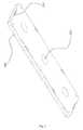
- FIG. 2schematically illustrates a magnetic plate for attracting cartridges according to the present invention.
- FIG. 3is a sectional view of a magnetic plate for attracting cartridges according to the present invention.
- FIG. 4is a sectional view of the present invention from another angle.
- the present embodimentprovides a magnetic plate for attracting cartridges.
- the magnetic platecomprises, from top to bottom, an upper cover 100 , a support frame 300 and a lower cover 200 which are connected fixedly in order.
- the support frame 300is positioned within a case formed by the upper cover 100 and the lower cover 200 .
- Magnetic componentsare mounted between the support frame 300 and the lower cover 200 .
- the magnetic componentscomprise metal members and magnetic steel members connected fixedly to the metal members.
- the metal membersare stuck on the bottom surface of the support frame 300 .
- the metal steel membersinclude first magnetic steel members 410 and second magnetic steel members 420 .
- the first magnetic steel members 410are arranged on the upper surface of the metal members and pass upwards through the support frame 300
- the second magnetic steel members 420are arranged on the lower surface of the metal members and pass through downwards through the lower cover 200 .
- the N poles of the first magnetic steel members 410 and the second magnetic steel members 420are arranged opposed to each other.
- first metal plate 510The metal member to which a first magnetic steel member 410 corresponds to is referred to as first metal plate 510
- second metal plate 520The metal member to which a second magnetic steel member 420 corresponds to is referred to as second metal plate 520 .
- a plurality of second metal plates 520are stuck on the lower surface of the support frame 300 laterally, and the second metal plates 520 are equally spaced.
- the first metal plates 510extent along the long side of the case and are stuck at the both sides of the second metal plates 520 .
- the area of contact between the first magnetic steel member 410 and the first metal plate 510is less than the area of the first metal plate 510 , and likewise the area of contact between the second magnetic steel member 420 and the second metal plate 520 is less than the area of the second metal plate 520 .
- the support frame 300is provided, at its position corresponding to the positions of the first magnetic steel members 410 , with first openings 310 for revealing portions of the first magnetic steel members 410 .
- the lower cover 200is provided, at its position corresponding to the positions of the second magnetic steel member 420 , with second openings 210 for revealing portions of the second magnetic steel members 420 .
- the first magnetic steel member 410is strip-shaped, and the second magnetic steel member 420 is circular.
- the first metal plate 510is a strip-shaped iron plate, and the second metal plate 520 is a circular iron plate.
- the first opening 310is strip-shaped, and the second opening 210 is circular.
- the strip-shaped magnetic steel members having multiple layers and sectionsare fixedly attached to the strip-shaped iron plate, and the circular magnetic steel members having multiple layers are fixedly attached to the circular iron plate.
- the areas of the strip-shaped magnetic steel members and the circular magnetic steel members that are in contact with their corresponding iron platesare less than the areas of their corresponding iron plate respectively, so that the magnetic steel members can be firmly attached to the iron plates.
- the upper cover of the magnetic plateis made of elastic plastics, so that the cartridge can be prevented from being scratched by an overly rigid upper cover when it is placed on or taken off the magnetic plate.
- the magnetic componentsare distributed symmetrically, so as to make the center of gravity of the plate located at the geometric center of the plate.
- the distribution of the magnetic componentsmay be varied depending on the requirement of the production.
- the magnetic steel memberis strip-shaped or circular.
- the magnetic plateis firmly attached to the surface of a metal panel with the aid of the circular magnetic steel members so as to reduce the area of the magnetic steel members.
- Some magnetic steel membersare configured strip-shaped for the purpose of attracting more cartridges that are arranged orderly on the upper cover.
- the strip-shaped and circular magnetic steel membersmay also be replaced by the magnetic steel members of any other shape as required.
- the magnetic platemay be fixed to a non-metal surface by riveting the lower cover, and a screwdriver is provided to the magnetic plate for taking off the magnetic plate from a metal surface conveniently.
- the metal memberis made of iron or any other material.
- the metal member and the magnetic steel memberare fixed by means of a thermally fused adhesive member, or in other common way, such as by welding or glue.
- the present embodimentutilizes two magnetic steel members which are arranged with their magnetic poles opposite to each other.
- One kind of magnetic steel membersare used for attracting the magnetic plate to the other metal surface.
- the other kind of magnetic steel membersare used for attracting cartridges.
- the arrangement of the magnetic steel memberscan realize large areas for attracting cartridges and fixing the magnetic plate.
Landscapes
- Engineering & Computer Science (AREA)
- Mechanical Engineering (AREA)
- Physics & Mathematics (AREA)
- Electromagnetism (AREA)
- Power Engineering (AREA)
- Casings For Electric Apparatus (AREA)
- Toys (AREA)
Abstract
Description
Claims (6)
Applications Claiming Priority (3)
| Application Number | Priority Date | Filing Date | Title |
|---|---|---|---|
| CN201720808724.8 | 2017-07-05 | ||
| CN201720808724.8UCN207208822U (en) | 2017-07-05 | 2017-07-05 | A kind of magnetic sheet for being used to adsorb cartridge clip |
| CN201720808724U | 2017-07-05 |
Publications (2)
| Publication Number | Publication Date |
|---|---|
| US20190009378A1 US20190009378A1 (en) | 2019-01-10 |
| US10384319B2true US10384319B2 (en) | 2019-08-20 |
Family
ID=61812435
Family Applications (1)
| Application Number | Title | Priority Date | Filing Date |
|---|---|---|---|
| US15/720,720Active2038-02-08US10384319B2 (en) | 2017-07-05 | 2017-09-29 | Magnetic plate for attracting cartridge |
Country Status (2)
| Country | Link |
|---|---|
| US (1) | US10384319B2 (en) |
| CN (1) | CN207208822U (en) |
Cited By (2)
| Publication number | Priority date | Publication date | Assignee | Title |
|---|---|---|---|---|
| US20230036310A1 (en)* | 2021-02-11 | 2023-02-02 | Amerock, LLC | Magnetic hardware display system |
| USD1047407S1 (en)* | 2021-07-14 | 2024-10-22 | Eric HERNANDEZ | Magnetic loop adapter |
Citations (11)
| Publication number | Priority date | Publication date | Assignee | Title |
|---|---|---|---|---|
| US2372685A (en)* | 1943-08-06 | 1945-04-03 | Wilbur A Schaich | Cartridge belt |
| US2435735A (en)* | 1944-01-15 | 1948-02-10 | O S Walker Co Inc | Magnetic chuck |
| US2966992A (en)* | 1957-12-23 | 1961-01-03 | American Display Company | Magnetic holder |
| US5196818A (en)* | 1992-03-30 | 1993-03-23 | Anderson Steven P | Wrist mounted magnetic holder |
| US5760668A (en)* | 1996-01-16 | 1998-06-02 | Testa; Joseph F. | Magnetic tool and object holder |
| US5904096A (en)* | 1994-04-26 | 1999-05-18 | Fawcett; Alan John | Magnetic holding device |
| US6229422B1 (en)* | 1998-04-13 | 2001-05-08 | Walker Magnetics Group, Inc. | Electrically switchable magnet system |
| US6288623B1 (en)* | 1997-06-11 | 2001-09-11 | Neuhauser, Gmbh Co. | Holding apparatus for transport of conveyed items |
| US6489871B1 (en)* | 1999-12-11 | 2002-12-03 | Simon C. Barton | Magnetic workholding device |
| US8031038B2 (en)* | 2007-02-23 | 2011-10-04 | Pascal Engineering Corporation | Magnetic fixing device |
| US9601250B2 (en)* | 2014-03-31 | 2017-03-21 | Soph International Limited | Magnetic chuck and method for producing a magnetic chuck |
- 2017
- 2017-07-05CNCN201720808724.8Upatent/CN207208822U/enactiveActive
- 2017-09-29USUS15/720,720patent/US10384319B2/enactiveActive
Patent Citations (11)
| Publication number | Priority date | Publication date | Assignee | Title |
|---|---|---|---|---|
| US2372685A (en)* | 1943-08-06 | 1945-04-03 | Wilbur A Schaich | Cartridge belt |
| US2435735A (en)* | 1944-01-15 | 1948-02-10 | O S Walker Co Inc | Magnetic chuck |
| US2966992A (en)* | 1957-12-23 | 1961-01-03 | American Display Company | Magnetic holder |
| US5196818A (en)* | 1992-03-30 | 1993-03-23 | Anderson Steven P | Wrist mounted magnetic holder |
| US5904096A (en)* | 1994-04-26 | 1999-05-18 | Fawcett; Alan John | Magnetic holding device |
| US5760668A (en)* | 1996-01-16 | 1998-06-02 | Testa; Joseph F. | Magnetic tool and object holder |
| US6288623B1 (en)* | 1997-06-11 | 2001-09-11 | Neuhauser, Gmbh Co. | Holding apparatus for transport of conveyed items |
| US6229422B1 (en)* | 1998-04-13 | 2001-05-08 | Walker Magnetics Group, Inc. | Electrically switchable magnet system |
| US6489871B1 (en)* | 1999-12-11 | 2002-12-03 | Simon C. Barton | Magnetic workholding device |
| US8031038B2 (en)* | 2007-02-23 | 2011-10-04 | Pascal Engineering Corporation | Magnetic fixing device |
| US9601250B2 (en)* | 2014-03-31 | 2017-03-21 | Soph International Limited | Magnetic chuck and method for producing a magnetic chuck |
Cited By (2)
| Publication number | Priority date | Publication date | Assignee | Title |
|---|---|---|---|---|
| US20230036310A1 (en)* | 2021-02-11 | 2023-02-02 | Amerock, LLC | Magnetic hardware display system |
| USD1047407S1 (en)* | 2021-07-14 | 2024-10-22 | Eric HERNANDEZ | Magnetic loop adapter |
Also Published As
| Publication number | Publication date |
|---|---|
| CN207208822U (en) | 2018-04-10 |
| US20190009378A1 (en) | 2019-01-10 |
Similar Documents
| Publication | Publication Date | Title |
|---|---|---|
| US9969450B1 (en) | Bicycle cellular phone holder structure | |
| US10384319B2 (en) | Magnetic plate for attracting cartridge | |
| US9057479B2 (en) | Wall-mounted aiding mechanism and wall-mounted device | |
| WO2011148450A1 (en) | Substrate storage container | |
| KR102109465B1 (en) | Organic light-emitting display device | |
| US10475680B2 (en) | Wafer shipping box and a lower retaining member thereof | |
| US20170144826A1 (en) | Packing box for liquid crystal glass panel | |
| WO2017146174A1 (en) | Cell device, cell unit, and cell device installation method | |
| US8320065B2 (en) | Lens driving device | |
| US3153177A (en) | Magnetic holder for paper clips | |
| US20220355968A1 (en) | Tray for loading battery cap | |
| US20160343503A1 (en) | Transformer | |
| US20120273436A1 (en) | Data center container | |
| US7775362B2 (en) | Substrate accommodating apparatus with loop-shaped binding member | |
| KR101426898B1 (en) | Tray assembly for display pannel transporting | |
| KR101104849B1 (en) | Display Unit Carrier | |
| US8289636B2 (en) | Auto-focus lens module | |
| JP3195120U (en) | Roll shipping box | |
| TW201929293A (en) | Battery module | |
| JP2018145451A (en) | Vapor deposition pattern forming method, vapor deposition pattern forming apparatus, vapor deposition mask with frame, and frame | |
| JP5963661B2 (en) | Wafer frame cassette | |
| JP4621988B2 (en) | Cassette for semiconductor wafer | |
| US20170166353A1 (en) | Organizer case | |
| US9547149B2 (en) | Assembling device for guide pole of camera actuator | |
| CN109987338B (en) | Packing case (food) |
Legal Events
| Date | Code | Title | Description |
|---|---|---|---|
| AS | Assignment | Owner name:NINGBO NEWLAND MAGNET INDUSTRY CORPORATION LIMITED Free format text:ASSIGNMENT OF ASSIGNORS INTEREST;ASSIGNOR:CHENG, TINGHAI;REEL/FRAME:044071/0307 Effective date:20170927 | |
| FEPP | Fee payment procedure | Free format text:ENTITY STATUS SET TO UNDISCOUNTED (ORIGINAL EVENT CODE: BIG.); ENTITY STATUS OF PATENT OWNER: SMALL ENTITY | |
| FEPP | Fee payment procedure | Free format text:ENTITY STATUS SET TO SMALL (ORIGINAL EVENT CODE: SMAL); ENTITY STATUS OF PATENT OWNER: SMALL ENTITY | |
| STPP | Information on status: patent application and granting procedure in general | Free format text:DOCKETED NEW CASE - READY FOR EXAMINATION | |
| STPP | Information on status: patent application and granting procedure in general | Free format text:NOTICE OF ALLOWANCE MAILED -- APPLICATION RECEIVED IN OFFICE OF PUBLICATIONS | |
| STPP | Information on status: patent application and granting procedure in general | Free format text:PUBLICATIONS -- ISSUE FEE PAYMENT VERIFIED | |
| STCF | Information on status: patent grant | Free format text:PATENTED CASE | |
| MAFP | Maintenance fee payment | Free format text:PAYMENT OF MAINTENANCE FEE, 4TH YR, SMALL ENTITY (ORIGINAL EVENT CODE: M2551); ENTITY STATUS OF PATENT OWNER: SMALL ENTITY Year of fee payment:4 |