US10384165B1 - Solar desalination system - Google Patents
Solar desalination systemDownload PDFInfo
- Publication number
- US10384165B1 US10384165B1US16/178,398US201816178398AUS10384165B1US 10384165 B1US10384165 B1US 10384165B1US 201816178398 AUS201816178398 AUS 201816178398AUS 10384165 B1US10384165 B1US 10384165B1
- Authority
- US
- United States
- Prior art keywords
- condensate
- seawater
- absorber base
- chamber
- chambers
- Prior art date
- Legal status (The legal status is an assumption and is not a legal conclusion. Google has not performed a legal analysis and makes no representation as to the accuracy of the status listed.)
- Active - Reinstated
Links
Images


Classifications
- B—PERFORMING OPERATIONS; TRANSPORTING
- B01—PHYSICAL OR CHEMICAL PROCESSES OR APPARATUS IN GENERAL
- B01D—SEPARATION
- B01D61/00—Processes of separation using semi-permeable membranes, e.g. dialysis, osmosis or ultrafiltration; Apparatus, accessories or auxiliary operations specially adapted therefor
- B01D61/36—Pervaporation; Membrane distillation; Liquid permeation
- B01D61/364—Membrane distillation
- B01D61/3641—Membrane distillation comprising multiple membrane distillation steps
- B—PERFORMING OPERATIONS; TRANSPORTING
- B01—PHYSICAL OR CHEMICAL PROCESSES OR APPARATUS IN GENERAL
- B01D—SEPARATION
- B01D61/00—Processes of separation using semi-permeable membranes, e.g. dialysis, osmosis or ultrafiltration; Apparatus, accessories or auxiliary operations specially adapted therefor
- B01D61/36—Pervaporation; Membrane distillation; Liquid permeation
- B01D61/366—Apparatus therefor
- B—PERFORMING OPERATIONS; TRANSPORTING
- B01—PHYSICAL OR CHEMICAL PROCESSES OR APPARATUS IN GENERAL
- B01D—SEPARATION
- B01D61/00—Processes of separation using semi-permeable membranes, e.g. dialysis, osmosis or ultrafiltration; Apparatus, accessories or auxiliary operations specially adapted therefor
- B01D61/36—Pervaporation; Membrane distillation; Liquid permeation
- B01D61/368—Accessories; Auxiliary operations
- B—PERFORMING OPERATIONS; TRANSPORTING
- B01—PHYSICAL OR CHEMICAL PROCESSES OR APPARATUS IN GENERAL
- B01D—SEPARATION
- B01D69/00—Semi-permeable membranes for separation processes or apparatus characterised by their form, structure or properties; Manufacturing processes specially adapted therefor
- B01D69/02—Semi-permeable membranes for separation processes or apparatus characterised by their form, structure or properties; Manufacturing processes specially adapted therefor characterised by their properties
- C—CHEMISTRY; METALLURGY
- C02—TREATMENT OF WATER, WASTE WATER, SEWAGE, OR SLUDGE
- C02F—TREATMENT OF WATER, WASTE WATER, SEWAGE, OR SLUDGE
- C02F1/00—Treatment of water, waste water, or sewage
- C02F1/44—Treatment of water, waste water, or sewage by dialysis, osmosis or reverse osmosis
- C02F1/447—Treatment of water, waste water, or sewage by dialysis, osmosis or reverse osmosis by membrane distillation
- B—PERFORMING OPERATIONS; TRANSPORTING
- B01—PHYSICAL OR CHEMICAL PROCESSES OR APPARATUS IN GENERAL
- B01D—SEPARATION
- B01D2313/00—Details relating to membrane modules or apparatus
- B01D2313/20—Specific housing
- B01D2313/205—Specific housing characterised by the shape
- B—PERFORMING OPERATIONS; TRANSPORTING
- B01—PHYSICAL OR CHEMICAL PROCESSES OR APPARATUS IN GENERAL
- B01D—SEPARATION
- B01D2313/00—Details relating to membrane modules or apparatus
- B01D2313/20—Specific housing
- B01D2313/206—Specific housing characterised by the material
- B—PERFORMING OPERATIONS; TRANSPORTING
- B01—PHYSICAL OR CHEMICAL PROCESSES OR APPARATUS IN GENERAL
- B01D—SEPARATION
- B01D2313/00—Details relating to membrane modules or apparatus
- B01D2313/22—Cooling or heating elements
- B—PERFORMING OPERATIONS; TRANSPORTING
- B01—PHYSICAL OR CHEMICAL PROCESSES OR APPARATUS IN GENERAL
- B01D—SEPARATION
- B01D2313/00—Details relating to membrane modules or apparatus
- B01D2313/22—Cooling or heating elements
- B01D2313/221—Heat exchangers
- B—PERFORMING OPERATIONS; TRANSPORTING
- B01—PHYSICAL OR CHEMICAL PROCESSES OR APPARATUS IN GENERAL
- B01D—SEPARATION
- B01D2313/00—Details relating to membrane modules or apparatus
- B01D2313/24—Specific pressurizing or depressurizing means
- B01D2313/243—Pumps
- B—PERFORMING OPERATIONS; TRANSPORTING
- B01—PHYSICAL OR CHEMICAL PROCESSES OR APPARATUS IN GENERAL
- B01D—SEPARATION
- B01D2313/00—Details relating to membrane modules or apparatus
- B01D2313/36—Energy sources
- B01D2313/367—Renewable energy sources, e.g. wind or solar sources
- B—PERFORMING OPERATIONS; TRANSPORTING
- B01—PHYSICAL OR CHEMICAL PROCESSES OR APPARATUS IN GENERAL
- B01D—SEPARATION
- B01D2313/00—Details relating to membrane modules or apparatus
- B01D2313/50—Specific extra tanks
- B—PERFORMING OPERATIONS; TRANSPORTING
- B01—PHYSICAL OR CHEMICAL PROCESSES OR APPARATUS IN GENERAL
- B01D—SEPARATION
- B01D2313/00—Details relating to membrane modules or apparatus
- B01D2313/50—Specific extra tanks
- B01D2313/501—Permeate storage tanks
- B—PERFORMING OPERATIONS; TRANSPORTING
- B01—PHYSICAL OR CHEMICAL PROCESSES OR APPARATUS IN GENERAL
- B01D—SEPARATION
- B01D2325/00—Details relating to properties of membranes
- B01D2325/38—Hydrophobic membranes
- C—CHEMISTRY; METALLURGY
- C02—TREATMENT OF WATER, WASTE WATER, SEWAGE, OR SLUDGE
- C02F—TREATMENT OF WATER, WASTE WATER, SEWAGE, OR SLUDGE
- C02F2103/00—Nature of the water, waste water, sewage or sludge to be treated
- C02F2103/08—Seawater, e.g. for desalination
- C—CHEMISTRY; METALLURGY
- C02—TREATMENT OF WATER, WASTE WATER, SEWAGE, OR SLUDGE
- C02F—TREATMENT OF WATER, WASTE WATER, SEWAGE, OR SLUDGE
- C02F2201/00—Apparatus for treatment of water, waste water or sewage
- C02F2201/009—Apparatus with independent power supply, e.g. solar cells, windpower or fuel cells
- Y—GENERAL TAGGING OF NEW TECHNOLOGICAL DEVELOPMENTS; GENERAL TAGGING OF CROSS-SECTIONAL TECHNOLOGIES SPANNING OVER SEVERAL SECTIONS OF THE IPC; TECHNICAL SUBJECTS COVERED BY FORMER USPC CROSS-REFERENCE ART COLLECTIONS [XRACs] AND DIGESTS
- Y02—TECHNOLOGIES OR APPLICATIONS FOR MITIGATION OR ADAPTATION AGAINST CLIMATE CHANGE
- Y02A—TECHNOLOGIES FOR ADAPTATION TO CLIMATE CHANGE
- Y02A20/00—Water conservation; Efficient water supply; Efficient water use
- Y02A20/124—Water desalination
- Y02A20/131—Reverse-osmosis
- Y—GENERAL TAGGING OF NEW TECHNOLOGICAL DEVELOPMENTS; GENERAL TAGGING OF CROSS-SECTIONAL TECHNOLOGIES SPANNING OVER SEVERAL SECTIONS OF THE IPC; TECHNICAL SUBJECTS COVERED BY FORMER USPC CROSS-REFERENCE ART COLLECTIONS [XRACs] AND DIGESTS
- Y02—TECHNOLOGIES OR APPLICATIONS FOR MITIGATION OR ADAPTATION AGAINST CLIMATE CHANGE
- Y02A—TECHNOLOGIES FOR ADAPTATION TO CLIMATE CHANGE
- Y02A20/00—Water conservation; Efficient water supply; Efficient water use
- Y02A20/20—Controlling water pollution; Waste water treatment
- Y02A20/208—Off-grid powered water treatment
- Y02A20/212—Solar-powered wastewater sewage treatment, e.g. spray evaporation
Definitions
- the disclosure of the present patent applicationrelates to desalination of salt water, and particularly to a solar desalination system combining a Fresnel solar concentrator with a desalination chamber that uses membrane distillation.
- Membrane distillationis a thermally driven separation process in which the separation of salt from water is enabled by phase change.
- a hydrophobic membraneforms a barrier for the liquid phase, allowing the vapor phase (e.g., water vapor) to pass through the membrane's pores.
- the driving force of the processis given by a partial vapor pressure difference, commonly triggered by a temperature difference.
- Such membrane distillation processescan be used for desalination, and it would be desirable to be able to create the temperature difference through the use of renewable solar energy.
- a solar desalination systemsolving the aforementioned problems is desired.
- the solar desalination systemuses solar energy to provide heat for membrane distillation of seawater.
- the solar desalination systemincludes a desalination chamber suspended above a linear Fresnel reflector array.
- the desalination chamberincludes an upper wall, at least one sidewall and a lower wall, which define a fluid-tight hollow housing.
- the lower wallhas an upper surface and a lower surface, and further includes a thermally conductive central portion defining an absorber base, and first and second thermally insulating portions above and below the absorber base.
- the absorber baseis positioned at a focal line of the linear Fresnel reflector array.
- the at least one sidewallhas opposed upper and lower edges, such that the lower edge is secured to the upper surface of the lower wall and the upper edge is secured to the upper wall.
- the at least one sidewallhas an inlet port and first and second condensate retrieval ports.
- First and second hydrophobic membranesare mounted within the hollow housing, so that a central chamber is defined between the first and second hydrophobic membranes, and first and second condensate chambers are respectively defined between the at least one sidewall and the first and second hydrophobic membranes.
- the inlet portis in fluid communication with the central chamber, and the first and second condensate retrieval ports are in respective fluid communication with the first and second condensate chambers.
- the central chamberis positioned above the absorber base, and the first and second condensate chambers are respectively positioned above the first and second insulating portions.
- a seawater conduithas an outlet in fluid communication with the central chamber through the inlet port, and a condensate retrieval conduit has first and second inlets respectively in fluid communication with the first and second condensate chambers through the first and second condensate retrieval ports, respectively.
- a closed, optically transparent housingmay be secured to and cover a lower surface of the absorber base.
- a vacuummay be formed between the closed, optically transparent housing and the lower surface of the absorber base.
- the seawater conduitdelivers seawater to the central chamber, where the seawater is heated by the absorber base, which absorbed solar energy from the Fresnel reflectors, to heat water without boiling it.
- Fresh water at ambient temperatureis circulated inside the condensate chambers.
- the temperature difference across the membranecauses a vapor partial pressure difference with high pressure at the heated seawater inside the central chamber.
- This pressure differencecauses the formed water vapor to pass through the first and second hydrophobic membranes into the first and second condensate chambers, respectively, where the water vapor cools to form pure water condensate.
- the pure water condensateis then extracted from the first and second condensate chambers by the first and second inlets, respectively, of the condensate retrieval conduit.
- the seawatermay be initially held in a seawater tank.
- a first pumpis provided for selectively transferring the seawater from the seawater tank to the central chamber through the seawater conduit.
- the pure water condensatemay be received by and stored within a pure water tank.
- a second pumpselectively transfers the pure water condensate to the pure water tank through the condensate retrieval conduit.
- FIG. 1is a schematic diagram of a solar desalination system.
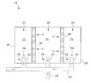
- FIG. 2is a schematic diagram of the desalination chamber of the solar desalination system of FIG. 1 , as seen from the front.
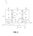
- FIG. 3is a schematic diagram of the desalination chamber of FIG. 2 , as seen from the top.
- FIG. 4is a detailed front view of the desalination chamber of FIG. 2 .
- the solar desalination system 10uses solar energy to provide heat for membrane distillation of seawater.
- the solar desalination system 10includes a desalination chamber 14 suspended above a linear Fresnel reflector array 20 .
- the desalination chamber 14includes an upper wall 42 , at least one sidewall 38 and a lower wall 34 , which define a fluid-tight hollow housing 60 .
- the lower wall 34has an upper surface 43 and a lower surface 44 .
- the lower wall 34includes a thermally conductive central portion defining an absorber base 70 , and first and second thermally insulation sections or portions 72 , 74 extending on opposite sides of the absorber base 70 .
- the absorber base 70is positioned at a focal line of the linear Fresnel reflector array 20 .
- the absorber basemay, e.g., be made from a metal having high thermal conductivity, such as copper or aluminum, and may be painted black or a dark color to absorb heat from the Fresnel mirrors of the reflector array 20 , which will readily be transferred to and absorbed by water in the desalination chamber 14 .
- the lower wall 34 and the upper wall 42are shown as being rectangular, and the at least one sidewall 38 is shown as four corresponding walls, defining a rectangular interior. It should be understood that the overall configuration and relative dimensions of the lower wall 34 , upper wall 42 and the at least one sidewall 38 are shown for exemplary purposes only.
- the desalination chamber 14is shown as being open. It should be understood that this open configuration is shown for purposes of clarity and illustration only. As shown in FIG. 4 , the desalination chamber 14 (in the rectangular example described above) is enclosed, defining a fluid-tight chamber.
- the at least one sidewall 38has opposed upper and lower edges, so that the lower edge is secured to the upper surface 43 of the lower wall 34 and the upper edge is secured to the upper wall 42 .
- the at least one sidewall 38has an inlet port 56 and first and second condensate retrieval ports 58 , 62 , respectively.
- First and second hydrophobic membranes 46 , 48are mounted within the hollow housing 60 , such that a central chamber 50 is defined therebetween, and first and second condensate chambers 52 , 54 are respectively defined between the at least one sidewall 38 and the first and second hydrophobic membranes 46 , 48 .
- the inlet port 56is in fluid communication with the central chamber 50 , and the first and second condensate retrieval ports 58 , 62 , are in fluid communication with the first and second condensate chambers 52 , 54 , respectively.
- the central chamber 50is positioned above the absorber base 50 , and the first and second condensate chambers 52 , 54 are respectively positioned above the first and second insulation portions 72 , 74 .
- the absorber base 70may be made from any suitable type of metal or material having a high degree of thermal conductivity and a high melting temperature.
- the at least one sidewall 38 , the upper wall 42 and the first and second insulating portions 72 , 74may be made from any suitable type of material having a high degree of thermal insulation and/or may be covered by an additional layer of thermal insulation material.
- a seawater conduit 26has an outlet 30 in fluid communication with the central chamber 50 through the inlet port 56 .
- a condensate retrieval conduit 28has first and second inlets 32 , 40 , respectively, in fluid communication with the first and second condensate chambers 52 , 54 through the first and second condensate retrieval ports 58 , 62 , respectively.
- a closed, optically transparent housing 36may be secured to and cover the lower surface 76 of the absorber base 70 .
- a vacuummay be formed between the closed, optically transparent housing 36 and the lower surface 76 of the absorber base 70 .
- the closed, optically transparent housing 36is provided to prevent heat loss from the absorber base 34 through convective heat transfer with the ambient environment.
- the vacuumis formed within the closed, optically transparent housing 36 to further enhance the thermal insulation.
- the optically transparent housing 36is shown as being open. It should be understood that this open configuration is shown for purposes of clarity and illustration only.
- FIG. 4shows an additional front wall 51 , it being understood that there should be an additional rear wall, thus forming a closed housing.
- the closed, optically transparent housing 36allows the focused solar radiation S to reach the absorber base 34 without environmental air extracting heat therefrom through convective heat transfer.
- the seawater conduit 26delivers seawater to the central chamber 50 , where the seawater is heated by the absorber base 70 .
- the absorber base 70is positioned above the focal line of the linear Fresnel reflector array 20 .
- FIG. 1it should be understood that the linear Fresnel reflector array 20 , which is used to focus solar radiation S on absorber base 70 , is shown in a simplified manner for purposes of illustration and clarity.
- the desalination chamber 14is supported by any suitable type of support structure 12 , such that absorber base 70 is located at the focal line of the linear Fresnel reflector array 20 .
- the absorber base 70is thermally conductive, thus allowing heat transfer to the seawater in the central chamber 50 .
- the water partial pressureincreases until the vapor pressure across the membrane causes the water vapor to form at the hot surface of the membrane and pass through the first and second hydrophobic membranes 46 , 48 into the first and second condensate chambers 52 , 54 , where the water vapor V cools to form pure water condensate PW.
- first and second thermally insulating portions 72 , 74are disposed on opposite sides of the absorber base 70 such that the first and second condensate chambers 52 , 54 are positioned above the first and second thermally insulating portions 72 , 74 , respectively, which form the floors of the chambers 52 , 54 .
- the heat transfer between the absorber base 70 and the interior of housing 60is limited to the central chamber 50 , the first and second thermally insulation portions 72 , 74 maintaining the first and second condensate chambers 52 , 54 , respectively, at a temperature below the vaporization point of water.
- the pure water condensate PWis then extracted from the first and second condensate chambers 52 , 54 by the first and second inlets 32 , 40 , respectively, of the condensate retrieval conduit 28 .
- the seawatermay be initially held in a seawater tank 16 .
- a first pump 22is provided for selectively transferring the seawater from the seawater tank 16 to the central chamber 50 through the seawater conduit 26 .
- the pure water condensate PWmay be received by and stored within a pure water tank 18 .
- a second pump 24selectively transfers the pure water condensate PW to the pure water tank 18 through the condensate retrieval conduit 28 .
- the temperature of the seawater within the central chamber 50may be maintained at slightly above 100° C.
- the temperature within the condensate retrieval chambers 52 , 54is below 100° C., and this temperature differential creates a corresponding differential in water vapor pressure across each of membranes 46 , 48 .
- This pressure differencecauses the water vapor V to pass through membranes 46 , 48 into, respectively, the first and second condensate retrieval chambers 52 , 54 .
Landscapes
- Engineering & Computer Science (AREA)
- Water Supply & Treatment (AREA)
- Chemical & Material Sciences (AREA)
- Chemical Kinetics & Catalysis (AREA)
- Life Sciences & Earth Sciences (AREA)
- Hydrology & Water Resources (AREA)
- Environmental & Geological Engineering (AREA)
- Organic Chemistry (AREA)
- Heat Treatment Of Water, Waste Water Or Sewage (AREA)
Abstract
Description
Claims (9)
Priority Applications (2)
| Application Number | Priority Date | Filing Date | Title |
|---|---|---|---|
| US16/178,398US10384165B1 (en) | 2018-11-01 | 2018-11-01 | Solar desalination system |
| SA119410149ASA119410149B1 (en) | 2018-11-01 | 2019-10-28 | Solar Desalination System |
Applications Claiming Priority (1)
| Application Number | Priority Date | Filing Date | Title |
|---|---|---|---|
| US16/178,398US10384165B1 (en) | 2018-11-01 | 2018-11-01 | Solar desalination system |
Publications (1)
| Publication Number | Publication Date |
|---|---|
| US10384165B1true US10384165B1 (en) | 2019-08-20 |
Family
ID=67620861
Family Applications (1)
| Application Number | Title | Priority Date | Filing Date |
|---|---|---|---|
| US16/178,398Active - ReinstatedUS10384165B1 (en) | 2018-11-01 | 2018-11-01 | Solar desalination system |
Country Status (2)
| Country | Link |
|---|---|
| US (1) | US10384165B1 (en) |
| SA (1) | SA119410149B1 (en) |
Cited By (5)
| Publication number | Priority date | Publication date | Assignee | Title |
|---|---|---|---|---|
| US11502323B1 (en) | 2022-05-09 | 2022-11-15 | Rahul S Nana | Reverse electrodialysis cell and methods of use thereof |
| US11502322B1 (en) | 2022-05-09 | 2022-11-15 | Rahul S Nana | Reverse electrodialysis cell with heat pump |
| US11855324B1 (en) | 2022-11-15 | 2023-12-26 | Rahul S. Nana | Reverse electrodialysis or pressure-retarded osmosis cell with heat pump |
| US12040517B2 (en) | 2022-11-15 | 2024-07-16 | Rahul S. Nana | Reverse electrodialysis or pressure-retarded osmosis cell and methods of use thereof |
| US12341228B2 (en) | 2022-11-15 | 2025-06-24 | Rahul S. Nana | Reverse electrodialysis or pressure-retarded osmosis cell and methods of use thereof |
Citations (11)
| Publication number | Priority date | Publication date | Assignee | Title |
|---|---|---|---|---|
| EP0039197A1 (en)* | 1980-04-25 | 1981-11-04 | W.L. GORE & ASSOCIATES, INC. | Distillation apparatus |
| US4383891A (en)* | 1979-08-28 | 1983-05-17 | Spie-Batignolles | Device for desalting brackish water, and a conditioning method and device relating to said desalting device |
| KR100905944B1 (en) | 2009-01-06 | 2009-07-06 | 뉴엔텍(주) | Seawater Desalination System Using Photovoltaic Composite Module |
| US20110198208A1 (en) | 2008-11-07 | 2011-08-18 | Deutsches Zentrum Fur Luft-Und Raumfahrt E.V. | Method for desalinating water containing salt |
| US20120260907A1 (en) | 2011-04-15 | 2012-10-18 | King Saud University | Solar Heating Apparatus and Methods |
| US20130277199A1 (en)* | 2012-04-18 | 2013-10-24 | Massachusetts Institute Of Technology | Solar-Driven Air Gap Membrane Distillation System |
| US20140290247A1 (en) | 2013-03-28 | 2014-10-02 | Hitachi, Ltd. | Integrative System of Concentrating Solar Power Plant and Desalineation Plant |
| US20150353379A1 (en)* | 2008-02-22 | 2015-12-10 | James Weifu Lee | Photovoltaic panel-interfaced solar-greenhouse distillation systems |
| CN106927531A (en) | 2017-03-20 | 2017-07-07 | 北京理工大学 | Half immersion solar seawater desalination system |
| US20170204838A1 (en) | 2009-12-07 | 2017-07-20 | Electrotherm Solar Corporation | Concentrated Photovoltaic and Thermal Solar Energy Collector |
| CN107963686A (en) | 2018-01-10 | 2018-04-27 | 华北电力大学 | Solar energy based on high power concentrator-dilatation membrane distillation method for treating desulfurized wastewater |
- 2018
- 2018-11-01USUS16/178,398patent/US10384165B1/enactiveActive - Reinstated
- 2019
- 2019-10-28SASA119410149Apatent/SA119410149B1/enunknown
Patent Citations (11)
| Publication number | Priority date | Publication date | Assignee | Title |
|---|---|---|---|---|
| US4383891A (en)* | 1979-08-28 | 1983-05-17 | Spie-Batignolles | Device for desalting brackish water, and a conditioning method and device relating to said desalting device |
| EP0039197A1 (en)* | 1980-04-25 | 1981-11-04 | W.L. GORE & ASSOCIATES, INC. | Distillation apparatus |
| US20150353379A1 (en)* | 2008-02-22 | 2015-12-10 | James Weifu Lee | Photovoltaic panel-interfaced solar-greenhouse distillation systems |
| US20110198208A1 (en) | 2008-11-07 | 2011-08-18 | Deutsches Zentrum Fur Luft-Und Raumfahrt E.V. | Method for desalinating water containing salt |
| KR100905944B1 (en) | 2009-01-06 | 2009-07-06 | 뉴엔텍(주) | Seawater Desalination System Using Photovoltaic Composite Module |
| US20170204838A1 (en) | 2009-12-07 | 2017-07-20 | Electrotherm Solar Corporation | Concentrated Photovoltaic and Thermal Solar Energy Collector |
| US20120260907A1 (en) | 2011-04-15 | 2012-10-18 | King Saud University | Solar Heating Apparatus and Methods |
| US20130277199A1 (en)* | 2012-04-18 | 2013-10-24 | Massachusetts Institute Of Technology | Solar-Driven Air Gap Membrane Distillation System |
| US20140290247A1 (en) | 2013-03-28 | 2014-10-02 | Hitachi, Ltd. | Integrative System of Concentrating Solar Power Plant and Desalineation Plant |
| CN106927531A (en) | 2017-03-20 | 2017-07-07 | 北京理工大学 | Half immersion solar seawater desalination system |
| CN107963686A (en) | 2018-01-10 | 2018-04-27 | 华北电力大学 | Solar energy based on high power concentrator-dilatation membrane distillation method for treating desulfurized wastewater |
Non-Patent Citations (1)
| Title |
|---|
| Trieb et al., "Concentrating solar power for seawater thermal desalination," Twelfth International Water Technology Conference, 2008 Alexandria, Egypt. |
Cited By (10)
| Publication number | Priority date | Publication date | Assignee | Title |
|---|---|---|---|---|
| US11502323B1 (en) | 2022-05-09 | 2022-11-15 | Rahul S Nana | Reverse electrodialysis cell and methods of use thereof |
| US11502322B1 (en) | 2022-05-09 | 2022-11-15 | Rahul S Nana | Reverse electrodialysis cell with heat pump |
| US11563229B1 (en) | 2022-05-09 | 2023-01-24 | Rahul S Nana | Reverse electrodialysis cell with heat pump |
| US11611099B1 (en) | 2022-05-09 | 2023-03-21 | Rahul S Nana | Reverse electrodialysis cell and methods of use thereof |
| US11699803B1 (en) | 2022-05-09 | 2023-07-11 | Rahul S Nana | Reverse electrodialysis cell with heat pump |
| US12107308B2 (en) | 2022-05-09 | 2024-10-01 | Rahul S Nana | Reverse electrodialysis cell and methods of use thereof |
| US11855324B1 (en) | 2022-11-15 | 2023-12-26 | Rahul S. Nana | Reverse electrodialysis or pressure-retarded osmosis cell with heat pump |
| US12040517B2 (en) | 2022-11-15 | 2024-07-16 | Rahul S. Nana | Reverse electrodialysis or pressure-retarded osmosis cell and methods of use thereof |
| US12341228B2 (en) | 2022-11-15 | 2025-06-24 | Rahul S. Nana | Reverse electrodialysis or pressure-retarded osmosis cell and methods of use thereof |
| US12374711B2 (en) | 2022-11-15 | 2025-07-29 | Rahul S. Nana | Reverse electrodialysis or pressure-retarded osmosis cell with heat pump |
Also Published As
| Publication number | Publication date |
|---|---|
| SA119410149B1 (en) | 2022-07-28 |
Similar Documents
| Publication | Publication Date | Title |
|---|---|---|
| US10384165B1 (en) | Solar desalination system | |
| US10183233B1 (en) | Solar desalination system | |
| US10233095B1 (en) | Solar desalination and power generating system | |
| Xu et al. | All-day freshwater harvesting through combined solar-driven interfacial desalination and passive radiative cooling | |
| Xue et al. | Highly efficient water harvesting with optimized solar thermal membrane distillation device | |
| Huang et al. | Coupling photothermal and Joule-heating conversion for self-heating membrane distillation enhancement | |
| US9796602B2 (en) | Solar water purifier | |
| US11312640B2 (en) | Method and device for enhanced water production in solar-powered devices | |
| Ma et al. | Distributed vacuum membrane distillation driven by direct-solar heating at ultra-low temperature | |
| Fang et al. | Application design and assessment of a novel small-decentralized solar distillation device based on energy, exergy, exergoeconomic, and enviroeconomic parameters | |
| CN113896269A (en) | A high-efficiency solar-powered seawater desalination device based on interfacial evaporation | |
| CN110291044A (en) | System and method for solar vapor evaporation and condensation | |
| Wang et al. | Conical solar-thermo-radiative evaporator for sustainable desalination and salt recovery | |
| Hooshmand et al. | An experimental study of a solar hybrid system to produce freshwater from waste heat of photovoltaic module by using thermosyphon heat pipes | |
| Deniz | Solar-powered desalination | |
| Chang et al. | Salt-rejecting rGO-coated melamine foams for high-efficiency solar desalination | |
| US10696565B2 (en) | Method and device for treating a fluid | |
| JP2013066881A (en) | Membrane distillation solar water production system | |
| Lindblom | Solar thermal technologies for seawater desalination: state of the art | |
| US4233153A (en) | Continuous method and apparatus for separating solvent from solute | |
| CN213679910U (en) | Desalination device combining sea water waste heat utilization and interface evaporation | |
| KR101543426B1 (en) | Water Treatment Apparatus using Membrane Distillation Method | |
| Hashim | A new design of a single slop double-basin solar still (SSDBS) | |
| Saleem et al. | Productivity comparison of conventional and single slope solar still with internal reflectors: an overview | |
| JPS62140691A (en) | Desalting device for sea water by utilizing solar heat |
Legal Events
| Date | Code | Title | Description |
|---|---|---|---|
| FEPP | Fee payment procedure | Free format text:ENTITY STATUS SET TO UNDISCOUNTED (ORIGINAL EVENT CODE: BIG.); ENTITY STATUS OF PATENT OWNER: SMALL ENTITY | |
| FEPP | Fee payment procedure | Free format text:ENTITY STATUS SET TO SMALL (ORIGINAL EVENT CODE: SMAL); ENTITY STATUS OF PATENT OWNER: SMALL ENTITY | |
| STCF | Information on status: patent grant | Free format text:PATENTED CASE | |
| FEPP | Fee payment procedure | Free format text:MAINTENANCE FEE REMINDER MAILED (ORIGINAL EVENT CODE: REM.); ENTITY STATUS OF PATENT OWNER: SMALL ENTITY | |
| LAPS | Lapse for failure to pay maintenance fees | Free format text:PATENT EXPIRED FOR FAILURE TO PAY MAINTENANCE FEES (ORIGINAL EVENT CODE: EXP.); ENTITY STATUS OF PATENT OWNER: SMALL ENTITY | |
| STCH | Information on status: patent discontinuation | Free format text:PATENT EXPIRED DUE TO NONPAYMENT OF MAINTENANCE FEES UNDER 37 CFR 1.362 | |
| FP | Lapsed due to failure to pay maintenance fee | Effective date:20230820 | |
| PRDP | Patent reinstated due to the acceptance of a late maintenance fee | Effective date:20250808 | |
| FEPP | Fee payment procedure | Free format text:SURCHARGE, PETITION TO ACCEPT PYMT AFTER EXP, UNINTENTIONAL. (ORIGINAL EVENT CODE: M2558); ENTITY STATUS OF PATENT OWNER: SMALL ENTITY Free format text:PETITION RELATED TO MAINTENANCE FEES GRANTED (ORIGINAL EVENT CODE: PMFG); ENTITY STATUS OF PATENT OWNER: SMALL ENTITY Free format text:PETITION RELATED TO MAINTENANCE FEES FILED (ORIGINAL EVENT CODE: PMFP); ENTITY STATUS OF PATENT OWNER: SMALL ENTITY | |
| MAFP | Maintenance fee payment | Free format text:PAYMENT OF MAINTENANCE FEE, 4TH YR, SMALL ENTITY (ORIGINAL EVENT CODE: M2551); ENTITY STATUS OF PATENT OWNER: SMALL ENTITY Year of fee payment:4 | |
| STCF | Information on status: patent grant | Free format text:PATENTED CASE |