US10383741B2 - Expandable spinal interbody assembly - Google Patents
Expandable spinal interbody assemblyDownload PDFInfo
- Publication number
- US10383741B2 US10383741B2US15/497,011US201715497011AUS10383741B2US 10383741 B2US10383741 B2US 10383741B2US 201715497011 AUS201715497011 AUS 201715497011AUS 10383741 B2US10383741 B2US 10383741B2
- Authority
- US
- United States
- Prior art keywords
- support assembly
- control member
- implant
- control
- bottom support
- Prior art date
- Legal status (The legal status is an assumption and is not a legal conclusion. Google has not performed a legal analysis and makes no representation as to the accuracy of the status listed.)
- Active, expires
Links
- 239000007943implantSubstances0.000claimsabstractdescription234
- 230000033001locomotionEffects0.000claimsabstractdescription28
- 210000000988bone and boneAnatomy0.000claimsabstractdescription27
- 230000001154acute effectEffects0.000claimsabstractdescription3
- 230000000712assemblyEffects0.000claimsdescription9
- 238000000429assemblyMethods0.000claimsdescription9
- 238000000034methodMethods0.000claimsdescription5
- 239000012530fluidSubstances0.000description13
- 239000000463materialSubstances0.000description12
- 238000004891communicationMethods0.000description7
- 230000014759maintenance of locationEffects0.000description6
- 238000003780insertionMethods0.000description5
- 230000037431insertionEffects0.000description5
- 230000008602contractionEffects0.000description4
- 238000006073displacement reactionMethods0.000description4
- 230000004927fusionEffects0.000description4
- 230000007246mechanismEffects0.000description4
- 230000003068static effectEffects0.000description4
- 208000000875Spinal CurvaturesDiseases0.000description3
- 239000000560biocompatible materialSubstances0.000description3
- 230000008468bone growthEffects0.000description3
- 239000002131composite materialSubstances0.000description3
- 239000002184metalSubstances0.000description3
- 229910052751metalInorganic materials0.000description3
- 238000012986modificationMethods0.000description3
- 230000004048modificationEffects0.000description3
- 239000004033plasticSubstances0.000description3
- 229920003023plasticPolymers0.000description3
- 230000006641stabilisationEffects0.000description3
- 238000011105stabilizationMethods0.000description3
- 208000027418Wounds and injuryDiseases0.000description2
- 230000008901benefitEffects0.000description2
- 244000309464bullSpecies0.000description2
- 230000008859changeEffects0.000description2
- 230000006378damageEffects0.000description2
- 230000007423decreaseEffects0.000description2
- 208000014674injuryDiseases0.000description2
- 230000000717retained effectEffects0.000description2
- 239000007787solidSubstances0.000description2
- 238000001356surgical procedureMethods0.000description2
- 206010010356Congenital anomalyDiseases0.000description1
- 239000003086colorantSubstances0.000description1
- 238000010276constructionMethods0.000description1
- 238000013461designMethods0.000description1
- 230000006866deteriorationEffects0.000description1
- 201000010099diseaseDiseases0.000description1
- 208000037265diseases, disorders, signs and symptomsDiseases0.000description1
- 238000002513implantationMethods0.000description1
- 238000009434installationMethods0.000description1
- 230000003993interactionEffects0.000description1
- 150000002739metalsChemical class0.000description1
- 238000002406microsurgeryMethods0.000description1
- 230000008569processEffects0.000description1
- 230000001737promoting effectEffects0.000description1
- 238000012552reviewMethods0.000description1
- 238000006467substitution reactionMethods0.000description1
Images


Classifications
- A—HUMAN NECESSITIES
- A61—MEDICAL OR VETERINARY SCIENCE; HYGIENE
- A61F—FILTERS IMPLANTABLE INTO BLOOD VESSELS; PROSTHESES; DEVICES PROVIDING PATENCY TO, OR PREVENTING COLLAPSING OF, TUBULAR STRUCTURES OF THE BODY, e.g. STENTS; ORTHOPAEDIC, NURSING OR CONTRACEPTIVE DEVICES; FOMENTATION; TREATMENT OR PROTECTION OF EYES OR EARS; BANDAGES, DRESSINGS OR ABSORBENT PADS; FIRST-AID KITS
- A61F2/00—Filters implantable into blood vessels; Prostheses, i.e. artificial substitutes or replacements for parts of the body; Appliances for connecting them with the body; Devices providing patency to, or preventing collapsing of, tubular structures of the body, e.g. stents
- A61F2/02—Prostheses implantable into the body
- A61F2/30—Joints
- A61F2/44—Joints for the spine, e.g. vertebrae, spinal discs
- A61F2/442—Intervertebral or spinal discs, e.g. resilient
- A61F2/4425—Intervertebral or spinal discs, e.g. resilient made of articulated components
- A—HUMAN NECESSITIES
- A61—MEDICAL OR VETERINARY SCIENCE; HYGIENE
- A61B—DIAGNOSIS; SURGERY; IDENTIFICATION
- A61B17/00—Surgical instruments, devices or methods
- A61B17/56—Surgical instruments or methods for treatment of bones or joints; Devices specially adapted therefor
- A61B17/58—Surgical instruments or methods for treatment of bones or joints; Devices specially adapted therefor for osteosynthesis, e.g. bone plates, screws or setting implements
- A61B17/88—Osteosynthesis instruments; Methods or means for implanting or extracting internal or external fixation devices
- A61B17/885—Tools for expanding or compacting bones or discs or cavities therein
- A61B17/8852—Tools for expanding or compacting bones or discs or cavities therein capable of being assembled or enlarged, or changing shape, inside the bone or disc
- A61B17/8858—Tools for expanding or compacting bones or discs or cavities therein capable of being assembled or enlarged, or changing shape, inside the bone or disc laterally or radially expansible
- A—HUMAN NECESSITIES
- A61—MEDICAL OR VETERINARY SCIENCE; HYGIENE
- A61F—FILTERS IMPLANTABLE INTO BLOOD VESSELS; PROSTHESES; DEVICES PROVIDING PATENCY TO, OR PREVENTING COLLAPSING OF, TUBULAR STRUCTURES OF THE BODY, e.g. STENTS; ORTHOPAEDIC, NURSING OR CONTRACEPTIVE DEVICES; FOMENTATION; TREATMENT OR PROTECTION OF EYES OR EARS; BANDAGES, DRESSINGS OR ABSORBENT PADS; FIRST-AID KITS
- A61F2/00—Filters implantable into blood vessels; Prostheses, i.e. artificial substitutes or replacements for parts of the body; Appliances for connecting them with the body; Devices providing patency to, or preventing collapsing of, tubular structures of the body, e.g. stents
- A61F2/02—Prostheses implantable into the body
- A61F2/30—Joints
- A61F2/44—Joints for the spine, e.g. vertebrae, spinal discs
- A61F2/442—Intervertebral or spinal discs, e.g. resilient
- A—HUMAN NECESSITIES
- A61—MEDICAL OR VETERINARY SCIENCE; HYGIENE
- A61F—FILTERS IMPLANTABLE INTO BLOOD VESSELS; PROSTHESES; DEVICES PROVIDING PATENCY TO, OR PREVENTING COLLAPSING OF, TUBULAR STRUCTURES OF THE BODY, e.g. STENTS; ORTHOPAEDIC, NURSING OR CONTRACEPTIVE DEVICES; FOMENTATION; TREATMENT OR PROTECTION OF EYES OR EARS; BANDAGES, DRESSINGS OR ABSORBENT PADS; FIRST-AID KITS
- A61F2/00—Filters implantable into blood vessels; Prostheses, i.e. artificial substitutes or replacements for parts of the body; Appliances for connecting them with the body; Devices providing patency to, or preventing collapsing of, tubular structures of the body, e.g. stents
- A61F2/02—Prostheses implantable into the body
- A61F2/30—Joints
- A61F2/44—Joints for the spine, e.g. vertebrae, spinal discs
- A61F2/4455—Joints for the spine, e.g. vertebrae, spinal discs for the fusion of spinal bodies, e.g. intervertebral fusion of adjacent spinal bodies, e.g. fusion cages
- A61F2/446—Joints for the spine, e.g. vertebrae, spinal discs for the fusion of spinal bodies, e.g. intervertebral fusion of adjacent spinal bodies, e.g. fusion cages having a circular or elliptical cross-section substantially parallel to the axis of the spine, e.g. cylinders or frustocones
- A—HUMAN NECESSITIES
- A61—MEDICAL OR VETERINARY SCIENCE; HYGIENE
- A61F—FILTERS IMPLANTABLE INTO BLOOD VESSELS; PROSTHESES; DEVICES PROVIDING PATENCY TO, OR PREVENTING COLLAPSING OF, TUBULAR STRUCTURES OF THE BODY, e.g. STENTS; ORTHOPAEDIC, NURSING OR CONTRACEPTIVE DEVICES; FOMENTATION; TREATMENT OR PROTECTION OF EYES OR EARS; BANDAGES, DRESSINGS OR ABSORBENT PADS; FIRST-AID KITS
- A61F2/00—Filters implantable into blood vessels; Prostheses, i.e. artificial substitutes or replacements for parts of the body; Appliances for connecting them with the body; Devices providing patency to, or preventing collapsing of, tubular structures of the body, e.g. stents
- A61F2/02—Prostheses implantable into the body
- A61F2/30—Joints
- A61F2/44—Joints for the spine, e.g. vertebrae, spinal discs
- A61F2/4455—Joints for the spine, e.g. vertebrae, spinal discs for the fusion of spinal bodies, e.g. intervertebral fusion of adjacent spinal bodies, e.g. fusion cages
- A61F2/447—Joints for the spine, e.g. vertebrae, spinal discs for the fusion of spinal bodies, e.g. intervertebral fusion of adjacent spinal bodies, e.g. fusion cages substantially parallelepipedal, e.g. having a rectangular or trapezoidal cross-section
- A—HUMAN NECESSITIES
- A61—MEDICAL OR VETERINARY SCIENCE; HYGIENE
- A61F—FILTERS IMPLANTABLE INTO BLOOD VESSELS; PROSTHESES; DEVICES PROVIDING PATENCY TO, OR PREVENTING COLLAPSING OF, TUBULAR STRUCTURES OF THE BODY, e.g. STENTS; ORTHOPAEDIC, NURSING OR CONTRACEPTIVE DEVICES; FOMENTATION; TREATMENT OR PROTECTION OF EYES OR EARS; BANDAGES, DRESSINGS OR ABSORBENT PADS; FIRST-AID KITS
- A61F2/00—Filters implantable into blood vessels; Prostheses, i.e. artificial substitutes or replacements for parts of the body; Appliances for connecting them with the body; Devices providing patency to, or preventing collapsing of, tubular structures of the body, e.g. stents
- A61F2/02—Prostheses implantable into the body
- A61F2/48—Operating or control means, e.g. from outside the body, control of sphincters
- A—HUMAN NECESSITIES
- A61—MEDICAL OR VETERINARY SCIENCE; HYGIENE
- A61F—FILTERS IMPLANTABLE INTO BLOOD VESSELS; PROSTHESES; DEVICES PROVIDING PATENCY TO, OR PREVENTING COLLAPSING OF, TUBULAR STRUCTURES OF THE BODY, e.g. STENTS; ORTHOPAEDIC, NURSING OR CONTRACEPTIVE DEVICES; FOMENTATION; TREATMENT OR PROTECTION OF EYES OR EARS; BANDAGES, DRESSINGS OR ABSORBENT PADS; FIRST-AID KITS
- A61F2/00—Filters implantable into blood vessels; Prostheses, i.e. artificial substitutes or replacements for parts of the body; Appliances for connecting them with the body; Devices providing patency to, or preventing collapsing of, tubular structures of the body, e.g. stents
- A61F2/02—Prostheses implantable into the body
- A61F2/30—Joints
- A61F2002/30001—Additional features of subject-matter classified in A61F2/28, A61F2/30 and subgroups thereof
- A61F2002/30108—Shapes
- A61F2002/3011—Cross-sections or two-dimensional shapes
- A61F2002/30138—Convex polygonal shapes
- A61F2002/30158—Convex polygonal shapes trapezoidal
- A61F2002/30163—
- A—HUMAN NECESSITIES
- A61—MEDICAL OR VETERINARY SCIENCE; HYGIENE
- A61F—FILTERS IMPLANTABLE INTO BLOOD VESSELS; PROSTHESES; DEVICES PROVIDING PATENCY TO, OR PREVENTING COLLAPSING OF, TUBULAR STRUCTURES OF THE BODY, e.g. STENTS; ORTHOPAEDIC, NURSING OR CONTRACEPTIVE DEVICES; FOMENTATION; TREATMENT OR PROTECTION OF EYES OR EARS; BANDAGES, DRESSINGS OR ABSORBENT PADS; FIRST-AID KITS
- A61F2/00—Filters implantable into blood vessels; Prostheses, i.e. artificial substitutes or replacements for parts of the body; Appliances for connecting them with the body; Devices providing patency to, or preventing collapsing of, tubular structures of the body, e.g. stents
- A61F2/02—Prostheses implantable into the body
- A61F2/30—Joints
- A61F2002/30001—Additional features of subject-matter classified in A61F2/28, A61F2/30 and subgroups thereof
- A61F2002/30108—Shapes
- A61F2002/3011—Cross-sections or two-dimensional shapes
- A61F2002/30159—Concave polygonal shapes
- A61F2002/30179—X-shaped
- A—HUMAN NECESSITIES
- A61—MEDICAL OR VETERINARY SCIENCE; HYGIENE
- A61F—FILTERS IMPLANTABLE INTO BLOOD VESSELS; PROSTHESES; DEVICES PROVIDING PATENCY TO, OR PREVENTING COLLAPSING OF, TUBULAR STRUCTURES OF THE BODY, e.g. STENTS; ORTHOPAEDIC, NURSING OR CONTRACEPTIVE DEVICES; FOMENTATION; TREATMENT OR PROTECTION OF EYES OR EARS; BANDAGES, DRESSINGS OR ABSORBENT PADS; FIRST-AID KITS
- A61F2/00—Filters implantable into blood vessels; Prostheses, i.e. artificial substitutes or replacements for parts of the body; Appliances for connecting them with the body; Devices providing patency to, or preventing collapsing of, tubular structures of the body, e.g. stents
- A61F2/02—Prostheses implantable into the body
- A61F2/30—Joints
- A61F2002/30001—Additional features of subject-matter classified in A61F2/28, A61F2/30 and subgroups thereof
- A61F2002/30316—The prosthesis having different structural features at different locations within the same prosthesis; Connections between prosthetic parts; Special structural features of bone or joint prostheses not otherwise provided for
- A61F2002/30329—Connections or couplings between prosthetic parts, e.g. between modular parts; Connecting elements
- A61F2002/30331—Connections or couplings between prosthetic parts, e.g. between modular parts; Connecting elements made by longitudinally pushing a protrusion into a complementarily-shaped recess, e.g. held by friction fit
- A61F2002/30362—Connections or couplings between prosthetic parts, e.g. between modular parts; Connecting elements made by longitudinally pushing a protrusion into a complementarily-shaped recess, e.g. held by friction fit with possibility of relative movement between the protrusion and the recess
- A61F2002/3037—Translation along the common longitudinal axis, e.g. piston
- A—HUMAN NECESSITIES
- A61—MEDICAL OR VETERINARY SCIENCE; HYGIENE
- A61F—FILTERS IMPLANTABLE INTO BLOOD VESSELS; PROSTHESES; DEVICES PROVIDING PATENCY TO, OR PREVENTING COLLAPSING OF, TUBULAR STRUCTURES OF THE BODY, e.g. STENTS; ORTHOPAEDIC, NURSING OR CONTRACEPTIVE DEVICES; FOMENTATION; TREATMENT OR PROTECTION OF EYES OR EARS; BANDAGES, DRESSINGS OR ABSORBENT PADS; FIRST-AID KITS
- A61F2/00—Filters implantable into blood vessels; Prostheses, i.e. artificial substitutes or replacements for parts of the body; Appliances for connecting them with the body; Devices providing patency to, or preventing collapsing of, tubular structures of the body, e.g. stents
- A61F2/02—Prostheses implantable into the body
- A61F2/30—Joints
- A61F2002/30001—Additional features of subject-matter classified in A61F2/28, A61F2/30 and subgroups thereof
- A61F2002/30316—The prosthesis having different structural features at different locations within the same prosthesis; Connections between prosthetic parts; Special structural features of bone or joint prostheses not otherwise provided for
- A61F2002/30329—Connections or couplings between prosthetic parts, e.g. between modular parts; Connecting elements
- A61F2002/30383—Connections or couplings between prosthetic parts, e.g. between modular parts; Connecting elements made by laterally inserting a protrusion, e.g. a rib into a complementarily-shaped groove
- A61F2002/30387—Dovetail connection
- A—HUMAN NECESSITIES
- A61—MEDICAL OR VETERINARY SCIENCE; HYGIENE
- A61F—FILTERS IMPLANTABLE INTO BLOOD VESSELS; PROSTHESES; DEVICES PROVIDING PATENCY TO, OR PREVENTING COLLAPSING OF, TUBULAR STRUCTURES OF THE BODY, e.g. STENTS; ORTHOPAEDIC, NURSING OR CONTRACEPTIVE DEVICES; FOMENTATION; TREATMENT OR PROTECTION OF EYES OR EARS; BANDAGES, DRESSINGS OR ABSORBENT PADS; FIRST-AID KITS
- A61F2/00—Filters implantable into blood vessels; Prostheses, i.e. artificial substitutes or replacements for parts of the body; Appliances for connecting them with the body; Devices providing patency to, or preventing collapsing of, tubular structures of the body, e.g. stents
- A61F2/02—Prostheses implantable into the body
- A61F2/30—Joints
- A61F2002/30001—Additional features of subject-matter classified in A61F2/28, A61F2/30 and subgroups thereof
- A61F2002/30316—The prosthesis having different structural features at different locations within the same prosthesis; Connections between prosthetic parts; Special structural features of bone or joint prostheses not otherwise provided for
- A61F2002/30329—Connections or couplings between prosthetic parts, e.g. between modular parts; Connecting elements
- A61F2002/30405—Connections or couplings between prosthetic parts, e.g. between modular parts; Connecting elements made by screwing complementary threads machined on the parts themselves
- A—HUMAN NECESSITIES
- A61—MEDICAL OR VETERINARY SCIENCE; HYGIENE
- A61F—FILTERS IMPLANTABLE INTO BLOOD VESSELS; PROSTHESES; DEVICES PROVIDING PATENCY TO, OR PREVENTING COLLAPSING OF, TUBULAR STRUCTURES OF THE BODY, e.g. STENTS; ORTHOPAEDIC, NURSING OR CONTRACEPTIVE DEVICES; FOMENTATION; TREATMENT OR PROTECTION OF EYES OR EARS; BANDAGES, DRESSINGS OR ABSORBENT PADS; FIRST-AID KITS
- A61F2/00—Filters implantable into blood vessels; Prostheses, i.e. artificial substitutes or replacements for parts of the body; Appliances for connecting them with the body; Devices providing patency to, or preventing collapsing of, tubular structures of the body, e.g. stents
- A61F2/02—Prostheses implantable into the body
- A61F2/30—Joints
- A61F2002/30001—Additional features of subject-matter classified in A61F2/28, A61F2/30 and subgroups thereof
- A61F2002/30316—The prosthesis having different structural features at different locations within the same prosthesis; Connections between prosthetic parts; Special structural features of bone or joint prostheses not otherwise provided for
- A61F2002/30329—Connections or couplings between prosthetic parts, e.g. between modular parts; Connecting elements
- A61F2002/30428—Connections or couplings between prosthetic parts, e.g. between modular parts; Connecting elements made by inserting a protrusion into a slot
- A—HUMAN NECESSITIES
- A61—MEDICAL OR VETERINARY SCIENCE; HYGIENE
- A61F—FILTERS IMPLANTABLE INTO BLOOD VESSELS; PROSTHESES; DEVICES PROVIDING PATENCY TO, OR PREVENTING COLLAPSING OF, TUBULAR STRUCTURES OF THE BODY, e.g. STENTS; ORTHOPAEDIC, NURSING OR CONTRACEPTIVE DEVICES; FOMENTATION; TREATMENT OR PROTECTION OF EYES OR EARS; BANDAGES, DRESSINGS OR ABSORBENT PADS; FIRST-AID KITS
- A61F2/00—Filters implantable into blood vessels; Prostheses, i.e. artificial substitutes or replacements for parts of the body; Appliances for connecting them with the body; Devices providing patency to, or preventing collapsing of, tubular structures of the body, e.g. stents
- A61F2/02—Prostheses implantable into the body
- A61F2/30—Joints
- A61F2002/30001—Additional features of subject-matter classified in A61F2/28, A61F2/30 and subgroups thereof
- A61F2002/30316—The prosthesis having different structural features at different locations within the same prosthesis; Connections between prosthetic parts; Special structural features of bone or joint prostheses not otherwise provided for
- A61F2002/30329—Connections or couplings between prosthetic parts, e.g. between modular parts; Connecting elements
- A61F2002/30471—Connections or couplings between prosthetic parts, e.g. between modular parts; Connecting elements connected by a hinged linkage mechanism, e.g. of the single-bar or multi-bar linkage type
- A—HUMAN NECESSITIES
- A61—MEDICAL OR VETERINARY SCIENCE; HYGIENE
- A61F—FILTERS IMPLANTABLE INTO BLOOD VESSELS; PROSTHESES; DEVICES PROVIDING PATENCY TO, OR PREVENTING COLLAPSING OF, TUBULAR STRUCTURES OF THE BODY, e.g. STENTS; ORTHOPAEDIC, NURSING OR CONTRACEPTIVE DEVICES; FOMENTATION; TREATMENT OR PROTECTION OF EYES OR EARS; BANDAGES, DRESSINGS OR ABSORBENT PADS; FIRST-AID KITS
- A61F2/00—Filters implantable into blood vessels; Prostheses, i.e. artificial substitutes or replacements for parts of the body; Appliances for connecting them with the body; Devices providing patency to, or preventing collapsing of, tubular structures of the body, e.g. stents
- A61F2/02—Prostheses implantable into the body
- A61F2/30—Joints
- A61F2002/30001—Additional features of subject-matter classified in A61F2/28, A61F2/30 and subgroups thereof
- A61F2002/30316—The prosthesis having different structural features at different locations within the same prosthesis; Connections between prosthetic parts; Special structural features of bone or joint prostheses not otherwise provided for
- A61F2002/30329—Connections or couplings between prosthetic parts, e.g. between modular parts; Connecting elements
- A61F2002/30476—Connections or couplings between prosthetic parts, e.g. between modular parts; Connecting elements locked by an additional locking mechanism
- A61F2002/30482—Connections or couplings between prosthetic parts, e.g. between modular parts; Connecting elements locked by an additional locking mechanism using a locking cam
- A—HUMAN NECESSITIES
- A61—MEDICAL OR VETERINARY SCIENCE; HYGIENE
- A61F—FILTERS IMPLANTABLE INTO BLOOD VESSELS; PROSTHESES; DEVICES PROVIDING PATENCY TO, OR PREVENTING COLLAPSING OF, TUBULAR STRUCTURES OF THE BODY, e.g. STENTS; ORTHOPAEDIC, NURSING OR CONTRACEPTIVE DEVICES; FOMENTATION; TREATMENT OR PROTECTION OF EYES OR EARS; BANDAGES, DRESSINGS OR ABSORBENT PADS; FIRST-AID KITS
- A61F2/00—Filters implantable into blood vessels; Prostheses, i.e. artificial substitutes or replacements for parts of the body; Appliances for connecting them with the body; Devices providing patency to, or preventing collapsing of, tubular structures of the body, e.g. stents
- A61F2/02—Prostheses implantable into the body
- A61F2/30—Joints
- A61F2002/30001—Additional features of subject-matter classified in A61F2/28, A61F2/30 and subgroups thereof
- A61F2002/30316—The prosthesis having different structural features at different locations within the same prosthesis; Connections between prosthetic parts; Special structural features of bone or joint prostheses not otherwise provided for
- A61F2002/30329—Connections or couplings between prosthetic parts, e.g. between modular parts; Connecting elements
- A61F2002/30476—Connections or couplings between prosthetic parts, e.g. between modular parts; Connecting elements locked by an additional locking mechanism
- A61F2002/30507—Connections or couplings between prosthetic parts, e.g. between modular parts; Connecting elements locked by an additional locking mechanism using a threaded locking member, e.g. a locking screw or a set screw
- A—HUMAN NECESSITIES
- A61—MEDICAL OR VETERINARY SCIENCE; HYGIENE
- A61F—FILTERS IMPLANTABLE INTO BLOOD VESSELS; PROSTHESES; DEVICES PROVIDING PATENCY TO, OR PREVENTING COLLAPSING OF, TUBULAR STRUCTURES OF THE BODY, e.g. STENTS; ORTHOPAEDIC, NURSING OR CONTRACEPTIVE DEVICES; FOMENTATION; TREATMENT OR PROTECTION OF EYES OR EARS; BANDAGES, DRESSINGS OR ABSORBENT PADS; FIRST-AID KITS
- A61F2/00—Filters implantable into blood vessels; Prostheses, i.e. artificial substitutes or replacements for parts of the body; Appliances for connecting them with the body; Devices providing patency to, or preventing collapsing of, tubular structures of the body, e.g. stents
- A61F2/02—Prostheses implantable into the body
- A61F2/30—Joints
- A61F2002/30001—Additional features of subject-matter classified in A61F2/28, A61F2/30 and subgroups thereof
- A61F2002/30316—The prosthesis having different structural features at different locations within the same prosthesis; Connections between prosthetic parts; Special structural features of bone or joint prostheses not otherwise provided for
- A61F2002/30329—Connections or couplings between prosthetic parts, e.g. between modular parts; Connecting elements
- A61F2002/30476—Connections or couplings between prosthetic parts, e.g. between modular parts; Connecting elements locked by an additional locking mechanism
- A61F2002/30515—Connections or couplings between prosthetic parts, e.g. between modular parts; Connecting elements locked by an additional locking mechanism using a locking wedge or block
- A—HUMAN NECESSITIES
- A61—MEDICAL OR VETERINARY SCIENCE; HYGIENE
- A61F—FILTERS IMPLANTABLE INTO BLOOD VESSELS; PROSTHESES; DEVICES PROVIDING PATENCY TO, OR PREVENTING COLLAPSING OF, TUBULAR STRUCTURES OF THE BODY, e.g. STENTS; ORTHOPAEDIC, NURSING OR CONTRACEPTIVE DEVICES; FOMENTATION; TREATMENT OR PROTECTION OF EYES OR EARS; BANDAGES, DRESSINGS OR ABSORBENT PADS; FIRST-AID KITS
- A61F2/00—Filters implantable into blood vessels; Prostheses, i.e. artificial substitutes or replacements for parts of the body; Appliances for connecting them with the body; Devices providing patency to, or preventing collapsing of, tubular structures of the body, e.g. stents
- A61F2/02—Prostheses implantable into the body
- A61F2/30—Joints
- A61F2002/30001—Additional features of subject-matter classified in A61F2/28, A61F2/30 and subgroups thereof
- A61F2002/30316—The prosthesis having different structural features at different locations within the same prosthesis; Connections between prosthetic parts; Special structural features of bone or joint prostheses not otherwise provided for
- A61F2002/30329—Connections or couplings between prosthetic parts, e.g. between modular parts; Connecting elements
- A61F2002/30518—Connections or couplings between prosthetic parts, e.g. between modular parts; Connecting elements with possibility of relative movement between the prosthetic parts
- A61F2002/30523—Connections or couplings between prosthetic parts, e.g. between modular parts; Connecting elements with possibility of relative movement between the prosthetic parts by means of meshing gear teeth
- A—HUMAN NECESSITIES
- A61—MEDICAL OR VETERINARY SCIENCE; HYGIENE
- A61F—FILTERS IMPLANTABLE INTO BLOOD VESSELS; PROSTHESES; DEVICES PROVIDING PATENCY TO, OR PREVENTING COLLAPSING OF, TUBULAR STRUCTURES OF THE BODY, e.g. STENTS; ORTHOPAEDIC, NURSING OR CONTRACEPTIVE DEVICES; FOMENTATION; TREATMENT OR PROTECTION OF EYES OR EARS; BANDAGES, DRESSINGS OR ABSORBENT PADS; FIRST-AID KITS
- A61F2/00—Filters implantable into blood vessels; Prostheses, i.e. artificial substitutes or replacements for parts of the body; Appliances for connecting them with the body; Devices providing patency to, or preventing collapsing of, tubular structures of the body, e.g. stents
- A61F2/02—Prostheses implantable into the body
- A61F2/30—Joints
- A61F2002/30001—Additional features of subject-matter classified in A61F2/28, A61F2/30 and subgroups thereof
- A61F2002/30316—The prosthesis having different structural features at different locations within the same prosthesis; Connections between prosthetic parts; Special structural features of bone or joint prostheses not otherwise provided for
- A61F2002/30535—Special structural features of bone or joint prostheses not otherwise provided for
- A61F2002/30537—Special structural features of bone or joint prostheses not otherwise provided for adjustable
- A61F2002/30538—Special structural features of bone or joint prostheses not otherwise provided for adjustable for adjusting angular orientation
- A—HUMAN NECESSITIES
- A61—MEDICAL OR VETERINARY SCIENCE; HYGIENE
- A61F—FILTERS IMPLANTABLE INTO BLOOD VESSELS; PROSTHESES; DEVICES PROVIDING PATENCY TO, OR PREVENTING COLLAPSING OF, TUBULAR STRUCTURES OF THE BODY, e.g. STENTS; ORTHOPAEDIC, NURSING OR CONTRACEPTIVE DEVICES; FOMENTATION; TREATMENT OR PROTECTION OF EYES OR EARS; BANDAGES, DRESSINGS OR ABSORBENT PADS; FIRST-AID KITS
- A61F2/00—Filters implantable into blood vessels; Prostheses, i.e. artificial substitutes or replacements for parts of the body; Appliances for connecting them with the body; Devices providing patency to, or preventing collapsing of, tubular structures of the body, e.g. stents
- A61F2/02—Prostheses implantable into the body
- A61F2/30—Joints
- A61F2002/30001—Additional features of subject-matter classified in A61F2/28, A61F2/30 and subgroups thereof
- A61F2002/30316—The prosthesis having different structural features at different locations within the same prosthesis; Connections between prosthetic parts; Special structural features of bone or joint prostheses not otherwise provided for
- A61F2002/30535—Special structural features of bone or joint prostheses not otherwise provided for
- A61F2002/30537—Special structural features of bone or joint prostheses not otherwise provided for adjustable
- A61F2002/3055—Special structural features of bone or joint prostheses not otherwise provided for adjustable for adjusting length
- A—HUMAN NECESSITIES
- A61—MEDICAL OR VETERINARY SCIENCE; HYGIENE
- A61F—FILTERS IMPLANTABLE INTO BLOOD VESSELS; PROSTHESES; DEVICES PROVIDING PATENCY TO, OR PREVENTING COLLAPSING OF, TUBULAR STRUCTURES OF THE BODY, e.g. STENTS; ORTHOPAEDIC, NURSING OR CONTRACEPTIVE DEVICES; FOMENTATION; TREATMENT OR PROTECTION OF EYES OR EARS; BANDAGES, DRESSINGS OR ABSORBENT PADS; FIRST-AID KITS
- A61F2/00—Filters implantable into blood vessels; Prostheses, i.e. artificial substitutes or replacements for parts of the body; Appliances for connecting them with the body; Devices providing patency to, or preventing collapsing of, tubular structures of the body, e.g. stents
- A61F2/02—Prostheses implantable into the body
- A61F2/30—Joints
- A61F2002/30001—Additional features of subject-matter classified in A61F2/28, A61F2/30 and subgroups thereof
- A61F2002/30316—The prosthesis having different structural features at different locations within the same prosthesis; Connections between prosthetic parts; Special structural features of bone or joint prostheses not otherwise provided for
- A61F2002/30535—Special structural features of bone or joint prostheses not otherwise provided for
- A61F2002/30537—Special structural features of bone or joint prostheses not otherwise provided for adjustable
- A61F2002/30556—Special structural features of bone or joint prostheses not otherwise provided for adjustable for adjusting thickness
- A—HUMAN NECESSITIES
- A61—MEDICAL OR VETERINARY SCIENCE; HYGIENE
- A61F—FILTERS IMPLANTABLE INTO BLOOD VESSELS; PROSTHESES; DEVICES PROVIDING PATENCY TO, OR PREVENTING COLLAPSING OF, TUBULAR STRUCTURES OF THE BODY, e.g. STENTS; ORTHOPAEDIC, NURSING OR CONTRACEPTIVE DEVICES; FOMENTATION; TREATMENT OR PROTECTION OF EYES OR EARS; BANDAGES, DRESSINGS OR ABSORBENT PADS; FIRST-AID KITS
- A61F2/00—Filters implantable into blood vessels; Prostheses, i.e. artificial substitutes or replacements for parts of the body; Appliances for connecting them with the body; Devices providing patency to, or preventing collapsing of, tubular structures of the body, e.g. stents
- A61F2/02—Prostheses implantable into the body
- A61F2/30—Joints
- A61F2002/30001—Additional features of subject-matter classified in A61F2/28, A61F2/30 and subgroups thereof
- A61F2002/30316—The prosthesis having different structural features at different locations within the same prosthesis; Connections between prosthetic parts; Special structural features of bone or joint prostheses not otherwise provided for
- A61F2002/30535—Special structural features of bone or joint prostheses not otherwise provided for
- A61F2002/30579—Special structural features of bone or joint prostheses not otherwise provided for with mechanically expandable devices, e.g. fixation devices
- A—HUMAN NECESSITIES
- A61—MEDICAL OR VETERINARY SCIENCE; HYGIENE
- A61F—FILTERS IMPLANTABLE INTO BLOOD VESSELS; PROSTHESES; DEVICES PROVIDING PATENCY TO, OR PREVENTING COLLAPSING OF, TUBULAR STRUCTURES OF THE BODY, e.g. STENTS; ORTHOPAEDIC, NURSING OR CONTRACEPTIVE DEVICES; FOMENTATION; TREATMENT OR PROTECTION OF EYES OR EARS; BANDAGES, DRESSINGS OR ABSORBENT PADS; FIRST-AID KITS
- A61F2/00—Filters implantable into blood vessels; Prostheses, i.e. artificial substitutes or replacements for parts of the body; Appliances for connecting them with the body; Devices providing patency to, or preventing collapsing of, tubular structures of the body, e.g. stents
- A61F2/02—Prostheses implantable into the body
- A61F2/30—Joints
- A61F2002/30001—Additional features of subject-matter classified in A61F2/28, A61F2/30 and subgroups thereof
- A61F2002/30316—The prosthesis having different structural features at different locations within the same prosthesis; Connections between prosthetic parts; Special structural features of bone or joint prostheses not otherwise provided for
- A61F2002/30535—Special structural features of bone or joint prostheses not otherwise provided for
- A61F2002/30594—Special structural features of bone or joint prostheses not otherwise provided for slotted, e.g. radial or meridian slot ending in a polar aperture, non-polar slots, horizontal or arcuate slots
- A—HUMAN NECESSITIES
- A61—MEDICAL OR VETERINARY SCIENCE; HYGIENE
- A61F—FILTERS IMPLANTABLE INTO BLOOD VESSELS; PROSTHESES; DEVICES PROVIDING PATENCY TO, OR PREVENTING COLLAPSING OF, TUBULAR STRUCTURES OF THE BODY, e.g. STENTS; ORTHOPAEDIC, NURSING OR CONTRACEPTIVE DEVICES; FOMENTATION; TREATMENT OR PROTECTION OF EYES OR EARS; BANDAGES, DRESSINGS OR ABSORBENT PADS; FIRST-AID KITS
- A61F2/00—Filters implantable into blood vessels; Prostheses, i.e. artificial substitutes or replacements for parts of the body; Appliances for connecting them with the body; Devices providing patency to, or preventing collapsing of, tubular structures of the body, e.g. stents
- A61F2/02—Prostheses implantable into the body
- A61F2/30—Joints
- A61F2/30767—Special external or bone-contacting surface, e.g. coating for improving bone ingrowth
- A61F2/30771—Special external or bone-contacting surface, e.g. coating for improving bone ingrowth applied in original prostheses, e.g. holes or grooves
- A61F2002/30772—Apertures or holes, e.g. of circular cross section
- A61F2002/30784—Plurality of holes
- A—HUMAN NECESSITIES
- A61—MEDICAL OR VETERINARY SCIENCE; HYGIENE
- A61F—FILTERS IMPLANTABLE INTO BLOOD VESSELS; PROSTHESES; DEVICES PROVIDING PATENCY TO, OR PREVENTING COLLAPSING OF, TUBULAR STRUCTURES OF THE BODY, e.g. STENTS; ORTHOPAEDIC, NURSING OR CONTRACEPTIVE DEVICES; FOMENTATION; TREATMENT OR PROTECTION OF EYES OR EARS; BANDAGES, DRESSINGS OR ABSORBENT PADS; FIRST-AID KITS
- A61F2/00—Filters implantable into blood vessels; Prostheses, i.e. artificial substitutes or replacements for parts of the body; Appliances for connecting them with the body; Devices providing patency to, or preventing collapsing of, tubular structures of the body, e.g. stents
- A61F2/02—Prostheses implantable into the body
- A61F2/30—Joints
- A61F2/30767—Special external or bone-contacting surface, e.g. coating for improving bone ingrowth
- A61F2/30771—Special external or bone-contacting surface, e.g. coating for improving bone ingrowth applied in original prostheses, e.g. holes or grooves
- A61F2002/30841—Sharp anchoring protrusions for impaction into the bone, e.g. sharp pins, spikes
- A—HUMAN NECESSITIES
- A61—MEDICAL OR VETERINARY SCIENCE; HYGIENE
- A61F—FILTERS IMPLANTABLE INTO BLOOD VESSELS; PROSTHESES; DEVICES PROVIDING PATENCY TO, OR PREVENTING COLLAPSING OF, TUBULAR STRUCTURES OF THE BODY, e.g. STENTS; ORTHOPAEDIC, NURSING OR CONTRACEPTIVE DEVICES; FOMENTATION; TREATMENT OR PROTECTION OF EYES OR EARS; BANDAGES, DRESSINGS OR ABSORBENT PADS; FIRST-AID KITS
- A61F2/00—Filters implantable into blood vessels; Prostheses, i.e. artificial substitutes or replacements for parts of the body; Appliances for connecting them with the body; Devices providing patency to, or preventing collapsing of, tubular structures of the body, e.g. stents
- A61F2/02—Prostheses implantable into the body
- A61F2/30—Joints
- A61F2/30767—Special external or bone-contacting surface, e.g. coating for improving bone ingrowth
- A61F2/30771—Special external or bone-contacting surface, e.g. coating for improving bone ingrowth applied in original prostheses, e.g. holes or grooves
- A61F2002/30904—Special external or bone-contacting surface, e.g. coating for improving bone ingrowth applied in original prostheses, e.g. holes or grooves serrated profile, i.e. saw-toothed
- A—HUMAN NECESSITIES
- A61—MEDICAL OR VETERINARY SCIENCE; HYGIENE
- A61F—FILTERS IMPLANTABLE INTO BLOOD VESSELS; PROSTHESES; DEVICES PROVIDING PATENCY TO, OR PREVENTING COLLAPSING OF, TUBULAR STRUCTURES OF THE BODY, e.g. STENTS; ORTHOPAEDIC, NURSING OR CONTRACEPTIVE DEVICES; FOMENTATION; TREATMENT OR PROTECTION OF EYES OR EARS; BANDAGES, DRESSINGS OR ABSORBENT PADS; FIRST-AID KITS
- A61F2/00—Filters implantable into blood vessels; Prostheses, i.e. artificial substitutes or replacements for parts of the body; Appliances for connecting them with the body; Devices providing patency to, or preventing collapsing of, tubular structures of the body, e.g. stents
- A61F2/02—Prostheses implantable into the body
- A61F2/30—Joints
- A61F2/44—Joints for the spine, e.g. vertebrae, spinal discs
- A61F2002/4415—Joints for the spine, e.g. vertebrae, spinal discs elements of the prosthesis being arranged in a chain like manner
- A61F2002/48—
- A—HUMAN NECESSITIES
- A61—MEDICAL OR VETERINARY SCIENCE; HYGIENE
- A61F—FILTERS IMPLANTABLE INTO BLOOD VESSELS; PROSTHESES; DEVICES PROVIDING PATENCY TO, OR PREVENTING COLLAPSING OF, TUBULAR STRUCTURES OF THE BODY, e.g. STENTS; ORTHOPAEDIC, NURSING OR CONTRACEPTIVE DEVICES; FOMENTATION; TREATMENT OR PROTECTION OF EYES OR EARS; BANDAGES, DRESSINGS OR ABSORBENT PADS; FIRST-AID KITS
- A61F2310/00—Prostheses classified in A61F2/28 or A61F2/30 - A61F2/44 being constructed from or coated with a particular material
- A61F2310/00005—The prosthesis being constructed from a particular material
- A61F2310/00011—Metals or alloys
- A61F2310/00017—Iron- or Fe-based alloys, e.g. stainless steel
- A—HUMAN NECESSITIES
- A61—MEDICAL OR VETERINARY SCIENCE; HYGIENE
- A61F—FILTERS IMPLANTABLE INTO BLOOD VESSELS; PROSTHESES; DEVICES PROVIDING PATENCY TO, OR PREVENTING COLLAPSING OF, TUBULAR STRUCTURES OF THE BODY, e.g. STENTS; ORTHOPAEDIC, NURSING OR CONTRACEPTIVE DEVICES; FOMENTATION; TREATMENT OR PROTECTION OF EYES OR EARS; BANDAGES, DRESSINGS OR ABSORBENT PADS; FIRST-AID KITS
- A61F2310/00—Prostheses classified in A61F2/28 or A61F2/30 - A61F2/44 being constructed from or coated with a particular material
- A61F2310/00005—The prosthesis being constructed from a particular material
- A61F2310/00011—Metals or alloys
- A61F2310/00023—Titanium or titanium-based alloys, e.g. Ti-Ni alloys
Definitions
- the present disclosurerelates to spinal interbody and intravertebral body devices and, more particularly, to vertebral interbody and intravertebral devices that are expandable after spinal placement thereof.
- Fusion cagesare frequently utilized in spinal surgery inside a vertebra (intravertebral) and/or between vertebrae of a patient (interbody).
- interbody devicesone or more such spinal bodies are placed between vertebrae to provide support and promote fusion between adjacent vertebrae where such is necessary due to disease, injury, general deterioration or congenital problem.
- intravertebral devicesone or more spinal bodies are placed within a vertebra.
- Spinal devicessuch as fusion cages and/or the like, are inserted into a spinal space either anteriorly, posteriorly, laterally or posteriolaterally.
- a problem with most spinal interbody and intravertebral devicesis that they are static in size. This poses various problems with their use and/or implantation. Particularly, static sized spinal devices are fairly large in order to properly bridge the gap between adjacent vertebrae. This large size does not lend itself to microsurgery, arthroscopic surgery or the like.
- Expandable interbody devicesallow the interbody device to be initially smaller than traditional non-expandable (static) interbody devices such that expandable interbody devices may be more easily inserted or implanted into the vertebral space. Moreover, expandable interbody devices allow the surgeon to set the amount of expansion necessary for the particular patient rather than the static interbody device dictating the spacing.
- One embodimentrelates to an expandable implant, comprising a top support assembly defining an upper surface configured to engage a first portion of vertebral bone; a bottom support assembly defining a lower surface configured to engage a second portion of vertebral bone; a control assembly coupled to the top support assembly and the bottom support assembly and configured to control relative movement between the top support assembly and the bottom support assembly between a collapsed position and an expanded position; wherein in the collapsed position, the upper surface is generally parallel to the lower surface, and wherein in the expanded position, a portion of the upper surface extends at an acute angle relative to a portion of the lower surface.
- an expandable implantcomprising a top support assembly defining an upper surface configured to engage a first portion of vertebral bone; a bottom support assembly defining a lower surface configured to engage a second portion of vertebral bone; a first wedge member slidably coupled to the top and bottom support assemblies; a second wedge member slidably coupled to the top and bottom support assemblies; and a control assembly coupled to the first and second wedge members and configured to control relative movement between the top support assembly and the bottom support assembly between a collapsed position and an expanded position; wherein in the collapsed position, the upper surface is generally parallel to the lower surface, and wherein in the expanded position, a portion of the upper surface extends at an angle relative to a portion of the lower surface.
- Another embodimentrelates to a method of using an expandable implant, comprising providing an expandable implant comprising a top support assembly, a bottom support assembly, and a control assembly coupled to the top and bottom support assemblies; manipulating the control assembly in a first manner to move the top support assembly in a linear fashion relative to the bottom support assembly; and manipulating the control assembly in a second manner to move at least a portion of the top support assembly in a non-linear fashion relative to at least a portion of the bottom support assembly.
- an expandable implantcomprising a top support configured to engage a first portion of vertebral bone; a bottom support configured to engage a second portion of vertebral bone; and a control assembly coupled to the top support and the bottom support and configured to control relative movement between the top support and the bottom support, wherein the control assembly includes a control member including a head and a body portion; and wherein the head includes a recess and the body portion includes at least one access port in fluid communication with the recess to enable delivery of fluid to an interior of the implant via the recess and at least one access port.
- an expandable implantcomprising a top support including a top surface configured to engage a first portion of vertebral bone; a bottom support including a bottom surface configured to engage a second portion of vertebral bone, wherein the top and bottom surfaces define a taper; and a control assembly coupled to the top support and the bottom support and configured to control relative movement between the top support and the bottom support, wherein the control assembly includes a control member having a recess and at least one access port in fluid communication with the recess to enable delivery of fluid to an interior of the implant via the recess and at least one access port.
- an implantcomprising a top support configured to engage a first portion of vertebral bone; a bottom support configured to engage a second portion of vertebral bone; and a control assembly coupled to the top support and the bottom support and configured to control relative movement between the top support and the bottom support, wherein the control assembly includes a front portion configured to slidably engage the top and bottom supports; a rear portion configured to slidably engage the top and bottom supports; and a control member including a head disposed within the rear portion, and a threaded portion threadingly engaging the front portion; wherein the head includes a recess and at least one access port in fluid communication with the recess to enable delivery of fluid to an interior of the implant via the recess and at least one access port.
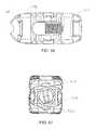
- FIG. 1is a side view of a portion of a human spine illustrating inter-vertebral placement of an expandable interbody/intravertebral body device in accordance with the principles of the present invention.
- FIGS. 2-15show various views of an expandable implant according to one embodiment.
- FIGS. 16-30show various views of an expandable implant according to an alternative embodiment.
- FIGS. 31-38show various views of an expandable implant according to an alternative embodiment.
- FIGS. 39-46show various views of an expandable implant according to an alternative embodiment.
- FIGS. 47-49show various views of an expandable implant according to an alternative embodiment.
- FIGS. 50-53show various views of an expandable implant according to an alternative embodiment.
- FIGS. 54-65show various views of an expandable implant according to an alternative embodiment.
- FIGS. 66-70show various views of an expandable implant according to an alternative embodiment.
- FIGS. 71-75show various views of an expandable implant according to an alternative embodiment.
- FIGS. 76-83show various views of an expandable implant according to an alternative embodiment.
- FIG. 84shows a portion of an expandable implant according to an alternative embodiment.
- the present disclosurerelates to expandable and/or dynamic interbody (between adjacent vertebrae), intravertebral-body (inside the vertebrae) and/or spinal stabilization devices that may or may not be used as interbody fusion cages or devices, interbody/intravertebral bodies/body stabilization devices and/or the like (collectively hereinafter, spinal device(s)) for providing support, stabilization and/or promoting bone growth between or inside vertebrae that have been destabilized or otherwise due to injury, illness and/or the like.
- spinal device(s)for providing support, stabilization and/or promoting bone growth between or inside vertebrae that have been destabilized or otherwise due to injury, illness and/or the like.
- spinal device(s)for providing support, stabilization and/or promoting bone growth between or inside vertebrae that have been destabilized or otherwise due to injury, illness and/or the like.
- the present disclosureprovides various versions of dynamic (expandable and/or expandable and retractable) interbody/intravertebral
- FIG. 1illustrates a representative dynamic spinal body device or expandable implant 10 .
- the implant 10is depicted as implanted or inserted into a human spine 13 of which only a lower portion of the spine 13 is shown.
- the implant 10is illustrated implanted between adjacent upper and lower vertebrae 15 , 17 of the spine 13 in FIG. 1 (hence interbody or intervertebral).
- Vertebrae 15 and 17have portions that face anteriorly (“A”, and from the right as viewed in FIG. 1 ) and portions that face posteriorly (“P”, and from the left as viewed in FIG. 1 ).
- the components of implant 10may be made of any suitable material(s), including a variety of metals, plastics, composites, or other suitable bio-compatible materials.
- one or more components of implant 10may be made of the same material, while in other embodiments, different materials may be used for different components of implant 10 .
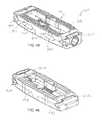
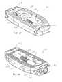
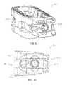
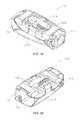
- implant 10is shown according to an exemplary embodiment.
- Implant 10is usable, for example, between and/or within vertebral bodies of the spine, and may share many of the features of the other inter/intra-body implants discussed elsewhere herein. It should be understood that implant 10 may in some embodiments be usable in other portions of the body in addition to the spine, and all such applications are to be understood to be within the scope of the present disclosure.
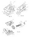
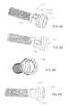
- implant 10includes a first, or front portion 12 (e.g., a first wedge member), a second, or rear portion 14 (e.g., a second wedge member), and a third, intermediate, or control member or portion 16 , which collectively form a body or control assembly that extends along a longitudinal axis 11 of implant 10 .
- a first, or upper support 18e.g., an upper plate, support member, assembly, etc.
- a second, lower support 20e.g., a lower plate, support member, assembly
- first and second supports 18 , 20define a height of implant 10 extending between outer or top surface 48 of first support 18 and outer or lower surface 76 of second support 20 .
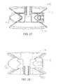
- front portion 12includes a rounded, or bull nose portion intended to facilitate insertion of implant 10 into a patient.
- Front portion 12also includes ramped surfaces 26 , 28 and projections 30 , 32 that facilitate controlled sliding movement between front portion 12 and first and second supports 18 , 20 .
- An aperture 34may be threaded to receive control member 16 to provide an adjustable control mechanism for implant 10 .
- ramped surface 26extends at an angle relative to axis 11
- projection 30extends upward relative to ramped surface 26
- Ramped surface 26is a generally flat surface configured to engage a correspondingly ramped surface (surface 54 ) on first support 18 .
- Projection 30extends laterally across front portion 12 .
- projection 30may have a dovetail shape, while in other embodiments, projection 30 may take other shapes, including having an undercut portion, etc.
- the dovetail shapeprovides a relatively larger top portion and an undercut lower portion such that front portion 12 and first support 18 can slide relative to one another, but the parts cannot be separated, for example, by merely lifting first support 18 away from front portion 12 (e.g., in an upward direction generally perpendicular to axis 11 ).
- Ramped surface 28 and projection 32share similar features to ramped surface 26 and projection 30 , except that ramped surface 28 and projection 32 interface with corresponding surfaces on second support 20 , rather than first support 18 . It should be noted that ramped surfaces 26 , 28 may be inclined relative to axis 11 to provide any desirable adjustment features, as changing the incline of the ramped surfaces will change the rate at which the first and second support members move up/down.
- rear portion 14includes ramped surfaces 36 , 38 , projections 40 , 42 , an aperture, or through-hole 44 , and a counterbore 46 .
- Rear portion 14may define a generally flat rearward-most surface being generally rectangular in shape. In other embodiments, the shape of rear portion 14 may be varied to suit a particular application.
- Ramped surface 36extends at an angle relative to axis 11 , and projection 40 extends upward relative to ramped surface 36 .
- Ramped surface 36is a generally flat surface configured to engage a correspondingly ramped surface (surface 56 ) on first support 18 .
- Projection 40extends laterally across rear portion 14 .
- projection 40may have a dovetail shape (see, e.g., FIG. 15 ), while in other embodiments, projection 40 may take other shapes, including having an undercut portion etc.
- the dovetail shapeprovides a relatively larger top portion and an undercut lower portion such that rear portion 14 and first support 18 can slide relative to one another, but the parts cannot be separated, for example, by merely lifting first support 18 away from rear portion 14 (e.g., in an upward direction generally perpendicular to axis 11 ).
- Ramped surface 38 and projection 42share similar features to ramped surface 36 and projection 40 , except that ramped surface 38 and projection 42 interface with corresponding surfaces on second support 20 , rather than first support 18 . It should be noted that ramped surfaces 36 , 38 may be inclined relative to axis 11 to provide any desirable adjustment features, as changing the incline of the ramped surfaces will change the rate at which the first and second support members move up/down.
- first and second supports 18 , 20are configured to be moveable relative to the body or control assembly (e.g., front and rear portions 12 , 14 and control portion 16 ) such that implant 10 is reconfigurable between a first configuration (e.g., a retracted, collapsed, or minimal configuration), as shown in FIGS. 2-7 , and a second configuration (e.g., an expanded or maximum configuration), as shown in FIGS. 8-13 and any intermediate position therebetween.
- a first configuratione.g., a retracted, collapsed, or minimal configuration
- a second configuratione.g., an expanded or maximum configuration
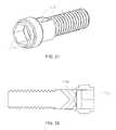
- Control member 16is rotatable and threadingly received by front portion 12 such that rotation of control member 16 in a first (e.g., clockwise) direction causes front and rear portions 12 , 14 to move toward each other, thereby causing first and second supports 18 , 20 to move outward toward the expanded configuration. Conversely, rotation of control member 16 in a second (e.g., counter-clockwise) direction causes front and rear portions 12 , 14 to move away from each other, thereby causing first and second supports 18 , 20 to move inward toward the collapsed configuration. It should be noted that in use, control member 16 may be adjusted so as to maintain first and second supports 18 , 20 in a fully collapsed configuration, a fully expanded configuration, or any desired configuration or intermediate position therebetween.
- First and second supports 18 , 20 and front and rear portions 12 , 14have corresponding geometric features (e.g., correspondingly ramped surfaces) such that displacement of front portion 12 relative to rear portion 14 along axis 11 causes relative planar and/or linear displacement of first and second supports 18 , 20 .
- geometric features of the various componentsmay be varied to provide for varying adjustment features for first and second supports 18 , 20 .
- first and second supports 18 , 20are generally similar in structure.
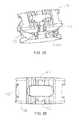
- first support 18includes outer, or top surface 48 , ramped surfaces 54 , 56 , channels 58 , 59 , and two pairs of opposing projections—projections 60 , 62 , and projections 64 , 66 .
- First support 18further includes sidewalls 68 , 70 , pin or retaining member apertures 72 , and inner, or bottom surface 74 .
- Top surface 48includes a number of ridges, or projections 50 , intended to provide a gripping surface for adjacent vertebrae, and a bone graft cavity, or window 52 intended to provide a space to receive bone graft material.
- control member 16extends through through-hole 44 in rear portion 14 and into front portion 12 .
- Head portion 106 of control member 16seats in counterbore 46 of rear portion 14 , and threaded portion 104 threadingly engages aperture 34 of front portion 12 .
- Head portion 106may include an annular recess 108 configured such that a collar 24 can be positioned (e.g., press-fit, welded, etc.) into counterbore 46 rearward of head portion 106 to retain control member 16 in place.
- first and second supports 18 , 20in turn move away from/toward each other.
- opposing projections 60 , 62 on first support 18form a recess, or channel 58 .
- channel 58has a dovetail shape corresponding in shape to projection 30 on front portion 12 .
- projections 64 , 66 in first support 18form channel 59 having a dovetail shape similar in shape to projection 40 on rear portion 14 .
- Projections 30 , 40slide within channels 58 , 59 as first support 18 moves up/down.
- Retaining members or pins 22extend through first and second supports 18 , 20 and act to limit the range of movement of first and second supports 18 , 20 relative to front and rear portions 12 , 14 , and prevent first and second supports 18 , 20 from being completely removed from front and rear portions 12 , 14 .
- Second support 20is similar to first support 18 and includes outer, or bottom surface 76 , ramped surfaces 82 , 84 , channels 86 , 87 , and two pairs of opposing projections—projections 88 , 90 , and projections 92 , 94 . Second support 20 further includes sidewalls 96 , 98 , pin or retaining member apertures 80 , and inner, or top surface 102 . Bottom surface 76 includes a number of ridges, or projections 78 , intended to provide a gripping surface for adjacent vertebrae, and a bone graft cavity, or window 80 intended to provide a space to receive bone graft material.
- the components of second support 20are similar in structure and function to the corresponding components of first support 18 . In other embodiments, the components of second support 20 may provide additional and/or different structural and/or functional features relative to the corresponding components of first support 18 .
- implant 10may share various features with the other implants described herein, and be made of the same, similar, or different materials.
- various components of implant 10may be made of metal, plastic, composites, or other suitable bio-compatible materials.
- implant 10may be usable in connection with the spine or other parts of the body.
- Implant 110is shown according to an exemplary embodiment.
- Implant 110is usable, for example, between and/or within vertebral bodies of the spine, and may share many of the features of the other inter/intra-body implants discussed elsewhere herein. It should be understood that implant 110 may in some embodiments be usable in other portions of the body in addition to the spine, and all such applications are to be understood to be within the scope of the present disclosure. Implant 110 is generally similar to implant 10 in structure and function except with respect to the additional alignment features discussed below.
- implant 110includes a first, or front portion 112 , a second, or rear portion 114 , and a third, intermediate, or control member or portion 116 , which collectively form a body or control assembly that extends along a longitudinal axis 111 of implant 110 .
- a first, or upper support 118e.g., an upper plate or support member, etc.
- a second, lower support 120e.g., a lower plate or support member
- first and second supports 118 , 120define a height of implant 110 extending between outer or top surface 148 of first support 118 and outer or lower surface 176 of second support 120 .
- front portion 112includes a rounded, or bull nose portion intended to facilitate insertion of implant 110 into a patient.
- Front portion 112also includes ramped surfaces and projections (e.g., similar to ramped surfaces 26 , 28 and projections 30 , 32 ) that facilitate controlled sliding movement between front portion 112 and first and second supports 118 , 120 .
- An aperturemay be threaded to receive control member 116 to provide an adjustable control mechanism for implant 110 .
- the ramped surfacesextend at an angle relative to axis 111 , and the projections extend upward/downward relative to the ramped surfaces.
- the ramped surfacesare generally flat surfaces configured to engage a correspondingly ramped surface on first support 118 .
- the projectionsextend laterally across front portion 112 .
- the projectionsmay have a dovetail shape, while in other embodiments, the projections may take other shapes, including having an undercut portion, etc.
- implant 110includes front and rear, upper and lower ramped surfaces and projections configured to provide the interface between front and rear portions 112 , 114 and first and second supports 118 , 120 .
- first and second supports 118 , 120 and front and rear portions 112 , 114have corresponding geometric features (e.g., correspondingly ramped surfaces) such that displacement of front portion 112 relative to rear portion 114 along axis 111 causes relative planar and/or linear displacement of first and second supports 118 , 120 .
- geometric features of the various componentsmay be varied to provide for varying adjustment features for first and second supports 118 , 120 .
- control member 116includes a head portion and a body portion and extends through a through-hole in rear portion 114 and into front portion 112 .
- the head portion of control member 116seats in a counterbore of rear portion 114 , and the threaded portion of the body threadingly engages an aperture of front portion 112 .
- the head portionmay include an annular recess (similar to head portion 106 of implant 10 ) configured such that a collar 124 can be positioned (e.g., press-fit, welded, etc.) into the counterbore rearward of the head portion to retain control member 116 in place.
- control member 116As a user rotates control member 116 , front portion 112 and rear portion 114 move toward/away from each other (depending on the direction of rotation), and first and second supports 118 , 120 in turn move away from/toward each other. While the Figures generally show control member 116 threadingly engaging front portion 112 , in other embodiments, other adjustment mechanisms may be used (e.g., ratchet mechanisms, indents/detents, etc.).
- Opposing projections 160 , 162 on first support 118form a recess, or channel 158 .
- channel 158has a dovetail shape corresponding in shape to projection 130 on front portion 112 .
- projections 164 , 166 in first support 118form channel 159 having a dovetail shape similar in shape to projection 140 on rear portion 114 . Projections 130 , 140 slide within channels 158 , 159 as first support 118 moves up/down.
- retaining members or pinsextend through first and second supports 118 , 120 and act to limit the range of movement of first and second supports 118 , 120 relative to front and rear portions 112 , 114 , and prevent first and second supports 118 , 120 from being completely removed from front and rear portions 112 , 114 .
- Second support 120includes similar features such as an outer, or bottom surface, ramped surfaces, channels, and two pairs of opposing projections.
- implant 110further includes an alignment feature intended to maintain alignment between first and second supports 118 , 120 during use.
- second support 120includes one or more alignment members 150 , 152 (e.g., extensions, projections, etc.) that extend generally upward as shown in FIG. 19 (e.g., in a direction generally perpendicular to axis 111 ).
- Members 150 , 152are received in recesses 154 , 156 (e.g., channels, grooves, slots, etc.), respectively, formed in first support 118 .
- Members 150 , 152 and recesses 154 , 156have corresponding geometric features to ensure a snug fit between components. For example, as shown in FIG.
- members 150 , 152are generally U-shaped in cross-section, and recesses 154 , 156 are shaped to receive the U-shaped members.
- the alignment featuresprevent relative “rocking” of the supports, and in some embodiments serve to maintain a generally parallel relationship between the supports. In some embodiments, spaces or gaps may be provided between members 150 , 152 and recesses 154 , 156 to enable a predetermined amount of angular offset between the supports.
- members 150 , 152are formed so as to be generally flush with the exterior surface of first support 118 (e.g., along a side or top surface). In other embodiments, members 150 may be recessed from, or alternatively protrude beyond, the exterior surface of first support 118 . Further, while FIGS. 16-30 show two alignment members 150 , 152 , in various alternative embodiments fewer or more alignment members and/or recesses may be utilized (e.g., 1, 3, 4, etc.). Further yet, members 150 , 152 may be integrally formed with, or removably coupled to, a remainder portion of second support 120 .
- the relative positions of alignment members 150 , 152 and recesses 154 , 156are reversed (e.g., such that members 150 , 152 are provided on first support 118 and recesses 154 , 156 are provided on second support 120 ).
- Other variations in the size, number, and placement of members 150 , 152 and recesses 154 , 156may be made according to various embodiments.
- implant 110may share various features with the other implants described herein, and be made of the same, similar, or different materials.
- various components of implant 110may be made of metal, plastic, composites, or other suitable bio-compatible materials.
- implant 110may be usable in connection with the spine or other parts of the body.
- pins similar to pins 22may be used in conjunction with implant 110 or any of the other implants shown and described herein.
- the implants shown in FIGS. 1-15 and 16-30share various common features.
- the control member or screwe.g., 16 , 116
- the control member 16may be received by or through rear portion 14 in a counterbore and held captive by collar or ring 24 , such that control member 16 is free to rotate within rear portion 14 , but does not threadingly engage rear portion 14 .
- rear portion 14remains fixed relative to control member 16 as control member 16 is rotated.
- Control member 16threadingly engages a threaded aperture 34 defined by a boss extending rearward from front portion 12 , such that as control member 16 rotates, front portion 12 moves relative to control member 16 (e.g., control member 16 moves into or out of the threaded boss of front portion 12 ).
- control member 16is contained entirely within the periphery of front and rear portions 12 , 14 .
- the control member 16may in some embodiments be configured to be flush with the outer sides of front and rear portions 12 , 14 .
- the control member 16is recessed within front and/or rear portions 12 , 14 .
- front portion 12has a solid, bull-nose configuration such that control member 16 is concealed therein.
- the implantsinclude grooves that may help secure the implant in the body of a patient, by providing spaces for structures in the body of a patient to engage the grooves.
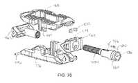
- Implant 210is shown according to an exemplary embodiment.
- Implant 210is usable, for example, between and/or within vertebral bodies of the spine, and may share many of the features of the other inter/intra-body implants discussed elsewhere herein. It should be understood that implant 210 may in some embodiments be usable in other portions of the body in addition to the spine, and all such applications are to be understood to be within the scope of the present disclosure.
- Implant 210is generally similar to implants 10 and 110 in structure and function except with respect to the additional access port features discussed below. As such, implant 210 is understood to include any or all of the features of implants 10 and 110 to the extent consistent with the additional features of implant 210 described herein (e.g., retention pins, dovetail projections and ramped surfaces, alignment features, etc.).
- implant 210includes a first, or front portion 212 , a second, or rear portion 214 , and a third, intermediate, or control member or portion 216 , which collectively form a body or control assembly that extends along a longitudinal axis of implant 210 .
- a first, or upper support 218e.g., an upper plate or support member, etc.
- a second, lower support 220e.g., a lower plate or support member
- first and second supports 218 , 220define a height of implant 210 extending between the outer or top surface of first support 218 and the outer or lower surface of second support 220 .
- control member 216includes a head portion 230 , a collar recess 232 , a threaded portion 234 , a tool recess 236 , and access ports 238 .
- Threaded portion 234 and the non-threaded portion of control member 216 including access ports 238collectively form a body portion for control member 216 .
- Head portion 230is received within a counterbore in rear portion 214 .
- Collar recess 232is configured to enable placement of collar 224 into a position to retain head portion 230 within the counterbore in rear portion 214 .
- Threaded portion 234is configured to threadingly engage a threaded aperture provided by front portion 212 .
- Tool recess 236is formed in the rearward portion of head portion 230 and communicates with access ports 238 , which extend to opposite sides of control member 216 .
- Tool recess 236is configured to receive a tool to enable threading manipulation of control member 216 .
- Tool recess 236 and access ports 238are collectively configured to provide a fluid path to an interior of implant 210 and enable delivery of fluid, bone growth material, or other material to an interior of implant 210 .
- two access ports 238are in communication with tool recess 236 and extend to opposite sides of control member 216 .
- more or fewer access ports 238may be utilized, and the size and shape of the individual access ports 238 may be varied to suit a particular application, size of implant, and the like.
- Access ports 238are positioned to provide fluid communication with an interior area of implant 210 .
- Implant 260is shown according to an exemplary embodiment.
- Implant 260is usable, for example, between and/or within vertebral bodies of the spine, and may share many of the features of the other inter/intra-body implants discussed elsewhere herein. It should be understood that implant 260 may in some embodiments be usable in other portions of the body in addition to the spine, and all such applications are to be understood to be within the scope of the present disclosure.
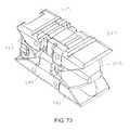
- Implant 260is generally similar to implants 10 , 110 , and 210 (and the other implants described herein) in structure and function except with respect to the additional conical projection, side bone graft window, and elongated component features discussed below.
- implant 260is understood to include any or all of the features of the other implants described herein to the extent consistent with the additional features of implant 260 described herein (e.g., retention pins, dovetail projections and ramped surfaces, alignment features, control member access port(s), etc.).
- implant 260includes a first, or front portion 262 , a second, or rear portion 264 , and a third, intermediate, or control member or portion 266 , which collectively form a body or control assembly that extends along a longitudinal axis of implant 260 .
- a first, or upper support 268e.g., an upper plate or support member, etc.
- a second, lower support 270e.g., a lower plate or support member
- first and second supports 268 , 270define a height of implant 260 extending between the outer or top surface of first support 268 and the outer or lower surface of second support 270 .
- control member 266includes a head portion 280 , a collar recess 282 , a threaded portion 284 , a tool recess 286 , and access ports 288 .
- Head portion 280is received within a counterbore in rear portion 264 .
- Collar recess 282is configured to enable placement of collar 274 into a position to retain head portion 280 within the counterbore of rear portion 264 .
- Threaded portion 284is configured to threadingly engage a threaded aperture provided by front portion 262 .
- Tool recess 286is formed in the rearward portion of head portion 280 and communicates with access ports 288 , which extend to opposite sides of control member 266 .
- Tool recess 286is configured to receive a tool to enable threading manipulation of control member 266 .
- Tool recess 286 and access ports 288are collectively configured to provide a fluid path to an interior of implant 260 and enable delivery of fluid, bone growth material, or other material to an interior of implant 260 .
- implant 260defines a first side 290 and a second, opposite side 292 .
- First and second sides 290 , 292are generally formed by the sidewalls of top and bottom supports 268 , 270 .
- one or both of first and second sides 290 , 292include side bone graft apertures or windows.
- first side 290includes side apertures 294 and second side 292 forms a generally solid sidewall.
- FIG. 45illustrates first side 290 as including two bone graft apertures 294 , according to various alternative embodiments, one or both of first side 290 and second side 292 may include more or fewer side apertures.
- top and bottom supports 268 , 270may include a projection 296 (e.g., a conical projection) at one or both ends. Projections 296 may extend above the other portions of top and bottom supports 268 , 270 (e.g., teeth, etc.)
- top and bottom supports 268 , 270have a generally symmetric profile about control member 266 , as shown for example, in FIG. 42 .
- Implant 260may further be elongated relative to other implants illustrated herein, having an overall length to overall width ratio (in the collapsed configuration) of 2, 3, 4, or more (or another ratio, such as a range of between 2 and 5, between 2 and 4, etc.).
- Implant 310is shown according to an exemplary embodiment.
- Implant 310is usable, for example, between and/or within vertebral bodies of the spine, and may share many of the features of the other inter/intra-body implants discussed elsewhere herein. It should be understood that implant 310 may in some embodiments be usable in other portions of the body in addition to the spine, and all such applications are to be understood to be within the scope of the present disclosure.
- Implant 310is generally similar to implants 260 (and the other implants described herein) in structure and function except with respect to the additional asymmetric component features discussed below.
- implant 310is understood to include any or all of the features of the other implants described herein to the extent consistent with the additional features of implant 310 described herein (e.g., retention pins, dovetail projections and ramped surfaces, alignment features, control member access port(s), etc.).
- implant 310includes a first, or front portion 312 , a second, or rear portion 314 , and a third, intermediate, or control member or portion 316 , which collectively form a body or control assembly that extends along a longitudinal axis of implant 310 .
- a first, or upper support 318e.g., an upper plate or support member, etc.
- a second, lower support 320e.g., a lower plate or support member
- first and second supports 318 , 320define a height of implant 310 extending between the outer or top surface of first support 318 and the outer or lower surface of second support 320 .
- implant 310defines a first side portion 330 and a second side portion 332 .
- first and second side portions 330 , 332include side bone graft apertures or windows.
- first side 330includes side apertures 334 .
- FIG. 48illustrates first side 330 as including two bone graft apertures 334 , according to various alternative embodiments, one or both of first side 330 and second side 332 may include more or fewer side apertures.
- first side portion 330 and second side portionprovide an asymmetric profile about control member 316 , as shown for example in FIG. 49 .
- a portion of first side portion 330extends away from control member 316 a further distance than the corresponding portions of second side portion 332 , forming an asymmetric shape (e.g., a “D” or similar shape).
- Providing an asymmetric profilemay provide benefits in particular applications where additional support is desired and/or when placement of implant 310 is difficult. While FIGS. 47-49 shown implant 310 having a general “D” asymmetric shape, according to various alternative embodiments, other asymmetric shapes and configurations may be utilized.
- Implant 360is shown according to an exemplary embodiment.
- Implant 360is usable, for example, between and/or within vertebral bodies of the spine, and may share many of the features of the other inter/intra-body implants discussed elsewhere herein. It should be understood that implant 360 may in some embodiments be usable in other portions of the body in addition to the spine, and all such applications are to be understood to be within the scope of the present disclosure.
- Implant 360is generally similar to implants 260 and 310 (and the other implants described herein) in structure and function except with respect to the additional lateral taper features discussed below.
- implant 360is understood to include any or all of the features of the other implants described herein to the extent consistent with the additional features of implant 360 described herein (e.g., retention pins, dovetail projections and ramped surfaces, alignment features, control member access port(s), etc.).
- implant 360includes a first, or front portion 362 , a second, or rear portion 364 , and a third, intermediate, or control member or portion 366 , which collectively form a body or control assembly that extends along a longitudinal axis of implant 360 .
- a first, or upper support 368e.g., an upper plate or support member, etc.
- a second, lower support 370e.g., a lower plate or support member
- first and second supports 368 , 370define a height of implant 360 extending between the outer or top surface of first support 368 and the outer or lower surface of second support 370 .
- the height of implant 360decreases in a lateral direction.
- implant 360defines a first side portion 380 and a second side portion 382 .
- first and second side portions 380 , 382include side bone graft apertures or windows.
- second side 382includes side apertures 384 . While FIG. 50 illustrates second side 382 as including two bone graft apertures 384 , according to various alternative embodiments, one or both of first side 380 and second side 382 may include more or fewer side apertures.
- implant 360is configured to provide a predetermined lateral taper that remains constant as implant 360 is moved between a collapsed configuration (see FIGS. 50-51 ) and an expanded configuration (see FIGS. 52-53 ).
- a first lateral sidesuch as side 380 may have a first height that is larger than a height of second lateral side 382 .
- the degree of taper between the first and second lateral sides 380 , 382may be adjusted to suit a particular embodiment (e.g., a desired spinal curvature).
- both the top and bottom supports 368 , 370may include outer surfaces (e.g. top and bottom surfaces) that define a lateral angular offset from a parallel configuration (e.g., a configuration where the top and bottom supports 368 , 370 are generally parallel).
- top and bottom supports 368 and 370move toward and away from each other in a linear manner, such that the degree of taper remains constant.
- other configurationsmay be utilized to provide non-linear movement and a varying lateral taper.
- FIGS. 50-53illustrate an implant having a constant lateral taper, according to various alternative embodiments, implants may be provided having a variable longitudinal taper.
- Implant 410is shown according to an exemplary embodiment.
- Implant 410is usable, for example, between and/or within vertebral bodies of the spine, and may share many of the features of the other inter/intra-body implants discussed elsewhere herein. It should be understood that implant 410 may in some embodiments be usable in other portions of the body in addition to the spine, and all such applications are to be understood to be within the scope of the present disclosure.
- Implant 410is generally similar to implants 260 and 310 (and the other implants described herein) in structure and function except with respect to the additional longitudinal taper features discussed below.
- implant 410is understood to include any or all of the features of the other implants described herein to the extent consistent with the additional features of implant 410 described herein (e.g., retention pins, dovetail projections and ramped surfaces, alignment features, control member access port(s), etc.).
- implant 410includes a first, or front portion 412 , a second, or rear portion 414 , and a third, intermediate, or control member or portion 416 , which collectively form a body or control assembly that extends along a longitudinal axis of implant 410 .
- front portion 412includes a through hole 431 configured to enable control member 416 to extend through front portion 412 .
- a first, or upper support 418e.g., an upper plate or support member, etc.
- a second, lower support 420e.g., a lower plate or support member
- first and second supports 418 , 420define a height of implant 410 extending between the outer or top surface of first support 418 and the outer or lower surface of second support 420 .
- the height of implant 410decreases in a longitudinal direction (e.g., to provide a longitudinal taper feature).
- implant 410is configured to provide a predetermined longitudinal taper that remains constant as implant 410 is moved between a collapsed configuration (see FIGS. 54-55 ) and an expanded configuration (see FIGS. 57-58 ).
- both the top and bottom supports 418 , 420may include outer surfaces (e.g. top and bottom surfaces) that define a lateral angular offset from a parallel configuration (e.g., a configuration where the top and bottom supports 418 , 420 are generally parallel).
- implant 410defines a longitudinal axis extending along control member 416 .
- Top support 418defines a first end 426 , a second end 428 , and a top surface 421 extending between first and second ends 426 , 428 .
- First and second ends 426 , 428define an overall taper to top surface 421 .
- top surface 421may define an arcuate shape between first end 426 and second end 428 (e.g., such that top surface 421 has a slight curvature between first and second ends 426 , 428 ).
- top surface 421may define a substantially planar surface between first and second ends 426 , 428 .
- Bottom support 420defines a first end 425 , a second end 427 , and a bottom surface 423 extending between first and second ends 425 , 427 .
- First and second ends 425 , 427define an overall taper to top surface 423 .
- top surface 423may define an arcuate shape between first end 425 and second end 427 (e.g., such that top surface 423 has a slight curvature between first and second ends 425 , 427 ).
- top surface 423may define a substantially planar surface between first and second ends 425 , 427 .
- top and bottom supports 418 and 420move toward and away from each other in a linear manner, such that the degree of taper remains constant.
- other configurationsmay be utilized to provide non-linear movement and a varying longitudinal taper.
- FIGS. 54-58illustrate an implant having a constant longitudinal taper, according to various alternative embodiments, implants may be provided having a variable longitudinal taper.
- implant 410includes one or more retaining members to retain control member 416 in a desired longitudinal position.
- implant 410includes retaining members 422 received in side apertures 424 on opposing sides of rear support 414 .
- Control member 416includes a head portion 430 , a groove 432 , and a threaded portion 434 .
- Control member 416further includes a tool recess 436 in fluid communication with access ports 438 .
- Retaining members 422are configured to extend through rear support 414 and be received within groove 432 of control member 416 , such that control member 416 is longitudinally fixed relative to rear support 414 , but also rotatable relative to rear support 414 .
- FIG. 61illustrates retaining members 422 extending into rear support 414 from opposing lateral sides. In various alternative embodiments, retaining members may be used that extend through other portions, such as opposing top and bottom sides.
- Implant 460is shown according to an exemplary embodiment.
- Implant 460is usable, for example, between and/or within vertebral bodies of the spine, and may share many of the features of the other inter/intra-body implants discussed elsewhere herein. It should be understood that implant 460 may in some embodiments be usable in other portions of the body in addition to the spine, and all such applications are to be understood to be within the scope of the present disclosure.
- Implant 460is generally similar to the other implants described herein in structure and function except with respect to the additional retaining member features discussed below.
- implant 460is understood to include any or all of the features of the other implants described herein to the extent consistent with the additional features of implant 460 described herein (e.g., retention pins, dovetail projections and ramped surfaces, alignment features, control member access port(s), etc.).
- implant 460includes a first, or front portion 462 , a second, or rear portion 464 , and a third, intermediate, or control member or portion 466 , which collectively form a body or control assembly that extends along a longitudinal axis of implant 460 .
- a first, or upper support 468e.g., an upper plate or support member, etc.
- a second, lower support 470e.g., a lower plate or support member
- first and second supports 468 , 470define a height of implant 460 extending between the outer or top surface of first support 468 and the outer or lower surface of second support 470 .
- top and bottom supports 468 , 470may include tapered corner sections 490 , 492 to facilitate insertion/removal of implant 460 , etc.
- top and bottom supports 468 , 470are retained by upper and lower pins 494 , 496 .
- upper pins 494extend through opposite sides of one end of top support 468
- lower pins 496extend through opposite sides of an opposite end of bottom support 470 .
- Pins 494 , 496act to limit expansion of implant 460 and prevent removal of top and bottom supports 468 , 470 from front and rear portions 462 , 464 .
- two retaining pinsextend into each side of implant 460 . In other embodiments, other numbers of retaining pins may be used, as shown for example in various other embodiments herein.
- implant 460includes one or more retaining members to retain control member 466 in a desired longitudinal position.
- implant 460includes retaining members 472 received in top and bottom apertures 474 on opposing top and bottom sides of rear support 464 .
- Control member 466includes a head portion 480 , a groove 482 , and a threaded portion 484 .
- Control member 466further includes a tool recess 486 in fluid communication with access ports 488 .
- Retaining members 472are configured to extend through rear support 464 and be received within groove 482 of control member 466 , such that control member 466 is longitudinally fixed relative to rear support 464 , but also rotatable relative to rear support 464 .
- FIG. 70illustrates retaining members 472 extending into rear support 464 from opposing top and bottom sides. In various alternative embodiments, retaining members may be used that extend through other portions, such as opposing lateral sides. (e.g., as discussed with respect to implant 410 )
- Implant 510is shown according to an exemplary embodiment.
- Implant 510is usable, for example, between and/or within vertebral bodies of the spine, and may share many of the features of the other inter/intra-body implants discussed elsewhere herein. It should be understood that implant 510 may in some embodiments be usable in other portions of the body in addition to the spine, and all such applications are to be understood to be within the scope of the present disclosure.
- Implant 510is generally similar to the other implants discussed herein in structure and function except with respect to the two-piece top and bottom support member features discussed below. As such, implant 510 is understood to include any or all of the features of the other implants described herein to the extent consistent with the additional features of implant 510 described herein.
- implant 510includes a first, or front portion 512 , a second, or rear portion 514 , and a third, intermediate, or control member or portion 516 , which collectively form a body or control assembly that extends along a longitudinal axis of implant 510 .
- a first, or upper support assembly 518e.g., an upper plate or support member, etc.
- a second, lower support assembly 520e.g., a lower plate or support member
- first and second support assemblies 518 , 520define a height of implant 520 extending between the outer or top surface of first support assembly 518 and the outer or lower surface of second support assembly 520 .
- Front portion 512includes ramped surfaces 562 and a threaded bore 564 .
- Rear portion 514includes dovetailed projections 566 and recess or aperture 568 . Ramped surfaces 562 and dovetailed projections 566 facilitate controlled expansion and contraction of top support assembly 518 and bottom support assembly 520 relative to one another.
- top support assembly 518includes a first portion 522 and a second portion 524 pivotally coupled to first portion 522 by way of a top pivot pin 530 .
- First portion 522defines an extension portion 532 that at least partially extends into a recess 534 in second portion 524 .
- Top guide pins 526extend through second portion 524 and into upper slots 528 in first portion 522 to limit the range of pivotal motion of first portion 522 relative to second portion 524 about top pivot pin 530 .
- First portion 522includes a ramped surface 536
- second portion 524includes a dovetailed recess 538 .
- Ramped surface 536slidingly interfaces with a corresponding ramped surface 562 on front portion 512
- dovetailed recess 538slidingly interfaces with a dovetailed projection 566 on rear portion 514 .
- bottom support assembly 520includes a first portion 542 and a second portion 544 pivotally coupled to first portion 542 by way of a bottom pivot pin 550 .
- First portion 542defines an extension portion 552 that at least partially extends into a recess 554 in second portion 524 .
- Bottom guide pins 546extend through second portion 544 and into bottom slots 548 in first portion 542 to limit the range of pivotal motion of first portion 542 relative to second portion 544 about bottom pivot pin 550 .
- First portion 542includes a ramped surface 556
- second portion 524includes a dovetailed recess 558 .
- Ramped surface 556slidingly interfaces with a corresponding ramped surface 562 on front portion 512
- dovetailed recess 558slidingly interfaces with a dovetailed projection 566 on rear portion 514 .
- implant 510includes alignment features configured to maintain proper alignment between at least a portion of top support assembly 518 and at least a portion of bottom support assembly 520 .
- an upper alignment guide 540 on second portion 524 of top support assembly 518slidingly engages a correspondingly shaped lower alignment guide 560 on second portion 544 of bottom support assembly 520 .
- second portions 524 , 544remain aligned (e.g., move in a linear fashion relative to one another.
- implant 510is moveable from a first, fully collapsed and aligned position, as shown in FIG. 71 , to a second, collapsed and angulated position, as shown in FIG. 72 , to a third, expanded and angulated position, as shown in FIG. 73 .
- Implant 510may be positioned at any desired intermediate position between the first, second, and third positions.
- a first amount of rotation of control member 516causes angulation of first portions 522 , 542 relative to second portions 524 , 544 .
- first portion 522rotates about top pivot pin 530 and first portion 542 rotates about bottom pivot pin 550 .
- First portions 522 , 542continue to angulate until top and bottom guide pins 526 , 546 are retained by upper and lower slots 528 , 548 , which define the maximum amount of angulation for first portions 522 , 542 .
- control member 516causes expansion of second members 524 , 544 (and therefore also first members 522 , 542 ) relative to one another in a generally linear fashion (e.g., through the interaction of alignment guides 540 , 560 ).
- front portion 512 and first portions 522 , 542have generally flat, correspondingly shaped ramped surfaces 562 (on front portion 512 ), 536 (on first portion 522 of top support assembly 518 ), and 556 (on first portion 542 of bottom support assembly 520 ).
- rear portion 514includes dovetailed projections 566 , which are received within dovetailed recesses 438 (on second portion 524 of top support assembly 518 ) and 558 (on second portion 544 of bottom support assembly 520 ).
- the angulation and expansion featuresenable a user to initially install implant 510 in a collapsed, aligned position, as shown in FIG. 71 , which may facilitate initial insertion and adjustment of the device.
- implant 510may be moved to a desired angulated and/or expanded configuration, as shown in FIGS. 72 and 73 .
- the outer surfaces (e.g., top and bottom surfaces) of first portions 522 , 542are offset (e.g. angularly offset) from the outer surfaces of second portions 524 , 544 , and angularly offset from the longitudinal axis of implant 510 (e.g., an axis extending along control member 516 ).
- the amount of angulationmay be varied to suit a particular application (e.g., an amount of spinal curvature to be accommodated by the implant, etc.).
- Implant 610is shown according to an exemplary embodiment.
- Implant 610is usable, for example, between and/or within vertebral bodies of the spine, and may share many of the features of the other inter/intra-body implants discussed elsewhere herein. It should be understood that implant 610 may in some embodiments be usable in other portions of the body in addition to the spine, and all such applications are to be understood to be within the scope of the present disclosure.
- Implant 610is generally similar to the other implants discussed herein in structure and function except with respect to the two-piece top and bottom support member and specific control member features discussed below. As such, implant 610 is understood to include any or all of the features of the other implants described herein to the extent consistent with the additional features of implant 610 described herein.
- implant 610includes a first, or front portion 612 , a second, or rear portion 614 , a first, or inner, control member 615 , a second, or outer, control member 616 , and a receiver member 617 , which collectively form a body or control assembly that extends along a longitudinal axis of implant 610 .
- a first, or upper support assembly 618e.g., an upper plate or support member, etc.
- a second, lower support assembly 620e.g., a lower plate or support member
- first and second support assemblies 618 , 620define a height of implant 610 extending between the outer or top surface of first support assembly 618 and the outer or lower surface of second support assembly 620 .
- Front portion 612includes ramped surfaces 654 and a receiver recess or bore 656 .
- Rear portion 614includes ramped surfaces 658 and control recess or bore 660 .
- Ramped surfaces 654 , 658facilitate controlled expansion and contraction of top support assembly 618 and bottom support assembly 620 relative to one another.
- top support assembly 618includes a first or inner portion 622 and a second or outer portion 624 pivotally coupled to first portion 622 by way of a top pivot pin 626 .
- First portion 622at least partially extends into a recess 628 in second portion 624 .
- First portion 622includes a ramped surface 630
- second portion 624includes a ramped surface 632 .
- Ramped surface 630slidingly interfaces with a corresponding ramped surface 654 on front portion 612
- ramped surface 632slidingly interfaces with a corresponding ramped surface 658 on rear portion 614 .
- bottom support assembly 620includes a first or inner portion 638 and a second or outer portion 640 pivotally coupled to first portion 638 by way of a bottom pivot pin 642 .
- First portion 638at least partially extends into a recess 644 in second portion 640 .
- First portion 638includes a ramped surface 646
- second portion 640includes a ramped surface 648 .
- Ramped surface 646slidingly interfaces with a corresponding ramped surface 654 on front portion 612
- ramped surface 648slidingly interfaces with ramped surface 658 on rear portion 614 .
- implant 610includes alignment features configured to limit a degree of angulation of second portions 624 , 640 relative to first portions 622 , 638 .
- first portion 622 of top support assembly 618includes a single alignment guide or member 634 that is received between two alignment guides or members 650 on first portion 638 of bottom support assembly 620 .
- Alignment guides 634 , 650are collectively received in a top alignment recess in second portion 624 of top support assembly 618 and a bottom alignment recess 644 in second portion 640 of bottom support assembly 620 .
- the various alignment componentsmay be configured to enable a predetermined amount of angulation between first portions 622 , 63 and second portions 624 , 640 .
- implant 610is moveable from a first, fully collapsed and aligned position, as shown in FIGS. 76 and 79 , to a second, expanded and aligned position, as shown in FIGS. 77 and 80 , to a third, expanded and angulated position, as shown in FIGS. 78 and 81 .
- Implant 610may be positioned at any desired intermediate position between the first, second, and third positions. Furthermore, the order of expansion and angulation may be reversed, or alternated, during installation.
- FIGS. 77 and 80show implant 610 with outer control member 616 having been threaded into receiver 617 by way of threading engagement of the outer threads 668 of outer control member 616 and the inner threads 676 of receiver 617 .
- front portion 612 and rear portion 614move toward/away from each other, top and bottom support assemblies 618 , 620 likewise move away from/toward each other.
- Threading of inner control member 615 within outer control 616 membercauses second portions 624 , 640 to angulate relative to first portions 622 , 638 .
- FIGS. 78 and 81show implant 610 with inner control member 615 having been threaded into outer control member 616 , causing second portions 624 , 640 to rotate about top and bottom pivot pins 626 , 642 , causing second portions 624 , 640 to become angularly offset relative to first portions 622 , 638 .
- the angulation and expansion featuresenable a user to initially install implant 610 in a collapsed, aligned position, as shown in FIGS. 76 and 69 , which may facilitate initial insertion and adjustment of the device. Once in proper position, implant 610 may be moved to a desired angulated and/or expanded configuration, as shown in FIGS. 77-78 and 80-81 . In the fully expanded and angulated position, as shown in FIGS. 78 and 81 , the outer surfaces (e.g., top and bottom surfaces) of second portions 624 , 640 are offset (e.g.
- angularly offsetfrom the outer surfaces of first portions 622 , 638 , and angularly offset from the longitudinal axis of implant 610 (e.g., an axis extending along outer control member 616 ).
- the amount of angulationmay be varied to suit a particular application (e.g., an amount of spinal curvature to be accommodated by the implant, etc.).
- the portionincludes a member 650 , which may be similar to various components described with respect to the various other embodiments disclosed herein.
- member 650may form part of a control assembly and act as a rear member similar to rear portions 14 , 114 , 214 , etc.
- access to the interior of the various implants disclosed hereinmay be by way of member 650 .
- Member 650includes a control member 652 and an access aperture 654 .
- Control member 652acts to control expansion and contraction of the implant, and aperture 654 enables access to the interior of the implant.
- the access features of member 650may be implemented in any of the implant components described herein, including the various front and rear portions, top and bottom supports, etc. All such combinations of features are to be understood to be within the scope of the present disclosure.
Landscapes
- Health & Medical Sciences (AREA)
- Engineering & Computer Science (AREA)
- Biomedical Technology (AREA)
- Orthopedic Medicine & Surgery (AREA)
- Neurology (AREA)
- Life Sciences & Earth Sciences (AREA)
- Animal Behavior & Ethology (AREA)
- Veterinary Medicine (AREA)
- Public Health (AREA)
- Heart & Thoracic Surgery (AREA)
- General Health & Medical Sciences (AREA)
- Cardiology (AREA)
- Vascular Medicine (AREA)
- Transplantation (AREA)
- Oral & Maxillofacial Surgery (AREA)
- Surgery (AREA)
- Nuclear Medicine, Radiotherapy & Molecular Imaging (AREA)
- Medical Informatics (AREA)
- Molecular Biology (AREA)
- Prostheses (AREA)
Abstract
Description
Claims (11)
Priority Applications (7)
| Application Number | Priority Date | Filing Date | Title |
|---|---|---|---|
| US15/497,011US10383741B2 (en) | 2013-03-13 | 2017-04-25 | Expandable spinal interbody assembly |
| US15/497,044US10426632B2 (en) | 2013-03-13 | 2017-04-25 | Expandable spinal interbody assembly |
| PCT/US2018/029120WO2018200507A1 (en) | 2017-04-25 | 2018-04-24 | Expandable spinal interbody assembly |
| EP18723322.6AEP3614974B1 (en) | 2017-04-25 | 2018-04-24 | Expandable spinal interbody assembly |
| US16/009,616US11304818B2 (en) | 2013-03-13 | 2018-06-15 | Expandable spinal interbody assembly |
| US16/548,134US11103362B2 (en) | 2013-03-13 | 2019-08-22 | Expandable implant assembly |
| US17/385,558US11986398B2 (en) | 2013-03-13 | 2021-07-26 | Expandable implant assembly |
Applications Claiming Priority (3)
| Application Number | Priority Date | Filing Date | Title |
|---|---|---|---|
| US13/802,110US9034041B2 (en) | 2005-03-31 | 2013-03-13 | Expandable spinal interbody and intravertebral body devices |
| US14/714,821US9801733B2 (en) | 2005-03-31 | 2015-05-18 | Expandable spinal interbody and intravertebral body devices |
| US15/497,011US10383741B2 (en) | 2013-03-13 | 2017-04-25 | Expandable spinal interbody assembly |
Related Parent Applications (1)
| Application Number | Title | Priority Date | Filing Date |
|---|---|---|---|
| US14/714,821Continuation-In-PartUS9801733B2 (en) | 2005-03-31 | 2015-05-18 | Expandable spinal interbody and intravertebral body devices |
Related Child Applications (1)
| Application Number | Title | Priority Date | Filing Date |
|---|---|---|---|
| US16/009,616Continuation-In-PartUS11304818B2 (en) | 2013-03-13 | 2018-06-15 | Expandable spinal interbody assembly |
Publications (2)
| Publication Number | Publication Date |
|---|---|
| US20170224505A1 US20170224505A1 (en) | 2017-08-10 |
| US10383741B2true US10383741B2 (en) | 2019-08-20 |
Family
ID=59496024
Family Applications (1)
| Application Number | Title | Priority Date | Filing Date |
|---|---|---|---|
| US15/497,011Active2033-06-23US10383741B2 (en) | 2013-03-13 | 2017-04-25 | Expandable spinal interbody assembly |
Country Status (1)
| Country | Link |
|---|---|
| US (1) | US10383741B2 (en) |
Cited By (18)
| Publication number | Priority date | Publication date | Assignee | Title |
|---|---|---|---|---|
| US11033403B2 (en) | 2017-07-10 | 2021-06-15 | Life Spine, Inc. | Expandable implant assembly |
| US11103362B2 (en) | 2013-03-13 | 2021-08-31 | Life Spine, Inc. | Expandable implant assembly |
| US20210275319A1 (en)* | 2020-03-05 | 2021-09-09 | Alphatec Spine, Inc. | Expandable Interbodies and Related Methods |
| US11173044B1 (en) | 2021-04-20 | 2021-11-16 | Zavation Medical Products, Llc | Expanding orthopedic implant |
| KR102346366B1 (en)* | 2020-11-11 | 2022-01-03 | (주)시지바이오 | Intervertebral body fusion device |
| US11304818B2 (en) | 2013-03-13 | 2022-04-19 | Life Spine, Inc. | Expandable spinal interbody assembly |
| US11382764B2 (en) | 2019-06-10 | 2022-07-12 | Life Spine, Inc. | Expandable implant assembly with compression features |
| US11389303B1 (en) | 2021-10-07 | 2022-07-19 | Zavation Medical Products, Llc | Externally threaded expandable orthopedic implant |
| US11554020B2 (en) | 2020-09-08 | 2023-01-17 | Life Spine, Inc. | Expandable implant with pivoting control assembly |
| US11602440B2 (en) | 2020-06-25 | 2023-03-14 | Life Spine, Inc. | Expandable implant assembly |
| US11602439B2 (en) | 2020-04-16 | 2023-03-14 | Life Spine, Inc. | Expandable implant assembly |
| US11857432B2 (en) | 2020-04-13 | 2024-01-02 | Life Spine, Inc. | Expandable implant assembly |
| US11896494B2 (en) | 2017-07-10 | 2024-02-13 | Life Spine, Inc. | Expandable implant assembly |
| US11918489B2 (en) | 2021-04-02 | 2024-03-05 | Nuvasive Inc. | Expansion driver |
| US12042395B2 (en) | 2019-06-11 | 2024-07-23 | Life Spine, Inc. | Expandable implant assembly |
| US12193948B2 (en) | 2013-03-13 | 2025-01-14 | Life Spine, Inc. | Expandable implant assembly |
| US12336917B2 (en) | 2020-05-15 | 2025-06-24 | Life Spine, Inc. | Steerable implant assembly |
| US12427036B2 (en) | 2021-04-04 | 2025-09-30 | Nuvasive, Inc. | Expandable implants |
Families Citing this family (28)
| Publication number | Priority date | Publication date | Assignee | Title |
|---|---|---|---|---|
| US8663332B1 (en) | 2012-12-13 | 2014-03-04 | Ouroboros Medical, Inc. | Bone graft distribution system |
| US9186259B2 (en) | 2013-09-09 | 2015-11-17 | Ouroboros Medical, Inc. | Expandable trials |
| US9060876B1 (en) | 2015-01-20 | 2015-06-23 | Ouroboros Medical, Inc. | Stabilized intervertebral scaffolding systems |
| US9883953B1 (en) | 2016-09-21 | 2018-02-06 | Integrity Implants Inc. | Stabilized laterovertically-expanding fusion cage systems with tensioner |
| JP7085554B2 (en) | 2017-01-10 | 2022-06-16 | インテグリティ インプランツ インコーポレイテッド | Deployable intervertebral fusion device |
| CN111031969A (en) | 2017-07-24 | 2020-04-17 | 整体植入有限公司 | Surgical implants and related methods |
| US10709578B2 (en) | 2017-08-25 | 2020-07-14 | Integrity Implants Inc. | Surgical biologics delivery system and related methods |
| US11278423B2 (en) | 2017-09-29 | 2022-03-22 | Mirus Llc | Expandable interbody devices |
| US10993814B2 (en)* | 2018-02-27 | 2021-05-04 | Life Spine, Inc. | Height adjustable spine implant |
| JP7572857B2 (en) | 2018-03-01 | 2024-10-24 | インテグリティ インプランツ インコーポレイテッド | Expandable Fusion Device with Independent Deployment System |
| US11116644B2 (en) | 2018-05-25 | 2021-09-14 | Mirus Llc | Multiple expansion stage interbody devices |
| US10980644B2 (en)* | 2018-06-20 | 2021-04-20 | Astura Medical Inc | Expandable cage |
| KR102195237B1 (en)* | 2019-09-11 | 2020-12-28 | (주)엘앤케이바이오메드 | Expandable Spinal Fusion Cage |
| KR102154560B1 (en)* | 2019-09-11 | 2020-09-11 | (주)엘앤케이바이오메드 | Cage Holder for Spinal Fusion Cage |
| KR102147077B1 (en)* | 2019-10-07 | 2020-08-24 | (주)엘앤케이바이오메드 | Expandable Spinal Fusion Cage |
| KR102106024B1 (en)* | 2019-10-11 | 2020-04-29 | 주식회사 엔닥 | Variable type cage for vertebra |
| EP4094730A4 (en)* | 2020-01-23 | 2024-02-14 | L&K Biomed Co., Ltd. | Height-adjustable spinal fusion cage |
| KR102117224B1 (en)* | 2020-03-06 | 2020-06-01 | (주)엘앤케이바이오메드 | Expandable Spinal Fusion Cage |
| KR102195238B1 (en)* | 2020-03-20 | 2020-12-28 | (주)엘앤케이바이오메드 | Expandable Spinal Fusion Cage |
| WO2021194035A1 (en)* | 2020-03-24 | 2021-09-30 | 주식회사 엘앤케이바이오메드 | Height-adjustable spinal fusion cage |
| US11337825B2 (en)* | 2020-05-15 | 2022-05-24 | Life Spine, Inc. | Steerable implant assembly |
| KR102489197B1 (en)* | 2020-05-25 | 2023-01-17 | (주)엘앤케이바이오메드 | Expandable Spinal Fusuion Cage |
| EP4171448A4 (en) | 2020-07-20 | 2025-02-12 | Integrity Implants Inc. | EXPANDABLE FUSION DEVICE WITH INDEPENDENT EXPANSION SYSTEMS |
| JP2023516746A (en)* | 2020-08-07 | 2023-04-20 | アルファテック スパイン, インコーポレイテッド | Deployable lordotic interbody implants and related methods |
| US11185421B1 (en) | 2020-09-10 | 2021-11-30 | Warsaw Orthopedic, Inc. | Spinal implant with features facilitating independent expansion of portions thereof and method for use thereof |
| US11583411B2 (en) | 2020-10-27 | 2023-02-21 | Loubert S. Suddaby | Expandable intervertebral fusion implant |
| KR102751000B1 (en)* | 2021-11-03 | 2025-01-06 | 지에스 솔루션즈, 인크. | Spinal fusion device |
| KR102817091B1 (en) | 2022-09-05 | 2025-06-10 | (주)엘앤케이바이오메드 | Expandable spinal fusion cage |
Citations (106)
| Publication number | Priority date | Publication date | Assignee | Title |
|---|---|---|---|---|
| US4466426A (en) | 1981-06-29 | 1984-08-21 | Blackman Seymour N | Syringe with actinic ray blocking stripe |
| US4636217A (en) | 1985-04-23 | 1987-01-13 | Regents Of The University Of Minnesota | Anterior spinal implant |
| US4863476A (en) | 1986-08-29 | 1989-09-05 | Shepperd John A N | Spinal implant |
| US5390683A (en) | 1991-02-22 | 1995-02-21 | Pisharodi; Madhavan | Spinal implantation methods utilizing a middle expandable implant |
| US5645599A (en) | 1994-07-26 | 1997-07-08 | Fixano | Interspinal vertebral implant |
| US5658337A (en) | 1994-05-23 | 1997-08-19 | Spine-Tech, Inc. | Intervertebral fusion implant |
| US5658335A (en) | 1995-03-09 | 1997-08-19 | Cohort Medical Products Group, Inc. | Spinal fixator |
| US5836948A (en) | 1997-01-02 | 1998-11-17 | Saint Francis Medical Technologies, Llc | Spine distraction implant and method |
| US5860977A (en) | 1997-01-02 | 1999-01-19 | Saint Francis Medical Technologies, Llc | Spine distraction implant and method |
| US6048342A (en) | 1997-01-02 | 2000-04-11 | St. Francis Medical Technologies, Inc. | Spine distraction implant |
| US6068630A (en) | 1997-01-02 | 2000-05-30 | St. Francis Medical Technologies, Inc. | Spine distraction implant |
| US6126689A (en) | 1998-06-15 | 2000-10-03 | Expanding Concepts, L.L.C. | Collapsible and expandable interbody fusion device |
| US6176882B1 (en)* | 1998-02-20 | 2001-01-23 | Biedermann Motech Gmbh | Intervertebral implant |
| US6375682B1 (en) | 2001-08-06 | 2002-04-23 | Lewis W. Fleischmann | Collapsible, rotatable and expandable spinal hydraulic prosthetic device |
| US20020128716A1 (en) | 1999-07-26 | 2002-09-12 | Howard Cohen | Spinal surgical prosthesis |
| US6451019B1 (en) | 1998-10-20 | 2002-09-17 | St. Francis Medical Technologies, Inc. | Supplemental spine fixation device and method |
| US6491724B1 (en) | 1999-08-13 | 2002-12-10 | Bret Ferree | Spinal fusion cage with lordosis correction |
| US6494883B1 (en) | 2000-05-26 | 2002-12-17 | Bret A. Ferree | Bone reinforcers |
| US20030040746A1 (en) | 2001-07-20 | 2003-02-27 | Mitchell Margaret E. | Spinal stabilization system and method |
| US6537320B1 (en) | 1998-10-30 | 2003-03-25 | Gary K. Michelson | Self-broaching, rotatable, push-in interbody spinal fusion implant and method for deployment thereof |
| US6648917B2 (en) | 2001-10-17 | 2003-11-18 | Medicinelodge, Inc. | Adjustable bone fusion implant and method |
| US20030236520A1 (en) | 2002-06-25 | 2003-12-25 | Roy Lim | Minimally invasive expanding spacer and method |
| US6695842B2 (en) | 1997-10-27 | 2004-02-24 | St. Francis Medical Technologies, Inc. | Interspinous process distraction system and method with positionable wing and method |
| US6773460B2 (en) | 2000-12-05 | 2004-08-10 | Roger P. Jackson | Anterior variable expandable fusion cage |
| US20040167625A1 (en) | 1999-01-27 | 2004-08-26 | Disc-O-Tech Orthopedic Technologies Inc. | Spacer filler |
| US6796983B1 (en) | 1997-01-02 | 2004-09-28 | St. Francis Medical Technologies, Inc. | Spine distraction implant and method |
| US20050033437A1 (en) | 2002-05-23 | 2005-02-10 | Pioneer Laboratories, Inc. | Artificial disc device |
| US20050070911A1 (en) | 2003-09-29 | 2005-03-31 | Scimed Life Systems, Inc. | Apparatus and methods for reducing compression bone fractures using high strength ribbed members |
| US20050131536A1 (en) | 2003-12-11 | 2005-06-16 | Lukas Eisermann | Expandable intervertebral implant |
| US20050222681A1 (en) | 2002-06-17 | 2005-10-06 | Richard Richley | Devices and methods for minimally invasive treatment of degenerated spinal discs |
| US20050228391A1 (en) | 2004-04-05 | 2005-10-13 | Levy Mark M | Expandable bone device |
| US20050261769A1 (en) | 2004-05-13 | 2005-11-24 | Moskowitz Nathan C | Artificial expansile total lumbar and thoracic discs for posterior placement without supplemental instrumentation and its adaptation for anterior placement of artificial cervical, thoracic and lumbar discs |
| US20050278036A1 (en) | 2004-06-09 | 2005-12-15 | Ceravic | Method for restoration of human or animal bone anatomy, and expansible prosthetic implant allowing implementation of this method |
| US20060036258A1 (en) | 2004-06-08 | 2006-02-16 | St. Francis Medical Technologies, Inc. | Sizing distractor and method for implanting an interspinous implant between adjacent spinous processes |
| US20060084988A1 (en) | 2004-10-20 | 2006-04-20 | The Board Of Trustees Of The Leland Stanford Junior University | Systems and methods for posterior dynamic stabilization of the spine |
| US20060089718A1 (en) | 2003-05-22 | 2006-04-27 | St. Francis Medical Technologies, Inc. | Interspinous process implant and method of implantation |
| US20060095136A1 (en) | 2004-11-03 | 2006-05-04 | Mcluen Design, Inc. | Bone fusion device |
| US7048736B2 (en) | 2002-05-17 | 2006-05-23 | Sdgi Holdings, Inc. | Device for fixation of spinous processes |
| US20060189999A1 (en) | 2005-02-24 | 2006-08-24 | Paul Zwirkoski | Linked slideable and interlockable rotatable components |
| US7101375B2 (en) | 1997-01-02 | 2006-09-05 | St. Francis Medical Technologies, Inc. | Spine distraction implant |
| WO2006102485A2 (en) | 2005-03-22 | 2006-09-28 | St. Francis Medical Technologies, Inc. | Interspinous process implant with slide-in distraction piece and method of implantation |
| WO2006105437A2 (en) | 2005-03-31 | 2006-10-05 | Life Spine, Inc. | Expandable spinal interbody and intravertebral body devices |
| US20060241601A1 (en) | 2005-04-08 | 2006-10-26 | Trautwein Frank T | Interspinous vertebral and lumbosacral stabilization devices and methods of use |
| US20060264938A1 (en) | 2005-03-21 | 2006-11-23 | St. Francis Medical Technologies, Inc. | Interspinous process implant having deployable wing and method of implantation |
| US7217291B2 (en) | 2003-12-08 | 2007-05-15 | St. Francis Medical Technologies, Inc. | System and method for replacing degenerated spinal disks |
| US20070142915A1 (en) | 2004-10-20 | 2007-06-21 | Moti Altarac | Systems and methods for posterior dynamic stabilization of the spine |
| US20080114456A1 (en) | 2006-11-15 | 2008-05-15 | Warsaw Orthopedic, Inc. | Spinal implant system |
| US20080140207A1 (en) | 2006-12-07 | 2008-06-12 | Interventional Spine, Inc. | Intervertebral implant |
| US20080161818A1 (en) | 2005-02-08 | 2008-07-03 | Henning Kloss | Spinous Process Distractor |
| US20080177391A1 (en) | 2006-10-24 | 2008-07-24 | St. Francis Medical Technologies, Inc. | Systems and Methods for In Situ Assembly of an Interspinous Process Distraction Implant |
| US20080183211A1 (en) | 2007-01-11 | 2008-07-31 | Lanx, Llc | Spinous process implants and associated methods |
| US20080312741A1 (en) | 2007-04-10 | 2008-12-18 | David Lee | Adjustable spine distraction implant |
| US20090062915A1 (en) | 2007-08-27 | 2009-03-05 | Andrew Kohm | Spinous-process implants and methods of using the same |
| WO2009124269A1 (en) | 2008-04-05 | 2009-10-08 | Synthes Usa, Llc | Expandable intervertebral implant |
| US7621950B1 (en) | 1999-01-27 | 2009-11-24 | Kyphon Sarl | Expandable intervertebral spacer |
| US7695513B2 (en) | 2003-05-22 | 2010-04-13 | Kyphon Sarl | Distractible interspinous process implant and method of implantation |
| US20100179655A1 (en) | 2009-01-12 | 2010-07-15 | Noah Hansell | Expandable Vertebral Prosthesis |
| US20100211176A1 (en) | 2008-11-12 | 2010-08-19 | Stout Medical Group, L.P. | Fixation device and method |
| US20100241167A1 (en) | 2007-01-11 | 2010-09-23 | Lanx, Inc. | Spinous process implants and associated methods |
| US20110022090A1 (en) | 2009-06-23 | 2011-01-27 | Osteomed, L.P. | Spinous process fusion implants |
| US7879098B1 (en) | 2005-10-19 | 2011-02-01 | Simmons Jr James W | Expandable lordosis stabilizing cage |
| US20110066186A1 (en) | 2009-09-11 | 2011-03-17 | Boyer Ii Michael Lee | Spinous Process Fusion Devices |
| US20110144692A1 (en) | 2008-08-13 | 2011-06-16 | Synthes Usa, Llc | Interspinous spacer assembly |
| US20110172709A1 (en) | 2010-01-13 | 2011-07-14 | Kyphon Sarl | Dynamic interspinous process device |
| US20110184468A1 (en) | 2010-01-28 | 2011-07-28 | Warsaw Orthopedic, Inc., An Indiana Corporation | Spinous process fusion plate with osteointegration insert |
| US8016861B2 (en) | 2008-02-26 | 2011-09-13 | Spartek Medical, Inc. | Versatile polyaxial connector assembly and method for dynamic stabilization of the spine |
| US20110224731A1 (en) | 2010-03-12 | 2011-09-15 | Southern Spine, Llc | Interspinous Process Spacing Device |
| US20110282453A1 (en) | 2010-05-13 | 2011-11-17 | Stout Medical Group, L.P. | Fixation device and method |
| US20110319997A1 (en) | 2010-06-25 | 2011-12-29 | Chad Glerum | Expandable Fusion Device and Method of Installation Thereof |
| US20120016418A1 (en) | 2010-07-15 | 2012-01-19 | Spinefrontier Inc | Interspinous fixation implant |
| US20120059474A1 (en) | 2010-09-03 | 2012-03-08 | Mark Weiman | Expandable Fusion Device and Method of Installation Thereof |
| US20120109203A1 (en) | 2010-11-01 | 2012-05-03 | Warsaw Orthopedic, Inc. | Spinous process implant with extended post |
| US20120221051A1 (en) | 2010-12-05 | 2012-08-30 | Robinson James C | Spinous process fixation apparatus |
| US8303663B2 (en) | 2009-07-22 | 2012-11-06 | Spinex Tec, Llc | Methods and apparatuses for vertebral body distraction and fusion employing a coaxial screw gear sleeve mechanism |
| US20120330422A1 (en) | 2010-09-03 | 2012-12-27 | Mark Weiman | Expandable Fusion Device and Method of Installation Thereof |
| US8343190B1 (en) | 2008-03-26 | 2013-01-01 | Nuvasive, Inc. | Systems and methods for spinous process fixation |
| US8353963B2 (en) | 2010-01-12 | 2013-01-15 | Globus Medical | Expandable spacer and method for use thereof |
| US8382801B2 (en) | 2007-01-11 | 2013-02-26 | Lanx, Inc. | Spinous process implants, instruments, and methods |
| US20130085572A1 (en) | 2011-09-30 | 2013-04-04 | Chad Glerum | Expandable Fusion Device and Method of Installation Thereof |
| US20130103156A1 (en) | 2011-10-19 | 2013-04-25 | Evan PACKER | Laterally expandable spinal prosthesis |
| US20130158664A1 (en) | 2011-12-19 | 2013-06-20 | Warsaw Orthopedic, Inc. | Expandable interbody implant and methods of use |
| US20130158668A1 (en) | 2011-12-14 | 2013-06-20 | Biospine, Llc | Unilateral moveable interbody fusion device and method of use |
| US20130158669A1 (en) | 2012-02-13 | 2013-06-20 | Arno Sungarian | Expandable Self-Anchoring Interbody Cage for Orthopedic Applications |
| US20130211526A1 (en) | 2011-08-16 | 2013-08-15 | Stryker Spine | Expandable implant |
| US8597360B2 (en) | 2004-11-03 | 2013-12-03 | Neuropro Technologies, Inc. | Bone fusion device |
| US20140148904A1 (en) | 2012-08-08 | 2014-05-29 | James C. Robinson | Expandable intervertebral cage assemblies and methods |
| US20140236296A1 (en) | 2013-02-20 | 2014-08-21 | Erik Wagner | Expandable fusion device for positioning between adjacent vertebral bodies |
| US20140277500A1 (en) | 2013-03-15 | 2014-09-18 | Neuropro Technologies, INC | Bodiless bone fusion device, apparatus and method |
| US20140277473A1 (en) | 2013-03-15 | 2014-09-18 | Pioneer Surgical Technology, Inc. | Systems and methods for inserting an expandable intervertebral device |
| US20140343678A1 (en)* | 2013-05-20 | 2014-11-20 | K2M, Inc. | Adjustable Implant and Insertion Tool |
| US8894711B2 (en) | 2010-01-11 | 2014-11-25 | Innova Spinal Technologies, Llc | Expandable intervertebral implant and associated surgical method |
| US8894712B2 (en) | 2010-01-11 | 2014-11-25 | Innova Spinal Technologies, Llc | Expandable intervertebral implant and associated surgical method |
| US20150100128A1 (en) | 2009-10-15 | 2015-04-09 | Globus Medical, Inc. | Expandable Fusion Device and Method of Installation Thereof |
| US9034041B2 (en) | 2005-03-31 | 2015-05-19 | Life Spine, Inc. | Expandable spinal interbody and intravertebral body devices |
| US20150173917A1 (en) | 2013-12-19 | 2015-06-25 | Amendia, Inc. | Expandable spinal implant |
| US20150374507A1 (en)* | 2005-03-31 | 2015-12-31 | Life Spine, Inc. | Expandable spinal interbody and intravertebral body devices |
| WO2016077610A1 (en) | 2014-11-12 | 2016-05-19 | Grotz Robert Thomas | Universally expanding cage |
| WO2016127139A1 (en) | 2015-02-05 | 2016-08-11 | Spectrum Spine Ip Holdings, Llc | Expandable, adjustable inter-body fusion devices and methods |
| US20160242927A1 (en) | 2012-12-11 | 2016-08-25 | Globus Medical, Inc. | Expandable vertebral implant |
| US9532883B2 (en) | 2012-04-13 | 2017-01-03 | Neuropro Technologies, Inc. | Bone fusion device |
| WO2017027873A1 (en) | 2015-08-13 | 2017-02-16 | K2M, Inc. | Adjustable spinal implant |
| US20170056197A1 (en) | 2015-09-02 | 2017-03-02 | Globus Medical, Inc. | Expandable intervertebral fusion devices and methods of installation thereof |
| WO2017066463A1 (en) | 2015-10-16 | 2017-04-20 | Warsaw Orthopedic, Inc. | Expandable spinal implant system and method |
| US20170224504A1 (en)* | 2013-03-13 | 2017-08-10 | Life Spine, Inc. | Expandable spinal interbody assembly |
| US20170333198A1 (en)* | 2014-10-28 | 2017-11-23 | Spectrum Spine Ip Holdings, Llc | Expandable, adjustable inter-body fusion devices and methods |
| US20180318101A1 (en)* | 2017-05-08 | 2018-11-08 | Medos International Sarl | Expandable cage |
- 2017
- 2017-04-25USUS15/497,011patent/US10383741B2/enactiveActive
Patent Citations (122)
| Publication number | Priority date | Publication date | Assignee | Title |
|---|---|---|---|---|
| US4466426A (en) | 1981-06-29 | 1984-08-21 | Blackman Seymour N | Syringe with actinic ray blocking stripe |
| US4636217A (en) | 1985-04-23 | 1987-01-13 | Regents Of The University Of Minnesota | Anterior spinal implant |
| US4863476A (en) | 1986-08-29 | 1989-09-05 | Shepperd John A N | Spinal implant |
| US5390683A (en) | 1991-02-22 | 1995-02-21 | Pisharodi; Madhavan | Spinal implantation methods utilizing a middle expandable implant |
| US5658337A (en) | 1994-05-23 | 1997-08-19 | Spine-Tech, Inc. | Intervertebral fusion implant |
| US5645599A (en) | 1994-07-26 | 1997-07-08 | Fixano | Interspinal vertebral implant |
| US5658335A (en) | 1995-03-09 | 1997-08-19 | Cohort Medical Products Group, Inc. | Spinal fixator |
| US6048342A (en) | 1997-01-02 | 2000-04-11 | St. Francis Medical Technologies, Inc. | Spine distraction implant |
| US6699247B2 (en) | 1997-01-02 | 2004-03-02 | St. Francis Medical Technologies, Inc. | Spine distraction implant |
| US5876404A (en) | 1997-01-02 | 1999-03-02 | St. Francis Medical Technologies, Llc | Spine distraction implant and method |
| US7101375B2 (en) | 1997-01-02 | 2006-09-05 | St. Francis Medical Technologies, Inc. | Spine distraction implant |
| US6068630A (en) | 1997-01-02 | 2000-05-30 | St. Francis Medical Technologies, Inc. | Spine distraction implant |
| US6074390A (en) | 1997-01-02 | 2000-06-13 | St. Francis Medical Technologies, Inc. | Spine distraction implant and method |
| US5836948A (en) | 1997-01-02 | 1998-11-17 | Saint Francis Medical Technologies, Llc | Spine distraction implant and method |
| US5860977A (en) | 1997-01-02 | 1999-01-19 | Saint Francis Medical Technologies, Llc | Spine distraction implant and method |
| US6183471B1 (en) | 1997-01-02 | 2001-02-06 | St. Francis Medical Technologies, Inc. | Spine distraction implant and method |
| US6190387B1 (en) | 1997-01-02 | 2001-02-20 | St. Francis Medical Technologies, Inc. | Spine distraction implant |
| US6235030B1 (en) | 1997-01-02 | 2001-05-22 | St. Francis Medical Technologies, Inc. | Spine distraction implant |
| US6699246B2 (en) | 1997-01-02 | 2004-03-02 | St. Francis Medical Technologies, Inc. | Spine distraction implant |
| US6796983B1 (en) | 1997-01-02 | 2004-09-28 | St. Francis Medical Technologies, Inc. | Spine distraction implant and method |
| US6695842B2 (en) | 1997-10-27 | 2004-02-24 | St. Francis Medical Technologies, Inc. | Interspinous process distraction system and method with positionable wing and method |
| US6176882B1 (en)* | 1998-02-20 | 2001-01-23 | Biedermann Motech Gmbh | Intervertebral implant |
| US6126689A (en) | 1998-06-15 | 2000-10-03 | Expanding Concepts, L.L.C. | Collapsible and expandable interbody fusion device |
| US6409766B1 (en) | 1998-07-30 | 2002-06-25 | Expanding Concepts, Llc | Collapsible and expandable interbody fusion device |
| US6451019B1 (en) | 1998-10-20 | 2002-09-17 | St. Francis Medical Technologies, Inc. | Supplemental spine fixation device and method |
| US6537320B1 (en) | 1998-10-30 | 2003-03-25 | Gary K. Michelson | Self-broaching, rotatable, push-in interbody spinal fusion implant and method for deployment thereof |
| US20050143827A1 (en) | 1999-01-27 | 2005-06-30 | Disco-O-Tech Medical Technologies Ltd. | Expandable intervertebral spacer |
| US20040167625A1 (en) | 1999-01-27 | 2004-08-26 | Disc-O-Tech Orthopedic Technologies Inc. | Spacer filler |
| US7621950B1 (en) | 1999-01-27 | 2009-11-24 | Kyphon Sarl | Expandable intervertebral spacer |
| US20040153156A1 (en) | 1999-07-26 | 2004-08-05 | Howard Cohen | Artificial disc spinal surgical prosthesis |
| US20020128716A1 (en) | 1999-07-26 | 2002-09-12 | Howard Cohen | Spinal surgical prosthesis |
| US6491724B1 (en) | 1999-08-13 | 2002-12-10 | Bret Ferree | Spinal fusion cage with lordosis correction |
| US6494883B1 (en) | 2000-05-26 | 2002-12-17 | Bret A. Ferree | Bone reinforcers |
| US6773460B2 (en) | 2000-12-05 | 2004-08-10 | Roger P. Jackson | Anterior variable expandable fusion cage |
| US20030040746A1 (en) | 2001-07-20 | 2003-02-27 | Mitchell Margaret E. | Spinal stabilization system and method |
| US6375682B1 (en) | 2001-08-06 | 2002-04-23 | Lewis W. Fleischmann | Collapsible, rotatable and expandable spinal hydraulic prosthetic device |
| US6648917B2 (en) | 2001-10-17 | 2003-11-18 | Medicinelodge, Inc. | Adjustable bone fusion implant and method |
| US7048736B2 (en) | 2002-05-17 | 2006-05-23 | Sdgi Holdings, Inc. | Device for fixation of spinous processes |
| US20050033437A1 (en) | 2002-05-23 | 2005-02-10 | Pioneer Laboratories, Inc. | Artificial disc device |
| US20050222681A1 (en) | 2002-06-17 | 2005-10-06 | Richard Richley | Devices and methods for minimally invasive treatment of degenerated spinal discs |
| US7087055B2 (en) | 2002-06-25 | 2006-08-08 | Sdgi Holdings, Inc. | Minimally invasive expanding spacer and method |
| US20030236520A1 (en) | 2002-06-25 | 2003-12-25 | Roy Lim | Minimally invasive expanding spacer and method |
| US8048117B2 (en) | 2003-05-22 | 2011-11-01 | Kyphon Sarl | Interspinous process implant and method of implantation |
| US20060089718A1 (en) | 2003-05-22 | 2006-04-27 | St. Francis Medical Technologies, Inc. | Interspinous process implant and method of implantation |
| US7695513B2 (en) | 2003-05-22 | 2010-04-13 | Kyphon Sarl | Distractible interspinous process implant and method of implantation |
| US20050070911A1 (en) | 2003-09-29 | 2005-03-31 | Scimed Life Systems, Inc. | Apparatus and methods for reducing compression bone fractures using high strength ribbed members |
| US7217291B2 (en) | 2003-12-08 | 2007-05-15 | St. Francis Medical Technologies, Inc. | System and method for replacing degenerated spinal disks |
| US20050131536A1 (en) | 2003-12-11 | 2005-06-16 | Lukas Eisermann | Expandable intervertebral implant |
| US20050228391A1 (en) | 2004-04-05 | 2005-10-13 | Levy Mark M | Expandable bone device |
| US20050261769A1 (en) | 2004-05-13 | 2005-11-24 | Moskowitz Nathan C | Artificial expansile total lumbar and thoracic discs for posterior placement without supplemental instrumentation and its adaptation for anterior placement of artificial cervical, thoracic and lumbar discs |
| US20060036258A1 (en) | 2004-06-08 | 2006-02-16 | St. Francis Medical Technologies, Inc. | Sizing distractor and method for implanting an interspinous implant between adjacent spinous processes |
| US20050278036A1 (en) | 2004-06-09 | 2005-12-15 | Ceravic | Method for restoration of human or animal bone anatomy, and expansible prosthetic implant allowing implementation of this method |
| US20070142915A1 (en) | 2004-10-20 | 2007-06-21 | Moti Altarac | Systems and methods for posterior dynamic stabilization of the spine |
| US20060084988A1 (en) | 2004-10-20 | 2006-04-20 | The Board Of Trustees Of The Leland Stanford Junior University | Systems and methods for posterior dynamic stabilization of the spine |
| US20060095136A1 (en) | 2004-11-03 | 2006-05-04 | Mcluen Design, Inc. | Bone fusion device |
| US8597360B2 (en) | 2004-11-03 | 2013-12-03 | Neuropro Technologies, Inc. | Bone fusion device |
| US20080161818A1 (en) | 2005-02-08 | 2008-07-03 | Henning Kloss | Spinous Process Distractor |
| US20060189999A1 (en) | 2005-02-24 | 2006-08-24 | Paul Zwirkoski | Linked slideable and interlockable rotatable components |
| US20060264938A1 (en) | 2005-03-21 | 2006-11-23 | St. Francis Medical Technologies, Inc. | Interspinous process implant having deployable wing and method of implantation |
| WO2006102485A2 (en) | 2005-03-22 | 2006-09-28 | St. Francis Medical Technologies, Inc. | Interspinous process implant with slide-in distraction piece and method of implantation |
| US20150374507A1 (en)* | 2005-03-31 | 2015-12-31 | Life Spine, Inc. | Expandable spinal interbody and intravertebral body devices |
| US9034041B2 (en) | 2005-03-31 | 2015-05-19 | Life Spine, Inc. | Expandable spinal interbody and intravertebral body devices |
| WO2006105437A2 (en) | 2005-03-31 | 2006-10-05 | Life Spine, Inc. | Expandable spinal interbody and intravertebral body devices |
| US7731751B2 (en) | 2005-03-31 | 2010-06-08 | Life Spine, Inc. | Expandable spinal devices and method of insertion |
| US20060241601A1 (en) | 2005-04-08 | 2006-10-26 | Trautwein Frank T | Interspinous vertebral and lumbosacral stabilization devices and methods of use |
| US7879098B1 (en) | 2005-10-19 | 2011-02-01 | Simmons Jr James W | Expandable lordosis stabilizing cage |
| US20080177391A1 (en) | 2006-10-24 | 2008-07-24 | St. Francis Medical Technologies, Inc. | Systems and Methods for In Situ Assembly of an Interspinous Process Distraction Implant |
| US20080114456A1 (en) | 2006-11-15 | 2008-05-15 | Warsaw Orthopedic, Inc. | Spinal implant system |
| US20080140207A1 (en) | 2006-12-07 | 2008-06-12 | Interventional Spine, Inc. | Intervertebral implant |
| US8105382B2 (en) | 2006-12-07 | 2012-01-31 | Interventional Spine, Inc. | Intervertebral implant |
| US8241330B2 (en) | 2007-01-11 | 2012-08-14 | Lanx, Inc. | Spinous process implants and associated methods |
| US20100241167A1 (en) | 2007-01-11 | 2010-09-23 | Lanx, Inc. | Spinous process implants and associated methods |
| US8382801B2 (en) | 2007-01-11 | 2013-02-26 | Lanx, Inc. | Spinous process implants, instruments, and methods |
| US20080183211A1 (en) | 2007-01-11 | 2008-07-31 | Lanx, Llc | Spinous process implants and associated methods |
| US8231656B2 (en) | 2007-04-10 | 2012-07-31 | Life Spine, Inc. | Adjustable spine distraction implant |
| US20080312741A1 (en) | 2007-04-10 | 2008-12-18 | David Lee | Adjustable spine distraction implant |
| US20090062915A1 (en) | 2007-08-27 | 2009-03-05 | Andrew Kohm | Spinous-process implants and methods of using the same |
| US8016861B2 (en) | 2008-02-26 | 2011-09-13 | Spartek Medical, Inc. | Versatile polyaxial connector assembly and method for dynamic stabilization of the spine |
| US8343190B1 (en) | 2008-03-26 | 2013-01-01 | Nuvasive, Inc. | Systems and methods for spinous process fixation |
| WO2009124269A1 (en) | 2008-04-05 | 2009-10-08 | Synthes Usa, Llc | Expandable intervertebral implant |
| US20110144692A1 (en) | 2008-08-13 | 2011-06-16 | Synthes Usa, Llc | Interspinous spacer assembly |
| US20100211176A1 (en) | 2008-11-12 | 2010-08-19 | Stout Medical Group, L.P. | Fixation device and method |
| US20100179655A1 (en) | 2009-01-12 | 2010-07-15 | Noah Hansell | Expandable Vertebral Prosthesis |
| US20110022090A1 (en) | 2009-06-23 | 2011-01-27 | Osteomed, L.P. | Spinous process fusion implants |
| US8303663B2 (en) | 2009-07-22 | 2012-11-06 | Spinex Tec, Llc | Methods and apparatuses for vertebral body distraction and fusion employing a coaxial screw gear sleeve mechanism |
| US20110066186A1 (en) | 2009-09-11 | 2011-03-17 | Boyer Ii Michael Lee | Spinous Process Fusion Devices |
| US20150100128A1 (en) | 2009-10-15 | 2015-04-09 | Globus Medical, Inc. | Expandable Fusion Device and Method of Installation Thereof |
| US8894712B2 (en) | 2010-01-11 | 2014-11-25 | Innova Spinal Technologies, Llc | Expandable intervertebral implant and associated surgical method |
| US8894711B2 (en) | 2010-01-11 | 2014-11-25 | Innova Spinal Technologies, Llc | Expandable intervertebral implant and associated surgical method |
| US8353963B2 (en) | 2010-01-12 | 2013-01-15 | Globus Medical | Expandable spacer and method for use thereof |
| US20110172709A1 (en) | 2010-01-13 | 2011-07-14 | Kyphon Sarl | Dynamic interspinous process device |
| US20110184468A1 (en) | 2010-01-28 | 2011-07-28 | Warsaw Orthopedic, Inc., An Indiana Corporation | Spinous process fusion plate with osteointegration insert |
| US20110224731A1 (en) | 2010-03-12 | 2011-09-15 | Southern Spine, Llc | Interspinous Process Spacing Device |
| US20110282453A1 (en) | 2010-05-13 | 2011-11-17 | Stout Medical Group, L.P. | Fixation device and method |
| US20110319997A1 (en) | 2010-06-25 | 2011-12-29 | Chad Glerum | Expandable Fusion Device and Method of Installation Thereof |
| US20120016418A1 (en) | 2010-07-15 | 2012-01-19 | Spinefrontier Inc | Interspinous fixation implant |
| US20120059474A1 (en) | 2010-09-03 | 2012-03-08 | Mark Weiman | Expandable Fusion Device and Method of Installation Thereof |
| US20120330422A1 (en) | 2010-09-03 | 2012-12-27 | Mark Weiman | Expandable Fusion Device and Method of Installation Thereof |
| US20120109203A1 (en) | 2010-11-01 | 2012-05-03 | Warsaw Orthopedic, Inc. | Spinous process implant with extended post |
| US20120221051A1 (en) | 2010-12-05 | 2012-08-30 | Robinson James C | Spinous process fixation apparatus |
| US20130211526A1 (en) | 2011-08-16 | 2013-08-15 | Stryker Spine | Expandable implant |
| US20130085572A1 (en) | 2011-09-30 | 2013-04-04 | Chad Glerum | Expandable Fusion Device and Method of Installation Thereof |
| US20130103156A1 (en) | 2011-10-19 | 2013-04-25 | Evan PACKER | Laterally expandable spinal prosthesis |
| US20130158668A1 (en) | 2011-12-14 | 2013-06-20 | Biospine, Llc | Unilateral moveable interbody fusion device and method of use |
| US20130158664A1 (en) | 2011-12-19 | 2013-06-20 | Warsaw Orthopedic, Inc. | Expandable interbody implant and methods of use |
| US20130158669A1 (en) | 2012-02-13 | 2013-06-20 | Arno Sungarian | Expandable Self-Anchoring Interbody Cage for Orthopedic Applications |
| US9532883B2 (en) | 2012-04-13 | 2017-01-03 | Neuropro Technologies, Inc. | Bone fusion device |
| US20140148904A1 (en) | 2012-08-08 | 2014-05-29 | James C. Robinson | Expandable intervertebral cage assemblies and methods |
| US20160242927A1 (en) | 2012-12-11 | 2016-08-25 | Globus Medical, Inc. | Expandable vertebral implant |
| US20140236296A1 (en) | 2013-02-20 | 2014-08-21 | Erik Wagner | Expandable fusion device for positioning between adjacent vertebral bodies |
| US20170224504A1 (en)* | 2013-03-13 | 2017-08-10 | Life Spine, Inc. | Expandable spinal interbody assembly |
| US20140277473A1 (en) | 2013-03-15 | 2014-09-18 | Pioneer Surgical Technology, Inc. | Systems and methods for inserting an expandable intervertebral device |
| US20140277500A1 (en) | 2013-03-15 | 2014-09-18 | Neuropro Technologies, INC | Bodiless bone fusion device, apparatus and method |
| US20140343678A1 (en)* | 2013-05-20 | 2014-11-20 | K2M, Inc. | Adjustable Implant and Insertion Tool |
| US20150173917A1 (en) | 2013-12-19 | 2015-06-25 | Amendia, Inc. | Expandable spinal implant |
| US20170333198A1 (en)* | 2014-10-28 | 2017-11-23 | Spectrum Spine Ip Holdings, Llc | Expandable, adjustable inter-body fusion devices and methods |
| WO2016077610A1 (en) | 2014-11-12 | 2016-05-19 | Grotz Robert Thomas | Universally expanding cage |
| WO2016127139A1 (en) | 2015-02-05 | 2016-08-11 | Spectrum Spine Ip Holdings, Llc | Expandable, adjustable inter-body fusion devices and methods |
| WO2017027873A1 (en) | 2015-08-13 | 2017-02-16 | K2M, Inc. | Adjustable spinal implant |
| US20170056197A1 (en) | 2015-09-02 | 2017-03-02 | Globus Medical, Inc. | Expandable intervertebral fusion devices and methods of installation thereof |
| WO2017066463A1 (en) | 2015-10-16 | 2017-04-20 | Warsaw Orthopedic, Inc. | Expandable spinal implant system and method |
| US20180318101A1 (en)* | 2017-05-08 | 2018-11-08 | Medos International Sarl | Expandable cage |
Non-Patent Citations (10)
| Title |
|---|
| Bacfuse® Spinous Process Fusion Plate Surgical Technique, 2011, Pioneer Surgical, 12 pages. |
| Extended European Search Report for European Application No. 14159101.6, dated Jun. 18, 2014, 6 pages. |
| Extended European Search Report for European Application No. 16169890.7, dated Oct. 21, 2016, 7 pages. |
| International Preliminary Report on Patentability for Application No. PCT/US06/12060, date of completion Jul. 18, 2007, 3 pages. |
| International Search Report and Written Opinion for International Application No. PCT/US2012/057324, dated Dec. 20, 2012, 10 pages. |
| International Search Report for Application No. PCT/US06/12060, dated Apr. 5, 2007, 1 page. |
| Search Report for International Application No. PCT/US2018/029120, dated Jun. 28, 2018, 17 pages. |
| Search Report for International Application No. PCT/US2018/029149, dated Jun. 25, 2018, 13 pages. |
| Search Report for International Application No. PCT/US2018/041306, dated Sep. 28, 2018, 12 pages. |
| Written Opinion of the International Searching Authority for Application No. PCT/US06/12060, dated Apr. 5, 2007, 3 pages. |
Cited By (31)
| Publication number | Priority date | Publication date | Assignee | Title |
|---|---|---|---|---|
| US11103362B2 (en) | 2013-03-13 | 2021-08-31 | Life Spine, Inc. | Expandable implant assembly |
| US12193948B2 (en) | 2013-03-13 | 2025-01-14 | Life Spine, Inc. | Expandable implant assembly |
| US11986398B2 (en) | 2013-03-13 | 2024-05-21 | Life Spine, Inc. | Expandable implant assembly |
| US11304818B2 (en) | 2013-03-13 | 2022-04-19 | Life Spine, Inc. | Expandable spinal interbody assembly |
| US11033403B2 (en) | 2017-07-10 | 2021-06-15 | Life Spine, Inc. | Expandable implant assembly |
| US11896494B2 (en) | 2017-07-10 | 2024-02-13 | Life Spine, Inc. | Expandable implant assembly |
| US12138179B2 (en) | 2019-06-10 | 2024-11-12 | Life Spine, Inc. | Expandable implant assembly with compression features |
| US11382764B2 (en) | 2019-06-10 | 2022-07-12 | Life Spine, Inc. | Expandable implant assembly with compression features |
| US12042395B2 (en) | 2019-06-11 | 2024-07-23 | Life Spine, Inc. | Expandable implant assembly |
| US11690732B2 (en)* | 2020-03-05 | 2023-07-04 | Alphatec Spine, Inc. | Expandable lordotic interbodies and related methods |
| US12303399B2 (en) | 2020-03-05 | 2025-05-20 | Alphatec Spine, Inc. | Expandable lordotic interbodies and related methods |
| US11564809B2 (en)* | 2020-03-05 | 2023-01-31 | Alphatec Spine, Inc. | Expandable interbodies and related methods |
| US20210275318A1 (en)* | 2020-03-05 | 2021-09-09 | Alphatec Spine, Inc. | Expandable Lordotic Interbodies and Related Methods |
| US12004964B2 (en) | 2020-03-05 | 2024-06-11 | Alphatec Spine, Inc. | Expandable interbodies and related methods |
| US20210275319A1 (en)* | 2020-03-05 | 2021-09-09 | Alphatec Spine, Inc. | Expandable Interbodies and Related Methods |
| US11857432B2 (en) | 2020-04-13 | 2024-01-02 | Life Spine, Inc. | Expandable implant assembly |
| US12138178B2 (en) | 2020-04-16 | 2024-11-12 | Life Spine, Inc. | Expandable implant assembly |
| US11602439B2 (en) | 2020-04-16 | 2023-03-14 | Life Spine, Inc. | Expandable implant assembly |
| US12336917B2 (en) | 2020-05-15 | 2025-06-24 | Life Spine, Inc. | Steerable implant assembly |
| US12427033B2 (en) | 2020-06-25 | 2025-09-30 | Life Spine, Inc. | Expandable implant assembly |
| US11602440B2 (en) | 2020-06-25 | 2023-03-14 | Life Spine, Inc. | Expandable implant assembly |
| US12364610B2 (en) | 2020-09-08 | 2025-07-22 | Life Spine, Inc. | Expandable implant with pivoting control assembly |
| US11554020B2 (en) | 2020-09-08 | 2023-01-17 | Life Spine, Inc. | Expandable implant with pivoting control assembly |
| KR102346366B1 (en)* | 2020-11-11 | 2022-01-03 | (주)시지바이오 | Intervertebral body fusion device |
| US11918489B2 (en) | 2021-04-02 | 2024-03-05 | Nuvasive Inc. | Expansion driver |
| US12427036B2 (en) | 2021-04-04 | 2025-09-30 | Nuvasive, Inc. | Expandable implants |
| US11173044B1 (en) | 2021-04-20 | 2021-11-16 | Zavation Medical Products, Llc | Expanding orthopedic implant |
| US11737890B2 (en)* | 2021-04-20 | 2023-08-29 | Zavation Medical Products, Llc | Expanding orthopedic implant |
| US20220331122A1 (en)* | 2021-04-20 | 2022-10-20 | Zavation Medical Products, Llc | Expanding orthopedic implant |
| US11911289B2 (en) | 2021-10-07 | 2024-02-27 | Zavation Medical Products, Llc | Externally threaded expandable orthopedic implant |
| US11389303B1 (en) | 2021-10-07 | 2022-07-19 | Zavation Medical Products, Llc | Externally threaded expandable orthopedic implant |
Also Published As
| Publication number | Publication date |
|---|---|
| US20170224505A1 (en) | 2017-08-10 |
Similar Documents
| Publication | Publication Date | Title |
|---|---|---|
| US20210353427A1 (en) | Expandable implant assembly | |
| US10383741B2 (en) | Expandable spinal interbody assembly | |
| EP3614974B1 (en) | Expandable spinal interbody assembly | |
| US11304818B2 (en) | Expandable spinal interbody assembly | |
| EP3614975B1 (en) | Expandable spinal interbody assembly | |
| US12138179B2 (en) | Expandable implant assembly with compression features | |
| US12193948B2 (en) | Expandable implant assembly | |
| US10154911B2 (en) | Expandable implant assembly | |
| WO2019241687A1 (en) | Expandable spinal interbody assembly | |
| US11033403B2 (en) | Expandable implant assembly | |
| US12329657B2 (en) | Expandable intervertebral spacers | |
| US8105358B2 (en) | Medical implants and methods | |
| US11896494B2 (en) | Expandable implant assembly | |
| WO2019014139A1 (en) | Expandable implant assembly | |
| US20240325164A1 (en) | Expandable implant assembly | |
| WO2021257191A1 (en) | Expandable implant assembly | |
| AU2009203097A1 (en) | Medical implants and methods |
Legal Events
| Date | Code | Title | Description |
|---|---|---|---|
| AS | Assignment | Owner name:LIFE SPINE, INC., ILLINOIS Free format text:ASSIGNMENT OF ASSIGNORS INTEREST;ASSIGNOR:SHOSHTAEV, EUGENE;REEL/FRAME:043797/0593 Effective date:20171004 Owner name:LIFE SPINE, INC., ILLINOIS Free format text:ASSIGNMENT OF ASSIGNORS INTEREST;ASSIGNORS:BUTLER, MICHAEL S.;WOLTERS, MADELINE;PREDICK, DANIEL;SIGNING DATES FROM 20170608 TO 20170612;REEL/FRAME:043797/0537 | |
| STPP | Information on status: patent application and granting procedure in general | Free format text:RESPONSE TO NON-FINAL OFFICE ACTION ENTERED AND FORWARDED TO EXAMINER | |
| STPP | Information on status: patent application and granting procedure in general | Free format text:NOTICE OF ALLOWANCE MAILED -- APPLICATION RECEIVED IN OFFICE OF PUBLICATIONS | |
| STPP | Information on status: patent application and granting procedure in general | Free format text:PUBLICATIONS -- ISSUE FEE PAYMENT VERIFIED | |
| STCF | Information on status: patent grant | Free format text:PATENTED CASE | |
| AS | Assignment | Owner name:GIZMO MEDICAL, LLC, ILLINOIS Free format text:RELEASE BY SECURED PARTY;ASSIGNOR:FIFTH THIRD BANK, NATIONAL ASSOCIATION;REEL/FRAME:054843/0755 Effective date:20201218 Owner name:LIFE SPINE, INC., ILLINOIS Free format text:RELEASE BY SECURED PARTY;ASSIGNOR:FIFTH THIRD BANK, NATIONAL ASSOCIATION;REEL/FRAME:054843/0755 Effective date:20201218 Owner name:ST. CLOUD CAPITAL PARTNERS III SBIC, LP, CALIFORNIA Free format text:SECURITY INTEREST;ASSIGNORS:LIFE SPINE, INC.;GIZMO MEDICAL, LLC;REEL/FRAME:054844/0239 Effective date:20201218 | |
| AS | Assignment | Owner name:ASSOCIATED BANK, NATIONAL ASSOCIATION, AS AGENT, ILLINOIS Free format text:SECURITY INTEREST;ASSIGNOR:LIFE SPINE, INC.;REEL/FRAME:056728/0438 Effective date:20210630 | |
| FEPP | Fee payment procedure | Free format text:MAINTENANCE FEE REMINDER MAILED (ORIGINAL EVENT CODE: REM.); ENTITY STATUS OF PATENT OWNER: SMALL ENTITY | |
| AS | Assignment | Owner name:LIFE SPINE, INC., ILLINOIS Free format text:RELEASE BY SECURED PARTY;ASSIGNOR:ASSOCIATED BANK, NATIONAL ASSOCIATION;REEL/FRAME:064275/0446 Effective date:20230526 | |
| FEPP | Fee payment procedure | Free format text:SURCHARGE FOR LATE PAYMENT, SMALL ENTITY (ORIGINAL EVENT CODE: M2554); ENTITY STATUS OF PATENT OWNER: SMALL ENTITY | |
| MAFP | Maintenance fee payment | Free format text:PAYMENT OF MAINTENANCE FEE, 4TH YR, SMALL ENTITY (ORIGINAL EVENT CODE: M2551); ENTITY STATUS OF PATENT OWNER: SMALL ENTITY Year of fee payment:4 |