US10383660B2 - Soft stabilization assemblies with pretensioned cords - Google Patents
Soft stabilization assemblies with pretensioned cordsDownload PDFInfo
- Publication number
- US10383660B2 US10383660B2US13/506,657US201213506657AUS10383660B2US 10383660 B2US10383660 B2US 10383660B2US 201213506657 AUS201213506657 AUS 201213506657AUS 10383660 B2US10383660 B2US 10383660B2
- Authority
- US
- United States
- Prior art keywords
- cord
- assembly
- spacer
- bone
- closure
- Prior art date
- Legal status (The legal status is an assumption and is not a legal conclusion. Google has not performed a legal analysis and makes no representation as to the accuracy of the status listed.)
- Active
Links
Images


Classifications
- A—HUMAN NECESSITIES
- A61—MEDICAL OR VETERINARY SCIENCE; HYGIENE
- A61B—DIAGNOSIS; SURGERY; IDENTIFICATION
- A61B17/00—Surgical instruments, devices or methods
- A61B17/56—Surgical instruments or methods for treatment of bones or joints; Devices specially adapted therefor
- A61B17/58—Surgical instruments or methods for treatment of bones or joints; Devices specially adapted therefor for osteosynthesis, e.g. bone plates, screws or setting implements
- A61B17/68—Internal fixation devices, including fasteners and spinal fixators, even if a part thereof projects from the skin
- A61B17/70—Spinal positioners or stabilisers, e.g. stabilisers comprising fluid filler in an implant
- A61B17/7001—Screws or hooks combined with longitudinal elements which do not contact vertebrae
- A61B17/7035—Screws or hooks, wherein a rod-clamping part and a bone-anchoring part can pivot relative to each other
- A—HUMAN NECESSITIES
- A61—MEDICAL OR VETERINARY SCIENCE; HYGIENE
- A61B—DIAGNOSIS; SURGERY; IDENTIFICATION
- A61B17/00—Surgical instruments, devices or methods
- A61B17/56—Surgical instruments or methods for treatment of bones or joints; Devices specially adapted therefor
- A61B17/58—Surgical instruments or methods for treatment of bones or joints; Devices specially adapted therefor for osteosynthesis, e.g. bone plates, screws or setting implements
- A61B17/68—Internal fixation devices, including fasteners and spinal fixators, even if a part thereof projects from the skin
- A61B17/70—Spinal positioners or stabilisers, e.g. stabilisers comprising fluid filler in an implant
- A61B17/7001—Screws or hooks combined with longitudinal elements which do not contact vertebrae
- A61B17/7002—Longitudinal elements, e.g. rods
- A61B17/7004—Longitudinal elements, e.g. rods with a cross-section which varies along its length
- A61B17/7005—Parts of the longitudinal elements, e.g. their ends, being specially adapted to fit in the screw or hook heads
- A—HUMAN NECESSITIES
- A61—MEDICAL OR VETERINARY SCIENCE; HYGIENE
- A61B—DIAGNOSIS; SURGERY; IDENTIFICATION
- A61B17/00—Surgical instruments, devices or methods
- A61B17/56—Surgical instruments or methods for treatment of bones or joints; Devices specially adapted therefor
- A61B17/58—Surgical instruments or methods for treatment of bones or joints; Devices specially adapted therefor for osteosynthesis, e.g. bone plates, screws or setting implements
- A61B17/68—Internal fixation devices, including fasteners and spinal fixators, even if a part thereof projects from the skin
- A61B17/70—Spinal positioners or stabilisers, e.g. stabilisers comprising fluid filler in an implant
- A61B17/7001—Screws or hooks combined with longitudinal elements which do not contact vertebrae
- A61B17/7002—Longitudinal elements, e.g. rods
- A61B17/7004—Longitudinal elements, e.g. rods with a cross-section which varies along its length
- A61B17/7008—Longitudinal elements, e.g. rods with a cross-section which varies along its length with parts of, or attached to, the longitudinal elements, bearing against an outside of the screw or hook heads, e.g. nuts on threaded rods
- A—HUMAN NECESSITIES
- A61—MEDICAL OR VETERINARY SCIENCE; HYGIENE
- A61B—DIAGNOSIS; SURGERY; IDENTIFICATION
- A61B17/00—Surgical instruments, devices or methods
- A61B17/56—Surgical instruments or methods for treatment of bones or joints; Devices specially adapted therefor
- A61B17/58—Surgical instruments or methods for treatment of bones or joints; Devices specially adapted therefor for osteosynthesis, e.g. bone plates, screws or setting implements
- A61B17/68—Internal fixation devices, including fasteners and spinal fixators, even if a part thereof projects from the skin
- A61B17/70—Spinal positioners or stabilisers, e.g. stabilisers comprising fluid filler in an implant
- A61B17/7001—Screws or hooks combined with longitudinal elements which do not contact vertebrae
- A61B17/7002—Longitudinal elements, e.g. rods
- A61B17/7019—Longitudinal elements having flexible parts, or parts connected together, such that after implantation the elements can move relative to each other
- A61B17/702—Longitudinal elements having flexible parts, or parts connected together, such that after implantation the elements can move relative to each other having a core or insert, and a sleeve, whereby a screw or hook can move along the core or in the sleeve
- A—HUMAN NECESSITIES
- A61—MEDICAL OR VETERINARY SCIENCE; HYGIENE
- A61B—DIAGNOSIS; SURGERY; IDENTIFICATION
- A61B17/00—Surgical instruments, devices or methods
- A61B17/56—Surgical instruments or methods for treatment of bones or joints; Devices specially adapted therefor
- A61B17/58—Surgical instruments or methods for treatment of bones or joints; Devices specially adapted therefor for osteosynthesis, e.g. bone plates, screws or setting implements
- A61B17/68—Internal fixation devices, including fasteners and spinal fixators, even if a part thereof projects from the skin
- A61B17/70—Spinal positioners or stabilisers, e.g. stabilisers comprising fluid filler in an implant
- A61B17/7001—Screws or hooks combined with longitudinal elements which do not contact vertebrae
- A61B17/7002—Longitudinal elements, e.g. rods
- A61B17/7019—Longitudinal elements having flexible parts, or parts connected together, such that after implantation the elements can move relative to each other
- A61B17/7025—Longitudinal elements having flexible parts, or parts connected together, such that after implantation the elements can move relative to each other with a sliding joint
- A—HUMAN NECESSITIES
- A61—MEDICAL OR VETERINARY SCIENCE; HYGIENE
- A61B—DIAGNOSIS; SURGERY; IDENTIFICATION
- A61B17/00—Surgical instruments, devices or methods
- A61B17/56—Surgical instruments or methods for treatment of bones or joints; Devices specially adapted therefor
- A61B17/58—Surgical instruments or methods for treatment of bones or joints; Devices specially adapted therefor for osteosynthesis, e.g. bone plates, screws or setting implements
- A61B17/68—Internal fixation devices, including fasteners and spinal fixators, even if a part thereof projects from the skin
- A61B17/70—Spinal positioners or stabilisers, e.g. stabilisers comprising fluid filler in an implant
- A61B17/7001—Screws or hooks combined with longitudinal elements which do not contact vertebrae
- A61B17/7002—Longitudinal elements, e.g. rods
- A61B17/7019—Longitudinal elements having flexible parts, or parts connected together, such that after implantation the elements can move relative to each other
- A61B17/7026—Longitudinal elements having flexible parts, or parts connected together, such that after implantation the elements can move relative to each other with a part that is flexible due to its form
- A61B17/7029—Longitudinal elements having flexible parts, or parts connected together, such that after implantation the elements can move relative to each other with a part that is flexible due to its form the entire longitudinal element being flexible
- A—HUMAN NECESSITIES
- A61—MEDICAL OR VETERINARY SCIENCE; HYGIENE
- A61B—DIAGNOSIS; SURGERY; IDENTIFICATION
- A61B17/00—Surgical instruments, devices or methods
- A61B17/56—Surgical instruments or methods for treatment of bones or joints; Devices specially adapted therefor
- A61B17/58—Surgical instruments or methods for treatment of bones or joints; Devices specially adapted therefor for osteosynthesis, e.g. bone plates, screws or setting implements
- A61B17/68—Internal fixation devices, including fasteners and spinal fixators, even if a part thereof projects from the skin
- A61B17/70—Spinal positioners or stabilisers, e.g. stabilisers comprising fluid filler in an implant
- A61B17/7001—Screws or hooks combined with longitudinal elements which do not contact vertebrae
- A61B17/7002—Longitudinal elements, e.g. rods
- A61B17/7019—Longitudinal elements having flexible parts, or parts connected together, such that after implantation the elements can move relative to each other
- A61B17/7031—Longitudinal elements having flexible parts, or parts connected together, such that after implantation the elements can move relative to each other made wholly or partly of flexible material
- A—HUMAN NECESSITIES
- A61—MEDICAL OR VETERINARY SCIENCE; HYGIENE
- A61B—DIAGNOSIS; SURGERY; IDENTIFICATION
- A61B17/00—Surgical instruments, devices or methods
- A61B17/56—Surgical instruments or methods for treatment of bones or joints; Devices specially adapted therefor
- A61B17/58—Surgical instruments or methods for treatment of bones or joints; Devices specially adapted therefor for osteosynthesis, e.g. bone plates, screws or setting implements
- A61B17/68—Internal fixation devices, including fasteners and spinal fixators, even if a part thereof projects from the skin
- A61B17/70—Spinal positioners or stabilisers, e.g. stabilisers comprising fluid filler in an implant
- A61B17/7001—Screws or hooks combined with longitudinal elements which do not contact vertebrae
- A61B17/7032—Screws or hooks with U-shaped head or back through which longitudinal rods pass
Definitions
- the present inventionis directed to soft or dynamic fixation assemblies for use in bone surgery, particularly spinal surgery, and in particular to longitudinal connecting members for such assemblies, the connecting members being attached to at least two bone fasteners.
- longitudinal connecting membershave been designed that are of a material, size and shape to largely resist flexure, extension, torsion, distraction and compression, and thus substantially immobilize the portion of the spine that is to be fused.
- longitudinal connecting membersare typically uniform along an entire length thereof, and usually made from a single or integral piece of material having a uniform diameter or width of a size to provide substantially rigid support in all planes.
- Such a cord or strandmay be threaded through cannulated spacers that are disposed between adjacent bone anchors when such a cord or strand is implanted, tensioned and attached to the bone anchors.
- the spacerstypically span the distance between bone anchors, providing limits on the bending movement of the cord or strand and thus strengthening and supporting the overall system.
- Such cord or strand-type systemshave typically required specialized bone anchors and tooling for tensioning and holding the cord or strand in the bone anchors.
- the complex dynamic conditions associated with spinal movementcreate challenges for the design of elongate elastic longitudinal connecting members that exhibit an adequate fatigue strength to provide stabilization and protected motion of the spine, without fusion, and that allow for some natural movement of the portion of the spine being reinforced and supported by the elongate elastic or flexible connecting member.
- a further challengeare situations in which a portion or length of the spine requires a more rigid stabilization, possibly including fusion, while another portion or length may be better supported by a more dynamic system that allows for protective movement.
- Longitudinal connecting member assemblies according to the invention for use between at least two bone anchorsprovide soft or dynamic, protected motion of the spine and may be extended to provide additional soft or dynamic sections or more rigid support along an adjacent length of the spine, with fusion, if desired.
- a longitudinal connecting member assembly according to the inventionhas an inner segment or core typically made from a cord or cords, the core being fixed at either end to substantially rigid segments or structures, including but not limited to rods, tubes, sleeves, blocking structures or stops.
- the coreis typically surrounded by a spacer that is usually elastomeric but may be hard and rigid.
- elastomeric bumpersmay be used at locations along the connector to provide a continuous axial load.
- the longitudinal connecting member assemblyis typically dynamically loaded prior to being operatively attached to at least a pair of bone anchors along a patient's spine.
- the tensioned inner core or cord and one or more compressed spacers or bumperscooperate dynamically, such features also having some flexibility in bending, with the outer spacer protecting and limiting flexing movement of the inner core.
- the spacermay include one or more grooves or other features to aid in compression upon installation between the rigid elongate segments.
- a dynamic stabilization assemblyfor attachment to at least two bone anchors includes an elongate inner core, preferably a tensioned cord, with at least one spacer, typically in the form of an elastic spacer, surrounding the core, the core and spacer disposed between the at least two bone anchors.
- One or more elastic bumpers and one or more fixing structures or blockersare disposed on opposite sides of one of the bone anchors, (and/or between certain bone anchors) the bumper or bumpers in compression by cooperation between one or more of the bone anchors and the blocker.
- a cord and surrounding spacerare inserted between first and second implanted bone anchors with a spacer being in contact with both of the bone anchors.
- the cordis fixed to the first bone anchor or to a blocker located outside the bone anchor.
- a bumper and a fixing structure or blockerare threaded along the cord until the bumper abuts the second bone anchor and the blocker abuts the bumper.
- the cordis tensioned and the blocker is crimped or otherwise fixed to the cord, for example, using a set screw, resulting in a tensioned cord with both the bumper and the spacer being in compression.
- the cordremains in sliding engagement with the second bone anchor, or with both the first and second bone anchors when there are two blockers, advantageously allowing for some elastic distraction of the system with elongation between the screw heads once implanted, as well as compression and bending in response to spinal flexion and extension.
- blockersmay be utilized without bumpers.
- Soft stabilization assemblies according to the inventionmay be utilized with both open and closed monoaxial bone screws as well as polyaxial bone screws.
- the core cord membermay be replaced by relatively hard stiff rods or bars or relatively soft, deformable or non elastic rods or bars, or other longitudinal connecting members of different shapes and materials, including PEEK and other polymers and metal cables.
- Assemblies of the inventionmay include mono- and polyaxial open and closed screws that may be used with a first locking fastener or closure top that fixes against the core member (cord, cable, rod or bar), or alternatively with a second locking limited travel closure top that is fixed to the bone screw and captures the core (cord, cable, rod or bar) in the screw, but allows such core member to be in sliding engagement with the bone screw.
- polyaxial screwIn the case of a polyaxial screw, the polyaxial mechanism is configured to be locked by this second closure top while allowing the core to travel through the screw head.
- polyaxial screwsmay include inserts that cooperate directly with closure tops to press down upon the bone screw shank and lock the polyaxial mechanism without pressing on the inner core member. Open bone screws with no set screw may also be utilized.
- Rods or other substantially rigid structures having different measures of rigiditymay be connected according to embodiments of the invention.
- Either rigid lengths or flexible cordsmay be of greater or lesser lengths for attaching to one or a plurality of bone anchors.
- FIG. 1is a perspective view of a dynamic fixation longitudinal connecting member according to the invention including first and second rigid rod portions, an inner core, an outer spacer and a pair of support rings, and shown attached to a pair of polyaxial bone screws.
- FIG. 2is an enlarged exploded perspective view of the rigid rod portions of the connecting member of FIG. 1 .
- FIG. 3is an enlarged exploded front elevational view of the connecting member of FIG. 1 .
- FIG. 4is an enlarged perspective view of the spacer of FIG. 1 .
- FIG. 5is an enlarged side elevational view of the spacer of FIG. 1 .
- FIG. 6is an enlarged perspective view of the spacer of FIG. 1 with portions removed to show the detail thereof.
- FIG. 7is an enlarged perspective view of one of the support rings of FIG. 1 .
- FIG. 8is an enlarged and partial front elevational view of the connecting member of FIG. 1 with portions broken away to show the detail thereof.
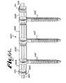
- FIG. 9is a perspective view of a second embodiment of a dynamic fixation longitudinal connecting member according to the invention shown with three bone screws.
- FIG. 10is an enlarged perspective view of a rigid rod portion of the connecting member of FIG. 9 .
- FIG. 11is an enlarged perspective view of three rigid rod portions and connecting inner core ties of the connecting member of FIG. 9 .
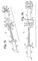
- FIG. 12is a front elevational view of a third embodiment of a dynamic fixation longitudinal connecting member according to the invention including first and second rigid rod portions, an inner core, an outer spacer, an elastic bumper and a crimping ring, and shown attached to a pair of polyaxial bone screws.
- FIG. 13is an enlarged perspective view of the first rigid rod portion of FIG. 12 .
- FIG. 14is an enlarged perspective view of the second rigid rod portion of FIG. 12 .
- FIG. 15is an enlarged exploded perspective view of the connecting member of FIG. 12 , the spacer having a portion broken away to show the detail thereof.
- FIG. 16is an enlarged exploded front elevational view of the connecting member of FIG. 12 , the spacer having a portion broken away to show the detail thereof.
- FIG. 17is an enlarged front elevational view of the connecting member of FIG. 12 with portions broken away to show the detail thereof.
- FIG. 18is an enlarged side elevational view of the spacer shown in FIG. 12 .
- FIG. 19is an opposed side elevational view of the spacer of FIG. 18 .
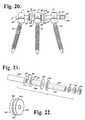
- FIG. 20is a front elevational view of a fourth embodiment of a dynamic fixation longitudinal connecting member according to the invention shown with three bone screws.
- FIG. 21is an enlarged exploded perspective view of rigid rod portions, a bumper and a crimping ring of the connecting member of FIG. 20 .
- FIG. 22is an enlarged perspective view of one of the spacers of the connecting member of FIG. 20 .
- FIG. 23is a front elevational view of a fifth embodiment of a dynamic fixation longitudinal connecting member according to the invention, similar to that shown in FIG. 20 , but including an additional spacer.
- FIG. 24is a front elevational view of a sixth embodiment of a dynamic fixation longitudinal connecting member according to the invention, also similar to that shown in FIG. 20 , but including an additional spacer and bumper.
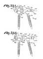
- FIG. 25Ais a front elevational view of a seventh embodiment of a dynamic fixation longitudinal connecting member according to the invention, shown in a first state or position.
- FIG. 25Bis another front elevational view of the seventh embodiment of a dynamic fixation longitudinal connecting member according to the invention, shown in a second state or position.
- FIG. 26Ais another front elevational view of the embodiment shown in FIGS. 25A and B, showing the embodiment in another state or position.
- FIG. 26Bis another front elevational view of the embodiment shown in FIGS. 25A and B and 26 A, showing the embodiment in another state or position.
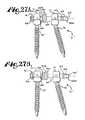
- FIG. 27Ais a front elevational view of an eighth embodiment of a dynamic fixation longitudinal connecting member according to the invention, shown in a first state or position.
- FIG. 27Bis a front elevational view of the eighth embodiment of a dynamic fixation longitudinal connecting member according to the invention, shown in a second state or position.
- FIG. 28is a partial perspective view of another soft dynamic stabilization connector of the invention having an inner cord, an outer spacer, an elastic bumper and a fixing structure or blocker, shown as a crimping structure, the connector shown with a pair of open monoaxial bone screws, one with a cord travel or sliding closure top and one with a cord compressing and locking closure top.
- FIG. 29is a partial and reduced and exploded front elevational view of the connector and bone screws of FIG. 28 , shown without the closure tops.
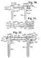
- FIG. 30is a partial front elevational view, similar to FIG. 29 showing a stage of assembly of the connector and bone screws of FIG. 28 , showing use of a driving tool for fixing one of the first closure tops against the cord.
- FIG. 31is a partial top plan view with portions broken away to show the detail thereof, showing use of a crimping tool in a further stage of assembly of the connector and bone screws of FIG. 28 .
- FIG. 32is an enlarged and partial cross-sectional view taken along the line 32 - 32 of FIG. 28 .
- FIG. 33is an exploded perspective view of an alternative bone screw for use with the invention of FIG. 28 , shown with a cord and a cord sliding limited travel closure top.
- FIG. 34is a partial perspective view of an alternative bar for use with the bone screw and closure top of FIG. 33 .
- FIG. 35is an enlarged and partial cross-sectional view of the bone screw of FIG. 33 taken along the line 35 - 35 of FIG. 33 and showing a portion of the cord in phantom.
- FIG. 36is an enlarged and partial cross-sectional view taken along the line 36 - 36 of FIG. 35 and also showing the mated closure top in cross section, a portion of the cord in phantom and an alternative closure top possibility, such top having an upper cap or stop shown in phantom.
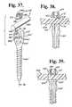
- FIG. 37is an exploded perspective view of the bone screw of FIG. 33 shown with a second locking closure top and a deformable rod.
- FIG. 38is a partial cross-sectional view taken along the line 38 - 38 of FIG. 37 and showing the second locking closure top in an early stage of assembly.
- FIG. 39is a partial cross-sectional view, similar to FIG. 38 , showing the second closure top fully assembled within the bone screw and engaged with and compressing a deformable rod.
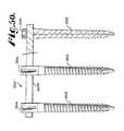
- FIG. 40is an enlarged and partial cross-sectional view of the bone screw of FIG. 37 taken along the line 38 - 38 , with a portion of the deformable rod being shown in phantom.
- FIG. 41is an enlarged and partial cross-sectional view, taken along the line 41 - 41 of FIG. 40 , also showing the mated closure top and a portion of the deformable rod in cross-section.
- FIG. 42is a perspective view of another alternative embodiment of a soft dynamic stabilization connector of the invention having an inner rod, an elastic bumper and a blocking structure, the connector shown with a pair of open polyaxial bone screws.
- FIG. 43is an enlarged and partial side elevational view of one of the bone screws of the embodiment of FIG. 42 with portions broken away to show the detail thereof and also showing an alternative cap portion in phantom.
- FIG. 44is a front elevational view of another soft dynamic stabilization connector of the invention having an inner cord, an elastic bumper and a blocking structure, two spacers and shown with three open monoaxial screws and cooperating closure tops.
- FIG. 45is another front elevational view of the connector of FIG. 44 with portions broken away to show the detail thereof.
- FIG. 46is another front elevational view of the connector of FIG. 44 shown in a compressed state.
- FIG. 47is a front elevational view of the connector of FIG. 46 with portions broken away to show the detail thereof.
- FIG. 48is another front elevational view of the connector of FIG. 44 shown in a distracted state.
- FIG. 49is a front elevational view of the connector of FIG. 48 with portions broken away to show the detail thereof.
- FIG. 50is a front elevational view with portions broken away to show the detail thereof of a replacement assembly wherein the soft cord, blocker, bumper and spacers of the connector of FIG. 44 have been removed and replaced with a hard rod.
- FIG. 51is a front elevational view of another soft dynamic stabilization connector of the invention having an inner cord, an elastic bumper and a blocking structure, a spacer, a rod/cord connector, a rod and shown with four open monoaxial screws and cooperating closure tops.
- FIG. 52is another front elevational view of the connector of FIG. 51 with portions broken away to show the detail thereof.
- FIG. 53is a front elevational view of another soft dynamic stabilization connector of the invention having an inner cord, an elastic bumper and a blocking structure, two lordotic spacers, and shown with three open monoaxial screws and cooperating closure tops.
- FIG. 54is another front elevational view of the connector of FIG. 53 with portions broken away to show the detail thereof.
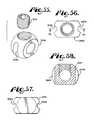
- FIG. 55is an enlarged, exploded and perspective view of the blocker and cooperating set screw shown in FIG. 44 .
- FIG. 56is a top plan view of the blocker of FIG. 55 .
- FIG. 57is a bottom plan view of the blocker of FIG. 55 .
- FIG. 58is a cross-sectional view taken along the line 58 - 58 of FIG. 56 .
- FIG. 59is an enlarged perspective view of one of the spacers shown in FIG. 44 .
- FIG. 60is a reduced, exploded, perspective view of one of the open bone screws shown in FIG. 44 , shown with both a slip and a grip closure top.
- FIG. 61is an enlarged, exploded perspective view of the rod/cord connector and cooperating set screws shown in FIG. 51 .
- FIG. 62Ais a partial and enlarged front elevational view of another soft dynamic stabilization connector of the invention having an inner cord, an elastic bumper and a blocking structure, two spacers and shown, with three closed monoaxial screws, one with a cooperating set screw, the figure shows the connector in a distracted state.
- FIG. 62Bis a partial and enlarged front elevational view, similar to FIG. 62A , showing the connector of FIG. 62A in a compressed state.
- FIG. 62Cis a partial and enlarged front elevational view, similar to FIG. 62A , showing the connector of FIG. 62A in a nominal state.
- FIG. 63Ais a partial front elevational view with portions broken away of the connector of FIG. 62A .
- FIG. 63Bis a partial front elevational view with portions broken away of the connector of FIG. 62B .
- FIG. 63Cis a partial front elevational view with portions broken away of the connector of FIG. 62C .
- FIG. 64is a front elevational view of another soft dynamic stabilization connector of the invention having an inner cord, two elastic bumpers, two blocking structures, two spacers and shown with three closed monoaxial screws with no set screws.
- FIG. 65is a partial front elevational view with portions broken away of the connector of FIG. 64 .
- FIG. 66is a partial front elevational view of another soft dynamic stabilization connector of the invention having an inner cord, one elastic bumper, two blocking structures, one having a break-off head, two spacers and shown with three closed monoaxial screws with no set screws.
- FIG. 67is another partial front elevational view of the connector of FIG. 66 , showing the spacer compressed and the blocking structure break-off head removed.
- FIG. 68is a partial front elevational view with portions broken away of the connector of FIG. 67 .
- FIG. 69is a reduced, exploded, perspective view of the closed bone screw and cooperating set screw shown in FIGS. 62A-68 .
- FIG. 70is an exploded side elevational view of the bone screw and set screw of FIG. 69 .
- FIG. 71is an enlarged side elevational view of the bone screw of FIG. 70 with portions broken away to show the detail thereof.
- the reference numeral 1generally designates a non-fusion dynamic stabilization longitudinal connecting member assembly according to the present invention.
- the connecting member assembly 1is elongate and substantially cylindrical, having a central axis A.
- the connecting member assembly 1generally includes first and second substantially rigid members 6 and 7 with a central, dynamic connection or transition portion or segment, generally 8 , disposed therebetween.
- a tie or a plurality of ties 10link the rigid members 6 and 7 at the central segment 8 .
- the ties 10may be any flexible elongate material that fastens, secures or unites the rigid members 6 and 7 , including, but not limited to cords, threads, strings, bands, or fibers that may be single or multiple strands, including twisted, braided or plaited materials.
- the illustrated central segment 8further includes an outer sleeve or spacer 14 and a pair of support rings 16 .
- Each of the illustrated rigid members 6 and 7are substantially cylindrical with one or more circular cross-sections along a length thereof. However, it is foreseen that the members 6 and 7 may have other forms, including but not limited to oval, square and rectangular cross-sections as well as other curved or polygonal shapes. It is foreseen that the member 6 and 7 may be of different materials, different shapes or different sizes, and thus one member may be more rigid or more flexible than the other member.
- the members 6 and 7each are of a length for cooperating with at least one and up to a plurality of bone attachment members, such as bone screws or hooks.
- the member 6is substantially solid, rigid and cylindrical and further includes a buttress or plate 20 having a plurality of apertures in the form of through bores 22 .
- the member 7is also substantially solid, rigid and cylindrical and includes a buttress or plate 24 similar or identical to the plate 20 .
- the plate 24also has a plurality of apertures in the form of through bores 26 running therethrough that are identical or similar to the apertures 22 .
- Each of the bores 22 and 26extends through the respective plate 20 and 24 at an oblique angle with respect to the axis A. It is foreseen that according to the invention the bores 22 and 26 may also run parallel to the axis A. It is foreseen that the cord, cords, strands or fibers could be embedded into or adhered on the ends of the members 6 and 7 .
- the ties 10are in the form of six independent closed loops, 10 a , 10 b , 10 c , 10 d , 10 e and 10 f , oriented in a cris-cross pattern, that attach or tether the rigid members 6 and 7 together at the respective plates 20 and 24 .
- the loopsare installed individually, with the individual cords 10 being at least one of knotted, adhered, bonded or melted, to form such a closed loop after threading though two adjacent bores in each of the plates 20 and 24 .
- one looped cord 10extends through the bores 22 a and 22 b , looping about the plate 20 at a location between the bores 22 a and 22 b , and also extends through the bores 26 d and 26 e , looping about the plate 24 at a location between the bores 26 d and 26 e .
- cord 10While, in similar fashion, another cord 10 loops about the plate 22 by extending through the bores 22 d and 22 e and also about the plate 24 by extending through the bores 26 a and 26 b .
- orienting the individual loops 10 a - 10 f in such a cris-cross patternprovides a resulting dynamic corded section 8 that slopes or angles inwardly toward the axis A at or near a central location 28 thereof, providing adequate clearance and ready acceptance of the spacer 14 as will be described in greater detail below.
- the cords 10may be individually looped in a configuration substantially parallel to the axis A or a variety of other orientations.
- the ties 10 making up the individual or closed loopsmay be made from a variety of materials, including polyester or other plastic fibers, strands or threads, such as polyethylene-terephthalate. Such cord and cord-like materials usually are placed under axial tension prior to final installation, for example, the loops 10 a - 10 f that are attached to the plates 20 and 24 may be tensioned along the axis A for a selected time prior to installation of the spacer 14 to allow the cords 10 to lengthen and otherwise deform during a primary creep stage.
- cords 10after the cords 10 reach secondary or steady-state creep, further tension is then placed on the cords 10 in preparation for installation of the spacer 14 between the plates 20 and 24 to ensure dynamic pre-loading of the connector 1 , with the corded loops 10 a - 10 f being in tension along the axis A while at the same time the spacer 14 is in compression along the axis A.
- greater or fewer than six discrete loops or even a single tie 10may be laced through numerous apertures in the plates 20 and 24 to connect the member 6 to the member 7 .
- Cords 10 of the inventiontypically do not illustrate elastic properties, such as any significant additional axial distraction after the assembly 1 is operatively assembled.
- the ties or cords 10may be made of a plastic or rubber (natural or synthetic) having elastic properties, allowing for some further distraction of the central connection portion 8 at the ties 10 during operation thereof.
- each of the plates 20 and 24include respective outer planar surfaces or faces 30 and 34 that operatively face toward one another. Furthermore, each plate 20 and 24 has a respective opposed face 36 and 38 .
- the bores 22 a - fopen at both the faces 30 and 36 and the bores 26 a - f open at both the faces 34 and 38 .
- the cords 10that form the six discrete closed loops, contact the faces 36 and 38 and attach the plate 20 to the plate 24 with the substantially planar surfaces 30 and 34 facing each other. Extending from the faces 36 and 38 are respective elongate cylindrical portions 40 and 42 of the rigid members 6 and 7 .
- the portion 40terminates at an end 44 and the portion 42 terminates at an end 46 .
- the portions 40 and 42are each sized and shaped to attach to at least one bone anchor as will be described in greater detail below.
- the illustrated portions 40 and 42are approximately the same size, but it is foreseen that different sizes, lengths and shapes are possible, as well as making the portions 40 and 42 from different materials and also making the plates 20 and 24 from materials that are different than the portions 40 and 42 .
- the plates 20 and 24are integral with respective elongate portions 40 and 42 with the members 6 and 7 being made from metal, metal alloys or other suitable materials, including plastic polymers such as polyetheretherketone (PEEK), ultra-high-molecular weight-polyethylene (UHMWP), polyurethanes and composites, including composites containing carbon fiber.
- PEEKpolyetheretherketone
- UHMWPultra-high-molecular weight-polyethylene
- polyurethanespolyurethanes
- compositesincluding composites containing carbon fiber.
- the sleeve or spacer 14advantageously cooperates with the cords 10 of the central connection or transition portion 8 , providing limitation and protection of movement of the cords 10 .
- the spacer 14also protects patient body tissue from damage that might otherwise occur in the vicinity of the corded central portion 8 .
- the spacer 14is substantially cylindrical and made from a plastic, such as a thermoplastic elastomer made from a polyurethane or polyurethane blend.
- the spacer 14has an external substantially cylindrical outer surface 50 and an internal surface 52 defining a through bore.
- the internal surface 52is further defined by a centrally located surface 53 having a circular cross section and a pair of outwardly extending substantially conical surfaces 56 and 57 running from the surface 53 to respective substantially planar end surfaces 60 and 62 .
- the end surfaces 60 and 62are substantially perpendicular to the axis A and the cris-cross orientation of the looped cords 10 follow the conical inner surfaces 56 and 57 of the spacer 14 with the central portion 28 of the looped cords being substantially aligned with the inner surface 53 .
- the spacermay be of circular, square, rectangular or other cross-section including curved or polygonal shapes.
- the spacer 14further includes a compression groove 64 and a pair of grooves 66 on either side of the groove 64 sized and shaped to receive the support rings or bands 16 .
- Spacers according to the inventionmay include one, none or any desired number of grooves.
- the illustrated grooves 64 and 66are substantially uniform and circular in cross-section, being formed in the external surface 50 and extending radially toward the internal surface 52 .
- the size of the internal surface 52allows for some axially directed sliding movement of the spacer 14 with respect to the cords 10 of the section 8 .
- the spacer 14further includes a radially directed elongate slit or gap opening 68 extending therethrough between the outer surface 50 and the inner surface 52 and through the end surfaces 60 and 62 .
- the slit or gap 68allows for opening the spacer 14 and placing the spacer 14 onto the cords 10 of the section 8 with the gap or slit 68 widening or expanding to receive the cords 10 and then elastically returning the spacer 14 to an original cylindrical shape as shown in FIG. 8 , but now positioned with the inner cylindrical surface 52 in sliding, rotating engagement with the cords 10 of the section 8 . Also, as shown in FIG. 8 , when the spacer 14 is initially placed on the cords 10 , the spacer 14 completely surrounds the cords 10 and abuts against the buttress plate surfaces 30 and 34 . The cords 10 and cooperating compressible spacer 14 allows for some twist or turn, providing some relief for torsional stresses.
- the spacer 14limits such torsional movement as well as bending movement, providing spinal support, as well as allowing for further compression of the assembly 1 at the transition segment 8 . It is noted that in addition to limiting the bendability of the central connection portion 8 and thus providing strength and stability to the assembly 1 , the spacer 14 also keeps scar tissue from growing into the portion 8 through the cords 10 , thus eliminating the need for a sheath-like structure to be placed, adhered or otherwise applied to the cords 10 on the central connection portion 8 .
- the spacer 14 inner surfaces and/or cooperating cord 10 surfacesmay be coated with an ultra thin, ultra hard, ultra slick and ultra smooth coating, such as may be obtained from ion bonding techniques and/or other gas or chemical treatments.
- the support rings or bands 16are annular and sized and shaped to encircle the spacer 14 and be closely received in the grooves 66 .
- Support rings 16may be made from a variety of materials, including metals, metal alloys and plastics. A preferred material is tantalum.
- the rings 16are of circular cross-section and each include a slit or gap 70 . The slit or gap 70 allows for opening the ring 16 and placing the ring 16 about the spacer 14 and into one of the grooves 66 with the gap or slit 70 widening or expanding to receive the spacer 14 and then elastically returning the ring 16 to an original circular orientation as shown in FIG.
- the support rings or bandsmay be made of a tough elastic material and therefore not require the slit 70 .
- the member 6 or 7During installation, the member 6 or 7 would be received by such a band and then the band would be stretched about the spacer 14 and allowed to return to its original form in one of the grooves 66 .
- a preferred connector 1 of the inventionwherein the members 6 and 7 are made from PEEK and cooperate with polyethylene cords 10 and a polyurethane spacer 14 , an assembly 1 that is radiolucent results.
- the dynamic connecting member assembly 1cooperates with at least a pair of bone anchors, such as polyaxial bone screws, generally 75 , and cooperating closure structures 77 shown in FIG. 1 , the assembly 1 being captured and fixed in place at the rigid end portions 40 and 42 by cooperation between the bone screws 75 and the closure structures 77 .
- the dynamic section 8that is pre-loaded and pre-tensioned, is disposed between the bone screws 75 .
- an advantageous connecting member 1includes a portion 42 made from a metal alloy such as stainless steel that is elongate and intended for fusion along a major portion or section of the spine, for example, the portion 42 may be sized to extend from the sacrum to the thoracic spinal segment T 10 .
- Such an elongate portion 42is thus connectable to a plurality of bone anchors along the spine.
- Such a connecting memberfurther includes a dynamic section 8 , having cords 10 and spacer 14 that is sized for placement, for example, between T 9 and T 8 .
- Such an embodimentis believed to minimize rapid degeneration and compressive fractures that tend to occur near ends of such elongate connecting member assemblies.
- the connecting member assembly 1may be used with a wide variety of bone anchors already available for cooperation with rigid rods including fixed, monoaxial bone screws, hinged bone screws, polyaxial bone screws, and bone hooks and the like, with or without compression inserts, that may in turn cooperate with a variety of closure structures having threads, flanges, or other structure for fixing the closure structure to the bone anchor, and may include other features, for example, break-off tops and inner set screws.
- the bone anchors, closure structures and the connecting member assembly 1are then operably incorporated in an overall spinal implant system for correcting degenerative conditions, deformities, injuries, or defects to the spinal column of a patient.
- the illustrated polyaxial bone screws 75each include a shank 80 for insertion into a vertebra (not shown), the shank 80 being pivotally attached to an open receiver or head 81 .
- the shank 80includes a threaded outer surface and may further include a central cannula or through-bore disposed along an axis of rotation of the shank to provide a passage through the shank interior for a length of wire or pin inserted into the vertebra prior to the insertion of the shank 80 , the wire or pin providing a guide for insertion of the shank 80 into the vertebra.
- the receiver 81has a pair of spaced and generally parallel arms 85 that form an open generally U-shaped channel therebetween that is open at distal ends of the arms 85 .
- the arms 85each include radially inward or interior surfaces that have a discontinuous guide and advancement structure mateable with cooperating structure on the closure structure 77 .
- the guide and advancement structuremay take a variety of forms including a partial helically wound flangeform, a buttress thread, a square thread, a reverse angle thread or other thread like or non-thread like helically wound advancement structure for operably guiding under rotation and advancing the closure structure 77 downward between the receiver arms 85 and having such a nature as to resist splaying of the arms 85 when the closure 77 is advanced into the U-shaped channel.
- a flange form on the illustrated closure 77 and cooperating structure on the arms 85is disclosed in Applicant's U.S. Pat. No. 6,726,689, which is incorporated herein by reference.
- the shank 80 and the receiver 81may be attached in a variety of ways.
- a spline capture connectionas described in Applicant's U.S. Pat. No. 6,716,214, and incorporated by reference herein, may be used for the embodiment disclosed herein.
- Polyaxial bone screws with other types of capture connectionsmay also be used according to the invention, including but not limited to, threaded connections, frictional connections utilizing frusto-conical or polyhedral capture structures, integral top or downloadable shanks, and the like.
- polyaxial and other bone screws for use with connecting members of the inventionmay have bone screw shanks that attach directly to the connecting member portion or segment 40 or 42 , or may include compression members or inserts that cooperate with the bone screw shank, receiver and closure structure to secure the connecting member assembly 1 to the bone screw and/or fix the bone screw shank at a desired angle with respect to the bone screw receiver that holds the longitudinal connecting member assembly 1 .
- the connecting member portions 40 and 42are fabricated from a plastic such as polyetheretherketone (PEEK), it may be desirable to utilize bone screws that include one or both upper and lower compression inserts that have a saddle or U-shape configuration to closely engage such segments within the bone screw receiver.
- closure structure 77 of the present inventionis illustrated with the polyaxial bone screw 75 having an open receiver or head 81 , it is also foreseen that a variety of closure structures may be used in conjunction with any type of medical implant having an open or closed head, including monoaxial bone screws, hinged bone screws, hooks and the like used in spinal surgery.
- the threaded shank 80may be coated, perforated, made porous or otherwise treated.
- the treatmentmay include, but is not limited to a plasma spray coating or other type of coating of a metal or, for example, a calcium phosphate; or a roughening, perforation or indentation in the shank surface, such as by sputtering, sand blasting or acid etching, that allows for bony ingrowth or ongrowth.
- Certain metal coatingsact as a scaffold for bone ingrowth.
- Bio-ceramic calcium phosphate coatingsinclude, but are not limited to: alpha-tri-calcium phosphate and beta-tri-calcium phosphate (Ca 3 (PO 4 ) 2 , tetra-calcium phosphate (Ca 4 P 2 O 9 ), amorphous calcium phosphate and hydroxyapatite (Ca 10 (PO 4 ) 6 (OH) 2 ).
- Coating with hydroxyapatitefor example, is desirable as hydroxyapatite is chemically similar to bone with respect to mineral content and has been identified as being bioactive and thus not only supportive of bone ingrowth, but actively taking part in bone bonding.
- the closure structure 77can be any of a variety of different types of closure structures for use in conjunction with the present invention with suitable mating structure on the interior surface of the upstanding arms 85 of the receiver 81 .
- the illustrated closure structure 77is rotatable between the spaced arms 85 , but could be a slide-in closure structure.
- the illustrated closure structure 77is substantially cylindrical and includes an outer helically wound guide and advancement structure in the form of a flange form 88 that operably joins with the guide and advancement structure disposed on the interior of the arms 85 .
- the illustrated closure structure 77includes a lower or bottom surface that is substantially planar and may include a point and/or a rim protruding therefrom for engaging the portion 40 or 42 outer cylindrical surface.
- the closure structure 77has a top surface 90 with an internal drive feature 92 , that may be, for example, a star-shaped drive aperture sold under the trademark TORX.
- a driving tool(not shown) sized and shaped for engagement with the internal drive feature 92 is used for both rotatable engagement and, if needed, disengagement of the closure 77 from the arms 85 .
- the tool engagement structure 92may take a variety of forms and may include, but is not limited to, a hex shape or other features or apertures, such as slotted, tri-wing, spanner, two or more apertures of various shapes, and the like. It is also foreseen that the closure structure 77 may alternatively include a break-off head designed to allow such a head to break from a base of the closure at a preselected torque, for example, 70 to 140 inch pounds. Such a closure structure would also include a base having an internal drive to be used for closure removal.
- each vertebramay be pre-drilled to minimize stressing the bone.
- each vertebrawill have a guide wire or pin (not shown) inserted therein that is shaped for the bone screw cannula of the bone screw shank 80 and provides a guide for the placement and angle of the shank 80 with respect to the cooperating vertebra.
- a further tap holemay be made and the shank 80 is then driven into the vertebra by rotation of a driving tool (not shown) that engages a driving feature on or near a top portion of the shank 80 . It is foreseen that the screws 75 and the longitudinal connecting member assembly 1 can be inserted in a percutaneous or minimally invasive surgical manner.
- the longitudinal connecting member assembly 1is factory assembled to include the looped ties 10 that are initially tensioned to steady state and thereafter further tensioned to receive the spacer 14 that is cut to a desired size so that the spacer 14 is axially compressed between the plates 20 and 24 after insertion of the spacer 14 about the cords or ties 10 and between such plates 20 and 24 .
- the spacer 14is opened or expanded at the slit 68 and moved into position over the cords 10 of the central portion 8 and between the plates 20 and 24 and then allowed to elastically return to an original cylindrical form as shown in FIG. 8 .
- the spacer 14is also axially compressed during insertion such that the spacer 14 easily slides and is received between the surfaces 30 and 34 . Thereafter, the rings or bands 16 are expanded at the respective slits 70 and moved into position in the grooves 66 , followed by spot welding thereof to result in closed rings 16 encircling the spacer 14 .
- the resulting connecting member assembly 1is thus dynamically loaded with the cords 10 in tension and the spacer 14 in compression.
- the pre-loaded connecting member assembly 1is eventually positioned in an open or percutaneous manner in cooperation with the at least two bone screws 75 with the cords 10 and the spacer 14 disposed between and spaced from the two bone screws 75 and with the portions 40 and 42 each being within a U-shaped channel of a cooperating bone screw 75 . It is noted that the portions 40 and/or 42 near respective ends 44 and 46 may be selectively trimmed or cut to size before or at the time of surgery, or if longer, attached to the spine with additional bone anchors. Once a desired position is attained, a closure structure 77 is then inserted into and advanced between the arms 85 of each of the bone screws 75 .
- the closure structure 77is rotated, using a tool (not shown) engaged with the inner drive 92 until a selected pressure is reached at which point the section 40 or 42 is urged toward, but not completely seated in the U-shaped channel of the bone screw 75 .
- a selected pressureFor example, about 80 to about 120 inch pounds pressure may be required for fixing the bone screw shank 80 with respect to the receiver 81 at a desired angle of articulation.
- the assembly 1is thus substantially dynamically loaded and oriented relative to the cooperating vertebra, providing relief (e.g., shock absorption) and protected movement with respect to flexion, extension, distraction and compressive forces placed on the assembly 1 and the two connected bone screws 75 .
- the looped cords 10 and the spacer 14allow for some twisting or turning, providing some relief for torsional stresses.
- the compressed spacer 14places some limits on torsional movement as well as bending movement, to provide spinal support.
- the pre-loaded cords 10 (in tension) and spacer 14 (in compression)allow for compression and some extension of the assembly 1 located between the two bone screws 75 , e.g., shock absorption.
- disassemblyis accomplished by using the driving tool (not shown) with a driving formation cooperating with the closure structure 77 internal drive 92 to rotate and remove the closure structure 77 from the receiver 81 . Disassembly is then accomplished in reverse order to the procedure described previously herein for assembly.
- the connecting member assembly 1may be removed and replaced with another longitudinal connecting member, such as a solid rod, having the same diameter as the portions 40 and 42 , utilizing the same receivers 81 and the same or similar closure structures 77 .
- another longitudinal connecting membersuch as a solid rod
- a less rigid, more flexible assemblyfor example, an assembly 1 having portions 40 and 42 made of a more flexible material, but with the same diameter as the rigid portions 40 and 42 , may replace the assembly 1 , also utilizing the same bone screws 75 .
- an alternative longitudinal connecting member assemblyhas a central axis B and includes rigid members 105 , 106 and 107 and first and second dynamic connection portions or sections 108 and 108 A.
- the dynamic sections 108 and 108 Ainclude respective closed looped cords 110 and 110 A, respective spacers 114 and 114 A and respective support rings 116 and 116 A.
- the connecting member assembly 101provides for two dynamic support sections between a plurality of vertebrae.
- the illustrated embodimentis shown attached to three bone screws 75 and cooperating closure structures 77 previously described herein.
- the illustrated rigid members 105 , 106 and 107are each sized for attachment to a single bone anchor or screw.
- each such rigid member 105 , 106 and 107may be of greater length (along the axis B) for operative attachment to two or more bone anchors. Furthermore, more than one rigid member 105 may be disposed between rigid members 106 and 107 to provide a plurality of dynamic sections.
- the illustrated members 106 and 107are identical or substantially similar to respective members 6 and 7 previously described herein with respect to the connecting member 1 , the member 106 having an end plate 120 and a plurality of bores 122 similar to the plate 20 and bores 22 previously described herein and the member 107 having an end plate 124 and a plurality of bores 126 similar to the plate 24 and bores 26 previously described herein with respect to the member 7 .
- the closed looped cords 110 and 110 Aare identical or substantially similar to the closed looped cords 10 previously described herein with respect to the connecting member 1 with the cooperating spacers 114 and 114 A being identical or substantially similar to the spacer 14 previously described herein with respect to the connecting member 1 .
- the support rings 116 and 116 Aare identical or substantially similar to the support rings 16 previously described herein with respect to the connecting member 1 .
- the connecting member 101rather than having closed looped cords that directly attach the members 106 and 107 as previously described with respect to the members 6 and 7 , the closed looped cords 110 attach the member 105 with the member 106 and the closed looped cords 110 A attach the member 105 with the member 107 in a manner substantially identical to what has been described herein with respect to the close looped cords 10 of the connecting member 1 .
- the member 105may also be considered to be an extender member that is disposed between the members 106 and 107 and is attached to each of such members with the respective closed looped cords 110 and 110 A to provide an additional dynamic segment to the assembly 101 .
- the illustrated member 105includes a pair of opposed end plates 182 and 183 and an integral cylindrical mid-portion 184 extending therebetween.
- the end plates 182 and 183are identical or substantially similar to the plates 20 and 24 previously described herein with respect to the members 6 and 7 .
- the end plates 182 and 183include respective apertures or through bores 186 and 187 for receiving the respective closed looped cords 110 and 110 A.
- the illustrated embodimentthere are six bores 186 cooperating with the six bores 122 of the member 6 and six bores 187 for cooperating with the six bores 126 of the member 107 .
- the looped cords 110loop through the bores 122 and the bores 186 while the looped cords 110 A loop through the bores 126 and the bores 187 .
- the illustrated cylindrical mid-portion 184is sized to be received between arms 85 of at least one bone screw 75 .
- the closed looped cords 110 and 110 Aare installed in the same manner as previously described herein with respect to the closed looped cords 10 and the spacers 114 and 114 A and cooperating support rings 116 and 116 A are installed in the same manner as previously described herein with respect to the spacer 14 and the rings 16 .
- the pre-tensioned, pre-compressed connecting member 101is positioned in an open or percutaneous manner in cooperation with the at least three bone screws 75 with the cords 110 and 110 A and cooperating spacers 114 and 114 A each disposed between and spaced from such bone screws 75 and portions of the members 105 , 106 and 107 each being within a U-shaped channel of a cooperating bone screw 75 .
- a closure structure 77is then inserted into and advanced between the arms 85 of each of the bone screws 75 to capture and lock the connecting member 101 in a desired location and position along the spine. Disassembly, removal and replacement of the connecting member assembly 101 with a more or less rigid connecting member may be performed in a manner as previously described herein with respect to the connecting member assembly 1 .
- FIGS. 12-19another alternative longitudinal connecting member assembly according to the invention, generally 201 is elongate and substantially cylindrical, having a central axis C.
- the connecting member assembly 201generally includes a first rigid anchor member 206 and a second rigid terminal member 207 .
- a central, dynamic connection or transition portion or segment, generally 208is disposed between the members 206 and 207 .
- a tie, cord or a plurality of ties or cords 210loop about and through apertures of the anchor member 206 and extend through a bore in the terminal member 207 .
- the ties 210may be any flexible elongate material that fastens, secures or unites the rigid members 206 and 207 , including, but not limited to cords, threads, strings, bands, or fibers that may be single or multiple strands, including twisted, braided or plaited materials.
- the illustrated central segment 208further includes a closed, non-slitted outer sleeve or spacer 214 .
- the assembly 201further includes an elastic bumper 217 and a crimping ring 219 .
- Each of the illustrated rigid members 206 and 207are substantially cylindrical with one or more circular cross-sections along a length thereof. However, it is foreseen that the members 206 and 207 may have other forms, including but not limited to oval, square and rectangular cross-sections as well as other curved or polygonal shapes. It is foreseen that the members 206 and 207 may be of different materials, different shapes or different sizes, and thus one member may be more rigid or more flexible than the other member.
- the members 206 and 207each are of a length for cooperating with at least one and up to a plurality of bone attachment members, such as bone screws or hooks.
- the anchor member 206is substantially solid, rigid and cylindrical and further includes a buttress or plate 220 having a plurality of apertures in the form of through bores 222 .
- the member 206is identical or substantially similar to the member 6 previously described herein with respect to the connecting member assembly 1 .
- the illustrated anchor member 206has six bores 222 that extend through the plate 220 at an oblique angle with respect to the axis C as best shown in FIG. 17 . It is foreseen that according to the invention the bores 222 may also run parallel to the axis C.
- the ties or cords 210are in the form of six independent open loops installed individually by looping through pairs of adjacent bores 222 and then extending outwardly away from the plate 220 as shown in FIGS. 15 and 16 . Similar to the cords 10 discussed previously herein, the cords 210 are placed under axial tension along the axis C for a selected time prior to final, fixed installation with the other components 214 , 207 , 217 and 219 to lengthen and otherwise deform the cords 210 during a primary creep stage. After the cords 210 reach secondary or steady-state creep, further tension is then placed on the cords 210 in preparation for final tightening and crimping of the ring 219 as will be described in greater detail below. It is also foreseen that in alternative embodiments of the invention, greater or fewer than six discrete open loops may be laced through apertures in the plate 220 and pulled through the member 207 .
- the cords 210 of the inventiontypically do not illustrate elastic properties, such as any significant additional axial distraction after the assembly 201 is operatively assembled.
- the ties or cords 210may be made of a plastic or rubber (natural or synthetic) having elastic properties, allowing for some further distraction of the central connection portion 208 at the ties 210 during operation thereof.
- the terminal member 207includes a buttress or plate 224 and in inner surface 226 that forms a through bore extending through the entire member 207 in an axial direction, sized and shaped for receiving a length of the bundled cords 210 .
- the bore formed by the inner surface 226extends along the axis C.
- each of the plates 220 and 224include respective outer planar surfaces or faces 230 and 234 that operatively face toward one another.
- each plate 220 and 224has a respective opposed face 236 and 238 .
- the bores 222open at both the faces 230 and 236 .
- the inner surface 226 forming the bore of the member 207opens at the outer planar surface 234 and also at an end 239 .
- the cords 210 that form the discrete open loops, loop about and contact the face 236extend along the axis C within the inner surface 226 and extend through the end 239 .
- Extending from and integral to the faces 236 and 238are respective elongate cylindrical portions 240 and 242 of the respective anchor member 206 and the terminal member 207 .
- the portion 240terminates at an end 244 .
- the open cords 210extend completely through the elongate cylindrical portion 242 and into the bumper 217 and the crimping ring 219 .
- the portions 240 and 242are each sized and shaped to attach to at least one bone anchor as will be described in greater detail below.
- the illustrated portions 240 and 242are approximately the same size and length, but it is foreseen that different sizes, lengths and shapes are possible, as well as making the portions 240 and 242 from different materials and also making the plates 220 and 224 from materials that are different than the portions 240 and 242 .
- the plates 220 and 224are integral with respective elongate portions 240 and 242 with the members 206 and 207 being made from metal, metal alloys or other suitable materials, including plastic polymers such as polyetheretherketone (PEEK), ultra-high-molecular weight-polyethylene (UHMWP), polyurethanes and composites, including composites containing carbon fiber.
- PEEKpolyetheretherketone
- UHMWPultra-high-molecular weight-polyethylene
- compositesincluding composites containing carbon fiber.
- the sleeve or spacer 214advantageously cooperates with the cords 210 of the central connection or transition portion 208 , providing limitation and protection of movement of the cords 210 .
- the spacer 214also protects patient body tissue from damage that might otherwise occur in the vicinity of the corded central portion 208 .
- the spacer 214is substantially cylindrical and made from a plastic, such as a thermoplastic elastomer made from a polyurethane or polyurethane blend.
- the spacer 214has an external substantially cylindrical outer surface 250 and an internal surface 252 defining a through bore.
- the internal surface 252is further defined by a substantially cylindrical surface 253 having a circular cross section and an outwardly extending substantially conical surface 256 running from the surface 253 to a substantially planar end surface 260 .
- the spacer 214further includes an opposed planar end surface 262 .
- the inner cylindrical surface 253opens to the end surface 262 .
- the end surfaces 260 and 262 of the spacer 214are substantially perpendicular to the axis C. Also, when installed within the inner cylindrical surface 226 , the cords 210 are drawn inwardly from the bores 222 and toward the axis C.
- the conical inner surface 256 of the spacer 214provides clearance for the cords 210 at the plate surface 230 while the cylindrical inner surface 253 aligns the cords 210 with the inner bore formed by the inner surface 226 of the terminal member 207 . It is also foreseen that the cords 210 may be twisted or otherwise connected to form a substantially cylindrical unit prior to insertion in the spacer 214 and the terminal member 207 .
- the spacer 214may be of circular, square, rectangular or other cross-section including curved or polygonal shapes.
- the spacer 214further includes a compression groove 264 .
- Spacers according to the inventionmay include one, none or any desired number of grooves.
- the illustrated groove 264is substantially uniform and circular in cross-section, being formed in the external surface 250 and extending radially toward the internal surface 252 .
- the size of the internal surface 252allows for some axially directed sliding movement of the spacer 214 with respect to the cords 210 .
- the cords 210 and cooperating compressible spacer 214allow for some twist or turn, providing some relief for torsional stresses.
- the spacer 214limits such torsional movement as well as bending movement, providing spinal support, as well as allowing for further compression of the assembly 1 at the flexible central connection portion 208 . It is noted that in addition to limiting the bendability of the central connection portion 208 and thus providing strength and stability to the assembly 201 , the spacer 214 also keeps scar tissue from growing into the portion 208 through the cords 210 , thus eliminating the need for a sheath-like structure to be placed, adhered or otherwise applied to the cords 210 on the central connection portion 208 .
- the spacer 214 inner surfaces and/or cooperating cord 210 surfacesmay be coated with an ultra thin, ultra hard, ultra slick and ultra smooth coating, such as may be obtained from ion bonding techniques and/or other gas or chemical treatments.
- the bumper 217is substantially cylindrical, including an outer surface 270 and an inner surface 272 forming a substantially cylindrical through bore that opens at planar end surfaces 274 and 276 and operatively extends along the axis C.
- the bumper 217further includes a compression groove 278 that is similar in form and function to the compression groove 264 of the spacer 214 .
- the bumper 217is sized and shaped to receive the elongate cords 210 through the inner surface 272 .
- the bumper 217is preferably made from an elastomeric material such as polyurethane. The bumper 217 provides axial elastic distraction of the cords 210 as will be described in greater detail below.
- the crimping ring 219is substantially cylindrical and includes an outer surface 280 and an inner surface 282 forming a substantially cylindrical through bore that opens at planar end surfaces 284 and 286 and operatively extends along the axis C.
- the crimping ring 219is sized and shaped to receive the elongate cords 210 through the inner surface 282 .
- the crimping ring 219further includes a pair of crimp or compression grooves 288 that are pressable and deformable inwardly toward the axis C upon final tensioning of the cords 210 during assembly of the connector 201 to engage and hold the cords 210 in tension and thereby transmit compressive force to the elastic spacer 214 .
- the crimping ring 219is preferably made from a stiff, but deformable material, including metals and metal alloys.
- the cords 210may be threaded through two crimping rings 219 placed adjacent to one another, with a preliminary crimping ring being at a terminal end of the assembly 201 .
- a preliminary ringis crimped to initially lock the assembly together with the cords 210 in tension. If further creep and deformation of the cords 210 decreases the axial tension on the cords 210 within the assembly 201 , the cords 210 may be re-tensioned and locked into place with the second or final crimping ring.
- the preliminary crimping ringmay then be sliced off of the assembly 201 and discarded.
- the dynamic connecting member assembly 201cooperates with at least a pair of bone anchors, such as the polyaxial bone screws, generally 75 , and cooperating closure structures 77 described previously herein, the assembly 201 being captured and fixed in place at the rigid portions 240 and 242 by cooperation between the bone screws 75 and the closure structures 77 .
- the dynamic section 208that is pre-loaded and pre-tensioned, is disposed between the bone screws 75 .
- the longitudinal connecting member assembly 201is factory assembled by looping six ties 210 about and through the bores 222 of the plate 220 of the anchor member 207 to form the twelve strands or cords 210 that are then threaded through the remaining components of the assembly 201 .
- the ties 210may be initially tensioned to steady state and thereafter further tensioned after assembly with the other components.
- the twelve cords or strands 210 that are anchored to the member 206are initially passed through the spacer 214 inner surface 252 , followed by the terminal member 207 internal surface 226 , then the bumper 217 inner surface 272 and finally the crimping ring 219 inner surface 282 and out the end 286 .
- the spacer 214 , the terminal member 207 , the bumper 217 and the crimping ring 219are snugged up against the plate 220 of the anchor member 206 and tension is applied to the bundle of twelve cords 210 .
- Tensionis increased on the cord bundle 210 until the elastic spacer 214 and the elastic bumper 217 are compressed and the cords 210 have stopped stretching.
- the crimping ring 219is crimped using a tool (not shown) that presses on the opposed grooves 288 and deforms toward the axis C to make contact and firmly grip the cords 210 , keeping the cords 210 in the desired tension and locking the components of the assembly 201 in place.
- the resulting connecting member assembly 201is thus dynamically loaded with the cords 210 in tension and the spacer 214 and elastic bumper 217 in compression.
- the pre-loaded connecting member assembly 201is eventually positioned in an open or percutaneous manner in cooperation with the at least two bone screws 75 with the spacer 214 disposed between and spaced from the two bone screws 75 and with the portions 240 and 242 each being within a U-shaped channel of a cooperating bone screw 75 .
- a closure structure 77is then inserted into and advanced between the arms 85 of each of the bone screws 75 .
- the closure structure 77is rotated, using a tool (not shown) engaged with the inner drive 92 until a selected pressure is reached at which point the section 240 or 242 is urged toward, but not completely seated in the U-shaped channel of the bone screw 75 .
- a selected pressureis reached at which point the section 240 or 242 is urged toward, but not completely seated in the U-shaped channel of the bone screw 75 .
- about 80 to about 120 inch pounds pressuremay be required for fixing the bone screw shank 80 with respect to the receiver 81 at a desired angle of articulation.
- the assembly 201is thus substantially dynamically loaded and oriented relative to the cooperating vertebra, providing relief (e.g., shock absorption) and protected movement with respect to flexion, extension, distraction and compressive forces placed on the assembly 201 and the two connected bone screws 75 .
- the looped cords 210 and the spacer 214allow for some twisting or turning, providing some relief for torsional stresses.
- the compressed spacer 214places some limits on torsional movement as well as bending movement, to provide spinal support.
- the pre-loaded cords 210 (in tension) and spacer 214 (in compression)allow for compression and some extension of the assembly 201 located between the two bone screws 75 , e.g., shock absorption.
- Disassembly, removal and replacement of the connecting member assembly 201 with a more or less rigid connecting membermay be performed in a manner as previously described herein with respect to the connecting member assembly 1 .
- another longitudinal connecting member assemblyhas a central axis D and includes an intermediate rigid member 305 , a rigid anchor member 306 , a rigid terminal member 307 and first and second dynamic connection portions or sections 308 and 308 A.
- An open loop cord bundle 310extends through both the sections 308 and 308 A.
- the dynamic sections 308 and 308 Afurther include respective spacers 314 and 314 A.
- the connecting member assembly 301provides for two dynamic support sections between a plurality of vertebrae.
- the illustrated embodimentis shown attached to three bone screws 75 and cooperating closure structures 77 previously described herein.
- the illustrated rigid members 305 , 306 and 307are each sized for attachment to a single bone anchor or screw.
- each such rigid member 305 , 306 and 307may be of greater length (along the axis D) for operative attachment to two or more bone anchors.
- more than one rigid member 305may be disposed between rigid members 306 and 307 to provide a plurality of dynamic sections.
- the connecting member assembly 301is substantially similar to the connecting member assembly 201 previously described herein with the exception of three components: the additional intermediate rigid member 305 , the additional spacer 314 A and the additional crimping ring 319 A.
- the illustrated members 306 and 307are identical or substantially similar to respective members 206 and 207 previously described herein with respect to the connecting member 201 , the member 306 having an end plate 320 and a plurality of bores 322 similar to the plate 220 and bores 222 previously described herein and the member 307 having an end plate 324 and a through bore 326 similar to the plate 224 and bore 226 previously described herein with respect to the member 207 .
- the open looped cord bundle 310is identical or substantially similar to the open looped cord bundle 210 , with the exception that the bundle 310 is of greater axial length (along the axis D) as compared to the corded bundle 210 previously described herein with respect to the connecting member 201 .
- the spacer 314 that is disposed between the member 306 and the member 305is identical or substantially similar to the spacer 214 previously described herein with respect to the connecting member 201 .
- the elastic bumper 317 and both crimping rings 319 and 319 Aare identical or substantially similar to the respective bumper 217 and crimping ring 219 previously described herein with respect to the connecting member 201 .
- the intermediate rigid member 305is disposed between the members 306 and 307 and provides for an additional dynamic connection section 308 A.
- the member 301includes a pair of opposed end plates 382 and 383 and an integral cylindrical mid-portion 384 that extends therebetween.
- the end plates 382 and 383are identical or substantially similar to the plate 324 of the member 307 .
- the member 305further includes a through bore 386 running through the entire member 305 , from the end plate 382 to the end plate 383 and axially centrally through the cylindrical mid-portion 384 .
- the illustrated cylindrical mid-portion 384is sized to be received between arms 85 of at least one bone screw 75 .
- the spacer 314receives the cord bundle 310 at a location between the plate 320 of the anchor member 306 and the plate 382 of the intermediate rigid member 305 .
- the spacer 314 Areceives the cord bundle 310 at a location between the plate 383 of the member 305 and the plate 324 of the terminal member 307 .
- the illustrated spacer 314 Ais substantially similar to the spacer 314 and the spacer 214 previously described herein with respect to the connecting member assembly 201 , having an outer cylindrical surface 390 , an inner surface 392 defining a through bore running between planar surfaces 394 and 395 and at least one outer compression groove 396 .
- the inner surface 392 of the spacer 314 Ais cylindrical and defines a bore of constant circular cross-section sized and shaped to receive a length of the cord bundle 310 .
- the open looped cord bundle 310is installed on the anchor member 306 by looping through the apertures 322 in the same manner as previously described herein with respect to the installation of the open looped cord bundle 210 through the apertures 222 .
- the twelve cords or strands 310 that are anchored to the member 306are initially passed through the bore in the spacer 314 , followed by the bore formed by the intermediate member 305 internal cylindrical surface 386 , then the bore formed by the spacer 314 A internal surface 392 , followed by the bore formed by the terminal member 307 internal surface 326 , then the bore of the bumper 317 , the bore of the crimping ring 319 and finally through the bore of the crimping ring 319 A.
- the spacer 314 , the intermediate member 305 , the spacer 314 A, the terminal member 307 , the bumper 317 , the crimping ring 319 and the crimping ring 319 Aare snugged up against the plate 320 of the anchor member 306 and tension is applied to the bundle of twelve cords 310 .
- Tensionis increased on the cord bundle 310 until the elastic spacers 314 and 314 A and the elastic bumper 317 are compressed and the cords 310 have stopped stretching.
- the end crimping ring 319 Ais crimped using a tool (not shown) that presses on opposed grooves of the ring 319 A and deforms the ring toward the axis D to make contact and firmly grip the cords 310 .
- a toolnot shown
- the assembly 301may be re-tensioned by pulling the cords 310 away from the anchor member 306 until a desired tension is again reached.
- the other crimping ring 319is crimped using a tool (not shown) that presses on opposed grooves of the ring 319 and deforms the ring toward the axis D to make contact and firmly grip the cords 310 .
- the crimping ring 319 Ais sliced off of the assembly 301 .
- the resulting connecting member assembly 301is thus dynamically loaded with the cords 310 in tension with the spacers 314 and 314 A and the elastic bumper 317 in compression.
- the pre-loaded connecting member assembly 301is eventually positioned in an open or percutaneous manner in cooperation with the at least three bone screws 75 with the spacers 314 and 314 A disposed between and spaced from the bone screws 75 and with cylindrical portions of each of the members 305 , 306 and 307 being within a U-shaped channel of a cooperating bone screw 75 .
- a closure structure 77is then inserted into and advanced between the arms 85 of each of the bone screws 75 .
- the closure structure 77is rotated, using a tool (not shown) engaged with the inner drive 92 until a selected pressure is reached, for example, about 80 to about 120 inch pounds pressure may be required for fixing the bone screw shank 80 with respect to the receiver 81 at a desired angle of articulation.
- the assembly 301is thus substantially dynamically loaded and oriented relative to the cooperating vertebra, providing relief (e.g., shock absorption) and protected movement with respect to flexion, extension, distraction and compressive forces placed on the assembly 301 and the three connected bone screws 75 .
- the cords 310 and the spacers 314 and 314 Aallow for some twisting or turning, providing some relief for torsional stresses.
- the compressed spacers 314 and 314 Aplace some limits on torsional movement as well as bending movement, to provide spinal support.
- the pre-loaded cords 310 (in tension) and spacers 314 and 314 A (in compression)allow for compression and some extension of the assembly 301 located between the two bone screws 75 , e.g., shock absorption.
- Disassembly, removal and replacement of the connecting member assembly 301 with a more or less rigid connecting membermay be performed in a manner as previously described herein with respect to the connecting member assembly 1 .
- FIG. 23shows the use of an additional spacer 314 located outside of the bone screw 75 ′.
- FIG. 24illustrates both an additional spacer 314 and an additional elastomeric bumper 317 located outside of the bone screw 75 ′′.
- FIGS. 25A and 25Ba soft stabilization assembly is shown that is substantially similar to that shown in FIG. 20 , with the exception that only two bone screws are shown and the member 306 is replaced by a plate Q that fixes the cord or cord bundle 310 ′ at an end of the assembly while the cord is allowed to be slidable with respect to the bone screw 75 ′′.
- FIGS. 25A and Billustrate the assembly in two states of dynamic stabilization that occur without the cord 310 ′ changing length. In state “A” shown in FIG. 25A , both the spacers 314 are compressed, while the bumper 317 is allowed to expand to a neutral state. In state “B” shown in FIG. 25B , the bumper 317 is compressed and the spacers 314 are in an expanded state.
- FIGS. 26A and 26Billustrate the same assembly as in FIGS. 25A and 25B , also in two states of dynamic stabilization.
- state “C” shown in FIG. 26Athe bumper 317 is expanded or neutral and both of the spacers 314 are compressed.
- state “D” shown in FIG. 26Bthe bumper 317 is compressed while the central spacer 314 expands to a neutral or near neutral state, while the end spacer 314 remains compressed.
- FIGS. 27A and 27Ba soft stabilization assembly is shown that is substantially similar to that shown in FIGS. 25A and B, with the exception that there is no end spacer 314 and an alternative plate or fixer/blocker member Q′ fixes the cord or cord bundle 310 ′ at an end of the assembly adjacent one of the bone screws 75 ′′.
- FIGS. 27A and Billustrates the assembly in two states of dynamic stabilization that occur without the cord 310 ′ changing length. In state “E” shown in FIG. 27A , the spacer 314 A is compressed, while the bumper 317 is allowed to expand to a neutral state. In state “F” shown in FIG. 27B , the bumper 317 is compressed and the spacer 314 A expands.
- the reference numeral 1001generally designates a non-fusion, soft or dynamic longitudinal stabilization connector assembly of the invention.
- the illustrated assembly 1001includes the following components: an elongate bendable and flexible core in the form of a cord 1004 ; at least one cannulated spacer 1006 ; an elastic bumper 1008 ; and a fixing structure or blocking member, such as a crimping structure 1010 .
- the assembly 1001is shown with a pair of open monoaxial bone screws, generally 1012 , the assembly 1001 extending substantially linearly along a central axis A in FIG. 30 , for example.
- the identical bone screws 1012are identified as 1012 A and 1012 B as the one bone screw 1012 A cooperates with a first locking and cord pressing closure top 1014 and the other bone screw 1012 B cooperates with a second locking limited travel closure top 1015 that allows for slip or slide of the cord 1004 within the bone screw 1012 B.
- the closure tops 1014 and 1015are substantially similar to one another with the exception that the top 1015 is sized and shaped to bottom out on a lower seating surface 1017 of a run-out of an inner guide and advancement structure 1018 of the bone screw 1012 that mates with the outer guide and advancement structure of the closure top 1014 or the closure top 1015 .
- the closure top 1014further includes an end or bottom portion 1019 that extends beyond the run-out seating surface 1017 and abuts against and fixes the cord to the bone screw.
- the guide and advancement run-out seating surface 1017is best shown and described with respect to an alternative bone screw 1112 and 1112 ′ described in greater detail below with reference to FIGS. 33-41 .
- the bone screw 1012 Acooperates with the closure top 1014 to fix a portion of the cord 1004 to the bone screw 1012 A while the bone screw 1012 B engages and fixes the closure top 1015 to the screw 1012 B to capture a portion of the cord 1004 within the bone screw 1012 B, but allow for sliding movement of the cord 1004 with respect to the bone screw 1012 B.
- the elongate inner cord core 1004is slidingly received within the spacer 1006 and the bumper 1008 , and initially within the blocker or crimping structure 1010 , as will be described in greater detail below.
- the cord 1004is eventually tensioned and fixed in such tensioned state by the crimping structure or blocker 1010 and the bone screw 1012 A.
- the structure 1010may include a threaded aperture (not shown) and further include a cooperating set screw in addition to or in lieu of crimping.
- the set screwrotatably mates with the structure 1010 at the threaded aperture and is rotated until a bottom surface of the screw presses against and, in some embodiments, penetrates the cord, fixing the cord within the structure 1010 .
- the cord 1004is in tension
- the spacer 1006may be in compression or in a neutral state
- the bumper 1008is in compression.
- both the bone screws 1012 A and 1012 Bmay be mated with a locking limited travel closure top 1015 and at least one additional blocker or crimping structure is included generally opposite the crimping structure 1010 in the overall assembly to result in a cord that is tensioned along the assembly but in sliding cooperation with two or more bone anchors of such assembly.
- additional spacers 1006 and bone screws 1012 cooperating with closure tops 1015may be utilized according to the invention, providing longer assemblies of the invention with one of the spacers 1006 placed between each bone screw and the bumper 1008 and the crimping structure 1010 placed at one or both ends of such assembly next to a bone screw 1012 cooperating with a closure top 1015 or two such closure tops 1015 .
- bone screws, spacers, bumpers and crimping structures or other blockers of the inventionmay be sized, shaped and used with hard or deformable rods and bars, alternatively to the cord 1004 .
- the assembly 1001may cooperate with a variety of bone screws and other bone anchors, including closed bone screws, hinged bone screws, polyaxial bone screws, with or without compression inserts, and bone hooks that may in turn cooperate with a variety of closure structures having threads, flanges, or other structure for fixing the closure structure to the bone anchor, and may include other features, for example, external or internal drives, break-off tops and inner set screws.
- a closed bone anchor with or without a set screwmay also be used in the invention to capture the cord 1004 in sliding, but not fixed engagement.
- the bone anchors, closure structures and the connecting member 1001are then operably incorporated in an overall spinal implant system for correcting degenerative conditions, deformities, injuries, or defects to the spinal column of a patient.
- the connecting member assembly 1001is elongate, with the inner core 1004 being any soft elongate material including, but not limited to cords, threads, strings, bands, cables or fibers that may be single or multiple strands, including twisted, braided or plaited materials.
- the illustrated cord 1004has a substantially uniform body 1020 of substantially circular cross-section, a first end 1022 and an opposed second end 1024 , the cord 1004 being cut to length as required by the surgeon. Initially, the cord 1004 is typically of a length longer than shown in the drawings to allow for gripping of the cord 1004 during assembly with the other components of the assembly 1001 and also for tensioning and attachment to the bone screws 1012 A and 1012 B as will be described in greater detail below.
- the cord 1004may be made from a variety of materials, including polyester or other plastic fibers, strands or threads, such as polyethylene-terephthalate.
- the cord 1004may be placed under axial tension prior to final installation between the bone screws 1012 A and 1012 B, for example by being tensioned along the axis A for a selected time to lengthen and otherwise deform the cord 1004 during a primary creep stage. After the cord 1004 reaches a secondary or steady-state creep, further tension is placed on the cord 1004 in preparation for fixing between the bone screw 1012 A and the crimping structure 1010 as will be described in greater detail below.
- the cord 1004typically does not illustrate elastic properties, such as any significant additional lengthening with axial traction, after the assembly 1001 is operatively assembled within a human body, but the elastic bumper 1008 will allow for relative movement between the fully stretched cord 1004 and the bone screw 1012 B in response to spinal flexion, extension and any movement that may draw the bone screw 1012 B away from the bone screw 1012 A.
- the spacer 1006is sized and shaped to be slidingly received over the cord 1004 and may be made from a variety of elastic and more rigid materials, including, but not limited to natural or synthetic elastomers such as polyisoprene (natural rubber), and synthetic polymers, copolymers, and thermoplastic elastomers, for example, polyurethane elastomers such as polycarbonate-urethane elastomers.
- the spacer 1006 inner and side surfacesmay be coated with an ultra thin, ultra hard, ultra slick and ultra smooth coating, such as may be obtained from ion bonding techniques and/or other gas or chemical treatments.
- the illustrated spacer 1006has an external substantially cylindrical outer surface 1028 and an internal substantially cylindrical surface 1030 .
- the surface 1030is sized and shaped to closely cooperate and fit about the cord 1004 and yet allow some sliding movement of the cord 1004 with respect to the spacer 1006 along the axis A.
- the spacer 1006includes opposed substantially planar and annular end surfaces 1032 and 1034 that are sized and shaped to abut against planar surfaces of the bone screws 1012 A and 1012 B, respectively. When initially assembled with the other components of the connecting member assembly 1001 , the surfaces 1032 and 1034 are substantially perpendicular to the axis A.
- the spacer 1006may be of smaller or larger outer circular cross section, or of a square, rectangular or other inner or outer cross-section including other curved or polygonal shapes.
- the spacer 1006may further include one or more compression grooves that allow for some additional compression of the spacer 1006 when pressed upon in an axial direction between the bone anchors 1012 A and 1012 B.
- a compression grooveis substantially uniform and circular in cross-section, being formed in the external surface 1028 and extending radially toward the internal surface 1030 .
- the spacercan have an off-axial lumen.
- the elastic bumper 1008is annular and includes an outer cylindrical surface 1040 , an inner cylindrical surface 1042 , an end surface 1044 and an opposed end surface 1046 .
- the illustrated bumper 1008further includes a compression groove 1048 that allows for some additional compression of the bumper 1008 when pressed upon in an axial direction A between the bone anchor 1012 B and the crimping ring 1010 .
- the compression groove 1048is substantially uniform and circular in cross-section, being formed in the external surface 1040 and extending radially toward the internal surface 1042 . Bumpers of the invention may include one, none or a plurality of compression grooves.
- the inner cylindrical surface 1042forms a bore sized and shaped for closely receiving the cord 1004 therethrough as shown, for example, in FIG. 32 .
- the end surfaces 1044 and 1046are substantially parallel to one another, but can also be non-parallel.
- the bumper 1008may be made from a variety of elastic materials, including, but not limited to natural or synthetic elastomers such as polyisoprene (natural rubber), and synthetic polymers, copolymers, and thermoplastic elastomers, for example, polyurethane elastomers such as polycarbonate-urethane elastomers.
- the bumper 1008is typically shorter in length and more elastic than the spacer 1006 , but may be equal to or longer than the spacer and of the same, greater or lesser durometer than the spacer 1006 .
- the bumper 1008 inner and side surfacesmay also be coated with an ultra thin, ultra hard, ultra slick and ultra smooth coating, such as may be obtained from ion bonding techniques and/or other gas or chemical treatments.
- the fixing structure or blockerillustrated as the crimping structure or ring 1010 is substantially cylindrical and includes an outer surface 1050 and an inner surface 1052 forming a substantially cylindrical through bore that opens at planar end surfaces 1054 and 1056 and operatively extends along the axis A.
- the crimping ring 1010is sized and shaped to receive the elongate cord 1004 through the inner surface 1052 .
- the crimping ring 1010further includes a pair of opposed crimp or compression grooves 1058 that are pressable and deformable inwardly toward the axis A upon tensioning of the cord 1004 and pre-compression of the bumper 1008 during assembly of the assembly 1001 .
- the crimping ring 1010is preferably made from a stiff, but deformable material, including metals and metal alloys. It is foreseen that in lieu of or addition to the crimping surface, the blocker could include a threaded aperture and a mating locking set screw for engaging and pressing into the cord 1004 .
- the bone screwsgenerally 1012 , and in particular the illustrated screws 1012 A and 1012 B are open, fixed, monoaxial screws, each having an upper cord receiving portion 1062 integral with a threaded bone attachment portion or shank 1064 .
- the portion 1062further includes a substantially U-shaped channel 1066 for closely receiving the cord 1004 therethrough, the channel 1066 further having an upper closure top receiving portion with the helically wound guide and advancement structure 1018 thereon for receiving and mating with the closure top 1014 or the closure top 1015 .
- the upper, receiving portion 1062further includes opposed, substantially parallel side surfaces 1070 that abut against side surfaces of the spacer 1006 or the bumper 1008 .
- embodiments of the inventionmay include side surfaces 1070 that angle away or towards one another for lordosing or kyphosing controlling embodiments as previously described in applicant's application U.S. Ser. No. 11/328,481, incorporated by reference herein.
- the threaded shanks 1064 of the bone screws 1012 A and 1012 Bmay be coated, perforated, made porous or otherwise treated.
- the treatmentmay include, but is not limited to a plasma spray coating or other type of coating of a metal or, for example, a calcium phosphate; or a roughening, perforation or indentation in the shank surface, such as by sputtering, sand blasting or acid etching, that allows for bony ingrowth or ongrowth.
- Certain metal coatingsact as a scaffold for bone ingrowth.
- Bio-ceramic calcium phosphate coatingsinclude, but are not limited to: alpha-tri-calcium phosphate and beta-tri-calcium phosphate (Ca 3 (PO 4 ) 2 , tetra-calcium phosphate (Ca 4 P 2 O 9 ), amorphous calcium phosphate and hydroxyapatite (Ca 10 (PO 4 ) 6 (OH) 2 ).
- Coating with hydroxyapatitefor example, is desirable as hydroxyapatite is chemically similar to bone with respect to mineral content and has been identified as being bioactive and thus not only supportive of bone ingrowth, but actively taking part in bone bonding.
- closure structures 1014 and 1015can be any of a variety of different types of closure structures for use in conjunction with the present invention with suitable mating structure on the interior surface of the receiver 1062 of the open bone screws 1012 .
- the illustrated closure structures 1014 and 1015are each rotatable between the spaced arms forming the receiver 1062 and are substantially cylindrical, including an outer helically wound guide and advancement structure in the form of a flange form that operably joins with the guide and advancement structure 1018 .
- the closure 1014 and the closure 1015are substantially identical with the exception of a height or depth dimension in the form of the portion or knob 1019 that extends operatively perpendicular to the axis A.
- the closure structure 1014 that includes the portion 1019is sized and shaped to be long enough to compress against the cord 1004 and frictionally fix the cord 1004 in the receiver 1062 when fully seated and mated with the guide and advancement structure 1018 .
- FIG. 41shows a similar closure 1114 that abuts against a run-out seat 1117 ′ and has an extended portion 1119 for pressing down on a core, such as a cord or rod or bar).
- the illustrated closure top 1014may further include points or projections for piercing into the cord 1004 to provide enhanced contact and fixing of the cord 1004 to the receiver 1062 .
- the closure 1015is sized and shaped to be long enough to fully seat within the receiver 1062 and mate with the guide and advancement structure 1018 run-out seating surface 1017 in order to fix the closure 1015 in the bone screw and capture the cord 1004 within the receiver 1062 .
- the closure 1015is too short to fix the cord 1004 against the receiver 1062 . Rather, when the closure 1015 is fully seated and mated in the receiver 1062 , the cord 1004 remains in slidable relationship with the bone screw 1012 B and is not fixed against a surface of the receiver 1062 . See, e.g., FIG.
- the closure 1115may include an upper stop or cap portion 1187 (shown in phantom) and the receiver run-out seat 1117 need not extend inwardly to the extent shown in FIG. 36 .
- the cap portion 1187abuts the receiver top surface which keeps the closure in a desired location spaced from or in sliding engagement with a cord, cable, rod or bar.
- each vertebramay be pre-drilled to minimize stressing the bone.
- each vertebrawill have a guide wire or pin (not shown) inserted therein that is shaped for the bone screw cannula of the bone screw shank 1064 and provides a guide for the placement and angle of the shank 1064 with respect to the cooperating vertebra.
- a further tap holemay be made and the shank 1064 is then driven into the vertebra by rotation of a driving tool (not shown) that engages a driving feature on or near the top portion 1062 of the screw 1012 .
- a driving toolnot shown
- the dynamic connector assembly 1001is assembled by inserting the cord 1004 into the through bore formed by the internal surface 1030 of the spacer 1006 . Also as indicated in FIGS. 29 and 30 , the cord 1004 is first received into the U-shaped opening 1066 of the open bone screw 1012 A and the U-shaped opening 1066 of the bone screw 1012 B, with the spacer 1006 being disposed between facing surfaces 1070 of bone screws 1012 A and 1012 B. The closure top 1014 is rotated and driven into the receiver 1062 of the bone screw 1012 A until the closure top 1014 frictionally engages the cord 1004 and fixes the cord 1004 to the screw 1012 A.
- the closure top 1015Before or after the closure top 1014 is tightened, the closure top 1015 may be inserted and rotated into the receiver 1062 of the bone screw 1012 B until the top 1015 is fully seated and engaged with such receiver run-out surface 1017 , capturing but not fixing the cord 1004 to the bone screw 1012 B.
- the bumper 1008is threaded along the cord 1004 with the cord sliding through the through-bore formed by the inner surface 1042 until the bumper face 1044 abuts against the surface 1070 of the bone screw 1012 B located opposite the spacer 1006 .
- the crimping structure or blocker 1010is threaded along the cord 1004 with the cord sliding through the through-bore formed by the inner surface 1052 until the crimper face 1054 abuts against the bumper face 1046 .
- the cord 1004is tensioned and the bumper 1008 is compressed against the bone screw 1012 B by axial movement of the crimping structure 1010 against the bumper 1008 , squeezing the bumper 1008 between the bone screw 1012 B and the crimping structure 1010 .
- the spacer 1006also may be compressed at this time.
- a crimping tool 1080is used to frictionally attach the tensioned cord 1004 to the crimping structure 1010 , thereby holding the cord 1004 in tension between the bone screw 1012 A and the crimping structure 1010 and also compressing the bumper 1008 against the bone screw 1012 B.
- the resulting connecting member assembly 1001is loaded with the cord 1004 in tension and the bumper 1008 and optionally the spacer 1006 in compression.
- the assembly 1001is thus substantially dynamically loaded and oriented relative to the cooperating vertebra, providing relief (e.g., shock absorption) and protected movement in response to spinal flexion and extension, and further responding to distractive or tensioning forces as well as to compressive forces.
- disassemblyis accomplished by using the driving tool 1072 with a driving formation cooperating with the closure tops 1014 and 1015 to rotate and remove the closure top from the bone screw 1012 A and/or 1012 B. Disassembly is then accomplished in reverse order to the procedure described previously herein for assembly.
- a bone screw 1112is illustrated that is identical to the bone screw 1012 of the assembly 1001 with the exception that the U-shaped channel 1066 formed by inner surfaces of the screw 1012 has been replaced with a substantially rectangular channel 1166 formed by opposed planar surfaces 1167 and a bottom planar surface 1168 .
- the bone screw 1112has a receiver 1162 and a shank 1164 , the receiver 1162 having a discontinuous guide and advancement structure 1118 that is formed in the opposed surfaces 1167 .
- the bone screw 1112may be utilized in an assembly 1101 substantially similar to the assembly 1001 that includes a cord 1104 identical or substantially similar to the cord 1004 and further includes the spacer 1006 , elastic bumper 1008 , crimping structure 1010 of the assembly 1001 previously described herein. Because of the squared off shape of the channel 1166 , the bone screw 1112 may also be readily used with other longitudinal connecting members, such as the bar 1105 shown in FIG. 34 and the rod 1106 shown in FIG. 37 .
- the bar 1105 and the rod 1106may be made of a variety of materials ranging from deformable plastics to hard metals, depending upon the desired application.
- bars and rods of the inventionmay be made of materials including, but not limited to metal, metal alloys or other suitable materials, plastic polymers such as polyetheretherketone (PEEK), ultra-high-molecular weight-polyethylene (UHMWP), polyurethanes and composites, including composites containing carbon fiber, natural or synthetic elastomers such as polyisoprene (natural rubber), and synthetic polymers, copolymers, and thermoplastic elastomers, for example, polyurethane elastomers such as polycarbonate-urethane elastomers.
- plastic polymerssuch as polyetheretherketone (PEEK), ultra-high-molecular weight-polyethylene (UHMWP), polyurethanes and composites, including composites containing carbon fiber, natural or synthetic elastomers such as polyisoprene (natural rubber), and synthetic polymers, copolymers, and thermoplastic elastomers, for example, polyurethane elastomers such as polycarbonate-ure
- the longitudinal connecting member of the inventionis a cord, rod or bar; hard-surfaced or soft and deformable; or elastic or non-elastic
- the combination of a limited travel closure top that allows the connecting member some movement within the bone screw further cooperating with a bumper and a connector holding structure or blocker such as the crimping structure 1010advantageously allows for limited movement of the connector with respect to the bone screw, creating a dynamic connection between spinal assembly and cooperating vertebrae.
- the bone screw 1112 guide and advancement structure 1118 that receives and mates with the limited travel closure 1115includes a run-out aperture or groove partially defined by a bottom or lower seating surface 1117 sized and shaped for frictional engagement with a portion of the closure 1115 .
- the closure 1115 minor diameteris slightly bigger than the run-out groove so the closure 1115 abuts against the surface 1117 when driven downward into the receiver.
- the seating surface 1117terminates at the opposed planar surfaces 1167 .
- the bone screw receiver 1162further includes opposed, substantially parallel outer side surfaces 1170 . It is foreseen that according to the invention, other embodiments of the invention may include side surfaces that angle away or towards one another for lordosing or kyphosing controlling embodiments as previously described in applicant's application U.S. Ser. No. 11/328,481, the disclosure of which is incorporated by reference herein. It is also noted that the bone screw 1112 is identical or substantially similar to the bone screws described in described in detail in Applicant's U.S. patent application Ser. No. 12/584,980, the disclosure of which is incorporated by reference herein.
- the closure top 1115is substantially cylindrical and includes a top surface 1180 , a bottom surface 1182 , a drive feature 1184 formed in the top surface 1180 and an outer guide and advancement structure 1186 sized and shaped to mate with the guide and advancement structure 1118 of the bone screw 1112 .
- a cylindrical surface 1188represents the minor diameter of a major portion of the closure 1115 .
- the illustrated closure top 1115is rotatable between the spaced arms forming the receiver 1162 of the screw 1112 .
- the illustrated helically wound guide and advancement structure 1186is in the form of a flange form that operably joins with respective guide and advancement structure 1118 .
- a driving tool or tools(not shown) sized and shaped for engagement with the internal drive feature 1184 is used for both rotatable engagement and, if needed, disengagement of the closure 1115 from the screw 1112 .
- the internal drive feature 1184may take a variety of forms and may include, but is not limited to, a hex shape, TORX or other features or apertures, such as slotted, tri-wing, spanner, two or more apertures of various shapes, and the like.
- the closure top 1115is sized and shaped to cooperate with the run-out surface 1117 to lock the closure 1115 on the bone screw 1112 independent of any pressure being placed by the closure 1115 on the cord 1104 . Due to the size of the surface 1188 , the bottom surface 1182 near the surface 1188 forms a radially extending shelf or abutment seat. When the closure 1115 is tightened by rotation into the screw 1112 , the bottom 1182 abuts against the surface 1117 , allowing the closure to be tightened in the screw receiver 1162 independent of whatever size cord 1104 or other core, such as the bar 1105 might be.
- the closure 1115is prohibited from entering the space between the planar surfaces 1167 that support the cord 1104 or other core therebetween. Thus, it is not possible for the closure 1115 to press upon the cord 1104 , allowing such cord to slide between the closure top 1115 and the surfaces 1167 and 1168 . Also shown in FIG. 36 is an alternative feature or cap portion 1187 (shown in phantom) that may be used in lieu of providing the surface 1117 of the bone screw 1112 .
- the cap portion 1187 of the closure 1115abuts against a top surface of the bone screw 1112 when the closure 1115 is fully mated and locked with the bone screw 1112 guide and advancement structure 1118 , prohibiting the closure 1115 from being wound down into contact with a cord or other inner core member.
- a bone screw 1112 ′is illustrated that is identical to the bone screw 1112 , having a receiver 1162 ′, a shank 1164 ′, a rectangular channel 1166 ′ formed by opposed planar surfaces 1167 ′ and a bottom surface 1168 ′, the same or substantially similar to the receiver 1162 , shank 1164 , channel 1166 , opposed planar surfaces 1167 and bottom surface 1168 previously described herein with respect to the bone screw 1112 .
- the bone screw 1112 ′includes a lower seat 1117 ′ of a guide and advancement structure 1118 ′ and side surfaces 1170 ′, the same or similar to the lower seat 1117 , guide and advancement structure 1118 and side surfaces 1170 of the bone screw 1112 .
- the bone screw 1112is shown with the plastic, deformable rod 1106 and a locking closure top 1114 having a lower extension portion 1119 that is the same or similar to the closure top 1014 having the extended bottom portion 1019 previously described herein with respect to the assembly 1001 .
- the closure top 1114is substantially cylindrical and includes a top surface 1180 ′, a bottom surface 1182 ′, a drive feature 1184 ′ formed in the top surface 1180 ′ and an outer guide and advancement structure 1186 ′ sized and shaped to mate with the guide and advancement structure 1118 ′ of the bone screw 1112 ′.
- a cylindrical surface 1188 ′represents the minor diameter of a major portion of the closure 1114 .
- the illustrated closure top 1114is rotatable between the spaced arms forming the receiver 1162 ′ of the screw 1112 ′.
- the illustrated helically wound guide and advancement structure 1186 ′is in the form of a flange form that operably joins with respective guide and advancement structure 1118 ′.
- a driving tool or tools(not shown) sized and shaped for engagement with the internal drive feature 1184 ′ is used for both rotatable engagement and, if needed, disengagement of the closure 115 from the screw 1112 .
- the internal drive feature 1184may take a variety of forms and may include, but is not limited to, a hex shape, TORX or other features or apertures, such as slotted, tri-wing, spanner, two or more apertures of various shapes, and the like.
- the closure top 1114is sized and shaped to cooperate with the run-out surface of the guide and advancement structure 1118 ′ to lock the closure 1114 on the bone screw 1112 ′ independent of any pressure being placed by the closure 1114 on the deformable rod 1106 .
- the closure 1114includes a second cylindrical surface 1190 located adjacent to and below the surface 1188 ′ that defines the minor diameter of most of the closure 1114 .
- the second cylindrical surface 1190has a second diameter smaller than the minor diameter of the surface 1188 ′.
- the outer surface 1190partially defines the extended portion 1119 .
- the surface 1190is located near the bottom surface 1182 ′ of the closure 1114 that contacts and presses against the deformable rod 1106 or other longitudinal connecting member core located within the bone screw receiver 1162 ′ during operation. As shown in FIGS. 39 and 41 , the portion 1119 presses against and partially deforms the rod 1106 .
- a radially extending shelf or abutment seat 1192is formed between the cylindrical surface 1188 ′ and the cylindrical surface 1190 . When the closure 1114 is tightened by rotation into the screw 1112 ′, the seat 1192 abuts against the surface 1117 ′, allowing the closure to be tightened in the screw receiver 1162 ′ independent of the rod 1106 .
- the rod 1106is pressed upon and held in place by the bottom surface 1182 ′ of the screw, with some deformation of the rod 1106 being acceptable and even desirable. In the illustrated embodiment, some of the rod material is allowed to flow up into an inner bore 1195 of the closure 1114 . However, because of the cooperation between the seat 1192 and the screw surface 1117 ′, the rod 1106 is protected against over-deformation or crushing that might lead to instability and failure. Furthermore, if the rod 1106 exhibits creep or other deformation during operation, loosening or lessening of the contact engagement between the closure bottom surface 1182 ′ and the rod 1106 will not result in loosening of the closure 1114 from the screw 1112 ′.
- an assembly 1201 ′according to the invention is illustrated that provides for dynamic stabilization similar to the assembly 1001 utilizing polyaxial bone screws.
- the illustrated assembly 1201includes a solid, hard-surfaced rod 1204 , a spacer 1206 , an elastic bumper 1208 , a crimping structure 1210 and a pair of polyaxial bone screws 1212 A and 1212 B.
- the bone screws 1212 A and 1212 Bare identical or substantially similar to those described in Applicant's U.S. patent application Ser. No. 12/229,207, filed Aug.
- a closure top 1214fixes the rod 1204 in the bone screw 1212 A and a closure top 1215 captures the rod 1204 in the bone screw 1212 B, but a bottom surface 1282 thereof does not fix the rod 1204 with respect to the bone screw 1212 B as illustrated in FIG. 43 .
- FIGS. 15-18 of the '207 applicationfor illustrations of fixing of a rigid or deformable rod with a bone screw the same or similar to the screw 1212 A).
- Each screw 1212 A and 1212 Bfurther includes a receiver 1203 for slidingly pivotally receiving a bone screw shank upper portion, and a lower pressure insert 1205 having surfaces for engaging the shank upper portion and surfaces for closely receiving the rod 1204 .
- the closure top 1215 lower surface 1282engages upper arm surfaces 1283 of the pressure insert 1205 to capture the rod 1204 and lock the polyaxial mechanism of the bone screw 1212 B.
- the captured rod 1204is in sliding engagement with the screw 1212 B.
- the spacer 1206 , elastic bumper 1208 and the blocker crimping structure 1210are the same or similar in form and function to the spacer 1006 , bumper 1008 and crimping structure 1010 previously described herein with respect to the assembly 1001 , with the crimping structure 1210 directly engaging the rod 1204 .
- a cord or deformable rodmay be utilized in lieu of the illustrated rigid rod 1204 .
- the pressure insert 1205may also be configured to receive a square or rectangular bar. Also, FIG.
- cap closure 1215 B(shown in phantom) having an upper outer portion that extends about a top portion of the receiver 1212 B and cooperates with a lip thereof to lock the closure to the receiver 1212 B at a desired position with the lower surface 1282 of the closure pressing down on the pressure insert 1205 to lock the polyaxial mechanism without pressing of the rod, cord or other longitudinal connecting member captured between the insert and the closure.
- the reference numeral 2001generally designates another non-fusion, soft or dynamic longitudinal stabilization connector assembly of the invention.
- the illustrated assembly 2001includes the following components: an elongate bendable and soft, flexible core in the form of a cord 2004 ; at least one cannulated spacer 2006 ; an elastic bumper 2008 ; and a fixing structure or blocking member, such as a blocker 2010 with cooperating set screw 2011 .
- the assembly 2001is shown with three open monoaxial bone screws, generally 2012 , the assembly 2001 extending substantially linearly along a central axis AA.
- the assembly 2001is also shown with two different closure tops for cooperating with the bone screws 2012 : a cord gripping closure top 2014 and a non-gripping closure top 2015 .
- the bone screws 2012 and closure tops 2014 and 2015are also shown in greater detail in FIG. 60 .
- the blocker 2010 and cooperating set screw 2011are shown in greater detail in FIGS. 55-58 .
- the spacer 2006is also shown in FIG. 59 . It is noted that the spacers 2006 and bumper 2008 are shown as being made from a transparent plastic. However, in some embodiments of the invention, spacers and bumpers may also be opaque.
- the cord 2004is identical or substantially similar in form, function and materials to the cord 1004 previously described herein and the cord or cord bundles previously described herein with respect to the assembly 1 .
- the spacers 2006are the same or similar in form, function and materials to the spacers 1006 and the spacers 214 and 314 previously described herein with the exception that, as best shown in FIG. 59 , the spacer 2006 , although tubular, is also shaped to provide more spacer material below the cord 2004 . Spacers of the invention could also be cylindrical or have other shapes.
- the bumper 2008is a cylindrical tube and is the same or similar in form, function and materials as the bumper 1008 previously described herein.
- the blocker 2010 and set screw 2011 combinationfunctions similarly to the crimping blocking member 1010 , for example, previously described herein and may also be made from the same hard materials. Rather thank crimping the blocker 1010 to attach the blocker to the cord, the blocker 2010 is attached to the cord 2004 by action of the set screw 2011 being rotated and moved downwardly against the cord 2004 until the cord 2004 is fixed against the blocker 2010 .
- the blocker 2010advantageously includes opposed grooves 2020 that allow for ease in holding the blocker 2010 during assembly and also during surgery.
- the blocker 2010advantageously has a more narrow profile as measured along the length of the cord 2004 than the crimping blocker 1010 previously described herein as the set screw 2011 rather than blocker material is required for pressing against the cord 2004 .
- the blocker 2010 , bumper 2008 , bone screws 2012 and spacers 2006advantageously include planar end surfaces that are also space saving and provide easy compatibility, changeability and substitution between the assembly components.
- the open bone screws 2012are the same or similar to the bone screws 1012 previously described herein.
- Each bone screw 2012is compatible with the gripping closure top 2014 that includes a lower projection 2030 for pressing against the cord 2004 and also compatible with the slipping closure top 2015 that does not have a projection 2030 , but otherwise locks in the screw 2012 in a manner previously described herein with respect to the screws 1012 and the closure top 1015 .
- the bone screw 2012also cooperates with a closure top 2016 that further includes a point or a point and rim for cooperating with a hard rod as shown, for example, in FIG. 50 .
- the assembly 2001is shown in a nominal state, as, for example, the assembly would be in after the cord 2004 is tensioned (in some embodiments, after the cord 2004 has had some extension after creep and wherein the cord 2004 may have been re-tensioned and recaptured at either the bumper 2010 or the closure top 2014 ). As shown, tensioning of the cord 2004 also results in some compression placed on the bumper 2008 as well as the two spacers 2006 . As best shown in FIG. 45 , the cord 2004 is in tension between the blocker 2010 and the end screw 2012 that has the closure top 2014 pressing against the cord 2004 . The cord 2004 is free to slide with respect to the other two screws 2012 that are mated with the slip closure tops 2015 . With reference to FIGS.
- the assembly 2001is shown responding to a compressive force on vertebrae (not shown) attached to the three bone screws 2012 .
- the elastic bumper 2008is allowed to expand to a near neutral state, with the cord 2004 and spacers 2006 moving in response to such force.
- the assembly 2001is shown responding to a distractive force, pushing the bumper 2008 into further compression and resulting in only a slight gap between the spacers 2006 and the bone screws 2012 .
- the assembly 2001has been modified to create the assembly 2001 ′ wherein the cord 2004 , the spacers 2006 , the bumper 2009 and the blocker 2010 are replaced with a hard rod 2040 and each of the bone screws 2012 are attached to the rod 2040 with the closure top 2016 .
- FIGS. 51 and 52illustrated an alternative assembly 2002 wherein a cord 2004 is attached to a hard rod 2040 using a rod/cord connector or blocker 2050 that cooperates with a set screw 2051 and a set screw 2052 .
- the rod/cord blocker 2050is sized and shaped like a double-wide blocker 2010 with a first bore for slidingly receiving the cord 2004 at an end thereof communicating with a larger bore for receiving the rod 2040 at an end thereof.
- Running perpendicular to the cord and rod through boreare two threaded apertures allowing for connection and capture of the cord 2004 by rotation and downward movement of the longer set screw 2041 and connection and capture of the hard rod 2040 by downward rotation of the shorter set screw 2052 (see also FIG. 61 ).
- the set screw 2051 and the set screw 2011may be identical.
- the cordis tensioned between the set screw 2051 and rod/cord connector 2050 and the blocker 2010 with set screw 2011 .
- a bumper 2008is located next to the blocker and is also adjacent to a closed bone screw 2012 ′ that will be described in greater detail below.
- On the other side of the screw 2012 ′is a small on-axis tubular spacer 2006 ′ (that will also be described in more detail below) that in turn is adjacent to the rod/cord blocker 2050 .
- the hard rod 2040is then shown attached to three bone screws 2012 , each cooperating with a closure top 2016 .
- the cord 2004is in slidable cooperating with the bone screw 2012 ′, providing some soft stabilization in an otherwise more hard or rigid assembly 2002 .
- a soft stabilization connector 2003is illustrated that includes the cord 2004 , bumper 2008 , blocker 2010 and bone screws 2012 previously described herein.
- the spacers 2006 of the assembly 2001are replaced with lordotic spacers 2006 ′.
- the spacers 2006 ′are identical to the spacers 2006 with the exception of planar end surfaces 2060 that are formed or cut at an angle, resulting in a desired lordotic arrangement of the assembly components.
- FIGS. 62-63another soft stabilization connector 3001 is shown.
- the assembly 3001is identical to the assembly 2001 with the exception that tubular on-axis spacers 2006 ′ replace the off-axis spacers 2006 and closed screws 2012 ′ replace the open screws 2012 .
- the closed screw 2012 ′ with cooperating set screw 2011 ′is shown in greater detail in FIGS. 69-71 .
- the closed screws 2012 ′differ from the open screws 2012 in that the closed screws 2012 ′ cooperate with the smaller set screw 2011 ′ (that may be identical to the blocker set screw 2011 ), requiring threading of the cord 2004 through a through bore 3010 of the screw 2012 ′ as opposed to the open channel provided by the open screw 2012 that receives the cord 2004 through an upper opening of the channel.
- the closed screws 2012 ′advantageously allow for complete capture of the cord 2004 as well as slidable movement between the cord 2004 and the screw 2012 ′. Thus, no set screw is needed when a slidable relationship between the cord 2004 and the screw 2012 ′ is desired.
- the assembly 3001 shown in FIGS. 62 (A-C) and 63 (A-C)includes a pre-tensioned cord 2004 fixed between the blocker 2010 and the bone screw 2012 ′ that is cooperating with the set screw 2011 ′.
- the cordis slidable with respect to the other two bone screws 2012 ′ that are not cooperating with any set screws 2011 ′.
- Pre-tensioning of the cord 2004also results in some compression of the bumper 2008 and the two spacers 2006 ′.
- FIGS. 62 (A-C- and 63 (A-C)three states or positions of the assembly components are shown in these figures. In the state or position identified by the letter X in FIGS.
- a distracted state or position of the vertebraeis demonstrated wherein the bumper 2008 is fully compressed while the spacers 2006 ′ are axially extended to a near neutral or nominal state.
- the vertebrae(not shown) are compressed together, resulting in the bumper 2008 expanding to a near neutral state with the spacers 2006 ′ being fully compressed.
- the state or position identified by the letter Z in FIGS. 62C and 63Cis a nominal or neutral position in which the bumper 2008 and the spacers 2006 ′ are slightly compressed and are holding the cord 2004 in a steady-state tension.
- a soft stabilization connector 3002includes a blocker 2010 /set screw 2011 combination on either side thereof, the blockers holding a pre-tensioned cord 2004 in tension along and with respect to three closed bone screws 2012 ′, none of which are cooperating with a set screw.
- the cord 2004is in slidable relationship with each of the three bone screws 2012 ′.
- Located adjacent each blocker 2010is a bumper 2008 and on-axis spacers 2006 ′ are located between each of the screws 2012 ′. It is noted that one or both of the bumpers 2008 may be omitted in certain embodiments.
- a soft stabilization connector 3002 ′includes a blocker 2010 /set screw 2011 combination on one side thereof and a blocker 2010 ′′/break-off head set screw 2011 ′′ on the other side thereof, the blockers holding a pre-tensioned cord 2004 in tension along and with respect to three closed bone screws 2012 ′, none of which are cooperating with a set screw.
- the cord 2004is in slidable relationship with each of the three bone screws 2012 ′.
- Located adjacent the blocker 2010 ′′is a bumper 2008 ′′ and on-axis spacers 2006 ′ are located between each of the screws 2012 ′. It is noted that there is no bumper between the blocker 2010 and the bone screw 2012 ′.
- such a bumpermay be included.
- the bumper 2008 ′′overlaps an inner portion of the blocker 2010 ′′ as best shown in FIG. 68 .
- FIG. 66illustrates the connector 3002 ′ prior to tensioning the cord 2004 .
- FIGS. 67 and 68illustrate the connector 3002 ′ in a tensioned state with the bumper 2008 ′′ in compression and the blocker break-off head already removed, exposing an inner drive of the set screw 2011 ′′ if loosening and removal or repositioning and further tightening of the cord 2004 is required.
Landscapes
- Health & Medical Sciences (AREA)
- Orthopedic Medicine & Surgery (AREA)
- Life Sciences & Earth Sciences (AREA)
- Neurology (AREA)
- Surgery (AREA)
- Heart & Thoracic Surgery (AREA)
- Engineering & Computer Science (AREA)
- Biomedical Technology (AREA)
- Nuclear Medicine, Radiotherapy & Molecular Imaging (AREA)
- Medical Informatics (AREA)
- Molecular Biology (AREA)
- Animal Behavior & Ethology (AREA)
- General Health & Medical Sciences (AREA)
- Public Health (AREA)
- Veterinary Medicine (AREA)
- Surgical Instruments (AREA)
Abstract
Description
This application claims the benefit of U.S. Provisional Patent Application Ser. No. 61/518,421 filed May 5, 2011 that is incorporated by reference herein.
This application is also a continuation-in-part of U.S. patent application Ser. No. 13/385,212 filed Feb. 8, 2012 that claims the benefit of U.S. Provisional Patent Application Ser. No. 61/463,037 filed Feb. 11, 2011, both of which are incorporated by reference herein. This application is also a continuation-in-part of U.S. patent application Ser. No. 13/136,331 filed Jul. 28, 2011 that claims the benefit of U.S. Provisional Patent Application Ser. Nos. 61/400,504 filed Jul. 29, 2010, and 61/403,915 filed Sep. 23, 2010, all of which are incorporated by reference herein. This application is also a continuation-in-part of U.S. patent application Ser. No. 12/802,849 filed Jun. 15, 2010 that claims the benefit of the following U.S. Provisional Patent Application Ser. Nos. 61/268,708, filed Jun. 15, 2009; 61/270,754, filed Jul. 13, 2009; 61/336,911 filed Jan. 28, 2010; 61/395,564 filed May 14, 2010; 61/395,752 filed May 17, 2010; and 61/396,390 filed May 26, 2010; all of which are incorporated by reference herein. This application is also a continuation-in-part of U.S. patent application Ser. No. 12/148,465 filed Apr. 18, 2008 that claims the benefit of U.S. Provisional Patent Application Ser. No. 60/927,111 filed May 1, 2007, both of which are incorporated by reference herein. This application is also a continuation-in-part of U.S. patent application Ser. No. 12/584,980 filed Sep. 15, 2009 that claims the benefit of U.S. Provisional Patent Application Ser. No. 61/192,312 filed Sep. 17, 2008 and Provisional Patent Application Ser. No. 61/210,058 filed Mar. 13, 2009, all of which are incorporated by reference herein. This application is also a continuation-in-part of U.S. patent application Ser. No. 12/661,042 filed Mar. 10, 2010 that claims the benefit of U.S. Provisional Patent Application Ser. No. 61/210,058 filed Mar. 13, 2009, both of which are incorporated by reference herein.
The present invention is directed to soft or dynamic fixation assemblies for use in bone surgery, particularly spinal surgery, and in particular to longitudinal connecting members for such assemblies, the connecting members being attached to at least two bone fasteners.
Historically, it has been common to fuse adjacent vertebrae that are placed in fixed relation by the installation therealong of bone screws or other bone anchors and cooperating longitudinal connecting members or other elongate members. Fusion results in the permanent immobilization of one or more of the intervertebral joints. Because the anchoring of bone screws, hooks and other types of anchors directly to a vertebra can result in significant forces being placed on the vertebra, and such forces may ultimately result in the loosening of the bone screw or other anchor from the vertebra, fusion allows for the growth and development of a bone counterpart to the longitudinal connecting member that can maintain the spine in the desired position even if the implants ultimately fail or are removed. Because fusion has been a desired component of spinal stabilization procedures, longitudinal connecting members have been designed that are of a material, size and shape to largely resist flexure, extension, torsion, distraction and compression, and thus substantially immobilize the portion of the spine that is to be fused. Thus, longitudinal connecting members are typically uniform along an entire length thereof, and usually made from a single or integral piece of material having a uniform diameter or width of a size to provide substantially rigid support in all planes.
An alternative to fusion, which immobilizes at least a portion of the spine, and the use of more rigid longitudinal connecting members or other rigid structure has been a “soft” or “dynamic” stabilization approach in which a flexible loop-, S-, C- or U-shaped member or a coil-like and/or a spring-like member is utilized as an elastic longitudinal connecting member fixed between a pair of pedicle screws in an attempt to create, as much as possible, a normal loading pattern between the vertebrae in flexion, extension, distraction, compression, side bending and torsion. Another type of soft or dynamic system known in the art includes bone anchors connected by flexible cords or strands, typically made from a plastic material. Such a cord or strand may be threaded through cannulated spacers that are disposed between adjacent bone anchors when such a cord or strand is implanted, tensioned and attached to the bone anchors. The spacers typically span the distance between bone anchors, providing limits on the bending movement of the cord or strand and thus strengthening and supporting the overall system. Such cord or strand-type systems have typically required specialized bone anchors and tooling for tensioning and holding the cord or strand in the bone anchors.
The complex dynamic conditions associated with spinal movement create challenges for the design of elongate elastic longitudinal connecting members that exhibit an adequate fatigue strength to provide stabilization and protected motion of the spine, without fusion, and that allow for some natural movement of the portion of the spine being reinforced and supported by the elongate elastic or flexible connecting member. A further challenge are situations in which a portion or length of the spine requires a more rigid stabilization, possibly including fusion, while another portion or length may be better supported by a more dynamic system that allows for protective movement.
Longitudinal connecting member assemblies according to the invention for use between at least two bone anchors provide soft or dynamic, protected motion of the spine and may be extended to provide additional soft or dynamic sections or more rigid support along an adjacent length of the spine, with fusion, if desired. A longitudinal connecting member assembly according to the invention has an inner segment or core typically made from a cord or cords, the core being fixed at either end to substantially rigid segments or structures, including but not limited to rods, tubes, sleeves, blocking structures or stops. The core is typically surrounded by a spacer that is usually elastomeric but may be hard and rigid. Furthermore elastomeric bumpers may be used at locations along the connector to provide a continuous axial load. The longitudinal connecting member assembly is typically dynamically loaded prior to being operatively attached to at least a pair of bone anchors along a patient's spine. The tensioned inner core or cord and one or more compressed spacers or bumpers cooperate dynamically, such features also having some flexibility in bending, with the outer spacer protecting and limiting flexing movement of the inner core. The spacer may include one or more grooves or other features to aid in compression upon installation between the rigid elongate segments.
The illustrated inner core cords of the invention are slidable with respect to illustrated sleeves that are attached to the bone anchor. However, such cords may also may be utilized in sleeveless embodiments wherein the cord is slidable with respect to one or more bone anchor with the cord being fixed to blockers located outside of such an anchor. Thus, also, a dynamic stabilization assembly according to the invention for attachment to at least two bone anchors includes an elongate inner core, preferably a tensioned cord, with at least one spacer, typically in the form of an elastic spacer, surrounding the core, the core and spacer disposed between the at least two bone anchors. One or more elastic bumpers and one or more fixing structures or blockers are disposed on opposite sides of one of the bone anchors, (and/or between certain bone anchors) the bumper or bumpers in compression by cooperation between one or more of the bone anchors and the blocker.
In a method of one aspect of the invention, a cord and surrounding spacer are inserted between first and second implanted bone anchors with a spacer being in contact with both of the bone anchors. The cord is fixed to the first bone anchor or to a blocker located outside the bone anchor. A bumper and a fixing structure or blocker are threaded along the cord until the bumper abuts the second bone anchor and the blocker abuts the bumper. The cord is tensioned and the blocker is crimped or otherwise fixed to the cord, for example, using a set screw, resulting in a tensioned cord with both the bumper and the spacer being in compression. The cord remains in sliding engagement with the second bone anchor, or with both the first and second bone anchors when there are two blockers, advantageously allowing for some elastic distraction of the system with elongation between the screw heads once implanted, as well as compression and bending in response to spinal flexion and extension. In some embodiments according the invention, there is no overlap between bumpers and blockers while in others, there is some overlap. In some embodiments, blockers may be utilized without bumpers. Soft stabilization assemblies according to the invention may be utilized with both open and closed monoaxial bone screws as well as polyaxial bone screws. In some embodiments, the core cord member may be replaced by relatively hard stiff rods or bars or relatively soft, deformable or non elastic rods or bars, or other longitudinal connecting members of different shapes and materials, including PEEK and other polymers and metal cables. Assemblies of the invention may include mono- and polyaxial open and closed screws that may be used with a first locking fastener or closure top that fixes against the core member (cord, cable, rod or bar), or alternatively with a second locking limited travel closure top that is fixed to the bone screw and captures the core (cord, cable, rod or bar) in the screw, but allows such core member to be in sliding engagement with the bone screw. In the case of a polyaxial screw, the polyaxial mechanism is configured to be locked by this second closure top while allowing the core to travel through the screw head. Such polyaxial screws may include inserts that cooperate directly with closure tops to press down upon the bone screw shank and lock the polyaxial mechanism without pressing on the inner core member. Open bone screws with no set screw may also be utilized.
A variety of embodiments according to the invention are possible. Rods or other substantially rigid structures having different measures of rigidity may be connected according to embodiments of the invention. Either rigid lengths or flexible cords may be of greater or lesser lengths for attaching to one or a plurality of bone anchors.
It is an object of the invention to provide a lightweight, reduced volume, low profile assembly including at least two bone anchors and a soft (or soft and hard combination) longitudinal connecting member therebetween. Furthermore, it is an object of the invention to provide apparatus and methods that are easy to use and especially adapted for the intended use thereof and wherein the apparatus are comparatively inexpensive to make and suitable for use.
Other objects and advantages of this invention will become apparent from the following description taken in conjunction with the accompanying drawings wherein are set forth, by way of illustration and example, certain embodiments of this invention.
The drawings constitute a part of this specification and include exemplary embodiments of the present invention and illustrate various objects and features thereof.
As required, detailed embodiments of the present invention are disclosed herein; however, it is to be understood that the disclosed embodiments are merely exemplary of the invention, which may be embodied in various forms. Therefore, specific structural and functional details disclosed herein are not to be interpreted as limiting, but merely as a basis for the claims and as a representative basis for teaching one skilled in the art to variously employ the present invention in virtually any appropriately detailed structure. It is also noted that any reference to the words top, bottom, up and down, and the like, in this application refers to the alignment shown in the various drawings, as well as the normal connotations applied to such devices, and is not intended to restrict positioning of the connecting member assemblies of the application and cooperating bone anchors in actual use.
With reference toFIGS. 1-8 , the reference numeral1 generally designates a non-fusion dynamic stabilization longitudinal connecting member assembly according to the present invention. The connecting member assembly1 is elongate and substantially cylindrical, having a central axis A. The connecting member assembly1 generally includes first and second substantiallyrigid members ties 10 link therigid members ties 10 may be any flexible elongate material that fastens, secures or unites therigid members spacer 14 and a pair of support rings16.
Each of the illustratedrigid members members member members member 6 is substantially solid, rigid and cylindrical and further includes a buttress orplate 20 having a plurality of apertures in the form of through bores22. Themember 7 is also substantially solid, rigid and cylindrical and includes a buttress or plate24 similar or identical to theplate 20. Theplate 24 also has a plurality of apertures in the form of throughbores 26 running therethrough that are identical or similar to the apertures22. Each of thebores 22 and26 extends through therespective plate bores 22 and26 may also run parallel to the axis A. It is foreseen that the cord, cords, strands or fibers could be embedded into or adhered on the ends of themembers
With particular reference toFIG. 2 , in the illustrated embodiment, there is shown sixbores bores FIGS. 2 and 3 , in the illustrated embodiment, theties 10 are in the form of six independent closed loops,10a,10b,10c,10d,10eand10f, oriented in a cris-cross pattern, that attach or tether therigid members respective plates individual cords 10 being at least one of knotted, adhered, bonded or melted, to form such a closed loop after threading though two adjacent bores in each of theplates cord 10 extends through thebores 22aand22b, looping about theplate 20 at a location between thebores 22aand22b, and also extends through thebores plate 24 at a location between thebores cord 10 loops about the plate22 by extending through thebores 22dand22eand also about theplate 24 by extending through thebores 26aand26b. As illustrated inFIG. 3 , orienting theindividual loops 10a-10fin such a cris-cross pattern provides a resulting dynamic corded section8 that slopes or angles inwardly toward the axis A at or near acentral location 28 thereof, providing adequate clearance and ready acceptance of thespacer 14 as will be described in greater detail below. It is foreseen that thecords 10 may be individually looped in a configuration substantially parallel to the axis A or a variety of other orientations.
Theties 10 making up the individual or closed loops may be made from a variety of materials, including polyester or other plastic fibers, strands or threads, such as polyethylene-terephthalate. Such cord and cord-like materials usually are placed under axial tension prior to final installation, for example, theloops 10a-10fthat are attached to theplates spacer 14 to allow thecords 10 to lengthen and otherwise deform during a primary creep stage. As will be described in more detail below, after thecords 10 reach secondary or steady-state creep, further tension is then placed on thecords 10 in preparation for installation of thespacer 14 between theplates corded loops 10a-10fbeing in tension along the axis A while at the same time thespacer 14 is in compression along the axis A. It is also foreseen that in alternative embodiments of the invention, greater or fewer than six discrete loops or even asingle tie 10 may be laced through numerous apertures in theplates member 6 to themember 7.
Returning to the longitudinal connecting memberrigid members plates plate opposed face faces bores 26a-fopen at both thefaces FIGS. 3 and 8 , thecords 10 that form the six discrete closed loops, contact thefaces plate 20 to theplate 24 with the substantiallyplanar surfaces faces cylindrical portions rigid members portion 40 terminates at anend 44 and theportion 42 terminates at anend 46. Theportions portions portions plates portions plates elongate portions members
With particular reference toFIGS. 3-6 and 8 , the sleeve orspacer 14 advantageously cooperates with thecords 10 of the central connection or transition portion8, providing limitation and protection of movement of thecords 10. Thespacer 14 also protects patient body tissue from damage that might otherwise occur in the vicinity of the corded central portion8. Thespacer 14 is substantially cylindrical and made from a plastic, such as a thermoplastic elastomer made from a polyurethane or polyurethane blend. Thespacer 14 has an external substantially cylindricalouter surface 50 and aninternal surface 52 defining a through bore. Theinternal surface 52 is further defined by a centrally locatedsurface 53 having a circular cross section and a pair of outwardly extending substantiallyconical surfaces surface 53 to respective substantially planar end surfaces60 and62. When cooperating with the loopedcords 10, the end surfaces60 and62 are substantially perpendicular to the axis A and the cris-cross orientation of the loopedcords 10 follow the conicalinner surfaces spacer 14 with thecentral portion 28 of the looped cords being substantially aligned with theinner surface 53. It is foreseen that in some embodiments, the spacer may be of circular, square, rectangular or other cross-section including curved or polygonal shapes. In the illustrated embodiment, thespacer 14 further includes acompression groove 64 and a pair ofgrooves 66 on either side of thegroove 64 sized and shaped to receive the support rings orbands 16. Spacers according to the invention may include one, none or any desired number of grooves. The illustratedgrooves external surface 50 and extending radially toward theinternal surface 52. The size of theinternal surface 52 allows for some axially directed sliding movement of thespacer 14 with respect to thecords 10 of the section8. Thespacer 14 further includes a radially directed elongate slit or gap opening68 extending therethrough between theouter surface 50 and theinner surface 52 and through the end surfaces60 and62. With reference toFIG. 3 , the slit orgap 68 allows for opening thespacer 14 and placing thespacer 14 onto thecords 10 of the section8 with the gap or slit68 widening or expanding to receive thecords 10 and then elastically returning thespacer 14 to an original cylindrical shape as shown inFIG. 8 , but now positioned with the innercylindrical surface 52 in sliding, rotating engagement with thecords 10 of the section8. Also, as shown inFIG. 8 , when thespacer 14 is initially placed on thecords 10, thespacer 14 completely surrounds thecords 10 and abuts against the buttressplate surfaces cords 10 and cooperatingcompressible spacer 14 allows for some twist or turn, providing some relief for torsional stresses. Thespacer 14, however limits such torsional movement as well as bending movement, providing spinal support, as well as allowing for further compression of the assembly1 at the transition segment8. It is noted that in addition to limiting the bendability of the central connection portion8 and thus providing strength and stability to the assembly1, thespacer 14 also keeps scar tissue from growing into the portion8 through thecords 10, thus eliminating the need for a sheath-like structure to be placed, adhered or otherwise applied to thecords 10 on the central connection portion8. In order to reduce the production of any micro wear debris, that in turn may cause inflammation, thespacer 14 inner surfaces and/or cooperatingcord 10 surfaces may be coated with an ultra thin, ultra hard, ultra slick and ultra smooth coating, such as may be obtained from ion bonding techniques and/or other gas or chemical treatments.
With reference toFIGS. 3 and 7 , the support rings orbands 16 are annular and sized and shaped to encircle thespacer 14 and be closely received in thegrooves 66. Support rings16 may be made from a variety of materials, including metals, metal alloys and plastics. A preferred material is tantalum. In the illustrated embodiment, therings 16 are of circular cross-section and each include a slit orgap 70. The slit orgap 70 allows for opening thering 16 and placing thering 16 about thespacer 14 and into one of thegrooves 66 with the gap or slit70 widening or expanding to receive thespacer 14 and then elastically returning thering 16 to an original circular orientation as shown inFIG. 8 , but now positioned about thespacer 14 and within one of thegrooves 66. A spot weld, adhesive, or other attachment is then applied to close theslit 70 and secure thering 16 to itself and about thespacer 14. The pair ofrings 16 thus uniformly surround thespacer 14 about the axis A and near eachend surface slit 68. It is foreseen that according to the invention, the support rings or bands may be made of a tough elastic material and therefore not require theslit 70. During installation, themember spacer 14 and allowed to return to its original form in one of thegrooves 66. In a preferred connector1 of the invention wherein themembers polyethylene cords 10 and apolyurethane spacer 14, an assembly1 that is radiolucent results. In such an embodiment, it may be desirable to make the support rings16 from a metal or metal alloy, such as tantalum, to provide x-ray orientation markers.
The dynamic connecting member assembly1 cooperates with at least a pair of bone anchors, such as polyaxial bone screws, generally75, and cooperatingclosure structures 77 shown inFIG. 1 , the assembly1 being captured and fixed in place at therigid end portions closure structures 77. The dynamic section8, that is pre-loaded and pre-tensioned, is disposed between the bone screws75.
It is noted that an advantageous connecting member1 according to the invention includes aportion 42 made from a metal alloy such as stainless steel that is elongate and intended for fusion along a major portion or section of the spine, for example, theportion 42 may be sized to extend from the sacrum to the thoracic spinal segment T10. Such anelongate portion 42 is thus connectable to a plurality of bone anchors along the spine. Such a connecting member further includes a dynamic section8, havingcords 10 andspacer 14 that is sized for placement, for example, between T9 and T8. Such an embodiment is believed to minimize rapid degeneration and compressive fractures that tend to occur near ends of such elongate connecting member assemblies.
Because theportions
The illustrated polyaxial bone screws75 each include ashank 80 for insertion into a vertebra (not shown), theshank 80 being pivotally attached to an open receiver orhead 81. Theshank 80 includes a threaded outer surface and may further include a central cannula or through-bore disposed along an axis of rotation of the shank to provide a passage through the shank interior for a length of wire or pin inserted into the vertebra prior to the insertion of theshank 80, the wire or pin providing a guide for insertion of theshank 80 into the vertebra. Thereceiver 81 has a pair of spaced and generallyparallel arms 85 that form an open generally U-shaped channel therebetween that is open at distal ends of thearms 85. Thearms 85 each include radially inward or interior surfaces that have a discontinuous guide and advancement structure mateable with cooperating structure on theclosure structure 77. The guide and advancement structure may take a variety of forms including a partial helically wound flangeform, a buttress thread, a square thread, a reverse angle thread or other thread like or non-thread like helically wound advancement structure for operably guiding under rotation and advancing theclosure structure 77 downward between thereceiver arms 85 and having such a nature as to resist splaying of thearms 85 when theclosure 77 is advanced into the U-shaped channel. For example, a flange form on the illustratedclosure 77 and cooperating structure on thearms 85 is disclosed in Applicant's U.S. Pat. No. 6,726,689, which is incorporated herein by reference.
Theshank 80 and thereceiver 81 may be attached in a variety of ways. For example, a spline capture connection as described in Applicant's U.S. Pat. No. 6,716,214, and incorporated by reference herein, may be used for the embodiment disclosed herein. Polyaxial bone screws with other types of capture connections may also be used according to the invention, including but not limited to, threaded connections, frictional connections utilizing frusto-conical or polyhedral capture structures, integral top or downloadable shanks, and the like. Also, as indicated above, polyaxial and other bone screws for use with connecting members of the invention may have bone screw shanks that attach directly to the connecting member portion orsegment member portions closure structure 77 of the present invention is illustrated with thepolyaxial bone screw 75 having an open receiver orhead 81, it is also foreseen that a variety of closure structures may be used in conjunction with any type of medical implant having an open or closed head, including monoaxial bone screws, hinged bone screws, hooks and the like used in spinal surgery.
To provide a biologically active interface with the bone, the threadedshank 80 may be coated, perforated, made porous or otherwise treated. The treatment may include, but is not limited to a plasma spray coating or other type of coating of a metal or, for example, a calcium phosphate; or a roughening, perforation or indentation in the shank surface, such as by sputtering, sand blasting or acid etching, that allows for bony ingrowth or ongrowth. Certain metal coatings act as a scaffold for bone ingrowth. Bio-ceramic calcium phosphate coatings include, but are not limited to: alpha-tri-calcium phosphate and beta-tri-calcium phosphate (Ca3(PO4)2, tetra-calcium phosphate (Ca4P2O9), amorphous calcium phosphate and hydroxyapatite (Ca10(PO4)6(OH)2). Coating with hydroxyapatite, for example, is desirable as hydroxyapatite is chemically similar to bone with respect to mineral content and has been identified as being bioactive and thus not only supportive of bone ingrowth, but actively taking part in bone bonding.
With reference toFIG. 1 , theclosure structure 77 can be any of a variety of different types of closure structures for use in conjunction with the present invention with suitable mating structure on the interior surface of theupstanding arms 85 of thereceiver 81. The illustratedclosure structure 77 is rotatable between the spacedarms 85, but could be a slide-in closure structure. As described above, the illustratedclosure structure 77 is substantially cylindrical and includes an outer helically wound guide and advancement structure in the form of a flange form88 that operably joins with the guide and advancement structure disposed on the interior of thearms 85. The illustratedclosure structure 77 includes a lower or bottom surface that is substantially planar and may include a point and/or a rim protruding therefrom for engaging theportion closure structure 77 has atop surface 90 with aninternal drive feature 92, that may be, for example, a star-shaped drive aperture sold under the trademark TORX. A driving tool (not shown) sized and shaped for engagement with theinternal drive feature 92 is used for both rotatable engagement and, if needed, disengagement of theclosure 77 from thearms 85. Thetool engagement structure 92 may take a variety of forms and may include, but is not limited to, a hex shape or other features or apertures, such as slotted, tri-wing, spanner, two or more apertures of various shapes, and the like. It is also foreseen that theclosure structure 77 may alternatively include a break-off head designed to allow such a head to break from a base of the closure at a preselected torque, for example, 70 to 140 inch pounds. Such a closure structure would also include a base having an internal drive to be used for closure removal.
In use, at least twobone screws 75 are implanted into vertebrae for use with the longitudinal connecting member assembly1. Each vertebra may be pre-drilled to minimize stressing the bone. Furthermore, when a cannulated bone screw shank is utilized, each vertebra will have a guide wire or pin (not shown) inserted therein that is shaped for the bone screw cannula of thebone screw shank 80 and provides a guide for the placement and angle of theshank 80 with respect to the cooperating vertebra. A further tap hole may be made and theshank 80 is then driven into the vertebra by rotation of a driving tool (not shown) that engages a driving feature on or near a top portion of theshank 80. It is foreseen that thescrews 75 and the longitudinal connecting member assembly1 can be inserted in a percutaneous or minimally invasive surgical manner.
With particular reference toFIGS. 2, 3 and 8 , the longitudinal connecting member assembly1 is factory assembled to include the loopedties 10 that are initially tensioned to steady state and thereafter further tensioned to receive thespacer 14 that is cut to a desired size so that thespacer 14 is axially compressed between theplates spacer 14 about the cords orties 10 and betweensuch plates spacer 14 is opened or expanded at theslit 68 and moved into position over thecords 10 of the central portion8 and between theplates FIG. 8 . Thespacer 14 is also axially compressed during insertion such that thespacer 14 easily slides and is received between thesurfaces bands 16 are expanded at therespective slits 70 and moved into position in thegrooves 66, followed by spot welding thereof to result inclosed rings 16 encircling thespacer 14. The resulting connecting member assembly1 is thus dynamically loaded with thecords 10 in tension and thespacer 14 in compression. In some embodiments according to the invention it may be desirable to place one or more pins through theplates spacer 14 to prevent rotation of thespacer 14 about the axis A relative to theplates
With further reference toFIG. 1 , the pre-loaded connecting member assembly1 is eventually positioned in an open or percutaneous manner in cooperation with the at least twobone screws 75 with thecords 10 and thespacer 14 disposed between and spaced from the twobone screws 75 and with theportions bone screw 75. It is noted that theportions 40 and/or42 near respective ends44 and46 may be selectively trimmed or cut to size before or at the time of surgery, or if longer, attached to the spine with additional bone anchors. Once a desired position is attained, aclosure structure 77 is then inserted into and advanced between thearms 85 of each of the bone screws75. Theclosure structure 77 is rotated, using a tool (not shown) engaged with theinner drive 92 until a selected pressure is reached at which point thesection bone screw 75. For example, about 80 to about 120 inch pounds pressure may be required for fixing thebone screw shank 80 with respect to thereceiver 81 at a desired angle of articulation.
The assembly1 is thus substantially dynamically loaded and oriented relative to the cooperating vertebra, providing relief (e.g., shock absorption) and protected movement with respect to flexion, extension, distraction and compressive forces placed on the assembly1 and the two connected bone screws75. The loopedcords 10 and thespacer 14 allow for some twisting or turning, providing some relief for torsional stresses. Furthermore, thecompressed spacer 14 places some limits on torsional movement as well as bending movement, to provide spinal support. The pre-loaded cords10 (in tension) and spacer14 (in compression) allow for compression and some extension of the assembly1 located between the twobone screws 75, e.g., shock absorption.
If removal of the assembly1 from any of thebone screw assemblies 75 is necessary, or if it is desired to release the assembly1 at a particular location, disassembly is accomplished by using the driving tool (not shown) with a driving formation cooperating with theclosure structure 77internal drive 92 to rotate and remove theclosure structure 77 from thereceiver 81. Disassembly is then accomplished in reverse order to the procedure described previously herein for assembly.
Eventually, if the spine requires more rigid support, the connecting member assembly1 according to the invention may be removed and replaced with another longitudinal connecting member, such as a solid rod, having the same diameter as theportions same receivers 81 and the same orsimilar closure structures 77. Alternatively, if less support is eventually required, a less rigid, more flexible assembly, for example, an assembly1 havingportions rigid portions
With reference toFIGS. 9-11 , an alternative longitudinal connecting member assembly according to the invention, generally101, has a central axis B and includesrigid members sections 108 and108A. Thedynamic sections 108 and108A include respective closed loopedcords respective spacers member assembly 101 provides for two dynamic support sections between a plurality of vertebrae. The illustrated embodiment is shown attached to threebone screws 75 and cooperatingclosure structures 77 previously described herein. The illustratedrigid members rigid member rigid member 105 may be disposed betweenrigid members
The illustratedmembers respective members member 106 having anend plate 120 and a plurality ofbores 122 similar to theplate 20 and bores22 previously described herein and themember 107 having anend plate 124 and a plurality ofbores 126 similar to theplate 24 and bores26 previously described herein with respect to themember 7. Also, the closed loopedcords cords 10 previously described herein with respect to the connecting member1 with the cooperatingspacers spacer 14 previously described herein with respect to the connecting member1. Also, the support rings116 and116A are identical or substantially similar to the support rings16 previously described herein with respect to the connecting member1. However, in the connectingmember 101, rather than having closed looped cords that directly attach themembers members cords 110 attach themember 105 with themember 106 and the closed loopedcords 110A attach themember 105 with themember 107 in a manner substantially identical to what has been described herein with respect to the close loopedcords 10 of the connecting member1.
Thus, themember 105 may also be considered to be an extender member that is disposed between themembers cords assembly 101. The illustratedmember 105 includes a pair ofopposed end plates end plates plates members end plates bores cords bores 186 cooperating with the sixbores 122 of themember 6 and sixbores 187 for cooperating with the sixbores 126 of themember 107. The loopedcords 110 loop through thebores 122 and thebores 186 while the loopedcords 110A loop through thebores 126 and thebores 187. The illustratedcylindrical mid-portion 184 is sized to be received betweenarms 85 of at least onebone screw 75.
In use, the closed loopedcords cords 10 and thespacers spacer 14 and therings 16. Thereafter, the pre-tensioned, pre-compressed connectingmember 101 is positioned in an open or percutaneous manner in cooperation with the at least threebone screws 75 with thecords spacers members bone screw 75. Aclosure structure 77 is then inserted into and advanced between thearms 85 of each of the bone screws75 to capture and lock the connectingmember 101 in a desired location and position along the spine. Disassembly, removal and replacement of the connectingmember assembly 101 with a more or less rigid connecting member may be performed in a manner as previously described herein with respect to the connecting member assembly1.
With reference toFIGS. 12-19 , another alternative longitudinal connecting member assembly according to the invention, generally201 is elongate and substantially cylindrical, having a central axis C. The connectingmember assembly 201 generally includes a firstrigid anchor member 206 and a secondrigid terminal member 207. A central, dynamic connection or transition portion or segment, generally208, is disposed between themembers cords 210 loop about and through apertures of theanchor member 206 and extend through a bore in theterminal member 207. Theties 210 may be any flexible elongate material that fastens, secures or unites therigid members central segment 208 further includes a closed, non-slitted outer sleeve orspacer 214. Theassembly 201 further includes anelastic bumper 217 and a crimpingring 219.
Each of the illustratedrigid members members members members
With particular reference toFIGS. 12, 13 and 17 , theanchor member 206 is substantially solid, rigid and cylindrical and further includes a buttress orplate 220 having a plurality of apertures in the form of throughbores 222. Themember 206 is identical or substantially similar to themember 6 previously described herein with respect to the connecting member assembly1. The illustratedanchor member 206 has sixbores 222 that extend through theplate 220 at an oblique angle with respect to the axis C as best shown inFIG. 17 . It is foreseen that according to the invention thebores 222 may also run parallel to the axis C. The ties orcords 210 are in the form of six independent open loops installed individually by looping through pairs ofadjacent bores 222 and then extending outwardly away from theplate 220 as shown inFIGS. 15 and 16 . Similar to thecords 10 discussed previously herein, thecords 210 are placed under axial tension along the axis C for a selected time prior to final, fixed installation with theother components cords 210 during a primary creep stage. After thecords 210 reach secondary or steady-state creep, further tension is then placed on thecords 210 in preparation for final tightening and crimping of thering 219 as will be described in greater detail below. It is also foreseen that in alternative embodiments of the invention, greater or fewer than six discrete open loops may be laced through apertures in theplate 220 and pulled through themember 207.
Thecords 210 of the invention typically do not illustrate elastic properties, such as any significant additional axial distraction after theassembly 201 is operatively assembled. However, it is foreseen that in some embodiments, the ties orcords 210 may be made of a plastic or rubber (natural or synthetic) having elastic properties, allowing for some further distraction of thecentral connection portion 208 at theties 210 during operation thereof.
With particular reference toFIG. 14 , theterminal member 207 includes a buttress orplate 224 and ininner surface 226 that forms a through bore extending through theentire member 207 in an axial direction, sized and shaped for receiving a length of the bundledcords 210. When operatively connected to themember 206, the bore formed by theinner surface 226 extends along the axis C. With further reference toFIGS. 15-17 , each of theplates plate opposed face bores 222 open at both thefaces inner surface 226 forming the bore of themember 207 opens at the outerplanar surface 234 and also at anend 239. Thecords 210 that form the discrete open loops, loop about and contact theface 236, extend along the axis C within theinner surface 226 and extend through theend 239. Extending from and integral to thefaces cylindrical portions respective anchor member 206 and theterminal member 207. Theportion 240 terminates at anend 244. Theopen cords 210 extend completely through the elongatecylindrical portion 242 and into thebumper 217 and the crimpingring 219.
Theportions portions portions plates portions plates elongate portions members
With particular reference toFIGS. 15-19 , the sleeve orspacer 214 advantageously cooperates with thecords 210 of the central connection ortransition portion 208, providing limitation and protection of movement of thecords 210. Thespacer 214 also protects patient body tissue from damage that might otherwise occur in the vicinity of the cordedcentral portion 208. Thespacer 214 is substantially cylindrical and made from a plastic, such as a thermoplastic elastomer made from a polyurethane or polyurethane blend. Thespacer 214 has an external substantially cylindricalouter surface 250 and aninternal surface 252 defining a through bore. Theinternal surface 252 is further defined by a substantiallycylindrical surface 253 having a circular cross section and an outwardly extending substantiallyconical surface 256 running from thesurface 253 to a substantiallyplanar end surface 260. Thespacer 214 further includes an opposedplanar end surface 262. The innercylindrical surface 253 opens to theend surface 262.
When operatively cooperating with the loopedcords 210, the end surfaces260 and262 of thespacer 214 are substantially perpendicular to the axis C. Also, when installed within the innercylindrical surface 226, thecords 210 are drawn inwardly from thebores 222 and toward the axis C. The conicalinner surface 256 of thespacer 214 provides clearance for thecords 210 at theplate surface 230 while the cylindricalinner surface 253 aligns thecords 210 with the inner bore formed by theinner surface 226 of theterminal member 207. It is also foreseen that thecords 210 may be twisted or otherwise connected to form a substantially cylindrical unit prior to insertion in thespacer 214 and theterminal member 207. It is foreseen that in some embodiments, thespacer 214 may be of circular, square, rectangular or other cross-section including curved or polygonal shapes. In the illustrated embodiment, thespacer 214 further includes acompression groove 264. Spacers according to the invention may include one, none or any desired number of grooves. The illustratedgroove 264 is substantially uniform and circular in cross-section, being formed in theexternal surface 250 and extending radially toward theinternal surface 252. The size of theinternal surface 252 allows for some axially directed sliding movement of thespacer 214 with respect to thecords 210. Thecords 210 and cooperatingcompressible spacer 214 allow for some twist or turn, providing some relief for torsional stresses. Thespacer 214, however limits such torsional movement as well as bending movement, providing spinal support, as well as allowing for further compression of the assembly1 at the flexiblecentral connection portion 208. It is noted that in addition to limiting the bendability of thecentral connection portion 208 and thus providing strength and stability to theassembly 201, thespacer 214 also keeps scar tissue from growing into theportion 208 through thecords 210, thus eliminating the need for a sheath-like structure to be placed, adhered or otherwise applied to thecords 210 on thecentral connection portion 208. In order to reduce the production of micro wear debris, that in turn may cause inflammation, thespacer 214 inner surfaces and/or cooperatingcord 210 surfaces may be coated with an ultra thin, ultra hard, ultra slick and ultra smooth coating, such as may be obtained from ion bonding techniques and/or other gas or chemical treatments.
With particular reference toFIGS. 15 to 17 , thebumper 217 is substantially cylindrical, including anouter surface 270 and aninner surface 272 forming a substantially cylindrical through bore that opens at planar end surfaces274 and276 and operatively extends along the axis C. Thebumper 217 further includes acompression groove 278 that is similar in form and function to thecompression groove 264 of thespacer 214. Thebumper 217 is sized and shaped to receive theelongate cords 210 through theinner surface 272. Thebumper 217 is preferably made from an elastomeric material such as polyurethane. Thebumper 217 provides axial elastic distraction of thecords 210 as will be described in greater detail below.
Also with reference toFIGS. 15 to 17 , the crimpingring 219 is substantially cylindrical and includes anouter surface 280 and aninner surface 282 forming a substantially cylindrical through bore that opens at planar end surfaces284 and286 and operatively extends along the axis C. The crimpingring 219 is sized and shaped to receive theelongate cords 210 through theinner surface 282. The crimpingring 219 further includes a pair of crimp orcompression grooves 288 that are pressable and deformable inwardly toward the axis C upon final tensioning of thecords 210 during assembly of theconnector 201 to engage and hold thecords 210 in tension and thereby transmit compressive force to theelastic spacer 214. The crimpingring 219 is preferably made from a stiff, but deformable material, including metals and metal alloys. As will be discussed with respect to a further embodiment of the invention described below, thecords 210 may be threaded through two crimpingrings 219 placed adjacent to one another, with a preliminary crimping ring being at a terminal end of theassembly 201. Such a preliminary ring is crimped to initially lock the assembly together with thecords 210 in tension. If further creep and deformation of thecords 210 decreases the axial tension on thecords 210 within theassembly 201, thecords 210 may be re-tensioned and locked into place with the second or final crimping ring. The preliminary crimping ring may then be sliced off of theassembly 201 and discarded.
With reference toFIG. 12 , the dynamic connectingmember assembly 201 cooperates with at least a pair of bone anchors, such as the polyaxial bone screws, generally75, and cooperatingclosure structures 77 described previously herein, theassembly 201 being captured and fixed in place at therigid portions closure structures 77. Thedynamic section 208, that is pre-loaded and pre-tensioned, is disposed between the bone screws75.
With particular reference toFIGS. 12 and 15-17 , the longitudinal connectingmember assembly 201 is factory assembled by looping sixties 210 about and through thebores 222 of theplate 220 of theanchor member 207 to form the twelve strands orcords 210 that are then threaded through the remaining components of theassembly 201. It is noted that theties 210 may be initially tensioned to steady state and thereafter further tensioned after assembly with the other components. Alternatively, the twelve cords orstrands 210 that are anchored to themember 206 are initially passed through thespacer 214inner surface 252, followed by theterminal member 207internal surface 226, then thebumper 217inner surface 272 and finally the crimpingring 219inner surface 282 and out theend 286. Thereafter, thespacer 214, theterminal member 207, thebumper 217 and the crimpingring 219 are snugged up against theplate 220 of theanchor member 206 and tension is applied to the bundle of twelvecords 210. Tension is increased on thecord bundle 210 until theelastic spacer 214 and theelastic bumper 217 are compressed and thecords 210 have stopped stretching. Thereafter, the crimpingring 219 is crimped using a tool (not shown) that presses on theopposed grooves 288 and deforms toward the axis C to make contact and firmly grip thecords 210, keeping thecords 210 in the desired tension and locking the components of theassembly 201 in place. The resulting connectingmember assembly 201 is thus dynamically loaded with thecords 210 in tension and thespacer 214 andelastic bumper 217 in compression. In some embodiments according to the invention it may be desirable to place one or more pins through theplates spacer 214 to prevent rotation of thespacer 214 about the axis C relative to theplates
With further reference toFIG. 12 , the pre-loaded connectingmember assembly 201 is eventually positioned in an open or percutaneous manner in cooperation with the at least twobone screws 75 with thespacer 214 disposed between and spaced from the twobone screws 75 and with theportions bone screw 75. Aclosure structure 77 is then inserted into and advanced between thearms 85 of each of the bone screws75. Theclosure structure 77 is rotated, using a tool (not shown) engaged with theinner drive 92 until a selected pressure is reached at which point thesection bone screw 75. For example, about 80 to about 120 inch pounds pressure may be required for fixing thebone screw shank 80 with respect to thereceiver 81 at a desired angle of articulation.
Theassembly 201 is thus substantially dynamically loaded and oriented relative to the cooperating vertebra, providing relief (e.g., shock absorption) and protected movement with respect to flexion, extension, distraction and compressive forces placed on theassembly 201 and the two connected bone screws75. The loopedcords 210 and thespacer 214 allow for some twisting or turning, providing some relief for torsional stresses. Furthermore, thecompressed spacer 214 places some limits on torsional movement as well as bending movement, to provide spinal support. The pre-loaded cords210 (in tension) and spacer214 (in compression) allow for compression and some extension of theassembly 201 located between the twobone screws 75, e.g., shock absorption. Disassembly, removal and replacement of the connectingmember assembly 201 with a more or less rigid connecting member may be performed in a manner as previously described herein with respect to the connecting member assembly1.
With reference toFIGS. 20-22 , another longitudinal connecting member assembly according to the invention, generally301, has a central axis D and includes an intermediaterigid member 305, arigid anchor member 306, arigid terminal member 307 and first and second dynamic connection portions orsections loop cord bundle 310 extends through both thesections dynamic sections respective spacers member assembly 301 provides for two dynamic support sections between a plurality of vertebrae. The illustrated embodiment is shown attached to threebone screws 75 and cooperatingclosure structures 77 previously described herein. The illustratedrigid members rigid member rigid member 305 may be disposed betweenrigid members
The connectingmember assembly 301 is substantially similar to the connectingmember assembly 201 previously described herein with the exception of three components: the additional intermediaterigid member 305, theadditional spacer 314A and the additional crimpingring 319A. The illustratedmembers respective members member 201, themember 306 having anend plate 320 and a plurality ofbores 322 similar to theplate 220 and bores222 previously described herein and themember 307 having anend plate 324 and a throughbore 326 similar to theplate 224 and bore226 previously described herein with respect to themember 207. Also, the open loopedcord bundle 310 is identical or substantially similar to the open loopedcord bundle 210, with the exception that thebundle 310 is of greater axial length (along the axis D) as compared to thecorded bundle 210 previously described herein with respect to the connectingmember 201. Thespacer 314 that is disposed between themember 306 and themember 305 is identical or substantially similar to thespacer 214 previously described herein with respect to the connectingmember 201. Also, theelastic bumper 317 and both crimpingrings respective bumper 217 and crimpingring 219 previously described herein with respect to the connectingmember 201.
With particular reference toFIGS. 20 and 21 , the intermediaterigid member 305 is disposed between themembers dynamic connection section 308A. In particular, themember 301 includes a pair ofopposed end plates end plates plate 324 of themember 307. Themember 305 further includes a throughbore 386 running through theentire member 305, from theend plate 382 to theend plate 383 and axially centrally through thecylindrical mid-portion 384. The illustratedcylindrical mid-portion 384 is sized to be received betweenarms 85 of at least onebone screw 75.
Thespacer 314 receives thecord bundle 310 at a location between theplate 320 of theanchor member 306 and theplate 382 of the intermediaterigid member 305. Thespacer 314A receives thecord bundle 310 at a location between theplate 383 of themember 305 and theplate 324 of theterminal member 307. The illustrated spacer314A is substantially similar to thespacer 314 and thespacer 214 previously described herein with respect to the connectingmember assembly 201, having an outercylindrical surface 390, an inner surface392 defining a through bore running betweenplanar surfaces outer compression groove 396. However, unlike thespacers spacer 314A is cylindrical and defines a bore of constant circular cross-section sized and shaped to receive a length of thecord bundle 310.
In use, the open loopedcord bundle 310 is installed on theanchor member 306 by looping through theapertures 322 in the same manner as previously described herein with respect to the installation of the open loopedcord bundle 210 through theapertures 222. The twelve cords orstrands 310 that are anchored to themember 306 are initially passed through the bore in thespacer 314, followed by the bore formed by theintermediate member 305 internalcylindrical surface 386, then the bore formed by thespacer 314A internal surface392, followed by the bore formed by theterminal member 307internal surface 326, then the bore of thebumper 317, the bore of the crimpingring 319 and finally through the bore of the crimpingring 319A. Thereafter, thespacer 314, theintermediate member 305, thespacer 314A, theterminal member 307, thebumper 317, the crimpingring 319 and the crimpingring 319A are snugged up against theplate 320 of theanchor member 306 and tension is applied to the bundle of twelvecords 310. Tension is increased on thecord bundle 310 until theelastic spacers elastic bumper 317 are compressed and thecords 310 have stopped stretching. Thereafter, theend crimping ring 319A is crimped using a tool (not shown) that presses on opposed grooves of thering 319A and deforms the ring toward the axis D to make contact and firmly grip thecords 310. If viscoelastic changes decrease the axial tension in thecord bundle 310, theassembly 301 may be re-tensioned by pulling thecords 310 away from theanchor member 306 until a desired tension is again reached. At that time, the other crimpingring 319 is crimped using a tool (not shown) that presses on opposed grooves of thering 319 and deforms the ring toward the axis D to make contact and firmly grip thecords 310. Thereafter, the crimpingring 319A is sliced off of theassembly 301. The resulting connectingmember assembly 301 is thus dynamically loaded with thecords 310 in tension with thespacers elastic bumper 317 in compression.
With further reference toFIG. 20 , the pre-loaded connectingmember assembly 301 is eventually positioned in an open or percutaneous manner in cooperation with the at least threebone screws 75 with thespacers members bone screw 75. Aclosure structure 77 is then inserted into and advanced between thearms 85 of each of the bone screws75. Theclosure structure 77 is rotated, using a tool (not shown) engaged with theinner drive 92 until a selected pressure is reached, for example, about 80 to about 120 inch pounds pressure may be required for fixing thebone screw shank 80 with respect to thereceiver 81 at a desired angle of articulation.
Theassembly 301 is thus substantially dynamically loaded and oriented relative to the cooperating vertebra, providing relief (e.g., shock absorption) and protected movement with respect to flexion, extension, distraction and compressive forces placed on theassembly 301 and the three connected bone screws75. Thecords 310 and thespacers compressed spacers spacers assembly 301 located between the twobone screws 75, e.g., shock absorption. Disassembly, removal and replacement of the connectingmember assembly 301 with a more or less rigid connecting member may be performed in a manner as previously described herein with respect to the connecting member assembly1.
With reference toFIGS. 23 and 24 , dynamic or soft stabilization assemblies are shown that are almost identical to that shown inFIG. 20 with some exceptions.FIG. 23 shows the use of anadditional spacer 314 located outside of thebone screw 75′.FIG. 24 illustrates both anadditional spacer 314 and an additionalelastomeric bumper 317 located outside of thebone screw 75″.
With reference toFIGS. 25A and 25B , a soft stabilization assembly is shown that is substantially similar to that shown inFIG. 20 , with the exception that only two bone screws are shown and themember 306 is replaced by a plate Q that fixes the cord orcord bundle 310′ at an end of the assembly while the cord is allowed to be slidable with respect to thebone screw 75″.FIGS. 25A and B illustrate the assembly in two states of dynamic stabilization that occur without thecord 310′ changing length. In state “A” shown inFIG. 25A , both thespacers 314 are compressed, while thebumper 317 is allowed to expand to a neutral state. In state “B” shown inFIG. 25B , thebumper 317 is compressed and thespacers 314 are in an expanded state.
With reference toFIGS. 27A and 27B , a soft stabilization assembly is shown that is substantially similar to that shown inFIGS. 25A and B, with the exception that there is noend spacer 314 and an alternative plate or fixer/blocker member Q′ fixes the cord orcord bundle 310′ at an end of the assembly adjacent one of the bone screws75″.FIGS. 27A and B illustrates the assembly in two states of dynamic stabilization that occur without thecord 310′ changing length. In state “E” shown inFIG. 27A , thespacer 314A is compressed, while thebumper 317 is allowed to expand to a neutral state. In state “F” shown inFIG. 27B , thebumper 317 is compressed and thespacer 314A expands.
With reference toFIGS. 28-32 , thereference numeral 1001 generally designates a non-fusion, soft or dynamic longitudinal stabilization connector assembly of the invention. The illustratedassembly 1001 includes the following components: an elongate bendable and flexible core in the form of acord 1004; at least one cannulatedspacer 1006; anelastic bumper 1008; and a fixing structure or blocking member, such as a crimpingstructure 1010. Theassembly 1001 is shown with a pair of open monoaxial bone screws, generally1012, theassembly 1001 extending substantially linearly along a central axis A inFIG. 30 , for example. For purposes of this application, theidentical bone screws 1012 are identified as1012A and1012B as the onebone screw 1012A cooperates with a first locking and cord pressing closure top1014 and theother bone screw 1012B cooperates with a second locking limited travel closure top1015 that allows for slip or slide of thecord 1004 within thebone screw 1012B. The closure tops1014 and1015 are substantially similar to one another with the exception that the top1015 is sized and shaped to bottom out on alower seating surface 1017 of a run-out of an inner guide andadvancement structure 1018 of thebone screw 1012 that mates with the outer guide and advancement structure of the closure top1014 or theclosure top 1015. The closure top1014 further includes an end orbottom portion 1019 that extends beyond the run-outseating surface 1017 and abuts against and fixes the cord to the bone screw. The guide and advancement run-outseating surface 1017 is best shown and described with respect to analternative bone screw FIGS. 33-41 . Also, as will be described in more detail below, thebone screw 1012A cooperates with the closure top1014 to fix a portion of thecord 1004 to thebone screw 1012A while thebone screw 1012B engages and fixes the closure top1015 to thescrew 1012B to capture a portion of thecord 1004 within thebone screw 1012B, but allow for sliding movement of thecord 1004 with respect to thebone screw 1012B. The elongateinner cord core 1004 is slidingly received within thespacer 1006 and thebumper 1008, and initially within the blocker or crimpingstructure 1010, as will be described in greater detail below. Thecord 1004 is eventually tensioned and fixed in such tensioned state by the crimping structure orblocker 1010 and thebone screw 1012A. In other embodiments according to the invention, thestructure 1010 may include a threaded aperture (not shown) and further include a cooperating set screw in addition to or in lieu of crimping. In such embodiments, as shown in other embodiments of the invention described in more detail below, the set screw rotatably mates with thestructure 1010 at the threaded aperture and is rotated until a bottom surface of the screw presses against and, in some embodiments, penetrates the cord, fixing the cord within thestructure 1010. As will be described in greater detail below, when fully assembled and all the components are fixed in position as shown inFIGS. 28 and 32 , for example, thecord 1004 is in tension, thespacer 1006 may be in compression or in a neutral state, and thebumper 1008 is in compression.
It is noted that in other embodiments according to the invention, both the bone screws1012A and1012B may be mated with a locking limitedtravel closure top 1015 and at least one additional blocker or crimping structure is included generally opposite the crimpingstructure 1010 in the overall assembly to result in a cord that is tensioned along the assembly but in sliding cooperation with two or more bone anchors of such assembly. It is also noted thatadditional spacers 1006 andbone screws 1012 cooperating with closure tops1015 may be utilized according to the invention, providing longer assemblies of the invention with one of thespacers 1006 placed between each bone screw and thebumper 1008 and the crimpingstructure 1010 placed at one or both ends of such assembly next to abone screw 1012 cooperating with a closure top1015 or two such closure tops1015. Also, as described in greater detail below, bone screws, spacers, bumpers and crimping structures or other blockers of the invention may be sized, shaped and used with hard or deformable rods and bars, alternatively to thecord 1004.
Although thescrews 1012 are illustrated, it is noted that theassembly 1001 may cooperate with a variety of bone screws and other bone anchors, including closed bone screws, hinged bone screws, polyaxial bone screws, with or without compression inserts, and bone hooks that may in turn cooperate with a variety of closure structures having threads, flanges, or other structure for fixing the closure structure to the bone anchor, and may include other features, for example, external or internal drives, break-off tops and inner set screws. A closed bone anchor with or without a set screw may also be used in the invention to capture thecord 1004 in sliding, but not fixed engagement. The bone anchors, closure structures and the connectingmember 1001 are then operably incorporated in an overall spinal implant system for correcting degenerative conditions, deformities, injuries, or defects to the spinal column of a patient.
The connectingmember assembly 1001 is elongate, with theinner core 1004 being any soft elongate material including, but not limited to cords, threads, strings, bands, cables or fibers that may be single or multiple strands, including twisted, braided or plaited materials. The illustratedcord 1004 has a substantiallyuniform body 1020 of substantially circular cross-section, afirst end 1022 and an opposedsecond end 1024, thecord 1004 being cut to length as required by the surgeon. Initially, thecord 1004 is typically of a length longer than shown in the drawings to allow for gripping of thecord 1004 during assembly with the other components of theassembly 1001 and also for tensioning and attachment to the bone screws1012A and1012B as will be described in greater detail below. Thecord 1004 may be made from a variety of materials, including polyester or other plastic fibers, strands or threads, such as polyethylene-terephthalate. Thecord 1004 may be placed under axial tension prior to final installation between the bone screws1012A and1012B, for example by being tensioned along the axis A for a selected time to lengthen and otherwise deform thecord 1004 during a primary creep stage. After thecord 1004 reaches a secondary or steady-state creep, further tension is placed on thecord 1004 in preparation for fixing between thebone screw 1012A and the crimpingstructure 1010 as will be described in greater detail below. It is noted that thecord 1004 typically does not illustrate elastic properties, such as any significant additional lengthening with axial traction, after theassembly 1001 is operatively assembled within a human body, but theelastic bumper 1008 will allow for relative movement between the fully stretchedcord 1004 and thebone screw 1012B in response to spinal flexion, extension and any movement that may draw thebone screw 1012B away from thebone screw 1012A.
With particular reference toFIGS. 28, 29 and 32 , thespacer 1006 is sized and shaped to be slidingly received over thecord 1004 and may be made from a variety of elastic and more rigid materials, including, but not limited to natural or synthetic elastomers such as polyisoprene (natural rubber), and synthetic polymers, copolymers, and thermoplastic elastomers, for example, polyurethane elastomers such as polycarbonate-urethane elastomers. In order to have low or no wear debris, thespacer 1006 inner and side surfaces may be coated with an ultra thin, ultra hard, ultra slick and ultra smooth coating, such as may be obtained from ion bonding techniques and/or other gas or chemical treatments. The illustrated spacer1006 has an external substantially cylindricalouter surface 1028 and an internal substantiallycylindrical surface 1030. Thesurface 1030 is sized and shaped to closely cooperate and fit about thecord 1004 and yet allow some sliding movement of thecord 1004 with respect to thespacer 1006 along the axis A. Thespacer 1006 includes opposed substantially planar andannular end surfaces member assembly 1001, thesurfaces spacer 1006 may be of smaller or larger outer circular cross section, or of a square, rectangular or other inner or outer cross-section including other curved or polygonal shapes. Thespacer 1006 may further include one or more compression grooves that allow for some additional compression of thespacer 1006 when pressed upon in an axial direction between the bone anchors1012A and1012B. Typically, such a compression groove is substantially uniform and circular in cross-section, being formed in theexternal surface 1028 and extending radially toward theinternal surface 1030. The spacer can have an off-axial lumen.
Also with particular reference toFIGS. 28, 29 and 32 , theelastic bumper 1008 is annular and includes an outercylindrical surface 1040, an inner cylindrical surface1042, anend surface 1044 and anopposed end surface 1046. The illustratedbumper 1008 further includes acompression groove 1048 that allows for some additional compression of thebumper 1008 when pressed upon in an axial direction A between thebone anchor 1012B and the crimpingring 1010. Thecompression groove 1048 is substantially uniform and circular in cross-section, being formed in theexternal surface 1040 and extending radially toward the internal surface1042. Bumpers of the invention may include one, none or a plurality of compression grooves. The inner cylindrical surface1042 forms a bore sized and shaped for closely receiving thecord 1004 therethrough as shown, for example, inFIG. 32 . The end surfaces1044 and1046 are substantially parallel to one another, but can also be non-parallel.
Thebumper 1008 may be made from a variety of elastic materials, including, but not limited to natural or synthetic elastomers such as polyisoprene (natural rubber), and synthetic polymers, copolymers, and thermoplastic elastomers, for example, polyurethane elastomers such as polycarbonate-urethane elastomers. Thebumper 1008 is typically shorter in length and more elastic than thespacer 1006, but may be equal to or longer than the spacer and of the same, greater or lesser durometer than thespacer 1006. In order to have low or no wear debris, thebumper 1008 inner and side surfaces may also be coated with an ultra thin, ultra hard, ultra slick and ultra smooth coating, such as may be obtained from ion bonding techniques and/or other gas or chemical treatments.
The fixing structure or blocker, illustrated as the crimping structure orring 1010 is substantially cylindrical and includes anouter surface 1050 and aninner surface 1052 forming a substantially cylindrical through bore that opens atplanar end surfaces ring 1010 is sized and shaped to receive theelongate cord 1004 through theinner surface 1052. The crimpingring 1010 further includes a pair of opposed crimp orcompression grooves 1058 that are pressable and deformable inwardly toward the axis A upon tensioning of thecord 1004 and pre-compression of thebumper 1008 during assembly of theassembly 1001. The crimpingring 1010 is preferably made from a stiff, but deformable material, including metals and metal alloys. It is foreseen that in lieu of or addition to the crimping surface, the blocker could include a threaded aperture and a mating locking set screw for engaging and pressing into thecord 1004.
The bone screws generally1012, and in particular the illustratedscrews cord receiving portion 1062 integral with a threaded bone attachment portion orshank 1064. Theportion 1062 further includes a substantiallyU-shaped channel 1066 for closely receiving thecord 1004 therethrough, thechannel 1066 further having an upper closure top receiving portion with the helically wound guide andadvancement structure 1018 thereon for receiving and mating with the closure top1014 or theclosure top 1015. The upper, receivingportion 1062 further includes opposed, substantiallyparallel side surfaces 1070 that abut against side surfaces of thespacer 1006 or thebumper 1008. However, it is foreseen that according to the invention, other embodiments of the invention may includeside surfaces 1070 that angle away or towards one another for lordosing or kyphosing controlling embodiments as previously described in applicant's application U.S. Ser. No. 11/328,481, incorporated by reference herein.
To provide a biologically active interface with the bone, the threadedshanks 1064 of the bone screws1012A and1012B may be coated, perforated, made porous or otherwise treated. The treatment may include, but is not limited to a plasma spray coating or other type of coating of a metal or, for example, a calcium phosphate; or a roughening, perforation or indentation in the shank surface, such as by sputtering, sand blasting or acid etching, that allows for bony ingrowth or ongrowth. Certain metal coatings act as a scaffold for bone ingrowth. Bio-ceramic calcium phosphate coatings include, but are not limited to: alpha-tri-calcium phosphate and beta-tri-calcium phosphate (Ca3(PO4)2, tetra-calcium phosphate (Ca4P2O9), amorphous calcium phosphate and hydroxyapatite (Ca10(PO4)6(OH)2). Coating with hydroxyapatite, for example, is desirable as hydroxyapatite is chemically similar to bone with respect to mineral content and has been identified as being bioactive and thus not only supportive of bone ingrowth, but actively taking part in bone bonding.
With particular reference toFIGS. 28, 29 and 32 , theclosure structures receiver 1062 of the open bone screws1012. The illustratedclosure structures receiver 1062 and are substantially cylindrical, including an outer helically wound guide and advancement structure in the form of a flange form that operably joins with the guide andadvancement structure 1018. Adriving tool 1072 illustrated inFIG. 30 is sized and shaped for engagement with aninternal drive feature 1074 and is used for both rotatable engagement and, if needed, disengagement of theclosure 1014 and/orclosure 1015 from one of thereceivers 1062. Theinternal drive feature 1074 may take a variety of forms and may include, but is not limited to, a hex shape (as shown), TORX or other features or apertures, such as slotted, tri-wing, spanner, two or more apertures of various shapes, and the like. As stated above, theclosure 1014 and theclosure 1015 are substantially identical with the exception of a height or depth dimension in the form of the portion orknob 1019 that extends operatively perpendicular to the axis A. Theclosure structure 1014 that includes theportion 1019 is sized and shaped to be long enough to compress against thecord 1004 and frictionally fix thecord 1004 in thereceiver 1062 when fully seated and mated with the guide andadvancement structure 1018. (See, e.g.,FIG. 41 that shows asimilar closure 1114 that abuts against a run-outseat 1117′ and has an extendedportion 1119 for pressing down on a core, such as a cord or rod or bar). The illustrated closure top1014 may further include points or projections for piercing into thecord 1004 to provide enhanced contact and fixing of thecord 1004 to thereceiver 1062. Theclosure 1015 is sized and shaped to be long enough to fully seat within thereceiver 1062 and mate with the guide andadvancement structure 1018 run-outseating surface 1017 in order to fix theclosure 1015 in the bone screw and capture thecord 1004 within thereceiver 1062. However, theclosure 1015 is too short to fix thecord 1004 against thereceiver 1062. Rather, when theclosure 1015 is fully seated and mated in thereceiver 1062, thecord 1004 remains in slidable relationship with thebone screw 1012B and is not fixed against a surface of thereceiver 1062. See, e.g.,FIG. 36 that shows asimilar closure 1115 that abuts against a run-outseat 1117 and is spaced from or in sliding engagement with a core, such as a cord or cable or rod or bar. In other embodiments, theclosure 1115 may include an upper stop or cap portion1187 (shown in phantom) and the receiver run-outseat 1117 need not extend inwardly to the extent shown inFIG. 36 . In such an alternative embodiment, thecap portion 1187 abuts the receiver top surface which keeps the closure in a desired location spaced from or in sliding engagement with a cord, cable, rod or bar.
In use, the twobone screws member 1001. Each vertebra may be pre-drilled to minimize stressing the bone. Furthermore, if a cannulated bone screw shank and/or closure top is utilized (as illustrated), each vertebra will have a guide wire or pin (not shown) inserted therein that is shaped for the bone screw cannula of thebone screw shank 1064 and provides a guide for the placement and angle of theshank 1064 with respect to the cooperating vertebra. A further tap hole may be made and theshank 1064 is then driven into the vertebra by rotation of a driving tool (not shown) that engages a driving feature on or near thetop portion 1062 of thescrew 1012. It is foreseen that thescrews dynamic connector 1001 can be inserted in a percutaneous or minimally invasive surgical manner.
With particular reference toFIGS. 29-31 , thedynamic connector assembly 1001 is assembled by inserting thecord 1004 into the through bore formed by theinternal surface 1030 of thespacer 1006. Also as indicated inFIGS. 29 and 30 , thecord 1004 is first received into theU-shaped opening 1066 of theopen bone screw 1012A and theU-shaped opening 1066 of thebone screw 1012B, with thespacer 1006 being disposed between facingsurfaces 1070 ofbone screws closure top 1014 is rotated and driven into thereceiver 1062 of thebone screw 1012A until the closure top1014 frictionally engages thecord 1004 and fixes thecord 1004 to thescrew 1012A. Before or after theclosure top 1014 is tightened, theclosure top 1015 may be inserted and rotated into thereceiver 1062 of thebone screw 1012B until the top1015 is fully seated and engaged with such receiver run-out surface 1017, capturing but not fixing thecord 1004 to thebone screw 1012B. Thebumper 1008 is threaded along thecord 1004 with the cord sliding through the through-bore formed by the inner surface1042 until thebumper face 1044 abuts against thesurface 1070 of thebone screw 1012B located opposite thespacer 1006. The crimping structure orblocker 1010 is threaded along thecord 1004 with the cord sliding through the through-bore formed by theinner surface 1052 until thecrimper face 1054 abuts against thebumper face 1046.
Thecord 1004 is tensioned and thebumper 1008 is compressed against thebone screw 1012B by axial movement of the crimpingstructure 1010 against thebumper 1008, squeezing thebumper 1008 between thebone screw 1012B and the crimpingstructure 1010. Thespacer 1006 also may be compressed at this time. With particular reference toFIG. 31 , a crimpingtool 1080 is used to frictionally attach the tensionedcord 1004 to the crimpingstructure 1010, thereby holding thecord 1004 in tension between thebone screw 1012A and the crimpingstructure 1010 and also compressing thebumper 1008 against thebone screw 1012B.
The resulting connectingmember assembly 1001 is loaded with thecord 1004 in tension and thebumper 1008 and optionally thespacer 1006 in compression. Theassembly 1001 is thus substantially dynamically loaded and oriented relative to the cooperating vertebra, providing relief (e.g., shock absorption) and protected movement in response to spinal flexion and extension, and further responding to distractive or tensioning forces as well as to compressive forces.
If removal of thedynamic connector assembly 1001 from the bone screws1012A and/or1012B is necessary, or if it is desired to release theassembly 1001 at a particular location, disassembly is accomplished by using thedriving tool 1072 with a driving formation cooperating with the closure tops1014 and1015 to rotate and remove the closure top from thebone screw 1012A and/or1012B. Disassembly is then accomplished in reverse order to the procedure described previously herein for assembly.
With reference toFIGS. 33-36 , abone screw 1112 is illustrated that is identical to thebone screw 1012 of theassembly 1001 with the exception that theU-shaped channel 1066 formed by inner surfaces of thescrew 1012 has been replaced with a substantiallyrectangular channel 1166 formed by opposedplanar surfaces 1167 and a bottomplanar surface 1168. Thebone screw 1112 has areceiver 1162 and ashank 1164, thereceiver 1162 having a discontinuous guide andadvancement structure 1118 that is formed in the opposed surfaces1167. Thebone screw 1112 may be utilized in anassembly 1101 substantially similar to theassembly 1001 that includes acord 1104 identical or substantially similar to thecord 1004 and further includes thespacer 1006,elastic bumper 1008, crimpingstructure 1010 of theassembly 1001 previously described herein. Because of the squared off shape of thechannel 1166, thebone screw 1112 may also be readily used with other longitudinal connecting members, such as thebar 1105 shown inFIG. 34 and therod 1106 shown inFIG. 37 . Thebar 1105 and therod 1106 may be made of a variety of materials ranging from deformable plastics to hard metals, depending upon the desired application. Thus, bars and rods of the invention may be made of materials including, but not limited to metal, metal alloys or other suitable materials, plastic polymers such as polyetheretherketone (PEEK), ultra-high-molecular weight-polyethylene (UHMWP), polyurethanes and composites, including composites containing carbon fiber, natural or synthetic elastomers such as polyisoprene (natural rubber), and synthetic polymers, copolymers, and thermoplastic elastomers, for example, polyurethane elastomers such as polycarbonate-urethane elastomers. Whether the longitudinal connecting member of the invention is a cord, rod or bar; hard-surfaced or soft and deformable; or elastic or non-elastic, the combination of a limited travel closure top that allows the connecting member some movement within the bone screw further cooperating with a bumper and a connector holding structure or blocker such as the crimpingstructure 1010, advantageously allows for limited movement of the connector with respect to the bone screw, creating a dynamic connection between spinal assembly and cooperating vertebrae.
With particular reference toFIGS. 35 and 36 , thebone screw 1112 guide andadvancement structure 1118 that receives and mates with thelimited travel closure 1115 includes a run-out aperture or groove partially defined by a bottom orlower seating surface 1117 sized and shaped for frictional engagement with a portion of theclosure 1115. As shown inFIG. 36 , theclosure 1115 minor diameter is slightly bigger than the run-out groove so theclosure 1115 abuts against thesurface 1117 when driven downward into the receiver. Theseating surface 1117 terminates at the opposedplanar surfaces 1167.
With further reference toFIG. 33 , thebone screw receiver 1162 further includes opposed, substantially parallel outer side surfaces1170. It is foreseen that according to the invention, other embodiments of the invention may include side surfaces that angle away or towards one another for lordosing or kyphosing controlling embodiments as previously described in applicant's application U.S. Ser. No. 11/328,481, the disclosure of which is incorporated by reference herein. It is also noted that thebone screw 1112 is identical or substantially similar to the bone screws described in described in detail in Applicant's U.S. patent application Ser. No. 12/584,980, the disclosure of which is incorporated by reference herein.
Specifically, theclosure top 1115 is substantially cylindrical and includes atop surface 1180, abottom surface 1182, adrive feature 1184 formed in thetop surface 1180 and an outer guide andadvancement structure 1186 sized and shaped to mate with the guide andadvancement structure 1118 of thebone screw 1112. Acylindrical surface 1188 represents the minor diameter of a major portion of theclosure 1115. The illustratedclosure top 1115 is rotatable between the spaced arms forming thereceiver 1162 of thescrew 1112. The illustrated helically wound guide andadvancement structure 1186 is in the form of a flange form that operably joins with respective guide andadvancement structure 1118. A driving tool or tools (not shown) sized and shaped for engagement with theinternal drive feature 1184 is used for both rotatable engagement and, if needed, disengagement of theclosure 1115 from thescrew 1112. Theinternal drive feature 1184 may take a variety of forms and may include, but is not limited to, a hex shape, TORX or other features or apertures, such as slotted, tri-wing, spanner, two or more apertures of various shapes, and the like.
With particular reference toFIG. 36 , theclosure top 1115 is sized and shaped to cooperate with the run-out surface 1117 to lock theclosure 1115 on thebone screw 1112 independent of any pressure being placed by theclosure 1115 on thecord 1104. Due to the size of thesurface 1188, thebottom surface 1182 near thesurface 1188 forms a radially extending shelf or abutment seat. When theclosure 1115 is tightened by rotation into thescrew 1112, the bottom1182 abuts against thesurface 1117, allowing the closure to be tightened in thescrew receiver 1162 independent of whateversize cord 1104 or other core, such as thebar 1105 might be. Stated in another way, theclosure 1115 is prohibited from entering the space between theplanar surfaces 1167 that support thecord 1104 or other core therebetween. Thus, it is not possible for theclosure 1115 to press upon thecord 1104, allowing such cord to slide between theclosure top 1115 and thesurfaces FIG. 36 is an alternative feature or cap portion1187 (shown in phantom) that may be used in lieu of providing thesurface 1117 of thebone screw 1112. In such an embodiment, thecap portion 1187 of theclosure 1115 abuts against a top surface of thebone screw 1112 when theclosure 1115 is fully mated and locked with thebone screw 1112 guide andadvancement structure 1118, prohibiting theclosure 1115 from being wound down into contact with a cord or other inner core member.
With reference toFIGS. 37-41 , abone screw 1112′ is illustrated that is identical to thebone screw 1112, having areceiver 1162′, ashank 1164′, arectangular channel 1166′ formed by opposedplanar surfaces 1167′ and abottom surface 1168′, the same or substantially similar to thereceiver 1162,shank 1164,channel 1166, opposedplanar surfaces 1167 andbottom surface 1168 previously described herein with respect to thebone screw 1112. Further, thebone screw 1112′ includes alower seat 1117′ of a guide andadvancement structure 1118′ andside surfaces 1170′, the same or similar to thelower seat 1117, guide andadvancement structure 1118 andside surfaces 1170 of thebone screw 1112. Thebone screw 1112 is shown with the plastic,deformable rod 1106 and a locking closure top1114 having alower extension portion 1119 that is the same or similar to theclosure top 1014 having theextended bottom portion 1019 previously described herein with respect to theassembly 1001.
Theclosure top 1114 is substantially cylindrical and includes atop surface 1180′, abottom surface 1182′, adrive feature 1184′ formed in thetop surface 1180′ and an outer guide andadvancement structure 1186′ sized and shaped to mate with the guide andadvancement structure 1118′ of thebone screw 1112′. Acylindrical surface 1188′ represents the minor diameter of a major portion of theclosure 1114. The illustratedclosure top 1114 is rotatable between the spaced arms forming thereceiver 1162′ of thescrew 1112′. The illustrated helically wound guide andadvancement structure 1186′ is in the form of a flange form that operably joins with respective guide andadvancement structure 1118′. A driving tool or tools (not shown) sized and shaped for engagement with theinternal drive feature 1184′ is used for both rotatable engagement and, if needed, disengagement of the closure115 from thescrew 1112. Theinternal drive feature 1184 may take a variety of forms and may include, but is not limited to, a hex shape, TORX or other features or apertures, such as slotted, tri-wing, spanner, two or more apertures of various shapes, and the like.
With particular reference toFIG. 41 , theclosure top 1114 is sized and shaped to cooperate with the run-out surface of the guide andadvancement structure 1118′ to lock theclosure 1114 on thebone screw 1112′ independent of any pressure being placed by theclosure 1114 on thedeformable rod 1106. In the illustrated embodiment, theclosure 1114 includes a secondcylindrical surface 1190 located adjacent to and below thesurface 1188′ that defines the minor diameter of most of theclosure 1114. The secondcylindrical surface 1190 has a second diameter smaller than the minor diameter of thesurface 1188′. Theouter surface 1190 partially defines the extendedportion 1119. Thesurface 1190 is located near thebottom surface 1182′ of theclosure 1114 that contacts and presses against thedeformable rod 1106 or other longitudinal connecting member core located within thebone screw receiver 1162′ during operation. As shown inFIGS. 39 and 41 , theportion 1119 presses against and partially deforms therod 1106. A radially extending shelf orabutment seat 1192 is formed between thecylindrical surface 1188′ and thecylindrical surface 1190. When theclosure 1114 is tightened by rotation into thescrew 1112′, theseat 1192 abuts against thesurface 1117′, allowing the closure to be tightened in thescrew receiver 1162′ independent of therod 1106. Therod 1106 is pressed upon and held in place by thebottom surface 1182′ of the screw, with some deformation of therod 1106 being acceptable and even desirable. In the illustrated embodiment, some of the rod material is allowed to flow up into aninner bore 1195 of theclosure 1114. However, because of the cooperation between theseat 1192 and thescrew surface 1117′, therod 1106 is protected against over-deformation or crushing that might lead to instability and failure. Furthermore, if therod 1106 exhibits creep or other deformation during operation, loosening or lessening of the contact engagement between theclosure bottom surface 1182′ and therod 1106 will not result in loosening of theclosure 1114 from thescrew 1112′.
With reference toFIGS. 42 and 43 , anassembly 1201′ according to the invention is illustrated that provides for dynamic stabilization similar to theassembly 1001 utilizing polyaxial bone screws. The illustratedassembly 1201 includes a solid, hard-surfacedrod 1204, aspacer 1206, anelastic bumper 1208, a crimpingstructure 1210 and a pair ofpolyaxial bone screws closure top 1214 fixes therod 1204 in thebone screw 1212A and aclosure top 1215 captures therod 1204 in thebone screw 1212B, but abottom surface 1282 thereof does not fix therod 1204 with respect to thebone screw 1212B as illustrated inFIG. 43 . (See, e.g., FIGS. 15-18 of the '207 application for illustrations of fixing of a rigid or deformable rod with a bone screw the same or similar to thescrew 1212A). Eachscrew receiver 1203 for slidingly pivotally receiving a bone screw shank upper portion, and alower pressure insert 1205 having surfaces for engaging the shank upper portion and surfaces for closely receiving therod 1204. With reference toFIG. 43 , the closure top1215lower surface 1282 engages upper arm surfaces1283 of thepressure insert 1205 to capture therod 1204 and lock the polyaxial mechanism of thebone screw 1212B. Thus, the capturedrod 1204 is in sliding engagement with thescrew 1212B. Thespacer 1206,elastic bumper 1208 and theblocker crimping structure 1210 are the same or similar in form and function to thespacer 1006,bumper 1008 and crimpingstructure 1010 previously described herein with respect to theassembly 1001, with the crimpingstructure 1210 directly engaging therod 1204. In alternative embodiments, a cord or deformable rod may be utilized in lieu of the illustratedrigid rod 1204. Thepressure insert 1205 may also be configured to receive a square or rectangular bar. Also,FIG. 43 illustrates an alternative cap closure1215B (shown in phantom) having an upper outer portion that extends about a top portion of thereceiver 1212B and cooperates with a lip thereof to lock the closure to thereceiver 1212B at a desired position with thelower surface 1282 of the closure pressing down on thepressure insert 1205 to lock the polyaxial mechanism without pressing of the rod, cord or other longitudinal connecting member captured between the insert and the closure.
With reference toFIGS. 44-49 , thereference numeral 2001 generally designates another non-fusion, soft or dynamic longitudinal stabilization connector assembly of the invention. The illustratedassembly 2001 includes the following components: an elongate bendable and soft, flexible core in the form of acord 2004; at least one cannulatedspacer 2006; anelastic bumper 2008; and a fixing structure or blocking member, such as ablocker 2010 with cooperating setscrew 2011. Theassembly 2001 is shown with three open monoaxial bone screws, generally2012, theassembly 2001 extending substantially linearly along a central axis AA. Theassembly 2001 is also shown with two different closure tops for cooperating with the bone screws2012: a cord gripping closure top2014 and anon-gripping closure top 2015. The bone screws2012 and closure tops2014 and2015 are also shown in greater detail inFIG. 60 . Furthermore, theblocker 2010 and cooperatingset screw 2011 are shown in greater detail inFIGS. 55-58 . Thespacer 2006 is also shown inFIG. 59 . It is noted that thespacers 2006 andbumper 2008 are shown as being made from a transparent plastic. However, in some embodiments of the invention, spacers and bumpers may also be opaque.
Thecord 2004 is identical or substantially similar in form, function and materials to thecord 1004 previously described herein and the cord or cord bundles previously described herein with respect to the assembly1. Similarly, thespacers 2006 are the same or similar in form, function and materials to thespacers 1006 and thespacers FIG. 59 , thespacer 2006, although tubular, is also shaped to provide more spacer material below thecord 2004. Spacers of the invention could also be cylindrical or have other shapes. Thebumper 2008 is a cylindrical tube and is the same or similar in form, function and materials as thebumper 1008 previously described herein.
Theblocker 2010 and setscrew 2011 combination functions similarly to the crimping blockingmember 1010, for example, previously described herein and may also be made from the same hard materials. Rather thank crimping theblocker 1010 to attach the blocker to the cord, theblocker 2010 is attached to thecord 2004 by action of theset screw 2011 being rotated and moved downwardly against thecord 2004 until thecord 2004 is fixed against theblocker 2010. With reference toFIGS. 55-58 , theblocker 2010 advantageously includes opposedgrooves 2020 that allow for ease in holding theblocker 2010 during assembly and also during surgery. Theblocker 2010 advantageously has a more narrow profile as measured along the length of thecord 2004 than the crimpingblocker 1010 previously described herein as theset screw 2011 rather than blocker material is required for pressing against thecord 2004. Theblocker 2010,bumper 2008,bone screws 2012 andspacers 2006 advantageously include planar end surfaces that are also space saving and provide easy compatibility, changeability and substitution between the assembly components.
Theopen bone screws 2012 are the same or similar to the bone screws1012 previously described herein. Eachbone screw 2012 is compatible with the gripping closure top2014 that includes alower projection 2030 for pressing against thecord 2004 and also compatible with the slipping closure top2015 that does not have aprojection 2030, but otherwise locks in thescrew 2012 in a manner previously described herein with respect to thescrews 1012 and theclosure top 1015. Thebone screw 2012 also cooperates with a closure top2016 that further includes a point or a point and rim for cooperating with a hard rod as shown, for example, inFIG. 50 .
With further reference toFIGS. 44 and 45 , theassembly 2001 is shown in a nominal state, as, for example, the assembly would be in after thecord 2004 is tensioned (in some embodiments, after thecord 2004 has had some extension after creep and wherein thecord 2004 may have been re-tensioned and recaptured at either thebumper 2010 or the closure top2014). As shown, tensioning of thecord 2004 also results in some compression placed on thebumper 2008 as well as the twospacers 2006. As best shown inFIG. 45 , thecord 2004 is in tension between theblocker 2010 and theend screw 2012 that has the closure top2014 pressing against thecord 2004. Thecord 2004 is free to slide with respect to the other twoscrews 2012 that are mated with the slip closure tops2015. With reference toFIGS. 46 and 47 , theassembly 2001 is shown responding to a compressive force on vertebrae (not shown) attached to the threebone screws 2012. In such instance, theelastic bumper 2008 is allowed to expand to a near neutral state, with thecord 2004 andspacers 2006 moving in response to such force. With reference toFIGS. 48 and 49 , theassembly 2001 is shown responding to a distractive force, pushing thebumper 2008 into further compression and resulting in only a slight gap between thespacers 2006 and the bone screws2012.
With reference toFIG. 50 , theassembly 2001 has been modified to create theassembly 2001′ wherein thecord 2004, thespacers 2006, the bumper2009 and theblocker 2010 are replaced with ahard rod 2040 and each of the bone screws2012 are attached to therod 2040 with theclosure top 2016.
With reference toFIGS. 53 and 54 , asoft stabilization connector 2003 is illustrated that includes thecord 2004,bumper 2008,blocker 2010 andbone screws 2012 previously described herein. In this embodiment thespacers 2006 of theassembly 2001 are replaced withlordotic spacers 2006′. Thespacers 2006′ are identical to thespacers 2006 with the exception ofplanar end surfaces 2060 that are formed or cut at an angle, resulting in a desired lordotic arrangement of the assembly components.
With reference toFIGS. 62-63 , anothersoft stabilization connector 3001 is shown. Theassembly 3001 is identical to theassembly 2001 with the exception that tubular on-axis spacers 2006′ replace the off-axis spacers 2006 and closedscrews 2012′ replace theopen screws 2012. Theclosed screw 2012′ with cooperating setscrew 2011′ is shown in greater detail inFIGS. 69-71 . Theclosed screws 2012′ differ from theopen screws 2012 in that theclosed screws 2012′ cooperate with thesmaller set screw 2011′ (that may be identical to the blocker set screw2011), requiring threading of thecord 2004 through a throughbore 3010 of thescrew 2012′ as opposed to the open channel provided by theopen screw 2012 that receives thecord 2004 through an upper opening of the channel. Theclosed screws 2012′ however, advantageously allow for complete capture of thecord 2004 as well as slidable movement between thecord 2004 and thescrew 2012′. Thus, no set screw is needed when a slidable relationship between thecord 2004 and thescrew 2012′ is desired.
Theassembly 3001 shown inFIGS. 62 (A-C) and63 (A-C) includes apre-tensioned cord 2004 fixed between theblocker 2010 and thebone screw 2012′ that is cooperating with theset screw 2011′. The cord is slidable with respect to the other twobone screws 2012′ that are not cooperating with anyset screws 2011′. Pre-tensioning of thecord 2004 also results in some compression of thebumper 2008 and the twospacers 2006′. Also, with further reference toFIGS. 62 (A-C- and63 (A-C), three states or positions of the assembly components are shown in these figures. In the state or position identified by the letter X inFIGS. 62A and 63A , a distracted state or position of the vertebrae (not shown) is demonstrated wherein thebumper 2008 is fully compressed while thespacers 2006′ are axially extended to a near neutral or nominal state. In the state or position identified by the letter Y inFIGS. 62B and 63B , the vertebrae (not shown) are compressed together, resulting in thebumper 2008 expanding to a near neutral state with thespacers 2006′ being fully compressed. The state or position identified by the letter Z inFIGS. 62C and 63C is a nominal or neutral position in which thebumper 2008 and thespacers 2006′ are slightly compressed and are holding thecord 2004 in a steady-state tension.
With reference toFIGS. 64 and 65 , another embodiment of asoft stabilization connector 3002 is shown that includes ablocker 2010/set screw 2011 combination on either side thereof, the blockers holding apre-tensioned cord 2004 in tension along and with respect to threeclosed bone screws 2012′, none of which are cooperating with a set screw. Thus, thecord 2004 is in slidable relationship with each of the threebone screws 2012′. Located adjacent eachblocker 2010 is abumper 2008 and on-axis spacers 2006′ are located between each of thescrews 2012′. It is noted that one or both of thebumpers 2008 may be omitted in certain embodiments.
With reference toFIGS. 66-68 , another embodiment of asoft stabilization connector 3002′ is shown that includes ablocker 2010/set screw 2011 combination on one side thereof and ablocker 2010″/break-off head setscrew 2011″ on the other side thereof, the blockers holding apre-tensioned cord 2004 in tension along and with respect to threeclosed bone screws 2012′, none of which are cooperating with a set screw. Thus, thecord 2004 is in slidable relationship with each of the threebone screws 2012′. Located adjacent theblocker 2010″ is abumper 2008″ and on-axis spacers 2006′ are located between each of thescrews 2012′. It is noted that there is no bumper between theblocker 2010 and thebone screw 2012′. However, in some embodiments, such a bumper may be included. Thebumper 2008″ overlaps an inner portion of theblocker 2010″ as best shown inFIG. 68 .FIG. 66 illustrates theconnector 3002′ prior to tensioning thecord 2004.FIGS. 67 and 68 illustrate theconnector 3002′ in a tensioned state with thebumper 2008″ in compression and the blocker break-off head already removed, exposing an inner drive of theset screw 2011″ if loosening and removal or repositioning and further tightening of thecord 2004 is required.
It is to be understood that while certain forms of the present invention have been illustrated and described herein, it is not to be limited to the specific forms or arrangement of parts described and shown.
Claims (15)
1. A longitudinal connecting member assembly for supporting a portion of a spine of a patient, the longitudinal connecting member assembly comprising:
a longitudinal connecting member comprising a solid rod connected to a tensionable cord at one end thereof, wherein the tensionable cord comprises a core member that is compressible and when not compressed has a diameter that is less than a diameter of the solid rod;
at least a first and a second bone anchor, each including a closure for locking the respective bone anchor, wherein the solid rod is secured to the first bone anchor by the respective closure, the tensionable cord extending between the first and second bone anchor and being in slidable relation with respect to the second bone anchor when the bone anchors are locked by the respective closures;
an adjustable multi-part end structure configured to allow tensioning and retensioning of the tensionable cord, wherein the adjustable multi-part end structure comprises a non-threaded through-bore to receive the tensionable cord therethrough; and
an elastomeric bumper, wherein the elastomeric bumper is slidably positioned on the tensionable cord between the adjustable multi-part end structure and the second bone anchor, and wherein the elastomeric bumper is compressible when the tensionable cord is tensioned and secured to the multi-part end structure;
the tensionable cord being tensionable by securement to the adjustable multi-part end structure prior to attachment to the spine of the patient and retensionable before and after attachment to the spine of a patient by securement to the adjustable multi-part end structure, the tensionable cord being tensionable and retensionable only from the end that is received through the adjustable multi-part end structure.
2. The assembly ofclaim 1 , wherein the adjustable multi-part end structure is configured as a blocker.
3. The assembly ofclaim 2 , wherein the blocker and the bumper are configured in an overlapping orientation.
4. The assembly ofclaim 1 , further comprising a sleeve in slidable relation with the tensioned cord secured to the adjustable multi-part end structure and securable to the second bone anchor, wherein after the second bone anchor is locked by the closure and secured to the sleeve, the sleeve and the second bone anchor are in slidable relation with respect to the tensioned cord.
5. The assembly ofclaim 4 , wherein the elastomeric bumper is positioned between the sleeve secured to the second bone anchor and the adjustable multi-part end structure, and the elastomeric bumper is spaced apart from the second bone anchor by the sleeve.
6. The assembly ofclaim 4 , wherein the sleeve engages the spacer positioned on the tensionable cord at a location between the first and second bone anchors in an overlapping orientation.
7. The assembly ofclaim 6 , wherein the spacer has a width and a height, the height running from a top surface to a bottom surface, the height being greater than the width and the through-bore being located closer to the top surface than to the bottom surface.
8. The assembly ofclaim 4 , wherein the sleeve when secured to the second bone anchor by the closure extends outside of a receiver connected to the second bone anchor.
9. The assembly ofclaim 1 , further comprising a spacer having a through-bore that slidingly receives the tensionable cord therethrough, wherein the spacer is positioned at a location between the first and second bone anchors.
10. The assembly ofclaim 9 , wherein the spacer is compressible.
11. The assembly ofclaim 9 , wherein the spacer is elastic.
12. The assembly ofclaim 9 , wherein the spacer is substantially tubular and the spacer through-bore runs along a central axis thereof.
13. The assembly ofclaim 1 , wherein the adjustable multi-part end structure comprises a releasable setscrew.
14. The assembly ofclaim 13 , wherein the adjustable multi-part end structure has a first non-treaded through-bore for receiving the tensionable cord therethrough and a second threaded through-bore configured to threadably receive the releasable setscrew therein.
15. The assembly ofclaim 1 , wherein the second bone anchor is a polyaxial bone screw.
Priority Applications (4)
| Application Number | Priority Date | Filing Date | Title |
|---|---|---|---|
| US13/506,657US10383660B2 (en) | 2007-05-01 | 2012-05-07 | Soft stabilization assemblies with pretensioned cords |
| PCT/US2013/000106WO2013169306A1 (en) | 2012-05-07 | 2013-04-10 | Soft stabilization assemblies with pre-tensioned cords |
| US16/543,235US11751914B2 (en) | 2007-05-01 | 2019-08-16 | Soft stabilization assemblies with pretensioned cords |
| US18/460,042US20230404628A1 (en) | 2007-05-01 | 2023-09-01 | Soft stabilization assemblies with pretensioned cords |
Applications Claiming Priority (20)
| Application Number | Priority Date | Filing Date | Title |
|---|---|---|---|
| US92711107P | 2007-05-01 | 2007-05-01 | |
| US12/148,465US10258382B2 (en) | 2007-01-18 | 2008-04-18 | Rod-cord dynamic connection assemblies with slidable bone anchor attachment members along the cord |
| US19231208P | 2008-09-17 | 2008-09-17 | |
| US21005809P | 2009-03-13 | 2009-03-13 | |
| US26870809P | 2009-06-15 | 2009-06-15 | |
| US27075409P | 2009-07-13 | 2009-07-13 | |
| US12/584,980US10729469B2 (en) | 2006-01-09 | 2009-09-15 | Flexible spinal stabilization assembly with spacer having off-axis core member |
| US33691110P | 2010-01-28 | 2010-01-28 | |
| US12/661,042US20160242816A9 (en) | 2001-05-09 | 2010-03-10 | Dynamic spinal stabilization assembly with elastic bumpers and locking limited travel closure mechanisms |
| US39556410P | 2010-05-14 | 2010-05-14 | |
| US39575210P | 2010-05-17 | 2010-05-17 | |
| US39639010P | 2010-05-26 | 2010-05-26 | |
| US12/802,849US20100331887A1 (en) | 2006-01-09 | 2010-06-15 | Longitudinal connecting member with sleeved tensioned cords |
| US40050410P | 2010-07-29 | 2010-07-29 | |
| US40391510P | 2010-09-23 | 2010-09-23 | |
| US201161463037P | 2011-02-11 | 2011-02-11 | |
| US201161518421P | 2011-05-05 | 2011-05-05 | |
| US13/136,331US20120029568A1 (en) | 2006-01-09 | 2011-07-28 | Spinal connecting members with radiused rigid sleeves and tensioned cords |
| US13/385,212US9216041B2 (en) | 2009-06-15 | 2012-02-08 | Spinal connecting members with tensioned cords and rigid sleeves for engaging compression inserts |
| US13/506,657US10383660B2 (en) | 2007-05-01 | 2012-05-07 | Soft stabilization assemblies with pretensioned cords |
Related Parent Applications (6)
| Application Number | Title | Priority Date | Filing Date |
|---|---|---|---|
| US12/148,465Continuation-In-PartUS10258382B2 (en) | 2001-05-09 | 2008-04-18 | Rod-cord dynamic connection assemblies with slidable bone anchor attachment members along the cord |
| US12/584,980Continuation-In-PartUS10729469B2 (en) | 2001-05-09 | 2009-09-15 | Flexible spinal stabilization assembly with spacer having off-axis core member |
| US12/661,042Continuation-In-PartUS20160242816A9 (en) | 2001-05-09 | 2010-03-10 | Dynamic spinal stabilization assembly with elastic bumpers and locking limited travel closure mechanisms |
| US12/802,849Continuation-In-PartUS20100331887A1 (en) | 2004-11-23 | 2010-06-15 | Longitudinal connecting member with sleeved tensioned cords |
| US13/136,331Continuation-In-PartUS20120029568A1 (en) | 2004-11-23 | 2011-07-28 | Spinal connecting members with radiused rigid sleeves and tensioned cords |
| US13/385,212Continuation-In-PartUS9216041B2 (en) | 2004-11-23 | 2012-02-08 | Spinal connecting members with tensioned cords and rigid sleeves for engaging compression inserts |
Related Child Applications (1)
| Application Number | Title | Priority Date | Filing Date |
|---|---|---|---|
| US16/543,235ContinuationUS11751914B2 (en) | 2007-05-01 | 2019-08-16 | Soft stabilization assemblies with pretensioned cords |
Publications (2)
| Publication Number | Publication Date |
|---|---|
| US20120221054A1 US20120221054A1 (en) | 2012-08-30 |
| US10383660B2true US10383660B2 (en) | 2019-08-20 |
Family
ID=49551113
Family Applications (3)
| Application Number | Title | Priority Date | Filing Date |
|---|---|---|---|
| US13/506,657ActiveUS10383660B2 (en) | 2007-05-01 | 2012-05-07 | Soft stabilization assemblies with pretensioned cords |
| US16/543,235Active2028-05-15US11751914B2 (en) | 2007-05-01 | 2019-08-16 | Soft stabilization assemblies with pretensioned cords |
| US18/460,042PendingUS20230404628A1 (en) | 2007-05-01 | 2023-09-01 | Soft stabilization assemblies with pretensioned cords |
Family Applications After (2)
| Application Number | Title | Priority Date | Filing Date |
|---|---|---|---|
| US16/543,235Active2028-05-15US11751914B2 (en) | 2007-05-01 | 2019-08-16 | Soft stabilization assemblies with pretensioned cords |
| US18/460,042PendingUS20230404628A1 (en) | 2007-05-01 | 2023-09-01 | Soft stabilization assemblies with pretensioned cords |
Country Status (2)
| Country | Link |
|---|---|
| US (3) | US10383660B2 (en) |
| WO (1) | WO2013169306A1 (en) |
Cited By (3)
| Publication number | Priority date | Publication date | Assignee | Title |
|---|---|---|---|---|
| US11272958B2 (en) | 2007-01-26 | 2022-03-15 | Roger P. Jackson | Dynamic stabilization member |
| US11707298B2 (en) | 2005-09-30 | 2023-07-25 | Roger P. Jackson | Dynamic spinal stabilization assembly with elastic bumpers and locking limited travel closure mechanisms |
| US11950809B2 (en) | 2007-01-18 | 2024-04-09 | Roger P. Jackson | Dynamic stabilization with releasable end blocker-bumper |
Families Citing this family (28)
| Publication number | Priority date | Publication date | Assignee | Title |
|---|---|---|---|---|
| US7862587B2 (en) | 2004-02-27 | 2011-01-04 | Jackson Roger P | Dynamic stabilization assemblies, tool set and method |
| US10258382B2 (en) | 2007-01-18 | 2019-04-16 | Roger P. Jackson | Rod-cord dynamic connection assemblies with slidable bone anchor attachment members along the cord |
| US10729469B2 (en) | 2006-01-09 | 2020-08-04 | Roger P. Jackson | Flexible spinal stabilization assembly with spacer having off-axis core member |
| US11241261B2 (en) | 2005-09-30 | 2022-02-08 | Roger P Jackson | Apparatus and method for soft spinal stabilization using a tensionable cord and releasable end structure |
| US9216041B2 (en)* | 2009-06-15 | 2015-12-22 | Roger P. Jackson | Spinal connecting members with tensioned cords and rigid sleeves for engaging compression inserts |
| US8366745B2 (en) | 2007-05-01 | 2013-02-05 | Jackson Roger P | Dynamic stabilization assembly having pre-compressed spacers with differential displacements |
| US8475498B2 (en) | 2007-01-18 | 2013-07-02 | Roger P. Jackson | Dynamic stabilization connecting member with cord connection |
| US11224463B2 (en) | 2007-01-18 | 2022-01-18 | Roger P. Jackson | Dynamic stabilization connecting member with pre-tensioned flexible core member |
| US10383660B2 (en) | 2007-05-01 | 2019-08-20 | Roger P. Jackson | Soft stabilization assemblies with pretensioned cords |
| US20110172708A1 (en)* | 2007-06-22 | 2011-07-14 | Simpirica Spine, Inc. | Methods and systems for increasing the bending stiffness of a spinal segment with elongation limit |
| AU2010260521C1 (en) | 2008-08-01 | 2013-08-01 | Roger P. Jackson | Longitudinal connecting member with sleeved tensioned cords |
| US8870924B2 (en)* | 2008-09-04 | 2014-10-28 | Zimmer Spine, Inc. | Dynamic vertebral fastener |
| IT1392200B1 (en)* | 2008-12-17 | 2012-02-22 | N B R New Biotechnology Res | MODULAR VERTEBRAL STABILIZER. |
| US9668771B2 (en) | 2009-06-15 | 2017-06-06 | Roger P Jackson | Soft stabilization assemblies with off-set connector |
| US20120271353A1 (en)* | 2010-08-16 | 2012-10-25 | Mark Barry | System and method for aligning vertebrae in the amelioration of aberrant spinal column deviation conditions in patients requiring the accomodation of spinal column growth or elongation |
| EP2637584A4 (en)* | 2010-10-15 | 2015-01-28 | Alphatec Holdings Inc | FIXING SCREW ASSEMBLY |
| US8956361B2 (en) | 2011-12-19 | 2015-02-17 | Amendia, Inc. | Extended tab bone screw system |
| US20140088647A1 (en)* | 2012-09-21 | 2014-03-27 | Atlas Spine, Inc. | Minimally invasive spine surgery instruments: spinal rod with flange |
| US9237907B2 (en)* | 2013-03-05 | 2016-01-19 | Warsaw Orthopedic, Inc. | Spinal correction system and method |
| BR112017005408B1 (en) | 2014-09-19 | 2022-05-10 | Duet Spine Holdings, Llc | Single-level fusion system and assembly method thereof |
| EP3193755B1 (en) | 2014-09-19 | 2022-02-09 | In Queue Innovations, LLC | Fusion systems of assembly and use |
| EP3020349A1 (en)* | 2014-11-14 | 2016-05-18 | K2M, Inc. | Growing spinal rods and pedicle screws for securing multiple spinal rods |
| AU2017313725B2 (en) | 2016-08-15 | 2022-09-22 | Triqueue Holdings, Llc | Bone fusion device, system and methods |
| US10939941B2 (en) | 2017-08-29 | 2021-03-09 | Zimmer Biomet Spine, Inc. | Surgical cord tensioning devices, systems, and methods |
| CA3073564C (en) | 2017-08-29 | 2022-10-18 | Zimmer Biomet Spine, Inc. | Surgical cord tensioning devices, systems, and methods |
| FR3073731A1 (en)* | 2017-11-22 | 2019-05-24 | Hassan Razian | SYSTEM FOR CONNECTING TWO PORTIONS OF BONES BETWEEN THEM WHEN ONE MUST MOVE IN RELATION TO THE OTHER |
| US11020149B2 (en)* | 2018-02-28 | 2021-06-01 | Globus Medical Inc. | Scoliosis correction systems, methods, and instruments |
| USD912821S1 (en) | 2020-01-14 | 2021-03-09 | Duet Spine Holdings, Llc | Halo screw implant |
Citations (1012)
| Publication number | Priority date | Publication date | Assignee | Title |
|---|---|---|---|---|
| US854956A (en) | 1906-11-16 | 1907-05-28 | Charles F Martin | Veterinary surgical instrument. |
| US2243717A (en) | 1938-09-20 | 1941-05-27 | Moreira Franciseo Elias Godoy | Surgical device |
| US2346346A (en) | 1941-01-21 | 1944-04-11 | Anderson Roger | Fracture immobilization splint |
| US2362999A (en) | 1943-06-28 | 1944-11-21 | Hewitt Elmer Spencer | Screwhead |
| US2531892A (en) | 1947-01-27 | 1950-11-28 | Richard T Reese | Bolt and nut fixture |
| US2813450A (en) | 1954-05-03 | 1957-11-19 | Dzus William | Rotatable fastener having circular toothed tool receiving groove |
| US3013244A (en) | 1957-05-01 | 1961-12-12 | Verdugo Products Company | Clamp connection and spacer for electrical transmission lines |
| US3236275A (en) | 1962-10-24 | 1966-02-22 | Robert D Smith | Screw driver with an h-shaped drawing bit |
| US3604487A (en) | 1969-03-10 | 1971-09-14 | Richard S Gilbert | Orthopedic screw driving means |
| SU313538A3 (en) | 1968-11-28 | 1971-10-25 | ||
| US3640416A (en) | 1970-10-16 | 1972-02-08 | John J Temple | Reverse angle thread system for containers |
| US4033139A (en) | 1974-02-08 | 1977-07-05 | Frederick Leonard L | Pile driving hammer, apparatus and method |
| US4041939A (en) | 1975-04-28 | 1977-08-16 | Downs Surgical Limited | Surgical implant spinal screw |
| GB1519139A (en) | 1974-06-18 | 1978-07-26 | Crock H V And Pericic L | L securing elongate members to structurs more especially in surgical procedures |
| US4190091A (en) | 1978-09-26 | 1980-02-26 | Sebastian Zuppichin | Screw, screwdriver and screw-holding attachment therefor |
| US4373754A (en) | 1978-08-09 | 1983-02-15 | Hydril Company | Threaded connector |
| US4448191A (en) | 1981-07-07 | 1984-05-15 | Rodnyansky Lazar I | Implantable correctant of a spinal curvature and a method for treatment of a spinal curvature |
| US4484570A (en) | 1980-05-28 | 1984-11-27 | Synthes Ltd. | Device comprising an implant and screws for fastening said implant to a bone, and a device for connecting two separated pieces of bone |
| US4600224A (en) | 1983-12-23 | 1986-07-15 | Interlock Technologies Corporation | Tubular connection having a chevron wedge thread |
| US4653486A (en) | 1984-04-12 | 1987-03-31 | Coker Tom P | Fastener, particularly suited for orthopedic use |
| US4703954A (en) | 1985-11-08 | 1987-11-03 | Hydril Company | Threaded pipe connection having wedge threads |
| US4707001A (en) | 1986-06-20 | 1987-11-17 | Seal-Tech, Inc. | Liner connection |
| US4743260A (en) | 1985-06-10 | 1988-05-10 | Burton Charles V | Method for a flexible stabilization system for a vertebral column |
| US4748260A (en) | 1986-12-22 | 1988-05-31 | Ethyl Corporation | Preparation of amine alanes |
| US4759672A (en) | 1987-05-08 | 1988-07-26 | Illinois Tool Works Inc. | Fastener head with stabilizing ring |
| US4790297A (en) | 1987-07-24 | 1988-12-13 | Biotechnology, Inc. | Spinal fixation method and system |
| US4836196A (en) | 1988-01-11 | 1989-06-06 | Acromed Corporation | Surgically implantable spinal correction system |
| US4877020A (en) | 1984-11-30 | 1989-10-31 | Vich Jose M O | Apparatus for bone graft |
| US4887596A (en) | 1988-03-02 | 1989-12-19 | Synthes (U.S.A.) | Open backed pedicle screw |
| US4946458A (en) | 1986-04-25 | 1990-08-07 | Harms Juergen | Pedicle screw |
| US4950269A (en) | 1988-06-13 | 1990-08-21 | Acromed Corporation | Spinal column fixation device |
| US5005562A (en) | 1988-06-24 | 1991-04-09 | Societe De Fabrication De Material Orthopedique | Implant for spinal osteosynthesis device, in particular in traumatology |
| US5019080A (en) | 1990-02-13 | 1991-05-28 | Trextron Inc. | Drive system for prosthetic fasteners |
| US5020519A (en) | 1990-12-07 | 1991-06-04 | Zimmer, Inc. | Sagittal approximator |
| US5022791A (en) | 1989-02-06 | 1991-06-11 | H. Weidmann Ag | Process, anchoring member, and clamping device for clamping a rod |
| US5034011A (en) | 1990-08-09 | 1991-07-23 | Advanced Spine Fixation Systems Incorporated | Segmental instrumentation of the posterior spine |
| US5042982A (en) | 1987-07-08 | 1991-08-27 | Harms Juergen | Positioning device |
| US5067955A (en) | 1989-04-13 | 1991-11-26 | Societe De Fabrication De Material Orthopedique | Vertebral implant for osteosynthesis device |
| US5084048A (en) | 1989-07-12 | 1992-01-28 | Sulzer Brothers Limited | Implant for vertebrae with spinal stabilizer |
| US5092866A (en) | 1989-02-03 | 1992-03-03 | Breard Francis H | Flexible inter-vertebral stabilizer as well as process and apparatus for determining or verifying its tension before installation on the spinal column |
| US5092635A (en) | 1990-04-27 | 1992-03-03 | Baker Hughes Incorporated | Buttress thread form |
| WO1992003100A1 (en) | 1990-08-21 | 1992-03-05 | Synthes Ag, Chur | Implant for osteosynthesis device, in particular for correcting the vertebral column |
| US5102412A (en) | 1990-06-19 | 1992-04-07 | Chaim Rogozinski | System for instrumentation of the spine in the treatment of spinal deformities |
| US5129388A (en) | 1989-02-09 | 1992-07-14 | Vignaud Jean Louis | Device for supporting the spinal column |
| US5147363A (en) | 1989-12-21 | 1992-09-15 | Haerle Anton | Screw for use in osteosynthesis |
| US5154719A (en) | 1990-02-19 | 1992-10-13 | Societe De Fabrication De Materiel Orthopedique - Sofamor | Implant for a device for osteosynthesis, in particular of the spine |
| US5171279A (en) | 1992-03-17 | 1992-12-15 | Danek Medical | Method for subcutaneous suprafascial pedicular internal fixation |
| US5176678A (en) | 1991-03-14 | 1993-01-05 | Tsou Paul M | Orthopaedic device with angularly adjustable anchor attachments to the vertebrae |
| US5176680A (en) | 1990-02-08 | 1993-01-05 | Vignaud Jean Louis | Device for the adjustable fixing of spinal osteosynthesis rods |
| US5176483A (en) | 1991-01-21 | 1993-01-05 | Inq. Walter Hengst Gmbh & Co. | Detachment lock for a bolt connection |
| US5176679A (en) | 1991-09-23 | 1993-01-05 | Lin Chih I | Vertebral locking and retrieving system |
| US5180393A (en) | 1990-09-21 | 1993-01-19 | Polyclinique De Bourgogne & Les Hortensiad | Artificial ligament for the spine |
| US5207678A (en) | 1989-07-20 | 1993-05-04 | Prufer | Pedicle screw and receiver member therefore |
| US5217497A (en) | 1990-07-04 | 1993-06-08 | Mehdian Seyed M H | Apparatus for use in the treatment of spinal disorders |
| US5257993A (en) | 1991-10-04 | 1993-11-02 | Acromed Corporation | Top-entry rod retainer |
| US5261907A (en) | 1991-05-17 | 1993-11-16 | Vignaud Jean L | Interconnecting device able to lock spinal osteosynthesis fasteners |
| US5275601A (en) | 1991-09-03 | 1994-01-04 | Synthes (U.S.A) | Self-locking resorbable screws and plates for internal fixation of bone fractures and tendon-to-bone attachment |
| US5282862A (en) | 1991-12-03 | 1994-02-01 | Artifex Ltd. | Spinal implant system and a method for installing the implant onto a vertebral column |
| USD346217S (en) | 1992-07-13 | 1994-04-19 | Acromed Corporation | Combined hook holder and rod mover for spinal surgery |
| US5306275A (en) | 1992-12-31 | 1994-04-26 | Bryan Donald W | Lumbar spine fixation apparatus and method |
| US5312404A (en) | 1990-07-24 | 1994-05-17 | Acromed Corporation | Spinal column retaining apparatus |
| WO1994010927A1 (en) | 1992-11-10 | 1994-05-26 | Sofamor S.N.C. | Spine osteosynthesis instrumentation for an anterior approach |
| US5321901A (en) | 1990-04-03 | 1994-06-21 | Trisport Limited | Studs and sockets for studded footwear |
| US5330472A (en) | 1990-06-13 | 1994-07-19 | Howmedica Gmbh | Device for applying a tensional force between vertebrae of the human vertebral column |
| DE4239716C1 (en) | 1992-11-26 | 1994-08-04 | Kernforschungsz Karlsruhe | Elastic implant for stabilising degenerated spinal column segments |
| US5358289A (en) | 1992-03-13 | 1994-10-25 | Nkk Corporation | Buttress-threaded tubular connection |
| US5360431A (en) | 1990-04-26 | 1994-11-01 | Cross Medical Products | Transpedicular screw system and method of use |
| WO1994026191A1 (en) | 1993-05-18 | 1994-11-24 | Schäfer Micomed GmbH | Osteosynthesis device |
| US5375823A (en) | 1992-06-25 | 1994-12-27 | Societe Psi | Application of an improved damper to an intervertebral stabilization device |
| US5385583A (en) | 1991-08-19 | 1995-01-31 | Sofamor | Implant for an osteosynthesis device, particular for the spine |
| US5395371A (en) | 1991-07-15 | 1995-03-07 | Danek Group, Inc. | Spinal fixation system |
| US5409488A (en) | 1992-01-16 | 1995-04-25 | Ulrich; Heinrich | Spondylodesis implant |
| US5409489A (en) | 1993-01-12 | 1995-04-25 | Sioufi; Georges | Surgical instrument for cone-shaped sub-trochanteric rotational osteotomy |
| US5414661A (en) | 1992-09-08 | 1995-05-09 | Sharp Kabushiki Kaisha | Semiconductor memory device |
| US5415661A (en) | 1993-03-24 | 1995-05-16 | University Of Miami | Implantable spinal assist device |
| US5423816A (en) | 1993-07-29 | 1995-06-13 | Lin; Chih I. | Intervertebral locking device |
| US5427418A (en) | 1986-07-18 | 1995-06-27 | Watts; John D. | High strength, low torque threaded tubular connection |
| US5429639A (en) | 1993-05-17 | 1995-07-04 | Tornier S.A. | Spine fixator for holding a vertebral column |
| EP0667127A1 (en) | 1994-02-10 | 1995-08-16 | Acromed B.V. | Device for implantation for the purpose of limiting the movements between two vertebrae |
| US5443467A (en) | 1993-03-10 | 1995-08-22 | Biedermann Motech Gmbh | Bone screw |
| EP0669109A1 (en) | 1994-02-28 | 1995-08-30 | SULZER Medizinaltechnik AG | Stabilizer for adjacent vertebrae |
| FR2717370A1 (en) | 1994-03-18 | 1995-09-22 | Moreau Patrice | Intervertebral stabilising prosthesis for spinal reinforcement inserted during spinal surgery |
| EP0677277A2 (en) | 1994-03-18 | 1995-10-18 | Patrice Moreau | Spinal prosthetic assembly |
| FR2718946A1 (en) | 1994-04-25 | 1995-10-27 | Soprane Sa | Lumbar-sacral osteosynthesis fixing |
| DE4425392A1 (en) | 1994-04-28 | 1995-11-02 | Schaefer Micomed Gmbh | Holder for fixing bar in bone surgery |
| US5466237A (en) | 1993-11-19 | 1995-11-14 | Cross Medical Products, Inc. | Variable locking stabilizer anchor seat and screw |
| US5466238A (en) | 1993-08-27 | 1995-11-14 | Lin; Chih-I | Vertebral locking and retrieving system having a fixation crossbar |
| US5468241A (en) | 1988-02-18 | 1995-11-21 | Howmedica Gmbh | Support device for the human vertebral column |
| US5476462A (en) | 1992-06-30 | 1995-12-19 | Zimmer, Inc. | Spinal implant system |
| US5476464A (en) | 1993-02-25 | 1995-12-19 | Howmedica Gmbh | Device for setting a spine |
| EP0689109A1 (en) | 1993-03-12 | 1995-12-27 | Citizen Watch Co. Ltd. | Electronic appliance equipped with function of measurung water depth |
| US5480401A (en) | 1993-02-17 | 1996-01-02 | Psi | Extra-discal inter-vertebral prosthesis for controlling the variations of the inter-vertebral distance by means of a double damper |
| US5484437A (en) | 1988-06-13 | 1996-01-16 | Michelson; Gary K. | Apparatus and method of inserting spinal implants |
| US5484440A (en) | 1992-11-03 | 1996-01-16 | Zimmer, Inc. | Bone screw and screwdriver |
| US5487742A (en) | 1990-03-08 | 1996-01-30 | Sofamore Danek Group | Transverse fixation device for a spinal osteosynthesis system |
| US5489307A (en) | 1993-02-10 | 1996-02-06 | Spine-Tech, Inc. | Spinal stabilization surgical method |
| US5490750A (en) | 1994-06-09 | 1996-02-13 | Gundy; William P. | Anchoring device for a threaded member |
| US5496321A (en) | 1993-11-19 | 1996-03-05 | Cross Medical Products, Inc. | Rod anchor seat having a sliding interlocking rod connector |
| US5499892A (en) | 1993-06-16 | 1996-03-19 | Lock-N-Stitch International | Apparatus for repairing cracks |
| US5505731A (en) | 1993-09-01 | 1996-04-09 | Tornier Sa | Screw for lumbar-sacral fixator |
| US5507745A (en) | 1994-02-18 | 1996-04-16 | Sofamor, S.N.C. | Occipito-cervical osteosynthesis instrumentation |
| FR2729291A1 (en) | 1995-01-12 | 1996-07-19 | Euros Sa | RACHIDIAN IMPLANT |
| US5540688A (en) | 1991-05-30 | 1996-07-30 | Societe "Psi" | Intervertebral stabilization device incorporating dampers |
| US5545165A (en) | 1992-10-09 | 1996-08-13 | Biedermann Motech Gmbh | Anchoring member |
| US5549607A (en) | 1993-02-19 | 1996-08-27 | Alphatec Manufacturing, Inc, | Apparatus for spinal fixation system |
| US5554157A (en) | 1995-07-13 | 1996-09-10 | Fastenetix, L.L.C. | Rod securing polyaxial locking screw and coupling element assembly |
| DE19507141A1 (en) | 1995-03-01 | 1996-09-12 | Juergen Prof Dr Med Harms | Tool for stopping movement between adaptor and head of bone screw |
| DE19509331A1 (en) | 1995-03-15 | 1996-09-26 | Juergen Harms | Element for stabilizing the cervical vertebrae |
| DE19509141A1 (en) | 1995-03-14 | 1996-09-26 | Juergen Machate | Wireless digital data exchange system esp. in mobile communication system |
| US5562660A (en) | 1993-02-09 | 1996-10-08 | Plus Endoprothetik Ag | Apparatus for stiffening and/or correcting the vertebral column |
| US5562663A (en) | 1995-06-07 | 1996-10-08 | Danek Medical, Inc. | Implant interconnection mechanism |
| US5569251A (en) | 1993-07-16 | 1996-10-29 | Bhc Engineering, L.P. | Implant device and method of installing |
| US5569247A (en) | 1995-03-27 | 1996-10-29 | Smith & Nephew Richards, Inc. | Enhanced variable angle bone bolt |
| US5584834A (en) | 1995-07-13 | 1996-12-17 | Fastenetix, L.L.C. | Polyaxial locking screw and coupling element assembly for use with side loading rod fixation apparatus |
| US5586984A (en) | 1995-07-13 | 1996-12-24 | Fastenetix, L.L.C. | Polyaxial locking screw and coupling element assembly for use with rod fixation apparatus |
| WO1996041582A1 (en) | 1995-06-13 | 1996-12-27 | Societe De Fabrication De Materiel Orthopedique En Abrege - Sofamor | Implant for surgically treating a vertebral isthmic fracture |
| US5591166A (en) | 1995-03-27 | 1997-01-07 | Smith & Nephew Richards, Inc. | Multi angle bone bolt |
| US5601553A (en) | 1994-10-03 | 1997-02-11 | Synthes (U.S.A.) | Locking plate and bone screw |
| US5607304A (en) | 1995-04-17 | 1997-03-04 | Crystal Medical Technology, A Division Of Folsom Metal Products, Inc. | Implant connector |
| US5607426A (en) | 1995-04-13 | 1997-03-04 | Fastenletix, L.L.C. | Threaded polyaxial locking screw plate assembly |
| US5607428A (en) | 1995-05-01 | 1997-03-04 | Lin; Kwan C. | Orthopedic fixation device having a double-threaded screw |
| US5607425A (en) | 1993-10-08 | 1997-03-04 | Rogozinski; Chaim | Apparatus, method and system for the treatment of spinal conditions |
| US5611800A (en) | 1994-02-15 | 1997-03-18 | Alphatec Manufacturing, Inc. | Spinal fixation system |
| US5628740A (en) | 1993-12-23 | 1997-05-13 | Mullane; Thomas S. | Articulating toggle bolt bone screw |
| US5630817A (en) | 1992-11-18 | 1997-05-20 | Eurosurgical | Rod attachment device for rachidian orthopaedy |
| US5641256A (en) | 1994-06-09 | 1997-06-24 | Npc, Inc. | Anchoring device for a threaded member |
| US5643260A (en) | 1995-02-14 | 1997-07-01 | Smith & Nephew, Inc. | Orthopedic fixation system |
| US5643261A (en) | 1994-03-10 | 1997-07-01 | Schafer Micomed Gmbh | Osteosynthesis device |
| US5662653A (en) | 1996-02-22 | 1997-09-02 | Pioneer Laboratories, Inc. | Surgical rod-to-bone attachment |
| US5662652A (en) | 1994-04-28 | 1997-09-02 | Schafer Micomed Gmbh | Bone surgery holding apparatus |
| US5669909A (en) | 1995-03-27 | 1997-09-23 | Danek Medical, Inc. | Interbody fusion device and method for restoration of normal spinal anatomy |
| US5669911A (en) | 1995-04-13 | 1997-09-23 | Fastenetix, L.L.C. | Polyaxial pedicle screw |
| US5672176A (en) | 1995-03-15 | 1997-09-30 | Biedermann; Lutz | Anchoring member |
| US5672175A (en) | 1993-08-27 | 1997-09-30 | Martin; Jean Raymond | Dynamic implanted spinal orthosis and operative procedure for fitting |
| US5676703A (en) | 1994-05-11 | 1997-10-14 | Gelbard; Steven D. | Spinal stabilization implant system |
| US5683390A (en) | 1994-02-22 | 1997-11-04 | Howmedica Gmbh | Correcting a spinal column |
| US5697929A (en) | 1995-10-18 | 1997-12-16 | Cross Medical Products, Inc. | Self-limiting set screw for use with spinal implant systems |
| US5711709A (en) | 1996-03-07 | 1998-01-27 | Douville-Johnston Corporation | Self-aligning rod end coupler |
| US5713898A (en) | 1993-05-18 | 1998-02-03 | Schafer Micomed Gmbh | Orthopedic surgical holding device |
| US5716356A (en) | 1994-07-18 | 1998-02-10 | Biedermann; Lutz | Anchoring member and adjustment tool therefor |
| US5720751A (en) | 1996-11-27 | 1998-02-24 | Jackson; Roger P. | Tools for use in seating spinal rods in open ended implants |
| US5723013A (en) | 1995-02-06 | 1998-03-03 | Jbs S.A. | Spacer implant for substituting missing vertebrae |
| US5725528A (en) | 1997-02-12 | 1998-03-10 | Third Millennium Engineering, Llc | Modular polyaxial locking pedicle screw |
| US5728098A (en) | 1996-11-07 | 1998-03-17 | Sdgi Holdings, Inc. | Multi-angle bone screw assembly using shape-memory technology |
| US5733286A (en) | 1997-02-12 | 1998-03-31 | Third Millennium Engineering, Llc | Rod securing polyaxial locking screw and coupling element assembly |
| US5741254A (en) | 1993-04-19 | 1998-04-21 | Stryker Corporation | Implant for an ostheosynthesis device, in particular for the spine |
| US5752957A (en) | 1997-02-12 | 1998-05-19 | Third Millennium Engineering, Llc | Polyaxial mechanism for use with orthopaedic implant devices |
| DE29806563U1 (en) | 1998-04-09 | 1998-06-18 | Howmedica GmbH, 24232 Schönkirchen | Pedicle screw and assembly aid for it |
| US5782830A (en) | 1995-10-16 | 1998-07-21 | Sdgi Holdings, Inc. | Implant insertion device |
| US5782833A (en) | 1996-12-20 | 1998-07-21 | Haider; Thomas T. | Pedicle screw system for osteosynthesis |
| US5792044A (en) | 1996-03-22 | 1998-08-11 | Danek Medical, Inc. | Devices and methods for percutaneous surgery |
| US5797911A (en) | 1996-09-24 | 1998-08-25 | Sdgi Holdings, Inc. | Multi-axial bone screw assembly |
| US5800435A (en) | 1996-10-09 | 1998-09-01 | Techsys, Llc | Modular spinal plate for use with modular polyaxial locking pedicle screws |
| US5800547A (en) | 1994-08-20 | 1998-09-01 | Schafer Micomed Gmbh | Ventral intervertebral implant |
| US5810816A (en) | 1994-04-20 | 1998-09-22 | Roussouly; Pierre | Device for stabilizing orthopedic anchors |
| JPH10277070A (en) | 1997-04-09 | 1998-10-20 | Shigeo Sano | Artificial intervertebral joint |
| EP0885598A2 (en) | 1997-06-16 | 1998-12-23 | Howmedica GmbH | A receiving part for a retaining component of a vertebral column implant |
| US5863293A (en) | 1996-10-18 | 1999-01-26 | Spinal Innovations | Spinal implant fixation assembly |
| US5873878A (en) | 1996-04-30 | 1999-02-23 | Harms; Juergen | Anchoring member |
| US5879350A (en) | 1996-09-24 | 1999-03-09 | Sdgi Holdings, Inc. | Multi-axial bone screw assembly |
| US5879351A (en) | 1998-04-03 | 1999-03-09 | Eurosurgical | Spinal osteosynthesis device adaptable to differences of alignment, angulation and depth of penetration of pedicle screws |
| US5882350A (en) | 1995-04-13 | 1999-03-16 | Fastenetix, Llc | Polyaxial pedicle screw having a threaded and tapered compression locking mechanism |
| US5885286A (en) | 1996-09-24 | 1999-03-23 | Sdgi Holdings, Inc. | Multi-axial bone screw assembly |
| US5891145A (en) | 1997-07-14 | 1999-04-06 | Sdgi Holdings, Inc. | Multi-axial screw |
| USRE36221E (en) | 1989-02-03 | 1999-06-01 | Breard; Francis Henri | Flexible inter-vertebral stabilizer as well as process and apparatus for determining or verifying its tension before installation on the spinal column |
| US5910141A (en) | 1997-02-12 | 1999-06-08 | Sdgi Holdings, Inc. | Rod introduction apparatus |
| US5938663A (en) | 1995-03-06 | 1999-08-17 | Stryker France, S.A. | Spinal instruments, particularly for a rod |
| US5944465A (en) | 1997-08-04 | 1999-08-31 | Janitzki; Bernhard M. | Low tolerance threaded fastener |
| US5951553A (en) | 1997-07-14 | 1999-09-14 | Sdgi Holdings, Inc. | Methods and apparatus for fusionless treatment of spinal deformities |
| US5961517A (en) | 1994-07-18 | 1999-10-05 | Biedermann; Lutz | Anchoring member and adjustment tool therefor |
| US5964760A (en) | 1996-10-18 | 1999-10-12 | Spinal Innovations | Spinal implant fixation assembly |
| DE29810798U1 (en) | 1998-06-17 | 1999-10-28 | SCHÄFER micomed GmbH, 73035 Göppingen | Osteosynthesis device |
| US6001098A (en) | 1997-01-17 | 1999-12-14 | Howmedica Gmbh | Connecting element for spinal stabilizing system |
| US6004349A (en) | 1997-01-06 | 1999-12-21 | Jackson; Roger P. | Set screw for use with osteosynthesis apparatus |
| US6010503A (en) | 1998-04-03 | 2000-01-04 | Spinal Innovations, Llc | Locking mechanism |
| US6019759A (en) | 1996-07-29 | 2000-02-01 | Rogozinski; Chaim | Multi-Directional fasteners or attachment devices for spinal implant elements |
| US6022350A (en) | 1996-05-13 | 2000-02-08 | Stryker France S.A. | Bone fixing device, in particular for fixing to the sacrum during osteosynthesis of the backbone |
| US6059786A (en) | 1998-10-22 | 2000-05-09 | Jackson; Roger P. | Set screw for medical implants |
| US6063090A (en) | 1996-12-12 | 2000-05-16 | Synthes (U.S.A.) | Device for connecting a longitudinal support to a pedicle screw |
| US6077262A (en) | 1993-06-04 | 2000-06-20 | Synthes (U.S.A.) | Posterior spinal implant |
| US6086588A (en) | 1997-05-07 | 2000-07-11 | Aesculap Ag & Co. Kg | Osteosynthesis system for vertebra arthrodesis |
| US6090111A (en) | 1998-06-17 | 2000-07-18 | Surgical Dynamics, Inc. | Device for securing spinal rods |
| US6090110A (en) | 1992-03-02 | 2000-07-18 | Howmedica Gmbh | Apparatus for bracing vertebrae |
| US6099528A (en) | 1997-05-29 | 2000-08-08 | Sofamor S.N.C. | Vertebral rod for spinal osteosynthesis instrumentation and osteosynthesis instrumentation, including said rod |
| US6110172A (en) | 1998-07-31 | 2000-08-29 | Jackson; Roger P. | Closure system for open ended osteosynthesis apparatus |
| US6113601A (en) | 1998-06-12 | 2000-09-05 | Bones Consulting, Llc | Polyaxial pedicle screw having a loosely coupled locking cap |
| US6117137A (en) | 1998-04-07 | 2000-09-12 | Schafer Micomed Gmbh | Osteosynthesis device |
| US6132431A (en) | 1996-04-18 | 2000-10-17 | Tresona Instrument Ab | Device and method for correcting and stabilizing a deviating curvature of a spinal column |
| US6136002A (en) | 1999-02-05 | 2000-10-24 | Industrial Technology Research Institute | Anterior spinal fixation system |
| US6139549A (en) | 1996-04-09 | 2000-10-31 | Waldemar Link (Gmbh & Co.) | Spinal fixing device |
| US6143032A (en) | 1997-11-12 | 2000-11-07 | Schafer Micomed Gmbh | Intervertebral implant |
| US6146383A (en) | 1998-02-02 | 2000-11-14 | Sulzer Orthopadie Ag | Pivotal securing system at a bone screw |
| JP2000325358A (en) | 1999-05-17 | 2000-11-28 | Robert Riido Shokai:Kk | Wire rod fixing device |
| FR2796545A1 (en) | 1999-07-22 | 2001-01-26 | Dimso Sa | Polyaxial connector for spinal support frame has head, coupling and connector with deformable seating |
| US6186718B1 (en) | 1998-06-18 | 2001-02-13 | Northrop Grumman Corporation | Threaded fastener having a head with a triangle centerpost within a triangle recess |
| US6187005B1 (en) | 1998-09-11 | 2001-02-13 | Synthes (Usa) | Variable angle spinal fixation system |
| US6193720B1 (en) | 1998-11-30 | 2001-02-27 | Depuy Orthopaedics, Inc. | Cervical spine stabilization method and system |
| US6214012B1 (en) | 1998-11-13 | 2001-04-10 | Harrington Arthritis Research Center | Method and apparatus for delivering material to a desired location |
| FR2799949A1 (en) | 1999-10-22 | 2001-04-27 | Abder Benazza | Spinal osteosynthesis apparatus has lengthwise supports in form of single or double spiral springs to allow for movement |
| US6224596B1 (en) | 1997-01-06 | 2001-05-01 | Roger P. Jackson | Set screw for use with osteosynthesis apparatus |
| US6224598B1 (en) | 2000-02-16 | 2001-05-01 | Roger P. Jackson | Bone screw threaded plug closure with central set screw |
| USRE37161E1 (en) | 1995-06-07 | 2001-05-01 | Gary Karlin Michelson | Anterior spinal instrumentation and method for implantation and revision |
| US20010001119A1 (en) | 1999-09-27 | 2001-05-10 | Alan Lombardo | Surgical screw system and related methods |
| US6235034B1 (en) | 1997-10-24 | 2001-05-22 | Robert S. Bray | Bone plate and bone screw guide mechanism |
| US6235028B1 (en) | 2000-02-14 | 2001-05-22 | Sdgi Holdings, Inc. | Surgical guide rod |
| DE19951145A1 (en) | 1999-10-23 | 2001-05-31 | Schaefer Micomed Gmbh | Osteosynthetic device has bone-screw, with fork head with groove for holding correction bar, notches , snap-on cap, lugs and holders |
| US6241730B1 (en) | 1997-11-26 | 2001-06-05 | Scient'x (Societe A Responsabilite Limitee) | Intervertebral link device capable of axial and angular displacement |
| US6248105B1 (en) | 1997-05-17 | 2001-06-19 | Synthes (U.S.A.) | Device for connecting a longitudinal support with a pedicle screw |
| US6248107B1 (en) | 2000-03-15 | 2001-06-19 | Sdgi Holdings, Inc. | System for reducing the displacement of a vertebra |
| US6251112B1 (en) | 2000-04-18 | 2001-06-26 | Roger P. Jackson | Thin profile closure cap for open ended medical implant |
| WO2001045576A1 (en) | 1999-12-20 | 2001-06-28 | Synthes Ag Chur | Device for the stabilisation of two adjacent verterbral bodies of the spine |
| US6254602B1 (en) | 1999-05-28 | 2001-07-03 | Sdgi Holdings, Inc. | Advanced coupling device using shape-memory technology |
| US6254146B1 (en) | 1999-04-23 | 2001-07-03 | John Gandy Corporation | Thread form with multifacited flanks |
| US20010010000A1 (en) | 1995-01-25 | 2001-07-26 | Stanley Gertzbein | Spinal rod transverse connectors |
| US6267765B1 (en) | 1997-06-03 | 2001-07-31 | Jean Taylor | Multidirectional adaptable vertebral osteosyntsis device with reduced space requirement |
| US6267764B1 (en) | 1996-11-15 | 2001-07-31 | Stryker France S.A. | Osteosynthesis system with elastic deformation for spinal column |
| EP1121902A2 (en) | 2000-02-07 | 2001-08-08 | Ulrich GmbH & Co. KG | Pedicle screw |
| US6273888B1 (en) | 1999-05-28 | 2001-08-14 | Sdgi Holdings, Inc. | Device and method for selectively preventing the locking of a shape-memory alloy coupling system |
| US6277122B1 (en) | 1999-10-15 | 2001-08-21 | Sdgi Holdings, Inc. | Distraction instrument with fins for maintaining insertion location |
| US6280445B1 (en) | 1999-04-16 | 2001-08-28 | Sdgi Holdings, Inc. | Multi-axial bone anchor system |
| US6280442B1 (en) | 1999-09-01 | 2001-08-28 | Sdgi Holdings, Inc. | Multi-axial bone screw assembly |
| US6287308B1 (en) | 1997-07-14 | 2001-09-11 | Sdgi Holdings, Inc. | Methods and apparatus for fusionless treatment of spinal deformities |
| US6290700B1 (en) | 1997-07-31 | 2001-09-18 | Plus Endoprothetik Ag | Device for stiffening and/or correcting a vertebral column or such like |
| US20010023350A1 (en) | 2000-03-15 | 2001-09-20 | Gil-Woon Choi | Spine supporting system |
| US6296642B1 (en) | 1998-11-09 | 2001-10-02 | Sdgi Holdings, Inc. | Reverse angle thread for preventing splaying in medical devices |
| US6296643B1 (en) | 1999-04-23 | 2001-10-02 | Sdgi Holdings, Inc. | Device for the correction of spinal deformities through vertebral body tethering without fusion |
| US6299613B1 (en) | 1999-04-23 | 2001-10-09 | Sdgi Holdings, Inc. | Method for the correction of spinal deformities through vertebral body tethering without fusion |
| US6302888B1 (en) | 1999-03-19 | 2001-10-16 | Interpore Cross International | Locking dovetail and self-limiting set screw assembly for a spinal stabilization member |
| US6309391B1 (en) | 2000-03-15 | 2001-10-30 | Sdgi Holding, Inc. | Multidirectional pivoting bone screw and fixation system |
| US20010037111A1 (en) | 2000-05-08 | 2001-11-01 | Dixon Robert A. | Method and apparatus for dynamized spinal stabilization |
| US6315564B1 (en) | 2000-03-21 | 2001-11-13 | Ricardo Levisman | Bone implant |
| US6315779B1 (en) | 1999-04-16 | 2001-11-13 | Sdgi Holdings, Inc. | Multi-axial bone anchor system |
| US6331179B1 (en) | 2000-01-06 | 2001-12-18 | Spinal Concepts, Inc. | System and method for stabilizing the human spine with a bone plate |
| US20020013586A1 (en) | 2000-03-01 | 2002-01-31 | Justis Jeff R. | Superelastic spinal stabilization system and method |
| GB2365345A (en) | 2000-07-22 | 2002-02-20 | Corin Spinal Systems Ltd | A pedicle attachment assembly |
| US20020035366A1 (en) | 2000-09-18 | 2002-03-21 | Reto Walder | Pedicle screw for intervertebral support elements |
| US20020035360A1 (en) | 1999-03-15 | 2002-03-21 | Altus Medical, Inc. | Hair removal device and method |
| EP1190678A2 (en) | 2000-09-22 | 2002-03-27 | DePuy Acromed, Inc. | Lock cap anchor assembly for orthopaedic fixation |
| US6368321B1 (en) | 2000-12-04 | 2002-04-09 | Roger P. Jackson | Lockable swivel head bone screw |
| FR2814936A1 (en) | 2000-10-11 | 2002-04-12 | Frederic Fortin | Supple one-piece vertebral connector has central core with elastic fibres, fixings and polymerised resin covering |
| US6371957B1 (en) | 1997-01-22 | 2002-04-16 | Synthes (Usa) | Device for connecting a longitudinal bar to a pedicle screw |
| US20020055740A1 (en) | 2000-11-08 | 2002-05-09 | The Cleveland Clinic Foundation | Method and apparatus for correcting spinal deformity |
| US20020058942A1 (en) | 2000-11-10 | 2002-05-16 | Biedermann Motech Gmbh | Bone screw |
| US20020068975A1 (en) | 2000-06-23 | 2002-06-06 | Teitelbaum George P. | Formable orthopedic fixation system with cross linking |
| US6402757B1 (en) | 1999-03-12 | 2002-06-11 | Biomet, Inc. | Cannulated fastener system for repair of bone fracture |
| US20020072751A1 (en) | 2000-12-08 | 2002-06-13 | Jackson Roger P. | Closure plug for open-headed medical implant |
| US20020077701A1 (en) | 2000-12-15 | 2002-06-20 | Kuslich Stephen D. | Annulus-reinforcing band |
| US20020082602A1 (en) | 2000-12-22 | 2002-06-27 | Lutz Biedermann | Fixing element |
| WO2002054966A2 (en) | 2001-01-12 | 2002-07-18 | Depuy Acromed, Inc. | Polyaxial screw with improved locking |
| US20020095153A1 (en) | 2001-09-12 | 2002-07-18 | Jones Robert J. | Spinal rod translation instrument |
| US20020107570A1 (en) | 2000-12-08 | 2002-08-08 | Sybert Daryl R. | Biocompatible osteogenic band for repair of spinal disorders |
| US20020111626A1 (en) | 2001-02-15 | 2002-08-15 | Ralph James D. | Polyaxial pedicle screw having a rotating locking element |
| US20020116065A1 (en) | 1998-10-21 | 2002-08-22 | Jackson Roger P. | Spinal fusion apparatus and method |
| US20020116001A1 (en) | 2001-02-17 | 2002-08-22 | Bernd Schafer | Bone screw |
| US6440133B1 (en) | 2001-07-03 | 2002-08-27 | Sdgi Holdings, Inc. | Rod reducer instruments and methods |
| US6440137B1 (en) | 2000-04-18 | 2002-08-27 | Andres A. Horvath | Medical fastener cap system |
| US6443956B1 (en) | 2000-09-22 | 2002-09-03 | Mekanika, Inc. | Vertebral drill bit and inserter |
| US20020133159A1 (en) | 2000-12-08 | 2002-09-19 | Jackson Roger P. | Closure for open-headed medical implant |
| US20020143341A1 (en) | 2001-03-27 | 2002-10-03 | Lutz Biedermann | Anchoring element |
| US6471705B1 (en) | 1999-08-02 | 2002-10-29 | Lutz Biedermann | Bone screw |
| US6471703B1 (en) | 1999-04-21 | 2002-10-29 | Sdgi Holdings, Inc. | Variable angle connection assembly for a spinal implant system |
| US6478801B1 (en) | 2001-07-16 | 2002-11-12 | Third Millennium Engineering, Llc | Insertion tool for use with tapered trial intervertebral distraction spacers |
| US20020173789A1 (en) | 2001-05-17 | 2002-11-21 | Howland Robert S. | Spinal fixation apparatus and methods for use |
| US6485492B1 (en) | 1998-08-08 | 2002-11-26 | Bernd Schafer | Osteosynthesis device |
| US6485491B1 (en) | 2000-09-15 | 2002-11-26 | Sdgi Holdings, Inc. | Posterior fixation system |
| US6488681B2 (en) | 2001-01-05 | 2002-12-03 | Stryker Spine S.A. | Pedicle screw assembly |
| US20020198526A1 (en) | 2000-06-23 | 2002-12-26 | Shaolian Samuel M. | Formed in place fixation system with thermal acceleration |
| WO2002102259A2 (en) | 2001-06-16 | 2002-12-27 | Dilip Kumar Sengupta | An assembly for the stabilisation of vertebral bodies of the spine |
| US6508818B2 (en) | 1998-08-21 | 2003-01-21 | Synthes (U.S.A.) | Bone anchoring assembly with a snap-in ballhead |
| US6511484B2 (en) | 2001-06-29 | 2003-01-28 | Depuy Acromed, Inc. | Tool and system for aligning and applying fastener to implanted anchor |
| US20030023243A1 (en) | 2001-07-27 | 2003-01-30 | Biedermann Motech Gmbh | Bone screw and fastening tool for same |
| US6520962B1 (en) | 2000-10-23 | 2003-02-18 | Sdgi Holdings, Inc. | Taper-locked adjustable connector |
| US6527804B1 (en) | 1998-12-11 | 2003-03-04 | Dimso (Distribution Medicale Du Sud-Quest) | Intervertebral disk prosthesis |
| US6530929B1 (en) | 1999-10-20 | 2003-03-11 | Sdgi Holdings, Inc. | Instruments for stabilization of bony structures |
| US6533786B1 (en) | 1999-10-13 | 2003-03-18 | Sdgi Holdings, Inc. | Anterior cervical plating system |
| US6539826B2 (en) | 1997-03-26 | 2003-04-01 | Sfs Industrie Holding Ag | Screwing element |
| WO2003026523A1 (en) | 2001-09-28 | 2003-04-03 | Stephen Ritland | Connection rod for screw or hook polyaxial system and method of use |
| US6547790B2 (en) | 2000-08-08 | 2003-04-15 | Depuy Acromed, Inc. | Orthopaedic rod/plate locking mechanisms and surgical methods |
| US20030073996A1 (en) | 2001-10-17 | 2003-04-17 | Doubler Robert L. | Split ring bone screw for a spinal fixation system |
| US6551323B2 (en) | 2000-03-14 | 2003-04-22 | Hammill Manufacturing | Method of making a bonescrew |
| US6554832B2 (en) | 2001-04-02 | 2003-04-29 | Endius Incorporated | Polyaxial transverse connector |
| US6554831B1 (en) | 2000-09-01 | 2003-04-29 | Hopital Sainte-Justine | Mobile dynamic system for treating spinal disorder |
| US6554834B1 (en) | 1999-10-07 | 2003-04-29 | Stryker Spine | Slotted head pedicle screw assembly |
| US20030083657A1 (en) | 2001-10-30 | 2003-05-01 | Drewry Troy D. | Flexible spinal stabilization system and method |
| US6558387B2 (en) | 2001-01-30 | 2003-05-06 | Fastemetix, Llc | Porous interbody fusion device having integrated polyaxial locking interference screws |
| US6562038B1 (en) | 2000-03-15 | 2003-05-13 | Sdgi Holdings, Inc. | Spinal implant connection assembly |
| US6562040B1 (en) | 1996-10-24 | 2003-05-13 | Spinal Concepts, Inc. | Spinal fixation system |
| US6565565B1 (en) | 1998-06-17 | 2003-05-20 | Howmedica Osteonics Corp. | Device for securing spinal rods |
| GB2382304A (en) | 2001-10-10 | 2003-05-28 | Dilip Kumar Sengupta | An assembly for soft stabilisation of vertebral bodies of the spine |
| US20030100896A1 (en) | 2001-11-27 | 2003-05-29 | Lutz Biedermann | Element with a shank and a holding element connected to it for connecting to a rod |
| US6572618B1 (en) | 2000-03-15 | 2003-06-03 | Sdgi Holdings, Inc. | Spinal implant connection assembly |
| US20030105460A1 (en) | 2000-03-15 | 2003-06-05 | Dennis Crandall | Multidirectional pivoting bone screw and fixation system |
| US20030109880A1 (en) | 2001-08-01 | 2003-06-12 | Showa Ika Kohgyo Co., Ltd. | Bone connector |
| US20030114852A1 (en) | 2001-01-12 | 2003-06-19 | Lutz Biedermann | Connector element for bone rods or spinal rods |
| US6582436B2 (en) | 1998-09-29 | 2003-06-24 | Synthes (U.S.A.) | Device for connecting a longitudinal support to a bone anchor |
| US6582466B1 (en) | 1998-12-11 | 2003-06-24 | Stryker Spine | Intervertebral disc prosthesis with reduced friction |
| US6585740B2 (en) | 1998-11-26 | 2003-07-01 | Synthes (U.S.A.) | Bone screw |
| US20030125741A1 (en) | 2001-12-28 | 2003-07-03 | Biedermann Motech Gmbh | Locking device for securing a rod-shaped element in a holding element connected to a shank |
| US6595993B2 (en) | 2000-05-12 | 2003-07-22 | Suler Orthopedics Ltd. | Connection of a bone screw to a bone plate |
| US6599294B2 (en) | 1999-01-30 | 2003-07-29 | Aesculap Ag & Co. Kg | Surgical instrument for introducing intervertebral implants |
| US20030149432A1 (en) | 2000-08-24 | 2003-08-07 | Robert Frigg | Apparatus for connecting a bone fastener to a longitudinal rod |
| US20030153911A1 (en) | 2002-02-13 | 2003-08-14 | Endius Incorporated | Apparatus for connecting a longitudinal member to a bone portion |
| WO2003068088A1 (en) | 2002-02-13 | 2003-08-21 | Cross Medical Products, Inc. | Posterior polyaxial system for the spine |
| US6610063B2 (en) | 2000-07-28 | 2003-08-26 | Synthes (Usa) | Spinal fixation system |
| US20030163133A1 (en) | 2002-02-13 | 2003-08-28 | Moti Altarac | Posterior rod system |
| US6613050B1 (en) | 1996-10-24 | 2003-09-02 | Spinal Concepts, Inc. | Method and apparatus for spinal fixation |
| US6616667B1 (en) | 1999-11-25 | 2003-09-09 | Sulzer Orthopedics, Ltd. | Surgical instrument for tensioning a cable-like tensioning element |
| US20030171749A1 (en) | 2000-07-25 | 2003-09-11 | Regis Le Couedic | Semirigid linking piece for stabilizing the spine |
| US6626907B2 (en) | 1998-05-19 | 2003-09-30 | Alphatec Manufacturing, Inc. | Anterior cervical plate and fixation system |
| US6626908B2 (en) | 2000-07-22 | 2003-09-30 | Corin Spinal Systems Limited | Pedicle attachment assembly |
| US6626347B2 (en) | 2002-02-11 | 2003-09-30 | Kim Kwee Ng | Fastener retaining device for fastener driver |
| US20030191470A1 (en) | 2002-04-05 | 2003-10-09 | Stephen Ritland | Dynamic fixation device and method of use |
| US6635060B2 (en) | 2000-07-06 | 2003-10-21 | Sulzer Spine-Tech Inc. | Bone preparation instruments and methods |
| US6635059B2 (en) | 2001-01-03 | 2003-10-21 | Bernard L. Randall | Cannulated locking screw system especially for transiliac implant |
| US20030199873A1 (en) | 2002-04-18 | 2003-10-23 | Marc Richelsoph | Screw and rod fixation assembly and device |
| US20030208204A1 (en) | 2001-04-17 | 2003-11-06 | Bailey Kirk J. | Anterior cervical plating system |
| US20030208203A1 (en) | 2002-05-06 | 2003-11-06 | Roy Lim | Minimally invasive instruments and methods for inserting implants |
| US20030212398A1 (en) | 2002-05-09 | 2003-11-13 | Jackson Roger P. | Multiple diameter tangential set screw |
| US6648885B1 (en) | 1998-11-12 | 2003-11-18 | Sdgi Holdings, Inc. | Device for the osteosynthesis of a spinal segment |
| US6648888B1 (en) | 2002-09-06 | 2003-11-18 | Endius Incorporated | Surgical instrument for moving a vertebra |
| US6648887B2 (en) | 2002-01-23 | 2003-11-18 | Richard B. Ashman | Variable angle spinal implant connection assembly |
| US20030216735A1 (en) | 2002-05-15 | 2003-11-20 | Moti Altarac | Variable locking spinal screw having a knurled collar |
| US6652765B1 (en) | 1994-11-30 | 2003-11-25 | Implant Innovations, Inc. | Implant surface preparation |
| US6652526B1 (en) | 2001-10-05 | 2003-11-25 | Ruben P. Arafiles | Spinal stabilization rod fastener |
| US20030220643A1 (en) | 2002-05-24 | 2003-11-27 | Ferree Bret A. | Devices to prevent spinal extension |
| US20030220642A1 (en) | 2002-05-21 | 2003-11-27 | Stefan Freudiger | Elastic stabilization system for vertebral columns |
| US6656181B2 (en) | 2000-11-22 | 2003-12-02 | Robert A Dixon | Method and device utilizing tapered screw shanks for spinal stabilization |
| US6656179B1 (en) | 1999-10-18 | 2003-12-02 | Bernd Schaefer | Bone plate |
| US20030225408A1 (en) | 2002-06-04 | 2003-12-04 | Howmedica Osteonics Corp. | Apparatus for securing a spinal rod system |
| US6660006B2 (en) | 2002-04-17 | 2003-12-09 | Stryker Spine | Rod persuader |
| US6663635B2 (en) | 1999-07-07 | 2003-12-16 | Synthes (U.S.A.) | Bone screw with two-part screw head |
| US6663632B1 (en) | 1998-05-19 | 2003-12-16 | Synthes (U.S.A.) | Osteosynthetic implant with an embedded hinge joint |
| US20040002708A1 (en) | 2002-05-08 | 2004-01-01 | Stephen Ritland | Dynamic fixation device and method of use |
| US6673073B1 (en) | 1999-11-29 | 2004-01-06 | Schaefer Bernd | Transverse connector |
| US20040006342A1 (en) | 2002-02-13 | 2004-01-08 | Moti Altarac | Posterior polyaxial plate system for the spine |
| US6676661B1 (en) | 1999-07-23 | 2004-01-13 | Antonio Martin Benlloch | Multiaxial connector for spinal implant |
| US6679833B2 (en) | 1996-03-22 | 2004-01-20 | Sdgi Holdings, Inc. | Devices and methods for percutaneous surgery |
| US6682530B2 (en) | 2002-01-14 | 2004-01-27 | Robert A Dixon | Dynamized vertebral stabilizer using an outrigger implant |
| US6682529B2 (en) | 2002-06-11 | 2004-01-27 | Stahurski Consulting, Inc. | Connector assembly with multidimensional accommodation and associated method |
| US6689134B2 (en) | 2002-02-13 | 2004-02-10 | Third Millennium Engineering, Llc | Longitudinal plate assembly having an adjustable length |
| US6695851B2 (en) | 1995-03-27 | 2004-02-24 | Sdgi Holdings, Inc. | Methods and instruments for interbody fusion |
| DE10236691A1 (en) | 2002-08-09 | 2004-02-26 | Biedermann Motech Gmbh | Dynamic stabilization device for bones, especially for vertebrae |
| US6699249B2 (en) | 1999-05-14 | 2004-03-02 | Synthes (U.S.A.) | Bone fixation device with a rotation joint |
| US20040049189A1 (en) | 2000-07-25 | 2004-03-11 | Regis Le Couedic | Flexible linking piece for stabilising the spine |
| US6706045B2 (en) | 1997-05-15 | 2004-03-16 | Howmedica Osteonics Corp. | Clamping connector for spinal fixation systems |
| US6712818B1 (en) | 1997-02-11 | 2004-03-30 | Gary K. Michelson | Method for connecting adjacent vertebral bodies of a human spine with a plating system |
| US6716247B2 (en) | 2000-02-04 | 2004-04-06 | Gary K. Michelson | Expandable push-in interbody spinal fusion implant |
| US6716213B2 (en) | 2000-04-28 | 2004-04-06 | Hideo Shitoto | Spinal-rod connecting apparatus and a connector thereof |
| US6716214B1 (en) | 2003-06-18 | 2004-04-06 | Roger P. Jackson | Polyaxial bone screw with spline capture connection |
| US20040073215A1 (en) | 2002-10-14 | 2004-04-15 | Scient ' X | Dynamic intervertebral connection device with controlled multidirectional deflection |
| US20040078082A1 (en) | 2001-02-28 | 2004-04-22 | Lange Eric C. | Flexible spine stabilization systems |
| FR2846223A1 (en) | 2002-10-24 | 2004-04-30 | Frederic Fortin | Flexible intervertebral connection device has two screws and connection acting as damper with three degrees of freedom and heads with radii at ends enabling rotation in connection opening |
| US6730093B2 (en) | 2001-03-15 | 2004-05-04 | Stryker Spine | Anchoring member with packer |
| US6730127B2 (en) | 2000-07-10 | 2004-05-04 | Gary K. Michelson | Flanged interbody spinal fusion implants |
| US20040087952A1 (en) | 2002-10-31 | 2004-05-06 | Amie Borgstrom | Universal polyaxial washer assemblies |
| US20040087949A1 (en) | 2002-10-31 | 2004-05-06 | Bono Frank S. | Snap-in washers and assemblies thereof |
| US20040092934A1 (en) | 2002-04-24 | 2004-05-13 | Howland Robert S. | Multi selective axis spinal fixation system |
| US6736816B2 (en) | 2000-06-30 | 2004-05-18 | Stephen Ritland | Polyaxial connection device and method |
| US20040097933A1 (en) | 2002-11-19 | 2004-05-20 | Rodolphe Lourdel | Vertebral anchoring device and its blocking device on a polyaxial screw |
| WO2004041100A1 (en) | 2002-10-30 | 2004-05-21 | Spinal Concepts, Inc. | Spinal stabilization system insertion and methods |
| US6743231B1 (en) | 2000-10-02 | 2004-06-01 | Sulzer Spine-Tech Inc. | Temporary spinal fixation apparatuses and methods |
| US6746454B2 (en) | 2000-11-07 | 2004-06-08 | Osteotech, Inc. | Implant insertion tool |
| US6755836B1 (en) | 2002-12-20 | 2004-06-29 | High Plains Technology Group, Llc | Bone screw fastener and apparatus for inserting and removing same |
| US6755835B2 (en) | 1999-08-14 | 2004-06-29 | Aesculap Ag & Co. Kg | Bone screw |
| US20040133207A1 (en) | 2002-10-11 | 2004-07-08 | Abdou M. Samy | Distraction screw for skeletal surgery and method of use |
| US6761723B2 (en) | 2002-01-14 | 2004-07-13 | Dynamic Spine, Inc. | Apparatus and method for performing spinal surgery |
| US6767351B2 (en) | 2000-02-01 | 2004-07-27 | Hand Innovations, Inc. | Fixation system with multidirectional stabilization pegs |
| US20040147929A1 (en) | 2002-12-20 | 2004-07-29 | Biedermann Motech Gmbh | Tubular element for an implant for use in spine or bone surgery and implant having such an element |
| US20040147928A1 (en) | 2002-10-30 | 2004-07-29 | Landry Michael E. | Spinal stabilization system using flexible members |
| US6770075B2 (en) | 2001-05-17 | 2004-08-03 | Robert S. Howland | Spinal fixation apparatus with enhanced axial support and methods for use |
| US20040158247A1 (en) | 2003-02-07 | 2004-08-12 | Arthit Sitiso | Polyaxial pedicle screw system |
| US6778861B1 (en) | 1999-06-23 | 2004-08-17 | Geot Gesellschaft Fur Elektro-Osteo-Therapie G.M.B.H. | Bone screw comprising a device for electrostimulation |
| US20040162560A1 (en) | 2003-02-19 | 2004-08-19 | Raynor Donald E. | Implant device including threaded locking mechanism |
| US6780186B2 (en) | 1995-04-13 | 2004-08-24 | Third Millennium Engineering Llc | Anterior cervical plate having polyaxial locking screws and sliding coupling elements |
| US20040167523A1 (en) | 2000-12-08 | 2004-08-26 | Jackson Roger P. | Closure for rod receiving orthopedic implant having a pair of spaced apertures for removal |
| WO2004075778A2 (en) | 2003-02-25 | 2004-09-10 | Stephen Ritland | Adjustable rod and connector device and method of use |
| US6790208B2 (en) | 2000-03-28 | 2004-09-14 | Showa Ika Kohgyo Co., Ltd. | Rod gripper |
| US20040186473A1 (en) | 2003-03-21 | 2004-09-23 | Cournoyer John R. | Spinal fixation devices of improved strength and rigidity |
| US6802844B2 (en) | 2001-03-26 | 2004-10-12 | Nuvasive, Inc | Spinal alignment apparatus and methods |
| US20040210216A1 (en) | 2003-04-17 | 2004-10-21 | Farris Robert A | Spinal fixation system and method |
| WO2004089245A2 (en) | 2003-04-04 | 2004-10-21 | Theken Surgical, Llc | Bone anchor |
| US20040215191A1 (en) | 2003-04-25 | 2004-10-28 | Kitchen Michael S. | Spinal curvature correction device |
| US20040220671A1 (en) | 2001-10-01 | 2004-11-04 | Ralph James D | Intervertebral spacer device utilizing a spirally slotted belleville washer and a rotational mounting |
| US20040220567A1 (en) | 2003-02-12 | 2004-11-04 | Sdgi Holdings, Inc. | Instruments and methods for aligning implants for insertion |
| US20040225289A1 (en) | 2003-05-07 | 2004-11-11 | Biedermann Motech Gmbh | Dynamic anchoring device and dynamic stabilization device for bones, in particular for vertebrae, with such an anchoring device |
| US20040236328A1 (en) | 2003-05-23 | 2004-11-25 | Paul David C. | Spine stabilization system |
| US20040236329A1 (en) | 2003-05-02 | 2004-11-25 | Panjabi Manohar M. | Dynamic spine stabilizer |
| US20040236330A1 (en) | 2003-05-22 | 2004-11-25 | Thomas Purcell | Variable angle spinal screw assembly |
| US6830571B2 (en) | 2000-07-31 | 2004-12-14 | Sdgi Holdings, Inc. | Contourable spinal staple with centralized and unilateral prongs |
| WO2004107997A2 (en) | 2003-05-28 | 2004-12-16 | Spinevision | Connecting device for spinal osteosynthesis |
| US20040260283A1 (en) | 2003-06-19 | 2004-12-23 | Shing-Cheng Wu | Multi-axis spinal fixation device |
| US20040267264A1 (en) | 2003-06-27 | 2004-12-30 | Konieczynski David D. | Polyaxial bone screw |
| FR2856578A1 (en) | 2003-06-27 | 2004-12-31 | Medicrea | Vertebral osteosynthesis material, has screw with deformable elastic circular wall interposed between connection piece and threaded distal screw body, where wall permits mobility of piece with respect to body |
| US6837889B2 (en) | 2002-03-01 | 2005-01-04 | Endius Incorporated | Apparatus for connecting a longitudinal member to a bone portion |
| WO2005000137A1 (en) | 2003-06-27 | 2005-01-06 | Medicrea Technologies | Vertebral osteosynthesis equipment |
| WO2005000136A1 (en) | 2003-06-27 | 2005-01-06 | Medicrea Technologies | Vertebral osteosynthesis equipment |
| US20050010220A1 (en) | 2003-04-24 | 2005-01-13 | Simon Casutt | Instrument system for pedicle screws |
| US6843791B2 (en) | 2003-01-10 | 2005-01-18 | Depuy Acromed, Inc. | Locking cap assembly for spinal fixation instrumentation |
| FR2857850A1 (en) | 2003-06-27 | 2005-01-28 | Medicrea International | Vertebral osteosynthesis material for immobilizing vertebras, has flange located such that coupling unit coupling connection rod and pedicle screw, allows articulated movement of proximal slug with respect to base part |
| US20050027296A1 (en) | 2002-06-24 | 2005-02-03 | Jeffrey Thramann | Cervical plate with backout protection |
| US20050033298A1 (en) | 2001-10-31 | 2005-02-10 | Ortho Development Corporation | Cervical plate for stabilizing the human spine |
| WO2005013839A2 (en) | 2003-08-08 | 2005-02-17 | Sdgi Holdings, Inc. | Implants formed of shape memory polymeric material for spinal fixation |
| US20050038432A1 (en) | 2003-04-25 | 2005-02-17 | Shaolian Samuel M. | Articulating spinal fixation rod and system |
| US6857343B1 (en) | 2003-09-30 | 2005-02-22 | Codman & Shurtleff, Inc. | Spring-loaded threaded fastener holder |
| US20050049708A1 (en) | 2000-04-04 | 2005-03-03 | Atkinson Robert E. | Devices and methods for the treatment of spinal disorders |
| US20050055026A1 (en) | 2002-10-02 | 2005-03-10 | Biedermann Motech Gmbh | Bone anchoring element |
| WO2005020829A1 (en) | 2003-09-01 | 2005-03-10 | Ldr Medical | Osseous anchoring implant with a polyaxial head and method for installing the implant |
| US6869432B2 (en) | 2000-04-19 | 2005-03-22 | Synthes (U.S.A.) | Device for the articulated connection of two bodies |
| US20050065517A1 (en) | 2003-09-24 | 2005-03-24 | Chin Kingsley Richard | Methods and devices for improving percutaneous access in minimally invasive surgeries |
| US20050065516A1 (en) | 2003-09-24 | 2005-03-24 | Tae-Ahn Jahng | Method and apparatus for flexible fixation of a spine |
| US20050065514A1 (en) | 2001-12-07 | 2005-03-24 | Armin Studer | Damping element |
| US6872208B1 (en) | 2000-10-06 | 2005-03-29 | Spinal Concepts, Inc. | Adjustable transverse connector |
| US20050070899A1 (en) | 2003-09-26 | 2005-03-31 | Doubler Robert L. | Polyaxial bone screw with torqueless fastening |
| US20050080415A1 (en) | 2003-10-14 | 2005-04-14 | Keyer Thomas R. | Polyaxial bone anchor and method of spinal fixation |
| US20050085816A1 (en) | 2001-06-04 | 2005-04-21 | Michelson Gary K. | Method for installation of dynamic anterior cervical plate system having moveable segments |
| US20050085815A1 (en)* | 2003-10-17 | 2005-04-21 | Biedermann Motech Gmbh | Rod-shaped implant element for application in spine surgery or trauma surgery, stabilization apparatus comprising said rod-shaped implant element, and production method for the rod-shaped implant element |
| US20050085813A1 (en) | 2003-10-21 | 2005-04-21 | Innovative Spinal Technologies | System and method for stabilizing of internal structures |
| US20050085812A1 (en) | 2003-10-21 | 2005-04-21 | Sherman Michael C. | Apparatus and method for providing dynamizable translations to orthopedic implants |
| US20050096652A1 (en) | 2003-10-31 | 2005-05-05 | Burton Charles V. | Integral flexible spine stabilization device and method |
| US20050096654A1 (en) | 2003-11-03 | 2005-05-05 | A-Spine Holding Group Corp. | Plug-type device for retrieving spinal column under treatment |
| US20050107788A1 (en) | 2001-12-12 | 2005-05-19 | Jacques Beaurain | Implant for osseous anchoring with polyaxial head |
| US6896677B1 (en) | 2003-12-11 | 2005-05-24 | A-Spine Holding Group Corp. | Rotary device for retrieving spinal column under treatment |
| US6896676B2 (en) | 2003-03-06 | 2005-05-24 | Spinecore, Inc. | Instrumentation and methods for use in implanting a cervical disc replacement device |
| US20050113927A1 (en) | 2003-11-25 | 2005-05-26 | Malek Michel H. | Spinal stabilization systems |
| US20050124991A1 (en) | 2003-12-05 | 2005-06-09 | Tae-Ahn Jahng | Method and apparatus for flexible fixation of a spine |
| US20050131404A1 (en) | 2002-02-25 | 2005-06-16 | Keyvan Mazda | Device for the connection between a shaft and a screw head with spherical symmetry |
| US20050131407A1 (en) | 2003-12-16 | 2005-06-16 | Sicvol Christopher W. | Flexible spinal fixation elements |
| US20050131413A1 (en) | 2003-06-20 | 2005-06-16 | O'driscoll Shawn W. | Bone plate with interference fit screw |
| US20050137597A1 (en) | 2003-12-22 | 2005-06-23 | Life Spine | Dynamic cervical plates and cervical plate constructs |
| US20050143737A1 (en) | 2003-12-31 | 2005-06-30 | John Pafford | Dynamic spinal stabilization system |
| US20050143823A1 (en) | 2003-12-31 | 2005-06-30 | Boyd Lawrence M. | Dynamic spinal stabilization system |
| US20050154390A1 (en) | 2003-11-07 | 2005-07-14 | Lutz Biedermann | Stabilization device for bones comprising a spring element and manufacturing method for said spring element |
| US20050154391A1 (en) | 2003-12-30 | 2005-07-14 | Thomas Doherty | Bone anchor assemblies |
| US20050154389A1 (en) | 2003-12-16 | 2005-07-14 | Depuy Spine, Inc. | Methods and devices for minimally invasive spinal fixation element placement |
| US20050159750A1 (en) | 2003-12-30 | 2005-07-21 | Thomas Doherty | Bone anchor assemblies and methods of manufacturing bone anchor assemblies |
| US20050165400A1 (en) | 2004-01-26 | 2005-07-28 | Fernandez Alberto A. | Variable angle locked bone fixation system |
| US20050165396A1 (en) | 2001-07-18 | 2005-07-28 | Frederic Fortin | Flexible vertebral linking device |
| FR2865375A1 (en) | 2004-01-27 | 2005-07-29 | Medicrea International | Vertebral osteosynthesis material for scoliosis treatment, has connection rods connected to pedicle screws, where one screw is of polyaxial type and has flexible extended unit connecting threaded pin and base piece fixed to vertebrate |
| FR2865373A1 (en) | 2004-01-27 | 2005-07-29 | Medicrea International | Vertebral osteosynthesis material for use in treatment of scoliosis, has polyaxial pedicle screw with proximal threaded pin having distal ring engaged in fixed ring of distal threaded screw body that is fixed to vertebrae |
| FR2865377A1 (en) | 2004-01-27 | 2005-07-29 | Medicrea | Vertebral osteosynthesis equipment for use in correcting position of vertebrae has polyaxial anchor with nut that is elastically deformable and is interposed between the connecting portion and a bearing surface of the base |
| US20050171543A1 (en) | 2003-05-02 | 2005-08-04 | Timm Jens P. | Spine stabilization systems and associated devices, assemblies and methods |
| US20050171540A1 (en) | 2004-01-30 | 2005-08-04 | Roy Lim | Instruments and methods for minimally invasive spinal stabilization |
| US20050182401A1 (en) | 2003-05-02 | 2005-08-18 | Timm Jens P. | Systems and methods for spine stabilization including a dynamic junction |
| US6932820B2 (en) | 2002-01-08 | 2005-08-23 | Said G. Osman | Uni-directional dynamic spinal fixation device |
| US6932817B2 (en) | 2002-02-01 | 2005-08-23 | Innovative Spinal Design | Polyaxial modular skeletal hook |
| US20050187548A1 (en) | 2004-01-13 | 2005-08-25 | Butler Michael S. | Pedicle screw constructs for spine fixation systems |
| US20050187555A1 (en) | 2004-02-24 | 2005-08-25 | Biedermann Motech Gmbh | Bone anchoring element |
| US20050192571A1 (en) | 2004-02-27 | 2005-09-01 | Custom Spine, Inc. | Polyaxial pedicle screw assembly |
| US20050192580A1 (en) | 2004-02-26 | 2005-09-01 | Dalton Brian E. | Polyaxial locking screw plate assembly |
| EP1570795A1 (en) | 2004-03-05 | 2005-09-07 | BIEDERMANN MOTECH GmbH | Apparatus for dynamic stabilisation of the spine or bones and rod-like element for same |
| US20050203513A1 (en) | 2003-09-24 | 2005-09-15 | Tae-Ahn Jahng | Spinal stabilization device |
| US20050203514A1 (en) | 2003-09-24 | 2005-09-15 | Tae-Ahn Jahng | Adjustable spinal stabilization system |
| US20050203519A1 (en) | 2004-03-09 | 2005-09-15 | Jurgen Harms | Rod-like element for application in spinal or trauma surgery, and stabilization device with such a rod-like element |
| US20050203511A1 (en) | 2004-03-02 | 2005-09-15 | Wilson-Macdonald James | Orthopaedics device and system |
| US20050203516A1 (en) | 2004-03-03 | 2005-09-15 | Biedermann Motech Gmbh | Anchoring element and stabilization device for the dynamic stabilization of vertebrae or bones using such anchoring elements |
| US20050216001A1 (en) | 2004-03-23 | 2005-09-29 | Stryker Spine | Sphere and bone plate |
| US20050216003A1 (en) | 2004-03-03 | 2005-09-29 | Biedermann Motech Gmbh | Bone anchoring element for anchoring in a bone or vertebra, and stabilization device with such a bone anchoring element |
| US6953462B2 (en) | 2000-10-05 | 2005-10-11 | The Cleveland Clinic Foundation | Apparatus for implantation into bone |
| US20050228501A1 (en) | 2003-09-15 | 2005-10-13 | Sdgi Holdings, Inc. | Spinal implant system |
| US6955677B2 (en) | 2002-10-15 | 2005-10-18 | The University Of North Carolina At Chapel Hill | Multi-angular fastening apparatus and method for surgical bone screw/plate systems |
| US20050234456A1 (en) | 2004-04-16 | 2005-10-20 | Malandain Hugues F | Plate system for minimally invasive support of the spine |
| US20050234452A1 (en) | 2004-04-16 | 2005-10-20 | Malandain Hugues F | Subcutaneous support |
| US20050234451A1 (en) | 2004-04-16 | 2005-10-20 | Markworth Aaron D | Pedicle screw assembly |
| US20050234450A1 (en) | 2004-04-15 | 2005-10-20 | Barker B T | Transfer ring for offset tapered 3D connector |
| US20050234454A1 (en) | 2003-09-24 | 2005-10-20 | Chin Kingsley R | Multi-axial screw with a spherical landing |
| US6958065B2 (en) | 2000-09-22 | 2005-10-25 | Showa Ika Kohgyo Co., Ltd. | Rod for cervical vertebra and connecting system thereof |
| US20050240181A1 (en) | 2004-04-23 | 2005-10-27 | Boomer Mark C | Spinal implant connectors |
| WO2005099400A2 (en) | 2004-04-08 | 2005-10-27 | Globus Medical | Polyaxial screw |
| US20050240183A1 (en) | 2001-10-03 | 2005-10-27 | Vaughan Medical Technologies, Inc. | Vertebral stabilization assembly and method |
| US20050245930A1 (en) | 2003-05-02 | 2005-11-03 | Timm Jens P | Dynamic spine stabilizer |
| US20050251139A1 (en) | 2004-05-07 | 2005-11-10 | Roh Jeffrey S | Systems and methods that facilitate minimally invasive spine surgery |
| WO2005104969A1 (en) | 2004-04-28 | 2005-11-10 | Synthes Gmbh | Device for dynamic bone stabilization |
| US20050251137A1 (en) | 2003-12-12 | 2005-11-10 | Kinetikos Medical Inc. | Apparatuses, systems and methods for bone fixation |
| US6964665B2 (en) | 2000-12-29 | 2005-11-15 | Thomas James C | Vertebral alignment system |
| US20050260058A1 (en) | 2004-05-18 | 2005-11-24 | Cassagne Alphonse G Iii | Hex fastener |
| US20050261687A1 (en) | 2004-04-20 | 2005-11-24 | Laszlo Garamszegi | Pedicle screw assembly |
| US20050267474A1 (en) | 2003-07-07 | 2005-12-01 | Dalton Brian E | Bone fixation assembly and method of securement |
| US20050267471A1 (en) | 2004-05-04 | 2005-12-01 | Lutz Biedermann | Flexible space holder |
| US20050267470A1 (en) | 2004-05-13 | 2005-12-01 | Mcbride Duncan Q | Spinal stabilization system to flexibly connect vertebrae |
| US20050267477A1 (en) | 2000-06-06 | 2005-12-01 | Jackson Roger P | Removable medical implant closure |
| US20050273101A1 (en) | 2004-05-28 | 2005-12-08 | Aesculap Ag & Co. Kg | Bone screw and osteosynthesis device |
| US20050273099A1 (en) | 2002-10-07 | 2005-12-08 | Christian Baccelli | Plate fixing system |
| US6974460B2 (en) | 2001-09-14 | 2005-12-13 | Stryker Spine | Biased angulation bone fixation assembly |
| US20050277931A1 (en) | 2004-06-09 | 2005-12-15 | Spinal Generations, Llc | Spinal fixation system |
| US20050277928A1 (en) | 2004-06-14 | 2005-12-15 | Boschert Paul F | Spinal implant fixation assembly |
| US20050277923A1 (en) | 2004-06-09 | 2005-12-15 | Sweeney Patrick J | Spinal fixation system |
| US20050277927A1 (en) | 2004-06-14 | 2005-12-15 | Guenther Kevin V | Fastening system for spinal stabilization system |
| US20050277922A1 (en) | 2004-06-09 | 2005-12-15 | Trieu Hai H | Systems and methods for flexible spinal stabilization |
| US20050277934A1 (en) | 2004-06-10 | 2005-12-15 | Vardiman Arnold B | Rod delivery device and method |
| US20050277932A1 (en) | 2004-06-15 | 2005-12-15 | Sdgi Holdings, Inc. | Spinal rod system |
| US20050277920A1 (en) | 2004-05-28 | 2005-12-15 | Slivka Michael A | Non-fusion spinal correction systems and methods |
| US20050277919A1 (en) | 2004-05-28 | 2005-12-15 | Depuy Spine, Inc. | Anchoring systems and methods for correcting spinal deformities |
| US20050277925A1 (en) | 2004-06-09 | 2005-12-15 | Mujwid James R | Spinal fixation device with internal drive structure |
| US20050283152A1 (en) | 2004-06-17 | 2005-12-22 | Lindemann Gary S | Method and apparatus for retaining screws in a plate |
| US20050283238A1 (en) | 1999-10-22 | 2005-12-22 | Reiley Mark A | Facet arthroplasty devices and methods |
| US20050283244A1 (en) | 2003-08-05 | 2005-12-22 | Gordon Charles R | Method of insertion of an expandable intervertebral implant |
| US20050283157A1 (en) | 2004-06-17 | 2005-12-22 | Coates Bradley J | Multi-axial bone attachment assembly |
| US20050288673A1 (en) | 2003-12-19 | 2005-12-29 | Adrian Catbagan | Low profile anterior thoracic and thoracolumbar plate |
| US20050288669A1 (en) | 2004-06-14 | 2005-12-29 | Abdou M S | Occipito fixation system and method of use |
| US20050288670A1 (en) | 2004-06-23 | 2005-12-29 | Panjabi Manohar M | Dynamic stabilization device including overhanging stabilizing member |
| US6981973B2 (en) | 2003-08-11 | 2006-01-03 | Mckinley Laurence M | Low profile vertebral alignment and fixation assembly |
| US20060004363A1 (en) | 2004-05-25 | 2006-01-05 | University Of Utah Research Foundation | Occipitocervical plate |
| US20060004359A1 (en) | 2002-09-04 | 2006-01-05 | Aesculap Ag & Co. Kg | Orthopedic fixation device |
| US20060004360A1 (en) | 2002-09-04 | 2006-01-05 | Aesculap Ag & Co. Kg | Orthopedic fixation device |
| US20060009780A1 (en) | 1997-09-24 | 2006-01-12 | Foley Kevin T | Percutaneous registration apparatus and method for use in computer-assisted surgical navigation |
| US20060009775A1 (en) | 2004-07-06 | 2006-01-12 | Brian Dec | Spinal rod insertion instrument |
| US20060009767A1 (en) | 2004-07-02 | 2006-01-12 | Kiester P D | Expandable rod system to treat scoliosis and method of using the same |
| US20060009846A1 (en) | 2001-02-28 | 2006-01-12 | Hai Trieu | Flexible systems for spinal stabilization and fixation |
| US20060009770A1 (en) | 2003-11-18 | 2006-01-12 | Andrew Speirs | Bone plate and bone screw system |
| WO2006005198A1 (en) | 2004-07-12 | 2006-01-19 | Synthes Gmbh | Device for the dynamic fixation of bones |
| US20060015099A1 (en) | 2004-07-14 | 2006-01-19 | Cannon Bradley J | Force diffusion spinal hook |
| US20060025770A1 (en) | 2002-12-06 | 2006-02-02 | Fridolin Schlapfer | Device for stabilizing bones |
| US20060025768A1 (en) | 2003-07-03 | 2006-02-02 | Andy Iott | Top loading spinal fixation device and instruments for loading and handling the same |
| US20060025767A1 (en) | 2002-11-04 | 2006-02-02 | Khalili Farid B | Orthopedic rod system |
| US20060030850A1 (en) | 2004-07-23 | 2006-02-09 | Keegan Thomas E | Methods and apparatuses for percutaneous implant delivery |
| US20060036240A1 (en) | 2004-08-09 | 2006-02-16 | Innovative Spinal Technologies | System and method for dynamic skeletal stabilization |
| US20060036256A1 (en) | 2004-08-03 | 2006-02-16 | Carl Allen L | Spine stabilization device and method |
| US20060036259A1 (en) | 2004-08-03 | 2006-02-16 | Carl Allen L | Spine treatment devices and methods |
| US20060036244A1 (en) | 2003-10-21 | 2006-02-16 | Innovative Spinal Technologies | Implant assembly and method for use in an internal structure stabilization system |
| US20060036242A1 (en) | 2004-08-10 | 2006-02-16 | Nilsson C M | Screw and rod fixation system |
| US20060036254A1 (en) | 2004-08-10 | 2006-02-16 | Roy Lim | Reducing instrument for spinal surgery |
| WO2006017616A1 (en) | 2004-08-05 | 2006-02-16 | Zimmer Spine, Inc. | Spinal fixation assembly |
| US20060036323A1 (en) | 2004-08-03 | 2006-02-16 | Carl Alan L | Facet device and method |
| US20060036252A1 (en) | 2004-08-12 | 2006-02-16 | Baynham Bret O | Polyaxial screw |
| US20060036260A1 (en) | 2004-08-06 | 2006-02-16 | Runco Thomas J | Instrument for guiding a rod into an implant in a spinal fixation system |
| WO2006020530A2 (en) | 2004-08-09 | 2006-02-23 | Innovative Spinal Technologies | System and method for dynamic skeletal stabilization |
| US20060041259A1 (en) | 2003-05-23 | 2006-02-23 | Paul David C | Spine stabilization system |
| US7008424B2 (en) | 2000-06-23 | 2006-03-07 | University Of Southern California | Percutaneous vertebral fusion system |
| US20060052780A1 (en) | 2001-02-15 | 2006-03-09 | Spinecore, Inc. | Wedge plate inserter/impactor and related methods for use in implanting an artificial intervertebral disc |
| US20060052783A1 (en) | 2004-08-17 | 2006-03-09 | Dant Jack A | Polyaxial device for spine stabilization during osteosynthesis |
| US20060052784A1 (en) | 2004-08-17 | 2006-03-09 | Zimmer Spine, Inc. | Polyaxial device for spine stabilization during osteosynthesis |
| US20060052786A1 (en) | 2004-08-17 | 2006-03-09 | Zimmer Spine, Inc. | Polyaxial device for spine stabilization during osteosynthesis |
| EP1634537A1 (en) | 1996-10-09 | 2006-03-15 | K2 Medical, L.L.C. | A modular polyaxial locking pedicle screw |
| US20060058788A1 (en)* | 2004-08-27 | 2006-03-16 | Hammer Michael A | Multi-axial connection system |
| US20060058790A1 (en) | 2004-08-03 | 2006-03-16 | Carl Allen L | Spinous process reinforcement device and method |
| USRE39035E1 (en) | 1994-11-18 | 2006-03-21 | Howmedica Osteonics Corp. | Universal coupler for spinal fixation |
| US20060064092A1 (en) | 2001-05-17 | 2006-03-23 | Howland Robert S | Selective axis serrated rod low profile spinal fixation system |
| US20060064090A1 (en) | 2004-09-22 | 2006-03-23 | Kyung-Woo Park | Bio-flexible spinal fixation apparatus with shape memory alloy |
| US20060064091A1 (en) | 2004-03-31 | 2006-03-23 | Depuy Spine, Inc. | Rod attachment for head to head cross connector |
| US7018378B2 (en) | 2000-12-27 | 2006-03-28 | Biedermann Motech Gmbh | Screw |
| US20060069390A1 (en) | 2003-04-15 | 2006-03-30 | Robert Frigg | Bone fixation device |
| US20060074419A1 (en) | 2004-10-05 | 2006-04-06 | Taylor Harold S | Spinal implants with multi-axial anchor assembly and methods |
| US20060079895A1 (en) | 2004-09-30 | 2006-04-13 | Mcleer Thomas J | Methods and devices for improved bonding of devices to bone |
| US20060079898A1 (en) | 2003-10-23 | 2006-04-13 | Trans1 Inc. | Spinal motion preservation assemblies |
| US20060079896A1 (en) | 2004-09-30 | 2006-04-13 | Depuy Spine, Inc. | Methods and devices for posterior stabilization |
| US20060079894A1 (en) | 2003-10-21 | 2006-04-13 | Innovative Spinal Technologies | Connector transfer tool for internal structure stabilization systems |
| US20060084977A1 (en) | 2004-09-29 | 2006-04-20 | The Cleveland Clinic Foundation | Minimally invasive method and apparatus for fusing adjacent vertebrae |
| US20060084989A1 (en) | 2004-10-05 | 2006-04-20 | Sdgi Holdings, Inc. | Multi-axial anchor assemblies for spinal implants and methods |
| US20060084987A1 (en) | 2004-10-20 | 2006-04-20 | Kim Daniel H | Systems and methods for posterior dynamic stabilization of the spine |
| US20060084985A1 (en) | 2004-10-20 | 2006-04-20 | The Board Of Trustees Of The Leland Stanford Junior University | Systems and methods for posterior dynamic stabilization of the spine |
| US20060085069A1 (en) | 2004-10-20 | 2006-04-20 | The Board Of Trustees Of The Leland Stanford Junior University | Systems and methods for posterior dynamic stabilization of the spine |
| US20060084981A1 (en) | 2004-10-20 | 2006-04-20 | Endius Incorporated | Apparatus for connecting a longitudinal member to a bone portion |
| US20060084988A1 (en) | 2004-10-20 | 2006-04-20 | The Board Of Trustees Of The Leland Stanford Junior University | Systems and methods for posterior dynamic stabilization of the spine |
| US20060084983A1 (en) | 2004-10-20 | 2006-04-20 | The Board Of Trustees Of The Leland Stanford Junior University | Systems and methods for posterior dynamic stabilization of the spine |
| US20060084991A1 (en) | 2004-09-30 | 2006-04-20 | Depuy Spine, Inc. | Posterior dynamic stabilizer devices |
| US20060089643A1 (en) | 2004-06-09 | 2006-04-27 | Mujwid James R | Spinal fixation device |
| US20060089644A1 (en) | 2004-10-27 | 2006-04-27 | Felix Brent A | Spinal stabilizing system |
| WO2006045094A2 (en) | 2004-10-20 | 2006-04-27 | The Board Of Trustees Of The Leland Stanford Junior University | Systems and methods for posterior dynamic stabilization of the spine |
| US20060095037A1 (en) | 2004-10-29 | 2006-05-04 | Jones Bryan S | Connector assemblies for connecting a bone anchor to a fixation element |
| US7044947B2 (en) | 2001-07-27 | 2006-05-16 | Starion Instruments Corporation | Polypectomy device and method |
| US20060106381A1 (en) | 2004-11-18 | 2006-05-18 | Ferree Bret A | Methods and apparatus for treating spinal stenosis |
| US20060111715A1 (en) | 2004-02-27 | 2006-05-25 | Jackson Roger P | Dynamic stabilization assemblies, tool set and method |
| US7052497B2 (en) | 2002-08-14 | 2006-05-30 | Sdgi Holdings, Inc. | Techniques for spinal surgery and attaching constructs to vertebral elements |
| US20060116677A1 (en) | 2004-12-01 | 2006-06-01 | Burd Brian A | Side-loading bone anchor |
| US7056321B2 (en) | 2000-08-01 | 2006-06-06 | Endius, Incorporated | Method of securing vertebrae |
| US20060122597A1 (en) | 2004-12-02 | 2006-06-08 | Jones Robert J | Instruments and methods for adjusting separation distance of vertebral bodies with a minimally invasive spinal stabilization procedure |
| US20060129239A1 (en) | 2004-12-13 | 2006-06-15 | Kwak Seungkyu D | Artificial facet joint device having a compression spring |
| US20060129149A1 (en) | 2004-04-08 | 2006-06-15 | Andrew Iott | Polyaxial screw |
| US20060129147A1 (en) | 2004-04-16 | 2006-06-15 | Biedermann Motech Gmbh | Elastic element for the use in a stabilization device for bones and vertebrae and method for the manufacture of such elastic element |
| US7066062B2 (en) | 2003-10-24 | 2006-06-27 | Flesher Robert W | Torque-setting, tamper-resistant fastener and method and tool for use with same |
| CA2577436A1 (en) | 2004-12-17 | 2006-06-29 | Zimmer Gmbh | Intervertebral stabilization system |
| US20060142760A1 (en) | 2004-12-15 | 2006-06-29 | Stryker Spine | Methods and apparatus for modular and variable spinal fixation |
| US20060142758A1 (en) | 2002-09-11 | 2006-06-29 | Dominique Petit | Linking element for dynamically stabilizing a spinal fixing system and spinal fixing system comprising same |
| US20060149241A1 (en) | 2002-04-18 | 2006-07-06 | Marc Richelsoph | Screw and rod fixation assembly and device |
| US20060149232A1 (en) | 2004-12-15 | 2006-07-06 | Sasing Jude L | Multi-axial bone screw mechanism |
| US20060149229A1 (en) | 2004-12-30 | 2006-07-06 | Kwak Seungkyu Daniel | Artificial facet joint |
| US20060149228A1 (en) | 2003-06-12 | 2006-07-06 | Stratec Medical | Device for dynamically stabilizing bones or bone fragments, especially thoracic vertebral bodies |
| US20060149238A1 (en)* | 2005-01-04 | 2006-07-06 | Sherman Michael C | Systems and methods for spinal stabilization with flexible elements |
| US20060155278A1 (en) | 2004-10-25 | 2006-07-13 | Alphaspine, Inc. | Pedicle screw systems and methods of assembling/installing the same |
| US20060155277A1 (en) | 2002-03-21 | 2006-07-13 | Peter Metz-Stavenhagen | Anchoring element for securing a rod of a device for adjusting a human or animal vertrebal column on a vertreba |
| US20060161152A1 (en) | 2004-10-25 | 2006-07-20 | Alphaspine, Inc. | Bone fixation systems and methods of assembling and/or installing the same |
| US7081116B1 (en) | 1999-06-14 | 2006-07-25 | Scient'x | Implant for osteosynthesis device in particular of the backbone |
| US20060167454A1 (en) | 2004-11-09 | 2006-07-27 | Depuy Spine, Inc. | Minimally invasive spinal fixation guide systems and methods |
| US20060167455A1 (en) | 2003-06-27 | 2006-07-27 | Mecidrea Technologies | Vertebral osteosynthesis equipment |
| US20060173456A1 (en) | 2005-01-31 | 2006-08-03 | Hawkes David T | Polyaxial pedicle screw assembly |
| US7090679B2 (en) | 2001-10-04 | 2006-08-15 | Pierre Henri Saint-Martin | Spinal osteosynthesis assembly comprising the head of an anchoring member and a tool for fixing said head |
| US7090680B2 (en) | 2003-02-12 | 2006-08-15 | Bonati Alfred O | Method for removing orthopaedic hardware |
| US7090674B2 (en) | 2003-11-03 | 2006-08-15 | Spinal, Llc | Bone fixation system with low profile fastener |
| US20060184171A1 (en) | 2004-11-17 | 2006-08-17 | Lutz Biedermann | Flexible element for use in a stabilization device for bones or vertebrae |
| US20060184180A1 (en) | 2004-04-22 | 2006-08-17 | Augostino Teena M | Facet Joint Prosthesis Measurement and Implant Tools |
| WO2006086537A2 (en) | 2005-02-10 | 2006-08-17 | Loubert Suddaby | Apparatus for and method of aligning a spine |
| US7094242B2 (en) | 2001-10-31 | 2006-08-22 | K2M, Inc. | Polyaxial drill guide |
| US20060189984A1 (en) | 2005-02-22 | 2006-08-24 | Medicinelodge, Inc. | Apparatus and method for dynamic vertebral stabilization |
| US20060189985A1 (en) | 2005-02-09 | 2006-08-24 | Lewis David W | Device for providing a combination of flexibility and variable force to the spinal column for the treatment of scoliosis |
| US20060195198A1 (en) | 2005-02-22 | 2006-08-31 | Anthony James | Interactive orthopaedic biomechanics system |
| US20060200139A1 (en) | 1988-06-13 | 2006-09-07 | Sdgi Holdings, Inc. | Tissue dilator and method for performing a spinal procedure |
| US20060200132A1 (en) | 2005-03-04 | 2006-09-07 | Chao Nam T | Instruments and methods for manipulating a vertebra |
| US20060200130A1 (en) | 2005-02-18 | 2006-09-07 | Hawkins Nathaniel E | Spinal fixation device and associated method |
| US20060200149A1 (en) | 2005-02-22 | 2006-09-07 | Hoy Robert W | Polyaxial orhtopedic fastening apparatus |
| US20060200123A1 (en) | 2005-03-04 | 2006-09-07 | Gyrus Ent, L.L.C. | Surgical instrument and method |
| US20060200131A1 (en) | 2005-03-04 | 2006-09-07 | Depuy Spine Sarl | Constrained motion bone screw assembly |
| US20060210494A1 (en) | 2005-03-16 | 2006-09-21 | North Carolina State University | Functionally graded biocompatible coating and coated implant |
| US20060212033A1 (en) | 2005-03-03 | 2006-09-21 | Accin Corporation | Vertebral stabilization using flexible rods |
| US20060217716A1 (en) | 2005-03-22 | 2006-09-28 | Baker Daniel R | Spinal fixation locking mechanism |
| US20060217713A1 (en) | 2005-03-24 | 2006-09-28 | Serhan Hassan A | Low profile spinal tethering devices |
| US7118576B2 (en) | 2002-05-15 | 2006-10-10 | Nevmet Corporation | Multiportal device with linked cannulae and method for percutaneous surgery |
| US20060229612A1 (en) | 2005-03-03 | 2006-10-12 | Accin Corporation | Methods and apparatus for vertebral stabilization using sleeved springs |
| US20060229608A1 (en) | 2005-03-17 | 2006-10-12 | Foster Thomas A | Apparatus and methods for spinal implant with dynamic stabilization system |
| US20060229609A1 (en) | 2005-03-18 | 2006-10-12 | Chao-Jan Wang | Microadjustment spinal joint fixture |
| US20060229613A1 (en) | 2004-12-31 | 2006-10-12 | Timm Jens P | Sheath assembly for spinal stabilization device |
| US20060229615A1 (en) | 2005-02-18 | 2006-10-12 | Abdou M S | Devices and methods for dynamic fixation of skeletal structure |
| US7121755B2 (en) | 2001-12-31 | 2006-10-17 | Synthes (U.S.A.) | Device for a ball-and-socket joint type connection of two members |
| US20060235389A1 (en) | 2005-03-03 | 2006-10-19 | Accin Corporation | Spinal stabilization using bone anchor and anchor seat with tangential locking feature |
| US20060235392A1 (en) | 2004-08-27 | 2006-10-19 | Hammer Michael A | Multi-axial connection system |
| US20060241602A1 (en) | 2000-06-06 | 2006-10-26 | Jackson Roger P | Hooked transverse connector for spinal implant system |
| US20060241769A1 (en)* | 2003-08-05 | 2006-10-26 | Southwest Research Institute | Artificial functional spinal implant unit system and method for use |
| US20060241603A1 (en) | 2003-06-18 | 2006-10-26 | Jackson Roger P | Polyaxial bone screw assembly with fixed retaining structure |
| US20060241595A1 (en) | 2005-04-22 | 2006-10-26 | Sdgi Holdings, Inc. | Force limiting coupling assemblies for spinal implants |
| US20060241593A1 (en) | 2005-04-08 | 2006-10-26 | Sdgi Holdings, Inc. | Multi-piece vertebral attachment device |
| US20060241600A1 (en) | 2005-03-23 | 2006-10-26 | Ensign Michael D | Percutaneous pedicle screw assembly |
| US20060247624A1 (en) | 2005-04-29 | 2006-11-02 | Ezzine Banouskou | Orthopedic implant apparatus |
| US20060247630A1 (en) | 2005-04-27 | 2006-11-02 | Andrew Iott | Percutaneous vertebral stabilization system |
| US20060247633A1 (en) | 2004-12-13 | 2006-11-02 | St. Francis Medical Technologies, Inc. | Inter-cervical facet implant with surface enhancements |
| US20060247631A1 (en) | 2005-04-27 | 2006-11-02 | Ahn Sae Y | Spinal pedicle screw assembly |
| WO2006116662A1 (en) | 2005-04-28 | 2006-11-02 | Warsaw Orthopedic, Inc. | Instrument and method for guiding surgical implants and instruments during surgery |
| US20060264962A1 (en) | 2003-09-24 | 2006-11-23 | Chin Kingsley R | System and method for spinal implant placement |
| US20060264936A1 (en) | 2004-11-30 | 2006-11-23 | Partin Jason I | Systems and methods for bone fixation |
| US20060264934A1 (en) | 2005-05-18 | 2006-11-23 | Medicinelodge, Inc. | System and method for orthopedic implant configuration |
| US20060264933A1 (en) | 2005-05-04 | 2006-11-23 | Baker Daniel R | Multistage spinal fixation locking mechanism |
| US20060264940A1 (en) | 2003-09-29 | 2006-11-23 | Stephan Hartmann | Dynamic damping element for two bones |
| US20060264935A1 (en) | 2005-05-04 | 2006-11-23 | White Patrick M | Orthopedic stabilization device |
| US20060264937A1 (en) | 2005-05-04 | 2006-11-23 | White Patrick M | Mobile spine stabilization device |
| US7141051B2 (en) | 2003-02-05 | 2006-11-28 | Pioneer Laboratories, Inc. | Low profile spinal fixation system |
| US20060269940A1 (en) | 1997-09-24 | 2006-11-30 | Invitrogen Corporation | Normalized nucleic acid libraries and methods of production thereof |
| US20060276787A1 (en) | 2005-05-26 | 2006-12-07 | Accin Corporation | Pedicle screw, cervical screw and rod |
| US20060276792A1 (en) | 2005-05-25 | 2006-12-07 | Ensign Michael D | Low profile pedicle screw and rod assembly |
| US20060276791A1 (en) | 2002-02-13 | 2006-12-07 | Shluzas Alan E | Methods for connecting a longitudinal member to a bone portion |
| US20060276789A1 (en) | 2005-05-27 | 2006-12-07 | Jackson Roger P | Polyaxial bone screw with shank articulation pressure insert and method |
| US20060282075A1 (en) | 2005-06-10 | 2006-12-14 | Depuy Spine, Inc. | Posterior dynamic stabilization x-device |
| US20060282080A1 (en) | 2005-06-08 | 2006-12-14 | Accin Corporation | Vertebral facet stabilizer |
| US20060293657A1 (en) | 2003-09-29 | 2006-12-28 | Stephan Hartmann | Damping element |
| US20060293659A1 (en) | 2003-07-25 | 2006-12-28 | Alvarez Luis M | Vertebral fixation device for the treatment of spondylolisthesis |
| US20060293666A1 (en) | 2005-05-27 | 2006-12-28 | Wilfried Matthis | Receiving part for connecting a shank of a bone anchoring element to a rod and bone anchoring device with such a receiving part |
| US20060293663A1 (en) | 2005-04-21 | 2006-12-28 | Spine Wave, Inc. | Dynamic stabilization system for the spine |
| WO2007002409A2 (en) | 2005-06-22 | 2007-01-04 | Stephen Ritland | Dynamic fixation device and method of use |
| US20070005137A1 (en) | 2005-06-30 | 2007-01-04 | Depuy Spine, Inc. | Non-linear artificial ligament system |
| US20070005063A1 (en) | 2005-06-20 | 2007-01-04 | Sdgi Holdings, Inc. | Multi-level multi-functional spinal stabilization systems and methods |
| US20070005062A1 (en) | 2005-06-20 | 2007-01-04 | Sdgi Holdings, Inc. | Multi-directional spinal stabilization systems and methods |
| US7163539B2 (en) | 2004-02-27 | 2007-01-16 | Custom Spine, Inc. | Biased angle polyaxial pedicle screw assembly |
| US20070016198A1 (en) | 2002-08-21 | 2007-01-18 | Boehm Frank H Jr | Systems, methods and devices for placement of bone anchors and connectors |
| US20070016190A1 (en) | 2005-07-14 | 2007-01-18 | Medical Device Concepts Llc | Dynamic spinal stabilization system |
| US7166108B2 (en) | 2000-12-07 | 2007-01-23 | Abbott Spine | Device for fixing a rod and a spherical symmetry screw head |
| US7179261B2 (en) | 2003-12-16 | 2007-02-20 | Depuy Spine, Inc. | Percutaneous access devices and bone anchor assemblies |
| US20070043356A1 (en) | 2005-07-26 | 2007-02-22 | Timm Jens P | Dynamic spine stabilization device with travel-limiting functionality |
| US20070043357A1 (en) | 2005-07-29 | 2007-02-22 | X-Spine Systems, Inc. | Capless multiaxial screw and spinal fixation assembly and method |
| US20070043364A1 (en) | 2005-06-17 | 2007-02-22 | Cawley Trace R | Spinal correction system with multi-stage locking mechanism |
| US20070043358A1 (en) | 2005-08-05 | 2007-02-22 | Sdgi Holdings, Inc. | Coupling assemblies for spinal implants |
| US20070043359A1 (en) | 2005-07-22 | 2007-02-22 | Moti Altarac | Systems and methods for stabilization of bone structures |
| US20070049931A1 (en) | 2005-08-26 | 2007-03-01 | Sdgi Holdings, Inc. | Instruments for minimally invasive stabilization of bony structures |
| US20070049936A1 (en) | 2005-08-26 | 2007-03-01 | Dennis Colleran | Alignment instrument for dynamic spinal stabilization systems |
| US20070049933A1 (en) | 2005-08-30 | 2007-03-01 | Ahn Sae Y | Multi-axial spinal pedicle screw |
| US20070055241A1 (en) | 2005-07-12 | 2007-03-08 | Wilfried Matthis | Bone anchoring device |
| US20070055240A1 (en) | 2005-07-08 | 2007-03-08 | Wilfried Matthis | Bone anchoring device |
| US20070055239A1 (en) | 2004-06-09 | 2007-03-08 | Spinal Generations, Llc | Spinal fixation system |
| US20070055244A1 (en) | 2004-02-27 | 2007-03-08 | Jackson Roger P | Dynamic fixation assemblies with inner core and outer coil-like member |
| US20070055236A1 (en) | 2005-09-02 | 2007-03-08 | Zimmer Spine, Inc. | Translaminar facet augmentation and flexible spinal stabilization |
| US20070055242A1 (en) | 2005-07-27 | 2007-03-08 | Bailly Frank E | Device for securing spinal rods |
| US20070073290A1 (en) | 2005-09-13 | 2007-03-29 | Boehm Frank H Jr | Insertion of artificial/prosthetic facet joints with ballotable/compressible joint space component |
| US20070073289A1 (en) | 2005-09-27 | 2007-03-29 | Depuy Spine, Inc. | Posterior dynamic stabilization systems and methods |
| US20070073291A1 (en) | 2005-09-12 | 2007-03-29 | Seaspine, Inc. | Implant system for Osteosynthesis |
| US20070073293A1 (en) | 2003-10-16 | 2007-03-29 | Martz Erik O | System and method for flexible correction of bony motion segment |
| US20070073405A1 (en) | 2005-09-29 | 2007-03-29 | Dominique Verhulst | Motion segment repair system |
| US20070078460A1 (en) | 2005-08-25 | 2007-04-05 | Robert Frigg | Methods of spinal fixation and instrumentation |
| US20070078461A1 (en) | 2005-09-27 | 2007-04-05 | Shluzas Alan E | Methods and apparatuses for stabilizing the spine through an access device |
| US20070083199A1 (en) | 2003-09-04 | 2007-04-12 | Abbott Spine | Spinal implant |
| US20070088359A1 (en) | 2005-02-07 | 2007-04-19 | Woods Richard W | Universal dynamic spine stabilization device and method of use |
| US20070088357A1 (en) | 2005-10-18 | 2007-04-19 | Sdgi Holdings, Inc. | Adjustable bone anchor assembly |
| US7207991B2 (en) | 1995-02-27 | 2007-04-24 | Warsaw Orthopedic, Inc. | Method for the endoscopic correction of spinal disease |
| US20070093833A1 (en) | 2004-05-03 | 2007-04-26 | Kuiper Mark K | Crossbar spinal prosthesis having a modular design and related implantation methods |
| US20070093828A1 (en) | 2005-10-07 | 2007-04-26 | Abdou M S | Devices and methods for inter-vertebral orthopedic device placement |
| US20070093819A1 (en) | 2005-09-19 | 2007-04-26 | Albert Todd J | Bone screw apparatus, system and method |
| US20070093826A1 (en) | 2005-10-04 | 2007-04-26 | Hawkes David T | Modular pedicle screw systems and methods of intra-operatively assembling the same |
| US20070093824A1 (en) | 2005-09-22 | 2007-04-26 | Hestad Hugh D | Pedicle fixation rod alignment system |
| US20070093815A1 (en) | 2005-10-11 | 2007-04-26 | Callahan Ronald Ii | Dynamic spinal stabilizer |
| US20070093813A1 (en) | 2005-10-11 | 2007-04-26 | Callahan Ronald Ii | Dynamic spinal stabilizer |
| US20070093814A1 (en) | 2005-10-11 | 2007-04-26 | Callahan Ronald Ii | Dynamic spinal stabilization systems |
| US20070093818A1 (en) | 2005-08-03 | 2007-04-26 | Lutz Biedermann | Bone anchoring device |
| US20070093817A1 (en) | 2005-09-29 | 2007-04-26 | Michael Barrus | Spinal fixation system having locking and unlocking devices for use with a multi-planar, taper lock screw |
| US20070093827A1 (en) | 2005-10-04 | 2007-04-26 | Warnick David R | Pedicle screw system with provisional locking aspects |
| US7211087B2 (en) | 2000-10-23 | 2007-05-01 | Warsaw Orthopedic, Inc. | Multi-planar adjustable connector |
| US7211085B2 (en) | 2001-03-01 | 2007-05-01 | Warsaw Orthopedic, Inc. | Dynamic lordotic guard with movable extensions for creating an implantation space posteriorly in the lumbar spine and method for use thereof |
| US20070100341A1 (en) | 2004-10-20 | 2007-05-03 | Reglos Joey C | Systems and methods for stabilization of bone structures |
| US7214227B2 (en) | 2004-03-22 | 2007-05-08 | Innovative Spinal Technologies | Closure member for a medical implant device |
| US20070118122A1 (en) | 2005-11-18 | 2007-05-24 | Life Spine, Llc | Dynamic spinal stabilization device and systems |
| US20070118124A1 (en) | 2001-10-23 | 2007-05-24 | Lutz Biedermann | Bone fixation device and screw therefor |
| US20070118118A1 (en) | 2005-10-21 | 2007-05-24 | Depuy Spine, Inc. | Adjustable bone screw assembly |
| US20070118119A1 (en) | 2005-11-18 | 2007-05-24 | Zimmer Spine, Inc. | Methods and device for dynamic stabilization |
| US20070118117A1 (en) | 2005-10-20 | 2007-05-24 | Ebi, L.P. | Bone fixation assembly |
| US20070118123A1 (en) | 2005-11-21 | 2007-05-24 | Strausbaugh William L | Polyaxial bone anchors with increased angulation |
| US7223268B2 (en) | 2001-11-27 | 2007-05-29 | Biedermann Mötech GmbH | Locking device for securing a rod-shaped element in a holding element connected to a shank |
| US20070123862A1 (en) | 2004-10-25 | 2007-05-31 | Warnick David R | Bone fixation system and method for using the same |
| US20070123866A1 (en) | 2005-10-31 | 2007-05-31 | Stryker Spine | System and method for dynamic vertebral stabilization |
| US20070123720A1 (en) | 2003-11-07 | 2007-05-31 | Aquino Fabrice | Process for the preparation of 2,3,5-trimethylhydroquinone diacylates |
| US20070124249A1 (en) | 2005-11-30 | 2007-05-31 | Naveen Aerrabotu | Methods and devices for image and digital rights management |
| US20070123870A1 (en) | 2005-07-18 | 2007-05-31 | Jeon Dong M | Bi-polar screw assembly |
| US20070129729A1 (en) | 2004-03-02 | 2007-06-07 | Spinevision, A Corporation Of France | Dynamic linking element for a spinal attachment system, and spinal attachment system including said linking element |
| US20070161997A1 (en) | 2005-05-12 | 2007-07-12 | Lanx, Llc | Dynamic spinal stabilization |
| US20070161986A1 (en) | 2005-12-13 | 2007-07-12 | Levy Mark M | Polyaxial fastener assembly |
| US20070161999A1 (en) | 2005-11-17 | 2007-07-12 | Lutz Biedermann | Bone anchoring device |
| US20070161991A1 (en) | 2004-10-20 | 2007-07-12 | Moti Altarac | Systems and methods for posterior dynamic stabilization of the spine |
| US20070161995A1 (en) | 2005-10-06 | 2007-07-12 | Trautwein Frank T | Polyaxial Screw |
| US20070161994A1 (en) | 2005-09-30 | 2007-07-12 | Lowery Gary L | Hinged Polyaxial Screw and methods of use |
| US20070161996A1 (en) | 2005-10-12 | 2007-07-12 | Lutz Biedermann | Bone anchoring device |
| US20070167949A1 (en) | 2004-10-20 | 2007-07-19 | Moti Altarac | Screw systems and methods for use in stabilization of bone structures |
| US20070167948A1 (en) | 2005-12-19 | 2007-07-19 | Abdou M S | Devices and methods for inter-vertebral orthopedic device placement |
| US20070173818A1 (en) | 2006-01-09 | 2007-07-26 | Zimmer Spine, Inc. | Posterior dynamic stabilization of spine |
| US20070173820A1 (en) | 2006-01-13 | 2007-07-26 | Sdgi Holdings, Inc. | Materials, devices, and methods for treating multiple spinal regions including the anterior region |
| US20070173822A1 (en) | 2006-01-13 | 2007-07-26 | Sdgi Holdings, Inc. | Use of a posterior dynamic stabilization system with an intradiscal device |
| US20070173819A1 (en) | 2006-01-11 | 2007-07-26 | Robin Sandlin | Spinal implant fixation assembly |
| US20070173828A1 (en) | 2006-01-20 | 2007-07-26 | Depuy Spine, Inc. | Spondylolistheses correction system and method of correcting spondylolistheses |
| US20070173832A1 (en) | 2004-10-20 | 2007-07-26 | Vertiflex, Inc. | Systems and methods for posterior dynamic stabilization of the spine |
| US20070191841A1 (en)* | 2006-01-27 | 2007-08-16 | Sdgi Holdings, Inc. | Spinal rods having different flexural rigidities about different axes and methods of use |
| US20070191846A1 (en) | 2006-01-31 | 2007-08-16 | Aurelien Bruneau | Expandable spinal rods and methods of use |
| US20070191839A1 (en) | 2006-01-27 | 2007-08-16 | Sdgi Holdings, Inc. | Non-locking multi-axial joints in a vertebral implant and methods of use |
| US20070198014A1 (en) | 2006-02-07 | 2007-08-23 | Sdgi Holdings, Inc. | Articulating connecting member and anchor systems for spinal stabilization |
| US20070208344A1 (en) | 2006-03-01 | 2007-09-06 | Sdgi Holdings, Inc. | Devices for securing elongated spinal connecting elements in bone anchors |
| US20070213720A1 (en) | 2006-03-08 | 2007-09-13 | Southwest Research Institute | Dynamic interbody device |
| US7270665B2 (en) | 2003-06-11 | 2007-09-18 | Sdgi Holdings, Inc. | Variable offset spinal fixation system |
| US20070225711A1 (en) | 2006-03-22 | 2007-09-27 | Ensign Michael D | Low top bone fixation system and method for using the same |
| US20070225707A1 (en) | 2006-03-22 | 2007-09-27 | Sdgi Holdings, Inc. | Orthopedic spinal devices fabricated from two or more materials |
| US20070225708A1 (en) | 2005-12-23 | 2007-09-27 | Lutz Biedermann | Dynamic stabilization device for bones or vertebrae |
| US20070233095A1 (en) | 2004-10-07 | 2007-10-04 | Schlaepfer Fridolin J | Device for dynamic stabilization of bones or bone fragments |
| US20070233073A1 (en) | 2006-03-02 | 2007-10-04 | Sdgi Holdings, Inc. | Spinal rod characterized by a time-varying stiffness |
| US20070233094A1 (en) | 2006-03-29 | 2007-10-04 | Dennis Colleran | Dynamic motion spinal stabilization system |
| US20070233086A1 (en) | 2006-01-11 | 2007-10-04 | Jurgen Harms | Bone anchoring assembly |
| US20070233078A1 (en) | 2006-01-27 | 2007-10-04 | Justis Jeff R | Pivoting joints for spinal implants including designed resistance to motion and methods of use |
| US20070233064A1 (en) | 2006-02-17 | 2007-10-04 | Holt Development L.L.C. | Apparatus and method for flexible spinal fixation |
| US20070233075A1 (en) | 2006-03-16 | 2007-10-04 | Zimmer Spine, Inc. | Spinal fixation device with variable stiffness |
| US20070233080A1 (en) | 2006-03-20 | 2007-10-04 | Sean Joo Na | Poly-axial bone screw mating seat |
| US20070233085A1 (en) | 2005-12-23 | 2007-10-04 | Lutz Biedermann | Flexible stabilization device for dynamic stabilization of bones or vertebrae |
| US20070233092A1 (en) | 2006-02-24 | 2007-10-04 | Falahee Mark H | Dynamic/static facet fixation device and method |
| US7282064B2 (en) | 2003-02-11 | 2007-10-16 | Spinefrontier Lls | Apparatus and method for connecting spinal vertebrae |
| WO2007118045A1 (en) | 2006-04-07 | 2007-10-18 | Warsaw Orthopedic, Inc. | Devices and methods for receiving spinal connecting elements |
| US20070250061A1 (en) | 2006-04-24 | 2007-10-25 | Spinefrontier Lls | Spine fixation method and apparatus |
| WO2007124222A1 (en) | 2006-04-20 | 2007-11-01 | Warsaw Orthopedic, Inc. | Polyaxial bone anchor and method of spinal fixation |
| US20070260243A1 (en) | 2004-11-02 | 2007-11-08 | Kazuo Kagami | Bone Correction Device |
| US7294128B2 (en) | 2002-04-09 | 2007-11-13 | Nas Medical Technologies, Inc. | Bone fixation apparatus |
| US7294127B2 (en) | 2002-03-05 | 2007-11-13 | Baylis Medical Company Inc. | Electrosurgical tissue treatment method |
| WO2007130835A2 (en) | 2006-05-01 | 2007-11-15 | Warsaw Orthopedic, Inc | Bone anchor system utilizing a molded coupling member for coupling a bone anchor to a stabilization member and method therefor |
| WO2007130941A2 (en) | 2006-05-05 | 2007-11-15 | Warsaw Orthopedic, Inc. | Bone attachment devices with a threaded interconnection including a solid lubricious material |
| WO2007130840A1 (en) | 2006-05-01 | 2007-11-15 | Warsaw Orthopedic, Inc | Locking device and method, for use in a bone stabilization system, employing a set screw member and deformable saddle member |
| US20070270843A1 (en) | 2006-05-16 | 2007-11-22 | Wilfried Matthis | Longitudinal member for use in spinal or trauma surgery and stabilization device with such a longitudinal member |
| US20070270813A1 (en) | 2006-04-12 | 2007-11-22 | Laszlo Garamszegi | Pedicle screw assembly |
| US20070270814A1 (en) | 2006-04-20 | 2007-11-22 | Sdgi Holdings, Inc. | Vertebral stabilizer |
| US20070270810A1 (en) | 2006-04-11 | 2007-11-22 | Sdgi Holdings, Inc. | Pedicle screw spinal rod connector arrangement |
| US20070270821A1 (en) | 2006-04-28 | 2007-11-22 | Sdgi Holdings, Inc. | Vertebral stabilizer |
| US20070270830A1 (en) | 2006-04-28 | 2007-11-22 | Sdgi Holdings, Inc. | Open axle surgical implant |
| US20070270840A1 (en) | 2006-03-21 | 2007-11-22 | Spinefrontier Lls | Spinous process fixation device |
| US20070270839A1 (en) | 2006-04-05 | 2007-11-22 | Dong Myung Jeon | Multi-axial double locking bone screw assembly |
| US20070270807A1 (en) | 2006-04-10 | 2007-11-22 | Sdgi Holdings, Inc. | Multi-piece circumferential retaining ring |
| US20070270837A1 (en) | 2006-05-08 | 2007-11-22 | Sdgi Holdings, Inc. | Load bearing flexible spinal connecting element |
| US20070270838A1 (en) | 2006-05-08 | 2007-11-22 | Sdgi Holdings, Inc. | Dynamic spinal stabilization device with dampener |
| US20070276380A1 (en) | 2003-09-24 | 2007-11-29 | Tae-Ahn Jahng | Spinal stabilization device |
| US7306604B2 (en) | 2002-11-08 | 2007-12-11 | Scient'x | Clamping nut for an osteosynthesis device |
| US20070288011A1 (en) | 2006-04-18 | 2007-12-13 | Joseph Nicholas Logan | Spinal Rod System |
| US20070288009A1 (en) | 2006-06-08 | 2007-12-13 | Steven Brown | Dynamic spinal stabilization device |
| US20070288004A1 (en) | 2006-06-05 | 2007-12-13 | Luis Marquez Alvarez | Vertebral fixation device and tool for assembling the device |
| US20070288012A1 (en) | 2006-04-21 | 2007-12-13 | Dennis Colleran | Dynamic motion spinal stabilization system and device |
| US20080009864A1 (en) | 2002-10-30 | 2008-01-10 | Charlie Forton | Instruments and methods for reduction of vertebral bodies |
| US20080009862A1 (en) | 2006-06-16 | 2008-01-10 | Zimmer Spine, Inc. | Removable polyaxial housing for a pedicle screw |
| US20080015579A1 (en) | 2006-04-28 | 2008-01-17 | Whipple Dale E | Large diameter bone anchor assembly |
| US20080015578A1 (en) | 2006-07-12 | 2008-01-17 | Dave Erickson | Orthopedic implants comprising bioabsorbable metal |
| US20080015580A1 (en) | 2006-04-28 | 2008-01-17 | Nam Chao | Large diameter bone anchor assembly |
| US20080015586A1 (en) | 2006-06-07 | 2008-01-17 | Disc Motion Technologies, Inc. | Pedicle screw system |
| US20080021464A1 (en) | 2006-07-19 | 2008-01-24 | Joshua Morin | System and method for a spinal implant locking assembly |
| US20080021458A1 (en) | 2006-07-07 | 2008-01-24 | Warsaw Orthopedic Inc. | Minimal spacing spinal stabilization device and method |
| US20080021465A1 (en) | 2006-07-20 | 2008-01-24 | Shadduck John H | Spine treatment devices and methods |
| US20080021455A1 (en) | 2006-07-21 | 2008-01-24 | Depuy Spine, Inc. | Articulating Sacral or Iliac Connector |
| US20080021466A1 (en) | 2006-07-20 | 2008-01-24 | Shadduck John H | Spine treatment devices and methods |
| US20080021462A1 (en) | 2006-07-24 | 2008-01-24 | Warsaw Orthopedic Inc. | Spinal stabilization implants |
| US20080021454A1 (en) | 2006-07-21 | 2008-01-24 | Depuy Spine, Inc. | Sacral or iliac connector |
| US20080021459A1 (en) | 2006-07-07 | 2008-01-24 | Warsaw Orthopedic Inc. | Dynamic constructs for spinal stabilization |
| US20080027432A1 (en) | 2006-07-27 | 2008-01-31 | Strauss Kevin R | Multi-planar, taper lock screw |
| US20080039843A1 (en) | 2006-08-11 | 2008-02-14 | Abdou M S | Spinal motion preservation devices and methods of use |
| US20080045951A1 (en) | 2006-08-16 | 2008-02-21 | Depuy Spine, Inc. | Modular multi-level spine stabilization system and method |
| US20080045955A1 (en) | 2006-08-16 | 2008-02-21 | Berrevoets Gregory A | Spinal Rod Anchor Device and Method |
| US7335202B2 (en) | 2002-12-02 | 2008-02-26 | Biedermann Motech Gmbh | Implant having a shaft and a hold element connected therewith for connecting with a rod |
| US20080051780A1 (en) | 2006-08-04 | 2008-02-28 | Zimmer Spine, Inc. | Spinal rod connector |
| US20080051787A1 (en) | 2006-08-22 | 2008-02-28 | Neuropro Technologies, Inc. | Percutaneous system for dynamic spinal stabilization |
| US7338490B2 (en) | 2002-05-21 | 2008-03-04 | Warsaw Orthopedic, Inc. | Reduction cable and bone anchor |
| US20080058812A1 (en) | 2006-02-03 | 2008-03-06 | Thomas Zehnder | Vertebral column implant |
| US20080065079A1 (en) | 2006-09-11 | 2008-03-13 | Aurelien Bruneau | Spinal Stabilization Devices and Methods of Use |
| US20080065073A1 (en) | 2006-09-08 | 2008-03-13 | Michael Perriello | Offset dynamic motion spinal stabilization system |
| US20080065071A1 (en) | 2006-09-07 | 2008-03-13 | Kyung-Woo Park | Flexible rod manufacturing apparatus and method for a spinal fixation and the flexible rod manufactured through the same |
| US20080071274A1 (en) | 2006-09-15 | 2008-03-20 | Ensign Michael D | Percutaneous Screw Assembly and Placement Method |
| US20080071273A1 (en) | 2006-09-15 | 2008-03-20 | Hawkes David T | Dynamic Pedicle Screw System |
| US20080077139A1 (en) | 2002-10-30 | 2008-03-27 | Landry Michael E | Spinal stabilization systems with quick-connect sleeve assemblies for use in surgical procedures |
| US20080086131A1 (en) | 2006-10-06 | 2008-04-10 | Depuy Spine, Inc. | Bone screw fixation |
| US20080086132A1 (en) | 2006-08-24 | 2008-04-10 | Lutz Biedermann | Bone anchoring device |
| US20080086130A1 (en) | 2006-10-06 | 2008-04-10 | Depuy Spine, Inc. | Torsionally stable fixation |
| US20080086125A1 (en) | 2006-08-29 | 2008-04-10 | Warsaw Orthopedic Inc. | Orthopaedic screw system with linear motion |
| US20080091214A1 (en) | 2005-01-26 | 2008-04-17 | Richelsoph Marc E | Self-contouring spinal rod |
| WO2008045210A2 (en) | 2006-10-12 | 2008-04-17 | Jackson Roger P | Dynamic stabilization connecting member with elastic core and outer sleeve |
| US20080097434A1 (en) | 2006-09-22 | 2008-04-24 | Missoum Moumene | Dynamic Stabilization System |
| US20080097441A1 (en) | 2004-10-20 | 2008-04-24 | Stanley Kyle Hayes | Systems and methods for posterior dynamic stabilization of the spine |
| US20080097431A1 (en) | 2006-09-22 | 2008-04-24 | Paul Peter Vessa | Flexible spinal stabilization |
| US20080108992A1 (en) | 2006-11-08 | 2008-05-08 | Ebi, L.P. | Multi-axial bone fixation apparatus |
| US20080119858A1 (en) | 2006-11-16 | 2008-05-22 | Spine Wave, Inc. | Multi-Axial Spinal Fixation System |
| US20080125777A1 (en) | 2006-11-27 | 2008-05-29 | Warsaw Orthopedic, Inc. | Vertebral Stabilizer Having Adjustable Rigidity |
| US20080125787A1 (en) | 2006-11-27 | 2008-05-29 | Doubler Robert L | Dynamic rod |
| US20080132952A1 (en) | 2005-02-17 | 2008-06-05 | Malandain Hugues F | Percutaneous spinal implants and methods |
| US20080140075A1 (en) | 2006-12-07 | 2008-06-12 | Ensign Michael D | Press-On Pedicle Screw Assembly |
| US20080140076A1 (en) | 2005-09-30 | 2008-06-12 | Jackson Roger P | Dynamic stabilization connecting member with slitted segment and surrounding external elastomer |
| WO2008069420A1 (en) | 2006-12-07 | 2008-06-12 | Soo-Kyung Kim | Spinal stabilization apparatus |
| US20080140133A1 (en) | 2006-12-08 | 2008-06-12 | Randall Noel Allard | Methods and Devices for Treating a Multi-Level Spinal Deformity |
| US20080147122A1 (en) | 2006-10-12 | 2008-06-19 | Jackson Roger P | Dynamic stabilization connecting member with molded inner segment and surrounding external elastomer |
| US20080154308A1 (en) | 2006-12-21 | 2008-06-26 | Warsaw Orthopedic, Inc. | Spinal fixation system |
| US20080161863A1 (en) | 2006-12-28 | 2008-07-03 | Depuy Spine, Inc. | Spinal anchoring screw |
| US20080161854A1 (en) | 2006-12-05 | 2008-07-03 | Spine Wave, Inc. | Dynamic Stabilization Devices and Methods |
| US20080161857A1 (en) | 2006-10-06 | 2008-07-03 | Zimmer Spine, Inc. | Spinal stabilization system with flexible guides |
| US20080161859A1 (en) | 2006-10-16 | 2008-07-03 | Innovative Delta Technology Llc | Bone Screw and Associated Assembly and Methods of Use Thereof |
| US20080167687A1 (en) | 2007-01-03 | 2008-07-10 | Dennis Colleran | Dynamic linking member for spine stabilization system |
| US20080177319A1 (en) | 2006-12-09 | 2008-07-24 | Helmut Schwab | Expansion Rod, Self-Adjusting |
| US20080177317A1 (en) | 2007-01-18 | 2008-07-24 | Jackson Roger P | Dynamic stabilization connecting member with cord connection |
| WO2008088990A2 (en) | 2007-01-12 | 2008-07-24 | Warsaw Orthopedic, Inc. | Spinal prosthesis systems |
| US20080177327A1 (en) | 2006-10-17 | 2008-07-24 | Hugues Malandain | Central rod connector and T-rod |
| US20080177322A1 (en) | 2006-12-29 | 2008-07-24 | Melissa Davis | Spinal stabilization systems and methods |
| WO2008089075A1 (en) | 2007-01-12 | 2008-07-24 | Warsaw Orthopedic, Inc. | Spinal stabilization system |
| US20080177316A1 (en) | 2006-11-30 | 2008-07-24 | Bergeron Brian J | Apparatus and methods for spinal implant |
| US20080177321A1 (en) | 2006-10-17 | 2008-07-24 | Warsaw Orthopedic, Inc. | Multi-axial bone attachment member |
| US20080183223A1 (en) | 2005-09-26 | 2008-07-31 | Jeon Dong M | Hybrid jointed bone screw system |
| US20080183219A1 (en) | 2003-12-17 | 2008-07-31 | Morton Bertram | Anti-backout arthroscopic uni-compartmental prosthesis |
| US20080183212A1 (en) | 2007-01-30 | 2008-07-31 | Warsaw Orthopedic, Inc. | Dynamic Spinal Stabilization Assembly with Sliding Collars |
| US20080183215A1 (en) | 2004-10-20 | 2008-07-31 | Moti Altarac | Multi-level minimally invasive spinal stabilization system |
| US20080183216A1 (en) | 2007-01-26 | 2008-07-31 | Jackson Roger P | Dynamic stabilization member with molded connection |
| US20080183213A1 (en)* | 2007-01-30 | 2008-07-31 | Warsaw Orthopedic, Inc. | Collar Bore Configuration for Dynamic Spinal Stabilization Assembly |
| DE102007055745A1 (en) | 2006-12-10 | 2008-07-31 | Paradigm Spine, Llc | Spinal stabilization unit for treating spinal pathologies in patient, has anchoring system with anchors to cooperate with arms of coupler to attach coupler to bone, where one arm is connected to body of coupler at connection |
| US20080195100A1 (en) | 2007-02-08 | 2008-08-14 | Warsaw Orthopedic, Inc. | Adjustable coupling systems for spinal stabilization members |
| US20080195153A1 (en) | 2007-02-08 | 2008-08-14 | Matthew Thompson | Dynamic spinal deformity correction |
| US20080215095A1 (en) | 2007-02-23 | 2008-09-04 | Lutz Biedermann | Stabilization device for stabilizing bones of a vertebra and rod connector used therefor |
| US20080221692A1 (en) | 2002-10-29 | 2008-09-11 | Zucherman James F | Interspinous process implants and methods of use |
| US20080221620A1 (en) | 2007-02-14 | 2008-09-11 | Krause William R | Flexible spine components |
| US20080234691A1 (en) | 2007-02-21 | 2008-09-25 | Helmut Schwab | Flex-Rod, Curvature-Adaptable |
| US20080234736A1 (en) | 2007-02-28 | 2008-09-25 | Warsaw Orthopedic, Inc. | Vertebral Stabilizer |
| US20080234739A1 (en) | 2007-03-13 | 2008-09-25 | Zimmer Spine, Inc. | Dynamic spinal stabilization system and method of using the same |
| US20080234744A1 (en)* | 2007-03-21 | 2008-09-25 | Emmanuel Zylber | Spinal stabilization system with rigid and flexible elements |
| US20080234737A1 (en)* | 2007-03-16 | 2008-09-25 | Zimmer Spine, Inc. | Dynamic spinal stabilization system and method of using the same |
| US20080255617A1 (en) | 2006-12-21 | 2008-10-16 | Paul Cho | Vertebral Support Device |
| US20080262553A1 (en)* | 2007-04-18 | 2008-10-23 | Ebi, Llc | Spinal connector |
| US20080262554A1 (en) | 2004-10-20 | 2008-10-23 | Stanley Kyle Hayes | Dyanamic rod |
| US20080262548A1 (en) | 2007-03-23 | 2008-10-23 | Coligne Ag | Elongated stabilization member and bone anchor useful in bone and especially spinal repair processes |
| US20080262551A1 (en)* | 2007-04-19 | 2008-10-23 | Zimmer Spine, Inc. | Method and associated instrumentation for installation of spinal dynamic stabilization system |
| US20080262546A1 (en) | 2005-11-24 | 2008-10-23 | Giuseppe Calvosa | Modular Vertebral Stabilizer |
| US20080269804A1 (en) | 2006-02-17 | 2008-10-30 | Holt Development L.L.C. | Apparatus and method for flexible spinal fixation |
| US20080275504A1 (en) | 2007-05-02 | 2008-11-06 | Bonin Henry K | Constructs for dynamic spinal stabilization |
| WO2008140756A2 (en) | 2007-05-09 | 2008-11-20 | Vertiflex, Inc. | Systems and methods for posterior dynamic stabilization of the spine |
| US20080287994A1 (en) | 2007-04-19 | 2008-11-20 | Mi4Spine, Llc | Pedicle Screw and Rod System |
| US20080294198A1 (en) | 2006-01-09 | 2008-11-27 | Jackson Roger P | Dynamic spinal stabilization assembly with torsion and shear control |
| US20080300633A1 (en) | 2007-05-31 | 2008-12-04 | Jackson Roger P | Dynamic stabilization connecting member with pre-tensioned solid core |
| US20080300630A1 (en) | 2007-05-31 | 2008-12-04 | Baat Holding B.V. | Medical device for positioning bone elements, in particular vertebrae, relative to each other, as well as a tool for the placement, part by part, of such a medical device |
| US20080306539A1 (en) | 2007-06-05 | 2008-12-11 | Spartek Medical, Inc. | Dynamic stabilization and motion preservation spinal implantation system and method with a deflection rod |
| US20080306536A1 (en) | 2007-06-08 | 2008-12-11 | Robert Frigg | Dynamic stabilization system |
| US20080306540A1 (en) | 2007-06-05 | 2008-12-11 | Spartek Medical, Inc. | Spine implant with a defelction rod system anchored to a bone anchor and method |
| US20080306545A1 (en) | 2007-06-05 | 2008-12-11 | Spartek Medical, Inc. | Deflection rod system for a dynamic stabilization and motion preservation spinal implantation system and method |
| US20080306533A1 (en) | 2007-06-05 | 2008-12-11 | Spartek Medical, Inc. | Deflection rod system for use with a vertebral fusion implant for dynamic stabilization and motion preservation spinal implantation system and method |
| US20080312694A1 (en) | 2007-06-15 | 2008-12-18 | Peterman Marc M | Dynamic stabilization rod for spinal implants and methods for manufacturing the same |
| US20080319486A1 (en) | 2007-06-19 | 2008-12-25 | Zimmer Spine, Inc. | Flexible member with variable flexibility for providing dynamic stability to a spine |
| US20080319482A1 (en) | 2007-01-18 | 2008-12-25 | Jackson Roger P | Dynamic fixation assemblies with pre-tensioned cord segments |
| US20090005817A1 (en)* | 2007-04-30 | 2009-01-01 | Adam Friedrich | Flexible Spine Stabilization System |
| US20090012562A1 (en)* | 2007-01-02 | 2009-01-08 | Zimmer Spine, Inc. | Spine stiffening device and associated method |
| US20090018583A1 (en) | 2007-07-12 | 2009-01-15 | Vermillion Technologies, Llc | Dynamic spinal stabilization system incorporating a wire rope |
| US20090024165A1 (en) | 2007-07-17 | 2009-01-22 | Ferree Bret A | Methods of annulus and ligament reconstruction using flexible devices |
| US20090024169A1 (en) | 2004-06-02 | 2009-01-22 | Facet Solutions, Inc. | System and method for multiple level facet joint arthroplasty and fusion |
| US20090030465A1 (en) | 2004-10-20 | 2009-01-29 | Moti Altarac | Dynamic rod |
| US20090048631A1 (en) | 2007-08-17 | 2009-02-19 | Bhatnagar Mohit K | Dynamic Stabilization Device for Spine |
| US20090054932A1 (en) | 2007-08-23 | 2009-02-26 | Butler Michael S | Resilient Spinal Rod System With Controllable Angulation |
| US20090069849A1 (en) | 2007-09-10 | 2009-03-12 | Oh Younghoon | Dynamic screw system |
| WO2009036541A2 (en) | 2007-09-21 | 2009-03-26 | Paulo Tadeu Maia Cavali | Flexible, sliding, dynamic implant system, for selective stabilization and correction of the vertebral column deformities and instabilities |
| US20090082815A1 (en) | 2007-09-20 | 2009-03-26 | Zimmer Gmbh | Spinal stabilization system with transition member |
| US20090088803A1 (en) | 2007-10-01 | 2009-04-02 | Warsaw Orthopedic, Inc. | Flexible members for correcting spinal deformities |
| US20090088799A1 (en) | 2007-10-01 | 2009-04-02 | Chung-Chun Yeh | Spinal fixation device having a flexible cable and jointed components received thereon |
| US20090093820A1 (en) | 2007-10-09 | 2009-04-09 | Warsaw Orthopedic, Inc. | Adjustable spinal stabilization systems |
| US20090093843A1 (en) | 2007-10-05 | 2009-04-09 | Lemoine Jeremy J | Dynamic spine stabilization system |
| US20090093846A1 (en) | 2007-10-04 | 2009-04-09 | Zimmer Spine Inc. | Pre-Curved Flexible Member For Providing Dynamic Stability To A Spine |
| US20090099606A1 (en) | 2007-10-16 | 2009-04-16 | Zimmer Spine Inc. | Flexible member with variable flexibility for providing dynamic stability to a spine |
| US20090099608A1 (en) | 2007-10-12 | 2009-04-16 | Aesculap Implant Systems, Inc. | Rod assembly for dynamic posterior stabilization |
| US20090105757A1 (en) | 2007-10-22 | 2009-04-23 | Gimbel Jonathan A | Posterior stabilization systems with shared, dual dampener systems |
| US20090105758A1 (en) | 2007-10-22 | 2009-04-23 | Gimbel Jonathan A | Dampener system for a posterior stabilization system with a variable length elongated member |
| US20090105760A1 (en) | 2007-07-13 | 2009-04-23 | George Frey | Systems and methods for spinal stabilization |
| US20090112266A1 (en) | 2007-10-25 | 2009-04-30 | Industrial Technology Research Institute | Spinal dynamic stabilization device |
| US20090112265A1 (en) | 2007-10-24 | 2009-04-30 | Zimmer Spine, Inc. | Flexible member for use in a spinal column and method for making |
| US20090138052A1 (en) | 2007-07-20 | 2009-05-28 | Lutz Biedermann | Bone anchoring device |
| US20090149885A1 (en) | 2007-12-10 | 2009-06-11 | Custom Spine, Inc. | Spinal flexion and extension motion damper |
| US20090163953A1 (en) | 2007-10-11 | 2009-06-25 | Lutz Biedermann | Rod assembly and modular rod system for spinal stabilization |
| US20090163955A1 (en) | 2007-12-19 | 2009-06-25 | Missoum Moumene | Polymeric Pedicle Rods and Methods of Manufacturing |
| US20090163954A1 (en) | 2007-12-19 | 2009-06-25 | Kwak Seungkyu Daniel | Posterior Dynamic Stabilization Device |
| US20090171395A1 (en) | 2007-12-28 | 2009-07-02 | Jeon Dong M | Dynamic spinal rod system |
| US20090177231A1 (en) | 2008-01-03 | 2009-07-09 | Kiester P Douglas | Spine reconstruction rod extender |
| US20090177232A1 (en) | 2008-01-03 | 2009-07-09 | Kiester P Douglas | Spine reconstruction rod extender |
| US7563274B2 (en) | 2006-04-25 | 2009-07-21 | Warsaw Orthopedic, Inc. | Surgical instruments and techniques for controlling spinal motion segments with positioning of spinal stabilization elements |
| US20090192548A1 (en) | 2008-01-25 | 2009-07-30 | Jeon Dong M | Pedicle-laminar dynamic spinal stabilization device |
| US20090198281A1 (en) | 2008-02-05 | 2009-08-06 | Zimmer Spine, Inc. | System and method for insertion of flexible spinal stabilization element |
| US20090198280A1 (en) | 2007-10-24 | 2009-08-06 | Frank Spratt | Assembly for Orthopaedic Surgery |
| US20090204152A1 (en) | 2004-02-06 | 2009-08-13 | Spinal Elements, Inc. | Vertebral facet joint prosthesis and method of fixation |
| US20090228045A1 (en) | 2004-10-20 | 2009-09-10 | Stanley Kyle Hayes | Dynamic rod |
| US7588589B2 (en) | 2003-03-20 | 2009-09-15 | Medical Designs Llc | Posterior spinal reconstruction system |
| US20090240287A1 (en) | 2006-05-26 | 2009-09-24 | Mark Richard Cunliffe | Bone fixation device |
| US20090248077A1 (en) | 2008-03-31 | 2009-10-01 | Derrick William Johns | Hybrid dynamic stabilization |
| US20090248083A1 (en) | 2008-03-26 | 2009-10-01 | Warsaw Orthopedic, Inc. | Elongated connecting element with varying modulus of elasticity |
| US20090248081A1 (en) | 2008-03-31 | 2009-10-01 | Warsaw Orthopedic, Inc. | Spinal Stabilization Devices and Methods |
| US20090248075A1 (en) | 2008-03-26 | 2009-10-01 | Warsaw Orthopedic, Inc. | Devices and methods for correcting spinal deformities |
| US20090248088A1 (en) | 2008-03-28 | 2009-10-01 | Lutz Biedermann | Bone anchoring device |
| US20090259257A1 (en) | 2008-04-15 | 2009-10-15 | Warsaw Orthopedic, Inc. | Pedicule-Based Motion- Preserving Device |
| US20090259258A1 (en) | 2006-12-28 | 2009-10-15 | M14Spine, Llc | Vertebral disc tensioning device |
| US20090270917A1 (en) | 2005-09-13 | 2009-10-29 | Boehm Frank H | Device and method for implantation that restores physiologic range of motion by establishing an adjustable constrained motion of the spine without intrusion of associated facet joints |
| US20090270921A1 (en) | 2008-02-14 | 2009-10-29 | Krause William R | Flexible spine components having a concentric slot |
| US20090270920A1 (en) | 2008-04-24 | 2009-10-29 | Zimmer Spine S.A.S. | System for Stabilizing at Least a Portion of the Spine |
| US20090270922A1 (en) | 2008-04-28 | 2009-10-29 | Lutz Biedermann | Rod-shaped implant, in particular for spinal stabilization, method and tool for producing the same |
| US20090275983A1 (en) | 2008-05-05 | 2009-11-05 | Warsaw Orthopedic, Inc. | Dynamic stabilization rod |
| US20090275986A1 (en) | 2008-05-05 | 2009-11-05 | Warsaw Orthopedic, Inc. | Flexible spinal stabilization element and system |
| US20090275981A1 (en) | 2008-05-01 | 2009-11-05 | Custom Spine, Inc. | Artificial Ligament Assembly |
| US20090275985A1 (en) | 2007-05-01 | 2009-11-05 | Jackson Roger P | Dynamic stabilization assembly having pre-compressed spacers with differential displacements |
| US7615068B2 (en) | 2003-05-02 | 2009-11-10 | Applied Spine Technologies, Inc. | Mounting mechanisms for pedicle screws and related assemblies |
| US20090281573A1 (en) | 2008-05-06 | 2009-11-12 | Lutz Biedermann | Rod-shaped implant, in particular for the dynamic stabilization of the spine |
| US20090281572A1 (en) | 2006-04-21 | 2009-11-12 | Patrick White | Dynamic intervertebral stabilization system |
| US20090287252A1 (en) | 2008-05-14 | 2009-11-19 | Warsaw Orthopedic, Inc. | Connecting Element and System for Flexible Spinal Stabilization |
| US20090287251A1 (en) | 2008-05-13 | 2009-11-19 | Stryker Spine | Composite spinal rod |
| US20090287250A1 (en) | 2003-12-10 | 2009-11-19 | Warsaw Orthopedic, Inc. | Method and apparatus for replacing the function of facet joints |
| US20090299411A1 (en) | 2008-05-30 | 2009-12-03 | Daniel Laskowitz | System and Method for Replacement of Spinal Motion Segment |
| US20090318968A1 (en) | 2008-06-20 | 2009-12-24 | Neil Duggal | Systems and methods for posterior dynamic stabilization |
| US20090326582A1 (en) | 2008-04-10 | 2009-12-31 | Marcus Songer | Dynamic Rod |
| US20090326583A1 (en) | 2008-06-25 | 2009-12-31 | Missoum Moumene | Posterior Dynamic Stabilization System With Flexible Ligament |
| US20100010542A1 (en) | 2006-01-09 | 2010-01-14 | Jackson Roger P | Flexible spinal stbilization assembly with spacer having off-axis core member |
| US20100010543A1 (en) | 2007-05-01 | 2010-01-14 | Jackson Roger P | Dynamic stabilization connecting member with floating core, compression spacer and over-mold |
| US7651515B2 (en) | 2003-06-16 | 2010-01-26 | Ulrich Gmbh & Co. Kg | Implant for correction and stabilization of the spinal column |
| US7655026B2 (en) | 2006-01-31 | 2010-02-02 | Warsaw Orthopedic, Inc. | Expandable spinal rods and methods of use |
| US20100036420A1 (en) | 2004-03-31 | 2010-02-11 | Depuy Spine, Inc. | Head-to-head connector spinal fixation system |
| US20100036422A1 (en) | 2008-02-26 | 2010-02-11 | Spartek Medical, Inc. | Load-sharing component having a deflectable post and centering spring and method for dynamic stabilization of the spine |
| US20100036424A1 (en) | 2007-06-22 | 2010-02-11 | Simpirica Spine, Inc. | Methods and systems for increasing the bending stiffness and constraining the spreading of a spinal segment |
| US20100036425A1 (en) | 2008-08-06 | 2010-02-11 | K2M, Inc. | Anti-torsion spine fixation device |
| US20100036423A1 (en)* | 2004-10-20 | 2010-02-11 | Stanley Kyle Hayes | Dynamic rod |
| WO2010018317A1 (en) | 2008-08-14 | 2010-02-18 | Henry Graf | Dynamic prosthesis for the extra-discal stabilisation of the intervertebral articulation |
| WO2010018316A1 (en) | 2008-08-14 | 2010-02-18 | Henry Graf | Extra-discal assembly for intervertebral stabilisation for arthrodesis |
| WO2010019704A1 (en) | 2008-08-12 | 2010-02-18 | Blackstone Medical, Inc. | Apparatus for stabilizing vertebral bodies |
| US20100042155A1 (en) | 2008-08-12 | 2010-02-18 | Lutz Biedermann | Modular system for the stabilization of the spinal column |
| WO2010019857A2 (en) | 2008-08-14 | 2010-02-18 | Synthes Usa, Llc | Posterior dynamic stabilization system |
| US20100057126A1 (en) | 2008-09-04 | 2010-03-04 | Zimmer Spine, Inc. | Dynamic vertebral fastener |
| US20100057125A1 (en) | 2008-09-03 | 2010-03-04 | Zimmer Spine Inc. | Vertebral fixation system |
| US20100063547A1 (en) | 2008-05-02 | 2010-03-11 | Joshua Morin | Dynamic motion spinal stabilization system and device |
| US20100063544A1 (en) | 2008-09-10 | 2010-03-11 | Butler Michael S | Spinal Rod |
| US20100063551A1 (en) | 2008-09-09 | 2010-03-11 | Richelsoph Marc E | Polyaxial screw assembly |
| US20100069964A1 (en) | 2006-06-28 | 2010-03-18 | Beat Lechmann | Dynamic fixation system |
| US20100087858A1 (en) | 2008-09-18 | 2010-04-08 | Abdou M Samy | Dynamic connector for spinal stabilization and method of use |
| US20100087863A1 (en) | 2008-09-04 | 2010-04-08 | Lutz Biedermann | Rod-shaped implant in particular for stabilizing the spinal column and stabilization device including such a rod-shaped implant |
| US20100087862A1 (en) | 2008-10-08 | 2010-04-08 | Lutz Biedermann | Elongated implant device and bone stabilization device including the same |
| US20100088782A1 (en) | 2007-05-04 | 2010-04-08 | Basf Plant Science Gmbh | Seed enhancement by combinations of pyruvate kinases |
| US20100087865A1 (en) | 2008-10-08 | 2010-04-08 | Lutz Biedermann | Bone anchoring device and stabilization device for bone parts or vertebrae comprising such a bone anchoring device |
| US7695514B2 (en) | 2005-12-29 | 2010-04-13 | Depuy Spine, Inc. | Facet joint and spinal ligament replacement |
| US20100094348A1 (en) | 2008-09-05 | 2010-04-15 | Lutz Biedermann | Bone anchoring element and stabilization device for bones, in particular for the spinal column |
| US7713288B2 (en) | 2005-08-03 | 2010-05-11 | Applied Spine Technologies, Inc. | Spring junction and assembly methods for spinal device |
| US20100137912A1 (en) | 2008-12-03 | 2010-06-03 | Zimmer Gmbh | Cord for Vertebral Fixation Having Multiple Stiffness Phases |
| US20100174319A1 (en) | 2001-05-09 | 2010-07-08 | Jackson Roger P | Dynamic spinal stabilization assembly with elastic bumpers and locking limited travel closure mechanisms |
| US7766941B2 (en) | 2004-05-14 | 2010-08-03 | Paul Kamaljit S | Spinal support, stabilization |
| US7766943B1 (en) | 2005-08-11 | 2010-08-03 | Medicine Lodge Inc. | Modular percutaneous spinal fusion system and method |
| US7766942B2 (en) | 2006-08-31 | 2010-08-03 | Warsaw Orthopedic, Inc. | Polymer rods for spinal applications |
| US20100211104A1 (en) | 2009-02-13 | 2010-08-19 | Missoum Moumene | Dual Spring Posterior Dynamic Stabilization Device With Elongation Limiting Elastomers |
| US20100211105A1 (en) | 2009-02-13 | 2010-08-19 | Missoum Moumene | Telescopic Rod For Posterior Dynamic Stabilization |
| US20100228292A1 (en)* | 2006-07-24 | 2010-09-09 | Nuvasive, Inc. | Systems and methods for dynamic spinal stabilization |
| US20100249843A1 (en) | 2009-03-24 | 2010-09-30 | Wegrzyn Iii Thomas J | Supplementary Spinal Fixation/Stabilization Apparatus With Dynamic Inter-Vertebral Connection |
| US20100262192A1 (en) | 2009-04-13 | 2010-10-14 | Warsaw Orthopedic, Inc. | Systems and Devices for Dynamic Stabilization of the Spine |
| US20100262187A1 (en) | 2009-04-13 | 2010-10-14 | Warsaw Orthopedic, Inc. | Systems and devices for dynamic stabilization of the spine |
| US20100262190A1 (en) | 2009-04-09 | 2010-10-14 | Warsaw Orthopedic, Inc. | Spinal rod translation device |
| US20100262191A1 (en) | 2009-04-13 | 2010-10-14 | Warsaw Orthopedic, Inc. | Systems and devices for dynamic stabilization of the spine |
| US7815663B2 (en) | 2006-01-27 | 2010-10-19 | Warsaw Orthopedic, Inc. | Vertebral rods and methods of use |
| US20100274287A1 (en) | 2009-04-24 | 2010-10-28 | Warsaw Orthopedic, Inc. | Flexible Articulating Spinal Rod |
| US20100274285A1 (en) | 2009-04-24 | 2010-10-28 | Medtronic, Inc. | Elastomeric spinal implant with limit element |
| US20100274288A1 (en) | 2009-04-24 | 2010-10-28 | Warsaw Orthopedic, Inc. | Dynamic spinal rod and implantation method |
| US7828823B2 (en) | 2006-02-23 | 2010-11-09 | Eden Spine Europe Sa | Device for connecting bony portions |
| US20100331887A1 (en) | 2006-01-09 | 2010-12-30 | Jackson Roger P | Longitudinal connecting member with sleeved tensioned cords |
| US7875059B2 (en) | 2007-01-18 | 2011-01-25 | Warsaw Orthopedic, Inc. | Variable stiffness support members |
| US20110029022A1 (en) | 2009-07-28 | 2011-02-03 | Thomas Zehnder | Spinal column implant |
| US7976546B2 (en) | 2006-08-04 | 2011-07-12 | Magrod, Llc | Magnetic targeting system for facilitating navigation |
| US20110184471A1 (en) | 2010-01-28 | 2011-07-28 | Warsaw Orthopedic, Inc. | Bone anchor with predetermined break point and removal features |
| US7988711B2 (en) | 2006-09-21 | 2011-08-02 | Warsaw Orthopedic, Inc. | Low profile vertebral stabilization systems and methods |
| US20110190828A1 (en) | 2006-10-18 | 2011-08-04 | Warsaw Orthopedic, Inc | Orthopedic revision connector |
| US20110190822A1 (en) | 2004-11-16 | 2011-08-04 | James Spitler | Internal Structure Stabilization System for Spanning Three or More Structures |
| US20110190823A1 (en) | 2007-11-28 | 2011-08-04 | Zimmer Spine, Inc. | Stabilization system and method |
| US8012178B2 (en) | 2003-09-29 | 2011-09-06 | Synthes Usa, Llc | Device for elastically stabilizing vertebral bodies |
| US8012179B2 (en) | 2006-05-08 | 2011-09-06 | Warsaw Orthopedic, Inc. | Dynamic spinal stabilization members and methods |
| US20110230915A1 (en) | 2002-03-19 | 2011-09-22 | Anderson D Greg | Device and Method for Expanding the Spinal Canal With Spinal Column Stabilization and Spinal Deformity Correction |
| US20110238119A1 (en) | 2010-03-24 | 2011-09-29 | Missoum Moumene | Composite Material Posterior Dynamic Stabilization Spring Rod |
| US20110251644A1 (en) | 2010-04-07 | 2011-10-13 | Zimmer Spine, Inc. | Dynamic stabilization system using polyaxial screws |
| US20110251648A1 (en) | 2008-12-19 | 2011-10-13 | Meinrad Fiechter | Implant system for stabilizing bones |
| US20110257685A1 (en) | 2010-04-15 | 2011-10-20 | Hay J Scott | Pre-stressed spinal stabilization system |
| US20110257687A1 (en) | 2010-04-19 | 2011-10-20 | Warsaw Orthopedic, Inc. | Load sharing bone fastener and methods of use |
| US8043340B1 (en) | 2008-06-09 | 2011-10-25 | Melvin Law | Dynamic spinal stabilization system |
| EP2380513A1 (en) | 2007-10-11 | 2011-10-26 | Biedermann Motech GmbH | Bone stabilization device |
| US20110301644A1 (en) | 2010-06-08 | 2011-12-08 | Zimmer Spine | Spinal stabilization system |
| US20120029568A1 (en) | 2006-01-09 | 2012-02-02 | Jackson Roger P | Spinal connecting members with radiused rigid sleeves and tensioned cords |
| US20120053636A1 (en) | 2010-08-30 | 2012-03-01 | Zimmer Gmbh | Vertebral stabilization transition connector |
| US8128667B2 (en) | 2002-09-06 | 2012-03-06 | Jackson Roger P | Anti-splay medical implant closure with multi-surface removal aperture |
| EP2468198A1 (en) | 2010-12-23 | 2012-06-27 | Biedermann Technologies GmbH & Co. KG | Bone anchoring device |
| US20130123853A1 (en) | 2011-11-16 | 2013-05-16 | Kspine, Inc. | Spinal correction and secondary stabilization |
| US20130197582A1 (en) | 2012-01-26 | 2013-08-01 | Warsaw Orthopedic, Inc. | Vertebral construct and methods of use |
| US20140222076A1 (en) | 2009-06-15 | 2014-08-07 | Roger P. Jackson | Soft stabilization assemblies with off-set connector |
| US20140379030A1 (en) | 2005-09-30 | 2014-12-25 | Roger P. Jackson | Dynamic spinal stabilization assemblies, tool set and method |
| US20150216567A1 (en) | 2006-12-10 | 2015-08-06 | Paradigm Spine, Llc | Posterior functionally dynamic stabilization system |
| US9451989B2 (en) | 2007-01-18 | 2016-09-27 | Roger P Jackson | Dynamic stabilization members with elastic and inelastic sections |
| US20160310169A1 (en) | 2009-06-15 | 2016-10-27 | Roger P. Jackson | Spinal connecting members with tensioned cords and rigid sleeves for engaging compression inserts |
| US20160354118A1 (en) | 2015-06-04 | 2016-12-08 | Karl P. Belliard | Dynamic stabilization system |
| US9861394B2 (en) | 2013-12-12 | 2018-01-09 | Roger P. Jackson | Bone anchor closure pivot-splay control flange form guide and advancement structure |
| US20180221063A1 (en) | 2007-01-18 | 2018-08-09 | Roger P. Jackson | Dynamic stabilization connecting member with pre-tensioned solid core |
Family Cites Families (12)
| Publication number | Priority date | Publication date | Assignee | Title |
|---|---|---|---|---|
| US5569253A (en) | 1994-03-29 | 1996-10-29 | Danek Medical, Inc. | Variable-angle surgical cable crimp assembly and method |
| US6248106B1 (en) | 2000-02-25 | 2001-06-19 | Bret Ferree | Cross-coupled vertebral stabilizers |
| US6997522B2 (en)* | 2001-05-08 | 2006-02-14 | Bendix Commercial Vehicle Systems Llc | Dash control valve with two step function for park release |
| US7148698B2 (en)* | 2001-09-20 | 2006-12-12 | Snap-On Incorporated | Fuse saving tester for fused circuit |
| US20040161466A1 (en)* | 2003-02-14 | 2004-08-19 | Biocompatibles Uk Limited | Chemoembolisation |
| US7967850B2 (en)* | 2003-06-18 | 2011-06-28 | Jackson Roger P | Polyaxial bone anchor with helical capture connection, insert and dual locking assembly |
| US20140121703A1 (en) | 2012-10-31 | 2014-05-01 | Roger P. Jackson | Polyaxial bone anchor with pop-on multi-thread shank, some with diametric interference fit inserts |
| US20080026255A1 (en)* | 2006-07-28 | 2008-01-31 | Heraeus, Inc. | Alloy and architecture design for heat-assisted magnetic recording |
| US10383660B2 (en) | 2007-05-01 | 2019-08-20 | Roger P. Jackson | Soft stabilization assemblies with pretensioned cords |
| US8114134B2 (en)* | 2007-06-05 | 2012-02-14 | Spartek Medical, Inc. | Spinal prosthesis having a three bar linkage for motion preservation and dynamic stabilization of the spine |
| US8911477B2 (en)* | 2007-10-23 | 2014-12-16 | Roger P. Jackson | Dynamic stabilization member with end plate support and cable core extension |
| EP2335629B1 (en) | 2009-04-07 | 2014-03-26 | Biedermann Technologies GmbH & Co. KG | Tool for use with a bone anchor, in particular for spinal surgery |
- 2012
- 2012-05-07USUS13/506,657patent/US10383660B2/enactiveActive
- 2013
- 2013-04-10WOPCT/US2013/000106patent/WO2013169306A1/enactiveApplication Filing
- 2019
- 2019-08-16USUS16/543,235patent/US11751914B2/enactiveActive
- 2023
- 2023-09-01USUS18/460,042patent/US20230404628A1/enactivePending
Patent Citations (1317)
| Publication number | Priority date | Publication date | Assignee | Title |
|---|---|---|---|---|
| US854956A (en) | 1906-11-16 | 1907-05-28 | Charles F Martin | Veterinary surgical instrument. |
| US2243717A (en) | 1938-09-20 | 1941-05-27 | Moreira Franciseo Elias Godoy | Surgical device |
| US2346346A (en) | 1941-01-21 | 1944-04-11 | Anderson Roger | Fracture immobilization splint |
| US2362999A (en) | 1943-06-28 | 1944-11-21 | Hewitt Elmer Spencer | Screwhead |
| US2531892A (en) | 1947-01-27 | 1950-11-28 | Richard T Reese | Bolt and nut fixture |
| US2813450A (en) | 1954-05-03 | 1957-11-19 | Dzus William | Rotatable fastener having circular toothed tool receiving groove |
| US3013244A (en) | 1957-05-01 | 1961-12-12 | Verdugo Products Company | Clamp connection and spacer for electrical transmission lines |
| US3236275A (en) | 1962-10-24 | 1966-02-22 | Robert D Smith | Screw driver with an h-shaped drawing bit |
| SU313538A3 (en) | 1968-11-28 | 1971-10-25 | ||
| US3604487A (en) | 1969-03-10 | 1971-09-14 | Richard S Gilbert | Orthopedic screw driving means |
| US3640416A (en) | 1970-10-16 | 1972-02-08 | John J Temple | Reverse angle thread system for containers |
| US4033139A (en) | 1974-02-08 | 1977-07-05 | Frederick Leonard L | Pile driving hammer, apparatus and method |
| GB1519139A (en) | 1974-06-18 | 1978-07-26 | Crock H V And Pericic L | L securing elongate members to structurs more especially in surgical procedures |
| US4041939A (en) | 1975-04-28 | 1977-08-16 | Downs Surgical Limited | Surgical implant spinal screw |
| US4373754A (en) | 1978-08-09 | 1983-02-15 | Hydril Company | Threaded connector |
| US4190091A (en) | 1978-09-26 | 1980-02-26 | Sebastian Zuppichin | Screw, screwdriver and screw-holding attachment therefor |
| US4484570A (en) | 1980-05-28 | 1984-11-27 | Synthes Ltd. | Device comprising an implant and screws for fastening said implant to a bone, and a device for connecting two separated pieces of bone |
| US4448191A (en) | 1981-07-07 | 1984-05-15 | Rodnyansky Lazar I | Implantable correctant of a spinal curvature and a method for treatment of a spinal curvature |
| US4600224A (en) | 1983-12-23 | 1986-07-15 | Interlock Technologies Corporation | Tubular connection having a chevron wedge thread |
| US4653486A (en) | 1984-04-12 | 1987-03-31 | Coker Tom P | Fastener, particularly suited for orthopedic use |
| US4877020A (en) | 1984-11-30 | 1989-10-31 | Vich Jose M O | Apparatus for bone graft |
| US4743260A (en) | 1985-06-10 | 1988-05-10 | Burton Charles V | Method for a flexible stabilization system for a vertebral column |
| US5282863A (en) | 1985-06-10 | 1994-02-01 | Charles V. Burton | Flexible stabilization system for a vertebral column |
| US4703954A (en) | 1985-11-08 | 1987-11-03 | Hydril Company | Threaded pipe connection having wedge threads |
| US4946458A (en) | 1986-04-25 | 1990-08-07 | Harms Juergen | Pedicle screw |
| US4707001A (en) | 1986-06-20 | 1987-11-17 | Seal-Tech, Inc. | Liner connection |
| US5427418A (en) | 1986-07-18 | 1995-06-27 | Watts; John D. | High strength, low torque threaded tubular connection |
| US4748260A (en) | 1986-12-22 | 1988-05-31 | Ethyl Corporation | Preparation of amine alanes |
| US4759672A (en) | 1987-05-08 | 1988-07-26 | Illinois Tool Works Inc. | Fastener head with stabilizing ring |
| US5042982A (en) | 1987-07-08 | 1991-08-27 | Harms Juergen | Positioning device |
| US4790297A (en) | 1987-07-24 | 1988-12-13 | Biotechnology, Inc. | Spinal fixation method and system |
| US4836196A (en) | 1988-01-11 | 1989-06-06 | Acromed Corporation | Surgically implantable spinal correction system |
| US5468241A (en) | 1988-02-18 | 1995-11-21 | Howmedica Gmbh | Support device for the human vertebral column |
| US4887596A (en) | 1988-03-02 | 1989-12-19 | Synthes (U.S.A.) | Open backed pedicle screw |
| US4950269A (en) | 1988-06-13 | 1990-08-21 | Acromed Corporation | Spinal column fixation device |
| US20060200138A1 (en) | 1988-06-13 | 2006-09-07 | Sdgi Holdings, Inc. | Surgical instrument for distracting a spinal disc space |
| US20060200139A1 (en) | 1988-06-13 | 2006-09-07 | Sdgi Holdings, Inc. | Tissue dilator and method for performing a spinal procedure |
| US5484437A (en) | 1988-06-13 | 1996-01-16 | Michelson; Gary K. | Apparatus and method of inserting spinal implants |
| US5005562A (en) | 1988-06-24 | 1991-04-09 | Societe De Fabrication De Material Orthopedique | Implant for spinal osteosynthesis device, in particular in traumatology |
| USRE36221E (en) | 1989-02-03 | 1999-06-01 | Breard; Francis Henri | Flexible inter-vertebral stabilizer as well as process and apparatus for determining or verifying its tension before installation on the spinal column |
| US5092866A (en) | 1989-02-03 | 1992-03-03 | Breard Francis H | Flexible inter-vertebral stabilizer as well as process and apparatus for determining or verifying its tension before installation on the spinal column |
| US5022791A (en) | 1989-02-06 | 1991-06-11 | H. Weidmann Ag | Process, anchoring member, and clamping device for clamping a rod |
| US5129388A (en) | 1989-02-09 | 1992-07-14 | Vignaud Jean Louis | Device for supporting the spinal column |
| US5067955A (en) | 1989-04-13 | 1991-11-26 | Societe De Fabrication De Material Orthopedique | Vertebral implant for osteosynthesis device |
| US5084048A (en) | 1989-07-12 | 1992-01-28 | Sulzer Brothers Limited | Implant for vertebrae with spinal stabilizer |
| US5207678A (en) | 1989-07-20 | 1993-05-04 | Prufer | Pedicle screw and receiver member therefore |
| US5147363A (en) | 1989-12-21 | 1992-09-15 | Haerle Anton | Screw for use in osteosynthesis |
| US5176680A (en) | 1990-02-08 | 1993-01-05 | Vignaud Jean Louis | Device for the adjustable fixing of spinal osteosynthesis rods |
| US5019080A (en) | 1990-02-13 | 1991-05-28 | Trextron Inc. | Drive system for prosthetic fasteners |
| US5154719A (en) | 1990-02-19 | 1992-10-13 | Societe De Fabrication De Materiel Orthopedique - Sofamor | Implant for a device for osteosynthesis, in particular of the spine |
| US5487742A (en) | 1990-03-08 | 1996-01-30 | Sofamore Danek Group | Transverse fixation device for a spinal osteosynthesis system |
| US5321901A (en) | 1990-04-03 | 1994-06-21 | Trisport Limited | Studs and sockets for studded footwear |
| US5474555A (en) | 1990-04-26 | 1995-12-12 | Cross Medical Products | Spinal implant system |
| US5360431A (en) | 1990-04-26 | 1994-11-01 | Cross Medical Products | Transpedicular screw system and method of use |
| US5092635A (en) | 1990-04-27 | 1992-03-03 | Baker Hughes Incorporated | Buttress thread form |
| US5330472A (en) | 1990-06-13 | 1994-07-19 | Howmedica Gmbh | Device for applying a tensional force between vertebrae of the human vertebral column |
| US5102412A (en) | 1990-06-19 | 1992-04-07 | Chaim Rogozinski | System for instrumentation of the spine in the treatment of spinal deformities |
| US5217497A (en) | 1990-07-04 | 1993-06-08 | Mehdian Seyed M H | Apparatus for use in the treatment of spinal disorders |
| US5312404A (en) | 1990-07-24 | 1994-05-17 | Acromed Corporation | Spinal column retaining apparatus |
| US5034011A (en) | 1990-08-09 | 1991-07-23 | Advanced Spine Fixation Systems Incorporated | Segmental instrumentation of the posterior spine |
| WO1992003100A1 (en) | 1990-08-21 | 1992-03-05 | Synthes Ag, Chur | Implant for osteosynthesis device, in particular for correcting the vertebral column |
| US5261912A (en) | 1990-08-21 | 1993-11-16 | Synthes (U.S.A.) | Implant for an osteosynthesis device, in particular for spinal column correction |
| US5180393A (en) | 1990-09-21 | 1993-01-19 | Polyclinique De Bourgogne & Les Hortensiad | Artificial ligament for the spine |
| US5020519A (en) | 1990-12-07 | 1991-06-04 | Zimmer, Inc. | Sagittal approximator |
| US5176483A (en) | 1991-01-21 | 1993-01-05 | Inq. Walter Hengst Gmbh & Co. | Detachment lock for a bolt connection |
| US5176678A (en) | 1991-03-14 | 1993-01-05 | Tsou Paul M | Orthopaedic device with angularly adjustable anchor attachments to the vertebrae |
| US5261907A (en) | 1991-05-17 | 1993-11-16 | Vignaud Jean L | Interconnecting device able to lock spinal osteosynthesis fasteners |
| US5540688A (en) | 1991-05-30 | 1996-07-30 | Societe "Psi" | Intervertebral stabilization device incorporating dampers |
| US5395371A (en) | 1991-07-15 | 1995-03-07 | Danek Group, Inc. | Spinal fixation system |
| US5385583A (en) | 1991-08-19 | 1995-01-31 | Sofamor | Implant for an osteosynthesis device, particular for the spine |
| US5275601A (en) | 1991-09-03 | 1994-01-04 | Synthes (U.S.A) | Self-locking resorbable screws and plates for internal fixation of bone fractures and tendon-to-bone attachment |
| US5176679A (en) | 1991-09-23 | 1993-01-05 | Lin Chih I | Vertebral locking and retrieving system |
| US5257993A (en) | 1991-10-04 | 1993-11-02 | Acromed Corporation | Top-entry rod retainer |
| US5346493A (en) | 1991-10-04 | 1994-09-13 | Acromed Corporation | Top-entry rod retainer |
| US5282862A (en) | 1991-12-03 | 1994-02-01 | Artifex Ltd. | Spinal implant system and a method for installing the implant onto a vertebral column |
| US5409488A (en) | 1992-01-16 | 1995-04-25 | Ulrich; Heinrich | Spondylodesis implant |
| US6090110A (en) | 1992-03-02 | 2000-07-18 | Howmedica Gmbh | Apparatus for bracing vertebrae |
| US7128743B2 (en) | 1992-03-02 | 2006-10-31 | Stryker Trauma Gmbh | Apparatus for bracing vertebrae |
| US5358289A (en) | 1992-03-13 | 1994-10-25 | Nkk Corporation | Buttress-threaded tubular connection |
| US5171279A (en) | 1992-03-17 | 1992-12-15 | Danek Medical | Method for subcutaneous suprafascial pedicular internal fixation |
| US5375823A (en) | 1992-06-25 | 1994-12-27 | Societe Psi | Application of an improved damper to an intervertebral stabilization device |
| US5476462A (en) | 1992-06-30 | 1995-12-19 | Zimmer, Inc. | Spinal implant system |
| USD346217S (en) | 1992-07-13 | 1994-04-19 | Acromed Corporation | Combined hook holder and rod mover for spinal surgery |
| US5414661A (en) | 1992-09-08 | 1995-05-09 | Sharp Kabushiki Kaisha | Semiconductor memory device |
| US5725527A (en) | 1992-09-10 | 1998-03-10 | Biedermann Motech Gmbh | Anchoring member |
| US5545165A (en) | 1992-10-09 | 1996-08-13 | Biedermann Motech Gmbh | Anchoring member |
| US5484440A (en) | 1992-11-03 | 1996-01-16 | Zimmer, Inc. | Bone screw and screwdriver |
| WO1994010927A1 (en) | 1992-11-10 | 1994-05-26 | Sofamor S.N.C. | Spine osteosynthesis instrumentation for an anterior approach |
| US5630817A (en) | 1992-11-18 | 1997-05-20 | Eurosurgical | Rod attachment device for rachidian orthopaedy |
| DE4239716C1 (en) | 1992-11-26 | 1994-08-04 | Kernforschungsz Karlsruhe | Elastic implant for stabilising degenerated spinal column segments |
| US5306275A (en) | 1992-12-31 | 1994-04-26 | Bryan Donald W | Lumbar spine fixation apparatus and method |
| US5409489A (en) | 1993-01-12 | 1995-04-25 | Sioufi; Georges | Surgical instrument for cone-shaped sub-trochanteric rotational osteotomy |
| US5562660A (en) | 1993-02-09 | 1996-10-08 | Plus Endoprothetik Ag | Apparatus for stiffening and/or correcting the vertebral column |
| US5489307A (en) | 1993-02-10 | 1996-02-06 | Spine-Tech, Inc. | Spinal stabilization surgical method |
| US5480401A (en) | 1993-02-17 | 1996-01-02 | Psi | Extra-discal inter-vertebral prosthesis for controlling the variations of the inter-vertebral distance by means of a double damper |
| US5549607A (en) | 1993-02-19 | 1996-08-27 | Alphatec Manufacturing, Inc, | Apparatus for spinal fixation system |
| US5476464A (en) | 1993-02-25 | 1995-12-19 | Howmedica Gmbh | Device for setting a spine |
| US5443467A (en) | 1993-03-10 | 1995-08-22 | Biedermann Motech Gmbh | Bone screw |
| EP0689109A1 (en) | 1993-03-12 | 1995-12-27 | Citizen Watch Co. Ltd. | Electronic appliance equipped with function of measurung water depth |
| US5415661A (en) | 1993-03-24 | 1995-05-16 | University Of Miami | Implantable spinal assist device |
| US5741254A (en) | 1993-04-19 | 1998-04-21 | Stryker Corporation | Implant for an ostheosynthesis device, in particular for the spine |
| US5429639A (en) | 1993-05-17 | 1995-07-04 | Tornier S.A. | Spine fixator for holding a vertebral column |
| WO1994026191A1 (en) | 1993-05-18 | 1994-11-24 | Schäfer Micomed GmbH | Osteosynthesis device |
| US5738685A (en) | 1993-05-18 | 1998-04-14 | Schafer Micomed Gmbh | Osteosynthesis device |
| US5713898A (en) | 1993-05-18 | 1998-02-03 | Schafer Micomed Gmbh | Orthopedic surgical holding device |
| US6077262A (en) | 1993-06-04 | 2000-06-20 | Synthes (U.S.A.) | Posterior spinal implant |
| US5499892A (en) | 1993-06-16 | 1996-03-19 | Lock-N-Stitch International | Apparatus for repairing cracks |
| US5569251A (en) | 1993-07-16 | 1996-10-29 | Bhc Engineering, L.P. | Implant device and method of installing |
| US5423816A (en) | 1993-07-29 | 1995-06-13 | Lin; Chih I. | Intervertebral locking device |
| US5466238A (en) | 1993-08-27 | 1995-11-14 | Lin; Chih-I | Vertebral locking and retrieving system having a fixation crossbar |
| US5672175A (en) | 1993-08-27 | 1997-09-30 | Martin; Jean Raymond | Dynamic implanted spinal orthosis and operative procedure for fitting |
| US5505731A (en) | 1993-09-01 | 1996-04-09 | Tornier Sa | Screw for lumbar-sacral fixator |
| US5607425A (en) | 1993-10-08 | 1997-03-04 | Rogozinski; Chaim | Apparatus, method and system for the treatment of spinal conditions |
| US5496321A (en) | 1993-11-19 | 1996-03-05 | Cross Medical Products, Inc. | Rod anchor seat having a sliding interlocking rod connector |
| US5466237A (en) | 1993-11-19 | 1995-11-14 | Cross Medical Products, Inc. | Variable locking stabilizer anchor seat and screw |
| US5628740A (en) | 1993-12-23 | 1997-05-13 | Mullane; Thomas S. | Articulating toggle bolt bone screw |
| EP0667127A1 (en) | 1994-02-10 | 1995-08-16 | Acromed B.V. | Device for implantation for the purpose of limiting the movements between two vertebrae |
| US5611800A (en) | 1994-02-15 | 1997-03-18 | Alphatec Manufacturing, Inc. | Spinal fixation system |
| US5507745A (en) | 1994-02-18 | 1996-04-16 | Sofamor, S.N.C. | Occipito-cervical osteosynthesis instrumentation |
| US5683390A (en) | 1994-02-22 | 1997-11-04 | Howmedica Gmbh | Correcting a spinal column |
| EP0669109A1 (en) | 1994-02-28 | 1995-08-30 | SULZER Medizinaltechnik AG | Stabilizer for adjacent vertebrae |
| US5643261A (en) | 1994-03-10 | 1997-07-01 | Schafer Micomed Gmbh | Osteosynthesis device |
| EP0677277A2 (en) | 1994-03-18 | 1995-10-18 | Patrice Moreau | Spinal prosthetic assembly |
| FR2717370A1 (en) | 1994-03-18 | 1995-09-22 | Moreau Patrice | Intervertebral stabilising prosthesis for spinal reinforcement inserted during spinal surgery |
| US5810816A (en) | 1994-04-20 | 1998-09-22 | Roussouly; Pierre | Device for stabilizing orthopedic anchors |
| FR2718946A1 (en) | 1994-04-25 | 1995-10-27 | Soprane Sa | Lumbar-sacral osteosynthesis fixing |
| DE4425392A1 (en) | 1994-04-28 | 1995-11-02 | Schaefer Micomed Gmbh | Holder for fixing bar in bone surgery |
| US5662652A (en) | 1994-04-28 | 1997-09-02 | Schafer Micomed Gmbh | Bone surgery holding apparatus |
| US5676703A (en) | 1994-05-11 | 1997-10-14 | Gelbard; Steven D. | Spinal stabilization implant system |
| US5490750A (en) | 1994-06-09 | 1996-02-13 | Gundy; William P. | Anchoring device for a threaded member |
| US5641256A (en) | 1994-06-09 | 1997-06-24 | Npc, Inc. | Anchoring device for a threaded member |
| US5716356A (en) | 1994-07-18 | 1998-02-10 | Biedermann; Lutz | Anchoring member and adjustment tool therefor |
| US5961517A (en) | 1994-07-18 | 1999-10-05 | Biedermann; Lutz | Anchoring member and adjustment tool therefor |
| US5800547A (en) | 1994-08-20 | 1998-09-01 | Schafer Micomed Gmbh | Ventral intervertebral implant |
| US5601553A (en) | 1994-10-03 | 1997-02-11 | Synthes (U.S.A.) | Locking plate and bone screw |
| USRE39035E1 (en) | 1994-11-18 | 2006-03-21 | Howmedica Osteonics Corp. | Universal coupler for spinal fixation |
| US6652765B1 (en) | 1994-11-30 | 2003-11-25 | Implant Innovations, Inc. | Implant surface preparation |
| FR2729291A1 (en) | 1995-01-12 | 1996-07-19 | Euros Sa | RACHIDIAN IMPLANT |
| US20020193795A1 (en) | 1995-01-25 | 2002-12-19 | Stanley Gertzbein | Spinal rod transverse connectors |
| US20010010000A1 (en) | 1995-01-25 | 2001-07-26 | Stanley Gertzbein | Spinal rod transverse connectors |
| US5723013A (en) | 1995-02-06 | 1998-03-03 | Jbs S.A. | Spacer implant for substituting missing vertebrae |
| US5643260A (en) | 1995-02-14 | 1997-07-01 | Smith & Nephew, Inc. | Orthopedic fixation system |
| US7207991B2 (en) | 1995-02-27 | 2007-04-24 | Warsaw Orthopedic, Inc. | Method for the endoscopic correction of spinal disease |
| DE19507141A1 (en) | 1995-03-01 | 1996-09-12 | Juergen Prof Dr Med Harms | Tool for stopping movement between adaptor and head of bone screw |
| US5681319A (en) | 1995-03-01 | 1997-10-28 | Biedermann; Lutz | Locking tool |
| US5938663A (en) | 1995-03-06 | 1999-08-17 | Stryker France, S.A. | Spinal instruments, particularly for a rod |
| DE19509141A1 (en) | 1995-03-14 | 1996-09-26 | Juergen Machate | Wireless digital data exchange system esp. in mobile communication system |
| DE19509331A1 (en) | 1995-03-15 | 1996-09-26 | Juergen Harms | Element for stabilizing the cervical vertebrae |
| US5672176A (en) | 1995-03-15 | 1997-09-30 | Biedermann; Lutz | Anchoring member |
| US5569247A (en) | 1995-03-27 | 1996-10-29 | Smith & Nephew Richards, Inc. | Enhanced variable angle bone bolt |
| US5591166A (en) | 1995-03-27 | 1997-01-07 | Smith & Nephew Richards, Inc. | Multi angle bone bolt |
| US6695851B2 (en) | 1995-03-27 | 2004-02-24 | Sdgi Holdings, Inc. | Methods and instruments for interbody fusion |
| US5669909A (en) | 1995-03-27 | 1997-09-23 | Danek Medical, Inc. | Interbody fusion device and method for restoration of normal spinal anatomy |
| USRE37665E1 (en) | 1995-04-13 | 2002-04-16 | Fastenetix, Llc | Polyaxial pedicle screw having a threaded and tapered compression locking mechanism |
| US5882350A (en) | 1995-04-13 | 1999-03-16 | Fastenetix, Llc | Polyaxial pedicle screw having a threaded and tapered compression locking mechanism |
| US5669911A (en) | 1995-04-13 | 1997-09-23 | Fastenetix, L.L.C. | Polyaxial pedicle screw |
| US6780186B2 (en) | 1995-04-13 | 2004-08-24 | Third Millennium Engineering Llc | Anterior cervical plate having polyaxial locking screws and sliding coupling elements |
| US5607426A (en) | 1995-04-13 | 1997-03-04 | Fastenletix, L.L.C. | Threaded polyaxial locking screw plate assembly |
| US5876402A (en) | 1995-04-13 | 1999-03-02 | Errico; Joseph P. | Anterior spinal polyaxial locking screw plate assembly having recessed retaining rings |
| US5647873A (en) | 1995-04-13 | 1997-07-15 | Fastenetix, L.L.C. | Bicentric polyaxial locking screw and coupling element |
| USRE39089E1 (en) | 1995-04-13 | 2006-05-02 | Fastenetix, Llc | Polyaxial pedicle screw having a threaded and tapered compression locking mechanism |
| US5690630A (en) | 1995-04-13 | 1997-11-25 | Fastenetix, Llc | Polyaxial pedicle screw |
| US5817094A (en) | 1995-04-13 | 1998-10-06 | Fastenetix, Llc | Polyaxial locking screw and coupling element |
| US5607304A (en) | 1995-04-17 | 1997-03-04 | Crystal Medical Technology, A Division Of Folsom Metal Products, Inc. | Implant connector |
| US5607428A (en) | 1995-05-01 | 1997-03-04 | Lin; Kwan C. | Orthopedic fixation device having a double-threaded screw |
| USRE37161E1 (en) | 1995-06-07 | 2001-05-01 | Gary Karlin Michelson | Anterior spinal instrumentation and method for implantation and revision |
| US5562663A (en) | 1995-06-07 | 1996-10-08 | Danek Medical, Inc. | Implant interconnection mechanism |
| WO1996041582A1 (en) | 1995-06-13 | 1996-12-27 | Societe De Fabrication De Materiel Orthopedique En Abrege - Sofamor | Implant for surgically treating a vertebral isthmic fracture |
| US5554157A (en) | 1995-07-13 | 1996-09-10 | Fastenetix, L.L.C. | Rod securing polyaxial locking screw and coupling element assembly |
| US5584834A (en) | 1995-07-13 | 1996-12-17 | Fastenetix, L.L.C. | Polyaxial locking screw and coupling element assembly for use with side loading rod fixation apparatus |
| US5586984A (en) | 1995-07-13 | 1996-12-24 | Fastenetix, L.L.C. | Polyaxial locking screw and coupling element assembly for use with rod fixation apparatus |
| US5782830A (en) | 1995-10-16 | 1998-07-21 | Sdgi Holdings, Inc. | Implant insertion device |
| US5697929A (en) | 1995-10-18 | 1997-12-16 | Cross Medical Products, Inc. | Self-limiting set screw for use with spinal implant systems |
| US5662653A (en) | 1996-02-22 | 1997-09-02 | Pioneer Laboratories, Inc. | Surgical rod-to-bone attachment |
| US5711709A (en) | 1996-03-07 | 1998-01-27 | Douville-Johnston Corporation | Self-aligning rod end coupler |
| US6679833B2 (en) | 1996-03-22 | 2004-01-20 | Sdgi Holdings, Inc. | Devices and methods for percutaneous surgery |
| US5902231A (en) | 1996-03-22 | 1999-05-11 | Sdgi Holdings, Inc. | Devices and methods for percutaneous surgery |
| US5792044A (en) | 1996-03-22 | 1998-08-11 | Danek Medical, Inc. | Devices and methods for percutaneous surgery |
| US6139549A (en) | 1996-04-09 | 2000-10-31 | Waldemar Link (Gmbh & Co.) | Spinal fixing device |
| US6132431A (en) | 1996-04-18 | 2000-10-17 | Tresona Instrument Ab | Device and method for correcting and stabilizing a deviating curvature of a spinal column |
| US5873878A (en) | 1996-04-30 | 1999-02-23 | Harms; Juergen | Anchoring member |
| US6022350A (en) | 1996-05-13 | 2000-02-08 | Stryker France S.A. | Bone fixing device, in particular for fixing to the sacrum during osteosynthesis of the backbone |
| US6019759A (en) | 1996-07-29 | 2000-02-01 | Rogozinski; Chaim | Multi-Directional fasteners or attachment devices for spinal implant elements |
| US5879350A (en) | 1996-09-24 | 1999-03-09 | Sdgi Holdings, Inc. | Multi-axial bone screw assembly |
| US5885286A (en) | 1996-09-24 | 1999-03-23 | Sdgi Holdings, Inc. | Multi-axial bone screw assembly |
| US5797911A (en) | 1996-09-24 | 1998-08-25 | Sdgi Holdings, Inc. | Multi-axial bone screw assembly |
| US6053917A (en) | 1996-09-24 | 2000-04-25 | Sdgi Holdings, Inc. | Multi-axial bone screw assembly |
| EP1634537A1 (en) | 1996-10-09 | 2006-03-15 | K2 Medical, L.L.C. | A modular polyaxial locking pedicle screw |
| US5800435A (en) | 1996-10-09 | 1998-09-01 | Techsys, Llc | Modular spinal plate for use with modular polyaxial locking pedicle screws |
| US5863293A (en) | 1996-10-18 | 1999-01-26 | Spinal Innovations | Spinal implant fixation assembly |
| US5964760A (en) | 1996-10-18 | 1999-10-12 | Spinal Innovations | Spinal implant fixation assembly |
| US6132432A (en) | 1996-10-18 | 2000-10-17 | Spinal Innovations Llc | Spinal implant fixation assembly |
| US6613050B1 (en) | 1996-10-24 | 2003-09-02 | Spinal Concepts, Inc. | Method and apparatus for spinal fixation |
| US6562040B1 (en) | 1996-10-24 | 2003-05-13 | Spinal Concepts, Inc. | Spinal fixation system |
| US6595992B1 (en) | 1996-10-24 | 2003-07-22 | Spinal Concepts, Inc. | Method and apparatus for spinal fixation |
| US5728098A (en) | 1996-11-07 | 1998-03-17 | Sdgi Holdings, Inc. | Multi-angle bone screw assembly using shape-memory technology |
| US5954725A (en) | 1996-11-07 | 1999-09-21 | Sdgi Holdings, Inc. | Multi-angle bone screw assembly using shape memory technology |
| US6287311B1 (en) | 1996-11-07 | 2001-09-11 | Sdgi Holdings, Inc. | Multi-angle bone screw assembly using shape-memory technology |
| US6132434A (en) | 1996-11-07 | 2000-10-17 | Sdgi Holdings, Inc. | Multi-angle bone screw assembly using shape-memory technology |
| US6267764B1 (en) | 1996-11-15 | 2001-07-31 | Stryker France S.A. | Osteosynthesis system with elastic deformation for spinal column |
| US5720751A (en) | 1996-11-27 | 1998-02-24 | Jackson; Roger P. | Tools for use in seating spinal rods in open ended implants |
| US6063090A (en) | 1996-12-12 | 2000-05-16 | Synthes (U.S.A.) | Device for connecting a longitudinal support to a pedicle screw |
| US6565567B1 (en) | 1996-12-20 | 2003-05-20 | Thomas T. Haider | Pedicle screw for osteosynthesis |
| US6485494B1 (en) | 1996-12-20 | 2002-11-26 | Thomas T. Haider | Pedicle screw system for osteosynthesis |
| US5782833A (en) | 1996-12-20 | 1998-07-21 | Haider; Thomas T. | Pedicle screw system for osteosynthesis |
| US6224596B1 (en) | 1997-01-06 | 2001-05-01 | Roger P. Jackson | Set screw for use with osteosynthesis apparatus |
| US6004349A (en) | 1997-01-06 | 1999-12-21 | Jackson; Roger P. | Set screw for use with osteosynthesis apparatus |
| US6001098A (en) | 1997-01-17 | 1999-12-14 | Howmedica Gmbh | Connecting element for spinal stabilizing system |
| US20060149244A1 (en) | 1997-01-22 | 2006-07-06 | Synthes (Usa) | Device for connecting a longitudinal bar to a pedicle screw |
| US6371957B1 (en) | 1997-01-22 | 2002-04-16 | Synthes (Usa) | Device for connecting a longitudinal bar to a pedicle screw |
| US7022122B2 (en) | 1997-01-22 | 2006-04-04 | Synthes (U.S.A.) | Device for connecting a longitudinal bar to a pedicle screw |
| US20030023240A1 (en) | 1997-01-22 | 2003-01-30 | Synthes (Usa) | Device for connecting a longitudinal bar to a pedicle screw |
| US6712818B1 (en) | 1997-02-11 | 2004-03-30 | Gary K. Michelson | Method for connecting adjacent vertebral bodies of a human spine with a plating system |
| US5752957A (en) | 1997-02-12 | 1998-05-19 | Third Millennium Engineering, Llc | Polyaxial mechanism for use with orthopaedic implant devices |
| US5733286A (en) | 1997-02-12 | 1998-03-31 | Third Millennium Engineering, Llc | Rod securing polyaxial locking screw and coupling element assembly |
| US5725528A (en) | 1997-02-12 | 1998-03-10 | Third Millennium Engineering, Llc | Modular polyaxial locking pedicle screw |
| US5910141A (en) | 1997-02-12 | 1999-06-08 | Sdgi Holdings, Inc. | Rod introduction apparatus |
| US6539826B2 (en) | 1997-03-26 | 2003-04-01 | Sfs Industrie Holding Ag | Screwing element |
| JPH10277070A (en) | 1997-04-09 | 1998-10-20 | Shigeo Sano | Artificial intervertebral joint |
| US6086588A (en) | 1997-05-07 | 2000-07-11 | Aesculap Ag & Co. Kg | Osteosynthesis system for vertebra arthrodesis |
| US6706045B2 (en) | 1997-05-15 | 2004-03-16 | Howmedica Osteonics Corp. | Clamping connector for spinal fixation systems |
| US6248105B1 (en) | 1997-05-17 | 2001-06-19 | Synthes (U.S.A.) | Device for connecting a longitudinal support with a pedicle screw |
| US6102912A (en) | 1997-05-29 | 2000-08-15 | Sofamor S.N.C. | Vertebral rod of constant section for spinal osteosynthesis instrumentations |
| US6099528A (en) | 1997-05-29 | 2000-08-08 | Sofamor S.N.C. | Vertebral rod for spinal osteosynthesis instrumentation and osteosynthesis instrumentation, including said rod |
| US6267765B1 (en) | 1997-06-03 | 2001-07-31 | Jean Taylor | Multidirectional adaptable vertebral osteosyntsis device with reduced space requirement |
| USRE42626E1 (en) | 1997-06-03 | 2011-08-16 | Medicrea Technologies | Multidirectional adaptable vertebral osteosyntsis device with reduced space requirement |
| EP0885598A2 (en) | 1997-06-16 | 1998-12-23 | Howmedica GmbH | A receiving part for a retaining component of a vertebral column implant |
| US6074391A (en) | 1997-06-16 | 2000-06-13 | Howmedica Gmbh | Receiving part for a retaining component of a vertebral column implant |
| US5891145A (en) | 1997-07-14 | 1999-04-06 | Sdgi Holdings, Inc. | Multi-axial screw |
| US6287308B1 (en) | 1997-07-14 | 2001-09-11 | Sdgi Holdings, Inc. | Methods and apparatus for fusionless treatment of spinal deformities |
| US5951553A (en) | 1997-07-14 | 1999-09-14 | Sdgi Holdings, Inc. | Methods and apparatus for fusionless treatment of spinal deformities |
| US20010029375A1 (en) | 1997-07-14 | 2001-10-11 | Randall Betz | Methods and apparatus for fusionless treatment of spinal deformities |
| US6290700B1 (en) | 1997-07-31 | 2001-09-18 | Plus Endoprothetik Ag | Device for stiffening and/or correcting a vertebral column or such like |
| US5944465A (en) | 1997-08-04 | 1999-08-31 | Janitzki; Bernhard M. | Low tolerance threaded fastener |
| US20060269940A1 (en) | 1997-09-24 | 2006-11-30 | Invitrogen Corporation | Normalized nucleic acid libraries and methods of production thereof |
| US20060009780A1 (en) | 1997-09-24 | 2006-01-12 | Foley Kevin T | Percutaneous registration apparatus and method for use in computer-assisted surgical navigation |
| US6235034B1 (en) | 1997-10-24 | 2001-05-22 | Robert S. Bray | Bone plate and bone screw guide mechanism |
| US6143032A (en) | 1997-11-12 | 2000-11-07 | Schafer Micomed Gmbh | Intervertebral implant |
| US6241730B1 (en) | 1997-11-26 | 2001-06-05 | Scient'x (Societe A Responsabilite Limitee) | Intervertebral link device capable of axial and angular displacement |
| US6146383A (en) | 1998-02-02 | 2000-11-14 | Sulzer Orthopadie Ag | Pivotal securing system at a bone screw |
| US6355040B1 (en) | 1998-04-03 | 2002-03-12 | Spinal Innovations, L.L.C. | Locking mechanism |
| US6010503A (en) | 1998-04-03 | 2000-01-04 | Spinal Innovations, Llc | Locking mechanism |
| US5879351A (en) | 1998-04-03 | 1999-03-09 | Eurosurgical | Spinal osteosynthesis device adaptable to differences of alignment, angulation and depth of penetration of pedicle screws |
| US6117137A (en) | 1998-04-07 | 2000-09-12 | Schafer Micomed Gmbh | Osteosynthesis device |
| US6183472B1 (en) | 1998-04-09 | 2001-02-06 | Howmedica Gmbh | Pedicle screw and an assembly aid therefor |
| DE29806563U1 (en) | 1998-04-09 | 1998-06-18 | Howmedica GmbH, 24232 Schönkirchen | Pedicle screw and assembly aid for it |
| US6626907B2 (en) | 1998-05-19 | 2003-09-30 | Alphatec Manufacturing, Inc. | Anterior cervical plate and fixation system |
| US6663632B1 (en) | 1998-05-19 | 2003-12-16 | Synthes (U.S.A.) | Osteosynthetic implant with an embedded hinge joint |
| US6113601A (en) | 1998-06-12 | 2000-09-05 | Bones Consulting, Llc | Polyaxial pedicle screw having a loosely coupled locking cap |
| DE29810798U1 (en) | 1998-06-17 | 1999-10-28 | SCHÄFER micomed GmbH, 73035 Göppingen | Osteosynthesis device |
| US20050288671A1 (en) | 1998-06-17 | 2005-12-29 | Hansen Yuan | Methods for securing spinal rods |
| US20060247636A1 (en) | 1998-06-17 | 2006-11-02 | Hansen Yuan | Methods for securing spinal rods |
| US6565565B1 (en) | 1998-06-17 | 2003-05-20 | Howmedica Osteonics Corp. | Device for securing spinal rods |
| US6090111A (en) | 1998-06-17 | 2000-07-18 | Surgical Dynamics, Inc. | Device for securing spinal rods |
| US6186718B1 (en) | 1998-06-18 | 2001-02-13 | Northrop Grumman Corporation | Threaded fastener having a head with a triangle centerpost within a triangle recess |
| US6110172A (en) | 1998-07-31 | 2000-08-29 | Jackson; Roger P. | Closure system for open ended osteosynthesis apparatus |
| US6485492B1 (en) | 1998-08-08 | 2002-11-26 | Bernd Schafer | Osteosynthesis device |
| US6508818B2 (en) | 1998-08-21 | 2003-01-21 | Synthes (U.S.A.) | Bone anchoring assembly with a snap-in ballhead |
| US6187005B1 (en) | 1998-09-11 | 2001-02-13 | Synthes (Usa) | Variable angle spinal fixation system |
| US6582436B2 (en) | 1998-09-29 | 2003-06-24 | Synthes (U.S.A.) | Device for connecting a longitudinal support to a bone anchor |
| US20020116065A1 (en) | 1998-10-21 | 2002-08-22 | Jackson Roger P. | Spinal fusion apparatus and method |
| US6102913A (en) | 1998-10-22 | 2000-08-15 | Jackson; Roger P. | Removeable set screw for medical implant |
| US6059786A (en) | 1998-10-22 | 2000-05-09 | Jackson; Roger P. | Set screw for medical implants |
| US6296642B1 (en) | 1998-11-09 | 2001-10-02 | Sdgi Holdings, Inc. | Reverse angle thread for preventing splaying in medical devices |
| US6648885B1 (en) | 1998-11-12 | 2003-11-18 | Sdgi Holdings, Inc. | Device for the osteosynthesis of a spinal segment |
| US6214012B1 (en) | 1998-11-13 | 2001-04-10 | Harrington Arthritis Research Center | Method and apparatus for delivering material to a desired location |
| US6585740B2 (en) | 1998-11-26 | 2003-07-01 | Synthes (U.S.A.) | Bone screw |
| US6193720B1 (en) | 1998-11-30 | 2001-02-27 | Depuy Orthopaedics, Inc. | Cervical spine stabilization method and system |
| US6527804B1 (en) | 1998-12-11 | 2003-03-04 | Dimso (Distribution Medicale Du Sud-Quest) | Intervertebral disk prosthesis |
| US6582466B1 (en) | 1998-12-11 | 2003-06-24 | Stryker Spine | Intervertebral disc prosthesis with reduced friction |
| US6599294B2 (en) | 1999-01-30 | 2003-07-29 | Aesculap Ag & Co. Kg | Surgical instrument for introducing intervertebral implants |
| US6136002A (en) | 1999-02-05 | 2000-10-24 | Industrial Technology Research Institute | Anterior spinal fixation system |
| US6402757B1 (en) | 1999-03-12 | 2002-06-11 | Biomet, Inc. | Cannulated fastener system for repair of bone fracture |
| US20020035360A1 (en) | 1999-03-15 | 2002-03-21 | Altus Medical, Inc. | Hair removal device and method |
| US6302888B1 (en) | 1999-03-19 | 2001-10-16 | Interpore Cross International | Locking dovetail and self-limiting set screw assembly for a spinal stabilization member |
| US6315779B1 (en) | 1999-04-16 | 2001-11-13 | Sdgi Holdings, Inc. | Multi-axial bone anchor system |
| US6858031B2 (en) | 1999-04-16 | 2005-02-22 | Sdgi Holdings, Inc. | Multi-axial bone anchor system |
| US6689133B2 (en) | 1999-04-16 | 2004-02-10 | Sdgi Holdings, Inc. | Multi-axial bone anchor system |
| US6280445B1 (en) | 1999-04-16 | 2001-08-28 | Sdgi Holdings, Inc. | Multi-axial bone anchor system |
| US6471703B1 (en) | 1999-04-21 | 2002-10-29 | Sdgi Holdings, Inc. | Variable angle connection assembly for a spinal implant system |
| US6254146B1 (en) | 1999-04-23 | 2001-07-03 | John Gandy Corporation | Thread form with multifacited flanks |
| US6299613B1 (en) | 1999-04-23 | 2001-10-09 | Sdgi Holdings, Inc. | Method for the correction of spinal deformities through vertebral body tethering without fusion |
| US6296643B1 (en) | 1999-04-23 | 2001-10-02 | Sdgi Holdings, Inc. | Device for the correction of spinal deformities through vertebral body tethering without fusion |
| US6616669B2 (en) | 1999-04-23 | 2003-09-09 | Sdgi Holdings, Inc. | Method for the correction of spinal deformities through vertebral body tethering without fusion |
| US20020007184A1 (en) | 1999-04-23 | 2002-01-17 | James Ogilvie | Method for the correction of spinal deformities through vertebral body tethering without fusion |
| US6699249B2 (en) | 1999-05-14 | 2004-03-02 | Synthes (U.S.A.) | Bone fixation device with a rotation joint |
| JP2000325358A (en) | 1999-05-17 | 2000-11-28 | Robert Riido Shokai:Kk | Wire rod fixing device |
| US6273888B1 (en) | 1999-05-28 | 2001-08-14 | Sdgi Holdings, Inc. | Device and method for selectively preventing the locking of a shape-memory alloy coupling system |
| US6254602B1 (en) | 1999-05-28 | 2001-07-03 | Sdgi Holdings, Inc. | Advanced coupling device using shape-memory technology |
| US7081116B1 (en) | 1999-06-14 | 2006-07-25 | Scient'x | Implant for osteosynthesis device in particular of the backbone |
| US6778861B1 (en) | 1999-06-23 | 2004-08-17 | Geot Gesellschaft Fur Elektro-Osteo-Therapie G.M.B.H. | Bone screw comprising a device for electrostimulation |
| US6663635B2 (en) | 1999-07-07 | 2003-12-16 | Synthes (U.S.A.) | Bone screw with two-part screw head |
| FR2796545A1 (en) | 1999-07-22 | 2001-01-26 | Dimso Sa | Polyaxial connector for spinal support frame has head, coupling and connector with deformable seating |
| US7316684B1 (en) | 1999-07-22 | 2008-01-08 | Stryker Spine | Multiaxial connection for osteosynthesis |
| US6676661B1 (en) | 1999-07-23 | 2004-01-13 | Antonio Martin Benlloch | Multiaxial connector for spinal implant |
| US6471705B1 (en) | 1999-08-02 | 2002-10-29 | Lutz Biedermann | Bone screw |
| US6755835B2 (en) | 1999-08-14 | 2004-06-29 | Aesculap Ag & Co. Kg | Bone screw |
| US6280442B1 (en) | 1999-09-01 | 2001-08-28 | Sdgi Holdings, Inc. | Multi-axial bone screw assembly |
| US20040116929A1 (en) | 1999-09-01 | 2004-06-17 | Barker B. Thomas | Multi-axial bone screw assembly |
| US6660004B2 (en) | 1999-09-01 | 2003-12-09 | Sdgi Holdings, Inc. | Multi-axial bone screw assembly |
| US20010001119A1 (en) | 1999-09-27 | 2001-05-10 | Alan Lombardo | Surgical screw system and related methods |
| US6554834B1 (en) | 1999-10-07 | 2003-04-29 | Stryker Spine | Slotted head pedicle screw assembly |
| US6533786B1 (en) | 1999-10-13 | 2003-03-18 | Sdgi Holdings, Inc. | Anterior cervical plating system |
| US6277122B1 (en) | 1999-10-15 | 2001-08-21 | Sdgi Holdings, Inc. | Distraction instrument with fins for maintaining insertion location |
| US6656179B1 (en) | 1999-10-18 | 2003-12-02 | Bernd Schaefer | Bone plate |
| US7188626B2 (en) | 1999-10-20 | 2007-03-13 | Warsaw Orthopedic, Inc. | Instruments and methods for stabilization of bony structures |
| US6530929B1 (en) | 1999-10-20 | 2003-03-11 | Sdgi Holdings, Inc. | Instruments for stabilization of bony structures |
| US20060111714A1 (en) | 1999-10-20 | 2006-05-25 | Foley Kevin T | Instruments and methods for stabilization of bony structures |
| US20060229614A1 (en) | 1999-10-20 | 2006-10-12 | Foley Kevin T | Instruments and methods for stabilization of bony structures |
| US20060200135A1 (en) | 1999-10-20 | 2006-09-07 | Sherman Michael C | Instruments and methods for stabilization of bony structures |
| US7011660B2 (en) | 1999-10-20 | 2006-03-14 | Sdgi Holdings, Inc. | Instruments and methods for stabilization of bony structures |
| US7008422B2 (en) | 1999-10-20 | 2006-03-07 | Sdgi Holdings, Inc. | Instruments and methods for stabilization of bony structures |
| US20050283238A1 (en) | 1999-10-22 | 2005-12-22 | Reiley Mark A | Facet arthroplasty devices and methods |
| FR2799949A1 (en) | 1999-10-22 | 2001-04-27 | Abder Benazza | Spinal osteosynthesis apparatus has lengthwise supports in form of single or double spiral springs to allow for movement |
| DE19951145A1 (en) | 1999-10-23 | 2001-05-31 | Schaefer Micomed Gmbh | Osteosynthetic device has bone-screw, with fork head with groove for holding correction bar, notches , snap-on cap, lugs and holders |
| US6616667B1 (en) | 1999-11-25 | 2003-09-09 | Sulzer Orthopedics, Ltd. | Surgical instrument for tensioning a cable-like tensioning element |
| US6673073B1 (en) | 1999-11-29 | 2004-01-06 | Schaefer Bernd | Transverse connector |
| WO2001045576A1 (en) | 1999-12-20 | 2001-06-28 | Synthes Ag Chur | Device for the stabilisation of two adjacent verterbral bodies of the spine |
| US20020045898A1 (en) | 2000-01-06 | 2002-04-18 | Spinal Concepts, Inc. | System and method for stabilizing the human spine with a bone plate |
| US6331179B1 (en) | 2000-01-06 | 2001-12-18 | Spinal Concepts, Inc. | System and method for stabilizing the human spine with a bone plate |
| US6964664B2 (en) | 2000-01-06 | 2005-11-15 | Spinal Concepts Inc. | System and method for stabilizing the human spine with a bone plate |
| US6767351B2 (en) | 2000-02-01 | 2004-07-27 | Hand Innovations, Inc. | Fixation system with multidirectional stabilization pegs |
| US6716247B2 (en) | 2000-02-04 | 2004-04-06 | Gary K. Michelson | Expandable push-in interbody spinal fusion implant |
| US6402752B2 (en) | 2000-02-07 | 2002-06-11 | Ulrich Gmbh & Co. Kg | Polyaxial pedicle-screw |
| EP1121902A2 (en) | 2000-02-07 | 2001-08-08 | Ulrich GmbH & Co. KG | Pedicle screw |
| US6235028B1 (en) | 2000-02-14 | 2001-05-22 | Sdgi Holdings, Inc. | Surgical guide rod |
| US6224598B1 (en) | 2000-02-16 | 2001-05-01 | Roger P. Jackson | Bone screw threaded plug closure with central set screw |
| US20020013586A1 (en) | 2000-03-01 | 2002-01-31 | Justis Jeff R. | Superelastic spinal stabilization system and method |
| US6551323B2 (en) | 2000-03-14 | 2003-04-22 | Hammill Manufacturing | Method of making a bonescrew |
| US6309391B1 (en) | 2000-03-15 | 2001-10-30 | Sdgi Holding, Inc. | Multidirectional pivoting bone screw and fixation system |
| US6248107B1 (en) | 2000-03-15 | 2001-06-19 | Sdgi Holdings, Inc. | System for reducing the displacement of a vertebra |
| US7322979B2 (en) | 2000-03-15 | 2008-01-29 | Warsaw Orthopedic, Inc. | Multidirectional pivoting bone screw and fixation system |
| US6562038B1 (en) | 2000-03-15 | 2003-05-13 | Sdgi Holdings, Inc. | Spinal implant connection assembly |
| US20010023350A1 (en) | 2000-03-15 | 2001-09-20 | Gil-Woon Choi | Spine supporting system |
| US20030105460A1 (en) | 2000-03-15 | 2003-06-05 | Dennis Crandall | Multidirectional pivoting bone screw and fixation system |
| US6572618B1 (en) | 2000-03-15 | 2003-06-03 | Sdgi Holdings, Inc. | Spinal implant connection assembly |
| US6315564B1 (en) | 2000-03-21 | 2001-11-13 | Ricardo Levisman | Bone implant |
| US6790208B2 (en) | 2000-03-28 | 2004-09-14 | Showa Ika Kohgyo Co., Ltd. | Rod gripper |
| US20090112267A1 (en) | 2000-04-04 | 2009-04-30 | Anulex Technologies, Inc. | Devices and methods for the treatment of spinal disorders |
| US20050049708A1 (en) | 2000-04-04 | 2005-03-03 | Atkinson Robert E. | Devices and methods for the treatment of spinal disorders |
| US6440137B1 (en) | 2000-04-18 | 2002-08-27 | Andres A. Horvath | Medical fastener cap system |
| US6251112B1 (en) | 2000-04-18 | 2001-06-26 | Roger P. Jackson | Thin profile closure cap for open ended medical implant |
| US6869432B2 (en) | 2000-04-19 | 2005-03-22 | Synthes (U.S.A.) | Device for the articulated connection of two bodies |
| US6716213B2 (en) | 2000-04-28 | 2004-04-06 | Hideo Shitoto | Spinal-rod connecting apparatus and a connector thereof |
| US20010037111A1 (en) | 2000-05-08 | 2001-11-01 | Dixon Robert A. | Method and apparatus for dynamized spinal stabilization |
| US6595993B2 (en) | 2000-05-12 | 2003-07-22 | Suler Orthopedics Ltd. | Connection of a bone screw to a bone plate |
| US20060241602A1 (en) | 2000-06-06 | 2006-10-26 | Jackson Roger P | Hooked transverse connector for spinal implant system |
| US20050267477A1 (en) | 2000-06-06 | 2005-12-01 | Jackson Roger P | Removable medical implant closure |
| US7008424B2 (en) | 2000-06-23 | 2006-03-07 | University Of Southern California | Percutaneous vertebral fusion system |
| US20020198526A1 (en) | 2000-06-23 | 2002-12-26 | Shaolian Samuel M. | Formed in place fixation system with thermal acceleration |
| US20050251140A1 (en) | 2000-06-23 | 2005-11-10 | Shaolian Samuel M | Formed in place fixation system with thermal acceleration |
| US20020068975A1 (en) | 2000-06-23 | 2002-06-06 | Teitelbaum George P. | Formable orthopedic fixation system with cross linking |
| US20050234453A1 (en) | 2000-06-23 | 2005-10-20 | Shaolian Samuel M | Formed in place fixation system with thermal acceleration |
| US6964667B2 (en) | 2000-06-23 | 2005-11-15 | Sdgi Holdings, Inc. | Formed in place fixation system with thermal acceleration |
| US6736816B2 (en) | 2000-06-30 | 2004-05-18 | Stephen Ritland | Polyaxial connection device and method |
| US6635060B2 (en) | 2000-07-06 | 2003-10-21 | Sulzer Spine-Tech Inc. | Bone preparation instruments and methods |
| US6730127B2 (en) | 2000-07-10 | 2004-05-04 | Gary K. Michelson | Flanged interbody spinal fusion implants |
| GB2365345A (en) | 2000-07-22 | 2002-02-20 | Corin Spinal Systems Ltd | A pedicle attachment assembly |
| US6626908B2 (en) | 2000-07-22 | 2003-09-30 | Corin Spinal Systems Limited | Pedicle attachment assembly |
| US20040049189A1 (en) | 2000-07-25 | 2004-03-11 | Regis Le Couedic | Flexible linking piece for stabilising the spine |
| US7641673B2 (en) | 2000-07-25 | 2010-01-05 | Zimmer Spine, S.A.S. | Flexible linking piece for stabilising the spine |
| US8012182B2 (en) | 2000-07-25 | 2011-09-06 | Zimmer Spine S.A.S. | Semi-rigid linking piece for stabilizing the spine |
| US20030171749A1 (en) | 2000-07-25 | 2003-09-11 | Regis Le Couedic | Semirigid linking piece for stabilizing the spine |
| US6610063B2 (en) | 2000-07-28 | 2003-08-26 | Synthes (Usa) | Spinal fixation system |
| US6830571B2 (en) | 2000-07-31 | 2004-12-14 | Sdgi Holdings, Inc. | Contourable spinal staple with centralized and unilateral prongs |
| US7056321B2 (en) | 2000-08-01 | 2006-06-06 | Endius, Incorporated | Method of securing vertebrae |
| US6547790B2 (en) | 2000-08-08 | 2003-04-15 | Depuy Acromed, Inc. | Orthopaedic rod/plate locking mechanisms and surgical methods |
| US20030149432A1 (en) | 2000-08-24 | 2003-08-07 | Robert Frigg | Apparatus for connecting a bone fastener to a longitudinal rod |
| US6945972B2 (en) | 2000-08-24 | 2005-09-20 | Synthes | Apparatus for connecting a bone fastener to a longitudinal rod |
| US20050251141A1 (en) | 2000-08-24 | 2005-11-10 | Synthes Usa | Apparatus for connecting a bone fastener to a longitudinal rod |
| US6554831B1 (en) | 2000-09-01 | 2003-04-29 | Hopital Sainte-Justine | Mobile dynamic system for treating spinal disorder |
| US6485491B1 (en) | 2000-09-15 | 2002-11-26 | Sdgi Holdings, Inc. | Posterior fixation system |
| US20080243188A1 (en) | 2000-09-18 | 2008-10-02 | Reto Walder | Pedicle screw for intervertebral support elements |
| US20020035366A1 (en) | 2000-09-18 | 2002-03-21 | Reto Walder | Pedicle screw for intervertebral support elements |
| US7611518B2 (en) | 2000-09-18 | 2009-11-03 | Zimmer Gmbh | Pedicle screw for intervertebral support elements |
| US7985248B2 (en) | 2000-09-18 | 2011-07-26 | Zimmer Gmbh | Pedicle screw for intervertebral support elements |
| US20080228229A1 (en) | 2000-09-18 | 2008-09-18 | Reto Walder | Pedicle screw for intervertebral support elements |
| US20070123864A1 (en) | 2000-09-18 | 2007-05-31 | Reto Walder | Pedicle screw for intervertebral support elements |
| US20080234734A1 (en) | 2000-09-18 | 2008-09-25 | Reto Walder | Pedicle screw for intervertebral support elements |
| US7785349B2 (en) | 2000-09-18 | 2010-08-31 | Zimmer Gmbh | Pedicle screw for intervertebral support elements |
| US7125426B2 (en) | 2000-09-22 | 2006-10-24 | Depuy Spine Sarl | Locking cap assembly for spinal fixation instrumentation |
| US20060235393A1 (en) | 2000-09-22 | 2006-10-19 | Depuy Spine, Inc. | Locking cap assembly for spinal fixation instrumentation |
| US6443956B1 (en) | 2000-09-22 | 2002-09-03 | Mekanika, Inc. | Vertebral drill bit and inserter |
| US6958065B2 (en) | 2000-09-22 | 2005-10-25 | Showa Ika Kohgyo Co., Ltd. | Rod for cervical vertebra and connecting system thereof |
| US6755829B1 (en) | 2000-09-22 | 2004-06-29 | Depuy Acromed, Inc. | Lock cap anchor assembly for orthopaedic fixation |
| EP1190678A2 (en) | 2000-09-22 | 2002-03-27 | DePuy Acromed, Inc. | Lock cap anchor assembly for orthopaedic fixation |
| US6743231B1 (en) | 2000-10-02 | 2004-06-01 | Sulzer Spine-Tech Inc. | Temporary spinal fixation apparatuses and methods |
| US20060009769A1 (en) | 2000-10-05 | 2006-01-12 | The Cleveland Clinic Foundation | Apparatus for implantation into bone |
| US6953462B2 (en) | 2000-10-05 | 2005-10-11 | The Cleveland Clinic Foundation | Apparatus for implantation into bone |
| US6872208B1 (en) | 2000-10-06 | 2005-03-29 | Spinal Concepts, Inc. | Adjustable transverse connector |
| FR2814936A1 (en) | 2000-10-11 | 2002-04-12 | Frederic Fortin | Supple one-piece vertebral connector has central core with elastic fibres, fixings and polymerised resin covering |
| US20030176862A1 (en) | 2000-10-23 | 2003-09-18 | Taylor Harold Sparr | Taper-locked adjustable connector |
| US6520962B1 (en) | 2000-10-23 | 2003-02-18 | Sdgi Holdings, Inc. | Taper-locked adjustable connector |
| US7211087B2 (en) | 2000-10-23 | 2007-05-01 | Warsaw Orthopedic, Inc. | Multi-planar adjustable connector |
| US6746454B2 (en) | 2000-11-07 | 2004-06-08 | Osteotech, Inc. | Implant insertion tool |
| US20020055740A1 (en) | 2000-11-08 | 2002-05-09 | The Cleveland Clinic Foundation | Method and apparatus for correcting spinal deformity |
| US6551320B2 (en) | 2000-11-08 | 2003-04-22 | The Cleveland Clinic Foundation | Method and apparatus for correcting spinal deformity |
| US6736820B2 (en) | 2000-11-10 | 2004-05-18 | Biedermann Motech Gmbh | Bone screw |
| US20020058942A1 (en) | 2000-11-10 | 2002-05-16 | Biedermann Motech Gmbh | Bone screw |
| US20060084995A1 (en) | 2000-11-10 | 2006-04-20 | Biedermann Motech Gmbh | Bone screw |
| US20060106383A1 (en) | 2000-11-10 | 2006-05-18 | Biedermann Motech Gmbh | Bone screw |
| US6656181B2 (en) | 2000-11-22 | 2003-12-02 | Robert A Dixon | Method and device utilizing tapered screw shanks for spinal stabilization |
| US6368321B1 (en) | 2000-12-04 | 2002-04-09 | Roger P. Jackson | Lockable swivel head bone screw |
| US7166108B2 (en) | 2000-12-07 | 2007-01-23 | Abbott Spine | Device for fixing a rod and a spherical symmetry screw head |
| US20020107570A1 (en) | 2000-12-08 | 2002-08-08 | Sybert Daryl R. | Biocompatible osteogenic band for repair of spinal disorders |
| US20020072751A1 (en) | 2000-12-08 | 2002-06-13 | Jackson Roger P. | Closure plug for open-headed medical implant |
| US20040167523A1 (en) | 2000-12-08 | 2004-08-26 | Jackson Roger P. | Closure for rod receiving orthopedic implant having a pair of spaced apertures for removal |
| US20020133159A1 (en) | 2000-12-08 | 2002-09-19 | Jackson Roger P. | Closure for open-headed medical implant |
| US20020077701A1 (en) | 2000-12-15 | 2002-06-20 | Kuslich Stephen D. | Annulus-reinforcing band |
| US6695843B2 (en) | 2000-12-22 | 2004-02-24 | Biedermann Motech Gmbh | Fixing element |
| US20020082602A1 (en) | 2000-12-22 | 2002-06-27 | Lutz Biedermann | Fixing element |
| US7018378B2 (en) | 2000-12-27 | 2006-03-28 | Biedermann Motech Gmbh | Screw |
| US20070055238A1 (en) | 2000-12-27 | 2007-03-08 | Biedermann Motech Gmbh | Screw |
| US6964665B2 (en) | 2000-12-29 | 2005-11-15 | Thomas James C | Vertebral alignment system |
| US6635059B2 (en) | 2001-01-03 | 2003-10-21 | Bernard L. Randall | Cannulated locking screw system especially for transiliac implant |
| US6488681B2 (en) | 2001-01-05 | 2002-12-03 | Stryker Spine S.A. | Pedicle screw assembly |
| US20040249380A1 (en) | 2001-01-12 | 2004-12-09 | Craig Glascott | Polyaxial screw with improved locking |
| US6869433B2 (en) | 2001-01-12 | 2005-03-22 | Depuy Acromed, Inc. | Polyaxial screw with improved locking |
| US20030114852A1 (en) | 2001-01-12 | 2003-06-19 | Lutz Biedermann | Connector element for bone rods or spinal rods |
| US7291153B2 (en) | 2001-01-12 | 2007-11-06 | Debuy Acromed, Inc. | Polyaxial screw with improved locking |
| WO2002054966A2 (en) | 2001-01-12 | 2002-07-18 | Depuy Acromed, Inc. | Polyaxial screw with improved locking |
| US6558387B2 (en) | 2001-01-30 | 2003-05-06 | Fastemetix, Llc | Porous interbody fusion device having integrated polyaxial locking interference screws |
| US6451021B1 (en) | 2001-02-15 | 2002-09-17 | Third Millennium Engineering, Llc | Polyaxial pedicle screw having a rotating locking element |
| US6827719B2 (en) | 2001-02-15 | 2004-12-07 | K2 Medical, Llc | Polyaxial pedicle screw having a rotating locking element |
| US20060052780A1 (en) | 2001-02-15 | 2006-03-09 | Spinecore, Inc. | Wedge plate inserter/impactor and related methods for use in implanting an artificial intervertebral disc |
| US20020111626A1 (en) | 2001-02-15 | 2002-08-15 | Ralph James D. | Polyaxial pedicle screw having a rotating locking element |
| US6840940B2 (en) | 2001-02-15 | 2005-01-11 | K2 Medical, Llc | Polyaxial pedicle screw having a rotating locking element |
| US20020116001A1 (en) | 2001-02-17 | 2002-08-22 | Bernd Schafer | Bone screw |
| US6540749B2 (en) | 2001-02-17 | 2003-04-01 | Bernd Schäfer | Bone screw |
| US7229441B2 (en) | 2001-02-28 | 2007-06-12 | Warsaw Orthopedic, Inc. | Flexible systems for spinal stabilization and fixation |
| US20040078082A1 (en) | 2001-02-28 | 2004-04-22 | Lange Eric C. | Flexible spine stabilization systems |
| US20060009846A1 (en) | 2001-02-28 | 2006-01-12 | Hai Trieu | Flexible systems for spinal stabilization and fixation |
| US7211085B2 (en) | 2001-03-01 | 2007-05-01 | Warsaw Orthopedic, Inc. | Dynamic lordotic guard with movable extensions for creating an implantation space posteriorly in the lumbar spine and method for use thereof |
| US6730093B2 (en) | 2001-03-15 | 2004-05-04 | Stryker Spine | Anchoring member with packer |
| US6802844B2 (en) | 2001-03-26 | 2004-10-12 | Nuvasive, Inc | Spinal alignment apparatus and methods |
| US20080065077A1 (en) | 2001-03-26 | 2008-03-13 | Nuvasive, Inc. | Spinal alignment system and related methods |
| US20020143341A1 (en) | 2001-03-27 | 2002-10-03 | Lutz Biedermann | Anchoring element |
| US6835196B2 (en) | 2001-03-27 | 2004-12-28 | Biedermann Motech Gmbh | Anchoring element |
| US6554832B2 (en) | 2001-04-02 | 2003-04-29 | Endius Incorporated | Polyaxial transverse connector |
| US20030208204A1 (en) | 2001-04-17 | 2003-11-06 | Bailey Kirk J. | Anterior cervical plating system |
| US20100174319A1 (en) | 2001-05-09 | 2010-07-08 | Jackson Roger P | Dynamic spinal stabilization assembly with elastic bumpers and locking limited travel closure mechanisms |
| US20060064092A1 (en) | 2001-05-17 | 2006-03-23 | Howland Robert S | Selective axis serrated rod low profile spinal fixation system |
| US20020173789A1 (en) | 2001-05-17 | 2002-11-21 | Howland Robert S. | Spinal fixation apparatus and methods for use |
| US6770075B2 (en) | 2001-05-17 | 2004-08-03 | Robert S. Howland | Spinal fixation apparatus with enhanced axial support and methods for use |
| US20050085816A1 (en) | 2001-06-04 | 2005-04-21 | Michelson Gary K. | Method for installation of dynamic anterior cervical plate system having moveable segments |
| WO2002102259A2 (en) | 2001-06-16 | 2002-12-27 | Dilip Kumar Sengupta | An assembly for the stabilisation of vertebral bodies of the spine |
| US7632292B2 (en) | 2001-06-16 | 2009-12-15 | Dilip Kumar Sengupta | Assembly for the stabilisation of vertebral bodies of the spine |
| US6511484B2 (en) | 2001-06-29 | 2003-01-28 | Depuy Acromed, Inc. | Tool and system for aligning and applying fastener to implanted anchor |
| US6790209B2 (en) | 2001-07-03 | 2004-09-14 | Sdgi Holdings, Inc. | Rod reducer instruments and methods |
| US6440133B1 (en) | 2001-07-03 | 2002-08-27 | Sdgi Holdings, Inc. | Rod reducer instruments and methods |
| US6478801B1 (en) | 2001-07-16 | 2002-11-12 | Third Millennium Engineering, Llc | Insertion tool for use with tapered trial intervertebral distraction spacers |
| US7776071B2 (en) | 2001-07-18 | 2010-08-17 | Paradigm Spine, Llc | Flexible vertebral linking device |
| US20050261685A1 (en) | 2001-07-18 | 2005-11-24 | Frederic Fortin | Flexible vertebral linking device |
| US7763048B2 (en) | 2001-07-18 | 2010-07-27 | Fourth Dimension Spine, LLC | Flexible vertebral linking device |
| US20050165396A1 (en) | 2001-07-18 | 2005-07-28 | Frederic Fortin | Flexible vertebral linking device |
| US7044947B2 (en) | 2001-07-27 | 2006-05-16 | Starion Instruments Corporation | Polypectomy device and method |
| US20030023243A1 (en) | 2001-07-27 | 2003-01-30 | Biedermann Motech Gmbh | Bone screw and fastening tool for same |
| US6723100B2 (en) | 2001-07-27 | 2004-04-20 | Biedermann Motech Gmbh | Bone screw and fastening tool for same |
| US20030109880A1 (en) | 2001-08-01 | 2003-06-12 | Showa Ika Kohgyo Co., Ltd. | Bone connector |
| US6746449B2 (en) | 2001-09-12 | 2004-06-08 | Spinal Concepts, Inc. | Spinal rod translation instrument |
| US20020095153A1 (en) | 2001-09-12 | 2002-07-18 | Jones Robert J. | Spinal rod translation instrument |
| US6974460B2 (en) | 2001-09-14 | 2005-12-13 | Stryker Spine | Biased angulation bone fixation assembly |
| US6991632B2 (en) | 2001-09-28 | 2006-01-31 | Stephen Ritland | Adjustable rod and connector device and method of use |
| WO2003026523A1 (en) | 2001-09-28 | 2003-04-03 | Stephen Ritland | Connection rod for screw or hook polyaxial system and method of use |
| US7207992B2 (en) | 2001-09-28 | 2007-04-24 | Stephen Ritland | Connection rod for screw or hook polyaxial system and method of use |
| US20050149023A1 (en) | 2001-09-28 | 2005-07-07 | Stephen Ritland | Adjustable rod and connector device and method of use |
| US7695498B2 (en) | 2001-09-28 | 2010-04-13 | Stephen Ritland | Connection rod for screw or hook polyaxial system and method of use |
| US20030093078A1 (en) | 2001-09-28 | 2003-05-15 | Stephen Ritland | Connection rod for screw or hook polyaxial system and method of use |
| US20060079899A1 (en) | 2001-09-28 | 2006-04-13 | Stephen Ritland | Connection rod for screw or hook polyaxial system and method of use |
| US20040220671A1 (en) | 2001-10-01 | 2004-11-04 | Ralph James D | Intervertebral spacer device utilizing a spirally slotted belleville washer and a rotational mounting |
| US20050240183A1 (en) | 2001-10-03 | 2005-10-27 | Vaughan Medical Technologies, Inc. | Vertebral stabilization assembly and method |
| US7090679B2 (en) | 2001-10-04 | 2006-08-15 | Pierre Henri Saint-Martin | Spinal osteosynthesis assembly comprising the head of an anchoring member and a tool for fixing said head |
| US6652526B1 (en) | 2001-10-05 | 2003-11-25 | Ruben P. Arafiles | Spinal stabilization rod fastener |
| GB2382304A (en) | 2001-10-10 | 2003-05-28 | Dilip Kumar Sengupta | An assembly for soft stabilisation of vertebral bodies of the spine |
| US20030073996A1 (en) | 2001-10-17 | 2003-04-17 | Doubler Robert L. | Split ring bone screw for a spinal fixation system |
| US6623485B2 (en) | 2001-10-17 | 2003-09-23 | Hammill Manufacturing Company | Split ring bone screw for a spinal fixation system |
| US20070118124A1 (en) | 2001-10-23 | 2007-05-24 | Lutz Biedermann | Bone fixation device and screw therefor |
| US20040172025A1 (en) | 2001-10-30 | 2004-09-02 | Drewry Troy D. | Flexible spinal stabilization system and method |
| US7018379B2 (en) | 2001-10-30 | 2006-03-28 | Sdgi Holdings, Inc. | Flexible spinal stabilization system and method |
| US20060122599A1 (en) | 2001-10-30 | 2006-06-08 | Sdgi Holdings, Inc. | Flexible spinal stabilization system and method |
| US20030083657A1 (en) | 2001-10-30 | 2003-05-01 | Drewry Troy D. | Flexible spinal stabilization system and method |
| US6783527B2 (en) | 2001-10-30 | 2004-08-31 | Sdgi Holdings, Inc. | Flexible spinal stabilization system and method |
| US7094242B2 (en) | 2001-10-31 | 2006-08-22 | K2M, Inc. | Polyaxial drill guide |
| US20050033298A1 (en) | 2001-10-31 | 2005-02-10 | Ortho Development Corporation | Cervical plate for stabilizing the human spine |
| US7223268B2 (en) | 2001-11-27 | 2007-05-29 | Biedermann Mötech GmbH | Locking device for securing a rod-shaped element in a holding element connected to a shank |
| US20030100896A1 (en) | 2001-11-27 | 2003-05-29 | Lutz Biedermann | Element with a shank and a holding element connected to it for connecting to a rod |
| US20080033435A1 (en) | 2001-12-07 | 2008-02-07 | Armin Studer | Damping element and device for stabilization of adjacent vertebral bodies |
| US20050065514A1 (en) | 2001-12-07 | 2005-03-24 | Armin Studer | Damping element |
| US8012180B2 (en) | 2001-12-07 | 2011-09-06 | Synthes Usa, Llc | Damping element and device for stabilization of adjacent vertebral bodies |
| US7377921B2 (en) | 2001-12-07 | 2008-05-27 | Synthes (U.S.A.) | Damping element and device for stabilization of adjacent vertebral bodies |
| US7329258B2 (en) | 2001-12-07 | 2008-02-12 | Synthes (U.S.A.) | Damping element |
| US20050107788A1 (en) | 2001-12-12 | 2005-05-19 | Jacques Beaurain | Implant for osseous anchoring with polyaxial head |
| US7211086B2 (en) | 2001-12-28 | 2007-05-01 | Biedermann Motech Gmbh | Locking device for securing a rod-shaped element in a holding element connected to a shank |
| US20030125741A1 (en) | 2001-12-28 | 2003-07-03 | Biedermann Motech Gmbh | Locking device for securing a rod-shaped element in a holding element connected to a shank |
| US7121755B2 (en) | 2001-12-31 | 2006-10-17 | Synthes (U.S.A.) | Device for a ball-and-socket joint type connection of two members |
| US6932820B2 (en) | 2002-01-08 | 2005-08-23 | Said G. Osman | Uni-directional dynamic spinal fixation device |
| US6682530B2 (en) | 2002-01-14 | 2004-01-27 | Robert A Dixon | Dynamized vertebral stabilizer using an outrigger implant |
| US6761723B2 (en) | 2002-01-14 | 2004-07-13 | Dynamic Spine, Inc. | Apparatus and method for performing spinal surgery |
| US6648887B2 (en) | 2002-01-23 | 2003-11-18 | Richard B. Ashman | Variable angle spinal implant connection assembly |
| US6932817B2 (en) | 2002-02-01 | 2005-08-23 | Innovative Spinal Design | Polyaxial modular skeletal hook |
| US6626347B2 (en) | 2002-02-11 | 2003-09-30 | Kim Kwee Ng | Fastener retaining device for fastener driver |
| WO2003068088A1 (en) | 2002-02-13 | 2003-08-21 | Cross Medical Products, Inc. | Posterior polyaxial system for the spine |
| US20030163133A1 (en) | 2002-02-13 | 2003-08-28 | Moti Altarac | Posterior rod system |
| US6689134B2 (en) | 2002-02-13 | 2004-02-10 | Third Millennium Engineering, Llc | Longitudinal plate assembly having an adjustable length |
| US20040176766A1 (en) | 2002-02-13 | 2004-09-09 | Shluzas Alan E. | Apparatus for connecting a longitudinal member to a bone portion |
| US20040006342A1 (en) | 2002-02-13 | 2004-01-08 | Moti Altarac | Posterior polyaxial plate system for the spine |
| US7066937B2 (en) | 2002-02-13 | 2006-06-27 | Endius Incorporated | Apparatus for connecting a longitudinal member to a bone portion |
| US7163538B2 (en) | 2002-02-13 | 2007-01-16 | Cross Medical Products, Inc. | Posterior rod system |
| US20030153911A1 (en) | 2002-02-13 | 2003-08-14 | Endius Incorporated | Apparatus for connecting a longitudinal member to a bone portion |
| US20060293665A1 (en) | 2002-02-13 | 2006-12-28 | Shluzas Alan E | Apparatus for connecting a longitudinal member to a bone portion |
| US20060276791A1 (en) | 2002-02-13 | 2006-12-07 | Shluzas Alan E | Methods for connecting a longitudinal member to a bone portion |
| US7144396B2 (en) | 2002-02-13 | 2006-12-05 | Endius Incorporated | Apparatus for connecting a longitudinal member to a bone portion |
| US20050131404A1 (en) | 2002-02-25 | 2005-06-16 | Keyvan Mazda | Device for the connection between a shaft and a screw head with spherical symmetry |
| US6837889B2 (en) | 2002-03-01 | 2005-01-04 | Endius Incorporated | Apparatus for connecting a longitudinal member to a bone portion |
| US7294127B2 (en) | 2002-03-05 | 2007-11-13 | Baylis Medical Company Inc. | Electrosurgical tissue treatment method |
| US20110230915A1 (en) | 2002-03-19 | 2011-09-22 | Anderson D Greg | Device and Method for Expanding the Spinal Canal With Spinal Column Stabilization and Spinal Deformity Correction |
| US20060155277A1 (en) | 2002-03-21 | 2006-07-13 | Peter Metz-Stavenhagen | Anchoring element for securing a rod of a device for adjusting a human or animal vertrebal column on a vertreba |
| US20030191470A1 (en) | 2002-04-05 | 2003-10-09 | Stephen Ritland | Dynamic fixation device and method of use |
| US6966910B2 (en) | 2002-04-05 | 2005-11-22 | Stephen Ritland | Dynamic fixation device and method of use |
| US20060009768A1 (en) | 2002-04-05 | 2006-01-12 | Stephen Ritland | Dynamic fixation device and method of use |
| US20080058811A1 (en) | 2002-04-09 | 2008-03-06 | Nas Medical Technologies, Inc. | Bone fixation apparatus |
| US7294128B2 (en) | 2002-04-09 | 2007-11-13 | Nas Medical Technologies, Inc. | Bone fixation apparatus |
| US6660006B2 (en) | 2002-04-17 | 2003-12-09 | Stryker Spine | Rod persuader |
| US20030199873A1 (en) | 2002-04-18 | 2003-10-23 | Marc Richelsoph | Screw and rod fixation assembly and device |
| US20060149241A1 (en) | 2002-04-18 | 2006-07-06 | Marc Richelsoph | Screw and rod fixation assembly and device |
| US20080015584A1 (en) | 2002-04-18 | 2008-01-17 | Aesculap Implant Systems | Screw and rod fixation assembly and device |
| US6740086B2 (en) | 2002-04-18 | 2004-05-25 | Spinal Innovations, Llc | Screw and rod fixation assembly and device |
| US20040092934A1 (en) | 2002-04-24 | 2004-05-13 | Howland Robert S. | Multi selective axis spinal fixation system |
| US7314467B2 (en) | 2002-04-24 | 2008-01-01 | Medical Device Advisory Development Group, Llc. | Multi selective axis spinal fixation system |
| US20030208203A1 (en) | 2002-05-06 | 2003-11-06 | Roy Lim | Minimally invasive instruments and methods for inserting implants |
| US20070016193A1 (en) | 2002-05-08 | 2007-01-18 | Stephen Ritland | Dynamic fixation device and method of use |
| US7682375B2 (en) | 2002-05-08 | 2010-03-23 | Stephen Ritland | Dynamic fixation device and method of use |
| US20040002708A1 (en) | 2002-05-08 | 2004-01-01 | Stephen Ritland | Dynamic fixation device and method of use |
| US20030212398A1 (en) | 2002-05-09 | 2003-11-13 | Jackson Roger P. | Multiple diameter tangential set screw |
| US7118576B2 (en) | 2002-05-15 | 2006-10-10 | Nevmet Corporation | Multiportal device with linked cannulae and method for percutaneous surgery |
| US6733502B2 (en) | 2002-05-15 | 2004-05-11 | Cross Medical Products, Inc. | Variable locking spinal screw having a knurled collar |
| US20030216735A1 (en) | 2002-05-15 | 2003-11-20 | Moti Altarac | Variable locking spinal screw having a knurled collar |
| US20030220642A1 (en) | 2002-05-21 | 2003-11-27 | Stefan Freudiger | Elastic stabilization system for vertebral columns |
| US7338490B2 (en) | 2002-05-21 | 2008-03-04 | Warsaw Orthopedic, Inc. | Reduction cable and bone anchor |
| US7125410B2 (en) | 2002-05-21 | 2006-10-24 | Spinelab Gmbh | Elastic stabilization system for vertebral columns |
| US20030220643A1 (en) | 2002-05-24 | 2003-11-27 | Ferree Bret A. | Devices to prevent spinal extension |
| US20030225408A1 (en) | 2002-06-04 | 2003-12-04 | Howmedica Osteonics Corp. | Apparatus for securing a spinal rod system |
| US6682529B2 (en) | 2002-06-11 | 2004-01-27 | Stahurski Consulting, Inc. | Connector assembly with multidimensional accommodation and associated method |
| US20050027296A1 (en) | 2002-06-24 | 2005-02-03 | Jeffrey Thramann | Cervical plate with backout protection |
| US20100204736A1 (en) | 2002-08-09 | 2010-08-12 | Biedermann Motech Gmbh | Dynamic stabilization device for bones, in particular for vertebrae |
| US20040049190A1 (en) | 2002-08-09 | 2004-03-11 | Biedermann Motech Gmbh | Dynamic stabilization device for bones, in particular for vertebrae |
| DE10236691A1 (en) | 2002-08-09 | 2004-02-26 | Biedermann Motech Gmbh | Dynamic stabilization device for bones, especially for vertebrae |
| US7052497B2 (en) | 2002-08-14 | 2006-05-30 | Sdgi Holdings, Inc. | Techniques for spinal surgery and attaching constructs to vertebral elements |
| US20070016188A1 (en) | 2002-08-21 | 2007-01-18 | Boehm Frank H Jr | Methods and systems for performing spinal surgery |
| US20070016199A1 (en) | 2002-08-21 | 2007-01-18 | Boehm Frank H Jr | Systems, methods and tools for spinal surgery |
| US7306603B2 (en) | 2002-08-21 | 2007-12-11 | Innovative Spinal Technologies | Device and method for percutaneous placement of lumbar pedicle screws and connecting rods |
| US20070016198A1 (en) | 2002-08-21 | 2007-01-18 | Boehm Frank H Jr | Systems, methods and devices for placement of bone anchors and connectors |
| US20060004360A1 (en) | 2002-09-04 | 2006-01-05 | Aesculap Ag & Co. Kg | Orthopedic fixation device |
| US20060004359A1 (en) | 2002-09-04 | 2006-01-05 | Aesculap Ag & Co. Kg | Orthopedic fixation device |
| US8128667B2 (en) | 2002-09-06 | 2012-03-06 | Jackson Roger P | Anti-splay medical implant closure with multi-surface removal aperture |
| US6648888B1 (en) | 2002-09-06 | 2003-11-18 | Endius Incorporated | Surgical instrument for moving a vertebra |
| US20060142758A1 (en) | 2002-09-11 | 2006-06-29 | Dominique Petit | Linking element for dynamically stabilizing a spinal fixing system and spinal fixing system comprising same |
| US20050055026A1 (en) | 2002-10-02 | 2005-03-10 | Biedermann Motech Gmbh | Bone anchoring element |
| US20050273099A1 (en) | 2002-10-07 | 2005-12-08 | Christian Baccelli | Plate fixing system |
| US20040133207A1 (en) | 2002-10-11 | 2004-07-08 | Abdou M. Samy | Distraction screw for skeletal surgery and method of use |
| US20040073215A1 (en) | 2002-10-14 | 2004-04-15 | Scient ' X | Dynamic intervertebral connection device with controlled multidirectional deflection |
| US6955677B2 (en) | 2002-10-15 | 2005-10-18 | The University Of North Carolina At Chapel Hill | Multi-angular fastening apparatus and method for surgical bone screw/plate systems |
| FR2846223A1 (en) | 2002-10-24 | 2004-04-30 | Frederic Fortin | Flexible intervertebral connection device has two screws and connection acting as damper with three degrees of freedom and heads with radii at ends enabling rotation in connection opening |
| US20080221692A1 (en) | 2002-10-29 | 2008-09-11 | Zucherman James F | Interspinous process implants and methods of use |
| US20080009864A1 (en) | 2002-10-30 | 2008-01-10 | Charlie Forton | Instruments and methods for reduction of vertebral bodies |
| US20040143265A1 (en) | 2002-10-30 | 2004-07-22 | Landry Michael E. | Spinal stabilization systems and methods using minimally invasive surgical procedures |
| US20060142761A1 (en) | 2002-10-30 | 2006-06-29 | Landry Michael E | Spinal stabilization systems and methods |
| US20080077139A1 (en) | 2002-10-30 | 2008-03-27 | Landry Michael E | Spinal stabilization systems with quick-connect sleeve assemblies for use in surgical procedures |
| US20040138662A1 (en) | 2002-10-30 | 2004-07-15 | Landry Michael E. | Spinal stabilization systems and methods |
| US20040172022A1 (en) | 2002-10-30 | 2004-09-02 | Landry Michael E. | Bone fastener assembly for a spinal stabilization system |
| US20060084993A1 (en) | 2002-10-30 | 2006-04-20 | Landry Michael E | Spinal stabilization systems and methods |
| US20040147928A1 (en) | 2002-10-30 | 2004-07-29 | Landry Michael E. | Spinal stabilization system using flexible members |
| US20080039838A1 (en) | 2002-10-30 | 2008-02-14 | Landry Michael E | Spinal stabilization systems and methods |
| US20080045957A1 (en) | 2002-10-30 | 2008-02-21 | Landry Michael E | Spinal stabilization systems and methods using minimally invasive surgical procedures |
| WO2004041100A1 (en) | 2002-10-30 | 2004-05-21 | Spinal Concepts, Inc. | Spinal stabilization system insertion and methods |
| US20040087952A1 (en) | 2002-10-31 | 2004-05-06 | Amie Borgstrom | Universal polyaxial washer assemblies |
| US20040087949A1 (en) | 2002-10-31 | 2004-05-06 | Bono Frank S. | Snap-in washers and assemblies thereof |
| US20060025767A1 (en) | 2002-11-04 | 2006-02-02 | Khalili Farid B | Orthopedic rod system |
| US7306604B2 (en) | 2002-11-08 | 2007-12-11 | Scient'x | Clamping nut for an osteosynthesis device |
| US20040097933A1 (en) | 2002-11-19 | 2004-05-20 | Rodolphe Lourdel | Vertebral anchoring device and its blocking device on a polyaxial screw |
| US7335202B2 (en) | 2002-12-02 | 2008-02-26 | Biedermann Motech Gmbh | Implant having a shaft and a hold element connected therewith for connecting with a rod |
| US20060025770A1 (en) | 2002-12-06 | 2006-02-02 | Fridolin Schlapfer | Device for stabilizing bones |
| US20040147929A1 (en) | 2002-12-20 | 2004-07-29 | Biedermann Motech Gmbh | Tubular element for an implant for use in spine or bone surgery and implant having such an element |
| US6755836B1 (en) | 2002-12-20 | 2004-06-29 | High Plains Technology Group, Llc | Bone screw fastener and apparatus for inserting and removing same |
| US6843791B2 (en) | 2003-01-10 | 2005-01-18 | Depuy Acromed, Inc. | Locking cap assembly for spinal fixation instrumentation |
| US20070055235A1 (en) | 2003-02-05 | 2007-03-08 | Pioneer Laboratories, Inc. | Low profile spinal fixation system |
| US7141051B2 (en) | 2003-02-05 | 2006-11-28 | Pioneer Laboratories, Inc. | Low profile spinal fixation system |
| US20040158247A1 (en) | 2003-02-07 | 2004-08-12 | Arthit Sitiso | Polyaxial pedicle screw system |
| US7282064B2 (en) | 2003-02-11 | 2007-10-16 | Spinefrontier Lls | Apparatus and method for connecting spinal vertebrae |
| US7090680B2 (en) | 2003-02-12 | 2006-08-15 | Bonati Alfred O | Method for removing orthopaedic hardware |
| US20040220567A1 (en) | 2003-02-12 | 2004-11-04 | Sdgi Holdings, Inc. | Instruments and methods for aligning implants for insertion |
| US20040162560A1 (en) | 2003-02-19 | 2004-08-19 | Raynor Donald E. | Implant device including threaded locking mechanism |
| WO2004075778A2 (en) | 2003-02-25 | 2004-09-10 | Stephen Ritland | Adjustable rod and connector device and method of use |
| US6896676B2 (en) | 2003-03-06 | 2005-05-24 | Spinecore, Inc. | Instrumentation and methods for use in implanting a cervical disc replacement device |
| US7588589B2 (en) | 2003-03-20 | 2009-09-15 | Medical Designs Llc | Posterior spinal reconstruction system |
| US20040186473A1 (en) | 2003-03-21 | 2004-09-23 | Cournoyer John R. | Spinal fixation devices of improved strength and rigidity |
| WO2004089245A2 (en) | 2003-04-04 | 2004-10-21 | Theken Surgical, Llc | Bone anchor |
| US20060069390A1 (en) | 2003-04-15 | 2006-03-30 | Robert Frigg | Bone fixation device |
| US20040210216A1 (en) | 2003-04-17 | 2004-10-21 | Farris Robert A | Spinal fixation system and method |
| US20050010220A1 (en) | 2003-04-24 | 2005-01-13 | Simon Casutt | Instrument system for pedicle screws |
| US7083621B2 (en) | 2003-04-25 | 2006-08-01 | Sdgi Holdings, Inc. | Articulating spinal fixation rod and system |
| US20050038432A1 (en) | 2003-04-25 | 2005-02-17 | Shaolian Samuel M. | Articulating spinal fixation rod and system |
| US20040215191A1 (en) | 2003-04-25 | 2004-10-28 | Kitchen Michael S. | Spinal curvature correction device |
| US7604653B2 (en) | 2003-04-25 | 2009-10-20 | Kitchen Michael S | Spinal curvature correction device |
| US20070016194A1 (en) | 2003-04-25 | 2007-01-18 | Shaolian Samuel M | Articulating spinal fixation rod and system |
| US20050171543A1 (en) | 2003-05-02 | 2005-08-04 | Timm Jens P. | Spine stabilization systems and associated devices, assemblies and methods |
| US20090125063A1 (en) | 2003-05-02 | 2009-05-14 | Yale University | Dynamic Spine Stabilizer |
| US7476238B2 (en) | 2003-05-02 | 2009-01-13 | Yale University | Dynamic spine stabilizer |
| US7988707B2 (en) | 2003-05-02 | 2011-08-02 | Yale University | Dynamic spine stabilizer |
| US7615068B2 (en) | 2003-05-02 | 2009-11-10 | Applied Spine Technologies, Inc. | Mounting mechanisms for pedicle screws and related assemblies |
| US20050245930A1 (en) | 2003-05-02 | 2005-11-03 | Timm Jens P | Dynamic spine stabilizer |
| US20050182401A1 (en) | 2003-05-02 | 2005-08-18 | Timm Jens P. | Systems and methods for spine stabilization including a dynamic junction |
| US20040236329A1 (en) | 2003-05-02 | 2004-11-25 | Panjabi Manohar M. | Dynamic spine stabilizer |
| US7029475B2 (en) | 2003-05-02 | 2006-04-18 | Yale University | Spinal stabilization method |
| US20040225289A1 (en) | 2003-05-07 | 2004-11-11 | Biedermann Motech Gmbh | Dynamic anchoring device and dynamic stabilization device for bones, in particular for vertebrae, with such an anchoring device |
| US20040236330A1 (en) | 2003-05-22 | 2004-11-25 | Thomas Purcell | Variable angle spinal screw assembly |
| US6989011B2 (en) | 2003-05-23 | 2006-01-24 | Globus Medical, Inc. | Spine stabilization system |
| US20060041259A1 (en) | 2003-05-23 | 2006-02-23 | Paul David C | Spine stabilization system |
| US20040236327A1 (en) | 2003-05-23 | 2004-11-25 | Paul David C. | Spine stabilization system |
| US6986771B2 (en) | 2003-05-23 | 2006-01-17 | Globus Medical, Inc. | Spine stabilization system |
| US20040236328A1 (en) | 2003-05-23 | 2004-11-25 | Paul David C. | Spine stabilization system |
| US7559942B2 (en) | 2003-05-23 | 2009-07-14 | Globus Medical, Inc. | Spine stabilization system |
| US20050288672A1 (en) | 2003-05-23 | 2005-12-29 | Nuvasive, Inc. | Devices to prevent spinal extension |
| US20070043355A1 (en) | 2003-05-28 | 2007-02-22 | Stephane Bette | Connecting device for spinal osteosynthesis |
| WO2004107997A2 (en) | 2003-05-28 | 2004-12-16 | Spinevision | Connecting device for spinal osteosynthesis |
| US7270665B2 (en) | 2003-06-11 | 2007-09-18 | Sdgi Holdings, Inc. | Variable offset spinal fixation system |
| US20060149228A1 (en) | 2003-06-12 | 2006-07-06 | Stratec Medical | Device for dynamically stabilizing bones or bone fragments, especially thoracic vertebral bodies |
| US7651515B2 (en) | 2003-06-16 | 2010-01-26 | Ulrich Gmbh & Co. Kg | Implant for correction and stabilization of the spinal column |
| US6716214B1 (en) | 2003-06-18 | 2004-04-06 | Roger P. Jackson | Polyaxial bone screw with spline capture connection |
| US20060241603A1 (en) | 2003-06-18 | 2006-10-26 | Jackson Roger P | Polyaxial bone screw assembly with fixed retaining structure |
| US20040260283A1 (en) | 2003-06-19 | 2004-12-23 | Shing-Cheng Wu | Multi-axis spinal fixation device |
| US20050131413A1 (en) | 2003-06-20 | 2005-06-16 | O'driscoll Shawn W. | Bone plate with interference fit screw |
| US7087057B2 (en) | 2003-06-27 | 2006-08-08 | Depuy Acromed, Inc. | Polyaxial bone screw |
| US20040267264A1 (en) | 2003-06-27 | 2004-12-30 | Konieczynski David D. | Polyaxial bone screw |
| US20060167455A1 (en) | 2003-06-27 | 2006-07-27 | Mecidrea Technologies | Vertebral osteosynthesis equipment |
| US20060241599A1 (en) | 2003-06-27 | 2006-10-26 | Konieczynski David D | Polyaxial Bone Screw |
| FR2856578A1 (en) | 2003-06-27 | 2004-12-31 | Medicrea | Vertebral osteosynthesis material, has screw with deformable elastic circular wall interposed between connection piece and threaded distal screw body, where wall permits mobility of piece with respect to body |
| FR2857850A1 (en) | 2003-06-27 | 2005-01-28 | Medicrea International | Vertebral osteosynthesis material for immobilizing vertebras, has flange located such that coupling unit coupling connection rod and pedicle screw, allows articulated movement of proximal slug with respect to base part |
| WO2005000137A1 (en) | 2003-06-27 | 2005-01-06 | Medicrea Technologies | Vertebral osteosynthesis equipment |
| WO2005000136A1 (en) | 2003-06-27 | 2005-01-06 | Medicrea Technologies | Vertebral osteosynthesis equipment |
| US20060025768A1 (en) | 2003-07-03 | 2006-02-02 | Andy Iott | Top loading spinal fixation device and instruments for loading and handling the same |
| US6979334B2 (en) | 2003-07-07 | 2005-12-27 | Aesculap, Inc. | Bone fixation assembly and method of securement |
| US20060015104A1 (en) | 2003-07-07 | 2006-01-19 | Dalton Brian E | Bone fixation assembly and method of securement |
| US20050267474A1 (en) | 2003-07-07 | 2005-12-01 | Dalton Brian E | Bone fixation assembly and method of securement |
| US20060293659A1 (en) | 2003-07-25 | 2006-12-28 | Alvarez Luis M | Vertebral fixation device for the treatment of spondylolisthesis |
| US7291151B2 (en) | 2003-07-25 | 2007-11-06 | Traiber, S.A. | Vertebral fixation device for the treatment of spondylolisthesis |
| US20060247779A1 (en)* | 2003-08-05 | 2006-11-02 | Gordon Charles R | Artificial functional spinal unit system and method for use |
| US20050283244A1 (en) | 2003-08-05 | 2005-12-22 | Gordon Charles R | Method of insertion of an expandable intervertebral implant |
| US20060247635A1 (en) | 2003-08-05 | 2006-11-02 | Gordon Charles R | Dynamic posterior stabilization systems and methods of use |
| US20060241771A1 (en) | 2003-08-05 | 2006-10-26 | Southwest Research Institute | Artificial functional spinal unit system and method for use |
| US20060241769A1 (en)* | 2003-08-05 | 2006-10-26 | Southwest Research Institute | Artificial functional spinal implant unit system and method for use |
| US7785351B2 (en) | 2003-08-05 | 2010-08-31 | Flexuspine, Inc. | Artificial functional spinal implant unit system and method for use |
| US7794480B2 (en) | 2003-08-05 | 2010-09-14 | Flexuspine, Inc. | Artificial functional spinal unit system and method for use |
| WO2005013839A2 (en) | 2003-08-08 | 2005-02-17 | Sdgi Holdings, Inc. | Implants formed of shape memory polymeric material for spinal fixation |
| US6981973B2 (en) | 2003-08-11 | 2006-01-03 | Mckinley Laurence M | Low profile vertebral alignment and fixation assembly |
| WO2005020829A1 (en) | 2003-09-01 | 2005-03-10 | Ldr Medical | Osseous anchoring implant with a polyaxial head and method for installing the implant |
| US20060282074A1 (en) | 2003-09-01 | 2006-12-14 | Christian Renaud | Osseous anchorig implant with a polyazial head and method for installing the implant |
| US20070083199A1 (en) | 2003-09-04 | 2007-04-12 | Abbott Spine | Spinal implant |
| US20050228501A1 (en) | 2003-09-15 | 2005-10-13 | Sdgi Holdings, Inc. | Spinal implant system |
| US20050177157A1 (en) | 2003-09-24 | 2005-08-11 | N Spine, Inc. | Method and apparatus for flexible fixation of a spine |
| US20050203517A1 (en) | 2003-09-24 | 2005-09-15 | N Spine, Inc. | Spinal stabilization device |
| US20070225710A1 (en) | 2003-09-24 | 2007-09-27 | Tae-Ahn Jahng | Spinal stabilization device |
| US7988710B2 (en) | 2003-09-24 | 2011-08-02 | N Spine, Inc. | Spinal stabilization device |
| US7993370B2 (en) | 2003-09-24 | 2011-08-09 | N Spine, Inc. | Method and apparatus for flexible fixation of a spine |
| US7815665B2 (en) | 2003-09-24 | 2010-10-19 | N Spine, Inc. | Adjustable spinal stabilization system |
| US20060195093A1 (en) | 2003-09-24 | 2006-08-31 | Tae-Ahn Jahng | Method and apparatus for flexible fixation of a spine |
| US20050234454A1 (en) | 2003-09-24 | 2005-10-20 | Chin Kingsley R | Multi-axial screw with a spherical landing |
| US20080234746A1 (en) | 2003-09-24 | 2008-09-25 | N Spine, Inc. | Spinal stabilization device |
| US20050065517A1 (en) | 2003-09-24 | 2005-03-24 | Chin Kingsley Richard | Methods and devices for improving percutaneous access in minimally invasive surgeries |
| US20070276380A1 (en) | 2003-09-24 | 2007-11-29 | Tae-Ahn Jahng | Spinal stabilization device |
| US20070123871A1 (en) | 2003-09-24 | 2007-05-31 | Tae-Ahn Jahng | Method and apparatus for flexible fixation of a spine |
| US20050203514A1 (en) | 2003-09-24 | 2005-09-15 | Tae-Ahn Jahng | Adjustable spinal stabilization system |
| US20050203513A1 (en) | 2003-09-24 | 2005-09-15 | Tae-Ahn Jahng | Spinal stabilization device |
| US7137985B2 (en) | 2003-09-24 | 2006-11-21 | N Spine, Inc. | Marking and guidance method and system for flexible fixation of a spine |
| US20070055247A1 (en) | 2003-09-24 | 2007-03-08 | N Spine, Inc. | Marking and guidance method and system for flexible fixation of a spine |
| US20060264962A1 (en) | 2003-09-24 | 2006-11-23 | Chin Kingsley R | System and method for spinal implant placement |
| US20050065515A1 (en) | 2003-09-24 | 2005-03-24 | Tae-Ahn Jahng | Marking and guidance method and system for flexible fixation of a spine |
| US20050065516A1 (en) | 2003-09-24 | 2005-03-24 | Tae-Ahn Jahng | Method and apparatus for flexible fixation of a spine |
| US20050070899A1 (en) | 2003-09-26 | 2005-03-31 | Doubler Robert L. | Polyaxial bone screw with torqueless fastening |
| US7335201B2 (en) | 2003-09-26 | 2008-02-26 | Zimmer Spine, Inc. | Polyaxial bone screw with torqueless fastening |
| US20060264940A1 (en) | 2003-09-29 | 2006-11-23 | Stephan Hartmann | Dynamic damping element for two bones |
| US8012178B2 (en) | 2003-09-29 | 2011-09-06 | Synthes Usa, Llc | Device for elastically stabilizing vertebral bodies |
| US20060293657A1 (en) | 2003-09-29 | 2006-12-28 | Stephan Hartmann | Damping element |
| US6857343B1 (en) | 2003-09-30 | 2005-02-22 | Codman & Shurtleff, Inc. | Spring-loaded threaded fastener holder |
| US20050080415A1 (en) | 2003-10-14 | 2005-04-14 | Keyer Thomas R. | Polyaxial bone anchor and method of spinal fixation |
| US20070073293A1 (en) | 2003-10-16 | 2007-03-29 | Martz Erik O | System and method for flexible correction of bony motion segment |
| US20100042156A1 (en) | 2003-10-17 | 2010-02-18 | Biedermann Motech Gmbh | Rod-shaped implant element with flexible section |
| US20050085815A1 (en)* | 2003-10-17 | 2005-04-21 | Biedermann Motech Gmbh | Rod-shaped implant element for application in spine surgery or trauma surgery, stabilization apparatus comprising said rod-shaped implant element, and production method for the rod-shaped implant element |
| US7621912B2 (en) | 2003-10-17 | 2009-11-24 | Biedermann Motech Gmbh | Rod-shaped implant element with flexible section |
| US20060173454A1 (en) | 2003-10-21 | 2006-08-03 | Innovative Spinal Technologies | Internal structure stabilization system for spanning three or more structures |
| US20060036244A1 (en) | 2003-10-21 | 2006-02-16 | Innovative Spinal Technologies | Implant assembly and method for use in an internal structure stabilization system |
| US20050085812A1 (en) | 2003-10-21 | 2005-04-21 | Sherman Michael C. | Apparatus and method for providing dynamizable translations to orthopedic implants |
| US20050085813A1 (en) | 2003-10-21 | 2005-04-21 | Innovative Spinal Technologies | System and method for stabilizing of internal structures |
| US20060079894A1 (en) | 2003-10-21 | 2006-04-13 | Innovative Spinal Technologies | Connector transfer tool for internal structure stabilization systems |
| US20060106380A1 (en) | 2003-10-21 | 2006-05-18 | Innovative Spinal Technologies | Extension for use with stabilization systems for internal structures |
| US20060079898A1 (en) | 2003-10-23 | 2006-04-13 | Trans1 Inc. | Spinal motion preservation assemblies |
| US7066062B2 (en) | 2003-10-24 | 2006-06-27 | Flesher Robert W | Torque-setting, tamper-resistant fastener and method and tool for use with same |
| US20050096652A1 (en) | 2003-10-31 | 2005-05-05 | Burton Charles V. | Integral flexible spine stabilization device and method |
| US7090674B2 (en) | 2003-11-03 | 2006-08-15 | Spinal, Llc | Bone fixation system with low profile fastener |
| US20050096654A1 (en) | 2003-11-03 | 2005-05-05 | A-Spine Holding Group Corp. | Plug-type device for retrieving spinal column under treatment |
| US20070123720A1 (en) | 2003-11-07 | 2007-05-31 | Aquino Fabrice | Process for the preparation of 2,3,5-trimethylhydroquinone diacylates |
| US20050154390A1 (en) | 2003-11-07 | 2005-07-14 | Lutz Biedermann | Stabilization device for bones comprising a spring element and manufacturing method for said spring element |
| US20060009770A1 (en) | 2003-11-18 | 2006-01-12 | Andrew Speirs | Bone plate and bone screw system |
| US20050113927A1 (en) | 2003-11-25 | 2005-05-26 | Malek Michel H. | Spinal stabilization systems |
| US7763052B2 (en) | 2003-12-05 | 2010-07-27 | N Spine, Inc. | Method and apparatus for flexible fixation of a spine |
| US20050124991A1 (en) | 2003-12-05 | 2005-06-09 | Tae-Ahn Jahng | Method and apparatus for flexible fixation of a spine |
| US20050149020A1 (en) | 2003-12-05 | 2005-07-07 | Tae-Ahn Jahng | Method and apparatus for flexible fixation of a spine |
| US20090287250A1 (en) | 2003-12-10 | 2009-11-19 | Warsaw Orthopedic, Inc. | Method and apparatus for replacing the function of facet joints |
| US6896677B1 (en) | 2003-12-11 | 2005-05-24 | A-Spine Holding Group Corp. | Rotary device for retrieving spinal column under treatment |
| US20050251137A1 (en) | 2003-12-12 | 2005-11-10 | Kinetikos Medical Inc. | Apparatuses, systems and methods for bone fixation |
| US20050154389A1 (en) | 2003-12-16 | 2005-07-14 | Depuy Spine, Inc. | Methods and devices for minimally invasive spinal fixation element placement |
| US7179261B2 (en) | 2003-12-16 | 2007-02-20 | Depuy Spine, Inc. | Percutaneous access devices and bone anchor assemblies |
| US20050131407A1 (en) | 2003-12-16 | 2005-06-16 | Sicvol Christopher W. | Flexible spinal fixation elements |
| US20080183219A1 (en) | 2003-12-17 | 2008-07-31 | Morton Bertram | Anti-backout arthroscopic uni-compartmental prosthesis |
| US20050288673A1 (en) | 2003-12-19 | 2005-12-29 | Adrian Catbagan | Low profile anterior thoracic and thoracolumbar plate |
| US20050137597A1 (en) | 2003-12-22 | 2005-06-23 | Life Spine | Dynamic cervical plates and cervical plate constructs |
| US20050154391A1 (en) | 2003-12-30 | 2005-07-14 | Thomas Doherty | Bone anchor assemblies |
| US20050159750A1 (en) | 2003-12-30 | 2005-07-21 | Thomas Doherty | Bone anchor assemblies and methods of manufacturing bone anchor assemblies |
| WO2005065375A2 (en) | 2003-12-31 | 2005-07-21 | Spine Wave, Inc. | Dynamic spinal stabilization system |
| US20050143823A1 (en) | 2003-12-31 | 2005-06-30 | Boyd Lawrence M. | Dynamic spinal stabilization system |
| US20050143737A1 (en) | 2003-12-31 | 2005-06-30 | John Pafford | Dynamic spinal stabilization system |
| US20090254123A1 (en) | 2003-12-31 | 2009-10-08 | Spine Wave, Inc. | Dynamic Spinal Stabilization System |
| WO2005065374A2 (en) | 2003-12-31 | 2005-07-21 | Spine Wave, Inc. | Dynamic spinal stabilization system |
| US20050187548A1 (en) | 2004-01-13 | 2005-08-25 | Butler Michael S. | Pedicle screw constructs for spine fixation systems |
| US20080021473A1 (en) | 2004-01-13 | 2008-01-24 | Life Spine Llc | Pedicle screw constructs for spine fixation systetms |
| US20050165400A1 (en) | 2004-01-26 | 2005-07-28 | Fernandez Alberto A. | Variable angle locked bone fixation system |
| FR2865377A1 (en) | 2004-01-27 | 2005-07-29 | Medicrea | Vertebral osteosynthesis equipment for use in correcting position of vertebrae has polyaxial anchor with nut that is elastically deformable and is interposed between the connecting portion and a bearing surface of the base |
| FR2865375A1 (en) | 2004-01-27 | 2005-07-29 | Medicrea International | Vertebral osteosynthesis material for scoliosis treatment, has connection rods connected to pedicle screws, where one screw is of polyaxial type and has flexible extended unit connecting threaded pin and base piece fixed to vertebrate |
| WO2005082262A2 (en) | 2004-01-27 | 2005-09-09 | Medicrea International | Vertebral osteosynthesys device |
| WO2005072632A1 (en) | 2004-01-27 | 2005-08-11 | Medicrea International | Vertebral osteosynthesis equipment |
| FR2865378A1 (en) | 2004-01-27 | 2005-07-29 | Medicrea International | Vertebral osteosynthesis equipment for immobilizing vertebras, has pin, bolt, nut, unit with structure and ring, forming assembly to connect rod to base part, where articulation of assembly is formed by flexible structure of elongated unit |
| FR2865373A1 (en) | 2004-01-27 | 2005-07-29 | Medicrea International | Vertebral osteosynthesis material for use in treatment of scoliosis, has polyaxial pedicle screw with proximal threaded pin having distal ring engaged in fixed ring of distal threaded screw body that is fixed to vertebrae |
| US20050171540A1 (en) | 2004-01-30 | 2005-08-04 | Roy Lim | Instruments and methods for minimally invasive spinal stabilization |
| US20060264942A1 (en) | 2004-01-30 | 2006-11-23 | Roy Lim | Instruments and methods for minimally invasive spinal stabilization |
| US20090204152A1 (en) | 2004-02-06 | 2009-08-13 | Spinal Elements, Inc. | Vertebral facet joint prosthesis and method of fixation |
| US20050187555A1 (en) | 2004-02-24 | 2005-08-25 | Biedermann Motech Gmbh | Bone anchoring element |
| US20050192580A1 (en) | 2004-02-26 | 2005-09-01 | Dalton Brian E. | Polyaxial locking screw plate assembly |
| US20060111715A1 (en) | 2004-02-27 | 2006-05-25 | Jackson Roger P | Dynamic stabilization assemblies, tool set and method |
| US20070093831A1 (en) | 2004-02-27 | 2007-04-26 | Abdelgany Mahmoud F | Biased angle polyaxial pedicle screw assembly |
| US20150320449A1 (en) | 2004-02-27 | 2015-11-12 | Roger P. Jackson | Dynamic spinal stabilization assemblies, tool set and method |
| US20070055244A1 (en) | 2004-02-27 | 2007-03-08 | Jackson Roger P | Dynamic fixation assemblies with inner core and outer coil-like member |
| US7163539B2 (en) | 2004-02-27 | 2007-01-16 | Custom Spine, Inc. | Biased angle polyaxial pedicle screw assembly |
| US20050192571A1 (en) | 2004-02-27 | 2005-09-01 | Custom Spine, Inc. | Polyaxial pedicle screw assembly |
| US20050203511A1 (en) | 2004-03-02 | 2005-09-15 | Wilson-Macdonald James | Orthopaedics device and system |
| US20070129729A1 (en) | 2004-03-02 | 2007-06-07 | Spinevision, A Corporation Of France | Dynamic linking element for a spinal attachment system, and spinal attachment system including said linking element |
| US20050216003A1 (en) | 2004-03-03 | 2005-09-29 | Biedermann Motech Gmbh | Bone anchoring element for anchoring in a bone or vertebra, and stabilization device with such a bone anchoring element |
| EP1579816A1 (en) | 2004-03-03 | 2005-09-28 | BIEDERMANN MOTECH GmbH | Enchoring element and dynamic stabilisation device for vertebral bodies or bones |
| US20050203516A1 (en) | 2004-03-03 | 2005-09-15 | Biedermann Motech Gmbh | Anchoring element and stabilization device for the dynamic stabilization of vertebrae or bones using such anchoring elements |
| US20050203518A1 (en) | 2004-03-05 | 2005-09-15 | Biedermann Motech Gmbh | Stabilization device for the dynamic stabilization of vertebrae or bones and rod like element for such a stabilization device |
| EP1570795A1 (en) | 2004-03-05 | 2005-09-07 | BIEDERMANN MOTECH GmbH | Apparatus for dynamic stabilisation of the spine or bones and rod-like element for same |
| US7601166B2 (en) | 2004-03-05 | 2009-10-13 | Biedermann Motech Gmbh | Stabilization device for the dynamic stabilization of vertebrae or bones and rod like element for such a stabilization device |
| US20100049254A1 (en) | 2004-03-05 | 2010-02-25 | Lutz Biedermann | Stabilization device for the dynamic stabilization of vertebrae or bones and rod like element for such a stabilization device |
| US20050203519A1 (en) | 2004-03-09 | 2005-09-15 | Jurgen Harms | Rod-like element for application in spinal or trauma surgery, and stabilization device with such a rod-like element |
| US7621940B2 (en) | 2004-03-09 | 2009-11-24 | Biedermann Motech Gmbh | Rod-like element for application in spinal or trauma surgery, and stabilization device with such a rod-like element |
| US7214227B2 (en) | 2004-03-22 | 2007-05-08 | Innovative Spinal Technologies | Closure member for a medical implant device |
| US20050216001A1 (en) | 2004-03-23 | 2005-09-29 | Stryker Spine | Sphere and bone plate |
| US20100036420A1 (en) | 2004-03-31 | 2010-02-11 | Depuy Spine, Inc. | Head-to-head connector spinal fixation system |
| US20060064091A1 (en) | 2004-03-31 | 2006-03-23 | Depuy Spine, Inc. | Rod attachment for head to head cross connector |
| WO2005099400A2 (en) | 2004-04-08 | 2005-10-27 | Globus Medical | Polyaxial screw |
| US20060004357A1 (en) | 2004-04-08 | 2006-01-05 | Andrew Lee | Polyaxial screw |
| US20060129149A1 (en) | 2004-04-08 | 2006-06-15 | Andrew Iott | Polyaxial screw |
| US20050234450A1 (en) | 2004-04-15 | 2005-10-20 | Barker B T | Transfer ring for offset tapered 3D connector |
| US20050234456A1 (en) | 2004-04-16 | 2005-10-20 | Malandain Hugues F | Plate system for minimally invasive support of the spine |
| US20050234452A1 (en) | 2004-04-16 | 2005-10-20 | Malandain Hugues F | Subcutaneous support |
| US20050234451A1 (en) | 2004-04-16 | 2005-10-20 | Markworth Aaron D | Pedicle screw assembly |
| US20060129147A1 (en) | 2004-04-16 | 2006-06-15 | Biedermann Motech Gmbh | Elastic element for the use in a stabilization device for bones and vertebrae and method for the manufacture of such elastic element |
| US20050261687A1 (en) | 2004-04-20 | 2005-11-24 | Laszlo Garamszegi | Pedicle screw assembly |
| US20060184180A1 (en) | 2004-04-22 | 2006-08-17 | Augostino Teena M | Facet Joint Prosthesis Measurement and Implant Tools |
| US20050240181A1 (en) | 2004-04-23 | 2005-10-27 | Boomer Mark C | Spinal implant connectors |
| WO2005104969A1 (en) | 2004-04-28 | 2005-11-10 | Synthes Gmbh | Device for dynamic bone stabilization |
| US20070123865A1 (en) | 2004-04-28 | 2007-05-31 | Fridolin Schlapfer | Device for the dynamic stabilization of bones |
| US20070093833A1 (en) | 2004-05-03 | 2007-04-26 | Kuiper Mark K | Crossbar spinal prosthesis having a modular design and related implantation methods |
| US20050267471A1 (en) | 2004-05-04 | 2005-12-01 | Lutz Biedermann | Flexible space holder |
| US20050251139A1 (en) | 2004-05-07 | 2005-11-10 | Roh Jeffrey S | Systems and methods that facilitate minimally invasive spine surgery |
| US20050267470A1 (en) | 2004-05-13 | 2005-12-01 | Mcbride Duncan Q | Spinal stabilization system to flexibly connect vertebrae |
| US7766941B2 (en) | 2004-05-14 | 2010-08-03 | Paul Kamaljit S | Spinal support, stabilization |
| US20050260058A1 (en) | 2004-05-18 | 2005-11-24 | Cassagne Alphonse G Iii | Hex fastener |
| US20060004363A1 (en) | 2004-05-25 | 2006-01-05 | University Of Utah Research Foundation | Occipitocervical plate |
| US20050277920A1 (en) | 2004-05-28 | 2005-12-15 | Slivka Michael A | Non-fusion spinal correction systems and methods |
| US20050273101A1 (en) | 2004-05-28 | 2005-12-08 | Aesculap Ag & Co. Kg | Bone screw and osteosynthesis device |
| US20050277919A1 (en) | 2004-05-28 | 2005-12-15 | Depuy Spine, Inc. | Anchoring systems and methods for correcting spinal deformities |
| US20090024169A1 (en) | 2004-06-02 | 2009-01-22 | Facet Solutions, Inc. | System and method for multiple level facet joint arthroplasty and fusion |
| US20050277925A1 (en) | 2004-06-09 | 2005-12-15 | Mujwid James R | Spinal fixation device with internal drive structure |
| US20050277922A1 (en) | 2004-06-09 | 2005-12-15 | Trieu Hai H | Systems and methods for flexible spinal stabilization |
| US20050277923A1 (en) | 2004-06-09 | 2005-12-15 | Sweeney Patrick J | Spinal fixation system |
| US20060089643A1 (en) | 2004-06-09 | 2006-04-27 | Mujwid James R | Spinal fixation device |
| US20070055239A1 (en) | 2004-06-09 | 2007-03-08 | Spinal Generations, Llc | Spinal fixation system |
| US20050277931A1 (en) | 2004-06-09 | 2005-12-15 | Spinal Generations, Llc | Spinal fixation system |
| US20050277934A1 (en) | 2004-06-10 | 2005-12-15 | Vardiman Arnold B | Rod delivery device and method |
| US20050277928A1 (en) | 2004-06-14 | 2005-12-15 | Boschert Paul F | Spinal implant fixation assembly |
| US20050277927A1 (en) | 2004-06-14 | 2005-12-15 | Guenther Kevin V | Fastening system for spinal stabilization system |
| US20050288669A1 (en) | 2004-06-14 | 2005-12-29 | Abdou M S | Occipito fixation system and method of use |
| US20050277932A1 (en) | 2004-06-15 | 2005-12-15 | Sdgi Holdings, Inc. | Spinal rod system |
| US7264621B2 (en) | 2004-06-17 | 2007-09-04 | Sdgi Holdings, Inc. | Multi-axial bone attachment assembly |
| US20050283157A1 (en) | 2004-06-17 | 2005-12-22 | Coates Bradley J | Multi-axial bone attachment assembly |
| US20050283152A1 (en) | 2004-06-17 | 2005-12-22 | Lindemann Gary S | Method and apparatus for retaining screws in a plate |
| US20050288670A1 (en) | 2004-06-23 | 2005-12-29 | Panjabi Manohar M | Dynamic stabilization device including overhanging stabilizing member |
| WO2006012088A1 (en) | 2004-06-25 | 2006-02-02 | Kingsley Richard Chin | Multi-axial screw with a spherical landing |
| US20060009767A1 (en) | 2004-07-02 | 2006-01-12 | Kiester P D | Expandable rod system to treat scoliosis and method of using the same |
| US20060009775A1 (en) | 2004-07-06 | 2006-01-12 | Brian Dec | Spinal rod insertion instrument |
| WO2006005198A1 (en) | 2004-07-12 | 2006-01-19 | Synthes Gmbh | Device for the dynamic fixation of bones |
| US20070233087A1 (en) | 2004-07-12 | 2007-10-04 | Fridolin Schlapfer | Device for the dynamic fixation of bones |
| US20060015099A1 (en) | 2004-07-14 | 2006-01-19 | Cannon Bradley J | Force diffusion spinal hook |
| US20060030850A1 (en) | 2004-07-23 | 2006-02-09 | Keegan Thomas E | Methods and apparatuses for percutaneous implant delivery |
| US20060036323A1 (en) | 2004-08-03 | 2006-02-16 | Carl Alan L | Facet device and method |
| US20060036256A1 (en) | 2004-08-03 | 2006-02-16 | Carl Allen L | Spine stabilization device and method |
| US20060036246A1 (en) | 2004-08-03 | 2006-02-16 | Carl Allen L | Device and method for correcting a spinal deformity |
| US20060036324A1 (en) | 2004-08-03 | 2006-02-16 | Dan Sachs | Adjustable spinal implant device and method |
| US20060058790A1 (en) | 2004-08-03 | 2006-03-16 | Carl Allen L | Spinous process reinforcement device and method |
| US20060036259A1 (en) | 2004-08-03 | 2006-02-16 | Carl Allen L | Spine treatment devices and methods |
| WO2006017616A1 (en) | 2004-08-05 | 2006-02-16 | Zimmer Spine, Inc. | Spinal fixation assembly |
| US20060036260A1 (en) | 2004-08-06 | 2006-02-16 | Runco Thomas J | Instrument for guiding a rod into an implant in a spinal fixation system |
| US20060036240A1 (en) | 2004-08-09 | 2006-02-16 | Innovative Spinal Technologies | System and method for dynamic skeletal stabilization |
| WO2006020530A2 (en) | 2004-08-09 | 2006-02-23 | Innovative Spinal Technologies | System and method for dynamic skeletal stabilization |
| US20060247637A1 (en) | 2004-08-09 | 2006-11-02 | Dennis Colleran | System and method for dynamic skeletal stabilization |
| US20080154307A1 (en) | 2004-08-09 | 2008-06-26 | Dennis Colleran | System and method for dynamic skeletal stabilization |
| US20060036254A1 (en) | 2004-08-10 | 2006-02-16 | Roy Lim | Reducing instrument for spinal surgery |
| US20060036242A1 (en) | 2004-08-10 | 2006-02-16 | Nilsson C M | Screw and rod fixation system |
| US20060036252A1 (en) | 2004-08-12 | 2006-02-16 | Baynham Bret O | Polyaxial screw |
| US7186255B2 (en) | 2004-08-12 | 2007-03-06 | Atlas Spine, Inc. | Polyaxial screw |
| US20060052783A1 (en) | 2004-08-17 | 2006-03-09 | Dant Jack A | Polyaxial device for spine stabilization during osteosynthesis |
| US20060052784A1 (en) | 2004-08-17 | 2006-03-09 | Zimmer Spine, Inc. | Polyaxial device for spine stabilization during osteosynthesis |
| US20080065075A1 (en) | 2004-08-17 | 2008-03-13 | Zimmer Spine, Inc. | METHOD FOR SPINE STABILIZATION DURING OSTEOSYNTHESIS (As Amended) |
| US20060052786A1 (en) | 2004-08-17 | 2006-03-09 | Zimmer Spine, Inc. | Polyaxial device for spine stabilization during osteosynthesis |
| US20060058788A1 (en)* | 2004-08-27 | 2006-03-16 | Hammer Michael A | Multi-axial connection system |
| US20060235392A1 (en) | 2004-08-27 | 2006-10-19 | Hammer Michael A | Multi-axial connection system |
| WO2006028537A2 (en) | 2004-09-01 | 2006-03-16 | Lanx, Llc | Cervical plate with backout protection |
| US20070288008A1 (en) | 2004-09-22 | 2007-12-13 | Kyung-Woo Park | Semi-rigid spinal fixation apparatus |
| US20060064090A1 (en) | 2004-09-22 | 2006-03-23 | Kyung-Woo Park | Bio-flexible spinal fixation apparatus with shape memory alloy |
| US20060084977A1 (en) | 2004-09-29 | 2006-04-20 | The Cleveland Clinic Foundation | Minimally invasive method and apparatus for fusing adjacent vertebrae |
| US20060079895A1 (en) | 2004-09-30 | 2006-04-13 | Mcleer Thomas J | Methods and devices for improved bonding of devices to bone |
| US20060084991A1 (en) | 2004-09-30 | 2006-04-20 | Depuy Spine, Inc. | Posterior dynamic stabilizer devices |
| US20060079896A1 (en) | 2004-09-30 | 2006-04-13 | Depuy Spine, Inc. | Methods and devices for posterior stabilization |
| US20060074419A1 (en) | 2004-10-05 | 2006-04-06 | Taylor Harold S | Spinal implants with multi-axial anchor assembly and methods |
| US20060084989A1 (en) | 2004-10-05 | 2006-04-20 | Sdgi Holdings, Inc. | Multi-axial anchor assemblies for spinal implants and methods |
| WO2006119241A2 (en) | 2004-10-05 | 2006-11-09 | Warsaw Orthopedic, Inc. | Multi-axial anchor assemblies for spinal implants and methods |
| US20100198269A1 (en) | 2004-10-05 | 2010-08-05 | Warsaw Orthopedic, Inc. | Spinal Implants with Multi-Axial Anchor Assembly and Methods |
| US20070233095A1 (en) | 2004-10-07 | 2007-10-04 | Schlaepfer Fridolin J | Device for dynamic stabilization of bones or bone fragments |
| US20060084981A1 (en) | 2004-10-20 | 2006-04-20 | Endius Incorporated | Apparatus for connecting a longitudinal member to a bone portion |
| US20060084988A1 (en) | 2004-10-20 | 2006-04-20 | The Board Of Trustees Of The Leland Stanford Junior University | Systems and methods for posterior dynamic stabilization of the spine |
| US20060085069A1 (en) | 2004-10-20 | 2006-04-20 | The Board Of Trustees Of The Leland Stanford Junior University | Systems and methods for posterior dynamic stabilization of the spine |
| US20060084985A1 (en) | 2004-10-20 | 2006-04-20 | The Board Of Trustees Of The Leland Stanford Junior University | Systems and methods for posterior dynamic stabilization of the spine |
| US20080097441A1 (en) | 2004-10-20 | 2008-04-24 | Stanley Kyle Hayes | Systems and methods for posterior dynamic stabilization of the spine |
| US20090030465A1 (en) | 2004-10-20 | 2009-01-29 | Moti Altarac | Dynamic rod |
| US20070173832A1 (en) | 2004-10-20 | 2007-07-26 | Vertiflex, Inc. | Systems and methods for posterior dynamic stabilization of the spine |
| US20070167949A1 (en) | 2004-10-20 | 2007-07-19 | Moti Altarac | Screw systems and methods for use in stabilization of bone structures |
| US20060084987A1 (en) | 2004-10-20 | 2006-04-20 | Kim Daniel H | Systems and methods for posterior dynamic stabilization of the spine |
| US20080262554A1 (en) | 2004-10-20 | 2008-10-23 | Stanley Kyle Hayes | Dyanamic rod |
| US20060084983A1 (en) | 2004-10-20 | 2006-04-20 | The Board Of Trustees Of The Leland Stanford Junior University | Systems and methods for posterior dynamic stabilization of the spine |
| US20080183215A1 (en) | 2004-10-20 | 2008-07-31 | Moti Altarac | Multi-level minimally invasive spinal stabilization system |
| US20060084982A1 (en) | 2004-10-20 | 2006-04-20 | The Board Of Trustees Of The Leland Stanford Junior University | Systems and methods for posterior dynamic stabilization of the spine |
| US20060084984A1 (en) | 2004-10-20 | 2006-04-20 | The Board Of Trustees For The Leland Stanford Junior University | Systems and methods for posterior dynamic stabilization of the spine |
| US20100036423A1 (en)* | 2004-10-20 | 2010-02-11 | Stanley Kyle Hayes | Dynamic rod |
| WO2006045094A2 (en) | 2004-10-20 | 2006-04-27 | The Board Of Trustees Of The Leland Stanford Junior University | Systems and methods for posterior dynamic stabilization of the spine |
| US20070161991A1 (en) | 2004-10-20 | 2007-07-12 | Moti Altarac | Systems and methods for posterior dynamic stabilization of the spine |
| US20070100341A1 (en) | 2004-10-20 | 2007-05-03 | Reglos Joey C | Systems and methods for stabilization of bone structures |
| US20090228045A1 (en) | 2004-10-20 | 2009-09-10 | Stanley Kyle Hayes | Dynamic rod |
| US7998175B2 (en) | 2004-10-20 | 2011-08-16 | The Board Of Trustees Of The Leland Stanford Junior University | Systems and methods for posterior dynamic stabilization of the spine |
| US20080097457A1 (en) | 2004-10-25 | 2008-04-24 | Warnick David R | Pedicle screw systems and methods of assembling/installing the same |
| US20070123862A1 (en) | 2004-10-25 | 2007-05-31 | Warnick David R | Bone fixation system and method for using the same |
| US20080071277A1 (en) | 2004-10-25 | 2008-03-20 | Warnick David R | Pedicle Screw Systems and Methods of Assembling/Installing the Same |
| US20060161152A1 (en) | 2004-10-25 | 2006-07-20 | Alphaspine, Inc. | Bone fixation systems and methods of assembling and/or installing the same |
| US20060155278A1 (en) | 2004-10-25 | 2006-07-13 | Alphaspine, Inc. | Pedicle screw systems and methods of assembling/installing the same |
| US20060089644A1 (en) | 2004-10-27 | 2006-04-27 | Felix Brent A | Spinal stabilizing system |
| US20060095037A1 (en) | 2004-10-29 | 2006-05-04 | Jones Bryan S | Connector assemblies for connecting a bone anchor to a fixation element |
| US20070260243A1 (en) | 2004-11-02 | 2007-11-08 | Kazuo Kagami | Bone Correction Device |
| US20060167454A1 (en) | 2004-11-09 | 2006-07-27 | Depuy Spine, Inc. | Minimally invasive spinal fixation guide systems and methods |
| US20110190822A1 (en) | 2004-11-16 | 2011-08-04 | James Spitler | Internal Structure Stabilization System for Spanning Three or More Structures |
| US20060184171A1 (en) | 2004-11-17 | 2006-08-17 | Lutz Biedermann | Flexible element for use in a stabilization device for bones or vertebrae |
| US20060106381A1 (en) | 2004-11-18 | 2006-05-18 | Ferree Bret A | Methods and apparatus for treating spinal stenosis |
| US20060264936A1 (en) | 2004-11-30 | 2006-11-23 | Partin Jason I | Systems and methods for bone fixation |
| US20060116677A1 (en) | 2004-12-01 | 2006-06-01 | Burd Brian A | Side-loading bone anchor |
| US20060122597A1 (en) | 2004-12-02 | 2006-06-08 | Jones Robert J | Instruments and methods for adjusting separation distance of vertebral bodies with a minimally invasive spinal stabilization procedure |
| US20060247632A1 (en) | 2004-12-13 | 2006-11-02 | St. Francis Medical Technologies, Inc. | Inter-cervical facet implant with surface enhancements |
| US20060247633A1 (en) | 2004-12-13 | 2006-11-02 | St. Francis Medical Technologies, Inc. | Inter-cervical facet implant with surface enhancements |
| US20060129239A1 (en) | 2004-12-13 | 2006-06-15 | Kwak Seungkyu D | Artificial facet joint device having a compression spring |
| US20060149232A1 (en) | 2004-12-15 | 2006-07-06 | Sasing Jude L | Multi-axial bone screw mechanism |
| US7306606B2 (en) | 2004-12-15 | 2007-12-11 | Orthopaedic Innovations, Inc. | Multi-axial bone screw mechanism |
| US20060142760A1 (en) | 2004-12-15 | 2006-06-29 | Stryker Spine | Methods and apparatus for modular and variable spinal fixation |
| CA2577436A1 (en) | 2004-12-17 | 2006-06-29 | Zimmer Gmbh | Intervertebral stabilization system |
| US20090036924A1 (en)* | 2004-12-17 | 2009-02-05 | Zimmer Spine, Inc. | Intervertebral stabilization system |
| US20060149229A1 (en) | 2004-12-30 | 2006-07-06 | Kwak Seungkyu Daniel | Artificial facet joint |
| US20060229613A1 (en) | 2004-12-31 | 2006-10-12 | Timm Jens P | Sheath assembly for spinal stabilization device |
| US7815664B2 (en) | 2005-01-04 | 2010-10-19 | Warsaw Orthopedic, Inc. | Systems and methods for spinal stabilization with flexible elements |
| US20060149238A1 (en)* | 2005-01-04 | 2006-07-06 | Sherman Michael C | Systems and methods for spinal stabilization with flexible elements |
| US20080091214A1 (en) | 2005-01-26 | 2008-04-17 | Richelsoph Marc E | Self-contouring spinal rod |
| US20060173456A1 (en) | 2005-01-31 | 2006-08-03 | Hawkes David T | Polyaxial pedicle screw assembly |
| US20070088359A1 (en) | 2005-02-07 | 2007-04-19 | Woods Richard W | Universal dynamic spine stabilization device and method of use |
| US20060189985A1 (en) | 2005-02-09 | 2006-08-24 | Lewis David W | Device for providing a combination of flexibility and variable force to the spinal column for the treatment of scoliosis |
| US20060195090A1 (en) | 2005-02-10 | 2006-08-31 | Loubert Suddaby | Apparatus for and method of aligning a spine |
| WO2006086537A2 (en) | 2005-02-10 | 2006-08-17 | Loubert Suddaby | Apparatus for and method of aligning a spine |
| US20080132952A1 (en) | 2005-02-17 | 2008-06-05 | Malandain Hugues F | Percutaneous spinal implants and methods |
| US20060229615A1 (en) | 2005-02-18 | 2006-10-12 | Abdou M S | Devices and methods for dynamic fixation of skeletal structure |
| US7294129B2 (en) | 2005-02-18 | 2007-11-13 | Ebi, L.P. | Spinal fixation device and associated method |
| US20060200130A1 (en) | 2005-02-18 | 2006-09-07 | Hawkins Nathaniel E | Spinal fixation device and associated method |
| US20060200149A1 (en) | 2005-02-22 | 2006-09-07 | Hoy Robert W | Polyaxial orhtopedic fastening apparatus |
| US20060212034A1 (en) | 2005-02-22 | 2006-09-21 | Triplett Daniel J | Polyaxial orhtopedic fastening apparatus with independent locking modes |
| US20060189984A1 (en) | 2005-02-22 | 2006-08-24 | Medicinelodge, Inc. | Apparatus and method for dynamic vertebral stabilization |
| US20060189983A1 (en) | 2005-02-22 | 2006-08-24 | Medicinelodge, Inc. | Apparatus and method for dynamic vertebral stabilization |
| US7625393B2 (en) | 2005-02-22 | 2009-12-01 | Stryker Spine | Apparatus and method for dynamic vertebral stabilization |
| US7361196B2 (en) | 2005-02-22 | 2008-04-22 | Stryker Spine | Apparatus and method for dynamic vertebral stabilization |
| US20090099607A1 (en) | 2005-02-22 | 2009-04-16 | Stryker Spine | Apparatus and method for dynamic vertebral stabilization |
| US20060195198A1 (en) | 2005-02-22 | 2006-08-31 | Anthony James | Interactive orthopaedic biomechanics system |
| US20100010544A1 (en) | 2005-02-22 | 2010-01-14 | Stryker Spine | Apparatus and method for dynamic vertebral stabilization |
| US7604654B2 (en) | 2005-02-22 | 2009-10-20 | Stryker Spine | Apparatus and method for dynamic vertebral stabilization |
| US20060235389A1 (en) | 2005-03-03 | 2006-10-19 | Accin Corporation | Spinal stabilization using bone anchor and anchor seat with tangential locking feature |
| US20060212033A1 (en) | 2005-03-03 | 2006-09-21 | Accin Corporation | Vertebral stabilization using flexible rods |
| US20060229612A1 (en) | 2005-03-03 | 2006-10-12 | Accin Corporation | Methods and apparatus for vertebral stabilization using sleeved springs |
| US7556639B2 (en) | 2005-03-03 | 2009-07-07 | Accelerated Innovation, Llc | Methods and apparatus for vertebral stabilization using sleeved springs |
| US20060200131A1 (en) | 2005-03-04 | 2006-09-07 | Depuy Spine Sarl | Constrained motion bone screw assembly |
| US20060200123A1 (en) | 2005-03-04 | 2006-09-07 | Gyrus Ent, L.L.C. | Surgical instrument and method |
| US20060200132A1 (en) | 2005-03-04 | 2006-09-07 | Chao Nam T | Instruments and methods for manipulating a vertebra |
| US20060210494A1 (en) | 2005-03-16 | 2006-09-21 | North Carolina State University | Functionally graded biocompatible coating and coated implant |
| US20060229608A1 (en) | 2005-03-17 | 2006-10-12 | Foster Thomas A | Apparatus and methods for spinal implant with dynamic stabilization system |
| US20060229609A1 (en) | 2005-03-18 | 2006-10-12 | Chao-Jan Wang | Microadjustment spinal joint fixture |
| US20060217716A1 (en) | 2005-03-22 | 2006-09-28 | Baker Daniel R | Spinal fixation locking mechanism |
| US7338491B2 (en) | 2005-03-22 | 2008-03-04 | Spinefrontier Inc | Spinal fixation locking mechanism |
| US20060241600A1 (en) | 2005-03-23 | 2006-10-26 | Ensign Michael D | Percutaneous pedicle screw assembly |
| US20060217714A1 (en) | 2005-03-24 | 2006-09-28 | Depuy Spine, Inc. | Low profile spinal tethering methods |
| US20060217715A1 (en) | 2005-03-24 | 2006-09-28 | Depuy Spine, Inc. | Low profile spinal tethering systems |
| US20060217713A1 (en) | 2005-03-24 | 2006-09-28 | Serhan Hassan A | Low profile spinal tethering devices |
| US20060241593A1 (en) | 2005-04-08 | 2006-10-26 | Sdgi Holdings, Inc. | Multi-piece vertebral attachment device |
| US20060293663A1 (en) | 2005-04-21 | 2006-12-28 | Spine Wave, Inc. | Dynamic stabilization system for the spine |
| US20060241595A1 (en) | 2005-04-22 | 2006-10-26 | Sdgi Holdings, Inc. | Force limiting coupling assemblies for spinal implants |
| US20060247630A1 (en) | 2005-04-27 | 2006-11-02 | Andrew Iott | Percutaneous vertebral stabilization system |
| US20060247631A1 (en) | 2005-04-27 | 2006-11-02 | Ahn Sae Y | Spinal pedicle screw assembly |
| US7491208B2 (en) | 2005-04-28 | 2009-02-17 | Warsaw Orthopedic, Inc. | Instrument and method for guiding surgical implants and instruments during surgery |
| WO2006116662A1 (en) | 2005-04-28 | 2006-11-02 | Warsaw Orthopedic, Inc. | Instrument and method for guiding surgical implants and instruments during surgery |
| US20060247624A1 (en) | 2005-04-29 | 2006-11-02 | Ezzine Banouskou | Orthopedic implant apparatus |
| US20060264933A1 (en) | 2005-05-04 | 2006-11-23 | Baker Daniel R | Multistage spinal fixation locking mechanism |
| US20090131981A1 (en) | 2005-05-04 | 2009-05-21 | White Patrick M | Mobile spine stabilization device |
| US20060264935A1 (en) | 2005-05-04 | 2006-11-23 | White Patrick M | Orthopedic stabilization device |
| US20060264937A1 (en) | 2005-05-04 | 2006-11-23 | White Patrick M | Mobile spine stabilization device |
| US20070161997A1 (en) | 2005-05-12 | 2007-07-12 | Lanx, Llc | Dynamic spinal stabilization |
| US20060264934A1 (en) | 2005-05-18 | 2006-11-23 | Medicinelodge, Inc. | System and method for orthopedic implant configuration |
| US20060276792A1 (en) | 2005-05-25 | 2006-12-07 | Ensign Michael D | Low profile pedicle screw and rod assembly |
| US20060276787A1 (en) | 2005-05-26 | 2006-12-07 | Accin Corporation | Pedicle screw, cervical screw and rod |
| US20060276789A1 (en) | 2005-05-27 | 2006-12-07 | Jackson Roger P | Polyaxial bone screw with shank articulation pressure insert and method |
| US20060293666A1 (en) | 2005-05-27 | 2006-12-28 | Wilfried Matthis | Receiving part for connecting a shank of a bone anchoring element to a rod and bone anchoring device with such a receiving part |
| US20060282080A1 (en) | 2005-06-08 | 2006-12-14 | Accin Corporation | Vertebral facet stabilizer |
| US20060282076A1 (en) | 2005-06-10 | 2006-12-14 | Depuy Spine, Inc. | Posterior dynamic stabilization y-device |
| US20060282078A1 (en) | 2005-06-10 | 2006-12-14 | Depuy Spine, Inc. | Posterior dynamic stabilization cross connectors |
| US7695496B2 (en) | 2005-06-10 | 2010-04-13 | Depuy Spine, Inc. | Posterior dynamic stabilization Y-device |
| US20060282075A1 (en) | 2005-06-10 | 2006-12-14 | Depuy Spine, Inc. | Posterior dynamic stabilization x-device |
| US20060282077A1 (en) | 2005-06-10 | 2006-12-14 | Depuy Spine, Inc. | Multi-level posterior dynamic stabilization systems and methods |
| US20060282079A1 (en) | 2005-06-10 | 2006-12-14 | Depuy Spine, Inc. | Posterior dynamic stabilization systems and methods |
| US7658752B2 (en) | 2005-06-10 | 2010-02-09 | DePay Spine, Inc. | Posterior dynamic stabilization x-device |
| US20070043364A1 (en) | 2005-06-17 | 2007-02-22 | Cawley Trace R | Spinal correction system with multi-stage locking mechanism |
| US20070005062A1 (en) | 2005-06-20 | 2007-01-04 | Sdgi Holdings, Inc. | Multi-directional spinal stabilization systems and methods |
| US20070005063A1 (en) | 2005-06-20 | 2007-01-04 | Sdgi Holdings, Inc. | Multi-level multi-functional spinal stabilization systems and methods |
| US7828825B2 (en) | 2005-06-20 | 2010-11-09 | Warsaw Orthopedic, Inc. | Multi-level multi-functional spinal stabilization systems and methods |
| WO2007002409A2 (en) | 2005-06-22 | 2007-01-04 | Stephen Ritland | Dynamic fixation device and method of use |
| US20070005137A1 (en) | 2005-06-30 | 2007-01-04 | Depuy Spine, Inc. | Non-linear artificial ligament system |
| US7563283B2 (en) | 2005-06-30 | 2009-07-21 | Depuy Spine, Inc. | Non-linear artificial ligament system |
| US20070055240A1 (en) | 2005-07-08 | 2007-03-08 | Wilfried Matthis | Bone anchoring device |
| US20070055241A1 (en) | 2005-07-12 | 2007-03-08 | Wilfried Matthis | Bone anchoring device |
| US20070016190A1 (en) | 2005-07-14 | 2007-01-18 | Medical Device Concepts Llc | Dynamic spinal stabilization system |
| US20070123870A1 (en) | 2005-07-18 | 2007-05-31 | Jeon Dong M | Bi-polar screw assembly |
| US20070021750A1 (en) | 2005-07-20 | 2007-01-25 | Shluzas Alan E | Apparatus for connecting a longitudinal member to a bone portion |
| US20070043359A1 (en) | 2005-07-22 | 2007-02-22 | Moti Altarac | Systems and methods for stabilization of bone structures |
| US20070043356A1 (en) | 2005-07-26 | 2007-02-22 | Timm Jens P | Dynamic spine stabilization device with travel-limiting functionality |
| US7811309B2 (en) | 2005-07-26 | 2010-10-12 | Applied Spine Technologies, Inc. | Dynamic spine stabilization device with travel-limiting functionality |
| US20070055242A1 (en) | 2005-07-27 | 2007-03-08 | Bailly Frank E | Device for securing spinal rods |
| US20070043357A1 (en) | 2005-07-29 | 2007-02-22 | X-Spine Systems, Inc. | Capless multiaxial screw and spinal fixation assembly and method |
| US20070123867A1 (en) | 2005-07-29 | 2007-05-31 | X-Spine Systems, Inc. | Capless multiaxial screw and spinal fixation assembly and method |
| US7713288B2 (en) | 2005-08-03 | 2010-05-11 | Applied Spine Technologies, Inc. | Spring junction and assembly methods for spinal device |
| US20100222819A1 (en) | 2005-08-03 | 2010-09-02 | Applied Spine Technologies, Inc. | Integral Spring Junction |
| US20070093818A1 (en) | 2005-08-03 | 2007-04-26 | Lutz Biedermann | Bone anchoring device |
| US20070043358A1 (en) | 2005-08-05 | 2007-02-22 | Sdgi Holdings, Inc. | Coupling assemblies for spinal implants |
| US7766943B1 (en) | 2005-08-11 | 2010-08-03 | Medicine Lodge Inc. | Modular percutaneous spinal fusion system and method |
| US20100256682A1 (en) | 2005-08-11 | 2010-10-07 | Medicinelodge, Inc. Dba Imds Co-Innovation | Modular percutaneous spinal fusion |
| US20070078460A1 (en) | 2005-08-25 | 2007-04-05 | Robert Frigg | Methods of spinal fixation and instrumentation |
| US20070049936A1 (en) | 2005-08-26 | 2007-03-01 | Dennis Colleran | Alignment instrument for dynamic spinal stabilization systems |
| US20070049931A1 (en) | 2005-08-26 | 2007-03-01 | Sdgi Holdings, Inc. | Instruments for minimally invasive stabilization of bony structures |
| US20070049933A1 (en) | 2005-08-30 | 2007-03-01 | Ahn Sae Y | Multi-axial spinal pedicle screw |
| US20070055236A1 (en) | 2005-09-02 | 2007-03-08 | Zimmer Spine, Inc. | Translaminar facet augmentation and flexible spinal stabilization |
| US20070073291A1 (en) | 2005-09-12 | 2007-03-29 | Seaspine, Inc. | Implant system for Osteosynthesis |
| US20070073290A1 (en) | 2005-09-13 | 2007-03-29 | Boehm Frank H Jr | Insertion of artificial/prosthetic facet joints with ballotable/compressible joint space component |
| US20090270917A1 (en) | 2005-09-13 | 2009-10-29 | Boehm Frank H | Device and method for implantation that restores physiologic range of motion by establishing an adjustable constrained motion of the spine without intrusion of associated facet joints |
| US20070093819A1 (en) | 2005-09-19 | 2007-04-26 | Albert Todd J | Bone screw apparatus, system and method |
| US20070093824A1 (en) | 2005-09-22 | 2007-04-26 | Hestad Hugh D | Pedicle fixation rod alignment system |
| US20080183223A1 (en) | 2005-09-26 | 2008-07-31 | Jeon Dong M | Hybrid jointed bone screw system |
| US20070078461A1 (en) | 2005-09-27 | 2007-04-05 | Shluzas Alan E | Methods and apparatuses for stabilizing the spine through an access device |
| US20070073289A1 (en) | 2005-09-27 | 2007-03-29 | Depuy Spine, Inc. | Posterior dynamic stabilization systems and methods |
| US7658739B2 (en) | 2005-09-27 | 2010-02-09 | Zimmer Spine, Inc. | Methods and apparatuses for stabilizing the spine through an access device |
| US7988694B2 (en) | 2005-09-29 | 2011-08-02 | K2M, Inc. | Spinal fixation system having locking and unlocking devices for use with a multi-planar, taper lock screw |
| US20070093817A1 (en) | 2005-09-29 | 2007-04-26 | Michael Barrus | Spinal fixation system having locking and unlocking devices for use with a multi-planar, taper lock screw |
| US20070073405A1 (en) | 2005-09-29 | 2007-03-29 | Dominique Verhulst | Motion segment repair system |
| US20170100165A1 (en) | 2005-09-30 | 2017-04-13 | Roger P. Jackson | Dynamic Spinal Stabilization Assembly with Elastic Bumpers and Locking Limited Travel Closure Mechanisms |
| US20070161994A1 (en) | 2005-09-30 | 2007-07-12 | Lowery Gary L | Hinged Polyaxial Screw and methods of use |
| US20140379030A1 (en) | 2005-09-30 | 2014-12-25 | Roger P. Jackson | Dynamic spinal stabilization assemblies, tool set and method |
| US8292926B2 (en) | 2005-09-30 | 2012-10-23 | Jackson Roger P | Dynamic stabilization connecting member with elastic core and outer sleeve |
| US20080140076A1 (en) | 2005-09-30 | 2008-06-12 | Jackson Roger P | Dynamic stabilization connecting member with slitted segment and surrounding external elastomer |
| US20070093826A1 (en) | 2005-10-04 | 2007-04-26 | Hawkes David T | Modular pedicle screw systems and methods of intra-operatively assembling the same |
| US20070093827A1 (en) | 2005-10-04 | 2007-04-26 | Warnick David R | Pedicle screw system with provisional locking aspects |
| US20070161995A1 (en) | 2005-10-06 | 2007-07-12 | Trautwein Frank T | Polyaxial Screw |
| US20070093828A1 (en) | 2005-10-07 | 2007-04-26 | Abdou M S | Devices and methods for inter-vertebral orthopedic device placement |
| US20070093813A1 (en) | 2005-10-11 | 2007-04-26 | Callahan Ronald Ii | Dynamic spinal stabilizer |
| US20070093814A1 (en) | 2005-10-11 | 2007-04-26 | Callahan Ronald Ii | Dynamic spinal stabilization systems |
| US20070093815A1 (en) | 2005-10-11 | 2007-04-26 | Callahan Ronald Ii | Dynamic spinal stabilizer |
| US20070161996A1 (en) | 2005-10-12 | 2007-07-12 | Lutz Biedermann | Bone anchoring device |
| US20070088357A1 (en) | 2005-10-18 | 2007-04-19 | Sdgi Holdings, Inc. | Adjustable bone anchor assembly |
| US20070118117A1 (en) | 2005-10-20 | 2007-05-24 | Ebi, L.P. | Bone fixation assembly |
| US20070118118A1 (en) | 2005-10-21 | 2007-05-24 | Depuy Spine, Inc. | Adjustable bone screw assembly |
| US20070123866A1 (en) | 2005-10-31 | 2007-05-31 | Stryker Spine | System and method for dynamic vertebral stabilization |
| US20070135815A1 (en) | 2005-10-31 | 2007-06-14 | Stryker Spine | System and method for dynamic vertebral stabilization |
| US20070161999A1 (en) | 2005-11-17 | 2007-07-12 | Lutz Biedermann | Bone anchoring device |
| US20070118119A1 (en) | 2005-11-18 | 2007-05-24 | Zimmer Spine, Inc. | Methods and device for dynamic stabilization |
| US20070118122A1 (en) | 2005-11-18 | 2007-05-24 | Life Spine, Llc | Dynamic spinal stabilization device and systems |
| US20070118123A1 (en) | 2005-11-21 | 2007-05-24 | Strausbaugh William L | Polyaxial bone anchors with increased angulation |
| US20080262546A1 (en) | 2005-11-24 | 2008-10-23 | Giuseppe Calvosa | Modular Vertebral Stabilizer |
| US20070124249A1 (en) | 2005-11-30 | 2007-05-31 | Naveen Aerrabotu | Methods and devices for image and digital rights management |
| US20070161986A1 (en) | 2005-12-13 | 2007-07-12 | Levy Mark M | Polyaxial fastener assembly |
| US20070167948A1 (en) | 2005-12-19 | 2007-07-19 | Abdou M S | Devices and methods for inter-vertebral orthopedic device placement |
| US20070233085A1 (en) | 2005-12-23 | 2007-10-04 | Lutz Biedermann | Flexible stabilization device for dynamic stabilization of bones or vertebrae |
| US8157843B2 (en) | 2005-12-23 | 2012-04-17 | Biedermann Motech Gmbh & Co. Kg | Flexible stabilization device for dynamic stabilization of bones or vertebrae |
| US20070225708A1 (en) | 2005-12-23 | 2007-09-27 | Lutz Biedermann | Dynamic stabilization device for bones or vertebrae |
| US7695514B2 (en) | 2005-12-29 | 2010-04-13 | Depuy Spine, Inc. | Facet joint and spinal ligament replacement |
| US20070173818A1 (en) | 2006-01-09 | 2007-07-26 | Zimmer Spine, Inc. | Posterior dynamic stabilization of spine |
| US20180168693A1 (en) | 2006-01-09 | 2018-06-21 | Roger P. Jackson | Longitudinal connecting member with sleeved tensioned cords |
| US20080294198A1 (en) | 2006-01-09 | 2008-11-27 | Jackson Roger P | Dynamic spinal stabilization assembly with torsion and shear control |
| US20120029568A1 (en) | 2006-01-09 | 2012-02-02 | Jackson Roger P | Spinal connecting members with radiused rigid sleeves and tensioned cords |
| US20100331887A1 (en) | 2006-01-09 | 2010-12-30 | Jackson Roger P | Longitudinal connecting member with sleeved tensioned cords |
| US20100010542A1 (en) | 2006-01-09 | 2010-01-14 | Jackson Roger P | Flexible spinal stbilization assembly with spacer having off-axis core member |
| US20140343610A1 (en) | 2006-01-09 | 2014-11-20 | Roger P. Jackson | Dynamic spinal stabilization assembly with elastic bumpers and locking limited travel closure mechanisms |
| US20070233086A1 (en) | 2006-01-11 | 2007-10-04 | Jurgen Harms | Bone anchoring assembly |
| US20070173819A1 (en) | 2006-01-11 | 2007-07-26 | Robin Sandlin | Spinal implant fixation assembly |
| US20070173820A1 (en) | 2006-01-13 | 2007-07-26 | Sdgi Holdings, Inc. | Materials, devices, and methods for treating multiple spinal regions including the anterior region |
| US20070173822A1 (en) | 2006-01-13 | 2007-07-26 | Sdgi Holdings, Inc. | Use of a posterior dynamic stabilization system with an intradiscal device |
| US20070173828A1 (en) | 2006-01-20 | 2007-07-26 | Depuy Spine, Inc. | Spondylolistheses correction system and method of correcting spondylolistheses |
| US20070233078A1 (en) | 2006-01-27 | 2007-10-04 | Justis Jeff R | Pivoting joints for spinal implants including designed resistance to motion and methods of use |
| US7815663B2 (en) | 2006-01-27 | 2010-10-19 | Warsaw Orthopedic, Inc. | Vertebral rods and methods of use |
| US20070191839A1 (en) | 2006-01-27 | 2007-08-16 | Sdgi Holdings, Inc. | Non-locking multi-axial joints in a vertebral implant and methods of use |
| US20070191841A1 (en)* | 2006-01-27 | 2007-08-16 | Sdgi Holdings, Inc. | Spinal rods having different flexural rigidities about different axes and methods of use |
| US7776075B2 (en) | 2006-01-31 | 2010-08-17 | Warsaw Orthopedic, Inc. | Expandable spinal rods and methods of use |
| US7655026B2 (en) | 2006-01-31 | 2010-02-02 | Warsaw Orthopedic, Inc. | Expandable spinal rods and methods of use |
| US20070191846A1 (en) | 2006-01-31 | 2007-08-16 | Aurelien Bruneau | Expandable spinal rods and methods of use |
| US20080058812A1 (en) | 2006-02-03 | 2008-03-06 | Thomas Zehnder | Vertebral column implant |
| US20070198014A1 (en) | 2006-02-07 | 2007-08-23 | Sdgi Holdings, Inc. | Articulating connecting member and anchor systems for spinal stabilization |
| US20070233064A1 (en) | 2006-02-17 | 2007-10-04 | Holt Development L.L.C. | Apparatus and method for flexible spinal fixation |
| US20080021469A1 (en) | 2006-02-17 | 2008-01-24 | Richard Holt | Apparatus and method for flexible spinal fixation |
| US20080269804A1 (en) | 2006-02-17 | 2008-10-30 | Holt Development L.L.C. | Apparatus and method for flexible spinal fixation |
| US7828823B2 (en) | 2006-02-23 | 2010-11-09 | Eden Spine Europe Sa | Device for connecting bony portions |
| US20070233092A1 (en) | 2006-02-24 | 2007-10-04 | Falahee Mark H | Dynamic/static facet fixation device and method |
| US20070208344A1 (en) | 2006-03-01 | 2007-09-06 | Sdgi Holdings, Inc. | Devices for securing elongated spinal connecting elements in bone anchors |
| US20070233073A1 (en) | 2006-03-02 | 2007-10-04 | Sdgi Holdings, Inc. | Spinal rod characterized by a time-varying stiffness |
| US20070213720A1 (en) | 2006-03-08 | 2007-09-13 | Southwest Research Institute | Dynamic interbody device |
| US20070233075A1 (en) | 2006-03-16 | 2007-10-04 | Zimmer Spine, Inc. | Spinal fixation device with variable stiffness |
| US7842072B2 (en) | 2006-03-16 | 2010-11-30 | Zimmer Spine, Inc. | Spinal fixation device with variable stiffness |
| US20070233080A1 (en) | 2006-03-20 | 2007-10-04 | Sean Joo Na | Poly-axial bone screw mating seat |
| US20070270840A1 (en) | 2006-03-21 | 2007-11-22 | Spinefrontier Lls | Spinous process fixation device |
| US20070225707A1 (en) | 2006-03-22 | 2007-09-27 | Sdgi Holdings, Inc. | Orthopedic spinal devices fabricated from two or more materials |
| US20070225711A1 (en) | 2006-03-22 | 2007-09-27 | Ensign Michael D | Low top bone fixation system and method for using the same |
| US8025681B2 (en) | 2006-03-29 | 2011-09-27 | Theken Spine, Llc | Dynamic motion spinal stabilization system |
| US20070233094A1 (en) | 2006-03-29 | 2007-10-04 | Dennis Colleran | Dynamic motion spinal stabilization system |
| US20070270839A1 (en) | 2006-04-05 | 2007-11-22 | Dong Myung Jeon | Multi-axial double locking bone screw assembly |
| WO2007118045A1 (en) | 2006-04-07 | 2007-10-18 | Warsaw Orthopedic, Inc. | Devices and methods for receiving spinal connecting elements |
| US20070270806A1 (en) | 2006-04-07 | 2007-11-22 | Foley Kevin T | Devices and methods for receiving elongated connecting elements in spinal surgical procedures |
| US20070270807A1 (en) | 2006-04-10 | 2007-11-22 | Sdgi Holdings, Inc. | Multi-piece circumferential retaining ring |
| US20070270810A1 (en) | 2006-04-11 | 2007-11-22 | Sdgi Holdings, Inc. | Pedicle screw spinal rod connector arrangement |
| US20070270813A1 (en) | 2006-04-12 | 2007-11-22 | Laszlo Garamszegi | Pedicle screw assembly |
| US20070288011A1 (en) | 2006-04-18 | 2007-12-13 | Joseph Nicholas Logan | Spinal Rod System |
| WO2007124222A1 (en) | 2006-04-20 | 2007-11-01 | Warsaw Orthopedic, Inc. | Polyaxial bone anchor and method of spinal fixation |
| US20070270815A1 (en) | 2006-04-20 | 2007-11-22 | Chris Johnson | Bone anchors with end-loading receivers for elongated connecting elements in spinal surgical procedures |
| US20070270814A1 (en) | 2006-04-20 | 2007-11-22 | Sdgi Holdings, Inc. | Vertebral stabilizer |
| US20090281572A1 (en) | 2006-04-21 | 2009-11-12 | Patrick White | Dynamic intervertebral stabilization system |
| US20070288012A1 (en) | 2006-04-21 | 2007-12-13 | Dennis Colleran | Dynamic motion spinal stabilization system and device |
| US20070250061A1 (en) | 2006-04-24 | 2007-10-25 | Spinefrontier Lls | Spine fixation method and apparatus |
| US7563274B2 (en) | 2006-04-25 | 2009-07-21 | Warsaw Orthopedic, Inc. | Surgical instruments and techniques for controlling spinal motion segments with positioning of spinal stabilization elements |
| US20070270821A1 (en) | 2006-04-28 | 2007-11-22 | Sdgi Holdings, Inc. | Vertebral stabilizer |
| US20070270830A1 (en) | 2006-04-28 | 2007-11-22 | Sdgi Holdings, Inc. | Open axle surgical implant |
| US20080015579A1 (en) | 2006-04-28 | 2008-01-17 | Whipple Dale E | Large diameter bone anchor assembly |
| US20080015580A1 (en) | 2006-04-28 | 2008-01-17 | Nam Chao | Large diameter bone anchor assembly |
| US20070270832A1 (en) | 2006-05-01 | 2007-11-22 | Sdgi Holdings, Inc. | Locking device and method, for use in a bone stabilization system, employing a set screw member and deformable saddle member |
| US20070270831A1 (en) | 2006-05-01 | 2007-11-22 | Sdgi Holdings, Inc. | Bone anchor system utilizing a molded coupling member for coupling a bone anchor to a stabilization member and method therefor |
| WO2007130840A1 (en) | 2006-05-01 | 2007-11-15 | Warsaw Orthopedic, Inc | Locking device and method, for use in a bone stabilization system, employing a set screw member and deformable saddle member |
| WO2007130835A2 (en) | 2006-05-01 | 2007-11-15 | Warsaw Orthopedic, Inc | Bone anchor system utilizing a molded coupling member for coupling a bone anchor to a stabilization member and method therefor |
| US20070270835A1 (en) | 2006-05-05 | 2007-11-22 | Sdgi Holdings, Inc. | Bone attachment devices with a threaded interconnection including a solid lubricious material |
| WO2007130941A2 (en) | 2006-05-05 | 2007-11-15 | Warsaw Orthopedic, Inc. | Bone attachment devices with a threaded interconnection including a solid lubricious material |
| US20070270838A1 (en) | 2006-05-08 | 2007-11-22 | Sdgi Holdings, Inc. | Dynamic spinal stabilization device with dampener |
| US8012179B2 (en) | 2006-05-08 | 2011-09-06 | Warsaw Orthopedic, Inc. | Dynamic spinal stabilization members and methods |
| US7785350B2 (en) | 2006-05-08 | 2010-08-31 | Warsaw Orthopedic, Inc. | Load bearing flexible spinal connecting element |
| US20070270837A1 (en) | 2006-05-08 | 2007-11-22 | Sdgi Holdings, Inc. | Load bearing flexible spinal connecting element |
| US20070270843A1 (en) | 2006-05-16 | 2007-11-22 | Wilfried Matthis | Longitudinal member for use in spinal or trauma surgery and stabilization device with such a longitudinal member |
| US20090240287A1 (en) | 2006-05-26 | 2009-09-24 | Mark Richard Cunliffe | Bone fixation device |
| US20070288004A1 (en) | 2006-06-05 | 2007-12-13 | Luis Marquez Alvarez | Vertebral fixation device and tool for assembling the device |
| US20080015586A1 (en) | 2006-06-07 | 2008-01-17 | Disc Motion Technologies, Inc. | Pedicle screw system |
| US20080228227A1 (en) | 2006-06-08 | 2008-09-18 | Disc Motion Technologies, Inc. | Dynamic connector for spinal device |
| US20070288009A1 (en) | 2006-06-08 | 2007-12-13 | Steven Brown | Dynamic spinal stabilization device |
| US20080009862A1 (en) | 2006-06-16 | 2008-01-10 | Zimmer Spine, Inc. | Removable polyaxial housing for a pedicle screw |
| US20100069964A1 (en) | 2006-06-28 | 2010-03-18 | Beat Lechmann | Dynamic fixation system |
| US20080021459A1 (en) | 2006-07-07 | 2008-01-24 | Warsaw Orthopedic Inc. | Dynamic constructs for spinal stabilization |
| US20080021458A1 (en) | 2006-07-07 | 2008-01-24 | Warsaw Orthopedic Inc. | Minimal spacing spinal stabilization device and method |
| US20080015578A1 (en) | 2006-07-12 | 2008-01-17 | Dave Erickson | Orthopedic implants comprising bioabsorbable metal |
| US20080021464A1 (en) | 2006-07-19 | 2008-01-24 | Joshua Morin | System and method for a spinal implant locking assembly |
| US20080021465A1 (en) | 2006-07-20 | 2008-01-24 | Shadduck John H | Spine treatment devices and methods |
| US20080021466A1 (en) | 2006-07-20 | 2008-01-24 | Shadduck John H | Spine treatment devices and methods |
| US20080021455A1 (en) | 2006-07-21 | 2008-01-24 | Depuy Spine, Inc. | Articulating Sacral or Iliac Connector |
| US20080021454A1 (en) | 2006-07-21 | 2008-01-24 | Depuy Spine, Inc. | Sacral or iliac connector |
| US20100228292A1 (en)* | 2006-07-24 | 2010-09-09 | Nuvasive, Inc. | Systems and methods for dynamic spinal stabilization |
| US20080021462A1 (en) | 2006-07-24 | 2008-01-24 | Warsaw Orthopedic Inc. | Spinal stabilization implants |
| US20080027432A1 (en) | 2006-07-27 | 2008-01-31 | Strauss Kevin R | Multi-planar, taper lock screw |
| US20080051780A1 (en) | 2006-08-04 | 2008-02-28 | Zimmer Spine, Inc. | Spinal rod connector |
| US7976546B2 (en) | 2006-08-04 | 2011-07-12 | Magrod, Llc | Magnetic targeting system for facilitating navigation |
| US20080039843A1 (en) | 2006-08-11 | 2008-02-14 | Abdou M S | Spinal motion preservation devices and methods of use |
| US20080045951A1 (en) | 2006-08-16 | 2008-02-21 | Depuy Spine, Inc. | Modular multi-level spine stabilization system and method |
| US20080045955A1 (en) | 2006-08-16 | 2008-02-21 | Berrevoets Gregory A | Spinal Rod Anchor Device and Method |
| US7806913B2 (en) | 2006-08-16 | 2010-10-05 | Depuy Spine, Inc. | Modular multi-level spine stabilization system and method |
| US20080051787A1 (en) | 2006-08-22 | 2008-02-28 | Neuropro Technologies, Inc. | Percutaneous system for dynamic spinal stabilization |
| US20080086132A1 (en) | 2006-08-24 | 2008-04-10 | Lutz Biedermann | Bone anchoring device |
| US20080086125A1 (en) | 2006-08-29 | 2008-04-10 | Warsaw Orthopedic Inc. | Orthopaedic screw system with linear motion |
| US7766942B2 (en) | 2006-08-31 | 2010-08-03 | Warsaw Orthopedic, Inc. | Polymer rods for spinal applications |
| US20080065071A1 (en) | 2006-09-07 | 2008-03-13 | Kyung-Woo Park | Flexible rod manufacturing apparatus and method for a spinal fixation and the flexible rod manufactured through the same |
| US20080065073A1 (en) | 2006-09-08 | 2008-03-13 | Michael Perriello | Offset dynamic motion spinal stabilization system |
| US20080065079A1 (en) | 2006-09-11 | 2008-03-13 | Aurelien Bruneau | Spinal Stabilization Devices and Methods of Use |
| US20080071273A1 (en) | 2006-09-15 | 2008-03-20 | Hawkes David T | Dynamic Pedicle Screw System |
| US20080071274A1 (en) | 2006-09-15 | 2008-03-20 | Ensign Michael D | Percutaneous Screw Assembly and Placement Method |
| US7988711B2 (en) | 2006-09-21 | 2011-08-02 | Warsaw Orthopedic, Inc. | Low profile vertebral stabilization systems and methods |
| US20080097434A1 (en) | 2006-09-22 | 2008-04-24 | Missoum Moumene | Dynamic Stabilization System |
| US20080097431A1 (en) | 2006-09-22 | 2008-04-24 | Paul Peter Vessa | Flexible spinal stabilization |
| US20080086131A1 (en) | 2006-10-06 | 2008-04-10 | Depuy Spine, Inc. | Bone screw fixation |
| US20080161857A1 (en) | 2006-10-06 | 2008-07-03 | Zimmer Spine, Inc. | Spinal stabilization system with flexible guides |
| US20080086130A1 (en) | 2006-10-06 | 2008-04-10 | Depuy Spine, Inc. | Torsionally stable fixation |
| US20080147122A1 (en) | 2006-10-12 | 2008-06-19 | Jackson Roger P | Dynamic stabilization connecting member with molded inner segment and surrounding external elastomer |
| WO2008045210A2 (en) | 2006-10-12 | 2008-04-17 | Jackson Roger P | Dynamic stabilization connecting member with elastic core and outer sleeve |
| US20080161859A1 (en) | 2006-10-16 | 2008-07-03 | Innovative Delta Technology Llc | Bone Screw and Associated Assembly and Methods of Use Thereof |
| US20080177327A1 (en) | 2006-10-17 | 2008-07-24 | Hugues Malandain | Central rod connector and T-rod |
| US20080177321A1 (en) | 2006-10-17 | 2008-07-24 | Warsaw Orthopedic, Inc. | Multi-axial bone attachment member |
| US20110190828A1 (en) | 2006-10-18 | 2011-08-04 | Warsaw Orthopedic, Inc | Orthopedic revision connector |
| US20080108992A1 (en) | 2006-11-08 | 2008-05-08 | Ebi, L.P. | Multi-axial bone fixation apparatus |
| US20080119858A1 (en) | 2006-11-16 | 2008-05-22 | Spine Wave, Inc. | Multi-Axial Spinal Fixation System |
| US20080125787A1 (en) | 2006-11-27 | 2008-05-29 | Doubler Robert L | Dynamic rod |
| US20080125777A1 (en) | 2006-11-27 | 2008-05-29 | Warsaw Orthopedic, Inc. | Vertebral Stabilizer Having Adjustable Rigidity |
| US20080177316A1 (en) | 2006-11-30 | 2008-07-24 | Bergeron Brian J | Apparatus and methods for spinal implant |
| US7993375B2 (en) | 2006-12-05 | 2011-08-09 | Spine Wave, Inc. | Dynamic stabilization devices and methods |
| US20080161854A1 (en) | 2006-12-05 | 2008-07-03 | Spine Wave, Inc. | Dynamic Stabilization Devices and Methods |
| US20080140075A1 (en) | 2006-12-07 | 2008-06-12 | Ensign Michael D | Press-On Pedicle Screw Assembly |
| US20080262552A1 (en) | 2006-12-07 | 2008-10-23 | Soo-Kyung Kim | Spinal Stabilization Apparatus |
| WO2008069420A1 (en) | 2006-12-07 | 2008-06-12 | Soo-Kyung Kim | Spinal stabilization apparatus |
| US20080140133A1 (en) | 2006-12-08 | 2008-06-12 | Randall Noel Allard | Methods and Devices for Treating a Multi-Level Spinal Deformity |
| US20080177319A1 (en) | 2006-12-09 | 2008-07-24 | Helmut Schwab | Expansion Rod, Self-Adjusting |
| US20150216567A1 (en) | 2006-12-10 | 2015-08-06 | Paradigm Spine, Llc | Posterior functionally dynamic stabilization system |
| DE102007055745A1 (en) | 2006-12-10 | 2008-07-31 | Paradigm Spine, Llc | Spinal stabilization unit for treating spinal pathologies in patient, has anchoring system with anchors to cooperate with arms of coupler to attach coupler to bone, where one arm is connected to body of coupler at connection |
| US20080154308A1 (en) | 2006-12-21 | 2008-06-26 | Warsaw Orthopedic, Inc. | Spinal fixation system |
| US20080255617A1 (en) | 2006-12-21 | 2008-10-16 | Paul Cho | Vertebral Support Device |
| US20090259258A1 (en) | 2006-12-28 | 2009-10-15 | M14Spine, Llc | Vertebral disc tensioning device |
| US20080161863A1 (en) | 2006-12-28 | 2008-07-03 | Depuy Spine, Inc. | Spinal anchoring screw |
| US20080177322A1 (en) | 2006-12-29 | 2008-07-24 | Melissa Davis | Spinal stabilization systems and methods |
| US20090012562A1 (en)* | 2007-01-02 | 2009-01-08 | Zimmer Spine, Inc. | Spine stiffening device and associated method |
| US20090030464A1 (en) | 2007-01-02 | 2009-01-29 | Zimmer Spine, Inc. | Spine stiffening device and associated method |
| US8029544B2 (en) | 2007-01-02 | 2011-10-04 | Zimmer Spine, Inc. | Spine stiffening device |
| US20080167687A1 (en) | 2007-01-03 | 2008-07-10 | Dennis Colleran | Dynamic linking member for spine stabilization system |
| WO2008089075A1 (en) | 2007-01-12 | 2008-07-24 | Warsaw Orthopedic, Inc. | Spinal stabilization system |
| WO2008088990A2 (en) | 2007-01-12 | 2008-07-24 | Warsaw Orthopedic, Inc. | Spinal prosthesis systems |
| US20080177317A1 (en) | 2007-01-18 | 2008-07-24 | Jackson Roger P | Dynamic stabilization connecting member with cord connection |
| US7875059B2 (en) | 2007-01-18 | 2011-01-25 | Warsaw Orthopedic, Inc. | Variable stiffness support members |
| US20180221063A1 (en) | 2007-01-18 | 2018-08-09 | Roger P. Jackson | Dynamic stabilization connecting member with pre-tensioned solid core |
| US20160346010A1 (en) | 2007-01-18 | 2016-12-01 | Roger P. Jackson | Dynamic stabilization members with elastic and inelastic sections |
| US20160310171A1 (en) | 2007-01-18 | 2016-10-27 | Roger P. Jackson | Dynamic stabilization connecting member with pre-tensioned solid core |
| US20140018857A1 (en) | 2007-01-18 | 2014-01-16 | Roger P. Jackson | Dynamic stabilization connecting member with cord connection |
| US9451989B2 (en) | 2007-01-18 | 2016-09-27 | Roger P Jackson | Dynamic stabilization members with elastic and inelastic sections |
| US20080319482A1 (en) | 2007-01-18 | 2008-12-25 | Jackson Roger P | Dynamic fixation assemblies with pre-tensioned cord segments |
| US20080183216A1 (en) | 2007-01-26 | 2008-07-31 | Jackson Roger P | Dynamic stabilization member with molded connection |
| US7901437B2 (en) | 2007-01-26 | 2011-03-08 | Jackson Roger P | Dynamic stabilization member with molded connection |
| US9956002B2 (en) | 2007-01-26 | 2018-05-01 | Roger P. Jackson | Dynamic stabilization member with molded connection |
| US9101404B2 (en) | 2007-01-26 | 2015-08-11 | Roger P. Jackson | Dynamic stabilization connecting member with molded connection |
| US9439683B2 (en) | 2007-01-26 | 2016-09-13 | Roger P Jackson | Dynamic stabilization member with molded connection |
| US20160354120A1 (en) | 2007-01-26 | 2016-12-08 | Roger P. Jackson | Dynamic stabilization member with molded connection |
| US20170340362A1 (en) | 2007-01-26 | 2017-11-30 | Roger P. Jackson | Dynamic stabilization member with molded connection |
| US8029547B2 (en) | 2007-01-30 | 2011-10-04 | Warsaw Orthopedic, Inc. | Dynamic spinal stabilization assembly with sliding collars |
| US20080183212A1 (en) | 2007-01-30 | 2008-07-31 | Warsaw Orthopedic, Inc. | Dynamic Spinal Stabilization Assembly with Sliding Collars |
| US20080183213A1 (en)* | 2007-01-30 | 2008-07-31 | Warsaw Orthopedic, Inc. | Collar Bore Configuration for Dynamic Spinal Stabilization Assembly |
| US20080195100A1 (en) | 2007-02-08 | 2008-08-14 | Warsaw Orthopedic, Inc. | Adjustable coupling systems for spinal stabilization members |
| US20080195153A1 (en) | 2007-02-08 | 2008-08-14 | Matthew Thompson | Dynamic spinal deformity correction |
| US20080221620A1 (en) | 2007-02-14 | 2008-09-11 | Krause William R | Flexible spine components |
| US20080234691A1 (en) | 2007-02-21 | 2008-09-25 | Helmut Schwab | Flex-Rod, Curvature-Adaptable |
| US20080215095A1 (en) | 2007-02-23 | 2008-09-04 | Lutz Biedermann | Stabilization device for stabilizing bones of a vertebra and rod connector used therefor |
| US20080234736A1 (en) | 2007-02-28 | 2008-09-25 | Warsaw Orthopedic, Inc. | Vertebral Stabilizer |
| US20080234739A1 (en) | 2007-03-13 | 2008-09-25 | Zimmer Spine, Inc. | Dynamic spinal stabilization system and method of using the same |
| US8007519B2 (en) | 2007-03-13 | 2011-08-30 | Zimmer Spine, Inc. | Dynamic spinal stabilization system and method of using the same |
| US20080234737A1 (en)* | 2007-03-16 | 2008-09-25 | Zimmer Spine, Inc. | Dynamic spinal stabilization system and method of using the same |
| US20080234744A1 (en)* | 2007-03-21 | 2008-09-25 | Emmanuel Zylber | Spinal stabilization system with rigid and flexible elements |
| US20150230827A1 (en) | 2007-03-21 | 2015-08-20 | Zimmer Spine, Inc. | Spinal stabilization system with rigid and flexible elements |
| US20080262548A1 (en) | 2007-03-23 | 2008-10-23 | Coligne Ag | Elongated stabilization member and bone anchor useful in bone and especially spinal repair processes |
| US20080262553A1 (en)* | 2007-04-18 | 2008-10-23 | Ebi, Llc | Spinal connector |
| US20080262551A1 (en)* | 2007-04-19 | 2008-10-23 | Zimmer Spine, Inc. | Method and associated instrumentation for installation of spinal dynamic stabilization system |
| US20080287994A1 (en) | 2007-04-19 | 2008-11-20 | Mi4Spine, Llc | Pedicle Screw and Rod System |
| US20090240285A1 (en) | 2007-04-30 | 2009-09-24 | Adam Friedrich | Flexible Element for Spine Stabilization System |
| US20090005817A1 (en)* | 2007-04-30 | 2009-01-01 | Adam Friedrich | Flexible Spine Stabilization System |
| US20090240286A1 (en)* | 2007-04-30 | 2009-09-24 | Adam Friedrich | Flexible Element and Integrated Claim for Spine Stabilization System |
| US20090275985A1 (en) | 2007-05-01 | 2009-11-05 | Jackson Roger P | Dynamic stabilization assembly having pre-compressed spacers with differential displacements |
| US8366745B2 (en) | 2007-05-01 | 2013-02-05 | Jackson Roger P | Dynamic stabilization assembly having pre-compressed spacers with differential displacements |
| US20120035660A1 (en) | 2007-05-01 | 2012-02-09 | Jackson Roger P | Dynamic stabilization connecting member with pre-tensioned solid core |
| US20100010543A1 (en) | 2007-05-01 | 2010-01-14 | Jackson Roger P | Dynamic stabilization connecting member with floating core, compression spacer and over-mold |
| US20080275504A1 (en) | 2007-05-02 | 2008-11-06 | Bonin Henry K | Constructs for dynamic spinal stabilization |
| US20100088782A1 (en) | 2007-05-04 | 2010-04-08 | Basf Plant Science Gmbh | Seed enhancement by combinations of pyruvate kinases |
| WO2008140756A2 (en) | 2007-05-09 | 2008-11-20 | Vertiflex, Inc. | Systems and methods for posterior dynamic stabilization of the spine |
| US20080300630A1 (en) | 2007-05-31 | 2008-12-04 | Baat Holding B.V. | Medical device for positioning bone elements, in particular vertebrae, relative to each other, as well as a tool for the placement, part by part, of such a medical device |
| US20080300633A1 (en) | 2007-05-31 | 2008-12-04 | Jackson Roger P | Dynamic stabilization connecting member with pre-tensioned solid core |
| US20080306540A1 (en) | 2007-06-05 | 2008-12-11 | Spartek Medical, Inc. | Spine implant with a defelction rod system anchored to a bone anchor and method |
| US20080306543A1 (en) | 2007-06-05 | 2008-12-11 | Spartek Medical, Inc. | Super-elastic deflection rod for a dynamic stabilization and motion preservation spinal implantation system and method |
| US20080306539A1 (en) | 2007-06-05 | 2008-12-11 | Spartek Medical, Inc. | Dynamic stabilization and motion preservation spinal implantation system and method with a deflection rod |
| US20080306533A1 (en) | 2007-06-05 | 2008-12-11 | Spartek Medical, Inc. | Deflection rod system for use with a vertebral fusion implant for dynamic stabilization and motion preservation spinal implantation system and method |
| US20080306528A1 (en) | 2007-06-05 | 2008-12-11 | Spartek Medical, Inc. | Deflection rod system for spine implant with end connectors and method |
| US20080306545A1 (en) | 2007-06-05 | 2008-12-11 | Spartek Medical, Inc. | Deflection rod system for a dynamic stabilization and motion preservation spinal implantation system and method |
| US20080306536A1 (en) | 2007-06-08 | 2008-12-11 | Robert Frigg | Dynamic stabilization system |
| US20080312694A1 (en) | 2007-06-15 | 2008-12-18 | Peterman Marc M | Dynamic stabilization rod for spinal implants and methods for manufacturing the same |
| US20090118767A1 (en) | 2007-06-19 | 2009-05-07 | Zimmer Spine, Inc. | Flexible Member with Variable Flexibility for Providing Dynamic Stability to a Spine |
| US20090093845A1 (en) | 2007-06-19 | 2009-04-09 | Zimmer Spine, Inc. | Flexible Member with Variable Flexibility for Providing Dynamic Stability to a Spine |
| US20080319486A1 (en) | 2007-06-19 | 2008-12-25 | Zimmer Spine, Inc. | Flexible member with variable flexibility for providing dynamic stability to a spine |
| US20100036424A1 (en) | 2007-06-22 | 2010-02-11 | Simpirica Spine, Inc. | Methods and systems for increasing the bending stiffness and constraining the spreading of a spinal segment |
| US20090018583A1 (en) | 2007-07-12 | 2009-01-15 | Vermillion Technologies, Llc | Dynamic spinal stabilization system incorporating a wire rope |
| US20090105760A1 (en) | 2007-07-13 | 2009-04-23 | George Frey | Systems and methods for spinal stabilization |
| US20090024165A1 (en) | 2007-07-17 | 2009-01-22 | Ferree Bret A | Methods of annulus and ligament reconstruction using flexible devices |
| US20090138052A1 (en) | 2007-07-20 | 2009-05-28 | Lutz Biedermann | Bone anchoring device |
| US20090048631A1 (en) | 2007-08-17 | 2009-02-19 | Bhatnagar Mohit K | Dynamic Stabilization Device for Spine |
| US20090054932A1 (en) | 2007-08-23 | 2009-02-26 | Butler Michael S | Resilient Spinal Rod System With Controllable Angulation |
| US20090069849A1 (en) | 2007-09-10 | 2009-03-12 | Oh Younghoon | Dynamic screw system |
| US20090082815A1 (en) | 2007-09-20 | 2009-03-26 | Zimmer Gmbh | Spinal stabilization system with transition member |
| WO2009036541A2 (en) | 2007-09-21 | 2009-03-26 | Paulo Tadeu Maia Cavali | Flexible, sliding, dynamic implant system, for selective stabilization and correction of the vertebral column deformities and instabilities |
| US20090088803A1 (en) | 2007-10-01 | 2009-04-02 | Warsaw Orthopedic, Inc. | Flexible members for correcting spinal deformities |
| US20090088799A1 (en) | 2007-10-01 | 2009-04-02 | Chung-Chun Yeh | Spinal fixation device having a flexible cable and jointed components received thereon |
| US20090093846A1 (en) | 2007-10-04 | 2009-04-09 | Zimmer Spine Inc. | Pre-Curved Flexible Member For Providing Dynamic Stability To A Spine |
| US20090093843A1 (en) | 2007-10-05 | 2009-04-09 | Lemoine Jeremy J | Dynamic spine stabilization system |
| US20100198261A1 (en) | 2007-10-09 | 2010-08-05 | Warsaw Orthopedic, Inc. | Adjustable spinal stabilization systems |
| US20090093820A1 (en) | 2007-10-09 | 2009-04-09 | Warsaw Orthopedic, Inc. | Adjustable spinal stabilization systems |
| EP2380513A1 (en) | 2007-10-11 | 2011-10-26 | Biedermann Motech GmbH | Bone stabilization device |
| US20090163953A1 (en) | 2007-10-11 | 2009-06-25 | Lutz Biedermann | Rod assembly and modular rod system for spinal stabilization |
| US20090099608A1 (en) | 2007-10-12 | 2009-04-16 | Aesculap Implant Systems, Inc. | Rod assembly for dynamic posterior stabilization |
| US20090099606A1 (en) | 2007-10-16 | 2009-04-16 | Zimmer Spine Inc. | Flexible member with variable flexibility for providing dynamic stability to a spine |
| US20090105758A1 (en) | 2007-10-22 | 2009-04-23 | Gimbel Jonathan A | Dampener system for a posterior stabilization system with a variable length elongated member |
| US20090105757A1 (en) | 2007-10-22 | 2009-04-23 | Gimbel Jonathan A | Posterior stabilization systems with shared, dual dampener systems |
| US20090198280A1 (en) | 2007-10-24 | 2009-08-06 | Frank Spratt | Assembly for Orthopaedic Surgery |
| US20090112265A1 (en) | 2007-10-24 | 2009-04-30 | Zimmer Spine, Inc. | Flexible member for use in a spinal column and method for making |
| US20090112266A1 (en) | 2007-10-25 | 2009-04-30 | Industrial Technology Research Institute | Spinal dynamic stabilization device |
| US20110190823A1 (en) | 2007-11-28 | 2011-08-04 | Zimmer Spine, Inc. | Stabilization system and method |
| US20090149885A1 (en) | 2007-12-10 | 2009-06-11 | Custom Spine, Inc. | Spinal flexion and extension motion damper |
| US20090163955A1 (en) | 2007-12-19 | 2009-06-25 | Missoum Moumene | Polymeric Pedicle Rods and Methods of Manufacturing |
| US20090163954A1 (en) | 2007-12-19 | 2009-06-25 | Kwak Seungkyu Daniel | Posterior Dynamic Stabilization Device |
| US20090171395A1 (en) | 2007-12-28 | 2009-07-02 | Jeon Dong M | Dynamic spinal rod system |
| US20090177231A1 (en) | 2008-01-03 | 2009-07-09 | Kiester P Douglas | Spine reconstruction rod extender |
| US20090177232A1 (en) | 2008-01-03 | 2009-07-09 | Kiester P Douglas | Spine reconstruction rod extender |
| US20090192548A1 (en) | 2008-01-25 | 2009-07-30 | Jeon Dong M | Pedicle-laminar dynamic spinal stabilization device |
| US20090198281A1 (en) | 2008-02-05 | 2009-08-06 | Zimmer Spine, Inc. | System and method for insertion of flexible spinal stabilization element |
| US20090270921A1 (en) | 2008-02-14 | 2009-10-29 | Krause William R | Flexible spine components having a concentric slot |
| US20100036422A1 (en) | 2008-02-26 | 2010-02-11 | Spartek Medical, Inc. | Load-sharing component having a deflectable post and centering spring and method for dynamic stabilization of the spine |
| US20100030271A1 (en) | 2008-02-26 | 2010-02-04 | Spartek Medical, Inc. | Modular in-line deflection rod and bone anchor system and method for dynamic stabilization of the spine |
| US20090248075A1 (en) | 2008-03-26 | 2009-10-01 | Warsaw Orthopedic, Inc. | Devices and methods for correcting spinal deformities |
| US20110190826A1 (en) | 2008-03-26 | 2011-08-04 | Warsaw Orthopedic, Inc. | Devices and Methods for Correcting Spinal Deformities |
| US20090248083A1 (en) | 2008-03-26 | 2009-10-01 | Warsaw Orthopedic, Inc. | Elongated connecting element with varying modulus of elasticity |
| US20090248088A1 (en) | 2008-03-28 | 2009-10-01 | Lutz Biedermann | Bone anchoring device |
| US20090248081A1 (en) | 2008-03-31 | 2009-10-01 | Warsaw Orthopedic, Inc. | Spinal Stabilization Devices and Methods |
| US20090248077A1 (en) | 2008-03-31 | 2009-10-01 | Derrick William Johns | Hybrid dynamic stabilization |
| US20090326582A1 (en) | 2008-04-10 | 2009-12-31 | Marcus Songer | Dynamic Rod |
| US20090259257A1 (en) | 2008-04-15 | 2009-10-15 | Warsaw Orthopedic, Inc. | Pedicule-Based Motion- Preserving Device |
| US20140039555A1 (en) | 2008-04-18 | 2014-02-06 | Roger P. Jackson | Longitudinal connecting member with sleeved tensioned cords |
| US20090270920A1 (en) | 2008-04-24 | 2009-10-29 | Zimmer Spine S.A.S. | System for Stabilizing at Least a Portion of the Spine |
| US20090270922A1 (en) | 2008-04-28 | 2009-10-29 | Lutz Biedermann | Rod-shaped implant, in particular for spinal stabilization, method and tool for producing the same |
| US20090275981A1 (en) | 2008-05-01 | 2009-11-05 | Custom Spine, Inc. | Artificial Ligament Assembly |
| US20100063547A1 (en) | 2008-05-02 | 2010-03-11 | Joshua Morin | Dynamic motion spinal stabilization system and device |
| US20090275986A1 (en) | 2008-05-05 | 2009-11-05 | Warsaw Orthopedic, Inc. | Flexible spinal stabilization element and system |
| US8029548B2 (en) | 2008-05-05 | 2011-10-04 | Warsaw Orthopedic, Inc. | Flexible spinal stabilization element and system |
| US20090275983A1 (en) | 2008-05-05 | 2009-11-05 | Warsaw Orthopedic, Inc. | Dynamic stabilization rod |
| US20090281573A1 (en) | 2008-05-06 | 2009-11-12 | Lutz Biedermann | Rod-shaped implant, in particular for the dynamic stabilization of the spine |
| US20090287251A1 (en) | 2008-05-13 | 2009-11-19 | Stryker Spine | Composite spinal rod |
| US20090287252A1 (en) | 2008-05-14 | 2009-11-19 | Warsaw Orthopedic, Inc. | Connecting Element and System for Flexible Spinal Stabilization |
| US8034078B2 (en) | 2008-05-30 | 2011-10-11 | Globus Medical, Inc. | System and method for replacement of spinal motion segment |
| US20090299411A1 (en) | 2008-05-30 | 2009-12-03 | Daniel Laskowitz | System and Method for Replacement of Spinal Motion Segment |
| US8043340B1 (en) | 2008-06-09 | 2011-10-25 | Melvin Law | Dynamic spinal stabilization system |
| US20090318968A1 (en) | 2008-06-20 | 2009-12-24 | Neil Duggal | Systems and methods for posterior dynamic stabilization |
| US20090326583A1 (en) | 2008-06-25 | 2009-12-31 | Missoum Moumene | Posterior Dynamic Stabilization System With Flexible Ligament |
| US20100036425A1 (en) | 2008-08-06 | 2010-02-11 | K2M, Inc. | Anti-torsion spine fixation device |
| US20100042155A1 (en) | 2008-08-12 | 2010-02-18 | Lutz Biedermann | Modular system for the stabilization of the spinal column |
| WO2010019704A1 (en) | 2008-08-12 | 2010-02-18 | Blackstone Medical, Inc. | Apparatus for stabilizing vertebral bodies |
| WO2010018317A1 (en) | 2008-08-14 | 2010-02-18 | Henry Graf | Dynamic prosthesis for the extra-discal stabilisation of the intervertebral articulation |
| WO2010019857A2 (en) | 2008-08-14 | 2010-02-18 | Synthes Usa, Llc | Posterior dynamic stabilization system |
| WO2010018316A1 (en) | 2008-08-14 | 2010-02-18 | Henry Graf | Extra-discal assembly for intervertebral stabilisation for arthrodesis |
| US20100057125A1 (en) | 2008-09-03 | 2010-03-04 | Zimmer Spine Inc. | Vertebral fixation system |
| US20100057126A1 (en) | 2008-09-04 | 2010-03-04 | Zimmer Spine, Inc. | Dynamic vertebral fastener |
| US20100087863A1 (en) | 2008-09-04 | 2010-04-08 | Lutz Biedermann | Rod-shaped implant in particular for stabilizing the spinal column and stabilization device including such a rod-shaped implant |
| US20100094348A1 (en) | 2008-09-05 | 2010-04-15 | Lutz Biedermann | Bone anchoring element and stabilization device for bones, in particular for the spinal column |
| US20100063545A1 (en) | 2008-09-09 | 2010-03-11 | Richelsoph Marc E | Polyaxial screw assembly |
| US20100063551A1 (en) | 2008-09-09 | 2010-03-11 | Richelsoph Marc E | Polyaxial screw assembly |
| US20100063544A1 (en) | 2008-09-10 | 2010-03-11 | Butler Michael S | Spinal Rod |
| US20100087858A1 (en) | 2008-09-18 | 2010-04-08 | Abdou M Samy | Dynamic connector for spinal stabilization and method of use |
| US20100087865A1 (en) | 2008-10-08 | 2010-04-08 | Lutz Biedermann | Bone anchoring device and stabilization device for bone parts or vertebrae comprising such a bone anchoring device |
| US20100087862A1 (en) | 2008-10-08 | 2010-04-08 | Lutz Biedermann | Elongated implant device and bone stabilization device including the same |
| US20100137912A1 (en) | 2008-12-03 | 2010-06-03 | Zimmer Gmbh | Cord for Vertebral Fixation Having Multiple Stiffness Phases |
| US20110251648A1 (en) | 2008-12-19 | 2011-10-13 | Meinrad Fiechter | Implant system for stabilizing bones |
| US20100211105A1 (en) | 2009-02-13 | 2010-08-19 | Missoum Moumene | Telescopic Rod For Posterior Dynamic Stabilization |
| US20100211104A1 (en) | 2009-02-13 | 2010-08-19 | Missoum Moumene | Dual Spring Posterior Dynamic Stabilization Device With Elongation Limiting Elastomers |
| US20100249843A1 (en) | 2009-03-24 | 2010-09-30 | Wegrzyn Iii Thomas J | Supplementary Spinal Fixation/Stabilization Apparatus With Dynamic Inter-Vertebral Connection |
| US20100262190A1 (en) | 2009-04-09 | 2010-10-14 | Warsaw Orthopedic, Inc. | Spinal rod translation device |
| US20100262187A1 (en) | 2009-04-13 | 2010-10-14 | Warsaw Orthopedic, Inc. | Systems and devices for dynamic stabilization of the spine |
| US20100262192A1 (en) | 2009-04-13 | 2010-10-14 | Warsaw Orthopedic, Inc. | Systems and Devices for Dynamic Stabilization of the Spine |
| US20100262191A1 (en) | 2009-04-13 | 2010-10-14 | Warsaw Orthopedic, Inc. | Systems and devices for dynamic stabilization of the spine |
| US20100274288A1 (en) | 2009-04-24 | 2010-10-28 | Warsaw Orthopedic, Inc. | Dynamic spinal rod and implantation method |
| US20100274287A1 (en) | 2009-04-24 | 2010-10-28 | Warsaw Orthopedic, Inc. | Flexible Articulating Spinal Rod |
| US20100274285A1 (en) | 2009-04-24 | 2010-10-28 | Medtronic, Inc. | Elastomeric spinal implant with limit element |
| US20170231662A1 (en) | 2009-06-15 | 2017-08-17 | Roger P. Jackson | Soft stabilization assemblies with off-set connector |
| US20160310169A1 (en) | 2009-06-15 | 2016-10-27 | Roger P. Jackson | Spinal connecting members with tensioned cords and rigid sleeves for engaging compression inserts |
| US20180185068A1 (en) | 2009-06-15 | 2018-07-05 | Roger P. Jackson | Soft stabilization assemblies with off-set connector |
| US20140222076A1 (en) | 2009-06-15 | 2014-08-07 | Roger P. Jackson | Soft stabilization assemblies with off-set connector |
| US20110029022A1 (en) | 2009-07-28 | 2011-02-03 | Thomas Zehnder | Spinal column implant |
| US20110184471A1 (en) | 2010-01-28 | 2011-07-28 | Warsaw Orthopedic, Inc. | Bone anchor with predetermined break point and removal features |
| US20110238119A1 (en) | 2010-03-24 | 2011-09-29 | Missoum Moumene | Composite Material Posterior Dynamic Stabilization Spring Rod |
| US20110251644A1 (en) | 2010-04-07 | 2011-10-13 | Zimmer Spine, Inc. | Dynamic stabilization system using polyaxial screws |
| US20110257685A1 (en) | 2010-04-15 | 2011-10-20 | Hay J Scott | Pre-stressed spinal stabilization system |
| US20110257687A1 (en) | 2010-04-19 | 2011-10-20 | Warsaw Orthopedic, Inc. | Load sharing bone fastener and methods of use |
| US20110301644A1 (en) | 2010-06-08 | 2011-12-08 | Zimmer Spine | Spinal stabilization system |
| US20120053636A1 (en) | 2010-08-30 | 2012-03-01 | Zimmer Gmbh | Vertebral stabilization transition connector |
| EP2468198A1 (en) | 2010-12-23 | 2012-06-27 | Biedermann Technologies GmbH & Co. KG | Bone anchoring device |
| US20130123853A1 (en) | 2011-11-16 | 2013-05-16 | Kspine, Inc. | Spinal correction and secondary stabilization |
| US20130197582A1 (en) | 2012-01-26 | 2013-08-01 | Warsaw Orthopedic, Inc. | Vertebral construct and methods of use |
| US9861394B2 (en) | 2013-12-12 | 2018-01-09 | Roger P. Jackson | Bone anchor closure pivot-splay control flange form guide and advancement structure |
| US20180132901A1 (en) | 2013-12-12 | 2018-05-17 | Roger P. Jackson | Bone anchor closure pivot-splay control flange form guide and advancement structure |
| US20160354118A1 (en) | 2015-06-04 | 2016-12-08 | Karl P. Belliard | Dynamic stabilization system |
Non-Patent Citations (28)
| Title |
|---|
| Brochure of Sofamor Danek the Spine Specialist, TSRH, Pedicle Screw Spinal System, Publication Date: Jan. 23, 1995. |
| Brochure of Spinal Concepts, an Abbott Laboratories Company, Pathfinder, Minimally Invasive Pedicle Fixation System, Publication Date: Nov. 2003. |
| Brochure of Spinal Concepts, InCompass, Thoracolumbar Fixation System, Publication Date: Oct. 2003. |
| Brochure of Spinal Concepts, Pathfinder, Minimally Invasive Pedicle Fixation System, Publication Date: May 2003. |
| Brochure of Spinal Concepts, Surgical Technique, InCompass, Thoracolumbar Fixation System, Publication Date: Oct. 2003. |
| Brochure of SpineLine, Current Concepts, Minimally Invasive Posterior Spinal Decompression and Fusion Procedures, Publication Date: Sep./Oct. 2003. |
| Brochure of Tyco/Healthcare/Surgical Dynamics on Spiral Radius 90D, Publication Date: Sep. 2001, pp. 1-8. |
| Brochure of Zimmer Spine, Inc., Dynesys® LIS Less Invasive Surgery, The Dynamic Stabilization System, Publication Date: 2005. |
| CD Horizon M8 Multi Axial Screw Spinal System Brochure, Medtronic Sofamor Danek, no publish date. |
| Claris Instrumentation Brochure, G Med, pub. 1997. |
| Contour Spinal System Brochure, Ortho Development, no publish date. |
| EBI Omega 21 Brochure, EBI Spine Systems, pub. 1999. |
| G9202745.8, Apr. 30, 1992, Hauck, et al. |
| Overlap. Merriam-Webster. accessed Apr. 13, 2015 http://www.merriam-webster.com/dictionary/overlap. |
| SDRS Surgical Dynamics Rod System Brochure, Surgical Dynamics, pub. 1998-99. |
| Silhouette Spinal Fixation System Brochure, Sulzer Medica Spine-Tech, no publish date. |
| Spine, Lipcott, Williams & Wilkins, Inc. vol. 24, No. 15, p. 1495. |
| The Moss Miami 6.0mm System Advertisement, author unknown, no publish date. |
| The Rod Plate System Brochure, Stryker Howmedica Osteonics, pub. Oct. 1999. |
| The Strength of Innovation Advertisement, Blackstone Medical Inc., no publish date. |
| U.S. Appl. No. 15/835,216, filed Dec. 7, 2017, Jackson et al. |
| U.S. Appl. No. 15/852,866, filed Dec. 22, 2017, Jackson et al. |
| U.S. Appl. No. 15/883,794, filed Jan. 30, 2018, Jackson. |
| U.S. Appl. No. 15/918,181, filed Mar. 12, 2018, Jackson. |
| U.S. Appl. No. 15/943,257, filed Apr. 2, 2018, Jackson. |
| Versalok Low Back Fixation System Brochure, Wright Medical Technology, Inc., pub. 1997. |
| VLS System Variable Locking Screw Brochure, Interpore Cross International, 1999. |
| Xia Spinal System Brochure, Stryker Howmedica Osteonics, no publish date. |
Cited By (3)
| Publication number | Priority date | Publication date | Assignee | Title |
|---|---|---|---|---|
| US11707298B2 (en) | 2005-09-30 | 2023-07-25 | Roger P. Jackson | Dynamic spinal stabilization assembly with elastic bumpers and locking limited travel closure mechanisms |
| US11950809B2 (en) | 2007-01-18 | 2024-04-09 | Roger P. Jackson | Dynamic stabilization with releasable end blocker-bumper |
| US11272958B2 (en) | 2007-01-26 | 2022-03-15 | Roger P. Jackson | Dynamic stabilization member |
Also Published As
| Publication number | Publication date |
|---|---|
| US20230404628A1 (en) | 2023-12-21 |
| US11751914B2 (en) | 2023-09-12 |
| US20120221054A1 (en) | 2012-08-30 |
| WO2013169306A1 (en) | 2013-11-14 |
| US20190365427A1 (en) | 2019-12-05 |
Similar Documents
| Publication | Publication Date | Title |
|---|---|---|
| US20230404628A1 (en) | Soft stabilization assemblies with pretensioned cords | |
| US20190239925A1 (en) | Rod-cord dynamic connection assemblies with slidable bone anchor attachment members along the cord | |
| US11925390B2 (en) | Bone anchor assemblies with interchangeable and different locking threaded closures | |
| US11213322B2 (en) | Dynamic spinal stabilization with rod-cord longitudinal connecting members | |
| US8911477B2 (en) | Dynamic stabilization member with end plate support and cable core extension | |
| US9931139B2 (en) | Dynamic stabilization connecting member with pre-tensioned solid core | |
| US8591560B2 (en) | Dynamic stabilization connecting member with elastic core and outer sleeve | |
| US7951170B2 (en) | Dynamic stabilization connecting member with pre-tensioned solid core | |
| US8506599B2 (en) | Dynamic stabilization assembly with frusto-conical connection | |
| US20090105764A1 (en) | Dynamic stabilization member with fin support and solid core extension | |
| US20080140076A1 (en) | Dynamic stabilization connecting member with slitted segment and surrounding external elastomer | |
| US20090093844A1 (en) | Elastic covered dynamic stabilization connector and assembly | |
| US20090105762A1 (en) | Dynamic stabilization member with fin supported segment | |
| US12369950B2 (en) | Bone anchor assemblies with interchangeable and different locking threaded closures |
Legal Events
| Date | Code | Title | Description |
|---|---|---|---|
| STPP | Information on status: patent application and granting procedure in general | Free format text:DOCKETED NEW CASE - READY FOR EXAMINATION | |
| STPP | Information on status: patent application and granting procedure in general | Free format text:NOTICE OF ALLOWANCE MAILED -- APPLICATION RECEIVED IN OFFICE OF PUBLICATIONS | |
| STPP | Information on status: patent application and granting procedure in general | Free format text:PUBLICATIONS -- ISSUE FEE PAYMENT VERIFIED | |
| STCF | Information on status: patent grant | Free format text:PATENTED CASE | |
| MAFP | Maintenance fee payment | Free format text:PAYMENT OF MAINTENANCE FEE, 4TH YR, SMALL ENTITY (ORIGINAL EVENT CODE: M2551); ENTITY STATUS OF PATENT OWNER: SMALL ENTITY Year of fee payment:4 |