US10380873B1 - Interactive wireless life safety communications system - Google Patents
Interactive wireless life safety communications systemDownload PDFInfo
- Publication number
- US10380873B1 US10380873B1US16/386,046US201916386046AUS10380873B1US 10380873 B1US10380873 B1US 10380873B1US 201916386046 AUS201916386046 AUS 201916386046AUS 10380873 B1US10380873 B1US 10380873B1
- Authority
- US
- United States
- Prior art keywords
- caregiver
- responding
- alarm
- response
- resident
- Prior art date
- Legal status (The legal status is an assumption and is not a legal conclusion. Google has not performed a legal analysis and makes no representation as to the accuracy of the status listed.)
- Active
Links
- 238000004891communicationMethods0.000titleclaimsabstractdescription136
- 230000002452interceptive effectEffects0.000titleclaimsabstractdescription22
- 230000004044responseEffects0.000claimsabstractdescription86
- 238000001514detection methodMethods0.000claimsabstractdescription7
- 230000005540biological transmissionEffects0.000claimsabstractdescription6
- 238000000034methodMethods0.000claimsdescription31
- 239000000779smokeSubstances0.000claimsdescription7
- 230000033001locomotionEffects0.000claimsdescription6
- 206010021639IncontinenceDiseases0.000claimsdescription4
- 230000004913activationEffects0.000claimsdescription4
- 230000009471actionEffects0.000abstractdescription30
- 230000006870functionEffects0.000description7
- 230000000474nursing effectEffects0.000description6
- 230000000694effectsEffects0.000description5
- 238000007726management methodMethods0.000description5
- 230000003213activating effectEffects0.000description4
- 238000012544monitoring processMethods0.000description4
- 230000036541healthEffects0.000description3
- 230000001413cellular effectEffects0.000description2
- 238000010586diagramMethods0.000description2
- 238000009434installationMethods0.000description2
- 235000012054mealsNutrition0.000description2
- 230000002853ongoing effectEffects0.000description2
- 238000012384transportation and deliveryMethods0.000description2
- 208000017667Chronic DiseaseDiseases0.000description1
- 230000001154acute effectEffects0.000description1
- 238000013459approachMethods0.000description1
- 230000001934delayEffects0.000description1
- 238000011161developmentMethods0.000description1
- 230000009429distressEffects0.000description1
- 238000005516engineering processMethods0.000description1
- 230000007613environmental effectEffects0.000description1
- 230000005713exacerbationEffects0.000description1
- 235000013305foodNutrition0.000description1
- 230000003370grooming effectEffects0.000description1
- 238000012423maintenanceMethods0.000description1
- 230000006855networkingEffects0.000description1
- 230000008520organizationEffects0.000description1
- 230000000737periodic effectEffects0.000description1
- 230000002093peripheral effectEffects0.000description1
- 238000013439planningMethods0.000description1
- 230000008569processEffects0.000description1
- 230000000644propagated effectEffects0.000description1
- 238000011160researchMethods0.000description1
- 238000012552reviewMethods0.000description1
- 230000001960triggered effectEffects0.000description1
- 230000036642wellbeingEffects0.000description1
Images


Classifications
- G—PHYSICS
- G08—SIGNALLING
- G08B—SIGNALLING OR CALLING SYSTEMS; ORDER TELEGRAPHS; ALARM SYSTEMS
- G08B25/00—Alarm systems in which the location of the alarm condition is signalled to a central station, e.g. fire or police telegraphic systems
- G08B25/01—Alarm systems in which the location of the alarm condition is signalled to a central station, e.g. fire or police telegraphic systems characterised by the transmission medium
- G08B25/016—Personal emergency signalling and security systems
- G—PHYSICS
- G08—SIGNALLING
- G08B—SIGNALLING OR CALLING SYSTEMS; ORDER TELEGRAPHS; ALARM SYSTEMS
- G08B21/00—Alarms responsive to a single specified undesired or abnormal condition and not otherwise provided for
- G08B21/02—Alarms for ensuring the safety of persons
- G—PHYSICS
- G08—SIGNALLING
- G08B—SIGNALLING OR CALLING SYSTEMS; ORDER TELEGRAPHS; ALARM SYSTEMS
- G08B21/00—Alarms responsive to a single specified undesired or abnormal condition and not otherwise provided for
- G08B21/02—Alarms for ensuring the safety of persons
- G08B21/04—Alarms for ensuring the safety of persons responsive to non-activity, e.g. of elderly persons
- G08B21/0438—Sensor means for detecting
- G08B21/0446—Sensor means for detecting worn on the body to detect changes of posture, e.g. a fall, inclination, acceleration, gait
- G—PHYSICS
- G08—SIGNALLING
- G08B—SIGNALLING OR CALLING SYSTEMS; ORDER TELEGRAPHS; ALARM SYSTEMS
- G08B25/00—Alarm systems in which the location of the alarm condition is signalled to a central station, e.g. fire or police telegraphic systems
- G—PHYSICS
- G08—SIGNALLING
- G08B—SIGNALLING OR CALLING SYSTEMS; ORDER TELEGRAPHS; ALARM SYSTEMS
- G08B25/00—Alarm systems in which the location of the alarm condition is signalled to a central station, e.g. fire or police telegraphic systems
- G08B25/009—Signalling of the alarm condition to a substation whose identity is signalled to a central station, e.g. relaying alarm signals in order to extend communication range
- G—PHYSICS
- G08—SIGNALLING
- G08B—SIGNALLING OR CALLING SYSTEMS; ORDER TELEGRAPHS; ALARM SYSTEMS
- G08B25/00—Alarm systems in which the location of the alarm condition is signalled to a central station, e.g. fire or police telegraphic systems
- G08B25/01—Alarm systems in which the location of the alarm condition is signalled to a central station, e.g. fire or police telegraphic systems characterised by the transmission medium
- G08B25/014—Alarm signalling to a central station with two-way communication, e.g. with signalling back
- G—PHYSICS
- G08—SIGNALLING
- G08B—SIGNALLING OR CALLING SYSTEMS; ORDER TELEGRAPHS; ALARM SYSTEMS
- G08B25/00—Alarm systems in which the location of the alarm condition is signalled to a central station, e.g. fire or police telegraphic systems
- G08B25/01—Alarm systems in which the location of the alarm condition is signalled to a central station, e.g. fire or police telegraphic systems characterised by the transmission medium
- G08B25/10—Alarm systems in which the location of the alarm condition is signalled to a central station, e.g. fire or police telegraphic systems characterised by the transmission medium using wireless transmission systems
- G—PHYSICS
- G08—SIGNALLING
- G08B—SIGNALLING OR CALLING SYSTEMS; ORDER TELEGRAPHS; ALARM SYSTEMS
- G08B25/00—Alarm systems in which the location of the alarm condition is signalled to a central station, e.g. fire or police telegraphic systems
- G08B25/14—Central alarm receiver or annunciator arrangements
Definitions
- the present disclosurerelates generally to remote alert and emergency resident notification systems for assisted, independent, and memory care facilities, and more particularly, to an interactive wireless life safety communications system for caregivers to connect with patients, residents, other caregivers, and staff, and a reporting platform.
- Assisted living facilitiesmay vary in size from a small residential house to very large, multi-building institutions that care for hundreds of residents.
- Individual apartment-type unitsmay be assigned to each resident, complete with a bedroom and a bathroom, and possibly other space such as a kitchen or a living area.
- the residential spacemay be more akin to a hotel or a dormitory, in which there is a private bedroom (and possibly a private bathroom), with shared common areas including kitchens and living areas.
- skilled nursing staffis not typically on-site at all times throughout the day, other trained staff may be available to accommodate the needs of residents, including housekeeping, laundry, and meal preparation. To the extent registered nurses and licensed practical nurses are unavailable on-site, they may be available by phone.
- One of the modalities by which such nurses and medical personnel can be alertedare devices worn by the residents such as pendants and watches. Upon activation by the wearer, or automatically depending on certain conditions, a signal in response to the emergency may be generated for receipt by the staff.
- the preferred notification modalityhas been one-way numeric or alphanumeric pagers, which utilize a more robust wireless communications technology that ensures timely delivery of messages and minimizes interference with other life-critical equipment.
- the concern over unreliable wireless communication linksis particularly acute in larger, fully enclosed facilities inside of which cellular telephone coverage is weak and unreliable at best. The deployment of pagers in such an environment partially resolved such issues.
- two-way voice radiomay be utilized.
- the limited audio fidelitycan render communications difficult, and in any case, may require a full-time dispatcher on the management side.
- Running and participating in such voice radio netsrequires particular knowledge of operation, identification, and priority rules.
- Another disadvantage with radiois that the loud volume necessary for full comprehension may be disruptive to patients/residents.
- mobile telephonesmay also be utilized.
- similar problems of delays, additional required staff, and the likeare attendant thereto.
- the costs and complexityincrease substantially.
- the present disclosurecontemplates an integrated, interactive wireless life safety communications system, as well as various methods for coordinating life and safety services and staff responses in an assisted care facility. These are envisioned to go beyond conventional one-way notification systems, and provide substantially more interactivity amongst managers and caregiver staff alike for improved response times and efficiency.
- One embodimentis directed to a system that includes a first communications network and a second communications network.
- the first communications network and the second communications networkmay be different.
- Theremay also be a central coordination server that is linked to the first communications network and the second communications network. Over the first communications network, the central coordination server may be connected to at least one resident life safety device.
- Such resident life safety devicemay be associated with one of a specific location within an assisted care facility and a specific resident thereof.
- An alarm signalis generated by the resident life safety device upon detection of an alarm condition. The alarm signal may be transmitted to the central coordination server when it is generated.
- there may be at least one caregiver communications devicethat is associated with a specific caregiver identity and connected to the central coordination server over the second communications network.
- the caregiver communications devicemay be receptive to an alarm notification that is generated by the central coordination server.
- the caregiver communications devicemay also be receptive to a caregiver user input.
- An action status responsemay be generated from the user input, for transmission to the central coordination server over the second communications network.
- the methodmay include generating an alarm signal upon detection of the alert event by a resident life safety device, which may be associated with one of a specific location within the assisted care facility and a specific resident of the same. There may also be a step of transmitting the alarm signal from the resident life safety device to a central coordination server.
- the resident life safety devicemay be connected to the central coordination server over a first communications network.
- the methodmay include generating an alarm notification on the central coordination server. This can be done in response to a receipt of the alarm signal.
- Theremay also be a step of transmitting the alarm notification to at least one caregiver communications device over a second communications network different from the first communications network.
- the caregiver inputmay correspond to an action status response to the received alarm notification.
- the methodmay include transmitting the action status response to the central coordination server over the second communications network.
- This methodmay include receiving an alarm signal on the central coordination server.
- the alarm signalmay be from a resident life safety device associated with one of a specific location within the assisted care facility and a specific resident of the assisted care facility. Moreover, the alarm signal may correspond to the alert event as detected by the resident life safety device.
- Theremay also be a step of generating an alarm notification on the central coordination server. The alarm notification may be generated in response to the received alarm signal.
- the methodmay include transmitting the alarm notification to at least one caregiver communications device.
- the methodmay also include receiving an action status response from a first one of the at least one caregiver communications device. The action status response may be associated with the transmitted alarm notification.
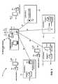
- FIG. 1is a block diagram illustrating the various components of an interactive wireless life safety communications system in accordance with one embodiment of the present disclosure
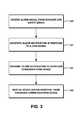
- FIG. 2is a flowchart of one exemplary method for coordinating caregiver response to an alert event
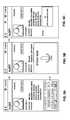
- FIG. 3is a flowchart of another embodiment of the method for coordinating caregiver response to an alert event as performed by a central coordination server;
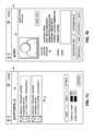
- FIG. 4is a screen capture of a user interface generated on a caregiver communications device, the user interface showing an alert notification;
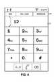
- FIGS. 5A-5Care screen captures of the user interface showing input modalities for providing the action status response
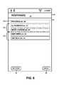
- FIG. 6is a screen capture of the user interface showing a summary of action status responses from other caregiver communications devices
- FIG. 7A-7Dare screen captures of the user interface showing an action status response in which additional assistance from other caregiver staff is being requested;
- FIG. 8is a screen capture of an example user interface for communicating with other caregiver communications devices
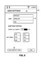
- FIG. 9is a screen capture of the user interface for assigning the caregiver communications device to a specific caregiver staff
- FIG. 10is a screen capture of an example user interface to the central coordination server.
- FIG. 11is an example alert log stored on the central coordination server including received alarm signals, transmitted alert notifications, and received action status responses on the central coordination server.
- Interactive wireless life safety communications systems and methods for coordinating caregiver responsesare contemplated by the present disclosure.
- interactive devicessuch as tablets, smartphones, and the like are provided to facility staff, who can be alerted and provide responsive status updates via the interactive devices.
- the detailed description set forth below in connection with the appended drawingsis intended as a description of certain embodiments of these systems and the methods, and is not intended to represent the only forms that may be developed or utilized.
- the descriptionsets forth the various functions in connection with the illustrated embodiments, but it is to be understood, however, that the same or equivalent functions may be accomplished by different embodiments that are also intended to be encompassed within the scope of the present disclosure. It is further understood that the use of relational terms such as first and second and the like are used solely to distinguish one entity from another without necessarily requiring or implying any actual such relationship or order between such entities.
- assisted livingrefers to a particular level of care that involves the assistance of elderly and disabled residents with certain life activities and health needs. For the most part, it is not as intensive as nursing homes or skilled nursing facilities, though there is more caregiver involvement than independent living. Notwithstanding the exemplary application of the interactive wireless life safety communications system 10 in such an assisted care facility 1 , it is to be understood that such systems and methods of coordinating responses may be applied to any residential facility in which caregiver staff attends to the life and health needs of residents. In this regard, the assisted care facility 1 is referenced by way of example only and not of limitation.
- the assisted care facility 1may be separated into various locations 12 a - 12 d .
- a first location 12 amay be a room belonging to a first resident 14 a .
- a second location 12 bmay be another room belonging to a second resident 14 b
- a third location 12 cmay be still another room belonging to a third resident 14 c .
- a fourth location 12 dmay be another room not necessarily associated with any particular resident.
- the organization of the locations 12 a - 12 dis presented as an illustrative example, and is understood to be particular to the assisted care facility 1 . For instance, if small buildings/cottages are assigned to residents, then each location 12 may be such a unit, rather than a room.
- a given residential unitmay have multiple sub-sections such as a bedroom, a kitchen, a living room, and so forth, and each such sub-section may also be referred to as one of the locations 12 .
- the assisted care facility 1may also include an administrative center 17 , from which various activities of the facility may be managed and coordinated.
- the distance between the administrative center 17 and the different locations 12may vary, though for the sake of convenience and efficiency, is centrally situated.
- the specific arrangement of the administrative center 17depends upon the planning of the assisted care facility 1 .
- the location 12is understood to be related to a physical area within which a resident life safety device 16 may cover to detect various alarm conditions.
- An example first resident life safety device 16 a associated with the first location 12 amay be a motion detector that triggers an alarm signal upon any motion within the area monitored thereby.
- the example second resident 14 bmay be confined to a bed, and hence only a pull cord may be installed as a second resident life safety device 16 b .
- a third resident life safety device 16 cneed not be restricted to a stationary installation to a specific location 12 .
- the fourth location 12 dmay include a fourth resident life safety device 16 d of a smoke detector.
- Other resident life safety devices 16are contemplated, including a door alarm, a window alarm, a fall detector, presence detector, a bed pad, a wander bracelet, and an incontinence detector. Indeed, those having ordinary skill in the art will recognize that any suitable life safety device that detects various environmental conditions, personal conditions (i.e., conditions pertaining to the resident 14 ) and the like may be readily substituted without departing from the scope of the present disclosure.
- Each of the resident life safety devices 16is connected to a central coordination server 18 over a first network 20 .
- the term life safety device 16is understood to encompass any device that communicates with the central coordination server to signal a condition of a resident or a location within the assisted care facility 1 .
- the aforementioned devicessuch as the pull cords, non-wander resident pendants and the like are understood to have alerting functions that are activated by the resident 14 , and do not necessarily have monitoring functions. Some others, such as the bed pads, presence or motion detectors, fall pads, smoke detectors, incontinence pads and wander bracelets that alert approaches to doors and windows have monitoring as well as alert functions.
- Some segments of the first network 20may be a wired connection suitable for linking permanently installed resident life safety devices 16 such as the bed-side pull cord, a door alarm, and the like.
- the segment of the first network 20may be wireless.
- the wireless signals from the resident life safety device 16may be relayed to the central coordination server 18 over a segment of the first network 20 that is wired. It will be recognized that there are different modalities by which the resident life safety devices 16 can be connected to the central coordination server 18 .
- the respective resident life safety device 16Upon detecting an alarm condition, the respective resident life safety device 16 transmits an alarm signal to the central coordination server 18 over the first network 20 . How the alarm condition is detected, and what information is conveyed in the alarm signal, depends on the specifics of the resident life safety device 16 . For example, with a pull cord, the corresponding alarm signal may simply indicate the activation of the resident life safety device 16 and the identity of the resident 14 associated therewith. More sophisticated resident life safety devices 16 may incorporate additional data into the alarm signal to convey additional details of the alarm condition to the central coordination server 18 .
- the central coordination server 18may be a conventional computer system having various input ports for connecting the resident life safety devices 16 .
- the computer systemmay be loaded with executable software instructions that generate certain outputs in response to received inputs, including the aforementioned alarm signals from the resident life safety devices 16 .
- there are many possible topologies of the first network 20including shared medium networks that can interconnect related groups of resident life safety devices 16 that would not require additional routing or switching devices.
- the central coordination server 18is a Windows-based personal computer. Management personnel of the assisted care facility may access a software application that shows real-time operational status updates of the interactive wireless life safety communications system 10 . Such access may be direct, that is, the user interface to the software application is presented on a display device connected to the computer, and it is possible for personnel to navigate various options of the software application using input devices also connected to the computer. Alternatively, it is also possible for the central coordination server 18 to lack a display monitor, keyboard, mouse, and other peripheral devices typical of a personal computer. Instead, management personnel can log in to the central coordination server 18 via a remote terminal that emulates the user interface to the software application. Management of the interactive wireless life safety communications system 10 , vis-à-vis the central coordination server 18 and the software application running thereon, will be discussed in further detail below.
- the assisted care facility 1also employs many caregiver staff 22 , including, for example, a first caregiver staff 22 a , a second staff caregiver 22 b , and the third caregiver staff 22 c , to attend to the needs and emergencies of the residents 14 .
- each of the caregiver staff 22is assigned a communications device 24 .
- These caregiver staff 22may have varying skillsets and specialties such as nursing, emergency medical, custodial, food preparation/delivery, and so forth that are well-suited for assisting the residents 14 .
- a caregiver communications device 24Assigned to each of the caregiver staff 22 is a caregiver communications device 24 .
- the caregiver communications device 24being a tablet computer.
- such tablet computermay include a touch display screen through which its user can interact with a graphical user interface to another software application running thereon.
- the tablet computermay include a conventional short-range data communications modality such as WiFi, via which data communications links to the central coordination server 18 may be established.
- the example caregiver communications device 24is described as a tablet computer, any other suitable multi-function device such as smart phones that are capable of running the same or similar software applications and having wireless networking features may be substituted without departing from the scope of the present disclosure.
- the interactive wireless life safety communications system 10therefore contemplates a second network 26 , which is understood to be different from the first network 20 interconnecting the various resident life safety devices 16 to the central coordination server 18 .
- the second network 26can be deployed in the assisted care facility 1 , including the installation of base stations, antennas, and the like.
- the central coordination server 18 , the caregiver communications device 24 , and other connectivity devicesto accommodate such an alternative network.
- the caregiver communications device 24is envisioned to provide substantially more information to caregiver staff 22 over conventional notification devices utilized in the life safety and assisted care field such as pagers and two-way radios.
- the caregiver communications device 24is receptive to an alarm notification that is generated by the central coordination server 18 in response to a received alarm signal from the resident life safety device 16 .
- caregiver staff 22can provide feedback and updates to administrators via the central coordination server 18 . That is, an action status response may be generated at the command of the caregiver staff 22 for transmission to the central coordination server 18 over the second network 26 .
- the methodbegins with a step 200 of generating the alarm signal.
- the alarm signalis generated by the resident life safety device 16 upon detection of an alarm event. For example, in the case of the smoke detector or fourth resident life safety device 16 d , when a sufficient level of smoke is detected within the fourth location 12 d , then the alarm is triggered, and the alarm signal is generated thereby.
- the content of the alarm signalincludes data that it originates from the resident life safety device 16 d , and may include a descriptor that it represents the smoke detector.
- the fourth location 16 dis not associated with a particular resident 14 , for a resident life safety device 16 that is, the corresponding alarm signal generated may also include an identifier therefor.
- step 202the method continues with transmitting the alarm signal from the resident life safety device 16 to the central coordination server 18 .
- the resident life safety device 16is linked to the central coordination server 18 over the first network 20 .
- Another embodiment of the present disclosurecontemplates a method for the administrative center 17 to coordinate the responses of the caregiver staff 22 .
- the aforementioned step 202 of transmitting the alarm signal to the central coordination server 18has a corollary step 300 of receiving the same alarm signal from the resident life safety device 16 .
- Both methodsinvolve a step 204 , and 302 , respectively, of generating an alarm notification on the central coordination server 18 in response to the received alarm signal. Moreover, both methods also include a step 206 , and 304 , respectively, of transmitting the alarm notification to the caregiver communications devices 24 over the second network 26 .
- the alarm notificationis displayed as a notification screen 29 in a user interface 28 that is generated on the caregiver communications device 24 .
- the alarm notificationincludes a resident identifier 30 , comprised of a resident name 30 a (e.g., John Smith), as well as a graphical representation or photograph 30 b of the resident 14 .
- the photograph of the resident 14is understood to be helpful for new or temporary caregiver staff 22 who may not yet have established a personal relationship with the resident 14 .
- the notification screen 29renders the resident identifier 30 , the location identifier 32 , and the life safety device identifier 34 into appropriate sections thereof, there is also a message section 36 that concisely displays these identifiers.
- Other modalities for visualizing the alarm notifications on the caregiver communications device 24are also contemplated. These include overlaying the alert notifications on a site map of the assisted care facility 1 , in accordance with the location information included therein. For resident life safety devices 16 that can be arbitrarily located within the assisted care facility 1 such as locator pendants worn by the resident 14 , GPS or other coordinate data may be incorporated, and used to display the alert notifications.
- An alert status indicator 38shows that the alert notification is pending. Other statuses such as cleared, when another caregiver staff 22 has responded to the alert notification, may also be shown as the alert status indicator 38 .
- the caregiver communications device 24Upon receipt of the alert notification, in addition to showing the alert status indicator, the caregiver communications device 24 generates an audible alert, as well as a vibration output.
- the caregiver communications device 24is contemplated to be interactive, in that the caregiver staff 22 provides inputs that, in turn, generate responses that are passed to the central coordination server 18 . These responses are also referred to as an action status response.
- the method for coordinating caregiver responsescontinues with a step 208 of receiving caregiver input that corresponds to the action status response.
- the notification screen 29includes a responding action status button 40 , as well as a declining action status button 42 . It is understood that the caregiver staff 22 presses the responding action status button 40 when, upon viewing the alert notification, is willing and able to respond to it.
- the caregiver staff 22By activating the responding action status button 40 , the caregiver staff 22 is communicating to the administrative center 17 as well as to other caregiver staff 22 that he or she is responding. Otherwise, the caregiver staff 22 presses the declining action status button 42 , effectively indicating to other staff that he or she is not available.
- the caregiver staff 22When responding, it is possible for the caregiver staff 22 to include additional information in a text input box 44 .
- a virtual keyboard 46may be overlaid on the user interface 28 to accept text input.
- a microphone on the caregiver communications device 24may be activated to receive dictation from the caregiver staff 22 .
- An icon 48 representative of the capacity to accept sound inputis displayed.
- the software applicationmay process the received audio data and convert the same to text data in accordance with one of many known voice recognition algorithms and software implementations thereof.
- the received informationis rendered within the text input box 44 , as best illustrated in FIG. 5C .
- the information entered into the text input box 44may be saved after activating a save button 45 .
- pictures, videos, and other multimedia contentmay be recorded on the caregiver communications device 24 that can be appended to the action status response.
- activating the responding action status button 40 or the declining action status button 42is operative to transmit the action status response to the central coordination server 18 .
- Thisis understood to be a step 210 in the method for coordinating caregiver staff 22 responses to the alarm events.
- the action status responseis transmitted over the second network 26 .
- Such updatesmay be further propagated to the other caregiver communications devices 24 connected to the central coordination server 18 .
- the caregiver communications devices 24are in constant communication with the central coordination server 18 .
- the notification screen 29is updated automatically.
- a refresh button 46may be pressed, which is operative to poll the central coordination server 18 .
- the notification screen 29further includes another button 48 , which invokes a response details screen 50 that is displayed in the user interface 28 .
- Each of the caregiver staff 22are listed therein, along with an identifier of the caregiver communications device 24 .
- Highlighted in a first colore.g., green
- a second colore.g., yellow
- those caregiver staff 52 c who declined the alert notificationare highlighted in a third color (e.g., red).
- the listing in the response details interface 50may be constantly refreshed, while in others, only periodic download of the data from the central coordination server 18 may occur. For the latter, there is provided a refresh button 54 that, when selected, polls the central coordination server 18 for the most updated response information. The selection of a back button 56 returns the user interface 28 to the notification screen 29 .
- a button 58can be invoked.
- the resident life safety device 16is a wearable pendant that can act as a distress signaler.
- an alert detail screen 60is generated in the user interface 28 .
- an alert hold section 62 and an alert clear section 64may be provided. These are understood to add further levels of refinement to the action status response of holding the alert and clearing the alert, respectively.
- FIG. 7Cillustrates an example alert activity screen 68 presented to the non-originating caregiver staff 22 .
- This screenmay include a listing 70 of other active alerts, and its entries are understood to be interactive as well. That is, selecting an entry 70 a may invoke another notification screen 29 as shown in FIG. 7D that corresponds to the request for assistance, and in the message section 36 , is indicated thus.
- the central coordination server 18can update the alarm notification and have the cleared status reflected amongst the caregiver communications devices 24 .
- the caregiver communication devices 24can utilize a voice public branch exchange (PBX) network 23 to initiate telephone calls over telephone service 27 .
- PBXpublic branch exchange
- the central coordination server 18includes a telephone line card 25 connected to the PBX 23 and to the telephone service 27 .
- the caregiver staff 22may place 911 emergency calls and otherwise contact off-site personnel. Furthermore, it is possible to place calls to residents 14 at their listed telephone numbers from the caregiver communications device 24 .
- the caregiver communications devices 24are assigned to each individual caregiver staff 22 .
- the caregiver communications devices 24are stored and its batteries are being charged at the administrative center 17 .
- the caregiver staff 22check in with the administrative center 17 prior to each shift, and randomly picks up one of the caregiver communications devices 24 .
- the user interface 28generates a device assignment screen 74 .
- a save button 80can be actuated to record the identity with the central coordination server 18 .
- the caregiver communications device 24are assigned to a specific caregiver staff, other administrative functions can be performed therewith. For example, staff-wide broadcast announcements can be transmitted from the central coordination server 18 . Furthermore, staff check-ins while making rounds, staff timekeeping for logging working hours, etc. can also be processed and recorded. Being an interactive device with two-way communications capabilities, the caregiver communications device 24 can be used to submit maintenance requests, schedule housekeeping services, submit meal requests, and so forth directly on site. As such, the assisted care facility 1 can be much more responsive to the residents' needs.
- Another caregiver communications device 24may be used to access the central coordination server 18 to retrieve ongoing activity within the interactive wireless life safety communications system 10 .
- the datais rendered in the user interface 28 as a supervisory screen 82 , which includes a listing 84 of the most recent alert notifications issued by the central coordination server 18 .
- the alert notifications to which the caregiver staff 22 responded 84 aare shown highlighted in one color (e.g., green) while currently active alert notifications 84 b are shown highlighted in a different color (e.g., red).
- a refresh buttonwhich of the listings are shown in the supervisory screen 82 are selected via switches 88 , including a first switch 88 a for showing all alert notifications or not, and a second switch 88 b for showing cleared alert notifications or not.
- the time limit for showing all alert notificationsmay be limited to the last 24 hours, or any other arbitrary duration.
- the central coordination server 18is contemplated to generate and store various reports that may be categorized according to the specific resident 14 , specific resident life safety devices 16 across the entire deployment in the assisted care facility 1 , a specific resident life safety device 16 for a specific resident 14 , and any other useful categorization that provides a meaningful view of the residents 14 , the assisted care facility 1 , and the caregiver staff 22 .
- One exemplary reportis illustrated in FIG. 11 , which is a listing of alert notifications and responses generated for a specific resident 14 , i.e., “John Smith.”
Landscapes
- Business, Economics & Management (AREA)
- Emergency Management (AREA)
- Physics & Mathematics (AREA)
- General Physics & Mathematics (AREA)
- Engineering & Computer Science (AREA)
- Health & Medical Sciences (AREA)
- General Health & Medical Sciences (AREA)
- Gerontology & Geriatric Medicine (AREA)
- Computer Security & Cryptography (AREA)
- Computer Networks & Wireless Communication (AREA)
- Alarm Systems (AREA)
Abstract
Description
Claims (20)
Priority Applications (2)
| Application Number | Priority Date | Filing Date | Title |
|---|---|---|---|
| US16/386,046US10380873B1 (en) | 2012-09-12 | 2019-04-16 | Interactive wireless life safety communications system |
| US16/504,647US11328578B2 (en) | 2012-09-12 | 2019-07-08 | Interactive wireless life safety communications system |
Applications Claiming Priority (5)
| Application Number | Priority Date | Filing Date | Title |
|---|---|---|---|
| US13/611,426US20140070939A1 (en) | 2012-09-12 | 2012-09-12 | Interactive wireless life safety communications system |
| US14/468,837US9305450B2 (en) | 2012-09-12 | 2014-08-26 | Interactive wireless life safety communications system |
| US15/058,002US20160180681A1 (en) | 2012-09-12 | 2016-03-01 | Interactive wireless life safety communications system |
| US15/299,080US10311707B2 (en) | 2012-09-12 | 2016-10-20 | Interactive wireless life safety communications system |
| US16/386,046US10380873B1 (en) | 2012-09-12 | 2019-04-16 | Interactive wireless life safety communications system |
Related Parent Applications (2)
| Application Number | Title | Priority Date | Filing Date |
|---|---|---|---|
| US13/611,426ContinuationUS20140070939A1 (en) | 2012-09-12 | 2012-09-12 | Interactive wireless life safety communications system |
| US15/299,080ContinuationUS10311707B2 (en) | 2012-09-12 | 2016-10-20 | Interactive wireless life safety communications system |
Related Child Applications (1)
| Application Number | Title | Priority Date | Filing Date |
|---|---|---|---|
| US16/504,647ContinuationUS11328578B2 (en) | 2012-09-12 | 2019-07-08 | Interactive wireless life safety communications system |
Publications (2)
| Publication Number | Publication Date |
|---|---|
| US20190244512A1 US20190244512A1 (en) | 2019-08-08 |
| US10380873B1true US10380873B1 (en) | 2019-08-13 |
Family
ID=50232702
Family Applications (6)
| Application Number | Title | Priority Date | Filing Date |
|---|---|---|---|
| US13/611,426AbandonedUS20140070939A1 (en) | 2012-09-12 | 2012-09-12 | Interactive wireless life safety communications system |
| US14/468,837ActiveUS9305450B2 (en) | 2012-09-12 | 2014-08-26 | Interactive wireless life safety communications system |
| US15/058,002AbandonedUS20160180681A1 (en) | 2012-09-12 | 2016-03-01 | Interactive wireless life safety communications system |
| US15/299,080ActiveUS10311707B2 (en) | 2012-09-12 | 2016-10-20 | Interactive wireless life safety communications system |
| US16/386,046ActiveUS10380873B1 (en) | 2012-09-12 | 2019-04-16 | Interactive wireless life safety communications system |
| US16/504,647ActiveUS11328578B2 (en) | 2012-09-12 | 2019-07-08 | Interactive wireless life safety communications system |
Family Applications Before (4)
| Application Number | Title | Priority Date | Filing Date |
|---|---|---|---|
| US13/611,426AbandonedUS20140070939A1 (en) | 2012-09-12 | 2012-09-12 | Interactive wireless life safety communications system |
| US14/468,837ActiveUS9305450B2 (en) | 2012-09-12 | 2014-08-26 | Interactive wireless life safety communications system |
| US15/058,002AbandonedUS20160180681A1 (en) | 2012-09-12 | 2016-03-01 | Interactive wireless life safety communications system |
| US15/299,080ActiveUS10311707B2 (en) | 2012-09-12 | 2016-10-20 | Interactive wireless life safety communications system |
Family Applications After (1)
| Application Number | Title | Priority Date | Filing Date |
|---|---|---|---|
| US16/504,647ActiveUS11328578B2 (en) | 2012-09-12 | 2019-07-08 | Interactive wireless life safety communications system |
Country Status (1)
| Country | Link |
|---|---|
| US (6) | US20140070939A1 (en) |
Cited By (72)
| Publication number | Priority date | Publication date | Assignee | Title |
|---|---|---|---|---|
| US10523689B2 (en) | 2007-06-12 | 2019-12-31 | Icontrol Networks, Inc. | Communication protocols over internet protocol (IP) networks |
| US10616075B2 (en) | 2007-06-12 | 2020-04-07 | Icontrol Networks, Inc. | Communication protocols in integrated systems |
| US10616244B2 (en) | 2006-06-12 | 2020-04-07 | Icontrol Networks, Inc. | Activation of gateway device |
| US10657794B1 (en) | 2007-02-28 | 2020-05-19 | Icontrol Networks, Inc. | Security, monitoring and automation controller access and use of legacy security control panel information |
| US10666523B2 (en) | 2007-06-12 | 2020-05-26 | Icontrol Networks, Inc. | Communication protocols in integrated systems |
| US10672254B2 (en) | 2007-04-23 | 2020-06-02 | Icontrol Networks, Inc. | Method and system for providing alternate network access |
| US10691295B2 (en) | 2004-03-16 | 2020-06-23 | Icontrol Networks, Inc. | User interface in a premises network |
| US10692356B2 (en) | 2004-03-16 | 2020-06-23 | Icontrol Networks, Inc. | Control system user interface |
| US10721087B2 (en) | 2005-03-16 | 2020-07-21 | Icontrol Networks, Inc. | Method for networked touchscreen with integrated interfaces |
| US10735249B2 (en) | 2004-03-16 | 2020-08-04 | Icontrol Networks, Inc. | Management of a security system at a premises |
| US10741057B2 (en) | 2010-12-17 | 2020-08-11 | Icontrol Networks, Inc. | Method and system for processing security event data |
| US10747216B2 (en) | 2007-02-28 | 2020-08-18 | Icontrol Networks, Inc. | Method and system for communicating with and controlling an alarm system from a remote server |
| US10754304B2 (en) | 2004-03-16 | 2020-08-25 | Icontrol Networks, Inc. | Automation system with mobile interface |
| US10785319B2 (en) | 2006-06-12 | 2020-09-22 | Icontrol Networks, Inc. | IP device discovery systems and methods |
| US10796557B2 (en) | 2004-03-16 | 2020-10-06 | Icontrol Networks, Inc. | Automation system user interface with three-dimensional display |
| US10930136B2 (en) | 2005-03-16 | 2021-02-23 | Icontrol Networks, Inc. | Premise management systems and methods |
| US10979389B2 (en) | 2004-03-16 | 2021-04-13 | Icontrol Networks, Inc. | Premises management configuration and control |
| US10992784B2 (en) | 2004-03-16 | 2021-04-27 | Control Networks, Inc. | Communication protocols over internet protocol (IP) networks |
| US10999254B2 (en) | 2005-03-16 | 2021-05-04 | Icontrol Networks, Inc. | System for data routing in networks |
| US11043112B2 (en) | 2004-03-16 | 2021-06-22 | Icontrol Networks, Inc. | Integrated security system with parallel processing architecture |
| US11089122B2 (en) | 2007-06-12 | 2021-08-10 | Icontrol Networks, Inc. | Controlling data routing among networks |
| US11113950B2 (en) | 2005-03-16 | 2021-09-07 | Icontrol Networks, Inc. | Gateway integrated with premises security system |
| US11146637B2 (en) | 2014-03-03 | 2021-10-12 | Icontrol Networks, Inc. | Media content management |
| US11153266B2 (en) | 2004-03-16 | 2021-10-19 | Icontrol Networks, Inc. | Gateway registry methods and systems |
| US11182060B2 (en) | 2004-03-16 | 2021-11-23 | Icontrol Networks, Inc. | Networked touchscreen with integrated interfaces |
| US11184322B2 (en) | 2004-03-16 | 2021-11-23 | Icontrol Networks, Inc. | Communication protocols in integrated systems |
| US11190578B2 (en) | 2008-08-11 | 2021-11-30 | Icontrol Networks, Inc. | Integrated cloud system with lightweight gateway for premises automation |
| US11201755B2 (en) | 2004-03-16 | 2021-12-14 | Icontrol Networks, Inc. | Premises system management using status signal |
| US11212192B2 (en) | 2007-06-12 | 2021-12-28 | Icontrol Networks, Inc. | Communication protocols in integrated systems |
| US11218878B2 (en) | 2007-06-12 | 2022-01-04 | Icontrol Networks, Inc. | Communication protocols in integrated systems |
| US11240059B2 (en) | 2010-12-20 | 2022-02-01 | Icontrol Networks, Inc. | Defining and implementing sensor triggered response rules |
| US11237714B2 (en) | 2007-06-12 | 2022-02-01 | Control Networks, Inc. | Control system user interface |
| US11244545B2 (en) | 2004-03-16 | 2022-02-08 | Icontrol Networks, Inc. | Cross-client sensor user interface in an integrated security network |
| US11258625B2 (en) | 2008-08-11 | 2022-02-22 | Icontrol Networks, Inc. | Mobile premises automation platform |
| US11277465B2 (en) | 2004-03-16 | 2022-03-15 | Icontrol Networks, Inc. | Generating risk profile using data of home monitoring and security system |
| US11296950B2 (en) | 2013-06-27 | 2022-04-05 | Icontrol Networks, Inc. | Control system user interface |
| US11310199B2 (en) | 2004-03-16 | 2022-04-19 | Icontrol Networks, Inc. | Premises management configuration and control |
| US11316958B2 (en) | 2008-08-11 | 2022-04-26 | Icontrol Networks, Inc. | Virtual device systems and methods |
| US11316753B2 (en) | 2007-06-12 | 2022-04-26 | Icontrol Networks, Inc. | Communication protocols in integrated systems |
| US11343380B2 (en) | 2004-03-16 | 2022-05-24 | Icontrol Networks, Inc. | Premises system automation |
| US11368327B2 (en) | 2008-08-11 | 2022-06-21 | Icontrol Networks, Inc. | Integrated cloud system for premises automation |
| US11398147B2 (en) | 2010-09-28 | 2022-07-26 | Icontrol Networks, Inc. | Method, system and apparatus for automated reporting of account and sensor zone information to a central station |
| US11405463B2 (en) | 2014-03-03 | 2022-08-02 | Icontrol Networks, Inc. | Media content management |
| US11412027B2 (en) | 2007-01-24 | 2022-08-09 | Icontrol Networks, Inc. | Methods and systems for data communication |
| US11423756B2 (en) | 2007-06-12 | 2022-08-23 | Icontrol Networks, Inc. | Communication protocols in integrated systems |
| US11424980B2 (en) | 2005-03-16 | 2022-08-23 | Icontrol Networks, Inc. | Forming a security network including integrated security system components |
| US11451409B2 (en) | 2005-03-16 | 2022-09-20 | Icontrol Networks, Inc. | Security network integrating security system and network devices |
| US11489812B2 (en) | 2004-03-16 | 2022-11-01 | Icontrol Networks, Inc. | Forming a security network including integrated security system components and network devices |
| US11496568B2 (en) | 2005-03-16 | 2022-11-08 | Icontrol Networks, Inc. | Security system with networked touchscreen |
| US11582065B2 (en) | 2007-06-12 | 2023-02-14 | Icontrol Networks, Inc. | Systems and methods for device communication |
| US11601810B2 (en) | 2007-06-12 | 2023-03-07 | Icontrol Networks, Inc. | Communication protocols in integrated systems |
| US11615697B2 (en) | 2005-03-16 | 2023-03-28 | Icontrol Networks, Inc. | Premise management systems and methods |
| US11646907B2 (en) | 2007-06-12 | 2023-05-09 | Icontrol Networks, Inc. | Communication protocols in integrated systems |
| US11677577B2 (en) | 2004-03-16 | 2023-06-13 | Icontrol Networks, Inc. | Premises system management using status signal |
| US11700142B2 (en) | 2005-03-16 | 2023-07-11 | Icontrol Networks, Inc. | Security network integrating security system and network devices |
| US11706045B2 (en) | 2005-03-16 | 2023-07-18 | Icontrol Networks, Inc. | Modular electronic display platform |
| US11706279B2 (en) | 2007-01-24 | 2023-07-18 | Icontrol Networks, Inc. | Methods and systems for data communication |
| US11729255B2 (en) | 2008-08-11 | 2023-08-15 | Icontrol Networks, Inc. | Integrated cloud system with lightweight gateway for premises automation |
| US11750414B2 (en) | 2010-12-16 | 2023-09-05 | Icontrol Networks, Inc. | Bidirectional security sensor communication for a premises security system |
| US11758026B2 (en) | 2008-08-11 | 2023-09-12 | Icontrol Networks, Inc. | Virtual device systems and methods |
| US11792036B2 (en) | 2008-08-11 | 2023-10-17 | Icontrol Networks, Inc. | Mobile premises automation platform |
| US11792330B2 (en) | 2005-03-16 | 2023-10-17 | Icontrol Networks, Inc. | Communication and automation in a premises management system |
| US11811845B2 (en) | 2004-03-16 | 2023-11-07 | Icontrol Networks, Inc. | Communication protocols over internet protocol (IP) networks |
| US11816323B2 (en) | 2008-06-25 | 2023-11-14 | Icontrol Networks, Inc. | Automation system user interface |
| US11831462B2 (en) | 2007-08-24 | 2023-11-28 | Icontrol Networks, Inc. | Controlling data routing in premises management systems |
| US11916870B2 (en) | 2004-03-16 | 2024-02-27 | Icontrol Networks, Inc. | Gateway registry methods and systems |
| US11916928B2 (en) | 2008-01-24 | 2024-02-27 | Icontrol Networks, Inc. | Communication protocols over internet protocol (IP) networks |
| US12003387B2 (en) | 2012-06-27 | 2024-06-04 | Comcast Cable Communications, Llc | Control system user interface |
| US12063221B2 (en) | 2006-06-12 | 2024-08-13 | Icontrol Networks, Inc. | Activation of gateway device |
| US12063220B2 (en) | 2004-03-16 | 2024-08-13 | Icontrol Networks, Inc. | Communication protocols in integrated systems |
| US12184443B2 (en) | 2007-06-12 | 2024-12-31 | Icontrol Networks, Inc. | Controlling data routing among networks |
| US12283172B2 (en) | 2007-06-12 | 2025-04-22 | Icontrol Networks, Inc. | Communication protocols in integrated systems |
Families Citing this family (23)
| Publication number | Priority date | Publication date | Assignee | Title |
|---|---|---|---|---|
| US9280637B2 (en)* | 2012-10-05 | 2016-03-08 | Cerner Innovation, Inc. | Multi-action button for mobile devices |
| US10275570B2 (en) | 2012-12-31 | 2019-04-30 | Cerner Innovation, Inc. | Closed loop alert management |
| US9185202B2 (en) | 2012-12-31 | 2015-11-10 | Cerner Innovation, Inc. | Alert management utilizing mobile devices |
| US20140327519A1 (en)* | 2013-05-03 | 2014-11-06 | Nick Carroll | Interactive safety system |
| AU2015236500A1 (en)* | 2014-03-18 | 2016-11-03 | Ristcall Llc | Wireless patient care system and method |
| US10068460B2 (en) | 2015-06-04 | 2018-09-04 | ESCO Technologies, LLC | Interactive media device |
| US10249174B2 (en) | 2015-07-31 | 2019-04-02 | Siemens Industry, Inc. | Wireless emergency alert notifications |
| US10607728B2 (en) | 2015-10-06 | 2020-03-31 | Cerner Innovation, Inc. | Alert optimizer |
| US10037411B2 (en) | 2015-12-30 | 2018-07-31 | Cerner Innovation, Inc. | Intelligent alert suppression |
| US20170345419A1 (en)* | 2016-05-31 | 2017-11-30 | Essence Smartcare Ltd. | System and method for a reduced power alarm system |
| US10258295B2 (en)* | 2017-05-09 | 2019-04-16 | LifePod Solutions, Inc. | Voice controlled assistance for monitoring adverse events of a user and/or coordinating emergency actions such as caregiver communication |
| US11138861B2 (en)* | 2017-05-25 | 2021-10-05 | Robert Blatt | Easily customizable inhabitant behavioral routines in a location monitoring and action system |
| US10957445B2 (en) | 2017-10-05 | 2021-03-23 | Hill-Rom Services, Inc. | Caregiver and staff information system |
| US10679748B2 (en) | 2017-12-22 | 2020-06-09 | Stryker Corporation | Techniques for remotely controlling a medical device based on image data |
| US11123246B2 (en) | 2017-12-22 | 2021-09-21 | Stryker Corporation | Techniques for managing patient therapy protocols |
| US10905611B2 (en) | 2017-12-22 | 2021-02-02 | Stryker Corporation | Techniques for notifying persons within a vicinity of a patient support apparatus of a remote control function |
| KR20200093622A (en)* | 2018-01-25 | 2020-08-05 | 비트, 인크. | Process digitization system and method |
| GB2601071B (en) | 2018-06-29 | 2022-12-28 | Halo Smart Solutions Inc | Sensor device and system |
| US10939273B1 (en)* | 2020-04-14 | 2021-03-02 | Soter Technologies, Llc | Systems and methods for notifying particular devices based on estimated distance |
| US11259167B2 (en) | 2020-04-14 | 2022-02-22 | Soter Technologies, Llc | Systems and methods for notifying particular devices based on estimated distance |
| US11410655B1 (en) | 2021-07-26 | 2022-08-09 | LifePod Solutions, Inc. | Systems and methods for managing voice environments and voice routines |
| US11404062B1 (en) | 2021-07-26 | 2022-08-02 | LifePod Solutions, Inc. | Systems and methods for managing voice environments and voice routines |
| US11302174B1 (en) | 2021-09-22 | 2022-04-12 | Halo Smart Solutions, Inc. | Heat-not-burn activity detection device, system and method |
Citations (10)
| Publication number | Priority date | Publication date | Assignee | Title |
|---|---|---|---|---|
| US5534851A (en)* | 1991-03-06 | 1996-07-09 | Russek; Linda G. | Alarm for patient monitor and life support equipment |
| US20050151640A1 (en)* | 2003-12-31 | 2005-07-14 | Ge Medical Systems Information Technologies, Inc. | Notification alarm transfer methods, system, and device |
| US20070073555A1 (en)* | 2003-10-29 | 2007-03-29 | Patientrack Pty Ltd. | System and process for facilitating the provision of health care |
| US20080004904A1 (en)* | 2006-06-30 | 2008-01-03 | Tran Bao Q | Systems and methods for providing interoperability among healthcare devices |
| US20090206992A1 (en)* | 2008-02-14 | 2009-08-20 | Proxense, Llc | Proximity-Based Healthcare Management System With Automatic Access To Private Information |
| US20090326340A1 (en)* | 2008-06-30 | 2009-12-31 | Hui Wang | Patient Monitor Alarm System And Method |
| US20110199214A1 (en)* | 2010-02-18 | 2011-08-18 | Ute Gawlick | Medical personnel alert rules based on grouping |
| US20110255670A1 (en)* | 2007-01-22 | 2011-10-20 | Seidberg Daniel R | Emergency responder reply system and related methods |
| US8098153B2 (en)* | 2003-07-22 | 2012-01-17 | Kraus Mark W | System and method of providing emergency response to a user carrying a user device |
| US20120169467A1 (en)* | 2010-12-31 | 2012-07-05 | Condra David L | Patient alert management system |
Family Cites Families (12)
| Publication number | Priority date | Publication date | Assignee | Title |
|---|---|---|---|---|
| US5262944A (en)* | 1992-05-15 | 1993-11-16 | Hewlett-Packard Company | Method for use of color and selective highlighting to indicate patient critical events in a centralized patient monitoring system |
| US7606720B1 (en) | 1999-12-22 | 2009-10-20 | Ge Medical Systems, Inc. | Medical facility communications topology |
| ES2362414T3 (en) | 2000-05-19 | 2011-07-05 | Welch Allyn Protocol Inc | PATIENT MONITORING SYSTEM. |
| US7026926B1 (en) | 2002-08-15 | 2006-04-11 | Walker Iii Ethan A | System and method for wireless transmission of security alarms to selected groups |
| US20050283382A1 (en)* | 2004-06-21 | 2005-12-22 | Epic Systems Corporation | System and method for managing and tracking the location of patients and health care facility resources in a health care facility |
| US7348883B2 (en) | 2004-08-16 | 2008-03-25 | Sloan Dale A | Medical communication and locator system and method |
| US8002701B2 (en) | 2006-03-10 | 2011-08-23 | Angel Medical Systems, Inc. | Medical alarm and communication system and methods |
| US8183987B2 (en)* | 2006-07-17 | 2012-05-22 | Patient Provider Communications, Inc. | Method and system for advanced patient communication |
| US9361769B2 (en) | 2006-07-17 | 2016-06-07 | Eloquence Communications, Inc. | Method and system for advanced patient communication |
| US20110093296A1 (en)* | 2009-10-18 | 2011-04-21 | James Edward Klink | Medical Identification Wristband |
| US8965327B2 (en)* | 2011-06-09 | 2015-02-24 | Alan H. Davis | Interactive multi-channel communication system |
| CA2782272C (en)* | 2012-07-06 | 2013-09-03 | CellTrak Technologies, Inc. | Systems and methods for a destination-based care services model |
- 2012
- 2012-09-12USUS13/611,426patent/US20140070939A1/ennot_activeAbandoned
- 2014
- 2014-08-26USUS14/468,837patent/US9305450B2/enactiveActive
- 2016
- 2016-03-01USUS15/058,002patent/US20160180681A1/ennot_activeAbandoned
- 2016-10-20USUS15/299,080patent/US10311707B2/enactiveActive
- 2019
- 2019-04-16USUS16/386,046patent/US10380873B1/enactiveActive
- 2019-07-08USUS16/504,647patent/US11328578B2/enactiveActive
Patent Citations (10)
| Publication number | Priority date | Publication date | Assignee | Title |
|---|---|---|---|---|
| US5534851A (en)* | 1991-03-06 | 1996-07-09 | Russek; Linda G. | Alarm for patient monitor and life support equipment |
| US8098153B2 (en)* | 2003-07-22 | 2012-01-17 | Kraus Mark W | System and method of providing emergency response to a user carrying a user device |
| US20070073555A1 (en)* | 2003-10-29 | 2007-03-29 | Patientrack Pty Ltd. | System and process for facilitating the provision of health care |
| US20050151640A1 (en)* | 2003-12-31 | 2005-07-14 | Ge Medical Systems Information Technologies, Inc. | Notification alarm transfer methods, system, and device |
| US20080004904A1 (en)* | 2006-06-30 | 2008-01-03 | Tran Bao Q | Systems and methods for providing interoperability among healthcare devices |
| US20110255670A1 (en)* | 2007-01-22 | 2011-10-20 | Seidberg Daniel R | Emergency responder reply system and related methods |
| US20090206992A1 (en)* | 2008-02-14 | 2009-08-20 | Proxense, Llc | Proximity-Based Healthcare Management System With Automatic Access To Private Information |
| US20090326340A1 (en)* | 2008-06-30 | 2009-12-31 | Hui Wang | Patient Monitor Alarm System And Method |
| US20110199214A1 (en)* | 2010-02-18 | 2011-08-18 | Ute Gawlick | Medical personnel alert rules based on grouping |
| US20120169467A1 (en)* | 2010-12-31 | 2012-07-05 | Condra David L | Patient alert management system |
Cited By (139)
| Publication number | Priority date | Publication date | Assignee | Title |
|---|---|---|---|---|
| US11244545B2 (en) | 2004-03-16 | 2022-02-08 | Icontrol Networks, Inc. | Cross-client sensor user interface in an integrated security network |
| US12253833B2 (en) | 2004-03-16 | 2025-03-18 | Icontrol Networks, Inc. | Automation system with mobile interface |
| US12063220B2 (en) | 2004-03-16 | 2024-08-13 | Icontrol Networks, Inc. | Communication protocols in integrated systems |
| US11991306B2 (en) | 2004-03-16 | 2024-05-21 | Icontrol Networks, Inc. | Premises system automation |
| US11916870B2 (en) | 2004-03-16 | 2024-02-27 | Icontrol Networks, Inc. | Gateway registry methods and systems |
| US11893874B2 (en) | 2004-03-16 | 2024-02-06 | Icontrol Networks, Inc. | Networked touchscreen with integrated interfaces |
| US11811845B2 (en) | 2004-03-16 | 2023-11-07 | Icontrol Networks, Inc. | Communication protocols over internet protocol (IP) networks |
| US10691295B2 (en) | 2004-03-16 | 2020-06-23 | Icontrol Networks, Inc. | User interface in a premises network |
| US10692356B2 (en) | 2004-03-16 | 2020-06-23 | Icontrol Networks, Inc. | Control system user interface |
| US11810445B2 (en) | 2004-03-16 | 2023-11-07 | Icontrol Networks, Inc. | Cross-client sensor user interface in an integrated security network |
| US10735249B2 (en) | 2004-03-16 | 2020-08-04 | Icontrol Networks, Inc. | Management of a security system at a premises |
| US11782394B2 (en) | 2004-03-16 | 2023-10-10 | Icontrol Networks, Inc. | Automation system with mobile interface |
| US11757834B2 (en) | 2004-03-16 | 2023-09-12 | Icontrol Networks, Inc. | Communication protocols in integrated systems |
| US10754304B2 (en) | 2004-03-16 | 2020-08-25 | Icontrol Networks, Inc. | Automation system with mobile interface |
| US11677577B2 (en) | 2004-03-16 | 2023-06-13 | Icontrol Networks, Inc. | Premises system management using status signal |
| US10796557B2 (en) | 2004-03-16 | 2020-10-06 | Icontrol Networks, Inc. | Automation system user interface with three-dimensional display |
| US11656667B2 (en) | 2004-03-16 | 2023-05-23 | Icontrol Networks, Inc. | Integrated security system with parallel processing architecture |
| US10890881B2 (en) | 2004-03-16 | 2021-01-12 | Icontrol Networks, Inc. | Premises management networking |
| US11626006B2 (en) | 2004-03-16 | 2023-04-11 | Icontrol Networks, Inc. | Management of a security system at a premises |
| US10979389B2 (en) | 2004-03-16 | 2021-04-13 | Icontrol Networks, Inc. | Premises management configuration and control |
| US10992784B2 (en) | 2004-03-16 | 2021-04-27 | Control Networks, Inc. | Communication protocols over internet protocol (IP) networks |
| US11625008B2 (en) | 2004-03-16 | 2023-04-11 | Icontrol Networks, Inc. | Premises management networking |
| US11043112B2 (en) | 2004-03-16 | 2021-06-22 | Icontrol Networks, Inc. | Integrated security system with parallel processing architecture |
| US11082395B2 (en) | 2004-03-16 | 2021-08-03 | Icontrol Networks, Inc. | Premises management configuration and control |
| US11601397B2 (en) | 2004-03-16 | 2023-03-07 | Icontrol Networks, Inc. | Premises management configuration and control |
| US11588787B2 (en) | 2004-03-16 | 2023-02-21 | Icontrol Networks, Inc. | Premises management configuration and control |
| US11537186B2 (en) | 2004-03-16 | 2022-12-27 | Icontrol Networks, Inc. | Integrated security system with parallel processing architecture |
| US11489812B2 (en) | 2004-03-16 | 2022-11-01 | Icontrol Networks, Inc. | Forming a security network including integrated security system components and network devices |
| US11449012B2 (en) | 2004-03-16 | 2022-09-20 | Icontrol Networks, Inc. | Premises management networking |
| US11153266B2 (en) | 2004-03-16 | 2021-10-19 | Icontrol Networks, Inc. | Gateway registry methods and systems |
| US11159484B2 (en) | 2004-03-16 | 2021-10-26 | Icontrol Networks, Inc. | Forming a security network including integrated security system components and network devices |
| US11175793B2 (en) | 2004-03-16 | 2021-11-16 | Icontrol Networks, Inc. | User interface in a premises network |
| US11182060B2 (en) | 2004-03-16 | 2021-11-23 | Icontrol Networks, Inc. | Networked touchscreen with integrated interfaces |
| US11184322B2 (en) | 2004-03-16 | 2021-11-23 | Icontrol Networks, Inc. | Communication protocols in integrated systems |
| US11410531B2 (en) | 2004-03-16 | 2022-08-09 | Icontrol Networks, Inc. | Automation system user interface with three-dimensional display |
| US11378922B2 (en) | 2004-03-16 | 2022-07-05 | Icontrol Networks, Inc. | Automation system with mobile interface |
| US11201755B2 (en) | 2004-03-16 | 2021-12-14 | Icontrol Networks, Inc. | Premises system management using status signal |
| US11368429B2 (en) | 2004-03-16 | 2022-06-21 | Icontrol Networks, Inc. | Premises management configuration and control |
| US11343380B2 (en) | 2004-03-16 | 2022-05-24 | Icontrol Networks, Inc. | Premises system automation |
| US11310199B2 (en) | 2004-03-16 | 2022-04-19 | Icontrol Networks, Inc. | Premises management configuration and control |
| US11277465B2 (en) | 2004-03-16 | 2022-03-15 | Icontrol Networks, Inc. | Generating risk profile using data of home monitoring and security system |
| US11792330B2 (en) | 2005-03-16 | 2023-10-17 | Icontrol Networks, Inc. | Communication and automation in a premises management system |
| US11706045B2 (en) | 2005-03-16 | 2023-07-18 | Icontrol Networks, Inc. | Modular electronic display platform |
| US12277853B2 (en) | 2005-03-16 | 2025-04-15 | Icontrol Networks, Inc. | Gateway integrated with premises security system |
| US11113950B2 (en) | 2005-03-16 | 2021-09-07 | Icontrol Networks, Inc. | Gateway integrated with premises security system |
| US11451409B2 (en) | 2005-03-16 | 2022-09-20 | Icontrol Networks, Inc. | Security network integrating security system and network devices |
| US11595364B2 (en) | 2005-03-16 | 2023-02-28 | Icontrol Networks, Inc. | System for data routing in networks |
| US11424980B2 (en) | 2005-03-16 | 2022-08-23 | Icontrol Networks, Inc. | Forming a security network including integrated security system components |
| US11824675B2 (en) | 2005-03-16 | 2023-11-21 | Icontrol Networks, Inc. | Networked touchscreen with integrated interfaces |
| US11615697B2 (en) | 2005-03-16 | 2023-03-28 | Icontrol Networks, Inc. | Premise management systems and methods |
| US10721087B2 (en) | 2005-03-16 | 2020-07-21 | Icontrol Networks, Inc. | Method for networked touchscreen with integrated interfaces |
| US10999254B2 (en) | 2005-03-16 | 2021-05-04 | Icontrol Networks, Inc. | System for data routing in networks |
| US10930136B2 (en) | 2005-03-16 | 2021-02-23 | Icontrol Networks, Inc. | Premise management systems and methods |
| US11367340B2 (en) | 2005-03-16 | 2022-06-21 | Icontrol Networks, Inc. | Premise management systems and methods |
| US11496568B2 (en) | 2005-03-16 | 2022-11-08 | Icontrol Networks, Inc. | Security system with networked touchscreen |
| US11700142B2 (en) | 2005-03-16 | 2023-07-11 | Icontrol Networks, Inc. | Security network integrating security system and network devices |
| US10785319B2 (en) | 2006-06-12 | 2020-09-22 | Icontrol Networks, Inc. | IP device discovery systems and methods |
| US11418518B2 (en) | 2006-06-12 | 2022-08-16 | Icontrol Networks, Inc. | Activation of gateway device |
| US12063221B2 (en) | 2006-06-12 | 2024-08-13 | Icontrol Networks, Inc. | Activation of gateway device |
| US10616244B2 (en) | 2006-06-12 | 2020-04-07 | Icontrol Networks, Inc. | Activation of gateway device |
| US11706279B2 (en) | 2007-01-24 | 2023-07-18 | Icontrol Networks, Inc. | Methods and systems for data communication |
| US11412027B2 (en) | 2007-01-24 | 2022-08-09 | Icontrol Networks, Inc. | Methods and systems for data communication |
| US11418572B2 (en) | 2007-01-24 | 2022-08-16 | Icontrol Networks, Inc. | Methods and systems for improved system performance |
| US12120171B2 (en) | 2007-01-24 | 2024-10-15 | Icontrol Networks, Inc. | Methods and systems for data communication |
| US11194320B2 (en) | 2007-02-28 | 2021-12-07 | Icontrol Networks, Inc. | Method and system for managing communication connectivity |
| US10747216B2 (en) | 2007-02-28 | 2020-08-18 | Icontrol Networks, Inc. | Method and system for communicating with and controlling an alarm system from a remote server |
| US11809174B2 (en) | 2007-02-28 | 2023-11-07 | Icontrol Networks, Inc. | Method and system for managing communication connectivity |
| US10657794B1 (en) | 2007-02-28 | 2020-05-19 | Icontrol Networks, Inc. | Security, monitoring and automation controller access and use of legacy security control panel information |
| US11132888B2 (en) | 2007-04-23 | 2021-09-28 | Icontrol Networks, Inc. | Method and system for providing alternate network access |
| US10672254B2 (en) | 2007-04-23 | 2020-06-02 | Icontrol Networks, Inc. | Method and system for providing alternate network access |
| US11663902B2 (en) | 2007-04-23 | 2023-05-30 | Icontrol Networks, Inc. | Method and system for providing alternate network access |
| US11632308B2 (en) | 2007-06-12 | 2023-04-18 | Icontrol Networks, Inc. | Communication protocols in integrated systems |
| US11218878B2 (en) | 2007-06-12 | 2022-01-04 | Icontrol Networks, Inc. | Communication protocols in integrated systems |
| US10523689B2 (en) | 2007-06-12 | 2019-12-31 | Icontrol Networks, Inc. | Communication protocols over internet protocol (IP) networks |
| US12284057B2 (en) | 2007-06-12 | 2025-04-22 | Icontrol Networks, Inc. | Systems and methods for device communication |
| US11089122B2 (en) | 2007-06-12 | 2021-08-10 | Icontrol Networks, Inc. | Controlling data routing among networks |
| US11601810B2 (en) | 2007-06-12 | 2023-03-07 | Icontrol Networks, Inc. | Communication protocols in integrated systems |
| US11611568B2 (en) | 2007-06-12 | 2023-03-21 | Icontrol Networks, Inc. | Communication protocols over internet protocol (IP) networks |
| US11423756B2 (en) | 2007-06-12 | 2022-08-23 | Icontrol Networks, Inc. | Communication protocols in integrated systems |
| US11582065B2 (en) | 2007-06-12 | 2023-02-14 | Icontrol Networks, Inc. | Systems and methods for device communication |
| US11722896B2 (en) | 2007-06-12 | 2023-08-08 | Icontrol Networks, Inc. | Communication protocols in integrated systems |
| US12283172B2 (en) | 2007-06-12 | 2025-04-22 | Icontrol Networks, Inc. | Communication protocols in integrated systems |
| US11625161B2 (en) | 2007-06-12 | 2023-04-11 | Icontrol Networks, Inc. | Control system user interface |
| US11237714B2 (en) | 2007-06-12 | 2022-02-01 | Control Networks, Inc. | Control system user interface |
| US12184443B2 (en) | 2007-06-12 | 2024-12-31 | Icontrol Networks, Inc. | Controlling data routing among networks |
| US10616075B2 (en) | 2007-06-12 | 2020-04-07 | Icontrol Networks, Inc. | Communication protocols in integrated systems |
| US12250547B2 (en) | 2007-06-12 | 2025-03-11 | Icontrol Networks, Inc. | Communication protocols in integrated systems |
| US11316753B2 (en) | 2007-06-12 | 2022-04-26 | Icontrol Networks, Inc. | Communication protocols in integrated systems |
| US11894986B2 (en) | 2007-06-12 | 2024-02-06 | Icontrol Networks, Inc. | Communication protocols in integrated systems |
| US11646907B2 (en) | 2007-06-12 | 2023-05-09 | Icontrol Networks, Inc. | Communication protocols in integrated systems |
| US10666523B2 (en) | 2007-06-12 | 2020-05-26 | Icontrol Networks, Inc. | Communication protocols in integrated systems |
| US11212192B2 (en) | 2007-06-12 | 2021-12-28 | Icontrol Networks, Inc. | Communication protocols in integrated systems |
| US11815969B2 (en) | 2007-08-10 | 2023-11-14 | Icontrol Networks, Inc. | Integrated security system with parallel processing architecture |
| US11831462B2 (en) | 2007-08-24 | 2023-11-28 | Icontrol Networks, Inc. | Controlling data routing in premises management systems |
| US12301379B2 (en) | 2007-08-24 | 2025-05-13 | Icontrol Networks, Inc. | Controlling data routing in premises management systems |
| US11916928B2 (en) | 2008-01-24 | 2024-02-27 | Icontrol Networks, Inc. | Communication protocols over internet protocol (IP) networks |
| US11816323B2 (en) | 2008-06-25 | 2023-11-14 | Icontrol Networks, Inc. | Automation system user interface |
| US11616659B2 (en) | 2008-08-11 | 2023-03-28 | Icontrol Networks, Inc. | Integrated cloud system for premises automation |
| US11758026B2 (en) | 2008-08-11 | 2023-09-12 | Icontrol Networks, Inc. | Virtual device systems and methods |
| US11962672B2 (en) | 2008-08-11 | 2024-04-16 | Icontrol Networks, Inc. | Virtual device systems and methods |
| US12244663B2 (en) | 2008-08-11 | 2025-03-04 | Icontrol Networks, Inc. | Integrated cloud system with lightweight gateway for premises automation |
| US11792036B2 (en) | 2008-08-11 | 2023-10-17 | Icontrol Networks, Inc. | Mobile premises automation platform |
| US11729255B2 (en) | 2008-08-11 | 2023-08-15 | Icontrol Networks, Inc. | Integrated cloud system with lightweight gateway for premises automation |
| US11711234B2 (en) | 2008-08-11 | 2023-07-25 | Icontrol Networks, Inc. | Integrated cloud system for premises automation |
| US11368327B2 (en) | 2008-08-11 | 2022-06-21 | Icontrol Networks, Inc. | Integrated cloud system for premises automation |
| US12267385B2 (en) | 2008-08-11 | 2025-04-01 | Icontrol Networks, Inc. | Integrated cloud system with lightweight gateway for premises automation |
| US11258625B2 (en) | 2008-08-11 | 2022-02-22 | Icontrol Networks, Inc. | Mobile premises automation platform |
| US11641391B2 (en) | 2008-08-11 | 2023-05-02 | Icontrol Networks Inc. | Integrated cloud system with lightweight gateway for premises automation |
| US11316958B2 (en) | 2008-08-11 | 2022-04-26 | Icontrol Networks, Inc. | Virtual device systems and methods |
| US11190578B2 (en) | 2008-08-11 | 2021-11-30 | Icontrol Networks, Inc. | Integrated cloud system with lightweight gateway for premises automation |
| US12341865B2 (en) | 2008-08-11 | 2025-06-24 | Icontrol Networks, Inc. | Virtual device systems and methods |
| US10813034B2 (en) | 2009-04-30 | 2020-10-20 | Icontrol Networks, Inc. | Method, system and apparatus for management of applications for an SMA controller |
| US11223998B2 (en) | 2009-04-30 | 2022-01-11 | Icontrol Networks, Inc. | Security, monitoring and automation controller access and use of legacy security control panel information |
| US12245131B2 (en) | 2009-04-30 | 2025-03-04 | Icontrol Networks, Inc. | Security, monitoring and automation controller access and use of legacy security control panel information |
| US10674428B2 (en) | 2009-04-30 | 2020-06-02 | Icontrol Networks, Inc. | Hardware configurable security, monitoring and automation controller having modular communication protocol interfaces |
| US11553399B2 (en) | 2009-04-30 | 2023-01-10 | Icontrol Networks, Inc. | Custom content for premises management |
| US11601865B2 (en) | 2009-04-30 | 2023-03-07 | Icontrol Networks, Inc. | Server-based notification of alarm event subsequent to communication failure with armed security system |
| US11778534B2 (en) | 2009-04-30 | 2023-10-03 | Icontrol Networks, Inc. | Hardware configurable security, monitoring and automation controller having modular communication protocol interfaces |
| US12127095B2 (en) | 2009-04-30 | 2024-10-22 | Icontrol Networks, Inc. | Custom content for premises management |
| US11997584B2 (en) | 2009-04-30 | 2024-05-28 | Icontrol Networks, Inc. | Activation of a home automation controller |
| US11129084B2 (en) | 2009-04-30 | 2021-09-21 | Icontrol Networks, Inc. | Notification of event subsequent to communication failure with security system |
| US11665617B2 (en) | 2009-04-30 | 2023-05-30 | Icontrol Networks, Inc. | Server-based notification of alarm event subsequent to communication failure with armed security system |
| US11356926B2 (en) | 2009-04-30 | 2022-06-07 | Icontrol Networks, Inc. | Hardware configurable security, monitoring and automation controller having modular communication protocol interfaces |
| US11284331B2 (en) | 2009-04-30 | 2022-03-22 | Icontrol Networks, Inc. | Server-based notification of alarm event subsequent to communication failure with armed security system |
| US11856502B2 (en) | 2009-04-30 | 2023-12-26 | Icontrol Networks, Inc. | Method, system and apparatus for automated inventory reporting of security, monitoring and automation hardware and software at customer premises |
| US11398147B2 (en) | 2010-09-28 | 2022-07-26 | Icontrol Networks, Inc. | Method, system and apparatus for automated reporting of account and sensor zone information to a central station |
| US11900790B2 (en) | 2010-09-28 | 2024-02-13 | Icontrol Networks, Inc. | Method, system and apparatus for automated reporting of account and sensor zone information to a central station |
| US12088425B2 (en) | 2010-12-16 | 2024-09-10 | Icontrol Networks, Inc. | Bidirectional security sensor communication for a premises security system |
| US11750414B2 (en) | 2010-12-16 | 2023-09-05 | Icontrol Networks, Inc. | Bidirectional security sensor communication for a premises security system |
| US11341840B2 (en) | 2010-12-17 | 2022-05-24 | Icontrol Networks, Inc. | Method and system for processing security event data |
| US12100287B2 (en) | 2010-12-17 | 2024-09-24 | Icontrol Networks, Inc. | Method and system for processing security event data |
| US10741057B2 (en) | 2010-12-17 | 2020-08-11 | Icontrol Networks, Inc. | Method and system for processing security event data |
| US11240059B2 (en) | 2010-12-20 | 2022-02-01 | Icontrol Networks, Inc. | Defining and implementing sensor triggered response rules |
| US12021649B2 (en) | 2010-12-20 | 2024-06-25 | Icontrol Networks, Inc. | Defining and implementing sensor triggered response rules |
| US12003387B2 (en) | 2012-06-27 | 2024-06-04 | Comcast Cable Communications, Llc | Control system user interface |
| US11296950B2 (en) | 2013-06-27 | 2022-04-05 | Icontrol Networks, Inc. | Control system user interface |
| US11405463B2 (en) | 2014-03-03 | 2022-08-02 | Icontrol Networks, Inc. | Media content management |
| US11943301B2 (en) | 2014-03-03 | 2024-03-26 | Icontrol Networks, Inc. | Media content management |
| US11146637B2 (en) | 2014-03-03 | 2021-10-12 | Icontrol Networks, Inc. | Media content management |
Also Published As
| Publication number | Publication date |
|---|---|
| US9305450B2 (en) | 2016-04-05 |
| US20140361891A1 (en) | 2014-12-11 |
| US20160180681A1 (en) | 2016-06-23 |
| US20140070939A1 (en) | 2014-03-13 |
| US20190333363A1 (en) | 2019-10-31 |
| US11328578B2 (en) | 2022-05-10 |
| US20190244512A1 (en) | 2019-08-08 |
| US10311707B2 (en) | 2019-06-04 |
| US20170039839A1 (en) | 2017-02-09 |
Similar Documents
| Publication | Publication Date | Title |
|---|---|---|
| US10380873B1 (en) | Interactive wireless life safety communications system | |
| ES2361657T3 (en) | METHOD AND EQUIPMENT FOR INTERCONNECTING SECURITY SYSTEMS THROUGH PERIODIC REGISTRATION IN A REMOTE CENTER. | |
| US20160328952A1 (en) | Systems and methods for automated personal emergency responses | |
| CN104618464A (en) | Internet-of-things-based smart home care service system | |
| US20080085696A1 (en) | Emergency communication system utilizing available radio frequencies and telephone lines | |
| CN104041088A (en) | Wireless relay module for remote monitoring systems having alarm and display functionality | |
| KR20080109371A (en) | Emergency rescue system | |
| JP2017016609A (en) | Watching and security liaison device for persons living alone and the like | |
| KR101420381B1 (en) | Two-way digital radio group broadcast system | |
| KR20100005967U (en) | Patient Management System Using Smartphone | |
| US8653933B2 (en) | System of devices comprising a plurality of sensor devices communicating with a central gateway device | |
| JP2012089106A (en) | Monitoring, security, and communication device for person living alone or the like | |
| KR20150016687A (en) | Care System for Older People Living Alone | |
| KR20090100965A (en) | Probation management system and method | |
| JP2002024975A (en) | Security system | |
| KR20050090947A (en) | System for silver-tel | |
| KR102803415B1 (en) | Healthcare system reflecting IoT and AI service design using data communication-based village broadcasting device | |
| JPH1084587A (en) | Remote supervisory system | |
| Riyad et al. | An IOT Based Nurse Calling System for Real-time Emergency Alert Using Local Wireless Network | |
| JP4257169B2 (en) | Emergency call device | |
| JP2004240624A (en) | In-area automatic communication system | |
| KR102529689B1 (en) | Smart communication call system | |
| US20220384031A1 (en) | System for monitoring, tracking and recording safety conditions and status of subjects in a confined area | |
| CN116311787A (en) | Monitoring alarm system and method | |
| JP2021009549A (en) | Watching system and watching method |
Legal Events
| Date | Code | Title | Description |
|---|---|---|---|
| FEPP | Fee payment procedure | Free format text:ENTITY STATUS SET TO UNDISCOUNTED (ORIGINAL EVENT CODE: BIG.); ENTITY STATUS OF PATENT OWNER: SMALL ENTITY | |
| FEPP | Fee payment procedure | Free format text:ENTITY STATUS SET TO SMALL (ORIGINAL EVENT CODE: SMAL); ENTITY STATUS OF PATENT OWNER: SMALL ENTITY | |
| AS | Assignment | Owner name:HALVERSON, MICHAEL, CALIFORNIA Free format text:ASSIGNMENT OF ASSIGNORS INTEREST;ASSIGNOR:HALVERSON, MICHAEL;REEL/FRAME:049104/0535 Effective date:20161020 Owner name:KNECHT, RICHARD E., CALIFORNIA Free format text:ASSIGNMENT OF ASSIGNORS INTEREST;ASSIGNOR:HALVERSON, MICHAEL;REEL/FRAME:049104/0535 Effective date:20161020 | |
| AS | Assignment | Owner name:RICMIC LLC, CALIFORNIA Free format text:ASSIGNMENT OF ASSIGNORS INTEREST;ASSIGNOR:HALVERSON, MICHAEL P;REEL/FRAME:049580/0688 Effective date:20190625 | |
| AS | Assignment | Owner name:RICMIC LLC, CALIFORNIA Free format text:ASSIGNMENT OF ASSIGNORS INTEREST;ASSIGNOR:KNECHT, RICHARD;REEL/FRAME:049616/0076 Effective date:20190627 | |
| STCF | Information on status: patent grant | Free format text:PATENTED CASE | |
| MAFP | Maintenance fee payment | Free format text:PAYMENT OF MAINTENANCE FEE, 4TH YR, SMALL ENTITY (ORIGINAL EVENT CODE: M2551); ENTITY STATUS OF PATENT OWNER: SMALL ENTITY Year of fee payment:4 | |
| AS | Assignment | Owner name:RICMIC LLC, OREGON Free format text:ASSIGNMENT OF ASSIGNORS INTEREST;ASSIGNOR:RICMIC LLC;REEL/FRAME:067348/0772 Effective date:20230814 Owner name:RICMIC LLC, CALIFORNIA Free format text:ASSIGNMENT OF ASSIGNORS INTEREST;ASSIGNORS:HALVERSON, MICHAEL P, MR.;KNECHT, RICHARD E;RICHARD E. KNECHT A PROF. CORP.;REEL/FRAME:067345/0170 Effective date:20230810 |