US10378326B2 - Mobile fracturing pump transport for hydraulic fracturing of subsurface geological formations - Google Patents
Mobile fracturing pump transport for hydraulic fracturing of subsurface geological formationsDownload PDFInfo
- Publication number
- US10378326B2 US10378326B2US15/253,686US201615253686AUS10378326B2US 10378326 B2US10378326 B2US 10378326B2US 201615253686 AUS201615253686 AUS 201615253686AUS 10378326 B2US10378326 B2US 10378326B2
- Authority
- US
- United States
- Prior art keywords
- fracturing pump
- transport
- fracturing
- engagement
- prime mover
- Prior art date
- Legal status (The legal status is an assumption and is not a legal conclusion. Google has not performed a legal analysis and makes no representation as to the accuracy of the status listed.)
- Active, expires
Links
Images


Classifications
- E—FIXED CONSTRUCTIONS
- E21—EARTH OR ROCK DRILLING; MINING
- E21B—EARTH OR ROCK DRILLING; OBTAINING OIL, GAS, WATER, SOLUBLE OR MELTABLE MATERIALS OR A SLURRY OF MINERALS FROM WELLS
- E21B43/00—Methods or apparatus for obtaining oil, gas, water, soluble or meltable materials or a slurry of minerals from wells
- E21B43/25—Methods for stimulating production
- E21B43/26—Methods for stimulating production by forming crevices or fractures
- F—MECHANICAL ENGINEERING; LIGHTING; HEATING; WEAPONS; BLASTING
- F04—POSITIVE - DISPLACEMENT MACHINES FOR LIQUIDS; PUMPS FOR LIQUIDS OR ELASTIC FLUIDS
- F04B—POSITIVE-DISPLACEMENT MACHINES FOR LIQUIDS; PUMPS
- F04B9/00—Piston machines or pumps characterised by the driving or driven means to or from their working members
- F04B9/02—Piston machines or pumps characterised by the driving or driven means to or from their working members the means being mechanical
- F—MECHANICAL ENGINEERING; LIGHTING; HEATING; WEAPONS; BLASTING
- F04—POSITIVE - DISPLACEMENT MACHINES FOR LIQUIDS; PUMPS FOR LIQUIDS OR ELASTIC FLUIDS
- F04B—POSITIVE-DISPLACEMENT MACHINES FOR LIQUIDS; PUMPS
- F04B17/00—Pumps characterised by combination with, or adaptation to, specific driving engines or motors
- F04B17/03—Pumps characterised by combination with, or adaptation to, specific driving engines or motors driven by electric motors
- F—MECHANICAL ENGINEERING; LIGHTING; HEATING; WEAPONS; BLASTING
- F04—POSITIVE - DISPLACEMENT MACHINES FOR LIQUIDS; PUMPS FOR LIQUIDS OR ELASTIC FLUIDS
- F04B—POSITIVE-DISPLACEMENT MACHINES FOR LIQUIDS; PUMPS
- F04B17/00—Pumps characterised by combination with, or adaptation to, specific driving engines or motors
- F04B17/06—Mobile combinations
- F—MECHANICAL ENGINEERING; LIGHTING; HEATING; WEAPONS; BLASTING
- F04—POSITIVE - DISPLACEMENT MACHINES FOR LIQUIDS; PUMPS FOR LIQUIDS OR ELASTIC FLUIDS
- F04B—POSITIVE-DISPLACEMENT MACHINES FOR LIQUIDS; PUMPS
- F04B23/00—Pumping installations or systems
- F04B23/04—Combinations of two or more pumps
- F—MECHANICAL ENGINEERING; LIGHTING; HEATING; WEAPONS; BLASTING
- F16—ENGINEERING ELEMENTS AND UNITS; GENERAL MEASURES FOR PRODUCING AND MAINTAINING EFFECTIVE FUNCTIONING OF MACHINES OR INSTALLATIONS; THERMAL INSULATION IN GENERAL
- F16D—COUPLINGS FOR TRANSMITTING ROTATION; CLUTCHES; BRAKES
- F16D48/00—External control of clutches
- F16D48/06—Control by electric or electronic means, e.g. of fluid pressure
- F16D48/062—Control by electric or electronic means, e.g. of fluid pressure of a clutch system with a plurality of fluid actuated clutches
- E—FIXED CONSTRUCTIONS
- E21—EARTH OR ROCK DRILLING; MINING
- E21B—EARTH OR ROCK DRILLING; OBTAINING OIL, GAS, WATER, SOLUBLE OR MELTABLE MATERIALS OR A SLURRY OF MINERALS FROM WELLS
- E21B43/00—Methods or apparatus for obtaining oil, gas, water, soluble or meltable materials or a slurry of minerals from wells
- E21B43/25—Methods for stimulating production
- E21B43/26—Methods for stimulating production by forming crevices or fractures
- E21B43/2607—Surface equipment specially adapted for fracturing operations
- F—MECHANICAL ENGINEERING; LIGHTING; HEATING; WEAPONS; BLASTING
- F02—COMBUSTION ENGINES; HOT-GAS OR COMBUSTION-PRODUCT ENGINE PLANTS
- F02C—GAS-TURBINE PLANTS; AIR INTAKES FOR JET-PROPULSION PLANTS; CONTROLLING FUEL SUPPLY IN AIR-BREATHING JET-PROPULSION PLANTS
- F02C7/00—Features, components parts, details or accessories, not provided for in, or of interest apart form groups F02C1/00 - F02C6/00; Air intakes for jet-propulsion plants
- F02C7/04—Air intakes for gas-turbine plants or jet-propulsion plants
- F02C7/05—Air intakes for gas-turbine plants or jet-propulsion plants having provisions for obviating the penetration of damaging objects or particles
- F02C7/052—Air intakes for gas-turbine plants or jet-propulsion plants having provisions for obviating the penetration of damaging objects or particles with dust-separation devices
- F—MECHANICAL ENGINEERING; LIGHTING; HEATING; WEAPONS; BLASTING
- F02—COMBUSTION ENGINES; HOT-GAS OR COMBUSTION-PRODUCT ENGINE PLANTS
- F02C—GAS-TURBINE PLANTS; AIR INTAKES FOR JET-PROPULSION PLANTS; CONTROLLING FUEL SUPPLY IN AIR-BREATHING JET-PROPULSION PLANTS
- F02C7/00—Features, components parts, details or accessories, not provided for in, or of interest apart form groups F02C1/00 - F02C6/00; Air intakes for jet-propulsion plants
- F02C7/04—Air intakes for gas-turbine plants or jet-propulsion plants
- F02C7/05—Air intakes for gas-turbine plants or jet-propulsion plants having provisions for obviating the penetration of damaging objects or particles
- F02C7/055—Air intakes for gas-turbine plants or jet-propulsion plants having provisions for obviating the penetration of damaging objects or particles with intake grids, screens or guards
- F—MECHANICAL ENGINEERING; LIGHTING; HEATING; WEAPONS; BLASTING
- F02—COMBUSTION ENGINES; HOT-GAS OR COMBUSTION-PRODUCT ENGINE PLANTS
- F02C—GAS-TURBINE PLANTS; AIR INTAKES FOR JET-PROPULSION PLANTS; CONTROLLING FUEL SUPPLY IN AIR-BREATHING JET-PROPULSION PLANTS
- F02C7/00—Features, components parts, details or accessories, not provided for in, or of interest apart form groups F02C1/00 - F02C6/00; Air intakes for jet-propulsion plants
- F02C7/20—Mounting or supporting of plant; Accommodating heat expansion or creep
- F—MECHANICAL ENGINEERING; LIGHTING; HEATING; WEAPONS; BLASTING
- F02—COMBUSTION ENGINES; HOT-GAS OR COMBUSTION-PRODUCT ENGINE PLANTS
- F02C—GAS-TURBINE PLANTS; AIR INTAKES FOR JET-PROPULSION PLANTS; CONTROLLING FUEL SUPPLY IN AIR-BREATHING JET-PROPULSION PLANTS
- F02C7/00—Features, components parts, details or accessories, not provided for in, or of interest apart form groups F02C1/00 - F02C6/00; Air intakes for jet-propulsion plants
- F02C7/32—Arrangement, mounting, or driving, of auxiliaries
- F—MECHANICAL ENGINEERING; LIGHTING; HEATING; WEAPONS; BLASTING
- F16—ENGINEERING ELEMENTS AND UNITS; GENERAL MEASURES FOR PRODUCING AND MAINTAINING EFFECTIVE FUNCTIONING OF MACHINES OR INSTALLATIONS; THERMAL INSULATION IN GENERAL
- F16D—COUPLINGS FOR TRANSMITTING ROTATION; CLUTCHES; BRAKES
- F16D21/00—Systems comprising a plurality of actuated clutches
- F16D21/02—Systems comprising a plurality of actuated clutches for interconnecting three or more shafts or other transmission members in different ways
- F16D21/06—Systems comprising a plurality of actuated clutches for interconnecting three or more shafts or other transmission members in different ways at least two driving shafts or two driven shafts being concentric
- F16D2021/0653—Hydraulic arrangements for clutch control
Definitions
- a fluid mixture that may include water, various chemical additives, and proppants (e.g., sand or ceramic materials)can be pumped into the underground formation to fracture and promote the extraction of the hydrocarbon reserves, such as oil and/or gas.
- the fracturing fluidmay comprise a liquid petroleum gas, linear gelled water, gelled water, gelled oil, slick water, slick oil, poly emulsion, foam/emulsion, liquid carbon dioxide (CO 2 ), nitrogen gas (N 2 ), and/or binary fluid and acid.
- fracturing operations at well sitestypically requires extensive investment in equipment, labor, and fuel.
- a typical fracturing operationuses a variety of fracturing equipment, numerous personnel to operate and maintain the fracturing equipment, relatively large amounts of fuel to power the fracturing operations, and relatively large volumes of fracturing fluids.
- planning for fracturing operationsis often complex and encompasses a variety of logistical challenges that include minimizing the on-site area or “footprint” of the fracturing operations, providing adequate power and/or fuel to continuously power the fracturing operations, increasing the efficiency of the hydraulic fracturing equipment, and reducing any environmental impact resulting from fracturing operations.
- numerous innovations and improvements of existing fracturing technologyare needed to address the variety of complex and logistical challenges faced in today's fracturing operations.
- a system for pumping and pressurizing fracturing fluidcomprising: a mobile transport, an electric prime mover that comprises a shaft and mounted on the mobile transport, a drive line assembly, a fracturing pump mounted on the mobile transport that is coupled to an end of the shaft via the drive line assembly.
- the drive line assemblycomprises an engagement coupling configured to selectively engage and/or disengage the fracturing pump and the electric prime mover, and an engagement panel mounted on the mobile transport and configured to receive a remote command and trigger, in response to the remote command, engagement and/or disengagement of the fracturing pump and the electric prime mover.
- a fracturing pump transportcomprising: a first fracturing pump, a second fracturing pump, a dual shaft electric motor that comprises a shaft having a first end and a second end, a first drive line assembly that comprises a first engagement coupling that allows for selective engagement and/or disengagement of the first fracturing pump with the first end of the shaft, a second drive line assembly that comprises a second engagement coupling that allows for selective engagement and/or disengagement of the second fracturing pump with the second end of the shaft, and an engagement panel that allows for selective engagement and/or disengagement at the first engagement coupling, selective engagement and/or disengagement of at the second engagement coupling, or both based on receiving a remote command.
- a method for pumping and pressurizing fracturing fluidcomprising: receiving an engagement and/or disengagement command from a location remote to a fracturing pump transport, engaging and/or dis-engaging, in response to receiving the engagement command, a first fracturing pump mounted on the fracturing pump transport with a dual shaft electric prime mover mounted on the fracturing pump transport using a first drive line assembly, wherein the first drive line assembly comprises an engagement coupling that allows for selective engagement between the first fracturing pump and the dual shaft electric prime mover, and driving a second fracturing pump mounted on the fracturing pump transport with the dual shaft electric prime mover after either engaging and/or disengaging the first fracturing pump from the dual shaft electric prime mover using the first drive line assembly.
- FIG. 1is a schematic diagram of an embodiment of a well site, where various embodiments may operate within.
- FIG. 4Ais a schematic diagram of an embodiment of the gas turbine generator transport.
- FIG. 4Bis a schematic diagram of an embodiment of the gas turbine generator transport.
- FIG. 5Ais a schematic diagram of an embodiment of an inlet and exhaust transport.
- FIG. 5Bis a schematic diagram of an embodiment of an inlet and exhaust transport.
- FIG. 7Ais a schematic diagram of an embodiment of a fracturing pump transport powered by the mobile source of electricity.
- FIG. 7Bis a schematic diagram of an embodiment of a fracturing pump transport powered by the mobile source of electricity.
- FIG. 8Bis a schematic diagram of an embodiment of a blender transport that includes an electric blender.
- FIG. 9B of an embodiment of a blender transportthat includes an electric blender with enclosed mixer hoppers.
- FIG. 10is a schematic diagram of an embodiment of a control network system used to monitor, control, and communicate with a variety of control systems located at one or more well sites.
- FIG. 11is a flow chart of an embodiment of a method to provide a mobile source of electricity for fracturing operations.
- FIG. 12is a flow chart of an embodiment of a method to pump fracturing fluid into a wellhead.
- FIG. 13is a schematic diagram of an embodiment of a fracturing pump transport configured to remotely engage and/or disengage one or more pumps from the prime mover.
- FIG. 14Ais a schematic diagram of an embodiment of a drive line assembly that includes an engagement coupling located in an engagement position.
- FIG. 14Bis a schematic diagram of an embodiment of a drive line assembly that includes an engagement coupling located in a disengagement position.
- FIG. 15Ais a schematic diagram of an embodiment of an engagement panel configured to cause remote engagement and/or disengagement of one or more pumps with a prime mover.
- FIG. 15Bis a schematic diagram of an embodiment of a hydraulic control bank located within an engagement panel.
- transportrefers to any transportation assembly, including, but not limited to, a trailer, truck, skid, and/or barge used to transport relatively heavy structures, such as fracturing equipment.
- the term “trailer”refers to a transportation assembly used to transport relatively heavy structures, such as fracturing equipment that can be attached and/or detached from a transportation vehicle used to pull or move the trailer.
- the trailermay include the mounts and manifold systems to connect the trailer to other fracturing equipment within a fracturing system or fleet.
- lay-down trailerrefers to a trailer that includes two sections with different vertical heights. One of the sections or the upper section is positioned at or above the trailer axles and another section or the lower section is positioned at or below the trailer axles. In one embodiment the main trailer beams of the lay-down trailer may be resting on the ground when in operational mode and/or when uncoupled from a transportation vehicle, such as a tractor.
- gas turbine generatorrefers to both the gas turbine and the generator sections of a gas-turbine generator transport.
- the gas turbine generatorreceives hydrocarbon fuel, such as natural gas, and converts the hydrocarbon fuel into electricity.
- gas turbine inlet filtermay be interchanged and generally referred to as “inlet filter” and “inlet filter assembly.”
- air inlet filter housingmay also be interchanged and generally referred to as “filter housing” and “air filter assembly housing” throughout this disclosure.
- exhaust stackmay also be interchanged and generally referred to as “turbine exhaust stack” throughout this disclosure.
- a mobile source of electricitymay be configured to provide electric power to a variety of fracturing equipment located at the well sites.
- the mobile source of electricitymay be implemented using at least two transports to reduce its “footprint” at a site.
- One transport, the power generation transportmay comprise a gas turbine and generator along with ancillary equipment that supplies electric power to the well sites.
- the power generation transportmay produce electric power in the ranges of about 15-35 megawatt (MW) when providing electric power to a single well site.
- a second transport, the inlet and exhaust transportmay comprise one or more gas turbine inlet air filters and a gas turbine exhaust stack.
- the power generation transport and the inlet and exhaust transportmay be arranged such that the inlet and exhaust are connected at the side of the gas turbine enclosure rather than through the top of the gas turbine enclosure.
- the mobile source of electricitymay comprise a third supplemental transport, an auxiliary gas turbine generator transport, that provides power to ignite, start, or power on the power generation transport and/or provide ancillary power where peak electric power demand exceeds the electric power output of the gas turbine generator transport.
- the auxiliary gas turbine generator transportmay comprise a smaller gas turbine generator than the one used in the power generation transport (e.g., provides about 1-8 MW of electric power).
- a fracturing pump transportthat comprises a dual shaft electric motor configured to drive at least two pumps.
- the dual shaft electric motormay be an electric motor configured to operate within a desired mechanical power range, such as about 1,500 horsepower (HP) to about 10,000 HP.
- HPhorsepower
- Each of the pumpsmay be configured to operate within a desired mechanical power range, such as about 1,500 HP to about 5,000 HP, to discharge fracturing fluid at relatively high pressures (e.g., about 10,000 pounds per square inch (PSI)).
- the pumpsmay be plunger-style pumps that comprise one or more plungers to generate the high-pressure fracturing fluid.
- the fracturing pump transportmay mount and couple the dual shaft electric motor to the pumps using sub-assemblies that isolate and allow operators to remove the pumps and/or the dual shaft electric motor individually and without disconnecting the fracturing pump transport from the mobile fracturing system.
- the disclosurealso includes various example embodiments of a control network system that monitors and controls one or more hydraulic fracturing equipment remotely.
- the different fracturing equipmentwhich include, but are not limited to, a blender, hydration unit, sand handling equipment, chemical additive system, and the mobile source of electricity, may be configured to operate remotely using a network topology, such as an Ethernet ring topology network.
- the control network systemmay remove implementing control stations located on and/or in close proximity to the fracturing equipment. Instead, a designated location, such as a data van and/or a remote location away from the vicinity of the fracturing equipment may remotely control the hydraulic fracturing equipment.
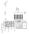
- FIG. 1is a schematic diagram of an embodiment of a well site 100 that comprises a wellhead 101 and a mobile fracturing system 103 .
- a mobile fracturing system 103may perform fracturing operations to complete a well and/or transform a drilled well into a production well.
- the well site 100may be a site where operators are in the process of drilling and completing a well. Operators may start the well completion process with vertical drilling, running production casing, and cementing within the wellbore. The operators may also insert a variety of downhole tools into the wellbore and/or as part of a tool string used to drill the wellbore.
- fracturing operations for well site 100may last several days.
- the mobile fracturing system 103may comprise a mobile source of electricity 102 configured to generate electricity by converting hydrocarbon fuel, such as natural gas, obtained from one or more other sources (e.g., a producing wellhead) at well site 100 , from a remote offsite location, and/or another relatively convenient location near the mobile source of electricity 102 . Improving mobility of the mobile fracturing system 103 may be beneficial because fracturing operations at a well site typically last for several days and the fracturing equipment is subsequently removed from the well site after completing the fracturing operation.
- hydrocarbon fuelsuch as natural gas
- the mobile source of electricity 102may supply electric power to fracturing equipment within the mobile fracturing system 103 that may include, but is not limited to, at least one switch gear transport 112 , a plurality of drive power transports 104 , at least one auxiliary power transport 106 , at least one blender transport 110 , at least one data van 114 and a plurality of fracturing pump transports 108 that deliver fracturing fluid through wellhead 101 to subsurface geological formations.
- the switch gear transport 112may receive the electricity generated from the mobile source of electric power 102 via one or more electrical connections. In one embodiment, the switch gear transport 112 may use 13.8 kilovolts (KV) electrical connections to receive power from the mobile source of electric power 102 .
- KVkilovolts
- the switch gear transport 112may comprise a plurality of electrical disconnect switches, fuses, transformers, and/or circuit protectors to protect the fracturing equipment.
- the switch gear transport 112may transfer the electricity received from the mobile source of electricity 102 to the drive power transports 104 and auxiliary power transports 106 .
- the auxiliary power transport 106may comprise a transformer and a control system to control, monitor, and provide power to the electrically connected fracturing equipment.
- the auxiliary power transport 106may receive the 13.8 KV electrical connection and step down the voltage to 4.8 KV, which is provided to other fracturing equipment, such as the fracturing pump transport 108 , the blender transport 110 , sand storage and conveyor, hydration equipment, chemical equipment, data van 114 , lighting equipment, and any additional auxiliary equipment used for the fracturing operations.
- the auxiliary power transport 106may step down the voltage to 4.8 KV rather than other voltage levels, such as 600 V, in order to reduce cable size for the electrical connections and the amount of cabling used to connect the mobile fracturing system 103 .
- the control systemmay be configured to connect to a control network system such that the auxiliary power transport 106 may be monitored and/or controlled from a distant location, such as the data van 114 or some other type of control center.
- the drive power transports 104may be configured to monitor and control one or more electrical motors located on the fracturing pump transports 108 via a plurality of connections, such as electrical connections (e.g., copper wires), fiber optics, wireless, and/or combinations thereof. The connections are omitted from FIG. 1 for clarity of the drawing.
- the drive power transports 104may be part of the control network system, where each of the drive power transports 104 comprise one or more variable frequency drives (VFDs) used to monitor and control the prime movers on the fracturing pump transports 108 .
- the control network systemmay communicate with each of the drive power transports 104 to monitor and/or control each of the VFDs.
- the VFDsmay be configured to control the speed and torque of the prime movers by varying the input frequency and voltage to the prime movers.
- each of the drive power transports 104may be configured to drive a plurality of the fracturing pump transports 108 .
- Other drive power transport to fracturing pump transport ratiosmay be used as desired.
- the drive power transports 104may comprise air filters and blowers that intake ambient air to cool the VFDs.
- Other embodiments of the drive power transports 104may use an air conditioning units and/or water cooling to regulate the temperature of the VFDs.
- the fracturing pump transport 108may receive the electric power received from the drive power transport 104 to power a prime mover.
- the prime moverconverts electric power to mechanical power for driving one or more pumps.
- the prime movermay be a dual shaft electric motor that drives two different pumps.
- the fracturing pump transport 108may be arranged such that one pump is coupled to opposite ends of the dual shaft electric motor and avoids coupling the pumps in series. By avoiding coupling the pump in series, the fracturing pump transport 108 may continue to operate when either one of the pumps fails or have been removed from the fracturing pump transport 108 .
- repairs to the pumpsmay be performed without disconnecting the system manifolds that connect the fracturing pump transport 108 to other fracturing equipment within the mobile fracturing system 103 and wellhead 101 . Details regarding implementing the fracturing pump transport 108 are discussed in more detail in FIGS. 7A-7B .
- the blender transport 110may receive the electric power fed through the auxiliary power transport 106 to power a plurality of electric blenders.
- a plurality of prime moversmay drive one or more pumps that pump source fluid and blender additives (e.g., sand) into a blending tub, mix the source fluid and blender additives together to form fracturing fluid, and discharge the fracturing fluid to the fracturing pump transport 108 .
- the electric blendermay be a dual configuration blender that comprises electric motors for the rotating machinery that are located on a single transport, which is described in more detail in U.S. Patent Application Publication No. 2012/0255734, filed Apr. 6, 2012 by Todd Coli et al.
- a plurality of enclosed mixer hoppersmay be used to supply the proppants and additives into a plurality of blending tubs.
- the electric blender that comprises the enclosed mixer hoppersare discussed in more detail in FIGS. 9A and 9B .
- the data van 114may be part of a control network system, where the data van 114 acts as a control center configured to monitor and provide operating instructions in order remotely operate the blender transport 110 , the mobile source of electricity 102 , and fracturing pump transport 108 and/or other fracturing equipment within the mobile fracturing system 103 .
- the data van 114may communicate via the control network system with the VFDs located within the drive power transports 104 that operate and monitor the health of the electric motors used to drive the pumps on the fracturing pump transports 108 .
- the data van 114may communicate with the variety of fracturing equipment using a control network system that has a ring topology. A ring topology may reduce the amount of control cabling used for fracturing operations and increase the capacity and speed of data transfers and communication. Details regarding implementing the control network system are discussed in more detail in FIG. 10 .
- FIG. 1Other fracturing equipment shown in FIG. 1 , such as gas conditioning transport, water tanks, chemical storage of chemical additives, hydration unit, sand conveyor, and sandbox storage are known by persons of ordinary skill in the art, and therefore are not discussed in further detail.
- one or more of the other fracturing equipment shown in FIG. 1may be configured to receive power generated from the mobile source of electricity 102 .
- one or more embodiments of the mobile fracturing system 103may not include the use of a missile that receives low-pressure fluid and releases high-pressure fluid towards the wellhead 101 .
- the control network system for the mobile fracturing system 103may remotely synchronizes and/or slaves the electric blender of the blender transport 110 with the electric motors of the fracturing pump transports 108 .
- the electric blendersmay perform rate changes to the pump rate change mounted on the fracturing pump transports 108 .
- the electric blender within a blender transport 110may also automatically compensate its rate and ancillary equipment, such as the sand conveyor, to accommodate the rate change. Manual commands from an operator may not be used to perform the rate change.
- FIG. 2is a schematic diagram an embodiment of a well site 200 that includes a mobile source of electricity 204 that comprises three transports for the mobile fracturing system 202 .
- the mobile fracturing system 202may be substantially similar to mobile fracturing system 103 , except that mobile fracturing system comprises an auxiliary gas turbine generator transport 206 .
- the auxiliary gas turbine generator transport 206may be configured to provide power to ignite, start, or power on the mobile source of electricity 204 and/or provide ancillary power where peak electric power demand exceeds the electric power output of a gas turbine generator transport.
- the auxiliary gas turbine generator transportmay comprise a smaller, gas turbine or diesel generator that generates less power (e.g., provides about 1-8 MW of electric power) than the one used in the gas turbine generator transport. Additionally or alternatively, the auxiliary gas turbine generator transport 206 may provide testing, standby, peaking, and/or other emergency backup power functionality for the mobile fracturing system 202 .
- FIG. 2illustrates that the mobile fracturing system 202 arranges and positions the drive power transport 104 and the auxiliary power transport 106 in an orientation that is about parallel to the switch gear transport 112 and the fracturing pump transports 108 . Positioning the drive power transport 104 and the auxiliary power transport 106 in a parallel orientation rather than about a perpendicular orientation as shown in FIG. 1 may be beneficial, for example reducing the foot print of the mobile fracturing system 202 . Moreover, FIG. 2 also illustrates that a fuel source 208 , such as natural gas from a producing wellhead, may be located at the well site and be used by the mobile source of electricity 204 to generate electricity.
- a fuel source 208such as natural gas from a producing wellhead
- FIGS. 1 and 2illustrate a specific configuration for a mobile fracturing system 103 at a well site 100
- the disclosureis not limited to that application and/or the specific embodiment illustrated in FIGS. 1 and 2 .
- embodiments of the present disclosuremay include a plurality of wellheads 101 , a plurality of blender transports 110 , and a plurality of auxiliary power transports 106 .
- the mobile source of electricity 102is not limited for use in a fracturing operation and may be applicable to power other types of equipment and devices not typically used in a fracturing operation.
- FIGS. 1 and 2is only an example to facilitate ease of description and explanation.
- FIG. 3is a schematic diagram an embodiment of a well site 300 that includes two wellheads 101 and two data vans 114 .
- the two data vans 114may be part of the control network system that simultaneously monitors and provides operating instructions to the two different wellheads 101 .
- An additional blender transport 110may be added to provide fracturing fluid to fracturing pump transports 108 used to fracture the subsurface geological structure underneath the second wellhead 101 .
- FIG. 3illustrates that both wellheads 101 are located on the same well site 300 , other embodiments may have the wellheads 101 located at different well sites.
- the mobile source of electricitymay be part of the mobile fracturing system used at a well site as described in FIGS. 1-3 .
- the mobile source of electricitymay be configured to be transportable to different locations (e.g., different well sites) along with other fracturing equipment (e.g., fracturing pump transports) that are part of the mobile fracturing system and may not be left behind after completing fracturing operations.
- the mobile source of electricitymay include at least two different transports that improve mobility of the dedicated electric power by simplifying and minimizing the operations for the mobilization and de-mobilization process.
- the mobile source of electricitymay improve mobility by enabling a mobilization and de-mobilization time period of about 24 hours.
- the mobile source of electricityalso incorporates a two transport footprint, where the same two transport system may be used for transportation and operation modes.
- FIGS. 4A-6illustrate embodiments of implementing a mobile source of electricity using two different transports
- other embodiments of the mobile source of electricitymay mount the gas turbine generator, air inlet filter housing, gas turbine exhaust stack, and other components shown in FIGS. 4A-6 on a different number of transports (e.g., all on one transport or more than two transports).
- the mobile source of electricitybe designed to unitize and mobilize a gas-turbine and generator adapted to convert hydrocarbon fuel, such as natural gas, into electricity.
- FIGS. 4A and 4Bare schematic diagrams of an embodiment of the gas turbine generator transport 400 .
- FIG. 4Aillustrates a side-profile view of the gas turbine generator transport 400 with a turbine enclosure 402 that surrounds components within the gas turbine generator transport 400 and includes cavities for the inlet plenum 404 , exhaust collector 406 , and an enclosure ventilation inlet 418 .
- FIG. 4Billustrates a side-profile view of the gas turbine generator transport 400 that depicts the components within the turbine enclosure 402 . As shown in FIG.
- the gas turbine generator transport 400may comprise the following equipment: (1) an inlet plenum 404 ; (2) a gas turbine 407 (e.g., General Electric (GE) 2500); (3) an exhaust collector 406 ; (4) a generator 408 ; (5) a generator breaker 410 ; and (6) a control system 420 .
- GEGeneral Electric
- Other components not shown in FIG. 4B , but which may also be located on the gas turbine generator transport 400include a turbine lube oil system, a fire suppression system, and a generator lube oil system.
- the gas turbine generator transport 400includes the gas turbine 407 to generate mechanical energy (i.e., rotation of a shaft) from a hydrocarbon fuel source, such as natural gas, liquefied natural gas, condensate, and/or other liquid fuels.
- a hydrocarbon fuel sourcesuch as natural gas, liquefied natural gas, condensate, and/or other liquid fuels.
- the gas turbine shaftis connected to the generator 408 such that the generator 408 converts the supplied mechanical energy from the rotation of the shaft to produce electric power.
- the gas turbine 407may be a gas turbine, such as the GE LM2500 family of gas turbines, the Pratt and Whitney FT8 gas turbines, or any other gas turbine that generates enough mechanical power for a generator 408 to power fracturing operations at one or more well sites.
- the generator 408may be a Brush BDAX 62-170ER generator or any other generator configured to generate electric power for fracturing operations at one or more well sites.
- the gas turbine 407 and generator 408 combination within a gas turbine generator transport 400may generate electric power from a range of at least about 15 megawatt (MW) to about 35 MW.
- MWmegawatt
- Other types of gas-turbine generators with power ranges greater than about 35 MW or less than about 15 MWmay also be used depending on the amount of power needed at the well sites.
- the gas turbine 407may be configured to fit within a dimension of about 14.5 feet long and about four feet in diameter and/or the generator 408 may be configured to fit within a dimension of about 18 feet long and about 7 feet wide.
- the generator 408may be housed within the turbine enclosure 402 that includes air ventilation fans internal to the generator 408 that draws air into the air inlet located on the front and/or back of the generator 408 and discharges air out on the sides via the air outlets 414 .
- Other embodimentsmay have the air outlets positioned on different locations of the enclosure for the generator 408 .
- the air inletmay be inlet louvres and the air outlets may be outlet louvres that protect the generator from the weather elements.
- a separate generator ventilation stack unitmay be mounted on the top of the gas turbine generator transport 400 .
- the turbine enclosure 402may also comprise gas turbine inlet filter(s) configured to provide ventilation air and combustion air via one or more inlet plenums 404 to the gas turbine 407 . Additionally, enclosure ventilation inlets 418 may be added to increase the amount of ventilation air.
- the ventilation airmay be air used to cool the gas turbine 407 and ventilate the gas turbine enclosure 402 .
- the combustion airmay be the air that is supplied to the gas turbine 407 to aid in the production of the mechanical energy.
- the inlet plenum 404may be configured to collect the intake air from the gas turbine inlet filter and supply the intake air to the gas turbine.
- the exhaust collector 406may be configured to collect the air exhaust from the gas turbine and supply the exhaust air to the gas turbine exhaust stack.
- the air inlet filter housing and the gas turbine exhaust stackare configured to be connected from at least one of the sides of the turbine enclosure 402 , as opposed to connecting both the air inlet filter housing and the gas turbine exhaust stack on the top of the turbine enclosure 402 or connecting the air inlet filter housing at one end of the gas turbine generator transport 400 and connecting the exhaust collector from the side of the turbine enclosure 402 .
- the air inlet filter housing and gas turbine exhaust stack from the inlet and exhaust transportmay connect with the turbine enclosure 402 using one or more expansion connections that extend from one or both of the transports, located at the sides of the turbine enclosure 402 .
- connectionmay be used that provides coupling between the turbine enclosure 402 and the air inlet filter housing and gas turbine exhaust stack without using a crane, forklift, and/or any other external mechanical means to connect the expansion connections in place and/or to connect the air inlet filter housing and gas turbine exhaust stack to the side of the turbine enclosure 402 .
- the expansion connectionsmay comprise a duct and/or an expansion joint to connect the air inlet filter housing and gas turbine exhaust stack to the turbine enclosure 402 .
- the routing of the air inlet filter housing and gas turbine exhaust stack via the sides of the turbine enclosure 402may provide a complete aerodynamic modeling where the inlet air flow and the exhaust air flow are used to achieve the gas turbine nameplate output rating. The inlet and exhaust transport is discussed in more detail later in FIGS. 5A and 5B .
- the gas turbine generator transport 400 in FIGS. 4A and 4Bmay have a maximum height of about 13 feet and 6 inches, a maximum width of about 8 feet and 6 inches, and a maximum length of about 66 feet. Further, the gas turbine generator transport 400 may comprise at least three axles used to support and distribute the weight on the gas turbine generator transport 400 . Other embodiments of the gas turbine generator transport 400 may be transports that exceed three axles depending on the total transport weight. The dimensions and the number of axles may be adjusted to allow for the transport over roadways that typically mandate certain height, length, and weight restrictions.
- the gas turbine 407 and generator 408may be mounted to an engineered transport frame 416 , a sub-base, sub-skid, or any other sub-structure used to support the mounting of gas turbine 407 and generator 408 .
- the single engineered transport framemay be used to align the connections between the gas turbine 407 , the generator 408 , the inlet plenum 404 and the exhaust collector 406 and/or lower the gas turbine and generator by configuring for a flush mount to the single engineered transport frame 416 .
- the single engineered transport frame 416may allow for easier alignment and connection of the gas turbine 407 and generator 408 compared to using separate sub-base for the gas turbine 407 and generator 408 .
- Other embodiments of the gas turbine generator transport 400may use a plurality of sub-bases, for example, mounting the gas turbine 407 on one sub-base and mounting the generator 408 on another sub-base.
- FIG. 4Billustrates that the generator breaker 410 and control system 420 may be located on the gas turbine generator transport 400 .
- the generator breaker 410may comprise one or more circuit breakers that are configured to protect the generator 408 from current and/or voltage fault conditions.
- the generator breaker 410may be a medium voltage (MV) circuit breaker switchboard.
- the generator breakermay be about three panels, two for the generator and one for a feeder that protect relays on the circuit breaker.
- the generator breaker 410may be vacuum circuit breaker.
- the control system 420may be configured to control, monitor, regulate, and adjust the power output of the gas turbine 407 and generator 408 .
- control system 420may monitor and balance the load produced by the fracturing operations by generating enough electric power to match the load demands.
- the control system 420may also be configured to synchronize and communicate with a control network system that allows a data van or other computing systems located in a remote location (e.g., off the well site) to control, monitor, regulate, and adjust power output of the generator 408 .
- FIG. 4Billustrates that the generator breaker 410 and/or control system 420 may be mounted on the gas turbine generator transport 400 , other embodiments of the mobile source of electricity may mount the generator breaker 410 and/or control system 420 in other locations (e.g. switch gear transport).
- FIGS. 4A and 4BOther equipment that may also be located on the gas turbine generator transport 400 , but are not shown in FIGS. 4A and 4B include the turbine lube oil system, gas fuel valves, generator lube oil system, and fire suppression system.
- the lube oil systems or consoleswhich generally refer to both the turbine lube oil system and generator lube oil system within this disclosure, may be configured to provide a generator and turbine lube oil filtering and cooling systems.
- the turbine lube oil console area of the transportmay also contain the fire suppression system, which may comprise sprinklers, water mist, clean agent, foam sprinkler, carbon dioxide, and/or other equipment used to suppress a fire or provide fire protection for the gas turbine 407 .
- the mounting of the turbine lube oil consoles and the fire suppression system onto the gas turbine generator transport 400reduces this transport's footprint by eliminating the need for an auxiliary transport and connections for the turbine and generator lube oil, filtering, cooling systems and the fire suppression system to the gas turbine generator transport.
- the turbine and generator lube oil systemsmay be mounted on a skid that is located underneath the generator 408 or any other location on the gas turbine generator transport 400 .
- FIGS. 5A and 5Bare schematic diagrams of embodiments of an inlet and exhaust transport 500 .
- FIG. 5Adepicts the inlet and exhaust transport 500 while in transportation mode
- FIG. 5Bdepicts the inlet and exhaust transport 500 while in operational mode.
- the inlet and exhaust transports 500include an air inlet filter housing 502 and a gas turbine exhaust stack 504 .
- one or more gas turbine inlet filters and ventilation fansmay be located within or housed in the air inlet filter housing 302 .
- FIGS. 5A and 5Billustrate that the air inlet filter housing 502 may be mounted on the inlet and exhaust transport 500 at a fixed location.
- Other embodiments of the inlet and exhaust transport 500may mount the air inlet filter housing 502 with a configuration such that the air inlet filter housing 502 may slide in one or more directions when transitioning between operational mode and transportation mode.
- the air inlet filter housing 502may slide out for operational mode and slide back for transport mode. Sliding the air inlet filter housing 502 may be used to align the air inlet filter housing 502 with the inlet plenum of the gas turbine enclosure mounted on the gas turbine generator transport.
- the air inlet filter housing 502may be mounted on a turntable with the ability to engage the inlet plenum of the gas turbine enclosure mounted on the gas turbine generator transport.
- the air inlet filter housing 502may comprise a plurality of silencers that reduce noise.
- the different embodiments for mounting the air inlet filter housing 502may depend on the amount of clean air and the air flow dynamics needed to supply the gas turbine for combustion.
- the gas turbine exhaust stack 504may comprise the gas turbine exhaust 508 , an exhaust extension 506 configured for noise control, and an exhaust end connector 510 .
- the exhaust extension 506may comprise a plurality of silencers that reduce noise from the inlet and exhaust transport 500 .
- the gas turbine exhaust stack 504may be mounted to initially lie on its side during transportation mode. In operational mode, the gas turbine exhaust stack 504 may be rotated up without using external mechanical means such that the gas turbine exhaust stack 504 is mounted to the inlet and exhaust transport 500 on its base and in the upright position.
- the gas turbine exhaust stack 504may be positioned using hydraulics, pneumatics, and/or electric motors such that it aligns and connects with the exhaust end connector 510 and exhaust collector of the gas turbine enclosure shown in FIGS. 4A and 4B .
- the exhaust end connector 510may be adjusted to accommodate and align the gas turbine exhaust stack 504 with the exhaust collector of the gas turbine enclosure. In operational mode, the exhaust end connector 510 may move forward in a side direction, which is in the direction toward the gas turbine enclosure. The exhaust end connector 510 may move backward in the side direction, which is in the direction away from the gas turbine enclosure, when transitioning to the transportation mode.
- Other embodiments of the gas turbine exhaust stack 504may have the gas turbine exhaust 508 and the exhaust end connector 510 connected as a single component such that the exhaust end connector 510 and the gas turbine exhaust stack 504 are rotated together when transitioning between the transportation and operational modes.
- the gas turbine exhaust stack 504may be sectioned into a first section and a second section.
- the first sectionmay correspond to the gas turbine exhaust 508 and the second section may correspond to the exhaust extension 506 .
- the first section of the gas turbine exhaust stack 508may be in the upright position and the second section of the gas turbine exhaust stack 506 may be mounted adjacent to the first section of the gas turbine exhaust for transport.
- the first section and the second sectionmay be hinged together such that the second section may be rotated up to stack on top of the first section for operation.
- the gas turbine exhaust stack 504may be configured such that the entire gas turbine exhaust stack 504 may be lowered or raised while mounted on the inlet and exhaust transport 500 .
- the air inlet filter housing 502 and gas turbine exhaust stack 504may be transported on separate transports and subsequently crane lifted onto the top of gas turbine enclosure and mounted on the gas turbine generator transport during operation mode.
- the separate transports to carry the air inlet filter housing 502 and gas turbine exhaust stack 504may not be used during operational mode.
- the inlet and exhaust transportmay be positioned alongside the gas turbine generator transport and subsequently connect the air inlet and exhaust plenums for operations.
- the resultis having a relatively quick rig-up and/or rig-down that eliminates the use of heavy lift cranes, forklifts, and/or any other external mechanical means at the operational site.
- FIG. 6is a schematic diagram of an embodiment of the two transport mobile electric power source 600 when in operational mode.
- FIG. 6illustrates a top-down-view of the coupling between the inlet and exhaust transport 500 and the gas turbine transport 400 during operational mode.
- the exhaust expansion connection 602may move and connect (e.g., using hydraulics) to the exhaust end connector 510 without using external mechanical means in order to connect the gas turbine exhaust stack of the inlet and exhaust transport with the exhaust collector of the gas turbine generator transport.
- the inlet expansion connections 604may move and connect the air inlet filter housing of the inlet and exhaust transport and the inlet plenum of the gas turbine generator transport.
- the two transports 400 and 500may be parked at a predetermined orientation and distance such that the exhaust expansion connection 602 and inlet expansion connections 604 are able to connect the two transports 400 and 500 .
- each of the transports 400 and 500may include a hydraulic walking system.
- the hydraulic walking systemmay move and align transport 500 into a position without attaching the two transports 400 and 500 to transportation vehicles (e.g., a tractor or other type of motor vehicle).
- the hydraulic walking systemmay comprise a plurality of outriggers and/or support feet 412 used to move transport 400 and/or transport 500 back and forth and/or sideways.
- the hydraulic walking systemmay comprise a first hydraulic cylinder that lifts the transport and a second hydraulic cylinder that moves the transport in the designated orientation or direction.
- a hydraulic walking system on the transportincreases mobility by reducing the precision needed when parking the two transports next to each other.
- FIG. 11is a flow chart of an embodiment of a method 1100 to provide a mobile source of electricity for fracturing operations.
- Method 1100may start at block 1102 by transporting a mobile source of electricity with other fracturing equipment to a well site that comprises a non-producing well.
- Method 1100may then move to block 1104 and convert the mobile source of electricity from transportation mode to operational mode.
- the same transportsmay be used during the conversation from transportation mode to operational mode. In other words, transports are not added and/or removed when setting up the mobile source of electricity for operational mode.
- method 1100be performed without the use of a forklift, crane, and/or other external mechanical means to transition the mobile source of electricity into operational mode.
- the conversion process for a two transport traileris described in more detail in FIGS. 4A-6 .
- Method 1100may then move to block 1106 and generate electricity using the mobile source of electricity to power fracturing operations at one or more well sites.
- method 1100may generate electricity by converting hydrocarbon fuel into electricity using a gas turbine generator.
- Method 1100may then move to block 1108 and convert the mobile source of electricity from operational mode to transportation mode. Similar to block 1104 , the conversion process for block 1108 may use the same transports without using a forklift, crane, and/or other external mechanical means to transition the mobile source of electricity back to transportation mode.
- Method 1100may then move to block 1110 to remove the mobile source of electricity along with other fracturing equipment from the well site once fracturing operations are completed.
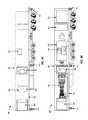
- FIGS. 7A and 7Bare schematic diagrams of embodiments of a fracturing pump transport 700 powered by the mobile source of electricity as described in FIGS. 4A-6 .
- the fracturing pump transport 700may include a prime mover 704 powering two separate pumps 702 A and 702 B.
- a fracturing operationmay reduce the amount of pump transports, prime movers, variable frequency drives (VFD's), ground iron, suction hoses, and/or manifold transports.
- VFD'svariable frequency drives
- FIG. 7A and 7Billustrates that the fracturing pump transport 700 supports a single prime mover 704 power two separate pumps 702 A and 702 B
- other embodiments of the fracturing pump transport 700may include a plurality of prime movers 704 that each power the pumps 702 A and 702 B.
- a “lay-down” trailer 710 designmay provide mobility, improved safety, and enhanced ergonomics for crew members to perform routine maintenance and operations of the pumps as the “lay-down” arrangement positions the pumps lower to the ground as the main trailer beams are resting on the ground for operational mode.
- the “lay-down” trailer 710has an upper section above the trailer axles that could hold or have mounted the fracturing pump trailer power and control systems 708 .
- the fracturing pump trailer power and control system 708may comprise one or more electric drives, transformers, controls (e.g., a programmable logic controller (PLC) located on the fracturing pump transport 700 ), and cables for connection to the drive power trailers and/or a separate electric pumper system.
- PLCprogrammable logic controller
- the electric drivesmay provide control, monitoring, and reliability functionality, such as preventing damage to a grounded or shorted prime mover 704 and/or preventing overheating of components (e.g., semiconductor chips) within the electric drives.
- the lower sectionwhich may be positioned lower than the trailer axles, may hold or have mounted the prime mover 704 and the pumps 702 A and 702 B attached on opposite sides of each other.
- the prime mover 704may be a dual shaft electric motor that has a motor shaft that protrudes on opposite sides of the electric motor.
- the dual shaft electric motormay be any desired type of alternating current (AC) or direct current (DC) motor.
- the dual shaft electric motormay be an induction motor and in another embodiment the dual shaft electric motor may be a permanent magnet motor.
- Other embodiments of the prime mover 704may include other electric motors that are configured to provide about 5,000 HP or more.
- the dual shaft electric motormay deliver motor power in a range from about 1,500 HP to about 10,000 HP.
- the dual shaft electric motormay be about a 5,000 HP rated electric motor or about a 10,000 HP electric motor.
- the prime mover 704may be driven by at least one variable frequency drive that is rated to a maximum of about 5,000 HP and may receive electric power generated from the mobile source of electric power.
- one side of the prime mover 704drives one pump 702 A and the opposite side of the prime mover 704 drives a second pump 702 B.
- the pumps 702 A and 702 Bare not configured in a series configuration in relation to the prime mover 704 .
- the prime mover 704independently drives each pump 702 A and 702 B such that if one pump fails, it can be disconnected and the other pump can continue to operate.
- the prime mover 704which could be a dual shaft electric motor, eliminates the use of diesel engines and transmissions. Moreover, using a dual shaft electric motor on a transport may prevent dissonance or feedback when transferring power to the pumps.
- the prime mover 704may be configured to deliver at least about 5,000 HP distributed between the two pumps 702 A and 702 B.
- prime mover 704which may be a dual shaft electric motor, may provide about 2,500 HP to one of the pumps 702 A and about 2,500 HP to the other pump 702 B in order to deliver a total of about 5,000 HP.
- Other embodimentsmay have the prime mover 704 deliver less than 5,000 HP or more than 5,000 HP.
- the prime mover 704may deliver a total of about 3,000 HP by delivering about 1,500 HP to one of the pumps and about 1,500 HP to the other pump.
- the prime mover 704may deliver a total of about 10,000 HP by delivering about 5,000 HP to one of the pumps 702 A and about 5,000 HP to another pump 702 B.
- the prime mover 704may operate at HP ratings of about 3,000 HP, 3,500 HP, 4,000 HP, 4,500 HP, 5,000 HP, 5,200 HP, 5,400 HP, 6,000 HP, 7,000 HP, 8,000 HP, 9,000 HP, and/or 10,000 HP.
- the fracturing pump transport 700may reduce the footprint of fracturing equipment on a well-site by placing two pumps 702 A and 702 B on a single transport. Larger pumps may be coupled to a dual shaft electric motor that operates with larger horse power to produce additional equipment footprint reductions.
- each of the pumps 702 A and 702 Bmay be quintiplex pumps located on a single transport. Other embodiments may include other types of plunger style pumps, such as triplex pumps.
- the pumps 702 A and 702 Bmay each operate from a range of about 1,500 HP to about 5,000 HP.
- each of the pumps 702 A and 702 Bmay operate at HP ratings of about 1,500 HP, 1,750 HP, 2,000 HP, 2,250 HP, 2,500 HP, 2,600 HP, 2,700 HP, 3,000 HP, 3,500 HP, 4,000 HP, 4,500 HP, and/or 5,000 HP.
- the pumps 702 A and 702 Bmay not be configured in a series configuration where the prime mover 704 drives a first pump 702 A and the first pump 702 B subsequently drives a second pump 702 B.
- FIG. 7Aalso illustrates that each pump 702 A and 702 B, which may also be generally referred to in this disclosure as pump 702 , is mounted on the fracturing pump transport 700 with the same orientation.
- each pump 702is mounted such that the fluid end assembly 716 for each pump 702 is facing the same side of the fracturing pump transport 700 .
- the power end assembly 718 for each pump 702is facing the same side of the fracturing pump transport 700 .
- the fluid end assembly 716 and power end assembly 718are located on opposite sides of the fracturing pump transport 700 . As shown in FIG.
- both the fluid end assembly 716 and power end assembly 718 of a pump 702may face sides of the fracturing pump transport 700 that are about orthogonal or perpendicular to the front end 720 and back end 722 of the fracturing pump transport 700 .
- Having the fluid end side 716 of each pump 702 face the same side of the fracturing pump transport 700may be beneficial by simplifying and reducing the amount of plumbing used to route both the low pressure fluid line and high pressure fluid line into and out of the fracturing pump transport 700 .
- the fracturing pump transport 700may include plumbing that routes both the low pressure fluid lines and high pressure fluid lines on both sides of the fracturing pump transport 700 .
- the fracturing pump transport 700may include plumbing that routes both the low pressure fluid lines and high pressure fluid lines on both sides of the fracturing pump transport 700 .
- pump 702 A's and 702 B's fluid end assembly 716are facing the same side of the fracturing pump transport 700 , at least a majority of the plumbing that routes both the low pressure fluid lines and high pressure fluid lines could be located on one side of the fracturing pump transport 700 .
- one of the pumps 702may be configured with a right-side pinion while the other pump 702 (e.g., pump 702 A) is configured with a pinion located on the opposite side of the pump 702 , which can be referred to as a left-side pinion.
- a pump 702 with a right-side pinionmay be designated to mount to a specific side of the prime mover 704 , such as the side of the prime mover 704 facing the back end 722 (e.g., the end with trailer axles), and the pump 702 with a left-side pinion may be designated to mount on the other side of the prime mover 704 , such as the side of the prime mover 704 facing the front end 720 (e.g., trailer hitch).
- the pumps 702are located on opposite sides of the prime mover 704 , placing pinions on different sides of the pumps 702 allows the fluid end assembly 716 for each pump 702 to face the same side of the fracturing pump transport 700 .
- the fracturing pump transport 700may include one or more pumps 702 configured with a dual pinion 724 .
- a pump 702 with the dual pinion configurationwould include both a left-side pinion and a right-side pinion.
- FIG. 7Billustrates that each pump 702 A and 702 B has a dual pinion 724 , where the two pinion ends are located on opposite sides of each other.
- Having pumps 702 configured with a dual pinion 724provides additional flexibility compared to pumps 702 with either a right-side pinion or a left-side pinion.
- a pump 702 with a dual pinion 724may be able to mount on either side of the prime mover 704 while having the fluid end assembly 716 for each pump 702 face the same side of the fracturing pump transport 700 .
- Another advantage of having the fluid end assemblies 716 face the same side of the fracturing pump transport 700is to avoid damaging the pump 702 at different loads and/or requiring mounting of a custom fracturing pump.
- the pinions for pumps 702 A and 702 Bmay be rotating in opposite directions when driven by the prime mover 704 .
- a pinion, whether a right-pinion, left-pinion, or a dual pinion 724may be located within the power end assembly 718 and includes a pinion shaft and one or more pinion gears configured to generate rotational movement of the power end assembly 718 .
- the rotational movementmay generate torque that moves the plungers in the fluid end assembly 716 used to pump and pressurize fracturing fluid.
- a pinion gearmay interface with a bull gear that drives a crankshaft, which in turn moves the fluid end plungers.
- the pinion gear and the bull gearare commonly helical gears configured to engage with each other by rotating in a specified direction. If the pinion shaft, pinion gear, and bull gear are rotated in a direction opposite to the designed direction, the pinion gear may turn the bull gear until the pinion gear generates enough torque to break the bull gear and damage the pump 702 .
- one of the pumps 702would need to be customized to provide torque when the pinion rotates in a direction opposite of conventional fracturing pumps.
- Including a customized fracturing pump on the fracturing pump transport 700could not only lead to an increase in manufacturing cost, but also decrease operational and maintenance flexibility by requiring pumps 702 A and 702 B to be mounted on designated sides of the prime mover 704 .
- the prime mover 704 and each of the pumps 702 A and 702 Bmay be mounted on sub-assemblies configured to be isolated and allow for individual removal from the fracturing pump transport. In other words, the prime mover 704 and each of the pumps 702 A and 702 B can be removed from service and replaced without shutting down or compromising other portions of the fracturing system.
- the prime mover 704 and pumps 702 A and 702 Bmay be connected to each other via couplings that are disconnected when removed from the fracturing pump transport 700 .
- the prime mover sub-assemblymay be detached from the fracturing pump transport 700 without removing the two pumps 702 A and 702 B from the fracturing pump transport.
- pump 702 Acan be isolated from the fracturing pump transport 700 , removed and replaced by a new pump 702 A.
- an operatorcan isolate the different components from the fluid lines, and unplug, un-pin, and remove the prime mover 704 and/or the pumps 702 A and 702 B from the fracturing pump transport.
- each pump 702 A and 702 B sub-assemblymay be detached and removed from the fracturing pump transport 700 without removal of the other pump and/or the prime mover 704 .
- the fracturing pump transport 700may not need to be disconnected from the manifold system and driven out of the location. Instead, replacement prime mover 704 and/or the pumps 702 A and 702 B may be placed backed into the line and reconnected to the fracturing pump transport 700 .
- the two pumps 702 A and 702 Bmay be coupled to the prime mover 704 using a drive line assembly 706 that is adapted to provide remote operation that engages and/or disengages one or both pumps 702 A and 702 B from the prime mover 704 .
- the drive line assembly 706may comprise one or more couplings and one or more drive shafts.
- the drive line assembly 706may comprise a fixed coupling that connects to one of the pumps 702 A or 702 B, a keyed shaft 712 , and an engagement coupling (e.g., spline-tooth coupling 714 ).
- the keyed shaft 712may interconnect the fixed coupling (e.g., a flex coupling or universal joint-based coupling) to a spline-tooth coupling 714 that attaches to the prime mover 704 .
- the fixed couplingmay directly connect the keyed shaft 712 to the pinion of the pump or indirectly connect the keyed shaft 712 to the pinion of the pump using a pump drive shaft.
- the spline-tooth coupling 714may include a splined sliding sleeve coupling and a motor coupling that provides motor shaft alignment with the keyed shaft 712 .
- Hydraulic fluid and/or mechanical powermay be used to adjust the splined sliding sleeve coupling to engage and/or disengage the pumps 702 A and 702 B from the prime mover 704 .
- Other embodiments of couplings that may be used to engage and/or disengage the keyed shaft 712 from the prime mover 704may include torque tubes, air clutches, electro-magnetic clutches, hydraulic clutches, and/or other clutches and disconnects that have manual and/or remote operated disconnect devices.
- FIG. 13is a schematic diagram of an embodiment of a fracturing pump transport 1300 configured to remotely engage and/or disengage one or more pumps 702 from the prime mover 704 .
- the prime mover 704is a dual-shaft electric motor
- the fracturing pump transport 1300may use other types of electric motors, such an electric motor that has only one shaft extending outward.
- the fracturing pump transport 1300may comprise an engagement panel 1302 and a monitoring station 1304 , such as a human monitoring interface (HMI) station.
- the engagement panel 1302may include a control system that adjusts an engagement coupling to transition between an engaged and a disengaged position.
- the engagement panel 1302may include levers or switches that an operator may manually operate to engage or disengage the keyed shaft 712 from the motor shaft using the engagement coupling. Additionally or alternatively, the engagement panel 1302 may include electronic controllers that receive instructions from remote locations, such as a monitoring station 1304 , another location at the well site (e.g., data van), and/or off-site to engage and/or disengage the pumps 702 from the prime mover 704 . In response to receiving a remote command, the engagement panel 1302 may trigger the engagement and/or disengagement of one or more of the pumps from the prime mover 704 .
- the engagement panel 1302may trigger the engagement of pump 702 A and disengagement of pump 702 B.
- the remote commandmay also produce a result where both pumps 702 are disengaged or engaged with the prime mover.
- the engagement panel 1302may vary its mounting location on the fracturing pump transport 1300 and the control mechanism used to engage and/or disengage the pumps 702 from the prime mover 704 .
- FIG. 13illustrates the engagement panel 1302 is located at the front end of the fracturing pump transport 1300 , other embodiments could have the engagement panel 1302 located at other locations, such as being part of the trailer power and control systems 708 and/or closer in proximity to the trailer power and control systems 708 .
- the control mechanism implemented by the engagement panel 1302may be based on the type of engagement coupling used to engage or disengage the pumps 702 and prime mover 704 .
- the engagement panel 1302may be a hydraulic control bank, which is discussed in more detail in FIGS. 15A and 15 B that include hydraulic controllers (e.g., hydraulic and electronic control valves) that manage hydraulic fluid pressure when the engagement coupling is a splined tooth coupling.
- the monitoring station 1304may include hardware and/or software that allow an operator to manage and control (e.g., provide instructions) the engagement panel 1302 to engage and/or disengage the pumps 702 from the prime mover 704 .
- the monitoring station 1304may be configured with a safety control system that prevents the execution of engagement and/or disengagement instructions when the prime mover and/or pumps are operational.
- the monitoring station 1304may also include network components for receiving remote engagement or disengagement instructions by connecting to a control network system that communicates with other fracturing equipment and/or control systems. The control network system is described in more detail in FIG. 10 .
- the fracturing pump transport 1300may also include proximity sensors (not shown in FIG. 13 ) used to determine whether the engagement coupling is in an engagement or disengagement position when performing remote monitoring at the monitoring station 1304 , another location at the well site (e.g., data van), and/or off-site.
- the proximity sensorsmay be coupled to the engagement coupling and/or located in close proximity to the engagement coupling to determine whether the pumps 702 are engaged and/or disengaged with the prime mover 704 .
- Information obtained from the proximity sensorsmay also be useful in allowing the monitoring station 1304 and/or other control systems that are part of the control network system (e.g., data van) to determine the number of operating pumps (e.g., none, one, or two) for fracturing pump transport 1300 .
- An operator and/or control systemmay use the number of pumps to accurately measure the fluid pumping rate during operations.
- FIGS. 14A and 14Bare schematic diagrams of an embodiment of a drive line assembly 1400 used to remotely engage and/or disengage a pump from a prime mover.
- FIG. 14Aillustrates that the engagement coupling 1410 is in an engagement position while FIG. 14B illustrates that the engagement coupling 1410 is in a disengagement position.
- the engagement coupling 1410may translate the rotational movement from the motor shaft 1408 of the prime mover to the keyed shaft (e.g., a driveline shaft or pump pinion).
- the keyed shafte.g., a driveline shaft or pump pinion
- the engagement coupling 1410disengages the keyed shaft from the motor shaft 1408 of the prime mover such that the rotational movement is not translated to the keyed shaft even though the motor shaft 1408 continues to rotate.
- the keyed shaftwould be located underneath the shaft cover 1406 used to mount the proximity sensors 1404 A and 1404 B.
- FIGS. 14A and 14Balso illustrate that the engagement coupling 1410 includes a spline-tooth coupling with a sleeve that moves back in forth using hydraulic cylinders 1402 (e.g., hydraulic rams).
- hydraulic cylinders 1402e.g., hydraulic rams
- the spline-tooth couplingmay engage the keyed shaft and transfer rotational movement from the motor shaft 1408 to the keyed shaft.
- the spline-tooth couplingmay disengage the keyed shaft and isolate the rotational movement the motor shaft 1408 generates from the keyed shaft.
- Other embodimentsmay use mechanical power instead of hydraulic power to move the sleeves of the spline-tooth coupling.
- the motor shaft 1408may refer to one end of the dual shaft that protrudes out of the prime mover.
- the motor shaft 1408be a drive line shaft that is coupled to one end of the dual shaft of the prime mover.
- the engagement coupling 1410may directly or indirectly connect the keyed shaft engagement coupling 1410 to a prime mover.
- the drive line assembly 1400may also include one or more proximity sensors 1404 A and 1404 B to determine the position of the engagement coupling 1410 , and one or more fixed couplings 1412 used to directly or indirectly couple the keyed shaft with a pump pinion.
- the proximity sensor 1404 Amay detect when the engagement coupling 1410 is in an engagement position
- the proximity sensor 1404 Bmay detect when the engagement coupling 1410 has moved to a disengagement position.
- FIGS. 14A and 14Balso depict fixed couplings 1412 that couples the keyed shaft to a pump pinion.
- the drive line assembly 1400may vary the number of fixed couplings 1412 and intermediate drive shafts based on space availability, misalignment tolerances, and whether vibrations from the pump need to be deflected to avoid affecting the operation of the prime mover. Additionally, in one or more embodiments, the pump's pinion may move or walk slightly axially (e.g., 1/16ths of an inch). Having fixed couplings 1412 and intermediate drive shafts may allow the pump's pinion shaft to move or walk slightly without damaging the motor shaft and/or bearings of the prime mover. Examples of fixed couplings 1412 may include, but are not limited to, flex couplings and/or universal joint-based coupling.
- FIGS. 14A and 14Billustrate a specific embodiment of a drive line assembly 1400
- the disclosureis not limited to the specific embodiment illustrated in FIGS. 14A and 14B
- engagement coupling 1410may be implemented using other types of coupling, such as torque tubes, air clutches, electro-magnetic clutches, hydraulic clutches.
- the type of engagement coupling 1401may then determine what powers the engagement and/or disengagement operation, such as hydraulic, mechanical, and/or electric power.
- the engagement coupling 1410may be configured to statically and/or dynamically engage and/or disengage the keyed shaft from the motor shaft 1408 . In a static engagement and/or disengagement, the pumps and/or prime mover may not be operational when engagement or disengagement occurs.
- the motor shaft 1408is not rotating when performing static engagement and/or disengagement.
- the pumps, prime mover and/or motor shaft 1408are rotating when engagement and/or disengagement occurs.
- the drive line assembly 1400may use an air clutch to perform dynamic engagement or disengagement.
- FIGS. 14A and 14BThe use and discussion of FIGS. 14A and 14B is only an example to facilitate ease of description and explanation.
- FIG. 15Ais a schematic diagram of an embodiment of an engagement panel 1500 configured to cause remote engagement and/or disengagement of one or more pumps with a prime mover
- FIG. 15Bis a schematic diagram of an embodiment of a hydraulic control bank 1502 located within an engagement panel 1500 .
- FIG. 15Aillustrates that the engagement panel 1500 includes a hydraulic control bank 1502 with one or more hydraulic levers 1504 that operators may manually operate to trigger engagement and/or disengagement of one or more pumps from a prime mover.
- adjusting the hydraulic levers 1504may activate hydraulic control valves 1506 that adjust hydraulic fluid pressures to move an engagement coupling, such as a spline-tooth coupling, to an engagement and/or disengagement position.
- the hydraulic control bank 1502may also include electronic control valves 1508 that adjust hydraulic fluid pressures based on instructions received from a remote location, such as a monitoring station, another location at the well site (e.g., data van), and/or off-site.
- the electronic control valves 1508may include one or more electronic solenoids that adjust the hydraulic fluid pressures to engage and/or disengage one or more pumps from the prime mover.
- the engagement panel 1500may also be configured to prevent engagement and/or disengagement while the motor shaft of the prime mover is rotating (e.g., when an operator attempts to adjust the hydraulic levers and/or remote instructions are received) in instances the engagement coupling is configured to only perform static engagement and/or disengagement.
- FIG. 12is a flow chart of an embodiment of a method 1200 to pump fracturing fluid into a wellhead.
- Method 1200starts at block 1202 and receives electric power to power at least one prime mover.
- the prime movermay be a dual-shaft electric motor located on a fracturing pump transport as shown in FIGS. 7A and 7B .
- Method 1200may then move to block 1204 and receive fracturing fluid produced from one or more blenders.
- the blendersmay be electric blenders that includes enclosed mixer hoppers.
- Method 1200then moves to block 1206 and drives one or more pumps using the at least one prime mover to pressurize the fracturing fluid.
- the pumpsmay be positioned on opposite sides and may be both driven by a single shaft from the dual-shaft electric motor when the engagement couplings for both pumps are in engagement position.
- method 1200may drive the two pumps in a parallel configuration instead of a serial configuration. If one of the pumps are removed and/or disengaged, method 1200 may continue to drive the remaining pump.
- Method 1200may receive engagement and/or disengagement instructions manually and/or from a remote location to engage and/or disengaged the pumps prior to or while driving the pumps. Method 1200 may then move to block 1208 and pump the pressurized fracturing fluid into a wellhead.
- FIGS. 8A and 8Bare schematic diagrams of an embodiment of a blender transport 800 that includes an electric blender 806 .
- FIG. 8Aillustrates a top-down view of the blender transport 800 and
- FIG. 8Billustrates a side-profile view of the blender transport 800 .
- the blender transport 800may be powered by the mobile source of electricity as described in FIGS. 1-6 .
- the electric blender 806may be a dual configuration blender, as described in U.S. Patent Application Publication 2012/0255734, with a blending capacity of about 240 bpm.
- the dual configuration blendermay comprise electric motors for all rotating machinery and may be mounted on a single transport.
- the dual configuration blendermay have two separate blending units that are configured to be independent and redundant.
- any one or both the blending unitsmay receive a source fluid via inlet manifolds of the blending units.
- the source fluidmay originate from the same source or different sources.
- the source fluidmay subsequently be blended by any one or both of the blending tub and subsequently discharged out of any one or both outlet manifolds of the blending units.
- Other embodiments of the blender transport 800may be single configuration blender that includes a single blending unit.
- FIGS. 8A and 8Billustrate a “lay-down” trailer 802 design that provides mobility and improves ergonomics for the crew members that perform routine maintenance and operations of the electric blender 806 as the “lay-down” positions the blender tubs, pumps and piping lower to the ground level and the main trailer beams are resting on the ground for operational mode.
- the “lay-down” trailer 802may comprise an upper section above the trailer axles and a lower section below the trailer axles.
- the electric blender 806 and associated equipment on the trailermay be controlled and monitored remotely via a control system network.
- a blender control system 804that comprises a PLC, transformers and one or more variable frequency drives are mounted on upper section of the blender transport 800 .
- the networkmay interface and communicate with the PLC (e.g., provide operating instructions), and the PLC may subsequently control one or more variable frequency drives mounted on the blender trailer to drive one or more electric motors of the blender.
- a conventional blender transporttypically includes a station for an operator to manually operate the blender.
- the stationmay be removed from the blender transport 800 .
- a data vanmay act as a hub to provide the remote control and monitoring functions and instructions to the blender control system 804 .
- FIGS. 9A and 9Bare schematic diagrams of an embodiment of a blender transport 900 that includes an electric blender 902 with enclosed mixer hoppers 904 .
- FIG. 9Aillustrates a top-down view of the blender transport 900 and
- FIG. 9Billustrates a side-profile view of the blender transport 900 .
- the electric blender 902is substantially similar to the electric blender 806 except that the electric blender 902 uses enclosed mixer hoppers 904 to add proppants and additives to the blending tub.
- FIGS. 9A and 9Billustrate that the electric blender 902 is a dual configuration blender that includes two enclosed mixer hoppers 904 powered by two electric motors, where each of the electric motors may operate an enclosed mixer hopper 904 .
- Blenders that comprises open hoppers and augerstypically have the proppants (e.g., sand) and/or additives exposed to the weather elements. In situations where precipitation occurs at the well site, operators may cover the open hoppers and augers with drapes, tarps, and/or other coverings to prevent the precipitation from contaminating the proppants and/or additives.
- the enclosed mixer hopper 904replaces the open hopper and augers typically included in a blender (e.g., electric blender 806 in FIGS. 8A and 8B ) with enclosed mixer hoppers 904 ( FIGS. 9A and 9B ).
- the blender transport 900may have the advantages of dust free volumetric proppant measurement, dust free mixing of proppant and additives, moderate the transport of proppants, perform accurate volumetric measurements, increase proppant transport efficiency with low slip, prevent proppant packing from vibration, produce a consistent volume independent of angle of repose, and meter and blend wet sand.
- Other advantagesinclude the removal of gearboxes and increasing safety for operators with the enclosed drum.
- FIG. 10is a schematic diagram of an embodiment of a control network system 1000 used to monitor, control, and communicate with a variety of control systems located at one or more well sites.
- FIG. 10illustrates that the control network system 1000 may be in a ring-topology that interconnects the control center 1002 , blender transports 1004 , chemical additive unit 1006 , hydration unit 1008 , and fracturing pump transports 1012 .
- a ring topology networkmay reduce the amount of control cabling used for fracturing operations and increase the capacity and speed of data transfers and communication. Additionally, the ring topology may allow for two way communication and control by the control center 1002 for equipment connected to the control network system 1000 .
- control centermay be able to monitor and control the other fracturing equipment 1010 and third party equipment 1014 when added to the control network system 1000 , and for multiple pieces of equipment to communicate with each other.
- the other fracturing equipment 1010 and third party equipment 1014may be limited to one way communication where data is transmitted from the fracturing equipment 1010 and/or third party equipment 1014 to the control center 1002 , but not vice versa or between different pieces of equipment.
- control network system 1000may be a network, such as an Ethernet network that connects and communications with the individual control systems for each of the fracturing equipment.
- the control center 1002may be configured to monitor, control, and provide operating instructions to the different fracturing equipment.
- the control center 1002may communicate with the VFDs located within the drive power transports 104 that operate and monitor the health of the electric motors used to drive the pumps on the fracturing pump transports 108 .
- the control center 1002may be one or more data vans. More data vans may be used when the fracturing operations include fracturing more than two wellheads simultaneously.
Landscapes
- Engineering & Computer Science (AREA)
- General Engineering & Computer Science (AREA)
- Mechanical Engineering (AREA)
- Physics & Mathematics (AREA)
- Fluid Mechanics (AREA)
- Life Sciences & Earth Sciences (AREA)
- Geology (AREA)
- Mining & Mineral Resources (AREA)
- Environmental & Geological Engineering (AREA)
- General Life Sciences & Earth Sciences (AREA)
- Geochemistry & Mineralogy (AREA)
- Connection Of Motors, Electrical Generators, Mechanical Devices, And The Like (AREA)
Abstract
Description
Claims (18)
Priority Applications (6)
| Application Number | Priority Date | Filing Date | Title |
|---|---|---|---|
| US15/253,686US10378326B2 (en) | 2014-12-19 | 2016-08-31 | Mobile fracturing pump transport for hydraulic fracturing of subsurface geological formations |
| ARP160102674AAR106020A1 (en) | 2016-08-31 | 2016-09-01 | MOBILE TRANSPORT OF FRACTURING PUMP FOR HYDRAULIC FRACTURATION OF SUBSUPERFICIE GEOLOGICAL FORMATIONS |
| US16/294,786US11168554B2 (en) | 2014-12-19 | 2019-03-06 | Mobile fracturing pump transport for hydraulic fracturing of subsurface geological formations |
| ARP200102116AAR119508A2 (en) | 2016-08-31 | 2020-07-28 | MOBILE FRACTURATION PUMP TRANSPORTER VEHICLE FOR HYDRAULIC FRACTURATION OF UNDERGROUND GEOLOGICAL FORMATIONS |
| US17/500,525US11891993B2 (en) | 2014-12-19 | 2021-10-13 | Mobile fracturing pump transport for hydraulic fracturing of subsurface geological formations |
| US18/397,567US20240247646A1 (en) | 2014-12-19 | 2023-12-27 | Mobile fracturing pump transport for hydraulic fracturing of subsurface geological formations |
Applications Claiming Priority (3)
| Application Number | Priority Date | Filing Date | Title |
|---|---|---|---|
| US201462094773P | 2014-12-19 | 2014-12-19 | |
| US14/971,450US9534473B2 (en) | 2014-12-19 | 2015-12-16 | Mobile electric power generation for hydraulic fracturing of subsurface geological formations |
| US15/253,686US10378326B2 (en) | 2014-12-19 | 2016-08-31 | Mobile fracturing pump transport for hydraulic fracturing of subsurface geological formations |
Related Parent Applications (1)
| Application Number | Title | Priority Date | Filing Date |
|---|---|---|---|
| US14/971,450Continuation-In-PartUS9534473B2 (en) | 2014-12-19 | 2015-12-16 | Mobile electric power generation for hydraulic fracturing of subsurface geological formations |
Related Child Applications (1)
| Application Number | Title | Priority Date | Filing Date |
|---|---|---|---|
| US16/294,786ContinuationUS11168554B2 (en) | 2014-12-19 | 2019-03-06 | Mobile fracturing pump transport for hydraulic fracturing of subsurface geological formations |
Publications (2)
| Publication Number | Publication Date |
|---|---|
| US20160369609A1 US20160369609A1 (en) | 2016-12-22 |
| US10378326B2true US10378326B2 (en) | 2019-08-13 |
Family
ID=57587753
Family Applications (4)
| Application Number | Title | Priority Date | Filing Date |
|---|---|---|---|
| US15/253,686Active2036-04-13US10378326B2 (en) | 2014-12-19 | 2016-08-31 | Mobile fracturing pump transport for hydraulic fracturing of subsurface geological formations |
| US16/294,786Active2036-06-13US11168554B2 (en) | 2014-12-19 | 2019-03-06 | Mobile fracturing pump transport for hydraulic fracturing of subsurface geological formations |
| US17/500,525Active2036-05-11US11891993B2 (en) | 2014-12-19 | 2021-10-13 | Mobile fracturing pump transport for hydraulic fracturing of subsurface geological formations |
| US18/397,567PendingUS20240247646A1 (en) | 2014-12-19 | 2023-12-27 | Mobile fracturing pump transport for hydraulic fracturing of subsurface geological formations |
Family Applications After (3)
| Application Number | Title | Priority Date | Filing Date |
|---|---|---|---|
| US16/294,786Active2036-06-13US11168554B2 (en) | 2014-12-19 | 2019-03-06 | Mobile fracturing pump transport for hydraulic fracturing of subsurface geological formations |
| US17/500,525Active2036-05-11US11891993B2 (en) | 2014-12-19 | 2021-10-13 | Mobile fracturing pump transport for hydraulic fracturing of subsurface geological formations |
| US18/397,567PendingUS20240247646A1 (en) | 2014-12-19 | 2023-12-27 | Mobile fracturing pump transport for hydraulic fracturing of subsurface geological formations |
Country Status (1)
| Country | Link |
|---|---|
| US (4) | US10378326B2 (en) |
Cited By (91)
| Publication number | Priority date | Publication date | Assignee | Title |
|---|---|---|---|---|
| US20200048985A1 (en)* | 2018-08-10 | 2020-02-13 | Matthew Oehler | Proppant Dispensing System |
| US20200087997A1 (en)* | 2017-06-29 | 2020-03-19 | Typhon Technology Solutions, Llc | Electric power distribution for fracturing operation |
| US10598258B2 (en) | 2017-12-05 | 2020-03-24 | U.S. Well Services, LLC | Multi-plunger pumps and associated drive systems |
| US20200109617A1 (en)* | 2018-10-09 | 2020-04-09 | U.S. Well Services, LLC | Modular switchgear system and power distribution for electric oilfield equipment |
| US10648270B2 (en) | 2018-09-14 | 2020-05-12 | U.S. Well Services, LLC | Riser assist for wellsites |
| US10648311B2 (en) | 2017-12-05 | 2020-05-12 | U.S. Well Services, LLC | High horsepower pumping configuration for an electric hydraulic fracturing system |
| US10655435B2 (en) | 2017-10-25 | 2020-05-19 | U.S. Well Services, LLC | Smart fracturing system and method |
| US10686301B2 (en) | 2012-11-16 | 2020-06-16 | U.S. Well Services, LLC | Switchgear load sharing for oil field equipment |
| US10731561B2 (en) | 2012-11-16 | 2020-08-04 | U.S. Well Services, LLC | Turbine chilling for oil field power generation |
| US10815764B1 (en) | 2019-09-13 | 2020-10-27 | Bj Energy Solutions, Llc | Methods and systems for operating a fleet of pumps |
| US10895202B1 (en) | 2019-09-13 | 2021-01-19 | Bj Energy Solutions, Llc | Direct drive unit removal system and associated methods |
| US10927802B2 (en) | 2012-11-16 | 2021-02-23 | U.S. Well Services, LLC | System for fueling electric powered hydraulic fracturing equipment with multiple fuel sources |
| US10934824B2 (en) | 2012-11-16 | 2021-03-02 | U.S. Well Services, LLC | System for reducing vibrations in a pressure pumping fleet |
| US10947829B2 (en) | 2012-11-16 | 2021-03-16 | U.S. Well Services, LLC | Cable management of electric powered hydraulic fracturing pump unit |
| US10954770B1 (en) | 2020-06-09 | 2021-03-23 | Bj Energy Solutions, Llc | Systems and methods for exchanging fracturing components of a hydraulic fracturing unit |
| US10961914B1 (en) | 2019-09-13 | 2021-03-30 | BJ Energy Solutions, LLC Houston | Turbine engine exhaust duct system and methods for noise dampening and attenuation |
| US10961908B1 (en) | 2020-06-05 | 2021-03-30 | Bj Energy Solutions, Llc | Systems and methods to enhance intake air flow to a gas turbine engine of a hydraulic fracturing unit |
| US10968837B1 (en) | 2020-05-14 | 2021-04-06 | Bj Energy Solutions, Llc | Systems and methods utilizing turbine compressor discharge for hydrostatic manifold purge |
| US10989180B2 (en) | 2019-09-13 | 2021-04-27 | Bj Energy Solutions, Llc | Power sources and transmission networks for auxiliary equipment onboard hydraulic fracturing units and associated methods |
| US11002189B2 (en) | 2019-09-13 | 2021-05-11 | Bj Energy Solutions, Llc | Mobile gas turbine inlet air conditioning system and associated methods |
| US11009162B1 (en) | 2019-12-27 | 2021-05-18 | U.S. Well Services, LLC | System and method for integrated flow supply line |
| US11015536B2 (en) | 2019-09-13 | 2021-05-25 | Bj Energy Solutions, Llc | Methods and systems for supplying fuel to gas turbine engines |
| US11015594B2 (en) | 2019-09-13 | 2021-05-25 | Bj Energy Solutions, Llc | Systems and method for use of single mass flywheel alongside torsional vibration damper assembly for single acting reciprocating pump |
| US11022526B1 (en) | 2020-06-09 | 2021-06-01 | Bj Energy Solutions, Llc | Systems and methods for monitoring a condition of a fracturing component section of a hydraulic fracturing unit |
| US11028677B1 (en) | 2020-06-22 | 2021-06-08 | Bj Energy Solutions, Llc | Stage profiles for operations of hydraulic systems and associated methods |
| US11035207B2 (en) | 2018-04-16 | 2021-06-15 | U.S. Well Services, LLC | Hybrid hydraulic fracturing fleet |
| US11066915B1 (en) | 2020-06-09 | 2021-07-20 | Bj Energy Solutions, Llc | Methods for detection and mitigation of well screen out |
| US11067481B2 (en) | 2017-10-05 | 2021-07-20 | U.S. Well Services, LLC | Instrumented fracturing slurry flow system and method |
| US11070109B2 (en) | 2014-12-19 | 2021-07-20 | Typhon Technology Solutions, Llc | Mobile electric power generation for hydraulic fracturing of subsurface geological formations |
| US11066912B2 (en) | 2012-11-16 | 2021-07-20 | U.S. Well Services, LLC | Torsional coupling for electric hydraulic fracturing fluid pumps |
| US11091992B2 (en) | 2012-11-16 | 2021-08-17 | U.S. Well Services, LLC | System for centralized monitoring and control of electric powered hydraulic fracturing fleet |
| US11109508B1 (en) | 2020-06-05 | 2021-08-31 | Bj Energy Solutions, Llc | Enclosure assembly for enhanced cooling of direct drive unit and related methods |
| US11111768B1 (en) | 2020-06-09 | 2021-09-07 | Bj Energy Solutions, Llc | Drive equipment and methods for mobile fracturing transportation platforms |
| US11114857B2 (en) | 2018-02-05 | 2021-09-07 | U.S. Well Services, LLC | Microgrid electrical load management |
| US11125066B1 (en) | 2020-06-22 | 2021-09-21 | Bj Energy Solutions, Llc | Systems and methods to operate a dual-shaft gas turbine engine for hydraulic fracturing |
| US11136870B2 (en) | 2012-11-16 | 2021-10-05 | U.S. Well Services, LLC | System for pumping hydraulic fracturing fluid using electric pumps |
| US11149533B1 (en) | 2020-06-24 | 2021-10-19 | Bj Energy Solutions, Llc | Systems to monitor, detect, and/or intervene relative to cavitation and pulsation events during a hydraulic fracturing operation |
| US11168554B2 (en) | 2014-12-19 | 2021-11-09 | Typhon Technology Solutions, Llc | Mobile fracturing pump transport for hydraulic fracturing of subsurface geological formations |
| US11181107B2 (en) | 2016-12-02 | 2021-11-23 | U.S. Well Services, LLC | Constant voltage power distribution system for use with an electric hydraulic fracturing system |
| US11181879B2 (en) | 2012-11-16 | 2021-11-23 | U.S. Well Services, LLC | Monitoring and control of proppant storage from a datavan |
| US11193361B1 (en) | 2020-07-17 | 2021-12-07 | Bj Energy Solutions, Llc | Methods, systems, and devices to enhance fracturing fluid delivery to subsurface formations during high-pressure fracturing operations |
| US11203924B2 (en) | 2017-10-13 | 2021-12-21 | U.S. Well Services, LLC | Automated fracturing system and method |
| US11208953B1 (en) | 2020-06-05 | 2021-12-28 | Bj Energy Solutions, Llc | Systems and methods to enhance intake air flow to a gas turbine engine of a hydraulic fracturing unit |
| US11208880B2 (en) | 2020-05-28 | 2021-12-28 | Bj Energy Solutions, Llc | Bi-fuel reciprocating engine to power direct drive turbine fracturing pumps onboard auxiliary systems and related methods |
| US11211801B2 (en) | 2018-06-15 | 2021-12-28 | U.S. Well Services, LLC | Integrated mobile power unit for hydraulic fracturing |
| US11220895B1 (en) | 2020-06-24 | 2022-01-11 | Bj Energy Solutions, Llc | Automated diagnostics of electronic instrumentation in a system for fracturing a well and associated methods |
| US11236739B2 (en) | 2019-09-13 | 2022-02-01 | Bj Energy Solutions, Llc | Power sources and transmission networks for auxiliary equipment onboard hydraulic fracturing units and associated methods |
| US11251650B1 (en) | 2021-02-09 | 2022-02-15 | Yantai Jereh Petroleum Equipment & Technologies Co., Ltd. | Electrical system for mobile power generation device and mobile power generation device |
| US11255173B2 (en) | 2011-04-07 | 2022-02-22 | Typhon Technology Solutions, Llc | Mobile, modular, electrically powered system for use in fracturing underground formations using liquid petroleum gas |
| US11268346B2 (en) | 2019-09-13 | 2022-03-08 | Bj Energy Solutions, Llc | Fuel, communications, and power connection systems |
| US11359462B2 (en)* | 2018-08-01 | 2022-06-14 | Typhon Technology Solutions, Llc | Switch gear transport that distributes electric power for fracturing operations |
| US11391133B2 (en) | 2011-04-07 | 2022-07-19 | Typhon Technology Solutions (U.S.), Llc | Dual pump VFD controlled motor electric fracturing system |
| US11408794B2 (en) | 2019-09-13 | 2022-08-09 | Bj Energy Solutions, Llc | Fuel, communications, and power connection systems and related methods |
| US11415125B2 (en) | 2020-06-23 | 2022-08-16 | Bj Energy Solutions, Llc | Systems for utilization of a hydraulic fracturing unit profile to operate hydraulic fracturing units |
| US11428165B2 (en) | 2020-05-15 | 2022-08-30 | Bj Energy Solutions, Llc | Onboard heater of auxiliary systems using exhaust gases and associated methods |
| US11449018B2 (en) | 2012-11-16 | 2022-09-20 | U.S. Well Services, LLC | System and method for parallel power and blackout protection for electric powered hydraulic fracturing |
| US11465155B1 (en) | 2021-06-16 | 2022-10-11 | Propflow, Llc | Wellsite wet screening systems for proppants and methods of using same |
| US11476781B2 (en) | 2012-11-16 | 2022-10-18 | U.S. Well Services, LLC | Wireline power supply during electric powered fracturing operations |
| US11473413B2 (en) | 2020-06-23 | 2022-10-18 | Bj Energy Solutions, Llc | Systems and methods to autonomously operate hydraulic fracturing units |
| US11542786B2 (en) | 2019-08-01 | 2023-01-03 | U.S. Well Services, LLC | High capacity power storage system for electric hydraulic fracturing |
| US11560845B2 (en) | 2019-05-15 | 2023-01-24 | Bj Energy Solutions, Llc | Mobile gas turbine inlet air conditioning system and associated methods |
| US11578577B2 (en) | 2019-03-20 | 2023-02-14 | U.S. Well Services, LLC | Oversized switchgear trailer for electric hydraulic fracturing |
| US11585200B1 (en) | 2021-10-27 | 2023-02-21 | Force Pressure Control, LLC | Systems and methods for control of a multichannel fracturing pump connection |
| US11624326B2 (en) | 2017-05-21 | 2023-04-11 | Bj Energy Solutions, Llc | Methods and systems for supplying fuel to gas turbine engines |
| US11635074B2 (en) | 2020-05-12 | 2023-04-25 | Bj Energy Solutions, Llc | Cover for fluid systems and related methods |
| US11639654B2 (en) | 2021-05-24 | 2023-05-02 | Bj Energy Solutions, Llc | Hydraulic fracturing pumps to enhance flow of fracturing fluid into wellheads and related methods |
| US11674352B2 (en) | 2012-11-16 | 2023-06-13 | U.S. Well Services, LLC | Slide out pump stand for hydraulic fracturing equipment |
| US11708752B2 (en) | 2011-04-07 | 2023-07-25 | Typhon Technology Solutions (U.S.), Llc | Multiple generator mobile electric powered fracturing system |
| US11713661B2 (en) | 2012-11-16 | 2023-08-01 | U.S. Well Services, LLC | Electric powered pump down |
| US11725582B1 (en) | 2022-04-28 | 2023-08-15 | Typhon Technology Solutions (U.S.), Llc | Mobile electric power generation system |
| US11728709B2 (en) | 2019-05-13 | 2023-08-15 | U.S. Well Services, LLC | Encoderless vector control for VFD in hydraulic fracturing applications |
| US11817703B2 (en) | 2021-02-09 | 2023-11-14 | Yantai Jereh Petroleum Equipment & Technologies Co., Ltd. | Electrical system for mobile power generation device and mobile power generation device |
| US11850563B2 (en) | 2012-11-16 | 2023-12-26 | U.S. Well Services, LLC | Independent control of auger and hopper assembly in electric blender system |
| US11867118B2 (en) | 2019-09-13 | 2024-01-09 | Bj Energy Solutions, Llc | Methods and systems for supplying fuel to gas turbine engines |
| US11933153B2 (en) | 2020-06-22 | 2024-03-19 | Bj Energy Solutions, Llc | Systems and methods to operate hydraulic fracturing units using automatic flow rate and/or pressure control |
| US11939853B2 (en) | 2020-06-22 | 2024-03-26 | Bj Energy Solutions, Llc | Systems and methods providing a configurable staged rate increase function to operate hydraulic fracturing units |
| US11955782B1 (en) | 2022-11-01 | 2024-04-09 | Typhon Technology Solutions (U.S.), Llc | System and method for fracturing of underground formations using electric grid power |
| US11959371B2 (en) | 2012-11-16 | 2024-04-16 | Us Well Services, Llc | Suction and discharge lines for a dual hydraulic fracturing unit |
| US11970928B1 (en) | 2019-09-20 | 2024-04-30 | Yantai Jereh Petroleum Equipment & Technologies Co., Ltd. | Fracturing device |
| US12065968B2 (en) | 2019-09-13 | 2024-08-20 | BJ Energy Solutions, Inc. | Systems and methods for hydraulic fracturing |
| US12078110B2 (en) | 2015-11-20 | 2024-09-03 | Us Well Services, Llc | System for gas compression on electric hydraulic fracturing fleets |
| US20240301780A1 (en)* | 2017-07-07 | 2024-09-12 | U.S. Well Services, LLC | Hydraulic Fracturing Equipment With Non-Hydraulic Power |
| US12203459B2 (en) | 2022-07-19 | 2025-01-21 | Caterpillar Inc. | Control of a dual-pump single-power source system |
| US12221872B2 (en) | 2014-10-14 | 2025-02-11 | U.S. Well Services, LLC | System and method for parallel power and blackout protection for electric powered hydraulic fracturing |
| US12247626B2 (en) | 2023-01-05 | 2025-03-11 | Halliburton Energy Services, Inc. | Well servicing pump system with driveline assembly for hydraulic fracturing system |
| US12281964B2 (en) | 2019-09-13 | 2025-04-22 | Bj Energy Solutions, Llc | Fuel, communications, and power connection systems and related methods |
| US12312931B1 (en) | 2024-12-24 | 2025-05-27 | Site Prop Systems, Inc. | Trailer-integrated self-contained frac-sand system and method with safety features |
| US12312920B1 (en)* | 2024-10-23 | 2025-05-27 | Brandon R. Foster | Method and system for recovering, processing, and transporting sand for well fracturing |
| US12338772B2 (en) | 2019-09-13 | 2025-06-24 | Bj Energy Solutions, Llc | Systems, assemblies, and methods to enhance intake air flow to a gas turbine engine of a hydraulic fracturing unit |
| US12378864B2 (en) | 2021-10-25 | 2025-08-05 | Bj Energy Solutions, Llc | Systems and methods to reduce acoustic resonance or disrupt standing wave formation in a fluid manifold of a high-pressure fracturing system |
| US12442281B2 (en) | 2023-11-07 | 2025-10-14 | U.S. Well Services, LLC | Smart fracturing system and method |
Families Citing this family (58)
| Publication number | Priority date | Publication date | Assignee | Title |
|---|---|---|---|---|
| US10526882B2 (en) | 2012-11-16 | 2020-01-07 | U.S. Well Services, LLC | Modular remote power generation and transmission for hydraulic fracturing system |
| US9840901B2 (en) | 2012-11-16 | 2017-12-12 | U.S. Well Services, LLC | Remote monitoring for hydraulic fracturing equipment |
| US10030579B2 (en) | 2016-09-21 | 2018-07-24 | General Electric Company | Systems and methods for a mobile power plant with improved mobility and reduced trailer count |
| US10184397B2 (en) | 2016-09-21 | 2019-01-22 | General Electric Company | Systems and methods for a mobile power plant with improved mobility and reduced trailer count |
| US10900475B2 (en)* | 2016-10-17 | 2021-01-26 | Halliburton Energy Services, Inc. | Distribution unit |
| WO2018075034A1 (en)* | 2016-10-19 | 2018-04-26 | Halliburton Energy Services, Inc. | Controlled stop for a pump |
| CN106800925A (en)* | 2017-01-09 | 2017-06-06 | 胡少斌 | Carbon dioxide-base nanometer cumulative mixed phase foam emulsion liquid and its preparation facilities and method |
| US12241352B2 (en)* | 2017-04-18 | 2025-03-04 | Mgb Oilfield Solutions, Llc | Power system and method |
| CN107120102A (en)* | 2017-05-26 | 2017-09-01 | 天津昱利赢石油科技有限公司 | Long stroke acid fracturing linkage discharge opeing oil well pump |
| USD884749S1 (en)* | 2017-08-04 | 2020-05-19 | Liberty Oilfield Services, LLC | Oilfield hydration unit |
| USD931906S1 (en) | 2017-08-04 | 2021-09-28 | Liberty Oilfield Services Llc | Oilfield blending unit |
| USD971969S1 (en) | 2017-08-04 | 2022-12-06 | Liberty Oilfield Services Llc | Oilfield frac pump |
| CA3080833C (en)* | 2017-10-25 | 2023-08-29 | Caron Technologies International Inc. | Electrically-powered drilling rig and method for operating thereof |
| WO2019136017A1 (en) | 2018-01-02 | 2019-07-11 | Typhon Technology Solutions, Llc | Exhaust heat recovery from mobile power generation system |
| US10928001B2 (en)* | 2018-01-15 | 2021-02-23 | Kcf Technologies, Inc. | Suction manifold service/transit positioning mechanism |
| US20190337392A1 (en)* | 2018-05-02 | 2019-11-07 | Baker Hughes, A Ge Company, Llc | Storing and Providing Electric Energy to Equipment |
| CA3106032A1 (en) | 2018-08-06 | 2020-02-13 | Typhon Technology Solutions, Llc | Engagement and disengagement with external gear box style pumps |
| US20200199990A1 (en)* | 2018-12-20 | 2020-06-25 | Hi-Crush Canada Inc. | Portable conveying apparatus for transferring proppant from storage container to blender in a hydraulic fracturing operation |
| EP3902978A4 (en) | 2018-12-28 | 2022-11-09 | Typhon Technology Solutions, LLC | Prime mover and lube oil cooling assembly for fracturing pump transport |
| US10738580B1 (en) | 2019-02-14 | 2020-08-11 | Service Alliance—Houston LLC | Electric driven hydraulic fracking system |
| CA3072660C (en) | 2019-02-14 | 2020-12-08 | National Service Alliance - Houston Llc | Electric driven hydraulic fracking operation |
| CA3072788C (en) | 2019-02-14 | 2024-02-27 | National Service Alliance - Houston Llc | Parameter monitoring and control for an electric driven hydraulic fracking system |
| US10794165B2 (en) | 2019-02-14 | 2020-10-06 | National Service Alliance—Houston LLC | Power distribution trailer for an electric driven hydraulic fracking system |
| US10753153B1 (en) | 2019-02-14 | 2020-08-25 | National Service Alliance—Houston LLC | Variable frequency drive configuration for electric driven hydraulic fracking system |
| US11408262B2 (en)* | 2019-04-25 | 2022-08-09 | Spm Oil & Gas Inc. | Mobile fracking pump trailer |
| US11512569B2 (en)* | 2019-04-28 | 2022-11-29 | Amerimex Motor & Controls, Llc | Power system for oil and gas fracking operations |
| US11512632B2 (en) | 2019-05-01 | 2022-11-29 | Typhon Technology Solutions (U.S.), Llc | Single-transport mobile electric power generation |
| CA3138533A1 (en) | 2019-05-01 | 2020-11-05 | Typhon Technology Solutions, Llc | Single-transport mobile electric power generation |
| US12173594B2 (en) | 2019-06-13 | 2024-12-24 | Yantai Jereh Petroleum Equipment & Technologies Co., Ltd. | Fracturing system |
| US12326074B2 (en) | 2019-06-13 | 2025-06-10 | Yantai Jereh Petroleum Equipment & Technologies Co., Ltd. | Fracturing apparatus and control method thereof, fracturing system |
| US11746636B2 (en) | 2019-10-30 | 2023-09-05 | Yantai Jereh Petroleum Equipment & Technologies Co., Ltd. | Fracturing apparatus and control method thereof, fracturing system |
| CN110118127A (en) | 2019-06-13 | 2019-08-13 | 烟台杰瑞石油装备技术有限公司 | A kind of electricity drives the power supply semitrailer of fracturing unit |
| US11680474B2 (en) | 2019-06-13 | 2023-06-20 | Yantai Jereh Petroleum Equipment & Technologies Co., Ltd. | Fracturing apparatus and control method thereof, fracturing system |
| CN110152552A (en)* | 2019-06-18 | 2019-08-23 | 烟台杰瑞石油装备技术有限公司 | An electro-hydraulic hybrid drive sand mixing equipment |
| CN110159432A (en)* | 2019-06-25 | 2019-08-23 | 烟台杰瑞石油装备技术有限公司 | It is a kind of for providing the system of moving electric power |
| CN110145399A (en)* | 2019-06-25 | 2019-08-20 | 烟台杰瑞石油装备技术有限公司 | A mobile power generation system |
| US11753991B2 (en) | 2019-06-25 | 2023-09-12 | Yantai Jereh Petroleum Equipment & Technologies Co., Ltd. | Intake-exhaust transport apparatus mobile power generation system and assembling method thereof |
| US12140072B2 (en) | 2019-06-25 | 2024-11-12 | Yantai Jereh Petroleum Equipment & Technologies Co., Ltd. | System for providing mobile power |
| CA3148496A1 (en) | 2019-07-26 | 2021-02-04 | Typhon Technology Solutions, Llc | Artificial intelligence based hydraulic fracturing system monitoring and control |
| US11108234B2 (en) | 2019-08-27 | 2021-08-31 | Halliburton Energy Services, Inc. | Grid power for hydrocarbon service applications |
| CN110469405A (en)* | 2019-09-17 | 2019-11-19 | 烟台杰瑞石油装备技术有限公司 | A kind of double vehicle-mounted gas turbine generator groups |
| US11512683B2 (en) | 2019-10-08 | 2022-11-29 | Typhon Technology Solutions (U.S.), Llc | Chilled intake air for increased power generation |
| CA3097652A1 (en)* | 2019-11-01 | 2021-05-01 | Red Lion Capital Partners, LLC | Mobile pump system |
| WO2021119981A1 (en)* | 2019-12-17 | 2021-06-24 | 烟台杰瑞石油装备技术有限公司 | System used for providing mobile power |
| CN110848028A (en) | 2019-12-17 | 2020-02-28 | 烟台杰瑞石油装备技术有限公司 | A system for providing mobile power |
| US10961993B1 (en) | 2020-03-12 | 2021-03-30 | American Jereh International Corporation | Continuous high-power turbine fracturing equipment |
| US11920584B2 (en) | 2020-03-12 | 2024-03-05 | American Jereh International Corporation | Continuous high-power turbine fracturing equipment |
| CA3077905C (en) | 2020-04-06 | 2020-12-01 | T-Rock Ct Services Ltd. | Mobile cement mixing and delivery system for downhole wells |
| US12196195B2 (en)* | 2020-06-12 | 2025-01-14 | Deere & Company | Demand based hydraulic pump control system |
| US11661831B2 (en)* | 2020-10-23 | 2023-05-30 | Catalyst Energy Services LLC | System and method for a frac system |
| CN113315111B (en) | 2021-04-26 | 2023-01-24 | 烟台杰瑞石油装备技术有限公司 | Power supply method and power supply system |
| JP7482829B2 (en)* | 2021-04-30 | 2024-05-14 | 株式会社スギノマシン | High pressure water supply unit and work vehicle equipped with same |
| USD1000320S1 (en)* | 2021-08-06 | 2023-10-03 | Siemens Energy Global GmbH & Co. KG | Trailer for mobile turbomachinery electric power generation |
| CN215870792U (en) | 2021-10-12 | 2022-02-18 | 烟台杰瑞石油装备技术有限公司 | Power supply system for wellsite electric drive equipment |
| CN115087792B (en) | 2022-02-16 | 2023-06-13 | 烟台杰瑞石油装备技术有限公司 | Electric drive fracturing system |
| US11834940B1 (en) | 2023-02-24 | 2023-12-05 | Halliburton Energy Services, Inc. | System and method of controlling single or dual pump operation |
| US20240352841A1 (en)* | 2023-04-19 | 2024-10-24 | Halliburton Energy Services, Inc. | Electrically powered pumping unit with removable pump modules |
| US12392291B1 (en)* | 2024-07-26 | 2025-08-19 | Typhon Technology Solutions (U.S.), Llc | Turbine enclosure ventilation air ducting for air handling transport |
Citations (53)
| Publication number | Priority date | Publication date | Assignee | Title |
|---|---|---|---|---|
| US3791682A (en) | 1972-08-23 | 1974-02-12 | Stewart & Stevenson Serv Inc | Turbine driven electrical generator |
| US3837179A (en) | 1972-03-10 | 1974-09-24 | H Barth | Flexible coupling |
| US4159180A (en) | 1978-02-21 | 1979-06-26 | Halliburton Company | Ground fed blender |
| US4272224A (en) | 1978-08-25 | 1981-06-09 | Roper Industries, Inc. (Ohio) | Splined shaft driving arrangement |
| US4311395A (en) | 1979-06-25 | 1982-01-19 | Halliburton Company | Pivoting skid blender trailer |
| US4341508A (en)* | 1979-05-31 | 1982-07-27 | The Ellis Williams Company | Pump and engine assembly |
| US6142878A (en) | 1998-11-23 | 2000-11-07 | Barin; Jose Florian B. | Flexible coupling with elastomeric belt |
| US6334746B1 (en) | 2000-03-31 | 2002-01-01 | General Electric Company | Transport system for a power generation unit |
| US20020002101A1 (en)* | 2000-06-30 | 2002-01-03 | Masahiko Hayashi | Clutch control apparatus |
| US6398521B1 (en) | 2001-01-30 | 2002-06-04 | Sta-Rite Industries, Inc. | Adapter for motor and fluid pump |
| US20030057704A1 (en) | 2001-09-26 | 2003-03-27 | Baten Robert Allen | Mobile power generation unit |
| US20030079479A1 (en) | 2001-10-26 | 2003-05-01 | David Kristich | Trailer mounted mobile power system |
| US20040104577A1 (en) | 2002-12-02 | 2004-06-03 | Alger Matthew J. | Power generation system having an external process module |
| US6773238B1 (en)* | 1999-07-12 | 2004-08-10 | Kamat-Pumpen Gmbh & Co. Kg | Pumping device for discharging large amounts of liquid |
| US20050029476A1 (en) | 2000-05-11 | 2005-02-10 | Cooper Cameron Corporation | Electric control and supply system |
| EP1574714A2 (en) | 2004-03-10 | 2005-09-14 | Hartmann & Lämmle Gmbh & Co. Kg | Pump unit |
| US20060080971A1 (en) | 2004-03-09 | 2006-04-20 | Vulcan Capital Management | Power trailer structural elements for air flow, sound attenuation and fire suppression |
| US20060225402A1 (en) | 2004-03-09 | 2006-10-12 | George Kierspe | Mobile power system emissions control |
| US20060254281A1 (en) | 2005-05-16 | 2006-11-16 | Badeer Gilbert H | Mobile gas turbine engine and generator assembly |
| US20060260331A1 (en) | 2005-05-11 | 2006-11-23 | Frac Source Inc. | Transportable pumping unit and method of fracturing formations |
| US20070099746A1 (en)* | 2005-10-31 | 2007-05-03 | Gardner Denver, Inc. | Self aligning gear set |
| US20070132243A1 (en) | 2004-03-05 | 2007-06-14 | Engine & Energy Technology Corporation | Auxiliary power unit for a diesel powered transport vehicle |
| US20080064569A1 (en)* | 2006-09-13 | 2008-03-13 | Ralph Woodward Baxter | Coupling assembly |
| US20080267785A1 (en)* | 2007-04-27 | 2008-10-30 | Gregory Paul Cervenka | Drill rig apparatuses with directly driven shaft & drilling fluid pump systems |
| US20080264625A1 (en)* | 2007-04-26 | 2008-10-30 | Brian Ochoa | Linear electric motor for an oilfield pump |
| US20090068031A1 (en)* | 2007-09-10 | 2009-03-12 | Philippe Gambier | Pump Assembly |
| US20090084558A1 (en)* | 2007-09-28 | 2009-04-02 | Robert Lewis Bloom | Electrically powered well servicing rigs |
| US20090092510A1 (en)* | 2007-10-05 | 2009-04-09 | Weatherford/Lamb, Inc. | Quintuplex Mud Pump |
| US20090308602A1 (en) | 2008-06-11 | 2009-12-17 | Matt Bruins | Combined three-in-one fracturing system |
| US20100038907A1 (en) | 2008-08-14 | 2010-02-18 | EncoGen LLC | Power Generation |
| US20100132949A1 (en) | 2008-10-21 | 2010-06-03 | Defosse Grant | Process and process line for the preparation of hydraulic fracturing fluid |
| US7819209B1 (en) | 2008-05-31 | 2010-10-26 | Complete Production Services | Guided transport unit |
| US20110236225A1 (en)* | 2010-03-26 | 2011-09-29 | Edward Leugemors | System, apparatus, and method for rapid pump displacement configuration |
| US20120255734A1 (en) | 2011-04-07 | 2012-10-11 | Todd Coli | Mobile, modular, electrically powered system for use in fracturing underground formations |
| US20130045117A1 (en) | 2011-08-15 | 2013-02-21 | Randell J. Wishart | Enhanced efficiency counter-rotating motor driven pumping apparatus, system, and method of use |
| US20130306322A1 (en) | 2012-05-21 | 2013-11-21 | General Electric Company | System and process for extracting oil and gas by hydraulic fracturing |
| US20140096974A1 (en) | 2012-10-05 | 2014-04-10 | Evolution Well Services | Mobile, Modular, Electrically Powered System For Use in Fracturing Underground Formations Using Liquid Petroleum Gas |
| US20140138079A1 (en) | 2012-11-16 | 2014-05-22 | Us Well Services Llc | System for Pumping Hydraulic Fracturing Fluid Using Electric Pumps |
| US20140158345A1 (en) | 2012-12-07 | 2014-06-12 | Schlumberger Technology Corporation | Dual-pump formation fracturing |
| US20140174717A1 (en)* | 2012-11-16 | 2014-06-26 | Us Well Services Llc | System for pumping hydraulic fracturing fluid using electric pumps |
| US20140219824A1 (en)* | 2013-02-06 | 2014-08-07 | Baker Hughes Incorporated | Pump system and method thereof |
| US20150027712A1 (en)* | 2013-07-23 | 2015-01-29 | Baker Hughes Incorporated | Apparatus and methods for delivering a high volume of fluid into an underground well bore from a mobile pumping unit |
| US8997904B2 (en) | 2012-07-05 | 2015-04-07 | General Electric Company | System and method for powering a hydraulic pump |
| US20150211524A1 (en) | 2012-11-16 | 2015-07-30 | Us Well Services Llc | Torsional coupling for electric hydraulic fracturing fluid pumps |
| US20150252661A1 (en) | 2014-01-06 | 2015-09-10 | Lime Instruments Llc | Hydraulic fracturing system |
| US20150275891A1 (en) | 2014-03-31 | 2015-10-01 | Schlumberger Technology Corporation | Integrated motor and pump assembly |
| US20150300336A1 (en)* | 2014-04-16 | 2015-10-22 | Baker Hughes Incorporated | Fixed frequency high-pressure high reliability pump drive |
| US20150300291A1 (en) | 2012-12-28 | 2015-10-22 | Mitsubishi Heavy Industries, Ltd. | Container unit-type engine generator device having pipe coupling function |
| WO2015162427A2 (en) | 2014-04-23 | 2015-10-29 | S. A. Armstrong Limited | Integrated unit for use in pump station |
| US20160032703A1 (en) | 2012-11-16 | 2016-02-04 | Us Well Services Llc | System for centralized monitoring and control of electric powered hydraulic fracturing fleet |
| US20160177675A1 (en) | 2014-12-19 | 2016-06-23 | Evolution Well Services, Llc | Mobile electric power generation for hydraulic fracturing of subsurface geological formations |
| US20170016433A1 (en)* | 2014-03-31 | 2017-01-19 | Schlumberger Technology Corporation | Reducing fluid pressure spikes in a pumping system |
| US20170314380A1 (en) | 2012-11-16 | 2017-11-02 | U.S. Well Services, LLC | Electric powered pump down |
Family Cites Families (21)
| Publication number | Priority date | Publication date | Assignee | Title |
|---|---|---|---|---|
| US2010378A (en)* | 1931-07-28 | 1935-08-06 | Cincinnati Milling Machine Co | Hydraulic power unit |
| US4100822A (en) | 1976-04-19 | 1978-07-18 | Allan Rosman | Drive system for a moving mechanism |
| US5053960A (en)* | 1987-05-29 | 1991-10-01 | J. I. Case Company | Electronic control system for powershift transmission with compensation for variation in supply voltage |
| US6007227A (en) | 1997-03-12 | 1999-12-28 | Bj Services Company | Blender control system |
| US6906432B2 (en) | 2003-07-02 | 2005-06-14 | Mes International, Inc. | Electrical power generation system and method |
| US7588612B2 (en) | 2005-07-19 | 2009-09-15 | Bank Of America, N.A. | Mobile nitrogen generation device |
| US20080187431A1 (en) | 2006-06-30 | 2008-08-07 | Ian Trevor Brown | Power system |
| US20080044298A1 (en) | 2006-08-15 | 2008-02-21 | Laski Stephen J | High pressure pump, frame and housing assembly |
| DE102008039086A1 (en) | 2008-08-21 | 2010-02-25 | Daimler Ag | Exhaust gas turbocharger for an internal combustion engine of a motor vehicle |
| US20110247334A1 (en) | 2008-09-24 | 2011-10-13 | Peregrine Blackbird Pty Limited | Distributed power generation system for surface transport |
| US8587136B2 (en) | 2010-12-20 | 2013-11-19 | Solar Turbines Inc. | Mobile power system |
| US8888449B2 (en) | 2011-05-12 | 2014-11-18 | General Electric Company | System, transition conduit, and article of manufacture for delivering a fluid flow |
| AR087298A1 (en) | 2012-04-06 | 2014-03-12 | Evolution Well Services | MOBILE SYSTEM, MODULAR, ELECTRICALLY POWERED TO USE IN THE FRACTURE OF UNDERGROUND FORMATIONS |
| US20130269360A1 (en) | 2012-04-12 | 2013-10-17 | General Electric Company | Method and system for controlling a powerplant during low-load operations |
| ITFI20120292A1 (en) | 2012-12-24 | 2014-06-25 | Nuovo Pignone Srl | "GAS TURBINES IN MECHANICAL DRIVE APPLICATIONS AND OPERATING METHODS" |
| US10378326B2 (en)* | 2014-12-19 | 2019-08-13 | Typhon Technology Solutions, Llc | Mobile fracturing pump transport for hydraulic fracturing of subsurface geological formations |
| CA3016070C (en) | 2016-03-08 | 2020-08-04 | Evolution Well Services, Llc | Utilizing wet fracturing sand for hydraulic fracturing operations |
| US20180041093A1 (en) | 2016-08-08 | 2018-02-08 | General Electric Company | Sliding coupling system for trailer mounted turbomachinery |
| CA3040459C (en) | 2016-10-14 | 2021-02-16 | Dresser-Rand Company | Hydraulic fracturing system |
| JP2018200062A (en)* | 2017-05-25 | 2018-12-20 | トヨタ自動車株式会社 | Clutch engaging/disengaging device |
| WO2019113153A1 (en) | 2017-12-05 | 2019-06-13 | U.S. Well Services, Inc. | High horsepower pumping configuration for an electric hydraulic fracturing system |
- 2016
- 2016-08-31USUS15/253,686patent/US10378326B2/enactiveActive
- 2019
- 2019-03-06USUS16/294,786patent/US11168554B2/enactiveActive
- 2021
- 2021-10-13USUS17/500,525patent/US11891993B2/enactiveActive
- 2023
- 2023-12-27USUS18/397,567patent/US20240247646A1/enactivePending
Patent Citations (67)
| Publication number | Priority date | Publication date | Assignee | Title |
|---|---|---|---|---|
| US3837179A (en) | 1972-03-10 | 1974-09-24 | H Barth | Flexible coupling |
| US3791682A (en) | 1972-08-23 | 1974-02-12 | Stewart & Stevenson Serv Inc | Turbine driven electrical generator |
| US4159180A (en) | 1978-02-21 | 1979-06-26 | Halliburton Company | Ground fed blender |
| US4272224A (en) | 1978-08-25 | 1981-06-09 | Roper Industries, Inc. (Ohio) | Splined shaft driving arrangement |
| US4341508A (en)* | 1979-05-31 | 1982-07-27 | The Ellis Williams Company | Pump and engine assembly |
| US4311395A (en) | 1979-06-25 | 1982-01-19 | Halliburton Company | Pivoting skid blender trailer |
| US6142878A (en) | 1998-11-23 | 2000-11-07 | Barin; Jose Florian B. | Flexible coupling with elastomeric belt |
| US6773238B1 (en)* | 1999-07-12 | 2004-08-10 | Kamat-Pumpen Gmbh & Co. Kg | Pumping device for discharging large amounts of liquid |
| US6334746B1 (en) | 2000-03-31 | 2002-01-01 | General Electric Company | Transport system for a power generation unit |
| US20050029476A1 (en) | 2000-05-11 | 2005-02-10 | Cooper Cameron Corporation | Electric control and supply system |
| US20020002101A1 (en)* | 2000-06-30 | 2002-01-03 | Masahiko Hayashi | Clutch control apparatus |
| US6398521B1 (en) | 2001-01-30 | 2002-06-04 | Sta-Rite Industries, Inc. | Adapter for motor and fluid pump |
| US20030057704A1 (en) | 2001-09-26 | 2003-03-27 | Baten Robert Allen | Mobile power generation unit |
| US6765304B2 (en) | 2001-09-26 | 2004-07-20 | General Electric Co. | Mobile power generation unit |
| US20030079479A1 (en) | 2001-10-26 | 2003-05-01 | David Kristich | Trailer mounted mobile power system |
| US20040104577A1 (en) | 2002-12-02 | 2004-06-03 | Alger Matthew J. | Power generation system having an external process module |
| US20070132243A1 (en) | 2004-03-05 | 2007-06-14 | Engine & Energy Technology Corporation | Auxiliary power unit for a diesel powered transport vehicle |
| US20060080971A1 (en) | 2004-03-09 | 2006-04-20 | Vulcan Capital Management | Power trailer structural elements for air flow, sound attenuation and fire suppression |
| US20060225402A1 (en) | 2004-03-09 | 2006-10-12 | George Kierspe | Mobile power system emissions control |
| EP1574714A2 (en) | 2004-03-10 | 2005-09-14 | Hartmann & Lämmle Gmbh & Co. Kg | Pump unit |
| US20060260331A1 (en) | 2005-05-11 | 2006-11-23 | Frac Source Inc. | Transportable pumping unit and method of fracturing formations |
| US20060254281A1 (en) | 2005-05-16 | 2006-11-16 | Badeer Gilbert H | Mobile gas turbine engine and generator assembly |
| US20070099746A1 (en)* | 2005-10-31 | 2007-05-03 | Gardner Denver, Inc. | Self aligning gear set |
| US20080064569A1 (en)* | 2006-09-13 | 2008-03-13 | Ralph Woodward Baxter | Coupling assembly |
| US20080264625A1 (en)* | 2007-04-26 | 2008-10-30 | Brian Ochoa | Linear electric motor for an oilfield pump |
| US20080267785A1 (en)* | 2007-04-27 | 2008-10-30 | Gregory Paul Cervenka | Drill rig apparatuses with directly driven shaft & drilling fluid pump systems |
| US20090068031A1 (en)* | 2007-09-10 | 2009-03-12 | Philippe Gambier | Pump Assembly |
| US20090084558A1 (en)* | 2007-09-28 | 2009-04-02 | Robert Lewis Bloom | Electrically powered well servicing rigs |
| US20090092510A1 (en)* | 2007-10-05 | 2009-04-09 | Weatherford/Lamb, Inc. | Quintuplex Mud Pump |
| US8083504B2 (en) | 2007-10-05 | 2011-12-27 | Weatherford/Lamb, Inc. | Quintuplex mud pump |
| US7819209B1 (en) | 2008-05-31 | 2010-10-26 | Complete Production Services | Guided transport unit |
| US7921914B2 (en) | 2008-06-11 | 2011-04-12 | Hitman Holdings Ltd. | Combined three-in-one fracturing system |
| US20090308602A1 (en) | 2008-06-11 | 2009-12-17 | Matt Bruins | Combined three-in-one fracturing system |
| US20100038907A1 (en) | 2008-08-14 | 2010-02-18 | EncoGen LLC | Power Generation |
| US20100132949A1 (en) | 2008-10-21 | 2010-06-03 | Defosse Grant | Process and process line for the preparation of hydraulic fracturing fluid |
| US20110236225A1 (en)* | 2010-03-26 | 2011-09-29 | Edward Leugemors | System, apparatus, and method for rapid pump displacement configuration |
| US9103193B2 (en) | 2011-04-07 | 2015-08-11 | Evolution Well Services, Llc | Mobile, modular, electrically powered system for use in fracturing underground formations |
| US20120255734A1 (en) | 2011-04-07 | 2012-10-11 | Todd Coli | Mobile, modular, electrically powered system for use in fracturing underground formations |
| US20150068754A1 (en) | 2011-04-07 | 2015-03-12 | Evolution Well Services, Llc | Mobile, modular, electrically powered system for use in fracturing underground formations |
| US20130045117A1 (en) | 2011-08-15 | 2013-02-21 | Randell J. Wishart | Enhanced efficiency counter-rotating motor driven pumping apparatus, system, and method of use |
| US20130306322A1 (en) | 2012-05-21 | 2013-11-21 | General Electric Company | System and process for extracting oil and gas by hydraulic fracturing |
| US20170129338A1 (en) | 2012-07-05 | 2017-05-11 | General Electric Company | System and method for powering a hydraulic pump |
| US8997904B2 (en) | 2012-07-05 | 2015-04-07 | General Electric Company | System and method for powering a hydraulic pump |
| US20150314255A1 (en) | 2012-10-05 | 2015-11-05 | Evolution Well Services, Llc | Mobile, modular, electrically powered system for use in fracturing underground formations using liquid petroleum gas |
| US20150300145A1 (en) | 2012-10-05 | 2015-10-22 | Evolution Well Services, Llc | Mobile, modular, electrically powered system for use in fracturing underground formations using liquid petroleum gas |
| US9140110B2 (en)* | 2012-10-05 | 2015-09-22 | Evolution Well Services, Llc | Mobile, modular, electrically powered system for use in fracturing underground formations using liquid petroleum gas |
| US20140096974A1 (en) | 2012-10-05 | 2014-04-10 | Evolution Well Services | Mobile, Modular, Electrically Powered System For Use in Fracturing Underground Formations Using Liquid Petroleum Gas |
| US20150211524A1 (en) | 2012-11-16 | 2015-07-30 | Us Well Services Llc | Torsional coupling for electric hydraulic fracturing fluid pumps |
| US8789601B2 (en)* | 2012-11-16 | 2014-07-29 | Us Well Services Llc | System for pumping hydraulic fracturing fluid using electric pumps |
| US20140174717A1 (en)* | 2012-11-16 | 2014-06-26 | Us Well Services Llc | System for pumping hydraulic fracturing fluid using electric pumps |
| US20170314380A1 (en) | 2012-11-16 | 2017-11-02 | U.S. Well Services, LLC | Electric powered pump down |
| US20140138079A1 (en) | 2012-11-16 | 2014-05-22 | Us Well Services Llc | System for Pumping Hydraulic Fracturing Fluid Using Electric Pumps |
| US20160032703A1 (en) | 2012-11-16 | 2016-02-04 | Us Well Services Llc | System for centralized monitoring and control of electric powered hydraulic fracturing fleet |
| US20160326854A1 (en) | 2012-11-16 | 2016-11-10 | Us Well Services Llc | System for pumping hydraulic fracturing fluid using electric pumps |
| US20140158345A1 (en) | 2012-12-07 | 2014-06-12 | Schlumberger Technology Corporation | Dual-pump formation fracturing |
| US20150300291A1 (en) | 2012-12-28 | 2015-10-22 | Mitsubishi Heavy Industries, Ltd. | Container unit-type engine generator device having pipe coupling function |
| US20140219824A1 (en)* | 2013-02-06 | 2014-08-07 | Baker Hughes Incorporated | Pump system and method thereof |
| US9395049B2 (en)* | 2013-07-23 | 2016-07-19 | Baker Hughes Incorporated | Apparatus and methods for delivering a high volume of fluid into an underground well bore from a mobile pumping unit |
| US20150027712A1 (en)* | 2013-07-23 | 2015-01-29 | Baker Hughes Incorporated | Apparatus and methods for delivering a high volume of fluid into an underground well bore from a mobile pumping unit |
| US20150252661A1 (en) | 2014-01-06 | 2015-09-10 | Lime Instruments Llc | Hydraulic fracturing system |
| US20150275891A1 (en) | 2014-03-31 | 2015-10-01 | Schlumberger Technology Corporation | Integrated motor and pump assembly |
| US20170016433A1 (en)* | 2014-03-31 | 2017-01-19 | Schlumberger Technology Corporation | Reducing fluid pressure spikes in a pumping system |
| US20150300336A1 (en)* | 2014-04-16 | 2015-10-22 | Baker Hughes Incorporated | Fixed frequency high-pressure high reliability pump drive |
| US9945365B2 (en)* | 2014-04-16 | 2018-04-17 | Bj Services, Llc | Fixed frequency high-pressure high reliability pump drive |
| WO2015162427A2 (en) | 2014-04-23 | 2015-10-29 | S. A. Armstrong Limited | Integrated unit for use in pump station |
| US20160177675A1 (en) | 2014-12-19 | 2016-06-23 | Evolution Well Services, Llc | Mobile electric power generation for hydraulic fracturing of subsurface geological formations |
| US9534473B2 (en)* | 2014-12-19 | 2017-01-03 | Evolution Well Services, Llc | Mobile electric power generation for hydraulic fracturing of subsurface geological formations |
Non-Patent Citations (5)
| Title |
|---|
| "The Application of Flexible Coulings for Turbomachinery", Robert E. Munyon, John R. Mancuso and C.B. Gibbons, Proceedings of the 18th Turbomachinery Symposium, Texas A&M University, College Station, Texas 1989, pp. 1-11. |
| EPO Search Report filed in EP counterpart Application No. 15870991.5 dated Oct. 15, 2018, 13 pages. |
| PCT Search Report filed in PCT counterpart Application No. PCT/US15/66114 dated May 25, 2016, 8 pages. |
| PCT Search Report filed in PCT counterpart Application No. PCT/US15/66133 dated Mar. 2, 2016, 10 pages. |
| PCT Search Report filed in PCT counterpart Application No. PCT/US16/49777 dated Nov. 21, 2016, 8 pages. |
Cited By (248)
| Publication number | Priority date | Publication date | Assignee | Title |
|---|---|---|---|---|
| US11851998B2 (en) | 2011-04-07 | 2023-12-26 | Typhon Technology Solutions (U.S.), Llc | Dual pump VFD controlled motor electric fracturing system |
| US11255173B2 (en) | 2011-04-07 | 2022-02-22 | Typhon Technology Solutions, Llc | Mobile, modular, electrically powered system for use in fracturing underground formations using liquid petroleum gas |
| US12258847B2 (en) | 2011-04-07 | 2025-03-25 | Typhon Technology Solutions (U.S.), Llc | Fracturing blender system and method |
| US11391133B2 (en) | 2011-04-07 | 2022-07-19 | Typhon Technology Solutions (U.S.), Llc | Dual pump VFD controlled motor electric fracturing system |
| US11391136B2 (en) | 2011-04-07 | 2022-07-19 | Typhon Technology Solutions (U.S.), Llc | Dual pump VFD controlled motor electric fracturing system |
| US11613979B2 (en) | 2011-04-07 | 2023-03-28 | Typhon Technology Solutions, Llc | Mobile, modular, electrically powered system for use in fracturing underground formations using liquid petroleum gas |
| US11939852B2 (en) | 2011-04-07 | 2024-03-26 | Typhon Technology Solutions (U.S.), Llc | Dual pump VFD controlled motor electric fracturing system |
| US11913315B2 (en) | 2011-04-07 | 2024-02-27 | Typhon Technology Solutions (U.S.), Llc | Fracturing blender system and method using liquid petroleum gas |
| US11708752B2 (en) | 2011-04-07 | 2023-07-25 | Typhon Technology Solutions (U.S.), Llc | Multiple generator mobile electric powered fracturing system |
| US12228023B2 (en) | 2012-11-16 | 2025-02-18 | U.S. Well Services, LLC | Cable management of electric powered hydraulic fracturing pump unit |
| US11850563B2 (en) | 2012-11-16 | 2023-12-26 | U.S. Well Services, LLC | Independent control of auger and hopper assembly in electric blender system |
| US12404756B2 (en) | 2012-11-16 | 2025-09-02 | U.S. Well Services, LLC | Torsional coupling for electric hydraulic fracturing fluid pumps |
| US10927802B2 (en) | 2012-11-16 | 2021-02-23 | U.S. Well Services, LLC | System for fueling electric powered hydraulic fracturing equipment with multiple fuel sources |
| US10934824B2 (en) | 2012-11-16 | 2021-03-02 | U.S. Well Services, LLC | System for reducing vibrations in a pressure pumping fleet |
| US10947829B2 (en) | 2012-11-16 | 2021-03-16 | U.S. Well Services, LLC | Cable management of electric powered hydraulic fracturing pump unit |
| US11181879B2 (en) | 2012-11-16 | 2021-11-23 | U.S. Well Services, LLC | Monitoring and control of proppant storage from a datavan |
| US11713661B2 (en) | 2012-11-16 | 2023-08-01 | U.S. Well Services, LLC | Electric powered pump down |
| US10731561B2 (en) | 2012-11-16 | 2020-08-04 | U.S. Well Services, LLC | Turbine chilling for oil field power generation |
| US10686301B2 (en) | 2012-11-16 | 2020-06-16 | U.S. Well Services, LLC | Switchgear load sharing for oil field equipment |
| US11674352B2 (en) | 2012-11-16 | 2023-06-13 | U.S. Well Services, LLC | Slide out pump stand for hydraulic fracturing equipment |
| US12438480B2 (en) | 2012-11-16 | 2025-10-07 | U.S. Well Services, LLC | Wireline power supply during electric powered fracturing operations |
| US11066912B2 (en) | 2012-11-16 | 2021-07-20 | U.S. Well Services, LLC | Torsional coupling for electric hydraulic fracturing fluid pumps |
| US12209490B2 (en) | 2012-11-16 | 2025-01-28 | U.S. Well Services, LLC | System for pumping hydraulic fracturing fluid using electric pumps |
| US11959371B2 (en) | 2012-11-16 | 2024-04-16 | Us Well Services, Llc | Suction and discharge lines for a dual hydraulic fracturing unit |
| US11136870B2 (en) | 2012-11-16 | 2021-10-05 | U.S. Well Services, LLC | System for pumping hydraulic fracturing fluid using electric pumps |
| US11449018B2 (en) | 2012-11-16 | 2022-09-20 | U.S. Well Services, LLC | System and method for parallel power and blackout protection for electric powered hydraulic fracturing |
| US11454170B2 (en)* | 2012-11-16 | 2022-09-27 | U.S. Well Services, LLC | Turbine chilling for oil field power generation |
| US11476781B2 (en) | 2012-11-16 | 2022-10-18 | U.S. Well Services, LLC | Wireline power supply during electric powered fracturing operations |
| US11091992B2 (en) | 2012-11-16 | 2021-08-17 | U.S. Well Services, LLC | System for centralized monitoring and control of electric powered hydraulic fracturing fleet |
| US12221872B2 (en) | 2014-10-14 | 2025-02-11 | U.S. Well Services, LLC | System and method for parallel power and blackout protection for electric powered hydraulic fracturing |
| US11168554B2 (en) | 2014-12-19 | 2021-11-09 | Typhon Technology Solutions, Llc | Mobile fracturing pump transport for hydraulic fracturing of subsurface geological formations |
| US11891993B2 (en)* | 2014-12-19 | 2024-02-06 | Typhon Technology Solutions (U.S.), Llc | Mobile fracturing pump transport for hydraulic fracturing of subsurface geological formations |
| US11070109B2 (en) | 2014-12-19 | 2021-07-20 | Typhon Technology Solutions, Llc | Mobile electric power generation for hydraulic fracturing of subsurface geological formations |
| US20220034211A1 (en)* | 2014-12-19 | 2022-02-03 | Typhon Technology Solutions, Llc | Mobile fracturing pump transport for hydraulic fracturing of subsurface geological formations |
| US12149153B2 (en) | 2014-12-19 | 2024-11-19 | Typhon Technology Solutions (U.S.), Llc | Mobile electric power generation for hydraulic fracturing of subsurface geological formations |
| US11799356B2 (en) | 2014-12-19 | 2023-10-24 | Typhon Technology Solutions (U.S.), Llc | Mobile electric power generation for hydraulic fracturing of subsurface geological formations |
| US12085017B2 (en) | 2015-11-20 | 2024-09-10 | Us Well Services, Llc | System for gas compression on electric hydraulic fracturing fleets |
| US12078110B2 (en) | 2015-11-20 | 2024-09-03 | Us Well Services, Llc | System for gas compression on electric hydraulic fracturing fleets |
| US11181107B2 (en) | 2016-12-02 | 2021-11-23 | U.S. Well Services, LLC | Constant voltage power distribution system for use with an electric hydraulic fracturing system |
| US12092095B2 (en) | 2016-12-02 | 2024-09-17 | Us Well Services, Llc | Constant voltage power distribution system for use with an electric hydraulic fracturing system |
| US11624326B2 (en) | 2017-05-21 | 2023-04-11 | Bj Energy Solutions, Llc | Methods and systems for supplying fuel to gas turbine engines |
| US11608696B2 (en)* | 2017-06-29 | 2023-03-21 | Typhon Technology Solutions (U.S.), Llc | Electric power distribution for fracturing operation |
| US20200087997A1 (en)* | 2017-06-29 | 2020-03-19 | Typhon Technology Solutions, Llc | Electric power distribution for fracturing operation |
| US12234695B2 (en) | 2017-06-29 | 2025-02-25 | Typhon Technology Solutions (U.S.), Llc | Electric power distribution for fracturing operation |
| US20240301780A1 (en)* | 2017-07-07 | 2024-09-12 | U.S. Well Services, LLC | Hydraulic Fracturing Equipment With Non-Hydraulic Power |
| US11067481B2 (en) | 2017-10-05 | 2021-07-20 | U.S. Well Services, LLC | Instrumented fracturing slurry flow system and method |
| US11203924B2 (en) | 2017-10-13 | 2021-12-21 | U.S. Well Services, LLC | Automated fracturing system and method |
| US10655435B2 (en) | 2017-10-25 | 2020-05-19 | U.S. Well Services, LLC | Smart fracturing system and method |
| US11959533B2 (en) | 2017-12-05 | 2024-04-16 | U.S. Well Services Holdings, Llc | Multi-plunger pumps and associated drive systems |
| US10648311B2 (en) | 2017-12-05 | 2020-05-12 | U.S. Well Services, LLC | High horsepower pumping configuration for an electric hydraulic fracturing system |
| US10598258B2 (en) | 2017-12-05 | 2020-03-24 | U.S. Well Services, LLC | Multi-plunger pumps and associated drive systems |
| US11114857B2 (en) | 2018-02-05 | 2021-09-07 | U.S. Well Services, LLC | Microgrid electrical load management |
| US12378865B2 (en) | 2018-04-16 | 2025-08-05 | U.S. Well Services, LLC | Hybrid hydraulic fracturing fleet |
| US11035207B2 (en) | 2018-04-16 | 2021-06-15 | U.S. Well Services, LLC | Hybrid hydraulic fracturing fleet |
| US11211801B2 (en) | 2018-06-15 | 2021-12-28 | U.S. Well Services, LLC | Integrated mobile power unit for hydraulic fracturing |
| US12142928B2 (en) | 2018-06-15 | 2024-11-12 | U.S. Well Services, LLC | Integrated mobile power unit for hydraulic fracturing |
| US11359462B2 (en)* | 2018-08-01 | 2022-06-14 | Typhon Technology Solutions, Llc | Switch gear transport that distributes electric power for fracturing operations |
| US10989018B2 (en)* | 2018-08-10 | 2021-04-27 | Proppant Express Solutions, Llc | Proppant dispensing system with metering conveyor |
| US11280158B2 (en)* | 2018-08-10 | 2022-03-22 | Matthew Oehler | Proppant dispensing system |
| US10982505B2 (en)* | 2018-08-10 | 2021-04-20 | Proppant Express Solutions, Llc | Proppant dispensing system with vibrating container |
| US20200048985A1 (en)* | 2018-08-10 | 2020-02-13 | Matthew Oehler | Proppant Dispensing System |
| US10648270B2 (en) | 2018-09-14 | 2020-05-12 | U.S. Well Services, LLC | Riser assist for wellsites |
| US11208878B2 (en)* | 2018-10-09 | 2021-12-28 | U.S. Well Services, LLC | Modular switchgear system and power distribution for electric oilfield equipment |
| US20200109617A1 (en)* | 2018-10-09 | 2020-04-09 | U.S. Well Services, LLC | Modular switchgear system and power distribution for electric oilfield equipment |
| US20220364448A1 (en)* | 2018-10-09 | 2022-11-17 | U.S. Well Services, LLC | Modular switchgear system and power distribution for electric oilfield equipment |
| US12428942B2 (en) | 2019-03-20 | 2025-09-30 | U.S. Well Services, LLC | Oversized switchgear trailer for electric hydraulic fracturing |
| US11578577B2 (en) | 2019-03-20 | 2023-02-14 | U.S. Well Services, LLC | Oversized switchgear trailer for electric hydraulic fracturing |
| US11728709B2 (en) | 2019-05-13 | 2023-08-15 | U.S. Well Services, LLC | Encoderless vector control for VFD in hydraulic fracturing applications |
| US11560845B2 (en) | 2019-05-15 | 2023-01-24 | Bj Energy Solutions, Llc | Mobile gas turbine inlet air conditioning system and associated methods |
| US12385362B2 (en) | 2019-08-01 | 2025-08-12 | U.S. Well Services, LLC | High capacity power storage system for electric hydraulic fracturing |
| US11542786B2 (en) | 2019-08-01 | 2023-01-03 | U.S. Well Services, LLC | High capacity power storage system for electric hydraulic fracturing |
| US11560848B2 (en) | 2019-09-13 | 2023-01-24 | Bj Energy Solutions, Llc | Methods for noise dampening and attenuation of turbine engine |
| US10982596B1 (en) | 2019-09-13 | 2021-04-20 | Bj Energy Solutions, Llc | Direct drive unit removal system and associated methods |
| US12276577B2 (en) | 2019-09-13 | 2025-04-15 | Bj Energy Solutions, Llc | Fuel, communications, and power connection systems and related methods |
| US11280266B2 (en) | 2019-09-13 | 2022-03-22 | Bj Energy Solutions, Llc | Mobile gas turbine inlet air conditioning system and associated methods |
| US11280331B2 (en) | 2019-09-13 | 2022-03-22 | Bj Energy Solutions, Llc | Systems and method for use of single mass flywheel alongside torsional vibration damper assembly for single acting reciprocating pump |
| US10815764B1 (en) | 2019-09-13 | 2020-10-27 | Bj Energy Solutions, Llc | Methods and systems for operating a fleet of pumps |
| US11287350B2 (en) | 2019-09-13 | 2022-03-29 | Bj Energy Solutions, Llc | Fuel, communications, and power connection methods |
| US10895202B1 (en) | 2019-09-13 | 2021-01-19 | Bj Energy Solutions, Llc | Direct drive unit removal system and associated methods |
| US11859482B2 (en) | 2019-09-13 | 2024-01-02 | Bj Energy Solutions, Llc | Power sources and transmission networks for auxiliary equipment onboard hydraulic fracturing units and associated methods |
| US10907459B1 (en) | 2019-09-13 | 2021-02-02 | Bj Energy Solutions, Llc | Methods and systems for operating a fleet of pumps |
| US11767791B2 (en) | 2019-09-13 | 2023-09-26 | Bj Energy Solutions, Llc | Mobile gas turbine inlet air conditioning system and associated methods |
| US11319878B2 (en) | 2019-09-13 | 2022-05-03 | Bj Energy Solutions, Llc | Direct drive unit removal system and associated methods |
| US11761846B2 (en) | 2019-09-13 | 2023-09-19 | Bj Energy Solutions, Llc | Fuel, communications, and power connection systems and related methods |
| US11346280B1 (en) | 2019-09-13 | 2022-05-31 | Bj Energy Solutions, Llc | Direct drive unit removal system and associated methods |
| US11867118B2 (en) | 2019-09-13 | 2024-01-09 | Bj Energy Solutions, Llc | Methods and systems for supplying fuel to gas turbine engines |
| US12338772B2 (en) | 2019-09-13 | 2025-06-24 | Bj Energy Solutions, Llc | Systems, assemblies, and methods to enhance intake air flow to a gas turbine engine of a hydraulic fracturing unit |
| US11725583B2 (en) | 2019-09-13 | 2023-08-15 | Bj Energy Solutions, Llc | Mobile gas turbine inlet air conditioning system and associated methods |
| US11719234B2 (en) | 2019-09-13 | 2023-08-08 | Bj Energy Solutions, Llc | Systems and method for use of single mass flywheel alongside torsional vibration damper assembly for single acting reciprocating pump |
| US11608725B2 (en) | 2019-09-13 | 2023-03-21 | Bj Energy Solutions, Llc | Methods and systems for operating a fleet of pumps |
| US11015594B2 (en) | 2019-09-13 | 2021-05-25 | Bj Energy Solutions, Llc | Systems and method for use of single mass flywheel alongside torsional vibration damper assembly for single acting reciprocating pump |
| US11156159B1 (en) | 2019-09-13 | 2021-10-26 | Bj Energy Solutions, Llc | Mobile gas turbine inlet air conditioning system and associated methods |
| US11401865B1 (en) | 2019-09-13 | 2022-08-02 | Bj Energy Solutions, Llc | Direct drive unit removal system and associated methods |
| US11149726B1 (en) | 2019-09-13 | 2021-10-19 | Bj Energy Solutions, Llc | Systems and method for use of single mass flywheel alongside torsional vibration damper assembly for single acting reciprocating pump |
| US11408794B2 (en) | 2019-09-13 | 2022-08-09 | Bj Energy Solutions, Llc | Fuel, communications, and power connection systems and related methods |
| US11415056B1 (en) | 2019-09-13 | 2022-08-16 | Bj Energy Solutions, Llc | Turbine engine exhaust duct system and methods for noise dampening and attenuation |
| US10961914B1 (en) | 2019-09-13 | 2021-03-30 | BJ Energy Solutions, LLC Houston | Turbine engine exhaust duct system and methods for noise dampening and attenuation |
| US11604113B2 (en) | 2019-09-13 | 2023-03-14 | Bj Energy Solutions, Llc | Fuel, communications, and power connection systems and related methods |
| US11598263B2 (en) | 2019-09-13 | 2023-03-07 | Bj Energy Solutions, Llc | Mobile gas turbine inlet air conditioning system and associated methods |
| US10961912B1 (en) | 2019-09-13 | 2021-03-30 | Bj Energy Solutions, Llc | Direct drive unit removal system and associated methods |
| US11613980B2 (en) | 2019-09-13 | 2023-03-28 | Bj Energy Solutions, Llc | Methods and systems for operating a fleet of pumps |
| US11852001B2 (en) | 2019-09-13 | 2023-12-26 | Bj Energy Solutions, Llc | Methods and systems for operating a fleet of pumps |
| US11459954B2 (en) | 2019-09-13 | 2022-10-04 | Bj Energy Solutions, Llc | Turbine engine exhaust duct system and methods for noise dampening and attenuation |
| US11460368B2 (en) | 2019-09-13 | 2022-10-04 | Bj Energy Solutions, Llc | Fuel, communications, and power connection systems and related methods |
| US11971028B2 (en) | 2019-09-13 | 2024-04-30 | Bj Energy Solutions, Llc | Systems and method for use of single mass flywheel alongside torsional vibration damper assembly for single acting reciprocating pump |
| US11655763B1 (en) | 2019-09-13 | 2023-05-23 | Bj Energy Solutions, Llc | Direct drive unit removal system and associated methods |
| US11098651B1 (en) | 2019-09-13 | 2021-08-24 | Bj Energy Solutions, Llc | Turbine engine exhaust duct system and methods for noise dampening and attenuation |
| US11092152B2 (en) | 2019-09-13 | 2021-08-17 | Bj Energy Solutions, Llc | Systems and method for use of single mass flywheel alongside torsional vibration damper assembly for single acting reciprocating pump |
| US11473503B1 (en) | 2019-09-13 | 2022-10-18 | Bj Energy Solutions, Llc | Direct drive unit removal system and associated methods |
| US11473997B2 (en) | 2019-09-13 | 2022-10-18 | Bj Energy Solutions, Llc | Fuel, communications, and power connection systems and related methods |
| US10989180B2 (en) | 2019-09-13 | 2021-04-27 | Bj Energy Solutions, Llc | Power sources and transmission networks for auxiliary equipment onboard hydraulic fracturing units and associated methods |
| US12092100B2 (en) | 2019-09-13 | 2024-09-17 | Bj Energy Solutions, Llc | Systems and method for use of single mass flywheel alongside torsional vibration damper assembly for single acting reciprocating pump |
| US11512642B1 (en) | 2019-09-13 | 2022-11-29 | Bj Energy Solutions, Llc | Direct drive unit removal system and associated methods |
| US11649766B1 (en) | 2019-09-13 | 2023-05-16 | Bj Energy Solutions, Llc | Mobile gas turbine inlet air conditioning system and associated methods |
| US11002189B2 (en) | 2019-09-13 | 2021-05-11 | Bj Energy Solutions, Llc | Mobile gas turbine inlet air conditioning system and associated methods |
| US11530602B2 (en) | 2019-09-13 | 2022-12-20 | Bj Energy Solutions, Llc | Power sources and transmission networks for auxiliary equipment onboard hydraulic fracturing units and associated methods |
| US12049808B2 (en) | 2019-09-13 | 2024-07-30 | Bj Energy Solutions, Llc | Methods and systems for operating a fleet of pumps |
| US12065968B2 (en) | 2019-09-13 | 2024-08-20 | BJ Energy Solutions, Inc. | Systems and methods for hydraulic fracturing |
| US12281964B2 (en) | 2019-09-13 | 2025-04-22 | Bj Energy Solutions, Llc | Fuel, communications, and power connection systems and related methods |
| US11060455B1 (en) | 2019-09-13 | 2021-07-13 | Bj Energy Solutions, Llc | Mobile gas turbine inlet air conditioning system and associated methods |
| US11555756B2 (en) | 2019-09-13 | 2023-01-17 | Bj Energy Solutions, Llc | Fuel, communications, and power connection systems and related methods |
| US11236739B2 (en) | 2019-09-13 | 2022-02-01 | Bj Energy Solutions, Llc | Power sources and transmission networks for auxiliary equipment onboard hydraulic fracturing units and associated methods |
| US11629584B2 (en) | 2019-09-13 | 2023-04-18 | Bj Energy Solutions, Llc | Power sources and transmission networks for auxiliary equipment onboard hydraulic fracturing units and associated methods |
| US11268346B2 (en) | 2019-09-13 | 2022-03-08 | Bj Energy Solutions, Llc | Fuel, communications, and power connection systems |
| US11578660B1 (en) | 2019-09-13 | 2023-02-14 | Bj Energy Solutions, Llc | Direct drive unit removal system and associated methods |
| US11619122B2 (en) | 2019-09-13 | 2023-04-04 | Bj Energy Solutions, Llc | Methods and systems for operating a fleet of pumps |
| US11015536B2 (en) | 2019-09-13 | 2021-05-25 | Bj Energy Solutions, Llc | Methods and systems for supplying fuel to gas turbine engines |
| US12084955B2 (en)* | 2019-09-20 | 2024-09-10 | Yantai Jereh Petroleum Equipment & Technologies Co., Ltd. | Fracturing device |
| US11970928B1 (en) | 2019-09-20 | 2024-04-30 | Yantai Jereh Petroleum Equipment & Technologies Co., Ltd. | Fracturing device |
| US11009162B1 (en) | 2019-12-27 | 2021-05-18 | U.S. Well Services, LLC | System and method for integrated flow supply line |
| US12152711B2 (en) | 2019-12-27 | 2024-11-26 | U.S. Well Services, LLC | System and method for integrated flow supply line |
| US11635074B2 (en) | 2020-05-12 | 2023-04-25 | Bj Energy Solutions, Llc | Cover for fluid systems and related methods |
| US11708829B2 (en) | 2020-05-12 | 2023-07-25 | Bj Energy Solutions, Llc | Cover for fluid systems and related methods |
| US12404856B2 (en) | 2020-05-12 | 2025-09-02 | Bj Energy Solutions, Llc | Cover for fluid systems and related methods |
| US10968837B1 (en) | 2020-05-14 | 2021-04-06 | Bj Energy Solutions, Llc | Systems and methods utilizing turbine compressor discharge for hydrostatic manifold purge |
| US11898504B2 (en) | 2020-05-14 | 2024-02-13 | Bj Energy Solutions, Llc | Systems and methods utilizing turbine compressor discharge for hydrostatic manifold purge |
| US11428165B2 (en) | 2020-05-15 | 2022-08-30 | Bj Energy Solutions, Llc | Onboard heater of auxiliary systems using exhaust gases and associated methods |
| US11434820B2 (en) | 2020-05-15 | 2022-09-06 | Bj Energy Solutions, Llc | Onboard heater of auxiliary systems using exhaust gases and associated methods |
| US11698028B2 (en) | 2020-05-15 | 2023-07-11 | Bj Energy Solutions, Llc | Onboard heater of auxiliary systems using exhaust gases and associated methods |
| US11624321B2 (en) | 2020-05-15 | 2023-04-11 | Bj Energy Solutions, Llc | Onboard heater of auxiliary systems using exhaust gases and associated methods |
| US11959419B2 (en) | 2020-05-15 | 2024-04-16 | Bj Energy Solutions, Llc | Onboard heater of auxiliary systems using exhaust gases and associated methods |
| US11542868B2 (en) | 2020-05-15 | 2023-01-03 | Bj Energy Solutions, Llc | Onboard heater of auxiliary systems using exhaust gases and associated methods |
| US11603745B2 (en) | 2020-05-28 | 2023-03-14 | Bj Energy Solutions, Llc | Bi-fuel reciprocating engine to power direct drive turbine fracturing pumps onboard auxiliary systems and related methods |
| US11814940B2 (en) | 2020-05-28 | 2023-11-14 | Bj Energy Solutions Llc | Bi-fuel reciprocating engine to power direct drive turbine fracturing pumps onboard auxiliary systems and related methods |
| US11365616B1 (en) | 2020-05-28 | 2022-06-21 | Bj Energy Solutions, Llc | Bi-fuel reciprocating engine to power direct drive turbine fracturing pumps onboard auxiliary systems and related methods |
| US11208880B2 (en) | 2020-05-28 | 2021-12-28 | Bj Energy Solutions, Llc | Bi-fuel reciprocating engine to power direct drive turbine fracturing pumps onboard auxiliary systems and related methods |
| US11313213B2 (en) | 2020-05-28 | 2022-04-26 | Bj Energy Solutions, Llc | Bi-fuel reciprocating engine to power direct drive turbine fracturing pumps onboard auxiliary systems and related methods |
| US11891952B2 (en) | 2020-06-05 | 2024-02-06 | Bj Energy Solutions, Llc | Systems and methods to enhance intake air flow to a gas turbine engine of a hydraulic fracturing unit |
| US11627683B2 (en) | 2020-06-05 | 2023-04-11 | Bj Energy Solutions, Llc | Enclosure assembly for enhanced cooling of direct drive unit and related methods |
| US11208953B1 (en) | 2020-06-05 | 2021-12-28 | Bj Energy Solutions, Llc | Systems and methods to enhance intake air flow to a gas turbine engine of a hydraulic fracturing unit |
| US11746698B2 (en) | 2020-06-05 | 2023-09-05 | Bj Energy Solutions, Llc | Systems and methods to enhance intake air flow to a gas turbine engine of a hydraulic fracturing unit |
| US12408291B2 (en) | 2020-06-05 | 2025-09-02 | Bj Energy Solutions, Llc | Enclosure assembly for enhanced cooling of direct drive unit and related methods |
| US11109508B1 (en) | 2020-06-05 | 2021-08-31 | Bj Energy Solutions, Llc | Enclosure assembly for enhanced cooling of direct drive unit and related methods |
| US11723171B2 (en) | 2020-06-05 | 2023-08-08 | Bj Energy Solutions, Llc | Enclosure assembly for enhanced cooling of direct drive unit and related methods |
| US11378008B2 (en) | 2020-06-05 | 2022-07-05 | Bj Energy Solutions, Llc | Systems and methods to enhance intake air flow to a gas turbine engine of a hydraulic fracturing unit |
| US11129295B1 (en) | 2020-06-05 | 2021-09-21 | Bj Energy Solutions, Llc | Enclosure assembly for enhanced cooling of direct drive unit and related methods |
| US10961908B1 (en) | 2020-06-05 | 2021-03-30 | Bj Energy Solutions, Llc | Systems and methods to enhance intake air flow to a gas turbine engine of a hydraulic fracturing unit |
| US11598264B2 (en) | 2020-06-05 | 2023-03-07 | Bj Energy Solutions, Llc | Systems and methods to enhance intake air flow to a gas turbine engine of a hydraulic fracturing unit |
| US11300050B2 (en) | 2020-06-05 | 2022-04-12 | Bj Energy Solutions, Llc | Systems and methods to enhance intake air flow to a gas turbine engine of a hydraulic fracturing unit |
| US11512570B2 (en) | 2020-06-09 | 2022-11-29 | Bj Energy Solutions, Llc | Systems and methods for exchanging fracturing components of a hydraulic fracturing unit |
| US11566506B2 (en) | 2020-06-09 | 2023-01-31 | Bj Energy Solutions, Llc | Methods for detection and mitigation of well screen out |
| US11174716B1 (en) | 2020-06-09 | 2021-11-16 | Bj Energy Solutions, Llc | Drive equipment and methods for mobile fracturing transportation platforms |
| US11111768B1 (en) | 2020-06-09 | 2021-09-07 | Bj Energy Solutions, Llc | Drive equipment and methods for mobile fracturing transportation platforms |
| US11939854B2 (en) | 2020-06-09 | 2024-03-26 | Bj Energy Solutions, Llc | Methods for detection and mitigation of well screen out |
| US10954770B1 (en) | 2020-06-09 | 2021-03-23 | Bj Energy Solutions, Llc | Systems and methods for exchanging fracturing components of a hydraulic fracturing unit |
| US11208881B1 (en) | 2020-06-09 | 2021-12-28 | Bj Energy Solutions, Llc | Methods and systems for detection and mitigation of well screen out |
| US11085281B1 (en) | 2020-06-09 | 2021-08-10 | Bj Energy Solutions, Llc | Systems and methods for exchanging fracturing components of a hydraulic fracturing unit |
| US11022526B1 (en) | 2020-06-09 | 2021-06-01 | Bj Energy Solutions, Llc | Systems and methods for monitoring a condition of a fracturing component section of a hydraulic fracturing unit |
| US11867046B2 (en) | 2020-06-09 | 2024-01-09 | Bj Energy Solutions, Llc | Systems and methods for exchanging fracturing components of a hydraulic fracturing unit |
| US11066915B1 (en) | 2020-06-09 | 2021-07-20 | Bj Energy Solutions, Llc | Methods for detection and mitigation of well screen out |
| US11643915B2 (en) | 2020-06-09 | 2023-05-09 | Bj Energy Solutions, Llc | Drive equipment and methods for mobile fracturing transportation platforms |
| US11339638B1 (en) | 2020-06-09 | 2022-05-24 | Bj Energy Solutions, Llc | Systems and methods for exchanging fracturing components of a hydraulic fracturing unit |
| US11319791B2 (en) | 2020-06-09 | 2022-05-03 | Bj Energy Solutions, Llc | Methods and systems for detection and mitigation of well screen out |
| US12385379B2 (en) | 2020-06-09 | 2025-08-12 | Bj Energy Solutions, Llc | Methods for detection and mitigation of well screen out |
| US11629583B2 (en) | 2020-06-09 | 2023-04-18 | Bj Energy Solutions, Llc | Systems and methods for exchanging fracturing components of a hydraulic fracturing unit |
| US12305495B2 (en) | 2020-06-09 | 2025-05-20 | Bj Energy Solutions, Llc | Systems and methods for exchanging fracturing components of a hydraulic fracturing unit |
| US11015423B1 (en) | 2020-06-09 | 2021-05-25 | Bj Energy Solutions, Llc | Systems and methods for exchanging fracturing components of a hydraulic fracturing unit |
| US11261717B2 (en) | 2020-06-09 | 2022-03-01 | Bj Energy Solutions, Llc | Systems and methods for exchanging fracturing components of a hydraulic fracturing unit |
| US11572774B2 (en) | 2020-06-22 | 2023-02-07 | Bj Energy Solutions, Llc | Systems and methods to operate a dual-shaft gas turbine engine for hydraulic fracturing |
| US11933153B2 (en) | 2020-06-22 | 2024-03-19 | Bj Energy Solutions, Llc | Systems and methods to operate hydraulic fracturing units using automatic flow rate and/or pressure control |
| US11028677B1 (en) | 2020-06-22 | 2021-06-08 | Bj Energy Solutions, Llc | Stage profiles for operations of hydraulic systems and associated methods |
| US11125066B1 (en) | 2020-06-22 | 2021-09-21 | Bj Energy Solutions, Llc | Systems and methods to operate a dual-shaft gas turbine engine for hydraulic fracturing |
| US11732565B2 (en) | 2020-06-22 | 2023-08-22 | Bj Energy Solutions, Llc | Systems and methods to operate a dual-shaft gas turbine engine for hydraulic fracturing |
| US11208879B1 (en) | 2020-06-22 | 2021-12-28 | Bj Energy Solutions, Llc | Stage profiles for operations of hydraulic systems and associated methods |
| US11236598B1 (en) | 2020-06-22 | 2022-02-01 | Bj Energy Solutions, Llc | Stage profiles for operations of hydraulic systems and associated methods |
| US11898429B2 (en) | 2020-06-22 | 2024-02-13 | Bj Energy Solutions, Llc | Systems and methods to operate a dual-shaft gas turbine engine for hydraulic fracturing |
| US12326075B2 (en) | 2020-06-22 | 2025-06-10 | Bj Energy Solutions, Llc | Stage profiles for operations of hydraulic systems and associated methods |
| US11639655B2 (en) | 2020-06-22 | 2023-05-02 | Bj Energy Solutions, Llc | Systems and methods to operate a dual-shaft gas turbine engine for hydraulic fracturing |
| US12286874B2 (en) | 2020-06-22 | 2025-04-29 | Bj Energy Solutions, Llc | Systems and methods to operate hydraulic fracturing units using automatic flow rate and/or pressure control |
| US11408263B2 (en) | 2020-06-22 | 2022-08-09 | Bj Energy Solutions, Llc | Systems and methods to operate a dual-shaft gas turbine engine for hydraulic fracturing |
| US11952878B2 (en) | 2020-06-22 | 2024-04-09 | Bj Energy Solutions, Llc | Stage profiles for operations of hydraulic systems and associated methods |
| US11598188B2 (en) | 2020-06-22 | 2023-03-07 | Bj Energy Solutions, Llc | Stage profiles for operations of hydraulic systems and associated methods |
| US11939853B2 (en) | 2020-06-22 | 2024-03-26 | Bj Energy Solutions, Llc | Systems and methods providing a configurable staged rate increase function to operate hydraulic fracturing units |
| US11466680B2 (en) | 2020-06-23 | 2022-10-11 | Bj Energy Solutions, Llc | Systems and methods of utilization of a hydraulic fracturing unit profile to operate hydraulic fracturing units |
| US11428218B2 (en) | 2020-06-23 | 2022-08-30 | Bj Energy Solutions, Llc | Systems and methods of utilization of a hydraulic fracturing unit profile to operate hydraulic fracturing units |
| US11939974B2 (en) | 2020-06-23 | 2024-03-26 | Bj Energy Solutions, Llc | Systems and methods of utilization of a hydraulic fracturing unit profile to operate hydraulic fracturing units |
| US11661832B2 (en) | 2020-06-23 | 2023-05-30 | Bj Energy Solutions, Llc | Systems and methods to autonomously operate hydraulic fracturing units |
| US11473413B2 (en) | 2020-06-23 | 2022-10-18 | Bj Energy Solutions, Llc | Systems and methods to autonomously operate hydraulic fracturing units |
| US11415125B2 (en) | 2020-06-23 | 2022-08-16 | Bj Energy Solutions, Llc | Systems for utilization of a hydraulic fracturing unit profile to operate hydraulic fracturing units |
| US11649820B2 (en) | 2020-06-23 | 2023-05-16 | Bj Energy Solutions, Llc | Systems and methods of utilization of a hydraulic fracturing unit profile to operate hydraulic fracturing units |
| US11566505B2 (en) | 2020-06-23 | 2023-01-31 | Bj Energy Solutions, Llc | Systems and methods to autonomously operate hydraulic fracturing units |
| US11719085B1 (en) | 2020-06-23 | 2023-08-08 | Bj Energy Solutions, Llc | Systems and methods to autonomously operate hydraulic fracturing units |
| US12065917B2 (en) | 2020-06-23 | 2024-08-20 | Bj Energy Solutions, Llc | Systems and methods to autonomously operate hydraulic fracturing units |
| US11512571B2 (en) | 2020-06-24 | 2022-11-29 | Bj Energy Solutions, Llc | Automated diagnostics of electronic instrumentation in a system for fracturing a well and associated methods |
| US11274537B2 (en) | 2020-06-24 | 2022-03-15 | Bj Energy Solutions, Llc | Method to detect and intervene relative to cavitation and pulsation events during a hydraulic fracturing operation |
| US11746638B2 (en) | 2020-06-24 | 2023-09-05 | Bj Energy Solutions, Llc | Automated diagnostics of electronic instrumentation in a system for fracturing a well and associated methods |
| US11149533B1 (en) | 2020-06-24 | 2021-10-19 | Bj Energy Solutions, Llc | Systems to monitor, detect, and/or intervene relative to cavitation and pulsation events during a hydraulic fracturing operation |
| US11220895B1 (en) | 2020-06-24 | 2022-01-11 | Bj Energy Solutions, Llc | Automated diagnostics of electronic instrumentation in a system for fracturing a well and associated methods |
| US11255174B2 (en) | 2020-06-24 | 2022-02-22 | Bj Energy Solutions, Llc | Automated diagnostics of electronic instrumentation in a system for fracturing a well and associated methods |
| US12286872B2 (en) | 2020-06-24 | 2025-04-29 | Bj Energy Solutions, Llc | Automated diagnostics of electronic instrumentation in a system for fracturing a well and associated methods |
| US11542802B2 (en) | 2020-06-24 | 2023-01-03 | Bj Energy Solutions, Llc | Hydraulic fracturing control assembly to detect pump cavitation or pulsation |
| US11299971B2 (en) | 2020-06-24 | 2022-04-12 | Bj Energy Solutions, Llc | System of controlling a hydraulic fracturing pump or blender using cavitation or pulsation detection |
| US11391137B2 (en) | 2020-06-24 | 2022-07-19 | Bj Energy Solutions, Llc | Systems and methods to monitor, detect, and/or intervene relative to cavitation and pulsation events during a hydraulic fracturing operation |
| US11506040B2 (en) | 2020-06-24 | 2022-11-22 | Bj Energy Solutions, Llc | Automated diagnostics of electronic instrumentation in a system for fracturing a well and associated methods |
| US11692422B2 (en) | 2020-06-24 | 2023-07-04 | Bj Energy Solutions, Llc | System to monitor cavitation or pulsation events during a hydraulic fracturing operation |
| US11668175B2 (en) | 2020-06-24 | 2023-06-06 | Bj Energy Solutions, Llc | Automated diagnostics of electronic instrumentation in a system for fracturing a well and associated methods |
| US11994014B2 (en) | 2020-07-17 | 2024-05-28 | Bj Energy Solutions, Llc | Methods, systems, and devices to enhance fracturing fluid delivery to subsurface formations during high-pressure fracturing operations |
| US11193361B1 (en) | 2020-07-17 | 2021-12-07 | Bj Energy Solutions, Llc | Methods, systems, and devices to enhance fracturing fluid delivery to subsurface formations during high-pressure fracturing operations |
| US11193360B1 (en) | 2020-07-17 | 2021-12-07 | Bj Energy Solutions, Llc | Methods, systems, and devices to enhance fracturing fluid delivery to subsurface formations during high-pressure fracturing operations |
| US11920450B2 (en) | 2020-07-17 | 2024-03-05 | Bj Energy Solutions, Llc | Methods, systems, and devices to enhance fracturing fluid delivery to subsurface formations during high-pressure fracturing operations |
| US11608727B2 (en) | 2020-07-17 | 2023-03-21 | Bj Energy Solutions, Llc | Methods, systems, and devices to enhance fracturing fluid delivery to subsurface formations during high-pressure fracturing operations |
| US11603744B2 (en) | 2020-07-17 | 2023-03-14 | Bj Energy Solutions, Llc | Methods, systems, and devices to enhance fracturing fluid delivery to subsurface formations during high-pressure fracturing operations |
| US11255175B1 (en) | 2020-07-17 | 2022-02-22 | Bj Energy Solutions, Llc | Methods, systems, and devices to enhance fracturing fluid delivery to subsurface formations during high-pressure fracturing operations |
| US11365615B2 (en) | 2020-07-17 | 2022-06-21 | Bj Energy Solutions, Llc | Methods, systems, and devices to enhance fracturing fluid delivery to subsurface formations during high-pressure fracturing operations |
| US11251650B1 (en) | 2021-02-09 | 2022-02-15 | Yantai Jereh Petroleum Equipment & Technologies Co., Ltd. | Electrical system for mobile power generation device and mobile power generation device |
| US11817703B2 (en) | 2021-02-09 | 2023-11-14 | Yantai Jereh Petroleum Equipment & Technologies Co., Ltd. | Electrical system for mobile power generation device and mobile power generation device |
| US11732563B2 (en) | 2021-05-24 | 2023-08-22 | Bj Energy Solutions, Llc | Hydraulic fracturing pumps to enhance flow of fracturing fluid into wellheads and related methods |
| US11639654B2 (en) | 2021-05-24 | 2023-05-02 | Bj Energy Solutions, Llc | Hydraulic fracturing pumps to enhance flow of fracturing fluid into wellheads and related methods |
| US11867045B2 (en) | 2021-05-24 | 2024-01-09 | Bj Energy Solutions, Llc | Hydraulic fracturing pumps to enhance flow of fracturing fluid into wellheads and related methods |
| US12428943B2 (en) | 2021-05-24 | 2025-09-30 | Bj Energy Solutions, Llc | Hydraulic fracturing pumps to enhance flow of fracturing fluid into wellheads and related methods |
| US11465155B1 (en) | 2021-06-16 | 2022-10-11 | Propflow, Llc | Wellsite wet screening systems for proppants and methods of using same |
| US20220410172A1 (en)* | 2021-06-16 | 2022-12-29 | Jeremy Britt Mitchell | Wellsite wet screening system for proppants and methods of using same |
| US11896983B2 (en) | 2021-06-16 | 2024-02-13 | Propflow, Llc | Wellsite wet screening system for proppants and methods of using same |
| US20240091787A1 (en)* | 2021-06-16 | 2024-03-21 | Propflow, Llc | Wellsite Wet Screening Systems for Proppants and Methods of Using Same |
| US12378864B2 (en) | 2021-10-25 | 2025-08-05 | Bj Energy Solutions, Llc | Systems and methods to reduce acoustic resonance or disrupt standing wave formation in a fluid manifold of a high-pressure fracturing system |
| US11913318B2 (en) | 2021-10-27 | 2024-02-27 | Force Pressure Control, LLC | Systems and methods for control of a multichannel fracturing pump connection |
| US11585200B1 (en) | 2021-10-27 | 2023-02-21 | Force Pressure Control, LLC | Systems and methods for control of a multichannel fracturing pump connection |
| US12221873B2 (en) | 2021-10-27 | 2025-02-11 | Force Pressure Control, LLC | Systems and methods for control of a multichannel fracturing pump connection |
| US12085018B2 (en) | 2022-04-28 | 2024-09-10 | Typhon Technology Solutions (U.S.), Llc | Mobile electric power generation system and transport arrangement |
| US11725582B1 (en) | 2022-04-28 | 2023-08-15 | Typhon Technology Solutions (U.S.), Llc | Mobile electric power generation system |
| US12203459B2 (en) | 2022-07-19 | 2025-01-21 | Caterpillar Inc. | Control of a dual-pump single-power source system |
| US11955782B1 (en) | 2022-11-01 | 2024-04-09 | Typhon Technology Solutions (U.S.), Llc | System and method for fracturing of underground formations using electric grid power |
| US12247626B2 (en) | 2023-01-05 | 2025-03-11 | Halliburton Energy Services, Inc. | Well servicing pump system with driveline assembly for hydraulic fracturing system |
| US12442281B2 (en) | 2023-11-07 | 2025-10-14 | U.S. Well Services, LLC | Smart fracturing system and method |
| US12444910B2 (en) | 2024-03-25 | 2025-10-14 | Typhon Technology Solutions (U.S.), Llc | Method for accessing electric grids to power fracturing operations |
| US12445013B2 (en) | 2024-10-10 | 2025-10-14 | Typhon Technology Solutions (U.S.), Llc | Mobile electric power generation for hydraulic fracturing of subsurface geological formations |
| US12312920B1 (en)* | 2024-10-23 | 2025-05-27 | Brandon R. Foster | Method and system for recovering, processing, and transporting sand for well fracturing |
| US12312931B1 (en) | 2024-12-24 | 2025-05-27 | Site Prop Systems, Inc. | Trailer-integrated self-contained frac-sand system and method with safety features |
Also Published As
| Publication number | Publication date |
|---|---|
| US20220034211A1 (en) | 2022-02-03 |
| US20160369609A1 (en) | 2016-12-22 |
| US20240247646A1 (en) | 2024-07-25 |
| US11168554B2 (en) | 2021-11-09 |
| US11891993B2 (en) | 2024-02-06 |
| US20190203572A1 (en) | 2019-07-04 |
Similar Documents
| Publication | Publication Date | Title |
|---|---|---|
| US11891993B2 (en) | Mobile fracturing pump transport for hydraulic fracturing of subsurface geological formations | |
| US12149153B2 (en) | Mobile electric power generation for hydraulic fracturing of subsurface geological formations | |
| CA3123230C (en) | Mobile fracturing pump transport for hydraulic fracturing of subsurface geological formations | |
| US12445013B2 (en) | Mobile electric power generation for hydraulic fracturing of subsurface geological formations |
Legal Events
| Date | Code | Title | Description |
|---|---|---|---|
| AS | Assignment | Owner name:EVOLUTION WELL SERVICES, LLC, TEXAS Free format text:ASSIGNMENT OF ASSIGNORS INTEREST;ASSIGNORS:MORRIS, JEFFREY G.;JENSEN, NEAL;BODISHBAUGH, ADRIAN BENJAMIN;SIGNING DATES FROM 20160919 TO 20160921;REEL/FRAME:039836/0601 | |
| FEPP | Fee payment procedure | Free format text:ENTITY STATUS SET TO UNDISCOUNTED (ORIGINAL EVENT CODE: BIG.); ENTITY STATUS OF PATENT OWNER: LARGE ENTITY | |
| AS | Assignment | Owner name:EVOLUTION WELL SERVICES, LLC, TEXAS Free format text:ASSIGNMENT OF ASSIGNORS INTEREST;ASSIGNORS:MORRIS, JEFFREY G;JENSEN, NEAL;BODISHBAUGH, ADRIAN BENJAMIN;SIGNING DATES FROM 20180710 TO 20180720;REEL/FRAME:046505/0035 | |
| AS | Assignment | Owner name:TYPHON TECHNOLOGY SOLUTIONS, LLC, TEXAS Free format text:ASSIGNMENT OF ASSIGNORS INTEREST;ASSIGNOR:EVOLUTION WELL SERVICES, LLC;REEL/FRAME:047094/0547 Effective date:20180524 | |
| STPP | Information on status: patent application and granting procedure in general | Free format text:NOTICE OF ALLOWANCE MAILED -- APPLICATION RECEIVED IN OFFICE OF PUBLICATIONS | |
| STCF | Information on status: patent grant | Free format text:PATENTED CASE | |
| AS | Assignment | Owner name:TEXAS CAPITAL BANK, TEXAS Free format text:SECURITY INTEREST;ASSIGNOR:TYPHON TECHNOLOGY SOLUTIONS (U.S.), LLC;REEL/FRAME:059318/0911 Effective date:20220304 | |
| AS | Assignment | Owner name:TYPHON TECHNOLOGY SOLUTIONS (U.S.), LLC, TEXAS Free format text:ASSIGNMENT OF ASSIGNORS INTEREST;ASSIGNOR:TYPHON TECHNOLOGY SOLUTIONS, LLC;REEL/FRAME:059575/0324 Effective date:20220303 Owner name:GOLDMAN SACHS BANK USA, AS COLLATERAL AGENT, NEW YORK Free format text:SECURITY INTEREST;ASSIGNOR:TYPHON TECHNOLOGY SOLUTIONS (U.S.), LLC;REEL/FRAME:059334/0339 Effective date:20220304 | |
| MAFP | Maintenance fee payment | Free format text:PAYMENT OF MAINTENANCE FEE, 4TH YEAR, LARGE ENTITY (ORIGINAL EVENT CODE: M1551); ENTITY STATUS OF PATENT OWNER: LARGE ENTITY Year of fee payment:4 | |
| AS | Assignment | Owner name:TEXAS CAPITAL BANK, TEXAS Free format text:SECURITY INTEREST;ASSIGNOR:TYPHON TECHNOLOGY SOLUTIONS (U.S.), LLC;REEL/FRAME:068233/0375 Effective date:20240702 Owner name:TEXAS CAPITAL BANK, TEXAS Free format text:SECURITY INTEREST;ASSIGNOR:TYPHON TECHNOLOGY SOLUTIONS (U.S.), LLC;REEL/FRAME:067893/0821 Effective date:20240702 | |
| AS | Assignment | Owner name:TYPHON TECHNOLOGY SOLUTIONS (U.S.), LLC, TEXAS Free format text:TERMINATION AND RELEASE OF SECURITY INTEREST IN PATENT RIGHTS;ASSIGNOR:GOLDMAN SACHS BANK USA;REEL/FRAME:068258/0755 Effective date:20240702 | |
| AS | Assignment | Owner name:TYPHON TECHNOLOGY SOLUTIONS (U.S.), LLC, TEXAS Free format text:CORRECTIVE ASSIGNMENT TO CORRECT THE CORRECT THE ERRONEOUS DOCUMENT INCLUDED IN THE TERMINATION AND RELEASE OF SECURITY INTEREST IN PATENT RIGHTS PREVIOUSLY RECORDED AT REEL: 68258 FRAME: 755. ASSIGNOR(S) HEREBY CONFIRMS THE TERMINATION AND RELEASE OF SECURITY INTEREST IN PATENT RIGNTS;ASSIGNOR:GOLDMAN SACHS BANK USA;REEL/FRAME:068845/0863 Effective date:20240702 | |
| AS | Assignment | Owner name:WELLS FARGO BANK, NATIONAL ASSOCIATION, AS AGENT, GEORGIA Free format text:SECURITY INTEREST;ASSIGNOR:TYPHON TECHNOLOGY SOLUTIONS (U.S.), LLC;REEL/FRAME:071820/0601 Effective date:20250703 |