US10376396B2 - Coupling units for medical device delivery systems - Google Patents
Coupling units for medical device delivery systemsDownload PDFInfo
- Publication number
- US10376396B2 US10376396B2US15/410,444US201715410444AUS10376396B2US 10376396 B2US10376396 B2US 10376396B2US 201715410444 AUS201715410444 AUS 201715410444AUS 10376396 B2US10376396 B2US 10376396B2
- Authority
- US
- United States
- Prior art keywords
- core member
- stent
- distal
- delivery system
- proximal
- Prior art date
- Legal status (The legal status is an assumption and is not a legal conclusion. Google has not performed a legal analysis and makes no representation as to the accuracy of the status listed.)
- Active, expires
Links
Images


Classifications
- A—HUMAN NECESSITIES
- A61—MEDICAL OR VETERINARY SCIENCE; HYGIENE
- A61F—FILTERS IMPLANTABLE INTO BLOOD VESSELS; PROSTHESES; DEVICES PROVIDING PATENCY TO, OR PREVENTING COLLAPSING OF, TUBULAR STRUCTURES OF THE BODY, e.g. STENTS; ORTHOPAEDIC, NURSING OR CONTRACEPTIVE DEVICES; FOMENTATION; TREATMENT OR PROTECTION OF EYES OR EARS; BANDAGES, DRESSINGS OR ABSORBENT PADS; FIRST-AID KITS
- A61F2/00—Filters implantable into blood vessels; Prostheses, i.e. artificial substitutes or replacements for parts of the body; Appliances for connecting them with the body; Devices providing patency to, or preventing collapsing of, tubular structures of the body, e.g. stents
- A61F2/82—Devices providing patency to, or preventing collapsing of, tubular structures of the body, e.g. stents
- A61F2/86—Stents in a form characterised by the wire-like elements; Stents in the form characterised by a net-like or mesh-like structure
- A61F2/90—Stents in a form characterised by the wire-like elements; Stents in the form characterised by a net-like or mesh-like structure characterised by a net-like or mesh-like structure
- A—HUMAN NECESSITIES
- A61—MEDICAL OR VETERINARY SCIENCE; HYGIENE
- A61B—DIAGNOSIS; SURGERY; IDENTIFICATION
- A61B17/00—Surgical instruments, devices or methods
- A61B17/12—Surgical instruments, devices or methods for ligaturing or otherwise compressing tubular parts of the body, e.g. blood vessels or umbilical cord
- A61B17/12022—Occluding by internal devices, e.g. balloons or releasable wires
- A61B17/12099—Occluding by internal devices, e.g. balloons or releasable wires characterised by the location of the occluder
- A61B17/12109—Occluding by internal devices, e.g. balloons or releasable wires characterised by the location of the occluder in a blood vessel
- A61B17/12113—Occluding by internal devices, e.g. balloons or releasable wires characterised by the location of the occluder in a blood vessel within an aneurysm
- A—HUMAN NECESSITIES
- A61—MEDICAL OR VETERINARY SCIENCE; HYGIENE
- A61F—FILTERS IMPLANTABLE INTO BLOOD VESSELS; PROSTHESES; DEVICES PROVIDING PATENCY TO, OR PREVENTING COLLAPSING OF, TUBULAR STRUCTURES OF THE BODY, e.g. STENTS; ORTHOPAEDIC, NURSING OR CONTRACEPTIVE DEVICES; FOMENTATION; TREATMENT OR PROTECTION OF EYES OR EARS; BANDAGES, DRESSINGS OR ABSORBENT PADS; FIRST-AID KITS
- A61F2/00—Filters implantable into blood vessels; Prostheses, i.e. artificial substitutes or replacements for parts of the body; Appliances for connecting them with the body; Devices providing patency to, or preventing collapsing of, tubular structures of the body, e.g. stents
- A61F2/95—Instruments specially adapted for placement or removal of stents or stent-grafts
- A61F2/9522—Means for mounting a stent or stent-graft onto or into a placement instrument
- A—HUMAN NECESSITIES
- A61—MEDICAL OR VETERINARY SCIENCE; HYGIENE
- A61F—FILTERS IMPLANTABLE INTO BLOOD VESSELS; PROSTHESES; DEVICES PROVIDING PATENCY TO, OR PREVENTING COLLAPSING OF, TUBULAR STRUCTURES OF THE BODY, e.g. STENTS; ORTHOPAEDIC, NURSING OR CONTRACEPTIVE DEVICES; FOMENTATION; TREATMENT OR PROTECTION OF EYES OR EARS; BANDAGES, DRESSINGS OR ABSORBENT PADS; FIRST-AID KITS
- A61F2/00—Filters implantable into blood vessels; Prostheses, i.e. artificial substitutes or replacements for parts of the body; Appliances for connecting them with the body; Devices providing patency to, or preventing collapsing of, tubular structures of the body, e.g. stents
- A61F2/95—Instruments specially adapted for placement or removal of stents or stent-grafts
- A61F2/962—Instruments specially adapted for placement or removal of stents or stent-grafts having an outer sleeve
- A61F2/966—Instruments specially adapted for placement or removal of stents or stent-grafts having an outer sleeve with relative longitudinal movement between outer sleeve and prosthesis, e.g. using a push rod
- A61F2/9662—Instruments specially adapted for placement or removal of stents or stent-grafts having an outer sleeve with relative longitudinal movement between outer sleeve and prosthesis, e.g. using a push rod the middle portion of the stent or stent-graft is released first
- A—HUMAN NECESSITIES
- A61—MEDICAL OR VETERINARY SCIENCE; HYGIENE
- A61B—DIAGNOSIS; SURGERY; IDENTIFICATION
- A61B17/00—Surgical instruments, devices or methods
- A61B17/12—Surgical instruments, devices or methods for ligaturing or otherwise compressing tubular parts of the body, e.g. blood vessels or umbilical cord
- A61B17/12022—Occluding by internal devices, e.g. balloons or releasable wires
- A61B2017/1205—Introduction devices
- A61B2017/12054—Details concerning the detachment of the occluding device from the introduction device
- A—HUMAN NECESSITIES
- A61—MEDICAL OR VETERINARY SCIENCE; HYGIENE
- A61F—FILTERS IMPLANTABLE INTO BLOOD VESSELS; PROSTHESES; DEVICES PROVIDING PATENCY TO, OR PREVENTING COLLAPSING OF, TUBULAR STRUCTURES OF THE BODY, e.g. STENTS; ORTHOPAEDIC, NURSING OR CONTRACEPTIVE DEVICES; FOMENTATION; TREATMENT OR PROTECTION OF EYES OR EARS; BANDAGES, DRESSINGS OR ABSORBENT PADS; FIRST-AID KITS
- A61F2/00—Filters implantable into blood vessels; Prostheses, i.e. artificial substitutes or replacements for parts of the body; Appliances for connecting them with the body; Devices providing patency to, or preventing collapsing of, tubular structures of the body, e.g. stents
- A61F2/82—Devices providing patency to, or preventing collapsing of, tubular structures of the body, e.g. stents
- A61F2/86—Stents in a form characterised by the wire-like elements; Stents in the form characterised by a net-like or mesh-like structure
- A—HUMAN NECESSITIES
- A61—MEDICAL OR VETERINARY SCIENCE; HYGIENE
- A61F—FILTERS IMPLANTABLE INTO BLOOD VESSELS; PROSTHESES; DEVICES PROVIDING PATENCY TO, OR PREVENTING COLLAPSING OF, TUBULAR STRUCTURES OF THE BODY, e.g. STENTS; ORTHOPAEDIC, NURSING OR CONTRACEPTIVE DEVICES; FOMENTATION; TREATMENT OR PROTECTION OF EYES OR EARS; BANDAGES, DRESSINGS OR ABSORBENT PADS; FIRST-AID KITS
- A61F2/00—Filters implantable into blood vessels; Prostheses, i.e. artificial substitutes or replacements for parts of the body; Appliances for connecting them with the body; Devices providing patency to, or preventing collapsing of, tubular structures of the body, e.g. stents
- A61F2/82—Devices providing patency to, or preventing collapsing of, tubular structures of the body, e.g. stents
- A61F2002/823—Stents, different from stent-grafts, adapted to cover an aneurysm
- A—HUMAN NECESSITIES
- A61—MEDICAL OR VETERINARY SCIENCE; HYGIENE
- A61F—FILTERS IMPLANTABLE INTO BLOOD VESSELS; PROSTHESES; DEVICES PROVIDING PATENCY TO, OR PREVENTING COLLAPSING OF, TUBULAR STRUCTURES OF THE BODY, e.g. STENTS; ORTHOPAEDIC, NURSING OR CONTRACEPTIVE DEVICES; FOMENTATION; TREATMENT OR PROTECTION OF EYES OR EARS; BANDAGES, DRESSINGS OR ABSORBENT PADS; FIRST-AID KITS
- A61F2/00—Filters implantable into blood vessels; Prostheses, i.e. artificial substitutes or replacements for parts of the body; Appliances for connecting them with the body; Devices providing patency to, or preventing collapsing of, tubular structures of the body, e.g. stents
- A61F2/95—Instruments specially adapted for placement or removal of stents or stent-grafts
- A61F2002/9505—Instruments specially adapted for placement or removal of stents or stent-grafts having retaining means other than an outer sleeve, e.g. male-female connector between stent and instrument
- A—HUMAN NECESSITIES
- A61—MEDICAL OR VETERINARY SCIENCE; HYGIENE
- A61F—FILTERS IMPLANTABLE INTO BLOOD VESSELS; PROSTHESES; DEVICES PROVIDING PATENCY TO, OR PREVENTING COLLAPSING OF, TUBULAR STRUCTURES OF THE BODY, e.g. STENTS; ORTHOPAEDIC, NURSING OR CONTRACEPTIVE DEVICES; FOMENTATION; TREATMENT OR PROTECTION OF EYES OR EARS; BANDAGES, DRESSINGS OR ABSORBENT PADS; FIRST-AID KITS
- A61F2/00—Filters implantable into blood vessels; Prostheses, i.e. artificial substitutes or replacements for parts of the body; Appliances for connecting them with the body; Devices providing patency to, or preventing collapsing of, tubular structures of the body, e.g. stents
- A61F2/95—Instruments specially adapted for placement or removal of stents or stent-grafts
- A61F2/962—Instruments specially adapted for placement or removal of stents or stent-grafts having an outer sleeve
- A61F2/966—Instruments specially adapted for placement or removal of stents or stent-grafts having an outer sleeve with relative longitudinal movement between outer sleeve and prosthesis, e.g. using a push rod
- A61F2002/9665—Instruments specially adapted for placement or removal of stents or stent-grafts having an outer sleeve with relative longitudinal movement between outer sleeve and prosthesis, e.g. using a push rod with additional retaining means
- A—HUMAN NECESSITIES
- A61—MEDICAL OR VETERINARY SCIENCE; HYGIENE
- A61F—FILTERS IMPLANTABLE INTO BLOOD VESSELS; PROSTHESES; DEVICES PROVIDING PATENCY TO, OR PREVENTING COLLAPSING OF, TUBULAR STRUCTURES OF THE BODY, e.g. STENTS; ORTHOPAEDIC, NURSING OR CONTRACEPTIVE DEVICES; FOMENTATION; TREATMENT OR PROTECTION OF EYES OR EARS; BANDAGES, DRESSINGS OR ABSORBENT PADS; FIRST-AID KITS
- A61F2230/00—Geometry of prostheses classified in groups A61F2/00 - A61F2/26 or A61F2/82 or A61F9/00 or A61F11/00 or subgroups thereof
- A61F2230/0063—Three-dimensional shapes
- A61F2230/0069—Three-dimensional shapes cylindrical
Definitions
- Walls of the vasculaturemay develop areas of pathological dilatation called aneurysms that often have thin, weak walls that are prone to rupturing.
- Aneurysmsare generally caused by weakening of the vessel wall due to disease, injury, or a congenital abnormality. Aneurysms occur in different parts of the body, and the most common are abdominal aortic aneurysms and cerebral (e.g., brain) aneurysms in the neurovasculature. When the weakened wall of an aneurysm ruptures, it can result in death, especially if it is a cerebral aneurysm that ruptures.
- Aneurysmsare generally treated by excluding or at least partially isolating the weakened part of the vessel from the arterial circulation.
- conventional aneurysm treatmentsinclude: (i) surgical clipping, where a metal clip is secured around the base of the aneurysm; (ii) packing the aneurysm with small, flexible wire coils (micro-coils); (iii) using embolic materials to “fill” an aneurysm; (iv) using detachable balloons or coils to occlude the parent vessel that supplies the aneurysm; and (v) intravascular stenting.
- Intravascular stentsare well known in the medical arts for the treatment of vascular stenoses or aneurysms.
- Stentsare prostheses that expand radially or otherwise within a vessel or lumen to support the vessel from collapsing. Methods for delivering these intravascular stents are also well known.
- Conventional methods of introducing a compressed stent into a vessel and positioning it within an area of stenosis or an aneurysminclude percutaneously advancing a distal portion of a guiding catheter through the vascular system of a patient until the distal portion is proximate the stenosis or aneurysm.
- a second, inner catheter and a guidewire within the inner catheterare advanced through the distal region of the guiding catheter.
- the guidewireis then advanced out of the distal region of the guiding catheter into the vessel until the distal portion of the guidewire carrying the compressed stent is positioned at the point of the lesion within the vessel.
- the compressed stentis then released and expanded so that it supports the vessel at the point of the lesion.
- a stent delivery systemcomprising:
- a maximum length of the first and second end surfacesis at least 5 times greater than a length of the side surface, the maximum length of the first and second end surfaces being generally orthogonal to the length of the side surface.
- a stent delivery systemcomprising:
- a maximum length of the first and second end surfacesis at least 5 times greater than a length of the side surface, the maximum length of the first and second end surfaces being generally orthogonal to the length of the side surface.
- a core assemblycomprising:
- a rigid plate for engaging a stentcomprising:
- FIG. 1is a schematic illustration of a medical device delivery system configured in accordance with some embodiments.
- FIG. 2is a side, cross-sectional view of a medical device delivery system disposed within a body lumen, according to some embodiments.
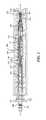
- FIG. 3is a side, cross-sectional view of a core assembly of the medical device delivery system shown in FIG. 2 , according to some embodiments.
- FIG. 4is an enlarged side, cross-sectional view of the delivery system shown in FIG. 2 .
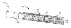
- FIG. 5Ais an enlarged perspective view of a coupling unit having couplers in accordance with some embodiments.
- FIG. 5Bis an enlarged perspective view of the coupling unit of FIG. 5A with an overlying stent.
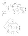
- FIGS. 6A-6Care side, end, and perspective views, respectively, of an individual coupler of the coupling unit of FIGS. 5A and 5B .
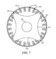
- FIG. 7is a schematic cross-sectional view of a coupler and the stent of FIG. 5B .
- Conventional stent couplersinclude soft “pads” that rely on friction fit to secure a stent (such as a braided, knit or woven stent) against an inner wall of a catheter.
- a stentsuch as a braided, knit or woven stent
- Such friction-fit padsmay require several different pad diameters to accommodate different stent wire size mixes. That is, within a given catheter size, the internal diameter of the compressed (braided, knit or woven) stent contained in the catheter will vary based on the sizes (diameters) of the wires, and possibly other parameters of the stent corresponding to different deployed sizes or target vessel sizes. This can require using different pad diameters to accommodate different stent sizes within a desired range (e.g.
- Embodiments of the present technologycan allow a single size coupler to be used with a relatively broad range of stent inner diameters within a given catheter size (e.g. a 0.027′′, 0.021′′, or 0.017′′ inner diameter catheter).
- a couplercomprising a rigid plate that has a plurality of projections separated by recesses can be used to secure a range of different stent sizes within a given catheter.
- FIGS. 1-7Specific details of several embodiments of the present technology are described herein with reference to FIGS. 1-7 . Although many of the embodiments are described with respect to devices, systems, and methods for delivery of stents and other medical devices, other applications and other embodiments in addition to those described herein are within the scope of the present technology. It should be noted that other embodiments in addition to those disclosed herein are within the scope of the present technology. Further, embodiments of the present technology can have different configurations, components, and/or procedures than those shown or described herein. Moreover, embodiments of the present technology can have configurations, components, and/or procedures in addition to those shown or described herein and that these and other embodiments may not have several of the configurations, components, and/or procedures shown or described herein without deviating from the present technology.
- distal and proximaldefine a position or direction with respect to a clinician or a clinician's control device (e.g., a handle of a delivery catheter).
- a clinician's control devicee.g., a handle of a delivery catheter.
- distal and distalrefer to a position distant from or in a direction away from a clinician or a clinician's control device along the length of device.
- proximal and proximallyrefer to a position near or in a direction toward a clinician or a clinician's control device along the length of device.
- the headings provided hereinare for convenience only and should not be construed as limiting the subject matter disclosed.
- FIGS. 1-7depict embodiments of medical device delivery systems that may be used to deliver and/or deploy a medical device, such as but not limited to a stent, into a hollow anatomical structure such as a blood vessel.
- the stentcan comprise a braided stent or other form of stent such as a woven stent, knit stent, laser-cut stent, roll-up stent, etc.
- the stentcan optionally be configured to act as a “flow diverter” device for treatment of aneurysms, such as those found in blood vessels including arteries in the brain or within the cranium, or in other locations in the body such as peripheral arteries.
- the stentcan optionally be similar to any of the versions or sizes of the PIPELINETM Embolization Device marketed by Medtronic Neurovascular of Irvine, Calif. USA.
- the stentcan alternatively comprise any suitable tubular medical device and/or other features, as described herein.
- FIG. 1is a schematic illustration of a medical device delivery system 100 configured in accordance with an embodiment of the present technology.
- the system 100can comprise an elongate tube or catheter 101 which slidably receives a core member 103 configured to carry a stent 105 through the catheter 101 .
- the depicted catheter 101has a proximal region 107 and an opposing distal region 109 which can be positioned at a treatment site within a patient, an internal lumen 111 extending from the proximal region 107 to the distal region 109 , and an inner surface 113 defining the lumen 111 .
- the catheter 101has a distal opening 115 through which the core member 103 may be advanced beyond the distal region 109 to expand or deploy the stent 105 within the blood vessel 116 .
- the proximal region 107may include a catheter hub (not shown).
- the catheter 101can define a generally longitudinal dimension extending between the proximal region 107 and the distal region 109 . When the delivery system 100 is in use, the longitudinal dimension need not be straight along some or any of its length.
- the core member 103is configured to extend generally longitudinally through the lumen 111 of the catheter 101 .
- the core member 103can generally comprise any member(s) with sufficient flexibility and column strength to move the stent 105 or other medical device through the catheter 101 .
- the core member 103can therefore comprise a wire, tube (e.g., hypotube), braid, coil, or other suitable member(s), or a combination of wire(s), tube(s), braid(s), coil(s), etc.
- the system 100can also include a coupling unit 117 (e.g., a device interface) configured to releasably retain the medical device or stent 105 with respect to the core member 103 .
- the coupling unit 117is configured to underlie and engage an inner wall of the stent 105 .
- the coupling unit 117cooperates with the overlying inner surface 113 of the catheter 101 to grip the stent 105 such that the coupling unit 117 can move the stent 105 along and within the catheter 101 , e.g., distal and/or proximal movement of the core member 103 relative to the catheter 101 results in a corresponding distal and/or proximal movement of the stent 105 within the catheter lumen 111 .
- the coupling unit 117can, in some embodiments, be configured to rotate about the core member 103 .
- the coupling unit 117can comprise a proximal restraint 119 and a distal restraint 121 .
- the proximal and distal restraints 119 , 121can be fixed to the core member 103 to prevent or limit proximal or distal movement of the coupling unit 117 along the longitudinal dimension of the core member 103 .
- One or both of the proximal and distal restraints 119 , 121can have an outside diameter or other radially outermost dimension that is smaller than the outside diameter or other radially outermost dimension of the coupling unit 117 such that one or both of the restraints 119 , 121 do not contact the inner surface of the stent 105 .
- the coupling unit 117can also include one or more couplers 123 a - c (e.g., stent engagement members) disposed about the core member 103 and between the proximal and distal restraints 119 , 121 and spacer(s) 125 a - d .
- couplers 123 a - ce.g., stent engagement members
- the couplers 123 a - care spaced apart from each other by spacers 125 b - c , the coupler 123 a is spaced apart from the proximal restraint 119 by spacer 125 a , and the coupler 123 c is spaced apart from the distal restraint by spacer 125 d (which can be omitted in some embodiments of the coupling unit 117 ).
- One, some or all of the couplers 123 a - ccan be a rigid plate with a central aperture configured to receive the core member 103 therethrough.
- the couplers 123 a - care configured to mechanically engage the stent 105 such that the couplers 123 a - c retain the stent 105 from moving longitudinally with respect to the core member 103 .
- the spacers 125 a - dcan each be a substantially cylindrical body with an aperture configured to receive the core member 103 therethrough.
- One or all of the spacers 125 a - dcan have an outside diameter or other radially outermost dimension that is smaller than the outside diameter or other radially outermost dimension of the couplers 123 a - c so the spacers 125 a - d do not contact the inner surface of the stent 105 .
- the number of couplers and spacerscan vary.
- the coupling unit 117includes only a single coupler without any spacers.
- the number of couplerscan vary, for example two, three, four, five, six, or more couplers separated by spacers.
- the stent 105can be moved distally or proximally within the catheter 101 via the core member 103 and the coupling unit 117 .
- the core member 103is moved distally while the catheter 101 is held stationary or the core member 103 is held stationary while the catheter 101 is withdrawn proximally.
- the proximal restraint 119bears against the proximal-most spacer 125 a and causes the spacers 125 a - d and the couplers 123 a - c to be advanced distally.
- the mechanical engagement between the couplers 123 a - c and the stent 105causes the stent 105 to move distally with the couplers 123 a - c to deploy the stent 105 out of the distal region 109 of the catheter 101 .
- the relative movement between the core member 103 and the catheter 101is reversed compared moving the stent 105 out of the catheter such that the proximal region of the distal restraint 121 bears against the distal region of the distal-most spacer 125 d and thereby causes the spacers 125 a - d and the couplers 123 a - c to be retracted relative to the catheter 101 .
- the mechanical engagement between the couplers 123 a - c and the stent 105accordingly holds the stent 105 with respect to the core member 103 such that proximal movement of the stent 105 relative to the catheter 101 enables re-sheathing of the stent 105 back into the distal region 109 of the catheter 101 .
- Thisis useful when the stent 105 has been partially deployed and a portion of the stent remains disposed between at least one of the couplers 123 a - c (e.g.
- the proximal-most coupler 123 aand the inner surface 113 of the catheter 101 because the stent 105 can be withdrawn back into the distal opening 115 of the catheter 101 by moving the core member 103 proximally relative to the catheter 101 (and/or moving the catheter 101 distally relative to the core member 103 ). Re-sheathing in this manner remains possible until the couplers 123 a - c and/or catheter 101 have been moved to a point where the proximal-most coupler 123 a is beyond the distal opening 115 of the catheter 101 and the stent 105 is released from between the member 123 a and the catheter 101 .
- the couplers 123 a - c and the spacers 125 a - dcan be fixed to the core member 103 so as to be immovable relative to the core member 103 , either in a longitudinal/sliding manner or a radial/rotational manner.
- the spacers 125 a - d and/or the couplers 123 a - ccan be coupled to (e.g., mounted on) the core member 103 so that the spacers 125 a - d and/or the couplers 123 a - c can rotate about the longitudinal axis of the core member 103 , and/or move or slide longitudinally along the core member 103 .
- the spacers 125 a - d and/or the couplers 123 a - ccan each have an inner lumen or aperture that receives the core member 103 therein such that the spacers 125 a - d and/or the couplers 123 a - c can slide and/or rotate relative to the core member 103 .
- the proximal and distal restraints 119 , 121can be spaced apart along the core member 103 by a longitudinal distance that is slightly greater than the combined length of the spacers 125 a - d and the couplers 123 a - c , so as to leave one or more longitudinal gaps between the proximal-most and distal-most spacers 125 a , 125 d , respectively, and the proximal and distal restraints 119 , 121 .
- the longitudinal gap(s)allow the spacers 125 a - d and the couplers 123 a - c to slide longitudinally along the core member 103 between the restraints 119 , 121 .
- the longitudinal range of motion of the spacers 125 a - d and the couplers 123 a - c between the restraints 119 , 121is approximately equal to the total combined length of the longitudinal gap(s).
- the coupling unit 117can include radial gaps between the outer surface of the core member 103 and the inner surface of the spacers 125 a - d and the couplers 123 a - c .
- Such radial gapscan be formed when the spacers 125 a - d and/or the couplers 123 a - c are constructed with holes that are somewhat larger than the outer diameter of the corresponding portion of the core member 103 .
- the radial gapsallow the spacers 125 a - d and/or the couplers 123 a - c to rotate about the longitudinal axis of the core member 103 between the restraints 119 , 121 .
- the presence of longitudinal gaps of at least a minimal size on either side of the spacers 125 a - d and the couplers 123 a - ccan also facilitate the rotatability of the spacers 125 a - d and the couplers 123 a - c.
- FIGS. 2-4illustrate another embodiment of a medical device delivery system configured in accordance with an embodiment of the present technology.
- the depicted medical device delivery system 200can comprise an elongate tube or catheter 210 which slidably receives a core assembly 240 configured to carry the stent 201 through the catheter 210 .
- FIG. 3illustrates the core assembly 240 without depicting the catheter 210 and blood vessel 202 for clarity.
- the depicted catheter 210see FIGS.
- the catheter 210has a proximal region 212 and an opposing distal region 214 which can be positioned at a treatment site within a patient, an internal lumen 216 extending from the proximal region 212 to the distal region 214 , and an inner surface 218 facing the lumen 216 .
- the catheter 210has a distal opening (not shown) through which the core assembly 240 may be advanced beyond the distal region 214 to expand or deploy the stent 201 within the blood vessel 202 .
- the proximal region 212may include a catheter hub 222 .
- the catheter 210can define a generally longitudinal dimension A-A extending between the proximal region 212 and the distal region 214 . When the delivery system 200 is in use, the longitudinal dimension need not be straight along some or any of its length.
- the catheter 101 / 210can optionally comprise a microcatheter.
- the catheter 101 / 210can optionally comprise any of the various lengths of the MARKSMANTM catheter available from Medtronic Neurovascular of Irvine, Calif. USA.
- the catheter 101 / 210can optionally comprise a microcatheter having an inner diameter of about 0.030 inches or less, and/or an outer diameter of 3 French or less near the distal region 109 / 214 .
- the catheter 101 / 210can comprise a microcatheter which is configured to percutaneously access the internal carotid artery, or another location within the neurovasculature distal of the internal carotid artery, with its distal opening 113 .
- the core assembly 240can comprise a core member 260 configured to extend generally longitudinally through the lumen 216 of the catheter 210 .
- the core member 260can have a proximal region or section 262 and a terminal or distal region 264 , which can optionally include a tip coil 265 .
- the core member 260can also comprise an intermediate portion 266 located between the proximal region 262 and the distal region 264 , which intermediate portion is the portion of the core member 260 onto or over which the stent 201 is positioned or fitted or extends when the core assembly 240 is in the pre-deployment configuration as shown in FIGS. 2-4 .
- the core member 260can generally comprise any member(s) with sufficient flexibility and column strength to move the stent 201 or other medical device through the catheter 210 .
- the core member 260can therefore comprise a wire, tube (e.g., hypotube), braid, coil, or other suitable member(s), or a combination of wire(s), tube(s), braid(s), coil(s), etc.
- 2-4is of multi-member construction, comprising a proximal wire 268 , a tube 270 (e.g., a hypotube) connected at its proximal region to a distal region of the proximal wire 268 , and a distal wire 272 connected at its proximal region to a distal region of the tube 270 .
- An outer layer 274which can comprise a layer of lubricious material such as PTFE (polytetrafluoroethylene or TEFLONTM) or other lubricious polymers, can cover some or all of the tube 270 and/or proximal wire 268 .
- the proximal and/or distal wires 268 , 272may taper or vary in diameter along some or all of their lengths.
- the proximal wire 268may include one or more fluorosafe markers 276 , and such marker(s) can be located on a portion of the wire 268 that is not covered by the outer layer 274 (e.g., proximal of the outer layer 274 ). This portion of the wire 268 marked by the marker(s) 276 , and/or proximal of any outer layer 274 , can comprise a bare metal outer surface.
- the core assembly 240can further comprise a proximal coupling unit 282 and/or a distal coupling unit 290 that can interconnect the medical device or stent 201 with the core member 260 .
- the proximal coupling unit 282can comprise one or more couplers 123 a - c that are configured to underlie the stent 201 and engage an inner wall of the stent.
- the proximal coupling unit 282cooperates with the overlying inner surface 218 of the catheter 210 to grip the stent 201 such that the proximal coupling unit 282 can move the stent 201 along and within the catheter 210 , e.g., as the user pushes the core member 260 distally and/or pulls the core member proximally relative to the catheter 210 , resulting in a corresponding distal and/or proximal movement of the stent 201 within the catheter lumen 216 .
- the proximal coupling unit 282can, in some embodiments, be similar to any of the versions or embodiments of the coupling unit 117 described above with respect to FIG. 1 .
- the proximal coupling unit 282can include proximal and distal restraints 119 , 121 that are fixed to the core member 260 (e.g., to the distal wire 272 thereof in the depicted embodiment) so as to be immovable relative to the core member 260 , either in a longitudinal/sliding manner or a radial/rotational manner.
- the proximal coupling unit 282can also include a plurality of couplers 123 a - c separated by spacers 125 a - d .
- the couplers 123 a - c and spacers 125 a - dcan be coupled to (e.g., mounted on) the core member 260 so that the proximal coupling unit 282 can rotate about the longitudinal axis A-A of the core member 260 (e.g., of the distal wire 272 ), and/or move or slide longitudinally along the core member.
- One or both of the proximal and distal restraints 119 , 121can have an outside diameter or other radially outermost dimension that is smaller than the outside diameter or other radially outermost dimension of the proximal coupling unit 282 , so that one or both of the restraints 119 , 121 will tend not to contact the inner surface of the stent 201 during operation of the core assembly 240 .
- the stent 201can be moved distally or proximally within the catheter 210 via the proximal coupling unit 282 and in some embodiments the stent 201 can be resheathed via the proximal coupling unit 282 after partial deployment from the distal opening of the catheter 210 , in a manner similar to that described above with respect to the coupling unit 117 in FIG. 1 .
- the proximal edge of the proximal coupling unit 282can be positioned just distal of the proximal edge of the stent 201 when in the delivery configuration shown in FIGS. 2-4 .
- thisenables the stent 201 to be re-sheathed when as little as a few millimeters of the stent remains in the catheter 210 . Therefore, with stents 201 of typical length, resheathability of 75% or more can be provided (i.e. the stent 201 can be re-sheathed when 75% or more of it has been deployed).
- the distal coupling unit 290can comprise a distal engagement member 292 that can take the form of, for example, a distal device cover or distal stent cover (generically, a “distal cover”).
- the distal cover 292can be configured to reduce friction between the medical device or stent 201 (e.g., the distal portion or distal region thereof) and the inner surface 218 of the catheter 210 .
- the distal cover 292can be configured as a lubricious, flexible structure having a free first end or section 292 a that can extend over at least a portion of the stent 201 and/or intermediate portion 266 of the core member 260 , and a fixed second end or section 292 b that can be coupled (directly or indirectly) to the core member 260 .
- the distal cover 292can have a first or delivery position, configuration, or orientation in which the distal cover can extend proximally relative to the distal tip 264 , or proximally from the second section 292 b or its (direct or indirect) attachment to the core member 260 , and at least partially surround or cover a distal portion of the stent 201 .
- the distal cover 292can be movable from the first or delivery orientation to a second or resheathing position, configuration, or orientation (not shown) in which the distal cover can be everted such that the first end 292 a of the distal cover is positioned distally relative to the second end 292 b of the distal cover 292 to enable the resheathing of the core assembly 240 , either with the stent 201 carried thereby, or without the stent.
- the distal cover 292can comprise one or more flexible, generally longitudinally extending strips, wings, or elongate portions that are coupled to or integrally formed with the second end 292 b .
- the distal cover 292can be manufactured or otherwise cut from a tube of the material selected for the distal cover or from multiple radial portions of such a tube.
- the first section 292 amay be formed as multiple longitudinal strips cut from the tube, and the second section 292 b may be an uncut (or similarly cut) length of the tube.
- the second section 292 b and the proximally extending strips of the first section 292 amay form a single, integral device or structure.
- the distal cover 292comprises only one, or no more than two strips, wings, or elongate portions.
- the distal cover 292may comprise a tube or a longitudinally slit tube
- the first section 292 acan include two or more semi-cylindrical or partially cylindrical strips or tube portions separated by a corresponding number of generally parallel, longitudinally oriented cuts or separations formed or otherwise positioned in the sidewall of the tube. Therefore, when in the pre-expansion state, as shown in FIGS. 2-4 , the first section 292 a may generally have the shape of a longitudinally split or longitudinally slotted tube extending or interposed radially between the outer surface of the stent or device 200 and the inner surface 218 of the catheter 210 .
- the strips, wings, or elongate portions of the first section 292 amay collectively span substantially the entire circumference of the outer surface of the stent 201 (e.g., where the cuts between the strips are splits of substantially zero width), or be sized somewhat less than the entire circumference (e.g., where the cuts between the strips are slots having a nonzero width).
- the width of the strips, wings, or elongate portions of the first section 292 acan be between about 0.5 mm and about 4 mm. The width can be about 0.5 mm to about 1.5 mm. In accordance with some embodiments, the width can be about 1 mm.
- the strips, wings, or elongate portions of the first section 292 acan also extend longitudinally over at least a portion of the distal portion of the stent 201 .
- the first section 292 acan extend between about 1 mm and about 3 mm, or between about 1.5 mm and about 2.5 mm, or about 2 mm, over the distal portion of the stent.
- the first section 292 a and the second section 292 bcan define a total length of the distal cover 292 .
- the total lengthcan be between about 4 mm and about 10 mm.
- the total lengthcan also be between about 5.5 mm and about 8.5 mm. In some embodiments, the total length can be about 7 mm.
- the strips of the first section 292 amay be of substantially uniform size.
- the first section 292 acan comprise two strips spanning approximately 180 degrees each, three strips spanning approximately 120 degrees each, four strips spanning approximately 90 degrees each, or otherwise be divided to collectively cover all or part of the circumference of the stent, etc.
- the stripsmay differ in angular sizing and coverage area without departing from the scope of the disclosure.
- only two strips or tube portionsare employed in the first section 292 a .
- the use of only two stripscan facilitate radial expansion, distal movement and/or fold-over or everting of the first section 292 a , as discussed herein, while minimizing the number of free or uncontained strips in the blood vessel lumen and any potential for injuring the vessel by virtue of contact between a strip and the vessel wall.
- the distal cover 292can be manufactured using a lubricious and/or hydrophilic material such as PTFE or Teflon®, but may be made from other suitable lubricious materials or lubricious polymers.
- the distal covercan also comprise a radiopaque material which can be blended into the main material (e.g., PTFE) to impart radiopacity.
- the distal cover 292can have a thickness of between about 0.0005′′ and about 0.003′′. In some embodiments, the distal cover can be one or more strips of PTFE having a thickness of about 0.001′′.
- the distal cover 292(e.g., the second end 292 b thereof) can be fixed to the core member 260 (e.g., to the distal wire 272 or distal tip 264 thereof) so as to be immovable relative to the core member 260 , either in a longitudinal/sliding manner or a radial/rotational manner.
- the core member 260e.g., to the distal wire 272 or distal tip 264 thereof
- the distal cover 292(e.g., the second end 292 b thereof) can be coupled to (e.g., mounted on) the core member 260 so that the distal cover 292 can rotate about the longitudinal axis A-A of the core member 260 (e.g., of the distal wire 272 ), and/or move or slide longitudinally along the core member.
- the second end 292 bcan have an inner lumen that receives the core member 260 therein such that the distal cover 292 can slide and/or rotate relative to the core member 260 .
- the distal coupling unit 290can further comprise a proximal restraint 294 that is fixed to the core member 260 and located proximal of the (second end 292 b of the) distal cover 292 , and/or a distal restraint 296 that is fixed to the core member 260 and located distal of the (second end 292 b of the) distal cover 292 .
- the proximal and distal restraints 294 , 296can be spaced apart along the core member 260 by a longitudinal distance that is slightly greater than the length of the second end 292 b , so as to leave one or more longitudinal gaps 297 between the second end 292 b and one or both of the proximal and distal restraints 294 , 296 , depending on the position of the second end 292 b between the restraints.
- the longitudinal gap(s) 297allow the second end 292 b and/or distal cover 292 to slide longitudinally along the core member 260 between the restraints 294 , 296 .
- the longitudinal range of motion of the second end 292 b and/or distal cover 292 between the restraints 294 , 296is approximately equal to the total length of the longitudinal gap(s) 297 .
- the distal coupling unit 290can comprise a radial gap 298 between the outer surface of the core member 260 (e.g., of the distal wire 272 ) and the inner surface of the second end 292 b .
- a radial gap 298can be formed when the second end 292 b is constructed with an inner luminal diameter that is somewhat larger than the outer diameter of the corresponding portion of the core member 260 .
- the radial gap 298allows the distal cover 292 and/or second end 292 b to rotate about the longitudinal axis A-A of the core member 260 between the restraints 294 , 296 .
- the presence of longitudinal gaps 297 of at least a minimal size on either side of the second end 292 bcan also facilitate the rotatability of the distal cover.
- One or both of the proximal and distal restraints 294 , 296can have an outside diameter or other radially outermost dimension that is smaller than the (e.g., pre-deployment) outside diameter or other radially outermost dimension of the distal cover 292 , so that one or both of the restraints 294 , 296 will tend not to bear against or contact the inner surface 218 of the catheter 210 during operation of the core assembly 240 .
- the second end 292 b of the distal cover 292includes an internal hoop 292 c which can comprise a (metallic or polymeric) coil as depicted, or other generally rigid, tubular, or cylindrical internal member such as a short segment of relatively stiff polymeric or metallic tubing.
- the internal hoop 292 ccan be contained in an annular enclosure or loop(s) formed by the second end 292 b , or otherwise attached to or integrated into the second end 292 b in a manner that tends to maintain an inside diameter of the distal cover 292 in the second end 292 b that is larger than the outside diameter of the adjacent portion of the core member 260 (or the wire 272 thereof).
- the hoop 292 ccan help maintain the presence of the radial gap 298 between the inside diameter of the second end 292 b and the outside diameter of the core member 260 or distal wire 272 .
- the annular enclosure or loop(s) of the second end 292 bcan be formed by wrapping a portion of a sheet or tube of the distal cover material (e.g., PTFE) around the sidewall and through the lumen of the hoop 292 c and adhering, gluing or heat bonding an end of the wrapped portion of the sheet or tube to the adjacent, proximally extending portion of the sheet or tube.
- the distal cover materialcomprises PTFE
- unsintered PTFEcan be used to enable bonding the two portions of the material together with heat and pressure, which is not typically possible with “ordinary” or sintered PTFE.
- the distal cover 292can generally cover and protect the distal region 304 of the stent 201 as the stent 201 is moved distally within the catheter 110 .
- the distal cover 292may serve as a bearing or buffer layer that, for example, inhibits filament ends of the distal region 304 of the stent 201 (where the stent 201 comprises a braided stent) from contacting the inner surface 118 of the catheter 110 , which could damage the stent 201 and/or catheter 110 , or otherwise compromise the structural integrity of the stent 201 .
- the distal cover 292may be made of a lubricious material, the distal cover 292 may exhibit a low coefficient of friction that allows the distal region 304 of the stent 201 to slide axially within the catheter 110 with relative ease.
- the coefficient of friction between the distal cover and the inner surface of the cathetercan be between about 0.02 and about 0.4.
- the coefficient of frictioncan be about 0.04.
- Such embodimentscan advantageously improve the ability of the core assembly to pass through the catheter, especially in tortuous vasculature.
- the distal cover 292can at least partially extend or be interposed radially between the distal portion of the stent 201 and the inner surface 218 of the catheter 210 in the first position, configuration, or orientation.
- the first section 292 a of the distal cover 292can extend from the second section 292 b in a proximal direction to a point where the first section is interposed between the distal portion of the stent 201 and the inner surface 218 of the catheter 210 .
- the first section of the distal covercan take on a “proximally oriented” position or configuration.
- distal cover 292may be used in the core assembly 240 and/or distal coupling unit 290 to cover or otherwise interface with the distal region 304 of the stent 201 .
- a protective coil or other sleeve having a longitudinally oriented, proximally open lumenmay be employed.
- the distal coupling unit 290can omit the distal cover 292 , or the distal cover can be replaced with a component similar to the proximal coupling unit 282 .
- distal cover 292it can be connected to the distal tip coil 265 (e.g., by being wrapped around and enclosing some or all of the winds of the coil 265 ) or being adhered to or coupled to the outer surface of the coil by an adhesive or a surrounding shrink tube.
- the distal cover 292can be coupled (directly or indirectly) to other portions of the core assembly 240 , such as the distal wire 272 .
- the stent 201can be rotatable with respect to the core member 260 about the longitudinal axis A-A thereof, by virtue of the rotatable (connections of the) proximal coupling unit 282 and distal cover 292 .
- the stent 201 , proximal coupling unit 282 and distal cover 292can rotate together in this manner about the core member.
- the core assembly 240can be advanced more easily through tortuous vessels as the tendency of the vessels to twist the stent and/or core assembly is negated by the rotation of the stent, proximal engagement member and distal cover about the core member.
- the required push force or delivery forceis reduced, as the user's input push force is not diverted into torsion of the stent and/or core member.
- the tendency of a twisted stent and/or core member to untwist suddenly or “whip” upon exiting tortuosity or deployment of the stent, and the tendency of a twisted stent to resist expansion upon deployment,are also reduced or eliminated.
- the usercan “steer” the core assembly 240 via the tip coil 265 , particularly if the coil 265 is bent at an angle in its unstressed configuration.
- a coil tipcan be rotated about the axis A-A relative to the stent 201 , coupling unit 282 and/or distal cover 292 by rotating the distal region 264 of the core member 260 .
- the usercan point the coil tip in the desired direction of travel of the core assembly, and upon advancement of the core assembly the tip will guide the core assembly in the chosen direction.
- FIG. 5Ais an enlarged perspective view of a coupling unit 517 of a medical device delivery system 500 .
- FIG. 5Billustrates the coupling unit 517 with an overlying stent 505 .
- the coupling unit 517includes a plurality of couplers 523 a - c separated by a plurality of spacers 525 a - d .
- a proximal restraint 519is disposed proximally to the proximal-most spacer 525 a .
- the proximal restraint 519 and the coupling unit 517are disposed around the core member 503 .
- FIGS. 6A-6Care side, end, and perspective views, respectively, of a coupler 523 of the coupling unit 517 shown in FIGS. 5A and 5B .
- FIG. 7is a schematic cross-sectional view of the coupler 523 engaging the stent 505 .
- the depicted stent 505is braided (although other types of stent, as disclosed elsewhere herein may be used) and includes a mesh 563 forming a plurality of pores 565 which are separated by points where the wires of the braid cross or intersect.
- each of the couplers 523can have a plate-like configuration with first and second end faces 551 , 553 and a side surface 555 extending between the first and second end faces 551 , 553 .
- the first and second end faces 551 , 553can be oriented and maintained substantially orthogonal to a long axis of the core member 503 .
- Each couplerforms a plurality of radially-extending projections 557 separated by recesses 559 .
- the number of projectionscan vary, for example two, three, four, five, six, seven, or more projections separated by a corresponding number of recesses.
- the projections 557can include rounded edges and the recesses 559 can include rounded depressions. During use of the delivery system 500 , the rounded edges can reduce scraping of the projections 557 against the inner wall of an overlying catheter 567 , which reduces generation of particulates and damage to the catheter 567 .
- the recesses 559can be sized to accommodate the thickness of braid wire crossings such that each projection can extend at least partially into a pore 565 of the stent 505 between the adjacent wire crossings and the wire crossings surrounding the pore 565 can be at least partially received within the recesses 559 of the coupler.
- the projections and/or the recessescan assume other forms, for example with sharper or flatter peaks formed by the projections.
- the coupler 523can be manufactured by photochemical etching, laser cutting, molding, machining or other suitable processes.
- Each coupler 523includes an opening or central aperture 561 configured to receive the core member 503 therethrough.
- the opening of the aperture 561can be larger than the diameter of the core member 503 such that the couplers 523 can rotate about the long axis of the core member 503 .
- the couplers 523can be made to have a relatively thin and/or plate-like configuration. Such a configuration can facilitate the formation of projections 557 that are small enough to fit inside the pores 565 of the stent 505 . Accordingly, the couplers 523 may be characterized by a largest diameter D along the first and second end faces 551 , 553 , and a thickness T measured along the side surface 555 . In some embodiments, the diameter D is at least five times greater than the thickness T. In at least one embodiment, the thickness T is between approximately 25-100 microns, or 25-75 microns, for example, approximately 50 microns (approximately 0.002′′).
- the couplers 523can be made to be rigid (e.g., incompressible by the forces encountered in typical use of the delivery system).
- the rigidity of the couplers 523can be due to their material composition, their shape/construction, or both.
- the couplers 523are made of metal (e.g., stainless steel, Nitinol, etc.) or rigid polymers (e.g., polyimide), or both.
- metale.g., stainless steel, Nitinol, etc.
- rigid polymerse.g., polyimide
- the spacers 525can be substantially cylindrical bodies having a smaller outer diameter than a largest outer diameter of the couplers 523 .
- the spacers 525include a central aperture (not shown) sized and configured to allow the spacers 525 to be rotatably mounted over the core member 503 .
- the spacers 525can have end walls that are orthogonal to a long axis of the core member 503 . These orthogonal end walls can help preserve the orthogonal orientation of the couplers 523 relative to the core member 503 to prevent loss of engagement with stent 505 .
- the coupling unit 517can be configured to engage only a proximal portion (e.g., only a proximal half, only the proximal-most third, etc.) of the stent 505 . In other embodiments, coupling unit 517 can engage the stent 505 along substantially its entire length.
- the couplers 523can mechanically interlock with or engage the stent 505 such that each projection 557 is at least partially received within one of the pores 565 .
- the spacerscan be configured with a length such that the projections 557 of adjacent couplers 523 (e.g., coupler 523 a and adjacent coupler 523 b ) are spaced apart longitudinally by a distance that is equal to the “pore pitch” of the stent 505 (the distance between the centers of longitudinally adjacent pores 565 ) or, more typically, a whole-number multiple of the pore pitch of the stent 505 , when the stent is at the inner diameter of the catheter 567 .
- each projectioncan extend into and engage one of the pores 565 of the stent 505 .
- adjacent couplers 523can engage longitudinally adjacent pores 565 of the stent 505 ; in other embodiments adjacent couplers 523 engage pores 565 which are not longitudinally adjacent but are spaced apart longitudinally by one or more intervening pores. Therefore the first and second couplers 523 a and 523 b can be spaced apart from one another by a longitudinal distance corresponding to the pore pitch of the stent 505 , or by a longitudinal distance corresponding to a whole number multiple of the pore pitch.
- the interaction between the projections 557 and the pores 565can produce a mechanical interlock between stent coupler 523 and the pores 565 .
- Thisis in contrast to a conventional compressible pad that resiliently pushes against the stent as a whole, including the wire crossings.
- the mechanical interlock provided by the couplers 523secures the stent 505 without pressing against the wire crossings of the stent 505 .
- the couplers 523are configured to secure a range of different stent sizes within a given catheter size (e.g., within a 0.017′′, 0.021′′ or 0.027′′ catheter (inside diameter)).
- any of the disclosed embodiments of the coupling unit 517can be employed as the coupling unit of the delivery system 100 or of the delivery system 200 .
- any of the embodiments of the couplers 523can be employed as the coupler(s) of the delivery system 100 or of the delivery system 200
- any of the embodiments of the spacers 525can be employed as the spacer(s) of the delivery system 100 or of the delivery system 200 .
Landscapes
- Health & Medical Sciences (AREA)
- Engineering & Computer Science (AREA)
- Biomedical Technology (AREA)
- Life Sciences & Earth Sciences (AREA)
- General Health & Medical Sciences (AREA)
- Veterinary Medicine (AREA)
- Public Health (AREA)
- Heart & Thoracic Surgery (AREA)
- Vascular Medicine (AREA)
- Animal Behavior & Ethology (AREA)
- Transplantation (AREA)
- Oral & Maxillofacial Surgery (AREA)
- Cardiology (AREA)
- Surgery (AREA)
- Neurosurgery (AREA)
- Reproductive Health (AREA)
- Nuclear Medicine, Radiotherapy & Molecular Imaging (AREA)
- Medical Informatics (AREA)
- Molecular Biology (AREA)
- Media Introduction/Drainage Providing Device (AREA)
Abstract
Description
Walls of the vasculature, particularly arterial walls, may develop areas of pathological dilatation called aneurysms that often have thin, weak walls that are prone to rupturing. Aneurysms are generally caused by weakening of the vessel wall due to disease, injury, or a congenital abnormality. Aneurysms occur in different parts of the body, and the most common are abdominal aortic aneurysms and cerebral (e.g., brain) aneurysms in the neurovasculature. When the weakened wall of an aneurysm ruptures, it can result in death, especially if it is a cerebral aneurysm that ruptures.
Aneurysms are generally treated by excluding or at least partially isolating the weakened part of the vessel from the arterial circulation. For example, conventional aneurysm treatments include: (i) surgical clipping, where a metal clip is secured around the base of the aneurysm; (ii) packing the aneurysm with small, flexible wire coils (micro-coils); (iii) using embolic materials to “fill” an aneurysm; (iv) using detachable balloons or coils to occlude the parent vessel that supplies the aneurysm; and (v) intravascular stenting.
Intravascular stents are well known in the medical arts for the treatment of vascular stenoses or aneurysms. Stents are prostheses that expand radially or otherwise within a vessel or lumen to support the vessel from collapsing. Methods for delivering these intravascular stents are also well known.
Conventional methods of introducing a compressed stent into a vessel and positioning it within an area of stenosis or an aneurysm include percutaneously advancing a distal portion of a guiding catheter through the vascular system of a patient until the distal portion is proximate the stenosis or aneurysm. A second, inner catheter and a guidewire within the inner catheter are advanced through the distal region of the guiding catheter. The guidewire is then advanced out of the distal region of the guiding catheter into the vessel until the distal portion of the guidewire carrying the compressed stent is positioned at the point of the lesion within the vessel. The compressed stent is then released and expanded so that it supports the vessel at the point of the lesion.
The present technology is illustrated, for example, according to various aspects described below. Various examples of aspects of the present technology are described as numbered clauses (1, 2, 3, etc.) for convenience. These are provided as examples and do not limit the present technology. It is noted that any of the dependent clauses may be combined in any combination, and placed into a respective independent clause, e.g., Clause 1 or Clause 23. The other clauses can be presented in a similar manner.
1. A stent delivery system, comprising:
- a core member having a distal segment;
- a coupler positioned about the core member distal segment and rotatably coupled to the core member, the coupler comprising a rigid plate having a first end surface, a second end surface, and a side surface extending between the first and second end surfaces, the side surface comprising one or more projections separated by recesses; and
- a stent extending along the core member distal segment such that an inner surface of the stent is engaged by the one or more projections of the coupler.
2. The stent delivery system of Clause 1, wherein the projections comprise rounded edges.
3. The stent delivery system of Clause 1, wherein the one or more projections comprises three or more projections.
4. The stent delivery system of Clause 1, wherein a longest dimension of the first and second end surfaces is configured to fit within a 0.017″, 0.021″ or 0.027″ inner diameter catheter.
5. The stent delivery system of Clause 1, wherein a maximum length of the first and second end surfaces is at least 5 times greater than a length of the side surface, the maximum length of the first and second end surfaces being generally orthogonal to the length of the side surface.
6. The stent delivery system of Clause 1, wherein the rigid plate comprises at least one of a metal or a rigid polymer.
7. The stent delivery system of Clause 1, wherein the rigid plate side surface has a length of between about 25-100 microns.
8. The stent delivery system of Clause 1, wherein the rigid plate is a first rigid plate, the stent delivery system further comprising:
- a second rigid plate positioned about the core member distal segment and spaced apart from the first rigid plate; and
- a spacer positioned about the core member distal segment, the spacer positioned between the first rigid plate and the second rigid plate.
9. The stent delivery system of Clause 8, wherein the spacer comprises a cylindrical body having end walls orthogonal to a long axis of the core member.
10. The stent delivery system of Clause 8, wherein the first and second rigid plates are spaced apart from one another by a distance corresponding to a pore pitch of the stent.
11. The stent delivery system of Clause 1, wherein the first and second end surfaces are substantially orthogonal to a long axis of the core member.
12. The stent delivery system of Clause 1, wherein the projections interlock with the stent such that each projection is at least partially received within a pore of the stent.
13. A stent delivery system, comprising:
- a catheter having a lumen and an inner surface extending along the lumen;
- a core member, extending within the catheter lumen;
- a plate comprising:
- a first end surface, a second end surface, and a side surface extending between the first end surface and the second end surface; and
- an aperture extending through the first and second end surfaces, the core member extending through the aperture such that the plate can rotate about the core member; and
- a stent extending along the core member and over the plate, at least a portion of the stent being radially positioned between the plate side surface and the catheter inner surface.
14. The stent delivery system of Clause 13, wherein the plate side surface comprises a plurality of projections separated by recesses.
15. The stent delivery system of Clause 14, wherein the projections interlock with the stent such that each projection is at least partially received within a pore of the stent.
16. The stent delivery system of Clause 14, wherein the one or more projections comprises three or more projections.
17. The stent delivery system of Clause 13, wherein a maximum length of the first and second end surfaces is at least 5 times greater than a length of the side surface, the maximum length of the first and second end surfaces being generally orthogonal to the length of the side surface.
18. The stent delivery system of Clause 13, wherein the plate comprises at least one of a metal or a rigid polymer.
19. The stent delivery system of Clause 13, wherein the plate is a first plate, the stent delivery system further comprising:
- a second plate positioned about the core member and spaced apart from the first plate; and
- a spacer positioned about the core member and positioned between the first plate and the second plate.
20. The stent delivery system of Clause 19, wherein the spacer comprises a cylindrical body having end walls orthogonal to a long axis of the core member.
21. The stent delivery system of Clause 19, wherein the first and second plates are spaced apart from one another by a distance corresponding to a pore pitch of the stent.
22. A core assembly comprising:
- a core member;
- a first rigid plate around the core member;
- a second rigid plate around the core member and spaced apart from the first rigid plate; and
- a spacer around the core member, the spacer disposed between the first rigid plate and the second rigid plate.
23. The core member of Clause 22, wherein the first and second rigid plates each comprise:
- a first end surface;
- a second end surface opposite the first end surface;
- a side surface extending between the first and second end surfaces, the side surface comprising a plurality of projections separated by recesses; and
- an aperture extending through the first and second end surfaces, the aperture receiving the core member therethrough.
24. The core member of Clause 23, wherein the one or more projections comprises three or more projections.
25. The core member of Clause 23, wherein a maximum length of the first and second end surfaces is at least 5 times greater than a length of the side surface, the maximum length of the first and second end surfaces being generally orthogonal to the length of the side surface.
26. The core member of Clause 23, wherein the first and second end surfaces are substantially orthogonal to a long axis of the core member.
27. The core member of Clause 22, wherein the first and second rigid plates comprise at least one of a metal or a rigid polymer.
28. The core member of Clause 22, wherein the first and second rigid plates each have a thickness of between about 25-100 microns.
29. The core member of Clause 22, wherein the spacer comprises a cylindrical body having end walls orthogonal to a long axis of the core member.
30. A rigid plate for engaging a stent, the plate comprising:
- first and second end surfaces;
- a side surface extending between the first and second end surfaces, the side surface including a plurality of projections separated by recesses; and
- a central opening extending through the rigid plate between the first and second end surfaces.
31. The rigid plate of Clause 30, wherein the projections comprise rounded edges.
32. The rigid plate of Clause 30, wherein the one or more projections comprises three or more projections.
33. The rigid plate of Clause 30, wherein a longest dimension of the first and second end surfaces is configured to fit within a 0.017″, 0.021″ or 0.027″ inner diameter catheter.
34. The rigid plate of Clause 30, wherein a maximum length of the first and second end surfaces is at least 5 times greater than a length of the side surface, the maximum length of the first and second end surfaces being generally orthogonal to the length of the side surface.
35. The rigid plate of Clause 30, wherein the rigid plate comprises at least one of a metal or a rigid polymer.
36. The rigid plate of Clause 30, wherein the side surface has a length of between about 25-100 microns.
37. The rigid plate of Clause 30, wherein the first and second end surfaces are substantially orthogonal to a long axis of the central opening.
Additional features and advantages of the present technology will be set forth in the description below, and in part will be apparent from the description, or may be learned by practice of the subject technology. The advantages of the present technology will be realized and attained by the structure particularly pointed out in the written description and claims hereof as well as the appended drawings.
It is to be understood that both the foregoing general description and the following detailed description are exemplary and explanatory and are intended to provide further explanation of the present technology as claimed.
Many aspects of the present disclosure can be better understood with reference to the following drawings. The components in the drawings are not necessarily to scale. Instead, emphasis is placed on illustrating clearly the principles of the present technology. For ease of reference, throughout this disclosure identical reference numbers may be used to identify identical or at least generally similar or analogous components or features.
Conventional stent couplers include soft “pads” that rely on friction fit to secure a stent (such as a braided, knit or woven stent) against an inner wall of a catheter. Such friction-fit pads may require several different pad diameters to accommodate different stent wire size mixes. That is, within a given catheter size, the internal diameter of the compressed (braided, knit or woven) stent contained in the catheter will vary based on the sizes (diameters) of the wires, and possibly other parameters of the stent corresponding to different deployed sizes or target vessel sizes. This can require using different pad diameters to accommodate different stent sizes within a desired range (e.g. about 3.5 to 5 millimeters in diameter), which necessitates manufacturing the pads of various diameters to very small size tolerances. Embodiments of the present technology can allow a single size coupler to be used with a relatively broad range of stent inner diameters within a given catheter size (e.g. a 0.027″, 0.021″, or 0.017″ inner diameter catheter). For example, a coupler comprising a rigid plate that has a plurality of projections separated by recesses can be used to secure a range of different stent sizes within a given catheter.
Specific details of several embodiments of the present technology are described herein with reference toFIGS. 1-7 . Although many of the embodiments are described with respect to devices, systems, and methods for delivery of stents and other medical devices, other applications and other embodiments in addition to those described herein are within the scope of the present technology. It should be noted that other embodiments in addition to those disclosed herein are within the scope of the present technology. Further, embodiments of the present technology can have different configurations, components, and/or procedures than those shown or described herein. Moreover, embodiments of the present technology can have configurations, components, and/or procedures in addition to those shown or described herein and that these and other embodiments may not have several of the configurations, components, and/or procedures shown or described herein without deviating from the present technology.
As used herein, the terms “distal” and “proximal” define a position or direction with respect to a clinician or a clinician's control device (e.g., a handle of a delivery catheter). For example, the terms, “distal” and “distally” refer to a position distant from or in a direction away from a clinician or a clinician's control device along the length of device. In a related example, the terms “proximal” and “proximally” refer to a position near or in a direction toward a clinician or a clinician's control device along the length of device. The headings provided herein are for convenience only and should not be construed as limiting the subject matter disclosed.
Selected Examples of Couplers for Medical Device Delivery Systems
Thecore member 103 is configured to extend generally longitudinally through thelumen 111 of thecatheter 101. Thecore member 103 can generally comprise any member(s) with sufficient flexibility and column strength to move thestent 105 or other medical device through thecatheter 101. Thecore member 103 can therefore comprise a wire, tube (e.g., hypotube), braid, coil, or other suitable member(s), or a combination of wire(s), tube(s), braid(s), coil(s), etc.
Thesystem 100 can also include a coupling unit117 (e.g., a device interface) configured to releasably retain the medical device orstent 105 with respect to thecore member 103. Thecoupling unit 117 is configured to underlie and engage an inner wall of thestent 105. In this manner, thecoupling unit 117 cooperates with the overlyinginner surface 113 of thecatheter 101 to grip thestent 105 such that thecoupling unit 117 can move thestent 105 along and within thecatheter 101, e.g., distal and/or proximal movement of thecore member 103 relative to thecatheter 101 results in a corresponding distal and/or proximal movement of thestent 105 within thecatheter lumen 111.
Thecoupling unit 117 can, in some embodiments, be configured to rotate about thecore member 103. In some such embodiments, thecoupling unit 117 can comprise aproximal restraint 119 and adistal restraint 121. The proximal anddistal restraints core member 103 to prevent or limit proximal or distal movement of thecoupling unit 117 along the longitudinal dimension of thecore member 103. One or both of the proximal anddistal restraints coupling unit 117 such that one or both of therestraints stent 105.
Thecoupling unit 117 can also include one or more couplers123a-c(e.g., stent engagement members) disposed about thecore member 103 and between the proximal anddistal restraints spacers 125b-c, thecoupler 123ais spaced apart from theproximal restraint 119 byspacer 125a, and thecoupler 123cis spaced apart from the distal restraint byspacer 125d(which can be omitted in some embodiments of the coupling unit117). One, some or all of the couplers123a-ccan be a rigid plate with a central aperture configured to receive thecore member 103 therethrough. The couplers123a-care configured to mechanically engage thestent 105 such that the couplers123a-cretain thestent 105 from moving longitudinally with respect to thecore member 103. The spacers125a-dcan each be a substantially cylindrical body with an aperture configured to receive thecore member 103 therethrough. One or all of the spacers125a-dcan have an outside diameter or other radially outermost dimension that is smaller than the outside diameter or other radially outermost dimension of the couplers123a-cso the spacers125a-ddo not contact the inner surface of thestent 105.
Although the embodiment illustrated inFIG. 1 includes three couplers123a-cand four spacers125a-d, the number of couplers and spacers can vary. In at least one embodiment, thecoupling unit 117 includes only a single coupler without any spacers. In other embodiments, the number of couplers can vary, for example two, three, four, five, six, or more couplers separated by spacers.
In operation, thestent 105 can be moved distally or proximally within thecatheter 101 via thecore member 103 and thecoupling unit 117. To move thestent 105 out of thecatheter 101, either thecore member 103 is moved distally while thecatheter 101 is held stationary or thecore member 103 is held stationary while thecatheter 101 is withdrawn proximally. When thecore member 103 is moved distally and thecatheter 101 is held stationary, theproximal restraint 119 bears against theproximal-most spacer 125aand causes the spacers125a-dand the couplers123a-cto be advanced distally. The mechanical engagement between the couplers123a-cand thestent 105 causes thestent 105 to move distally with the couplers123a-cto deploy thestent 105 out of thedistal region 109 of thecatheter 101. Conversely, to recapture or otherwise move thestent 105 into thecatheter 101, the relative movement between thecore member 103 and thecatheter 101 is reversed compared moving thestent 105 out of the catheter such that the proximal region of thedistal restraint 121 bears against the distal region of thedistal-most spacer 125dand thereby causes the spacers125a-dand the couplers123a-cto be retracted relative to thecatheter 101. The mechanical engagement between the couplers123a-cand thestent 105 accordingly holds thestent 105 with respect to thecore member 103 such that proximal movement of thestent 105 relative to thecatheter 101 enables re-sheathing of thestent 105 back into thedistal region 109 of thecatheter 101. This is useful when thestent 105 has been partially deployed and a portion of the stent remains disposed between at least one of the couplers123a-c(e.g. theproximal-most coupler 123a) and theinner surface 113 of thecatheter 101 because thestent 105 can be withdrawn back into thedistal opening 115 of thecatheter 101 by moving thecore member 103 proximally relative to the catheter101 (and/or moving thecatheter 101 distally relative to the core member103). Re-sheathing in this manner remains possible until the couplers123a-cand/orcatheter 101 have been moved to a point where theproximal-most coupler 123ais beyond thedistal opening 115 of thecatheter 101 and thestent 105 is released from between themember 123aand thecatheter 101.
The couplers123a-cand the spacers125a-dcan be fixed to thecore member 103 so as to be immovable relative to thecore member 103, either in a longitudinal/sliding manner or a radial/rotational manner. Alternatively, the spacers125a-dand/or the couplers123a-ccan be coupled to (e.g., mounted on) thecore member 103 so that the spacers125a-dand/or the couplers123a-ccan rotate about the longitudinal axis of thecore member 103, and/or move or slide longitudinally along thecore member 103. In such embodiments, the spacers125a-dand/or the couplers123a-ccan each have an inner lumen or aperture that receives thecore member 103 therein such that the spacers125a-dand/or the couplers123a-ccan slide and/or rotate relative to thecore member 103. Additionally in such embodiments, the proximal anddistal restraints core member 103 by a longitudinal distance that is slightly greater than the combined length of the spacers125a-dand the couplers123a-c, so as to leave one or more longitudinal gaps between the proximal-most anddistal-most spacers distal restraints core member 103 between therestraints restraints
Instead of or in addition to the longitudinal gap(s), thecoupling unit 117 can include radial gaps between the outer surface of thecore member 103 and the inner surface of the spacers125a-dand the couplers123a-c. Such radial gaps can be formed when the spacers125a-dand/or the couplers123a-care constructed with holes that are somewhat larger than the outer diameter of the corresponding portion of thecore member 103. When present, the radial gaps allow the spacers125a-dand/or the couplers123a-cto rotate about the longitudinal axis of thecore member 103 between therestraints
Thecatheter 101/210 can optionally comprise a microcatheter. For example, thecatheter 101/210 can optionally comprise any of the various lengths of the MARKSMAN™ catheter available from Medtronic Neurovascular of Irvine, Calif. USA. Thecatheter 101/210 can optionally comprise a microcatheter having an inner diameter of about 0.030 inches or less, and/or an outer diameter of 3 French or less near thedistal region 109/214. Instead of or in addition to these specifications, thecatheter 101/210 can comprise a microcatheter which is configured to percutaneously access the internal carotid artery, or another location within the neurovasculature distal of the internal carotid artery, with itsdistal opening 113.
Thecore assembly 240 can comprise acore member 260 configured to extend generally longitudinally through thelumen 216 of thecatheter 210. Thecore member 260 can have a proximal region orsection 262 and a terminal ordistal region 264, which can optionally include atip coil 265. Thecore member 260 can also comprise anintermediate portion 266 located between theproximal region 262 and thedistal region 264, which intermediate portion is the portion of thecore member 260 onto or over which thestent 201 is positioned or fitted or extends when thecore assembly 240 is in the pre-deployment configuration as shown inFIGS. 2-4 .
Thecore member 260 can generally comprise any member(s) with sufficient flexibility and column strength to move thestent 201 or other medical device through thecatheter 210. Thecore member 260 can therefore comprise a wire, tube (e.g., hypotube), braid, coil, or other suitable member(s), or a combination of wire(s), tube(s), braid(s), coil(s), etc. The embodiment of thecore member 260 depicted inFIGS. 2-4 is of multi-member construction, comprising aproximal wire 268, a tube270 (e.g., a hypotube) connected at its proximal region to a distal region of theproximal wire 268, and adistal wire 272 connected at its proximal region to a distal region of thetube 270. Anouter layer 274, which can comprise a layer of lubricious material such as PTFE (polytetrafluoroethylene or TEFLON™) or other lubricious polymers, can cover some or all of thetube 270 and/orproximal wire 268. The proximal and/ordistal wires proximal wire 268 may include one ormore fluorosafe markers 276, and such marker(s) can be located on a portion of thewire 268 that is not covered by the outer layer274 (e.g., proximal of the outer layer274). This portion of thewire 268 marked by the marker(s)276, and/or proximal of anyouter layer 274, can comprise a bare metal outer surface.
Thecore assembly 240 can further comprise aproximal coupling unit 282 and/or adistal coupling unit 290 that can interconnect the medical device orstent 201 with thecore member 260. Theproximal coupling unit 282 can comprise one or more couplers123a-cthat are configured to underlie thestent 201 and engage an inner wall of the stent. In this manner, theproximal coupling unit 282 cooperates with the overlyinginner surface 218 of thecatheter 210 to grip thestent 201 such that theproximal coupling unit 282 can move thestent 201 along and within thecatheter 210, e.g., as the user pushes thecore member 260 distally and/or pulls the core member proximally relative to thecatheter 210, resulting in a corresponding distal and/or proximal movement of thestent 201 within thecatheter lumen 216.
Theproximal coupling unit 282 can, in some embodiments, be similar to any of the versions or embodiments of thecoupling unit 117 described above with respect toFIG. 1 . For example, theproximal coupling unit 282 can include proximal anddistal restraints distal wire 272 thereof in the depicted embodiment) so as to be immovable relative to thecore member 260, either in a longitudinal/sliding manner or a radial/rotational manner. Theproximal coupling unit 282 can also include a plurality of couplers123a-cseparated by spacers125a-d. The couplers123a-cand spacers125a-dcan be coupled to (e.g., mounted on) thecore member 260 so that theproximal coupling unit 282 can rotate about the longitudinal axis A-A of the core member260 (e.g., of the distal wire272), and/or move or slide longitudinally along the core member. One or both of the proximal anddistal restraints proximal coupling unit 282, so that one or both of therestraints stent 201 during operation of thecore assembly 240.
In theproximal coupling unit 282 shown inFIGS. 2-4 , thestent 201 can be moved distally or proximally within thecatheter 210 via theproximal coupling unit 282 and in some embodiments thestent 201 can be resheathed via theproximal coupling unit 282 after partial deployment from the distal opening of thecatheter 210, in a manner similar to that described above with respect to thecoupling unit 117 inFIG. 1 .
Optionally, the proximal edge of theproximal coupling unit 282 can be positioned just distal of the proximal edge of thestent 201 when in the delivery configuration shown inFIGS. 2-4 . In some such embodiments, this enables thestent 201 to be re-sheathed when as little as a few millimeters of the stent remains in thecatheter 210. Therefore, withstents 201 of typical length, resheathability of 75% or more can be provided (i.e. thestent 201 can be re-sheathed when 75% or more of it has been deployed).
Thedistal coupling unit 290 can comprise adistal engagement member 292 that can take the form of, for example, a distal device cover or distal stent cover (generically, a “distal cover”). Thedistal cover 292 can be configured to reduce friction between the medical device or stent201 (e.g., the distal portion or distal region thereof) and theinner surface 218 of thecatheter 210. For example, thedistal cover 292 can be configured as a lubricious, flexible structure having a free first end orsection 292athat can extend over at least a portion of thestent 201 and/orintermediate portion 266 of thecore member 260, and a fixed second end orsection 292bthat can be coupled (directly or indirectly) to thecore member 260.
Thedistal cover 292 can have a first or delivery position, configuration, or orientation in which the distal cover can extend proximally relative to thedistal tip 264, or proximally from thesecond section 292bor its (direct or indirect) attachment to thecore member 260, and at least partially surround or cover a distal portion of thestent 201. Thedistal cover 292 can be movable from the first or delivery orientation to a second or resheathing position, configuration, or orientation (not shown) in which the distal cover can be everted such that thefirst end 292aof the distal cover is positioned distally relative to thesecond end 292bof thedistal cover 292 to enable the resheathing of thecore assembly 240, either with thestent 201 carried thereby, or without the stent.
Thedistal cover 292, particularly thefirst end 292athereof, can comprise one or more flexible, generally longitudinally extending strips, wings, or elongate portions that are coupled to or integrally formed with thesecond end 292b. Thedistal cover 292 can be manufactured or otherwise cut from a tube of the material selected for the distal cover or from multiple radial portions of such a tube. In such embodiments thefirst section 292amay be formed as multiple longitudinal strips cut from the tube, and thesecond section 292bmay be an uncut (or similarly cut) length of the tube. Accordingly, thesecond section 292band the proximally extending strips of thefirst section 292amay form a single, integral device or structure. In some embodiments, thedistal cover 292 comprises only one, or no more than two strips, wings, or elongate portions.
In some embodiments, thedistal cover 292 may comprise a tube or a longitudinally slit tube, and thefirst section 292acan include two or more semi-cylindrical or partially cylindrical strips or tube portions separated by a corresponding number of generally parallel, longitudinally oriented cuts or separations formed or otherwise positioned in the sidewall of the tube. Therefore, when in the pre-expansion state, as shown inFIGS. 2-4 , thefirst section 292amay generally have the shape of a longitudinally split or longitudinally slotted tube extending or interposed radially between the outer surface of the stent ordevice 200 and theinner surface 218 of thecatheter 210.
In various embodiments, the strips, wings, or elongate portions of thefirst section 292amay collectively span substantially the entire circumference of the outer surface of the stent201 (e.g., where the cuts between the strips are splits of substantially zero width), or be sized somewhat less than the entire circumference (e.g., where the cuts between the strips are slots having a nonzero width). In accordance with some embodiments, the width of the strips, wings, or elongate portions of thefirst section 292acan be between about 0.5 mm and about 4 mm. The width can be about 0.5 mm to about 1.5 mm. In accordance with some embodiments, the width can be about 1 mm.
The strips, wings, or elongate portions of thefirst section 292acan also extend longitudinally over at least a portion of the distal portion of thestent 201. In various embodiments, thefirst section 292acan extend between about 1 mm and about 3 mm, or between about 1.5 mm and about 2.5 mm, or about 2 mm, over the distal portion of the stent.
Thefirst section 292aand thesecond section 292bcan define a total length of thedistal cover 292. In some embodiments, the total length can be between about 4 mm and about 10 mm. The total length can also be between about 5.5 mm and about 8.5 mm. In some embodiments, the total length can be about 7 mm.
The strips of thefirst section 292amay be of substantially uniform size. For example, thefirst section 292acan comprise two strips spanning approximately 180 degrees each, three strips spanning approximately 120 degrees each, four strips spanning approximately 90 degrees each, or otherwise be divided to collectively cover all or part of the circumference of the stent, etc. Alternatively, the strips may differ in angular sizing and coverage area without departing from the scope of the disclosure. In one embodiment, only two strips or tube portions are employed in thefirst section 292a. The use of only two strips can facilitate radial expansion, distal movement and/or fold-over or everting of thefirst section 292a, as discussed herein, while minimizing the number of free or uncontained strips in the blood vessel lumen and any potential for injuring the vessel by virtue of contact between a strip and the vessel wall.
Thedistal cover 292 can be manufactured using a lubricious and/or hydrophilic material such as PTFE or Teflon®, but may be made from other suitable lubricious materials or lubricious polymers. The distal cover can also comprise a radiopaque material which can be blended into the main material (e.g., PTFE) to impart radiopacity. Thedistal cover 292 can have a thickness of between about 0.0005″ and about 0.003″. In some embodiments, the distal cover can be one or more strips of PTFE having a thickness of about 0.001″.
The distal cover292 (e.g., thesecond end 292bthereof) can be fixed to the core member260 (e.g., to thedistal wire 272 ordistal tip 264 thereof) so as to be immovable relative to thecore member 260, either in a longitudinal/sliding manner or a radial/rotational manner. Alternatively, as depicted inFIGS. 2-4 , the distal cover292 (e.g., thesecond end 292bthereof) can be coupled to (e.g., mounted on) thecore member 260 so that thedistal cover 292 can rotate about the longitudinal axis A-A of the core member260 (e.g., of the distal wire272), and/or move or slide longitudinally along the core member. In such embodiments, thesecond end 292bcan have an inner lumen that receives thecore member 260 therein such that thedistal cover 292 can slide and/or rotate relative to thecore member 260. Additionally in such embodiments, thedistal coupling unit 290 can further comprise aproximal restraint 294 that is fixed to thecore member 260 and located proximal of the (second end 292bof the)distal cover 292, and/or adistal restraint 296 that is fixed to thecore member 260 and located distal of the (second end 292bof the)distal cover 292. The proximal anddistal restraints core member 260 by a longitudinal distance that is slightly greater than the length of thesecond end 292b, so as to leave one or morelongitudinal gaps 297 between thesecond end 292band one or both of the proximal anddistal restraints second end 292bbetween the restraints. When present, the longitudinal gap(s)297 allow thesecond end 292band/ordistal cover 292 to slide longitudinally along thecore member 260 between therestraints second end 292band/ordistal cover 292 between therestraints
Instead of or in addition to the longitudinal gap(s)297, thedistal coupling unit 290 can comprise aradial gap 298 between the outer surface of the core member260 (e.g., of the distal wire272) and the inner surface of thesecond end 292b. Such aradial gap 298 can be formed when thesecond end 292bis constructed with an inner luminal diameter that is somewhat larger than the outer diameter of the corresponding portion of thecore member 260. When present, theradial gap 298 allows thedistal cover 292 and/orsecond end 292bto rotate about the longitudinal axis A-A of thecore member 260 between therestraints longitudinal gaps 297 of at least a minimal size on either side of thesecond end 292bcan also facilitate the rotatability of the distal cover.
One or both of the proximal anddistal restraints distal cover 292, so that one or both of therestraints inner surface 218 of thecatheter 210 during operation of thecore assembly 240.
In the embodiment depicted inFIGS. 2-4 , thesecond end 292bof thedistal cover 292 includes aninternal hoop 292cwhich can comprise a (metallic or polymeric) coil as depicted, or other generally rigid, tubular, or cylindrical internal member such as a short segment of relatively stiff polymeric or metallic tubing. Theinternal hoop 292ccan be contained in an annular enclosure or loop(s) formed by thesecond end 292b, or otherwise attached to or integrated into thesecond end 292bin a manner that tends to maintain an inside diameter of thedistal cover 292 in thesecond end 292bthat is larger than the outside diameter of the adjacent portion of the core member260 (or thewire 272 thereof). In other words, thehoop 292ccan help maintain the presence of theradial gap 298 between the inside diameter of thesecond end 292band the outside diameter of thecore member 260 ordistal wire 272.
The annular enclosure or loop(s) of thesecond end 292bcan be formed by wrapping a portion of a sheet or tube of the distal cover material (e.g., PTFE) around the sidewall and through the lumen of thehoop 292cand adhering, gluing or heat bonding an end of the wrapped portion of the sheet or tube to the adjacent, proximally extending portion of the sheet or tube. Thus are formed two layers that are adhered together on the proximal side of thehoop 292c. Where the distal cover material comprises PTFE, unsintered PTFE can be used to enable bonding the two portions of the material together with heat and pressure, which is not typically possible with “ordinary” or sintered PTFE.
In operation, thedistal cover 292, and in particular thefirst section 292a, can generally cover and protect thedistal region 304 of thestent 201 as thestent 201 is moved distally within the catheter110. Thedistal cover 292 may serve as a bearing or buffer layer that, for example, inhibits filament ends of thedistal region 304 of the stent201 (where thestent 201 comprises a braided stent) from contacting the inner surface118 of the catheter110, which could damage thestent 201 and/or catheter110, or otherwise compromise the structural integrity of thestent 201. Since thedistal cover 292 may be made of a lubricious material, thedistal cover 292 may exhibit a low coefficient of friction that allows thedistal region 304 of thestent 201 to slide axially within the catheter110 with relative ease. The coefficient of friction between the distal cover and the inner surface of the catheter can be between about 0.02 and about 0.4. For example, in embodiments in which the distal cover and the catheter are formed from PTFE, the coefficient of friction can be about 0.04. Such embodiments can advantageously improve the ability of the core assembly to pass through the catheter, especially in tortuous vasculature.
Further, as shown inFIGS. 2-4 , at least a portion of thedistal cover 292 can at least partially extend or be interposed radially between the distal portion of thestent 201 and theinner surface 218 of thecatheter 210 in the first position, configuration, or orientation. In the first orientation, thefirst section 292aof thedistal cover 292 can extend from thesecond section 292bin a proximal direction to a point where the first section is interposed between the distal portion of thestent 201 and theinner surface 218 of thecatheter 210. In this orientation, the first section of the distal cover can take on a “proximally oriented” position or configuration.
Structures other than the herein-described embodiments of thedistal cover 292 may be used in thecore assembly 240 and/ordistal coupling unit 290 to cover or otherwise interface with thedistal region 304 of thestent 201. For example, a protective coil or other sleeve having a longitudinally oriented, proximally open lumen may be employed. In other embodiments, thedistal coupling unit 290 can omit thedistal cover 292, or the distal cover can be replaced with a component similar to theproximal coupling unit 282. Where thedistal cover 292 is employed, it can be connected to the distal tip coil265 (e.g., by being wrapped around and enclosing some or all of the winds of the coil265) or being adhered to or coupled to the outer surface of the coil by an adhesive or a surrounding shrink tube. Thedistal cover 292 can be coupled (directly or indirectly) to other portions of thecore assembly 240, such as thedistal wire 272.
In embodiments of thecore assembly 240 that employ both a rotatableproximal coupling unit 282 and a rotatabledistal cover 292, thestent 201 can be rotatable with respect to thecore member 260 about the longitudinal axis A-A thereof, by virtue of the rotatable (connections of the)proximal coupling unit 282 anddistal cover 292. In such embodiments, thestent 201,proximal coupling unit 282 anddistal cover 292 can rotate together in this manner about the core member. When thestent 201 can rotate about thecore member 260, thecore assembly 240 can be advanced more easily through tortuous vessels as the tendency of the vessels to twist the stent and/or core assembly is negated by the rotation of the stent, proximal engagement member and distal cover about the core member. In addition, the required push force or delivery force is reduced, as the user's input push force is not diverted into torsion of the stent and/or core member. The tendency of a twisted stent and/or core member to untwist suddenly or “whip” upon exiting tortuosity or deployment of the stent, and the tendency of a twisted stent to resist expansion upon deployment, are also reduced or eliminated. Further, in some such embodiments of thecore assembly 240, the user can “steer” thecore assembly 240 via thetip coil 265, particularly if thecoil 265 is bent at an angle in its unstressed configuration. Such a coil tip can be rotated about the axis A-A relative to thestent 201,coupling unit 282 and/ordistal cover 292 by rotating thedistal region 264 of thecore member 260. Thus the user can point the coil tip in the desired direction of travel of the core assembly, and upon advancement of the core assembly the tip will guide the core assembly in the chosen direction.
Referring toFIGS. 5A-7 together, each of thecouplers 523 can have a plate-like configuration with first and second end faces551,553 and aside surface 555 extending between the first and second end faces551,553. In the assembleddelivery system 500, the first and second end faces551,553 can be oriented and maintained substantially orthogonal to a long axis of thecore member 503. This can be achieved by configuring the spacers525a-dwith distal and proximal end faces that are orthogonal to the longitudinal axis of each spacer525 (and/or to the core member503), and/or minimizing the amount of longitudinal movement space (or “play”) among the couplers and spacers of thecoupling unit 517. Each coupler forms a plurality of radially-extendingprojections 557 separated byrecesses 559. In the illustrated embodiment, there are fourprojections 557 separated by fourrecesses 559. However, in other embodiments the number of projections can vary, for example two, three, four, five, six, seven, or more projections separated by a corresponding number of recesses.
Theprojections 557 can include rounded edges and therecesses 559 can include rounded depressions. During use of thedelivery system 500, the rounded edges can reduce scraping of theprojections 557 against the inner wall of anoverlying catheter 567, which reduces generation of particulates and damage to thecatheter 567. When thedelivery system 500 is used with a braided stent such as the depictedstent 505, therecesses 559 can be sized to accommodate the thickness of braid wire crossings such that each projection can extend at least partially into apore 565 of thestent 505 between the adjacent wire crossings and the wire crossings surrounding thepore 565 can be at least partially received within therecesses 559 of the coupler. In other embodiments, the projections and/or the recesses can assume other forms, for example with sharper or flatter peaks formed by the projections. Thecoupler 523 can be manufactured by photochemical etching, laser cutting, molding, machining or other suitable processes.
Eachcoupler 523 includes an opening orcentral aperture 561 configured to receive thecore member 503 therethrough. As noted previously, the opening of theaperture 561 can be larger than the diameter of thecore member 503 such that thecouplers 523 can rotate about the long axis of thecore member 503.
Thecouplers 523 can be made to have a relatively thin and/or plate-like configuration. Such a configuration can facilitate the formation ofprojections 557 that are small enough to fit inside thepores 565 of thestent 505. Accordingly, thecouplers 523 may be characterized by a largest diameter D along the first and second end faces551,553, and a thickness T measured along theside surface 555. In some embodiments, the diameter D is at least five times greater than the thickness T. In at least one embodiment, the thickness T is between approximately 25-100 microns, or 25-75 microns, for example, approximately 50 microns (approximately 0.002″).
In order to effectively push or pull thestent 505 along thecatheter 567, thecouplers 523 can be made to be rigid (e.g., incompressible by the forces encountered in typical use of the delivery system). The rigidity of thecouplers 523 can be due to their material composition, their shape/construction, or both. In some embodiments, thecouplers 523 are made of metal (e.g., stainless steel, Nitinol, etc.) or rigid polymers (e.g., polyimide), or both. In some embodiments, even if the coupler is made of a rigid material, based on structural characteristics the coupler itself may be non-rigid and at least partially compressible.
The spacers525 can be substantially cylindrical bodies having a smaller outer diameter than a largest outer diameter of thecouplers 523. In some embodiments, the spacers525 include a central aperture (not shown) sized and configured to allow the spacers525 to be rotatably mounted over thecore member 503. As mentioned previously, the spacers525 can have end walls that are orthogonal to a long axis of thecore member 503. These orthogonal end walls can help preserve the orthogonal orientation of thecouplers 523 relative to thecore member 503 to prevent loss of engagement withstent 505.
In some embodiments, thecoupling unit 517 can be configured to engage only a proximal portion (e.g., only a proximal half, only the proximal-most third, etc.) of thestent 505. In other embodiments,coupling unit 517 can engage thestent 505 along substantially its entire length.
Thecouplers 523 can mechanically interlock with or engage thestent 505 such that eachprojection 557 is at least partially received within one of thepores 565. The spacers can be configured with a length such that theprojections 557 of adjacent couplers523 (e.g.,coupler 523aandadjacent coupler 523b) are spaced apart longitudinally by a distance that is equal to the “pore pitch” of the stent505 (the distance between the centers of longitudinally adjacent pores565) or, more typically, a whole-number multiple of the pore pitch of thestent 505, when the stent is at the inner diameter of thecatheter 567. Accordingly, each projection can extend into and engage one of thepores 565 of thestent 505. In some embodiments,adjacent couplers 523 can engage longitudinallyadjacent pores 565 of thestent 505; in other embodimentsadjacent couplers 523 engagepores 565 which are not longitudinally adjacent but are spaced apart longitudinally by one or more intervening pores. Therefore the first andsecond couplers stent 505, or by a longitudinal distance corresponding to a whole number multiple of the pore pitch.
The interaction between theprojections 557 and thepores 565 can produce a mechanical interlock betweenstent coupler 523 and thepores 565. This is in contrast to a conventional compressible pad that resiliently pushes against the stent as a whole, including the wire crossings. In at least some embodiments, the mechanical interlock provided by thecouplers 523 secures thestent 505 without pressing against the wire crossings of thestent 505. In some embodiments, thecouplers 523 are configured to secure a range of different stent sizes within a given catheter size (e.g., within a 0.017″, 0.021″ or 0.027″ catheter (inside diameter)).
Note that various components of thedelivery system 500 ofFIGS. 5A-7 can be incorporated into thedelivery system 100 ofFIG. 1 , or into thedelivery system 200 ofFIGS. 2-4 . For example, any of the disclosed embodiments of thecoupling unit 517 can be employed as the coupling unit of thedelivery system 100 or of thedelivery system 200. Similarly, any of the embodiments of thecouplers 523 can be employed as the coupler(s) of thedelivery system 100 or of thedelivery system 200, and/or any of the embodiments of the spacers525 can be employed as the spacer(s) of thedelivery system 100 or of thedelivery system 200.
This disclosure is not intended to be exhaustive or to limit the present technology to the precise forms disclosed herein. Although specific embodiments are disclosed herein for illustrative purposes, various equivalent modifications are possible without deviating from the present technology, as those of ordinary skill in the relevant art will recognize. In some cases, well-known structures and functions have not been shown and/or described in detail to avoid unnecessarily obscuring the description of the embodiments of the present technology. Although steps of methods may be presented herein in a particular order, in alternative embodiments the steps may have another suitable order. Similarly, certain aspects of the present technology disclosed in the context of particular embodiments can be combined or eliminated in other embodiments. Furthermore, while advantages associated with certain embodiments may have been disclosed in the context of those embodiments, other embodiments can also exhibit such advantages, and not all embodiments need necessarily exhibit such advantages or other advantages disclosed herein to fall within the scope of the present technology. Accordingly, this disclosure and associated technology can encompass other embodiments not expressly shown and/or described herein.
Throughout this disclosure, the singular terms “a,” “an,” and “the” include plural referents unless the context clearly indicates otherwise. Similarly, unless the word “or” is expressly limited to mean only a single item exclusive from the other items in reference to a list of two or more items, then the use of “or” in such a list is to be interpreted as including (a) any single item in the list, (b) all of the items in the list, or (c) any combination of the items in the list. Additionally, the terms “comprising” and the like are used throughout this disclosure to mean including at least the recited feature(s) such that any greater number of the same feature(s) and/or one or more additional types of features are not precluded. Directional terms, such as “upper,” “lower,” “front,” “back,” “vertical,” and “horizontal,” may be used herein to express and clarify the relationship between various elements. It should be understood that such terms do not denote absolute orientation. Reference herein to “one embodiment,” “an embodiment,” or similar formulations means that a particular feature, structure, operation, or characteristic described in connection with the embodiment can be included in at least one embodiment of the present technology. Thus, the appearances of such phrases or formulations herein are not necessarily all referring to the same embodiment. Furthermore, various particular features, structures, operations, or characteristics may be combined in any suitable manner in one or more embodiments.
Claims (20)
1. A stent delivery system, comprising:
a core member having a distal segment;
a coupler positioned about the core member distal segment and rotatably and slidably coupled to the core member, the coupler comprising a rigid plate having:
a first substantially flat end surface,
a second substantially flat end surface,
a side surface extending between the first and second end surfaces, the side surface comprising one or more projections separated by recesses, wherein a maximum diameter of the first and second end surfaces is at least 5 times greater than a length of the side surface, and
an aperture extending through the first and second end surfaces and receiving the core member therethrough, the aperture defining a radial gap between an outer surface of the core member and an inner surface of the coupler, the gap configured to permit the coupler to slide and rotate with respect to the core member distal segment;
a proximal restraint coupled to the core member distal segment at a position proximal to the first plate,
a distal restraint coupled to the core member distal segment at a position distal to the first plate,
one or more second rigid plates slidably and rotatably coupled to the core member distal segment between the proximal restraint and the distal restraint;
one or more spacers coupled to the core member distal segment between the proximal restraint and the distal restraint; and
a stent extending along the core member distal segment such that an inner surface of the stent is engaged by the one or more projections of the coupler,
wherein the proximal restraint and the distal restraint are spaced apart along the core member by a longitudinal distance that is greater than the combined length of the first and second rigid plates and the one or more spacers coupled to the core member distal segment between the proximal restraint and the distal restraint.
2. The stent delivery system ofclaim 1 , wherein the projections comprise rounded edges.
3. The stent delivery system ofclaim 1 , wherein the one or more projections comprises three or more projections.
4. The stent delivery system ofclaim 1 , wherein a longest dimension of the first and second end surfaces is configured to fit within a 0.017″, 0.021″ or 0.027″ inner diameter catheter.
5. The stent delivery system ofclaim 1 , wherein the maximum diameter of the first and second end surfaces are generally orthogonal to the length of the side surface.
6. The stent delivery system ofclaim 1 , wherein the first rigid plate comprises at least one of a metal or a rigid polymer.
7. The stent delivery system ofclaim 1 , wherein the first rigid plate side surface has a length of between about 25-100 microns.
8. The stent delivery system ofclaim 1 , wherein the spacer comprises a cylindrical body having end walls orthogonal to a long axis of the core member.
9. The stent delivery system ofclaim 1 , wherein the first and second rigid plates are spaced apart from one another by a distance corresponding to a pore pitch of the stent.
10. The stent delivery system ofclaim 1 , wherein the first and second end surfaces are substantially orthogonal to a long axis of the core member.
11. The stent delivery system ofclaim 1 , wherein the projections interlock with the stent such that each projection is at least partially received within a pore of the stent.
12. A stent delivery system, comprising:
a catheter having a lumen and an inner surface extending along the lumen;
a core member, extending within the catheter lumen;
a first plate comprising:
a first substantially flat end surface, a second substantially flat end surface, and a side surface extending between the first end surface and the second end surface, wherein a maximum diameter of the first and second end surfaces is at least 5 times greater than a length of the side surface; and
an aperture extending through the first and second end surfaces, the core member extending through the aperture, the aperture defining a radial gap between an outer surface of the core member and an inner surface of the plate, the gap configured such that the first plate can rotate and slide longitudinally about the core member;
a proximal restraint coupled to the core member at a position proximal to the first plate;
a distal restraint coupled to the core member at a position distal to the first plate;
a second plate rotatably and slidably coupled to the core member at a position between the proximal restraint and the distal restraint;
one or more spacers coupled to the core member at a position between the proximal restraint and the distal restraint; and
a stent extending along the core member and over the first plate and the second plate, at least a portion of the stent being radially positioned between the first plate side surface and the catheter inner surface,
wherein the proximal and distal restraints are spaced apart along the core member by a longitudinal distance that is greater than the combined length of the first and second plates and the one or more spacers.
13. The stent delivery system ofclaim 12 , wherein the first plate side surface comprises a plurality of projections separated by recesses.
14. The stent delivery system ofclaim 13 , wherein the projections interlock with the stent such that each projection is at least partially received within a pore of the stent.
15. The stent delivery system ofclaim 13 , wherein the one or more projections comprises three or more projections.
16. The stent delivery system ofclaim 12 , wherein the maximum diameter of the first and second end surfaces are generally orthogonal to the length of the side surface.
17. The stent delivery system ofclaim 12 , wherein the first plate comprises at least one of a metal or a rigid polymer.
18. The stent delivery system ofclaim 12 , wherein the spacer comprises a cylindrical body having end walls orthogonal to a long axis of the core member.
19. The stent delivery system ofclaim 12 , wherein the first and second plates are spaced apart from one another by a distance corresponding to a pore pitch of the stent.
20. The stent delivery system ofclaim 12 , wherein the first plate side surface has a length of between about 25-100 microns.
Priority Applications (11)
| Application Number | Priority Date | Filing Date | Title |
|---|---|---|---|
| US15/410,444US10376396B2 (en) | 2017-01-19 | 2017-01-19 | Coupling units for medical device delivery systems |
| CN201880007614.9ACN110225729B (en) | 2017-01-19 | 2018-01-19 | Coupling unit for medical device delivery system |
| KR1020197017410AKR102292314B1 (en) | 2017-01-19 | 2018-01-19 | Coupling units for medical device delivery systems |
| CA3046101ACA3046101C (en) | 2017-01-19 | 2018-01-19 | Coupling units for medical device delivery systems |
| PCT/US2018/014510WO2018136789A1 (en) | 2017-01-19 | 2018-01-19 | Coupling units for medical device delivery systems |
| CN202110775400.XACN113499176B (en) | 2017-01-19 | 2018-01-19 | Coupling unit for medical device delivery system |
| EP18703160.4AEP3570791B1 (en) | 2017-01-19 | 2018-01-19 | Coupling units for medical device delivery systems |
| JP2019531760AJP6780118B2 (en) | 2017-01-19 | 2018-01-19 | Coupling unit for medical device delivery system |
| US16/459,118US10945867B2 (en) | 2017-01-19 | 2019-07-01 | Coupling units for medical device delivery systems |
| JP2020116881AJP7041202B2 (en) | 2017-01-19 | 2020-07-07 | Coupling unit for medical device delivery system |
| US17/248,637US11833069B2 (en) | 2017-01-19 | 2021-02-01 | Coupling units for medical device delivery systems |
Applications Claiming Priority (1)
| Application Number | Priority Date | Filing Date | Title |
|---|---|---|---|
| US15/410,444US10376396B2 (en) | 2017-01-19 | 2017-01-19 | Coupling units for medical device delivery systems |
Related Child Applications (1)
| Application Number | Title | Priority Date | Filing Date |
|---|---|---|---|
| US16/459,118ContinuationUS10945867B2 (en) | 2017-01-19 | 2019-07-01 | Coupling units for medical device delivery systems |
Publications (2)
| Publication Number | Publication Date |
|---|---|
| US20180200092A1 US20180200092A1 (en) | 2018-07-19 |
| US10376396B2true US10376396B2 (en) | 2019-08-13 |
Family
ID=61157349
Family Applications (3)
| Application Number | Title | Priority Date | Filing Date |
|---|---|---|---|
| US15/410,444Active2037-04-15US10376396B2 (en) | 2017-01-19 | 2017-01-19 | Coupling units for medical device delivery systems |
| US16/459,118Active2037-04-02US10945867B2 (en) | 2017-01-19 | 2019-07-01 | Coupling units for medical device delivery systems |
| US17/248,637Active2038-01-09US11833069B2 (en) | 2017-01-19 | 2021-02-01 | Coupling units for medical device delivery systems |
Family Applications After (2)
| Application Number | Title | Priority Date | Filing Date |
|---|---|---|---|
| US16/459,118Active2037-04-02US10945867B2 (en) | 2017-01-19 | 2019-07-01 | Coupling units for medical device delivery systems |
| US17/248,637Active2038-01-09US11833069B2 (en) | 2017-01-19 | 2021-02-01 | Coupling units for medical device delivery systems |
Country Status (7)
| Country | Link |
|---|---|
| US (3) | US10376396B2 (en) |
| EP (1) | EP3570791B1 (en) |
| JP (2) | JP6780118B2 (en) |
| KR (1) | KR102292314B1 (en) |
| CN (2) | CN113499176B (en) |
| CA (1) | CA3046101C (en) |
| WO (1) | WO2018136789A1 (en) |
Families Citing this family (25)
| Publication number | Priority date | Publication date | Assignee | Title |
|---|---|---|---|---|
| US10376396B2 (en) | 2017-01-19 | 2019-08-13 | Covidien Lp | Coupling units for medical device delivery systems |
| US11071637B2 (en) | 2018-04-12 | 2021-07-27 | Covidien Lp | Medical device delivery |
| US10786377B2 (en)* | 2018-04-12 | 2020-09-29 | Covidien Lp | Medical device delivery |
| US11413176B2 (en) | 2018-04-12 | 2022-08-16 | Covidien Lp | Medical device delivery |
| JP7377214B2 (en)* | 2018-04-12 | 2023-11-09 | コヴィディエン リミテッド パートナーシップ | Medical device delivery |
| US11123209B2 (en) | 2018-04-12 | 2021-09-21 | Covidien Lp | Medical device delivery |
| CN109700572B (en)* | 2018-12-29 | 2020-09-25 | 先健科技(深圳)有限公司 | Shrinkage stop device for conveyor and conveyor thereof |
| US11413174B2 (en) | 2019-06-26 | 2022-08-16 | Covidien Lp | Core assembly for medical device delivery systems |
| CN112842647A (en)* | 2019-11-27 | 2021-05-28 | 微创神通医疗科技(上海)有限公司 | Delivery guide wire and treatment device |
| CN113116618A (en)* | 2019-12-31 | 2021-07-16 | 上海鸿脉医疗科技有限公司 | Implant delivery system and inner tube thereof |
| CN113116619A (en)* | 2019-12-31 | 2021-07-16 | 上海鸿脉医疗科技有限公司 | Implant conveying system and inner tube thereof |
| CN113440324B (en)* | 2020-03-26 | 2023-08-01 | 先健科技(深圳)有限公司 | Stent Delivery System |
| CN113440323B (en)* | 2020-03-26 | 2023-05-02 | 先健科技(深圳)有限公司 | Bracket assembly system and bracket assembly method |
| CN113925651A (en)* | 2020-06-30 | 2022-01-14 | 上海微创心脉医疗科技(集团)股份有限公司 | Positioning device and conveying device comprising same |
| US20220339014A1 (en)* | 2021-04-23 | 2022-10-27 | DeepIn Technologies, LLC | Mechanical detachment system with a hold-release structure for deployment of endovascular devices |
| CN113509234B (en)* | 2021-05-10 | 2023-01-24 | 杭州德诺脑神经医疗科技有限公司 | delivery system |
| CN113116449A (en)* | 2021-05-10 | 2021-07-16 | 杭州德诺脑神经医疗科技有限公司 | Delivery system and delivery guidewire thereof |
| US12109137B2 (en) | 2021-07-30 | 2024-10-08 | Covidien Lp | Medical device delivery |
| US11944558B2 (en) | 2021-08-05 | 2024-04-02 | Covidien Lp | Medical device delivery devices, systems, and methods |
| CN114522004B (en)* | 2022-01-25 | 2024-08-30 | 聚辉医疗科技(深圳)有限公司 | Delivery device and blood flow guiding stent system |
| EP4482439A1 (en) | 2022-02-23 | 2025-01-01 | Elum Technologies, Inc. | Neurovascular flow diverter and delivery systems |
| US12193677B2 (en)* | 2022-03-02 | 2025-01-14 | Covidien Lp | Expandable devices and associated systems and methods |
| US12213676B2 (en) | 2023-02-22 | 2025-02-04 | eLum Technologies, Inc. | Systems and methods for customizable flow diverter implants |
| DE102024100332A1 (en)* | 2024-01-08 | 2025-07-10 | Acandis Gmbh | Arrangement for delivering a medical implant, wire and catheter |
| DE102024101575A1 (en)* | 2024-01-19 | 2025-07-24 | Acandis Gmbh | Arrangement for delivering a medical implant; wire for delivering; catheter with an arrangement |
Citations (422)
| Publication number | Priority date | Publication date | Assignee | Title |
|---|---|---|---|---|
| US3416531A (en) | 1964-01-02 | 1968-12-17 | Edwards Miles Lowell | Catheter |
| US4364391A (en) | 1980-11-14 | 1982-12-21 | Toye Frederic J | Tracheostomy apparatus and method |
| US4425919A (en) | 1981-07-27 | 1984-01-17 | Raychem Corporation | Torque transmitting catheter apparatus |
| US4516972A (en) | 1982-01-28 | 1985-05-14 | Advanced Cardiovascular Systems, Inc. | Guiding catheter and method of manufacture |
| US4655771A (en) | 1982-04-30 | 1987-04-07 | Shepherd Patents S.A. | Prosthesis comprising an expansible or contractile tubular body |
| US4723936A (en) | 1986-07-22 | 1988-02-09 | Versaflex Delivery Systems Inc. | Steerable catheter |
| US4877031A (en) | 1988-07-22 | 1989-10-31 | Advanced Cardiovascular Systems, Inc. | Steerable perfusion dilatation catheter |
| US4990151A (en) | 1988-09-28 | 1991-02-05 | Medinvent S.A. | Device for transluminal implantation or extraction |
| US5011478A (en) | 1989-01-31 | 1991-04-30 | Cook Incorporation | Recessed dilator-sheath assembly and method |
| US5026377A (en) | 1989-07-13 | 1991-06-25 | American Medical Systems, Inc. | Stent placement instrument and method |
| US5037404A (en) | 1988-11-14 | 1991-08-06 | Cordis Corporation | Catheter having sections of variable torsion characteristics |
| US5098393A (en) | 1988-05-31 | 1992-03-24 | Kurt Amplatz | Medical introducer and valve assembly |
| US5108411A (en) | 1990-03-28 | 1992-04-28 | Cardiovascular Imaging Systems, Inc. | Flexible catheter drive cable |
| US5147370A (en) | 1991-06-12 | 1992-09-15 | Mcnamara Thomas O | Nitinol stent for hollow body conduits |
| US5178158A (en) | 1990-10-29 | 1993-01-12 | Boston Scientific Corporation | Convertible guidewire-catheter with soft tip |
| US5201316A (en) | 1991-03-18 | 1993-04-13 | Cardiovascular Imaging Systems, Inc. | Guide wire receptacle for catheters having rigid housings |
| US5209734A (en) | 1988-03-22 | 1993-05-11 | Brigham And Women's Hospital, Inc. | Continuous spinal anesthesia administering apparatus |
| US5279562A (en) | 1991-07-24 | 1994-01-18 | Advanced Cardiovascular Systems, Inc. | Low profile perfusion-type dilatation catheter |
| US5279596A (en) | 1990-07-27 | 1994-01-18 | Cordis Corporation | Intravascular catheter with kink resistant tip |
| US5292311A (en) | 1989-01-31 | 1994-03-08 | Cook Incorporated | Recessed dilator-sheath assembly and method |
| US5318525A (en) | 1992-04-10 | 1994-06-07 | Medtronic Cardiorhythm | Steerable electrode catheter |
| US5318032A (en) | 1992-02-05 | 1994-06-07 | Devices For Vascular Intervention | Guiding catheter having soft tip |
| US5318529A (en) | 1989-09-06 | 1994-06-07 | Boston Scientific Corporation | Angioplasty balloon catheter and adaptor |
| US5358493A (en) | 1993-02-18 | 1994-10-25 | Scimed Life Systems, Inc. | Vascular access catheter and methods for manufacture thereof |
| US5382259A (en) | 1992-10-26 | 1995-01-17 | Target Therapeutics, Inc. | Vasoocclusion coil with attached tubular woven or braided fibrous covering |
| US5403292A (en) | 1994-05-18 | 1995-04-04 | Schneider (Usa) Inc. | Thin wall catheter having enhanced torqueability characteristics |
| US5437288A (en) | 1992-09-04 | 1995-08-01 | Mayo Foundation For Medical Education And Research | Flexible catheter guidewire |
| US5445646A (en) | 1993-10-22 | 1995-08-29 | Scimed Lifesystems, Inc. | Single layer hydraulic sheath stent delivery apparatus and method |
| US5454795A (en) | 1994-06-27 | 1995-10-03 | Target Therapeutics, Inc. | Kink-free spiral-wound catheter |
| US5458605A (en) | 1994-04-04 | 1995-10-17 | Advanced Cardiovascular Systems, Inc. | Coiled reinforced retractable sleeve for stent delivery catheter |
| US5474563A (en) | 1993-03-25 | 1995-12-12 | Myler; Richard | Cardiovascular stent and retrieval apparatus |
| US5478349A (en) | 1994-04-28 | 1995-12-26 | Boston Scientific Corporation | Placement of endoprostheses and stents |
| US5484444A (en) | 1992-10-31 | 1996-01-16 | Schneider (Europe) A.G. | Device for the implantation of self-expanding endoprostheses |
| US5496294A (en) | 1994-07-08 | 1996-03-05 | Target Therapeutics, Inc. | Catheter with kink-resistant distal tip |
| US5499975A (en) | 1989-01-31 | 1996-03-19 | Cook Incorporated | Smooth transitioned dilator-sheath assembly and method |
| US5531721A (en) | 1992-07-02 | 1996-07-02 | Scimed Life Systems, Inc. | Multiple member intravascular guide catheter |
| US5534007A (en) | 1995-05-18 | 1996-07-09 | Scimed Life Systems, Inc. | Stent deployment catheter with collapsible sheath |
| US5545209A (en) | 1993-09-30 | 1996-08-13 | Texas Petrodet, Inc. | Controlled deployment of a medical device |
| US5554139A (en) | 1993-12-24 | 1996-09-10 | Terumo Kabushiki Kaisha | Catheter |
| US5569220A (en) | 1991-01-24 | 1996-10-29 | Cordis Webster, Inc. | Cardiovascular catheter having high torsional stiffness |
| US5571135A (en) | 1993-10-22 | 1996-11-05 | Scimed Life Systems Inc. | Stent delivery apparatus and method |
| US5573520A (en) | 1991-09-05 | 1996-11-12 | Mayo Foundation For Medical Education And Research | Flexible tubular device for use in medical applications |
| US5584821A (en) | 1992-06-02 | 1996-12-17 | E-Z-Em, Inc. | Soft tip catheter |
| US5599326A (en) | 1994-12-20 | 1997-02-04 | Target Therapeutics, Inc. | Catheter with multi-layer section |
| US5601539A (en) | 1993-11-03 | 1997-02-11 | Cordis Corporation | Microbore catheter having kink-resistant metallic tubing |
| US5636641A (en) | 1994-07-25 | 1997-06-10 | Advanced Cardiovascular Systems, Inc. | High strength member for intracorporeal use |
| US5645559A (en) | 1992-05-08 | 1997-07-08 | Schneider (Usa) Inc | Multiple layer stent |
| US5658264A (en) | 1994-11-10 | 1997-08-19 | Target Therapeutics, Inc. | High performance spiral-wound catheter |
| US5662622A (en) | 1995-04-04 | 1997-09-02 | Cordis Corporation | Intravascular catheter |
| US5676659A (en) | 1993-11-12 | 1997-10-14 | Medtronic, Inc. | Small diameter, high torque catheter |
| US5695499A (en) | 1994-10-27 | 1997-12-09 | Schneider (Usa) Inc. | Medical device supported by spirally wound wire |
| US5702373A (en) | 1995-08-31 | 1997-12-30 | Target Therapeutics, Inc. | Composite super-elastic alloy braid reinforced catheter |
| US5702418A (en) | 1995-09-12 | 1997-12-30 | Boston Scientific Corporation | Stent delivery system |
| US5704926A (en) | 1994-11-23 | 1998-01-06 | Navarre Biomedical, Ltd. | Flexible catheter |
| US5709703A (en) | 1995-11-14 | 1998-01-20 | Schneider (Europe) A.G. | Stent delivery device and method for manufacturing same |
| US5725571A (en) | 1992-02-03 | 1998-03-10 | Schneider (Europe) A.G. | Catheter with a stent |
| US5728063A (en) | 1994-11-23 | 1998-03-17 | Micro International Systems, Inc. | High torque balloon catheter |
| US5741429A (en) | 1991-09-05 | 1998-04-21 | Cardia Catheter Company | Flexible tubular device for use in medical applications |
| US5743876A (en) | 1994-03-10 | 1998-04-28 | Schneider (Usa) Inc | Catheter having shaft of varying stiffness |
| WO1998020811A1 (en) | 1996-11-15 | 1998-05-22 | C.R. Bard, Inc. | Endoprosthesis delivery catheter with sequential stage control |
| US5776141A (en) | 1995-08-28 | 1998-07-07 | Localmed, Inc. | Method and apparatus for intraluminal prosthesis delivery |
| US5782811A (en) | 1996-05-30 | 1998-07-21 | Target Therapeutics, Inc. | Kink-resistant braided catheter with distal side holes |
| US5791036A (en) | 1996-12-23 | 1998-08-11 | Schneider (Usa) Inc | Catheter transition system |
| US5824041A (en) | 1994-06-08 | 1998-10-20 | Medtronic, Inc. | Apparatus and methods for placement and repositioning of intraluminal prostheses |
| US5833632A (en) | 1995-12-07 | 1998-11-10 | Sarcos, Inc. | Hollow guide wire apparatus catheters |
| US5836925A (en) | 1996-04-03 | 1998-11-17 | Soltesz; Peter P. | Catheter with variable flexibility properties and method of manufacture |
| US5836926A (en) | 1996-05-13 | 1998-11-17 | Schneider (Usa) Inc | Intravascular catheter |
| US5851203A (en) | 1993-09-22 | 1998-12-22 | Cordis Corporation | Neuro-microcatheter |
| US5873866A (en) | 1995-01-13 | 1999-02-23 | Fuji Photo Optical Co., Ltd. | Flexible sheathing tube construction, and method for fabrication thereof |
| US5891112A (en) | 1995-04-28 | 1999-04-06 | Target Therapeutics, Inc. | High performance superelastic alloy braid reinforced catheter |
| US5897537A (en) | 1994-02-14 | 1999-04-27 | Scimed Life Systems, Inc. | Guide catheter having a plurality of filled distal grooves |
| US5897529A (en) | 1997-09-05 | 1999-04-27 | Cordis Webster, Inc. | Steerable deflectable catheter having improved flexibility |
| US5902290A (en) | 1994-03-14 | 1999-05-11 | Advanced Cardiovascular Systems, Inc. | Catheter providing intraluminal access |
| US5906605A (en) | 1997-01-10 | 1999-05-25 | Cardiac Pathways Corporation | Torquable guiding catheter for basket deployment and method |
| US5935161A (en) | 1993-11-04 | 1999-08-10 | C. R. Bard, Inc. | Non-migrating vascular prosthesis and minimally invasive placement system therefor |
| US5938653A (en) | 1997-06-09 | 1999-08-17 | Scimed Life Systems, Inc. | Catheter having controlled flexibility and method of manufacture |
| US5951494A (en) | 1995-02-28 | 1999-09-14 | Boston Scientific Corporation | Polymeric implements for torque transmission |
| US5951539A (en) | 1997-06-10 | 1999-09-14 | Target Therpeutics, Inc. | Optimized high performance multiple coil spiral-wound vascular catheter |
| US5961510A (en) | 1997-09-26 | 1999-10-05 | Medtronic, Inc. | Flexible catheter |
| US5968053A (en) | 1997-01-31 | 1999-10-19 | Cardiac Assist Technologies, Inc. | Method and apparatus for implanting a graft in a vessel of a patient |
| US5971975A (en) | 1996-10-09 | 1999-10-26 | Target Therapeutics, Inc. | Guide catheter with enhanced guidewire tracking |
| US6017323A (en) | 1997-04-08 | 2000-01-25 | Target Therapeutics, Inc. | Balloon catheter with distal infusion section |
| US6030371A (en) | 1996-08-23 | 2000-02-29 | Pursley; Matt D. | Catheters and method for nonextrusion manufacturing of catheters |
| US6045547A (en) | 1998-06-15 | 2000-04-04 | Scimed Life Systems, Inc. | Semi-continuous co-extruded catheter shaft |
| US6053904A (en) | 1996-04-05 | 2000-04-25 | Robert M. Scribner | Thin wall catheter introducer system |
| US6077295A (en) | 1996-07-15 | 2000-06-20 | Advanced Cardiovascular Systems, Inc. | Self-expanding stent delivery system |
| US6077258A (en) | 1997-10-03 | 2000-06-20 | Scimed Life Systems, Inc. | Braided angiography catheter having full length radiopacity and controlled flexibility |
| US6083152A (en) | 1999-01-11 | 2000-07-04 | Welch Allyn, Inc. | Endoscopic insertion tube |
| US6093177A (en) | 1997-03-07 | 2000-07-25 | Cardiogenesis Corporation | Catheter with flexible intermediate section |
| US6105651A (en) | 1998-08-28 | 2000-08-22 | Integrated Design Corp. | Rotary hot foil stamping apparatus |
| US6106540A (en) | 1996-01-22 | 2000-08-22 | Baxter International Inc. | Dilator and introducer assembly |
| US6106510A (en) | 1998-05-28 | 2000-08-22 | Medtronic, Inc. | Extruded guide catheter shaft with bump extrusion soft distal segment |
| US6123723A (en) | 1998-02-26 | 2000-09-26 | Board Of Regents, The University Of Texas System | Delivery system and method for depolyment and endovascular assembly of multi-stage stent graft |
| US6135992A (en) | 1994-04-20 | 2000-10-24 | Wang; James C. | Medical catheter |
| US6149680A (en) | 1998-06-04 | 2000-11-21 | Scimed Life Systems, Inc. | Stent loading tool |
| US6152944A (en) | 1997-03-05 | 2000-11-28 | Scimed Life Systems, Inc. | Catheter with removable balloon protector and stent delivery system with removable stent protector |
| US6152912A (en) | 1997-06-10 | 2000-11-28 | Target Therapeutics, Inc. | Optimized high performance spiral-wound vascular catheter |
| US6159219A (en) | 1997-05-16 | 2000-12-12 | Scimed Life Systems, Inc | Stent retrieval device |
| US6165163A (en) | 1997-09-30 | 2000-12-26 | Target Therapeutics, Inc. | Soft-tip performance braided catheter |
| US6165166A (en) | 1997-04-25 | 2000-12-26 | Schneider (Usa) Inc. | Trilayer, extruded medical tubing and medical devices incorporating such tubing |
| US6171295B1 (en) | 1999-01-20 | 2001-01-09 | Scimed Life Systems, Inc. | Intravascular catheter with composite reinforcement |
| US6171296B1 (en) | 1998-04-28 | 2001-01-09 | Microtherapeutics, Inc. | Flow directed catheter |
| US6171297B1 (en) | 1998-06-30 | 2001-01-09 | Schneider (Usa) Inc | Radiopaque catheter tip |
| US6186986B1 (en) | 1998-01-21 | 2001-02-13 | St. Jude Medical Cardiovascular Group, Inc. | Micro-catheters and methods of their manufacture |
| US6193739B1 (en) | 1994-04-21 | 2001-02-27 | B. Braun Celsa | Assembly comprising a blood filter for temporary or definitive use and a device for implanting it, corresponding filter and method of implanting such a filter |
| US6197015B1 (en) | 1998-12-09 | 2001-03-06 | Medi-Dyne Inc. | Angiography catheter with sections having different mechanical properties |
| US6217565B1 (en) | 1998-07-16 | 2001-04-17 | Mark Cohen | Reinforced variable stiffness tubing |
| US6217566B1 (en) | 1997-10-02 | 2001-04-17 | Target Therapeutics, Inc. | Peripheral vascular delivery catheter |
| US6251132B1 (en) | 1993-05-20 | 2001-06-26 | Boston Scientific Corporation | Prosthesis delivery |
| US6258080B1 (en) | 1997-07-01 | 2001-07-10 | Target Therapeutics, Inc. | Kink-free spiral-wound catheter |
| US6264683B1 (en) | 2000-03-17 | 2001-07-24 | Advanced Cardiovascular Systems, Inc. | Stent delivery catheter with bumpers for improved retention of balloon expandable stents |
| US20010020173A1 (en) | 1999-02-26 | 2001-09-06 | Klumb Katherine J. | Endoluminal prosthesis placing method |
| US6287315B1 (en) | 1995-10-30 | 2001-09-11 | World Medical Manufacturing Corporation | Apparatus for delivering an endoluminal prosthesis |
| US20010027310A1 (en) | 2000-02-28 | 2001-10-04 | David M. Crompton | Guide catheter with lubricious inner liner |
| US20010029362A1 (en) | 1991-05-15 | 2001-10-11 | Motasim M. Sirhan | Catheter shaft with an oblong transverse cross-section |
| US20010044591A1 (en) | 1991-07-16 | 2001-11-22 | Heartport, Inc. | System for cardiac procedures |
| US6325807B1 (en) | 1999-06-11 | 2001-12-04 | Scimed Life Systems, Inc. | Variable strength sheath |
| US20010049547A1 (en) | 2000-02-04 | 2001-12-06 | Moore Scott T. | Stent introducer apparatus |
| US20020029046A1 (en) | 1996-08-23 | 2002-03-07 | Lorentzen Cornelius Linda R. | Stent delivery system |
| US6355027B1 (en) | 1999-06-09 | 2002-03-12 | Possis Medical, Inc. | Flexible microcatheter |
| US6358460B1 (en) | 1999-12-23 | 2002-03-19 | Tfx Medical Incorporation | Method for tip forming peelable PTFE tubing |
| US6358238B1 (en) | 1999-09-02 | 2002-03-19 | Scimed Life Systems, Inc. | Expandable micro-catheter |
| US6368316B1 (en) | 1998-06-11 | 2002-04-09 | Target Therapeutics, Inc. | Catheter with composite stiffener |
| US6371953B1 (en) | 1993-03-30 | 2002-04-16 | Intratherapeutics, Inc. | Temporary stent system |
| US20020049412A1 (en) | 1999-07-07 | 2002-04-25 | Gilbert Madrid | Dual wire placement catheter |
| US6383171B1 (en) | 1999-10-12 | 2002-05-07 | Allan Will | Methods and devices for protecting a passageway in a body when advancing devices through the passageway |
| US6389087B1 (en) | 1999-06-23 | 2002-05-14 | At&T Wireless Services, Inc. | Apparatus and method for synchronization in a multiple-carrier communication system by observing energy within a guard band |
| US6387118B1 (en) | 2000-04-20 | 2002-05-14 | Scimed Life Systems, Inc. | Non-crimped stent delivery system |
| US6395008B1 (en) | 1996-08-23 | 2002-05-28 | Scimed Life Systems, Inc. | Stent delivery device using stent cups and mounting collars |
| US6398791B1 (en) | 1999-06-11 | 2002-06-04 | Scimed Life Systems Inc | Variable composite sheath with interrupted sections |
| US20020072789A1 (en) | 2000-12-12 | 2002-06-13 | Hackett Steven S. | Soc lubricant filler port |
| US6425898B1 (en) | 1998-03-13 | 2002-07-30 | Cordis Corporation | Delivery apparatus for a self-expanding stent |
| US6428552B1 (en) | 2001-01-22 | 2002-08-06 | Lumend, Inc. | Method and apparatus for crossing intravascular occlusions |
| US20020107526A1 (en) | 2000-11-03 | 2002-08-08 | Cook Incorporated | Medical grasping device |
| US20020111666A1 (en) | 2001-02-15 | 2002-08-15 | Scimed Life Systems, Inc. | Stent delivery catheter positioning device |
| US6443971B1 (en) | 1999-12-21 | 2002-09-03 | Advanced Cardiovascular Systems, Inc. | System for, and method of, blocking the passage of emboli through a vessel |
| US20020138128A1 (en) | 2001-03-23 | 2002-09-26 | Stiger Mark L. | Stent delivery catheter and method of making same |
| US6458075B1 (en) | 1999-04-27 | 2002-10-01 | Asahi Kogaku Kogyo Kabushiki Kaisha | Endoscopic flexible tube |
| US6464684B1 (en) | 1998-09-09 | 2002-10-15 | Scimed Life Systems, Inc. | Catheter having regions of differing braid densities and methods of manufacture therefor |
| US6468298B1 (en) | 2000-12-28 | 2002-10-22 | Advanced Cardiovascular Systems, Inc. | Gripping delivery system for self-expanding stents and method of using the same |
| US20020156459A1 (en) | 2001-04-20 | 2002-10-24 | Scimed Life Systems, Inc | Microcatheter with improved distal tip and transitions |
| US20020156460A1 (en) | 2001-04-20 | 2002-10-24 | Scimed Life Systems, Inc | Microcatheter with improved distal tip and transitions |
| US6475184B1 (en) | 2000-06-14 | 2002-11-05 | Scimed Life Systems, Inc. | Catheter shaft |
| US20020165523A1 (en) | 2000-03-02 | 2002-11-07 | Chin Albert C. C. | Multilayer medical device |
| US6494907B1 (en) | 1998-04-28 | 2002-12-17 | Intratherapeutics, Inc. | Braided stent |
| US20030004539A1 (en) | 2001-07-02 | 2003-01-02 | Linder Richard J. | Methods, systems, and devices for providing embolic protection and removing embolic material |
| US20030009208A1 (en) | 2001-07-05 | 2003-01-09 | Precision Vascular Systems, Inc. | Torqueable soft tip medical device and method of usage |
| US6508806B1 (en) | 2000-12-13 | 2003-01-21 | Advanced Cardiovascular Systems, Inc. | Catheter with multi-layer wire reinforced wall construction |
| US6508804B2 (en) | 1999-07-28 | 2003-01-21 | Scimed Life Systems, Inc. | Catheter having continuous lattice and coil reinforcement |
| US6517547B1 (en) | 1999-09-07 | 2003-02-11 | Angiomed Gmbh & Co. Medizintechnik Kg | Stent delivery system |
| US20030050600A1 (en) | 2001-05-01 | 2003-03-13 | Velocimed, L.L.C. | Emboli protection devices and related methods of use |
| US6554820B1 (en) | 2000-03-08 | 2003-04-29 | Scimed Life Systems, Inc. | Composite flexible tube for medical applications |
| US6562063B1 (en) | 1993-10-22 | 2003-05-13 | Scimed Life Systems, Inc. | Stent delivery apparatus and method |
| US6562021B1 (en) | 1997-12-22 | 2003-05-13 | Micrus Corporation | Variable stiffness electrically conductive composite, resistive heating catheter shaft |
| US6582460B1 (en) | 2000-11-20 | 2003-06-24 | Advanced Cardiovascular Systems, Inc. | System and method for accurately deploying a stent |
| US6589227B2 (en) | 2000-01-28 | 2003-07-08 | William Cook Europe Aps | Endovascular medical device with plurality of wires |
| US6602271B2 (en) | 2000-05-24 | 2003-08-05 | Medtronic Ave, Inc. | Collapsible blood filter with optimal braid geometry |
| US6607551B1 (en) | 1999-05-20 | 2003-08-19 | Scimed Life Systems, Inc. | Stent delivery system with nested stabilizer |
| US6622367B1 (en) | 1998-02-03 | 2003-09-23 | Salient Interventional Systems, Inc. | Intravascular device and method of manufacture and use |
| US20030191451A1 (en) | 2002-04-05 | 2003-10-09 | Kevin Gilmartin | Reinforced catheter system |
| US6635047B2 (en) | 2001-08-06 | 2003-10-21 | Scimed Life Systems, Inc. | Integrated polymer and braid for intravascular catheters |
| US6638245B2 (en) | 2001-06-26 | 2003-10-28 | Concentric Medical, Inc. | Balloon catheter |
| US6641564B1 (en) | 2000-11-06 | 2003-11-04 | Medamicus, Inc. | Safety introducer apparatus and method therefor |
| US20030212430A1 (en) | 2002-03-06 | 2003-11-13 | Arani Bose | Medical retrieval device |
| US20030212410A1 (en) | 2002-05-08 | 2003-11-13 | Stenzel Eric B. | Method and device for providing full protection to a stent |
| US6648654B1 (en) | 1999-03-10 | 2003-11-18 | Micron Technology, Inc. | Electrical connector |
| US6652508B2 (en) | 2001-11-09 | 2003-11-25 | Scimed Life Systems, Inc. | Intravascular microcatheter having hypotube proximal shaft with transition |
| US6663614B1 (en) | 2000-11-06 | 2003-12-16 | Advanced Cardiovascular Systems, Inc. | Catheter shaft having variable thickness layers and method of making |
| US6669719B2 (en) | 1996-12-09 | 2003-12-30 | Microtherapeutics, Inc. | Intracranial stent and method of use |
| US20040024416A1 (en) | 2000-07-17 | 2004-02-05 | Ofer Yodfat | Implantable braided stroke preventing device and method of manufacturing |
| US6689120B1 (en) | 1999-08-06 | 2004-02-10 | Boston Scientific Scimed, Inc. | Reduced profile delivery system |
| US6699274B2 (en) | 2001-01-22 | 2004-03-02 | Scimed Life Systems, Inc. | Stent delivery system and method of manufacturing same |
| US6702782B2 (en) | 2001-06-26 | 2004-03-09 | Concentric Medical, Inc. | Large lumen balloon catheter |
| US6706055B2 (en) | 2001-04-03 | 2004-03-16 | Medtronic Ave Inc. | Guidewire apparatus for temporary distal embolic protection |
| US6716207B2 (en) | 2001-05-22 | 2004-04-06 | Scimed Life Systems, Inc. | Torqueable and deflectable medical device shaft |
| US6726659B1 (en) | 1999-12-09 | 2004-04-27 | John E. Stocking | Catheter assembly having a fenestrated dilator |
| US20040092879A1 (en) | 2000-11-06 | 2004-05-13 | Medamicus, Inc. | Safety introducer apparatus and method therefor |
| US20040111095A1 (en) | 2002-12-05 | 2004-06-10 | Cardiac Dimensions, Inc. | Medical device delivery system |
| US6764504B2 (en) | 2001-01-04 | 2004-07-20 | Scimed Life Systems, Inc. | Combined shaped balloon and stent protector |
| US20040143239A1 (en) | 2003-01-17 | 2004-07-22 | Scimed Life Systems, Inc. | Unbalanced reinforcement members for medical device |
| US20040147903A1 (en) | 2002-04-05 | 2004-07-29 | Lucas Latini | Microcatheter having tip relief region |
| US20040158230A1 (en) | 2001-04-06 | 2004-08-12 | Disetronic Licensing Ag, A Swiss Corporation | Soft Cannula |
| US20040181174A2 (en) | 2002-07-25 | 2004-09-16 | Precision Vascular Systems, Inc. | Medical device for navigation through anatomy and method of making same |
| US20040193140A1 (en) | 2003-03-27 | 2004-09-30 | Scimed Life Systems,Inc. | Medical device |
| US20040193243A1 (en) | 2003-03-31 | 2004-09-30 | Mangiardi Eric K. | Medical appliance optical delivery and deployment apparatus and method |
| US6808529B2 (en) | 2000-02-11 | 2004-10-26 | Edwards Lifesciences Corporation | Apparatus and methods for delivery of intraluminal prostheses |
| US20040220585A1 (en) | 2003-03-26 | 2004-11-04 | Cardiomind, Inc. | Implant delivery technologies |
| US6815325B2 (en) | 2000-09-29 | 2004-11-09 | Nec Electronics Corporation | Semiconductor device and test method for manufacturing same |
| US6814749B2 (en) | 1999-12-30 | 2004-11-09 | Advanced Cardiovascular Systems, Inc. | Stent designs for use in peripheral vessels |
| US6817995B1 (en) | 2000-04-20 | 2004-11-16 | Isotron ,Inc. | Reinforced catheter connector and system |
| US20040230285A1 (en) | 1999-10-12 | 2004-11-18 | Gifford Hanson S. | Methods and devices for protecting a passageway in a body when advancing devices through the passageway |
| US20040260271A1 (en) | 2003-06-18 | 2004-12-23 | Huyser Richard F. | Extended fenestration catheter with internal coil and method of making the same |
| US20040260384A1 (en) | 2003-06-17 | 2004-12-23 | Medtronic Ave | Superelastic coiled stent |
| US6837890B1 (en) | 2001-12-26 | 2005-01-04 | Advanced Cardiovascular Systems, Inc. | Expanded UHMWPE for guiding catheter liners and other lubricious coatings |
| US6843802B1 (en) | 2000-11-16 | 2005-01-18 | Cordis Corporation | Delivery apparatus for a self expanding retractable stent |
| US20050033403A1 (en) | 2003-08-01 | 2005-02-10 | Vance Products, Inc. D/B/A Cook Urological Incorporated | Implant delivery device |
| US6858024B1 (en) | 1994-02-14 | 2005-02-22 | Scimed Life Systems, Inc. | Guide catheter having selected flexural modulus segments |
| US6866679B2 (en) | 2002-03-12 | 2005-03-15 | Ev3 Inc. | Everting stent and stent delivery system |
| US20050070794A1 (en) | 2003-07-31 | 2005-03-31 | Deal Stephen E. | System for introducing multiple medical devices |
| US20050090802A1 (en) | 2003-04-28 | 2005-04-28 | Connors John J.Iii | Flexible sheath with varying durometer |
| US20050125051A1 (en) | 2003-12-05 | 2005-06-09 | Scimed Life Systems, Inc. | Detachable segment stent |
| US20050131449A1 (en) | 2003-12-11 | 2005-06-16 | Scimed Life Systems, Inc. | Nose rider improvement for filter exchange and methods of use |
| US20050143773A1 (en) | 2001-09-10 | 2005-06-30 | Abrams Robert M. | Internal restraint for delivery of self-expanding stents |
| US20050149160A1 (en) | 2003-12-23 | 2005-07-07 | Scimed Life Systems, Inc. | Stent delivery catheter |
| US20050182475A1 (en) | 2003-09-02 | 2005-08-18 | Jimmy Jen | Delivery system for a medical device |
| US6932837B2 (en) | 2000-03-27 | 2005-08-23 | Aga Medical Corporation | Repositionable and recapturable vascular stent/graft |
| US6945970B2 (en) | 2001-12-27 | 2005-09-20 | Scimed Life Systems, Inc. | Catheter incorporating a curable polymer layer to control flexibility and method of manufacture |
| US20050228361A1 (en) | 2004-04-13 | 2005-10-13 | Anthony Tremaglio | Atraumatic ureteral access sheath |
| US20050240254A1 (en) | 2004-04-27 | 2005-10-27 | Michael Austin | Stent delivery system |
| US6960227B2 (en) | 2002-06-24 | 2005-11-01 | Cordis Neurovascular, Inc. | Expandable stent and delivery system |
| US20050273149A1 (en) | 2004-06-08 | 2005-12-08 | Tran Thomas T | Bifurcated stent delivery system |
| US6984963B2 (en) | 2002-08-01 | 2006-01-10 | Stmicroelectronics S.R.L. | Device for the correction of the power factor in power supply units with forced switching operating in transition mode |
| US6989024B2 (en) | 2002-02-28 | 2006-01-24 | Counter Clockwise, Inc. | Guidewire loaded stent for delivery through a catheter |
| US20060030835A1 (en) | 2004-06-29 | 2006-02-09 | Sherman Darren R | Catheter shaft tubes and methods of making |
| US7011675B2 (en) | 2001-04-30 | 2006-03-14 | Boston Scientific Scimed, Inc. | Endoscopic stent delivery system and method |
| US20060058865A1 (en) | 2004-08-26 | 2006-03-16 | Case Brian C | Delivery system with controlled frictional properties |
| US20060064123A1 (en) | 1998-02-06 | 2006-03-23 | Possis Medical, Inc. | Rapid exchange fluid jet thrombectomy device and method |
| US20060074477A1 (en) | 2004-09-29 | 2006-04-06 | Medtronic Vascular, Inc. | Self-expanding stent delivery system |
| US20060089618A1 (en) | 2004-10-21 | 2006-04-27 | Mcferran Sean | Catheter with a pre-shaped distal tip |
| US20060095050A1 (en) | 2004-09-14 | 2006-05-04 | William A. Cook Australia Pty. Ltd. | Large diameter sheath |
| US20060100688A1 (en)* | 2004-11-05 | 2006-05-11 | Scimed Life Systems, Inc. | Prosthesis anchoring and deploying device |
| US20060100687A1 (en) | 2004-11-10 | 2006-05-11 | Creganna Technologies Limited | Elongate tubular member for use in medical device shafts |
| US20060129166A1 (en) | 2004-12-15 | 2006-06-15 | Vance Products Incorporated, D/B/A Cook Urological Incorporated | Radiopaque manipulation devices |
| US7074236B2 (en) | 2002-12-31 | 2006-07-11 | Intek Technology L.L.C. | Stent delivery system |
| US20060178698A1 (en) | 2005-02-08 | 2006-08-10 | Mcintyre Jon T | Method and device for canulation and occlusion of uterine arteries |
| US20060184226A1 (en) | 2005-02-16 | 2006-08-17 | Michael Austin | Delivery system for self-expanding stent, a method of using the delivery system, and a method of producing the delivery system |
| US20060212042A1 (en) | 2005-03-17 | 2006-09-21 | Lamport Ronald B | Removal and repositioning device |
| US20060217682A1 (en) | 1998-10-23 | 2006-09-28 | Scimed Life Systems, Inc. | Catheter having improved bonding region |
| US20060235502A1 (en) | 2005-04-18 | 2006-10-19 | Medtronic Vascular, Inc. | Intravascular deployment device with improved deployment capability |
| US7147656B2 (en) | 2001-12-03 | 2006-12-12 | Xtent, Inc. | Apparatus and methods for delivery of braided prostheses |
| US7156860B2 (en) | 2000-05-26 | 2007-01-02 | Wallsten Medical S.A. | Balloon catheter |
| US7163523B2 (en) | 2003-02-26 | 2007-01-16 | Scimed Life Systems, Inc. | Balloon catheter |
| US7166099B2 (en) | 2003-08-21 | 2007-01-23 | Boston Scientific Scimed, Inc. | Multilayer medical devices |
| US7166088B2 (en) | 2003-01-27 | 2007-01-23 | Heuser Richard R | Catheter introducer system |
| US7166100B2 (en) | 2004-06-29 | 2007-01-23 | Cordis Neurovascular, Inc. | Balloon catheter shaft design |
| US20070027520A1 (en) | 2005-07-27 | 2007-02-01 | Sherburne Paul S | Stent removal from a body |
| US7172575B2 (en) | 2003-03-05 | 2007-02-06 | Advanced Cardiovascular Systems, Inc. | Catheter balloon having a lubricious coating |
| US20070078504A1 (en) | 2003-04-10 | 2007-04-05 | Claude Mialhe | Device for placing a vascular implant |
| US20070088323A1 (en) | 2003-01-17 | 2007-04-19 | Campbell Carey V | Catheter assembly |
| US20070100421A1 (en) | 2005-05-13 | 2007-05-03 | Alveolus, Inc. | Delivery device with anchoring features and associated method |
| US20070117645A1 (en) | 2005-11-21 | 2007-05-24 | Nakashima Golf, Inc. | Golf club and kit having interchangeable heads and shafts |
| US7223263B1 (en) | 1999-06-16 | 2007-05-29 | Medi-Tech Co., Ltd. | Catheter |
| US20070129706A1 (en) | 2005-09-21 | 2007-06-07 | Osamu Katoh | Reagent injection apparatus and method of producing the same |
| US7228878B2 (en) | 2002-12-04 | 2007-06-12 | Boston Scientific Scimed, Inc. | Catheter tubing with improved stress-strain characteristics |
| US20070149927A1 (en) | 2003-12-15 | 2007-06-28 | Terumo Kabushiki Kaisha | Catheter assembly |
| US20070185446A1 (en) | 2006-02-06 | 2007-08-09 | Accisano Nicholas G Iii | Microcatheter tip |
| US20070203563A1 (en) | 2006-02-13 | 2007-08-30 | Stephen Hebert | System for delivering a stent |
| US20070233224A1 (en) | 2006-03-30 | 2007-10-04 | Alexander Leynov | Implantable medical endoprosthesis delivery system |
| US20070239261A1 (en) | 2006-04-07 | 2007-10-11 | Arani Bose | Aneurysm occlusion system and method |
| US20070239254A1 (en) | 2006-04-07 | 2007-10-11 | Chris Chia | System for percutaneous delivery and removal of a prosthetic valve |
| US20070250040A1 (en) | 2006-04-19 | 2007-10-25 | Medtronic Vascular, Inc. | Composite laminated catheter with flexible segment and method of making same |
| US20070250039A1 (en) | 2006-04-19 | 2007-10-25 | Medtronic Vascular, Inc | Composite Laminated Catheter with Flexible Segment and Method of Making Same |
| US20070255255A1 (en) | 2006-04-27 | 2007-11-01 | Sonar Shah | Transvenous Medical Device Delivery System |
| US20070255388A1 (en) | 2004-03-31 | 2007-11-01 | Merlin Md Pte Ltd | Endovascular device with membrane |
| US20070270779A1 (en) | 2006-04-21 | 2007-11-22 | Abbott Laboratories | Support Catheter |
| US7306624B2 (en) | 2001-07-09 | 2007-12-11 | Surpass Medical Ltd. | Implantable intraluminal device and method of using same in treating aneurysms |
| US20070299424A1 (en) | 2006-05-16 | 2007-12-27 | Sarah Cumming | Steerable catheter using flat pull wires and method of making same |
| US20080009934A1 (en) | 2006-07-07 | 2008-01-10 | Boston Scientific Scimed, Inc. | Endoprosthesis delivery system with stent holder |
| US20080015678A1 (en) | 2004-10-13 | 2008-01-17 | Tryton Medical, Inc. | Prosthesis for placement at a luminal os |
| US20080015558A1 (en) | 2006-04-04 | 2008-01-17 | The Spectranetics Corporation | Laser-assisted guidewire having a variable stiffness shaft |
| US7323000B2 (en) | 1999-10-30 | 2008-01-29 | Dendron Gmbh | Device for implanting of occlusion spirals |
| US20080027528A1 (en) | 2006-07-31 | 2008-01-31 | Boston Scientific Scimed, Inc. | Stent retaining mechanisms |
| US20080033528A1 (en) | 2006-08-01 | 2008-02-07 | Alveolus, Inc. | Stent, stent removal and repositioning device, and associated methods |
| US7331948B2 (en) | 2004-06-18 | 2008-02-19 | Medtronic, Inc. | Catheter and catheter fabrication method |
| US20080051705A1 (en) | 2006-08-18 | 2008-02-28 | Randolf Von Oepen | Bifurcation stent delivery catheter and method |
| US20080051761A1 (en) | 2006-08-23 | 2008-02-28 | Slazas Robert R | Unfused catheter body feature and methods of manufacture |
| US20080071301A1 (en) | 1999-09-20 | 2008-03-20 | Nuvasive, Inc. | Annulotomy closure device and related methods |
| US20080077229A1 (en) | 2004-06-28 | 2008-03-27 | Xtent, Inc. | Custom-length self-expanding stent delivery systems with stent bumpers |
| US20080082083A1 (en) | 2006-09-28 | 2008-04-03 | Forde Sean T | Perforated expandable implant recovery sheath |
| US20080091169A1 (en) | 2006-05-16 | 2008-04-17 | Wayne Heideman | Steerable catheter using flat pull wires and having torque transfer layer made of braided flat wires |
| US20080097398A1 (en) | 2006-07-31 | 2008-04-24 | Vladimir Mitelberg | Interventional medical device component having an interrupted spiral section and method of making the same |
| US20080108974A1 (en) | 2006-10-20 | 2008-05-08 | Vital Signs, Inc. | Reinforced catheter with radiopaque distal tip and process of manufacture |
| US7371248B2 (en) | 2003-10-14 | 2008-05-13 | Medtronic Vascular, Inc. | Steerable distal protection guidewire and methods of use |
| US20080132933A1 (en) | 2006-11-30 | 2008-06-05 | Medtronic, Inc. | Flexible introducer |
| US20080140180A1 (en) | 2006-12-07 | 2008-06-12 | Medtronic Vascular, Inc. | Vascular Position Locating Apparatus and Method |
| US20080147001A1 (en) | 2002-03-22 | 2008-06-19 | Laila Al-Marashi | Rapid-exchange balloon catheter shaft and method |
| US7402151B2 (en) | 2004-12-17 | 2008-07-22 | Biocardia, Inc. | Steerable guide catheters and methods for their use |
| US20080177249A1 (en) | 2007-01-22 | 2008-07-24 | Heuser Richard R | Catheter introducer system |
| US7404820B2 (en) | 1994-07-08 | 2008-07-29 | Ev3 Inc. | Method and device for filtering body fluid |
| US20080188865A1 (en) | 2006-07-21 | 2008-08-07 | John Miller | Devices and methods for removing obstructions from a cerebral vessel |
| US20080188928A1 (en) | 2005-09-16 | 2008-08-07 | Amr Salahieh | Medical device delivery sheath |
| US20080221666A1 (en) | 2006-12-15 | 2008-09-11 | Cardiomind, Inc. | Stent systems |
| US7427288B2 (en) | 2005-06-09 | 2008-09-23 | Medtronic Vascular, Inc. | Mechanically expandable distal protection apparatus and method of use |
| US20080234795A1 (en) | 2007-03-22 | 2008-09-25 | Xtent, Inc. | Devices and methods for controlling expandable prostheses during deployment |
| US20080243225A1 (en) | 2004-10-25 | 2008-10-02 | Pankaj Satasiya | Stent Removal And Repositioning Device And Associated Method |
| US20080255653A1 (en) | 2007-04-13 | 2008-10-16 | Medtronic Vascular, Inc. | Multiple Stent Delivery System and Method |
| US20080255541A1 (en) | 2007-04-11 | 2008-10-16 | Brent Hoffman | Percutaneous access system |
| US20080255654A1 (en) | 2007-03-22 | 2008-10-16 | Bay Street Medical | System for delivering a stent |
| US7438712B2 (en) | 2003-03-05 | 2008-10-21 | Scimed Life Systems, Inc. | Multi-braid exterior tube |
| US20080262472A1 (en) | 2007-04-17 | 2008-10-23 | Medtronic Vascular, Inc. | Catheter With Reinforcing Layer Having Variable Strand Construction |
| US20080262592A1 (en) | 2007-04-23 | 2008-10-23 | Boston Scientific Scimed, Inc. | Intraluminary stent relocating apparatus |
| US20080262471A1 (en) | 2007-04-17 | 2008-10-23 | Medtronic Vascular, Inc. | Catheter with braided and coiled reinforcing layer |
| US7445684B2 (en) | 2003-12-11 | 2008-11-04 | Pursley Matt D | Catheter having fibrous reinforcement and method of making the same |
| US20080275426A1 (en) | 2007-05-03 | 2008-11-06 | Boston Scientific Scimed, Inc. | Flexible and Durable Tip |
| US20080300667A1 (en) | 2007-05-31 | 2008-12-04 | Bay Street Medical | System for delivering a stent |
| US20080312639A1 (en) | 2007-06-13 | 2008-12-18 | Jan Weber | Hardened polymeric lumen surfaces |
| US7473272B2 (en) | 2005-08-17 | 2009-01-06 | Medtronic Vascular, Inc. | Recapturable stent with minimum crossing profile |
| US7473271B2 (en) | 2003-04-11 | 2009-01-06 | Boston Scientific Scimed, Inc. | Stent delivery system with securement and deployment accuracy |
| US20090012500A1 (en) | 2005-02-10 | 2009-01-08 | Kaneka Corporation | Medical Catheter Tube and Method of Producing the Same |
| US7507229B2 (en) | 2002-10-10 | 2009-03-24 | Micro Therapeutics, Inc. | Wire braid-reinforced microcatheter |
| US20090082609A1 (en) | 1997-02-19 | 2009-03-26 | Jose Antonio Condado | Multi-purpose catheters, catheter systems, and radiation treatment |
| US20090105802A1 (en) | 2004-01-23 | 2009-04-23 | Boston Scientific Scimed, Inc. | Stent delivery catheter |
| US7524322B2 (en) | 2001-08-27 | 2009-04-28 | Dendron Gmbh | Device for the implantation of occlusion means |
| US20090125053A1 (en) | 2007-11-12 | 2009-05-14 | Mindframe, Inc. | Aneurysm neck bridging processes with revascularization systems methods and products thereby |
| US20090132019A1 (en) | 2007-11-15 | 2009-05-21 | Medtronic Vascular, Inc. | Bifurcate Stent Delivery Catheter |
| US20090138066A1 (en) | 1996-12-23 | 2009-05-28 | Leopold Eric W | Implant Deployment Apparatus |
| US20090143849A1 (en) | 2007-12-03 | 2009-06-04 | Olympus Medical Systems Corp. | Stent delivery system, stent placement method, and stent attachment method |
| US20090149835A1 (en) | 2007-10-29 | 2009-06-11 | Velasco Regina | Medical device including a metallic substrate component attached to a polymeric component and associated methods |
| US20090157048A1 (en) | 2007-12-18 | 2009-06-18 | Boston Scientific Scimed, Inc. | Spiral cut hypotube |
| US20090160112A1 (en) | 2007-12-19 | 2009-06-25 | Boston Scientific Scimed, Inc. | Structure for use as part of a medical device |
| US20090171319A1 (en) | 2007-12-30 | 2009-07-02 | Xiaoping Guo | Catheter Shaft with Multiple Reinforcing Layers and Method of its Manufacture |
| US7556710B2 (en) | 2005-10-04 | 2009-07-07 | Ilh, Llc | Catheters with lubricious linings and methods for making and using them |
| US7556634B2 (en) | 2001-09-19 | 2009-07-07 | Advanced Cardiovascular Systems, Inc. | Catheter with a multilayered shaft section having a polyimide layer |
| US7569046B2 (en) | 2001-12-27 | 2009-08-04 | Scimed Life Systems, Inc. | Guide-in-guide catheter system |
| US20090204196A1 (en) | 2008-02-11 | 2009-08-13 | Boston Scientific Scimed, Inc. | Self-expandable stent with a constrictive coating and method of use |
| US20090240235A1 (en) | 2004-12-09 | 2009-09-24 | Kaneka Corporation | Medical catheter tube and process for producing the same |
| US7597830B2 (en) | 2003-07-09 | 2009-10-06 | Boston Scientific Scimed, Inc. | Method of forming catheter distal tip |
| US20090264985A1 (en) | 2008-04-17 | 2009-10-22 | Medtronic Vascular, Inc. | Branch Vessel Suture Stent System and Method |
| US20090287187A1 (en) | 2008-05-07 | 2009-11-19 | Guided Delivery Systems Inc. | Deflectable guide |
| US20090287182A1 (en) | 2008-05-14 | 2009-11-19 | Onset Medical Corporation | Expandable iliac sheath and method of use |
| US20090287292A1 (en) | 2008-05-13 | 2009-11-19 | Becking Frank P | Braid Implant Delivery Systems |
| US20090299449A1 (en) | 2005-05-19 | 2009-12-03 | Mikolaj Witold Styrc | Kit for inserting a cavity-treatment element and method for preparing an associated treatment element |
| US20090318947A1 (en) | 2005-05-25 | 2009-12-24 | Chestnut Medical Technologies, Inc. | System and method for delivering and deploying an occluding device within a vessel |
| US7641646B2 (en) | 2006-02-15 | 2010-01-05 | Wilson-Cook Medical Inc. | Catheter aperture with attachable structure |
| US7651520B2 (en) | 2006-05-30 | 2010-01-26 | Ostial Solutions, Llc | Means and method for the accurate placement of a stent at the ostium of an artery |
| US20100020354A1 (en) | 2008-07-23 | 2010-01-28 | Canon Kabushiki Kaisha | Image forming apparatus |
| US7655031B2 (en) | 2006-04-28 | 2010-02-02 | Codman & Shurtleff, Inc. | Stent delivery system with improved retraction member |
| US20100036363A1 (en) | 2006-09-13 | 2010-02-11 | Kawasumi Laboratories , Inc. | Microcatheter |
| US20100049297A1 (en) | 2008-08-21 | 2010-02-25 | C.R. Bard, Inc. | Method of loading a stent into a sheath |
| US20100049293A1 (en) | 2008-06-04 | 2010-02-25 | Zukowski Stanislaw L | Controlled deployable medical device and method of making the same |
| US20100057184A1 (en) | 2008-08-29 | 2010-03-04 | Cook Incorporated | Intraluminal system for retrieving an implantable medical device |
| US20100057185A1 (en) | 2008-09-04 | 2010-03-04 | Cook Incorporated | Sliding Split-Sleeve Implant Compressor |
| US20100069852A1 (en) | 2008-09-17 | 2010-03-18 | Gregory Scott Kelley | Delivery system for deployment of medical devices |
| US20100087913A1 (en) | 2001-12-03 | 2010-04-08 | Intek Technology L.L.C. | Temporary, Repositionable Or Retrievable Intraluminal Devices |
| US20100094395A1 (en) | 2008-10-13 | 2010-04-15 | Boston Scientific Scimed, Inc. | Vaso-occlusive coil delivery system |
| US20100094258A1 (en) | 2008-10-11 | 2010-04-15 | Asahi Intecc Co., Ltd. | Catheter |
| US20100094394A1 (en)* | 2008-10-06 | 2010-04-15 | Bradley Beach | Reconstrainable stent delivery system |
| US20100100106A1 (en) | 2008-04-11 | 2010-04-22 | Mindframe, Inc. | Monorail neuro-microcatheter for delivery of medical devices to treat stroke, processes and products thereby |
| US20100160863A1 (en) | 2003-01-27 | 2010-06-24 | Heuser Richard R | Catheter Introducer System |
| US7758624B2 (en) | 2000-11-13 | 2010-07-20 | C. R. Bard, Inc. | Implant delivery device |
| US7766896B2 (en) | 2006-04-25 | 2010-08-03 | Boston Scientific Scimed, Inc. | Variable stiffness catheter assembly |
| US7766820B2 (en) | 2002-10-25 | 2010-08-03 | Nmt Medical, Inc. | Expandable sheath tubing |
| US20100204770A1 (en) | 2009-02-10 | 2010-08-12 | Medtronic Vascular, Inc. | Stent Delivery System Permitting in Vivo Stent Repositioning |
| US20100217235A1 (en) | 2007-02-15 | 2010-08-26 | Thorstenson Chad A | Catheter and method of manufacture |
| US20100256602A1 (en) | 2009-04-03 | 2010-10-07 | Scientia Vascular, Llc | Micro-fabricated Guidewire Devices Formed With Hybrid Materials |
| US20100256603A1 (en) | 2009-04-03 | 2010-10-07 | Scientia Vascular, Llc | Micro-fabricated Catheter Devices Formed Having Elastomeric Fill Compositions |
| US20100262157A1 (en) | 2009-04-14 | 2010-10-14 | Medtronic Vascular, Inc. | Methods and Systems for Loading a Stent |
| US7815608B2 (en) | 2007-04-02 | 2010-10-19 | William Cook Australia Pty. Ltd. | High flex introducer assembly |
| US20100268243A1 (en) | 2009-04-15 | 2010-10-21 | Cook Incorporated | Flexible sheath with polymer coil |
| US20100268328A1 (en) | 2009-04-20 | 2010-10-21 | Medtronic Vascular, Inc. | Endovascular Delivery System Having Textile Component for Implant Restraint and Delivery |
| US20100274270A1 (en) | 2009-04-28 | 2010-10-28 | Patel Himanshu N | Guidewire support catheter |
| US7828790B2 (en) | 2004-12-03 | 2010-11-09 | Boston Scientific Scimed, Inc. | Selectively flexible catheter and method of use |
| WO2010127838A2 (en) | 2009-05-05 | 2010-11-11 | Acandis Gmbh & Co. Kg | Device for releasing a self-expandable medical functional element |
| US20100298931A1 (en) | 2009-04-15 | 2010-11-25 | Arshad Quadri | Vascular implant and delivery system |
| US20100331951A1 (en) | 2007-04-25 | 2010-12-30 | Abbott Cardiovascular Systems Inc. | Stent delivery catheter system and method of implanting a self-expanding stent with embolic protection |
| US20110009943A1 (en) | 2009-07-09 | 2011-01-13 | Paul Ram H | Delivery system with medical device release by evertable sleeve |
| US20110022157A1 (en) | 2007-10-25 | 2011-01-27 | Jacques Essinger | Stents, Valved-Stents, and Methods and Systems for Delivery Thereof |
| US20110029065A1 (en) | 2009-07-30 | 2011-02-03 | Boston Scientific Scimed, Inc | Reconstrainment Band with Reduced Removal Interference |
| US20110034987A1 (en) | 2009-08-04 | 2011-02-10 | Kennedy Kenneth C | Roll sleeve mechanism for proximal release stent |
| US20110054586A1 (en) | 2009-04-28 | 2011-03-03 | Endologix, Inc. | Apparatus and method of placement of a graft or graft system |
| US20110093055A1 (en) | 2002-05-22 | 2011-04-21 | Boston Scientific Scimed, Inc. | Stent with segmented graft |
| US20110098804A1 (en) | 2009-09-21 | 2011-04-28 | Hubert Yeung | Stented transcatheter prosthetic heart valve delivery system and method |
| US20110106235A1 (en) | 2002-02-22 | 2011-05-05 | Boston Scientific Scimed, Inc. | Method and apparatus for deployment of an endoluminal device |
| US20110112623A1 (en) | 2009-11-10 | 2011-05-12 | Schatz Richard A | System and Method for Placing a Coronary Stent at the Ostium of a Blood Vessel |
| US7955370B2 (en) | 2004-08-06 | 2011-06-07 | Boston Scientific Scimed, Inc. | Stent delivery system |
| US20110137403A1 (en) | 2008-07-18 | 2011-06-09 | Rasmussen Erick E | Introducer for endovascular implants |
| US20110152760A1 (en) | 2009-12-22 | 2011-06-23 | Cook Incorporated | Deployment and Dilation With An Expandable Roll Sock Delivery System |
| WO2011076408A1 (en) | 2009-12-23 | 2011-06-30 | Acandis Gmbh & Co. Kg | Stent with flaps |
| US20110160763A1 (en) | 2007-10-17 | 2011-06-30 | Mindframe, Inc. | Blood flow restoration and thrombus management methods |
| WO2011081997A1 (en) | 2009-12-30 | 2011-07-07 | Wilson-Cook Medical Inc. | Proximal release delivery device |
| US7981148B2 (en) | 2007-05-16 | 2011-07-19 | Boston Scientific Scimed, Inc. | Stent delivery catheter |
| US20110178588A1 (en) | 2008-09-05 | 2011-07-21 | Kenneth Haselby | Apparatus and methods for improved stent deployment |
| US20110190862A1 (en) | 2009-07-30 | 2011-08-04 | Boston Scientific Scimed, Inc. | Stent delivery system |
| US20110190865A1 (en) | 2010-01-29 | 2011-08-04 | Cook Medical Technologies Llc | Mechanically Expandable Delivery and Dilation Systems |
| US7993385B2 (en) | 2002-11-01 | 2011-08-09 | Counter Clockwise, Inc. | Method and apparatus for caged stent delivery |
| US20110208292A1 (en) | 2010-02-19 | 2011-08-25 | Abbott Laboratories | Hinged sheath assembly and method of use |
| US20110224650A1 (en) | 2010-03-12 | 2011-09-15 | Terumo Kabushiki Kaisha | Catheter |
| US8025692B2 (en) | 2001-10-02 | 2011-09-27 | Angiomed Gmbh & Co. Medizintechnik Kg | Stent delivery system |
| US20110257720A1 (en) | 2010-04-20 | 2011-10-20 | Medtronic Vascular, Inc. | Controlled Tip Release Stent Graft Delivery System and Method |
| US8042720B2 (en) | 2007-03-29 | 2011-10-25 | Es Vascular Ltd. | Device for affixing of tubular medical accessory to a body passage |
| US8048104B2 (en) | 2000-10-30 | 2011-11-01 | Dendron Gmbh | Device for the implantation of occlusion spirals |
| US20110288626A1 (en) | 2010-05-20 | 2011-11-24 | Helmut Straubinger | Catheter system for introducing an expandable heart valve stent into the body of a patient, insertion system with a catheter system and medical device for treatment of a heart valve defect |
| US8066754B2 (en) | 2005-03-03 | 2011-11-29 | Boston Scientific Scimed, Inc. | Rolling membrane with hydraulic recapture means for self expanding stent |
| US8083791B2 (en) | 2003-04-14 | 2011-12-27 | Tryton Medical, Inc. | Method of treating a lumenal bifurcation |
| US20110319904A1 (en) | 2010-06-23 | 2011-12-29 | Boston Scientific Scimed, Inc. | Delivery system having stent retention structure |
| US8088140B2 (en) | 2008-05-19 | 2012-01-03 | Mindframe, Inc. | Blood flow restorative and embolus removal methods |
| US20120029607A1 (en) | 2010-07-30 | 2012-02-02 | Mchugo Vincent | Controlled release and recapture prosthetic deployment device |
| US8109987B2 (en) | 2003-04-14 | 2012-02-07 | Tryton Medical, Inc. | Method of treating a lumenal bifurcation |
| US20120035700A1 (en) | 2010-08-04 | 2012-02-09 | Boston Scientific Scimed, Inc. | Stent delivery system |
| US20120053681A1 (en) | 2010-08-24 | 2012-03-01 | St. Jude Medical, Inc. | Repositioning of prosthetic heart valve and deployment |
| US20120059449A1 (en) | 2009-01-29 | 2012-03-08 | C. R. Bard | Delivery device for delivering a stent device |
| US8133266B2 (en) | 2007-04-12 | 2012-03-13 | Medtronic Vascular, Inc. | Expandable tip delivery system and method |
| US20120065660A1 (en) | 2007-10-17 | 2012-03-15 | Mindframe, Inc. | Expandable tip assembly for thrombus management |
| US8147534B2 (en) | 2005-05-25 | 2012-04-03 | Tyco Healthcare Group Lp | System and method for delivering and deploying an occluding device within a vessel |
| US20120123511A1 (en) | 2010-11-17 | 2012-05-17 | Cook Critical Care Incorporated | Prosthesis deployment system for vascular repair |
| US8257432B2 (en) | 2003-04-14 | 2012-09-04 | Tryton Medical, Inc. | Vascular bifurcation prosthesis with at least one frond |
| US20120253447A1 (en) | 2009-12-28 | 2012-10-04 | Terumo Kabushiki Kaisha | Balloon catheter |
| WO2012158152A1 (en) | 2011-05-13 | 2012-11-22 | Spiration, Inc. | Deployment catheter |
| US20120316638A1 (en) | 2010-02-08 | 2012-12-13 | Surpass Medical Ltd. | Method and device for treating cerebrovascular pathologies and delivery system therefor |
| US8366763B2 (en) | 2009-07-02 | 2013-02-05 | Tryton Medical, Inc. | Ostium support for treating vascular bifurcations |
| US20130085562A1 (en) | 2010-06-24 | 2013-04-04 | Cordis Corporation | Apparatus for and method of pulling a tensile member from a medical device |
| US20130131775A1 (en) | 2011-11-22 | 2013-05-23 | Cook Medical Technologies Llc | Endoluminal prosthesis introducer |
| US20130172979A1 (en) | 2012-01-04 | 2013-07-04 | Biotronik Ag | Medical Implant |
| US8480701B2 (en) | 2004-01-21 | 2013-07-09 | Dendron Gmbh | Device for implanting electrically isolated occlusion helixes |
| US20130226278A1 (en) | 2012-02-23 | 2013-08-29 | Tyco Healthcare Group Lp | Methods and apparatus for luminal stenting |
| US20130261730A1 (en) | 2006-04-07 | 2013-10-03 | Penumbra, Inc. | Aneurysm occlusion system and method |
| US20130274859A1 (en) | 2012-04-13 | 2013-10-17 | Medtronic Vascular, Inc. | Stent-graft delivery system having a rotatable single shaft tip capture mechanism |
| US20130274618A1 (en) | 2012-04-17 | 2013-10-17 | Boston Scientific Scimed, Inc. | Guidewire system for use in transcatheter aortic valve implantation procedures |
| US20130282099A1 (en) | 2012-04-23 | 2013-10-24 | Tyco Healthcare Group Lp | Delivery system with hooks for resheathability |
| US20140025150A1 (en) | 2012-07-20 | 2014-01-23 | Tyco Healthcare Group Lp | Resheathable stent delivery system |
| US20140171826A1 (en) | 2012-12-19 | 2014-06-19 | Merit Medical Systems, Inc. | Biopsy device and method of use |
| US20140172067A1 (en)* | 2012-02-23 | 2014-06-19 | Covidien Lp | Luminal stenting |
| US20140194919A1 (en) | 2013-01-09 | 2014-07-10 | Covidien Lp | Connection of an endovascular intervention device to a manipulation member |
| US20140200648A1 (en) | 2013-01-17 | 2014-07-17 | Covidien Lp | Methods and apparatus for luminal stenting |
| US8790387B2 (en) | 2008-10-10 | 2014-07-29 | Edwards Lifesciences Corporation | Expandable sheath for introducing an endovascular delivery device into a body |
| US8858613B2 (en) | 2010-09-20 | 2014-10-14 | Altura Medical, Inc. | Stent graft delivery systems and associated methods |
| US20150032198A1 (en) | 2013-07-25 | 2015-01-29 | Covidien Lp | Methods and apparatus for luminal stenting |
| US8968383B1 (en)* | 2013-08-27 | 2015-03-03 | Covidien Lp | Delivery of medical devices |
| US20150068131A1 (en)* | 2012-04-02 | 2015-03-12 | Commissarial a renergie atomique et aux energies alternatives | Process and apparatus for manufacturing an abrasive wire |
| US20150080937A1 (en) | 2013-09-13 | 2015-03-19 | Covidien Lp | Endovascular device engagement |
| US20150133990A1 (en) | 2013-11-13 | 2015-05-14 | Covidien Lp | Galvanically assisted attachment of medical devices to thrombus |
| US20150164666A1 (en) | 2013-08-27 | 2015-06-18 | Covidien Lp | Vascular intervention system |
Family Cites Families (35)
| Publication number | Priority date | Publication date | Assignee | Title |
|---|---|---|---|---|
| SE453258B (en) | 1986-04-21 | 1988-01-25 | Medinvent Sa | ELASTIC, SELF-EXPANDING PROTEST AND PROCEDURE FOR ITS MANUFACTURING |
| US5389087A (en) | 1991-09-19 | 1995-02-14 | Baxter International Inc. | Fully exchangeable over-the-wire catheter with rip seam and gated side port |
| CA2081424C (en) | 1991-10-25 | 2008-12-30 | Timothy A. Chuter | Expandable transluminal graft prosthesis for repair of aneurysm |
| WO1994021196A2 (en) | 1993-03-18 | 1994-09-29 | C.R. Bard, Inc. | Endovascular stents |
| US5797876A (en) | 1995-11-27 | 1998-08-25 | Therox, Inc. | High pressure perfusion device |
| JP3968444B2 (en) | 1996-08-23 | 2007-08-29 | ボストン サイエンティフィック サイムド,インコーポレイテッド | Stent delivery mechanism with stent fixation device |
| US7163552B2 (en) | 2000-10-13 | 2007-01-16 | Medtronic Vascular, Inc. | Stent delivery system with hydraulic deployment |
| US6911036B2 (en) | 2001-04-03 | 2005-06-28 | Medtronic Vascular, Inc. | Guidewire apparatus for temporary distal embolic protection |
| US20020188342A1 (en) | 2001-06-01 | 2002-12-12 | Rykhus Robert L. | Short-term bioresorbable stents |
| US20040092868A1 (en) | 2002-11-12 | 2004-05-13 | Medtronic Ave, Inc. | Catheter with full-length core wire shaft for core wire interchangeability |
| US20040267348A1 (en) | 2003-04-11 | 2004-12-30 | Gunderson Richard C. | Medical device delivery systems |
| US20060142838A1 (en)* | 2004-12-29 | 2006-06-29 | Masoud Molaei | Medical devices including metallic films and methods for loading and deploying same |
| US7740652B2 (en) | 2005-03-30 | 2010-06-22 | Boston Scientific Scimed, Inc. | Catheter |
| EP2410926A4 (en) | 2009-03-25 | 2012-12-05 | Svelte Medical Systems Inc | BALLOON EQUIPMENT AND METHOD FOR THE PRODUCTION AND USE THEREOF |
| WO2011122444A1 (en) | 2010-03-30 | 2011-10-06 | テルモ株式会社 | Stent delivery system |
| JP2013540481A (en) | 2010-09-17 | 2013-11-07 | セント・ジュード・メディカル,カーディオロジー・ディヴィジョン,インコーポレイテッド | Retainer for transcatheter heart valve delivery system |
| US8808350B2 (en) | 2011-03-01 | 2014-08-19 | Endologix, Inc. | Catheter system and methods of using same |
| WO2012122048A1 (en) | 2011-03-04 | 2012-09-13 | Stryker Corporation | Stent delivery system |
| US10028854B2 (en)* | 2012-02-02 | 2018-07-24 | Covidien Lp | Stent retaining systems |
| US20140135907A1 (en) | 2012-11-09 | 2014-05-15 | Medtronic CV Luxembourg S.a.r.l. | Medical Device Delivery System and Methods of Delivering Medical Devices |
| CN103083122B (en)* | 2013-01-21 | 2015-11-04 | 北京华脉泰科医疗器械有限公司 | A kind of fixture of overlay film frame |
| US10561509B2 (en) | 2013-03-13 | 2020-02-18 | DePuy Synthes Products, Inc. | Braided stent with expansion ring and method of delivery |
| JP2016077765A (en) | 2014-10-22 | 2016-05-16 | 朝日インテック株式会社 | Guide wire |
| CN105832453A (en)* | 2015-01-31 | 2016-08-10 | 灵活支架解决方案股份有限公司 | Reconstrainable stent delivery system with a proximal stop and an annular lock distal to the proximal stop and method |
| US9717503B2 (en)* | 2015-05-11 | 2017-08-01 | Covidien Lp | Electrolytic detachment for implant delivery systems |
| US10893938B2 (en) | 2016-03-03 | 2021-01-19 | Medtronic Vascular, Inc. | Stented prosthesis delivery system having a bumper |
| US10376396B2 (en) | 2017-01-19 | 2019-08-13 | Covidien Lp | Coupling units for medical device delivery systems |
| US11628078B2 (en) | 2017-03-15 | 2023-04-18 | Merit Medical Systems, Inc. | Transluminal delivery devices and related kits and methods |
| JP7377214B2 (en) | 2018-04-12 | 2023-11-09 | コヴィディエン リミテッド パートナーシップ | Medical device delivery |
| US11071637B2 (en) | 2018-04-12 | 2021-07-27 | Covidien Lp | Medical device delivery |
| US10786377B2 (en) | 2018-04-12 | 2020-09-29 | Covidien Lp | Medical device delivery |
| US11123209B2 (en) | 2018-04-12 | 2021-09-21 | Covidien Lp | Medical device delivery |
| US11413176B2 (en) | 2018-04-12 | 2022-08-16 | Covidien Lp | Medical device delivery |
| US20190374358A1 (en) | 2018-06-06 | 2019-12-12 | Covidien Lp | Core assembly for medical device delivery systems |
| US11413174B2 (en) | 2019-06-26 | 2022-08-16 | Covidien Lp | Core assembly for medical device delivery systems |
- 2017
- 2017-01-19USUS15/410,444patent/US10376396B2/enactiveActive
- 2018
- 2018-01-19CACA3046101Apatent/CA3046101C/enactiveActive
- 2018-01-19KRKR1020197017410Apatent/KR102292314B1/enactiveActive
- 2018-01-19CNCN202110775400.XApatent/CN113499176B/enactiveActive
- 2018-01-19EPEP18703160.4Apatent/EP3570791B1/enactiveActive
- 2018-01-19WOPCT/US2018/014510patent/WO2018136789A1/ennot_activeCeased
- 2018-01-19CNCN201880007614.9Apatent/CN110225729B/enactiveActive
- 2018-01-19JPJP2019531760Apatent/JP6780118B2/enactiveActive
- 2019
- 2019-07-01USUS16/459,118patent/US10945867B2/enactiveActive
- 2020
- 2020-07-07JPJP2020116881Apatent/JP7041202B2/enactiveActive
- 2021
- 2021-02-01USUS17/248,637patent/US11833069B2/enactiveActive
Patent Citations (504)
| Publication number | Priority date | Publication date | Assignee | Title |
|---|---|---|---|---|
| US3416531A (en) | 1964-01-02 | 1968-12-17 | Edwards Miles Lowell | Catheter |
| US4364391A (en) | 1980-11-14 | 1982-12-21 | Toye Frederic J | Tracheostomy apparatus and method |
| US4425919A (en) | 1981-07-27 | 1984-01-17 | Raychem Corporation | Torque transmitting catheter apparatus |
| US4516972A (en) | 1982-01-28 | 1985-05-14 | Advanced Cardiovascular Systems, Inc. | Guiding catheter and method of manufacture |
| US4655771A (en) | 1982-04-30 | 1987-04-07 | Shepherd Patents S.A. | Prosthesis comprising an expansible or contractile tubular body |
| US4655771B1 (en) | 1982-04-30 | 1996-09-10 | Medinvent Ams Sa | Prosthesis comprising an expansible or contractile tubular body |
| US4723936A (en) | 1986-07-22 | 1988-02-09 | Versaflex Delivery Systems Inc. | Steerable catheter |
| US5209734A (en) | 1988-03-22 | 1993-05-11 | Brigham And Women's Hospital, Inc. | Continuous spinal anesthesia administering apparatus |
| US5098393A (en) | 1988-05-31 | 1992-03-24 | Kurt Amplatz | Medical introducer and valve assembly |
| US4877031A (en) | 1988-07-22 | 1989-10-31 | Advanced Cardiovascular Systems, Inc. | Steerable perfusion dilatation catheter |
| US4990151A (en) | 1988-09-28 | 1991-02-05 | Medinvent S.A. | Device for transluminal implantation or extraction |
| US5037404A (en) | 1988-11-14 | 1991-08-06 | Cordis Corporation | Catheter having sections of variable torsion characteristics |
| US5011478A (en) | 1989-01-31 | 1991-04-30 | Cook Incorporation | Recessed dilator-sheath assembly and method |
| US5292311A (en) | 1989-01-31 | 1994-03-08 | Cook Incorporated | Recessed dilator-sheath assembly and method |
| US5499975A (en) | 1989-01-31 | 1996-03-19 | Cook Incorporated | Smooth transitioned dilator-sheath assembly and method |
| US5026377A (en) | 1989-07-13 | 1991-06-25 | American Medical Systems, Inc. | Stent placement instrument and method |
| US5318529A (en) | 1989-09-06 | 1994-06-07 | Boston Scientific Corporation | Angioplasty balloon catheter and adaptor |
| US5108411A (en) | 1990-03-28 | 1992-04-28 | Cardiovascular Imaging Systems, Inc. | Flexible catheter drive cable |
| US5279596A (en) | 1990-07-27 | 1994-01-18 | Cordis Corporation | Intravascular catheter with kink resistant tip |
| US5178158A (en) | 1990-10-29 | 1993-01-12 | Boston Scientific Corporation | Convertible guidewire-catheter with soft tip |
| US5569220A (en) | 1991-01-24 | 1996-10-29 | Cordis Webster, Inc. | Cardiovascular catheter having high torsional stiffness |
| US5201316A (en) | 1991-03-18 | 1993-04-13 | Cardiovascular Imaging Systems, Inc. | Guide wire receptacle for catheters having rigid housings |
| US20010029362A1 (en) | 1991-05-15 | 2001-10-11 | Motasim M. Sirhan | Catheter shaft with an oblong transverse cross-section |
| US5147370A (en) | 1991-06-12 | 1992-09-15 | Mcnamara Thomas O | Nitinol stent for hollow body conduits |
| US20010044591A1 (en) | 1991-07-16 | 2001-11-22 | Heartport, Inc. | System for cardiac procedures |
| US5279562A (en) | 1991-07-24 | 1994-01-18 | Advanced Cardiovascular Systems, Inc. | Low profile perfusion-type dilatation catheter |
| US5741429A (en) | 1991-09-05 | 1998-04-21 | Cardia Catheter Company | Flexible tubular device for use in medical applications |
| US5573520A (en) | 1991-09-05 | 1996-11-12 | Mayo Foundation For Medical Education And Research | Flexible tubular device for use in medical applications |
| US5725571A (en) | 1992-02-03 | 1998-03-10 | Schneider (Europe) A.G. | Catheter with a stent |
| US5318032A (en) | 1992-02-05 | 1994-06-07 | Devices For Vascular Intervention | Guiding catheter having soft tip |
| US5318525A (en) | 1992-04-10 | 1994-06-07 | Medtronic Cardiorhythm | Steerable electrode catheter |
| US5645559A (en) | 1992-05-08 | 1997-07-08 | Schneider (Usa) Inc | Multiple layer stent |
| US5584821A (en) | 1992-06-02 | 1996-12-17 | E-Z-Em, Inc. | Soft tip catheter |
| US5531721A (en) | 1992-07-02 | 1996-07-02 | Scimed Life Systems, Inc. | Multiple member intravascular guide catheter |
| US5437288A (en) | 1992-09-04 | 1995-08-01 | Mayo Foundation For Medical Education And Research | Flexible catheter guidewire |
| US5522822A (en) | 1992-10-26 | 1996-06-04 | Target Therapeutics, Inc. | Vasoocclusion coil with attached tubular woven or braided fibrous covering |
| US5382259A (en) | 1992-10-26 | 1995-01-17 | Target Therapeutics, Inc. | Vasoocclusion coil with attached tubular woven or braided fibrous covering |
| US5484444A (en) | 1992-10-31 | 1996-01-16 | Schneider (Europe) A.G. | Device for the implantation of self-expanding endoprostheses |
| US5358493A (en) | 1993-02-18 | 1994-10-25 | Scimed Life Systems, Inc. | Vascular access catheter and methods for manufacture thereof |
| US5474563A (en) | 1993-03-25 | 1995-12-12 | Myler; Richard | Cardiovascular stent and retrieval apparatus |
| US6371953B1 (en) | 1993-03-30 | 2002-04-16 | Intratherapeutics, Inc. | Temporary stent system |
| US6251132B1 (en) | 1993-05-20 | 2001-06-26 | Boston Scientific Corporation | Prosthesis delivery |
| US5851203A (en) | 1993-09-22 | 1998-12-22 | Cordis Corporation | Neuro-microcatheter |
| US5545209A (en) | 1993-09-30 | 1996-08-13 | Texas Petrodet, Inc. | Controlled deployment of a medical device |
| US6562063B1 (en) | 1993-10-22 | 2003-05-13 | Scimed Life Systems, Inc. | Stent delivery apparatus and method |
| US5571135A (en) | 1993-10-22 | 1996-11-05 | Scimed Life Systems Inc. | Stent delivery apparatus and method |
| US5445646A (en) | 1993-10-22 | 1995-08-29 | Scimed Lifesystems, Inc. | Single layer hydraulic sheath stent delivery apparatus and method |
| US5601539A (en) | 1993-11-03 | 1997-02-11 | Cordis Corporation | Microbore catheter having kink-resistant metallic tubing |
| US5935161A (en) | 1993-11-04 | 1999-08-10 | C. R. Bard, Inc. | Non-migrating vascular prosthesis and minimally invasive placement system therefor |
| US6077297A (en) | 1993-11-04 | 2000-06-20 | C. R. Bard, Inc. | Non-migrating vascular prosthesis and minimally invasive placement system therefor |
| US5676659A (en) | 1993-11-12 | 1997-10-14 | Medtronic, Inc. | Small diameter, high torque catheter |
| US5554139A (en) | 1993-12-24 | 1996-09-10 | Terumo Kabushiki Kaisha | Catheter |
| US7674411B2 (en) | 1994-02-14 | 2010-03-09 | Boston Scientific Scimed, Inc. | Guide catheter having selected flexural modulus segments |
| US6858024B1 (en) | 1994-02-14 | 2005-02-22 | Scimed Life Systems, Inc. | Guide catheter having selected flexural modulus segments |
| US5897537A (en) | 1994-02-14 | 1999-04-27 | Scimed Life Systems, Inc. | Guide catheter having a plurality of filled distal grooves |
| US5743876A (en) | 1994-03-10 | 1998-04-28 | Schneider (Usa) Inc | Catheter having shaft of varying stiffness |
| US5902290A (en) | 1994-03-14 | 1999-05-11 | Advanced Cardiovascular Systems, Inc. | Catheter providing intraluminal access |
| US5458605A (en) | 1994-04-04 | 1995-10-17 | Advanced Cardiovascular Systems, Inc. | Coiled reinforced retractable sleeve for stent delivery catheter |
| US6135992A (en) | 1994-04-20 | 2000-10-24 | Wang; James C. | Medical catheter |
| US6193739B1 (en) | 1994-04-21 | 2001-02-27 | B. Braun Celsa | Assembly comprising a blood filter for temporary or definitive use and a device for implanting it, corresponding filter and method of implanting such a filter |
| US5478349A (en) | 1994-04-28 | 1995-12-26 | Boston Scientific Corporation | Placement of endoprostheses and stents |
| US5403292A (en) | 1994-05-18 | 1995-04-04 | Schneider (Usa) Inc. | Thin wall catheter having enhanced torqueability characteristics |
| US5725513A (en) | 1994-05-18 | 1998-03-10 | Schneider (Usa) Inc | Thin wall catheter with reinforcing sleeve |
| US5599325A (en) | 1994-05-18 | 1997-02-04 | Schneider (Usa) Inc | Thin wall catheter with reinforcing sleeve |
| US6126685A (en) | 1994-06-08 | 2000-10-03 | Medtronic, Inc. | Apparatus and methods for placement and repositioning of intraluminal prostheses |
| US6350278B1 (en) | 1994-06-08 | 2002-02-26 | Medtronic Ave, Inc. | Apparatus and methods for placement and repositioning of intraluminal prostheses |
| US5824041A (en) | 1994-06-08 | 1998-10-20 | Medtronic, Inc. | Apparatus and methods for placement and repositioning of intraluminal prostheses |
| US5454795A (en) | 1994-06-27 | 1995-10-03 | Target Therapeutics, Inc. | Kink-free spiral-wound catheter |
| US5695483A (en) | 1994-06-27 | 1997-12-09 | Target Therapeutics Inc. | Kink-free spiral-wound catheter |
| US5876386A (en) | 1994-06-27 | 1999-03-02 | Target Therapeutics, Inc. | Kink-free spiral-wound catheter |
| US5496294A (en) | 1994-07-08 | 1996-03-05 | Target Therapeutics, Inc. | Catheter with kink-resistant distal tip |
| US7404820B2 (en) | 1994-07-08 | 2008-07-29 | Ev3 Inc. | Method and device for filtering body fluid |
| US5636641A (en) | 1994-07-25 | 1997-06-10 | Advanced Cardiovascular Systems, Inc. | High strength member for intracorporeal use |
| US6419693B1 (en) | 1994-07-25 | 2002-07-16 | Advanced Cardiovascular Systems, Inc. | High strength member for intracorporeal use |
| US5695499A (en) | 1994-10-27 | 1997-12-09 | Schneider (Usa) Inc. | Medical device supported by spirally wound wire |
| US5658264A (en) | 1994-11-10 | 1997-08-19 | Target Therapeutics, Inc. | High performance spiral-wound catheter |
| US5853400A (en) | 1994-11-10 | 1998-12-29 | Target Therapeutics, Inc. | High performance spiral-wound catheter |
| US6053903A (en) | 1994-11-10 | 2000-04-25 | Target Therapeutics, Inc. | High performance spiral-wound catheter |
| US5704926A (en) | 1994-11-23 | 1998-01-06 | Navarre Biomedical, Ltd. | Flexible catheter |
| US5728063A (en) | 1994-11-23 | 1998-03-17 | Micro International Systems, Inc. | High torque balloon catheter |
| US5759173A (en) | 1994-11-23 | 1998-06-02 | Micro Interventional Systems | High torque balloon catheter |
| US5599326A (en) | 1994-12-20 | 1997-02-04 | Target Therapeutics, Inc. | Catheter with multi-layer section |
| US5873866A (en) | 1995-01-13 | 1999-02-23 | Fuji Photo Optical Co., Ltd. | Flexible sheathing tube construction, and method for fabrication thereof |
| US5951494A (en) | 1995-02-28 | 1999-09-14 | Boston Scientific Corporation | Polymeric implements for torque transmission |
| US5711909A (en) | 1995-04-04 | 1998-01-27 | Cordis Corporation | Intravascular catheter and method of manufacturing |
| US5662622A (en) | 1995-04-04 | 1997-09-02 | Cordis Corporation | Intravascular catheter |
| US5891112A (en) | 1995-04-28 | 1999-04-06 | Target Therapeutics, Inc. | High performance superelastic alloy braid reinforced catheter |
| US5534007A (en) | 1995-05-18 | 1996-07-09 | Scimed Life Systems, Inc. | Stent deployment catheter with collapsible sheath |
| US5776141A (en) | 1995-08-28 | 1998-07-07 | Localmed, Inc. | Method and apparatus for intraluminal prosthesis delivery |
| US5702373A (en) | 1995-08-31 | 1997-12-30 | Target Therapeutics, Inc. | Composite super-elastic alloy braid reinforced catheter |
| US5702418A (en) | 1995-09-12 | 1997-12-30 | Boston Scientific Corporation | Stent delivery system |
| US6287315B1 (en) | 1995-10-30 | 2001-09-11 | World Medical Manufacturing Corporation | Apparatus for delivering an endoluminal prosthesis |
| US5709703A (en) | 1995-11-14 | 1998-01-20 | Schneider (Europe) A.G. | Stent delivery device and method for manufacturing same |
| US5833632A (en) | 1995-12-07 | 1998-11-10 | Sarcos, Inc. | Hollow guide wire apparatus catheters |
| US6106540A (en) | 1996-01-22 | 2000-08-22 | Baxter International Inc. | Dilator and introducer assembly |
| US5836925A (en) | 1996-04-03 | 1998-11-17 | Soltesz; Peter P. | Catheter with variable flexibility properties and method of manufacture |
| US6053904A (en) | 1996-04-05 | 2000-04-25 | Robert M. Scribner | Thin wall catheter introducer system |
| US5836926A (en) | 1996-05-13 | 1998-11-17 | Schneider (Usa) Inc | Intravascular catheter |
| US5782811A (en) | 1996-05-30 | 1998-07-21 | Target Therapeutics, Inc. | Kink-resistant braided catheter with distal side holes |
| US6077295A (en) | 1996-07-15 | 2000-06-20 | Advanced Cardiovascular Systems, Inc. | Self-expanding stent delivery system |
| US6576006B2 (en) | 1996-07-15 | 2003-06-10 | Advanced Cardiovascular Systems, Inc. | Self-expanding stent delivery system |
| US6030371A (en) | 1996-08-23 | 2000-02-29 | Pursley; Matt D. | Catheters and method for nonextrusion manufacturing of catheters |
| US6395008B1 (en) | 1996-08-23 | 2002-05-28 | Scimed Life Systems, Inc. | Stent delivery device using stent cups and mounting collars |
| US20020029046A1 (en) | 1996-08-23 | 2002-03-07 | Lorentzen Cornelius Linda R. | Stent delivery system |
| US5971975A (en) | 1996-10-09 | 1999-10-26 | Target Therapeutics, Inc. | Guide catheter with enhanced guidewire tracking |
| US6395017B1 (en) | 1996-11-15 | 2002-05-28 | C. R. Bard, Inc. | Endoprosthesis delivery catheter with sequential stage control |
| WO1998020811A1 (en) | 1996-11-15 | 1998-05-22 | C.R. Bard, Inc. | Endoprosthesis delivery catheter with sequential stage control |
| US20050119719A1 (en) | 1996-12-09 | 2005-06-02 | Micro Therapeutics, Inc. | Intracranial stent and method of use |
| US6669719B2 (en) | 1996-12-09 | 2003-12-30 | Microtherapeutics, Inc. | Intracranial stent and method of use |
| US20090138066A1 (en) | 1996-12-23 | 2009-05-28 | Leopold Eric W | Implant Deployment Apparatus |
| US5791036A (en) | 1996-12-23 | 1998-08-11 | Schneider (Usa) Inc | Catheter transition system |
| US5906605A (en) | 1997-01-10 | 1999-05-25 | Cardiac Pathways Corporation | Torquable guiding catheter for basket deployment and method |
| US5968053A (en) | 1997-01-31 | 1999-10-19 | Cardiac Assist Technologies, Inc. | Method and apparatus for implanting a graft in a vessel of a patient |
| US20090082609A1 (en) | 1997-02-19 | 2009-03-26 | Jose Antonio Condado | Multi-purpose catheters, catheter systems, and radiation treatment |
| US6152944A (en) | 1997-03-05 | 2000-11-28 | Scimed Life Systems, Inc. | Catheter with removable balloon protector and stent delivery system with removable stent protector |
| US6093177A (en) | 1997-03-07 | 2000-07-25 | Cardiogenesis Corporation | Catheter with flexible intermediate section |
| US6017323A (en) | 1997-04-08 | 2000-01-25 | Target Therapeutics, Inc. | Balloon catheter with distal infusion section |
| US6165166A (en) | 1997-04-25 | 2000-12-26 | Schneider (Usa) Inc. | Trilayer, extruded medical tubing and medical devices incorporating such tubing |
| US6159219A (en) | 1997-05-16 | 2000-12-12 | Scimed Life Systems, Inc | Stent retrieval device |
| US5938653A (en) | 1997-06-09 | 1999-08-17 | Scimed Life Systems, Inc. | Catheter having controlled flexibility and method of manufacture |
| US5951539A (en) | 1997-06-10 | 1999-09-14 | Target Therpeutics, Inc. | Optimized high performance multiple coil spiral-wound vascular catheter |
| US6152912A (en) | 1997-06-10 | 2000-11-28 | Target Therapeutics, Inc. | Optimized high performance spiral-wound vascular catheter |
| US6258080B1 (en) | 1997-07-01 | 2001-07-10 | Target Therapeutics, Inc. | Kink-free spiral-wound catheter |
| US5897529A (en) | 1997-09-05 | 1999-04-27 | Cordis Webster, Inc. | Steerable deflectable catheter having improved flexibility |
| US5961510A (en) | 1997-09-26 | 1999-10-05 | Medtronic, Inc. | Flexible catheter |
| US6165163A (en) | 1997-09-30 | 2000-12-26 | Target Therapeutics, Inc. | Soft-tip performance braided catheter |
| US6217566B1 (en) | 1997-10-02 | 2001-04-17 | Target Therapeutics, Inc. | Peripheral vascular delivery catheter |
| US6077258A (en) | 1997-10-03 | 2000-06-20 | Scimed Life Systems, Inc. | Braided angiography catheter having full length radiopacity and controlled flexibility |
| US6562021B1 (en) | 1997-12-22 | 2003-05-13 | Micrus Corporation | Variable stiffness electrically conductive composite, resistive heating catheter shaft |
| US6186986B1 (en) | 1998-01-21 | 2001-02-13 | St. Jude Medical Cardiovascular Group, Inc. | Micro-catheters and methods of their manufacture |
| US6622367B1 (en) | 1998-02-03 | 2003-09-23 | Salient Interventional Systems, Inc. | Intravascular device and method of manufacture and use |
| US20060064123A1 (en) | 1998-02-06 | 2006-03-23 | Possis Medical, Inc. | Rapid exchange fluid jet thrombectomy device and method |
| US7879022B2 (en) | 1998-02-06 | 2011-02-01 | Medrad, Inc. | Rapid exchange fluid jet thrombectomy device and method |
| US6123723A (en) | 1998-02-26 | 2000-09-26 | Board Of Regents, The University Of Texas System | Delivery system and method for depolyment and endovascular assembly of multi-stage stent graft |
| US6425898B1 (en) | 1998-03-13 | 2002-07-30 | Cordis Corporation | Delivery apparatus for a self-expanding stent |
| US6171296B1 (en) | 1998-04-28 | 2001-01-09 | Microtherapeutics, Inc. | Flow directed catheter |
| US6494907B1 (en) | 1998-04-28 | 2002-12-17 | Intratherapeutics, Inc. | Braided stent |
| US6106510A (en) | 1998-05-28 | 2000-08-22 | Medtronic, Inc. | Extruded guide catheter shaft with bump extrusion soft distal segment |
| US6149680A (en) | 1998-06-04 | 2000-11-21 | Scimed Life Systems, Inc. | Stent loading tool |
| US7104979B2 (en) | 1998-06-11 | 2006-09-12 | Target Therapeutics, Inc. | Catheter with composite stiffener |
| US6368316B1 (en) | 1998-06-11 | 2002-04-09 | Target Therapeutics, Inc. | Catheter with composite stiffener |
| US20070049903A1 (en) | 1998-06-11 | 2007-03-01 | Target Therapeutics, Inc. | Catheter with composite stiffener |
| US6045547A (en) | 1998-06-15 | 2000-04-04 | Scimed Life Systems, Inc. | Semi-continuous co-extruded catheter shaft |
| US6171297B1 (en) | 1998-06-30 | 2001-01-09 | Schneider (Usa) Inc | Radiopaque catheter tip |
| US6217565B1 (en) | 1998-07-16 | 2001-04-17 | Mark Cohen | Reinforced variable stiffness tubing |
| US6105651A (en) | 1998-08-28 | 2000-08-22 | Integrated Design Corp. | Rotary hot foil stamping apparatus |
| US6464684B1 (en) | 1998-09-09 | 2002-10-15 | Scimed Life Systems, Inc. | Catheter having regions of differing braid densities and methods of manufacture therefor |
| US20060217682A1 (en) | 1998-10-23 | 2006-09-28 | Scimed Life Systems, Inc. | Catheter having improved bonding region |
| US6197015B1 (en) | 1998-12-09 | 2001-03-06 | Medi-Dyne Inc. | Angiography catheter with sections having different mechanical properties |
| US6083152A (en) | 1999-01-11 | 2000-07-04 | Welch Allyn, Inc. | Endoscopic insertion tube |
| US6508805B1 (en) | 1999-01-20 | 2003-01-21 | Scimed Life Systems, Inc. | Intravascular catheter with composite reinforcement |
| US20050182388A1 (en) | 1999-01-20 | 2005-08-18 | Scimed Life Systems, Inc. | Intravascular catheter with composite reinforcement |
| US6171295B1 (en) | 1999-01-20 | 2001-01-09 | Scimed Life Systems, Inc. | Intravascular catheter with composite reinforcement |
| US6866660B2 (en) | 1999-01-20 | 2005-03-15 | Scimed Life Systems, Inc. | Intravascular catheter with composite reinforcement |
| US20010020173A1 (en) | 1999-02-26 | 2001-09-06 | Klumb Katherine J. | Endoluminal prosthesis placing method |
| US6648654B1 (en) | 1999-03-10 | 2003-11-18 | Micron Technology, Inc. | Electrical connector |
| US6458075B1 (en) | 1999-04-27 | 2002-10-01 | Asahi Kogaku Kogyo Kabushiki Kaisha | Endoscopic flexible tube |
| US6607551B1 (en) | 1999-05-20 | 2003-08-19 | Scimed Life Systems, Inc. | Stent delivery system with nested stabilizer |
| US7867267B2 (en) | 1999-05-20 | 2011-01-11 | Boston Scientific Scimed, Inc. | Stent delivery system with nested stabilizer and method of loading and using same |
| US6355027B1 (en) | 1999-06-09 | 2002-03-12 | Possis Medical, Inc. | Flexible microcatheter |
| US6325807B1 (en) | 1999-06-11 | 2001-12-04 | Scimed Life Systems, Inc. | Variable strength sheath |
| US6398791B1 (en) | 1999-06-11 | 2002-06-04 | Scimed Life Systems Inc | Variable composite sheath with interrupted sections |
| US6939353B2 (en) | 1999-06-11 | 2005-09-06 | Boston Scientific Scimed. Inc. | Variable composite sheath with interrupted sections |
| US20050277949A1 (en) | 1999-06-11 | 2005-12-15 | Boston Scientific Scimed, Inc. | Variable composite sheath with interrupted sections |
| US7223263B1 (en) | 1999-06-16 | 2007-05-29 | Medi-Tech Co., Ltd. | Catheter |
| US6389087B1 (en) | 1999-06-23 | 2002-05-14 | At&T Wireless Services, Inc. | Apparatus and method for synchronization in a multiple-carrier communication system by observing energy within a guard band |
| US20020049412A1 (en) | 1999-07-07 | 2002-04-25 | Gilbert Madrid | Dual wire placement catheter |
| US6508804B2 (en) | 1999-07-28 | 2003-01-21 | Scimed Life Systems, Inc. | Catheter having continuous lattice and coil reinforcement |
| US6689120B1 (en) | 1999-08-06 | 2004-02-10 | Boston Scientific Scimed, Inc. | Reduced profile delivery system |
| US6358238B1 (en) | 1999-09-02 | 2002-03-19 | Scimed Life Systems, Inc. | Expandable micro-catheter |
| US6517547B1 (en) | 1999-09-07 | 2003-02-11 | Angiomed Gmbh & Co. Medizintechnik Kg | Stent delivery system |
| US20080071301A1 (en) | 1999-09-20 | 2008-03-20 | Nuvasive, Inc. | Annulotomy closure device and related methods |
| US20040230285A1 (en) | 1999-10-12 | 2004-11-18 | Gifford Hanson S. | Methods and devices for protecting a passageway in a body when advancing devices through the passageway |
| US6383171B1 (en) | 1999-10-12 | 2002-05-07 | Allan Will | Methods and devices for protecting a passageway in a body when advancing devices through the passageway |
| US7323000B2 (en) | 1999-10-30 | 2008-01-29 | Dendron Gmbh | Device for implanting of occlusion spirals |
| US8597321B2 (en) | 1999-10-30 | 2013-12-03 | Covidien Lp | Device for the implantation of occlusion spirals |
| US6726659B1 (en) | 1999-12-09 | 2004-04-27 | John E. Stocking | Catheter assembly having a fenestrated dilator |
| US6443971B1 (en) | 1999-12-21 | 2002-09-03 | Advanced Cardiovascular Systems, Inc. | System for, and method of, blocking the passage of emboli through a vessel |
| US6358460B1 (en) | 1999-12-23 | 2002-03-19 | Tfx Medical Incorporation | Method for tip forming peelable PTFE tubing |
| US6814749B2 (en) | 1999-12-30 | 2004-11-09 | Advanced Cardiovascular Systems, Inc. | Stent designs for use in peripheral vessels |
| US7025758B2 (en) | 2000-01-28 | 2006-04-11 | William Cook Europe Aps | Endovascular medical device with plurality of wires |
| US6589227B2 (en) | 2000-01-28 | 2003-07-08 | William Cook Europe Aps | Endovascular medical device with plurality of wires |
| US20010049547A1 (en) | 2000-02-04 | 2001-12-06 | Moore Scott T. | Stent introducer apparatus |
| US6808529B2 (en) | 2000-02-11 | 2004-10-26 | Edwards Lifesciences Corporation | Apparatus and methods for delivery of intraluminal prostheses |
| US20010027310A1 (en) | 2000-02-28 | 2001-10-04 | David M. Crompton | Guide catheter with lubricious inner liner |
| US6648874B2 (en) | 2000-02-28 | 2003-11-18 | Scimed Life Systems, Inc. | Guide catheter with lubricious inner liner |
| US20020165523A1 (en) | 2000-03-02 | 2002-11-07 | Chin Albert C. C. | Multilayer medical device |
| US6554820B1 (en) | 2000-03-08 | 2003-04-29 | Scimed Life Systems, Inc. | Composite flexible tube for medical applications |
| US7582079B2 (en) | 2000-03-08 | 2009-09-01 | Boston Scientific Scimed, Inc. | Composite flexible tube for medical applications |
| US20090299333A1 (en) | 2000-03-08 | 2009-12-03 | Boston Scientific Scimed, Inc. | Composite flexible tube for medical applications |
| US6264683B1 (en) | 2000-03-17 | 2001-07-24 | Advanced Cardiovascular Systems, Inc. | Stent delivery catheter with bumpers for improved retention of balloon expandable stents |
| US6932837B2 (en) | 2000-03-27 | 2005-08-23 | Aga Medical Corporation | Repositionable and recapturable vascular stent/graft |
| US6817995B1 (en) | 2000-04-20 | 2004-11-16 | Isotron ,Inc. | Reinforced catheter connector and system |
| US6387118B1 (en) | 2000-04-20 | 2002-05-14 | Scimed Life Systems, Inc. | Non-crimped stent delivery system |
| US6602271B2 (en) | 2000-05-24 | 2003-08-05 | Medtronic Ave, Inc. | Collapsible blood filter with optimal braid geometry |
| US7156860B2 (en) | 2000-05-26 | 2007-01-02 | Wallsten Medical S.A. | Balloon catheter |
| US6475184B1 (en) | 2000-06-14 | 2002-11-05 | Scimed Life Systems, Inc. | Catheter shaft |
| US20040024416A1 (en) | 2000-07-17 | 2004-02-05 | Ofer Yodfat | Implantable braided stroke preventing device and method of manufacturing |
| US6815325B2 (en) | 2000-09-29 | 2004-11-09 | Nec Electronics Corporation | Semiconductor device and test method for manufacturing same |
| US8048104B2 (en) | 2000-10-30 | 2011-11-01 | Dendron Gmbh | Device for the implantation of occlusion spirals |
| US20020107526A1 (en) | 2000-11-03 | 2002-08-08 | Cook Incorporated | Medical grasping device |
| US6641564B1 (en) | 2000-11-06 | 2003-11-04 | Medamicus, Inc. | Safety introducer apparatus and method therefor |
| US6663614B1 (en) | 2000-11-06 | 2003-12-16 | Advanced Cardiovascular Systems, Inc. | Catheter shaft having variable thickness layers and method of making |
| US20040092879A1 (en) | 2000-11-06 | 2004-05-13 | Medamicus, Inc. | Safety introducer apparatus and method therefor |
| US7758624B2 (en) | 2000-11-13 | 2010-07-20 | C. R. Bard, Inc. | Implant delivery device |
| US6843802B1 (en) | 2000-11-16 | 2005-01-18 | Cordis Corporation | Delivery apparatus for a self expanding retractable stent |
| US6582460B1 (en) | 2000-11-20 | 2003-06-24 | Advanced Cardiovascular Systems, Inc. | System and method for accurately deploying a stent |
| US20020072789A1 (en) | 2000-12-12 | 2002-06-13 | Hackett Steven S. | Soc lubricant filler port |
| US6508806B1 (en) | 2000-12-13 | 2003-01-21 | Advanced Cardiovascular Systems, Inc. | Catheter with multi-layer wire reinforced wall construction |
| US6468298B1 (en) | 2000-12-28 | 2002-10-22 | Advanced Cardiovascular Systems, Inc. | Gripping delivery system for self-expanding stents and method of using the same |
| US6764504B2 (en) | 2001-01-04 | 2004-07-20 | Scimed Life Systems, Inc. | Combined shaped balloon and stent protector |
| US6428552B1 (en) | 2001-01-22 | 2002-08-06 | Lumend, Inc. | Method and apparatus for crossing intravascular occlusions |
| US20070043430A1 (en) | 2001-01-22 | 2007-02-22 | Stinson Jonathan S | Stent delivery system and method of manufacturing same |
| US6699274B2 (en) | 2001-01-22 | 2004-03-02 | Scimed Life Systems, Inc. | Stent delivery system and method of manufacturing same |
| US20020111666A1 (en) | 2001-02-15 | 2002-08-15 | Scimed Life Systems, Inc. | Stent delivery catheter positioning device |
| US20020138128A1 (en) | 2001-03-23 | 2002-09-26 | Stiger Mark L. | Stent delivery catheter and method of making same |
| US6706055B2 (en) | 2001-04-03 | 2004-03-16 | Medtronic Ave Inc. | Guidewire apparatus for temporary distal embolic protection |
| US20040158230A1 (en) | 2001-04-06 | 2004-08-12 | Disetronic Licensing Ag, A Swiss Corporation | Soft Cannula |
| US20080033399A1 (en) | 2001-04-06 | 2008-02-07 | Disetronic Licensing Ag | Soft cannula |
| US20020156459A1 (en) | 2001-04-20 | 2002-10-24 | Scimed Life Systems, Inc | Microcatheter with improved distal tip and transitions |
| US20020156460A1 (en) | 2001-04-20 | 2002-10-24 | Scimed Life Systems, Inc | Microcatheter with improved distal tip and transitions |
| US7011675B2 (en) | 2001-04-30 | 2006-03-14 | Boston Scientific Scimed, Inc. | Endoscopic stent delivery system and method |
| US20030050600A1 (en) | 2001-05-01 | 2003-03-13 | Velocimed, L.L.C. | Emboli protection devices and related methods of use |
| US7780646B2 (en) | 2001-05-22 | 2010-08-24 | Boston Scientific Scimed, Inc. | Torqueable and deflectable medical device shaft |
| US6716207B2 (en) | 2001-05-22 | 2004-04-06 | Scimed Life Systems, Inc. | Torqueable and deflectable medical device shaft |
| US6638245B2 (en) | 2001-06-26 | 2003-10-28 | Concentric Medical, Inc. | Balloon catheter |
| US6702782B2 (en) | 2001-06-26 | 2004-03-09 | Concentric Medical, Inc. | Large lumen balloon catheter |
| US20030004539A1 (en) | 2001-07-02 | 2003-01-02 | Linder Richard J. | Methods, systems, and devices for providing embolic protection and removing embolic material |
| US20030009208A1 (en) | 2001-07-05 | 2003-01-09 | Precision Vascular Systems, Inc. | Torqueable soft tip medical device and method of usage |
| US7572290B2 (en) | 2001-07-09 | 2009-08-11 | Surpass Medical Ltd. | Implantable intraluminal device and method of using same in treating aneurysms |
| US7306624B2 (en) | 2001-07-09 | 2007-12-11 | Surpass Medical Ltd. | Implantable intraluminal device and method of using same in treating aneurysms |
| US7942925B2 (en) | 2001-07-09 | 2011-05-17 | Surpass Medical Ltd. | Implantable intraluminal device and method of using same in treating aneurysms |
| US6635047B2 (en) | 2001-08-06 | 2003-10-21 | Scimed Life Systems, Inc. | Integrated polymer and braid for intravascular catheters |
| US7524322B2 (en) | 2001-08-27 | 2009-04-28 | Dendron Gmbh | Device for the implantation of occlusion means |
| US20050143773A1 (en) | 2001-09-10 | 2005-06-30 | Abrams Robert M. | Internal restraint for delivery of self-expanding stents |
| US7556634B2 (en) | 2001-09-19 | 2009-07-07 | Advanced Cardiovascular Systems, Inc. | Catheter with a multilayered shaft section having a polyimide layer |
| US8025692B2 (en) | 2001-10-02 | 2011-09-27 | Angiomed Gmbh & Co. Medizintechnik Kg | Stent delivery system |
| US6652508B2 (en) | 2001-11-09 | 2003-11-25 | Scimed Life Systems, Inc. | Intravascular microcatheter having hypotube proximal shaft with transition |
| US20100198334A1 (en) | 2001-11-23 | 2010-08-05 | Surpass Medical Ltd. | Implantable intraluminal device and method of using same in treating aneurysms |
| US7147656B2 (en) | 2001-12-03 | 2006-12-12 | Xtent, Inc. | Apparatus and methods for delivery of braided prostheses |
| US7357812B2 (en) | 2001-12-03 | 2008-04-15 | Xtent, Inc. | Apparatus and methods for delivery of braided prostheses |
| US20080147162A1 (en) | 2001-12-03 | 2008-06-19 | Xtent, Inc. | Apparatus and methods for delivery of braided prostheses |
| US20100087913A1 (en) | 2001-12-03 | 2010-04-08 | Intek Technology L.L.C. | Temporary, Repositionable Or Retrievable Intraluminal Devices |
| US6837890B1 (en) | 2001-12-26 | 2005-01-04 | Advanced Cardiovascular Systems, Inc. | Expanded UHMWPE for guiding catheter liners and other lubricious coatings |
| US6945970B2 (en) | 2001-12-27 | 2005-09-20 | Scimed Life Systems, Inc. | Catheter incorporating a curable polymer layer to control flexibility and method of manufacture |
| US7569046B2 (en) | 2001-12-27 | 2009-08-04 | Scimed Life Systems, Inc. | Guide-in-guide catheter system |
| US20110106235A1 (en) | 2002-02-22 | 2011-05-05 | Boston Scientific Scimed, Inc. | Method and apparatus for deployment of an endoluminal device |
| US20070299502A1 (en) | 2002-02-28 | 2007-12-27 | Counter Clockwise, Inc. | Guidewire loaded stent for delivery through a catheter |
| US6989024B2 (en) | 2002-02-28 | 2006-01-24 | Counter Clockwise, Inc. | Guidewire loaded stent for delivery through a catheter |
| US20070299500A1 (en) | 2002-02-28 | 2007-12-27 | Counter Clockwise, Inc. | Guidewire loaded stent for delivery through a catheter |
| US20060116750A1 (en) | 2002-02-28 | 2006-06-01 | Counter Clockwise, Inc. | Guidewire loaded stent for delivery through a catheter |
| US20070299501A1 (en) | 2002-02-28 | 2007-12-27 | Counter Clockwise, Inc. | Guidewire loaded stent for delivery through a catheter |
| US20060036309A1 (en) | 2002-02-28 | 2006-02-16 | Counter Clockwise, Inc. | Guidewire loaded stent for delivery through a catheter |
| US20030212430A1 (en) | 2002-03-06 | 2003-11-13 | Arani Bose | Medical retrieval device |
| US20140148893A1 (en) | 2002-03-12 | 2014-05-29 | Covidien Lp | Medical device delivery |
| US8317850B2 (en) | 2002-03-12 | 2012-11-27 | Tyco Healthcare Group Lp | Everting stent and stent delivery system |
| US8579958B2 (en) | 2002-03-12 | 2013-11-12 | Covidien Lp | Everting stent and stent delivery system |
| US6866679B2 (en) | 2002-03-12 | 2005-03-15 | Ev3 Inc. | Everting stent and stent delivery system |
| US7815600B2 (en) | 2002-03-22 | 2010-10-19 | Cordis Corporation | Rapid-exchange balloon catheter shaft and method |
| US20080147001A1 (en) | 2002-03-22 | 2008-06-19 | Laila Al-Marashi | Rapid-exchange balloon catheter shaft and method |
| US20040147903A1 (en) | 2002-04-05 | 2004-07-29 | Lucas Latini | Microcatheter having tip relief region |
| US20030191451A1 (en) | 2002-04-05 | 2003-10-09 | Kevin Gilmartin | Reinforced catheter system |
| US6830575B2 (en) | 2002-05-08 | 2004-12-14 | Scimed Life Systems, Inc. | Method and device for providing full protection to a stent |
| US20030212410A1 (en) | 2002-05-08 | 2003-11-13 | Stenzel Eric B. | Method and device for providing full protection to a stent |
| US7691138B2 (en) | 2002-05-08 | 2010-04-06 | Boston Scientific Scimed, Inc. | Method and device for providing full protection to a stent |
| US20050096724A1 (en) | 2002-05-08 | 2005-05-05 | Scimed Life Systems, Inc. | Method and device for providing full protection to a stent |
| US20110093055A1 (en) | 2002-05-22 | 2011-04-21 | Boston Scientific Scimed, Inc. | Stent with segmented graft |
| US6960227B2 (en) | 2002-06-24 | 2005-11-01 | Cordis Neurovascular, Inc. | Expandable stent and delivery system |
| US20040181174A2 (en) | 2002-07-25 | 2004-09-16 | Precision Vascular Systems, Inc. | Medical device for navigation through anatomy and method of making same |
| US6984963B2 (en) | 2002-08-01 | 2006-01-10 | Stmicroelectronics S.R.L. | Device for the correction of the power factor in power supply units with forced switching operating in transition mode |
| US7507229B2 (en) | 2002-10-10 | 2009-03-24 | Micro Therapeutics, Inc. | Wire braid-reinforced microcatheter |
| US7766820B2 (en) | 2002-10-25 | 2010-08-03 | Nmt Medical, Inc. | Expandable sheath tubing |
| US7993385B2 (en) | 2002-11-01 | 2011-08-09 | Counter Clockwise, Inc. | Method and apparatus for caged stent delivery |
| US7228878B2 (en) | 2002-12-04 | 2007-06-12 | Boston Scientific Scimed, Inc. | Catheter tubing with improved stress-strain characteristics |
| US20040111095A1 (en) | 2002-12-05 | 2004-06-10 | Cardiac Dimensions, Inc. | Medical device delivery system |
| US7074236B2 (en) | 2002-12-31 | 2006-07-11 | Intek Technology L.L.C. | Stent delivery system |
| US20070088323A1 (en) | 2003-01-17 | 2007-04-19 | Campbell Carey V | Catheter assembly |
| US20040143239A1 (en) | 2003-01-17 | 2004-07-22 | Scimed Life Systems, Inc. | Unbalanced reinforcement members for medical device |
| US20070161956A1 (en) | 2003-01-27 | 2007-07-12 | Heuser Richard R | Catheter introducer system |
| US7166088B2 (en) | 2003-01-27 | 2007-01-23 | Heuser Richard R | Catheter introducer system |
| US20100160863A1 (en) | 2003-01-27 | 2010-06-24 | Heuser Richard R | Catheter Introducer System |
| US7163523B2 (en) | 2003-02-26 | 2007-01-16 | Scimed Life Systems, Inc. | Balloon catheter |
| US7172575B2 (en) | 2003-03-05 | 2007-02-06 | Advanced Cardiovascular Systems, Inc. | Catheter balloon having a lubricious coating |
| US7438712B2 (en) | 2003-03-05 | 2008-10-21 | Scimed Life Systems, Inc. | Multi-braid exterior tube |
| US20040220585A1 (en) | 2003-03-26 | 2004-11-04 | Cardiomind, Inc. | Implant delivery technologies |
| US7001369B2 (en) | 2003-03-27 | 2006-02-21 | Scimed Life Systems, Inc. | Medical device |
| US20040193140A1 (en) | 2003-03-27 | 2004-09-30 | Scimed Life Systems,Inc. | Medical device |
| US20040193243A1 (en) | 2003-03-31 | 2004-09-30 | Mangiardi Eric K. | Medical appliance optical delivery and deployment apparatus and method |
| US20070078504A1 (en) | 2003-04-10 | 2007-04-05 | Claude Mialhe | Device for placing a vascular implant |
| US7473271B2 (en) | 2003-04-11 | 2009-01-06 | Boston Scientific Scimed, Inc. | Stent delivery system with securement and deployment accuracy |
| US8083791B2 (en) | 2003-04-14 | 2011-12-27 | Tryton Medical, Inc. | Method of treating a lumenal bifurcation |
| US8109987B2 (en) | 2003-04-14 | 2012-02-07 | Tryton Medical, Inc. | Method of treating a lumenal bifurcation |
| US8187314B2 (en) | 2003-04-14 | 2012-05-29 | Tryton Medical, Inc. | Prothesis and deployment catheter for treating vascular bifurcations |
| US8257432B2 (en) | 2003-04-14 | 2012-09-04 | Tryton Medical, Inc. | Vascular bifurcation prosthesis with at least one frond |
| US20050090802A1 (en) | 2003-04-28 | 2005-04-28 | Connors John J.Iii | Flexible sheath with varying durometer |
| US20040260384A1 (en) | 2003-06-17 | 2004-12-23 | Medtronic Ave | Superelastic coiled stent |
| US20040260271A1 (en) | 2003-06-18 | 2004-12-23 | Huyser Richard F. | Extended fenestration catheter with internal coil and method of making the same |
| US7597830B2 (en) | 2003-07-09 | 2009-10-06 | Boston Scientific Scimed, Inc. | Method of forming catheter distal tip |
| US20050070794A1 (en) | 2003-07-31 | 2005-03-31 | Deal Stephen E. | System for introducing multiple medical devices |
| US20050033403A1 (en) | 2003-08-01 | 2005-02-10 | Vance Products, Inc. D/B/A Cook Urological Incorporated | Implant delivery device |
| US7815628B2 (en) | 2003-08-21 | 2010-10-19 | Boston Scientific Scimed, Inc. | Multilayer medical devices |
| US7481804B2 (en) | 2003-08-21 | 2009-01-27 | Boston Scientific Scimed, Inc. | Multilayer medical devices |
| US7166099B2 (en) | 2003-08-21 | 2007-01-23 | Boston Scientific Scimed, Inc. | Multilayer medical devices |
| US20050182475A1 (en) | 2003-09-02 | 2005-08-18 | Jimmy Jen | Delivery system for a medical device |
| US7371248B2 (en) | 2003-10-14 | 2008-05-13 | Medtronic Vascular, Inc. | Steerable distal protection guidewire and methods of use |
| US20050125051A1 (en) | 2003-12-05 | 2005-06-09 | Scimed Life Systems, Inc. | Detachable segment stent |
| US7445684B2 (en) | 2003-12-11 | 2008-11-04 | Pursley Matt D | Catheter having fibrous reinforcement and method of making the same |
| US20050131449A1 (en) | 2003-12-11 | 2005-06-16 | Scimed Life Systems, Inc. | Nose rider improvement for filter exchange and methods of use |
| US20070149927A1 (en) | 2003-12-15 | 2007-06-28 | Terumo Kabushiki Kaisha | Catheter assembly |
| US20050149160A1 (en) | 2003-12-23 | 2005-07-07 | Scimed Life Systems, Inc. | Stent delivery catheter |
| US8480701B2 (en) | 2004-01-21 | 2013-07-09 | Dendron Gmbh | Device for implanting electrically isolated occlusion helixes |
| US20090105802A1 (en) | 2004-01-23 | 2009-04-23 | Boston Scientific Scimed, Inc. | Stent delivery catheter |
| US20070255388A1 (en) | 2004-03-31 | 2007-11-01 | Merlin Md Pte Ltd | Endovascular device with membrane |
| US20050228361A1 (en) | 2004-04-13 | 2005-10-13 | Anthony Tremaglio | Atraumatic ureteral access sheath |
| US20050240254A1 (en) | 2004-04-27 | 2005-10-27 | Michael Austin | Stent delivery system |
| US20050273149A1 (en) | 2004-06-08 | 2005-12-08 | Tran Thomas T | Bifurcated stent delivery system |
| US7331948B2 (en) | 2004-06-18 | 2008-02-19 | Medtronic, Inc. | Catheter and catheter fabrication method |
| US20080077229A1 (en) | 2004-06-28 | 2008-03-27 | Xtent, Inc. | Custom-length self-expanding stent delivery systems with stent bumpers |
| US20060030835A1 (en) | 2004-06-29 | 2006-02-09 | Sherman Darren R | Catheter shaft tubes and methods of making |
| US7166100B2 (en) | 2004-06-29 | 2007-01-23 | Cordis Neurovascular, Inc. | Balloon catheter shaft design |
| US7955370B2 (en) | 2004-08-06 | 2011-06-07 | Boston Scientific Scimed, Inc. | Stent delivery system |
| US20060058865A1 (en) | 2004-08-26 | 2006-03-16 | Case Brian C | Delivery system with controlled frictional properties |
| US20060095050A1 (en) | 2004-09-14 | 2006-05-04 | William A. Cook Australia Pty. Ltd. | Large diameter sheath |
| US20060074477A1 (en) | 2004-09-29 | 2006-04-06 | Medtronic Vascular, Inc. | Self-expanding stent delivery system |
| US7717953B2 (en) | 2004-10-13 | 2010-05-18 | Tryton Medical, Inc. | Delivery system for placement of prosthesis at luminal OS |
| US20080015678A1 (en) | 2004-10-13 | 2008-01-17 | Tryton Medical, Inc. | Prosthesis for placement at a luminal os |
| US20060089618A1 (en) | 2004-10-21 | 2006-04-27 | Mcferran Sean | Catheter with a pre-shaped distal tip |
| US7621904B2 (en) | 2004-10-21 | 2009-11-24 | Boston Scientific Scimed, Inc. | Catheter with a pre-shaped distal tip |
| US20080243225A1 (en) | 2004-10-25 | 2008-10-02 | Pankaj Satasiya | Stent Removal And Repositioning Device And Associated Method |
| US20060100688A1 (en)* | 2004-11-05 | 2006-05-11 | Scimed Life Systems, Inc. | Prosthesis anchoring and deploying device |
| US20060100687A1 (en) | 2004-11-10 | 2006-05-11 | Creganna Technologies Limited | Elongate tubular member for use in medical device shafts |
| US7828790B2 (en) | 2004-12-03 | 2010-11-09 | Boston Scientific Scimed, Inc. | Selectively flexible catheter and method of use |
| US20090240235A1 (en) | 2004-12-09 | 2009-09-24 | Kaneka Corporation | Medical catheter tube and process for producing the same |
| US20060129166A1 (en) | 2004-12-15 | 2006-06-15 | Vance Products Incorporated, D/B/A Cook Urological Incorporated | Radiopaque manipulation devices |
| US7402151B2 (en) | 2004-12-17 | 2008-07-22 | Biocardia, Inc. | Steerable guide catheters and methods for their use |
| US20060178698A1 (en) | 2005-02-08 | 2006-08-10 | Mcintyre Jon T | Method and device for canulation and occlusion of uterine arteries |
| US20090012500A1 (en) | 2005-02-10 | 2009-01-08 | Kaneka Corporation | Medical Catheter Tube and Method of Producing the Same |
| US20060184226A1 (en) | 2005-02-16 | 2006-08-17 | Michael Austin | Delivery system for self-expanding stent, a method of using the delivery system, and a method of producing the delivery system |
| US8066754B2 (en) | 2005-03-03 | 2011-11-29 | Boston Scientific Scimed, Inc. | Rolling membrane with hydraulic recapture means for self expanding stent |
| US20060212042A1 (en) | 2005-03-17 | 2006-09-21 | Lamport Ronald B | Removal and repositioning device |
| US20060235502A1 (en) | 2005-04-18 | 2006-10-19 | Medtronic Vascular, Inc. | Intravascular deployment device with improved deployment capability |
| US7935140B2 (en)* | 2005-05-13 | 2011-05-03 | Merit Medical Systems, Inc. | Delivery device with anchoring features and associated method |
| US20070100421A1 (en) | 2005-05-13 | 2007-05-03 | Alveolus, Inc. | Delivery device with anchoring features and associated method |
| US20090299449A1 (en) | 2005-05-19 | 2009-12-03 | Mikolaj Witold Styrc | Kit for inserting a cavity-treatment element and method for preparing an associated treatment element |
| US8147534B2 (en) | 2005-05-25 | 2012-04-03 | Tyco Healthcare Group Lp | System and method for delivering and deploying an occluding device within a vessel |
| US20090318947A1 (en) | 2005-05-25 | 2009-12-24 | Chestnut Medical Technologies, Inc. | System and method for delivering and deploying an occluding device within a vessel |
| US7427288B2 (en) | 2005-06-09 | 2008-09-23 | Medtronic Vascular, Inc. | Mechanically expandable distal protection apparatus and method of use |
| US20070027520A1 (en) | 2005-07-27 | 2007-02-01 | Sherburne Paul S | Stent removal from a body |
| US7473272B2 (en) | 2005-08-17 | 2009-01-06 | Medtronic Vascular, Inc. | Recapturable stent with minimum crossing profile |
| US20080188928A1 (en) | 2005-09-16 | 2008-08-07 | Amr Salahieh | Medical device delivery sheath |
| US20070129706A1 (en) | 2005-09-21 | 2007-06-07 | Osamu Katoh | Reagent injection apparatus and method of producing the same |
| US7556710B2 (en) | 2005-10-04 | 2009-07-07 | Ilh, Llc | Catheters with lubricious linings and methods for making and using them |
| US20070117645A1 (en) | 2005-11-21 | 2007-05-24 | Nakashima Golf, Inc. | Golf club and kit having interchangeable heads and shafts |
| US20070185446A1 (en) | 2006-02-06 | 2007-08-09 | Accisano Nicholas G Iii | Microcatheter tip |
| US20070203563A1 (en) | 2006-02-13 | 2007-08-30 | Stephen Hebert | System for delivering a stent |
| US7641646B2 (en) | 2006-02-15 | 2010-01-05 | Wilson-Cook Medical Inc. | Catheter aperture with attachable structure |
| US20070233224A1 (en) | 2006-03-30 | 2007-10-04 | Alexander Leynov | Implantable medical endoprosthesis delivery system |
| US8092508B2 (en) | 2006-03-30 | 2012-01-10 | Stryker Corporation | Implantable medical endoprosthesis delivery system |
| US20120116494A1 (en) | 2006-03-30 | 2012-05-10 | Stryker Nv Operations Limited | Implantable medical endoprosthesis delivery system |
| US20080015558A1 (en) | 2006-04-04 | 2008-01-17 | The Spectranetics Corporation | Laser-assisted guidewire having a variable stiffness shaft |
| US20070239254A1 (en) | 2006-04-07 | 2007-10-11 | Chris Chia | System for percutaneous delivery and removal of a prosthetic valve |
| US20070239261A1 (en) | 2006-04-07 | 2007-10-11 | Arani Bose | Aneurysm occlusion system and method |
| US20130261730A1 (en) | 2006-04-07 | 2013-10-03 | Penumbra, Inc. | Aneurysm occlusion system and method |
| US20070250040A1 (en) | 2006-04-19 | 2007-10-25 | Medtronic Vascular, Inc. | Composite laminated catheter with flexible segment and method of making same |
| US20070250039A1 (en) | 2006-04-19 | 2007-10-25 | Medtronic Vascular, Inc | Composite Laminated Catheter with Flexible Segment and Method of Making Same |
| US20070270779A1 (en) | 2006-04-21 | 2007-11-22 | Abbott Laboratories | Support Catheter |
| US7766896B2 (en) | 2006-04-25 | 2010-08-03 | Boston Scientific Scimed, Inc. | Variable stiffness catheter assembly |
| US20070255255A1 (en) | 2006-04-27 | 2007-11-01 | Sonar Shah | Transvenous Medical Device Delivery System |
| US7655031B2 (en) | 2006-04-28 | 2010-02-02 | Codman & Shurtleff, Inc. | Stent delivery system with improved retraction member |
| US20080234660A2 (en) | 2006-05-16 | 2008-09-25 | Sarah Cumming | Steerable Catheter Using Flat Pull Wires and Method of Making Same |
| US20080091169A1 (en) | 2006-05-16 | 2008-04-17 | Wayne Heideman | Steerable catheter using flat pull wires and having torque transfer layer made of braided flat wires |
| US20070299424A1 (en) | 2006-05-16 | 2007-12-27 | Sarah Cumming | Steerable catheter using flat pull wires and method of making same |
| US7651520B2 (en) | 2006-05-30 | 2010-01-26 | Ostial Solutions, Llc | Means and method for the accurate placement of a stent at the ostium of an artery |
| US20080009934A1 (en) | 2006-07-07 | 2008-01-10 | Boston Scientific Scimed, Inc. | Endoprosthesis delivery system with stent holder |
| US20080188865A1 (en) | 2006-07-21 | 2008-08-07 | John Miller | Devices and methods for removing obstructions from a cerebral vessel |
| US7708704B2 (en) | 2006-07-31 | 2010-05-04 | Codman & Shurtleff, Pc | Interventional medical device component having an interrupted spiral section and method of making the same |
| US20080027528A1 (en) | 2006-07-31 | 2008-01-31 | Boston Scientific Scimed, Inc. | Stent retaining mechanisms |
| US20080097398A1 (en) | 2006-07-31 | 2008-04-24 | Vladimir Mitelberg | Interventional medical device component having an interrupted spiral section and method of making the same |
| US20080033528A1 (en) | 2006-08-01 | 2008-02-07 | Alveolus, Inc. | Stent, stent removal and repositioning device, and associated methods |
| US20080051705A1 (en) | 2006-08-18 | 2008-02-28 | Randolf Von Oepen | Bifurcation stent delivery catheter and method |
| US20080051761A1 (en) | 2006-08-23 | 2008-02-28 | Slazas Robert R | Unfused catheter body feature and methods of manufacture |
| US20100036363A1 (en) | 2006-09-13 | 2010-02-11 | Kawasumi Laboratories , Inc. | Microcatheter |
| US20080082083A1 (en) | 2006-09-28 | 2008-04-03 | Forde Sean T | Perforated expandable implant recovery sheath |
| US20080108974A1 (en) | 2006-10-20 | 2008-05-08 | Vital Signs, Inc. | Reinforced catheter with radiopaque distal tip and process of manufacture |
| US20080132933A1 (en) | 2006-11-30 | 2008-06-05 | Medtronic, Inc. | Flexible introducer |
| US20080140180A1 (en) | 2006-12-07 | 2008-06-12 | Medtronic Vascular, Inc. | Vascular Position Locating Apparatus and Method |
| US20080221666A1 (en) | 2006-12-15 | 2008-09-11 | Cardiomind, Inc. | Stent systems |
| US20080177249A1 (en) | 2007-01-22 | 2008-07-24 | Heuser Richard R | Catheter introducer system |
| US20100217235A1 (en) | 2007-02-15 | 2010-08-26 | Thorstenson Chad A | Catheter and method of manufacture |
| US20080234795A1 (en) | 2007-03-22 | 2008-09-25 | Xtent, Inc. | Devices and methods for controlling expandable prostheses during deployment |
| US20080255654A1 (en) | 2007-03-22 | 2008-10-16 | Bay Street Medical | System for delivering a stent |
| US8042720B2 (en) | 2007-03-29 | 2011-10-25 | Es Vascular Ltd. | Device for affixing of tubular medical accessory to a body passage |
| US7815608B2 (en) | 2007-04-02 | 2010-10-19 | William Cook Australia Pty. Ltd. | High flex introducer assembly |
| US20080255541A1 (en) | 2007-04-11 | 2008-10-16 | Brent Hoffman | Percutaneous access system |
| US8133266B2 (en) | 2007-04-12 | 2012-03-13 | Medtronic Vascular, Inc. | Expandable tip delivery system and method |
| US20080255653A1 (en) | 2007-04-13 | 2008-10-16 | Medtronic Vascular, Inc. | Multiple Stent Delivery System and Method |
| US20080262472A1 (en) | 2007-04-17 | 2008-10-23 | Medtronic Vascular, Inc. | Catheter With Reinforcing Layer Having Variable Strand Construction |
| US20080262471A1 (en) | 2007-04-17 | 2008-10-23 | Medtronic Vascular, Inc. | Catheter with braided and coiled reinforcing layer |
| US20080262592A1 (en) | 2007-04-23 | 2008-10-23 | Boston Scientific Scimed, Inc. | Intraluminary stent relocating apparatus |
| US20100331951A1 (en) | 2007-04-25 | 2010-12-30 | Abbott Cardiovascular Systems Inc. | Stent delivery catheter system and method of implanting a self-expanding stent with embolic protection |
| US20080275426A1 (en) | 2007-05-03 | 2008-11-06 | Boston Scientific Scimed, Inc. | Flexible and Durable Tip |
| US7981148B2 (en) | 2007-05-16 | 2011-07-19 | Boston Scientific Scimed, Inc. | Stent delivery catheter |
| US20080300667A1 (en) | 2007-05-31 | 2008-12-04 | Bay Street Medical | System for delivering a stent |
| US20080312639A1 (en) | 2007-06-13 | 2008-12-18 | Jan Weber | Hardened polymeric lumen surfaces |
| US20110160763A1 (en) | 2007-10-17 | 2011-06-30 | Mindframe, Inc. | Blood flow restoration and thrombus management methods |
| US20120065660A1 (en) | 2007-10-17 | 2012-03-15 | Mindframe, Inc. | Expandable tip assembly for thrombus management |
| US20110022157A1 (en) | 2007-10-25 | 2011-01-27 | Jacques Essinger | Stents, Valved-Stents, and Methods and Systems for Delivery Thereof |
| US20090149835A1 (en) | 2007-10-29 | 2009-06-11 | Velasco Regina | Medical device including a metallic substrate component attached to a polymeric component and associated methods |
| US20090125053A1 (en) | 2007-11-12 | 2009-05-14 | Mindframe, Inc. | Aneurysm neck bridging processes with revascularization systems methods and products thereby |
| US20090132019A1 (en) | 2007-11-15 | 2009-05-21 | Medtronic Vascular, Inc. | Bifurcate Stent Delivery Catheter |
| US8298276B2 (en) | 2007-12-03 | 2012-10-30 | Olympus Medical Systems Corp. | Stent delivery system, stent placement method, and stent attachment method |
| US20090143849A1 (en) | 2007-12-03 | 2009-06-04 | Olympus Medical Systems Corp. | Stent delivery system, stent placement method, and stent attachment method |
| US20090157048A1 (en) | 2007-12-18 | 2009-06-18 | Boston Scientific Scimed, Inc. | Spiral cut hypotube |
| US20090160112A1 (en) | 2007-12-19 | 2009-06-25 | Boston Scientific Scimed, Inc. | Structure for use as part of a medical device |
| US20090171319A1 (en) | 2007-12-30 | 2009-07-02 | Xiaoping Guo | Catheter Shaft with Multiple Reinforcing Layers and Method of its Manufacture |
| US20090204196A1 (en) | 2008-02-11 | 2009-08-13 | Boston Scientific Scimed, Inc. | Self-expandable stent with a constrictive coating and method of use |
| US20100100106A1 (en) | 2008-04-11 | 2010-04-22 | Mindframe, Inc. | Monorail neuro-microcatheter for delivery of medical devices to treat stroke, processes and products thereby |
| US20090264985A1 (en) | 2008-04-17 | 2009-10-22 | Medtronic Vascular, Inc. | Branch Vessel Suture Stent System and Method |
| US20090287187A1 (en) | 2008-05-07 | 2009-11-19 | Guided Delivery Systems Inc. | Deflectable guide |
| US20090287292A1 (en) | 2008-05-13 | 2009-11-19 | Becking Frank P | Braid Implant Delivery Systems |
| US20090287183A1 (en) | 2008-05-14 | 2009-11-19 | Onset Medical Corporation | Expandable transapical sheath and method of use |
| US20090287182A1 (en) | 2008-05-14 | 2009-11-19 | Onset Medical Corporation | Expandable iliac sheath and method of use |
| US8088140B2 (en) | 2008-05-19 | 2012-01-03 | Mindframe, Inc. | Blood flow restorative and embolus removal methods |
| US20100049293A1 (en) | 2008-06-04 | 2010-02-25 | Zukowski Stanislaw L | Controlled deployable medical device and method of making the same |
| US20110137403A1 (en) | 2008-07-18 | 2011-06-09 | Rasmussen Erick E | Introducer for endovascular implants |
| US20100020354A1 (en) | 2008-07-23 | 2010-01-28 | Canon Kabushiki Kaisha | Image forming apparatus |
| US20100049297A1 (en) | 2008-08-21 | 2010-02-25 | C.R. Bard, Inc. | Method of loading a stent into a sheath |
| US20100057184A1 (en) | 2008-08-29 | 2010-03-04 | Cook Incorporated | Intraluminal system for retrieving an implantable medical device |
| US8034095B2 (en) | 2008-08-29 | 2011-10-11 | Cook Medical Technologies Llc | Intraluminal system for retrieving an implantable medical device |
| US20100057185A1 (en) | 2008-09-04 | 2010-03-04 | Cook Incorporated | Sliding Split-Sleeve Implant Compressor |
| US20110178588A1 (en) | 2008-09-05 | 2011-07-21 | Kenneth Haselby | Apparatus and methods for improved stent deployment |
| US20100069852A1 (en) | 2008-09-17 | 2010-03-18 | Gregory Scott Kelley | Delivery system for deployment of medical devices |
| US20100094394A1 (en)* | 2008-10-06 | 2010-04-15 | Bradley Beach | Reconstrainable stent delivery system |
| US8790387B2 (en) | 2008-10-10 | 2014-07-29 | Edwards Lifesciences Corporation | Expandable sheath for introducing an endovascular delivery device into a body |
| US20100094258A1 (en) | 2008-10-11 | 2010-04-15 | Asahi Intecc Co., Ltd. | Catheter |
| US20100094395A1 (en) | 2008-10-13 | 2010-04-15 | Boston Scientific Scimed, Inc. | Vaso-occlusive coil delivery system |
| US8679172B2 (en) | 2009-01-29 | 2014-03-25 | C. R. Bard, Inc. | Delivery device for delivering a stent device |
| US20120059449A1 (en) | 2009-01-29 | 2012-03-08 | C. R. Bard | Delivery device for delivering a stent device |
| US20100204770A1 (en) | 2009-02-10 | 2010-08-12 | Medtronic Vascular, Inc. | Stent Delivery System Permitting in Vivo Stent Repositioning |
| US20100256603A1 (en) | 2009-04-03 | 2010-10-07 | Scientia Vascular, Llc | Micro-fabricated Catheter Devices Formed Having Elastomeric Fill Compositions |
| US20100256602A1 (en) | 2009-04-03 | 2010-10-07 | Scientia Vascular, Llc | Micro-fabricated Guidewire Devices Formed With Hybrid Materials |
| US20100262157A1 (en) | 2009-04-14 | 2010-10-14 | Medtronic Vascular, Inc. | Methods and Systems for Loading a Stent |
| US20100268243A1 (en) | 2009-04-15 | 2010-10-21 | Cook Incorporated | Flexible sheath with polymer coil |
| US20100298931A1 (en) | 2009-04-15 | 2010-11-25 | Arshad Quadri | Vascular implant and delivery system |
| US8636760B2 (en) | 2009-04-20 | 2014-01-28 | Covidien Lp | System and method for delivering and deploying an occluding device within a vessel |
| US20100268328A1 (en) | 2009-04-20 | 2010-10-21 | Medtronic Vascular, Inc. | Endovascular Delivery System Having Textile Component for Implant Restraint and Delivery |
| US20130172925A1 (en) | 2009-04-20 | 2013-07-04 | Tyco Healthcare Group Lp | System and method for delivering and deploying an occluding device within a vessel |
| US20110054586A1 (en) | 2009-04-28 | 2011-03-03 | Endologix, Inc. | Apparatus and method of placement of a graft or graft system |
| US20100274270A1 (en) | 2009-04-28 | 2010-10-28 | Patel Himanshu N | Guidewire support catheter |
| WO2010127838A2 (en) | 2009-05-05 | 2010-11-11 | Acandis Gmbh & Co. Kg | Device for releasing a self-expandable medical functional element |
| US8382818B2 (en) | 2009-07-02 | 2013-02-26 | Tryton Medical, Inc. | Ostium support for treating vascular bifurcations |
| US8366763B2 (en) | 2009-07-02 | 2013-02-05 | Tryton Medical, Inc. | Ostium support for treating vascular bifurcations |
| US20110009943A1 (en) | 2009-07-09 | 2011-01-13 | Paul Ram H | Delivery system with medical device release by evertable sleeve |
| US20110190862A1 (en) | 2009-07-30 | 2011-08-04 | Boston Scientific Scimed, Inc. | Stent delivery system |
| US20110029065A1 (en) | 2009-07-30 | 2011-02-03 | Boston Scientific Scimed, Inc | Reconstrainment Band with Reduced Removal Interference |
| US20110034987A1 (en) | 2009-08-04 | 2011-02-10 | Kennedy Kenneth C | Roll sleeve mechanism for proximal release stent |
| US20110098804A1 (en) | 2009-09-21 | 2011-04-28 | Hubert Yeung | Stented transcatheter prosthetic heart valve delivery system and method |
| US20110112623A1 (en) | 2009-11-10 | 2011-05-12 | Schatz Richard A | System and Method for Placing a Coronary Stent at the Ostium of a Blood Vessel |
| US20110152760A1 (en) | 2009-12-22 | 2011-06-23 | Cook Incorporated | Deployment and Dilation With An Expandable Roll Sock Delivery System |
| WO2011076408A1 (en) | 2009-12-23 | 2011-06-30 | Acandis Gmbh & Co. Kg | Stent with flaps |
| US20120253447A1 (en) | 2009-12-28 | 2012-10-04 | Terumo Kabushiki Kaisha | Balloon catheter |
| WO2011081997A1 (en) | 2009-12-30 | 2011-07-07 | Wilson-Cook Medical Inc. | Proximal release delivery device |
| US20110190865A1 (en) | 2010-01-29 | 2011-08-04 | Cook Medical Technologies Llc | Mechanically Expandable Delivery and Dilation Systems |
| US20120316638A1 (en) | 2010-02-08 | 2012-12-13 | Surpass Medical Ltd. | Method and device for treating cerebrovascular pathologies and delivery system therefor |
| US20110208292A1 (en) | 2010-02-19 | 2011-08-25 | Abbott Laboratories | Hinged sheath assembly and method of use |
| US20110224650A1 (en) | 2010-03-12 | 2011-09-15 | Terumo Kabushiki Kaisha | Catheter |
| US20110257720A1 (en) | 2010-04-20 | 2011-10-20 | Medtronic Vascular, Inc. | Controlled Tip Release Stent Graft Delivery System and Method |
| US20110288626A1 (en) | 2010-05-20 | 2011-11-24 | Helmut Straubinger | Catheter system for introducing an expandable heart valve stent into the body of a patient, insertion system with a catheter system and medical device for treatment of a heart valve defect |
| US20110319904A1 (en) | 2010-06-23 | 2011-12-29 | Boston Scientific Scimed, Inc. | Delivery system having stent retention structure |
| US20130085562A1 (en) | 2010-06-24 | 2013-04-04 | Cordis Corporation | Apparatus for and method of pulling a tensile member from a medical device |
| US20120029607A1 (en) | 2010-07-30 | 2012-02-02 | Mchugo Vincent | Controlled release and recapture prosthetic deployment device |
| US20120035700A1 (en) | 2010-08-04 | 2012-02-09 | Boston Scientific Scimed, Inc. | Stent delivery system |
| US20120053681A1 (en) | 2010-08-24 | 2012-03-01 | St. Jude Medical, Inc. | Repositioning of prosthetic heart valve and deployment |
| US8858613B2 (en) | 2010-09-20 | 2014-10-14 | Altura Medical, Inc. | Stent graft delivery systems and associated methods |
| US20120123511A1 (en) | 2010-11-17 | 2012-05-17 | Cook Critical Care Incorporated | Prosthesis deployment system for vascular repair |
| WO2012158152A1 (en) | 2011-05-13 | 2012-11-22 | Spiration, Inc. | Deployment catheter |
| US20130131775A1 (en) | 2011-11-22 | 2013-05-23 | Cook Medical Technologies Llc | Endoluminal prosthesis introducer |
| US20130172979A1 (en) | 2012-01-04 | 2013-07-04 | Biotronik Ag | Medical Implant |
| US9072624B2 (en) | 2012-02-23 | 2015-07-07 | Covidien Lp | Luminal stenting |
| US20130304185A1 (en) | 2012-02-23 | 2013-11-14 | Covidien Lp | Methods and apparatus for luminal stenting |
| US8591566B2 (en) | 2012-02-23 | 2013-11-26 | Covidien Lp | Methods and apparatus for luminal stenting |
| US20130226276A1 (en) | 2012-02-23 | 2013-08-29 | Covidien Lp | Methods and apparatus for luminal stenting |
| US20130226278A1 (en) | 2012-02-23 | 2013-08-29 | Tyco Healthcare Group Lp | Methods and apparatus for luminal stenting |
| US20140031918A1 (en) | 2012-02-23 | 2014-01-30 | Covidien Lp | Luminal stenting |
| US20140172067A1 (en)* | 2012-02-23 | 2014-06-19 | Covidien Lp | Luminal stenting |
| US20150068131A1 (en)* | 2012-04-02 | 2015-03-12 | Commissarial a renergie atomique et aux energies alternatives | Process and apparatus for manufacturing an abrasive wire |
| US20130274859A1 (en) | 2012-04-13 | 2013-10-17 | Medtronic Vascular, Inc. | Stent-graft delivery system having a rotatable single shaft tip capture mechanism |
| US20130274618A1 (en) | 2012-04-17 | 2013-10-17 | Boston Scientific Scimed, Inc. | Guidewire system for use in transcatheter aortic valve implantation procedures |
| US20130282099A1 (en) | 2012-04-23 | 2013-10-24 | Tyco Healthcare Group Lp | Delivery system with hooks for resheathability |
| US20140025150A1 (en) | 2012-07-20 | 2014-01-23 | Tyco Healthcare Group Lp | Resheathable stent delivery system |
| US20140171826A1 (en) | 2012-12-19 | 2014-06-19 | Merit Medical Systems, Inc. | Biopsy device and method of use |
| US20140194919A1 (en) | 2013-01-09 | 2014-07-10 | Covidien Lp | Connection of an endovascular intervention device to a manipulation member |
| US20140200648A1 (en) | 2013-01-17 | 2014-07-17 | Covidien Lp | Methods and apparatus for luminal stenting |
| US20150032198A1 (en) | 2013-07-25 | 2015-01-29 | Covidien Lp | Methods and apparatus for luminal stenting |
| US20150066130A1 (en) | 2013-08-27 | 2015-03-05 | Covidien Lp | Delivery of medical devices |
| US20150066131A1 (en)* | 2013-08-27 | 2015-03-05 | Covidien Lp | Delivery of medical devices |
| US20150066129A1 (en) | 2013-08-27 | 2015-03-05 | Covidien Lp | Delivery of medical devices |
| US20150066128A1 (en) | 2013-08-27 | 2015-03-05 | Covidien Lp | Delivery of medical devices |
| US20150164666A1 (en) | 2013-08-27 | 2015-06-18 | Covidien Lp | Vascular intervention system |
| US8968383B1 (en)* | 2013-08-27 | 2015-03-03 | Covidien Lp | Delivery of medical devices |
| US20150238336A1 (en) | 2013-08-27 | 2015-08-27 | Covidien Lp | Delivery of medical devices |
| US20170035592A1 (en) | 2013-08-27 | 2017-02-09 | Covidien Lp | Delivery of medical devices |
| US20150080937A1 (en) | 2013-09-13 | 2015-03-19 | Covidien Lp | Endovascular device engagement |
| US20150133990A1 (en) | 2013-11-13 | 2015-05-14 | Covidien Lp | Galvanically assisted attachment of medical devices to thrombus |
Also Published As
| Publication number | Publication date |
|---|---|
| JP6780118B2 (en) | 2020-11-04 |
| JP2020512045A (en) | 2020-04-23 |
| US20190336312A1 (en) | 2019-11-07 |
| US11833069B2 (en) | 2023-12-05 |
| JP2020168454A (en) | 2020-10-15 |
| CA3046101C (en) | 2021-08-24 |
| CN110225729A (en) | 2019-09-10 |
| WO2018136789A1 (en) | 2018-07-26 |
| US20210154033A1 (en) | 2021-05-27 |
| CN110225729B (en) | 2021-06-25 |
| US20180200092A1 (en) | 2018-07-19 |
| EP3570791A1 (en) | 2019-11-27 |
| US10945867B2 (en) | 2021-03-16 |
| CN113499176A (en) | 2021-10-15 |
| EP3570791B1 (en) | 2023-04-12 |
| CA3046101A1 (en) | 2018-07-26 |
| CN113499176B (en) | 2024-06-14 |
| KR20190086725A (en) | 2019-07-23 |
| KR102292314B1 (en) | 2021-08-24 |
| JP7041202B2 (en) | 2022-03-23 |
Similar Documents
| Publication | Publication Date | Title |
|---|---|---|
| US11833069B2 (en) | Coupling units for medical device delivery systems | |
| US11648140B2 (en) | Medical device delivery | |
| US11123209B2 (en) | Medical device delivery | |
| US20210196490A1 (en) | Medical device delivery | |
| US11413176B2 (en) | Medical device delivery | |
| US11413174B2 (en) | Core assembly for medical device delivery systems | |
| US20190374358A1 (en) | Core assembly for medical device delivery systems | |
| US20220257396A1 (en) | Medical device delivery devices, systems, and methods | |
| CN112004504B (en) | Stent delivery systems and medical device delivery systems | |
| US12109137B2 (en) | Medical device delivery | |
| EP4070767A1 (en) | Delivery of medical devices | |
| US20210259866A1 (en) | Tapered multilayer core member for medical device delivery systems | |
| US20230285030A1 (en) | Medical device delivery |
Legal Events
| Date | Code | Title | Description |
|---|---|---|---|
| AS | Assignment | Owner name:COVIDIEN LP, MASSACHUSETTS Free format text:ASSIGNMENT OF ASSIGNORS INTEREST;ASSIGNORS:NAGESWARAN, ASHOK;DANG, CONG;BARRETT, AARON;AND OTHERS;SIGNING DATES FROM 20170313 TO 20170314;REEL/FRAME:041582/0313 | |
| STPP | Information on status: patent application and granting procedure in general | Free format text:DOCKETED NEW CASE - READY FOR EXAMINATION | |
| STPP | Information on status: patent application and granting procedure in general | Free format text:NON FINAL ACTION MAILED | |
| STPP | Information on status: patent application and granting procedure in general | Free format text:NOTICE OF ALLOWANCE MAILED -- APPLICATION RECEIVED IN OFFICE OF PUBLICATIONS | |
| STCF | Information on status: patent grant | Free format text:PATENTED CASE | |
| CC | Certificate of correction | ||
| MAFP | Maintenance fee payment | Free format text:PAYMENT OF MAINTENANCE FEE, 4TH YEAR, LARGE ENTITY (ORIGINAL EVENT CODE: M1551); ENTITY STATUS OF PATENT OWNER: LARGE ENTITY Year of fee payment:4 |