US10376268B2 - Indexed tri-planar osteotomy guide and method - Google Patents
Indexed tri-planar osteotomy guide and methodDownload PDFInfo
- Publication number
- US10376268B2 US10376268B2US15/047,666US201615047666AUS10376268B2US 10376268 B2US10376268 B2US 10376268B2US 201615047666 AUS201615047666 AUS 201615047666AUS 10376268 B2US10376268 B2US 10376268B2
- Authority
- US
- United States
- Prior art keywords
- guide
- metatarsal bone
- bone
- axis
- plane
- Prior art date
- Legal status (The legal status is an assumption and is not a legal conclusion. Google has not performed a legal analysis and makes no representation as to the accuracy of the status listed.)
- Active, expires
Links
Images


Classifications
- A—HUMAN NECESSITIES
- A61—MEDICAL OR VETERINARY SCIENCE; HYGIENE
- A61B—DIAGNOSIS; SURGERY; IDENTIFICATION
- A61B17/00—Surgical instruments, devices or methods
- A61B17/14—Surgical saws
- A61B17/15—Guides therefor
- A61B17/151—Guides therefor for corrective osteotomy
- A—HUMAN NECESSITIES
- A61—MEDICAL OR VETERINARY SCIENCE; HYGIENE
- A61B—DIAGNOSIS; SURGERY; IDENTIFICATION
- A61B17/00—Surgical instruments, devices or methods
- A61B17/14—Surgical saws
Definitions
- the inventionrelates to methods, implants, and instruments for performing an osteotomy.
- osteotomy procedures and instrumentshave been proposed. For example, osteotomies have been performed throughout the body to make various angular adjustments such as in a tibia, fibula, femur, pelvis, humerus, ulna, radius, metacarpal, metatarsal, and other bones.
- the present inventionprovides methods, implants, and instruments for performing an osteotomy.
- methods and devices for performing an osteotomyproduce a bone cut allowing multi-planar correction of the alignment of a bone portion by rotating it relative to another bone portion.
- an osteotomy systemoperable to guide the formation of a tri-planar rotational osteotomy between a proximal portion of a metatarsal bone and a distal portion of the metatarsal bone, includes at least one cutter guide and a cutter.
- the cutter guideincludes reference features operable to align the cutter guide with the metatarsal bone in a predetermined position and one or more cutter guiding features each defining an osteotomy plane or rotation axis relative to the metatarsal bone and corresponding to a coupled change in at least two of intermetatarsal angle, pronation, and plantar flexion of the distal portion of the metatarsal bone, at least one of the change in intermetatarsal angle, pronation, and plantar flexion being user selectable among a plurality of values at the time of surgery.
- the cutteris operable to selectively reference one of the one or more cutter guiding features to cut the metatarsal bone to mobilize the proximal portion of the metatarsal bone and the distal portion of the metatarsal bone relative to one another and produce cut surfaces on which the distal metatarsal bone portion and proximal metatarsal bone portion are relatively rotatable.
- a method of performing an osteotomy on a metatarsal bone having a proximal portion and a distal portion, the proximal and distal portions defining a first relative position between themincludes determining a desired positional change between the proximal portion of the metatarsal bone and the distal portion of the metatarsal bone in at least two anatomic reference planes; mounting a guide on the metatarsal bone; establishing an osteotomy plane or rotational axis with the guide; guiding a cutter in the osteotomy plane or about the rotational axis to mobilize the proximal portion of the metatarsal bone and the distal portion of the metatarsal bone relative to one another and produce cut surfaces on which the distal portion of the metatarsal bone and proximal portion of the metatarsal bone are relatively rotatable, the cut surfaces being oriented to incorporate the desired positional change in the at least two anatomic reference planes; rotating the distal portion of the metatarsal
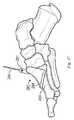
- FIG. 1is medial view of a foot illustrating anatomic reference planes and relative directions
- FIG. 2is a lateral view of a foot illustrating dorsiflexion and plantar flexion
- FIG. 3is a coronal view of a foot illustrating inversion and eversion
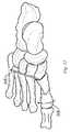
- FIG. 4is a dorsal view illustrating bones, tendons, and ligaments of the foot
- FIG. 5is a plantar view illustrating bones, tendons, and ligaments of the foot
- FIG. 6is a perspective view illustrating bones, tendons, and ligaments of the foot
- FIG. 7is a medial view of the MTP joint of the first ray of the foot
- FIG. 8is a sectional view taken along line 8 - 8 of FIG. 7 ;
- FIG. 9is a dorsal view of the MTC joint of the first ray of the foot.
- FIG. 10is a medial view of the MTC joint of the first ray of the foot
- FIG. 11is a dorsal view illustrating deformity of the foot
- FIG. 12is a plantar view illustrating deformity of the foot
- FIG. 13is a sectional view similar to that of FIG. 8 but illustrating deformity of the foot
- FIG. 14is dorsal view of bones of the first ray of a human foot illustrating coordinate axes according to the present invention
- FIG. 15is a medial view of the bones of FIG. 14 illustrating coordinate axes according to the present invention.
- FIG. 16is a dorsal view of a metatarsus illustrating coordinate axes according to the present invention.
- FIG. 17is a medial view of the metatarsus of FIG. 16 illustrating coordinate axes according to the present invention
- FIG. 18is an anterior view of the metatarsus of FIG. 16 illustrating coordinate axes according to the present invention
- FIGS. 19A-19Dare schematic views illustrating the orientation of a metatarsus before and after an osteotomy according to the present invention.
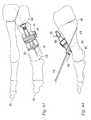
- FIGS. 20 and 21are isometric views of a saw blade according to the present invention.
- FIG. 22is a side view of the saw blade of FIGS. 20 and 21 ;
- FIG. 23is an isometric view of a cut block according to the present invention.
- FIGS. 24-28are orthographic views of the cut block of FIG. 23 ;
- FIGS. 29-34are orthographic views of a cut guide according to the present invention.
- FIG. 35is an isometric view of an axis guide according to the present invention.
- FIGS. 36-41are orthographic views of the axis guide of FIG. 35 ;
- FIGS. 42-54illustrate a method of performing an osteotomy on a bone according to the present invention
- FIG. 55is an isometric view of a cut guide according to the present invention.
- FIG. 56is another isometric view of the cut guide of FIG. 55 ;
- FIGS. 57-61are orthographic views of the cut guide of FIG. 55 ;
- FIG. 62is a top plan, or dorsal, view of a set of cut guides including the cut guide of FIG. 55 and additional similar guides having varying sizes and orientation;
- FIGS. 63-65illustrate a method of performing an osteotomy on a bone according to the present invention utilizing one of the cut guides of FIG. 62 .
- the following illustrative examplesdescribe implants, instruments and techniques for performing an osteotomy.
- the present inventionmay be used to perform osteotomies on any bone including but not limited to a tibia, fibula, femur, pelvis, humerus, ulna, radius, metacarpal, and metatarsal.
- While instruments and techniques according to the present inventionmay be used in conjunction with any bone or joint, the illustrative examples are shown in a size and form most suitable for the joints of the hand and foot.
- the hand and foothave a similar structure. Each has a volar aspect. In the hand the volar, or palmar, aspect includes the palm of the hand and is the gripping side of the hand. In the foot the volar, or plantar, aspect is the sole of the foot and is the ground contacting surface during normal walking. Both the hand and foot have a dorsal aspect opposite the volar aspect. Both the hand and foot include long bones generically described as metapodial bones. In the hand, the metapodial bones are referred to as metacarpal bones.
- the metapodial bonesare referred to as metatarsal bones.
- Both the hand and footinclude a plurality of phalanges that are the bones of the digits, i.e. the fingers and toes.
- each of the most proximal phalangesforms a joint with a corresponding metapodial bone.
- the inventionwill be illustrated with reference to a metatarsus of the first ray of a human foot.
- FIG. 1illustrates the orientation of anatomic planes and relative directional terms that are used for reference in this application.
- the coronal plane 10extends from medial 12 (toward the midline of the body) to lateral (away from the midline of the body) and from dorsal 14 (toward the top of the foot) to plantar 16 (toward the sole of the foot).
- the sagittal plane 18extends from anterior 20 (toward the front of the body) to posterior 22 (toward the back of the body) and from dorsal 14 to plantar 16 .
- the transverse plane 24extends anterior 20 to posterior 22 and medial to lateral parallel to the floor 26 .
- Relative positionsare also described as being proximal or distal where proximal is along the lower extremity toward the knee and distal is along the lower extremity toward the toes.
- the following examplesserve to demonstrate the relative directions.
- the great toeis medial of the lesser toes and the fifth toe is lateral of the great toe.
- the toesare distal to the heel and the ankle is proximal to the toes.
- the instepis dorsal and the arch is plantar.
- the toenailsare dorsal and distal on the toes.
- FIG. 2illustrates dorsiflexion 23 in which the toes are moved dorsally, or closer to the shin, by decreasing the angle between the dorsum of the foot and the leg and plantar flexion 25 in which the toes are moved plantar, or further away from the shin, by increasing the angle between the dorsum of the foot and the leg.
- the ankleis dorsiflexed and when one walks on their toes, the ankle is plantar flexed.
- FIG. 3illustrates inversion 27 in which the sole of the foot is tilted toward the sagittal plane or midline of the body and eversion 29 in which the sole of the foot is tilted away from the sagittal plane.
- FIGS. 4-10illustrate the arrangement of the bones within the foot 30 .
- a right footis illustrated. Beginning at the proximal aspect of the foot, the heel bone or calcaneus 32 projects plantar.
- the talus 34is dorsal to the calcaneus 32 and articulates with it at the talocalcaneal or subtalar joint. Dorsally, the talus articulates medially with the tibia 36 and laterally with the fibula 38 at the ankle joint.
- Distal to the ankleare the navicular bone 40 medially and the cuboid bone 42 laterally which articulate with the talus and calcaneus respectively.
- the navicular bone 40 and cuboid bone 42may also articulate with one another at the lateral side of the navicular bone and the medial side of the cuboid bone.
- Three cuneiform boneslie distal to the navicular bone and articulate with the navicular bone and one another.
- the first, or medial, cuneiform 44is located on the medial side of the foot 30 .
- the second, or intermediate, cuneiform 46is located lateral of the first cuneiform 44 .
- the third, or lateral, cuneiform 48is located lateral of the second cuneiform 46 .
- the third cuneiform 48also articulates with the cuboid bone 42 .
- the metatarsals 50 , 52 , 54 , 56 , 58extend distally from and articulate with the cuneiform and cuboid bones.
- the metatarsalsare numbered from 1 to 5 starting with the first metatarsal 50 on the medial side of the foot and ending with the fifth metatarsal 58 on the lateral side of the foot 30 .
- the first metatarsal 50articulates with the first cuneiform 44 at a metatarsocuneiform (MTC) joint 51 .
- the second metatarsal 52articulates with the first, second and third cuneiforms 44 , 46 , 48 and may articulate with the first metatarsal as well.
- proximal phalanges 60 , 62 , 64 , 66 , 68extend distally from and articulate with the five metatarsals respectively.
- the first proximal phalanx 60articulates with the first metatarsal 50 at a metatarsophalangeal (MTP) joint 61 .
- One or more distal phalanges 70 , 72 , 74 , 76 , 78extend distally from the proximal phalanges.
- the first metatarsal 50 , first proximal phalanx 60 , and, first distal phalanx 70together are referred to as the first ray of the foot.
- the metatarsal, proximal phalanx, and distal phalanges corresponding to the lesser digitsare referred to as the second through fifth rays respectively.
- FIG. 4is a dorsal view illustrating bones, tendons and ligaments of the foot. Plantar structures illustrated in FIG. 5 are omitted from FIG. 4 for clarity.
- the extensor hallucis longus muscleoriginates in the anterior portion of the leg, the extensor hallucis longus tendon 80 extends distally across the ankle and along the first ray to insert into the base of the distal phalanx 70 .
- the tibialis anterior muscleoriginates in the lateral portion of the leg and the tibialis anterior tendon 82 extends distally across the ankle and inserts into the first cuneiform 44 and first metatarsus 50 at the first MTC joint 51 where it contributes to the MTC capsular structure 84 ( FIGS.
- a transverse intermetatarsal ligament 83inserts into the capsule of the MTP joint such that it connects the heads of the first through fifth metatarsal bones.
- FIGS. 4 and 5only the connection between the first and second metatarsal bones 50 , 52 is shown.
- FIG. 5is a plantar view illustrating bones, tendons, and ligaments of the foot. Dorsal structures shown in FIG. 4 are omitted from FIG. 5 for clarity.
- the peroneus longus muscleoriginates at the head of the fibula and its tendon 86 passes posteriorly around the lateral malleolus 88 of the ankle, around the cuboid notch 90 on the lateral side of the cuboid bone 42 , along the peroneal sulcus 92 on the plantar surface of the cuboid bone 42 , and inserts into the first metatarsal 50 .
- the flexor hallucis brevis muscle 94originates from the cuboid 42 and third cuneiform 48 and divides distally where it inserts into the base of the proximal phalanx 60 .
- Medial and lateral sesamoid bones 96 , 98are present in each portion of the divided tendon at the MTP joint 61 .
- the sesamoids 96 , 98articulate with the plantar surface of the metatarsal head in two grooves 100 , 102 separated by a rounded ridge, or crista 104 ( FIG. 8 ).
- the flexor hallucis longus muscleoriginates from the posterior portion of the fibula 38 .
- the flexor hallucis longus tendon 106crosses the posterior surface of the lower end of the tibia, the posterior surface of the talus, runs forward between the two heads of the flexor hallucis brevis 94 , and is inserted into the base of the distal phalanx 70 of the great toe.
- FIG. 7is a medial view of tendons at the MTP joint 61 of the first ray.
- a medial collateral ligament 108originates from the head of the first metatarsus 50 and inserts into the proximal phalanx 60 .
- a medial metatarsosesamoid ligament 110originates from the head of the first metatarsus 50 and inserts into the medial sesamoid bone 96 .
- Similar collateral and metatarsosesamoid ligamentsare found on the lateral side of the first MTP joint.
- the flexor hallucis brevis 94is shown inserting into the sesamoids 96 , 98 .
- Ligamentous fibersextend further distally in the form of a phalangealsesamoid ligament 112 from the sesamoids to the proximal phalanx 60 .
- FIG. 8is a sectional view taken along line 8 - 8 of FIG. 7 showing the metatarsal head 50 , the tendon of the extensor hallucis longus 80 , the medial and lateral sesamoid bones 96 , 98 , the grooves 100 , 102 in which the sesamoids articulate, the crista 104 separating the grooves, the flexor hallucis longus 106 , the abductor hallucis 114 , and the adductor hallucis 116 .
- FIG. 9is a dorsal view showing the dorsal capsular structure 84 of the MTC joint 51 of the first ray including the insertion of the tibialis anterior tendon 82 .
- FIG. 10is a medial view of the MTC joint 51 of the first ray showing the medial capsular structure 118 including the insertion of the tibialis anterior tendon 82 .
- FIGS. 11-13illustrate deformities of the first ray.
- an intermetatarsal angle (IMA) 120may be measured between the longitudinal axes of the first and second metatarsal bones 50 , 52 .
- the angleis considered abnormal when it is 9 degrees or greater and the condition is known as metatarsus primus varus (MPV) deformity.
- MPVmetatarsus primus varus
- a hallux valgus angle (HVA) 122may be measured between the longitudinal axes of the first metatarsus 50 and the first proximal phalanx 60 at the MTP joint 61 .
- the angleis considered abnormal when it is 15 degrees or greater and the condition is known as a hallux valgus (HV) deformity.
- HVhallux valgus
- MPV and HVAoften occur together as shown in FIGS. 11-12 .
- the deformitiesprogress several changes may occur in and around the MTC and MTP joints.
- the extensors 80 , flexors 106 , abductors 114 , and adductors 116 of the first rayare shifted laterally relative to the MTP joint.
- the tendonsexert tension lateral to the MTP joint creating a bow string effect (as best seen in FIGS. 11 and 12 ) that tends to cause the deformities to increase.
- the relative shift of the sesamoids 96 , 98is often accompanied by erosion of the crista 104 .
- the abnormal muscle forcescause the metatarsus 50 to pronate, or in other words, rotate so that the dorsal aspect of the bone moves medially and the plantar aspect moves laterally. Rotation in the opposite direction is referred to as supination.
- Soft tissues on the medial side of the MTP joint and lateral side of the MTC jointattenuate, through lengthening and thinning, thus weakening the capsule and permitting the deformities to progress.
- Soft tissues on the opposite sides of the capsuletend to shorten, thicken and form contractures making it difficult to reduce the joints to their normal angular alignment.
- deformities of the first raymay include metatarsus primus varus, hallux valgus, abnormal pronation, abnormal supination, abnormal dorsiflexion, and/or abnormal plantar flexion. These deformities correspond to three different planar rotations. Metatarsus primus varus and hallux valgus result from rotations in the transverse plane 24 . Pronation and supination are rotation in the coronal plane 10 . Dorsiflexion and plantar flexion are rotation in the sagittal plane.
- suture and suture strandare used herein to mean any strand or flexible member, natural or synthetic, able to be passed through material and useful in a surgical procedure.
- transverseis used herein to mean crossing as in non-parallel.
- FIGS. 14 and 15illustrate the medial cuneiform 200 , first metatarsus 202 , and proximal phalanx 204 of the first ray of a human foot with overlying coordinate axes.
- FIG. 14is a dorsal view, looking down, on the first ray.
- FIG. 15is a medial view, looking from the medial side, of the first ray.
- the Z-axisis positive plantar, the X-axis is positive medial, and the Y-axis is positive distal.
- the Y-axisis parallel to the anatomic axis of the first metatarsus.
- the Y-Z planeis a local, first metatarsal sagittal plane and in a healthy foot is rotated slightly medial about the Z-axis relative to the sagittal plane of the body.
- the X-Y planeis a local, first metatarsal transverse plane and in a healthy foot is rotated slightly dorsal about the X-axis relative to the transverse plane of the body due to the natural angle of the foot.
- the X-Z planeis a local, first metatarsal coronal plane and in a healthy foot is rotated slightly anterior about the X-axis relative to the coronal plane of the body due to the natural angle of the foot.
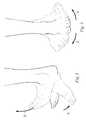
- FIGS. 16-18illustrate the metatarsus 202 alone with the coordinate axes of FIGS. 14 and 15 . Rotation about each of the axes is shown. Referring to FIG. 16 , rotation in the X-Y plane about the Z-axis results in a change in the IMA. Referring to FIG. 17 , rotation in the Y-Z plane about the X-axis results in a change in dorsiflexion/plantarflexion. Referring to FIG. 18 , rotation in the X-Z plane about the Y-axis results in a change in pronation/supination. In the case of an osteotomy, a cut is made in a bone to change the position of one portion of the bone relative to another portion.
- a cylindrical cut 208also referred to as a crescentic cut, concentric with the Z-axis allows a change in IMA by rotating the cut surfaces relative to one another about the Z-axis.
- a cylindrical cut 210concentric with the X-axis allows a change in flexion angle by rotating the cut surfaces relative to one another about the X-axis.
- a planar cut 212 parallel to the X-Z planeallows a change in pronation/supination by rotating the cut surfaces about the Y-axis ( FIG. 18 ).
- an oblique cuti.e. a cut angled relative to two or three axes, that results in simultaneous angular changes in 2 or 3 anatomic planes.
- an initial position 214 of a bone portion axiscan be changed by rotating the bone portion about two axes to a new position 216 .
- thiswould correspond to plantar flexing the metatarsus by an angular amount 218 corresponding to a plantar displacement 220 of the distal head 206 and decreasing the IMA an angular amount 222 corresponding to a lateral displacement 224 of the distal head 206 .
- the bone cutmay be a crescentic cut coaxial with the bi-planar rotation axis 228 or a planar cut normal to the bi-planar rotation axis 228 .
- the angle of the bi-planar rotation axis 228may make either a crescentic cut or a planar cut more practical.
- an additional rotation about the bone axis from the initial position 214 to the new position 216may be included and when combined with the other two motions results in a tri-planar rotation axis 230 about which a rotation will result in a tri-planar correction.
- this additional rotationcorresponds to a change in pronation/supination of the metatarsus about its anatomic axis.
- a first planemay be constructed containing the bi-planar rotation axis 228 and the initial position 214 of the bone portion axis.
- a second planemay be constructed containing the bi-planar rotation axis 228 and the new position 216 of the bone portion axis.
- a bisector plane 215contains the bi-planar rotation axis 228 , the tri-planar rotation axis 230 and is angularly spaced half-way between the initial and new positions 214 , 216 .
- FIG. 19Cillustrates the motion of the end of the metatarsus 202 in a motion plane 217 ( FIG. 19B ) perpendicular to the bisector plane 215 for the case of rotation about the bi-planar rotation axis 228 .
- a reference mark 219is included to illustrate the pronation/supination of the bone.
- FIG. 19Dillustrates the motion of the end of the metatarsus 202 in the motion plane 217 for the case of rotation about the tri-planar rotation axis 230 .
- the end of the metatarsusWith rotation about the tri-planar rotation axis 230 , the end of the metatarsus translates medial/lateral 221 , translates dorsal/plantar 223 and rotates 225 in pronation/supination from the initial position 214 to the new position 216 .
- the bi-planar rotation axis 228lies in the X-Z plane at an angle ⁇ 227 relative to the Z-axis.
- the tri-planar rotation axis 230lies in the bisector plane 215 at an angle ⁇ 229 from the bi-planar rotation axis 228 .
- ⁇the change in IMA 222
- ⁇the change in pronation/supination 225
- Lthe metatarsal axis length from the rotation axis to the joint line of the MTP joint
- Cthe dorsal/plantar displacement 220 of the metatarsal head
- Rthe ratio C/L
- a desired positional change in each planemay be determined.
- the current and desired positionsmay be determined by medical imaging, computer modeling, manual measurement, or other techniques as is known in the art.
- the desired positional changemay be expressed as an angular change or, for a given position relative to the osteotomy location, it may be expressed as a displacement.
- the positional changemay be expressed as either an angle or a displacement.
- plantar flexionis expressed as an amount of plantar displacement of the distal head of the metatarsus, based either a gauged metatarsal axis length L or an estimated metatarsal axis length L determined as the difference between an average metatarsus overall length and a gauged distance from the proximal end of the metatarsus to the osteotomy.
- An illustrative method according to the present inventionproduces an osteotomy between a first bone portion and a second bone portion.
- the bone portionsdefine a first relative position between them.
- the methodincludes defining a rotation axis or a corresponding rotation plane in fixed relationship to the bone, referencing a cutter to the rotational axis or plane, cutting the bone to mobilize the first and second bone portions relative to one another, and rotating the first bone portion relative to the second bone portion within the rotation plane and/or about the rotational axis.
- the rotational axis and planeincorporate a desired positional change in one or more planes, preferably in two or three anatomic planes.
- an axis guidemay be provided that defines one or more rotational axes.
- Each rotational axismay incorporate an angular change in one or more anatomic reference planes.
- Each rotational axismay be incorporated into the axis guide by, e.g., calculating angles ⁇ 227 and ⁇ 229 as described above for a particular combination of corrections.
- the axis guidemay then be modeled along with features operable to orient the guide relative to anatomic reference planes.
- Each rotational axismay then be superimposed on the model relative to the same anatomic reference planes and be used to define a feature such as a hole, pin, slot, groove, intersecting surfaces, or other suitable features corresponding to the rotational axis or corresponding rotational plane.
- a cuttermay be referenced to one of the rotation axes or rotational planes and guided to mobilize the first and second bone portions relative to one another. The bone portions may then be relatively rotated within the rotational plane and/or about the rotation axis, to realize the angular change in the one or more reference planes.
- the cuttermay be linked directly to the axis guide.
- the axis guidemay be used to provide a feature such as a hole or pin in the bone defining the rotation axis which is referenced by the cutter.
- the axis guidemay be removed prior to referencing the cutter to the rotation axis.
- the axis guidemay include a guide hole corresponding to each rotation axis and the guide hole may be used to place a pin in the bone aligned with a desired rotation axis and the axis guide may then be removed.
- a cuttermay then engage the pin for rotation about the pin to create a cylindrical cut in the bone about which the bone portions may be relatively rotated.
- a cut guide defining a cut planemay be referenced to the pin.
- a cuttermay then be guided in the cut plane to create a planar cut between the bone portions.
- the bone portionsmay then be rotated about the rotation axis.
- a cut guidedefining one or more rotation planes corresponding to one or more predetermined multi-planar corrections may be provided.
- the cut guidemay be referenced to the bone and used to guide a cutter to create a planar cut between the bone portions without first creating a rotation axis in or on the bone.
- the rotation plane or planes corresponding to the rotation axesare defined by the guide and the guide is positioned on the bone by aligning reference features of the guide with the bone to orient the guide to correctly position the one or more rotation planes.
- the guidemay then be used to guide a cutter directly to create a planar cut in the bone corresponding the to the desired rotation plane.
- the freed bone portionsmay then be rotated in the rotation plane to achieve the multi-planar correction.
- FIGS. 20-22depict an illustrative crescentic blade 250 .
- the blade 250has a thin wall 252 forming a portion of a cylinder curved about a blade axis 254 and extending from a proximal end 256 to a distal end 258 . Teeth 260 are formed on the distal end 258 .
- the proximal end 256is attached to a shaft 262 coaxial with the blade axis 254 .
- the shaft 262may be attached to a powered handpiece to rotate the blade about the blade axis and form a cylindrical cut in a bone. By using an oscillating motion, a cut transcribing an arc of a cylinder can be made.
- the shaft 262may include an axial bore 264 coaxial with the blade axis 254 able to receive a pin in rotational engagement for guiding the blade in rotation about the pin.
- FIGS. 23-28depict an illustrative cut block 270 .
- the cut block 270has a bore 272 defining a rotation axis 274 .
- the bore 272is able to receive a pin in axial sliding and rotational relationship.
- the cut blockincludes a curved surface 276 defining at least a portion of a cylinder parallel to the rotation axis 274 .
- the cut block 270may be pinned to a bone by placing a pin through the bore 272 and into the bone.
- a second pinmay be placed through a second bore 278 and into the bone to prevent the cut block from rotating about the first pin.
- a cuttersuch as the crescentic blade 250 of FIGS. 20-22 , may be guided to form a cut about the rotation axis 274 of the cut block by pressing the curved blade against the curved surface 276 .
- FIGS. 29-34depict an illustrative blade guide 280 .
- the blade guide 280includes a shaft 282 having a bore 284 defining an axis 286 extending between a proximal end 288 and a distal end 290 .
- a set screw 291is contained in a hole transverse to the bore 284 .
- the set screw 291may be tightened to lock the blade guide 280 to a pin received in the bore 284 .
- the blade guide 280defines a plane 281 , normal to the bore axis 286 , for guiding a cutter, e.g. a saw blade, to make a planar cut in a bone.
- a cuttere.g. a saw blade
- a surface 292 formed near the distal end 290defines the plane. More particularly in the illustrative example of FIGS. 29-34 , a pair of opposing surfaces defines a slot 294 between them able to receive a saw blade and constrain it to motion in a plane.
- the blade guide 280is narrow proximally and wide distally to provide clearance for soft tissues while providing a wide slot 294 allowing the blade to be swept from side to side within the slot 294 .
- the distal end 290is offset 296 from the axis 286 so that the bore 284 can be placed on a pin in a bone and the distal end 290 be placed beside the bone.
- the distal end 290is curved as seen in FIGS. 29 and 34 to accommodate the particular anatomy of the illustrative example for use on a metatarsus of a human foot.
- FIGS. 35-41depict an illustrative axis guide 310 .
- the axis guide 310is used to establish a rotation axis on a bone for guiding an osteotomy cut.
- the axis guide 310includes at least one guide hole able to define a rotation axis on a bone.
- the guide holemay be referenced directly.
- itmay be used to guide a drill to form a hole in a bone such that the hole may be referenced to guide a cutter.
- the guide holemay guide the placement of a pin that may be referenced to guide a cutter.
- the guide holeWhen the guide is aligned with a bone, the guide hole defines a rotation axis corresponding to a positional change that may be produced by an osteotomy in which a cutter is referenced to the rotation axis.
- the position changemay include changes in one or more anatomic planes.
- the axis guide 310includes multiple guide holes, each guide hole defining a rotational axis corresponding to a different positional change between first and second bone portions in at least two anatomic reference planes.
- 35-41is configured for establishing rotational axes for a metatarsal osteotomy to produce a positional change in IMA, pronation, and plantar flexion.
- the plantar flexionis expressed on the guide as a change in plantar displacement of the distal head of the metatarsus.
- the axis guide 310includes rows 312 and columns 314 of guide holes in which each guide hole corresponds to a unique combination of change in IMA, pronation, and plantarflexion. Indicia may be provided on the axis guide 310 to indicate the amount of change produced in one or more of IMA, pronation, and plantarflexion, using each guide hole.
- the guide holesdefine axes that are angled relative to one another in at least two rotational degrees of freedom.
- the axis guide 310may be one of a set of axis guides in which each axis guide has a fixed plantarflexion positional change applied to each guide hole.
- the particular axis guide 310 showncorresponds to a fixed plantarflexion positional change corresponding to 2.5 mm of plantar displacement of the distal head of the metatarsus for a rotational axis a predetermined distance from the distal head of the metatarsus. The setting of that predetermined distance is shown later in this disclosure.
- the positional changeis expressed in terms of plantar displacement for convenience.
- a surgeontypically is interested in preserving the plantar position of the distal head of the metatarsus or offsetting it a fixed amount. Therefore, it is convenient to have guides with a fixed plantar change and variable IMA and pronation changes.
- the guide hole 316 in the row labeled 0 degrees of pronation and the column labeled 15 degrees of IMAwill establish a rotational axis to guide an osteotomy that when rotated to decrease the IMA by 15 degrees will also result in 0 degrees of pronation correction and a 2.5 mm plantar shift of the distal head of the metatarsus.
- Axis guidesmay be provided that incorporate IMA changes corresponding to any clinically expedient amount, e.g., with the goal of reducing the IMA to fall within a normal anatomic range.
- Preferably axis guidesare provided that incorporate an IMA reduction ranging from 0 to 25 degrees; more preferably from 5 to 15 degrees.
- the guidesmay incorporate pronation correction corresponding to any clinically expedient amount, e.g., with the goal of correcting pronation to fall within a normal anatomic range.
- axis guidesare provided that incorporate a pronation correction ranging from 0 to 15 degrees; more preferably from 0 to 10 degrees.
- the guidesmay incorporate plantarflexion changes corresponding to any clinically expedient amount.
- axis guidesare provided that incorporate a plantar shift ranging from 0 to 5 mm; more preferably 0 to 2.5 mm.
- An alignment referenceis provided to align the axis guide 310 to anatomic features of the bone so that the positional changes are referenced to the anatomic planes.
- An alignment referencemay include a mark, line, plane, projection, or other suitable reference.
- a dorsal-plantar through hole 330 and a distal hole 332are provided to receive dorsal and distal alignment rods 334 , 336 that are used to align the axis guide 310 .
- the dorsal-plantar hole 330may extend through the axis guide 310 , as shown, to permit the dorsal alignment rod 334 to be driven through the axis guide 310 and into underlying bone to fix the axis guide 310 to the bone. It is advantageous to offset the holes 330 , 332 medial-laterally as shown in FIGS. 37 and 40 so that the alignment rods 334 , 336 do not collide.
- the distal alignment rod 336may include an optional plantar directed pointer 338 at its distal end as an alignment aid. For example, the distal end of the distal alignment rod 336 may be bent to create the pointer 338 .
- the plantar surface 340 of the axis guide 310is concave medial-laterally to help stabilize it as it sits on the dorsal surface of a bone.
- An additional fixation hole 342 through the axis guide 310may be used to provide additional fixation of the axis guide 310 to an underlying bone.
- FIGS. 42-54depict an illustrative method according to the invention.
- the illustrative instruments of FIGS. 20-41are shown in use to perform an osteotomy on a metatarsus of the first ray of a human foot for changing the alignment of the first ray.
- the illustrative axis guide 310 of FIGS. 35-41has been placed on the metatarsus 202 .
- the dorsal alignment rod 334is aligned with the local sagittal plane of the metatarsus 202 .
- the distal alignment rod 336is aligned parallel to the metatarsal anatomic axis 402 .
- the optional pointer 338may be aligned with e.g. the joint line of the MTP joint to position the axis guide 310 at a predetermined distance from the distal head 206 .
- angular changes in the position of the distal head 206may optionally be expressed as displacements.
- the change in dorsiflexionis indicated on the axis guide 310 as a plantar displacement of the metatarsal head.
- the dorsal alignment rod 334may be driven into the metatarsus to temporarily fix the axis guide 310 in the aligned position.
- an additional pin 344has been placed through the additional fixation hole 342 to further stabilize the axis guide 310 .
- an axis pin 346has been placed through the axis hole corresponding to a 15 degree change in IMA and a 5 degree change in pronation.
- the particular axis guide 310also incorporates a 2.5 mm distal plantar displacement into each of the axis holes.
- FIG. 46alignment rods 334 and 336 , the fixation pin 344 , and the axis guide 310 have been removed leaving just the axis pin 346 establishing the rotation axis for a 15 degree IMA, 5 degree pronation, and 2.5 mm distal plantar displacement corrective osteotomy.
- the cannulated crescentic saw blade 250has been placed over the axis pin 346 and rotated about the rotational axis pin 346 to produce a cylindrical cut 347 through the metatarsus 202 .
- the cut block 270may be placed over the rotational axis pin 346 .
- the crescentic blade 250may be guided on the cut block 270 alone, without engaging the pin 346 , or the blade 250 may engage both the cut block 270 and the rotational axis pin 346 .
- the distal portionis reduced to the desired IMA which will simultaneously change the pronation angle and plantar position of the distal bone portion.
- the bone portionsmay then be fixed with pins, screws, plates or other suitable fixation elements.
- the blade guide 280has been placed over the rotational axis pin 346 and adjusted to align with a desired cut plane on the metatarsus 202 .
- the set screw 291is tightened to lock the blade guide 280 in place on the axis pin 346 .
- a saw blade(not shown) is guided in the slot 294 to form a planar cut surface through the bone.
- the distal portionis reduced to the desired IMA which will simultaneously change the pronation angle and plantar position of the distal bone portion.
- the bone portionsmay then be fixed with pins, screws, plates or other suitable fixation elements.
- the rotational axis pin 346may preferably be advanced partway into the bone as shown in FIG. 48 prior to cutting the bone so that the tip of the pin is dorsal to the slot 294 .
- the bonemay then be cut partially through, including under the rotational axis pin 346 .
- the set screw 291may be loosened and the rotational axis pin 346 driven plantar past the planar cut as shown in FIG. 49 .
- the set screw 291may be retightened and the remainder of the bone cut through.
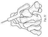
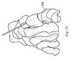
- the bone cut 350is shown in FIGS. 50 and 51 . In this way, the rotational axis pin 346 captures the cut bone portions.
- FIGS. 52-54shows the bone with the blade guide 280 removed and the rotational axis pin 346 capturing the cut bone portions.
- the bone portionshave been rotated as indicated by arrow 348 about the rotational axis pin to the desired IMA ( FIG. 52 ) simultaneously changing the pronation angle ( FIG. 53 ) and plantar position ( FIG. 54 ) of the distal bone portion.
- FIGS. 55-61illustrate an alternative cut guide 400 .
- the cut guidemay be used to directly guide a cutter, such as a planar saw blade, to create a rotation plane between bone portions corresponding to a multi-planar correction as described relative to the examples above.
- the cut guide 400includes a cutter guiding feature defining a rotation plane and includes reference features that are alignable with a bone to place the guide in a predetermined orientation relative to the bone.
- the cutter guiding surfaceis normal to a rotation axis determined as described above.
- the rotation axisis not discretely defined with a hole or pin but rather the corresponding plane is defined and referenced to the bony anatomy with the reference features.
- the guide 400includes a guide body 402 having a proximal end 404 , a distal end 406 opposite the proximal end, a medial side 408 , a lateral side 410 opposite the medial side, a top surface 412 , and a bottom surface 414 opposite the top.
- the guide body 402includes a fixation feature to temporarily secure the guide body 402 to a bone.
- the fixation featuresmay include one or more roughened surface, spike, hole for receiving a pin or screw, strap, or other fixation feature known in the art.
- the fixation featureinclude holes 416 , 418 extending through the guide body 402 from the top surface 412 to the bottom surface 414 and configured to receive a fixation member such as a pin or screw that extends though the guide body 402 and into the bone.
- a fixation membersuch as a pin or screw that extends though the guide body 402 and into the bone.
- the holes 416 and 418are coplanar but not parallel.
- the hole axesdefine a reference plane that can be used to align the guide.
- smooth pins inserted through the holes and into an underlying bonewill secure the guide body 402 to the bone and prevent it from lifting off of the bone.
- the holes 416 , 418define a plane including a guide body longitudinal axis 420 intersecting the hole axes 422 , 424 .
- the guide bodyincludes reference features for aligning the guide body with a metatarsus.
- the reference featuresinclude the bottom surface 414 , the proximal end 404 , and the longitudinal axis 420 defined by the holes 416 , 418 .
- the guide body 402includes a plurality of cutter guiding features, each corresponding to a different multi-planar correction.
- the cutter guiding featuresmay be, for example, planar surfaces, slots, or other features known in the art for guiding a cutter to form a planar surface on a bone.
- the cutter guiding featuresare in the form of saw blade slots 430 , 432 , 434 .
- Each slot 430 , 432 , 434is aligned relative to the reference features so that when bottom surface 414 is resting on the bone, the longitudinal axis 420 is aligned parallel with the metatarsal axis, the hole axes 424 , 426 are aligned within the sagittal plane, and the proximal end 404 is aligned with the MTC joint line, the slot will guide a saw blade to produce a rotation plane corresponding to a particular multi-planar correction.
- each slotis configured to produce 3 degrees of IMA correction and 10, 20, or 30 degrees of pronation correction.
- a slight amount of plantar displacement of the distal metatarsal headis included in each correction to compensate for shortening of the metatarsus due to the bone removed by the saw blade, i.e. the saw blade kerf.
- the amount of plantar displacementis an estimate based on an osteotomy-to-distal metatarsal head distance determined as the difference between the overall length of an average human first metatarsus and the distance from the MTC joint line to the osteotomy plane.
- the plantar displacementis designed to maintain the metatarsal head in the same plane it was in prior to the osteotomy to avoid changing the load balance between the five rays of the foot.
- Typical values of plantar displacementare in the range of 0.1 mm to 3 mm.
- the slots 430 , 432 , 434define planes that are angled relative to one another in at least two rotational degrees of freedom.
- Indicia 436 , 438 printed on the guide body 402indicate the IMA correction associated with all of the saw slots on the guide 400 and the different pronation correction associated with each of the saw slots. Additional indicia 440 printed on the guide body 402 indicates that the guide 400 is configured for a right foot.
- a handlemay be provided to aid in manipulating the guide 400 .
- a handle interface 442is formed on the medial side to engage a modular, removable handle (not shown).
- the handle interfacemay include a slot, tab, dovetail, or other feature as is known in the art for coupling to a modular handle.
- FIG. 62depicts an exemplary kit 450 having a tray 452 for housing the guide 400 of FIG. 55 along with additional guides offering a variety of configurations.
- a plurality of guides 400 , 454 , 456 configured for a right footis provided on one side of the tray 452 and a plurality of guides 458 , 460 , 462 configured for a left foot is provided on another side of the tray.
- each guideprovides for either 3, 6, or 9 degrees of IMA correction and the choice of 10, 20, or 30 degrees of pronation correction. All of the guides provide a fixed additional plantar displacement.
- the kitallows a surgeon to select a guide corresponding to a left or right foot and having a desired amount of IMA correction. After selecting the appropriate guide, the surgeon may then select the amount of pronation correction by choosing the corresponding saw slot.
- the traymay include other items useful in the osteotomy procedure such as fixation pins 464 .
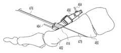
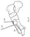
- FIGS. 63-65illustrate an osteotomy procedure using the kit 450 .
- FIG. 63is a dorsal view of the first and second rays 470 , 472 of a right foot having an IMA of approximately 19 degrees.
- a guide 456is selected from the kit 450 corresponding to a 9 degree IMA correction.
- the guide 456is mounted on the metatarsus 474 with the bottom of the guide 456 resting on the longitudinal axis 420 of the guide, the longitudinal axis 420 parallel to the metatarsal longitudinal axis, the plane containing the fixation hole axes 426 , 424 aligned parallel to the sagittal plane, and the proximal end aligned with the MTC joint.
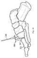
- the surgeonselects the saw slot corresponding to a 10 degree pronation correction and uses it to guide a saw blade 476 to form a cut 478 defining a rotation plane 479 between proximal and distal portions 480 , 482 of the metatarsus.
- the distal portion of the metatarsus along with the phalanges 484 , 486have been rotated within the plane 479 defined by the cut 478 to reduce the IMA by 9 degrees as well as correct the pronation by 10 degrees and produce a compensating plantar displacement of the metatarsal head.
- the surgeonmay fine tune the position of the distal portion of the first ray by sliding the cut surfaces in addition to rotating them.
- the osteotomymay be fixed using pins, screws, plates, or other devices and methods as is known in the art.
- Various illustrative examples of devices and methods of producing a multi-planar osteotomy on a bonehave been provided.
- Examples of guideshave been provided that can be used to define a rotation axis and/or corresponding rotation plane in three rotational degrees of freedom relative to a bone to perform a tri-planar rotational osteotomy. While such a guide may be used to perform a tri-planar rotational osteotomy on any bone, it has been illustrated for example to produce a tri-planar rotational osteotomy on a first metatarsus of a human foot to correct angular alignment of the first ray of the foot.
- an exemplary guidehas been disclosed that allows the surgeon to vary the value of one of the three angular degrees of freedom simply by choosing one of a plurality of guiding features such as a hole defining a rotation axis or a surface or slot defining a rotation plane.
- An exemplary guidehas been disclosed that allows the surgeon to vary the value of two of the three angular degrees of freedom by selecting one of a plurality of guiding features arranged in a matrix.
- Sets of guideshave been disclosed that allow the surgeon to intraoperatively vary a third angular degree of freedom.
- the angular degrees of freedommay be stated in terms of rotational degrees or as displacements if additional information is provided regarding the size and shape of the bone and the location of the osteotomy.
- Exampleshave been disclosed in which the angular degrees of freedom may be related to a metatarsus of a foot so that they correspond to, for example, IMA, pronation, and plantar flexion.
- Guideshave been disclosed that may be configured to allow user selectability of any one of IMA, pronation, and plantar flexion.
- Guideshave been disclosed that may be configured to allow user selectability of any two of IMA, pronation, and plantar flexion.
- Guideshave been disclosed as sets of guides that may be configured to allow user selectability of IMA, pronation, and plantar flexion.
- Guideshave been disclosed having a plurality of cutter guiding features differing in the amount of angular correction. It is within the scope of the invention to provide a single cutter guiding feature with an adjustable position to permit varying the value of one or more angular corrections. It will be understood that substitutions among the various examples and variations are within the scope of the invention. For example, more or fewer options with regard to correction angles may be provided, alternative fixation of the guide to the bone may be incorporated, and different corrections may be coupled on a particular guide. For example, a particular guide may have a fixed pronation correction and variable IMA correction or a particular guide or set of guides may have variable plantar displacement. Many combinations are possible and the present inventors have demonstrated multiple, but not a comprehensive listing of, examples illustrating some of the possible combinations of features within the scope of the invention.
Landscapes
- Health & Medical Sciences (AREA)
- Surgery (AREA)
- Life Sciences & Earth Sciences (AREA)
- Biomedical Technology (AREA)
- Medical Informatics (AREA)
- Oral & Maxillofacial Surgery (AREA)
- Dentistry (AREA)
- Engineering & Computer Science (AREA)
- Orthopedic Medicine & Surgery (AREA)
- Heart & Thoracic Surgery (AREA)
- Nuclear Medicine, Radiotherapy & Molecular Imaging (AREA)
- Molecular Biology (AREA)
- Animal Behavior & Ethology (AREA)
- General Health & Medical Sciences (AREA)
- Public Health (AREA)
- Veterinary Medicine (AREA)
- Surgical Instruments (AREA)
Abstract
Description
Claims (14)
Priority Applications (3)
| Application Number | Priority Date | Filing Date | Title |
|---|---|---|---|
| US15/047,666US10376268B2 (en) | 2015-02-19 | 2016-02-19 | Indexed tri-planar osteotomy guide and method |
| US16/534,857US11304705B2 (en) | 2015-02-19 | 2019-08-07 | Indexed tri-planar osteotomy guide and method |
| US17/655,349US20220202427A1 (en) | 2015-02-19 | 2022-03-17 | Indexed tri-planar osteotomy guide and method |
Applications Claiming Priority (2)
| Application Number | Priority Date | Filing Date | Title |
|---|---|---|---|
| US201562118378P | 2015-02-19 | 2015-02-19 | |
| US15/047,666US10376268B2 (en) | 2015-02-19 | 2016-02-19 | Indexed tri-planar osteotomy guide and method |
Related Child Applications (1)
| Application Number | Title | Priority Date | Filing Date |
|---|---|---|---|
| US16/534,857ContinuationUS11304705B2 (en) | 2015-02-19 | 2019-08-07 | Indexed tri-planar osteotomy guide and method |
Publications (2)
| Publication Number | Publication Date |
|---|---|
| US20160242791A1 US20160242791A1 (en) | 2016-08-25 |
| US10376268B2true US10376268B2 (en) | 2019-08-13 |
Family
ID=56690042
Family Applications (3)
| Application Number | Title | Priority Date | Filing Date |
|---|---|---|---|
| US15/047,666Active2038-02-24US10376268B2 (en) | 2015-02-19 | 2016-02-19 | Indexed tri-planar osteotomy guide and method |
| US16/534,857Active2036-07-10US11304705B2 (en) | 2015-02-19 | 2019-08-07 | Indexed tri-planar osteotomy guide and method |
| US17/655,349AbandonedUS20220202427A1 (en) | 2015-02-19 | 2022-03-17 | Indexed tri-planar osteotomy guide and method |
Family Applications After (2)
| Application Number | Title | Priority Date | Filing Date |
|---|---|---|---|
| US16/534,857Active2036-07-10US11304705B2 (en) | 2015-02-19 | 2019-08-07 | Indexed tri-planar osteotomy guide and method |
| US17/655,349AbandonedUS20220202427A1 (en) | 2015-02-19 | 2022-03-17 | Indexed tri-planar osteotomy guide and method |
Country Status (1)
| Country | Link |
|---|---|
| US (3) | US10376268B2 (en) |
Cited By (40)
| Publication number | Priority date | Publication date | Assignee | Title |
|---|---|---|---|---|
| US20200015865A1 (en)* | 2018-07-11 | 2020-01-16 | Crossroads Extremity Systems, Llc | Bunion correction system and method |
| US11304735B2 (en) | 2020-02-19 | 2022-04-19 | Crossroads Extremity Systems, Llc | Systems and methods for Lapidus repair of bunions |
| US11304705B2 (en) | 2015-02-19 | 2022-04-19 | Crossroads Extremity Systems, Llc | Indexed tri-planar osteotomy guide and method |
| US11497528B2 (en) | 2014-07-15 | 2022-11-15 | Treace Medical Concepts, Inc. | Bone positioning and cutting system and method |
| US20230027816A1 (en)* | 2021-07-22 | 2023-01-26 | Inverted Ortho, LLC | Oblique diaphyseal osteotomy system for metatarsal shortening |
| US11583323B2 (en) | 2018-07-12 | 2023-02-21 | Treace Medical Concepts, Inc. | Multi-diameter bone pin for installing and aligning bone fixation plate while minimizing bone damage |
| US11596443B2 (en) | 2018-07-11 | 2023-03-07 | Treace Medical Concepts, Inc. | Compressor-distractor for angularly realigning bone portions |
| US11602386B2 (en) | 2015-07-14 | 2023-03-14 | Treace Medical Concepts, Inc. | Bone positioning guide |
| US11602387B2 (en) | 2015-08-14 | 2023-03-14 | Treace Medical Concepts, Inc. | Bone positioning and preparing guide systems and methods |
| US11607250B2 (en) | 2019-02-13 | 2023-03-21 | Treace Medical Concepts, Inc. | Tarsal-metatarsal joint procedure utilizing compressor-distractor and instrument providing sliding surface |
| US11622797B2 (en) | 2020-01-31 | 2023-04-11 | Treace Medical Concepts, Inc. | Metatarsophalangeal joint preparation and metatarsal realignment for fusion |
| US11627954B2 (en) | 2019-08-07 | 2023-04-18 | Treace Medical Concepts, Inc. | Bi-planar instrument for bone cutting and joint realignment procedure |
| US11648019B2 (en) | 2015-09-18 | 2023-05-16 | Treace Medical Concepts, Inc. | Joint spacer systems and methods |
| US11690659B2 (en) | 2015-08-14 | 2023-07-04 | Treace Medical Concepts, Inc. | Tarsal-metatarsal joint procedure utilizing fulcrum |
| US11786257B2 (en) | 2015-01-07 | 2023-10-17 | Treace Medical Concepts, Inc. | Bone cutting guide systems and methods |
| US11844533B2 (en) | 2015-02-18 | 2023-12-19 | Treace Medical Concepts, Inc. | Pivotable bone cutting guide useful for bone realignment and compression techniques |
| USD1011524S1 (en) | 2022-02-23 | 2024-01-16 | Treace Medical Concepts, Inc. | Compressor-distractor for the foot |
| US11889998B1 (en) | 2019-09-12 | 2024-02-06 | Treace Medical Concepts, Inc. | Surgical pin positioning lock |
| US11890039B1 (en) | 2019-09-13 | 2024-02-06 | Treace Medical Concepts, Inc. | Multi-diameter K-wire for orthopedic applications |
| US11931106B2 (en) | 2019-09-13 | 2024-03-19 | Treace Medical Concepts, Inc. | Patient-specific surgical methods and instrumentation |
| US11931047B2 (en) | 2016-08-26 | 2024-03-19 | Treace Medical Concepts, Inc. | Osteotomy procedure for correcting bone misalignment |
| US11963703B2 (en) | 2015-07-14 | 2024-04-23 | Treace Medical Concepts, Inc. | Bone cutting guide systems and methods |
| US11963686B1 (en) | 2023-04-20 | 2024-04-23 | Fusion Orthopedics USA, LLC | Surgical systems and methods including cutting and aligning guides for performing an osteotomy |
| US11969193B2 (en) | 2015-05-06 | 2024-04-30 | Treace Medical Concepts, Inc. | Intra-osseous plate system and method |
| US11986251B2 (en) | 2019-09-13 | 2024-05-21 | Treace Medical Concepts, Inc. | Patient-specific osteotomy instrumentation |
| US12004789B2 (en) | 2020-05-19 | 2024-06-11 | Treace Medical Concepts, Inc. | Devices and techniques for treating metatarsus adductus |
| USD1051382S1 (en) | 2022-02-23 | 2024-11-12 | Treace Medical Concepts, Inc. | Lesser metatarsal cut guide |
| US12161371B2 (en) | 2021-01-18 | 2024-12-10 | Treace Medical Concepts, Inc. | Contoured bone plate with locking screw for bone compression, particularly across a tarsometatarsal joint |
| USD1057155S1 (en) | 2022-02-23 | 2025-01-07 | Treace Medical Concepts, Inc. | Lesser metatarsal cut guide with parallel cut faces |
| US12193683B2 (en) | 2021-05-20 | 2025-01-14 | Treace Medical Concepts, Inc. | Cut guide with integrated joint realignment features |
| USD1068078S1 (en) | 2023-02-08 | 2025-03-25 | Treace Medical Concepts, Inc. | Handle for an orthopedic instrument |
| USD1068077S1 (en) | 2023-02-08 | 2025-03-25 | Treace Medical Concepts, Inc. | Orthopedic rasp for preparing an intercuneiform joint |
| USD1075012S1 (en) | 2022-02-23 | 2025-05-13 | Treace Medical Concepts, Inc. | Metatarsal lateral release instrument |
| US12303140B2 (en) | 2023-04-20 | 2025-05-20 | Fusion Orthopedics USA, LLC | Surgical systems and methods including cutting and aligning guides for performing an osteotomy |
| US12310603B2 (en) | 2021-02-18 | 2025-05-27 | Treace Medical Concepts, Inc. | System and technique for metatarsal realignment with reduced incision length |
| USD1079011S1 (en) | 2022-02-23 | 2025-06-10 | Treace Medical Concepts, Inc. | Metatarsal cut guide with parallel cut faces |
| US12357347B2 (en) | 2017-02-26 | 2025-07-15 | Treace Medical Concepts, Inc. | Fulcrum for tarsal-metatarsal joint procedure |
| US12403012B2 (en) | 2019-07-26 | 2025-09-02 | Crossroads Extremity Systems, Llc | Bone repositioning guide system and procedure |
| US12414779B2 (en) | 2016-11-11 | 2025-09-16 | Treace Medical Concepts, Inc. | Devices and techniques for performing an osteotomy procedure on a first metatarsal to correct a bone misalignment |
| US12440250B2 (en) | 2024-02-05 | 2025-10-14 | Treace Medical Concepts, Inc. | Multi-diameter K-wire for orthopedic applications |
Families Citing this family (18)
| Publication number | Priority date | Publication date | Assignee | Title |
|---|---|---|---|---|
| EP4252686A3 (en) | 2012-12-28 | 2023-12-27 | Paragon 28, Inc. | Alignment guide apparatus |
| WO2017031020A1 (en) | 2015-08-14 | 2017-02-23 | Treace Medical Concepts, Inc. | Tarsal-metatarsal joint procedure utilizing fulcrum |
| EP3528716B1 (en)* | 2016-10-24 | 2024-02-14 | Paragon 28, Inc. | Osteotomy systems |
| ES2993743T3 (en) | 2017-02-27 | 2025-01-08 | Paragon 28 Inc | Targeting instruments and systems |
| EP3651699B1 (en) | 2017-07-11 | 2025-09-17 | Paragon 28, Inc. | Bone fixation system, assembly, implants, devices and insertion guides |
| WO2019052622A1 (en)* | 2017-09-14 | 2019-03-21 | Hafez Mahmoud Alm El Din | A patient-specific electronic template for usage in corrective osteotomies for treating bone and joint deformities |
| EP3720366B1 (en)* | 2017-12-06 | 2024-07-17 | Paragon 28, Inc. | Alignment guides, cut guides, systems and methods of use and assembly |
| WO2019137626A1 (en)* | 2018-01-15 | 2019-07-18 | Episurf Ip-Management Ab | Tools for assisting in osteotomy procedures, and methods for designing and manufacturing osteotomy tools |
| EP3820382B1 (en) | 2018-07-11 | 2025-09-10 | Paragon 28, Inc. | Systems comprising alignment guides and implants |
| US12295628B2 (en)* | 2018-11-01 | 2025-05-13 | Howmedica Osteonics Corp. | Device for fixating orthopedic injury |
| AU2020228309B2 (en) | 2019-02-28 | 2025-10-02 | Paragon 28, Inc. | Fusion systems, instruments, bone plates and methods of use |
| EP3968872A4 (en)* | 2019-05-13 | 2023-04-19 | Wright Medical Technology, Inc. | Surgical tools and methods of use |
| US11000298B1 (en) | 2020-01-16 | 2021-05-11 | Thomas Graziano | Minimally invasive bunionectomy procedure using chevron osteotomy guide |
| GB2596629A (en)* | 2020-03-19 | 2022-01-05 | Nextremity Solutions Inc | Bone cut guide apparatus and method |
| US12064127B2 (en)* | 2020-11-18 | 2024-08-20 | Fusion Orthopedics USA, LLC | Surgical cutting block including multiple cut guides |
| US11844506B2 (en) | 2022-03-22 | 2023-12-19 | Medartis Ag | Devices and methods for cutting, aligning, and joining bones |
| US11547425B1 (en) | 2022-05-19 | 2023-01-10 | Gramercy Extremity Orthopedics Llc | Tarsometatarsal joint arthrodesis tools and related method for bunion correction |
| US11571226B1 (en) | 2022-09-14 | 2023-02-07 | New Standard Device, LLC | Bone cutting guide |
Citations (106)
| Publication number | Priority date | Publication date | Assignee | Title |
|---|---|---|---|---|
| US4069824A (en) | 1976-07-12 | 1978-01-24 | Weinstock Robert E | Method of and apparatus for forming a crescentic joint in a bone |
| US4335715A (en) | 1980-06-20 | 1982-06-22 | Kirkley William H | Osteotomy guide |
| US4349018A (en) | 1980-12-29 | 1982-09-14 | Chambers Gary R | Osteotomy apparatus |
| US4409973A (en) | 1981-01-29 | 1983-10-18 | Neufeld John A | Method and apparatus for corrective osteotomy |
| US4440168A (en) | 1981-08-31 | 1984-04-03 | Warren Mark G | Surgical device |
| US4501268A (en) | 1981-08-20 | 1985-02-26 | Comparetto John E | Bone wedge guidance system |
| US4502474A (en) | 1981-08-20 | 1985-03-05 | Comparetto John E | Bone wedge guidance system |
| US4509511A (en) | 1983-06-30 | 1985-04-09 | Neufeld John A | Method and apparatus for corrective osteotomy |
| US4565191A (en) | 1984-01-12 | 1986-01-21 | Slocum D Barclay | Apparatus and method for performing cuneiform osteotomy |
| US4627425A (en) | 1983-09-28 | 1986-12-09 | Reese H William | Osteotomy appliances and method |
| US4632102A (en) | 1981-08-20 | 1986-12-30 | Comparetto John E | Bone wedge osteotomy method |
| US4664102A (en) | 1985-04-10 | 1987-05-12 | Comparetto John E | Electronic guidance for bone wedge excision |
| US4708133A (en) | 1985-04-10 | 1987-11-24 | Comparetto John E | Arcuate bone cutter and wedge guide system |
| US4750481A (en) | 1984-04-16 | 1988-06-14 | Reese H William | Osteotomy appliances and method |
| US4757810A (en) | 1986-07-23 | 1988-07-19 | Reese Hewitt W | Osteotomy apparatus and method |
| US4952214A (en) | 1981-08-20 | 1990-08-28 | Ohio Medical Instrument Co., Inc. | Arcuate osteotomy blade, blade guide, and cutting method |
| US5035698A (en) | 1985-04-10 | 1991-07-30 | Ohio Medical Instrument Co., Inc. | Arcuate osteotomy blade |
| US5042983A (en) | 1989-10-30 | 1991-08-27 | Rayhack John M | Precision bone cutting guide |
| US5049149A (en) | 1988-12-14 | 1991-09-17 | Joachim Schmidt | Sawing gauge system |
| US5053039A (en) | 1989-09-14 | 1991-10-01 | Intermedics Orthopedics | Upper tibial osteotomy system |
| US5078719A (en) | 1990-01-08 | 1992-01-07 | Schreiber Saul N | Osteotomy device and method therefor |
| US5112334A (en) | 1990-10-25 | 1992-05-12 | Alchermes Stephen L | Surgical instrument for facilitating accurate osteotomy cuts in bone and method for utilizing same |
| US5147364A (en) | 1981-08-20 | 1992-09-15 | Ohio Medical Instrument Company | Osteotomy saw/file, cutting guide and method |
| US5176685A (en) | 1989-10-30 | 1993-01-05 | Rayhack John M | Precision bone cutting guide |
| US5246444A (en) | 1990-01-08 | 1993-09-21 | Schreiber Saul N | Osteotomy device and method |
| EP0570187A1 (en) | 1992-05-03 | 1993-11-18 | Technology Finance Corporation (Proprietary) Limited | Surgical instruments |
| US5449360A (en) | 1991-08-23 | 1995-09-12 | Schreiber; Saul N. | Osteotomy device and method |
| US5540695A (en) | 1994-02-18 | 1996-07-30 | Howmedica Inc. | Osteotomy cutting guide |
| US5578038A (en) | 1992-06-18 | 1996-11-26 | Slocum; D. Barclay | Jig for use in osteotomies |
| US5601565A (en) | 1995-06-02 | 1997-02-11 | Huebner; Randall J. | Osteotomy method and apparatus |
| US5613969A (en) | 1995-02-07 | 1997-03-25 | Jenkins, Jr.; Joseph R. | Tibial osteotomy system |
| US5620448A (en) | 1995-03-24 | 1997-04-15 | Arthrex, Inc. | Bone plate system for opening wedge proximal tibial osteotomy |
| US5643270A (en) | 1995-08-03 | 1997-07-01 | Combs; C. Robert | Multi-plane curvilinear saw, guide and method |
| US5667510A (en) | 1995-08-03 | 1997-09-16 | Combs; C. Robert | Joint fixation system and method |
| USH1706H (en)* | 1996-07-08 | 1998-01-06 | The United States Of America As Represented By The Secretary Of The Air Force | Osteotomy guide |
| US5722978A (en) | 1996-03-13 | 1998-03-03 | Jenkins, Jr.; Joseph Robert | Osteotomy system |
| US5779709A (en) | 1997-02-12 | 1998-07-14 | Wright Medical Technology, Inc. | Ulnar cut guide alignment system |
| US5843085A (en) | 1997-10-14 | 1998-12-01 | Graser; Robert E. | Device for repair of hallux valgus |
| US5911724A (en) | 1995-05-26 | 1999-06-15 | Mathys Medizinaltechnik Ag | Instrument for adjustment osteotomy of a lower extremity |
| US5980526A (en) | 1997-02-12 | 1999-11-09 | Orthopaedic Innovations, Inc. | Wedge osteotomy device including a guide for controlling osteotomy depth |
| US5984931A (en) | 1997-03-18 | 1999-11-16 | Greenfield; Bruce G. | Diagnostic measurement transfer apparatus |
| US6007535A (en) | 1996-01-03 | 1999-12-28 | John M. Rayhack | Multi-plane bone distraction system |
| WO2000006036A1 (en) | 1998-07-30 | 2000-02-10 | Waldemar Link (Gmbh & Co.) | Implant for interconnecting two bone fragments |
| US6027504A (en) | 1996-12-06 | 2000-02-22 | Mcguire; David A. | Device and method for producing osteotomies |
| US6030391A (en) | 1998-10-26 | 2000-02-29 | Micropure Medical, Inc. | Alignment gauge for metatarsophalangeal fusion surgery |
| US6203545B1 (en) | 1996-03-26 | 2001-03-20 | Waldemar Link (Gmbh & Co.) | Implant for fixing bone fragments after an osteotomy |
| US6391031B1 (en) | 2001-05-17 | 2002-05-21 | Eugene P. Toomey | Device for the repair of a hallux valgus deformity |
| US20020165552A1 (en) | 2001-03-29 | 2002-11-07 | Duffner David W. | Adjustable tibial osteotomy jig and method |
| US6676662B1 (en) | 1999-10-20 | 2004-01-13 | Sulzer Spine-Tech Inc. | Bone instruments and methods |
| US20040097946A1 (en) | 2002-07-25 | 2004-05-20 | Richard Wolf Gmbh | Device for cutting bones to size |
| US6755838B2 (en) | 2001-04-04 | 2004-06-29 | Newdeal S.A. | Arthrodesis guide for angularly positioning joint bones |
| US20040138669A1 (en) | 2002-02-15 | 2004-07-15 | Horn Paul C. | Long oblique ulna shortening osteotomy jig |
| WO2004075775A2 (en) | 2003-02-24 | 2004-09-10 | Sugen, Inc. | Treatment of excessive osteolyisis with indolinone compounds |
| WO2004089227A2 (en) | 2003-04-11 | 2004-10-21 | Harald Kuhn | Osteotome and surgical instrument used in osteotomy |
| US20050070909A1 (en) | 2002-02-13 | 2005-03-31 | Berthold Egger | Saw jig for medical purposes |
| WO2005041785A1 (en) | 2003-10-25 | 2005-05-12 | James Hamilton Murray-Brown | Surgical jig |
| US20050251147A1 (en) | 2004-05-07 | 2005-11-10 | Novak Vincent P | Open wedge osteotomy system and surgical method |
| US20050273112A1 (en) | 2004-05-26 | 2005-12-08 | Mcnamara Michael G | Three-dimensional osteotomy device and method for treating bone deformities |
| US7112204B2 (en) | 2003-02-06 | 2006-09-26 | Medicinelodge, Inc. | Tibial tubercle osteotomy for total knee arthroplasty and instruments and implants therefor |
| US20070010818A1 (en) | 2005-07-06 | 2007-01-11 | Stone Howard A | Surgical system for joints |
| US7182766B1 (en) | 2003-08-08 | 2007-02-27 | Stuart Mogul | Adjustable osteotomy guide |
| US20070265634A1 (en) | 2006-03-31 | 2007-11-15 | Ermi Corporation | Osteotomy guide |
| US20070276383A1 (en) | 2006-05-11 | 2007-11-29 | Rayhack L.L.C. | Osteotomy system |
| US20080039850A1 (en) | 2004-03-10 | 2008-02-14 | Liam Rowley | Apparatus For Guiding A Surgical Instrument |
| US20080147073A1 (en) | 2005-01-31 | 2008-06-19 | Ammann Kelly G | Method and apparatus for performing an open wedge, high tibial osteotomy |
| WO2008097781A1 (en) | 2007-02-02 | 2008-08-14 | Ascension Orthopedics, Inc. | Wrist preparation system and method |
| US20080269908A1 (en) | 2007-04-27 | 2008-10-30 | Piper Medical, Inc. | Carpometacarpal (cmc) joint arthoplasty implants and related jigs, medical kits and methods |
| US20090036931A1 (en) | 2007-08-04 | 2009-02-05 | Normed Medizin-Technik Vertriebs-Gmbh | Foot surgery bone plate, and system comprising bone plate and insertion aid |
| US20090054899A1 (en) | 2005-01-31 | 2009-02-26 | Ammann Kelly G | Method and apparatus for performing an open wedge, high tibial osteotomy |
| US7540874B2 (en) | 2004-05-27 | 2009-06-02 | Trimed Inc. | Method and device for use in osteotomy |
| US7572258B2 (en) | 2002-05-23 | 2009-08-11 | Claes-Olof Stiernborg | Mitre instrument, as an example for hallux surgery |
| US20090222047A1 (en) | 2008-03-03 | 2009-09-03 | Michael Graham | Implant for correcting skeletal mechanics |
| US7691108B2 (en) | 2003-03-11 | 2010-04-06 | Perception Raisonnement Action En Medecine | Instrument for locating the position of a cutting plane |
| US7967823B2 (en) | 2005-01-31 | 2011-06-28 | Arthrex, Inc. | Method and apparatus for performing an open wedge, high tibial osteotomy |
| US7972338B2 (en) | 2007-05-23 | 2011-07-05 | O'brien Todd | Self-supporting osteotomy guide and retraction device and method of use |
| US20110188550A1 (en) | 2008-10-27 | 2011-08-04 | Novelsat Ltd. | High-performance faster-than-nyquist (ftn) signaling schemes |
| US8062301B2 (en) | 2005-01-31 | 2011-11-22 | Arthrex, Inc. | Method and apparatus for performing a high tibial, dome osteotomy |
| US8137406B2 (en) | 2006-09-27 | 2012-03-20 | Arthrex, Inc. | Method and apparatus for performing an open wedge, high tibial osteotomy |
| US20120191199A1 (en) | 2010-12-17 | 2012-07-26 | Michael Raemisch | Method and apparatus for distal radioulnar joint (druj) arthroplasty |
| US8236000B2 (en) | 2005-01-31 | 2012-08-07 | Arthrex, Inc. | Method and apparatus for performing an open wedge, high tibial osteotomy |
| US8277459B2 (en) | 2009-09-25 | 2012-10-02 | Tarsus Medical Inc. | Methods and devices for treating a structural bone and joint deformity |
| US8282645B2 (en) | 2010-01-18 | 2012-10-09 | Solana Surgical, Llc | Metatarsal bone implant cutting guide |
| US20130012949A1 (en) | 2011-07-08 | 2013-01-10 | Mtp Solutions, Llc | Osteotomy guide and method |
| US8409209B2 (en) | 2006-11-22 | 2013-04-02 | Arthrex, Inc. | Method and apparatus for performing an open wedge, high tibial osteotomy |
| US8496662B2 (en) | 2005-01-31 | 2013-07-30 | Arthrex, Inc. | Method and apparatus for forming a wedge-like opening in a bone for an open wedge osteotomy |
| US20130226252A1 (en) | 2010-09-30 | 2013-08-29 | Woodwelding Ag | Method and implant for stabilizing two bone portions separated by a cut or fracture |
| US20130226248A1 (en) | 2012-03-23 | 2013-08-29 | Osteomed Llc | Locking Plate with Screw Fixation from Opposite Cortex |
| US8529571B2 (en) | 2009-01-23 | 2013-09-10 | DePuy Synthes Products, LLC | Jig and saw guides for use in osteotomies |
| US8540777B2 (en) | 2005-01-31 | 2013-09-24 | Arthrex, Inc. | Method and apparatus for performing an open wedge, high tibial osteotomy |
| US8652142B2 (en) | 2006-04-28 | 2014-02-18 | Acumed Llc | Osteotomy systems |
| US8657820B2 (en) | 2009-10-12 | 2014-02-25 | Tornier, Inc. | Bone plate and keel systems |
| US8702715B2 (en) | 2005-01-31 | 2014-04-22 | Arthrex, Inc. | Method and apparatus for performing an open wedge, high tibial osteotomy |
| US20140188139A1 (en) | 2011-07-08 | 2014-07-03 | Smith & Nephew, Inc. | Osteotomy guide and method |
| US8771279B2 (en) | 2005-01-31 | 2014-07-08 | Arthrex, Inc. | Method and apparatus for performing an osteotomy in bone |
| US20140194999A1 (en) | 2010-05-24 | 2014-07-10 | Skeletal Dynamics Llc | Devices, implements and methods for the treatment of a multi-axis joint |
| US8777948B2 (en) | 2008-11-27 | 2014-07-15 | I.T.S. Gmbh | Device for shortening an elongated bone |
| US20140343555A1 (en) | 2013-05-15 | 2014-11-20 | Martin Russi | Minimally invasive osteotomy device with protection and cutting guide |
| US8900247B2 (en) | 2012-05-11 | 2014-12-02 | National Central University | Measuring and guiding device for reconstruction surgery |
| US8906026B2 (en) | 2005-01-31 | 2014-12-09 | Arthrex, Inc. | Method and apparatus for performing an open wedge, high tibial osteotomy |
| US20150245858A1 (en) | 2012-09-12 | 2015-09-03 | Nextremity Solutions, Inc. | Bone shortening device and method |
| US20160015426A1 (en) | 2014-07-15 | 2016-01-21 | Treace Medical Concepts, Inc. | Bone positioning and cutting system and method |
| WO2016134154A1 (en) | 2015-02-18 | 2016-08-25 | Treace Medical Concepts, Inc. | Pivotable bone cutting guide useful for bone realignment and compression techniques |
| WO2016134160A1 (en) | 2015-02-18 | 2016-08-25 | Treace Medical Concepts, Inc. | Bone plating kit for foot and ankle applications |
| US20160324532A1 (en) | 2014-01-07 | 2016-11-10 | Nextremity Solutions, Inc. | Resection guides, implants and methods |
| US20170042598A1 (en) | 2015-08-14 | 2017-02-16 | Treace Medical Concepts, Inc. | Bone positioning and preparing guide systems and methods |
| US20170042599A1 (en) | 2015-08-14 | 2017-02-16 | Treace Medical Concepts, Inc. | Tarsal-metatarsal joint procedure utilizing fulcrum |
Family Cites Families (48)
| Publication number | Priority date | Publication date | Assignee | Title |
|---|---|---|---|---|
| US4736737A (en) | 1986-03-31 | 1988-04-12 | William Fargie | Tibial cutting jig |
| US4852558A (en) | 1987-07-29 | 1989-08-01 | Outerbridge Howard K G | Compressible bone staple |
| IT215084Z2 (en) | 1988-08-03 | 1990-07-30 | Torino A | VARIABLE EXCURSION CAMBRA |
| US4959066A (en) | 1989-02-24 | 1990-09-25 | Zimmer, Inc. | Femoral osteotomy guide assembly |
| US7789885B2 (en) | 2003-01-15 | 2010-09-07 | Biomet Manufacturing Corp. | Instrumentation for knee resection |
| US8241293B2 (en) | 2006-02-27 | 2012-08-14 | Biomet Manufacturing Corp. | Patient specific high tibia osteotomy |
| US8241292B2 (en) | 2006-06-30 | 2012-08-14 | Howmedica Osteonics Corp. | High tibial osteotomy system |
| US8021367B2 (en)* | 2006-10-04 | 2011-09-20 | Arthrex, Inc. | Toe deformity repair using bioabsorbable pin |
| US8292966B2 (en) | 2007-02-09 | 2012-10-23 | Morton Ballard Arthrotechnology, LLC. | Artificial toe joint |
| US8167918B2 (en) | 2008-02-19 | 2012-05-01 | Orthohelix Surgical Designs, Inc. | Orthopedic plate for use in the MTP joint |
| EP2326263B1 (en) | 2008-05-30 | 2019-02-27 | Wright Medical Technology, Inc. | Drill guide assembly |
| US8828063B2 (en) | 2008-11-19 | 2014-09-09 | Amei Technologies, Inc. | Fixation plate for use in the Lapidus approach |
| WO2010106507A2 (en) | 2009-03-17 | 2010-09-23 | Mor Research Applications Ltd | Hallux abducto valgus assemblies |
| US9011507B2 (en) | 2009-10-28 | 2015-04-21 | Orthopro Llc | Compression plate kit and methods for repairing bone discontinuities |
| US8632547B2 (en) | 2010-02-26 | 2014-01-21 | Biomet Sports Medicine, Llc | Patient-specific osteotomy devices and methods |
| US9173691B2 (en)* | 2010-05-24 | 2015-11-03 | Skeletal Dynamics Llc | Devices, implements and methods for the treatment of a multi-axis joint |
| ES2599850T3 (en) | 2011-02-01 | 2017-02-03 | Nextremity Solutions, Inc. | Bone defect repair device |
| EP2765925A1 (en) | 2011-10-11 | 2014-08-20 | Zimmer Knee Creations, Inc. | Methods and instruments for subchondral treatment of osteoarthritis in a small joint |
| US9060822B2 (en) | 2011-12-28 | 2015-06-23 | Orthohelix Surgical Designs, Inc. | Orthopedic compression plate and method of surgery |
| USD695402S1 (en) | 2012-07-26 | 2013-12-10 | Paragon 28, Inc. | Lapidus cut guide |
| EP3021773B1 (en)* | 2013-07-16 | 2018-11-07 | Fastforward Surgical Inc. | Bone plate for reducing angular bone deformity |
| WO2016033497A1 (en) | 2014-08-28 | 2016-03-03 | Nextremity Solutions, Inc. | Proximal bunion resection guides and plates and methods of use |
| US10245088B2 (en) | 2015-01-07 | 2019-04-02 | Treace Medical Concepts, Inc. | Bone plating system and method |
| US9687250B2 (en) | 2015-01-07 | 2017-06-27 | Treace Medical Concepts, Inc. | Bone cutting guide systems and methods |
| US10898211B2 (en) | 2015-01-14 | 2021-01-26 | Crossroads Extremity Systems, Llc | Opening and closing wedge osteotomy guide and method |
| US10292713B2 (en) | 2015-01-28 | 2019-05-21 | First Ray, LLC | Freeform tri-planar osteotomy guide and method |
| US10376268B2 (en) | 2015-02-19 | 2019-08-13 | First Ray, LLC | Indexed tri-planar osteotomy guide and method |
| US10653467B2 (en) | 2015-05-06 | 2020-05-19 | Treace Medical Concepts, Inc. | Intra-osseous plate system and method |
| US10226292B2 (en) | 2015-06-08 | 2019-03-12 | Andrew Lundquist | Combined intramedullary-extramedullary bone stabilization and alignment system |
| US10517655B2 (en) | 2015-06-08 | 2019-12-31 | Andrew Lundquist | Combined intramedullary-extramedullary bone stabilization and alignment system |
| US10376367B2 (en) | 2015-07-02 | 2019-08-13 | First Ray, LLC | Orthopedic fasteners, instruments and methods |
| WO2017011589A1 (en) | 2015-07-13 | 2017-01-19 | Crossroads Extremity Systems, Llc | Bone plates with dynamic elements |
| EP4483824A3 (en) | 2015-07-14 | 2025-03-05 | Treace Medical Concepts, Inc. | Bone positioning guide |
| US10849663B2 (en) | 2015-07-14 | 2020-12-01 | Treace Medical Concepts, Inc. | Bone cutting guide systems and methods |
| EP4494582A3 (en) | 2015-08-14 | 2025-04-16 | Treace Medical Concepts, Inc. | Tarsal-metatarsal joint procedure utilizing fulcrum |
| US20170049576A1 (en) | 2015-08-18 | 2017-02-23 | Wright Medical Technology, Inc. | Joint implant, method of making and surgical procedure for implanting the same |
| US10039559B2 (en)* | 2015-09-02 | 2018-08-07 | Wright Medical Technology, Inc. | Method and cut guide for biplanar wedge osteotomy |
| CA2998481C (en) | 2015-09-18 | 2024-05-14 | Treace Medical Concepts, Inc. | Joint spacer systems and methods |
| US10512470B1 (en) | 2016-08-26 | 2019-12-24 | Treace Medical Concepts, Inc. | Osteotomy procedure for correcting bone misalignment |
| US11596443B2 (en) | 2018-07-11 | 2023-03-07 | Treace Medical Concepts, Inc. | Compressor-distractor for angularly realigning bone portions |
| US10729453B2 (en)* | 2018-08-22 | 2020-08-04 | Wright Medical Technology, Inc. | Guidance system for hallux valgus correction |
| US12295628B2 (en) | 2018-11-01 | 2025-05-13 | Howmedica Osteonics Corp. | Device for fixating orthopedic injury |
| JP7268523B2 (en) | 2019-07-26 | 2023-05-08 | トヨタ自動車株式会社 | MOVEMENT CONTROL SYSTEM AND MOVEMENT CONTROL METHOD |
| WO2021021640A1 (en) | 2019-07-26 | 2021-02-04 | Crossroads Extremity Systems, Llc | Bone repositioning guide system and procedure |
| WO2021026357A1 (en) | 2019-08-07 | 2021-02-11 | Crossroads Extremity Systems, Llc | Bunion correction system and method |
| EP4027922A4 (en) | 2019-09-13 | 2023-10-04 | MIOS Marketing LLC, DBA RedPoint Medical 3D | Patient-specific surgical methods and instrumentation |
| JP7639014B2 (en) | 2020-02-19 | 2025-03-04 | クロスローズ エクストリミティ システムズ リミテッド ライアビリティ カンパニー | Systems and methods for lapidus bunion repair |
| US20210282823A1 (en) | 2020-03-10 | 2021-09-16 | Arthrex, Inc. | Internal beam plates and associated instrumentation for performing surgical methods |
- 2016
- 2016-02-19USUS15/047,666patent/US10376268B2/enactiveActive
- 2019
- 2019-08-07USUS16/534,857patent/US11304705B2/enactiveActive
- 2022
- 2022-03-17USUS17/655,349patent/US20220202427A1/ennot_activeAbandoned
Patent Citations (126)
| Publication number | Priority date | Publication date | Assignee | Title |
|---|---|---|---|---|
| US4069824A (en) | 1976-07-12 | 1978-01-24 | Weinstock Robert E | Method of and apparatus for forming a crescentic joint in a bone |
| US4335715A (en) | 1980-06-20 | 1982-06-22 | Kirkley William H | Osteotomy guide |
| US4349018A (en) | 1980-12-29 | 1982-09-14 | Chambers Gary R | Osteotomy apparatus |
| US4409973A (en) | 1981-01-29 | 1983-10-18 | Neufeld John A | Method and apparatus for corrective osteotomy |
| US4502474A (en) | 1981-08-20 | 1985-03-05 | Comparetto John E | Bone wedge guidance system |
| US4501268A (en) | 1981-08-20 | 1985-02-26 | Comparetto John E | Bone wedge guidance system |
| US4952214A (en) | 1981-08-20 | 1990-08-28 | Ohio Medical Instrument Co., Inc. | Arcuate osteotomy blade, blade guide, and cutting method |
| US4632102A (en) | 1981-08-20 | 1986-12-30 | Comparetto John E | Bone wedge osteotomy method |
| US5147364A (en) | 1981-08-20 | 1992-09-15 | Ohio Medical Instrument Company | Osteotomy saw/file, cutting guide and method |
| US4440168A (en) | 1981-08-31 | 1984-04-03 | Warren Mark G | Surgical device |
| US4509511A (en) | 1983-06-30 | 1985-04-09 | Neufeld John A | Method and apparatus for corrective osteotomy |
| US4627425A (en) | 1983-09-28 | 1986-12-09 | Reese H William | Osteotomy appliances and method |
| US4565191A (en) | 1984-01-12 | 1986-01-21 | Slocum D Barclay | Apparatus and method for performing cuneiform osteotomy |
| US4750481A (en) | 1984-04-16 | 1988-06-14 | Reese H William | Osteotomy appliances and method |
| US5035698A (en) | 1985-04-10 | 1991-07-30 | Ohio Medical Instrument Co., Inc. | Arcuate osteotomy blade |
| US4708133A (en) | 1985-04-10 | 1987-11-24 | Comparetto John E | Arcuate bone cutter and wedge guide system |
| US4664102A (en) | 1985-04-10 | 1987-05-12 | Comparetto John E | Electronic guidance for bone wedge excision |
| US4757810A (en) | 1986-07-23 | 1988-07-19 | Reese Hewitt W | Osteotomy apparatus and method |
| US5049149A (en) | 1988-12-14 | 1991-09-17 | Joachim Schmidt | Sawing gauge system |
| US5053039A (en) | 1989-09-14 | 1991-10-01 | Intermedics Orthopedics | Upper tibial osteotomy system |
| US5176685A (en) | 1989-10-30 | 1993-01-05 | Rayhack John M | Precision bone cutting guide |
| US5042983A (en) | 1989-10-30 | 1991-08-27 | Rayhack John M | Precision bone cutting guide |
| US5078719A (en) | 1990-01-08 | 1992-01-07 | Schreiber Saul N | Osteotomy device and method therefor |
| US5246444A (en) | 1990-01-08 | 1993-09-21 | Schreiber Saul N | Osteotomy device and method |
| US5112334A (en) | 1990-10-25 | 1992-05-12 | Alchermes Stephen L | Surgical instrument for facilitating accurate osteotomy cuts in bone and method for utilizing same |
| US5449360A (en) | 1991-08-23 | 1995-09-12 | Schreiber; Saul N. | Osteotomy device and method |
| EP0570187A1 (en) | 1992-05-03 | 1993-11-18 | Technology Finance Corporation (Proprietary) Limited | Surgical instruments |
| US5413579A (en) | 1992-05-03 | 1995-05-09 | Technology Finance Corporation (Proprietary) Limited | Surgical saw guide and drill guide |
| US5470335A (en) | 1992-05-03 | 1995-11-28 | Technology Finance Corporation (Proprietary) Limited | Method for carrying out an osteotomy procedure |
| EP0570187B1 (en) | 1992-05-03 | 1996-07-31 | Technology Finance Corporation (Proprietary) Limited | Surgical instruments |
| US5578038A (en) | 1992-06-18 | 1996-11-26 | Slocum; D. Barclay | Jig for use in osteotomies |
| US5540695A (en) | 1994-02-18 | 1996-07-30 | Howmedica Inc. | Osteotomy cutting guide |
| US5613969A (en) | 1995-02-07 | 1997-03-25 | Jenkins, Jr.; Joseph R. | Tibial osteotomy system |
| US5620448A (en) | 1995-03-24 | 1997-04-15 | Arthrex, Inc. | Bone plate system for opening wedge proximal tibial osteotomy |
| US5749875A (en) | 1995-03-24 | 1998-05-12 | Arthrex, Inc. | Bone plate system for proximal tibial osteotomy |
| US5911724A (en) | 1995-05-26 | 1999-06-15 | Mathys Medizinaltechnik Ag | Instrument for adjustment osteotomy of a lower extremity |
| US5601565A (en) | 1995-06-02 | 1997-02-11 | Huebner; Randall J. | Osteotomy method and apparatus |
| US5643270A (en) | 1995-08-03 | 1997-07-01 | Combs; C. Robert | Multi-plane curvilinear saw, guide and method |
| US5667510A (en) | 1995-08-03 | 1997-09-16 | Combs; C. Robert | Joint fixation system and method |
| US6007535A (en) | 1996-01-03 | 1999-12-28 | John M. Rayhack | Multi-plane bone distraction system |
| US5722978A (en) | 1996-03-13 | 1998-03-03 | Jenkins, Jr.; Joseph Robert | Osteotomy system |
| US6203545B1 (en) | 1996-03-26 | 2001-03-20 | Waldemar Link (Gmbh & Co.) | Implant for fixing bone fragments after an osteotomy |
| USH1706H (en)* | 1996-07-08 | 1998-01-06 | The United States Of America As Represented By The Secretary Of The Air Force | Osteotomy guide |
| US6027504A (en) | 1996-12-06 | 2000-02-22 | Mcguire; David A. | Device and method for producing osteotomies |
| US6547793B1 (en) | 1996-12-06 | 2003-04-15 | David A. McGuire | Systems and methods for producing osteotomies |
| US7018383B2 (en) | 1996-12-06 | 2006-03-28 | David A. McGuire | Systems and methods for producing osteotomies |
| US20060129163A1 (en) | 1996-12-06 | 2006-06-15 | Mcguire David A | Systems and methods for producing osteotomies |
| US5779709A (en) | 1997-02-12 | 1998-07-14 | Wright Medical Technology, Inc. | Ulnar cut guide alignment system |
| US5980526A (en) | 1997-02-12 | 1999-11-09 | Orthopaedic Innovations, Inc. | Wedge osteotomy device including a guide for controlling osteotomy depth |
| US5984931A (en) | 1997-03-18 | 1999-11-16 | Greenfield; Bruce G. | Diagnostic measurement transfer apparatus |
| US5843085A (en) | 1997-10-14 | 1998-12-01 | Graser; Robert E. | Device for repair of hallux valgus |
| WO2000006036A1 (en) | 1998-07-30 | 2000-02-10 | Waldemar Link (Gmbh & Co.) | Implant for interconnecting two bone fragments |
| US6248109B1 (en) | 1998-07-30 | 2001-06-19 | Waldemar Link (Gmbh & Co.) | Implant for interconnecting two bone fragments |
| US6030391A (en) | 1998-10-26 | 2000-02-29 | Micropure Medical, Inc. | Alignment gauge for metatarsophalangeal fusion surgery |
| US6676662B1 (en) | 1999-10-20 | 2004-01-13 | Sulzer Spine-Tech Inc. | Bone instruments and methods |
| US20020165552A1 (en) | 2001-03-29 | 2002-11-07 | Duffner David W. | Adjustable tibial osteotomy jig and method |
| US6796986B2 (en) | 2001-03-29 | 2004-09-28 | David W. Duffner | Adjustable tibial osteotomy jig and method |
| US6755838B2 (en) | 2001-04-04 | 2004-06-29 | Newdeal S.A. | Arthrodesis guide for angularly positioning joint bones |
| US6391031B1 (en) | 2001-05-17 | 2002-05-21 | Eugene P. Toomey | Device for the repair of a hallux valgus deformity |
| US7763026B2 (en) | 2002-02-13 | 2010-07-27 | Karl Storz Gmbh & Co. Kg | Saw jig for medical purposes |
| US20050070909A1 (en) | 2002-02-13 | 2005-03-31 | Berthold Egger | Saw jig for medical purposes |
| US20040138669A1 (en) | 2002-02-15 | 2004-07-15 | Horn Paul C. | Long oblique ulna shortening osteotomy jig |
| US7572258B2 (en) | 2002-05-23 | 2009-08-11 | Claes-Olof Stiernborg | Mitre instrument, as an example for hallux surgery |
| US20040097946A1 (en) | 2002-07-25 | 2004-05-20 | Richard Wolf Gmbh | Device for cutting bones to size |
| US8262664B2 (en) | 2003-02-06 | 2012-09-11 | Zimmer, Inc. | Methods for performing a tibial tubercle osteotomy |
| US7112204B2 (en) | 2003-02-06 | 2006-09-26 | Medicinelodge, Inc. | Tibial tubercle osteotomy for total knee arthroplasty and instruments and implants therefor |
| WO2004075775A2 (en) | 2003-02-24 | 2004-09-10 | Sugen, Inc. | Treatment of excessive osteolyisis with indolinone compounds |
| US7691108B2 (en) | 2003-03-11 | 2010-04-06 | Perception Raisonnement Action En Medecine | Instrument for locating the position of a cutting plane |
| WO2004089227A2 (en) | 2003-04-11 | 2004-10-21 | Harald Kuhn | Osteotome and surgical instrument used in osteotomy |
| US7182766B1 (en) | 2003-08-08 | 2007-02-27 | Stuart Mogul | Adjustable osteotomy guide |
| WO2005041785A1 (en) | 2003-10-25 | 2005-05-12 | James Hamilton Murray-Brown | Surgical jig |
| US20060264961A1 (en) | 2003-10-25 | 2006-11-23 | Murray-Brown James H | Surgical jig |
| US20080039850A1 (en) | 2004-03-10 | 2008-02-14 | Liam Rowley | Apparatus For Guiding A Surgical Instrument |
| US20050251147A1 (en) | 2004-05-07 | 2005-11-10 | Novak Vincent P | Open wedge osteotomy system and surgical method |
| US8083746B2 (en) | 2004-05-07 | 2011-12-27 | Arthrex, Inc. | Open wedge osteotomy system and surgical method |
| US20050273112A1 (en) | 2004-05-26 | 2005-12-08 | Mcnamara Michael G | Three-dimensional osteotomy device and method for treating bone deformities |
| US7540874B2 (en) | 2004-05-27 | 2009-06-02 | Trimed Inc. | Method and device for use in osteotomy |
| US8062301B2 (en) | 2005-01-31 | 2011-11-22 | Arthrex, Inc. | Method and apparatus for performing a high tibial, dome osteotomy |
| US8236000B2 (en) | 2005-01-31 | 2012-08-07 | Arthrex, Inc. | Method and apparatus for performing an open wedge, high tibial osteotomy |
| US20090054899A1 (en) | 2005-01-31 | 2009-02-26 | Ammann Kelly G | Method and apparatus for performing an open wedge, high tibial osteotomy |
| US8702715B2 (en) | 2005-01-31 | 2014-04-22 | Arthrex, Inc. | Method and apparatus for performing an open wedge, high tibial osteotomy |
| US8540777B2 (en) | 2005-01-31 | 2013-09-24 | Arthrex, Inc. | Method and apparatus for performing an open wedge, high tibial osteotomy |
| US8888785B2 (en) | 2005-01-31 | 2014-11-18 | Arthrex, Inc. | Method and apparatus for performing an open wedge, high tibial osteotomy |
| US8906026B2 (en) | 2005-01-31 | 2014-12-09 | Arthrex, Inc. | Method and apparatus for performing an open wedge, high tibial osteotomy |
| US8496662B2 (en) | 2005-01-31 | 2013-07-30 | Arthrex, Inc. | Method and apparatus for forming a wedge-like opening in a bone for an open wedge osteotomy |
| US20080147073A1 (en) | 2005-01-31 | 2008-06-19 | Ammann Kelly G | Method and apparatus for performing an open wedge, high tibial osteotomy |
| US7967823B2 (en) | 2005-01-31 | 2011-06-28 | Arthrex, Inc. | Method and apparatus for performing an open wedge, high tibial osteotomy |
| US20150057667A1 (en) | 2005-01-31 | 2015-02-26 | Arthrex, Inc. | Apparatus for performing an open wedge, high tibial osteotomy |
| US9113920B2 (en) | 2005-01-31 | 2015-08-25 | Arthrex, Inc. | Method and apparatus for performing an open wedge osteotomy |
| US8771279B2 (en) | 2005-01-31 | 2014-07-08 | Arthrex, Inc. | Method and apparatus for performing an osteotomy in bone |
| WO2007008348A2 (en) | 2005-07-06 | 2007-01-18 | Stone Howard A | Surgical system for joints |
| US20070010818A1 (en) | 2005-07-06 | 2007-01-11 | Stone Howard A | Surgical system for joints |
| US20070265634A1 (en) | 2006-03-31 | 2007-11-15 | Ermi Corporation | Osteotomy guide |
| US8652142B2 (en) | 2006-04-28 | 2014-02-18 | Acumed Llc | Osteotomy systems |
| US20070276383A1 (en) | 2006-05-11 | 2007-11-29 | Rayhack L.L.C. | Osteotomy system |
| US8137406B2 (en) | 2006-09-27 | 2012-03-20 | Arthrex, Inc. | Method and apparatus for performing an open wedge, high tibial osteotomy |
| US8409209B2 (en) | 2006-11-22 | 2013-04-02 | Arthrex, Inc. | Method and apparatus for performing an open wedge, high tibial osteotomy |
| US20100130981A1 (en) | 2007-02-02 | 2010-05-27 | Ascension Orthopedics, Inc. | Wrist preparation system and method |
| WO2008097781A1 (en) | 2007-02-02 | 2008-08-14 | Ascension Orthopedics, Inc. | Wrist preparation system and method |
| US20120185056A1 (en) | 2007-04-27 | 2012-07-19 | Warburton Mark J | Carpometacarpal (cmc) joint arthroplasty implants and related jigs and methods |
| US20080269908A1 (en) | 2007-04-27 | 2008-10-30 | Piper Medical, Inc. | Carpometacarpal (cmc) joint arthoplasty implants and related jigs, medical kits and methods |
| US7972338B2 (en) | 2007-05-23 | 2011-07-05 | O'brien Todd | Self-supporting osteotomy guide and retraction device and method of use |
| US20090036931A1 (en) | 2007-08-04 | 2009-02-05 | Normed Medizin-Technik Vertriebs-Gmbh | Foot surgery bone plate, and system comprising bone plate and insertion aid |
| US20090222047A1 (en) | 2008-03-03 | 2009-09-03 | Michael Graham | Implant for correcting skeletal mechanics |
| US20110188550A1 (en) | 2008-10-27 | 2011-08-04 | Novelsat Ltd. | High-performance faster-than-nyquist (ftn) signaling schemes |
| US8777948B2 (en) | 2008-11-27 | 2014-07-15 | I.T.S. Gmbh | Device for shortening an elongated bone |
| US8529571B2 (en) | 2009-01-23 | 2013-09-10 | DePuy Synthes Products, LLC | Jig and saw guides for use in osteotomies |
| US20130331845A1 (en) | 2009-01-23 | 2013-12-12 | DePuy Synthes Products, LLC | Jig and Saw Guides for Use in Osteotomies |
| US8277459B2 (en) | 2009-09-25 | 2012-10-02 | Tarsus Medical Inc. | Methods and devices for treating a structural bone and joint deformity |
| US8657820B2 (en) | 2009-10-12 | 2014-02-25 | Tornier, Inc. | Bone plate and keel systems |
| US8282645B2 (en) | 2010-01-18 | 2012-10-09 | Solana Surgical, Llc | Metatarsal bone implant cutting guide |
| US20140194999A1 (en) | 2010-05-24 | 2014-07-10 | Skeletal Dynamics Llc | Devices, implements and methods for the treatment of a multi-axis joint |
| US20130226252A1 (en) | 2010-09-30 | 2013-08-29 | Woodwelding Ag | Method and implant for stabilizing two bone portions separated by a cut or fracture |
| US20120191199A1 (en) | 2010-12-17 | 2012-07-26 | Michael Raemisch | Method and apparatus for distal radioulnar joint (druj) arthroplasty |
| US20140188139A1 (en) | 2011-07-08 | 2014-07-03 | Smith & Nephew, Inc. | Osteotomy guide and method |
| US20130012949A1 (en) | 2011-07-08 | 2013-01-10 | Mtp Solutions, Llc | Osteotomy guide and method |
| US20130226248A1 (en) | 2012-03-23 | 2013-08-29 | Osteomed Llc | Locking Plate with Screw Fixation from Opposite Cortex |
| US8900247B2 (en) | 2012-05-11 | 2014-12-02 | National Central University | Measuring and guiding device for reconstruction surgery |
| US20150245858A1 (en) | 2012-09-12 | 2015-09-03 | Nextremity Solutions, Inc. | Bone shortening device and method |
| US20140343555A1 (en) | 2013-05-15 | 2014-11-20 | Martin Russi | Minimally invasive osteotomy device with protection and cutting guide |
| US20160324532A1 (en) | 2014-01-07 | 2016-11-10 | Nextremity Solutions, Inc. | Resection guides, implants and methods |
| US20160015426A1 (en) | 2014-07-15 | 2016-01-21 | Treace Medical Concepts, Inc. | Bone positioning and cutting system and method |
| WO2016134154A1 (en) | 2015-02-18 | 2016-08-25 | Treace Medical Concepts, Inc. | Pivotable bone cutting guide useful for bone realignment and compression techniques |
| WO2016134160A1 (en) | 2015-02-18 | 2016-08-25 | Treace Medical Concepts, Inc. | Bone plating kit for foot and ankle applications |
| US20170042598A1 (en) | 2015-08-14 | 2017-02-16 | Treace Medical Concepts, Inc. | Bone positioning and preparing guide systems and methods |
| US20170042599A1 (en) | 2015-08-14 | 2017-02-16 | Treace Medical Concepts, Inc. | Tarsal-metatarsal joint procedure utilizing fulcrum |
Non-Patent Citations (17)
| Title |
|---|
| Accu-Cut Osteotomy Guide System, BioPro Implants, www.bioproimplants.com, Brochure No. 17136, Rev4, 2 pp. |
| Arthrex Hallux Valgus Solutions, Arthrex, Inc., www.arthrex.com 2009, 2 pp. |
| Comprehensive Solutions for Forefoot and Midfood Surgery using the Mini TightRope System, Arthrex, Inc., www.arthrex.com 2012, 15 pp. |
| Comprehensive Solutions for Forefoot and Midfoot Surgery using the Mini TightRope System, Arthrex, Inc., www.arthrex.com, 2012, 15 pp. |
| Distal Extremities Orthopaedic Update, Arthrex, Inc., www.arthrex.com, 2014, 24 pp. |
| Dobbe, et al., "Computer-Assisted and Patient-Specific 3-D Planning and Evaluation of a Single-Cut Rotational Osteotomy for Complex Long-Bone Deformities", Med Biol Eng Comput (2011) 49:1363-1370. |
| Foot & Ankle Repair and Reconstruction Technology, Arthrex GmbH, www.arthrex.com, 2016, 86 pp. |
| Gregg, Julie, et al., "Plantar Plate Repair and Weil Osteotomy for Meteatarsophalangeal Joint Instability", Foot and Ankle Surgery 13(2007) 116-121. |
| Meyer, D.C., et al., "A New Methodology for the Planning of Single-Cut Corrective Osteotomies of Mal-Aligned Long Bones", Clinical Biomechanics 20(2005) 223-227. |
| Oscillating Saw Attachment for EPD/APD, Colibri II and Small Electric Drive, Synthes GmbH, www.synthes.com, 2012, 2 pp. |
| Scarf Osteotomy Technical Information Sheet, TALUS group of GECO, www.geco-medical.org, 2004, 2 pp. |
| Shurnas, Paul S., M.D., et al., Proximal Metatarsal Opening Wedge Osteotomy: PMOW—Arthrex LPS System, Arthrex, Inc., www.arthrex.com, 2008, 1 pp. |
| Speed Triad Medial Technique, BioMedical Enterprises, www.bme-tx.com, 2015, 2 pp. |
| The Accu-Cut Osteotomy Guide System, BioPro Implants, www.bioproimplants.com, Brochure No. 16932 Rev07, 2 pp. |
| The Next Generation in Foot & Ankle Repair and Reconstruction Technology, Arthrex, Inc., www.arthrex.com, 2016, 76 pp. |
| The Next Generation in Foot & Ankle Repair and Reconstructions Technology, Arthrex, Inc., www.arthrex.com, 72 pp. |
| Weil, Lowell Jr., et al., "Anatomic Plantar Plate Repair Using the Weil Metatarsal Osteotomy Approach", Foot & Ankle Specialist, http://fas.sagepub.com/, 2011, 7 pp. |
Cited By (61)
| Publication number | Priority date | Publication date | Assignee | Title |
|---|---|---|---|---|
| US11497528B2 (en) | 2014-07-15 | 2022-11-15 | Treace Medical Concepts, Inc. | Bone positioning and cutting system and method |
| US11937849B2 (en) | 2014-07-15 | 2024-03-26 | Treace Medical Concepts, Inc. | Bone positioning and cutting system and method |
| US12349941B2 (en) | 2014-07-15 | 2025-07-08 | Treace Medical Concepts, Inc. | Bone positioning and cutting system and method |
| US11771467B2 (en) | 2014-07-15 | 2023-10-03 | Treace Medical Concepts, Inc. | Bone positioning and cutting system and method |
| US11523845B2 (en) | 2014-07-15 | 2022-12-13 | Treace Medical Concepts, Inc. | Bone positioning and cutting system and method |
| US12268397B2 (en) | 2015-01-07 | 2025-04-08 | Treace Medical Concepts, Inc. | Bone cutting guide systems and methods |
| US11786257B2 (en) | 2015-01-07 | 2023-10-17 | Treace Medical Concepts, Inc. | Bone cutting guide systems and methods |
| US11844533B2 (en) | 2015-02-18 | 2023-12-19 | Treace Medical Concepts, Inc. | Pivotable bone cutting guide useful for bone realignment and compression techniques |
| US11304705B2 (en) | 2015-02-19 | 2022-04-19 | Crossroads Extremity Systems, Llc | Indexed tri-planar osteotomy guide and method |
| US11969193B2 (en) | 2015-05-06 | 2024-04-30 | Treace Medical Concepts, Inc. | Intra-osseous plate system and method |
| US12396771B2 (en) | 2015-05-06 | 2025-08-26 | Treace Medical Concepts, Inc. | Intra-osseous plate system and method |
| US12102368B2 (en) | 2015-07-14 | 2024-10-01 | Treace Medical Concepts, Inc. | Bone positioning guide |
| US11963703B2 (en) | 2015-07-14 | 2024-04-23 | Treace Medical Concepts, Inc. | Bone cutting guide systems and methods |
| US11602386B2 (en) | 2015-07-14 | 2023-03-14 | Treace Medical Concepts, Inc. | Bone positioning guide |
| US11950819B2 (en) | 2015-07-14 | 2024-04-09 | Treace Medical Concepts, Inc. | Bone positioning guide |
| US12268428B2 (en) | 2015-08-14 | 2025-04-08 | Treace Medical Concepts, Inc. | Tarsal-metatarsal joint procedure utilizing fulcrum |
| US12274481B2 (en) | 2015-08-14 | 2025-04-15 | Treace Medical Concepts, Inc. | Bone positioning and preparing guide systems and methods |
| US11690659B2 (en) | 2015-08-14 | 2023-07-04 | Treace Medical Concepts, Inc. | Tarsal-metatarsal joint procedure utilizing fulcrum |
| US11602387B2 (en) | 2015-08-14 | 2023-03-14 | Treace Medical Concepts, Inc. | Bone positioning and preparing guide systems and methods |
| US11911085B2 (en) | 2015-08-14 | 2024-02-27 | Treace Medical Concepts, Inc. | Bone positioning and preparing guide systems and methods |
| US11771443B2 (en) | 2015-09-18 | 2023-10-03 | Treace Medical Concepts, Inc. | Joint spacer systems and methods |
| US11648019B2 (en) | 2015-09-18 | 2023-05-16 | Treace Medical Concepts, Inc. | Joint spacer systems and methods |
| US12349927B2 (en) | 2015-09-18 | 2025-07-08 | Treace Medical Concepts, Inc. | Joint spacer systems and methods |
| US11931047B2 (en) | 2016-08-26 | 2024-03-19 | Treace Medical Concepts, Inc. | Osteotomy procedure for correcting bone misalignment |
| US12414779B2 (en) | 2016-11-11 | 2025-09-16 | Treace Medical Concepts, Inc. | Devices and techniques for performing an osteotomy procedure on a first metatarsal to correct a bone misalignment |
| US12357347B2 (en) | 2017-02-26 | 2025-07-15 | Treace Medical Concepts, Inc. | Fulcrum for tarsal-metatarsal joint procedure |
| US10646263B2 (en)* | 2018-07-11 | 2020-05-12 | Crossroads Extremity Systems, Llc | Bunion correction system and method |
| US12004786B2 (en)* | 2018-07-11 | 2024-06-11 | Crossroads Extremity Systems, Llc | Bunion correction system and method |
| US20200015865A1 (en)* | 2018-07-11 | 2020-01-16 | Crossroads Extremity Systems, Llc | Bunion correction system and method |
| US20200253650A1 (en)* | 2018-07-11 | 2020-08-13 | Crossroads Extremity Systems, Llc | Bunion correction system and method |
| US11596443B2 (en) | 2018-07-11 | 2023-03-07 | Treace Medical Concepts, Inc. | Compressor-distractor for angularly realigning bone portions |
| US11583323B2 (en) | 2018-07-12 | 2023-02-21 | Treace Medical Concepts, Inc. | Multi-diameter bone pin for installing and aligning bone fixation plate while minimizing bone damage |
| US12279794B2 (en) | 2019-02-13 | 2025-04-22 | Treace Medical Concepts, Inc. | Tarsal-metatarsal joint procedure utilizing compressor-distractor and instrument providing sliding surface |
| US11607250B2 (en) | 2019-02-13 | 2023-03-21 | Treace Medical Concepts, Inc. | Tarsal-metatarsal joint procedure utilizing compressor-distractor and instrument providing sliding surface |
| US12403012B2 (en) | 2019-07-26 | 2025-09-02 | Crossroads Extremity Systems, Llc | Bone repositioning guide system and procedure |
| US11627954B2 (en) | 2019-08-07 | 2023-04-18 | Treace Medical Concepts, Inc. | Bi-planar instrument for bone cutting and joint realignment procedure |
| US12251091B2 (en) | 2019-08-07 | 2025-03-18 | Treace Medical Concepts, Inc. | Bi-planar instrument for bone cutting and joint realignment procedure |
| US11889998B1 (en) | 2019-09-12 | 2024-02-06 | Treace Medical Concepts, Inc. | Surgical pin positioning lock |
| US11931106B2 (en) | 2019-09-13 | 2024-03-19 | Treace Medical Concepts, Inc. | Patient-specific surgical methods and instrumentation |
| US11890039B1 (en) | 2019-09-13 | 2024-02-06 | Treace Medical Concepts, Inc. | Multi-diameter K-wire for orthopedic applications |
| US11986251B2 (en) | 2019-09-13 | 2024-05-21 | Treace Medical Concepts, Inc. | Patient-specific osteotomy instrumentation |
| US12364522B2 (en) | 2020-01-31 | 2025-07-22 | Treace Medical Concepts, Inc. | Metatarsophalangeal joint preparation and metatarsal realignment for fusion |
| US11622797B2 (en) | 2020-01-31 | 2023-04-11 | Treace Medical Concepts, Inc. | Metatarsophalangeal joint preparation and metatarsal realignment for fusion |
| US11304735B2 (en) | 2020-02-19 | 2022-04-19 | Crossroads Extremity Systems, Llc | Systems and methods for Lapidus repair of bunions |
| US11779359B2 (en) | 2020-02-19 | 2023-10-10 | Crossroads Extremity Systems, Llc | Systems and methods for Lapidus repair of bunions |
| US12396770B2 (en) | 2020-05-19 | 2025-08-26 | Treace Medical Concepts, Inc. | Devices and techniques for treating metatarsus adductus |
| US12004789B2 (en) | 2020-05-19 | 2024-06-11 | Treace Medical Concepts, Inc. | Devices and techniques for treating metatarsus adductus |
| US12161371B2 (en) | 2021-01-18 | 2024-12-10 | Treace Medical Concepts, Inc. | Contoured bone plate with locking screw for bone compression, particularly across a tarsometatarsal joint |
| US12310603B2 (en) | 2021-02-18 | 2025-05-27 | Treace Medical Concepts, Inc. | System and technique for metatarsal realignment with reduced incision length |
| US12193683B2 (en) | 2021-05-20 | 2025-01-14 | Treace Medical Concepts, Inc. | Cut guide with integrated joint realignment features |
| US20230027816A1 (en)* | 2021-07-22 | 2023-01-26 | Inverted Ortho, LLC | Oblique diaphyseal osteotomy system for metatarsal shortening |
| USD1079011S1 (en) | 2022-02-23 | 2025-06-10 | Treace Medical Concepts, Inc. | Metatarsal cut guide with parallel cut faces |
| USD1057155S1 (en) | 2022-02-23 | 2025-01-07 | Treace Medical Concepts, Inc. | Lesser metatarsal cut guide with parallel cut faces |
| USD1051382S1 (en) | 2022-02-23 | 2024-11-12 | Treace Medical Concepts, Inc. | Lesser metatarsal cut guide |
| USD1075012S1 (en) | 2022-02-23 | 2025-05-13 | Treace Medical Concepts, Inc. | Metatarsal lateral release instrument |
| USD1011524S1 (en) | 2022-02-23 | 2024-01-16 | Treace Medical Concepts, Inc. | Compressor-distractor for the foot |
| USD1068077S1 (en) | 2023-02-08 | 2025-03-25 | Treace Medical Concepts, Inc. | Orthopedic rasp for preparing an intercuneiform joint |
| USD1068078S1 (en) | 2023-02-08 | 2025-03-25 | Treace Medical Concepts, Inc. | Handle for an orthopedic instrument |
| US12303140B2 (en) | 2023-04-20 | 2025-05-20 | Fusion Orthopedics USA, LLC | Surgical systems and methods including cutting and aligning guides for performing an osteotomy |
| US11963686B1 (en) | 2023-04-20 | 2024-04-23 | Fusion Orthopedics USA, LLC | Surgical systems and methods including cutting and aligning guides for performing an osteotomy |
| US12440250B2 (en) | 2024-02-05 | 2025-10-14 | Treace Medical Concepts, Inc. | Multi-diameter K-wire for orthopedic applications |
Also Published As
| Publication number | Publication date |
|---|---|
| US20220202427A1 (en) | 2022-06-30 |
| US11304705B2 (en) | 2022-04-19 |
| US20160242791A1 (en) | 2016-08-25 |
| US20190357919A1 (en) | 2019-11-28 |
Similar Documents
| Publication | Publication Date | Title |
|---|---|---|
| US20220202427A1 (en) | Indexed tri-planar osteotomy guide and method | |
| US11510685B2 (en) | Freeform tri-planar osteotomy guide and method | |
| US11974760B2 (en) | Opening and closing wedge osteotomy guide and method | |
| US20160151165A1 (en) | Correction of first ray deformity | |
| US12336744B2 (en) | Device for fixating orthopedic injury | |
| US20160175089A1 (en) | Correction of first ray deformity via peroneus longus tendon modification | |
| US9107715B2 (en) | Fixation plate for use in the lapidus approach | |
| Giannini et al. | Surgical treatment of flexible flatfoot in children: a four-year follow-up study | |
| Stufkens et al. | Medial displacement calcaneal osteotomy | |
| Barg et al. | Takedown of painful ankle fusion and total ankle replacement using a 3-component ankle prosthesis | |
| DeVries | Two-Incision Triple Arthrodesis | |
| Shah et al. | Valgus Deformity of the Hindfoot | |
| Mohamed et al. | Management of Flexible Flat Foot Deformity | |
| Maffuli et al. | Minimally invasive forefoot surgery in clinical practice | |
| Catanzariti | Medial column stabilization | |
| Farber et al. | Triple Arthrodesis | |
| Stephens et al. | First metatarsophalangeal joint arthrodesis: Perspective 1 | |
| Gould | Subtalar and Transverse | |
| Tendon | Addressing Stage II | |
| Gould | CLAW TOES |
Legal Events
| Date | Code | Title | Description |
|---|---|---|---|
| AS | Assignment | Owner name:FIRST RAY, LLC, UTAH Free format text:ASSIGNMENT OF ASSIGNORS INTEREST;ASSIGNORS:FALLIN, T. WADE;TRIPLETT, DANIEL J.;HOY, ROBERT W.;SIGNING DATES FROM 20160219 TO 20160309;REEL/FRAME:037936/0588 | |
| STPP | Information on status: patent application and granting procedure in general | Free format text:RESPONSE TO NON-FINAL OFFICE ACTION ENTERED AND FORWARDED TO EXAMINER | |
| STPP | Information on status: patent application and granting procedure in general | Free format text:NON FINAL ACTION MAILED | |
| STPP | Information on status: patent application and granting procedure in general | Free format text:RESPONSE TO NON-FINAL OFFICE ACTION ENTERED AND FORWARDED TO EXAMINER | |
| STPP | Information on status: patent application and granting procedure in general | Free format text:NOTICE OF ALLOWANCE MAILED -- APPLICATION RECEIVED IN OFFICE OF PUBLICATIONS | |
| STCF | Information on status: patent grant | Free format text:PATENTED CASE | |
| AS | Assignment | Owner name:SF MERGER CORP., NEW YORK Free format text:NUNC PRO TUNC ASSIGNMENT;ASSIGNOR:FIRST RAY, LLC;REEL/FRAME:051819/0545 Effective date:20191120 Owner name:CROSSROADS EXTREMITY SYSTEMS, LLC, TENNESSEE Free format text:NUNC PRO TUNC ASSIGNMENT;ASSIGNOR:SF MERGER CORP.;REEL/FRAME:051821/0330 Effective date:20200213 | |
| AS | Assignment | Owner name:CROSSROADS EXTREMITY SYSTEMS, LLC, TENNESSEE Free format text:ASSIGNMENT OF ASSIGNORS INTEREST;ASSIGNORS:VENTUREMD INNOVATIONS, LLC;VENTUREMD, LLC;SURGICAL FRONTIERS, LLC;AND OTHERS;REEL/FRAME:058568/0154 Effective date:20211208 | |
| FEPP | Fee payment procedure | Free format text:ENTITY STATUS SET TO UNDISCOUNTED (ORIGINAL EVENT CODE: BIG.); ENTITY STATUS OF PATENT OWNER: LARGE ENTITY | |
| MAFP | Maintenance fee payment | Free format text:PAYMENT OF MAINTENANCE FEE, 4TH YEAR, LARGE ENTITY (ORIGINAL EVENT CODE: M1551); ENTITY STATUS OF PATENT OWNER: LARGE ENTITY Year of fee payment:4 |