US10376141B2 - Fundus imaging system - Google Patents
Fundus imaging systemDownload PDFInfo
- Publication number
- US10376141B2 US10376141B2US15/872,680US201815872680AUS10376141B2US 10376141 B2US10376141 B2US 10376141B2US 201815872680 AUS201815872680 AUS 201815872680AUS 10376141 B2US10376141 B2US 10376141B2
- Authority
- US
- United States
- Prior art keywords
- image
- sensor array
- imaging system
- image sensor
- fundus imaging
- Prior art date
- Legal status (The legal status is an assumption and is not a legal conclusion. Google has not performed a legal analysis and makes no representation as to the accuracy of the status listed.)
- Active
Links
Images


Classifications
- A—HUMAN NECESSITIES
- A61—MEDICAL OR VETERINARY SCIENCE; HYGIENE
- A61B—DIAGNOSIS; SURGERY; IDENTIFICATION
- A61B3/00—Apparatus for testing the eyes; Instruments for examining the eyes
- A61B3/10—Objective types, i.e. instruments for examining the eyes independent of the patients' perceptions or reactions
- A61B3/12—Objective types, i.e. instruments for examining the eyes independent of the patients' perceptions or reactions for looking at the eye fundus, e.g. ophthalmoscopes
- A—HUMAN NECESSITIES
- A61—MEDICAL OR VETERINARY SCIENCE; HYGIENE
- A61B—DIAGNOSIS; SURGERY; IDENTIFICATION
- A61B3/00—Apparatus for testing the eyes; Instruments for examining the eyes
- A61B3/0008—Apparatus for testing the eyes; Instruments for examining the eyes provided with illuminating means
- A—HUMAN NECESSITIES
- A61—MEDICAL OR VETERINARY SCIENCE; HYGIENE
- A61B—DIAGNOSIS; SURGERY; IDENTIFICATION
- A61B3/00—Apparatus for testing the eyes; Instruments for examining the eyes
- A61B3/0016—Operational features thereof
- A61B3/0025—Operational features thereof characterised by electronic signal processing, e.g. eye models
- A—HUMAN NECESSITIES
- A61—MEDICAL OR VETERINARY SCIENCE; HYGIENE
- A61B—DIAGNOSIS; SURGERY; IDENTIFICATION
- A61B3/00—Apparatus for testing the eyes; Instruments for examining the eyes
- A61B3/10—Objective types, i.e. instruments for examining the eyes independent of the patients' perceptions or reactions
- A61B3/14—Arrangements specially adapted for eye photography
- A61B3/15—Arrangements specially adapted for eye photography with means for aligning, spacing or blocking spurious reflection ; with means for relaxing
- A61B3/152—Arrangements specially adapted for eye photography with means for aligning, spacing or blocking spurious reflection ; with means for relaxing for aligning
Definitions
- diabetic retinopathywhich is damage to the blood vessels of the light-sensitive tissue at the back of the eye, known as the retina. Eye exams can produce images of the back of the eye and trained medical professionals use those images to diagnose and treat diabetic retinopathy.
- a non-mydriatic fundus imaging systemincludes: a monochrome complementary metal-oxide semiconductor image sensor array, where the sensor array comprises a plurality of pixels and is capable of global electronic shutter operations, the global shutter being capable of substantially simultaneously initiating exposure of the plurality of pixels and of a sequential readout of the photodiodes.
- the systemalso includes, in one aspect, an illumination unit operatively coupled to the image sensor array, where the illumination unit includes a light-emitting diode that can be overdriven.
- a method for producing an image of a fundusincludes: illuminating a light-emitting diode, activating a global shutter of a two-dimensional monochrome complementary metal-oxide semiconductor sensor array, where the sensor array includes a plurality of pixels that can be exposed substantially simultaneously during the global shutter activation to obtain an image of the fundus, and storing the image readout from the plurality of pixels.
- Both the system and methodcan be used to screen for, monitor, and diagnose eye-related diseases such as diabetic retinopathy.
- FIG. 1illustrates one embodiment of an imaging system including a patient, a fundus imaging system, a network, a display, and a clinician.
- FIG. 2illustrates a schematic diagram of an example fundus imaging system.
- FIG. 3illustrates a flowchart of an example use by a clinician of the example fundus imaging system.
- FIG. 4illustrates a flowchart of an example method of operation of the example fundus imaging system.
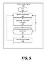
- FIG. 5illustrates an example method of initiating a fundus imaging using passive eye tracking.
- FIG. 1is a schematic block diagram illustrating an example system 100 for recording and viewing an image of a patient's fundus.
- the system 100includes a patient P, a fundus imaging system 102 , a camera 104 in communication 105 with an image processor 106 , a display 108 used by clinician C with the image processor 106 , and a network 110 .
- the fundus imaging system 102 and the display 108are in communication either directly via communication path 107 or via the network 110 using wired and/or wireless communication schemes.
- the fundus imaging system 102functions to create a digital image of a patient's P eye fundus.
- fundusrefers to the eye fundus and includes the retina, optic nerve, macula, vitreous, choroid and posterior pole.
- the patient Pin some embodiments, is being screened for an eye disease, such as diabetic retinopathy.
- the system 102can also be used to diagnose or monitor the progression of a disease such as diabetic retinopathy.
- the imaging system 102includes a handheld housing that supports the system's components.
- the housingsupports one or two apertures for imaging one or two eyes at a time.
- the housingsupports positional guides for the patient P, such as an adjustable chin rest. The positional guide or guides help to align the patient's P eye or eyes with the one or two apertures.
- the housingsupports means for raising and lowering the one or more apertures to align them with the patient's P eye or eyes. Once the patient's P eyes are aligned, the clinician C then initiates one or more image captures by the fundus imaging system 102 .
- Example system 100does not require a mydriatic drug to be administered to the patient P before imaging, although the system 100 can image the fundus if a mydriatic drug has been administered.
- the system 100is used to assist the clinician C in screening for, monitoring, or diagnosing various eye diseases.
- the clinician C that operates the fundus imaging system 102is different from the clinician C evaluating the resulting image.
- the fundus imaging system 102includes a camera 104 in communication 105 with an image processor 106 .
- the camera 104is a digital camera including a lens, an aperture, processor and a sensor array.
- the camera 104has a sensor array equipped with a global shutter.
- the camera 104is configured to record an image the fundus of one eye at a time.
- the camera 104is configured to record an image of both eyes substantially simultaneously.
- the fundus imaging system 102can include two separate cameras, one for each eye.
- the image processor 106is operatively coupled to the camera 104 and configured to communicate with the network 110 and/or display 108 . In some embodiments, the image processor 106 regulates the operation of the camera 104 .
- An example image processoris shown in more detail in FIG. 2 , which is described further below.
- the fundus imaging system 102is also connected to a printer, not shown in FIG. 1 .
- the printercan be used to produce a physical copy of the one or more fundus images produced by the fundus imaging system 102 .
- the display 108is in communication with the fundus imaging system 102 directly 107 or via the network 110 .
- the display 108functions to reproduce the image produced by the fundus imaging system 102 in a size and format readable by the clinician C.
- the housingsupports the display 108 , which is embedded in the housing.
- the display 108is a separate component of example system 100 , and may have its own housing, such as, for example, a monitor or a display on a mobile phone or tablet computer.
- the display 108is optional and the fundus imaging system 102 is connected to a cloud storage through network 110 . In that embodiment, the fundus imaging system 102 transmits the one or more fundus images to the cloud storage and the images can be viewed by accessing the cloud storage.
- the fundus imaging systemis connected to the network 110 (connection 101 ).
- the network 110is, in turn, connected to the display 108 (connection 103 ).
- the connections 101 and 103may include any type of wireless network, a wired network, or any communication network known in the art.
- wireless connectionscan include cellular network connections and connections made using protocols such as 802.11a, b, and/or g.
- a wireless connectioncan be accomplished directly between the fundus imaging system 102 and the display 108 using one or more wired or wireless protocols, such as Bluetooth, Wi-Fi Direct, radio-frequency identification (RFID), or Zigbee. Other configurations are possible.
- FIG. 2is a block diagram of the components in an example fundus imaging system 202 .
- the example fundus imaging system 202includes an image sensor array 204 that comprises monochrome photodiodes 206 , shutter control 208 , and opaque shielded storage 210 ; illumination unit 216 including light-emitting diode 218 and timing unit 220 ; computing system 222 including processor 224 and memory 226 ; lens 228 , an optional aperture 232 , networking unit 234 , and display 236 .
- the image sensor array 204 in the example system 202is a complementary metal-oxide semiconductor sensor array.
- the example sensor array 204includes monochrome photodiodes 206 , shutter control 208 , and opaque shielded storage 210 .
- the example sensor array 204functions to receive and process light reflected by the patient's fundus.
- the image sensor array 204has a plurality of rows of pixels and a plurality of columns of pixels. In some embodiments, the image sensor array has about 1280 by 1024 pixels, about 640 by 480 pixels, or about 1500 by 1152 pixels.
- the pixel size in the image sensor array 204is from about four micrometers by about four micrometers; from about two micrometers by about two micrometers; from about six micrometers by about six micrometers; or from about one micrometer by about one micrometer.
- the example monochrome photodiodes 206have a light-receiving surface and have substantially uniform length and width. During exposure, the monochrome photodiodes 206 convert the incident light to a charge.
- Shutter control 208 in example system 202initiates the exposure of the photodiodes 206 and the end of the exposure of the photodiodes 206 . In some embodiments, after the exposure period of the photodiodes 206 ends, the charge is transferred to opaque shielded storage 210 . Shutter control 208 also controls the reset of the photodiodes 206 and the read-out of the stored charges to be processed by computing system 222 .
- Shutter control 208is configured to operate the image sensor array 204 as a global shutter. That is, substantially all of the photodiodes are exposed simultaneously and for substantially identical lengths of time. The global exposure effectively integrates charge substantially evenly across the image sensor array 204 during the exposure time.
- a monochrome CMOS sensor with global reset modecan also be used without opaque shielded storage.
- the clinicianinitiates the exposure of the photodiodes 206 by global reset of all the pixels.
- the shutter control 208is configured to end the exposure period by global transferring all the pixels to their correspondent opaque shielded storages.
- shutter control 208ends the exposure period using a predetermined time period that starts when the clinician initiates an image capture sequence.
- an auto exposure control algorithmwill determine the exposure period dynamically according to the illumination conditions and/or image contrast.
- a Bayer filter, not used in example system 202essentially blocks out two-thirds of the light incident on the image sensor array.
- the monochrome photodiodes 206 used in the example system 202do not filter out light, which in turn improves the image quality.
- the example fundus imaging system 202advantageously requires roughly one-third of the light required by a fundus imaging system that employs a Bayer filter array.
- the example fundus imaging system 202can improve diabetic retinopathy screening sensitivity by reducing the number of false negatives. That is, the example fundus imaging system 202 can detect much lower contrast, and thereby detect more abnormal features, that the Bayer array cannot because the Bayer array limits the amount of imaged contrast. Additionally, the example fundus imaging system 202 can also reduce diabetic retinopathy false positives because the system 202 can produce higher uniform image quality without the Bayer array demosaic artifacts.
- the illumination unit 216 in example fundus imaging system 202provides light to illuminate the fundus and coordinate the timing with the exposure of the image sensor array.
- the example illumination unitincludes light-emitting diode 218 and timing unit 220 .
- Example light-emitting diode 218is in operative communication with the computing system 222 and the timing unit 220 .
- Example light-emitting diode 218is a three-color light-emitting diode (LED), where the three colors are red, green, and blue.
- the light-emitting diode 218can be a three-channel RGB LED, where each die is capable of independent and tandem operation.
- more than one LED 218is used in the illumination unit 216 .
- the LEDshave a maximum standard current draw rating of, for example, 20 mA, but the LED can be overdriven to draw more current, for example 30 mA (at 150% of maximum standard current), 200% of maximum current, 300% of maximum current, and 500% of maximum current in a low duty cycle usage. Other maximum standard current draws are possible.
- the one or more LEDs 218are overdriven during the illumination period, which is controlled by timing unit 220 in example system 202 .
- the combination of overdriving the LEDs with the global shutter operationresults in a shorter exposure period.
- the shorter exposure periodin some embodiments, results in a sharper image.
- the shorter illumination periodresults in less contraction of the pupil, thereby reducing the need for pupil dilation.
- dim lightIn order to maintain the patient's P pupil size as large as possible without dilation, dim light must be used. In the imaging systems known in the art, this dim light requirement results in poorer image quality. For example, the image quality when a 16 ms LED illumination period is used is much better than when a 2 ms LED illumination period is used in the prior art systems. In some embodiments, the LED illumination period used in example system 202 are 2 ms, 3 ms, or 5 ms. The example fundus imaging system 202 advantageously uses a dimmer LED light and produces a higher quality image than those systems known in the art.
- Each die in the LED 218is capable of independent and tandem operation. For example, in one embodiment, three consecutive frames are captured by the image sensor array 204 . The first exposure occurs when the red die is illuminated, then the second exposure occurs when the green die is illuminated, and then third exposure occurs when the blue die is illuminated. The order of die illumination is different in other embodiments.
- An alternative embodimentcaptures three consecutive frames for the following color illuminations: red (red die on only), yellow (red and green dies on substantially simultaneously), and white (reed, green, and blue dies on substantially simultaneously). Again, the order of illumination color is different in other embodiments.
- the white illuminationall dies on
- a red imageonly red die on
- a yellow imagered and green dies on
- timing unit 220activates the illumination timing of, and light emitted from, light-emitting diode 218 .
- Timing unit 220is, in some embodiments, a separate component including a processor and memory that is operatively coupled to the computing system 222 and image sensor array 204 .
- timing unit 220is a computer program stored on the memory 226 and configured to be run by the processor 224 .
- Timing unit 220can be configured to illuminate the light-emitting diode 218 at a time just before the image sensor array 204 initiates a global shutter exposure and to cease illumination shortly after the global shutter exposure ends. In other embodiments, the timing unit 220 can be configured to illuminate the light-emitting diode 218 after the global shutter exposure begins and to cease illumination before the global shutter exposure ends. In another embodiment, the timing unit 220 can be configured to illuminate the light-emitting diode 218 with an overlap period of time with the global shutter exposure period of time. In some embodiments the timing unit is configured to cause the light-emitting diode 218 to pulse or produce a strobe-like light during the illumination period.
- the computing system 222includes a processor 224 communicatively connected to a memory 226 via a data bus.
- the processor 224can be any of a variety of types of programmable circuits capable of executing computer-readable instructions to perform various tasks, such as mathematical and communication tasks.
- the memory 226can include any of a variety of memory devices, such as using various types of computer-readable or computer storage media.
- a computer storage medium or computer-readable mediummay be any medium that can contain or store the program for use by or in connection with the instruction execution system, apparatus, or device. In the context of the present disclosure, a computer storage medium includes at least some tangible component, i.e., is not entirely consisting of transient or transitory signals
- the example system 202also includes a lens 228 supported by the housing. Some embodiments have more than one lens supported by the housing. For example, one lens is used to focus the light incident on the image sensor array 204 and another lens to focuses the light from the illumination unit 216 . Some embodiments use more than one lens to focus the incident light.
- the lenshas mechanical power and control connections coupled to the computing system 222 .
- the computing system 222may be configured to control the position of the lens or lenses to optimize lens positioning for auto focusing for the image sensor array 204 and illumination unit 216 . In some embodiments, lens focusing is required in spite of a standard positioning guide for the patient because of unique facial geometries.
- the example fundus imaging system 202has, optionally, one or more apertures 232 supported by the housing.
- the aperture 232is an annular piece that supports a lens 228 .
- the patient's eyeis aligned substantially with the aperture 232 before the fundus is imaged.
- the apertureis a mechanically operated cover that can be opened and closed based upon signals from the computing system 222 .
- the example fundus imaging system 202has a display 236 for the clinician to focus and examine the patient's eye fundus.
- the imaging system 202has a networking unit 234 .
- Networking unitoperates to enable communication between the fundus imaging system 202 and the example display 108 or other networked devices.
- the networking unit 234may be in wireless or wired communication with the display 108 or other networked devices.
- the networking unit 234is in communication with the network 110 . In some embodiments, the networking unit 234 communicates with the display 108 over a wired or wireless connection.
- the fundus imaging system 202also includes an anti-aliasing filter, not pictured in FIG. 2 .
- the optional anti-aliasing filteris in some embodiments an optical low-pass filter. This filter is a thin layer located between the monochrome photodiodes 206 and the direction from which the incident light emanates. The filter, in some embodiments, prevents the occurrence of a pattern (moir é or other artifacts) different from the original image.
- the fundus imaging system 202also includes reflective mirrors, not shown in FIG. 2 .
- the optional one or more reflective mirrorsare used to direct light to the image sensor array 204 and from the illumination unit 216 .
- the one or more mirrorsare supported by, and fixed to, the housing.
- the reflective mirror or mirrorsare supported by the housing but have adjustable positions, where the clinician or computing system 222 can adjust the positioning of the mirrors.
- the example systemis operable without reflective mirrors.
- FIG. 3is a block flow diagram of an example use 300 by a clinician of the example fundus imaging system.
- Example use 300is performed in some embodiments by more than one clinician.
- Example use 300includes positioning a patient 302 , adjusting the focus 304 , initiating a retinal imaging 306 , and viewing the image 308 created by the scan.
- Other embodimentsmay omit steps or include additional steps.
- Example use 300begins when the clinician positions a patient 302 .
- the patientmay be seated or standing.
- Positioning 302includes aligning the patient such that one or more of the patient's eyes are aligned with the aperture or apertures of the fundus imaging system.
- the display coupled to the imaging systemshows a preview image to help guide the clinician in positioning the patient.
- the systememits an audible sound to notify the clinician that the patient's eye is in a proper position.
- a positioning structuresuch as a chin rest or head support structure, to assist in positioning the patient.
- the positioning structurehas means for adjustment that can be used by the clinician in positioning the patient's eye relative to the housing.
- the positioning structureis fixed and the housing has adjustment means such that the clinician can reposition the housing to be in alignment with the patient's eye or eyes.
- the next step in example use 300is for the clinician to adjust the focus 304 on the fundus imaging system.
- the fundus imaging systemhas one or more adjustable foci. These foci may be manually adjusted by the clinician, electronically adjusted by the clinician, or automatically adjusted by the fundus imaging system.
- the focusadjusts the position of the lens through which the incident light passes.
- the focusadjusts the lens through which the light from the illumination unit passes.
- the clinicianinitiates the automatic focusing by the fundus imaging system by pressing a button or selecting an icon on a graphical user interface.
- the adjust focus step 304can be replaced by auto focusing algorithms without human intervention.
- the clinicianinitiates the retinal imaging 306 in example use 300 .
- the clinicianinitiates the retinal imaging 306 by pressing a button or selecting an icon on a graphical user interface.
- An example of the fundus imaging system's steps during retinal imaging 306is shown in FIG. 4 and described in detail below.
- the clinicianmay return to step 302 to reposition the patient's other eye for imaging and repeat steps 304 and 306 .
- the clinicianmay view the image 308 , and may ensure that the image is of acceptable quality, before returning to step 302 to image the patient's other eye.
- initiate retinal imaging 306is replaced by passive eye tracking algorithms to automatically trigger the image capture without human intervention. Passive eye tracking is described with reference to FIG. 5 below.
- the clinicianviews the fundus image 308 in example use 300 . If any image is not satisfactory to the clinician, the clinician may repeat example use 300 . Examples of the types of displays that may be used in step 308 are described in more detail with reference to block 108 in FIG. 1 .
- FIG. 4illustrates a block flow diagram of an example method of operation 400 of the fundus imaging system.
- Example operation 400includes the fundus imaging system performing the steps of open aperture 402 , adjust focus on retina 404 , illuminate light-emitting diode 406 , which includes illuminate red light-emitting die 408 , illuminate green light-emitting die 410 , and illuminate blue light-emitting die 412 , control global shutter 414 , which includes global reset 416 , global transfer 418 , sequential readout of photodiodes 420 , store image read from photodiodes 422 , optionally returning to the illuminate light-emitting diode step 406 , process image read from photodiodes 426 , send processed image to display 428 , and send initial diagnosis to display 430 . Alternate embodiments may have fewer or additional steps, or perform the steps in a different order.
- the first stepis to, optionally, open aperture 402 .
- the aperturecan be a cover opened and closed through electrical or mechanical means.
- the apertureis a frame that, in some embodiments, supports a lens but does not have an operable cover.
- One purpose of the open aperture step 402is to enable incident light to pass through one or more lenses towards the image sensor array.
- Adjust focus on the retina 404is the next step in example operation 400 .
- the clinician operating the fundus imaging systemmanually changes one or more focal lengths. Adjusting the focus can be accomplished by, for example, mechanical means such as a knob or knobs or through electrical means such as a graphical user interface displaying focus adjustment parameters, where the interface is operatively coupled to adjustment means that is coupled to the one or more lenses. Adjusting the focus can also be accomplished automatically by auto focusing algorithms controlling a mechanical means without human intervention.
- the next step in example operation 400is to illuminate the light-emitting diode 406 .
- the illuminate light-emitting diode step 406comprises illuminating one or more of the colored dies in the red-green-blue light-emitting diode: illuminate the red die in the diode 408 , illuminate the green die in the diode 410 , and illuminate the blue die in the light-emitting diode 412 .
- Other combinations of colorsare possible, including, for example, cyan-magenta-yellow, red-green only or white-red only.
- the imaging systemhave more than one light-emitting diode. Additionally, in some embodiments of operation 400 , the illuminate step 406 occurs either after or concurrently with the global reset step 416 . The illuminate step 406 is performed multiple times, consecutively, in some embodiments.
- one imageis taken with all three dies illuminated 408 , 410 , and 412 , producing white light.
- the systeminitiates four consecutive image captures.
- the illumination unitis configured to produce white light for the first image capture, then red, green, and blue for the subsequent image captures. Other sequences in other embodiments are described in more detail with reference to illumination unit 216 in FIG. 2 .
- the light-emitting diodesare illuminated 406 for a short period of time.
- the diode, or diodesare illuminated for less than 5 milliseconds, for less than 2 milliseconds, for less than 1 millisecond, or for less than 0.5 milliseconds.
- the light-emitting diodemay be overdriven for some or all illuminations.
- One of many advantages of the example embodimentsis that the intensity, or the period, of the light-emitting diodes can be reduced by from about 5 to about 200 times those imaging systems in the art using a rolling shutter/reset CMOS sensor.
- Control global shutter step 414includes the global reset step 416 , the global transfer step 418 , and sequential readout step 420 .
- the computing systemoperatively coupled to the image sensor array, controls the image sensor array's global shutter in example operation 400 .
- Global reset step 416involves, in some embodiments, resetting and exposing every pixel in the image sensor array substantially simultaneously.
- the exposure of the pixelsis as short as possible to avoid motion blur and to limit the amount of time the patient's pupils must be illuminated. In some embodiments the exposure time is about 2 milliseconds.
- Global transfer step 418involves, in some embodiments, simultaneously ceasing the exposure of every pixel in the image sensor array and transferring the charge from each pixel into the opaque shielded storage.
- An example global shutteris described in more detail with reference to image sensor array 204 in FIG. 2 , above.
- Sequential readout step 420 in example operation 400involves each pixel in the image sensor array being readout sequentially (one pixel after the other).
- the readout step 420is accomplished, in some embodiments, by the computing system sending a readout clocking signal to the image sensor array to read out pixel value one by one.
- the pixel exposureis ended in example operation 400 and the image readout from the photodiodes' opaque shielded storage unit is stored 422 in memory.
- multiple imagesare captured consecutively and the example operation repeats 424 .
- Return step 424is shown in FIG. 4 as returning to step 406 , but in other embodiments the return step 424 begins by opening the aperture 402 or by adjusting the focus on the retina 404 step.
- the processorprocesses the image readout from the photodiodes' opaque shielded storage 426 in example operation 400 .
- processing of the imageis performed in accordance with a software program stored on the memory and run in the processor.
- processing 426includes amplifying the data generated from the incident light and converting the generated data into a digital signal. Processing 426 may also include storing a set of digital signal values corresponding to incident light on the plurality of pixels of image sensor array as a frame of image data. In some embodiments, the process image step 426 does not use color demosaic algorithms.
- Process image step 426includes a processor running image processing algorithms to, for example, perform image enhancement, perform features detection, and identify a classification to correct the diabetic retinopathy.
- the algorithmcan access an evaluation database for diabetic retinopathy such as DIARETDB0 and DIARETDB1, established by Lappeenrata University of Technology and University of Kuopio Medical Faculty in Finland. Those databases consist of about 219 fundus images that have been evaluated and annotated by experts and doctors to establish diagnosis results for those images.
- An example output of an evaluation algorithmwhen using a fundus image as an input, is that small red dots exist, there are hemorrhages and hard exudates are detected in the fundus.
- the outputcan identify both a list of the diagnoses and the number of observed issues.
- the outputcan also identify the detected issues on the fundus image, using, for example, graphics such as circles or arrows.
- the cliniciancan select the one or more issues the algorithm running on the processor should identify during processing step 426 .
- the clinicianselects through a graphical user interface “hemorrhages” in a menu containing possible diabetic retinopathy symptoms.
- the processed imagethen will contain identifying indicia such as on-screen arrows, circles or other identifying icons.
- the image in this embodimentcontains indicia flagging detected hemorrhages. But because, in this example, the clinician did not select any other symptoms, such as “exudates”, even if present, the image will not contain indicia flagging other symptoms.
- the processoris configured to detect all possible symptoms and the image contains indicia flagging all detected symptoms. Then, in some embodiments, the clinician uses a menu-type filter to select one or more symptoms to be flagged on the display.
- the image stored from the photodiode readoutis sent to a remote cloud storage and further processed, using algorithms described above, in a remote server.
- the computing systemsends the processed image to the display 428 and/or sends an initial diagnosis to display 430 .
- the systemproduces a raw image that does not contain any diagnostic identification information 428 .
- the systemproduces an image accompanied by diagnostic information 430 .
- FIG. 5illustrates an alternate embodiment of initiate retinal imaging step 306 using passive eye tracking.
- the initiate retinal imaging step 306operates to image the fundus of the patient P using passive eye tracking.
- the fundus imaging system 202monitors the pupil/fovea orientation of the patient P.
- the initiate retinal imaging step 306is described with respect to fundus imaging system 202 , the initiate retinal imaging step 306 may be performed using a wearable or nonwearable fundus imaging system, such as a handheld digital fundus imaging system.
- the pupil or fovea or both of the patient Pare monitored.
- the fundus imaging system 202captures images in a first image capture mode. In the first image capture mode, the fundus imaging system 202 captures images at a higher frame rate. In some embodiments, in the first image capture mode, the fundus imaging system 202 captures images with lower illumination and at lower resolutions.
- the lower illuminationis created by the illumination unit 216 operating to generate and direct light of a lower intensity towards the subject. In other embodiments, the lower illumination is created by an external light source or ambient light.
- the first image capture modemay minimize discomfort to the patient P, allow the patient P to relax, and allow for a larger pupil size without dilation (non-mydriatic).
- the computing system 222processes at least a portion of the images captured by the fundus imaging system 202 .
- the computing system 222processes the images to identify the location of the pupil or fovea or both of the patient P.
- a vector corresponding to the pupil/fovea orientationis calculated.
- the pupil/fovea orientationis approximated based on the distance between the pupil and fovea in the image.
- the pupil/fovea orientationis calculated by approximating the position of the fovea relative to the pupil in three dimensions using estimates of the distance to the pupil and the distance between the pupil and the fovea.
- the pupil/fovea orientationis approximated from the position of the pupil alone.
- other methods of approximating the pupil/fovea orientationare used.
- the pupil/fovea orientationis compared to the optical axis of the fundus imaging system 202 . If the pupil/fovea orientation is substantially aligned with the optical axis of the fundus imaging system 202 , the process proceeds to step 309 to capture a fundus image. If not, the process returns to step 303 to continue to monitor the pupil or fovea. In some embodiments, the pupil/fovea orientation is substantially aligned with the optical axis when the angle between them is less than two to fifteen degrees.
- a fundus imageis captured.
- the fundus imageis captured in a second image capture mode.
- the fundus imaging system 202captures images with higher illumination and at higher resolutions.
- the higher illuminationis created by the illumination unit 216 operating to generate and direct light of a higher intensity towards the subject.
- the higher illuminationis created by an external light source or ambient light.
- the second image capture modemay facilitate capturing a clear, well-illuminated, and detailed fundus image.
- the initiate retinal imaging step 306returns to step 303 to continue to monitor the pupil/fovea orientation.
- the initiate retinal imaging step 306may continue to collect fundus images indefinitely or until a specified number of images have been collected. Further information regarding passive eye tracking can be found in U.S. patent application Ser. No. 14/177,594, titled Ophthalmoscope Device, filed on even date herewith, which is hereby incorporated by reference in its entirety.
Landscapes
- Health & Medical Sciences (AREA)
- Life Sciences & Earth Sciences (AREA)
- Engineering & Computer Science (AREA)
- Medical Informatics (AREA)
- Surgery (AREA)
- Biophysics (AREA)
- Biomedical Technology (AREA)
- Heart & Thoracic Surgery (AREA)
- Physics & Mathematics (AREA)
- Molecular Biology (AREA)
- Ophthalmology & Optometry (AREA)
- Animal Behavior & Ethology (AREA)
- General Health & Medical Sciences (AREA)
- Public Health (AREA)
- Veterinary Medicine (AREA)
- Signal Processing (AREA)
- Eye Examination Apparatus (AREA)
Abstract
Description
Claims (15)
Priority Applications (1)
| Application Number | Priority Date | Filing Date | Title |
|---|---|---|---|
| US15/872,680US10376141B2 (en) | 2014-02-11 | 2018-01-16 | Fundus imaging system |
Applications Claiming Priority (4)
| Application Number | Priority Date | Filing Date | Title |
|---|---|---|---|
| US14/177,568US9211064B2 (en) | 2014-02-11 | 2014-02-11 | Fundus imaging system |
| US14/939,601US9498126B2 (en) | 2014-02-11 | 2015-11-12 | Fundus imaging system |
| US15/297,073US9918629B2 (en) | 2014-02-11 | 2016-10-18 | Fundus imaging system |
| US15/872,680US10376141B2 (en) | 2014-02-11 | 2018-01-16 | Fundus imaging system |
Related Parent Applications (1)
| Application Number | Title | Priority Date | Filing Date |
|---|---|---|---|
| US15/297,073ContinuationUS9918629B2 (en) | 2014-02-11 | 2016-10-18 | Fundus imaging system |
Publications (2)
| Publication Number | Publication Date |
|---|---|
| US20180140188A1 US20180140188A1 (en) | 2018-05-24 |
| US10376141B2true US10376141B2 (en) | 2019-08-13 |
Family
ID=53773874
Family Applications (4)
| Application Number | Title | Priority Date | Filing Date |
|---|---|---|---|
| US14/177,568Active2034-03-02US9211064B2 (en) | 2014-02-11 | 2014-02-11 | Fundus imaging system |
| US14/939,601ActiveUS9498126B2 (en) | 2014-02-11 | 2015-11-12 | Fundus imaging system |
| US15/297,073ActiveUS9918629B2 (en) | 2014-02-11 | 2016-10-18 | Fundus imaging system |
| US15/872,680ActiveUS10376141B2 (en) | 2014-02-11 | 2018-01-16 | Fundus imaging system |
Family Applications Before (3)
| Application Number | Title | Priority Date | Filing Date |
|---|---|---|---|
| US14/177,568Active2034-03-02US9211064B2 (en) | 2014-02-11 | 2014-02-11 | Fundus imaging system |
| US14/939,601ActiveUS9498126B2 (en) | 2014-02-11 | 2015-11-12 | Fundus imaging system |
| US15/297,073ActiveUS9918629B2 (en) | 2014-02-11 | 2016-10-18 | Fundus imaging system |
Country Status (5)
| Country | Link |
|---|---|
| US (4) | US9211064B2 (en) |
| EP (1) | EP3104766B1 (en) |
| CN (1) | CN106488738B (en) |
| AU (1) | AU2015217528B2 (en) |
| WO (1) | WO2015123028A1 (en) |
Cited By (5)
| Publication number | Priority date | Publication date | Assignee | Title |
|---|---|---|---|---|
| US10674907B2 (en) | 2014-02-11 | 2020-06-09 | Welch Allyn, Inc. | Opthalmoscope device |
| US10758119B2 (en) | 2015-07-24 | 2020-09-01 | Welch Allyn, Inc. | Automatic fundus image capture system |
| US10772495B2 (en) | 2015-11-02 | 2020-09-15 | Welch Allyn, Inc. | Retinal image capturing |
| US11045088B2 (en) | 2015-02-27 | 2021-06-29 | Welch Allyn, Inc. | Through focus retinal image capturing |
| US11096574B2 (en) | 2018-05-24 | 2021-08-24 | Welch Allyn, Inc. | Retinal image capturing |
Families Citing this family (27)
| Publication number | Priority date | Publication date | Assignee | Title |
|---|---|---|---|---|
| US20150021228A1 (en) | 2012-02-02 | 2015-01-22 | Visunex Medical Systems Co., Ltd. | Eye imaging apparatus and systems |
| US9351639B2 (en) | 2012-03-17 | 2016-05-31 | Visunex Medical Systems Co. Ltd. | Eye imaging apparatus with a wide field of view and related methods |
| EP3003124A4 (en) | 2013-05-31 | 2017-02-08 | The Board of Trustees of The Leland Stanford Junior University | Modular lens adapters for mobile anterior and posterior segment ophthalmoscopy |
| US9211064B2 (en) | 2014-02-11 | 2015-12-15 | Welch Allyn, Inc. | Fundus imaging system |
| US9986908B2 (en) | 2014-06-23 | 2018-06-05 | Visunex Medical Systems Co. Ltd. | Mechanical features of an eye imaging apparatus |
| US11372479B2 (en) | 2014-11-10 | 2022-06-28 | Irisvision, Inc. | Multi-modal vision enhancement system |
| US11546527B2 (en) | 2018-07-05 | 2023-01-03 | Irisvision, Inc. | Methods and apparatuses for compensating for retinitis pigmentosa |
| US10609270B2 (en) | 2014-11-18 | 2020-03-31 | The Invention Science Fund Ii, Llc | Devices, methods and systems for visual imaging arrays |
| US20180064335A1 (en)* | 2014-11-18 | 2018-03-08 | Elwha Llc | Retinal imager device and system with edge processing |
| CN107708524A (en) | 2015-01-26 | 2018-02-16 | 威盛纳斯医疗系统公司 | Disposable separation sleeve for eye imaging devices and associated method |
| US10799115B2 (en) | 2015-02-27 | 2020-10-13 | Welch Allyn, Inc. | Through focus retinal image capturing |
| WO2016154558A1 (en) | 2015-03-25 | 2016-09-29 | The Board Of Trustees Of The Leland Stanford Junior University | Modular adapters for mobile ophthalmoscopy |
| CN108475001B (en) | 2015-06-18 | 2021-06-11 | 爱丽丝视觉全球公司 | Adapter for retinal imaging using a handheld computer |
| WO2017120217A1 (en) | 2016-01-07 | 2017-07-13 | Welch Allyn, Inc. | Infrared fundus imaging system |
| US10464173B2 (en)* | 2016-06-02 | 2019-11-05 | Jiayuan Chen | Welding apparatus and method |
| US10602926B2 (en)* | 2016-09-29 | 2020-03-31 | Welch Allyn, Inc. | Through focus retinal image capturing |
| US10285589B2 (en) | 2016-09-30 | 2019-05-14 | Welch Allyn, Inc. | Fundus image capture system |
| CN107260121B (en)* | 2017-06-14 | 2023-11-21 | 苏州四海通仪器有限公司 | Compound eye fundus camera |
| US11045083B2 (en) | 2017-10-17 | 2021-06-29 | Verily Life Sciences Llc | Flash optimization during retinal burst imaging |
| US10708473B2 (en) | 2017-12-22 | 2020-07-07 | Verily Life Sciences Llc | Ocular imaging with illumination in image path |
| CN112534467A (en) | 2018-02-13 | 2021-03-19 | 弗兰克.沃布林 | Method and apparatus for contrast sensitivity compensation |
| US10582853B2 (en)* | 2018-03-13 | 2020-03-10 | Welch Allyn, Inc. | Selective illumination fundus imaging |
| US11389060B2 (en) | 2018-10-31 | 2022-07-19 | Verily Life Sciences Llc | Dynamic eye fixation for retinal imaging |
| US11571124B2 (en) | 2019-03-26 | 2023-02-07 | Verily Life Sciences Llc | Retinal imaging system with user-controlled fixation target for retinal alignment |
| US12369794B2 (en)* | 2020-08-10 | 2025-07-29 | Welch Allyn, Inc. | Microvascular assessment using eye imaging device |
| WO2023199088A1 (en)* | 2022-04-11 | 2023-10-19 | University Of Leeds | Determination of cardiac functional indices |
| US20250255481A1 (en)* | 2024-02-13 | 2025-08-14 | Identifeye Health Inc. | Adaptive structured illumination for ocular imaging |
Citations (190)
| Publication number | Priority date | Publication date | Assignee | Title |
|---|---|---|---|---|
| US5048946A (en) | 1990-05-15 | 1991-09-17 | Phoenix Laser Systems, Inc. | Spectral division of reflected light in complex optical diagnostic and therapeutic systems |
| US5557350A (en) | 1994-04-15 | 1996-09-17 | Nidek Co. Ltd. | Ophthalmometric apparatus with alignment device including filter means |
| US5599276A (en) | 1996-02-13 | 1997-02-04 | Welch Allyn, Inc. | Diopter value viewing means for a video ophthalmoscope |
| US5703621A (en) | 1994-04-28 | 1997-12-30 | Xerox Corporation | Universal display that presents all image types with high image fidelity |
| US5713047A (en) | 1992-06-08 | 1998-01-27 | Canon Kabushiki Kaisha | Eye fundus photographing apparatus |
| US5776060A (en) | 1997-02-20 | 1998-07-07 | University Of Alabama In Huntsville | Method and apparatus for measuring blood oxygen saturation within a retinal vessel with light having several selected wavelengths |
| US5784148A (en) | 1996-04-09 | 1998-07-21 | Heacock; Gregory Lee | Wide field of view scanning laser ophthalmoscope |
| US5943116A (en) | 1997-04-01 | 1999-08-24 | Johns Hopkins University | System for imaging an ocular fundus semi-automatically at high resolution and wide field |
| US6000799A (en) | 1998-05-01 | 1999-12-14 | Jozef F. Van De Velde | Maxwellian view and modulation control options for the scanning laser ophthalmoscope |
| US6011585A (en) | 1996-01-19 | 2000-01-04 | Apple Computer, Inc. | Apparatus and method for rotating the display orientation of a captured image |
| US6120461A (en) | 1999-08-09 | 2000-09-19 | The United States Of America As Represented By The Secretary Of The Army | Apparatus for tracking the human eye with a retinal scanning display, and method thereof |
| US6296358B1 (en) | 2000-07-14 | 2001-10-02 | Visual Pathways, Inc. | Ocular fundus auto imager |
| US6301440B1 (en) | 2000-04-13 | 2001-10-09 | International Business Machines Corp. | System and method for automatically setting image acquisition controls |
| US6307526B1 (en) | 1998-02-02 | 2001-10-23 | W. Steve G. Mann | Wearable camera system with viewfinder means |
| US6309070B1 (en) | 2000-09-06 | 2001-10-30 | Medibell Medical Vision Technologies, Ltd. | Integrated ophthalmic illumination method and system |
| US6325511B1 (en) | 1999-01-28 | 2001-12-04 | Kowa Company Ltd. | Ophthalmic photographic apparatus |
| US6350031B1 (en) | 1996-07-29 | 2002-02-26 | Kameran Lashkari | Electro-optic binocular indirect ophthalmoscope |
| US20020101568A1 (en) | 2001-01-30 | 2002-08-01 | Eberl Heinrich A. | Interactive data view and command system |
| US20030009155A1 (en) | 2000-05-12 | 2003-01-09 | Ceramoptec Industries, Inc. | Method for accurate optical treatment of an eye's fundus |
| GB2378600A (en) | 2001-08-06 | 2003-02-12 | Patrick Kerr | Retinal function camera to determine retinal blood oxygenation. |
| US20030071970A1 (en) | 2001-10-17 | 2003-04-17 | Carl Zeiss Meditec Ag | Ophthalmologic examination instrument |
| US6556853B1 (en) | 1995-12-12 | 2003-04-29 | Applied Spectral Imaging Ltd. | Spectral bio-imaging of the eye |
| US20030208125A1 (en) | 2002-04-09 | 2003-11-06 | Rodney Dennis Watkins | Fundus Camera |
| US6666857B2 (en) | 2002-01-29 | 2003-12-23 | Robert F. Smith | Integrated wavefront-directed topography-controlled photoablation |
| WO2004089214A2 (en) | 2003-04-11 | 2004-10-21 | Bausch & Lomb Inc. | System and method for acquiring data and aligning and tracking of an eye |
| US20050012899A1 (en) | 2002-06-14 | 2005-01-20 | Physical Sciences, Inc. | Line-scan laser ophthalmoscope |
| US20050043588A1 (en) | 1998-11-25 | 2005-02-24 | Jory Tsai | Medical inspection device |
| US20050110949A1 (en) | 2003-10-28 | 2005-05-26 | Welch Allyn, Inc. | Digital documenting ophthalmoscope |
| US20050254008A1 (en) | 2002-06-14 | 2005-11-17 | Ferguson R D | Monitoring blood flow in the retina using a line-scanning laser ophthalmoscope |
| WO2006016366A2 (en) | 2004-08-12 | 2006-02-16 | Elop Electro-Optical Industries Ltd. | Integrated retinal imager and method |
| JP2006101943A (en) | 2004-09-30 | 2006-04-20 | Nidek Co Ltd | Fundus camera |
| US20060113386A1 (en) | 2004-12-01 | 2006-06-01 | Psc Scanning, Inc. | Illumination pulsing method for a data reader |
| US20060119858A1 (en) | 2004-12-02 | 2006-06-08 | Knighton Robert W | Enhanced optical coherence tomography for anatomical mapping |
| US20060147095A1 (en) | 2005-01-03 | 2006-07-06 | Usher David B | Method and system for automatically capturing an image of a retina |
| US20060202038A1 (en) | 2005-03-11 | 2006-09-14 | Ynjiun Wang | System and method to automatically focus an image reader |
| US20060202036A1 (en) | 2005-03-11 | 2006-09-14 | Ynjiun Wang | Bar code reading device with global electronic shutter control |
| US7134754B2 (en) | 2001-04-09 | 2006-11-14 | Patrick Kerr | Retinal function camera |
| US20060268231A1 (en) | 2003-07-03 | 2006-11-30 | Medibell Medicall Vision Technologies, Ltd. | Illumination method and system for obtaining color images by transcleral ophthalmic illumination |
| US20070030450A1 (en) | 2005-08-03 | 2007-02-08 | Eastman Kodak Company | Automated fundus imaging system |
| US20070174095A1 (en) | 2006-01-20 | 2007-07-26 | Deer & Company, A Delaware Corporation | System and method for evaluating risk associated with a crop insurance policy |
| US20070174152A1 (en) | 2003-12-08 | 2007-07-26 | Bjornberg David B | Handheld system for information acquisition, verification, recording, processing, display and communication |
| US20070188706A1 (en) | 2006-01-27 | 2007-08-16 | Pearson Ken J | Fundus image display system |
| US7264355B2 (en) | 2002-12-16 | 2007-09-04 | Sis Ag Surgical Instrument Systems | Ophthalmologic device and ophthalmologic measuring method |
| US7311400B2 (en) | 2001-04-16 | 2007-12-25 | Tracey Technologies, Llc | Determining clinical refraction of eye |
| US20080084538A1 (en) | 2006-10-04 | 2008-04-10 | Naoyuki Maeda | Fundus oculi observation device, a fundus oculi image display device and a fundus oculi image display method |
| US7380938B2 (en) | 2003-03-25 | 2008-06-03 | Sarnoff Corporation | Apparatus to detect and measure saccade and pupilary changes |
| US7387384B2 (en) | 2005-05-02 | 2008-06-17 | Heine Optotechnik Gmbh & Co. Kg | Ophthalmoscope |
| US20080165322A1 (en) | 2007-01-10 | 2008-07-10 | Clarity Medical Systems, Inc. | Working distance and alignment sensor for a fundus camera |
| WO2008106802A1 (en) | 2007-03-08 | 2008-09-12 | University Of Northern British Columbia | Apparatus and method for objective perimetry visual field test |
| US20080231803A1 (en) | 2006-09-28 | 2008-09-25 | University Of Rochester | Compact ocular fundus camera |
| US20080316426A1 (en) | 2007-06-04 | 2008-12-25 | Nidek Co. Ltd. | Fundus camera |
| US7470024B2 (en) | 2006-06-12 | 2008-12-30 | Opto Eletronics S/A | System for obtaining a fundus image |
| US7488294B2 (en) | 2004-04-01 | 2009-02-10 | Torch William C | Biosensors, communicators, and controllers monitoring eye movement and methods for using them |
| US7502639B2 (en) | 2004-06-29 | 2009-03-10 | Patrick Kerr | Analysis of retinal metabolism over at least a portion of a cardiac cycle |
| US20090096885A1 (en) | 2007-10-08 | 2009-04-16 | Keymed (Medical & Industrial Equipment) Ltd | Electronic Camera |
| JP2009172157A (en) | 2008-01-24 | 2009-08-06 | Topcon Corp | Ophthalmological photographing apparatus |
| US20090225277A1 (en) | 2008-03-05 | 2009-09-10 | Tamir Gil | Snapshot Spectral Imaging of the Eye |
| JP2009219644A (en) | 2008-03-14 | 2009-10-01 | Nidek Co Ltd | Scanning fundus imaging apparatus |
| US20090275929A1 (en) | 2008-04-30 | 2009-11-05 | Amo Development, Llc | System and method for controlling measurement in an eye during ophthalmic procedure |
| US20090316115A1 (en) | 2008-03-28 | 2009-12-24 | Tatsuo Itoh | Image display apparatus and image display method |
| US20090323022A1 (en)* | 2008-06-26 | 2009-12-31 | Canon Kabushiki Kaisha | Medical imaging apparatus |
| US20090323023A1 (en) | 2005-03-31 | 2009-12-31 | Kabushiki Kaisha Topcon | Ophthalmologic Imager |
| US20100007849A1 (en) | 2006-07-07 | 2010-01-14 | Od-Os Gmbh | Ophthalmoscope |
| US20100014052A1 (en) | 2006-12-21 | 2010-01-21 | Ingo Koschmieder | Optical system for a fundus camera |
| JP2010057547A (en) | 2008-09-01 | 2010-03-18 | Canon Inc | Fundus camera |
| US20100085538A1 (en) | 2008-09-25 | 2010-04-08 | Canon Kabushiki Kaisha | Eye fundus camera |
| US20100110375A1 (en) | 2007-04-18 | 2010-05-06 | Kabushiki Kaisha Topcon | Optical image measurement device |
| US20100149489A1 (en) | 2007-05-23 | 2010-06-17 | Kabushiki Kaisha Topcon | Fundus oculi observation device and program for controlling the same |
| WO2010080576A1 (en) | 2008-12-19 | 2010-07-15 | University Of Miami | System and method for early detection of diabetic retinopathy using optical coherence tomography |
| US20100208961A1 (en) | 2006-12-11 | 2010-08-19 | Cytyc Corporation | Method for assessing image focus quality |
| US7784940B2 (en) | 1998-11-24 | 2010-08-31 | Welch Allyn, Inc. | Eye viewing device comprising video capture optics |
| US20100238402A1 (en) | 2009-03-19 | 2010-09-23 | Canon Kabushiki Kaisha | Fundus camera |
| US7809160B2 (en) | 2003-11-14 | 2010-10-05 | Queen's University At Kingston | Method and apparatus for calibration-free eye tracking using multiple glints or surface reflections |
| WO2010115195A1 (en) | 2009-04-03 | 2010-10-07 | Dyer Holdings, Llc | Infrared slit lamp ophthalmoscope |
| US20110001927A1 (en) | 2008-02-01 | 2011-01-06 | Linos Photonics Gmbh & Co., Kg | Fundus scanning apparatus |
| US7871164B2 (en) | 2006-02-28 | 2011-01-18 | Carl Zeiss Meditec Ag | Ophthalmological instrument |
| US20110028513A1 (en) | 2008-03-31 | 2011-02-03 | Lang Zhuo | Method for treating neurological disorders with imidazolium and imidazolinium compounds |
| US20110043756A1 (en) | 2008-04-22 | 2011-02-24 | Annidis Health Systems Corp. | Retinal fundus surveillance method and apparatus |
| WO2011029064A1 (en) | 2009-09-04 | 2011-03-10 | University Of Virginia Patent Foundation | Hand-held portable fundus camera for screening photography |
| US7926945B2 (en) | 2005-07-22 | 2011-04-19 | Carl Zeiss Meditec Ag | Device and method for monitoring, documenting and/or diagnosing the fundus |
| JP2011097992A (en) | 2009-11-04 | 2011-05-19 | Canon Inc | Fundus observation apparatus, fundus observation method, and computer program |
| US7963653B1 (en) | 2009-07-29 | 2011-06-21 | Eyequick, Llc | Digital imaging ophthalmoscope |
| US7976162B2 (en) | 2006-09-29 | 2011-07-12 | Daniel Ian Flitcroft | Eye examining system and method |
| US20110169935A1 (en) | 2008-10-15 | 2011-07-14 | Optibrand Ltd., Llc | Method and apparatus for obtaining an image of an ocular feature |
| US20110234977A1 (en) | 2010-03-23 | 2011-09-29 | Steven Roger Verdooner | Apparatus and method for imaging an eye |
| US20110242306A1 (en) | 2008-12-19 | 2011-10-06 | The Johns Hopkins University | System and method for automated detection of age related macular degeneration and other retinal abnormalities |
| EP2374404A1 (en) | 2009-01-06 | 2011-10-12 | Kabushiki Kaisha TOPCON | Optical image measurement device and method for controlling same |
| US20110261184A1 (en) | 2008-10-17 | 2011-10-27 | Mason Michael S | Optical microscope methods and apparatuses |
| US20110299036A1 (en) | 2010-06-02 | 2011-12-08 | Goldenholz Daniel M | Portable digital direct ophthalmoscope |
| US20110299034A1 (en) | 2008-07-18 | 2011-12-08 | Doheny Eye Institute | Optical coherence tomography- based ophthalmic testing methods, devices and systems |
| US20120002167A1 (en) | 2010-07-05 | 2012-01-05 | Nidek Co., Ltd. | Ophthalmic apparatus |
| CN102324014A (en) | 2005-03-11 | 2012-01-18 | 手持产品公司 | Bar code reading device with global electronic shutter control |
| WO2012009702A1 (en) | 2010-07-15 | 2012-01-19 | Corinthian Ophthalmic, Inc. | Method and system for performing remote treatment and monitoring |
| US20120044456A1 (en) | 2009-04-30 | 2012-02-23 | Kabushiki Kaisha Topcon | Fundus observation apparatus |
| US20120050677A1 (en) | 2010-08-31 | 2012-03-01 | Canon Kabushiki Kaisha | Fundus imaging apparatus |
| US20120121158A1 (en) | 2009-07-29 | 2012-05-17 | Kabushiki Kaisha Topcon | Ophthalmic observation apparatus |
| US20120147327A1 (en) | 2009-08-27 | 2012-06-14 | Canon Kabushiki Kaisha | Ophthalmologic photographing apparatus and camera for use in ophthalmologic photographing |
| US20120169995A1 (en) | 2010-09-14 | 2012-07-05 | Carl Zeiss Meditec Ag | Method and device for producing high-quality fundus images |
| CN102626304A (en) | 2012-04-19 | 2012-08-08 | 重庆大学 | Head-mounted wireless video eye tracker |
| US20120200690A1 (en) | 2009-10-05 | 2012-08-09 | Keeler Limited | Ophthalmic instruments |
| US20120213423A1 (en) | 2009-05-29 | 2012-08-23 | University Of Pittsburgh -- Of The Commonwealth System Of Higher Education | Blood vessel segmentation with three dimensional spectral domain optical coherence tomography |
| US20120218301A1 (en) | 2010-02-28 | 2012-08-30 | Osterhout Group, Inc. | See-through display with an optical assembly including a wedge-shaped illumination system |
| US20120229764A1 (en) | 2011-03-10 | 2012-09-13 | Canon Kabushiki Kaisha | Ophthalmologic apparatus and control method of the same |
| US20120249956A1 (en) | 2011-03-30 | 2012-10-04 | Carl Zeiss Meditec, Inc. | Systems and methods for efficiently obtaining measurements of the human eye using tracking |
| US20120248196A1 (en) | 2005-06-03 | 2012-10-04 | Hand Held Products, Inc. | Apparatus having hybrid monochrome and color image sensor array |
| WO2012134272A1 (en) | 2011-03-25 | 2012-10-04 | L2G B.V. | Multifunctional apparatus and method for inspecting an eye |
| US20120257163A1 (en) | 2008-10-28 | 2012-10-11 | Dyer Holdings, Llc | Video Infrared Ophthalmoscope |
| US20120281874A1 (en) | 2011-05-05 | 2012-11-08 | Lure Yuan-Ming F | Method, material, and apparatus to improve acquisition of human frontal face images using image template |
| JP2012213575A (en) | 2011-04-01 | 2012-11-08 | Canon Inc | Ophthalmologic photographing apparatus |
| US20120320340A1 (en) | 2011-06-18 | 2012-12-20 | Intuitive Medical Technologies, Llc | Smart-phone adapter for ophthalmoscope |
| US8347106B2 (en) | 2007-07-03 | 2013-01-01 | Nds Limited | Method and apparatus for user authentication based on a user eye characteristic |
| KR20130001079A (en) | 2011-06-24 | 2013-01-03 | 헤스본주식회사 | Hydraulic cylinder tuning apparatus for car lifting |
| US20130002711A1 (en) | 2010-03-31 | 2013-01-03 | Canon Kabushiki Kaisha | Image processing apparatus, oct imaging apparatus, tomographic imaging system, control method, and program |
| US20130010260A1 (en) | 2011-07-08 | 2013-01-10 | Carl Zeiss Meditec, Inc. | Light field camera for fundus photography |
| US20130016320A1 (en) | 2011-07-14 | 2013-01-17 | Canon Kabushiki Kaisha | Imaging control apparatus, ophthalmic imaging apparatus, imaging control method, and program |
| US8366270B2 (en) | 2008-04-30 | 2013-02-05 | Universitat Politecnica De Catalunya | Method and system for the objective measurement of ocular accommodation |
| US20130033593A1 (en) | 2009-10-14 | 2013-02-07 | Chinnock Randal B | Portable Retinal Camera and Image Acquisition Method |
| US8388523B2 (en) | 2005-04-01 | 2013-03-05 | Welch Allyn, Inc. | Medical diagnostic instrument having portable illuminator |
| US20130057828A1 (en) | 2009-08-31 | 2013-03-07 | Marc De Smet | Handheld portable fundus imaging system and method |
| JP2013046850A (en) | 2012-12-04 | 2013-03-07 | Canon Inc | Fundus camera |
| US20130063698A1 (en) | 2011-09-14 | 2013-03-14 | Kabushiki Kaisha Topcon | Fundus observation apparatus |
| WO2013041658A1 (en) | 2011-09-23 | 2013-03-28 | Carl Zeiss Ag | Appliance and method for recording an image of an ocular fundus |
| US20130128223A1 (en) | 2011-11-09 | 2013-05-23 | Wetch Allyn, Inc. | Digital-based medical devices |
| WO2013082387A1 (en) | 2011-12-02 | 2013-06-06 | Aguren Jerry G | Wide field-of-view 3d stereo vision platform with dynamic control of immersive or heads-up display operation |
| US20130162950A1 (en) | 2011-12-21 | 2013-06-27 | Canon Kabushiki Kaisha | Ophthalmologic apparatus and ophthalmologic control method, and program |
| US20130169934A1 (en) | 2011-12-09 | 2013-07-04 | Steven Roger Verdooner | Method for combining a plurality of eye images into a plenoptic multifocal image |
| US20130176533A1 (en)* | 2012-01-06 | 2013-07-11 | Hayes Solos Raffle | Structured Light for Eye-Tracking |
| US8488895B2 (en) | 2006-05-31 | 2013-07-16 | Indiana University Research And Technology Corp. | Laser scanning digital camera with pupil periphery illumination and potential for multiply scattered light imaging |
| WO2013107464A1 (en) | 2012-01-19 | 2013-07-25 | Daif Mohammad Abdelfattah | Corneal visual center localizer (or locator) |
| US20130194548A1 (en) | 2011-04-07 | 2013-08-01 | Raytheon Company | Portable retinal imaging device |
| US20130201449A1 (en) | 2008-03-27 | 2013-08-08 | Doheny Eye Institute | Optical coherence tomography device, method, and system |
| US20130211285A1 (en) | 2011-12-02 | 2013-08-15 | Terry A. Fuller | Devices and Methods for Noninvasive Measurement of Intracranial Pressure |
| US20130208241A1 (en) | 2012-02-13 | 2013-08-15 | Matthew Everett Lawson | Methods and Apparatus for Retinal Imaging |
| US20130215387A1 (en) | 2012-02-21 | 2013-08-22 | Canon Kabushiki Kaisha | Fundus imaging apparatus and method |
| US20130222763A1 (en) | 2010-11-06 | 2013-08-29 | Carl Zeiss Meditec Ag | Fundus camera with strip-shaped pupil division, and method for recording artifact-free, high-resolution fundus images |
| US20130229622A1 (en) | 2012-03-02 | 2013-09-05 | Nidek Co., Ltd. | Ophthalmologic photographing apparatus and ophthalmologic photographing method |
| US20130234930A1 (en) | 2012-03-07 | 2013-09-12 | Julian Palacios Goerger | Scanning mirror laser and projector head-up display glasses |
| US8534837B2 (en) | 2009-05-01 | 2013-09-17 | Bioptigen, Inc. | Systems for imaging structures of a subject and related methods |
| US20130250237A1 (en) | 2005-10-31 | 2013-09-26 | Nidek Co., Ltd. | Ophthalmic photographing apparatus |
| US20130250242A1 (en) | 2012-03-21 | 2013-09-26 | Optovue, Inc. | Fundus camera |
| US8577644B1 (en) | 2013-03-11 | 2013-11-05 | Cypress Semiconductor Corp. | Hard press rejection |
| US20130301004A1 (en) | 2008-04-22 | 2013-11-14 | Annidis Health Systems Corp. | Retinal fundus surveillance method and apparatus |
| US8585203B2 (en) | 2009-05-22 | 2013-11-19 | Canon Kabushiki Kaisha | Ophthalmologic photographing apparatus |
| US8620048B2 (en) | 2010-03-19 | 2013-12-31 | Canon Kabushiki Kaisha | Image processing apparatus, image processing system, image processing method, and image processing computer program |
| US20140022270A1 (en) | 2012-07-18 | 2014-01-23 | Optos Public Limited Company | Alignment Apparatus |
| US8649008B2 (en) | 2010-02-04 | 2014-02-11 | University Of Southern California | Combined spectral and polarimetry imaging and diagnostics |
| US8696122B2 (en) | 2010-01-21 | 2014-04-15 | Physical Sciences, Inc. | Multi-functional adaptive optics retinal imaging |
| US20140104573A1 (en) | 2010-06-01 | 2014-04-17 | Canon Kabshiki Kaisha | Ophthalmic imaging apparatus and control method thereof |
| US20140111773A1 (en) | 2012-10-18 | 2014-04-24 | Canon Kabushiki Kaisha | Ophthalmologic apparatus, ophthalmologic control method, and program |
| US20140118693A1 (en) | 2012-10-26 | 2014-05-01 | Canon Kabushiki Kaisha | Ophthalmologic apparatus, control method thereof, and program |
| US20140118697A1 (en) | 2012-10-26 | 2014-05-01 | Canon Kabushiki Kaisha | Ophthalmologic apparatus and method for controlling the same |
| US20140192320A1 (en) | 2013-01-08 | 2014-07-10 | Altek Corporation | Image capturing apparatus and capturing method |
| US20140198298A1 (en) | 2013-01-14 | 2014-07-17 | Altek Corporation | Image stitching method and camera system |
| US20140204341A1 (en) | 2013-01-23 | 2014-07-24 | Nidek Co., Ltd. | Ophthalmic imaging apparatus |
| US20140211162A1 (en) | 2013-01-31 | 2014-07-31 | Canon Kabushiki Kaisha | Ophthalmologic apparatus and method for controlling the same |
| US20140268046A1 (en) | 2013-03-14 | 2014-09-18 | Carl Zeiss Meditec, Inc. | Systems and methods for improved acquisition of ophthalmic optical coherence tomography data |
| US8879813B1 (en) | 2013-10-22 | 2014-11-04 | Eyenuk, Inc. | Systems and methods for automated interest region detection in retinal images |
| US20140330352A1 (en) | 2012-05-25 | 2014-11-06 | Ojai Retinal Technology, Llc | Apparatus for retina phototherapy |
| WO2014182769A1 (en) | 2013-05-07 | 2014-11-13 | The Johns Hopkins University | Automated and non-mydriatic fundus-perimetry camera for irreversible eye diseases |
| US20150002811A1 (en) | 2013-06-28 | 2015-01-01 | Canon Kabushiki Kaisha | Image processing apparatus and image processing method |
| US20150009357A1 (en) | 2012-02-16 | 2015-01-08 | University Of Washington Through Its Center For Commercialization | Extended depth of focus for high-resolution optical image scanning |
| WO2015044366A1 (en) | 2013-09-30 | 2015-04-02 | Carl Zeiss Meditec Ag | High temporal resolution doppler oct imaging of retinal blood flow |
| US20150150449A1 (en) | 2013-11-29 | 2015-06-04 | Canon Kabushiki Kaisha | Ophthalmologic apparatus and method of controlling the same |
| US20150170360A1 (en) | 2013-12-18 | 2015-06-18 | Canon Kabushiki Kaisha | Ophthalmic reference image selection |
| US20150178946A1 (en) | 2013-12-19 | 2015-06-25 | Google Inc. | Image adjustment using texture mask |
| US20150272434A1 (en) | 2014-03-31 | 2015-10-01 | Nidek Co., Ltd. | Fundus photography device |
| WO2015170947A1 (en) | 2014-05-09 | 2015-11-12 | (주)루트로닉 | Ophthalmic treatment device |
| US20150342459A1 (en) | 2014-05-29 | 2015-12-03 | Kabushiki Kaisha Topcon | Ophthalmologic apparatus |
| US9211064B2 (en) | 2014-02-11 | 2015-12-15 | Welch Allyn, Inc. | Fundus imaging system |
| US20160007845A1 (en) | 2014-07-10 | 2016-01-14 | Canon Kabushiki Kaisha | Fundus imaging apparatus, aberration correction method, and storage medium |
| US9237847B2 (en) | 2014-02-11 | 2016-01-19 | Welch Allyn, Inc. | Ophthalmoscope device |
| CN205006859U (en) | 2015-03-14 | 2016-02-03 | 中国科学院苏州生物医学工程技术研究所 | Two mesh pupils comprehensive testing system of setting a camera |
| CN105433899A (en) | 2015-11-30 | 2016-03-30 | 中国科学院苏州生物医学工程技术研究所 | Pupil detection device |
| US20160092721A1 (en) | 2013-05-19 | 2016-03-31 | Commonwealth Scientific And Industrial Research Organization | A system and method for remote medical diagnosis |
| CN205181314U (en) | 2015-03-14 | 2016-04-27 | 中国科学院苏州生物医学工程技术研究所 | Portable pair of mesh pupil detection device |
| US20160166141A1 (en) | 2013-07-10 | 2016-06-16 | Commonwealth Scientific And Industrial Research Organisation | Quantifying a blood vessel reflection parameter of the retina |
| US20160188993A1 (en) | 2014-12-30 | 2016-06-30 | Kodak Alaris Inc. | System and method for measuring mobile document image quality |
| US20160213249A1 (en) | 2011-03-02 | 2016-07-28 | Brien Holden Vision Diagnostics | Ocular Fundus Imaging Systems, Devices and Methods |
| US20160249804A1 (en) | 2015-02-27 | 2016-09-01 | Welch Allyn, Inc. | Through Focus Retinal Image Capturing |
| US20160307341A1 (en) | 2015-04-15 | 2016-10-20 | Canon Kabushiki Kaisha | Image processing apparatus and method of operation of the same |
| US20170020389A1 (en) | 2015-07-24 | 2017-01-26 | Ynjiun Paul Wang | Automatic fundus image capture system |
| US20170119241A1 (en) | 2015-11-02 | 2017-05-04 | Welch Allyn, Inc. | Retinal image capturing |
| US20170161892A1 (en) | 2014-07-02 | 2017-06-08 | Si14 S.P.A. | A method for acquiring and processing images of an ocular fundus by means of a portable electronic device |
| US20170172675A1 (en) | 2014-03-19 | 2017-06-22 | Intuitive Surgical Operations, Inc. | Medical devices, systems, and methods using eye gaze tracking |
| US20170181625A1 (en) | 2015-12-28 | 2017-06-29 | Canon Kabushiki Kaisha | System and Method for Controlling a Fundus Imaging Apparatus |
| US20170196452A1 (en) | 2016-01-07 | 2017-07-13 | Welch Allyn, Inc. | Infrared Fundus Imaging System |
| US20170209044A1 (en) | 2014-07-18 | 2017-07-27 | Kabushiki Kaisha Topcon | Visual function testing device and visual function testing system |
| US20170316565A1 (en) | 2016-04-29 | 2017-11-02 | Carl Zeiss Meditec, Inc. | Montaging of wide-field fundus images |
| US20170311800A1 (en) | 2015-02-27 | 2017-11-02 | Welch Allyn, Inc. | Through Focus Retinal Image Capturing |
| US20180092530A1 (en) | 2016-09-30 | 2018-04-05 | Welch Allyn, Inc. | Fundus Image Capture System |
Family Cites Families (1)
| Publication number | Priority date | Publication date | Assignee | Title |
|---|---|---|---|---|
| US8278749B2 (en)* | 2009-01-30 | 2012-10-02 | Infineon Technologies Ag | Integrated antennas in wafer level package |
- 2014
- 2014-02-11USUS14/177,568patent/US9211064B2/enactiveActive
- 2015
- 2015-01-29AUAU2015217528Apatent/AU2015217528B2/enactiveActive
- 2015-01-29EPEP15749109.3Apatent/EP3104766B1/enactiveActive
- 2015-01-29CNCN201580019259.3Apatent/CN106488738B/enactiveActive
- 2015-01-29WOPCT/US2015/013542patent/WO2015123028A1/enactiveIP Right Grant
- 2015-11-12USUS14/939,601patent/US9498126B2/enactiveActive
- 2016
- 2016-10-18USUS15/297,073patent/US9918629B2/enactiveActive
- 2018
- 2018-01-16USUS15/872,680patent/US10376141B2/enactiveActive
Patent Citations (221)
| Publication number | Priority date | Publication date | Assignee | Title |
|---|---|---|---|---|
| US5048946A (en) | 1990-05-15 | 1991-09-17 | Phoenix Laser Systems, Inc. | Spectral division of reflected light in complex optical diagnostic and therapeutic systems |
| US5713047A (en) | 1992-06-08 | 1998-01-27 | Canon Kabushiki Kaisha | Eye fundus photographing apparatus |
| US5557350A (en) | 1994-04-15 | 1996-09-17 | Nidek Co. Ltd. | Ophthalmometric apparatus with alignment device including filter means |
| US5703621A (en) | 1994-04-28 | 1997-12-30 | Xerox Corporation | Universal display that presents all image types with high image fidelity |
| US6556853B1 (en) | 1995-12-12 | 2003-04-29 | Applied Spectral Imaging Ltd. | Spectral bio-imaging of the eye |
| US6011585A (en) | 1996-01-19 | 2000-01-04 | Apple Computer, Inc. | Apparatus and method for rotating the display orientation of a captured image |
| US5599276A (en) | 1996-02-13 | 1997-02-04 | Welch Allyn, Inc. | Diopter value viewing means for a video ophthalmoscope |
| US5784148A (en) | 1996-04-09 | 1998-07-21 | Heacock; Gregory Lee | Wide field of view scanning laser ophthalmoscope |
| US6350031B1 (en) | 1996-07-29 | 2002-02-26 | Kameran Lashkari | Electro-optic binocular indirect ophthalmoscope |
| US5776060A (en) | 1997-02-20 | 1998-07-07 | University Of Alabama In Huntsville | Method and apparatus for measuring blood oxygen saturation within a retinal vessel with light having several selected wavelengths |
| US5943116A (en) | 1997-04-01 | 1999-08-24 | Johns Hopkins University | System for imaging an ocular fundus semi-automatically at high resolution and wide field |
| US6307526B1 (en) | 1998-02-02 | 2001-10-23 | W. Steve G. Mann | Wearable camera system with viewfinder means |
| US6000799A (en) | 1998-05-01 | 1999-12-14 | Jozef F. Van De Velde | Maxwellian view and modulation control options for the scanning laser ophthalmoscope |
| US7784940B2 (en) | 1998-11-24 | 2010-08-31 | Welch Allyn, Inc. | Eye viewing device comprising video capture optics |
| US20050043588A1 (en) | 1998-11-25 | 2005-02-24 | Jory Tsai | Medical inspection device |
| US6325511B1 (en) | 1999-01-28 | 2001-12-04 | Kowa Company Ltd. | Ophthalmic photographic apparatus |
| US6120461A (en) | 1999-08-09 | 2000-09-19 | The United States Of America As Represented By The Secretary Of The Army | Apparatus for tracking the human eye with a retinal scanning display, and method thereof |
| US6301440B1 (en) | 2000-04-13 | 2001-10-09 | International Business Machines Corp. | System and method for automatically setting image acquisition controls |
| US20030009155A1 (en) | 2000-05-12 | 2003-01-09 | Ceramoptec Industries, Inc. | Method for accurate optical treatment of an eye's fundus |
| US6296358B1 (en) | 2000-07-14 | 2001-10-02 | Visual Pathways, Inc. | Ocular fundus auto imager |
| US6309070B1 (en) | 2000-09-06 | 2001-10-30 | Medibell Medical Vision Technologies, Ltd. | Integrated ophthalmic illumination method and system |
| US20020101568A1 (en) | 2001-01-30 | 2002-08-01 | Eberl Heinrich A. | Interactive data view and command system |
| US7134754B2 (en) | 2001-04-09 | 2006-11-14 | Patrick Kerr | Retinal function camera |
| US7311400B2 (en) | 2001-04-16 | 2007-12-25 | Tracey Technologies, Llc | Determining clinical refraction of eye |
| GB2378600A (en) | 2001-08-06 | 2003-02-12 | Patrick Kerr | Retinal function camera to determine retinal blood oxygenation. |
| US20030071970A1 (en) | 2001-10-17 | 2003-04-17 | Carl Zeiss Meditec Ag | Ophthalmologic examination instrument |
| US6666857B2 (en) | 2002-01-29 | 2003-12-23 | Robert F. Smith | Integrated wavefront-directed topography-controlled photoablation |
| US20030208125A1 (en) | 2002-04-09 | 2003-11-06 | Rodney Dennis Watkins | Fundus Camera |
| US7284859B2 (en) | 2002-06-14 | 2007-10-23 | Physical Sciences, Inc. | Line-scan laser ophthalmoscope |
| US20050254008A1 (en) | 2002-06-14 | 2005-11-17 | Ferguson R D | Monitoring blood flow in the retina using a line-scanning laser ophthalmoscope |
| US7404640B2 (en) | 2002-06-14 | 2008-07-29 | Physical Sciences, Inc. | Monitoring blood flow in the retina using a line-scanning laser ophthalmoscope |
| US20050012899A1 (en) | 2002-06-14 | 2005-01-20 | Physical Sciences, Inc. | Line-scan laser ophthalmoscope |
| US7264355B2 (en) | 2002-12-16 | 2007-09-04 | Sis Ag Surgical Instrument Systems | Ophthalmologic device and ophthalmologic measuring method |
| US7380938B2 (en) | 2003-03-25 | 2008-06-03 | Sarnoff Corporation | Apparatus to detect and measure saccade and pupilary changes |
| WO2004089214A2 (en) | 2003-04-11 | 2004-10-21 | Bausch & Lomb Inc. | System and method for acquiring data and aligning and tracking of an eye |
| US20060268231A1 (en) | 2003-07-03 | 2006-11-30 | Medibell Medicall Vision Technologies, Ltd. | Illumination method and system for obtaining color images by transcleral ophthalmic illumination |
| US7364297B2 (en) | 2003-10-28 | 2008-04-29 | Welch Allyn, Inc. | Digital documenting ophthalmoscope |
| US20050110949A1 (en) | 2003-10-28 | 2005-05-26 | Welch Allyn, Inc. | Digital documenting ophthalmoscope |
| US7809160B2 (en) | 2003-11-14 | 2010-10-05 | Queen's University At Kingston | Method and apparatus for calibration-free eye tracking using multiple glints or surface reflections |
| US20070174152A1 (en) | 2003-12-08 | 2007-07-26 | Bjornberg David B | Handheld system for information acquisition, verification, recording, processing, display and communication |
| US7488294B2 (en) | 2004-04-01 | 2009-02-10 | Torch William C | Biosensors, communicators, and controllers monitoring eye movement and methods for using them |
| US7502639B2 (en) | 2004-06-29 | 2009-03-10 | Patrick Kerr | Analysis of retinal metabolism over at least a portion of a cardiac cycle |
| US8109635B2 (en) | 2004-08-12 | 2012-02-07 | Ophthalmic Imaging Systems | Integrated retinal imager and method |
| WO2006016366A2 (en) | 2004-08-12 | 2006-02-16 | Elop Electro-Optical Industries Ltd. | Integrated retinal imager and method |
| JP2006101943A (en) | 2004-09-30 | 2006-04-20 | Nidek Co Ltd | Fundus camera |
| US20060113386A1 (en) | 2004-12-01 | 2006-06-01 | Psc Scanning, Inc. | Illumination pulsing method for a data reader |
| US20060119858A1 (en) | 2004-12-02 | 2006-06-08 | Knighton Robert W | Enhanced optical coherence tomography for anatomical mapping |
| US20060147095A1 (en) | 2005-01-03 | 2006-07-06 | Usher David B | Method and system for automatically capturing an image of a retina |
| CN102324014A (en) | 2005-03-11 | 2012-01-18 | 手持产品公司 | Bar code reading device with global electronic shutter control |
| US20060202036A1 (en) | 2005-03-11 | 2006-09-14 | Ynjiun Wang | Bar code reading device with global electronic shutter control |
| US20060202038A1 (en) | 2005-03-11 | 2006-09-14 | Ynjiun Wang | System and method to automatically focus an image reader |
| US7611060B2 (en) | 2005-03-11 | 2009-11-03 | Hand Held Products, Inc. | System and method to automatically focus an image reader |
| US7568628B2 (en) | 2005-03-11 | 2009-08-04 | Hand Held Products, Inc. | Bar code reading device with global electronic shutter control |
| US20090323023A1 (en) | 2005-03-31 | 2009-12-31 | Kabushiki Kaisha Topcon | Ophthalmologic Imager |
| US8388523B2 (en) | 2005-04-01 | 2013-03-05 | Welch Allyn, Inc. | Medical diagnostic instrument having portable illuminator |
| US7387384B2 (en) | 2005-05-02 | 2008-06-17 | Heine Optotechnik Gmbh & Co. Kg | Ophthalmoscope |
| US20120248196A1 (en) | 2005-06-03 | 2012-10-04 | Hand Held Products, Inc. | Apparatus having hybrid monochrome and color image sensor array |
| US7926945B2 (en) | 2005-07-22 | 2011-04-19 | Carl Zeiss Meditec Ag | Device and method for monitoring, documenting and/or diagnosing the fundus |
| US20070030450A1 (en) | 2005-08-03 | 2007-02-08 | Eastman Kodak Company | Automated fundus imaging system |
| US20130250237A1 (en) | 2005-10-31 | 2013-09-26 | Nidek Co., Ltd. | Ophthalmic photographing apparatus |
| US20070174095A1 (en) | 2006-01-20 | 2007-07-26 | Deer & Company, A Delaware Corporation | System and method for evaluating risk associated with a crop insurance policy |
| US20070188706A1 (en) | 2006-01-27 | 2007-08-16 | Pearson Ken J | Fundus image display system |
| US7871164B2 (en) | 2006-02-28 | 2011-01-18 | Carl Zeiss Meditec Ag | Ophthalmological instrument |
| US8488895B2 (en) | 2006-05-31 | 2013-07-16 | Indiana University Research And Technology Corp. | Laser scanning digital camera with pupil periphery illumination and potential for multiply scattered light imaging |
| US7470024B2 (en) | 2006-06-12 | 2008-12-30 | Opto Eletronics S/A | System for obtaining a fundus image |
| US20100007849A1 (en) | 2006-07-07 | 2010-01-14 | Od-Os Gmbh | Ophthalmoscope |
| US20080231803A1 (en) | 2006-09-28 | 2008-09-25 | University Of Rochester | Compact ocular fundus camera |
| US7976162B2 (en) | 2006-09-29 | 2011-07-12 | Daniel Ian Flitcroft | Eye examining system and method |
| US20080084538A1 (en) | 2006-10-04 | 2008-04-10 | Naoyuki Maeda | Fundus oculi observation device, a fundus oculi image display device and a fundus oculi image display method |
| US20100208961A1 (en) | 2006-12-11 | 2010-08-19 | Cytyc Corporation | Method for assessing image focus quality |
| US20100014052A1 (en) | 2006-12-21 | 2010-01-21 | Ingo Koschmieder | Optical system for a fundus camera |
| US7621636B2 (en) | 2007-01-10 | 2009-11-24 | Clarity Medical Systems, Inc. | Working distance and alignment sensor for a fundus camera |
| US20080165322A1 (en) | 2007-01-10 | 2008-07-10 | Clarity Medical Systems, Inc. | Working distance and alignment sensor for a fundus camera |
| WO2008106802A1 (en) | 2007-03-08 | 2008-09-12 | University Of Northern British Columbia | Apparatus and method for objective perimetry visual field test |
| US20100110375A1 (en) | 2007-04-18 | 2010-05-06 | Kabushiki Kaisha Topcon | Optical image measurement device |
| US20100149489A1 (en) | 2007-05-23 | 2010-06-17 | Kabushiki Kaisha Topcon | Fundus oculi observation device and program for controlling the same |
| US20080316426A1 (en) | 2007-06-04 | 2008-12-25 | Nidek Co. Ltd. | Fundus camera |
| US8347106B2 (en) | 2007-07-03 | 2013-01-01 | Nds Limited | Method and apparatus for user authentication based on a user eye characteristic |
| US20090096885A1 (en) | 2007-10-08 | 2009-04-16 | Keymed (Medical & Industrial Equipment) Ltd | Electronic Camera |
| JP2009172157A (en) | 2008-01-24 | 2009-08-06 | Topcon Corp | Ophthalmological photographing apparatus |
| US20110001927A1 (en) | 2008-02-01 | 2011-01-06 | Linos Photonics Gmbh & Co., Kg | Fundus scanning apparatus |
| US20090225277A1 (en) | 2008-03-05 | 2009-09-10 | Tamir Gil | Snapshot Spectral Imaging of the Eye |
| US8109634B2 (en) | 2008-03-05 | 2012-02-07 | Tamir Gil | Snapshot spectral imaging of the eye |
| JP2009219644A (en) | 2008-03-14 | 2009-10-01 | Nidek Co Ltd | Scanning fundus imaging apparatus |
| US20130201449A1 (en) | 2008-03-27 | 2013-08-08 | Doheny Eye Institute | Optical coherence tomography device, method, and system |
| US20090316115A1 (en) | 2008-03-28 | 2009-12-24 | Tatsuo Itoh | Image display apparatus and image display method |
| US20110028513A1 (en) | 2008-03-31 | 2011-02-03 | Lang Zhuo | Method for treating neurological disorders with imidazolium and imidazolinium compounds |
| US20130301004A1 (en) | 2008-04-22 | 2013-11-14 | Annidis Health Systems Corp. | Retinal fundus surveillance method and apparatus |
| US20110043756A1 (en) | 2008-04-22 | 2011-02-24 | Annidis Health Systems Corp. | Retinal fundus surveillance method and apparatus |
| US8366270B2 (en) | 2008-04-30 | 2013-02-05 | Universitat Politecnica De Catalunya | Method and system for the objective measurement of ocular accommodation |
| US20090275929A1 (en) | 2008-04-30 | 2009-11-05 | Amo Development, Llc | System and method for controlling measurement in an eye during ophthalmic procedure |
| US20090323022A1 (en)* | 2008-06-26 | 2009-12-31 | Canon Kabushiki Kaisha | Medical imaging apparatus |
| US20110299034A1 (en) | 2008-07-18 | 2011-12-08 | Doheny Eye Institute | Optical coherence tomography- based ophthalmic testing methods, devices and systems |
| JP2010057547A (en) | 2008-09-01 | 2010-03-18 | Canon Inc | Fundus camera |
| US20100085538A1 (en) | 2008-09-25 | 2010-04-08 | Canon Kabushiki Kaisha | Eye fundus camera |
| US20110169935A1 (en) | 2008-10-15 | 2011-07-14 | Optibrand Ltd., Llc | Method and apparatus for obtaining an image of an ocular feature |
| US20110261184A1 (en) | 2008-10-17 | 2011-10-27 | Mason Michael S | Optical microscope methods and apparatuses |
| US20120257163A1 (en) | 2008-10-28 | 2012-10-11 | Dyer Holdings, Llc | Video Infrared Ophthalmoscope |
| WO2010080576A1 (en) | 2008-12-19 | 2010-07-15 | University Of Miami | System and method for early detection of diabetic retinopathy using optical coherence tomography |
| US20110242306A1 (en) | 2008-12-19 | 2011-10-06 | The Johns Hopkins University | System and method for automated detection of age related macular degeneration and other retinal abnormalities |
| EP2374404A1 (en) | 2009-01-06 | 2011-10-12 | Kabushiki Kaisha TOPCON | Optical image measurement device and method for controlling same |
| US20100238402A1 (en) | 2009-03-19 | 2010-09-23 | Canon Kabushiki Kaisha | Fundus camera |
| WO2010115195A1 (en) | 2009-04-03 | 2010-10-07 | Dyer Holdings, Llc | Infrared slit lamp ophthalmoscope |
| US20120044456A1 (en) | 2009-04-30 | 2012-02-23 | Kabushiki Kaisha Topcon | Fundus observation apparatus |
| EP2425763A1 (en) | 2009-04-30 | 2012-03-07 | Kabushiki Kaisha TOPCON | Eyeground observation device |
| US8534837B2 (en) | 2009-05-01 | 2013-09-17 | Bioptigen, Inc. | Systems for imaging structures of a subject and related methods |
| US8585203B2 (en) | 2009-05-22 | 2013-11-19 | Canon Kabushiki Kaisha | Ophthalmologic photographing apparatus |
| US20120213423A1 (en) | 2009-05-29 | 2012-08-23 | University Of Pittsburgh -- Of The Commonwealth System Of Higher Education | Blood vessel segmentation with three dimensional spectral domain optical coherence tomography |
| US7963653B1 (en) | 2009-07-29 | 2011-06-21 | Eyequick, Llc | Digital imaging ophthalmoscope |
| US20120121158A1 (en) | 2009-07-29 | 2012-05-17 | Kabushiki Kaisha Topcon | Ophthalmic observation apparatus |
| US8444269B1 (en) | 2009-07-29 | 2013-05-21 | Eyequick, Llc | Digital imaging ophthalmoscope |
| US20120147327A1 (en) | 2009-08-27 | 2012-06-14 | Canon Kabushiki Kaisha | Ophthalmologic photographing apparatus and camera for use in ophthalmologic photographing |
| US20130057828A1 (en) | 2009-08-31 | 2013-03-07 | Marc De Smet | Handheld portable fundus imaging system and method |
| US20120229617A1 (en) | 2009-09-04 | 2012-09-13 | University Of Virginia Patent Foundation | Hand-held portable fundus camera for screening photography |
| WO2011029064A1 (en) | 2009-09-04 | 2011-03-10 | University Of Virginia Patent Foundation | Hand-held portable fundus camera for screening photography |
| US20120200690A1 (en) | 2009-10-05 | 2012-08-09 | Keeler Limited | Ophthalmic instruments |
| US20130033593A1 (en) | 2009-10-14 | 2013-02-07 | Chinnock Randal B | Portable Retinal Camera and Image Acquisition Method |
| JP2011097992A (en) | 2009-11-04 | 2011-05-19 | Canon Inc | Fundus observation apparatus, fundus observation method, and computer program |
| US8696122B2 (en) | 2010-01-21 | 2014-04-15 | Physical Sciences, Inc. | Multi-functional adaptive optics retinal imaging |
| US8649008B2 (en) | 2010-02-04 | 2014-02-11 | University Of Southern California | Combined spectral and polarimetry imaging and diagnostics |
| US20120218301A1 (en) | 2010-02-28 | 2012-08-30 | Osterhout Group, Inc. | See-through display with an optical assembly including a wedge-shaped illumination system |
| US8620048B2 (en) | 2010-03-19 | 2013-12-31 | Canon Kabushiki Kaisha | Image processing apparatus, image processing system, image processing method, and image processing computer program |
| CN102917634A (en) | 2010-03-23 | 2013-02-06 | 神经视觉成像有限责任公司 | Apparatus and method for imaging an eye |
| US8714743B2 (en) | 2010-03-23 | 2014-05-06 | Steven Roger Verdooner | Apparatus and method for imaging an eye |
| US20140204340A1 (en) | 2010-03-23 | 2014-07-24 | Steven Roger Verdooner | Apparatus for imaging an eye |
| US20110234977A1 (en) | 2010-03-23 | 2011-09-29 | Steven Roger Verdooner | Apparatus and method for imaging an eye |
| US20130002711A1 (en) | 2010-03-31 | 2013-01-03 | Canon Kabushiki Kaisha | Image processing apparatus, oct imaging apparatus, tomographic imaging system, control method, and program |
| US20140104573A1 (en) | 2010-06-01 | 2014-04-17 | Canon Kabshiki Kaisha | Ophthalmic imaging apparatus and control method thereof |
| US20110299036A1 (en) | 2010-06-02 | 2011-12-08 | Goldenholz Daniel M | Portable digital direct ophthalmoscope |
| US20120002167A1 (en) | 2010-07-05 | 2012-01-05 | Nidek Co., Ltd. | Ophthalmic apparatus |
| WO2012009702A1 (en) | 2010-07-15 | 2012-01-19 | Corinthian Ophthalmic, Inc. | Method and system for performing remote treatment and monitoring |
| US20120050677A1 (en) | 2010-08-31 | 2012-03-01 | Canon Kabushiki Kaisha | Fundus imaging apparatus |
| US20120169995A1 (en) | 2010-09-14 | 2012-07-05 | Carl Zeiss Meditec Ag | Method and device for producing high-quality fundus images |
| US20130222763A1 (en) | 2010-11-06 | 2013-08-29 | Carl Zeiss Meditec Ag | Fundus camera with strip-shaped pupil division, and method for recording artifact-free, high-resolution fundus images |
| US20160213249A1 (en) | 2011-03-02 | 2016-07-28 | Brien Holden Vision Diagnostics | Ocular Fundus Imaging Systems, Devices and Methods |
| US20120229764A1 (en) | 2011-03-10 | 2012-09-13 | Canon Kabushiki Kaisha | Ophthalmologic apparatus and control method of the same |
| WO2012134272A1 (en) | 2011-03-25 | 2012-10-04 | L2G B.V. | Multifunctional apparatus and method for inspecting an eye |
| US20120249956A1 (en) | 2011-03-30 | 2012-10-04 | Carl Zeiss Meditec, Inc. | Systems and methods for efficiently obtaining measurements of the human eye using tracking |
| JP2012213575A (en) | 2011-04-01 | 2012-11-08 | Canon Inc | Ophthalmologic photographing apparatus |
| US20130194548A1 (en) | 2011-04-07 | 2013-08-01 | Raytheon Company | Portable retinal imaging device |
| US20120281874A1 (en) | 2011-05-05 | 2012-11-08 | Lure Yuan-Ming F | Method, material, and apparatus to improve acquisition of human frontal face images using image template |
| US20120320340A1 (en) | 2011-06-18 | 2012-12-20 | Intuitive Medical Technologies, Llc | Smart-phone adapter for ophthalmoscope |
| KR20130001079A (en) | 2011-06-24 | 2013-01-03 | 헤스본주식회사 | Hydraulic cylinder tuning apparatus for car lifting |
| US20130010260A1 (en) | 2011-07-08 | 2013-01-10 | Carl Zeiss Meditec, Inc. | Light field camera for fundus photography |
| US20130016320A1 (en) | 2011-07-14 | 2013-01-17 | Canon Kabushiki Kaisha | Imaging control apparatus, ophthalmic imaging apparatus, imaging control method, and program |
| US20130063698A1 (en) | 2011-09-14 | 2013-03-14 | Kabushiki Kaisha Topcon | Fundus observation apparatus |
| JP2013059551A (en) | 2011-09-14 | 2013-04-04 | Topcon Corp | Fundus observation apparatus |
| WO2013041658A1 (en) | 2011-09-23 | 2013-03-28 | Carl Zeiss Ag | Appliance and method for recording an image of an ocular fundus |
| US20170239012A1 (en) | 2011-11-09 | 2017-08-24 | Welch Allyn, Inc. | Digital-based medical devices |
| US20130128223A1 (en) | 2011-11-09 | 2013-05-23 | Wetch Allyn, Inc. | Digital-based medical devices |
| WO2013082387A1 (en) | 2011-12-02 | 2013-06-06 | Aguren Jerry G | Wide field-of-view 3d stereo vision platform with dynamic control of immersive or heads-up display operation |
| US20130211285A1 (en) | 2011-12-02 | 2013-08-15 | Terry A. Fuller | Devices and Methods for Noninvasive Measurement of Intracranial Pressure |
| US20130169934A1 (en) | 2011-12-09 | 2013-07-04 | Steven Roger Verdooner | Method for combining a plurality of eye images into a plenoptic multifocal image |
| US20130162950A1 (en) | 2011-12-21 | 2013-06-27 | Canon Kabushiki Kaisha | Ophthalmologic apparatus and ophthalmologic control method, and program |
| US20130176533A1 (en)* | 2012-01-06 | 2013-07-11 | Hayes Solos Raffle | Structured Light for Eye-Tracking |
| WO2013107464A1 (en) | 2012-01-19 | 2013-07-25 | Daif Mohammad Abdelfattah | Corneal visual center localizer (or locator) |
| US20130208241A1 (en) | 2012-02-13 | 2013-08-15 | Matthew Everett Lawson | Methods and Apparatus for Retinal Imaging |
| US20150009357A1 (en) | 2012-02-16 | 2015-01-08 | University Of Washington Through Its Center For Commercialization | Extended depth of focus for high-resolution optical image scanning |
| US20130215387A1 (en) | 2012-02-21 | 2013-08-22 | Canon Kabushiki Kaisha | Fundus imaging apparatus and method |
| US20130229622A1 (en) | 2012-03-02 | 2013-09-05 | Nidek Co., Ltd. | Ophthalmologic photographing apparatus and ophthalmologic photographing method |
| US20160287068A1 (en) | 2012-03-02 | 2016-10-06 | Nidek Co., Ltd. | Ophthalmologic photographing apparatus and ophthalmologic photographing method |
| US20130234930A1 (en) | 2012-03-07 | 2013-09-12 | Julian Palacios Goerger | Scanning mirror laser and projector head-up display glasses |
| US20130250242A1 (en) | 2012-03-21 | 2013-09-26 | Optovue, Inc. | Fundus camera |
| CN102626304A (en) | 2012-04-19 | 2012-08-08 | 重庆大学 | Head-mounted wireless video eye tracker |
| US20140330352A1 (en) | 2012-05-25 | 2014-11-06 | Ojai Retinal Technology, Llc | Apparatus for retina phototherapy |
| US20140022270A1 (en) | 2012-07-18 | 2014-01-23 | Optos Public Limited Company | Alignment Apparatus |
| US20140111773A1 (en) | 2012-10-18 | 2014-04-24 | Canon Kabushiki Kaisha | Ophthalmologic apparatus, ophthalmologic control method, and program |
| US20140118693A1 (en) | 2012-10-26 | 2014-05-01 | Canon Kabushiki Kaisha | Ophthalmologic apparatus, control method thereof, and program |
| US20140118697A1 (en) | 2012-10-26 | 2014-05-01 | Canon Kabushiki Kaisha | Ophthalmologic apparatus and method for controlling the same |
| JP2013046850A (en) | 2012-12-04 | 2013-03-07 | Canon Inc | Fundus camera |
| US20140192320A1 (en) | 2013-01-08 | 2014-07-10 | Altek Corporation | Image capturing apparatus and capturing method |
| US20140198298A1 (en) | 2013-01-14 | 2014-07-17 | Altek Corporation | Image stitching method and camera system |
| US20140204341A1 (en) | 2013-01-23 | 2014-07-24 | Nidek Co., Ltd. | Ophthalmic imaging apparatus |
| US20140211162A1 (en) | 2013-01-31 | 2014-07-31 | Canon Kabushiki Kaisha | Ophthalmologic apparatus and method for controlling the same |
| US8577644B1 (en) | 2013-03-11 | 2013-11-05 | Cypress Semiconductor Corp. | Hard press rejection |
| US20140268046A1 (en) | 2013-03-14 | 2014-09-18 | Carl Zeiss Meditec, Inc. | Systems and methods for improved acquisition of ophthalmic optical coherence tomography data |
| WO2014182769A1 (en) | 2013-05-07 | 2014-11-13 | The Johns Hopkins University | Automated and non-mydriatic fundus-perimetry camera for irreversible eye diseases |
| US20160092721A1 (en) | 2013-05-19 | 2016-03-31 | Commonwealth Scientific And Industrial Research Organization | A system and method for remote medical diagnosis |
| US20150002811A1 (en) | 2013-06-28 | 2015-01-01 | Canon Kabushiki Kaisha | Image processing apparatus and image processing method |
| US20160166141A1 (en) | 2013-07-10 | 2016-06-16 | Commonwealth Scientific And Industrial Research Organisation | Quantifying a blood vessel reflection parameter of the retina |
| WO2015044366A1 (en) | 2013-09-30 | 2015-04-02 | Carl Zeiss Meditec Ag | High temporal resolution doppler oct imaging of retinal blood flow |
| US20150110348A1 (en) | 2013-10-22 | 2015-04-23 | Eyenuk, Inc. | Systems and methods for automated detection of regions of interest in retinal images |
| US8879813B1 (en) | 2013-10-22 | 2014-11-04 | Eyenuk, Inc. | Systems and methods for automated interest region detection in retinal images |
| US20150150449A1 (en) | 2013-11-29 | 2015-06-04 | Canon Kabushiki Kaisha | Ophthalmologic apparatus and method of controlling the same |
| US20150170360A1 (en) | 2013-12-18 | 2015-06-18 | Canon Kabushiki Kaisha | Ophthalmic reference image selection |
| US20150178946A1 (en) | 2013-12-19 | 2015-06-25 | Google Inc. | Image adjustment using texture mask |
| US9211064B2 (en) | 2014-02-11 | 2015-12-15 | Welch Allyn, Inc. | Fundus imaging system |
| US9918629B2 (en)* | 2014-02-11 | 2018-03-20 | Welch Allyn, Inc. | Fundus imaging system |
| US20160081548A1 (en) | 2014-02-11 | 2016-03-24 | Welch Allyn, Inc. | Ophthalmoscope Device |
| US10159409B2 (en) | 2014-02-11 | 2018-12-25 | Welch Allyn, Inc. | Opthalmoscope device |
| US9237847B2 (en) | 2014-02-11 | 2016-01-19 | Welch Allyn, Inc. | Ophthalmoscope device |
| US20180249907A1 (en) | 2014-02-11 | 2018-09-06 | Welch Allyn, Inc. | Opthalmoscope Device |
| US9757031B2 (en) | 2014-02-11 | 2017-09-12 | Welch Allyn, Inc. | Ophthalmoscope device |
| US20170035292A1 (en) | 2014-02-11 | 2017-02-09 | Welch Allyn, Inc. | Fundus Imaging System |
| US9498126B2 (en) | 2014-02-11 | 2016-11-22 | Welch Allyn, Inc. | Fundus imaging system |
| US20170332903A1 (en) | 2014-02-11 | 2017-11-23 | Welch Allyn, Inc. | Opthalmoscope Device |
| US20170172675A1 (en) | 2014-03-19 | 2017-06-22 | Intuitive Surgical Operations, Inc. | Medical devices, systems, and methods using eye gaze tracking |
| US20150272434A1 (en) | 2014-03-31 | 2015-10-01 | Nidek Co., Ltd. | Fundus photography device |
| WO2015170947A1 (en) | 2014-05-09 | 2015-11-12 | (주)루트로닉 | Ophthalmic treatment device |
| US20170266041A1 (en) | 2014-05-09 | 2017-09-21 | Lutronic Corporation | Ophthalmic treatment device |
| US20150342459A1 (en) | 2014-05-29 | 2015-12-03 | Kabushiki Kaisha Topcon | Ophthalmologic apparatus |
| US20170161892A1 (en) | 2014-07-02 | 2017-06-08 | Si14 S.P.A. | A method for acquiring and processing images of an ocular fundus by means of a portable electronic device |
| US20160007845A1 (en) | 2014-07-10 | 2016-01-14 | Canon Kabushiki Kaisha | Fundus imaging apparatus, aberration correction method, and storage medium |
| US20170209044A1 (en) | 2014-07-18 | 2017-07-27 | Kabushiki Kaisha Topcon | Visual function testing device and visual function testing system |
| US20160188993A1 (en) | 2014-12-30 | 2016-06-30 | Kodak Alaris Inc. | System and method for measuring mobile document image quality |
| US20160249804A1 (en) | 2015-02-27 | 2016-09-01 | Welch Allyn, Inc. | Through Focus Retinal Image Capturing |
| US20170311800A1 (en) | 2015-02-27 | 2017-11-02 | Welch Allyn, Inc. | Through Focus Retinal Image Capturing |
| CN205181314U (en) | 2015-03-14 | 2016-04-27 | 中国科学院苏州生物医学工程技术研究所 | Portable pair of mesh pupil detection device |
| CN205006859U (en) | 2015-03-14 | 2016-02-03 | 中国科学院苏州生物医学工程技术研究所 | Two mesh pupils comprehensive testing system of setting a camera |
| US20160307341A1 (en) | 2015-04-15 | 2016-10-20 | Canon Kabushiki Kaisha | Image processing apparatus and method of operation of the same |
| US20170020389A1 (en) | 2015-07-24 | 2017-01-26 | Ynjiun Paul Wang | Automatic fundus image capture system |
| US10136804B2 (en) | 2015-07-24 | 2018-11-27 | Welch Allyn, Inc. | Automatic fundus image capture system |
| US20190038124A1 (en) | 2015-07-24 | 2019-02-07 | Welch Allyn, Inc. | Automatic fundus image capture system |
| US20170119241A1 (en) | 2015-11-02 | 2017-05-04 | Welch Allyn, Inc. | Retinal image capturing |
| US20180263486A1 (en) | 2015-11-02 | 2018-09-20 | Welch Allyn, Inc. | Retinal image capturing |
| US10154782B2 (en) | 2015-11-02 | 2018-12-18 | Welch Allyn, Inc. | Retinal image capturing |
| CN105433899A (en) | 2015-11-30 | 2016-03-30 | 中国科学院苏州生物医学工程技术研究所 | Pupil detection device |
| US20170181625A1 (en) | 2015-12-28 | 2017-06-29 | Canon Kabushiki Kaisha | System and Method for Controlling a Fundus Imaging Apparatus |
| US20170196452A1 (en) | 2016-01-07 | 2017-07-13 | Welch Allyn, Inc. | Infrared Fundus Imaging System |
| US20170316565A1 (en) | 2016-04-29 | 2017-11-02 | Carl Zeiss Meditec, Inc. | Montaging of wide-field fundus images |
| US20180092530A1 (en) | 2016-09-30 | 2018-04-05 | Welch Allyn, Inc. | Fundus Image Capture System |
Non-Patent Citations (28)
| Title |
|---|
| "A Portable, Scalable Retinal Imaging System," TI Engibous Competition Report (Spring 2012), Rice University, http://www.ti.com/corp/docs/university/docs/Rice_University_mobileVision%20Final%20Report.pdf, 96 pages. |
| Anastasakis et al., SLO-Infrared Imaging of the Macula and its Correlation with Functional Loss and Structural changes in Patients with Stargardt Disease, May 1, 2012, 19pgs. |
| Brown et al., "Comparison of image-assisted versus traditional fundus examination," Eye and Brain, Dovepress, Feb. 2013, vol. 5, pp. 1-8. |
| Carrasco-Zevallos, O. et al., "Pupil Tracking Optical Coherence Tomography for Precise Control of Pupil Entry Position," Biomedical Optics Express: 6(9): 3405-3419, Sep. 1, 2015, 15pgs. |
| Dilating Eye Drops, AAPOS, http://web.archive.org/web/2012020409024/http://www.aapos.org/terms/conditions/43, Dilating Eye Drops, 2pgs, Dec. 17, 2015. |
| EIDON-The First True Color Confocal Scanner on the Market, www.centervue.com, Jul. 27, 2015, 12pgs. |
| EIDON—The First True Color Confocal Scanner on the Market, www.centervue.com, Jul. 27, 2015, 12pgs. |
| Extended European Search Report, EP15749109.3, dated Oct. 26, 2017 (8pgs). |
| Girdwain, "Goggles Differentiate Between Stroke and Vertigo," Today's Geriatric Medicine, vol. 6 No. 4 p. 8, Today's GeriatricMedicine, Oct. 1, 2013, 2 pages. |
| Grieve et al., Multi-wavelength imaging with the adaptive optics scnaning laser Ophthalmoscope, Optics Express 12230, Dec. 11, 2006, vol. 14, No. 25, 13pgs. |
| Hammer et al., Adaptive Optics Scanning Laser Ophthalmoscope for Stablized Retinal Imaging, Optics Express: 14 (8): 3354-3367, Apr. 17, 2006, 14pgs. |
| International Search Report & Written Opinion dated May 15, 2015, Application No. PCT/US2015/015124, 10pgs. |
| International Search Report and Written Opinion for Application No. PCT/US2015/013542 dated May 11, 2015, 12 pages. |
| Johns Hopkins Medicine, "Small Johns Hopkins-led study finds portable device diagnoses stroke with 100 percent accuracy," www.hopkinsmedicine.org/se/util/display_mod.cfm?Module=/se-server/mod/modules/semod_printpage/mod_default.cfm&PageURL-/news/media/releases/is_i . . . , Mar. 5, 2013, 2 pages. |
| Land, Edwin H., "The Retinex Theory of Color Visison," Scientific America, Dec. 1977, vol. 237 No. 6 p. 108-128. |
| Markow et al., "Real-Time Algorithm for Retinal Tracking," IEEE Transactions on Biomedical Engineering; 40(12): 1269-1281, Dec. 1993, 13pgs. |
| Mayer et al., "Wavelet denoising of multiframe optical coherence tomography data," Biomedical Optics Express, vol. 3, No. 3, pp. 572-589 (Mar. 1, 2012). |
| Moscaritolo et al., "A Machine Vision Method for Automated Alignment of Fundus Imaging Systems," Ophthalmic Surgery Lasers & Imaging: 41(6): 607-613, Sep. 29, 2010, 7pgs. |
| Muller et al., "Non-Mydriatic Confocal Retinal Imaging Using a Digital Light Projector," Ophthalmic Technologies XXIII, 2013, downloaded from: http://proceedings.spiedigitallibrary.org (8 pages). |
| Navilas, Navigated Laser Therapy-A New Era in Retinal Disease Management, www.od-os.com, © 2015, 16pgs. |
| Navilas, Navigated Laser Therapy—A New Era in Retinal Disease Management, www.od-os.com, © 2015, 16pgs. |
| Paques et al., "Panretinal, High-Resolution Color Photography of the Mouse Fundus," Investigative Ophthalmology & Visual Science, Jun. 2007, vol. 48, No. 6, pp. 2769-2774. |
| Sahin et al., "Adaptive Optics with Pupil Tracking for High Resolution Retinal Imaging," Biomedical Optics Express: 3(2): 225-239, Feb. 1, 2012, 15pgs. |
| Sheehy et al., "High-speed, Image-based eye tracking with a scanning laser ophthalmoscope," Biomedical Optics Express; 3(10): 2611-2622, Oct. 1, 2012, 12pgs. |
| Spector, The Pupils, Clinical Methods: The History, Physical, and Laboratory Examinations, 3rd Edition, pp. 300-304, Chapter 58 (1990). |
| User Manual Non-Mydriatic Retinal Camera, Topcon Corporation, Tokyo, Japan, 106 pages (2014). |
| Visucampro NM-The Non-Mydriatic Fundus Camera System from Carl Zeiss, Carl Zeiss Meditec, International, 2005 (1 page). |
| Visucampro NM—The Non-Mydriatic Fundus Camera System from Carl Zeiss, Carl Zeiss Meditec, International, 2005 (1 page). |
Cited By (7)
| Publication number | Priority date | Publication date | Assignee | Title |
|---|---|---|---|---|
| US10674907B2 (en) | 2014-02-11 | 2020-06-09 | Welch Allyn, Inc. | Opthalmoscope device |
| US11045088B2 (en) | 2015-02-27 | 2021-06-29 | Welch Allyn, Inc. | Through focus retinal image capturing |
| US10758119B2 (en) | 2015-07-24 | 2020-09-01 | Welch Allyn, Inc. | Automatic fundus image capture system |
| US10772495B2 (en) | 2015-11-02 | 2020-09-15 | Welch Allyn, Inc. | Retinal image capturing |
| US11819272B2 (en) | 2015-11-02 | 2023-11-21 | Welch Allyn, Inc. | Retinal image capturing |
| US11096574B2 (en) | 2018-05-24 | 2021-08-24 | Welch Allyn, Inc. | Retinal image capturing |
| US11779209B2 (en) | 2018-05-24 | 2023-10-10 | Welch Allyn, Inc. | Retinal image capturing |
Also Published As
| Publication number | Publication date |
|---|---|
| WO2015123028A1 (en) | 2015-08-20 |
| EP3104766A1 (en) | 2016-12-21 |
| US20180140188A1 (en) | 2018-05-24 |
| US20150223686A1 (en) | 2015-08-13 |
| US9498126B2 (en) | 2016-11-22 |
| AU2015217528A1 (en) | 2016-09-01 |
| CN106488738B (en) | 2019-02-26 |
| EP3104766B1 (en) | 2025-08-13 |
| CN106488738A (en) | 2017-03-08 |
| AU2015217528B2 (en) | 2020-07-16 |
| US20170035292A1 (en) | 2017-02-09 |
| US9918629B2 (en) | 2018-03-20 |
| US9211064B2 (en) | 2015-12-15 |
| US20160058284A1 (en) | 2016-03-03 |
| EP3104766A4 (en) | 2017-11-29 |
Similar Documents
| Publication | Publication Date | Title |
|---|---|---|
| US10376141B2 (en) | Fundus imaging system | |
| US11819272B2 (en) | Retinal image capturing | |
| US11045088B2 (en) | Through focus retinal image capturing | |
| US10413179B2 (en) | Infrared fundus imaging system | |
| US11779209B2 (en) | Retinal image capturing | |
| US10602926B2 (en) | Through focus retinal image capturing | |
| WO2019178105A1 (en) | Selective illumination fundus imaging | |
| WO2020023721A1 (en) | Real-time removal of ir led reflections from an image | |
| US10949969B1 (en) | Pupil edge region removal in digital imaging |
Legal Events
| Date | Code | Title | Description |
|---|---|---|---|
| FEPP | Fee payment procedure | Free format text:ENTITY STATUS SET TO UNDISCOUNTED (ORIGINAL EVENT CODE: BIG.); ENTITY STATUS OF PATENT OWNER: LARGE ENTITY | |
| AS | Assignment | Owner name:WELCH ALLYN, INC., NEW YORK Free format text:ASSIGNMENT OF ASSIGNORS INTEREST;ASSIGNOR:WANG, YNJIUN PAUL;REEL/FRAME:044637/0326 Effective date:20140120 | |
| STPP | Information on status: patent application and granting procedure in general | Free format text:NOTICE OF ALLOWANCE MAILED -- APPLICATION RECEIVED IN OFFICE OF PUBLICATIONS | |
| STCF | Information on status: patent grant | Free format text:PATENTED CASE | |
| AS | Assignment | Owner name:JPMORGAN CHASE BANK, N.A., ILLINOIS Free format text:SECURITY AGREEMENT;ASSIGNORS:HILL-ROM HOLDINGS, INC.;HILL-ROM, INC.;HILL-ROM SERVICES, INC.;AND OTHERS;REEL/FRAME:050260/0644 Effective date:20190830 | |
| AS | Assignment | Owner name:HILL-ROM HOLDINGS, INC., ILLINOIS Free format text:RELEASE OF SECURITY INTEREST AT REEL/FRAME 050260/0644;ASSIGNOR:JPMORGAN CHASE BANK, N.A.;REEL/FRAME:058517/0001 Effective date:20211213 Owner name:BARDY DIAGNOSTICS, INC., ILLINOIS Free format text:RELEASE OF SECURITY INTEREST AT REEL/FRAME 050260/0644;ASSIGNOR:JPMORGAN CHASE BANK, N.A.;REEL/FRAME:058517/0001 Effective date:20211213 Owner name:VOALTE, INC., FLORIDA Free format text:RELEASE OF SECURITY INTEREST AT REEL/FRAME 050260/0644;ASSIGNOR:JPMORGAN CHASE BANK, N.A.;REEL/FRAME:058517/0001 Effective date:20211213 Owner name:HILL-ROM, INC., ILLINOIS Free format text:RELEASE OF SECURITY INTEREST AT REEL/FRAME 050260/0644;ASSIGNOR:JPMORGAN CHASE BANK, N.A.;REEL/FRAME:058517/0001 Effective date:20211213 Owner name:WELCH ALLYN, INC., NEW YORK Free format text:RELEASE OF SECURITY INTEREST AT REEL/FRAME 050260/0644;ASSIGNOR:JPMORGAN CHASE BANK, N.A.;REEL/FRAME:058517/0001 Effective date:20211213 Owner name:ALLEN MEDICAL SYSTEMS, INC., ILLINOIS Free format text:RELEASE OF SECURITY INTEREST AT REEL/FRAME 050260/0644;ASSIGNOR:JPMORGAN CHASE BANK, N.A.;REEL/FRAME:058517/0001 Effective date:20211213 Owner name:HILL-ROM SERVICES, INC., ILLINOIS Free format text:RELEASE OF SECURITY INTEREST AT REEL/FRAME 050260/0644;ASSIGNOR:JPMORGAN CHASE BANK, N.A.;REEL/FRAME:058517/0001 Effective date:20211213 Owner name:BREATHE TECHNOLOGIES, INC., CALIFORNIA Free format text:RELEASE OF SECURITY INTEREST AT REEL/FRAME 050260/0644;ASSIGNOR:JPMORGAN CHASE BANK, N.A.;REEL/FRAME:058517/0001 Effective date:20211213 | |
| MAFP | Maintenance fee payment | Free format text:PAYMENT OF MAINTENANCE FEE, 4TH YEAR, LARGE ENTITY (ORIGINAL EVENT CODE: M1551); ENTITY STATUS OF PATENT OWNER: LARGE ENTITY Year of fee payment:4 |