US10372097B2 - Adaptive adjustment of motion sensitivity of a motion sensor - Google Patents
Adaptive adjustment of motion sensitivity of a motion sensorDownload PDFInfo
- Publication number
- US10372097B2 US10372097B2US15/197,344US201615197344AUS10372097B2US 10372097 B2US10372097 B2US 10372097B2US 201615197344 AUS201615197344 AUS 201615197344AUS 10372097 B2US10372097 B2US 10372097B2
- Authority
- US
- United States
- Prior art keywords
- motion
- sensor
- motion sensor
- external
- indicator
- Prior art date
- Legal status (The legal status is an assumption and is not a legal conclusion. Google has not performed a legal analysis and makes no representation as to the accuracy of the status listed.)
- Active, expires
Links
- 230000035945sensitivityEffects0.000titleclaimsabstractdescription78
- 230000003044adaptive effectEffects0.000title1
- 238000000034methodMethods0.000claimsabstractdescription18
- 238000005265energy consumptionMethods0.000claimsdescription7
- 230000007613environmental effectEffects0.000description8
- 238000001514detection methodMethods0.000description6
- 238000004891communicationMethods0.000description5
- 230000009471actionEffects0.000description3
- 230000001276controlling effectEffects0.000description3
- 238000012544monitoring processMethods0.000description3
- 230000004044responseEffects0.000description3
- 238000007619statistical methodMethods0.000description3
- 230000004913activationEffects0.000description2
- 238000010438heat treatmentMethods0.000description2
- 238000004378air conditioningMethods0.000description1
- 238000004364calculation methodMethods0.000description1
- 230000002596correlated effectEffects0.000description1
- 230000007423decreaseEffects0.000description1
- 230000003247decreasing effectEffects0.000description1
- 230000001419dependent effectEffects0.000description1
- 238000005286illuminationMethods0.000description1
- 230000001151other effectEffects0.000description1
- 230000000276sedentary effectEffects0.000description1
- 238000009423ventilationMethods0.000description1
- 239000002699waste materialSubstances0.000description1
Images


Classifications
- G—PHYSICS
- G05—CONTROLLING; REGULATING
- G05B—CONTROL OR REGULATING SYSTEMS IN GENERAL; FUNCTIONAL ELEMENTS OF SUCH SYSTEMS; MONITORING OR TESTING ARRANGEMENTS FOR SUCH SYSTEMS OR ELEMENTS
- G05B19/00—Programme-control systems
- G05B19/02—Programme-control systems electric
- G05B19/04—Programme control other than numerical control, i.e. in sequence controllers or logic controllers
- G05B19/042—Programme control other than numerical control, i.e. in sequence controllers or logic controllers using digital processors
- G—PHYSICS
- G05—CONTROLLING; REGULATING
- G05B—CONTROL OR REGULATING SYSTEMS IN GENERAL; FUNCTIONAL ELEMENTS OF SUCH SYSTEMS; MONITORING OR TESTING ARRANGEMENTS FOR SUCH SYSTEMS OR ELEMENTS
- G05B13/00—Adaptive control systems, i.e. systems automatically adjusting themselves to have a performance which is optimum according to some preassigned criterion
- G05B13/02—Adaptive control systems, i.e. systems automatically adjusting themselves to have a performance which is optimum according to some preassigned criterion electric
- G05B13/0205—Adaptive control systems, i.e. systems automatically adjusting themselves to have a performance which is optimum according to some preassigned criterion electric not using a model or a simulator of the controlled system
- G05B13/024—Adaptive control systems, i.e. systems automatically adjusting themselves to have a performance which is optimum according to some preassigned criterion electric not using a model or a simulator of the controlled system in which a parameter or coefficient is automatically adjusted to optimise the performance
- H05B37/0227—
- H—ELECTRICITY
- H05—ELECTRIC TECHNIQUES NOT OTHERWISE PROVIDED FOR
- H05B—ELECTRIC HEATING; ELECTRIC LIGHT SOURCES NOT OTHERWISE PROVIDED FOR; CIRCUIT ARRANGEMENTS FOR ELECTRIC LIGHT SOURCES, IN GENERAL
- H05B47/00—Circuit arrangements for operating light sources in general, i.e. where the type of light source is not relevant
- H05B47/10—Controlling the light source
- H05B47/105—Controlling the light source in response to determined parameters
- H05B47/115—Controlling the light source in response to determined parameters by determining the presence or movement of objects or living beings
- Y—GENERAL TAGGING OF NEW TECHNOLOGICAL DEVELOPMENTS; GENERAL TAGGING OF CROSS-SECTIONAL TECHNOLOGIES SPANNING OVER SEVERAL SECTIONS OF THE IPC; TECHNICAL SUBJECTS COVERED BY FORMER USPC CROSS-REFERENCE ART COLLECTIONS [XRACs] AND DIGESTS
- Y02—TECHNOLOGIES OR APPLICATIONS FOR MITIGATION OR ADAPTATION AGAINST CLIMATE CHANGE
- Y02B—CLIMATE CHANGE MITIGATION TECHNOLOGIES RELATED TO BUILDINGS, e.g. HOUSING, HOUSE APPLIANCES OR RELATED END-USER APPLICATIONS
- Y02B20/00—Energy efficient lighting technologies, e.g. halogen lamps or gas discharge lamps
- Y02B20/40—Control techniques providing energy savings, e.g. smart controller or presence detection
Definitions
- the described embodimentsrelate generally to environmental control systems. More particularly, the described embodiments relate to methods, apparatuses and systems for adaptively adjusting motion sensitivity parameters of a motion sensor of an environmental system.
- Some lighting systemsuse the detection of motion to influence lighting of structures associated with the lighting systems. However, if the sensitivity of a lighting system is not optimal, then problems may occur. For example, if the motion sensitivity is too sensitive, the lighting system may illuminate an area when there are no occupants, which is a waste of energy. Conversely, if the motion sensitivity is not sensitive enough, then illumination of the lighting system may turn off while an occupant is present.
- An embodimentincludes a motion sensing apparatus.
- the motion sensing apparatusincludes a motion sensor, wherein the motion sensor generates an output that indicates whether or not motion has been sensed by the motion sensor, wherein the motion sensor receives a motion sensitivity input, wherein the motion sensitivity input controls a level of motion sensitivity of the motion sensor. Further, the motion sensing apparatus includes a controller, wherein the controller generates the motion sensitivity input based at least in part on the output of the motion sensor.
- Another embodimentincludes a method of motion sensing.
- the methodincludes generating, by a motion sensor, an output that indicates whether or not motion has been sensed by the motion sensor, wherein the motion sensor receives a motion sensitivity input, wherein the motion sensitivity input controls a level of motion sensitivity of the motion sensor, and generating, by a controller, the motion sensitivity input based at least in part on the output of the motion sensor.
- FIG. 1shows a motion sensor, according to an embodiment.
- FIG. 2Ashows a time line of sensed motion of the motion sensor, according to an embodiment.
- FIG. 2Bshows a time line of sensed motion of the motion sensor, according to another embodiment.
- FIG. 3shows a motion sensor, according to another embodiment.
- FIG. 4shows a motion sensor, according to another embodiment.
- FIG. 5shows a motion sensor, according to another embodiment.
- FIG. 6shows a motion sensor, according to another embodiment.
- FIG. 7shows a building fixtures and a motion sensor, according to an embodiment.
- FIG. 8is a flow chart that includes steps of a method of motion sensing, according to another embodiment.
- FIG. 9shows a structure that includes multiple motion sensors for controlling an environmental parameter of the structure, according to an embodiment.
- the described embodimentsprovide methods, apparatuses, and systems for adjusting a level of motion sensitivity of the motion sensor.
- the level of motion sensitivity of the motion sensoris adjusted at least based on an output of the motion sensor.
- an external occupancy indicatorbased on at least one of many possible external occupancy or external motion indicators are used to validate the motion sensitivity of the motion sensor.
- the motion sensorprovides control of an environmental parameter of a structure.
- the environmental parameterincludes lighting control of the structure.
- At least some embodimentsinclude tuning (adjusting) the sensitivity of a motion sensor, wherein the motion sensor is operating as an occupancy sensor.
- the motion sensorcan misinterpret motion signal variations as occupancy (false motion). If the motion sensor is being used within along with a lighting fixture within a lighting control system, the sensed motion will result in the lighting fixture becoming illuminated. It is typically undesirable to illuminate unoccupied areas due to the associated energy consumption. Conversely, if the motion sensor is not sensitive enough it may not recognize a sedentary occupant. If this occupant goes unnoticed for too long, the lighting fixture may turn off. If the occupant prefers the lights to be on, then the occupant will likely do a ‘hand wave’ with sufficient motion to trigger the motion (occupancy) sensor. This is undesirable behavior because it negatively affects the lighting experience for the occupant.
- Both false motion and hand wavingare consequences of an incorrectly set motion sensitivity of the motion sensor.
- At least some of the described embodimentsinclude methods, apparatuses, and systems of using these events as forcing functions to automatically adjust the motion sensitivity and minimize the likelihood of encountering such events.
- At least some of the described embodimentsare based on identifying these events and taking appropriate action.
- Hand waves by an occupantcan be classified as motion that occurs immediately after a controlled light of a lighting system begins to dim in response to a lack of occupancy. The most likely explanation is that an occupant was dissatisfied with the lights dimming and subsequently produced sufficient motion to re-illuminate the area.
- false motioncan be identified through statistical analysis of a motion signature of the motion sensor in question and comparing it to both other motion sensors in the vicinity of the motion sensor and its motion sensor signature history over time.
- FIG. 1shows a motion sensor 110 , according to an embodiment.
- the motion sensor 110generates a motion indicator as an output, wherein the motion indicator indicates whether or not the motion sensor 110 has sensed sufficient motion or occupancy.
- the sensed motion of the motion sensor 110can be used to control an environmental parameter (such as, lighting and/or heating) of a structure.
- a motion controller 120adaptively sets or adjusts the motion sensitivity 111 of the motion sensor 110 .
- the motion controller 120receives (feedback) the motion indicator, and the motion controller 120 adaptively sets or adjusts the motion sensitivity 111 of the motion sensor 110 based at least in part on the motion indicator.
- the motion indicatorindicates whether the motion sensor 110 senses motion or not. Therefore, the motion controller 120 can adjust the motion sensitivity by determining or estimating whether the motion sensor 110 is correct or not. For an embodiment, both real time and historical values of the motion indicator are utilized to adjust the motion sensitivity.
- the motion sensorIf the motion sensor is sensing motion over time, and there are external occupancy indicators that indicate no occupancy, then it can be determined that the motion sensitivity is set to be too sensitive. Conversely, if the motion sensor is not sensing motion over time, and there are external occupancy indicators that indicate occupancy, then it can be determined that the motion sensitivity is set to be too low.
- FIG. 2Ashows a time line of sensed motion of the motion sensor, according to an embodiment.
- the curve 210is an analog representation of sensed motion as realized within the motion sensor 110 .
- the analog representation of the curve 210includes noise and other effects that may not actually be indicators of the type of motion it is desired for the motion sensor 110 to detect.
- the motion sensor 110is designed to sense motion of an occupant, and operable to sense occupancy within a structure. As such, only certain levels of sensed motion are to trigger the motion indicator.
- a motion sensitivity threshold 220sets the level of sensed motion needed in order for the motion sensor 110 to indicate whether motion is sensed or not. As the sensitivity threshold 220 is increased, the motion sensitivity of the motion sensor 110 decreases (less sensitive). As the sensitivity threshold 220 is decreased, the motion sensitivity of the motion sensor 110 increases (more sensitive).
- adjusting the sensitivity of the motion sensor 110includes adjusting the sensitivity threshold 220 .
- the motion sensitivityis controlled or adjusted by the motion controller.
- the motion indicator outputindicates motion only when the sensed motion exceeds the sensitivity threshold 220 .
- FIG. 2Bshows a time line of sensed motion of the motion sensor, according to another embodiment.
- the sensed motionmust be above the sensitivity threshold 220 for a duration 230 of time before the motion indicator output indicates motion.
- the motion sensitivityis controlled or influenced by a plurality of parameters. These parameters include, for example, the sensitivity threshold 220 and/or the duration 230 of time in which the threshold is exceeded as shown in FIG. 2B . More specifically, the output of the motion controller and/or the external occupancy indicators can control the motion sensitivity of the motion sensor by adaptively controlling the threshold 220 and/or the duration 230 of time in which the threshold is exceeded.
- FIG. 3shows a motion sensor 110 , according to another embodiment.
- the motion controller 120receives the motion indicator and an external occupancy indicator, and the motion controller adaptively sets or adjusts the motion sensitivity 111 of the motion sensor 110 based at least in part on the motion indicator and the external occupancy indicator.
- the external occupancy indicatorprovides an alternate source for determining whether motion or occupancy is present, and therefore, whether the motion sensed by the motion sensor should or should not cause the motion sensor 110 to indicate motion is sensed.
- Various different embodimentsinclude utilizing information from a variety of different sources for confirming whether or not motion should or should not be indicated as sensed by the motion sensor.
- These alternate sourcesinclude, for example, actions of a user located within or around a structure in which the motion sensor 110 is located. These actions are used to determine whether or not motion is proximate to the motion sensor 110 . For example, activation of lighting or other parameters can indicate occupation of the structure, and indicate that motion should be sensed.
- Other sourcesinclude, for example, one or more other motion sensors that are located near or proximate to the motion sensor.
- FIG. 4shows a motion sensor 110 , according to another embodiment.
- the external occupancy indicatoris provided by a sensing of energy consumption of a building fixture ( 430 ).
- the energy consumptioncan be used to indicate that a user is proximate to the motion sensor 110 , and can therefore, by used to indicate that motion should or should not be indicated by the motion sensor.
- Utilizing the sensed energy consumptioncan be useful because small dips in usage can be identified that indicate a light being turned down or dimming down for a small period of time, and then an occupant can be sensed to hand wave to turn a light back on. Sensing energy consumption rather than sensing light may be better because the light sensing will detect other light as well.
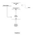
- FIG. 5shows a motion sensor, according to another embodiment.
- the external occupancy indicatoris provided by a sensing of lighting of a building fixture ( 540 ) associated with motion sensor. Specifically, if lighting proximate to the motion sensor 110 begins to dim and is fully illuminated shortly thereafter, then occupancy can be assumed, which can be used as an indicator that motion should be indicated by the motion sensor 110 .
- FIG. 6shows a motion sensor, according to another embodiment.
- the external occupancy indicatoris provided by a sensing of motion (motion sensor indicators) by of one or more external occupancy sensors 650 . That is, one or more other motion sensors located proximate to the motion sensor 110 are used to confirm or check the accuracy of the motion indicator of the motion sensor 110 .
- the external occupancy indicatoris generated based at least in part on the motion sensor indicators of one or more external occupancy sensors. That is, motion sensing or occupancy sensing of other sensors can be used to confirm whether the motion indicator of the motion sensor is correct or not, and therefore, whether the motion sensitivity of the motion sensor is too sensitive or not sensitive enough.
- the external occupancy indicatoris generated by receiving and processing a plurality of external occupancy sensor indicators from a plurality of external occupancy sensors. That is, the motion sensing of a plurality of external sensors is used to confirm whether the motion indicator of the motion sensor is correct or not, and therefore, whether the motion sensitivity of the motion sensor is too sensitive or not sensitive enough. In some embodiments, the more proximate the external sensors, the more accurate the external sensor indicator is in validating the motion indicator of the motion sensor.
- the external occupancy indicatoris generated by a weighting an influence of one or more of the plurality of external occupancy sensor indicators.
- the weightingis influenced by the proximity of one or more of the plurality of external occupancy sensors. That is, for example, the external sensor that is closest to the motion sensor may be given the greatest weighting.
- one or more external sensorsmay be determined to provide the most accurate indication of whether the motion sensor is actually subject to motion and/or occupancy, and these one or more external motion sensors may provide the greatest weighting. For example, sensors located near an entrance and/or exist to a space within a structure may prove to be the most accurate in occupancy detection, and therefore, be afforded the greatest weighting.
- the external occupancy indicatoris derived or influenced from sensing the location of an occupant of a structure in which the motion sensor is located.
- the sensing of the location of an occupantincludes receiving the location information from a mobile device associated with the occupant. This can be derived from a mobile device associated with the occupant. The location can be determined by the mobile device itself, and then provided to the motion sensor controller, which influences the motion sensitivity adjustment.
- a sensorsuch as, a Bluetooth sensor may sense the presence and location of the mobile device, and then provide this information to a controller the controls adjustment of the motion sensitivity.
- FIG. 7shows a building fixture and a motion sensor, according to an embodiment.
- a lighting control system 700includes the smart sensor system 702 that is interfaced with a high-voltage manager 704 , which is interfaced with a luminaire 740 .
- the sensor and associated lighting control of FIG. 7is one exemplary embodiment of the sensors that includes a motion sensor with an adjustable motion sensitivity.
- Many different sensor embodimentsare adapted for utilization of the described embodiments for sensing and/or tracking motion.
- sensors(such as, the previously described external sensors) that are not directly associated with light control are utilized.
- the motion sensing and/or tracking of the described embodimentscan be utilized for optimal control of lighting and other environmental controls of an area or structure that utilizes the motion tracking.
- the controlcan be configured to save energy and provide comfort to occupants of the area or structure.
- the high-voltage manager 704includes a controller (manager CPU) 720 that is coupled to the luminaire 740 , and to a smart sensor CPU 735 of the smart sensor system 702 . As shown, the smart sensor CPU 735 is coupled to a communication interface 750 , wherein the communication interface 750 couples the controller to an external device.
- the smart sensor system 702additionally includes a sensor 740 . As indicated, the sensor 740 can include one or more of a light sensor 741 , a motion sensor 742 (which includes the motion sensitivity adjustment), and temperature sensor 743 , and camera 744 and/or an air quality sensor 745 . It is to be understood that this is not an exhaustive list of sensors.
- the sensor 740is coupled to the smart sensor CPU 735 , and the sensor 740 generates a sensed input.
- at least one of the sensorsis utilized for communication with the user device.
- the smart sensor CPU 735provides the sensitivity adjustment of the motion sensor 110 .
- the smart sensor CPU 735at least aids the sensitivity adjustment of the motion sensor 110 .
- the external occupancy indicatoris provided by a sensing of energy consumption of a building fixture, such as, the light fixture 700 .
- the external occupancy indicatoris provided by a sensing of lighting of a building fixture, such as, the light fixture 700 .
- the external occupancy indicatorcan be at least partially provided by external sensors which are interfaced with the smart sensor CPU 735 through the communication interface 750 .
- the external occupancy indicatoris provided by a sensing a state of status of other available sensors, such as, sensors 741 , 743 , 744 , 745 of the sensor 740 .
- the state of status of the other available sensors 741 , 743 , 744 , 745can be used to confirm whether or not the motion indicator of the motion sensor 110 is correct, and therefore, whether or not the motion sensitivity of the motion sensor 110 should be adjusted.
- a Bluetooth sensor 746can additionally or alternatively be used to sense occupancy, and even the location of the occupant.
- the external occupancy indicatorcan be derived from sensing a location of an occupant of a structure in which the motion sensor is located. That is, the location of the occupant can be derived from a mobile device associated with the occupant. For an embodiment, the location of the occupant is received from the mobile device of the occupant.
- a sensorsuch as the Bluetooth sensor 746 can sense the mobile device and determine the location of the mobile device.
- the camera 744can be used to sense motion and/or occupancy, and images of the camera 744 can be used to influence the external occupancy indicator.
- the external occupancy detectionis influenced by a badging system or other system that monitors entrance and exit of occupants of the structure.
- sensorsmay be positioned to sense when doors of an entrance of exit are opened and closed.
- the temperature sensor 743is utilized for motion tracking.
- the temperature sensor 743is utilized to determine how much and/or how quickly the temperature in the room has increased since the start of, for example, a meeting of occupants. How much the temperate has increased and how quickly the temperature has increased can be correlated with the number of the occupants. All of this is dependent on the dimensions of the room and related to previous occupied periods.
- estimates and/or knowledge of the number of occupants within a roomare used to adjust the HVAC (heating, ventilation and air conditioning) of the room.
- the temperature of the roomis adjusted based on the estimated number of occupants in the room.
- the controllersare operative to control a light output of the luminaire 740 based at least in part on the sensed input, and communicate at least one of state or sensed information to the external device.
- the high-voltage manager 704receives the high-power voltage and generates power control for the luminaire 740 , and generates a low-voltage supply for the smart sensor system 702 .
- the high-voltage manager 704 and the smart sensor system 702interact to control a light output of the luminaire 740 based at least in part on the sensed input, and communicate at least one of state or sensed information to the external device.
- the high-voltage manager 704 and the smart sensor system 702can also receive state or control information from the external device, which can influence the control of the light output of the luminaire 740 .
- manager CPU 720 of the high-voltage manager 704 and the smart sensor CPU 735 of the smart sensor system 702are shown as separate controllers, it is to be understood that for at least some embodiments the two separate controllers (CPUs) 720 , 735 can be implemented as single controller or CPU.
- the communication interface 750provides a wireless link to external devices (for example, the central controller, the user device and/or other lighting sub-systems or devices, and external sensors).
- external devicesfor example, the central controller, the user device and/or other lighting sub-systems or devices, and external sensors.
- An embodiment of the high-voltage manager 704 of the lighting control sub-system 700further includes an energy meter (also referred to as a power monitoring unit), which receives the electrical power of the lighting control sub-system 700 .
- the energy metermeasures and monitors the power being dissipated by the lighting control sub-system 700 .
- the monitoring of the dissipated powerprovides for precise monitoring of the dissipated power. Therefore, if the manager CPU 720 receives a demand response (typically, a request from a power company that is received during periods of high power demands) from, for example, a power company, the manager CPU 720 can determine how well the lighting control sub-system 700 is responding to the received demand response. Additionally, or alternatively, the manager CPU 720 can provide indications of how much energy (power) is being used, or saved.
- a demand responsetypically, a request from a power company that is received during periods of high power demands
- the manager CPU 720can determine how well the lighting control sub-system 700 is responding to the received
- FIG. 8is a flow chart that includes steps of a method of motion sensing, according to another embodiment.
- a first step 810includes generating, by a motion sensor, an output that indicates whether or not motion has been sensed by the motion sensor, wherein the motion sensor receives a motion sensitivity input, wherein the motion sensitivity input controls a level of motion sensitivity of the motion sensor.
- a second step 820includes generating, by a controller, the motion sensitivity input based at least in part on the output of the motion sensor.
- the controllergenerates the motion sensitivity input based at least in part on the output of the motion sensor over time. As previously described, for an embodiment, the controller generates the motion sensitivity input based at least in part on the output of the motion sensor and an external occupancy indicator that indicates a sensed occupancy of an area associated with the motion sensing apparatus. As previously described, for an embodiment, the external occupancy indicator is generated based on sensing a behavior of a building fixture associated with the motion sensing apparatus.
- the external occupancy indicatoris generated based on motion sensor indicators of one or more external occupancy sensors. As previously described, for an embodiment, the external occupancy indicator is generated based at least in part on the on motion sensor indicators of one or more external occupancy sensors over time. As previously described, for an embodiment, the external occupancy indicator is generated by receiving and processing a plurality of external occupancy sensor indicators from a plurality of external occupancy sensors. As previously described, for an embodiment, the external occupancy indicator is generated by a weighting an influence of one or more of the plurality of external occupancy sensor indicators. As previously described, for an embodiment, the weighting is influenced by a proximity of one or more of the plurality of external occupancy sensors.
- FIG. 9shows a structure that includes multiple motion sensors for controlling an environmental parameter of the structure, according to an embodiment.
- a sensor 922is designated as a sensor of interest (SOI).
- the motion sensitivity of this motion sensor 922is adjusted based on an external occupancy indicator, wherein the external occupancy indicator is generated at least in part based on sensing of other sensors 923 , 924 , 925 , 934 , 935 , 936 , 937 , 946 , 947 , 948 , 949 , 992 , 993 , 994 , 995 , 996 , 997 , wherein at least some of the other sensors are motion sensors.
- a structureincludes a first area 920 and a second area 930 .
- a controller 990is shown which can be an external controller that performs the processing, or can be multiple controllers associated with the sensors which distribute the processing, or a combination of both.
- statistical analysisis performed by the processing of sensed outputs of one or more of the other sensors to generate the external occupancy indicator, which as previously described, is used to generate the motion sensitivity adjustment of the SOI 922 .
- the sensors closest to the SOI 922have the greatest influence on the motion sensitivity adjustment of the SOI 922 .
- the SOI 922may be located next to a doorway of the first area 920 and a sensor (such as, sensor 993 ) may be located next to the same doorway, but with the second area 990 .
- the sensor 993may not be the most proximate sensor, but may be a strong indicator of motion detection as an occupant passes through the doorway between the second area 990 and the first area 920 .
- the activation of lighting or the use of energy within the area 920 of the SOI 922can also be used for occupancy and/or motion detection which can be used to confirm motion sensing of the SOI 922 .
- the SOIis a sensor that includes the adjustable motion sensitivity.
- each sensor Siis given a weighting which represents the sensors relationship or correlation with the SOI. That is, how reliable the indicator from the sensor Si is in predicting the proper indicator of the SOI.
- an EOI(external occupancy indicator for the sensor of interest at time T) can be estimated or determined using the Si(T) (sensed state of sensor Si), the r(Si) (the weighting reliability of Si), and the d(SOI, Si) (distance between the SOI and Si).
- the RBFprovides weighting to neighboring sensors based on a distance between the neighboring sensor and the SOI.
Landscapes
- Engineering & Computer Science (AREA)
- Physics & Mathematics (AREA)
- General Physics & Mathematics (AREA)
- Automation & Control Theory (AREA)
- Health & Medical Sciences (AREA)
- Artificial Intelligence (AREA)
- Computer Vision & Pattern Recognition (AREA)
- Evolutionary Computation (AREA)
- Medical Informatics (AREA)
- Software Systems (AREA)
- Circuit Arrangement For Electric Light Sources In General (AREA)
Abstract
Description
d(S1,S2)=((x1−x2)2+(y1−y2)2)1/2, whereinS1 isafirst sensor (for example, the SOI) andS2 is a second sensor.
RBF(distance)=(1/distance) or (1/(distance)2), or . . .
W(Si)=r(Si)*RBF(d(Si)); and
EOI(Si)=(ΣSi(T)*W(Si))/(ΣW(Si)) whereini=0 ton;
Claims (21)
Priority Applications (1)
| Application Number | Priority Date | Filing Date | Title |
|---|---|---|---|
| US15/197,344US10372097B2 (en) | 2016-06-29 | 2016-06-29 | Adaptive adjustment of motion sensitivity of a motion sensor |
Applications Claiming Priority (1)
| Application Number | Priority Date | Filing Date | Title |
|---|---|---|---|
| US15/197,344US10372097B2 (en) | 2016-06-29 | 2016-06-29 | Adaptive adjustment of motion sensitivity of a motion sensor |
Publications (2)
| Publication Number | Publication Date |
|---|---|
| US20180004177A1 US20180004177A1 (en) | 2018-01-04 |
| US10372097B2true US10372097B2 (en) | 2019-08-06 |
Family
ID=60807382
Family Applications (1)
| Application Number | Title | Priority Date | Filing Date |
|---|---|---|---|
| US15/197,344Active2037-08-28US10372097B2 (en) | 2016-06-29 | 2016-06-29 | Adaptive adjustment of motion sensitivity of a motion sensor |
Country Status (1)
| Country | Link |
|---|---|
| US (1) | US10372097B2 (en) |
Cited By (1)
| Publication number | Priority date | Publication date | Assignee | Title |
|---|---|---|---|---|
| US20200221558A1 (en)* | 2017-08-22 | 2020-07-09 | Signify Holding B.V. | Device, system, and method for determining occupancy for automated lighting operations |
Families Citing this family (1)
| Publication number | Priority date | Publication date | Assignee | Title |
|---|---|---|---|---|
| CN114710863B (en)* | 2022-03-29 | 2023-09-05 | 惠州莫思特智照科技有限公司 | Intelligent induction control method and device |
Citations (53)
| Publication number | Priority date | Publication date | Assignee | Title |
|---|---|---|---|---|
| US5101141A (en) | 1987-12-08 | 1992-03-31 | Legrand Electric Limited | Lighting control |
| US5179324A (en) | 1991-01-21 | 1993-01-12 | Legrand | Dimmer with reduced filtering losses |
| US5191265A (en) | 1991-08-09 | 1993-03-02 | Lutron Electronics Co., Inc. | Wall mounted programmable modular control system |
| US5283516A (en) | 1993-02-24 | 1994-02-01 | Pass & Seymour Legrand | Low voltage dimmer with no load protection |
| US5376925A (en)* | 1992-10-21 | 1994-12-27 | Pulse Electronics, Inc. | Motion and direction sensors |
| US5812422A (en) | 1995-09-07 | 1998-09-22 | Philips Electronics North America Corporation | Computer software for optimizing energy efficiency of a lighting system for a target energy consumption level |
| US6057654A (en) | 1998-05-14 | 2000-05-02 | Legrand | Method and apparatus for automatically controlling a lighting load |
| US6084450A (en)* | 1997-01-14 | 2000-07-04 | The Regents Of The University Of California | PWM controller with one cycle response |
| US6188181B1 (en) | 1998-08-25 | 2001-02-13 | Lutron Electronics Co., Inc. | Lighting control system for different load types |
| US6342994B1 (en) | 1997-12-12 | 2002-01-29 | Legrand | Protective device against excessive currents, in particular for resettable protection of a controlled switch |
| US6548967B1 (en) | 1997-08-26 | 2003-04-15 | Color Kinetics, Inc. | Universal lighting network methods and systems |
| US20040002792A1 (en) | 2002-06-28 | 2004-01-01 | Encelium Technologies Inc. | Lighting energy management system and method |
| US20050169643A1 (en) | 1997-01-02 | 2005-08-04 | Franklin Philip G. | Method and apparatus for the zonal transmission of data using building lighting fixtures |
| US20050278047A1 (en) | 2004-03-25 | 2005-12-15 | Siemens Building Technologies, Inc | Method and apparatus for generating a building system model |
| US20060197481A1 (en)* | 2005-03-04 | 2006-09-07 | Linear Corporation | Motion control system for barrier drive |
| US20070057807A1 (en) | 2005-09-12 | 2007-03-15 | Acuity Brands, Inc. | Activation device for an intelligent luminaire manager |
| US20070086128A1 (en) | 2004-09-28 | 2007-04-19 | Acuity Brands, Inc. | Equipment and methods for emergency lighting that provides brownout detection and protection |
| US20070215794A1 (en) | 2006-03-15 | 2007-09-20 | Honeywell International, Inc. | Light sensor and light sensing method |
| US7309985B2 (en) | 2003-04-23 | 2007-12-18 | Koninklijke Philips Electronics N. V. | Method of reconstructing an MR image |
| US7348736B2 (en) | 2005-01-24 | 2008-03-25 | Philips Solid-State Lighting Solutions | Methods and apparatus for providing workspace lighting and facilitating workspace customization |
| US7382271B2 (en) | 2004-09-29 | 2008-06-03 | Siemens Building Technologies, Inc. | Automated position detection for wireless building automation devices |
| US20080185597A1 (en) | 2007-02-06 | 2008-08-07 | Universal Scientific Industrial Co., Ltd. | Light-emitting module |
| US20080244104A1 (en) | 2007-03-28 | 2008-10-02 | Johnson Controls Technology Company | Building automation system field devices and adapters |
| US7437596B2 (en) | 2004-10-05 | 2008-10-14 | Siemens Building Technologies, Inc. | Self-healing control network for building automation systems |
| US20080265796A1 (en) | 2002-09-25 | 2008-10-30 | Jonathan Null | Light management system device and method |
| US20090026966A1 (en) | 2006-03-07 | 2009-01-29 | Koninklijke Philips Electronics N V | Lighting system with lighting units using optical communication |
| US7550931B2 (en) | 2001-05-30 | 2009-06-23 | Philips Solid-State Lighting Solutions, Inc. | Controlled lighting methods and apparatus |
| US20090179596A1 (en) | 2006-05-11 | 2009-07-16 | Koninklijke Philips Electronics N V | Integrated lighting control module and power switch |
| US7566137B2 (en) | 2003-03-24 | 2009-07-28 | Lutron Electronics Co., Inc. | System to control daylight and electric light in a space |
| US7623042B2 (en) | 2005-03-14 | 2009-11-24 | Regents Of The University Of California | Wireless network control for building lighting system |
| US20100034386A1 (en) | 2008-08-06 | 2010-02-11 | Daintree Networks, Pty. Ltd. | Device manager repository |
| US20100135186A1 (en) | 2005-01-24 | 2010-06-03 | Daintree Networks, Pty. Ltd. | Network Analysis System and Method |
| US20100141153A1 (en)* | 2006-03-28 | 2010-06-10 | Recker Michael V | Wireless lighting devices and applications |
| US20100264846A1 (en) | 2008-04-14 | 2010-10-21 | Digital Lumens, Inc. | Power Management Unit with Adaptive Dimming |
| US20100270933A1 (en) | 2008-04-14 | 2010-10-28 | Digital Lumens, Inc. | Power Management Unit with Power Metering |
| US20100295482A1 (en) | 2009-04-14 | 2010-11-25 | Digital Lumens, Inc. | Power Management Unit with Multi-Input Arbitration |
| US20100301777A1 (en) | 2007-09-07 | 2010-12-02 | Regine Kraemer | Method and Device For Adjusting the Color or Photometric Properties of an Led Illumination Device |
| US20110031897A1 (en) | 2009-08-10 | 2011-02-10 | Redwood Systems, Inc. | Lighting systems and methods of auto-commissioning |
| US7925384B2 (en) | 2008-06-02 | 2011-04-12 | Adura Technologies, Inc. | Location-based provisioning of wireless control systems |
| US20110199010A1 (en) | 2010-02-17 | 2011-08-18 | Gye-Hyun Cho | Control device, led light emitting device including the same, and control method |
| US20120080944A1 (en)* | 2006-03-28 | 2012-04-05 | Wireless Environment, Llc. | Grid Shifting System for a Lighting Circuit |
| US8538596B2 (en) | 2010-12-20 | 2013-09-17 | Redwood Systems, Inc. | Light timeout optimization |
| US20130293113A1 (en) | 2012-05-07 | 2013-11-07 | Starfield Controls Inc. | Self Calibrating, Adaptive Setpoint Daylighting |
| US20140125234A1 (en)* | 2012-11-02 | 2014-05-08 | Laurence P. Sadwick | Dimmer with Motion and Light Sensing |
| US20140239817A1 (en)* | 2013-02-25 | 2014-08-28 | Leviton Manufacturing Company, Inc. | System and Method for Occupancy Sensing with Enhanced Functionality |
| US8909382B1 (en) | 2011-11-10 | 2014-12-09 | Universal Lighting Technologies, Inc. | Occupancy detection system and method having automatic adaptation capabilities |
| US20150116205A1 (en)* | 2012-05-09 | 2015-04-30 | Apple Inc. | Thresholds for determining feedback in computing devices |
| US20170120802A1 (en)* | 2015-11-04 | 2017-05-04 | GM Global Technology Operations LLC | User-following vehicle illumination system |
| US20170181252A1 (en)* | 2015-12-22 | 2017-06-22 | Rita H. Wouhaybi | Technologies for analyzing light exposure |
| US20170199504A1 (en)* | 2016-01-13 | 2017-07-13 | Fanuc Corporation | Motion controller |
| US20170238387A1 (en)* | 2016-02-11 | 2017-08-17 | Kenall Manufacturing Company | Hybrid Closed Loop Daylight Harvesting Control |
| US20170245347A1 (en)* | 2016-02-23 | 2017-08-24 | MW McWong International, Inc. | Sensor with wireless device for controlling a light source |
| US9906722B1 (en)* | 2016-04-07 | 2018-02-27 | Ambarella, Inc. | Power-saving battery-operated camera |
- 2016
- 2016-06-29USUS15/197,344patent/US10372097B2/enactiveActive
Patent Citations (57)
| Publication number | Priority date | Publication date | Assignee | Title |
|---|---|---|---|---|
| US5101141A (en) | 1987-12-08 | 1992-03-31 | Legrand Electric Limited | Lighting control |
| US5179324A (en) | 1991-01-21 | 1993-01-12 | Legrand | Dimmer with reduced filtering losses |
| US5191265A (en) | 1991-08-09 | 1993-03-02 | Lutron Electronics Co., Inc. | Wall mounted programmable modular control system |
| US5376925A (en)* | 1992-10-21 | 1994-12-27 | Pulse Electronics, Inc. | Motion and direction sensors |
| US5283516A (en) | 1993-02-24 | 1994-02-01 | Pass & Seymour Legrand | Low voltage dimmer with no load protection |
| US5812422A (en) | 1995-09-07 | 1998-09-22 | Philips Electronics North America Corporation | Computer software for optimizing energy efficiency of a lighting system for a target energy consumption level |
| US20050169643A1 (en) | 1997-01-02 | 2005-08-04 | Franklin Philip G. | Method and apparatus for the zonal transmission of data using building lighting fixtures |
| US20060275040A1 (en) | 1997-01-02 | 2006-12-07 | Franklin Philip G | Method and apparatus for the zonal transmission of data using building lighting fixtures |
| US6084450A (en)* | 1997-01-14 | 2000-07-04 | The Regents Of The University Of California | PWM controller with one cycle response |
| US6548967B1 (en) | 1997-08-26 | 2003-04-15 | Color Kinetics, Inc. | Universal lighting network methods and systems |
| US6342994B1 (en) | 1997-12-12 | 2002-01-29 | Legrand | Protective device against excessive currents, in particular for resettable protection of a controlled switch |
| US6057654A (en) | 1998-05-14 | 2000-05-02 | Legrand | Method and apparatus for automatically controlling a lighting load |
| US6188181B1 (en) | 1998-08-25 | 2001-02-13 | Lutron Electronics Co., Inc. | Lighting control system for different load types |
| US7550931B2 (en) | 2001-05-30 | 2009-06-23 | Philips Solid-State Lighting Solutions, Inc. | Controlled lighting methods and apparatus |
| US20040002792A1 (en) | 2002-06-28 | 2004-01-01 | Encelium Technologies Inc. | Lighting energy management system and method |
| US20070061050A1 (en) | 2002-06-28 | 2007-03-15 | Encelium Technologies Inc. | Lighting energy management system and method |
| US20080265796A1 (en) | 2002-09-25 | 2008-10-30 | Jonathan Null | Light management system device and method |
| US7566137B2 (en) | 2003-03-24 | 2009-07-28 | Lutron Electronics Co., Inc. | System to control daylight and electric light in a space |
| US7309985B2 (en) | 2003-04-23 | 2007-12-18 | Koninklijke Philips Electronics N. V. | Method of reconstructing an MR image |
| US20050278047A1 (en) | 2004-03-25 | 2005-12-15 | Siemens Building Technologies, Inc | Method and apparatus for generating a building system model |
| US20090195161A1 (en) | 2004-09-28 | 2009-08-06 | Acuity Brands, Inc. | Equipment and methods for emergency lighting that provides brownout detection and protection |
| US20070086128A1 (en) | 2004-09-28 | 2007-04-19 | Acuity Brands, Inc. | Equipment and methods for emergency lighting that provides brownout detection and protection |
| US7382271B2 (en) | 2004-09-29 | 2008-06-03 | Siemens Building Technologies, Inc. | Automated position detection for wireless building automation devices |
| US7437596B2 (en) | 2004-10-05 | 2008-10-14 | Siemens Building Technologies, Inc. | Self-healing control network for building automation systems |
| US7348736B2 (en) | 2005-01-24 | 2008-03-25 | Philips Solid-State Lighting Solutions | Methods and apparatus for providing workspace lighting and facilitating workspace customization |
| US20100135186A1 (en) | 2005-01-24 | 2010-06-03 | Daintree Networks, Pty. Ltd. | Network Analysis System and Method |
| US7792956B2 (en) | 2005-01-24 | 2010-09-07 | Daintree Networks, Pty. Ltd. | Network analysis system and method |
| US20060197481A1 (en)* | 2005-03-04 | 2006-09-07 | Linear Corporation | Motion control system for barrier drive |
| US7623042B2 (en) | 2005-03-14 | 2009-11-24 | Regents Of The University Of California | Wireless network control for building lighting system |
| US20070057807A1 (en) | 2005-09-12 | 2007-03-15 | Acuity Brands, Inc. | Activation device for an intelligent luminaire manager |
| US20090026966A1 (en) | 2006-03-07 | 2009-01-29 | Koninklijke Philips Electronics N V | Lighting system with lighting units using optical communication |
| US20070215794A1 (en) | 2006-03-15 | 2007-09-20 | Honeywell International, Inc. | Light sensor and light sensing method |
| US20120080944A1 (en)* | 2006-03-28 | 2012-04-05 | Wireless Environment, Llc. | Grid Shifting System for a Lighting Circuit |
| US20100141153A1 (en)* | 2006-03-28 | 2010-06-10 | Recker Michael V | Wireless lighting devices and applications |
| US20090179596A1 (en) | 2006-05-11 | 2009-07-16 | Koninklijke Philips Electronics N V | Integrated lighting control module and power switch |
| US20080185597A1 (en) | 2007-02-06 | 2008-08-07 | Universal Scientific Industrial Co., Ltd. | Light-emitting module |
| US20080244104A1 (en) | 2007-03-28 | 2008-10-02 | Johnson Controls Technology Company | Building automation system field devices and adapters |
| US20100301777A1 (en) | 2007-09-07 | 2010-12-02 | Regine Kraemer | Method and Device For Adjusting the Color or Photometric Properties of an Led Illumination Device |
| US20100270933A1 (en) | 2008-04-14 | 2010-10-28 | Digital Lumens, Inc. | Power Management Unit with Power Metering |
| US20100264846A1 (en) | 2008-04-14 | 2010-10-21 | Digital Lumens, Inc. | Power Management Unit with Adaptive Dimming |
| US7925384B2 (en) | 2008-06-02 | 2011-04-12 | Adura Technologies, Inc. | Location-based provisioning of wireless control systems |
| US20100034386A1 (en) | 2008-08-06 | 2010-02-11 | Daintree Networks, Pty. Ltd. | Device manager repository |
| US20100295482A1 (en) | 2009-04-14 | 2010-11-25 | Digital Lumens, Inc. | Power Management Unit with Multi-Input Arbitration |
| US20110031897A1 (en) | 2009-08-10 | 2011-02-10 | Redwood Systems, Inc. | Lighting systems and methods of auto-commissioning |
| US20110199010A1 (en) | 2010-02-17 | 2011-08-18 | Gye-Hyun Cho | Control device, led light emitting device including the same, and control method |
| US8538596B2 (en) | 2010-12-20 | 2013-09-17 | Redwood Systems, Inc. | Light timeout optimization |
| US8909382B1 (en) | 2011-11-10 | 2014-12-09 | Universal Lighting Technologies, Inc. | Occupancy detection system and method having automatic adaptation capabilities |
| US20130293113A1 (en) | 2012-05-07 | 2013-11-07 | Starfield Controls Inc. | Self Calibrating, Adaptive Setpoint Daylighting |
| US20150116205A1 (en)* | 2012-05-09 | 2015-04-30 | Apple Inc. | Thresholds for determining feedback in computing devices |
| US20140125234A1 (en)* | 2012-11-02 | 2014-05-08 | Laurence P. Sadwick | Dimmer with Motion and Light Sensing |
| US20140239817A1 (en)* | 2013-02-25 | 2014-08-28 | Leviton Manufacturing Company, Inc. | System and Method for Occupancy Sensing with Enhanced Functionality |
| US20170120802A1 (en)* | 2015-11-04 | 2017-05-04 | GM Global Technology Operations LLC | User-following vehicle illumination system |
| US20170181252A1 (en)* | 2015-12-22 | 2017-06-22 | Rita H. Wouhaybi | Technologies for analyzing light exposure |
| US20170199504A1 (en)* | 2016-01-13 | 2017-07-13 | Fanuc Corporation | Motion controller |
| US20170238387A1 (en)* | 2016-02-11 | 2017-08-17 | Kenall Manufacturing Company | Hybrid Closed Loop Daylight Harvesting Control |
| US20170245347A1 (en)* | 2016-02-23 | 2017-08-24 | MW McWong International, Inc. | Sensor with wireless device for controlling a light source |
| US9906722B1 (en)* | 2016-04-07 | 2018-02-27 | Ambarella, Inc. | Power-saving battery-operated camera |
Cited By (2)
| Publication number | Priority date | Publication date | Assignee | Title |
|---|---|---|---|---|
| US20200221558A1 (en)* | 2017-08-22 | 2020-07-09 | Signify Holding B.V. | Device, system, and method for determining occupancy for automated lighting operations |
| US11026315B2 (en)* | 2017-08-22 | 2021-06-01 | Signify Holding B.V. | Device, system, and method for determining occupancy for automated lighting operations |
Also Published As
| Publication number | Publication date |
|---|---|
| US20180004177A1 (en) | 2018-01-04 |
Similar Documents
| Publication | Publication Date | Title |
|---|---|---|
| EP3194858B1 (en) | Temperature control method and apparatus | |
| US9261289B2 (en) | Adjusting proximity thresholds for activating a device user interface | |
| CN104144537B (en) | Intelligent lighting controls method, equipment and system | |
| US10788803B2 (en) | System and method for maintaining building automation system performance | |
| EP3078919A1 (en) | Apparatus and method for controlling comfort temperature of air conditioning device or air conditioning system | |
| US9668320B2 (en) | Path light feedback compensation | |
| EP2982223B1 (en) | Anti-tampering daylight harvesting system | |
| KR101214235B1 (en) | Wireless sensing module, wireless lighting controller and wireless lighting system | |
| US20150177716A1 (en) | Occupancy detection | |
| EP3633643B1 (en) | Drowsiness estimating device, awakening-induction control device, and awakening induction system | |
| US10372097B2 (en) | Adaptive adjustment of motion sensitivity of a motion sensor | |
| CN105165126A (en) | Lighting control system and lighting control method | |
| EP3681251B1 (en) | Predictive lighting control | |
| JPH11132530A (en) | Room-specific air conditioning control device | |
| JP5113568B2 (en) | Environmental control system | |
| JP6532824B2 (en) | Lighting control analyzer | |
| CN108917134B (en) | A kind of body-sensing air quantity adjusting method, device and air conditioner | |
| KR20220135943A (en) | Method for controlling environment of target area by detecting occupancy of target area | |
| US10783767B2 (en) | Device and method for controlling bluetooth enabled occupancy sensors | |
| JP2015017767A (en) | Air-conditioning system and air-conditioning method | |
| KR102200634B1 (en) | Method and Apparatus for Operating Building Equipment based on Occupants in Building | |
| WO2014097072A1 (en) | System and method for occupancy detection | |
| CN110701752B (en) | Operation control method and device, air conditioner and storage medium | |
| JP7511172B2 (en) | Equipment control system and determination method | |
| EP4188039B1 (en) | A management system and a method for controlling luminaires |
Legal Events
| Date | Code | Title | Description |
|---|---|---|---|
| AS | Assignment | Owner name:ENLIGHTED, INC., CALIFORNIA Free format text:ASSIGNMENT OF ASSIGNORS INTEREST;ASSIGNOR:HYMAN, NICK;REEL/FRAME:039046/0294 Effective date:20160628 | |
| AS | Assignment | Owner name:PACIFIC WESTERN BANK, NORTH CAROLINA Free format text:SECURITY INTEREST;ASSIGNOR:ENLIGHTED, INC.;REEL/FRAME:045386/0576 Effective date:20180216 | |
| FEPP | Fee payment procedure | Free format text:ENTITY STATUS SET TO UNDISCOUNTED (ORIGINAL EVENT CODE: BIG.); ENTITY STATUS OF PATENT OWNER: LARGE ENTITY | |
| STPP | Information on status: patent application and granting procedure in general | Free format text:NOTICE OF ALLOWANCE MAILED -- APPLICATION RECEIVED IN OFFICE OF PUBLICATIONS | |
| STPP | Information on status: patent application and granting procedure in general | Free format text:PUBLICATIONS -- ISSUE FEE PAYMENT RECEIVED | |
| STCF | Information on status: patent grant | Free format text:PATENTED CASE | |
| AS | Assignment | Owner name:BUILDING ROBOTICS, INC., CALIFORNIA Free format text:MERGER;ASSIGNOR:ENLIGHTED, INC.;REEL/FRAME:057883/0238 Effective date:20210929 | |
| MAFP | Maintenance fee payment | Free format text:PAYMENT OF MAINTENANCE FEE, 4TH YEAR, LARGE ENTITY (ORIGINAL EVENT CODE: M1551); ENTITY STATUS OF PATENT OWNER: LARGE ENTITY Year of fee payment:4 |