US10370102B2 - Systems, apparatuses and methods for unmanned aerial vehicle - Google Patents
Systems, apparatuses and methods for unmanned aerial vehicleDownload PDFInfo
- Publication number
- US10370102B2 US10370102B2US15/664,187US201715664187AUS10370102B2US 10370102 B2US10370102 B2US 10370102B2US 201715664187 AUS201715664187 AUS 201715664187AUS 10370102 B2US10370102 B2US 10370102B2
- Authority
- US
- United States
- Prior art keywords
- uav
- data
- docking station
- vehicle
- audio
- Prior art date
- Legal status (The legal status is an assumption and is not a legal conclusion. Google has not performed a legal analysis and makes no representation as to the accuracy of the status listed.)
- Active
Links
Images


Classifications
- B—PERFORMING OPERATIONS; TRANSPORTING
- B60—VEHICLES IN GENERAL
- B60L—PROPULSION OF ELECTRICALLY-PROPELLED VEHICLES; SUPPLYING ELECTRIC POWER FOR AUXILIARY EQUIPMENT OF ELECTRICALLY-PROPELLED VEHICLES; ELECTRODYNAMIC BRAKE SYSTEMS FOR VEHICLES IN GENERAL; MAGNETIC SUSPENSION OR LEVITATION FOR VEHICLES; MONITORING OPERATING VARIABLES OF ELECTRICALLY-PROPELLED VEHICLES; ELECTRIC SAFETY DEVICES FOR ELECTRICALLY-PROPELLED VEHICLES
- B60L53/00—Methods of charging batteries, specially adapted for electric vehicles; Charging stations or on-board charging equipment therefor; Exchange of energy storage elements in electric vehicles
- B60L53/60—Monitoring or controlling charging stations
- B60L53/66—Data transfer between charging stations and vehicles
- B—PERFORMING OPERATIONS; TRANSPORTING
- B64—AIRCRAFT; AVIATION; COSMONAUTICS
- B64C—AEROPLANES; HELICOPTERS
- B64C39/00—Aircraft not otherwise provided for
- B64C39/02—Aircraft not otherwise provided for characterised by special use
- B64C39/024—Aircraft not otherwise provided for characterised by special use of the remote controlled vehicle type, i.e. RPV
- B—PERFORMING OPERATIONS; TRANSPORTING
- B60—VEHICLES IN GENERAL
- B60L—PROPULSION OF ELECTRICALLY-PROPELLED VEHICLES; SUPPLYING ELECTRIC POWER FOR AUXILIARY EQUIPMENT OF ELECTRICALLY-PROPELLED VEHICLES; ELECTRODYNAMIC BRAKE SYSTEMS FOR VEHICLES IN GENERAL; MAGNETIC SUSPENSION OR LEVITATION FOR VEHICLES; MONITORING OPERATING VARIABLES OF ELECTRICALLY-PROPELLED VEHICLES; ELECTRIC SAFETY DEVICES FOR ELECTRICALLY-PROPELLED VEHICLES
- B60L53/00—Methods of charging batteries, specially adapted for electric vehicles; Charging stations or on-board charging equipment therefor; Exchange of energy storage elements in electric vehicles
- B60L53/10—Methods of charging batteries, specially adapted for electric vehicles; Charging stations or on-board charging equipment therefor; Exchange of energy storage elements in electric vehicles characterised by the energy transfer between the charging station and the vehicle
- B60L53/14—Conductive energy transfer
- B60L53/18—Cables specially adapted for charging electric vehicles
- B—PERFORMING OPERATIONS; TRANSPORTING
- B60—VEHICLES IN GENERAL
- B60L—PROPULSION OF ELECTRICALLY-PROPELLED VEHICLES; SUPPLYING ELECTRIC POWER FOR AUXILIARY EQUIPMENT OF ELECTRICALLY-PROPELLED VEHICLES; ELECTRODYNAMIC BRAKE SYSTEMS FOR VEHICLES IN GENERAL; MAGNETIC SUSPENSION OR LEVITATION FOR VEHICLES; MONITORING OPERATING VARIABLES OF ELECTRICALLY-PROPELLED VEHICLES; ELECTRIC SAFETY DEVICES FOR ELECTRICALLY-PROPELLED VEHICLES
- B60L53/00—Methods of charging batteries, specially adapted for electric vehicles; Charging stations or on-board charging equipment therefor; Exchange of energy storage elements in electric vehicles
- B60L53/60—Monitoring or controlling charging stations
- B—PERFORMING OPERATIONS; TRANSPORTING
- B64—AIRCRAFT; AVIATION; COSMONAUTICS
- B64D—EQUIPMENT FOR FITTING IN OR TO AIRCRAFT; FLIGHT SUITS; PARACHUTES; ARRANGEMENT OR MOUNTING OF POWER PLANTS OR PROPULSION TRANSMISSIONS IN AIRCRAFT
- B64D47/00—Equipment not otherwise provided for
- B64D47/08—Arrangements of cameras
- G—PHYSICS
- G06—COMPUTING OR CALCULATING; COUNTING
- G06F—ELECTRIC DIGITAL DATA PROCESSING
- G06F3/00—Input arrangements for transferring data to be processed into a form capable of being handled by the computer; Output arrangements for transferring data from processing unit to output unit, e.g. interface arrangements
- G06F3/16—Sound input; Sound output
- G06F3/165—Management of the audio stream, e.g. setting of volume, audio stream path
- G06K9/00771—
- G—PHYSICS
- G06—COMPUTING OR CALCULATING; COUNTING
- G06T—IMAGE DATA PROCESSING OR GENERATION, IN GENERAL
- G06T7/00—Image analysis
- G06T7/70—Determining position or orientation of objects or cameras
- G—PHYSICS
- G06—COMPUTING OR CALCULATING; COUNTING
- G06V—IMAGE OR VIDEO RECOGNITION OR UNDERSTANDING
- G06V20/00—Scenes; Scene-specific elements
- G06V20/50—Context or environment of the image
- G06V20/52—Surveillance or monitoring of activities, e.g. for recognising suspicious objects
- G—PHYSICS
- G08—SIGNALLING
- G08B—SIGNALLING OR CALLING SYSTEMS; ORDER TELEGRAPHS; ALARM SYSTEMS
- G08B13/00—Burglar, theft or intruder alarms
- G08B13/18—Actuation by interference with heat, light, or radiation of shorter wavelength; Actuation by intruding sources of heat, light, or radiation of shorter wavelength
- G08B13/189—Actuation by interference with heat, light, or radiation of shorter wavelength; Actuation by intruding sources of heat, light, or radiation of shorter wavelength using passive radiation detection systems
- G08B13/194—Actuation by interference with heat, light, or radiation of shorter wavelength; Actuation by intruding sources of heat, light, or radiation of shorter wavelength using passive radiation detection systems using image scanning and comparing systems
- G08B13/196—Actuation by interference with heat, light, or radiation of shorter wavelength; Actuation by intruding sources of heat, light, or radiation of shorter wavelength using passive radiation detection systems using image scanning and comparing systems using television cameras
- G08B13/19617—Surveillance camera constructional details
- G08B13/19621—Portable camera
- G—PHYSICS
- G08—SIGNALLING
- G08B—SIGNALLING OR CALLING SYSTEMS; ORDER TELEGRAPHS; ALARM SYSTEMS
- G08B13/00—Burglar, theft or intruder alarms
- G08B13/18—Actuation by interference with heat, light, or radiation of shorter wavelength; Actuation by intruding sources of heat, light, or radiation of shorter wavelength
- G08B13/189—Actuation by interference with heat, light, or radiation of shorter wavelength; Actuation by intruding sources of heat, light, or radiation of shorter wavelength using passive radiation detection systems
- G08B13/194—Actuation by interference with heat, light, or radiation of shorter wavelength; Actuation by intruding sources of heat, light, or radiation of shorter wavelength using passive radiation detection systems using image scanning and comparing systems
- G08B13/196—Actuation by interference with heat, light, or radiation of shorter wavelength; Actuation by intruding sources of heat, light, or radiation of shorter wavelength using passive radiation detection systems using image scanning and comparing systems using television cameras
- G08B13/19654—Details concerning communication with a camera
- G08B13/1966—Wireless systems, other than telephone systems, used to communicate with a camera
- G—PHYSICS
- G08—SIGNALLING
- G08B—SIGNALLING OR CALLING SYSTEMS; ORDER TELEGRAPHS; ALARM SYSTEMS
- G08B13/00—Burglar, theft or intruder alarms
- G08B13/18—Actuation by interference with heat, light, or radiation of shorter wavelength; Actuation by intruding sources of heat, light, or radiation of shorter wavelength
- G08B13/189—Actuation by interference with heat, light, or radiation of shorter wavelength; Actuation by intruding sources of heat, light, or radiation of shorter wavelength using passive radiation detection systems
- G08B13/194—Actuation by interference with heat, light, or radiation of shorter wavelength; Actuation by intruding sources of heat, light, or radiation of shorter wavelength using passive radiation detection systems using image scanning and comparing systems
- G08B13/196—Actuation by interference with heat, light, or radiation of shorter wavelength; Actuation by intruding sources of heat, light, or radiation of shorter wavelength using passive radiation detection systems using image scanning and comparing systems using television cameras
- G08B13/19665—Details related to the storage of video surveillance data
- G08B13/19669—Event triggers storage or change of storage policy
- G—PHYSICS
- G10—MUSICAL INSTRUMENTS; ACOUSTICS
- G10L—SPEECH ANALYSIS TECHNIQUES OR SPEECH SYNTHESIS; SPEECH RECOGNITION; SPEECH OR VOICE PROCESSING TECHNIQUES; SPEECH OR AUDIO CODING OR DECODING
- G10L25/00—Speech or voice analysis techniques not restricted to a single one of groups G10L15/00 - G10L21/00
- G10L25/48—Speech or voice analysis techniques not restricted to a single one of groups G10L15/00 - G10L21/00 specially adapted for particular use
- G10L25/51—Speech or voice analysis techniques not restricted to a single one of groups G10L15/00 - G10L21/00 specially adapted for particular use for comparison or discrimination
- G—PHYSICS
- G11—INFORMATION STORAGE
- G11B—INFORMATION STORAGE BASED ON RELATIVE MOVEMENT BETWEEN RECORD CARRIER AND TRANSDUCER
- G11B27/00—Editing; Indexing; Addressing; Timing or synchronising; Monitoring; Measuring tape travel
- G11B27/10—Indexing; Addressing; Timing or synchronising; Measuring tape travel
- G11B27/19—Indexing; Addressing; Timing or synchronising; Measuring tape travel by using information detectable on the record carrier
- G11B27/28—Indexing; Addressing; Timing or synchronising; Measuring tape travel by using information detectable on the record carrier by using information signals recorded by the same method as the main recording
- H—ELECTRICITY
- H04—ELECTRIC COMMUNICATION TECHNIQUE
- H04B—TRANSMISSION
- H04B7/00—Radio transmission systems, i.e. using radiation field
- H04B7/14—Relay systems
- H04B7/15—Active relay systems
- H04B7/185—Space-based or airborne stations; Stations for satellite systems
- H04B7/18502—Airborne stations
- H04B7/18506—Communications with or from aircraft, i.e. aeronautical mobile service
- H—ELECTRICITY
- H04—ELECTRIC COMMUNICATION TECHNIQUE
- H04N—PICTORIAL COMMUNICATION, e.g. TELEVISION
- H04N21/00—Selective content distribution, e.g. interactive television or video on demand [VOD]
- H04N21/20—Servers specifically adapted for the distribution of content, e.g. VOD servers; Operations thereof
- H04N21/23—Processing of content or additional data; Elementary server operations; Server middleware
- H04N21/236—Assembling of a multiplex stream, e.g. transport stream, by combining a video stream with other content or additional data, e.g. inserting a URL [Uniform Resource Locator] into a video stream, multiplexing software data into a video stream; Remultiplexing of multiplex streams; Insertion of stuffing bits into the multiplex stream, e.g. to obtain a constant bit-rate; Assembling of a packetised elementary stream
- H04N21/2368—Multiplexing of audio and video streams
- H—ELECTRICITY
- H04—ELECTRIC COMMUNICATION TECHNIQUE
- H04N—PICTORIAL COMMUNICATION, e.g. TELEVISION
- H04N21/00—Selective content distribution, e.g. interactive television or video on demand [VOD]
- H04N21/20—Servers specifically adapted for the distribution of content, e.g. VOD servers; Operations thereof
- H04N21/27—Server based end-user applications
- H04N21/274—Storing end-user multimedia data in response to end-user request, e.g. network recorder
- H04N21/2743—Video hosting of uploaded data from client
- H—ELECTRICITY
- H04—ELECTRIC COMMUNICATION TECHNIQUE
- H04N—PICTORIAL COMMUNICATION, e.g. TELEVISION
- H04N21/00—Selective content distribution, e.g. interactive television or video on demand [VOD]
- H04N21/40—Client devices specifically adapted for the reception of or interaction with content, e.g. set-top-box [STB]; Operations thereof
- H04N21/41—Structure of client; Structure of client peripherals
- H04N21/414—Specialised client platforms, e.g. receiver in car or embedded in a mobile appliance
- H04N21/41422—Specialised client platforms, e.g. receiver in car or embedded in a mobile appliance located in transportation means, e.g. personal vehicle
- H—ELECTRICITY
- H04—ELECTRIC COMMUNICATION TECHNIQUE
- H04N—PICTORIAL COMMUNICATION, e.g. TELEVISION
- H04N21/00—Selective content distribution, e.g. interactive television or video on demand [VOD]
- H04N21/40—Client devices specifically adapted for the reception of or interaction with content, e.g. set-top-box [STB]; Operations thereof
- H04N21/41—Structure of client; Structure of client peripherals
- H04N21/422—Input-only peripherals, i.e. input devices connected to specially adapted client devices, e.g. global positioning system [GPS]
- H04N21/4223—Cameras
- H—ELECTRICITY
- H04—ELECTRIC COMMUNICATION TECHNIQUE
- H04N—PICTORIAL COMMUNICATION, e.g. TELEVISION
- H04N21/00—Selective content distribution, e.g. interactive television or video on demand [VOD]
- H04N21/40—Client devices specifically adapted for the reception of or interaction with content, e.g. set-top-box [STB]; Operations thereof
- H04N21/43—Processing of content or additional data, e.g. demultiplexing additional data from a digital video stream; Elementary client operations, e.g. monitoring of home network or synchronising decoder's clock; Client middleware
- H04N21/4302—Content synchronisation processes, e.g. decoder synchronisation
- H—ELECTRICITY
- H04—ELECTRIC COMMUNICATION TECHNIQUE
- H04N—PICTORIAL COMMUNICATION, e.g. TELEVISION
- H04N21/00—Selective content distribution, e.g. interactive television or video on demand [VOD]
- H04N21/40—Client devices specifically adapted for the reception of or interaction with content, e.g. set-top-box [STB]; Operations thereof
- H04N21/43—Processing of content or additional data, e.g. demultiplexing additional data from a digital video stream; Elementary client operations, e.g. monitoring of home network or synchronising decoder's clock; Client middleware
- H04N21/435—Processing of additional data, e.g. decrypting of additional data, reconstructing software from modules extracted from the transport stream
- H—ELECTRICITY
- H04—ELECTRIC COMMUNICATION TECHNIQUE
- H04N—PICTORIAL COMMUNICATION, e.g. TELEVISION
- H04N21/00—Selective content distribution, e.g. interactive television or video on demand [VOD]
- H04N21/40—Client devices specifically adapted for the reception of or interaction with content, e.g. set-top-box [STB]; Operations thereof
- H04N21/43—Processing of content or additional data, e.g. demultiplexing additional data from a digital video stream; Elementary client operations, e.g. monitoring of home network or synchronising decoder's clock; Client middleware
- H04N21/439—Processing of audio elementary streams
- H04N21/4394—Processing of audio elementary streams involving operations for analysing the audio stream, e.g. detecting features or characteristics in audio streams
- H—ELECTRICITY
- H04—ELECTRIC COMMUNICATION TECHNIQUE
- H04N—PICTORIAL COMMUNICATION, e.g. TELEVISION
- H04N21/00—Selective content distribution, e.g. interactive television or video on demand [VOD]
- H04N21/80—Generation or processing of content or additional data by content creator independently of the distribution process; Content per se
- H04N21/81—Monomedia components thereof
- H04N21/8106—Monomedia components thereof involving special audio data, e.g. different tracks for different languages
- H—ELECTRICITY
- H04—ELECTRIC COMMUNICATION TECHNIQUE
- H04N—PICTORIAL COMMUNICATION, e.g. TELEVISION
- H04N21/00—Selective content distribution, e.g. interactive television or video on demand [VOD]
- H04N21/80—Generation or processing of content or additional data by content creator independently of the distribution process; Content per se
- H04N21/83—Generation or processing of protective or descriptive data associated with content; Content structuring
- H04N21/84—Generation or processing of descriptive data, e.g. content descriptors
- H—ELECTRICITY
- H04—ELECTRIC COMMUNICATION TECHNIQUE
- H04N—PICTORIAL COMMUNICATION, e.g. TELEVISION
- H04N23/00—Cameras or camera modules comprising electronic image sensors; Control thereof
- H04N23/60—Control of cameras or camera modules
- H04N23/66—Remote control of cameras or camera parts, e.g. by remote control devices
- H04N23/661—Transmitting camera control signals through networks, e.g. control via the Internet
- H—ELECTRICITY
- H04—ELECTRIC COMMUNICATION TECHNIQUE
- H04N—PICTORIAL COMMUNICATION, e.g. TELEVISION
- H04N23/00—Cameras or camera modules comprising electronic image sensors; Control thereof
- H04N23/60—Control of cameras or camera modules
- H04N23/698—Control of cameras or camera modules for achieving an enlarged field of view, e.g. panoramic image capture
- H04N5/23206—
- H04N5/23238—
- H—ELECTRICITY
- H04—ELECTRIC COMMUNICATION TECHNIQUE
- H04N—PICTORIAL COMMUNICATION, e.g. TELEVISION
- H04N5/00—Details of television systems
- H04N5/76—Television signal recording
- H04N5/91—Television signal processing therefor
- H—ELECTRICITY
- H04—ELECTRIC COMMUNICATION TECHNIQUE
- H04R—LOUDSPEAKERS, MICROPHONES, GRAMOPHONE PICK-UPS OR LIKE ACOUSTIC ELECTROMECHANICAL TRANSDUCERS; DEAF-AID SETS; PUBLIC ADDRESS SYSTEMS
- H04R1/00—Details of transducers, loudspeakers or microphones
- H04R1/20—Arrangements for obtaining desired frequency or directional characteristics
- H04R1/32—Arrangements for obtaining desired frequency or directional characteristics for obtaining desired directional characteristic only
- H04R1/40—Arrangements for obtaining desired frequency or directional characteristics for obtaining desired directional characteristic only by combining a number of identical transducers
- H04R1/406—Arrangements for obtaining desired frequency or directional characteristics for obtaining desired directional characteristic only by combining a number of identical transducers microphones
- H—ELECTRICITY
- H04—ELECTRIC COMMUNICATION TECHNIQUE
- H04R—LOUDSPEAKERS, MICROPHONES, GRAMOPHONE PICK-UPS OR LIKE ACOUSTIC ELECTROMECHANICAL TRANSDUCERS; DEAF-AID SETS; PUBLIC ADDRESS SYSTEMS
- H04R29/00—Monitoring arrangements; Testing arrangements
- H—ELECTRICITY
- H04—ELECTRIC COMMUNICATION TECHNIQUE
- H04R—LOUDSPEAKERS, MICROPHONES, GRAMOPHONE PICK-UPS OR LIKE ACOUSTIC ELECTROMECHANICAL TRANSDUCERS; DEAF-AID SETS; PUBLIC ADDRESS SYSTEMS
- H04R3/00—Circuits for transducers, loudspeakers or microphones
- H04R3/005—Circuits for transducers, loudspeakers or microphones for combining the signals of two or more microphones
- B64C2201/127—
- B64C2201/141—
- B64C2201/146—
- B64C2201/208—
- B—PERFORMING OPERATIONS; TRANSPORTING
- B64—AIRCRAFT; AVIATION; COSMONAUTICS
- B64U—UNMANNED AERIAL VEHICLES [UAV]; EQUIPMENT THEREFOR
- B64U10/00—Type of UAV
- B64U10/10—Rotorcrafts
- B64U10/13—Flying platforms
- B—PERFORMING OPERATIONS; TRANSPORTING
- B64—AIRCRAFT; AVIATION; COSMONAUTICS
- B64U—UNMANNED AERIAL VEHICLES [UAV]; EQUIPMENT THEREFOR
- B64U2101/00—UAVs specially adapted for particular uses or applications
- B64U2101/30—UAVs specially adapted for particular uses or applications for imaging, photography or videography
- B—PERFORMING OPERATIONS; TRANSPORTING
- B64—AIRCRAFT; AVIATION; COSMONAUTICS
- B64U—UNMANNED AERIAL VEHICLES [UAV]; EQUIPMENT THEREFOR
- B64U2201/00—UAVs characterised by their flight controls
- B64U2201/10—UAVs characterised by their flight controls autonomous, i.e. by navigating independently from ground or air stations, e.g. by using inertial navigation systems [INS]
- B—PERFORMING OPERATIONS; TRANSPORTING
- B64—AIRCRAFT; AVIATION; COSMONAUTICS
- B64U—UNMANNED AERIAL VEHICLES [UAV]; EQUIPMENT THEREFOR
- B64U2201/00—UAVs characterised by their flight controls
- B64U2201/20—Remote controls
- B—PERFORMING OPERATIONS; TRANSPORTING
- B64—AIRCRAFT; AVIATION; COSMONAUTICS
- B64U—UNMANNED AERIAL VEHICLES [UAV]; EQUIPMENT THEREFOR
- B64U30/00—Means for producing lift; Empennages; Arrangements thereof
- B64U30/20—Rotors; Rotor supports
- B—PERFORMING OPERATIONS; TRANSPORTING
- B64—AIRCRAFT; AVIATION; COSMONAUTICS
- B64U—UNMANNED AERIAL VEHICLES [UAV]; EQUIPMENT THEREFOR
- B64U50/00—Propulsion; Power supply
- B64U50/30—Supply or distribution of electrical power
- B64U50/37—Charging when not in flight
- B—PERFORMING OPERATIONS; TRANSPORTING
- B64—AIRCRAFT; AVIATION; COSMONAUTICS
- B64U—UNMANNED AERIAL VEHICLES [UAV]; EQUIPMENT THEREFOR
- B64U70/00—Launching, take-off or landing arrangements
- B64U70/90—Launching from or landing on platforms
- B64U70/92—Portable platforms
- B64U70/93—Portable platforms for use on a land or nautical vehicle
- B—PERFORMING OPERATIONS; TRANSPORTING
- B64—AIRCRAFT; AVIATION; COSMONAUTICS
- B64U—UNMANNED AERIAL VEHICLES [UAV]; EQUIPMENT THEREFOR
- B64U80/00—Transport or storage specially adapted for UAVs
- B64U80/80—Transport or storage specially adapted for UAVs by vehicles
- B—PERFORMING OPERATIONS; TRANSPORTING
- B64—AIRCRAFT; AVIATION; COSMONAUTICS
- B64U—UNMANNED AERIAL VEHICLES [UAV]; EQUIPMENT THEREFOR
- B64U80/00—Transport or storage specially adapted for UAVs
- B64U80/80—Transport or storage specially adapted for UAVs by vehicles
- B64U80/86—Land vehicles
- G06K2009/00738—
- G—PHYSICS
- G06—COMPUTING OR CALCULATING; COUNTING
- G06V—IMAGE OR VIDEO RECOGNITION OR UNDERSTANDING
- G06V20/00—Scenes; Scene-specific elements
- G06V20/40—Scenes; Scene-specific elements in video content
- G06V20/44—Event detection
- H—ELECTRICITY
- H04—ELECTRIC COMMUNICATION TECHNIQUE
- H04R—LOUDSPEAKERS, MICROPHONES, GRAMOPHONE PICK-UPS OR LIKE ACOUSTIC ELECTROMECHANICAL TRANSDUCERS; DEAF-AID SETS; PUBLIC ADDRESS SYSTEMS
- H04R1/00—Details of transducers, loudspeakers or microphones
- H04R1/02—Casings; Cabinets ; Supports therefor; Mountings therein
- H04R1/028—Casings; Cabinets ; Supports therefor; Mountings therein associated with devices performing functions other than acoustics, e.g. electric candles
- H—ELECTRICITY
- H04—ELECTRIC COMMUNICATION TECHNIQUE
- H04R—LOUDSPEAKERS, MICROPHONES, GRAMOPHONE PICK-UPS OR LIKE ACOUSTIC ELECTROMECHANICAL TRANSDUCERS; DEAF-AID SETS; PUBLIC ADDRESS SYSTEMS
- H04R2420/00—Details of connection covered by H04R, not provided for in its groups
- H04R2420/07—Applications of wireless loudspeakers or wireless microphones
- H—ELECTRICITY
- H04—ELECTRIC COMMUNICATION TECHNIQUE
- H04R—LOUDSPEAKERS, MICROPHONES, GRAMOPHONE PICK-UPS OR LIKE ACOUSTIC ELECTROMECHANICAL TRANSDUCERS; DEAF-AID SETS; PUBLIC ADDRESS SYSTEMS
- H04R2430/00—Signal processing covered by H04R, not provided for in its groups
- H04R2430/20—Processing of the output signals of the acoustic transducers of an array for obtaining a desired directivity characteristic
- H04R2430/23—Direction finding using a sum-delay beam-former
- Y—GENERAL TAGGING OF NEW TECHNOLOGICAL DEVELOPMENTS; GENERAL TAGGING OF CROSS-SECTIONAL TECHNOLOGIES SPANNING OVER SEVERAL SECTIONS OF THE IPC; TECHNICAL SUBJECTS COVERED BY FORMER USPC CROSS-REFERENCE ART COLLECTIONS [XRACs] AND DIGESTS
- Y02—TECHNOLOGIES OR APPLICATIONS FOR MITIGATION OR ADAPTATION AGAINST CLIMATE CHANGE
- Y02T—CLIMATE CHANGE MITIGATION TECHNOLOGIES RELATED TO TRANSPORTATION
- Y02T10/00—Road transport of goods or passengers
- Y02T10/60—Other road transportation technologies with climate change mitigation effect
- Y02T10/70—Energy storage systems for electromobility, e.g. batteries
- Y—GENERAL TAGGING OF NEW TECHNOLOGICAL DEVELOPMENTS; GENERAL TAGGING OF CROSS-SECTIONAL TECHNOLOGIES SPANNING OVER SEVERAL SECTIONS OF THE IPC; TECHNICAL SUBJECTS COVERED BY FORMER USPC CROSS-REFERENCE ART COLLECTIONS [XRACs] AND DIGESTS
- Y02—TECHNOLOGIES OR APPLICATIONS FOR MITIGATION OR ADAPTATION AGAINST CLIMATE CHANGE
- Y02T—CLIMATE CHANGE MITIGATION TECHNOLOGIES RELATED TO TRANSPORTATION
- Y02T10/00—Road transport of goods or passengers
- Y02T10/60—Other road transportation technologies with climate change mitigation effect
- Y02T10/7072—Electromobility specific charging systems or methods for batteries, ultracapacitors, supercapacitors or double-layer capacitors
- Y—GENERAL TAGGING OF NEW TECHNOLOGICAL DEVELOPMENTS; GENERAL TAGGING OF CROSS-SECTIONAL TECHNOLOGIES SPANNING OVER SEVERAL SECTIONS OF THE IPC; TECHNICAL SUBJECTS COVERED BY FORMER USPC CROSS-REFERENCE ART COLLECTIONS [XRACs] AND DIGESTS
- Y02—TECHNOLOGIES OR APPLICATIONS FOR MITIGATION OR ADAPTATION AGAINST CLIMATE CHANGE
- Y02T—CLIMATE CHANGE MITIGATION TECHNOLOGIES RELATED TO TRANSPORTATION
- Y02T90/00—Enabling technologies or technologies with a potential or indirect contribution to GHG emissions mitigation
- Y02T90/10—Technologies relating to charging of electric vehicles
- Y02T90/12—Electric charging stations
- Y—GENERAL TAGGING OF NEW TECHNOLOGICAL DEVELOPMENTS; GENERAL TAGGING OF CROSS-SECTIONAL TECHNOLOGIES SPANNING OVER SEVERAL SECTIONS OF THE IPC; TECHNICAL SUBJECTS COVERED BY FORMER USPC CROSS-REFERENCE ART COLLECTIONS [XRACs] AND DIGESTS
- Y02—TECHNOLOGIES OR APPLICATIONS FOR MITIGATION OR ADAPTATION AGAINST CLIMATE CHANGE
- Y02T—CLIMATE CHANGE MITIGATION TECHNOLOGIES RELATED TO TRANSPORTATION
- Y02T90/00—Enabling technologies or technologies with a potential or indirect contribution to GHG emissions mitigation
- Y02T90/10—Technologies relating to charging of electric vehicles
- Y02T90/14—Plug-in electric vehicles
- Y—GENERAL TAGGING OF NEW TECHNOLOGICAL DEVELOPMENTS; GENERAL TAGGING OF CROSS-SECTIONAL TECHNOLOGIES SPANNING OVER SEVERAL SECTIONS OF THE IPC; TECHNICAL SUBJECTS COVERED BY FORMER USPC CROSS-REFERENCE ART COLLECTIONS [XRACs] AND DIGESTS
- Y02—TECHNOLOGIES OR APPLICATIONS FOR MITIGATION OR ADAPTATION AGAINST CLIMATE CHANGE
- Y02T—CLIMATE CHANGE MITIGATION TECHNOLOGIES RELATED TO TRANSPORTATION
- Y02T90/00—Enabling technologies or technologies with a potential or indirect contribution to GHG emissions mitigation
- Y02T90/10—Technologies relating to charging of electric vehicles
- Y02T90/16—Information or communication technologies improving the operation of electric vehicles
Definitions
- This disclosurerelates generally to techniques for deploying and using an unmanned aerial vehicle (UAV) for surveying a scene in proximity to a first responder in order to improve situational awareness and evidence collection. More particularly, but not by way of limitation, this disclosure relates to systems and methods for launching, using, and docking a UAV from/with/on a vehicle and other systems of a first responder.
- UAVunmanned aerial vehicle
- First respondersand particularly law enforcement officers (LEDs), face challenges in acquiring and maintaining situational awareness.
- a LEOmay also be referred to as a police officer or the like.
- the concept of situational awarenessrelates to being aware of one's surroundings and identifying potential threats and dangerous situations. This is particularly important and challenging for law enforcement officers who must be acutely focused on, and engaged in, a task directly before the officer such as subduing an attacker, questioning a suspect, or collecting evidence. In these moments, additional threats can appear from elsewhere in the environment where the officer is not presently focused. These threats could include attackers, dangerous traffic environments, or the presence of weapons.
- BWCsbody-worn-cameras
- helicoptersare usually not on scene immediately. Typically, a helicopter would only be available in a limited number of circumstances, and only after being requested by an on-scene LEO. Unless the helicopter happened to be loitering very close by, it would take several minutes for a helicopter to be on scene. Furthermore, acquisition costs, fuel costs, maintenance, pilots, training, and other operational expenses make helicopters cost-prohibitive for many law enforcement agencies. A need exists for a lower-cost and more effective surveillance system.
- LEOshave various means of technology at their disposal to perform their tasks. However, while technology has provided law enforcement officers powerful tools to perform their jobs, it has also added a level of complexity for officers on patrol. There are many distractions competing for an officer's attention. “Workload” refers to the tasks which an LEO must perform in a short amount of time. For example, an LEO may be driving, observing driving behavior of others, listening to a dispatch radio, talking on the radio to other LEOs, reviewing a Be on Look Out (“BOLO”) alert, and manipulating certain auxiliary vehicle controls such as a light bar or spotlight. It is desirable that additional systems not increase an LEO's workload. For that reason, it is desirable that a surveillance system operate autonomously, subject to control/override by the LEO.
- BOLOBe on Look Out
- embodiments of the present inventionprovide systems and methods that may be used for deploying and employing a UAV for performing surveillance of a scene, acting on and issuing pertinent alerts/notifications, and other tasks, e.g., in proximity to a first responder in order to assist the responder and improve situational awareness and evidence collection.
- a systemincludes an unmanned aerial vehicle (UAV), wherein the UAV comprises a camera device configured to capture at least video data; a receiver configured to receive wireless communications; a transmitter configured to transmit wireless communications; storage linked with the camera device, the receiver, and the transmitter and configured to store data captured by the camera device and wireless communications received by the receiver; and a processor linked with and configured to exercise control over the camera device, the receiver, the transmitter, and the storage.
- UAVunmanned aerial vehicle
- the UAVcomprises a camera device configured to capture at least video data; a receiver configured to receive wireless communications; a transmitter configured to transmit wireless communications; storage linked with the camera device, the receiver, and the transmitter and configured to store data captured by the camera device and wireless communications received by the receiver; and a processor linked with and configured to exercise control over the camera device, the receiver, the transmitter, and the storage.
- the UAVis configured to dock with a docking station mounted on a vehicle.
- a systemincludes a docking station configured for permitting an unmanned aerial vehicle (UAV) to dock at the docking station, wherein the docking station is further configured for mounting onto a vehicle.
- the docking stationcomprises a UAV interface (A) configured to establish a wired connection with the UAV when the UAV is docked at the docking station, and (B) operable to permit via the wired connection at least one of: (i) charging of a battery of the UAV, and (ii) downloading of data from the UAV to the docking station.
- a methodincludes analyzing video data and/or audio data captured by a camera device and/or a microphone device, to determine whether designated visual content is present in the video data and/or whether designated audio content is present in the audio data, the camera device and the microphone device disposed on an unmanned aerial vehicle (UAV); and triggering one or more actions based on the determination as to whether the designated visual content is present in the video data and/or the determination as to whether the designated audio content is present in the audio data.
- UAVunmanned aerial vehicle
- the one or more actionscomprise at least one of: (A) controlling navigation of the UAV; (B) associating metadata with the video data and/or the audio data; (C) associating metadata with other captured data associated with the video data and/or the audio data; (D) transmitting a wireless communication; (E) issuing an audible alert; (F) controlling operation of the camera device; (G) starting capture of additional data, and (H) determining a location from which the designated audio content originated.
- a methodincludes transmitting electric power from a docking station to a battery of an unmanned aerial vehicle (UAV); and downloading, to the docking station, data recorded by the UAV.
- UAVunmanned aerial vehicle
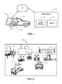
- FIG. 1depicts a communication scheme and data flow/exchange, specifically between a police vehicle with an onboard camera device and a police station;
- FIG. 2depicts the recognition of a plurality of “vehicle” shapes in a video frame of visual data
- FIG. 3depicts the recognition of various traffic signal shapes in a video frame of visual data
- FIG. 4depicts the recognition of a plurality of “people” shapes in a video frame of visual data
- FIG. 5depicts a processing flow chart for an analytics engine
- FIG. 6depicts a top view of a device that may be installed on top of a police vehicle, featuring at least one 360-degree spherical camera;
- FIG. 7depicts a bottom view of the device of FIG. 6 , receiving sound data, and various pictorial depictions of sound data that may be collected;
- FIG. 8depicts the transfer of video and pictorial data from the spherical camera of the device of FIG. 6 , including the receiving of video/pictorial data, and various exemplary depictions of visual data that may be collected and subsequently isolated;
- FIG. 9is a flow schematic of sound data that may be collected from one or more microphones, that is subsequently processed (audio signal processing) to isolate parameters of interest (for example, direction of a loud noise or gunshot detection), and subsequent related action(s) e.g. video recording trigger/emergency announcement in response to gunshot detection or changes to a 360-degree spherical camera via video angle software in order to determine the direction of a loud noise;
- audio signal processingaudio signal processing
- parameters of interestfor example, direction of a loud noise or gunshot detection
- subsequent related action(s)e.g. video recording trigger/emergency announcement in response to gunshot detection or changes to a 360-degree spherical camera via video angle software in order to determine the direction of a loud noise
- FIG. 10depicts data flow, specifically video data flow/exchange between a police vehicle with In Car Video (ICV) and Access Point (AP), that is further remotely controlling and exchanging information with various Body Worn Cameras (BWC) and other ICV units in other vehicles;
- ICVIn Car Video
- APAccess Point
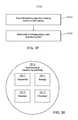
- FIG. 11depicts a Global Data Access System configuration
- FIG. 12in accordance with some embodiments of the present disclosure, is a flow chart depicting, at a top level, a method for triggering an action in response to capture and characterization of image data;
- FIG. 13in accordance with some embodiments of the present disclosure, is a flow chart depicting, at a top level, another method for triggering an action in response to capture and characterization of image data.
- FIG. 14in accordance with some embodiments of the present disclosure, depicts a portable camera device
- FIG. 15depicts the portable camera device of FIG. 1 in use as a body-worn-camera
- FIG. 16depicts a schematic of a portable camera device docked in a docking module
- FIG. 17depicts a vehicle with an onboard computer and camera devices
- FIG. 18depicts a processing flow chart for audio data processing
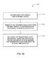
- FIG. 19is a flow chart depicting, at a top level, a method in accordance with some embodiments of the present disclosure.
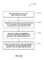
- FIG. 20is a flow chart depicting, at a top level, another method in accordance with some embodiments of the present disclosure.
- FIG. 21is a flow chart depicting, at a top level, another method in accordance with some embodiments of the present disclosure.
- FIG. 22depicts a system including an unmanned aerial vehicle (UAV), a docking station for a UAV, and a vehicle on which the docking station is mounted, wherein the UAV is docked in the docking station, in accordance with some embodiments of the present disclosure;
- UAVunmanned aerial vehicle
- FIG. 23depicts the system of FIG. 22 wherein the UAV is airborne, in accordance with some embodiments of the present disclosure
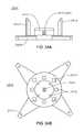
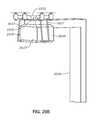
- FIGS. 24A and 24Bdepict perspective views of a UAV docking station, viewed from the front and top thereof, respectively, in accordance with some embodiments of the present disclosure
- FIG. 25is a block diagram showing a central body of a UAV docking station and internal components thereof, in accordance with some embodiments of the present disclosure
- FIGS. 26A-26Ddepict, in accordance with some embodiments of the present disclosure, multiple views of a UAV, with FIG. 26A showing a front view with arms closed, FIG. 26B showing a front view with arms opened, FIG. 26C showing a bottom view, and FIG. 26D showing a side view;
- FIG. 27is a block diagram showing a central body of a UAV and internal components thereof, in accordance with some embodiments of the present disclosure.
- FIG. 28depicts a scene in which a UAV is perching on a structure, in accordance with some embodiments of the present disclosure
- FIG. 29Adepicts a scene in which a UAV is perching on a structure
- FIG. 29Bis a close-up of the perched UAV, in accordance with some embodiments of the present disclosure
- FIGS. 30A and 30Bdepict multiple views of a UAV including an alternate camera system, with FIG. 30A showing a front view thereof and FIG. 30B showing a bottom view thereof, in accordance with some embodiments of the present disclosure;
- FIG. 31depicts a scene in which a UAV is perching on a structure, the UAV having an alternate perching mechanism, in accordance with some embodiments of the present disclosure
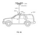
- FIG. 32depicts an alternate system including a UAV, a docking station for a UAV, and a vehicle on which the docking station is mounted, wherein the UAV is tethered to the vehicle/docking station, in accordance with some embodiments of the present disclosure
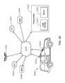
- FIG. 33depicts a system such as that of FIG. 23 but also including a communications network, in-car video camera devices of police vehicles, body worn cameras of police officers, and a server of police headquarters, all of the elements operable to communicate with one another via the communications network, in accordance with some embodiments of the present disclosure;
- FIG. 34depicts a scene including a system such as that of FIG. 23 , and also a police officer, a suspect vehicle and a suspect on the scene, with the UAV monitoring the scene, detecting a threat (suspect with weapon), and issuing an alert;
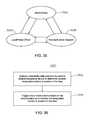
- FIG. 35depicts a state diagram showing control of a UAV by different parties and transfer of control among the parties, in accordance with some embodiments of the present disclosure
- FIG. 36is a flow chart depicting, at a top level, a method that may be performed by a UAV, a roof-mounted camera device, remote or cloud server, or other device, in accordance with some embodiments of the present disclosure
- FIG. 37is a flow chart depicting, at a top level, a method that may be carried out by a UAV system including a UAV and a docking station, in accordance with some embodiments of the present disclosure
- FIG. 38is a block diagram showing a central body of a roof-mounted camera and internal components thereof, in accordance with some embodiments of the present disclosure.
- FIGS. 39A and 39Billustrate an example of a physical interface and an electrical interface between a tether and a UAV, wherein FIG. 39A shows both the tether portion and the UAV portion of both the physical and electrical interfaces, and FIG. 39B shows the tether portion of the physical interface.
- the term “computer”encompasses special purpose microprocessor-based devices such as a digital video surveillance system primarily configured for executing a limited number of applications, and general purpose computers such as laptops, workstations, or servers which may be configured by a user to run any number of off-the-shelf or specially designed software applications.
- Computer systems and computer deviceswill generally interact in the same way with elements and aspects of disclosed embodiments.
- This disclosurealso refers to memory or storage devices and storage drives interchangeably.
- memory or a storage device/driverepresents a medium accessible by a computer (via wired or wireless connection) to store data and computer program instructions.
- use of the term “microprocessor” or “processor” in this disclosureencompasses one or more processors. (The term “microprocessor” may be used to refer to a processor or a microprocessor, and the term “processor” may be used to refer to a processor or a microprocessor.)
- multiplexand “multiplexing” refer to the incorporation or combination of a specified file, audio track (i.e. audio communication signal), and/or data with another file, audio track, or other data.
- video data and “visual data”refer to still image data, moving image data, or both still and moving image data, as traditionally understood. Further, the terms “video data” and “visual data” refer to such image data alone, i.e., without audio data and without metadata.
- image datain contrast to “still image data” and “moving image data” and “audiovisual data” are used to mean the same thing.
- audiovisual data(which may also be called “image data”) encompasses not only video or visual data but also audio data and/or metadata. That is, audiovisual data, or image data, may include visual or video data, audio data, metadata, or any combination of these three.
- video data and “visual data”may refer to such data that is a component of audiovisual data, where the audiovisual data may also contain audio data and/or metadata, and on the other hand the terms “video data” and “visual data” may refer to such data that is not a component of audiovisual data.
- audio datamay refer to such data that is a component of audiovisual data, where the audiovisual data may also contain video/visual data and/or metadata, and on the other hand the term “audio data” may refer to such data that is not a component of audiovisual data.
- Audiovisual or image datamay be compressed using industry standard compression technology (e.g., Motion Picture Expert Group (MPEG) standards, Audio Video Interleave (AVI), etc.) or another proprietary compression or storage format.
- MPEGMotion Picture Expert Group
- AVIAudio Video Interleave
- cameramay refer to devices configured to record or capture audiovisual data and/or to devices that record or capture solely video/visual data (i.e., not audio data and not metadata). Such devices may also be referred to as video recording devices, image capture devices, or the like. Metadata may be included in the files containing the audiovisual (or audio, or video) data or in separate, associated data files, that may be configured in a structured text format such as eXtensible Markup Language (XML).
- XMLeXtensible Markup Language
- Metadatarefers to information associated with the recording of audio, video, or audiovisual data, or information included in the recording of such data
- metadatamay contain information describing attributes associated with one or more acts of actual recording of audio, video, or audiovisual data. That is, the metadata may describe who (e.g., officer ID) or what (e.g., manual or automatic trigger) initiated or performed the recording.
- the metadatamay also describe where the recording was made. For example, location may be obtained using global positioning system (GPS) information.
- GPSglobal positioning system
- the metadatamay also describe why the recording was made (e.g., event tag describing the nature of the subject matter recorded).
- the metadatamay also describe when the recording was made, using timestamp information obtained in association with GPS information or from an internal clock, for example.
- Metadatamay also include information relating to the device(s) used to capture or process information (e.g. a unit serial number, Mac address, etc.). Metadata may also include telemetry or other types of data. From these types of metadata, circumstances that prompted the recording may be inferred and may provide additional information about the recorded information. This metadata may include useful information to correlate recordings from multiple distinct recording systems as disclosed herein. This type of correlation information may assist in many different functions (e.g., query, data retention, chain of custody, precise synchronization and so on).
- the metadatamay also include additional information as described herein, such as: location and size of an object of interest on screen, object's color and confidence level, vehicle make and confidence level, vehicle type and confidence level, license plate number/state (e.g., which of the 50 U.S. states) and confidence level, and number of pedestrians.
- additional informationsuch as: location and size of an object of interest on screen, object's color and confidence level, vehicle make and confidence level, vehicle type and confidence level, license plate number/state (e.g., which of the 50 U.S. states) and confidence level, and number of pedestrians.
- license plate number“license plate character,” and the like are all understood to encompass both numbers and other characters on a license plate.
- the term “portable”refers to the ability to be easily carried or moved.
- the termencompasses, without limitation, wearable devices (i.e., devices that can be worn or carried by a person or an animal).
- cloudrefers to an area or environment generally accessible across a communication network (which may or may not be the Internet) that provides shared computer storage and/or processing resources and/or data to computers and other devices.
- a “cloud”may refer to a public cloud, private cloud, or combination of a public and private cloud (e.g., hybrid cloud).
- public cloudgenerally refers to a cloud storage environment or area that is maintained by an unrelated third party but still has certain security measures in place to ensure that access is only allowed to authorized users.
- private cloudgenerally refers to a cloud storage environment or area that is maintained by a related entity or that is maintained on physical computer resources that are separate from any unrelated users.
- globalrefers to worldwide and the term “global access” refers to being available or accessible from anywhere in the world via conventional communication means (e.g. the communication network described herein).
- FIG. 1depicts an embodiment of this disclosure.
- a police vehicle 10is equipped with a computer 12 (which accordingly may be referred to as “vehicle 10 computer 12 ”) linked to a server 15 housed in a police station 14 via a communication network 18 (e.g., Internet, Cloud, radio network, Bluetooth, Wi-Fi, 3G, 4G, LTE, satellite, etc.).
- the computer 12is linked with a communications module that includes a (e.g., mobile) receiver 13 .
- the police vehicle 10may be a car, motorcycle, bicycle, aircraft, watercraft, or other transportation means.
- the police station 14may also house a memory storage bank 17 in addition to server 15 for data processing and communications.
- the vehicle 10is equipped with one or more camera devices 16 to capture image data from the real world.
- the camera device(s) 16may or may not be mobile.
- the camera device 16may also be configured with internal memory (e.g. hard disk) and/or coupled to a local or remote storage drive for recordation (in digital or analog format) of the collected information.
- Suitable camera devices 16that may be used to implement embodiments of this disclosure include the devices commercially available from COBAN Technologies Inc., in Houston, Tex. (http//www.cobantech.com).
- the vehicle 10 computer 12is configured to access one or more databases (onboard the vehicle 10 or remote via the communication network 18 ) containing a repository with detailed information and data of existing vehicles, structures, objects, people, etc.).
- databasesonboard the vehicle 10 or remote via the communication network 18 containing a repository with detailed information and data of existing vehicles, structures, objects, people, etc.
- an accessible databasemay be populated with data regarding parameters, shapes, other information relating to particular individuals, states and cities, vehicle identification parameters/characteristics (makes, models, colors, etc.), weapons data, etc.
- the database(s)can be updated as often as necessary.
- the computer 12may have access to databases and data repositories that are not available to the general public.
- the police station 14 memory storage bank 17houses the database accessed by the vehicle 10 computer 12 .
- the vehicle computer 12 microprocessoris configured with specific instructions to be carried out upon receipt of certain communications, such as Amber alerts, Silver alerts, etc., (via the communication network 18 ) from the police station 14 or other designated agencies or systems, such as the FBI, DEA, ATF, etc.
- certain communicationssuch as Amber alerts, Silver alerts, etc.
- law enforcement agenciesoften issue Be on Look Out (“BOLO”) alerts to bring to the attention of law enforcement officers key information regarding an occurrence or activity of high importance.
- Such alertstypically include a description with some known details and facts relating to a suspect or an item or event of interest.
- the officer who receives the BOLO alertis intended to keep an eye out for the suspect or item of interest by continually or periodically scanning his environment for the particular descriptive details of the suspect/item identified in the alert.
- the computer 12 microprocessoractivates the camera device 16 (if not already activated) to start collecting information and processing the captured image data to determine whether the specific content identified in the alert is present in the captured image data.
- the computer 12 microprocessoris configured to search the captured image data for the presence of the designated content according to the received alert or communication.
- the designated contentmay include information such as: a geographical parameter (e.g.
- GPS coordinatelocation data
- location datastreet designation, historic site, monument, etc.
- vehicle typeSUV, truck, sedan, motorcycle, etc.
- license plate number(s)particular objects (traffic lights, street signs, etc.), particular shapes (human, animal, etc.), or a person, e.g., with particular characteristics.
- the computer 12 microprocessorWhen an object enters the scene, the computer 12 microprocessor performs analytics on the captured image data using an analytics engine that references the accessed database(s), and the analytics include creating snapshots and character scanning, optical character recognition (OCR), pixel scanning, and shape/pattern recognition analytics to analyze and search the captured data for the presence of images matching the designated content.
- the analytics softwaremay also analyze a scene, tracking identified objects of interest, for example, a police officer's movements. For example, if an officer falls and becomes horizontal for a certain amount of predetermined time, the microprocessor can send an alert to police dispatch through the communication network 18 so that dispatch can call via radio or cell phone to check on the fallen officer.
- the shape/pattern detection analyticsmay also be used to detect objects already in or coming into the scene, such as a person walking or running, and also to detect the direction of travel of such objects. It may also be used to detect objects or people approaching the officer based on changes in the detected measured distance between the officer and person/object, and based on this analysis, the microprocessor can send an alert to the officer on the scene (e.g., via radio, 3G/4G wireless networks, or Body Worn Camera (BWC) speaker over Wi-Fi or Bluetooth®).
- BWCBody Worn Camera
- Additional features that may be provided by the analytics engineinclude automatically marking image data if a crash was detected in the background of the scene, such as a vehicle rolling or flipping.
- Yet another aspect of the shape/pattern detection features provided by the analytics engineis the determination of a weapon threat.
- the scenecan be scanned for the detection of objects such as potential weapon types like guns, knives, etc., being held in a person's hand or for various threatening stances by a potential adversary such as detecting when the adversary is standing, squatting sideways, running, etc.
- the detection/analytics capabilities of the disclosed embodimentsalso include the ability to scan the entire or specified area of a scene for any movement. For example, if an officer is parked somewhere filling out a report and looking down, if the system detects movement an alert sound or message on a display (e.g. the vehicle display) can notify the officer to be aware. With multiple viewing angles, the alerts can also notify the officer which direction the movement came from by using distinct sounds for each direction such as front, rear, right side or left side, voice notification of the direction and/or notification messages on the display. The system can also notify the officer if it is a vehicle, person, or an unknown object and if the object is moving fast or in a threatening manner. Such embodiments may incorporate the camera/microphone unit 16 described below with respect to FIGS. 6-8 .
- FIGS. 2-4depict scenes as processed by the computer 12 microprocessor to detect various shapes and objects according to embodiments of this disclosure.
- FIG. 2depicts the recognition of multiple vehicle shapes (shown in and above bounding boxes) 21 in a video frame 20 of the information captured by a camera device 16 . This data may be used, e.g., to detect a vehicle of interest.
- FIG. 3depicts the recognition of various traffic signal shapes (shown in bounding boxes) 31 in a video frame 30 of the information captured by a camera device 16 . The detection of such real-world features can be used to provide additional location data.
- FIG. 4depicts the recognition of multiple “people” shapes (shown in bounding boxes) 41 in a video frame 40 of the information captured by a camera device 16 . Such data may be used to implement the applications related to officer safety or behavior patterns as disclosed herein.
- the analytics engineproceeds to another step of further analyzing the data containing the designated content to detect for the presence of one or more designated details or attributes of or associated with the designated content.
- a communicationmay be received by the receiver 13 (such as a BOLO, Amber, or Silver alert), designating the content to search for as a car, and the attributes as a silver Audi A6 sedan.
- the analytics enginewill scan and search the captured image data for a match of the descriptor, i.e., the car.
- the analytics enginedetects the presence of a car in the captured image data, the data is then further analyzed to determine if the designated attributes (i.e., vehicle make—Audi, vehicle model—A6, color—silver, vehicle type—sedan) are present in the data.
- designated attributesi.e., vehicle make—Audi, vehicle model—A6, color—silver, vehicle type—sedan
- Other possible designated attributesinclude, for example: state identifiers (e.g., license plate numbers, characters, emblems, mottos, etc.).
- the computer 12 microprocessorcontinually writes all metadata/attribute information associated with the detected designated content to a text or XML file. It will be appreciated that the designated content descriptors and associated designated attributes may comprise an unlimited variety of items and descriptors, as exist in the real world. The embodiments of this disclosure are not to be limited to any specific content or attribute of such content.
- the analysisfurther includes the determination of a confidence level or criterion for the designated attribute(s).
- Modern processorsprovide the ability for high-speed analysis of vast amounts of data. Physical dimensions and parameters of real-world objects represent factual data that can be mathematically measured, analyzed, and compared. For example, the length, width, and height of a vehicle of a given make and model represents factual data.
- the analytics engine analysis of the collected dataentails a breakdown of the captured images into data points or pixels that are then analyzed to determine respective spacing and dimensions, which can then be compared to the real-world parameters in the database library of existing items.
- the analytics enginedetects a vehicle in the image data, it then performs further analysis to detect for the color silver based on a pixel hue analysis, it may then continue the analysis to mathematically define the dimensions of the detected vehicle for comparison against the actual Audi A6's dimension parameters stored in the database. If a match or near match is found between the dimensions of the detected car and one of the A6 models in the library, the engine then calculates a probability factor representing a confidence level for the match and compares that to a criterion for equivalence or matching of the detected object and the object stored in the database.
- the analytics enginewould determine a positive result and proceed with triggering an action as described for the disclosed embodiments.
- the criterion of equivalence for an affirmative match result for a license plate numbermay be set at 55% or better, to allow for instances when only a partial plate number is decipherable from the captured image.
- the analytics enginecan bypass this database query and perform a character-recognition analysis.
- the database available to officerswill likely contain all available information relating to data such as a license plate number.
- the criterion of equivalence for an affirmative match resultmay be based on a probability factor from a combination of analyzed attributes.
- the analytics to determine a confidence level or criterion for the designated attribute(s)are based on a deep learning algorithm.
- the computer 12may be configured with software providing a deep learning analytics engine. Defined shapes and movement rules, multiple images of vehicle types, make, model, etc., can be input and stored in the deep learning engine at different viewing angles, distances, various lighting conditions, etc. The captured image data can be compared against the engine contents to provide a data output with a percentage of confidence of accuracy for its attributes to trigger an action as described herein.
- the analytics and rulescan be applied to any object (e.g., pedestrians, animals, street signs, etc.).
- the analytics for recognition and detection of the designated contentis distributed among the vehicle 10 computer 12 and one or more remote computers (e.g. the server 15 in the police station 14 ).
- the server 15may be configured to generate a neural net object model for the vehicle 10 computer 12 .
- the vehicle 10 computer 12can also be configured to use a separate neural network to instantly achieve multiple object recognition as described herein.
- the vehicle 10 computer 12 and the remote computer(s)can communicate and exchange data via the communication network 18 .
- the vehicle 10 computer 12 and/or the remote computer(s)e.g. server 15
- AIartificial intelligence
- the analytics engineis configured to detect unknown objects (e.g. a modified vehicle). This data can be locally stored for later upload or immediately transmitted to another location (e.g. to server 15 ) for verification and/or classification to aid in the training of detection of objects by the detection engine.
- this type of classificationcan be done in or near real-time on the edge device such as an in-car video unit or a wearable device such as a body worn camera.
- an “edge” devicegenerally refers to a device used or located at a point of interest.
- an edge deviceis considered an on-scene device. It will be appreciated by those skilled in the art that embodiments of this disclosure may be implemented using conventional software platforms and coding configured to perform the techniques as disclosed herein.
- the microprocessortriggers an action.
- the triggered actionmay include:
- FIG. 5depicts a processing flow chart for an analytics engine 50 embodiment in accordance with this disclosure.
- the receiver 13 in the vehicle 10receives the communication indicating the designated content to search for, along with the known attribute(s) associated with the designated content.
- the vehicle computer 12processes the instructions and the microprocessor commences the scanning analysis.
- the analysisentails a data feed 56 of the image data from the linked camera device(s) 16 to the computer 12 microprocessor.
- the data feed 56 from the camera device(s) 16 to the computer 12may be wireless or via cabling (e.g. using a wired onboard vehicle camera).
- the computer 12may be configured to automatically activate the linked mobile camera device(s) 16 to start collecting image data, if the device(s) is/are not already activated.
- Module 54also comprises linking with a database 58 to perform the analysis of the collected image data.
- the database 58may be resident in the vehicle 10 computer 12 or remotely located (e.g. the police station 14 memory storage bank 17 ) and accessed via the communication network 18 .
- the analysiscontinues with a scan of the image data captured by the camera device(s) 16 to detect for the presence of the designated content. If the designated content is not detected in the captured image data, module 60 entails a return to module 54 and the analysis continues with the scanning of additional image data collected by the camera device(s) 16 .
- module 62the image data containing the detected designated content is further analyzed to determine if the data comprises the designated attribute(s) conveyed in the communication. If the designated attribute(s) is/are not detected, module 62 entails a return to module 54 and the analysis continues with the scanning of additional image data collected by the camera device(s). If the designated attribute(s) is/are detected, the flow proceeds directly to module 66 , or in some embodiments to an additional (optional) module 64 . If proceeding directly from module 62 to module 66 , the computer 12 microprocessor triggers an action as previously described.
- the image data containing the detected designated attribute(s)is further analyzed to determine if the attribute(s) meets the designated criterion, as described above. If the attribute(s) meets the designated criterion, the flow proceeds to module 66 and an action is triggered. If the attribute(s) does not meet the designated criterion, module 64 entails a return to module 54 and the analysis continues with the scanning of additional image data collected by the camera device(s) 16 .
- the computer 12can process multiple searches relating to multiple incoming communications, performing the respective scanning/analysis on the captured image data. The collection and processing of image data may be stopped and started as desired by a user (e.g.
- a commande.g., a voice command or a command that is typed/keyed/entered by touchpad
- a button on the computer 12 or on a BWC 29or by another incoming communication (e.g. from the alert dispatching source) instructing the computer 12 to cancel or start/resume the particular search/analysis.
- the computer 12resumes scanning all available image data captured in the scene until another communication is received to trigger another action (e.g. another alert) or the officer manually enters a different instruction.
- the computer 12may also be configured to automatically clear an alert after running a scan without a match for a predetermined time or when the vehicle 10 is housed or turned off (e.g. when a patrol car is parked at the police station at the end of a shift).
- embodiments of the analytics engine disclosed hereinmay be implemented using any suitable computer platforms and coding as known in the art.
- the camera device and detection/analytics enginemay find an object or person of interest that a police officer didn't notice. For example, a police officer may be driving down the street when a BOLO is issued for the silver Audi sedan. The officer may be focusing on driving or performing some other activity/task and may not see the item of interest, in this case the disclosed systems can alert multiple officers to be aware of the potential object of interest and thereby improve the chances for detection. This can also increase safety and efficiency for the officer. Officer efficiency may also be improved with embodiments wherein the camera device and detection/analytics engine are configured to detect expired vehicle tags.
- the microprocessorcan trigger an action as described above (e.g., flash an alert on the vehicle display, issue a notice to the police station 14 , record the information as metadata, etc.).
- the disclosed embodimentsprovide the means to perform the described detection and analytics techniques in real-time, as image data is being captured.
- FIG. 6an overhead view of a camera device 16 comprising a spherical camera that may be used with implementations of this disclosure is depicted.
- the camera device 16is configured for roof-mounting on a vehicle 10 and provides a 360-degree view.
- FIG. 7depicts the bottom view of the spherical camera device 16 , showing (more fully than in FIG. 6 ) a series of directional microphones (1-4). With the directional microphones (1-4), the approximate direction 8 of sounds emanating from a sound source 9 can be detected.
- the computer 12 microprocessorcan be configured to automatically mark points in the captured video data at which specific sounds 5 are detected (as depicted in FIG.
- FIG. 9depicts a schematic flow chart 70 of a spherical camera device 16 as used in combination with the microphones (1-4) to capture and process the detection of gun shots.
- the audio data captured by the microphones (1-4)is processed to determine the approximate direction of the sound source 74 .
- the spherical camera device 16 software controladjusts the camera to capture image data in the approximate direction of the sound source. If the audio processing determines that the sound source was a gunshot 78 , a gunshot detection signal is sent to trigger the camera device(s) 16 to start recording and an emergency announcement, or actionable notification, or request, is sent via the communication network to the police station 14 or to other nearby devices (step 80 ).
- Other embodiments of this disclosuremay be implemented with other types of camera devices 16 besides a spherical camera (e.g., using a conventional multi-image sensor camera), to provide the desired image clarity and depth of field.
- the embodiments of this disclosuremay be implemented to incorporate in the described recognition analytics any conventional or future developed sensors providing other types of data besides image/video/audio data (e.g. distance measuring sensors, etc.).
- the vehicle 10 computer 12 microprocessormay also be configured with instructions to send out a communication (via the communication network 18 ) to activate the camera devices 16 in other law enforcement vehicles (e.g., in-car video (ICV) units 28 ), and the BWCs 29 worn by officers, within a set range or perimeter of where the object of interest (corresponding to the designated content) was detected, as depicted by the arrows in FIG. 10 .
- a communicationvia the communication network 18
- the vehicle 10 computer 12 microprocessormay also be configured with instructions to send out a communication (via the communication network 18 ) to activate the camera devices 16 in other law enforcement vehicles (e.g., in-car video (ICV) units 28 ), and the BWCs 29 worn by officers, within a set range or perimeter of where the object of interest (corresponding to the designated content) was detected, as depicted by the arrows in FIG. 10 .
- IOVin-car video
- an autonomous vehicle 10to scan the scene for the object attributes in a received communication (e.g. a BOLO alert) and to send a notification to officers nearby and/or to a police dispatch center.
- the vehicle 10can track the detected vehicle or person providing real-time or historical location data updates to the officers responding and/or to a police dispatch center. This could help the officers more accurately pursue the vehicle or person of interest.
- BWCscan be used with implementations of the embodiments of this disclosure.
- Suitable BWCsinclude the devices commercially available from COBAN Technologies Inc., in Houston, Tex. (http//www.cobantech.com).
- the BWCsare worn by officers on patrol.
- the BWCcan be conveniently clipped to the officer's uniform or body gear as desired.
- BWCsmay also be configured with a microphone to collect audio data.
- the collected audio datamay be transmitted together with the captured image/video and/or metadata to another device (e.g., located in a police car, at a police station, on another police officer, or in the cloud) as described herein.
- another devicee.g., located in a police car, at a police station, on another police officer, or in the cloud
- the vehicle 10 computer 12may be configured to perform wireless networked or distributed analytics processing. As previously described, in some embodiments the vehicle 10 computer 12 is configured to access an onboard database and perform the disclosed analytics processing as a stand-alone unit. In other embodiments, the vehicle 10 computer 12 may be configured to communicate via the communication network 18 (e.g. using the cloud) with other computers (e.g. remote ICV units 28 and BWCs 29 ) to perform a distributed and shared image data analysis. With reference to FIG. 10 , the vehicle 10 computer 12 microprocessor may issue a communication to the ICV units 28 in police vehicles and BWCs 29 within a set range, to not only activate the respective camera devices, but also including selected image data information to activate the remote devices to perform a local analysis.
- the vehicle 10 computer 12 microprocessormay issue a communication to the ICV units 28 in police vehicles and BWCs 29 within a set range, to not only activate the respective camera devices, but also including selected image data information to activate the remote devices to perform a local analysis.
- the microprocessorsends a communication (in real-time) to all other units/officers within the set range, including the captured image data or components of the captured image data (e.g. metadata alone; each of video data, audio data, and metadata is considered a component of the captured image data).
- the ICVs 28 and BWCs 29 receiving the informationcan then focus on scanning to detect for the other vehicles described in the alert.
- image data captured by the ICVs 28 and BWCs 29can be relayed back to the vehicle 10 computer 12 via the communication network 18 for hubbed real-time processing.
- the ICVs 28 and BWCs 29are used to form a virtual net providing real-time processing and communication.
- the communication network 18e.g. the cloud
- the communication network 18provides a relay data point for all ICVs 28 , BWCs 29 , vehicles 10 , and any other wirelessly linked devices or systems in the vicinity where events of interest are occurring, as well as a relay data point to or from remote locations.
- This networkprovides for vehicle-to-vehicle and system-to-system distributed communications.
- the communication loop in such embodimentsmay also include the police station, dispatch headquarters, and other law enforcement agencies.
- the ICV 28is configured to detect and take snapshots, or receive snapshots from a wearable device (e.g. BWC 29 ), of a person's face to run facial recognition locally or by transmitting the data to a remote server (e.g. server 15 ) for further analytics.
- a BOLOmay include an alert to look for a white male, wearing a black jacket, having an age in the mid-twenties, etc.
- the detection of attributesis also enhanced, such as detection of approximate age, gender, and race.
- the use of AI software and other advanced software applicationsmay provide additional benefits.
- Some embodimentsmay also be configured to receive video data via transmission such as Real Time Streaming Protocol (RTSP) streaming for detection and analytics of attributes and facial recognition.
- RTSPReal Time Streaming Protocol
- an authorized user linked to the computer 12 microprocessor via the communication network 18can analyze the information according to specific criteria established by the user. For example, a user can select or draw an area on a map to display vehicles in a given region, along with their associated data such as specific location data/time/number of recorded events/event type/duration, license plate data, vehicle type, shape, color etc.
- the usercan select an option to send a request to any or all vehicle computers 12 to scan their storage drives, that are continuously recording, for the desired information and send back a response with the search results or to retrieve the designated data with time markers of start and stop points to export video, snapshots, or metadata.
- This embodimentcan be implemented for a local or global application.
- FIG. 11depicts another embodiment of this disclosure.
- a computer server 26is linked to one or more camera devices 16 (e.g. ICV units 28 and BWCs 29 ) via the communication network 18 .
- Some embodimentsmay also incorporate fixed camera devices 16 (e.g. cameras on buildings, light poles, etc.).
- This embodimentprovides for shared Global Data Access and distribution, allowing authorized users 27 to access the server 26 via the communication network 18 .
- the server 26provides a centralized repository for the specific data and information of interest to a user group (e.g. law enforcement agencies). Using such a globally shared server, authorized users 27 can send data of interest to the server 26 for storage (e.g., in local memory or linked data storage).
- the server 26may be partially or entirely implemented as a virtual server in the cloud. Such cloud computing embodiments offer flexibility of scalability.
- the server 26is also configured to analyze the data sent to it (encompassing audio, video, metadata, and/or any other available telemetry) by an authorized user in the group, or captured by the linked mobile device(s) 16 , to analyze and search for the presence of designated content and designated attributes in the data, as described herein.
- the server 26may also be configured to perform full or partial analytics on the captured image data and the data sent by authorized users.
- the data stored in the server 26could remain available for a defined period to allow authorized users access to the data.
- an application on the server 26can scan the stored data (including stored metadata) and if an attribute of interest is detected the application can generate a request to be sent to the linked camera device 16 that captured the detected image data to mark configurable in (start) and out (stop) points of the recorded video, audio, metadata, etc.
- the marked image datacan also be exported and/or uploaded or a live stream can be started if the camera device is still near the location where it originally captured the data. If high importance image data is detected, the server 26 can send alerts or emails to users of the Global Data Access System.
- the Global Data Access System server 26sends a command, via the communication network 18 , to any linked camera device 16 to analyze its recorded image data to search for matching audio, video, and/or metadata, as the case may be. If a match or near match is found, the device that found the match or near match notifies the server 26 , and the detected matching or near matching image data, or components thereof (e.g. metadata), are then uploaded and saved (e.g.
- the server 26may also be configured to send a notice (e.g. via email) to the searching agency or others, regarding the detected data.
- the server 26may be configured to perform the image data analysis on real-time image data being collected by any linked camera devices.
- the server 26may also be configured to analyze the data stored in memory and/or captured by the camera device(s) 16 according to criteria established by an authorized user 27 having access to the server 26 via the communication network 18 (e.g. in response to a BOLO alert).
- FIG. 12is a flow chart depicting a method 100 according to an embodiment of this disclosure.
- a wireless communicationis received with a receiver, indicating designated content to search for in image data.
- the communicationmay be conveyed via the communication network 18 .
- image datais obtained using at least one camera device 16 (e.g., ICV 28 , BWC 29 ) configured to capture image data.
- camera device 16e.g., ICV 28 , BWC 29
- step 130using a microprocessor linked to the receiver and the at least one camera device, (a) the obtained image data is analyzed to determine if it contains the designated content and (b) obtained image data containing the designated content is analyzed to determine if it contains at least one designated attribute associated with the designated content. This may be implemented using an analytics engine and processing as described herein.
- an actionis triggered by the microprocessor if the at least one designated attribute is detected in the obtained image data containing the designated content. This entails any of the actions that may be triggered by the micro
- FIG. 13is a flow chart depicting a method 200 according to an embodiment of this disclosure.
- a computer serveris linked via a communication network to at least one camera device 16 (e.g., ICVs 28 , BWCs 29 ) configured to capture image data.
- camera device 16e.g., ICVs 28 , BWCs 29
- image data captured by the at least one camera deviceis analyzed for the presence of designated content
- captured image data containing the designated contentis analyzed for the presence of at least one designated attribute associated with the designated content. This may be implemented using an analytics engine and processing as described herein.
- the captured image data or components of the captured image data, containing the at least one designated attributeare uploaded for storage.
- a notice relating to the captured image data or to the components of the captured image datais sent via the communication network.
- the term “record”is interchangeable with the term “store” and refers to the retention of data in a storage medium designed for long-term retention (e.g., solid state memory, hard disk, CD, DVD, memory card, etc.), as compared to the temporary retention offered by conventional memory means such as volatile RAM.
- the temporary retention of data, audio data or otherwiseis referred to herein as the “holding” of data or as data being “held.”
- FIG. 14depicts an embodiment of a first device 110 in accordance with this disclosure.
- the first device 110comprises a portable wearable camera 112 .
- the camera 112is configured with a fixed-focus or auto-focus lens 116 , a microphone 118 , and a record activation button 120 , which permits a user to manually activate or deactivate the camera 112 to record audiovisual data (i.e., audio data captured via the microphone 118 and video data captured via the lens 116 ).
- Some embodimentsmay be configured to allow for separate manual activation/deactivation of the microphone 118 (audio recording functionality) and lens 116 (video recording functionality), respectively, permitting a user to capture only audio data or only video data as desired.
- camera 112is configurable/operable to record/store/hold solely audio data, solely video data, or a combination thereof, which may be referred to as audiovisual data; in all of these cases, camera 112 is also operable/configurable, but not required, to record/store/hold metadata. As described below, where audiovisual data is recorded/stored/held, this may be with or without a separate audio and/or video track. Some embodiments may also include a programmable function button 121 that provides a user the ability to select among different programmed/programmable modes of operation.
- the camera 112may be configured with an internal buffer 122 (e.g. RAM) to temporarily hold captured audio, video and/or audiovisual data, and memory 124 (e.g.
- the camera 112may be configured to automatically create the respective data files (i.e. audio, video, audiovisual) as the data is captured/recorded.
- Some embodimentsmay also include an audio speaker 125 to provide voice messages and/or an audible indication during various modes of operation.
- the speaker 125may be configured for activation: when camera 112 recording starts or stops, to provide a camera low battery alert, to provide a camera memory full alert, to indicate successful camera pairing with another device, to provide warning beeps that may be sent from another device, etc.
- the audible indicationmay indicate generically an event or may indicate the specific event (not merely that one of several types of events occurred).
- different audible soundsmay be generated for respective different event types (e.g., one beep for event type x, two beeps for event type y; a buzzer sound for event type x, a ring tone for event type y, a voice message for event type z; a voice message for event type x, a different voice message for event type y; etc.).
- event typese.g., one beep for event type x, two beeps for event type y; a buzzer sound for event type x, a ring tone for event type y, a voice message for event type z; a voice message for event type x, a different voice message for event type y; etc.
- camera 112 embodiments of this disclosurecan be implemented with various types of additional sensors to capture/store desired information (e.g. temperature) and with conventional data storage means as known in the art.
- Embodiments of the camera 112are also equipped with internal Bluetooth® circuitry and associated electronics or other wireless technology to permit wireless communication and or signal transfer to or from the camera 112 .
- Bluetooth® pairingmay be manually activated by a button 126 on the camera 112 .
- Some embodimentsmay also include a light-emitting diode (LED) 127 to indicate when the camera 112 is recording or performing other functions.
- Some embodimentsare also equipped with Global Positioning System and real-time clock circuitry 128 to provide GPS data and current time information.
- Suitable camera devices 112that may be used to implement embodiments of this disclosure include the devices commercially available from COBAN Technologies, Inc., in Houston, Tex. (http//www.cobantech.com).
- FIG. 15depicts the first device 110 camera 112 being worn by a user 130 (e.g. a police officer) as a BWC.
- a user 130e.g. a police officer
- This implementationprovides a user the ability to capture on-scene audiovisual data with the camera 112 .
- the wearable camera 112provides the officer complete freedom to move while the camera 112 records audio, video, or audiovisual data as desired.
- the audio, video, and/or audiovisual datais stored in the camera 112 memory 124 .
- the camera 112may be configured to automatically include metadata (e.g., time stamp, watermark, GPS data, unit ID, officer ID, unique identifier, etc.) in the data recorded.
- metadatae.g., time stamp, watermark, GPS data, unit ID, officer ID, unique identifier, etc.
- the first device 110 camera 112may be configured to wirelessly sync (e.g., via Bluetooth®, RuBee, Wi-Fi, 3G, 4G, LTE, etc.) with other data gathering/telemetry devices within a set range or proximity.
- Such other devicesmay include, for example, biometric data sensors, geospatial, distancing and orientation data devices (apart from that provided by GPS), environmental telemetry devices, etc.
- the camera 112can wirelessly receive data transmitted from the other devices and store the data in memory 124 as metadata.
- the data from the other devicescan be recorded in sync with the recording of audio/video or independently (e.g. when the camera 112 is not holding/storing audio/video).
- the camera 112may be configured to sync with other devices automatically or via manual activation. All of this additional data from other devices can be multiplexed and synchronized with selected data using the techniques disclosed herein.
- the audio, video, and/or audiovisual data captured by the camera 112is temporarily held in the buffer 122 in a continuous circulating stream to perform “pre-event” circular buffering, without storing the data to memory 124 until the camera 112 is activated to store the data to memory 124 by a wireless command or by manual activation via the record “on/off” button 120 .
- This “smart buffering” featureprovides a circular buffer that temporarily holds the captured data in configurable file segment sizes (e.g., 1-5 minute chunks) until activated to store the data to memory 124 or the data is automatically deleted as new data is captured and streamed into the buffer 122 in a continuous manner. When activated to store the data, time points are marked in the data files.
- the camera 112can be configured to export the data (in the above-mentioned file segments) to a removable media and/or a separate folder in the memory 124 sector where the circular recording is written.
- the pre-event bufferingcan optionally be configured to continually write directly to memory 124 in a circulating stream.
- Suitable docking modules 132that may be used to implement embodiments of this disclosure include the devices commercially available from COBAN Technologies, Inc., in Houston, Tex. (http//www.cobantech.com).
- the docking module 132can be mounted in a police vehicle 134 , as depicted in FIG. 17 .
- Embodimentscan be implemented with the docking module 132 disposed on any type of vehicle.
- the docking module 132is coupled to a second device 136 comprising an in-car video (ICV) camera 140 that is disposed in the vehicle 134 .
- the ICV camera 140is configured to record on-scene audio, video, or audiovisual data.
- the audio, video, and/or audiovisual data captured by the ICV camera 140is stored on internal and/or removable storage media.
- the ICV camera 140is configured to temporarily hold the recorded audio, video, and/or audiovisual data in a buffer in a continuous circulating stream to perform “pre-event” circular buffering, without storing the data until triggered to store the data by a command signal or by manual user activation. Similar to the “smart buffering” feature provided by some embodiments of the first device 110 camera 112 , this feature also provides a circular buffer that temporarily holds the captured data in configurable file segment sizes (e.g., 1-5 minute chunks) until the ICV camera 140 is activated to store the data to memory or the data is automatically deleted as new data is captured and streamed into the buffer in a continuous manner. When activated to store the data, time points are marked in the data files.
- configurable file segment sizese.g., 1-5 minute chunks
- the ICV camera 140can be configured to export the data (in the above-mentioned file segments) to the removable media and/or a separate folder in the memory sector where the circular recording is written.
- the pre-event bufferingcan optionally be configured to continually write directly to memory in a circulating stream.
- the first device 110 camera 112can be used to record desired audio data (whether the audio is captured as audiovisual data or solely as audio data).
- the ICV camera 140will capture relevant audio data via a wired or wireless microphone source, while in some situations the ICV camera 140 may not (e.g., when the officer is outside of the vehicle 134 performing a traffic stop), and the first device 110 camera 112 may record the on-scene audio data when worn by the officer as a BWC.
- on-scene video data and audio dataare obtained by both the ICV camera 140 and the first device 110 camera 112 .
- separate playback of the recorded data files from the ICV camera 140 and the first device 110 camera 112may not be in sync. This mismatch in synchronization may be particularly exacerbated when the ICV camera 140 and the first device 110 camera 112 are each activated at different times or intermittently during a recording event.
- the embodiments of this disclosureprovide a solution in this situation.
- Embodiments of the second device 136are implemented with software configured to extract and/or multiplex the audio data recorded by the first device 110 with the file container of the data file(s) in the second device 136 memory (e.g. ICV camera 140 ).
- the data file(s) stored in the second device 136may include audio, video, metadata, and/or audiovisual files.
- Some embodiments of the second device 136are configured to multiplex the audio data recorded by the first device 110 to synchronize the audio data with the relevant data file(s) (i.e., audio data, video data, metadata, and/or audiovisual data) in the file container of the second device 136 .
- data filescan be multiplexed and synchronized with multiple devices 110 , 136 and other audiovisual sources, and in some cases linked to several devices and/or sources, that were on the scene, for later synchronization.
- Such embodimentsprovide for enhanced audio and video data review and may also be used to identify and create a map of the location where the devices/sources were located during an event.
- FIG. 18depicts a flow chart 150 of the audio data processing according to some embodiments of this disclosure.
- the first device 110 camera 112records audio data.
- the audio datamay be captured in an audiovisual recording or solely as an audio data recording.
- the recorded audio datais uploaded or transferred to the second device 136 (e.g. ICV camera 140 ).
- the docking module 132is configured with POGO pins that mate with a receptacle in the first device 10 camera 112 to facilitate the data transfer between the camera 112 and the second device 136 when the camera 112 is docked in the docking module 132 .
- the first device 110 camera 112is configured to wirelessly transfer the audio data file to the second device 136 using a conventional communication standard (e.g., RuBee, Wi-Fi, 3G, 4G, LTE, etc.). In yet other embodiments, the first device 110 camera 112 is configured for direct transfer of the audio data via a cable connection (e.g. a USB direct connect) with the second device 136 .
- the second device 136analyzes the transferred audio data and one or more data files in the second device's 136 file container to search for and detect markers present in the respective data.
- the camera processoris configured to execute instructions to analyze the audio data transferred from the first device 110 and the file container data file(s) (e.g., containing audio, video or audiovisual data) captured by ICV camera 140 .
- the markersmay consist of: the time stamps, a watermark, other metadata such as unit ID, officer ID, a unique identifier (“event identifier”) for the recording event (e.g., DUI, speeding, etc.), GPS data, telemetry, etc. These markers may be automatically embedded in the respective recorded data and/or a separate XML file by the portable camera 112 and the ICV camera 140 .
- Customized or event-specific markerscan also be added to the data by the officer by (e.g., manual) entry via an ICV camera 140 touch display 142 , a keyboard, a smartphone, or a tablet device. These added markers can be automatically associated with any device/file that is to be synchronized.
- Some portable camera 112 embodimentsmay also be configured with software to allow a user to add customized/event-specific markers to the camera 112 audio data file.
- customized/event-specific markersmay be preprogrammed and selectable via the programmable button or the aforementioned methods.
- Clock synchronization between the first device 110 and the second device 136may be performed by the GPS circuitry/clock 128 , by direct sync via the USB connection to the second device 136 , or by sending real-time clock (RTC) sync signals similar to Network Time Protocol (NTP) time servers.
- RTCreal-time clock
- the audio data transferred from the first device 110 camera 112is multiplexed and synchronized with the data file(s) in the second device ICV camera 140 file container.
- the data filesare multiplexed by linking the files together (via the software) such that opening or “playing” one file simultaneously opens/plays the linked file.
- the synchronizationis performed by: (a) selecting one of the data files (i.e., either the transferred audio data file or a data file in the ICV camera 140 file container); (b) rolling back in the selected file to a specific marker point (e.g.
- an officercan record the on-scene audio with the portable camera 112 affixed to his vest as a BWC. After the event is over, the officer can immediately transfer the audio data recorded with the camera 112 to the ICV camera 140 , as described herein, or the officer can perform the data transfer at a later time (e.g. upon return to the station at the end of his shift).
- the ICV camera 140can roll back the transferred audio data to the proper time stamp and automatically multiplex and synchronize the data files by marking points in the transferred audio data where the markers match the data in the audiovisual file stored in the ICV camera 140 .
- the ICV camera 140may create a unique identifier to identify the multiplexed data so that the synchronized data files can be logged in an audit trail and stored as desired. This way, when either data file is searched (i.e. the audio data recorded with the portable camera 112 or the data recorded with the ICV camera 140 ), the associated data file is automatically linked to be played back simultaneously and in sync if needed. Synchronous play from multiple data files can then be activated as desired. It will be appreciated by those skilled in the art that embodiments of this disclosure may be implemented using conventional software platforms and coding configured to perform the techniques and processes as disclosed herein.
- the synchronization step of module 158may be performed in a slightly different manner.
- the selected data file that is rolled back (step (b) above)is the data file with the shortest recording time, in this scenario the files may get synchronized starting points while maintaining the original starting points for each file. This ensures that the multiplexed data files are synced to the longest event of interest.
- the first device 110is configured to simultaneously record and transmit audio data to the second device 136 .
- the received audio transmissioncan be recorded in the second device 136 in real-time.
- an embodiment of the first device 110 camera 112could be used to record audio data as described herein, and simultaneously transmit (e.g., via RuBee, Wi-Fi, 3G, 4G, LTE, etc.) the audio data to a ICV camera 140 .
- the ICV camera 140can then store the transmitted audio data in the file container of the ICV camera 140 data file. Once stored in the ICV camera 140 , the transmitted audio data may be multiplexed and synchronized with the data file(s) in the ICV camera 130 as disclosed herein.
- the audio data transferred from the first device 110is used to replace audio data in a data file in the second device 136 .
- the system softwaremay be configured to automatically replace the poor-quality audio data in the data file from the ICV camera 140 with the audio data recorded by the first device 110 .
- only portions of audio data in the second device 136 data fileare replaced in this manner.
- the audio data transferred from the first device 110is established as the audio data for the data file in the second device 136 , such that when the multiplexed files are played, the only audio signal heard is that from the transferred audio data.
- the audio data recorded with first device 110may be used as the audio data once the audio data is multiplexed into the file container of the second device data file.
- Other embodimentsmay combine and synchronize audio data captured by a separate body-worn source (e.g., a separate body-worn wireless microphone linked to the second device 136 ) with audio data from the first device 110 , to produce a higher quality resultant audio file.
- Embodiments of this disclosurealso encompass the multiplexing and synchronization of data (audio, video, audiovisual) obtained by multiple first devices 110 and/or second devices 136 . Such embodiments provide for the synchronization of multiple audio data files to non-audio carrying video.
- any marker or combination of markers in the data filesmay be used to synchronize the data sets.
- the second device 136 that receives the recorded audio data from the first device 110is a remote computer (e.g. a server at headquarters), a smartphone, a wearable device (e.g. another BWC), etc. Any of these second devices 136 may be implemented with electronics, microprocessors, and software configured to perform the techniques and processes disclosed herein. It will also be appreciated that the first device 110 may be, or include, a device configured to record and/or transmit audio data and metadata, and optionally video data.
- the first device 110is configured to create and store an audio track (i.e. containing solely a captured audio communication signal).
- the audio trackcan be created as a solely recorded file, i.e., without the creation of visual data, or simultaneously with creating and storing a separate audiovisual track, or non-simultaneously with creating and storing an audiovisual track.
- an embodiment of the portable camera 112can be configured to record an audiovisual data file of captured video and audio data, while simultaneously creating and storing a separate audio track containing only the captured audio data.
- the markers(described above) may be automatically inserted in either or both of the audiovisual data file and the separate audio track.
- the portable camera 112can be configured to create and store a separate audio track, containing only the captured audio data, at a later time after an audiovisual data file of captured video and audio data has been stored.
- camera 112is configurable/operable to create/store/hold solely an audio track (file), solely a video data file, solely an audiovisual data file, or a combination thereof (such combination may be created simultaneously or non-simultaneously).
- the transfer of only the recorded audio track (containing the audio data of interest) to the second device 136is streamlined as audio signal data files typically entail less data and transfer at a faster rate (depending on system bandwidth) compared to audiovisual data.
- the audio trackcan also be stored with automatically embedded markers (e.g., time stamp, watermark, metadata, unique identifier, GPS data, telemetry, etc.).
- the first device 110is configured to wirelessly transmit and stream (e.g., via the Internet, Cloud, radio network, Bluetooth, Wi-Fi, 3G, 4G, LTE, satellite, etc.) the captured audio data to a remote second device 136 , in addition to recording the audio data to memory as described herein.
- the second device 136is configured with a speaker to allow the received streamed audio data to be heard (e.g., in real-time or later), and the second device 136 is also operable to record the received streamed audio data to memory/storage (either or both of these functions, as desired). For example, for law enforcement applications this would allow an officer in the vehicle 134 to listen, in real-time, to the audio wirelessly streaming from his partner's BWC 112 and to manually select (e.g. by pushing a button) to record the data to the memory of the second device 136 (e.g., ICV camera 140 ). These features can be used as backup functions.
- the embodimentsalso provide the ability to multiplex and/or synchronize the audio data files at a later time, after the video and/or audio files have been produced. In implementations where all files are transferred to a server, the multiplexing, synchronization, unique identifier coding, or a combination thereof, can be done at a later time as desired. For example, once the files are obtained, audio files from the first device 110 may be multiplexed and synced, or played separately yet in sync, with video files from the second device 136 .
- the recorded/stored/held data (audio, video, or audiovisual data) acquired by any device(s)can also be sent to the cloud in real-time, where the disclosed extraction, multiplexing, and/or synchronization techniques can be performed.
- audio data recorded by a first device 110can be synchronized with the data file(s) (i.e., audio data, video data, metadata, and/or audiovisual data) uploaded to the cloud from a second device 136 .
- Cloud processingcan be performed concurrently with the disclosed techniques or as stand-alone processing of the data.
- Such cloud processingprovides for rapid accessibility (e.g. by remote locations such as headquarters) and flexibility of scalability.
- FIG. 19is a flow chart depicting a method 1100 according to an embodiment of this disclosure.
- audio datais recorded using a first device, wherein the first device is portable.
- the first devicecan be any of the devices as described herein.
- the recorded audio datais transferred from the first device to a second device configured to receive audio data.
- the audio datacan be transferred via any of the means disclosed herein.
- the transferred audio datais multiplexed with at least one data file in the second device to synchronize the transferred audio data with the at least one data file. This method may be implemented using the techniques and embodiments disclosed herein.
- another embodimententails the steps of method 1100 and concurrently includes: uploading the audio data to the cloud, uploading the at least one data file from the second device to the cloud; and in the cloud, multiplexing the audio data with the at least one data file to synchronize the audio data with the at least one data file.
- the data processingmay be performed by a virtual server in the cloud and the resultant file(s) may be stored in the same server or downloaded as desired.
- FIG. 20is a flow chart depicting a method 1200 according to an embodiment of this disclosure.
- audio datais recorded using a first device, wherein the first device is portable.
- the first devicecan be any of the devices as described herein.
- the recorded audio datais transferred from the first device to a second device containing at least one data file.
- the audio datacan be transferred via any of the means disclosed herein.
- at least one markeris detected in either of the transferred audio data or the at least one data file.
- the transferred audio datais synchronized with the at least one data file. This method may be implemented using the techniques and embodiments disclosed herein.
- FIG. 21is a flow chart depicting a method 1300 according to an embodiment of this disclosure.
- audio datais recorded using a first device, wherein the first device is portable.
- the first devicecan be any of the devices as described herein.
- the recorded audio data from the first deviceis wirelessly transmitted to a second device configured to receive audio data.
- the transmitted audio datais recorded using the second device.
- the audio datacan be transmitted via any of the means disclosed herein. This method may be implemented using the techniques and embodiments disclosed herein.
- any of the data files mentionedmay include audio data, video data, or audiovisual data. Any of the data files may also include metadata.
- the “audio data” mentionedmay in fact be audio data, visual data, or audiovisual data, and it may also include metadata.
- storagemay include either one or both of storage for long-term retention (e.g., solid state memory, hard disk, CD, DVD, memory card, etc.), and storage for temporary retention (e.g., volatile RAM).
- storage for long-term retentione.g., solid state memory, hard disk, CD, DVD, memory card, etc.
- storage for temporary retentione.g., volatile RAM
- FIGS. 22 and 23depict a system including a UAV and a docking station for a UAV, wherein the docking station is configured for mounting on a vehicle and is configured for permitting a UAV to dock at the docking station.
- the vehiclecan be an automobile (e.g., a police car), or other terrestrial, or non-terrestrial (e.g., flying, water-going) vehicle.
- UAV 2202is docked in docking station 2204 , which is mounted on police vehicle 2206 .
- docking station 2204is shown as mounted on the roof of police vehicle 2206 , at a location where a siren or light bar (not shown) may be disposed, docking station 2204 may be mounted at another location on the roof of the vehicle 2206 or elsewhere (not on the roof) of the vehicle 2206 . Docking station 2204 may but need not be mounted on, physically connected to, or formed integrally with a siren, light bar, luggage rack, or other element of vehicle 2206 . While FIG. 22 shows UAV 2202 docked at docking station 2204 , FIG. 23 shows UAV 2202 not docked but rather airborne.
- FIGS. 24A and 24Bdepict perspective views of docking station 2204 , viewed from the front and top thereof, respectively, where the front and top refer to the directions with respect to the docking station 2204 as shown in FIGS. 22 and 23 , i.e., where the docking station 2204 is mounted on the roof of a vehicle 2206 resting in a normal orientation on the ground.
- the front of docking station 2204corresponds to the front of vehicle 2206
- the top of docking station 2204is the side thereof that faces upwards/skywards.
- Docking station 2204may include a mount 2408 , a housing or central body 2410 , docking guides 2412 , a camera device 2419 and a microphone device 2421 . Docking station 2204 need not include any or all of these components; docking station 2204 may include any subset of these components; and docking station 2204 may include other components.
- docking station 2204may be mounted to vehicle 2206 , e.g., to the roof thereof, or to an element on the roof (as discussed), by means of mount 2408 .
- docking station 104can be secured to the (e.g., roof of) vehicle 2206 with fasteners (not shown) via mounting holes 2414 , which may be provided in mount 2408 .
- docking station 104can be secured to the (e.g., roof of) vehicle 2206 with magnetic pads (not shown), which may be disposed in mounting holes 2414 or elsewhere on mount 2408 .
- Camera device 2419 of docking station 2204may be configured to capture audiovisual data (also referred to as image data), i.e., visual/video data, audio data, and metadata (either with or without separate audio and/or video tracks).
- audiovisual dataalso referred to as image data
- camera 2419may be configured to capture only visual/video data; in some embodiments, camera 2419 may be configured to capture only visual/video data and metadata.
- Microphone device 2421may be configured to capture audio data.
- Camera device 2419may include one or more cameras. While FIG. 24A shows a front-facing camera, it is also possible to have a camera facing in a different direction, or multiple cameras facing in the same direction or in different respective directions.
- camera device 2419may include an array of cameras disposed at different respective locations around or near the perimeter of housing 2410 to capture visual or audiovisual data with a panoramic, 360-degree view.
- the one or more cameras of camera device 2419may have fixed-focus or auto-focus lenses.
- Camera device 2419may be used in place of, or in addition to, an in-car, e.g., dashboard-mounted, camera.
- the location of camera device 2419 on top of the vehicle 2206may be advantageous in that it may provide a better perspective, given its higher position relative to an in car/dash camera, and it may cover a wider view than an in car/dash camera, which may be constrained by the vehicle interior.
- Microphone device 2421 of docking station 2204may include one or more microphones. While FIG. 24A shows a front-facing microphone, it is also possible to have a microphone facing in a different direction, or multiple microphones facing in the same direction or in different respective directions.
- the housing or central body 2410 of docking station 2204may contain various components inside housing 2410 and on housing 2410 , and also provides a base/surface upon which the UAV 2202 can land and be secured.
- FIG. 25is a block diagram showing internal components of central body 2410 of docking station 2204 .
- central body 2410may include storage 2511 , processor 2513 , receiver 2515 , and transmitter 2517 . (Though not shown in FIG.
- central body 2410need not include any or all of these components; central body 2410 may include any subset of these components; and central body 2410 may include other components.
- Receiver 2515may be configured to receive wireless communications via a communication network as well as wired communications via a wired connection, e.g., to another device in vehicle 2206 .
- transmitter 2517may be configured to transmit wireless communications via a communication network as well as wired communications via a wired connection, e.g., to another device in vehicle 2206 .
- Receiver 2515 and transmitter 2517may refer to separate elements, as shown, or to different aspects/functional elements of a single transceiver (not shown).
- Storage 2511may be linked with any or all of the camera device 2419 , the microphone device 2421 , the receiver 2515 , and the transmitter 2517 , and may be configured to store data captured by camera device 2419 , data captured by microphone device 2421 , and/or data received by receiver 2515 (e.g., wireless communications).
- Processor 2513may be linked with, and configured to exercise control over, any or all of camera device 2419 , microphone device 2421 , UAV interface 2420 (described below), docking guides 2412 , if they are active devices (described below), sensor alignment markers 2416 , if they are active devices (described below), electromagnets 2418 (described below), receiver 2515 , transmitter 2517 , and storage 2511 .
- Processor 2513may include one or more CPUs and GPUs, and processor 2513 may perform analytics on data captured by camera device 2419 and/or microphone device 2421 to detect content of interest (as described below with respect to UAVs and their processors).
- docking station 2204may further include docking guides 2412 , as mentioned, sensor alignment markers 2416 , and/or electromagnets 2418 to help guide UAV 2202 into the appropriate landing position and secure UAV 2202 to the docking station 2204 .
- UAV 2202may land and be secured to docking station 2204 by itself, without a user's intervention. Any combination of one or more from among docking guides 2412 , sensor alignment markers 2416 , and/or electromagnets 2418 may be used.
- the vehicle-mounted docking station 2204may be challenging due to its relatively small physical size, requiring that the UAV 2202 position itself relatively precisely for landing on the docking station 2204 . In some cases, the location accuracy required to successfully land in the docking station 2204 may be beyond the GPS capabilities. In this regard, docking guides 2412 , sensor alignment markers 2416 , and electromagnets 2418 provide additional capabilities to assist the UAV 2202 to accurately land and dock in docking station 2204 .
- sensor alignment markers 2416help orient the UAV 2202 in the appropriate direction and position the UAV 2202 directly over the docking station 2204 .
- Various embodiments for sensor alignment markers 2416are possible.
- the sensor alignment markers 2416could be purely passive, graphic markers located on top of housing 2410 .
- a downward-facing camera on the UAV 2202may capture visual data of the markers 2416 .
- a processor coupled to the downward-facing cameramay be configured with instructions to perform analytics on the captured visual data, using an analytics engine configured to scan for the shapes and/or patterns of sensor alignment markers 2416 .
- the processorcoupled to a flight controller of the UAV 2202 , may instruct the flight controller to navigate to a position and orientation to facilitate the landing and docking of the UAV 2202 on the docking station.
- the shape/pattern detection, analytics engine, and flight control functionsmay be performed by distinct processors (which may include GPU(s) and CPU(s)) or by a single processor.
- sensor alignment markers 2416may be active devices, for example, capable of emitting a light or a signal of some sort, which may be receivable by UAV 2202 and useable to facilitate landing.
- Docking guides 2412may also facilitate landing of UAV 2202 , for example, as a passive marker like markers 2416 and as a passive physical guide to nudge UAV 2202 into the correct position to land onto the docking station 2204 . Once UAV 2202 has landed, docking guides 2412 provide a physical barrier to help secure UAV 2202 in docking station 2204 . In some embodiments, docking guides 2412 may be active devices, for example, capable of adjusting their position or orientation, or of emitting a light or a signal of some sort, which may be receivable by UAV 2202 and useable, to facilitate landing of UAV 2202 .
- electromagnets 2418may be controllable to turn on (apply magnetic force) or turn off (stop application of magnetic force).
- the application of magnetic forcemay serve alone or in combination with other mechanisms to guide, center, and/or secure a UAV 2202 to docking station 2204 .
- a docked UAV 2202may be held in place by a clamping mechanism, pins, spring-loaded latches, or other retaining means so that the UAV is not dislodged, even if the host vehicle 2206 is driven aggressively.
- the various alignment and landing assistance elements described abovemay permit UAV 2202 to position, align, land and dock itself with respect to/on docking station 2204 without user intervention/assistance.
- docking station 2204may further include a UAV (electrical) interface 2420 (A) configured to establish a wired connection with the UAV 2202 when the UAV 2202 is docked at the docking station 2204 , and (B) operable to permit, via the wired connection, at least one of: (i) charging of a battery of the UAV 2202 , and (ii) downloading of data from the UAV 2202 to the docking station 2204 .
- UAVelectrical
- the UAV interface 2420 of the docking station 2204may establish a physical, wired connection with a docking interface (described below) of the UAV 2202 , and the docking station 2204 is operable to charge the battery(ies) of the UAV 2202 and to download/receive data from the UAV 2202 .
- the UAV 2202may operate (e.g., fly) using power from one or more batteries, which may periodically need recharging.
- the data downloaded from UAV 2202 to docking station 2204may be data captured by a camera device and/or microphone device (both described below) of the UAV 2202 , data from sensors of the UAV (described below), and/or data received by the receiver (described below) of the UAV 2202 .
- UAV 2202may download data to the docking station 2204 other than by the wired connection provided by UAV interface 2420 .
- UAV 2202may download data by wireless transmission, and such wireless downloads may be sent to docking station 2204 or to or another device/destination (described below).
- the docking station 2204can also provide power to the UAV (e.g. AC power), in addition to charging the battery(ies).
- UAV interface 2420is provided in the form of pogo pins. As will be appreciated by one of ordinary skill in the art, UAV interface 2420 may also be provided as any other kind of connector suitable for the aforementioned power and data transfer. It will also be understood that the aforementioned power and data transfer can occur in either direction, from UAV 2202 to docking station 2204 or from docking station 2204 to UAV 2202 . Docking station 2204 may but need not draw power, for transfer to UAV 2202 or for downloading data from UAV 2202 , from a power source in vehicle 2206 .
- Receiver 2515 of docking station 2204may be configured to receive the data downloaded from UAV 2202
- storage 2511 of docking station 2204may be configured to store the data downloaded from UAV 2202 and received by receiver 2515 .
- Processor 2513may perform analytics on the data downloaded from UAV 2202 to detect content of interest (as described below with respect to UAVs and their processors).
- FIG. 26A-26Ddepict various perspective views of a UAV.
- FIGS. 26A and 26Billustrate a side view of UAV 2202 in a normal flying orientation.
- FIG. 26Aillustrates UAV 2202 with arms 26 in a closed position
- FIG. 26Billustrates UAV 2202 with arms 26 in an opened position.
- FIGS. 26C and 26Dillustrate bottom views of UAV 2202 .
- FIG. 26Cis a view the viewer would see if positioned directly beneath UAV 2202
- FIG. 26Dpresents a side view, with the UAV 2202 turned perpendicular to a normal flying orientation. While FIGS.
- 26A-26Dshow a hexacopter (six rotors), the embodiments disclosed herein are not limited to a hexacopter but may include any type of UAV, including, inter alia, single-rotor, dual-rotor and fixed wing aircraft.
- UAV 2202may be configured to dock with docking station 2204 mounted on vehicle 2206 .
- UAV 2202may have propellers 2601 powered by respective motors as its means of flight.
- UAV 2202may include a housing or central body 2610 (containing further components, described below), a docking interface 2620 , a camera device 2619 , a microphone device 2621 , one or more loudspeakers 2623 , one or more sensors 2625 , arms 2627 and motors 2629 for operating arms 2627 .
- UAV 2202may include any subset of these components, and UAV 2202 may also include other components.
- Camera device 2619 of UAV 2202may be configured to capture audiovisual data (also referred to as image data), i.e., visual/video data, audio data, and metadata (either with or without separate audio and/or video tracks).
- audiovisual dataalso referred to as image data
- camera 2619may be configured to capture only visual/video data; in some embodiments, camera 2619 may be configured to capture only visual/video data and metadata.
- Microphone device 2621may be configured to capture audio data.
- Camera device 2619may include one or more cameras.
- camera device 2619may include a plurality of cameras disposed at even intervals around the periphery of (an outward facing circular wall of) central body 2610 facing outward, as well as a plurality of cameras disposed at even intervals around the periphery of a bottom surface of central body 2610 facing downwards.
- the directions “outwards” and “downwards”are to be understood as relative to a normal flight orientation of UAV 2202 , such as shown in FIGS. 26A and 26B .
- camera device 2619may include any number of cameras, disposed in any arrangement/location of UAV 2202 .
- the plurality of cameras disposed at even intervals around the periphery of UAV 2202is one way that may permit or facilitate capture of visual or audiovisual data with a panoramic, 360-degree view from UAV 2202 .
- the downward facing camerasmay not only capture (audio)visual data of a scene or objects below them but, as mentioned above, may also facilitate landing and docking of UAV 2202 with docking station 2204 (e.g., aligning UAV 2202 with docking station 2204 ).
- the one or more cameras of camera device 2619may have fixed-focus or auto-focus lenses.
- Camera device 2619may be used in place of, or in addition to, another camera device such as an in-car, e.g., dashboard-mounted, camera or a roof-mounted camera device. Since camera device 2619 is located on UAV vehicle 2202 , which may fly above vehicle 2206 or a scene of interest, etc., camera device 2619 is advantageously positioned to provide a better perspective, and it may cover a wider area and a wider view than an in car/dash camera or a roof-mounted camera, which are constrained by their fixed, relatively low height, and whose view may be partly obstructed by vehicle 2206 or by virtue of their height and/or of their being located on vehicle 2206 .
- Microphone device 2621 of UAV 2202may include one or more microphones.
- microphone device 2621may include a plurality of microphones disposed at even intervals around the periphery of (an outward facing circular wall of) central body 2610 facing outward, as well as a plurality of microphones disposed at even intervals around the periphery of a bottom surface of central body 2610 facing downwards, in correspondence with the illustrated plurality of cameras of camera device 2619 .
- microphone device 2621may include any number of microphones, disposed in any arrangement/location of UAV 2202 .
- the plurality of microphones disposed at even intervals around the periphery of UAV 2202is one way that may permit or facilitate determination of the location of the origin of a sound captured by microphone device 2621 .
- camera device 2619captures audio data (e.g., audiovisual data as opposed to merely visual data)
- the plurality of cameras of camera device 2619 disposed at even intervals around the periphery of UAV 2202is one way that may permit or facilitate determination of the location of the origin of a sound captured by camera device 2619 . (The determination of the location of the origin of a sound is discussed below.)
- the housing or central body 2610 of UAV 2202may contain various components inside housing 2610 and on housing 2610 , and also provides a flat surface (whose size and shape may match that of housing 2410 of docking station 2204 ) to facilitate landing of UAV 2202 and stability of UAV 2202 while at rest.
- FIG. 27is a block diagram showing internal components of central body 2610 of UAV 2202 .
- central body 2610may include storage 2711 , processor 2713 , receiver 2715 , transmitter 2717 , and battery 2730 . (Though not shown in FIG.
- central body 2610need not include any or all of these components, central body 2610 may include any subset of these components, and central body 2610 may include other components.
- Receiver 2715may be configured to receive wireless communications via a communication network as well as wired communications via a wired connection, e.g., to docking station 2204 when UAV 2202 is docked therein.
- transmitter 2717may be configured to transmit wireless communications via a communication network as well as wired communications via a wired connection, e.g., to docking station 2204 when UAV 2202 is docked therein. The reception and transmission of such communications has been described elsewhere in this disclosure and is known by one of ordinary skill in the art.
- Receiver 2715 and transmitter 2717may refer to separate elements, as shown, or to different aspects/functional elements of a single transceiver (not shown).
- Storage 2711may be linked with any or all of the camera device 2619 , the microphone device 2621 , the receiver 2715 , the transmitter 2717 , and the sensors 2625 , and may be configured to store data captured by camera device 2619 , data captured by microphone device 2621 , data from sensors 2625 , and/or data received by receiver 2715 (e.g., wireless communications).
- Processor 2713may include one or more CPUs and GPUs.
- Processor 2713may be linked with, and configured to exercise control over, any or all of camera device 2619 , microphone device 2621 , docking interface 2620 , loudspeaker(s) 2623 , sensors 2625 , arms 2627 , motors 2629 for operating arms 2627 , receiver 2715 , transmitter 2717 , and storage 2711 .
- battery 2730is referred to herein in the singular, although this element may include multiple batteries.
- Battery 2730may be used as the sole or partial source of power for UAV 2202 , to power the flight of UAV 2202 and the operation of the devices of UAV 2202 (receiver 2715 , transmitter 2717 , processor 2713 , camera device 2619 , microphone device 2621 , etc.)
- the devices of UAV 2202receiveriver 2715 , transmitter 2717 , processor 2713 , camera device 2619 , microphone device 2621 , etc.
- loudspeaker(s) 2623may be referred to more generally as speaker(s) 2623 . While these figures show that UAV 2202 has one loudspeaker 2623 located on the underside of each propeller 2401 motor 2403 , UAV 2202 may have one or more loudspeakers 2623 , and loudspeaker(s) 2623 may be arranged/located anywhere on UAV 2202 . Loudspeakers 2623 are operable to issue an audible alert, e.g., an alarm sound or a voice message, pre-recorded or live. In the context of the loudspeaker 2623 , the audible alert is intended to encompass also a command, warning, public service announcement, or the like.
- an audible alerte.g., an alarm sound or a voice message, pre-recorded or live.
- the audible alertis intended to encompass also a command, warning, public service announcement, or the like.
- a commandmight be officer ( 3405 ) commanding suspect ( 3409 ) to freeze (e.g., “freeze”)
- a warningmight be a warning to officer ( 3405 ) of an imminent threat such as suspect ( 3409 ) having weapon ( 3452 ) and located within firing range of officer ( 3405 ) (e.g., “person with gun detected on passenger side of car”)
- a public service announcementmight be an announcement by officer ( 3405 ) instructing the public to move away from the scene and take cover due to a dangerous suspect ( 3409 ) with a weapon ( 3452 ) (“Take cover—man with gun!”) (described below with reference to FIG. 34 ).
- Modes of operation employing loudspeakers 2623are described below.
- UAV 2202may also have a light device for issuing a visual alert (e.g., flash of light) or a light (e.g., flash of light) for the purpose of thwarting a suspect threatening or attacking an officer by obstructing the suspect's view, or for another purpose.
- a visual alerte.g., flash of light
- a lighte.g., flash of light
- UAV 2202may be provided with sensors 2625 of any of various types. While FIGS. 26C and 26D show two sensors 2625 located on the underside of UAV 2202 (across from each other, at the periphery), one or more sensors 2625 may be provided in any location/arrangement on UAV 2202 . Some of the functions that may be performed by sensors 2625 are, broadly speaking, facilitating navigation (e.g., to avoid collisions), facilitating landing and docking, and collecting metadata to be used with data captured by camera device 2619 and/or microphone device 2621 .
- sensors 2625may be radar or sonar/ultrasonic devices capable of measuring distance to an object or speed of an object.
- the information obtained by such sensorsmay be used, e.g., to assist the UAV 2202 in navigation, e.g., to avoid collisions with objects, or to facilitate landing/docking.
- Such informationmay also be used to carry out policing functions, e.g., as a radar gun to detect speeding violations or the like.
- Sensors 2625may be devices that collect information about the environment of the UAV 2202 , e.g., temperature, that might be useful (e.g., for forensics) in association with data captured for evidentiary purposes.
- Sensors 2625may also be GPS devices, altimeters, gyros or other sensor devices.
- Arms 2627are operated by motors 2629 , which may open and close arms 2627 .
- Motors 2629may be, e.g., electric (e.g., gear) motors, hydraulic or pneumatic motors, or other suitable systems as will be appreciated by one of ordinary skill in the art.
- Arms 2627may be characterized as clamping or folding arms. One use of arms 2627 is to secure UAV 2202 , after it has landed, to the object on which it has landed.
- Arms 2627are one example of a perching mechanism operable to perch UAV 2202 on an object or surface (discussed further below). As such, arms 2627 arms (and associated motors 2629 ) may also be characterized as a landing assistance mechanism or a docking assistance mechanism. As will be appreciated by one of ordinary skill in the art, arms 2627 may be provided in configurations (e.g., shapes, sizes, locations, etc.) other than those illustrated herein.
- FIGS. 28, 29A and 29Billustrate examples of arms 2627 in operation, with UAV 2202 perched on an object or surface.
- FIG. 28illustrates a UAV 2202 perched on a structure such as a wall using arms 2627
- FIGS. 29A and 29Billustrate a UAV 2202 perched on a structure such as a light pole using arms 2627
- FIG. 29Aillustrates the overall scene
- FIG. 29Billustrates a close up of UAV 2202 perched on the light pole.
- Other types of objects/surfaces on which UAV 2202 may perchinclude towers, trees, rooftops, etc.
- perchrefers to the UAV's landing and/or remaining on an object, where the object is generally at a level (altitude) elevated from the ground. Thus, while perched, the UAV is not moving/flying.
- a perched UAVmay be affixed/connected to the object on which it is perched (e.g., by use of arms 2627 ) or simply resting on the object (e.g., perched on a flat platform, surface, etc. without any being connected to the object).
- the object on which a UAV perchesmay be man-made or natural, and may be stationary or mobile/moving. For convenience, this disclosure may speak of a UAV perching on an object, it being understood that, generally speaking, the UAV perches on a surface, such as the top surface, of the object.
- UAV 2202lands upon a substantially flat, top surface 2832 of a wall 2834 .
- processor 2713Prior to landing, processor 2713 ( FIG. 27 ) controls motors 2629 to open arms 2627 ; after landing, processor 2713 controls motors 2629 to move arms 2627 as if closing arms, so that the two arms 2627 clasp the respective two sides 2836 of the wall 2834 , holding on to the wall 2834 with pressure applied by motors 2629 .
- arms 2627serve to retain UAV 2202 securely on the wall 2834 , against forces that might otherwise destabilize UAV 2202 or cause UAV 2202 to fall off of the wall 2834 , e.g., wind, gravity (e.g., if the center of gravity of UAV 2202 is not sufficiently well aligned with respect to the small landing surface 2832 ), another object hitting UAV 2202 , etc.
- forces that might otherwise destabilize UAV 2202 or cause UAV 2202 to fall off of the wall 2834e.g., wind, gravity (e.g., if the center of gravity of UAV 2202 is not sufficiently well aligned with respect to the small landing surface 2832 ), another object hitting UAV 2202 , etc.
- UAV 2202lands upon a substantially flat, top surface 2932 of a street light pole 2934 .
- processor 2713Prior to landing, processor 2713 ( FIG. 27 ) controls motors 2629 to open arms 2627 ; after landing, processor 2713 controls motor to move arms 2627 as if closing arms, so that the two arms 2627 clasp the respective two sides 2936 of a street light structure 2937 of street light pole 2934 , holding on to (the sides 2936 of) structure 2937 with pressure applied by motors 2629 .
- arms 2627serve to retain UAV 2202 securely on the structure 2937 , against forces that might otherwise destabilize UAV 2202 or cause UAV 2202 to fall off of the structure 2937 , e.g., wind, gravity (e.g., if the center of gravity of UAV 2202 is not sufficiently well aligned with respect to the small landing surface 2932 ), another object hitting UAV 2202 , etc.
- UAV 2202may, e.g., monitor and capture video of the scene, including police officer 2905 , police vehicle 2906 , and suspect vehicle 2907 .
- perched UAV 2202may be able to see parts of the scene, which may contain objects of interest or threats to police officer 2905 , that police officer 2905 cannot see, e.g., UAV may be able to see behind suspect vehicle 2907 , while police officer 2905 cannot (discussed further below).
- UAV 2202may further include a docking (electrical) interface 2620 (A) configured to establish a wired connection with the docking station 2204 when the UAV 2202 is docked at the docking station 2204 , and (B) operable to permit, via the wired connection, at least one of: (i) charging of a battery of the UAV 2202 , and (ii) downloading of data from the UAV 2202 to the docking station 2204 .
- Adocking (electrical) interface 2620
- Aconfigured to establish a wired connection with the docking station 2204 when the UAV 2202 is docked at the docking station 2204
- Boperable to permit, via the wired connection, at least one of: (i) charging of a battery of the UAV 2202 , and (ii) downloading of data from the UAV 2202 to the docking station 2204 .
- the docking interface 2620 of the UAV 2202may establish a physical, wired connection with the UAV interface 2420 (described above) of the docking station 2204 , and the docking station 2204 is operable to charge the battery(ies) of the UAV 2202 and to download/receive data from the UAV 2202 , as described above.
- docking interface 2620is provided in the form of pogo pins.
- docking interface 2620may also be provided as any other kind of connector suitable for the aforementioned power and data transfer.
- docking interface 2620 of UVA 2202 and UVA interface 2420 of docking station 2204are provided as devices compatible for mating with each other, in order to permit battery charging and data downloading as described.
- FIGS. 30A and 30Billustrate a UAV 3002 according to some alternate embodiments.
- UAV 3002differs from UAV 2202 by virtue of having a camera device 3019 different from camera device 2619 of UAV 2202 (UAV 2202 including camera device 2619 is illustrated in FIGS. 26A-D ).
- camera device 2619included an array of cameras evenly distributed around the periphery of housing 2610 of UAV 2202
- camera device 3019is a 360 degree spherical camera disposed at the center of the underside of UAV 3002 .
- camera device 3019represents another way to obtain a 360 degree view of the scene around the UAV 3002 / 2202 .
- an array of cameras around the periphery of the UAVmay provide 360 degrees of coverage azimuthally, this coverage may be limited in its vertical extent (perpendicular to the azimuthal extent), i.e., may not reach the zenith or nadir.
- a spherical cameramay facilitate 360 degrees of coverage both azimuthally and vertically.
- the UAVmay have two 360 degree spherical cameras, one on the bottom of the UAV central body and one on the top of the UAV central body.
- the same or similar coveragemay be obtained by providing a peripheral array of cameras on the top of the UAV central body in addition to the cameras of camera device 2619 .
- the location of the docking interface 3020 on UAV 3002is also different as compared to that of UAV 2202 .
- the docking interface 2420was in the center of the underside of the central body. In UAV 3002 , that location is occupied by the spherical camera 3019 .
- the docking interface 3020has been shifted to a different location on the underside of the central body 3010 , specifically, two sets of pogo pins are provided 180 degrees across from each other on the periphery of the underside of the central body 3010 .
- the pogo pins on docking station 2204would be shifted correspondingly to permit mating with the pogo pins of UAV 3002 .
- alternate positions of the pogo pins on UAV 3002 (and docking station 2204 )are possible.
- a zoom block type camerainstead of or in addition to the spherical camera, another type of camera that may be used is a zoom block type camera.
- thermal cameras, infrared cameras, or other types of camerasmay be employed.
- camerasmay be mounted on a (e.g., two-axis or three-axis) gimbal.
- FIG. 31illustrates a UAV 3102 according to some alternate embodiments.
- UAV 3102differs from UAV 2202 by virtue of having a hook 3127 in contrast to arms 2627 of UAV 2202 (UAV 2202 including arms 2627 is illustrated in FIGS. 26A-D ).
- hook 3127serves as a perching mechanism, or landing/docking assist device. Hook 3127 facilitates perching on a structure such as a cable, hook, or the like.
- hook 3127permits UAV 3102 to perch on a telegraph wire 3132 or the like.
- Hook 3127may be provided as a rigid/fixed hook or as a movable hook.
- a movable hookcould have a telescoping feature permitting the body 3128 (i.e., straight portion) of hook 3127 to increase and decrease in length (i.e., vertical distance, in FIG. 31 ).
- Hookmay be provided with a motor (not shown) to operate the telescoping feature, i.e., increase or decrease the length of the body 3128 of hook 3127 .
- the telescoping featuremay be useful in various scenarios.
- the telescoping featurepermits the UAV 3102 to lower itself to become closer to the scene of interest.
- the telescoping featuremay permit the UAV 3102 to perch on the structure to be used for perching despite the distance between UAV 3102 and the structure to be used for perching.
- UAVmay be provided with another perching mechanism having other mechanism for attaching UAV to, or keeping UAV stable on, an object, such as a magnetic or electromagnetic perching device, a suction perching device, etc.—any of a range of perching mechanisms, as will be understood by one of ordinary skill in the art.
- FIG. 32illustrates a system including a UAV 3202 and a docking station 3204 for UAV 3202 , wherein the docking station 3204 is configured for mounting on a vehicle 3206 and is configured for permitting UAV 3202 to dock at the docking station 3204 , according to some alternate embodiments.
- the system of FIG. 32differs from that of FIGS. 22 and 23 in that docking station 3204 further includes a tether or umbilical 3240 configured for physically connecting docking station 3204 to UAV 3202 .
- Each of UAV 3202 and docking station 3204has an appropriate tether interface for connection to tether 3240 .
- Docking station 3204further has a winch 3241 , powered, e.g., by an electric motor, for reeling tether 3240 out, permitting UAV 3202 to fly farther away (or higher) from docking station 3204 , and reeling tether 3240 in, for bringing UAV 3202 closer to docking station 3204 .
- UAV 3202can also be completely reeled in by winch 3241 so as to dock in docking station 3204 .
- Tether 3240has a docking station electrical interface 3242 configured to establish a wired connection with the docking station 3204 , and a UAV electrical interface 3243 configured to establish a wired connection with the UAV 3202 when the UAV 3202 is connected to the tether.
- Each of docking station 3204 and UAV 3202has a corresponding electrical interface to establish the wired connection with tether 3240 . All of these electrical interfaces may be similar to those described above ( 2420 , 2620 ) or configured in another manner.
- Tether 3240is operable to permit, via these wired connections, one or both of: (A) charging of a battery 2730 of the UAV 3202 , and (B) downloading of data from the UAV 3202 to the docking station 3204 .
- power drawn from docking station 3204(perhaps drawn ultimately from a source within vehicle 3206 ) may be transmitted via the wired connections and the tether 3240 to the UAV 3202 .
- this power and data transfercan occur in either direction, from UAV 3202 to docking station 3204 or from docking station 3204 to UAV 3202 .
- Other aspects of this power and data transferare as described above in the discussion of the power and data transfer between UAV 2202 and docking station 2204 when the UAV 2202 is docked in docking station 2204 , except for the fact of the tether 3240 as an intermediary and any aspects incidental to that fact, as will be appreciated by one of ordinary skill in the art.
- each of these elementsmay be configured with a physical interface for connecting to the pertinent other one(s) of these elements, such as physical interface 3244 of tether 3240 for connecting to UAV 3202 .
- the physical interface and the electrical interface for any of these elementsmay or may not be formed integrally as a single, combination interface.
- the physical interfacesmay be configured so as to permit physical connecting or disconnecting (i.e., releasing of the physical connection) of the two elements (e.g., tether 3240 and UAV 3202 ) by manual operation of the interface by a user, by remote instruction (e.g., transmitted wirelessly to the processor 2513 of docking station 2204 or to processor 2713 of UAV 2202 ), automatically upon satisfaction of specified condition (which may be referred to as “auto release” or “auto disconnect”), or in another manner.
- specified conditionmay be the same as or similar to any of the conditions described elsewhere herein, e.g., with respect to launching or landing of the UAV, detecting content in captured data, etc.
- the tether 3240may be connected to another structure/device of/on vehicle 3206 or to vehicle 3206 itself (or to another device separate from/external to vehicle 3206 ), rather than to docking station 3204 .
- the winch 3241 , interfaces, etc.may correspondingly be part of or connected to the other structure/device/vehicle 3206 itself, and the functionalities described here (e.g., battery charging, data download) would hold but involve the other structure/device/vehicle 3206 itself rather than the docking station 3204 .
- FIGS. 39A and 39Billustrate an example of a physical interface and an electrical interface between a tether (such as tether 3202 shown in FIG. 32 ) and a UAV.
- FIG. 39Ashows both the tether portion and the UAV portion of both the physical and electrical interfaces
- FIG. 39Bshows the tether portion of the physical interface.
- the physical and electrical interfaces between the tether and the UAVare separate from one another.
- the physical interface between the tether and the UAVoperates by means of a spring-loaded locking mechanism (not shown), actuated by an actuator, for securing the tether and the UAV to each other and releasing them from one another.
- the tether's physical interface 3944includes a plug base 3970 and a plug 3971 .
- Plug base 3970 and plug 3971may be formed, e.g., integrally as a single piece or as two pieces, which are securely attached to one another.
- Plug base 3970has a receiving hole 3972 through which the cable portion 3973 of the tether is looped, as shown, so as to secure the cable portion 3973 to the tether's physical interface 3944 ; in other embodiments, the cable portion 3973 may be secured to the tether's physical interface 3944 in other ways.
- the plug 3971has a groove 3974 and is configured for mating insertion into a receiver housing 3975 of the UAV, shown in FIG. 39A .
- Receiver housing 3975may be formed, e.g., integrally with the UAV body or as a separate element, which is securely attached to the UAV body.
- the locking mechanismwhich is disposed inside the receiver housing 3975 , clasps the plug 3971 around the groove 3974 to securely retain the plug 3971 in the receiver housing 3975 .
- the locking mechanismis actuated by an actuator 3976 , which may be a gear motor or solenoid, as shown in FIG. 39A .
- the actuator 3976can lock (or close or secure) the locking mechanism, as described, by clasping the plug 3971 around the groove 3974 thereof, and the actuator 3976 can release (or open) the locking mechanism, by releasing its clasping force on the plug 3971 .
- the actuator 3976releases the locking mechanism, this serves to release or disconnect the tether and the UAV from each other.
- the receiver housing 3975 and the locking mechanism, including actuator 3976may be deemed to constitute the physical interface 3977 of the UAV, although this physical interface 3977 may include other elements.
- Actuator 3976may be configured to permit its being operated remotely.
- the electrical interface between the tether and the UAVoperates by means of spring-loaded pogo spring pins and magnets.
- the tetherincludes a UAV electrical interface 3943 and the UAV includes a tether electrical interface 3903 .
- These electrical interfaces 3903 and 3943are provided with pogo pins 3978 to establish an electrical connection therebetween.
- Electrical interfaces 3903 and 3943are also provided with magnets 3979 , which assist in keeping electrical interfaces 3903 and 3943 physically connected to each other.
- a power/data cable 3980connects the tether's UAV electrical interface 3943 to the tether
- a power/data cable 3981connects the UAV's tether electrical interface 3903 to the UAV.
- Each power/data cable 3980 , 3981is configured to transmit electrical power and data.
- the tether and the UAVmay be electrically connected (and disconnected) and electric power and data can be transmitted therebetween (and such transmission can be prevented by disconnection).
- Connecting and disconnecting of the electrical interfaces 3903 , 3943can be performed manually or by means of a mechanism (not shown).
- magnets 3979may be electromagnets configured to be operated remotely, such that the magnetic attractive force therebetween may be turned on (for securing interfaces 3903 , 3943 to each other) and off (for releasing interfaces 3903 , 3943 from each other) remotely.
- FIGS. 39A and 39Bis merely one of any number of possible arrangements providing for the physical and electrical connection and disconnection of a UAV and a tether, as will be understood by one of ordinary skill in the art.
- the physical interface and the electrical interfacemay be combined into a single structure/mechanism.
- UAVs and systems including UAVs as described abovemay employ and adapt methods and operations described in connection with FIGS. 1-21 .
- UAVs and systems including UAVs as described abovemay also be incorporated with/into systems described in connection with FIGS. 1-21 , in some cases with appropriate modifications in view of the UAV and UAV systems.
- the following discussionincludes methods and operations in support of UAV functionality (e.g., launching, landing, docking, collision avoidance, power saving) as well as methods and operations that leverage UAV capabilities in support of other functionalities, tasks, missions, etc. (e.g., data collection; monitoring and tracking of people/objects/situations/scenes; providing notifications and alerts; data characterization and triggering actions; reception, transmission, storage, and communication of data collected by the UAV or by other devices).
- the same basic functionalitye.g., shape and pattern detection
- the operations of the UAV described in the instant disclosuremay be performed by the UAV whether the UAV is airborne, tethered, perched/landed, or docked in docking station, except for those operations that are inapplicable to the UAV's situation/status, e.g., if the UAV is docked it cannot fly or land, if the UAV is untethered and airborne, it cannot transmit communications/data via a wired connection, etc.
- the processor (e.g., 2713 ) of a UAVmay be a device similar or identical to the computer 12 described above in connection with FIGS. 1-13 (except that the processor is located on the UAV, whereas computer 12 was described as residing in vehicle 10 ).
- the UAV processormay possess all of the functionalities of computer 12 , including its links and abilities to interact with other devices.
- the UAVmay include any or all of the elements and functionalities of the first device 110 described above in connection with FIGS. 14-21 , including its links and abilities to interact with other devices.
- the functionalities described in the discussion of FIG. 18may be noted in particular.
- first device 110was described as a body worn camera (BWC) wearable by a person, the UAV is not necessarily intended to replicate the form factor (size) or light weight of a BWC.
- FIG. 33is an example of how a UAV system may be incorporated into the systems described above in connection with FIGS. 1-21 .
- UAV 3302may be part of a system wherein UAV 3302 is linked via one or more communication networks 3345 (one shown) with docking station 3304 , an in-car-video (ICV) 3346 of vehicle 3306 (on the scene) on which docking station 3304 is mounted (also referred to as “host vehicle”), any number of ICVs 3347 of other respective vehicles (two ICVs shown) (which may be on the scene or not), any number of BWCs 3348 (two shown) (which may be on the scene or not), and a remote server 3349 (associated with local storage 3351 ) in central dispatch/headquarters 3350 .
- ICVs 3347 of other respective vehiclestwo ICVs shown
- BWCs 3348two shown
- remote server 3349associated with local storage 3351 in central dispatch/headquarters 3350 .
- Communication network(s) 3345may include any of, e.g., Internet, Cloud, radio network, Bluetooth, Wi-Fi, 3G, 4G, LTE, satellite, etc., or any other type of communication network discussed above in connection with FIGS. 1-21 or known by one of ordinary skill in the art to be suitable for the arrangements and functions/purposes set forth herein.
- UAV 3302(and the other elements) may also be linked to other devices having appropriate functionalities and to more than one remote server or the like (e.g., in various regional offices).
- the ICVs 3346 and 3347 , BWCs 3348 and server 3349may each include the elements shown in FIG. 25 (viz., processor, transmitter, receiver, storage (storage may include different kinds of short-term and long-term memory)).
- Any ICV 3346 or 3347 or other ICV mentioned in this disclosuremay be physically mounted in (e.g., attached to and/or hardwired into) the vehicle, either permanently or in a detachable/removable manner, or it may be not physically mounted in the vehicle, e.g., an ICV could be a portable device such as a laptop computer, tablet, etc., which could be completely freestanding, physically unconnected to, and not wired to the vehicle; any variation along this continuum of connectedness to the vehicle is possible for an ICV.
- FIG. 33may be understood as a system including the systems (all the elements thereof) of FIGS. 1, 10 and 11 , as well as a UAV system (even though the depiction of FIG. 33 may differ from the depictions of FIGS. 1, 10 and 11 ).
- Various methods and operations of a UAV/UAV system described in connection with FIGS. 22-37, 39A and 39Bwill be understood as making use of a system and communication links such as shown in FIG. 33 .
- FIG. 34illustrates a UAV system in operation during a scene of police activity.
- UAV 3402may assist police by performing tasks such as monitoring and capturing audiovisual data of the scene/ongoing situation, searching for threats such as suspicious persons and objects and threatening actions and movements by people or objects in the scene (i.e., analyzing captured audiovisual data for such threats, etc.), tracking police officers and/or threatening/suspicious people/objects in the scene, providing notifications and/or alerts to the police officers or other people in the scene, and triggering appropriate actions based on the analysis of the captured data.
- the UAV 3302may help protect the police officers and others on the scene, capture evidence of crimes/acts committed on the scene, and support other police goals.
- UAV 3302may also be searching for other objects/people of interest unrelated to the scene, based on information received from sources not at the scene (e.g., notifications/alerts from police headquarters, etc.)
- FIG. 34shows a scene, which may be a potential crime scene, including a UAV 3402 , a docking station 3404 , a police vehicle 3406 , a police officer 3405 , another vehicle 3407 , and a suspect 3409 carrying a gun 3452 .
- UAV 3402is in flight, having been launched from docking station 3404 on police vehicle 3406 . Being airborne, UAV 3402 has a higher vantage point than that of police officer 3405 . UAV 3402 is thus able to ‘see’ more of the scene than is police office 3405 .
- UAV 3402uses its camera device (e.g., 2419 or 2619 ) to capture video or audiovisual data of the scene below/around it.
- UAV 3402may also use its microphone device (e.g., 2421 or 2621 ) to capture audio data of the same.
- UAV 3402uses its processor (e.g., 2713 ), which may include CPU(s) and GPU(s), to analyze the data captured by the camera device and microphone device, using its analytics engine (e.g., using shape/pattern detection, etc.), as described above in connection with FIGS. 1-13 .
- processormay detect the presence of (suspect's) vehicle 3407 and various characteristics thereof (e.g., vehicle type, make, model, color, license plate number, etc.), a person (suspect) 3409 , his gun 3452 (and other kinds of weapons), his threatening stance with the gun 3452 (e.g. crouching, holding/pointing gun, etc.), his (threatening) location (hidden behind his vehicle 3407 ), his movements, other objects already on the scene or coming into the scene, etc.
- vehicle 3407and various characteristics thereof (e.g., vehicle type, make, model, color, license plate number, etc.)
- gun 3452and other kinds of weapons
- his threatening stance with the gun 3452e.g. crouching, holding/pointing gun, etc.
- his (threatening) locationhidden behind his vehicle 3407 ), his movements, other objects already on the scene or coming into the scene, etc.
- processormay detect and identify various sounds or noises, e.g., a gunshot, a keyword or phrase (“e.g., “gun,” “officer shot,” etc.).
- the processormay trigger (e.g., initiate, cause, or cause to be initiated, such as by instructing/commanding) one or more appropriate actions.
- the processormay cause a loudspeaker 2623 of the UAV 3402 to issue an audible alert 3453 to warn the police officer 3405 present of the threat.
- the processormay cause a light device of the UAV 3402 to emit a light as a visual alert or countermeasure against the threat, as discussed above.
- the processormay transmit an alert by wireless communication to other devices, such as a BWC or wireless earpiece of other police officers nearby, an ICV of other police vehicles nearby, and a remote server at police headquarters, which may, e.g., call for other officers to assist the police officer 3405 at the scene, who is in danger.
- Such wireless communicationmay also be transmitted to an ICV of police vehicle 3406 at the scene, which may be displayed on a screen inside vehicle 3406 or rendered as an audible alert on a speaker inside vehicle 3406 , to notify any officer inside vehicle 3406 .
- This alert to the ICV of the vehicle 3406 on the scenemay be useful, e.g., if ambient noise impairs the ability of officer 3405 outside of vehicle 3406 to hear an audible alert 3453 .
- Such wirelessly communicated alertmay include text information, still or moving image information, and/or audio information. Text information may include metadata information and other information. Text information may also include a text file of captured audio data (or of the audio content of captured audiovisual data), generated by a voice-to-text translation program.
- Such a programmay also serve to identify key words in the audio content/data (e.g., “gun,” “shots fired,” “officer down,” etc.).
- captured dataand/or data captured in association or simultaneously with the captured data
- the processormay control operation of the camera device of UAV 3402 .
- the processormay cause the camera device to zoom in on or pan/tilt to the (most imminent or most dangerous) detected threat, such as the suspect 3409 with the gun 3452 .
- the processormay cause the camera with the best view of the detected threat to start recording the area of the threat, or ensure that that camera is already doing so.
- the processormay control navigation of the UAV 3402 , causing it to descend or ascend in order to get a better view.
- the processormay control the microphone device to cause the microphone device to start recording in the area of the threat, or ensure that the microphone device is already doing so.
- the above-mentioned wireless alert sent to one or more devices nearbymay include an instruction/command to the device or to the police officer in charge of the device to start recording audio and/or video data.
- the processormay determine a direction from which the sound emanated or an (approximate) location at which the sound originated.
- the processormay take other appropriate action, such as issuing a warning to police officer 3405 , issuing an alert to devices of vehicle 3406 on scene or other officers or headquarters, associating appropriate metadata with the captured audio or associated video data (e.g., marking with an event tag, “gunshot”), or controlling camera device of UAV 3402 to move/orient itself so as to start recording video/audiovisual content of the location/vicinity from which the sound originated.
- a warning to police officer 3405issuing an alert to devices of vehicle 3406 on scene or other officers or headquarters
- appropriate metadatawith the captured audio or associated video data (e.g., marking with an event tag, “gunshot”), or controlling camera device of UAV 3402 to move/orient itself so as to start recording video/audiovisual content of the location/vicinity from which the sound originated.
- Such alertmay include, e.g., the vector coordinates of the location and a snapshot or video for display on a screen of a device such as a BWC ( 3348 ) of a police officer on scene or not or an ICV 3346 of vehicle 3406 or other ICV 3347 . Any of these actions may be performed in real time as the location of the sound is detected.
- a devicesuch as a BWC ( 3348 ) of a police officer on scene or not or an ICV 3346 of vehicle 3406 or other ICV 3347 . Any of these actions may be performed in real time as the location of the sound is detected.
- the processormay bookmark a start point in captured (e.g., video, audio, or audiovisual) data and/or metadata file(s) indicating when the particular threat data was detected.
- This automatic bookmarkingcould be configurable by a user to jump back to a pre-defined point in the video/audio timeline, such as 5 or 10 minutes prior to the detection of the particular threat data.
- a configurable post-event bookmarkcould also be defined to mark a stop point in the captured data.
- the post-event markcould be automatically inserted in the video/audio data based upon a predetermined condition, e.g., after passage of a predetermined amount of time after the particular threat data is no longer present in the video/audio data being captured (i.e., no longer present in the scene), or could be inserted manually by a user (who is on the scene or not).
- the start and stop pointswould define a portion of the video/audio data as containing the particular threat data; for convenience that portion alone may be exported or viewed.
- the processorcould tag the (portion of the) video/audio data containing the particular threat data detected with an appropriate event tag. For example, if the UAV 3402 's processor 2713 detected suspect 3409 , his gun 3452 , and his action of pointing the gun toward police officer 3405 , the tag “Gunman” could be automatically marked in the video/audio/audiovisual and/or metadata file to identify the file or an appropriate portion thereof.
- processor 2713detected vehicle 3407 and identified it as a red Chevrolet sedan with license plate number 123-4567, and that particular vehicle had prior to the scene at hand been identified in a BOLO alert as the vehicle involved in a particular felony hit and run accident, (an appropriate portion of) the video/audio/audiovisual and/or metadata file could be automatically marked with the tag “Felony.”
- association of metadata with captured datamay refer to insertion, in a metadata file separate from a file containing captured data, of metadata pertaining to the captured data.
- associationis used herein as a broad term, intended also to encompass the addition of metadata directly to the file containing the captured data.
- the processorcould associate metadata with other data that is associated with the captured data.
- Such other datamay be, e.g., video, audio, or audiovisual data captured by a device other than the UAV device (camera device or microphone device) that captured the data in which the threat data was detected.
- the processorcould associate metadata (indicating, e.g., the presence of gun 3452 at a certain time t) (not only with the captured visual data but also) with audio data captured simultaneously by the UAV's microphone device.
- This association of metadata with the audio datamay be useful, e.g., in determining whether a sound in the audio data is a gunshot, by correlating the timing of the sound with the timing of the appearance of the gun in the captured video data).
- the processorcould associate metadata (indicating, e.g., the presence of gun 3452 at a certain time t) (not only with the visual data captured by the UAV camera device but also) with video data captured simultaneously by the ICV of police vehicle 3406 on the scene or by a BWC or ICV of another officer/police vehicle on or near the scene.
- This association of metadata with the video data of the other devicemay be useful, e.g., in determining whether an object appearing in the video data of the other device is gun 3452 , by correlating the timing of the appearance of the object with the timing of the appearance of the gun in the video data captured by the UAV camera device).
- the phrase “other data that is associated with the captured data”encompasses other data captured of the same scene/subject/etc., captured at the same time, etc., as well as other data that may be associated with the captured data by virtue of being associated with the device that captured the captured data, the UAV containing that device, etc.
- the processormay control navigation of the UAV 3402 , e.g., causing the UAV 3402 to fly to a location where it can obtain the best view of the threat, or is in the best position to capture video and audio data of the threat.
- the processormay cause the UAV 3402 to attempt to escape the threat, e.g., fly away from the threat, hide from the threat (e.g., hide behind another object), etc. In this case, UAV 3402 may fly higher or fly farther away from the threat.
- the processor of the UAV 3402may transmit to the other device(s) a live stream of the video, audio, or audiovisual data being captured by the data capture device(s) (e.g., camera device, microphone device) of the UAV 3402 .
- the data capture device(s)e.g., camera device, microphone device
- live streamis meant that, as the data is being captured by the data capture device(s) of the UAV 3402 , the data is being transmitted to other device(s), so that the data received by the other device(s) can be viewed/heard on the other devices in real time, i.e., as the data is being captured and transmitted.
- live streamin real time
- Simultaneousand the like may be used to refer to this scenario.
- the data being live-streamedmay be combined (e.g., multiplexed) with other data.
- the other devicewhich receives the live-streamed data, may multiplex the live-streamed data with data stored in or (being) captured by the other device.
- the other devicemight be, for example, the ICV of police vehicle 3406 on scene, or a BWC 3348 or ICV 3347 of an officer/vehicle on or near the scene, and video data captured by UAV 3402 may be multiplexed with audio data captured by the other device, or the audio data captured by the other device might be combined with audiovisual data captured by UAV 3402 in such a manner as to replace the audio component of the audiovisual data captured by UAV 3402 .
- This scenariomight occur, e.g., because the UAV 3402 is able to obtain better video data but the ICV of police vehicle 3406 on scene, the BWC 3348 , or the ICV 3347 is able to obtain better audio data of the scene.
- the other devicewhich receives the live-streamed data, may multiplex the live-streamed data with data (being) captured by a third device.
- the other devicemight be, for example, a server in the cloud
- the third devicemight be, for example, the ICV of police vehicle 3406 on scene, or a BWC 3348 or ICV 3347 of an officer/vehicle on or near the scene, and the same kind of combination/multiplexing might be performed, for the same reasons, as stated in the previous example.
- a cloud server for the combining/multiplexingmight be more efficient than using the ICV of police vehicle 3406 on scene, the BWC 3348 , or ICV 3347 for this purpose, and might also usefully release resources of the ICV of police vehicle 3406 on scene, the BWC 3348 , or the ICV 3347 .
- Other types and scenarios of combining/multiplexing live-streamed data with other dataare also possible. Further details and examples/scenarios of such combining/multiplexing of live-streamed data with other data are given above in connection with FIGS. 14-21 .
- this combining/multiplexingmay involve storage on the part of the various devices involved, and it will be understood that those devices (e.g., the ICV of vehicle 3406 , a BWC 3348 or ICV 3347 of another officer/vehicle, or the remote server 3349 at police headquarters 3350 ), have the requisite storage (e.g., 3351 ) and other components to perform the combining/multiplexing.
- devicese.g., the ICV of vehicle 3406 , a BWC 3348 or ICV 3347 of another officer/vehicle, or the remote server 3349 at police headquarters 3350
- Such componentshave been described elsewhere in this disclosure, e.g., in the context of devices performing such combining/multiplexing, as described above in connection with FIGS. 14-21 .
- the other devicewhich receives the live stream, may also simply record the live stream rather than combine/multiplex it with other data.
- roles of the various devices discussed heree.g., UAV 3402 , ICV, BWC
- the processor of the UAV 3402may receive a live stream from one or more other devices (e.g., ICV, BWC) and may record the live stream or combine/multiplex it with another live stream the UAV 3402 is receiving or with data captured or being captured by UAV 3402 or another device.
- a user of the other devicemay, e.g., (take) control (of) the UAV 3402 .
- such usermay control the UAV 3402 to take any of the actions described above as examples of appropriate actions in response to detecting the threat data (e.g., direct the camera device of UAV 3402 to better view/record data of a suspect), as well as other actions (e.g., instruct the UAV 3402 to search for a particular object of interest). It may be desirable for such user to so take control of the UAV 3402 , e.g., when the officer 3405 on the scene is unable (e.g.
- such user who takes controle.g., another officer, whether in police vehicle 3406 at the scene, on foot or in another vehicle nearby, or at police headquarters, may take such actions in order to capture data, alert/protect officers or others, protect/perch/save power of the UAV 3402 , or achieve other goals.
- the other device referred to heree.g., the ICV of vehicle 3406 , a BWC 3348 or ICV 3347 of another officer/vehicle, or the remote server 3349 at police headquarters 3350 , has the requisite components to remotely control the UAV 3402 (e.g., a processor, means for wireless communication, etc.).
- the UAV 3402e.g., a processor, means for wireless communication, etc.
- Such componentshave been described elsewhere in this disclosure in the context of other devices performing such control/actions.
- control of the UAV 3402may be transferred between (respective devices of) different parties, e.g., the UAV 3402 itself, officer 3405 on foot at the scene with the UAV 3402 , an officer in vehicle 3406 at the scene, an officer nearby on foot or in a vehicle, police headquarters, etc. Any party may transfer control to any other party, as depicted in FIG. 35 , which shows a state diagram of control of UAV 3402 .
- state 3562(“autonomous”), UAV 3402 controls itself; in state 3565 , UAV is controlled locally by (a device of) a police officer; and in state 3568 , UAV is controlled remotely by (server 3349 of) police headquarters 3350 .
- two arrowsare depicted connecting the two states, one arrow going in each direction, e.g., one arrow going from state 3562 to state 3565 and one arrow going from state 3565 to state 3562 .
- This depiction of two arrows (in different directions) between each pair of statesindicates that any state may transition to any other state, i.e. control may be passed from any party to any other party.
- State 3565is understood to encompass control by any of officer 3405 on scene (or his BWC), officer in vehicle 3406 on scene (vehicle ICV), another (BWC 3348 /ICV 3347 of) officer/vehicle nearby.
- state 3565only a single state 3565 is illustrated in FIG. 35 , rather than having a separate state for each of the parties encompassed by state 3565 .
- controlmay be transferred not merely between UAV 3402 and party other than UAV 3402 , but also between two parties neither of whom is UAV 3402 .
- UAV 3402 processor 2713may trigger actions in response to analyzing captured (video or audio) data and detecting therein specified content, regardless of whether that content be deemed threat data.
- processor 2713may trigger an action in response to detection (in its captured video and/or audio data) of an object of interest identified in a BOLO alert or other notification received by UAV 3402 .
- Such actionmight be, e.g., tracking the object of interest; sending a notification (including e.g., captured video data of the detected object of interest, information pertaining to the detected object of interest, such as location (latitude, longitude, altitude), direction of travel, time of data capture, metadata, etc.) to a server at headquarters, to devices of other officers in the area, to all officers within a specified group, etc.; or activating other (police officers'/vehicles') data capture devices on the UAV, on the scene, or within a specified distance of the detected object of interest.
- processor 2713may trigger an action in response to detection (in its captured video and/or audio data) of a police officer (or a suspect).
- processor 2713may trigger an action in response to detection (in its captured video and/or audio data) of an object that would pose a risk of collision for UAV 3402 , e.g., another flying craft, terrestrial vehicle, or a stationary object such as a building, pole, wire, tree, etc.
- processor 2713may be equipped with a collision avoidance module that uses the results generated by the analytics engine (e.g., shape/pattern detection, audio analysis, etc.) to avoid what are determined to be objects posing a risk of collision to UAV 3402 .
- Processor 2713may, e.g., control navigation of UAV 3402 in response to detection of such objects, directing UAV 3402 out of the path of such objects (e.g., changing direction or elevation), so as to avoid collision.
- processor 2713may, e.g., delay launching of UAV 3402 in response to detection of such objects, in order to prevent collision upon launch of UAV 3402 .
- specified contentalso referred to as “designated content”.
- a weapon or a characteristic thereofe.g., weapon type, such as handgun, rifle, machine gun, etc.
- vehiclee.g., automobile, bicycle, etc.
- a characteristic thereofe.g., vehicle type, make, model, color, license plate number, etc.
- Ca road sign, a traffic signal, or a characteristic of either (e.g., sign type, shape, color, or written content; e.g., traffic signal indication, i.e., red, yellow, or green light),
- Dan obstacle or a characteristic thereof
- Ea threat or a characteristic thereof
- Fa person or a characteristic thereof (e.g., a generic indication of one or more people or an indication of a particular person by some identifying characteristics, such
- the processor of UAV 3402is operable to execute instructions received via the receiver (e.g., 2715 ), wherein the instructions are or include instructions to control the UAV 3402 .
- controlis used broadly and may include any action/functionality of the UAV 3402 , e.g., controlling navigation, launching, landing, docking, controlling UAV 3402 components (e.g., orienting camera device or microphone device or selecting from among cameras or microphones to be used for data capture), capturing audio/video/audiovisual data, receiving/transmitting data, issuing alerts, associating metadata with data, searching for specified content, analyzing captured data, processing (e.g., combining/multiplexing) data that is being received/has been received, triggering an action in response to detected content in captured data, etc.
- processinge.g., combining/multiplexing
- the instructionsmay be received wirelessly, by a wired connection (e.g., when UAV 3402 is docked in docking station 3404 ), or as a voice command or gesture command or the like (e.g., by officer 3405 on the scene).
- a wired connectione.g., when UAV 3402 is docked in docking station 3404
- instructionsmay be sent to the docking station 3404 or the ICV of host vehicle 3406 (or a BWC) and the docking station 3404 or the ICV (or the BWC) may relay these instructions wirelessly or by wired connection, if applicable, to UAV 3402 .
- Voice command and gesture command or the likemay be issued not only by a human being but may also be a (recorded, virtual, etc.) voice, gesture, or the like issued by a device.
- voice, gesture, or the like human commandmay be used to control navigation of the UAV 3402 or operation of components of UAV 3402 (e.g., camera device, microphone device, etc.)
- Examples of voice commandcould be “stop,” “stay,” “follow me,” “move forward 5 feet,” “dock,” “record video data,” “turn on camera,” “land,” “launch,” “perch,” etc.
- the camera device, microphone device, and/or any of the sensor devices of the UAV 3402may be configured to continually capture data.
- the captured audiovisual datacan be stored, displayed on a vehicle's ICV, or temporarily held in a buffer in a continuous circulating stream to perform “pre-event” circular buffering, without storing the data to memory until the camera is activated to store the data to memory.
- This “smart buffering” featureprovides a circular buffer that may temporarily hold the captured data in configurable file segment sizes (e.g., 1-5 minute segments) until activated to store the data to memory or the data is automatically deleted (after a certain period of time) as new data is captured and streamed into the buffer in a continuous manner. When activated to store the data, time points may be marked in the data files.
- pre-event data(covering a certain amount of time prior to detection) may be retained.
- the cameraif the camera is activated or triggered to store the data, the camera can be configured to export the data (in the above-mentioned file segments) to a removable medium and/or a separate folder in the memory sector where the circular recording is written.
- the pre-event bufferingcan optionally be configured to continually write directly to memory in a circulating stream.
- Pre-event bufferingmay also be referred to as smart buffering or failsafe buffering, and the operations described here and others that may be employed by a UAV have been described in further detail above in connection with FIGS. 1-21 .
- the captured datamay be stored to long-term storage of the UAV or transmitted to another device to be stored therein.
- the UAVmay be configured to perform such storing or transmitting and storing all the time, or when certain content is detected in the captured data (e.g., a certain object or event is detected), or at certain times, or for certain periods of time, etc.
- captured data held or stored in any of various memory/storage devices/areas of UAVcan be assigned one or multiple retention periods (retention rules), e.g., video marked with an event tag (of a certain type) could be retained for a specified period of time (one week, as an example) after it has been successfully exported or uploaded, while video that was not marked as an event and is captured in the background could have a different retention period (two days, for example).
- retention rulese.g., video marked with an event tag (of a certain type) could be retained for a specified period of time (one week, as an example) after it has been successfully exported or uploaded, while video that was not marked as an event and is captured in the background could have a different retention period (two days, for example).
- the UAV camera devicemay be configured to wirelessly sync (e.g., via Bluetooth®, RuBee, Wi-Fi, 3G, 4G, LTE, etc.) with other data gathering/telemetry devices within a set range or proximity.
- Such other devicesmay include, for example, biometric data sensors, geospatial, distancing and orientation data devices, environmental telemetry devices, etc.
- the UAVcan wirelessly receive data transmitted from the other devices and store that data in the UAV's memory.
- the data from the other devicescan be recorded in sync with the recording of audio/video or independently (e.g., when the UAV camera is not holding/storing audio/video).
- Video data from the UAV camera devicemay be configured to sync with other devices automatically or via manual activation. All of this additional data from other devices can be multiplexed and synchronized with selected data using the techniques disclosed herein, e.g., in connection with FIGS. 14-21 .
- the UAVcan be used to record desired audio data (whether the audio is captured as audiovisual data or solely as audio data), as described above, in some situations relevant sounds (e.g., dialogue) from the scene may not be picked up by microphone(s) on the UAV due to the considerable distance (elevation) of the UAV from the subjects and/or the ambient noise near the UAV, such as may come from the UAV motors, the wind, and propwash from the UAV propellers. Therefore, in some embodiments, the UAV may capture audio data via an external source, such as a wireless microphone of a BWC worn by a police officer, or audio from a dashcam/dash microphone in a vehicle, on scene.
- an external sourcesuch as a wireless microphone of a BWC worn by a police officer, or audio from a dashcam/dash microphone in a vehicle, on scene.
- the UAVcaptures video data from the UAV's camera device and audio data from an external source.
- separate playback of the captured video data file from the UAV camera device and the captured audio data file from the external sourcemay not be in sync.
- This mismatch in synchronizationmay be particularly exacerbated when the UAV camera device and the external audio source are each activated at different times or intermittently during an event being recorded.
- Embodiments disclosed hereinprovide a solution in this situation.
- the UAVmay be implemented with software configured to extract the audio data recorded by the external audio source and/or multiplex this audio data with the file container of the data file(s) (containing the video data) in the UAV's memory.
- the data file(s) stored in the UAVmay include audio, video, metadata, and/or audiovisual files.
- the UAVmay be configured to multiplex the audio data recorded by the external audio source to synchronize the audio data with the relevant data file(s) (i.e., audio data, video data, metadata, and/or audiovisual data) in the file container of the UAV.
- relevant data file(s)i.e., audio data, video data, metadata, and/or audiovisual data
- data filescan be multiplexed and synchronized with (data from) multiple devices and other audiovisual sources, and in some cases linked to several devices and/or sources, that were on the scene, for later synchronization.
- Such arrangementsprovide for enhanced audio and video data evidence and review and may also be used to identify and create a map of the location where the devices/sources were located during an event. Additional description of syncing in this regard is provided, e.g., in connection with FIGS. 14-21 .
- the benefits of the functionality provided by the disclosed embodimentsis the elimination of the range-based limitations encountered by conventional wireless audio data transmission. Since on-scene audio of interest is recorded with the external audio source and subsequently transferred from the external audio source to the UAV, issues regarding wireless signal transfer range or signal interference may be mitigated or eliminated. It is also possible to multiplex and/or synchronize the audio data and other files at a later time, after the video and/or audio files have been produced. In implementations where all files are transferred to a server, the multiplexing, synchronization, unique identifier coding, or a combination thereof, can be done at a later time as desired. For example, once the files are obtained, audio files from the external audio source may be multiplexed and synced, or played separately yet in sync, with video files from the UAV.
- the recorded/stored/held data (audio, video, or audiovisual data) acquired by any device(s)can also be sent to the cloud in real-time, where the disclosed extraction, multiplexing, and/or synchronization techniques can be performed.
- audio data recorded by a first devicee.g., the external audio source
- the data file(s)i.e., audio data, video data, metadata, and/or audiovisual data
- a second devicee.g., the UAV
- Cloud processingcan be performed concurrently with the disclosed techniques or as stand-alone processing of the data.
- Such cloud processingprovides for rapid accessibility (e.g., by remote locations such as headquarters) and flexibility of scalability.
- the processor of UAV 3402may (e.g. continuously or non-continuously) perform analytics (e.g., shape/pattern detection, etc.) on captured data (video, audio, or both), as described above, in order to avoid obstacles (avoid collisions), in order to align with docking station/perch location/alternate landing location and land, in order to find a suitable location to perch or land (other than docking station), and/or in order to find objects of interest.
- the processor of the UAV 3402may use analytics to establish a clear flight path for UAV 3402 prior to actual launch.
- Metadatamay be created, and the metadata may also be transmitted to another device (e.g., ICV of vehicle 3406 or police headquarters) and/or stored in memory of UAV 3402 .
- the UAV 3402may report general information about a scene, e.g., types of objects detected (people, vehicles, etc.), their characteristics, locations, movements, etc. This information may be reported to other devices on scene or remote. It may be reported periodically.
- the UAV 3402may perform analytics to search data captured/being captured to detect the object(s) identified in the alert/notification.
- the processor of the UAV 3402may perform analytics in real time on data being captured. The processor may instead or additionally perform analytics on data that was already captured. If an object of interest is detected, UAV 3402 (transmitter) may send an alert/notification to any of a BWC or officer 3405 on scene, ICV 3346 of vehicle 3406 on scene, other BWC(s) 3348 , other ICV(s) 3347 of other vehicle(s), a remote server 3349 in central dispatch/headquarters 3350 , or other devices. As discussed above, in response to detection of an object of interest, the processor of UAV 3402 may also associate metadata with the captured data or with other captured data associated with the captured data.
- the processor of UAV 3402is also operable to execute instructions to cause transmission in real time of at least one of: (A) video data captured by the UAV's camera device, as the video data is being captured, and (B) data received wirelessly by the UAV's receiver, as the data is being received.
- Such transmissionis the live streaming described above, but here the live streaming is performed not as an action triggered in response to detection of designated content in captured data.
- Such live streamingmay also be transmission of audio data captured by the UAV's microphone device or camera device, or of audiovisual data captured by the UAV's camera device.
- the reference to the transmission of video datahere is to be understood as encompassing the transmission of solely video data and/or the transmission of audiovisual data, which includes video data as a component thereof. Put in other words, the transmission of audiovisual data, which includes a video data as a component thereof, entails or includes the transmission of video data.
- the UAV 3402may be used as a wireless relay station for live streaming or transmission of prerecorded (non-live) data by devices on scene and/or other devices such as BWCs 3348 of other officers and ICVs 3347 of other vehicles.
- This featureis useful where wireless signals may be unreliable.
- the UAVmay be able to cover more area and obtain better wireless signals.
- the UAVmay thus be used, like a cloud-based relay station, to receive data from one or more devices and to retransmit that data to one or more other devices. Any of the devices may or may not be remote from the UAV 3402 .
- This featuremay also serve if needed to reduce the storage load on devices in the field, as such a device can transmit its data for storage elsewhere and not store it on the device. (Of course, any of the other devices discussed herein, such as an ICV or BWC, may similarly operate as a wireless relay station.)
- UAV 3402is also generally operable, via the receiver and transmitter, to send and receive instructions, commands, notifications, alerts, etc.
- the other party to these communicationsmay be local or remote.
- the UAV 3402may be remotely controlled. Numerous examples and details of these functionalities are set forth elsewhere throughout this disclosure. These examples and details include, inter alia, details regarding the various modes of transmission, e.g., wireless transmission may be via the Internet, Cloud, radio network, Bluetooth, Wi-Fi, 3G, 4G, LTE, satellite, etc.
- One additional exampleis a scenario in which UAV 3402 is in trouble or danger (e.g., mechanical trouble or danger of being damaged by a suspect).
- UAV 3402may transmit a notification to police headquarters 3350 (server 3349 ) or to a BWC of officer 3405 , ICV 3346 of vehicle 3406 , or BWC 3348 or ICV 3347 of another officer or vehicle.
- Officers at police headquarters or in a vehicle or on footcan take control of the UAV 3402 , or instruct an officer to do so, and notify other parties. This taking control or transferring control of UAV 3402 has been described above.
- the processor of UAV 3402is also operable to cause the UAV 3402 to track an object upon detection of a signal from the object. Tracking an object can mean that the UAV 3402 stays in proximity to the object, by travelling to be in proximity to the object (if UAV 3402 is not already in proximity to the object), and then continuing to travel (or remain in place) as the object moves, in order to remain in proximity to the object.
- Tracking an objectmay also encompass the situation in which UAV 3402 orients the camera device of UAV 3402 on the object so as to continually record video data of the object (continually keep the object in ‘sight’), reorienting the camera device as needed (as the object moves) in order to continue capturing video of the object (this reorientation may involve, e.g., zooming, panning, tilting, switching cameras, etc.).
- Tracking an objectmay also encompass the analogous situation in which UAV 3402 orients the microphone device of UAV 3402 on the object (e.g., where the microphone device includes a plurality of microphones disposed in different locations or pointed in different directions) so as to continually record audio data of the object, reorienting the microphone device as needed (as the object moves) in order to continue capturing audio of the object.
- Tracking an objectmay also encompass the analogous situation in which UAV 3402 orients another detection or data capture device of UAV 3402 (e.g., radar device/radar gun, sonar device, RFID device) on the object so as to continually detect or record data of the object, reorienting the device as needed (as the object moves) in order to continue detecting or recording data of the object.
- UAV 3402orients the microphone device of UAV 3402 on the object (e.g., where the microphone device includes a plurality of microphones disposed in different locations or pointed in different directions) so as to continually record audio data of the object,
- the objectneed not be an inanimate object but could be any kind of entity, e.g., police officer 3405 or suspect 3409 or another person or being.
- Another example of the objectcould be a vehicle of any type, whether terrestrial or not.
- Another example of an objectcould be an object of interest identified in a BOLO alert or other notification.
- the trackingmay be for the purpose of capturing data (e.g., to facilitate interception or capture of the object/suspect 3409 ); where the object is a police officer 3405 on the scene, the tracking may be for the purpose of protecting the officer, e.g. by live-streaming video of the officer to headquarters, which could call on assistance for the officer if needed.
- the signalcould be an audible signal, such as a voice command or an audible signal predefined to trigger tracking; a gesture or visual signal predefined to trigger tracking; an RFID, radar, or sonar signal or another kind of signal issued by a device; a signal, command/instruction, or the like received by wireless communication; a Bluetooth beacon or a pulsed transmission having a pattern/interval predefined to trigger tracking; etc.
- audible signalsuch as a voice command or an audible signal predefined to trigger tracking
- a gesture or visual signal predefined to trigger trackingsuch as a voice command or an audible signal predefined to trigger tracking
- an RFID, radar, or sonar signal or another kind of signal issued by a devicesuch as a Bluetooth beacon or a pulsed transmission having a pattern/interval predefined to trigger tracking; etc.
- some of the above signalse.g., voice command, gesture by user
- the processor of the UAVmay also be configured to track an object upon satisfaction of a condition.
- the conditioncould be issuance of a BOLO alert or other notification identifying an object of interest to be tracked.
- the conditioncould be, e.g., detection of a threat by suspect 3409 or a threat, danger or risk posed toward police officer 3405 , passage of a predetermined period of time during which no response/communication was received from officer 3405 , reception of a predetermined signal or action (e.g., indicating danger) from officer 3405 , an action or series of actions of police vehicle 3406 , etc.
- police vehicle 3406could be, e.g., operation of the light bar or siren (turning on or off), stopping or starting of the vehicle 3406 , opening of the door of the vehicle 3406 , change in velocity of the vehicle 3406 , etc., whether alone or in combination.
- the UAV 3402may accomplish the tracking of an object by means of analytics described above. For certain authorized objects, tracking may be accomplished by other means. For example, police officer 3405 may wear a beacon (or device transmitting a signal) or special markings on his uniform, which the UAV 3402 may use. Special markings may be a passive device that is kept track of by the camera devices of the UAV 3402 . A beacon (or transmitter) may periodically transmit a signal to the UAV 3402 by which the UAV 3402 processor, with the assistance of the receiver and/or sensor(s), may keep track of the officer 3405 . Officer 3405 may also use predesignated signals such as voice commands, gestures, movements or the like, to facilitate the UAV 3402 's tracking of the officer 3405 or another entity.
- a beaconor device transmitting a signal
- Special markingsmay be a passive device that is kept track of by the camera devices of the UAV 3402 .
- a beacon(or transmitter) may periodically transmit a signal to the UAV 3402 by which the UAV
- FIGS. 28, 29A, 29B and 31illustrate perching of a UAV 2202 or 3102 .
- the perched UAVmay be monitoring the scene (e.g., police officer 2905 , police vehicle 2906 , suspect vehicle 2907 ), capturing data of the scene, searching for objects (as above, “object” can refer to any kind of entity), tracking objects, providing notifications and/or alerts, triggering appropriate actions based on the analysis of the captured data, and/or performing other actions, as in FIG. 34 .
- Perching of the UAVmay be performed for various reasons.
- perchingmay give the UAV a better vantage point (as compared to BWC of officer 3405 and ICV 3346 of vehicle 3406 on scene) from which to view the scene and hence from which to capture video (and/or in some cases audio) data of the scene (e.g., persons or objects of interest.)
- Another reasonwould be to conserve battery power of the UAV (e.g., when perched, the UAV's propellers need not operate and may be turned off).
- Another reasonwould be if the officer on scene/host vehicle needed to leave the scene suddenly and the UAV is not able to land on the host vehicle, it may be desirable to ‘park’ the UAV for a period of time until it can be retrieved.
- UAVmay perch itself or be perched to facilitate being found.
- the UAVmay be configured to return to a pre-designated ‘home’ location if it becomes lost.
- a usermay instruct UAV 2202 / 3102 to perch by issuance of an instruction/command (e.g., voice, gesture, signal, wireless communication, etc.).
- the processor of the UAV 2202 / 3102may be operable/configured to trigger perching of the UAV 2202 / 3102 upon satisfaction of a condition.
- Thismay also be characterized as the UAV 2202 / 3102 perching itself.
- the former casein which the UAV 2202 / 3102 perches upon receipt of an instruction/command, may also be characterized as a subset of the latter case, in which the processor triggers perching upon satisfaction of a condition, since the receipt of the instruction/command may be understood as satisfaction of a condition.
- the UAV 3402may need to initially search for and find a suitable location/surface on which to perch, and so this searching may be included as a part of what is triggered when perching is triggered.
- UAV 3402may be configured such that, in the event UAV 3402 becomes unstable on its perching surface or starts to fall from it, UAV 3402 automatically resumes flight in order to stabilize itself.
- the processor of UAV 3402may detect the instability or falling of the UAV by means of an appropriate sensor, with which UAV 3402 may be equipped.
- some such conditionsare: (A) a level of power of a battery of the UAV reaches a threshold (e.g., the battery power is too low); (B) the distance the UAV has traveled, continuously or from a start time or a start location, reaches a threshold (e.g., as this may be correlated with low battery power, or as it is not desired that the UAV stray too far from its host vehicle (start location)); (C) the amount of time the UAV has been airborne (flying or hovering), continuously or from a start time or a start location, reaches a threshold (e.g., similarly to (B)); (D) instructions to perch the UAV have been received; and (E) a signal or a transmission comprising content has been received, the signal or content having been designated in advance as an instruction to perch the UAV.) In the case of (D) and (E) the instructions or signal/transmission may be received by
- the UAVmay perch as a defensive/protective measure to protect itself or another entity (e.g., police officer) in response to a threat.
- satisfaction of this conditionmay (instead of or in addition to triggering perching) trigger issuance/transmission of an alert/notification to an entity (e.g., BWC of officer 3405 on scene, ICV 3346 of vehicle 3406 on scene, or another BWC or ICV or headquarters), where the alert/notification indicates that the UAV needs to land or return to the host vehicle, e.g., to recharge its battery.
- a usermay instruct UAV (e.g., 2202 ) to launch by issuance of an instruction/command (e.g., voice, gesture, signal, wireless communication, etc.), and in some cases, the processor of the UAV may be operable to trigger launching of the UAV upon satisfaction of a condition. (The latter may also be characterized as the UAV launching itself.
- the former casemay be characterized as a subset of the latter case, since the receipt of the instruction/command may be understood as satisfaction of a condition.
- some such conditionsare: (A) receipt by the UAV receiver of instructions to launch the UAV, (B) receipt by the UAV receiver of a signal or of a transmission comprising content, the signal or content designated in advance as an instruction to launch the UAV, (C) the vehicle on which the docking station is mounted stops, (D) a door of the vehicle on which the docking station is mounted is opened, (E) a velocity of the vehicle on which the docking station is mounted exceeds a threshold, (F) a siren or light-bar of the vehicle on which the docking station is mounted is turned on, (G) an occupant of the vehicle on which the docking station is mounted (e.g., the driver or a police officer) exits the vehicle, and (H) a combination of one or more of the preceding conditions.
- Launching of the UAVmay generally be from the docking station. However, launching may also occur from another location, such as a location where the UAV is perched, or another location.
- Gcould be ascertained, e.g., by means of shape/pattern detection or detection of a beacon or the like on the officer's person, as described elsewhere in this disclosure.
- Eis intended to encompass both cases where the velocity is greater than a maximum speed and cases where the where the velocity is less than a minimum speed.
- An example of (H)would be that the UAV launches when both (C) and one or more of (D), (F) and (G) occur, or when (C) occurs and a certain period of time has passed.
- (A) and (B)are intended to include both the situation where the instructions, signal or transmission has been sent directly to the UAV receiver, and the situation where it has been sent to another device, which conveyed it or its content to the UAV receiver.
- An example of (B)could be receipt of a BOLO or the like alert, the BOLO content being designated in advance as an instruction to launch the UAV (the content of the alert would indicate that it is a BOLO alert).
- Another example of (B)could be a signal such as a sound at a given frequency, a (e.g., secret) code word, a triggering word, or an emergency alert, which is designated in advance as an instruction to launch the UAV.
- a triggering wordcould be, e.g., “gun” or “officer down,” and could be spoken by an officer on the scene.
- An example of (A) or (B)could be a command or signal sent to the UAV in response to an officer (e.g., on the scene) pressing a button on his BWC or ICV or performing a similar action.
- the instruction or signal/transmission of (A) or (B)could be received by the docking station (e.g., microphone thereof) and transmitted by the docking station to the UAV. This could be useful, e.g., when an officer is incapacitated and able to speak in a range that can be picked up by the docking station microphone but not by the more distant UAV in view of ambient noise.
- the UAVmay be most useful at a time when the police officer is least able to manually deploy a UAV. For example, if the police officer is subduing a suspect or hot pursuit it may not be feasible for the police officer to pause to instruct the UAV to launch and operate. Accordingly, the UAV is configured to launch itself upon user-designated triggering events such as described here.
- the UAV 3402may be configured to climb to a designated altitude upon launch.
- so too landing and dockingmay be triggered/performed either by issuance of an instruction/command (e.g., voice, gesture, signal, wireless communication, etc.) or upon satisfaction of a condition (and the former may be deemed a subset of the latter), as described above for perching and launching.
- an instruction/commande.g., voice, gesture, signal, wireless communication, etc.
- a condition triggering landingwould be when the level of power of the battery of the UAV reaches a threshold (e.g., becomes too low).
- the processoris operable to cause the UAV to land on the docking station (or elsewhere) and dock in the docking station without requiring user intervention/assistance.
- the processormay use the analytics, sensors, etc. to guide the UAV to the docking station.
- FIG. 36illustrates a method 3600 of operation of a UAV (or other device).
- a first block 3602video data and/or audio data captured by a camera device and/or a microphone device is analyzed to determine whether designated visual content is present in the video data and/or whether designated audio content is present in the audio data.
- the camera device and the microphone devicemay be disposed on an unmanned aerial vehicle (UAV).
- UAVunmanned aerial vehicle
- a second block 3604based on the determination as to whether the designated visual content is present in the video data and/or the determination as to whether the designated audio content is present in the audio data, one or more actions are triggered.
- the one or more actionsmay comprise at least one of: (A) controlling navigation of the UAV; (B) associating metadata with the video data and/or the audio data; (C) associating metadata with other captured data associated with the video data and/or the audio data; (D) transmitting a wireless communication; (E) issuing an audible alert; (F) controlling operation of the camera device; (G) starting capture of additional data, and (H) determining a location from which the designated audio content originated.
- FIG. 37illustrates a method 3700 of operation of a docking station for a UAV.
- electric poweris transmitted from the docking station to a battery of the UAV.
- data recorded by (e.g., the camera device) of the UAVis downloaded to the docking station. It will be understood that these transfers of power and data may also be run in the directions opposite to that here stated. It is also noted that during execution of this method, the UAV may be docked at the docking station or tethered to the docking station.
- the various devices described hereinmay all be capable of full interaction with each other, both wired (when a wired connection between the devices in question exists) and wireless.
- datamay be transferred/distributed/swapped among any such devices, either in real time or as recorded data; data from any devices may be synced and multiplexed; commands may be transferred/distributed/swapped (e.g., relayed) among any devices, etc.
- audit trailsmay be maintained of the transfer of data or of other interactions between devices.
- the host vehicle ICVmay serve as a convenient base device for receipt of captured data from other devices such as UAVs and BWCs, since when the host vehicle returns to the police station, upload of the captured data from the ICV to a server for storage (e.g., at the police station or in the cloud) may be faster and easier than upload directly from other devices.
- the host vehicle ICVmay perform analytics to detect content of interest (as described above for UAVs and their processors), not only on data the ICV captures but also on data it receives from other devices.
- the GPUsmay run advanced applications such as the analytics described herein.
- the GPUsmay be appropriately integrated into the respective device as a whole, e.g., communicatively coupled with (processor(s) of the respective device and with) elements with which the processor(s) are communicatively coupled, as described herein, etc.
- storagemay include either one or both of storage for long-term retention (e.g., solid state memory, hard disk, CD, DVD, memory card, etc.), and storage for temporary retention (e.g., volatile RAM).
- storage for long-term retentione.g., solid state memory, hard disk, CD, DVD, memory card, etc.
- storage for temporary retentione.g., volatile RAM
- the roof-mounted camera 16includes the multi-directional microphone array, e.g., four microphones spaced 90 degrees apart from one another in a circular formation. Other arrangements of the positioning and spacing of the plurality of microphones is possible, while retaining the capacity to determine the direction/location from which a sound captured by the microphones originated.
- the roof-mounted camera 16is implemented without the multi-directional microphone array or without any microphone device.
- the roof-mounted camera 16is mounted on the roof of vehicle 10 .
- Camera 16may be mounted anywhere on the roof of vehicle 10 , not necessarily in the illustrated location.
- the roof-mounted camera 16may include all the elements and functionalities of the UAVs described above, except that the roof-mounted camera 16 is fixed to the roof of a vehicle and accordingly lacks mobility and the ability to change its vantage point or occupy a vantage point elevated relative to the vehicle. Accordingly, such roof-mounted camera 16 would be limited in or lack functionality involving those aspects of a UAV, and the structure that provides that functionality, as would be understood by one of ordinary skill in the art. For example, launching, landing, perching, docking, tethering, and navigating, and the structure providing these functionalities, do not apply to roof-mounted camera 16 .
- roof-mounted camera 16may include all the elements shown in the block diagram of either FIG. 25 (storage, processor, receiver, transmitter) or FIG. 27 (storage, processor, receiver, transmitter, battery). Specifically, as seen in FIG. 25 (storage, processor, receiver, transmitter) or FIG. 27 (storage, processor, receiver, transmitter, battery). Specifically, as seen in FIG. 25 (storage, processor, receiver, transmitter) or FIG. 27 (storage, processor, receiver, transmitter, battery). Specifically, as seen in FIG.
- roof-mounted camera 16may have a central body 3810 including storage 3811 , processor 3813 , receiver 3815 , and transmitter 3817 , in addition to the aforementioned cameras and microphones (not shown in FIG. 38 ).
- Central body 3810may but need not include a battery (not shown).
- roof-mounted camera 16is limited compared to a UAV is that, whereas a UAV can track in various senses as described above (e.g., flying so as to stay in physical proximity to an object, as well as following an object with a camera device or other device), roof-mounted camera 16 does not have the full tracking functionalities of a UAV. For example, while the camera 16 may be able to see in all directions and therefore can visually track an object (so long as it is close enough for camera 16 to see it), camera 16 can only move physically (and hence physically track an object) insofar as it is moved by being fixed to its host vehicle 10 , which itself may move.
- roof-mounted camera 16may have additional functionality that a UAV does not have, namely, the ability to interact with the UAV.
- This additional interactive functionalityincludes all those interactive functionalities of the other devices (such as an ICV 3346 , 3347 , a BWC 3348 or of officer 3405 , and server 3449 of headquarters) as described above in connection with FIGS. 22-37, 39A and 39B .
- camera 16may be configured to receive and transmit communications (data, notifications, etc.) from/to a UAV, which includes the ability of camera 16 to remotely control a UAV, as described above for other devices (e.g., control launching/landing/docking/perching/navigation of a UAV, control the camera device of a UAV, etc.). Further, camera 16 may be configured to control a UAV or otherwise interact with a UAV based on or in response to satisfaction of a condition. Such a condition could be any of the conditions described above with reference to conditions of the UAV's actions, but the conditions may be defined with reference to camera 16 rather than with reference to the UAV.
- camera 16may control a UAV to fly near/to, or capture video data of, the location from which a sound originated, the sound having been detected by the microphones 1-4 of camera 16 and analyzed by the processor of camera 16 so as to determine the location from with the sound originated (rather than the sound having been detected by the UAV's microphone and analyzed by the UAV's processor).
- conditionviz., detecting a sound and determining its location
- conditionis defined with reference to camera 16 (camera 16 's microphones 1-4 detect the sound and camera 16 's processor analyzes the sound and determines its location of origin) rather than with reference to the UAV (rather than the case in which the UAV's microphone device and processor detected the sound and determined its location of origin).
- roof-mounted camera 16may or may not be a spherical camera, such as described above with reference to FIGS. 30A and 30B .
- roof-mounted camera 16may be able to orient itself not only over 360 degrees azimuthally but also vertically (perpendicular to the azimuthal extent) from 0 degrees (i.e., the horizon) to 90 degrees (the zenith) while being oriented in any direction azimuthally.
- multiple police carsmay be on the scene, each having a roof-mounted camera 16 .
- Each camera 16may capture video or audiovisual data of the same scene and may tag the captured data with the same event tag (e.g., case identification number). After the fact, the data captured by all of the cameras 16 may be synchronized.
- a systemcomprising (1) a camera device configured to capture at least video data; (2) a receiver configured to receive wireless communications; (3) a transmitter configured to transmit wireless communications; (4) storage linked with the camera device, the receiver, and the transmitter and configured to store data captured by the camera device and wireless communications received by the receiver; and (5) a processor linked with and configured to exercise control over the camera device, the receiver, the transmitter, and the storage.
- the camera deviceis configured for mounting on a vehicle.
- the camera deviceis operable to capture at least video data over an angular range of 360 degrees.
- the camera devicecomprises a spherical camera.
- the camera devicecomprises a plurality of cameras, each covering a portion of an angular range of 360 degrees.
- the camera deviceis further operable to capture at least video data over a finite vertical range.
- finite vertical rangeis meant that the camera device can capture video data over a vertical range (i.e., perpendicular to the azimuthal range), not merely at a single angle (e.g., 0 degrees, i.e., straight toward the horizon) in the vertical direction.
- the ability to capture video data over a vertical rangemay be an ability to capture such data simultaneously at different vertical angles, e.g., by use of a spherical camera or multiple cameras oriented at different angles in the vertical direction, or it may be an ability to capture such data non-simultaneously, as may be achieved by panning or tilting a camera between different angles, or over a range of angles, in the vertical direction.
- the processoris operable to execute instructions received via the receiver, the instructions comprising instructions to control the camera device.
- the processoris configured with instructions to (A) analyze video data captured by the camera device to determine whether designated visual content is present in the video data, and (B) trigger one or more actions based on the determination as to whether the designated visual content is present in the video data.
- the one or more actionsmay comprise at least one of: (A) controlling operation of the camera device (e.g., zooming in on an area where the designated visual content has been detected or is suspected of being detected); (B) associating metadata with the video data (e.g., inserting a tag in the video data containing the detected designated visual content, the tag identifying the content by type of object, etc.); (C) associating metadata with other captured data associated with the video data (e.g., audio data, or video data from another device); (D) transmitting a wireless communication; (E) issuing an audible alert; (F) controlling operation of a device associated with the camera device (e.g. causing a UAV to (launch and) navigate to a location near/of the detected designated visual content (and to track the designated visual content)); and (G) starting capture of additional data (e.g. audio data by the microphone).
- Acontrolling operation of the camera device
- the video datae.g., inserting a tag in the video data containing the
- the aforementioned designated visual contentcomprises at least one of: (A) a weapon or a characteristic thereof, (B) a vehicle or a characteristic thereof, (C) a road sign, a traffic signal, or a characteristic of either, (D) an obstacle or a characteristic thereof, (E) a threat or a characteristic thereof, (F) a person or a characteristic thereof, (G) an action or movement of a person, or a characteristic thereof, and (H) a position of a person, or a characteristic thereof.
- the camera deviceis further configured to capture audiovisual data comprising video data and audio data
- the processoris further configured with instructions to (A) analyze audio data captured by the camera device to determine whether designated audio content is present in the audio data, and (B) trigger one or more further actions based on the determination as to whether the designated audio content is present in the audio data.
- the one or more further actionscomprise at least one of: (A) controlling operation of the camera device (e.g., re-orienting the camera device to point in the direction of the detected (or suspected to be detected) designated audio content; causing the camera device to capture still and/or moving image data of the area in which the designated audio content was detected (or suspected to be detected)); (B) associating metadata with the audio data; (C) associating metadata with other captured data associated with the audio data; (D) transmitting a wireless communication; (E) issuing an audible alert; (F) controlling operation of a device associated with the camera device (e.g., causing a UAV to navigate to the area in which the designated audio content was detected (or suspected to be detected)); (G) starting capture of additional data; and (H) determining a location from which the designated audio content originated.
- Other examples of the above one or more further actionsmay be the same as or similar to the examples of the one or more actions described two paragraphs above.
- the aforementioned systemfurther comprises a microphone device linked with the storage and the processor and configured to capture audio data.
- the microphone devicecomprises a plurality of microphones configured to capture audio data from multiple directions around the camera device
- the processoris configured with instructions to (A) analyze audio data captured by the plurality of microphones to determine whether designated audio content is present in the audio data, and (B) trigger one or more actions based on the determination as to whether the designated audio content is present in the audio data.
- the one or more actionscomprise at least one of: (A) controlling operation of the camera device; (B) associating metadata with the audio data; (C) associating metadata with other captured data associated with the audio data; (D) transmitting a wireless communication; (E) issuing an audible alert; (F) controlling operation of a device associated with the camera device; (G) starting capture of additional data; and (H) determining a location from which the designated audio content originated.
- Examples of the above one or more actionsmay be the same as or similar to the examples of the one or more actions described four paragraphs above or two paragraphs above.
- the processoris operable execute instructions to cause transmission to another device in real time of at least one of: (A) video data captured by the camera device, as the video data is being captured, (B) audio data captured by the microphone device, as the audio data is being captured, and (C) data received wirelessly by the receiver, as the data is being received.
- the processoris operable execute instructions to cause transmission to another device in real time of at least one of: (A) video data captured by the camera device, as the video data is being captured, and (B) data received wirelessly by the receiver, as the data is being received.
- the initially aforementioned systemfurther comprises a speaker operable to issue an audible alert.
- the processoris operable to cause the camera device to visually track an object upon detection of a signal from the object or upon receipt of an instruction to visually track the object.
- the initially aforementioned systemfurther comprises an interface configured for wired connection to an in-vehicle device in the vehicle and for transferring data between the storage and the in-vehicle device in the vehicle via the wired connection.
- the aforementioned system that further comprises an interfacefurther comprises the in-vehicle device in the vehicle.
- the initially aforementioned systemfurther comprises a buffer configured to hold data captured by the camera device in a continuously circulating stream, such that old data held in the buffer is continually deleted in order to accommodate newly captured data.
- a method 3600comprising (1) analyzing video data and/or audio data captured by a camera device and/or a microphone device, to determine whether designated visual content is present in the video data and/or whether designated audio content is present in the audio data (block 3602 ), and (2) triggering one or more actions based on the determination as to whether the designated visual content is present in the video data and/or the determination as to whether the designated audio content is present in the audio data (block 3604 ).
- the camera device and the microphone devicemay be configured for disposal on a roof of a vehicle.
- the one or more actionscomprise at least one of: (A) controlling operation of the camera device; (B) associating metadata with the video data and/or the audio data; (C) associating metadata with other captured data associated with the video data and/or the audio data; (D) transmitting a wireless communication; (E) issuing an audible alert; (F) controlling operation of a device associated with the camera device; (G) starting capture of additional data, and (H) determining a location from which the designated audio content originated. Examples of the above one or more actions may be the same as or similar to the examples of the one or more actions described in the system embodiments above.
- the aforementioned methodmay also be described as comprising the following operations: analyzing data to determine whether designated content is present in the data; and triggering one or more actions based on the determination as to whether the designated content is present in the data, wherein the data comprises at least one of video data and audio data, wherein the data is captured by at least one of (a) a camera device disposed on a roof of a vehicle and (b) a microphone device disposed on a roof of a vehicle, wherein the designated content comprises at least one of designated visual content and designated audio content, and wherein the one or more actions comprise at least one of: (A) determining a location from which the designated content originated, the designated content being audio content; (B) controlling operation of the camera device; (C) associating metadata with the data; (D) associating metadata with other captured data associated with the data; (E) transmitting a wireless communication; (F) issuing an audible alert; (G) controlling operation of a device associated with the camera device; and (H) starting capture of additional data.
- the designated contentis designated visual content comprising at least one of: (A) a weapon or a characteristic thereof, (B) a vehicle or a characteristic thereof, (C) a road sign, a traffic signal, or a characteristic of either, (D) an obstacle or a characteristic thereof, (E) a threat or a characteristic thereof, (F) a person or a characteristic thereof, (G) an action or movement of a person, or a characteristic thereof, and (H) a position of a person, or a characteristic thereof.
- the designated contentis designated audio content comprising at least one of: (A) a gunshot, (B) a key word, and (C) a signal at a designated frequency.
- key wordencompasses such entities as triggering word, code word, voice command, and the like, discussed elsewhere herein.
- the aforementioned methodfurther comprises receiving instructions wirelessly, and controlling the camera device based on the received instructions.
- the aforementioned methodfurther comprises transmitting in real time of at least one of: (A) the data, as the data is being captured, and (B) data received wirelessly by a receiver on the UAV, as the data is being received.
- the aforementioned methodfurther comprises downloading, to an in-vehicle device in the vehicle, data recorded by at least one of the camera device and the microphone device.
- the aforementioned methodfurther comprises transferring data, from an in-vehicle device in the vehicle, to at least one of the processor and storage.
- the aforementioned methodfurther comprises a buffer configured to hold data captured by the camera device in a continuously circulating stream, such that old data held in the buffer is continually deleted in order to accommodate newly captured data.
- items such as applications, modules, components, etc.may be implemented as software constructs stored in a machine accessible storage medium, such as an optical disk, a hard disk drive, etc., and those constructs may take the form of applications, programs, subroutines, instructions, objects, methods, classes, or any other suitable form of control logic; such items may also be implemented as firmware or hardware, or as any combination of software, firmware and hardware, or any combination of any two of software, firmware and hardware.
Landscapes
- Engineering & Computer Science (AREA)
- Signal Processing (AREA)
- Multimedia (AREA)
- Physics & Mathematics (AREA)
- General Physics & Mathematics (AREA)
- Health & Medical Sciences (AREA)
- Acoustics & Sound (AREA)
- Otolaryngology (AREA)
- Theoretical Computer Science (AREA)
- General Health & Medical Sciences (AREA)
- Computer Networks & Wireless Communication (AREA)
- Power Engineering (AREA)
- Aviation & Aerospace Engineering (AREA)
- Mechanical Engineering (AREA)
- Transportation (AREA)
- Audiology, Speech & Language Pathology (AREA)
- Human Computer Interaction (AREA)
- Astronomy & Astrophysics (AREA)
- General Engineering & Computer Science (AREA)
- Computational Linguistics (AREA)
- Computer Vision & Pattern Recognition (AREA)
- Traffic Control Systems (AREA)
- Studio Devices (AREA)
Abstract
Description
- (i) Providing an alert—The officer may be given a visual and/or audible alert on his vehicle display that a positive match has been detected. An alert may also be sent via the communication network to the police station or other locations. Alert notifications and/or images and metadata may also be sent to any other vehicle or officer that may be nearby or heading in the general direction of the detected object of interest.
- (ii) Displaying an image—A video or still image of the detected content may be displayed on the vehicle display. A snapshot (such as
video frame - (iii) Activating data recording—An onboard storage device may start saving the information being captured by the camera device. Other camera devices in the vehicle can be triggered to start recording. The captured information may also be transmitted concurrently via the communication network to be stored at the police station or another location. The triggered action may also include the activation of other camera devices worn by officers or within other law enforcement vehicles within a set perimeter of the detected item of interest.
- (iv) Communicating information relating to the detected content—The captured information (e.g., data files and/or associated metadata files) may be transmitted via the communication network to the police station or other locations (e.g., other police officers in the area). Information such as location (latitude/longitude), direction of travel (e.g., of a vehicle of interest), speed and time of the scan, a snapshot, shape detection attributes, etc., can be transmitted to police dispatch or other remote location. For example, associated metadata and/or a snapshot can be transmitted to a remote location or to any or all other computer devices or members/users in the group or to a dispatch/command center.
- (v) Activating a hardware function—In addition to or instead of the activation of data recording (iii, above), equipment or systems may be activated depending on the detected content (e.g., automatic activation of the vehicle's light bar if a crash scene is detected). Live video/audio streaming may also be activated.
- (vi) Activating a software function—A voice-to-text program may be activated to produce a text file of audio captured in association with the captured video. A voice keyword-based program may be activated to trigger other actions (e.g., if a key word is detected such as “gun”. “shots fired”, or “kill”, video can be marked and sent with an alert to the police station or other location or device to inform other officers).
- (vii) Extracting and storing content of the obtained information—Other law enforcement agencies or designated systems may be granted access, via the communication network, to download and store the information captured by the camera device.
- (viii) Production of a text file—In some embodiments, audio captured in association with the captured video by a mobile audio recorder in the vehicle or worn by the officer can be converted to text (in real-time or from recorded data). The conversion process can output a separate text file for viewing on the vehicle display, and may also transmit the data via the communication network for viewing on a smart phone, tablet, PC, or at a remote location. One use of the text file can be for performing a keyword search during an active or previously recorded event. In some embodiments where video and metadata is continually recorded, all objects or specifically defined objects can be scanned and the metadata associated with the detected objects of interest can be written to a text/xml file or other small database. Metadata captured in the image data or associated with the video data may also be scanned separately, in real-time or from prerecorded metadata. In some embodiments, the
vehicle 10computer 12 may also be configured to mark start and end points in the captured image data associated with scanned metadata. In other embodiments, thevehicle 10computer 12 may also be configured to isolate images or produce snapshots or video clips associated with scanned metadata. All of this data can be stored locally for a predetermined time or on a FIFO basis; it can also be uploaded to a remote location continually or in configurable intervals and packet sizes. This data can also be stored on a remote server (as described below with reference to a Global Data Access System).
Claims (30)
Priority Applications (1)
| Application Number | Priority Date | Filing Date | Title |
|---|---|---|---|
| US15/664,187US10370102B2 (en) | 2016-05-09 | 2017-07-31 | Systems, apparatuses and methods for unmanned aerial vehicle |
Applications Claiming Priority (4)
| Application Number | Priority Date | Filing Date | Title |
|---|---|---|---|
| US201662333818P | 2016-05-09 | 2016-05-09 | |
| US15/413,205US10152858B2 (en) | 2016-05-09 | 2017-01-23 | Systems, apparatuses and methods for triggering actions based on data capture and characterization |
| US15/438,166US10152859B2 (en) | 2016-05-09 | 2017-02-21 | Systems, apparatuses and methods for multiplexing and synchronizing audio recordings |
| US15/664,187US10370102B2 (en) | 2016-05-09 | 2017-07-31 | Systems, apparatuses and methods for unmanned aerial vehicle |
Related Parent Applications (1)
| Application Number | Title | Priority Date | Filing Date |
|---|---|---|---|
| US15/438,166Continuation-In-PartUS10152859B2 (en) | 2016-05-09 | 2017-02-21 | Systems, apparatuses and methods for multiplexing and synchronizing audio recordings |
Publications (2)
| Publication Number | Publication Date |
|---|---|
| US20180050800A1 US20180050800A1 (en) | 2018-02-22 |
| US10370102B2true US10370102B2 (en) | 2019-08-06 |
Family
ID=61191231
Family Applications (1)
| Application Number | Title | Priority Date | Filing Date |
|---|---|---|---|
| US15/664,187ActiveUS10370102B2 (en) | 2016-05-09 | 2017-07-31 | Systems, apparatuses and methods for unmanned aerial vehicle |
Country Status (1)
| Country | Link |
|---|---|
| US (1) | US10370102B2 (en) |
Cited By (28)
| Publication number | Priority date | Publication date | Assignee | Title |
|---|---|---|---|---|
| US20180211115A1 (en)* | 2017-01-26 | 2018-07-26 | Matias Klein | Total Property Intelligence System |
| US10696396B2 (en) | 2018-03-05 | 2020-06-30 | Rsq-Systems Us Llc | Stability systems for tethered unmanned aerial vehicles |
| US20200231279A1 (en)* | 2018-07-26 | 2020-07-23 | RSQ-Systems SPRL | Vehicle-based deployment of a tethered surveillance drone |
| US10737783B2 (en) | 2018-01-16 | 2020-08-11 | RSQ-Systems SPRL | Control systems for unmanned aerial vehicles |
| US10800039B2 (en)* | 2018-01-23 | 2020-10-13 | General Electric Company | Controlling and commanding an unmanned robot using natural interfaces |
| US10890657B2 (en) | 2017-08-10 | 2021-01-12 | Appareo Systems, Llc | ADS-B transponder system and method |
| US11018754B2 (en)* | 2018-08-07 | 2021-05-25 | Appareo Systems, Llc | RF communications system and method |
| US11086337B2 (en)* | 2017-06-20 | 2021-08-10 | Planck Aerosystems Inc. | Systems and methods for charging unmanned aerial vehicles on a moving platform |
| US20210366282A1 (en)* | 2020-05-19 | 2021-11-25 | Mazda Motor Corporation | Vehicle parking position notification system |
| US11221626B2 (en)* | 2019-04-23 | 2022-01-11 | HERE Global, B.V. | Drone-based collection of location-related data |
| US20220012496A1 (en)* | 2018-10-12 | 2022-01-13 | Panasonic I-Pro Sensing Solutions Co., Ltd. | Security system and security method |
| US11243530B2 (en)* | 2018-11-23 | 2022-02-08 | ANI Technologies Private Limited | Detection and communication of safety events |
| US11250847B2 (en) | 2018-07-17 | 2022-02-15 | Appareo Systems, Llc | Wireless communications system and method |
| US11361661B2 (en)* | 2018-07-11 | 2022-06-14 | Samsung Electronics Co., Ltd | In-vehicle infotainment system communicating with unmanned aerial vehicle and method of operating the same |
| US20220185472A1 (en)* | 2019-03-27 | 2022-06-16 | Sony Group Corporation | Information processing apparatus and method, and program |
| US11368635B2 (en)* | 2019-02-01 | 2022-06-21 | Toyota Jidosha Kabushiki Kaisha | Controller and information processing system for vehicle |
| US20220408391A1 (en)* | 2021-06-22 | 2022-12-22 | Getac Technology Corporation | Clock synchronization and data redundancy for a mesh network of user devices |
| US11584252B2 (en)* | 2019-08-14 | 2023-02-21 | Honda Motor Co., Ltd. | Systems and methods for chaining data between electric vehicles and electric vehicle stations |
| US11606111B2 (en) | 2021-05-26 | 2023-03-14 | Getac Technology Corporation | Adaptive power and communication routing for body-worn devices |
| US11808823B2 (en) | 2021-06-02 | 2023-11-07 | Getac Technology Corporation | Detection of device dislocation using power and non-powered dislocation sensors |
| US20230409038A1 (en)* | 2022-05-31 | 2023-12-21 | Hyundai Motor Company | System and method for controlling docking of unmanned vehicle |
| US11864271B2 (en) | 2021-09-21 | 2024-01-02 | Getac Technology Corporation | Mobile device ID tracking for automatic incident data association and correlation |
| US20240019864A1 (en)* | 2022-07-14 | 2024-01-18 | Gm Cruise Holdings Llc | Vehicle assist drone |
| US20240241520A1 (en)* | 2023-01-17 | 2024-07-18 | GM Global Technology Operations LLC | Drone-assisted vehicle emergency response system |
| US12084179B2 (en) | 2018-05-23 | 2024-09-10 | Aerovironment, Inc. | System and method for drone tethering |
| US12228407B2 (en) | 2019-01-15 | 2025-02-18 | Aerovironment, Inc. | Systems and methods for delivery using unmanned aerial vehicles |
| US12299557B1 (en) | 2023-12-22 | 2025-05-13 | GovernmentGPT Inc. | Response plan modification through artificial intelligence applied to ambient data communicated to an incident commander |
| US12392583B2 (en) | 2023-12-22 | 2025-08-19 | John Bridge | Body safety device with visual sensing and haptic response using artificial intelligence |
Families Citing this family (136)
| Publication number | Priority date | Publication date | Assignee | Title |
|---|---|---|---|---|
| US8520069B2 (en) | 2005-09-16 | 2013-08-27 | Digital Ally, Inc. | Vehicle-mounted video system with distributed processing |
| US8503972B2 (en) | 2008-10-30 | 2013-08-06 | Digital Ally, Inc. | Multi-functional remote monitoring system |
| US9019431B2 (en) | 2012-09-28 | 2015-04-28 | Digital Ally, Inc. | Portable video and imaging system |
| US10272848B2 (en) | 2012-09-28 | 2019-04-30 | Digital Ally, Inc. | Mobile video and imaging system |
| US9253452B2 (en) | 2013-08-14 | 2016-02-02 | Digital Ally, Inc. | Computer program, method, and system for managing multiple data recording devices |
| US9159371B2 (en)* | 2013-08-14 | 2015-10-13 | Digital Ally, Inc. | Forensic video recording with presence detection |
| US10075681B2 (en) | 2013-08-14 | 2018-09-11 | Digital Ally, Inc. | Dual lens camera unit |
| US10390732B2 (en) | 2013-08-14 | 2019-08-27 | Digital Ally, Inc. | Breath analyzer, system, and computer program for authenticating, preserving, and presenting breath analysis data |
| US10187806B2 (en)* | 2015-04-14 | 2019-01-22 | ETAK Systems, LLC | Systems and methods for obtaining accurate 3D modeling data using multiple cameras |
| US9841259B2 (en) | 2015-05-26 | 2017-12-12 | Digital Ally, Inc. | Wirelessly conducted electronic weapon |
| US10013883B2 (en) | 2015-06-22 | 2018-07-03 | Digital Ally, Inc. | Tracking and analysis of drivers within a fleet of vehicles |
| US10192277B2 (en)* | 2015-07-14 | 2019-01-29 | Axon Enterprise, Inc. | Systems and methods for generating an audit trail for auditable devices |
| US10430907B2 (en) | 2015-07-14 | 2019-10-01 | Taser International, Inc. | Systems and methods for processing recorded data for storage using computer-aided dispatch information |
| US12296313B2 (en) | 2015-10-01 | 2025-05-13 | Milton Roy, Llc | System and method for formulating medical treatment effluents |
| CN108496178B (en)* | 2016-01-05 | 2023-08-08 | 御眼视觉技术有限公司 | System and method for estimating future path |
| US10904474B2 (en) | 2016-02-05 | 2021-01-26 | Digital Ally, Inc. | Comprehensive video collection and storage |
| US10392038B2 (en)* | 2016-05-16 | 2019-08-27 | Wi-Tronix, Llc | Video content analysis system and method for transportation system |
| WO2018018029A1 (en) | 2016-07-21 | 2018-01-25 | Drop In, Inc. | Methods and systems for live video broadcasting from a remote location based on an overlay of audio |
| WO2018027220A1 (en)* | 2016-08-05 | 2018-02-08 | Christopher Wilkinson | Law enforcement drone |
| US10521675B2 (en) | 2016-09-19 | 2019-12-31 | Digital Ally, Inc. | Systems and methods of legibly capturing vehicle markings |
| CN113038020B (en)* | 2016-10-14 | 2023-07-11 | 深圳市大疆创新科技有限公司 | System and method for time of day acquisition |
| CN109964185B (en) | 2016-11-22 | 2022-10-04 | 福特汽车公司 | Vehicle assistance |
| US11151856B2 (en)* | 2016-11-29 | 2021-10-19 | Jerry M. Miniard | Distributed security system using position tracking |
| US10120376B2 (en)* | 2016-11-30 | 2018-11-06 | International Business Machines Corporation | Renewable UAV energy via blade rotation |
| US10455353B2 (en)* | 2016-12-22 | 2019-10-22 | Motorola Solutions, Inc. | Device, method, and system for electronically detecting an out-of-boundary condition for a criminal origanization |
| JP6768557B2 (en)* | 2017-02-27 | 2020-10-14 | パナソニックi−PROセンシングソリューションズ株式会社 | Surveillance camera system and surveillance method |
| CN110431056B (en)* | 2017-03-08 | 2023-04-04 | 福特全球技术公司 | Vehicle-mounted aerial unmanned aerial vehicle container |
| US10911725B2 (en) | 2017-03-09 | 2021-02-02 | Digital Ally, Inc. | System for automatically triggering a recording |
| JP2018158481A (en)* | 2017-03-22 | 2018-10-11 | コニカミノルタ株式会社 | Image formation system, image formation apparatus and auxiliary operation execution program |
| US11856331B1 (en)* | 2017-05-10 | 2023-12-26 | Waylens, Inc. | Extracting and transmitting video analysis metadata for a remote database |
| US9984455B1 (en)* | 2017-06-05 | 2018-05-29 | Hana Resources, Inc. | Organism growth prediction system using drone-captured images |
| CN107371294B (en)* | 2017-06-06 | 2018-08-03 | 余姚市菲特塑料有限公司 | Warning lamp control system based on hazardous act detection |
| CN107396254A (en)* | 2017-06-06 | 2017-11-24 | 高炎华 | The built-in vehicle-mounted loudspeaker of explosion-proof net formula |
| US11659322B1 (en) | 2017-06-26 | 2023-05-23 | Wing Aviation Llc | Audio based aircraft detection |
| JP2019021996A (en)* | 2017-07-12 | 2019-02-07 | パナソニックIpマネジメント株式会社 | Wearable camera, wearable camera system and information recording method |
| CN107424411B (en)* | 2017-07-24 | 2021-05-18 | 京东方科技集团股份有限公司 | Street lamp integration device, street lamp system and communication method |
| US10583923B2 (en)* | 2017-08-07 | 2020-03-10 | Honeywell International Inc. | Control station audio and data recording systems for vehicles |
| US12094614B2 (en) | 2017-08-15 | 2024-09-17 | Koko Home, Inc. | Radar apparatus with natural convection |
| US11004567B2 (en) | 2017-08-15 | 2021-05-11 | Koko Home, Inc. | System and method for processing wireless backscattered signal using artificial intelligence processing for activities of daily life |
| US10812689B2 (en)* | 2017-08-16 | 2020-10-20 | Veritaz Inc. | Personal display headset for mitigating user access to disallowed resources |
| US10585439B2 (en)* | 2017-08-29 | 2020-03-10 | Ford Global Technologies, Llc | Vehicle inspection |
| US10498749B2 (en)* | 2017-09-11 | 2019-12-03 | GM Global Technology Operations LLC | Systems and methods for in-vehicle network intrusion detection |
| US10686815B2 (en) | 2017-09-11 | 2020-06-16 | GM Global Technology Operations LLC | Systems and methods for in-vehicle network intrusion detection |
| US11151883B2 (en) | 2017-11-03 | 2021-10-19 | International Business Machines Corporation | Empathic autonomous vehicle |
| JP6977492B2 (en) | 2017-11-13 | 2021-12-08 | トヨタ自動車株式会社 | Relief systems and methods, as well as the servers and programs used for them. |
| JP6870584B2 (en) | 2017-11-13 | 2021-05-12 | トヨタ自動車株式会社 | Relief systems and methods, as well as the servers and programs used for them. |
| JP7000805B2 (en)* | 2017-11-13 | 2022-01-19 | トヨタ自動車株式会社 | Animal rescue systems and methods, as well as the servers and programs used in them. |
| JP7052305B2 (en)* | 2017-11-13 | 2022-04-12 | トヨタ自動車株式会社 | Relief systems and methods, as well as the servers and programs used for them. |
| KR102466064B1 (en)* | 2017-12-04 | 2022-11-15 | 현대자동차주식회사 | A drone docking structure of automous vehicle and a method for delivery using the same |
| GB2565383B (en)* | 2017-12-14 | 2019-08-07 | Matthew Russell Iain | Unmanned aerial vehicles |
| JP7047374B2 (en)* | 2017-12-25 | 2022-04-05 | トヨタ自動車株式会社 | Information gathering system |
| US20190197890A1 (en)* | 2017-12-27 | 2019-06-27 | GM Global Technology Operations LLC | Methods, systems, and drones for assisting communication between a road vehicle and other road users |
| US10755582B2 (en)* | 2017-12-28 | 2020-08-25 | Paypal, Inc. | Drone physical and data interface for enhanced distance coverage |
| US10755111B2 (en)* | 2018-01-29 | 2020-08-25 | Micron Technology, Inc. | Identifying suspicious entities using autonomous vehicles |
| US10713518B2 (en)* | 2018-01-29 | 2020-07-14 | Toyota Motor Engineering & Manufacturing North America, Inc. | System and method for recording and reporting license number violation |
| US20190272743A1 (en)* | 2018-03-05 | 2019-09-05 | Gregory D'Oliveira Henry | Safe Stop Surveillance System |
| US11727794B2 (en) | 2018-03-14 | 2023-08-15 | Micron Technology, Inc. | Systems and methods for evaluating and sharing human driving style information with proximate vehicles |
| US10997429B2 (en) | 2018-04-11 | 2021-05-04 | Micron Technology, Inc. | Determining autonomous vehicle status based on mapping of crowdsourced object data |
| US11787346B2 (en)* | 2018-04-20 | 2023-10-17 | Axon Enterprise, Inc. | Systems and methods for a housing equipment for a security vehicle |
| US11161518B2 (en) | 2018-06-15 | 2021-11-02 | Micron Technology, Inc. | Detecting road conditions based on braking event data received from vehicles |
| US11003972B2 (en)* | 2018-06-27 | 2021-05-11 | Intel Corporation | Localizing a vehicle's charging or fueling port—methods and apparatuses |
| CN109032170B (en)* | 2018-06-27 | 2021-03-16 | 广东容祺智能科技有限公司 | Unmanned aerial vehicle-based field distress method |
| US10435154B1 (en)* | 2018-07-26 | 2019-10-08 | RSQ-Systems SPRL | Tethered drone system with surveillance data management |
| US11024137B2 (en) | 2018-08-08 | 2021-06-01 | Digital Ally, Inc. | Remote video triggering and tagging |
| US11861458B2 (en)* | 2018-08-21 | 2024-01-02 | Lyft, Inc. | Systems and methods for detecting and recording anomalous vehicle events |
| US10992336B2 (en) | 2018-09-18 | 2021-04-27 | Roku, Inc. | Identifying audio characteristics of a room using a spread code |
| US10931909B2 (en) | 2018-09-18 | 2021-02-23 | Roku, Inc. | Wireless audio synchronization using a spread code |
| US10958301B2 (en) | 2018-09-18 | 2021-03-23 | Roku, Inc. | Audio synchronization of a dumb speaker and a smart speaker using a spread code |
| US20200118418A1 (en)* | 2018-10-11 | 2020-04-16 | Toyota Motor North America, Inc. | Sound monitoring and reporting system |
| US12174021B2 (en) | 2018-10-24 | 2024-12-24 | Pioneer Corporation | Measurement accuracy calculation device, self-position estimation device, control method, program and storage medium |
| US10931597B2 (en)* | 2018-11-08 | 2021-02-23 | Motorola Solutions, Inc. | Dynamically docking an unmanned aerial vehicle |
| US20200153926A1 (en)* | 2018-11-09 | 2020-05-14 | Toyota Motor North America, Inc. | Scalable vehicle data compression systems and methods |
| US11032370B2 (en)* | 2018-11-14 | 2021-06-08 | Toyota Jidosha Kabushiki Kaisha | Wireless communications in a vehicular macro cloud |
| US11034020B2 (en)* | 2018-11-26 | 2021-06-15 | RavenOPS, Inc. | Systems and methods for enhanced review of automated robotic systems |
| US20200220962A1 (en)* | 2019-01-09 | 2020-07-09 | GM Global Technology Operations LLC | System and method to transmit information to a user based on their location in relation to a vehicle |
| US11997455B2 (en) | 2019-02-11 | 2024-05-28 | Koko Home, Inc. | System and method for processing multi-directional signals and feedback to a user to improve sleep |
| EP3695720A1 (en)* | 2019-02-12 | 2020-08-19 | Bayer AG | Unmanned aerial vehicle |
| US10810850B2 (en) | 2019-02-19 | 2020-10-20 | Koko Home, Inc. | System and method for state identity of a user and initiating feedback using multiple sources |
| US11971503B2 (en) | 2019-02-19 | 2024-04-30 | Koko Home, Inc. | System and method for determining user activities using multiple sources |
| WO2020204735A1 (en)* | 2019-03-29 | 2020-10-08 | Motorola Solutions Inc. | Method for sharing information for identifying a person or object |
| US11731672B2 (en) | 2019-03-29 | 2023-08-22 | Wi-Tronix, Llc | Automated signal compliance monitoring and alerting system |
| US11295737B2 (en)* | 2019-05-07 | 2022-04-05 | Getac Technology Corporation | Voice control method and voice control system for in-vehicle device |
| US11002827B2 (en)* | 2019-05-21 | 2021-05-11 | Motorola Solutions, Inc. | System and method for collaborating between vehicular 360 degree threat detection appliances |
| EP3965415A4 (en)* | 2019-06-04 | 2022-06-08 | Sony Group Corporation | Information processing device, method, and program |
| US11565807B1 (en) | 2019-06-05 | 2023-01-31 | Gal Zuckerman | Systems and methods facilitating street-level interactions between flying drones and on-road vehicles |
| US20200385116A1 (en)* | 2019-06-06 | 2020-12-10 | Motorola Solutions, Inc. | System and Method of Operating a Vehicular Computing Device to Selectively Deploy a Tethered Vehicular Drone for Capturing Video |
| CN110262567B (en)* | 2019-06-27 | 2022-04-15 | 深圳市道通智能航空技术股份有限公司 | Path relay point space generation method and device and unmanned aerial vehicle |
| CN110365946A (en) | 2019-07-26 | 2019-10-22 | 浙江大华技术股份有限公司 | Generation method, device, storage medium and the electronic device of the condition of a disaster counte-rplan |
| AU2019256729A1 (en)* | 2019-08-02 | 2022-03-24 | Axon Enterprise, Inc. | Systems and methods for a housing equipment for a security vehicle |
| CN110443247A (en)* | 2019-08-22 | 2019-11-12 | 中国科学院国家空间科学中心 | A kind of unmanned aerial vehicle moving small target real-time detecting system and method |
| US20210061466A1 (en)* | 2019-09-03 | 2021-03-04 | Howard Gee | Monitoring events employing a drone having a camera controlled via an application |
| US11691727B1 (en)* | 2019-09-06 | 2023-07-04 | George Bacon Brown | Law enforcement standoff inspection drone |
| JP7382767B2 (en)* | 2019-09-06 | 2023-11-17 | 東芝テック株式会社 | Digital imaging equipment, digital imaging methods, programs |
| US11719804B2 (en) | 2019-09-30 | 2023-08-08 | Koko Home, Inc. | System and method for determining user activities using artificial intelligence processing |
| WO2021091608A2 (en)* | 2019-10-08 | 2021-05-14 | Massachusetts Institute Of Technology | Wide-area motion imaging systems and methods |
| FR3103955A1 (en)* | 2019-11-29 | 2021-06-04 | Orange | Device and method for environmental analysis, and device and voice assistance method implementing them |
| US11107355B2 (en)* | 2019-12-05 | 2021-08-31 | Toyota Motor North America, Inc. | Transport dangerous driving reporting |
| US20210173866A1 (en)* | 2019-12-05 | 2021-06-10 | Toyota Motor North America, Inc. | Transport sound profile |
| TWI742494B (en)* | 2019-12-26 | 2021-10-11 | 實踐大學 | Intelligent drone group flying image generation and calculation device |
| JP2021111256A (en)* | 2020-01-15 | 2021-08-02 | トヨタ自動車株式会社 | Transfer system and transfer management server, air vehicle, vehicle |
| CN114788255B (en)* | 2020-01-31 | 2024-05-10 | Jvc建伍株式会社 | Recording control device, recording control method and storage medium |
| US11320829B2 (en)* | 2020-01-31 | 2022-05-03 | Ekin Teknoloj: Sanayi Ve Ticaret Anonim Sirketi | Battery powered artificial intelligence autonomous patrol vehicle |
| WO2021171295A1 (en)* | 2020-02-25 | 2021-09-02 | Ira Dvir | Identity-concealing motion detection and portraying device |
| US20210272131A1 (en)* | 2020-02-28 | 2021-09-02 | Amos Enabosi | Automatic recording system |
| US11240635B1 (en)* | 2020-04-03 | 2022-02-01 | Koko Home, Inc. | System and method for processing using multi-core processors, signals, and AI processors from multiple sources to create a spatial map of selected region |
| US11501731B2 (en)* | 2020-04-08 | 2022-11-15 | Motorola Solutions, Inc. | Method and device for assigning video streams to watcher devices |
| US11184738B1 (en) | 2020-04-10 | 2021-11-23 | Koko Home, Inc. | System and method for processing using multi core processors, signals, and AI processors from multiple sources to create a spatial heat map of selected region |
| US11905013B2 (en)* | 2020-04-11 | 2024-02-20 | Drone Delivery Systems Corporation | Systems, devices, and/or methods for managing drone tethering |
| CN113639760A (en)* | 2020-04-27 | 2021-11-12 | 福特全球技术公司 | Navigation system and display method of navigation map |
| US11403925B2 (en)* | 2020-04-28 | 2022-08-02 | Ademco Inc. | Systems and methods for broadcasting an audio or visual alert that includes a description of features of an ambient object extracted from an image captured by a camera of a doorbell device |
| US11410420B1 (en)* | 2020-07-28 | 2022-08-09 | Wells Fargo Bank, N.A. | Enhancing branch opening and closing procedures using autonomous drone security and monitoring |
| JP2022029823A (en)* | 2020-08-05 | 2022-02-18 | ヤマハ発動機株式会社 | Control system of unmanned air vehicle and control method of unmanned air vehicle |
| US12035076B2 (en)* | 2020-08-19 | 2024-07-09 | Charter Communications Operating, Llc | Method and apparatus for real-time gunshot detection and reporting |
| WO2022066026A1 (en)* | 2020-09-28 | 2022-03-31 | Motorola Solutions, Inc | Device, method and system for providing a notification of a distinguishing activity |
| CN112905958B (en)* | 2021-01-27 | 2024-04-19 | 南京国电南自电网自动化有限公司 | Short-time data window telemetry data state identification method and system based on measurement and control device |
| EP4068178A1 (en)* | 2021-03-30 | 2022-10-05 | Sony Group Corporation | An electronic device and related methods for monitoring objects |
| US11794896B2 (en) | 2021-04-28 | 2023-10-24 | Gene Hunt | Emergency response drone |
| US12007790B2 (en)* | 2021-06-09 | 2024-06-11 | Ford Global Technologies, Llc | Systems and methods for service drone landing zone operations |
| WO2022261713A1 (en)* | 2021-06-16 | 2022-12-22 | G2 Microsystems Pty Ltd | Drone landing system and assembly |
| US20230004666A1 (en)* | 2021-07-01 | 2023-01-05 | Deka Products Limited Partnership | Surveillance data filtration techniques |
| US12367440B2 (en)* | 2021-08-05 | 2025-07-22 | Sattrix USA LLC | Artificial intelligence-based system and method for facilitating management of threats for an organization |
| US11722763B2 (en)* | 2021-08-06 | 2023-08-08 | Motorola Solutions, Inc. | System and method for audio tagging of an object of interest |
| US11951911B2 (en)* | 2021-09-13 | 2024-04-09 | Avery Oneil Patrick | Mounting system, apparatus, and method for securing one or more devices to a vehicle window |
| US12062276B2 (en) | 2021-10-05 | 2024-08-13 | Getac Corporation | Emergency situation detection and response based on protective equipment sensor data |
| GB2612118B (en)* | 2021-10-22 | 2024-10-02 | Milestone Systems As | Computer-implemented method and computer program for generating a thumbnail from a video stream or file, and video surveillance system |
| US20230350427A1 (en)* | 2022-04-27 | 2023-11-02 | Snap Inc. | Landing an autonomous drone with gestures |
| US11950017B2 (en) | 2022-05-17 | 2024-04-02 | Digital Ally, Inc. | Redundant mobile video recording |
| WO2023223251A1 (en)* | 2022-05-18 | 2023-11-23 | De Wet Christoffel Johannes Henze | Security system and method |
| CN119547457A (en)* | 2022-07-18 | 2025-02-28 | 高通股份有限公司 | Audio with embedded timing for synchronization |
| US12332662B2 (en)* | 2022-09-29 | 2025-06-17 | At&T Intellectual Property I, L.P. | Using unmanned controller equipment to launch and recover unmanned imaging equipment |
| US12333933B2 (en)* | 2022-11-06 | 2025-06-17 | Jerome Foster | Firearm alerting system |
| US12321998B2 (en)* | 2022-12-28 | 2025-06-03 | Motorola Solutions, Inc. | Automated detection of and response to probable unlawful activity at commercial or residential property |
| US20240417054A1 (en)* | 2023-06-13 | 2024-12-19 | Ford Global Technologies, Llc | Surveillance system and method |
| US20250060749A1 (en)* | 2023-08-15 | 2025-02-20 | At&T Intellectual Property I,L.P. | System and method for safety enhancement of stationary drone mission operations |
| WO2025080876A1 (en)* | 2023-10-13 | 2025-04-17 | Gunsens Inc | System and method for detecting threats |
| WO2025101446A1 (en)* | 2023-11-07 | 2025-05-15 | MFR Consultants, Inc. | Traffic stop firearm discharge detection device and system |
Citations (313)
| Publication number | Priority date | Publication date | Assignee | Title |
|---|---|---|---|---|
| US4344184A (en) | 1980-07-31 | 1982-08-10 | Cetec Corporation | Wireless microphone |
| US4543665A (en) | 1982-07-13 | 1985-09-24 | Plantronics, Inc. | Speakerphone with wireless infrared microphone |
| US4590614A (en) | 1983-01-28 | 1986-05-20 | Robert Bosch Gmbh | Dipole antenna for portable radio |
| US4910795A (en) | 1987-06-11 | 1990-03-20 | Mccowen Clinton R | Wireless hand held microphone |
| US5012335A (en) | 1988-06-27 | 1991-04-30 | Alija Cohodar | Observation and recording system for a police vehicle |
| US5111289A (en) | 1990-04-27 | 1992-05-05 | Lucas Gary L | Vehicular mounted surveillance and recording system |
| US5408330A (en) | 1991-03-25 | 1995-04-18 | Crimtec Corporation | Video incident capture system |
| US5477397A (en) | 1993-02-23 | 1995-12-19 | Matsushita Electric Corporation Of America | Digital high definition television receiver with features that facilitate trick-play modes on a digital VCR |
| US5613032A (en) | 1994-09-02 | 1997-03-18 | Bell Communications Research, Inc. | System and method for recording, playing back and searching multimedia events wherein video, audio and text can be searched and retrieved |
| WO1997038526A1 (en) | 1996-04-08 | 1997-10-16 | Skaggs Telecommunications Service, Inc. | Law enforcement video documentation system and methods |
| US5724475A (en) | 1995-05-18 | 1998-03-03 | Kirsten; Jeff P. | Compressed digital video reload and playback system |
| US5815093A (en) | 1996-07-26 | 1998-09-29 | Lextron Systems, Inc. | Computerized vehicle log |
| US5841978A (en) | 1993-11-18 | 1998-11-24 | Digimarc Corporation | Network linking method using steganographically embedded data objects |
| US5862260A (en) | 1993-11-18 | 1999-01-19 | Digimarc Corporation | Methods for surveying dissemination of proprietary empirical data |
| US5926218A (en) | 1996-06-04 | 1999-07-20 | Eastman Kodak Company | Electronic camera with dual resolution sensors |
| US5946343A (en) | 1994-11-22 | 1999-08-31 | L. S. Research, Inc. | Digital wireless speaker system |
| US5970098A (en) | 1997-05-02 | 1999-10-19 | Globespan Technologies, Inc. | Multilevel encoder |
| US6002326A (en) | 1994-09-19 | 1999-12-14 | Valerie Turner | Automotive vehicle anti-theft and anti-vandalism and anti-carjacking system |
| US6009229A (en) | 1995-07-28 | 1999-12-28 | Sony Corporation | Data coding/decoding method and apparatus and coded data recording medium |
| US6028528A (en) | 1997-10-24 | 2000-02-22 | Mobile-Vision, Inc. | Apparatus and methods for managing transfers of video recording media used for surveillance from vehicles |
| WO2000013410A1 (en) | 1998-08-28 | 2000-03-09 | Raytheon Company | Multifunction remote control system |
| US6038257A (en) | 1997-03-12 | 2000-03-14 | Telefonaktiebolaget L M Ericsson | Motion and still video picture transmission and display |
| WO2000021258A1 (en) | 1998-10-08 | 2000-04-13 | High Speed Video, L.L.C. | High speed video transmission over telephone lines |
| WO2000045587A2 (en) | 1999-01-29 | 2000-08-03 | Sony Electronics Inc. | Method and apparatus for associating environmental information with digital images |
| US6122403A (en) | 1995-07-27 | 2000-09-19 | Digimarc Corporation | Computer system linked by using information in data objects |
| US6141611A (en) | 1998-12-01 | 2000-10-31 | John J. Mackey | Mobile vehicle accident data system |
| WO2000072186A2 (en) | 1999-05-25 | 2000-11-30 | Swtv Production Services, Inc. | Method and apparatus for creating digital archives |
| US6163338A (en) | 1997-12-11 | 2000-12-19 | Johnson; Dan | Apparatus and method for recapture of realtime events |
| US6175860B1 (en) | 1997-11-26 | 2001-01-16 | International Business Machines Corporation | Method and apparatus for an automatic multi-rate wireless/wired computer network |
| US6181711B1 (en) | 1997-06-26 | 2001-01-30 | Cisco Systems, Inc. | System and method for transporting a compressed video and data bit stream over a communication channel |
| US6275773B1 (en) | 1993-08-11 | 2001-08-14 | Jerome H. Lemelson | GPS vehicle collision avoidance warning and control system and method |
| US6298290B1 (en) | 1999-12-30 | 2001-10-02 | Niles Parts Co., Ltd. | Memory apparatus for vehicle information data |
| EP1148726A2 (en) | 2000-04-12 | 2001-10-24 | Robert Bosch Gmbh | Surveillance equipment |
| US20020003571A1 (en) | 2000-03-02 | 2002-01-10 | Kenneth Schofield | Video mirror systems incorporating an accessory module |
| US6346965B1 (en) | 1995-02-07 | 2002-02-12 | Agilent Technologies, Inc | High resolution imaging system for simultaneous acquisition of two high aspect ratio object fields |
| US20020051061A1 (en) | 2000-10-28 | 2002-05-02 | Alcatel | Image monitoring |
| US6405112B1 (en) | 1998-02-09 | 2002-06-11 | Gary A. Rayner | Vehicle operator performance monitor with enhanced data retrieval capabilities |
| US6411874B2 (en) | 1997-08-18 | 2002-06-25 | Texas A&M University Systems | Advanced law enforcement and response technology |
| US6421080B1 (en) | 1999-11-05 | 2002-07-16 | Image Vault Llc | Digital surveillance system with pre-event recording |
| US6424820B1 (en) | 1999-04-02 | 2002-07-23 | Interval Research Corporation | Inductively coupled wireless system and method |
| WO2002061955A2 (en) | 2000-10-17 | 2002-08-08 | Synapse, Inc. | System and method for wireless data exchange between an appliance and a handheld device |
| US20020135679A1 (en) | 1998-06-01 | 2002-09-26 | Scaman Robert Jeff | Secure, vehicle mounted, incident recording system |
| US6462778B1 (en) | 1999-02-26 | 2002-10-08 | Sony Corporation | Methods and apparatus for associating descriptive data with digital image files |
| US6505160B1 (en) | 1995-07-27 | 2003-01-07 | Digimarc Corporation | Connected audio and other media objects |
| US6510177B1 (en) | 2000-03-24 | 2003-01-21 | Microsoft Corporation | System and method for layered video coding enhancement |
| US6518881B2 (en) | 1999-02-25 | 2003-02-11 | David A. Monroe | Digital communication system for law enforcement use |
| US20030052970A1 (en) | 2001-09-19 | 2003-03-20 | Dodds G. Alfred | Automatically activated wireless microphone for in-car video system |
| US20030081934A1 (en) | 2001-10-30 | 2003-05-01 | Kirmuss Charles Bruno | Mobile video recorder control and interface |
| US20030081122A1 (en) | 2001-10-30 | 2003-05-01 | Kirmuss Charles Bruno | Transmitter-based mobile video locating |
| US20030080878A1 (en) | 2001-10-30 | 2003-05-01 | Kirmuss Charles Bruno | Event-based vehicle image capture |
| US20030081128A1 (en) | 2001-10-30 | 2003-05-01 | Kirmuss Charles Bruno | Heating and cooling of a mobile video recorder |
| US20030081127A1 (en) | 2001-10-30 | 2003-05-01 | Kirmuss Charles Bruno | Mobile digital video recording with pre-event recording |
| US20030081935A1 (en) | 2001-10-30 | 2003-05-01 | Kirmuss Charles Bruno | Storage of mobile video recorder content |
| US20030095688A1 (en) | 2001-10-30 | 2003-05-22 | Kirmuss Charles Bruno | Mobile motor vehicle identification |
| JP2003150450A (en) | 2001-11-14 | 2003-05-23 | Tdk Corp | Memory controller, memory system, and control method for memory |
| US20030103140A1 (en) | 1998-07-22 | 2003-06-05 | Watkins D. Scott | Headrest and seat video imaging apparatus |
| US20030151663A1 (en) | 2002-01-23 | 2003-08-14 | Mobile-Vision, Inc. | Video storage and delay device for use with an in-car video system |
| US6624611B2 (en) | 2001-10-30 | 2003-09-23 | Taw Security Concepts, Inc. | Sensing vehicle battery charging and/or engine block heating to trigger pre-heating of a mobile electronic device |
| US20030197629A1 (en) | 2002-04-19 | 2003-10-23 | Droplet Technology, Inc. | Multiple codec-imager system and method |
| US20040008255A1 (en) | 2002-07-11 | 2004-01-15 | Lewellen Mark A. | Vehicle video system and method |
| GB2391687A (en) | 2002-08-09 | 2004-02-11 | Tecton Ltd | Digital video recorder with simultaneous record and playback capability |
| US20040051793A1 (en) | 2002-09-18 | 2004-03-18 | Tecu Kirk S. | Imaging device |
| US20040107030A1 (en) | 2002-11-21 | 2004-06-03 | Nissan Motor Co., Ltd. | System and method for improving vehicle operator driving assistance of automotive vehicle |
| US20040146272A1 (en) | 2003-01-09 | 2004-07-29 | Kessel Kurt A. | System and method for managing video evidence |
| WO2004066590A2 (en) | 2003-01-08 | 2004-08-05 | Holding B.E.V. S.A. | Device for remote video surveillance by portable telephone, operating method, use and remote surveillance network |
| US6778814B2 (en) | 1999-12-28 | 2004-08-17 | Circuit Design, Inc. | Wireless microphone apparatus and transmitter device for a wireless microphone |
| US6788338B1 (en) | 2000-11-20 | 2004-09-07 | Petko Dimitrov Dinev | High resolution video camera apparatus having two image sensors and signal processing |
| US6788983B2 (en) | 2001-02-07 | 2004-09-07 | The Hong Kong Polytechnic University | Audio trigger devices |
| US6789030B1 (en) | 2000-06-23 | 2004-09-07 | Bently Nevada, Llc | Portable data collector and analyzer: apparatus and method |
| US20040177253A1 (en) | 2002-11-19 | 2004-09-09 | My Ez Communications, Llc. | Automated and secure digital mobile video monitoring and recording |
| US6791922B2 (en) | 2000-05-24 | 2004-09-14 | Ricoh Company, Ltd. | Information recording device that can resume recording process at correct location on recording medium |
| US6831556B1 (en) | 2001-05-16 | 2004-12-14 | Digital Safety Technologies, Inc. | Composite mobile digital information system |
| WO2004111851A1 (en) | 2003-06-13 | 2004-12-23 | Lenovo (Beijing) Limited | An authentication method based on the private space of the usb flash memory media |
| US20050007458A1 (en) | 2003-05-14 | 2005-01-13 | Frederic Benattou | Standalone remote video surveillance device |
| US20050078195A1 (en) | 2003-10-14 | 2005-04-14 | Vanwagner Craig K. | Mobile digital surveillance system |
| US20050083404A1 (en) | 2003-08-26 | 2005-04-21 | Pierce Keith E. | Data acquisition and display system and method of operating the same |
| US20050088521A1 (en) | 2003-10-22 | 2005-04-28 | Mobile-Vision Inc. | In-car video system using flash memory as a recording medium |
| WO2005053325A2 (en) | 2003-11-25 | 2005-06-09 | G Squared, Llc | Combined multi-media and in ear monitoring system and method of remote monitoring and control thereof |
| US20050122397A1 (en) | 2003-12-03 | 2005-06-09 | Safehouse International Limited | Recording a sequence of images |
| WO2005054997A2 (en) | 2003-11-25 | 2005-06-16 | G Squared, Llc | Wireless communication system for media transmission, production, recording, reinforcement and monitoring in real-time |
| US20050154907A1 (en) | 2004-01-10 | 2005-07-14 | Samsung Electronics Co., Ltd. | Method of copying and reproducing data from storage medium |
| US20050158031A1 (en) | 2004-01-16 | 2005-07-21 | David Morgan W.A. | Security system |
| US20050185936A9 (en) | 2002-11-08 | 2005-08-25 | Ich-Kien Lao | Mobile and vehicle-based digital video system |
| JP2005266934A (en) | 2004-03-16 | 2005-09-29 | Hagiwara Sys-Com:Kk | Usb storage device and controller therefor |
| US20050243171A1 (en) | 2003-10-22 | 2005-11-03 | Ross Charles A Sr | Data acquisition and display system and method of establishing chain of custody |
| US20050286476A1 (en) | 2004-06-04 | 2005-12-29 | Crosswy William C | Portable computing device for wireless communications and method of operation |
| US7010328B2 (en) | 2000-06-20 | 2006-03-07 | Matsushita Electric Industrial Co., Ltd. | Wireless communications system, wireless microphone transmission apparatus, and wireless receiving apparatus |
| US20060072672A1 (en) | 2004-10-06 | 2006-04-06 | Microsoft Corporation | Variable coding resolution in video codec |
| US20060077256A1 (en) | 2003-11-07 | 2006-04-13 | Silvemail William B | High resolution pre-event record |
| US20060078046A1 (en) | 2004-10-13 | 2006-04-13 | Aegison Corp. | Method and system for multi-path video delivery and distribution |
| EP1655855A1 (en) | 2004-11-03 | 2006-05-10 | Topspeed Technology Corp. | Method of Frequency Hopping for avoiding interference |
| US20060133476A1 (en) | 2004-11-12 | 2006-06-22 | Page Warren S | Digital in-car video surveillance system |
| US20060165386A1 (en) | 2002-01-08 | 2006-07-27 | Cernium, Inc. | Object selective video recording |
| US7091851B2 (en) | 2002-07-02 | 2006-08-15 | Tri-Sentinel, Inc. | Geolocation system-enabled speaker-microphone accessory for radio communication devices |
| US7119832B2 (en) | 2001-07-23 | 2006-10-10 | L-3 Communications Mobile-Vision, Inc. | Wireless microphone for use with an in-car video system |
| US7120477B2 (en) | 1999-11-22 | 2006-10-10 | Microsoft Corporation | Personal mobile computing device having antenna microphone and speech detection for improved speech recognition |
| US20060270465A1 (en) | 2005-05-31 | 2006-11-30 | Matthew Lee | Wireless microphone for public safety use |
| US20060274116A1 (en) | 2005-06-01 | 2006-12-07 | Wu Carl L | Ink-jet assembly coatings and related methods |
| US7155615B1 (en) | 2000-06-30 | 2006-12-26 | Intel Corporation | Method and apparatus for providing a secure-private partition on a hard disk drive of a computer system via IDE controller |
| US20070005609A1 (en)* | 1997-10-22 | 2007-01-04 | Intelligent Technologies International, Inc. | Vehicular Communication Arrangement and Method |
| US7167519B2 (en) | 2001-12-20 | 2007-01-23 | Siemens Corporate Research, Inc. | Real-time video object generation for smart cameras |
| US7190882B2 (en) | 2001-03-19 | 2007-03-13 | Applied Concepts, Inc. | In-car digital video recording with MPEG-4 compression for police cruisers and other vehicles |
| US20070064108A1 (en) | 2005-09-16 | 2007-03-22 | Haler Robert D | Rear view mirror with integrated video system |
| US20070086601A1 (en) | 2005-10-17 | 2007-04-19 | Mitchler Dennis W | Flexible wireless air interface system |
| US20070111754A1 (en) | 2005-11-14 | 2007-05-17 | Marshall Bill C | User-wearable data acquisition system including a speaker microphone that is couple to a two-way radio |
| CN2907145Y (en) | 2006-04-04 | 2007-05-30 | 中国科学院声学研究所 | A multi-channel wireless microphone system |
| US20070124292A1 (en) | 2001-10-30 | 2007-05-31 | Evan Kirshenbaum | Autobiographical and other data collection system |
| US7272179B2 (en) | 2001-11-01 | 2007-09-18 | Security With Advanced Technology, Inc. | Remote surveillance system |
| US20070217761A1 (en) | 2006-03-07 | 2007-09-20 | Coban Research And Technologies, Inc. | Method for video/audio recording using unrestricted pre-event/post-event buffering with multiple bit and frame rates buffer files |
| US20070219685A1 (en) | 2006-03-16 | 2007-09-20 | James Plante | Vehicle event recorders with integrated web server |
| US20080005472A1 (en) | 2006-06-30 | 2008-01-03 | Microsoft Corporation | Running applications from removable media |
| US7317837B2 (en) | 2003-05-19 | 2008-01-08 | Hitachi, Ltd. | Encoding apparatus, video camera |
| US20080030782A1 (en) | 2006-07-28 | 2008-02-07 | Fuji Xerox Co., Ltd. | Printing apparatus, print system, and program product therefor |
| US7356473B2 (en) | 2005-01-21 | 2008-04-08 | Lawrence Kates | Management and assistance system for the deaf |
| US20080129825A1 (en) | 2006-12-04 | 2008-06-05 | Lynx System Developers, Inc. | Autonomous Systems And Methods For Still And Moving Picture Production |
| US7386219B2 (en) | 2000-02-08 | 2008-06-10 | Sony Corporation | Video data recording apparatus and video data recording method |
| US20080165250A1 (en) | 2007-01-08 | 2008-07-10 | Jeff Kirk Ekdahl | Vehicle security surveillance system |
| US20080186129A1 (en) | 2007-02-01 | 2008-08-07 | The Chamberlain Group, Inc. | Method and Apparatus to Facilitate Providing Power to Remote Peripheral Devices for Use with A Movable Barrier Operator System |
| US7410371B2 (en) | 2005-12-29 | 2008-08-12 | Motorola, Inc. | Computing device having socket and accessory device containment |
| US7414587B2 (en) | 2006-09-25 | 2008-08-19 | Shure Acquisition Holdings, Inc. | Antenna in a wireless system |
| US20080208755A1 (en) | 2007-02-27 | 2008-08-28 | Red Hat, Inc. | Method and an apparatus to provide interoperability between different protection schemes |
| US7428314B2 (en) | 2003-12-03 | 2008-09-23 | Safehouse International Inc. | Monitoring an environment |
| CN101309088A (en) | 2008-07-04 | 2008-11-19 | 华中科技大学 | Random Addressing Adaptive Frequency Hopping Wireless Microphone and Its Receiver |
| US20080294315A1 (en) | 1995-06-07 | 2008-11-27 | Intelligent Technologies International, Inc. | System and Method for Controlling Vehicle Headlights |
| US20080303903A1 (en) | 2003-12-02 | 2008-12-11 | Connexed Technologies Inc. | Networked video surveillance system |
| US20090017881A1 (en) | 2007-07-10 | 2009-01-15 | David Madrigal | Storage and activation of mobile phone components |
| US20090022362A1 (en) | 2007-07-16 | 2009-01-22 | Nikhil Gagvani | Apparatus and methods for video alarm verification |
| US20090074216A1 (en) | 2007-09-13 | 2009-03-19 | Bionica Corporation | Assistive listening system with programmable hearing aid and wireless handheld programmable digital signal processing device |
| US20090076636A1 (en) | 2007-09-13 | 2009-03-19 | Bionica Corporation | Method of enhancing sound for hearing impaired individuals |
| US7515760B2 (en) | 2004-10-06 | 2009-04-07 | Hitachi, Ltd. | Multiple picture-data compression system |
| US20090118896A1 (en) | 2007-10-15 | 2009-05-07 | Saab Ab | Method and apparatus for generating at least one voted flight trajectory of a vehicle |
| WO2009058611A1 (en) | 2007-10-31 | 2009-05-07 | Bose Corporation | Psuedo hub-and-spoke wireless audio network |
| US7542813B2 (en) | 2002-02-21 | 2009-06-02 | Hyo-Choul Nam | Rapidly optimized wireless microphone system and method for controlling thereof |
| US7551894B2 (en) | 2003-10-07 | 2009-06-23 | Phonak Communications Ag | Wireless microphone |
| US7554587B2 (en) | 2003-03-11 | 2009-06-30 | Fujifilm Corporation | Color solid-state image pickup device |
| JP2009169922A (en) | 2008-01-17 | 2009-07-30 | Watanabe Hideki | Usb self-environment starting memory (usb-ses memory) |
| US20090195655A1 (en) | 2007-05-16 | 2009-08-06 | Suprabhat Pandey | Remote control video surveillance apparatus with wireless communication |
| US20090195651A1 (en) | 2008-01-31 | 2009-08-06 | Leonard Robert C | Method of providing safety enforcement for school buses |
| US20090213902A1 (en) | 2008-02-27 | 2009-08-27 | Ming-Fure Jeng | Automatic frequency hopping and channel tracking system for auto-frequency-hopping digital wireless microphone |
| EP2107837A1 (en) | 2008-04-03 | 2009-10-07 | Polar Electro Oy | Communication between portable apparatus and counterpart apparatus based on Bluetooth pairing using NFC or RFID |
| US7618260B2 (en) | 2004-02-27 | 2009-11-17 | Daniel Simon R | Wearable modular interface strap |
| US7631195B1 (en) | 2006-03-15 | 2009-12-08 | Super Talent Electronics, Inc. | System and method for providing security to a portable storage device |
| WO2009148374A1 (en) | 2008-06-02 | 2009-12-10 | Inproa Data Ab | Hardware data protection device |
| US20100030929A1 (en) | 2008-08-04 | 2010-02-04 | Sandisk Il Ltd. | Device for connection with a storage device and a host |
| US20100026809A1 (en) | 2008-07-29 | 2010-02-04 | Gerald Curry | Camera-based tracking and position determination for sporting events |
| US20100057444A1 (en) | 2008-07-26 | 2010-03-04 | Andrew Cilia | Method and system of extending battery life of a wireless microphone unit |
| US7688203B2 (en) | 2006-01-12 | 2010-03-30 | Alfred Gerhold Rockefeller | Surveillance device by use of digital cameras linked to a cellular or wireless telephone |
| US20100081466A1 (en) | 2008-09-05 | 2010-04-01 | Sony Computer Entertainment Inc., | Wireless Communication System |
| US7693289B2 (en) | 2002-10-03 | 2010-04-06 | Audio-Technica U.S., Inc. | Method and apparatus for remote control of an audio source such as a wireless microphone system |
| US20100131748A1 (en) | 2008-11-26 | 2010-05-27 | Via Technologies, Inc. | Computer system with reduced storage device and associated booting method |
| US20100136944A1 (en) | 2008-11-25 | 2010-06-03 | Tom Taylor | Method and system for performing a task upon detection of a vehicle trigger |
| US20100180051A1 (en) | 2009-01-13 | 2010-07-15 | Qualcomm Incorporated | System, apparatus, and method for fast startup of usb devices |
| US7768548B2 (en) | 2005-08-12 | 2010-08-03 | William Bradford Silvernail | Mobile digital video recording system |
| US7778601B2 (en) | 2005-01-24 | 2010-08-17 | Broadcom Corporation | Pairing modular wireless earpiece/microphone (HEADSET) to a serviced base portion and subsequent access thereto |
| US7792189B2 (en) | 2004-02-17 | 2010-09-07 | Thales Avionics, Inc. | Multi-camera surveillance system and method for using the same |
| US20100238009A1 (en) | 2009-01-26 | 2010-09-23 | Bryon Cook | Driver Risk Assessment System and Method Employing Automated Driver Log |
| US7818078B2 (en) | 2005-06-06 | 2010-10-19 | Gonzalo Fuentes Iriarte | Interface device for wireless audio applications |
| US20100274816A1 (en) | 2009-04-28 | 2010-10-28 | Whp Workflow Solutions, Llc | Correlated media for distributed sources |
| US20100287545A1 (en) | 2008-01-11 | 2010-11-11 | Airbus Operations (S.A.S) | Method of executing a computer application, associated kit and aircraft |
| US7835530B2 (en) | 2001-11-26 | 2010-11-16 | Cristiano Avigni | Systems and methods for determining sound of a moving object |
| US20100289648A1 (en) | 2009-05-13 | 2010-11-18 | Bradley Richard Ree | Wireless Microphone with External Enable |
| US20100302979A1 (en) | 2009-05-28 | 2010-12-02 | Nokia Corporation | Power saving in wireless communication |
| US20100309971A1 (en) | 2005-10-12 | 2010-12-09 | Vanman Robert V | Method and system for categorized event recording of images in multiple resolution levels |
| US7868912B2 (en) | 2000-10-24 | 2011-01-11 | Objectvideo, Inc. | Video surveillance system employing video primitives |
| US20110016256A1 (en) | 2008-01-16 | 2011-01-20 | I-O Data Device, Inc. | Usb portable device |
| US7877115B2 (en) | 2005-01-24 | 2011-01-25 | Broadcom Corporation | Battery management in a modular earpiece microphone combination |
| US20110044605A1 (en) | 2004-10-12 | 2011-02-24 | Vanman Robert V | Method of and system for mobile surveillance and event recording |
| US20110092248A1 (en) | 2009-10-21 | 2011-04-21 | Xerox Corporation | Portable security system built into cell phones |
| US20110142156A1 (en) | 2009-12-15 | 2011-06-16 | Sony Ericsson Mobile Communications Ab | Multi-channel signaling |
| US7974429B2 (en) | 2006-03-13 | 2011-07-05 | Mipro Electronics Co., Ltd. | Wireless microphone |
| US7995652B2 (en) | 2003-03-20 | 2011-08-09 | Utc Fire & Security Americas Corporation, Inc. | Systems and methods for multi-stream image processing |
| US20110233078A1 (en) | 2010-03-29 | 2011-09-29 | My Innoventure, LLC | Cases and Covers for Handheld Electronic Devices |
| US20110234379A1 (en) | 2009-08-18 | 2011-09-29 | Aq Co., Ltd. | Automatic transmission apparatus and method of automatic-transmitting signal between efid tag and mobile terminal in the same |
| US20110280413A1 (en) | 2010-05-13 | 2011-11-17 | Wi-Lan, Inc. | System and Method For Protecting Transmissions of Wireless Microphones Operating in Television Band White Space |
| US20110280143A1 (en) | 2010-05-13 | 2011-11-17 | Futurewei Technologies, Inc. | System, Apparatus for Content Delivery for Internet Traffic and Methods Thereof |
| US8068023B2 (en) | 2001-12-28 | 2011-11-29 | Dulin Jacques M | System for maintaining security of evidence throughout chain of custody |
| US20110299457A1 (en) | 2010-06-08 | 2011-12-08 | Audio Technica U.S., Inc | Distributed reception wireless microphone system |
| US8086277B2 (en) | 2003-07-10 | 2011-12-27 | Toa Corporation | Transmitter of wireless microphone, receiver for wireless microphone, portable information communication device, and wireless microphone communication system |
| WO2012001143A1 (en) | 2010-07-02 | 2012-01-05 | Alcatel Lucent | Method for aligning and fastening an optical fiber coupled to an opto-electronic component |
| US20120014534A1 (en) | 2009-02-09 | 2012-01-19 | Revolabs ,Inc. | Wireless multi-user audio system |
| CN102355618A (en) | 2011-07-28 | 2012-02-15 | 刘喆 | Modulated wave wireless microphone |
| US8121306B2 (en) | 2007-08-17 | 2012-02-21 | Enforcement Video, Llc | Range-sensitive wireless microphone with out-of-range recording feature |
| US8126276B2 (en) | 2001-02-21 | 2012-02-28 | International Business Machines Corporation | Business method for selectable semantic codec pairs for very low data-rate video transmission |
| US8126968B2 (en) | 2000-12-26 | 2012-02-28 | Polycom, Inc. | System and method for coordinating a conference using a dedicated server |
| US8139796B2 (en) | 2006-09-13 | 2012-03-20 | Toa Corporation | Wireless microphone device |
| JP2012058832A (en) | 2010-09-06 | 2012-03-22 | Ryoin Co Ltd | Setting method of storage device and network connection |
| US8144892B2 (en) | 2006-12-18 | 2012-03-27 | The Sapling Company, Inc. Of Huntingdon Valley, Pa. | Audio amplification system |
| US8145134B2 (en) | 2008-07-22 | 2012-03-27 | At&T Intellectual Property I, L.P. | Wireless microphone beacon |
| US20120078397A1 (en) | 2010-04-08 | 2012-03-29 | Qualcomm Incorporated | System and method of smart audio logging for mobile devices |
| US8150089B2 (en) | 2005-12-28 | 2012-04-03 | Sony Corporation | Wireless microphone and apparatus for fixing transmitter of the wireless microphone |
| US20120083960A1 (en) | 2010-10-05 | 2012-04-05 | Google Inc. | System and method for predicting behaviors of detected objects |
| US8154666B2 (en) | 2007-07-12 | 2012-04-10 | Bae Systems Information And Electronic Systems Integration Inc. | Spectrum sensing function for cognitive radio applications |
| US8174577B2 (en) | 2008-09-11 | 2012-05-08 | Tech-Cast Mfg. Corp. | Automatic in-car video recording apparatus for recording driving conditions inside and outside a car |
| US20120119894A1 (en) | 2010-11-15 | 2012-05-17 | Bendix Commercial Vehicle Systems, Llc | Acb following distance alert and warning adjustment as a function of forward vehicle size and host vehicle mass |
| US8195145B2 (en) | 2003-04-29 | 2012-06-05 | Sony Mobile Communications Ab | User interface unit for a telephone |
| US8208024B2 (en) | 2007-11-30 | 2012-06-26 | Target Brands, Inc. | Communication and surveillance system |
| US20120163309A1 (en) | 2010-10-11 | 2012-06-28 | Interdigital Patent Holdings, Inc. | Method and apparatus for bandwidth allocation for cognitive radio networks |
| US20120173577A1 (en) | 2010-12-30 | 2012-07-05 | Pelco Inc. | Searching recorded video |
| US8230149B1 (en) | 2007-09-26 | 2012-07-24 | Teradici Corporation | Method and apparatus for managing a peripheral port of a computer system |
| US8228364B2 (en) | 2008-01-29 | 2012-07-24 | Enforcement Video, Llc | Omnidirectional camera for use in police car event recording |
| WO2012100114A2 (en) | 2011-01-20 | 2012-07-26 | Kogeto Inc. | Multiple viewpoint electronic media system |
| US8254844B2 (en) | 2009-05-29 | 2012-08-28 | Motorola Solutions, Inc. | Method and apparatus for utilizing a transmission polarization to reduce interference with a primary incumbent signal |
| US8253796B2 (en) | 2004-09-30 | 2012-08-28 | Smartvue Corp. | Wireless video surveillance system and method with rapid installation |
| WO2012116123A2 (en) | 2011-02-22 | 2012-08-30 | Revolabs, Inc. | Systems and methods for wireless audio conferencing |
| US8260217B2 (en) | 2008-10-30 | 2012-09-04 | Taiwan Gomet Technology Co., Ltd. | Bidirectional wireless microphone system with automatic login function |
| US8270647B2 (en) | 2003-05-08 | 2012-09-18 | Advanced Bionics, Llc | Modular speech processor headpiece |
| US8289370B2 (en) | 2005-07-20 | 2012-10-16 | Vidyo, Inc. | System and method for scalable and low-delay videoconferencing using scalable video coding |
| US20120266251A1 (en) | 2010-10-15 | 2012-10-18 | Roche Diagnostics Operations, Inc. | Systems and methods for disease management |
| US8300863B2 (en) | 2007-12-27 | 2012-10-30 | Oticon A/S | Hearing device and method for a wireless receiving and/or sending of data |
| US20120300081A1 (en) | 2011-05-24 | 2012-11-29 | Samsung Techwin Co., Ltd. | Surveillance system |
| US20120310395A1 (en) | 2010-02-12 | 2012-12-06 | Phonak Ag | Wireless sound transmission system and method using improved frequency hopping and power saving mode |
| US20120307070A1 (en) | 2011-06-02 | 2012-12-06 | James Pierce | Surveillance method utilizing video compression for wireless transmission |
| US20120310394A1 (en) | 2010-02-12 | 2012-12-06 | Phonak Ag | Wireless sound transmission system and method |
| US8358980B2 (en) | 2007-04-05 | 2013-01-22 | Sony Corporation | Wireless audio transfer system, wireless microphone, audio transmitting apparatus, audio receiving apparatus, image pickup apparatus, recording apparatus and audio mixer |
| CN102932703A (en) | 2012-10-17 | 2013-02-13 | 杨志豪 | Wireless microphone |
| WO2013020588A1 (en) | 2011-08-09 | 2013-02-14 | Phonak Ag | Wireless sound transmission system and method |
| US8380131B2 (en) | 2010-07-20 | 2013-02-19 | Albert Chiang | Frequency selection system including a wireless microphone and a receiver |
| US8422944B2 (en) | 2008-08-12 | 2013-04-16 | Sony Corporation | Personal function pad |
| US20130114849A1 (en) | 2011-11-04 | 2013-05-09 | Microsoft Corporation | Server-assisted object recognition and tracking for mobile devices |
| WO2013074947A2 (en) | 2011-11-18 | 2013-05-23 | Rubriq Corporation | Method and apparatus for enabling recipient interaction with a content stream |
| CN202957973U (en) | 2012-12-25 | 2013-05-29 | 周芸 | High-performance amplitude-modulation wireless microphone |
| US20130135472A1 (en) | 2011-11-25 | 2013-05-30 | National Chiao Tung University | Intelligent driving recording and inspection system |
| US8457827B1 (en) | 2012-03-15 | 2013-06-04 | Google Inc. | Modifying behavior of autonomous vehicle based on predicted behavior of other vehicles |
| US20130163822A1 (en) | 2006-04-04 | 2013-06-27 | Cyclops Technologies, Inc. | Airborne Image Capture and Recognition System |
| US8489065B2 (en) | 2011-05-03 | 2013-07-16 | Robert M Green | Mobile device controller application for any security system |
| US8489151B2 (en) | 2005-01-24 | 2013-07-16 | Broadcom Corporation | Integrated and detachable wireless headset element for cellular/mobile/portable phones and audio playback devices |
| WO2013106740A2 (en) | 2012-01-11 | 2013-07-18 | Interdigital Patent Holdings, Inc. | Adaptive control channel |
| WO2013107516A1 (en) | 2012-01-20 | 2013-07-25 | Phonak Ag | Wireless sound transmission and method |
| US8497940B2 (en) | 2010-11-16 | 2013-07-30 | Audio-Technica U.S., Inc. | High density wireless system |
| US20130201884A1 (en) | 2012-02-03 | 2013-08-08 | Interdigital Patent Holdings, Inc. | Method and apparatus for coexistence among wireless transmit/receive units (wtrus) operating in the same spectrum |
| US20130218427A1 (en) | 2011-09-27 | 2013-08-22 | Wipro Limited | Systems and methods to enable eco-driving |
| US20130223653A1 (en) | 2012-02-23 | 2013-08-29 | Taiwan Carol Electronics Co., Ltd. | Wireless Microphone System With Frequency Matching Capability, And Method For Frequency Matching In A Wireless Microphone System |
| US20130236160A1 (en) | 2008-07-01 | 2013-09-12 | Yoostar Entertainment Group, Inc. | Content preparation systems and methods for interactive video systems |
| US20130242262A1 (en) | 2005-10-07 | 2013-09-19 | Percept Technologies Inc. | Enhanced optical and perceptual digital eyewear |
| US20130251173A1 (en) | 2010-12-10 | 2013-09-26 | Toa Corporation | Wireless microphone system |
| US8554145B2 (en) | 2005-11-11 | 2013-10-08 | Sennheiser Electronic Gmbh & Co. Kg | Server for allocating a frequency for wireless audio communications |
| WO2013150326A1 (en) | 2012-04-03 | 2013-10-10 | Gvr Trade Sa | Passive wireless microphone |
| US20130268357A1 (en) | 2011-09-15 | 2013-10-10 | Stephan HEATH | Methods and/or systems for an online and/or mobile privacy and/or security encryption technologies used in cloud computing with the combination of data mining and/or encryption of user's personal data and/or location data for marketing of internet posted promotions, social messaging or offers using multiple devices, browsers, operating systems, networks, fiber optic communications, multichannel platforms |
| US20130287261A1 (en)* | 2012-04-25 | 2013-10-31 | Hon Hai Precision Industry Co., Ltd. | Electronic device and method for managing traffic flow |
| US20130302758A1 (en) | 2010-12-15 | 2013-11-14 | Andrew William Wright | Method and system for logging vehicle behavior |
| US20130339447A1 (en) | 2012-06-19 | 2013-12-19 | IPA (Cayman) Limited | Secure Digital Remediation Systems and Methods for Managing an Online Reputation |
| US20130346660A1 (en) | 2012-06-25 | 2013-12-26 | Piotr Kwidzinski | Usb device control using endpoint type detection during enumeration |
| US8630908B2 (en) | 2011-11-02 | 2014-01-14 | Avery Dennison Corporation | Distributed point of sale, electronic article surveillance, and product information system, apparatus and method |
| US20140037142A1 (en) | 2011-03-14 | 2014-02-06 | The Regents Of The University Of California | Method and system for vehicle classification |
| US20140038668A1 (en) | 2012-07-31 | 2014-02-06 | Motorola Solutions, Inc. | Apparatus and method for initiating and sharing incident information in a communication system |
| US8661507B1 (en) | 1999-12-02 | 2014-02-25 | Western Digital Technologies, Inc. | Managed peer-to-peer applications, systems and methods for distributed data access and storage |
| CN103617005A (en) | 2013-11-28 | 2014-03-05 | 中国联合网络通信集团有限公司 | Access method, device and system for intelligent card |
| US20140078304A1 (en) | 2012-09-20 | 2014-03-20 | Cloudcar, Inc. | Collection and use of captured vehicle data |
| US20140085475A1 (en) | 2011-05-19 | 2014-03-27 | The Regents Of The University Of California | Dynamic bayesian networks for vehicle classification in video |
| US20140092251A1 (en) | 2012-09-28 | 2014-04-03 | Digital Ally, Inc. | Mobile video and imaging system |
| US20140100891A1 (en) | 2012-10-05 | 2014-04-10 | First Responder Dispatch Service, Llc | First Responder Dispatch System |
| WO2014057496A2 (en) | 2012-03-26 | 2014-04-17 | Tata Consultancy Services Limited | An event triggered location based participatory surveillance |
| US20140114691A1 (en) | 2012-10-23 | 2014-04-24 | InnovaPad, LP | Methods and Systems for the Integrated Collection of Data for Use in Incident Reports and Insurance Claims and to Related Methods of Performing Emergency Responder Cost Recovery |
| US8731742B2 (en) | 2012-04-05 | 2014-05-20 | GM Global Technology Operations LLC | Target vehicle movement classification |
| US20140143545A1 (en) | 2012-11-20 | 2014-05-22 | Utility Associates, Inc. | System and Method for Securely Distributing Legal Evidence |
| US20140162598A1 (en) | 2010-11-17 | 2014-06-12 | Antony-Euclid C. Villa-Real | Customer-controlled instant-response anti-fraud/anti-identity theft devices (with true- personal identity verification), method and systems for secured global applications in personal/business e-banking, e-commerce, e-medical/health insurance checker, e-education/research/invention, e-disaster advisor, e-immigration, e-airport/aircraft security, e-military/e-law enforcement, with or without NFC component and system, with cellular/satellite phone/internet/multi-media functions |
| US20140184796A1 (en) | 2012-12-27 | 2014-07-03 | Motorola Solutions, Inc. | Method and apparatus for remotely controlling a microphone |
| US8781292B1 (en) | 2013-08-14 | 2014-07-15 | Digital Ally, Inc. | Computer program, method, and system for managing multiple data recording devices |
| US8780199B2 (en) | 2009-09-20 | 2014-07-15 | Tibet MIMAR | Networked security camera with local storage and continuous recording loop |
| US20140236472A1 (en) | 2011-12-29 | 2014-08-21 | Barbara Rosario | Navigation systems and associated methods |
| US20140236414A1 (en) | 2013-02-21 | 2014-08-21 | Google Inc. | Method to Detect Nearby Aggressive Drivers and Adjust Driving Modes |
| US20140281498A1 (en) | 2013-03-14 | 2014-09-18 | Comcast Cable Communications, Llc | Identity authentication using credentials |
| US20140278052A1 (en) | 2013-03-15 | 2014-09-18 | Caliper Corporation | Lane-level vehicle navigation for vehicle routing and traffic management |
| US20140280584A1 (en) | 2012-06-19 | 2014-09-18 | Jeff Ervine | Digital communication and monitoring system and method designed for school communities |
| US8849557B1 (en) | 2012-11-15 | 2014-09-30 | Google Inc. | Leveraging of behavior of vehicles to detect likely presence of an emergency vehicle |
| US20140297687A1 (en) | 2013-03-26 | 2014-10-02 | International Business Machines Corporation | System and method for declaring contents of mobile devices as records |
| US20140309849A1 (en) | 2013-04-15 | 2014-10-16 | Flextronics Ap, Llc | Driver facts behavior information storage system |
| US20140321702A1 (en) | 2013-04-30 | 2014-10-30 | Qualcomm Incorporated | Diminished and mediated reality effects from reconstruction |
| US20140355951A1 (en) | 2013-05-28 | 2014-12-04 | Google Inc. | Automatically syncing recordings between two or more content recording devices |
| US20140375807A1 (en) | 2013-06-25 | 2014-12-25 | Zf Friedrichshafen Ag | Camera activity system |
| US20150012825A1 (en) | 2000-09-06 | 2015-01-08 | Xanboo Inc. | Automated upload of content based on captured event |
| US20150032535A1 (en) | 2013-07-25 | 2015-01-29 | Yahoo! Inc. | System and method for content based social recommendations and monetization thereof |
| US20150066349A1 (en) | 2013-08-30 | 2015-03-05 | Elwha Llc | Systems and methods for adjusting a contour of a vehicle based on a protrusion |
| US20150084790A1 (en) | 2013-09-22 | 2015-03-26 | Comtrol Corporation | Stop violation detection system and method |
| US20150086175A1 (en) | 2013-09-25 | 2015-03-26 | Mobile-Vision, Inc. | Integrated video and audio recording and transmission |
| US20150088335A1 (en) | 2013-09-26 | 2015-03-26 | Lytx, Inc. | Dynamic uploading protocol |
| US20150103159A1 (en) | 2013-10-14 | 2015-04-16 | Mobileye Vision Technologies Ltd. | Forward-facing multi-imaging system for navigating a vehicle |
| US20150161483A1 (en) | 2013-12-10 | 2015-06-11 | International Business Machines Corporation | Detecting and Flagging Likely Confidential Content in Photographs to Prevent Automated Dissemination |
| US9070289B2 (en)* | 2013-05-10 | 2015-06-30 | Palo Alto Research Incorporated | System and method for detecting, tracking and estimating the speed of vehicles from a mobile platform |
| US20150211868A1 (en) | 2012-07-17 | 2015-07-30 | Nissan Motor Co., Ltd. | Driving assistance system and driving assistance method |
| US20150266575A1 (en)* | 2014-03-21 | 2015-09-24 | Brandon Borko | System for automatic takeoff and landing by interception of small uavs |
| US9159371B2 (en) | 2013-08-14 | 2015-10-13 | Digital Ally, Inc. | Forensic video recording with presence detection |
| US20150294174A1 (en) | 2012-12-31 | 2015-10-15 | Instytut Badawczy Drog I Mostow | Method of vehicle identification and a system for vehicle identification |
| US9201842B2 (en) | 2006-03-16 | 2015-12-01 | Smartdrive Systems, Inc. | Vehicle event recorder systems and networks having integrated cellular wireless communications systems |
| US9225527B1 (en) | 2014-08-29 | 2015-12-29 | Coban Technologies, Inc. | Hidden plug-in storage drive for data integrity |
| US20160023762A1 (en)* | 2014-05-30 | 2016-01-28 | SZ DJI Technology Co., Ltd | Systems and methods for uav docking |
| US20160042767A1 (en) | 2014-08-08 | 2016-02-11 | Utility Associates, Inc. | Integrating data from multiple devices |
| US20160062762A1 (en) | 2014-08-29 | 2016-03-03 | Coban Technologies, Inc. | Self-contained storage device for self-contained application execution |
| US20160063642A1 (en)* | 2014-09-02 | 2016-03-03 | Metropolitan Life Insurance Co. | Use of drones to assist with insurance, financial and underwriting related activities |
| US20160065908A1 (en) | 2014-08-29 | 2016-03-03 | Coban Technologies, Inc. | Portable camera apparatus and system for integrated surveillance system devices |
| WO2016033523A1 (en) | 2014-08-29 | 2016-03-03 | Coban Technologies, Inc. | Compact multi-function dvr with multiple integrated wireless data communication devices |
| US9307317B2 (en) | 2014-08-29 | 2016-04-05 | Coban Technologies, Inc. | Wireless programmable microphone apparatus and system for integrated surveillance system devices |
| WO2016061533A1 (en) | 2014-10-17 | 2016-04-21 | Digital Ally, Inc. | Breath analyzer, system, and computer program for authenticating, preserving, and presenting breath analysis data |
| WO2016061516A1 (en) | 2014-10-17 | 2016-04-21 | Digital Ally, Inc. | Forensic video recording with presence detection |
| WO2016061525A1 (en) | 2014-10-17 | 2016-04-21 | Digital Ally, Inc. | Dual lens camera unit |
| US9325950B2 (en) | 2005-09-16 | 2016-04-26 | Digital Ally, Inc. | Vehicle-mounted video system with distributed processing |
| US20160144788A1 (en) | 2014-11-26 | 2016-05-26 | Southern Electronics Supply, Inc. | Apparatuses, Systems, and Methods for Capturing and Reporting Vehicle Information |
| US20160285492A1 (en) | 2015-03-26 | 2016-09-29 | Intel Corporation | Ad-hoc wireless communication network including wearable input/output transducers |
| US9471059B1 (en)* | 2015-02-17 | 2016-10-18 | Amazon Technologies, Inc. | Unmanned aerial vehicle assistant |
| US20160332747A1 (en) | 2015-05-11 | 2016-11-17 | Lily Robotics, Inc. | External microphone for an unmanned aerial vehicle |
| US20170032673A1 (en) | 2014-03-03 | 2017-02-02 | Inrix Inc., | Driver behavior sharing |
| US20170053674A1 (en) | 2015-07-27 | 2017-02-23 | Vantage Robotics, Llc | System for recording and synchronizing audio and video associated with a uav flight |
| US20170053169A1 (en)* | 2015-08-20 | 2017-02-23 | Motionloft, Inc. | Object detection and analysis via unmanned aerial vehicle |
| US20170059265A1 (en) | 2015-08-31 | 2017-03-02 | Curtis Winter | Recording devices and systems |
| US9589448B1 (en)* | 2015-12-08 | 2017-03-07 | Micro Apps Group Inventions, LLC | Autonomous safety and security device on an unmanned platform under command and control of a cellular phone |
| US20170066374A1 (en) | 2015-08-12 | 2017-03-09 | Lytx, Inc. | Driver coaching from vehicle to vehicle and vehicle to infrastructure communications |
| US20170076396A1 (en) | 2014-02-04 | 2017-03-16 | Menachem Sudak | Monitoring system and method |
| US20170085829A1 (en) | 2015-09-17 | 2017-03-23 | Panasonic Intellectual Property Management Co., Ltd. | Wearable camera system and recording control method |
| US20170113664A1 (en) | 2015-10-23 | 2017-04-27 | Harman International Industries, Incorporated | Systems and methods for detecting surprising events in vehicles |
| US9665094B1 (en)* | 2014-08-15 | 2017-05-30 | X Development Llc | Automatically deployed UAVs for disaster response |
| US20170193828A1 (en)* | 2015-12-30 | 2017-07-06 | Motorola Solutions, Inc. | Method and apparatus for positioning an unmanned robotic vehicle |
| US20170253330A1 (en)* | 2016-03-04 | 2017-09-07 | Michael Saigh | Uav policing, enforcement and deployment system |
| US20170324897A1 (en)* | 2016-05-03 | 2017-11-09 | Federal Signal Corporation | Automated Activation and/or Charging of Cameras and/or Autonomous Vehicles |
Family Cites Families (3)
| Publication number | Priority date | Publication date | Assignee | Title |
|---|---|---|---|---|
| KR101462466B1 (en)* | 2013-03-07 | 2014-11-17 | 대림산업 주식회사 | Method for polymerization of olefin |
| US20170005316A1 (en)* | 2015-06-30 | 2017-01-05 | Faraday&Future Inc. | Current carrier for vehicle energy-storage systems |
| GB2540971B (en)* | 2015-07-31 | 2018-03-14 | Advanced Risc Mach Ltd | Graphics processing systems |
- 2017
- 2017-07-31USUS15/664,187patent/US10370102B2/enactiveActive
Patent Citations (334)
| Publication number | Priority date | Publication date | Assignee | Title |
|---|---|---|---|---|
| US4344184A (en) | 1980-07-31 | 1982-08-10 | Cetec Corporation | Wireless microphone |
| US4543665A (en) | 1982-07-13 | 1985-09-24 | Plantronics, Inc. | Speakerphone with wireless infrared microphone |
| US4590614A (en) | 1983-01-28 | 1986-05-20 | Robert Bosch Gmbh | Dipole antenna for portable radio |
| US4910795A (en) | 1987-06-11 | 1990-03-20 | Mccowen Clinton R | Wireless hand held microphone |
| US5012335A (en) | 1988-06-27 | 1991-04-30 | Alija Cohodar | Observation and recording system for a police vehicle |
| US5111289A (en) | 1990-04-27 | 1992-05-05 | Lucas Gary L | Vehicular mounted surveillance and recording system |
| US5408330A (en) | 1991-03-25 | 1995-04-18 | Crimtec Corporation | Video incident capture system |
| US5477397A (en) | 1993-02-23 | 1995-12-19 | Matsushita Electric Corporation Of America | Digital high definition television receiver with features that facilitate trick-play modes on a digital VCR |
| US6275773B1 (en) | 1993-08-11 | 2001-08-14 | Jerome H. Lemelson | GPS vehicle collision avoidance warning and control system and method |
| US5841978A (en) | 1993-11-18 | 1998-11-24 | Digimarc Corporation | Network linking method using steganographically embedded data objects |
| US5862260A (en) | 1993-11-18 | 1999-01-19 | Digimarc Corporation | Methods for surveying dissemination of proprietary empirical data |
| US5613032A (en) | 1994-09-02 | 1997-03-18 | Bell Communications Research, Inc. | System and method for recording, playing back and searching multimedia events wherein video, audio and text can be searched and retrieved |
| US6002326A (en) | 1994-09-19 | 1999-12-14 | Valerie Turner | Automotive vehicle anti-theft and anti-vandalism and anti-carjacking system |
| US5946343A (en) | 1994-11-22 | 1999-08-31 | L. S. Research, Inc. | Digital wireless speaker system |
| US6346965B1 (en) | 1995-02-07 | 2002-02-12 | Agilent Technologies, Inc | High resolution imaging system for simultaneous acquisition of two high aspect ratio object fields |
| US5724475A (en) | 1995-05-18 | 1998-03-03 | Kirsten; Jeff P. | Compressed digital video reload and playback system |
| US20080294315A1 (en) | 1995-06-07 | 2008-11-27 | Intelligent Technologies International, Inc. | System and Method for Controlling Vehicle Headlights |
| US6122403A (en) | 1995-07-27 | 2000-09-19 | Digimarc Corporation | Computer system linked by using information in data objects |
| US6505160B1 (en) | 1995-07-27 | 2003-01-07 | Digimarc Corporation | Connected audio and other media objects |
| US6009229A (en) | 1995-07-28 | 1999-12-28 | Sony Corporation | Data coding/decoding method and apparatus and coded data recording medium |
| WO1997038526A1 (en) | 1996-04-08 | 1997-10-16 | Skaggs Telecommunications Service, Inc. | Law enforcement video documentation system and methods |
| US5926218A (en) | 1996-06-04 | 1999-07-20 | Eastman Kodak Company | Electronic camera with dual resolution sensors |
| US5815093A (en) | 1996-07-26 | 1998-09-29 | Lextron Systems, Inc. | Computerized vehicle log |
| US6038257A (en) | 1997-03-12 | 2000-03-14 | Telefonaktiebolaget L M Ericsson | Motion and still video picture transmission and display |
| US5970098A (en) | 1997-05-02 | 1999-10-19 | Globespan Technologies, Inc. | Multilevel encoder |
| US6181711B1 (en) | 1997-06-26 | 2001-01-30 | Cisco Systems, Inc. | System and method for transporting a compressed video and data bit stream over a communication channel |
| US6411874B2 (en) | 1997-08-18 | 2002-06-25 | Texas A&M University Systems | Advanced law enforcement and response technology |
| US20070005609A1 (en)* | 1997-10-22 | 2007-01-04 | Intelligent Technologies International, Inc. | Vehicular Communication Arrangement and Method |
| US6028528A (en) | 1997-10-24 | 2000-02-22 | Mobile-Vision, Inc. | Apparatus and methods for managing transfers of video recording media used for surveillance from vehicles |
| US6175860B1 (en) | 1997-11-26 | 2001-01-16 | International Business Machines Corporation | Method and apparatus for an automatic multi-rate wireless/wired computer network |
| US6163338A (en) | 1997-12-11 | 2000-12-19 | Johnson; Dan | Apparatus and method for recapture of realtime events |
| US6405112B1 (en) | 1998-02-09 | 2002-06-11 | Gary A. Rayner | Vehicle operator performance monitor with enhanced data retrieval capabilities |
| US20020135679A1 (en) | 1998-06-01 | 2002-09-26 | Scaman Robert Jeff | Secure, vehicle mounted, incident recording system |
| US20030103140A1 (en) | 1998-07-22 | 2003-06-05 | Watkins D. Scott | Headrest and seat video imaging apparatus |
| WO2000013410A1 (en) | 1998-08-28 | 2000-03-09 | Raytheon Company | Multifunction remote control system |
| WO2000021258A1 (en) | 1998-10-08 | 2000-04-13 | High Speed Video, L.L.C. | High speed video transmission over telephone lines |
| US6141611A (en) | 1998-12-01 | 2000-10-31 | John J. Mackey | Mobile vehicle accident data system |
| WO2000045587A2 (en) | 1999-01-29 | 2000-08-03 | Sony Electronics Inc. | Method and apparatus for associating environmental information with digital images |
| US6518881B2 (en) | 1999-02-25 | 2003-02-11 | David A. Monroe | Digital communication system for law enforcement use |
| US6462778B1 (en) | 1999-02-26 | 2002-10-08 | Sony Corporation | Methods and apparatus for associating descriptive data with digital image files |
| US6424820B1 (en) | 1999-04-02 | 2002-07-23 | Interval Research Corporation | Inductively coupled wireless system and method |
| WO2000072186A2 (en) | 1999-05-25 | 2000-11-30 | Swtv Production Services, Inc. | Method and apparatus for creating digital archives |
| US6421080B1 (en) | 1999-11-05 | 2002-07-16 | Image Vault Llc | Digital surveillance system with pre-event recording |
| US7120477B2 (en) | 1999-11-22 | 2006-10-10 | Microsoft Corporation | Personal mobile computing device having antenna microphone and speech detection for improved speech recognition |
| US8661507B1 (en) | 1999-12-02 | 2014-02-25 | Western Digital Technologies, Inc. | Managed peer-to-peer applications, systems and methods for distributed data access and storage |
| US6778814B2 (en) | 1999-12-28 | 2004-08-17 | Circuit Design, Inc. | Wireless microphone apparatus and transmitter device for a wireless microphone |
| US6298290B1 (en) | 1999-12-30 | 2001-10-02 | Niles Parts Co., Ltd. | Memory apparatus for vehicle information data |
| US7386219B2 (en) | 2000-02-08 | 2008-06-10 | Sony Corporation | Video data recording apparatus and video data recording method |
| US20020003571A1 (en) | 2000-03-02 | 2002-01-10 | Kenneth Schofield | Video mirror systems incorporating an accessory module |
| US6510177B1 (en) | 2000-03-24 | 2003-01-21 | Microsoft Corporation | System and method for layered video coding enhancement |
| EP1148726A2 (en) | 2000-04-12 | 2001-10-24 | Robert Bosch Gmbh | Surveillance equipment |
| US6791922B2 (en) | 2000-05-24 | 2004-09-14 | Ricoh Company, Ltd. | Information recording device that can resume recording process at correct location on recording medium |
| US7010328B2 (en) | 2000-06-20 | 2006-03-07 | Matsushita Electric Industrial Co., Ltd. | Wireless communications system, wireless microphone transmission apparatus, and wireless receiving apparatus |
| US6789030B1 (en) | 2000-06-23 | 2004-09-07 | Bently Nevada, Llc | Portable data collector and analyzer: apparatus and method |
| US7155615B1 (en) | 2000-06-30 | 2006-12-26 | Intel Corporation | Method and apparatus for providing a secure-private partition on a hard disk drive of a computer system via IDE controller |
| US20150012825A1 (en) | 2000-09-06 | 2015-01-08 | Xanboo Inc. | Automated upload of content based on captured event |
| WO2002061955A2 (en) | 2000-10-17 | 2002-08-08 | Synapse, Inc. | System and method for wireless data exchange between an appliance and a handheld device |
| US7868912B2 (en) | 2000-10-24 | 2011-01-11 | Objectvideo, Inc. | Video surveillance system employing video primitives |
| US20020051061A1 (en) | 2000-10-28 | 2002-05-02 | Alcatel | Image monitoring |
| US6788338B1 (en) | 2000-11-20 | 2004-09-07 | Petko Dimitrov Dinev | High resolution video camera apparatus having two image sensors and signal processing |
| US8126968B2 (en) | 2000-12-26 | 2012-02-28 | Polycom, Inc. | System and method for coordinating a conference using a dedicated server |
| US6788983B2 (en) | 2001-02-07 | 2004-09-07 | The Hong Kong Polytechnic University | Audio trigger devices |
| US8126276B2 (en) | 2001-02-21 | 2012-02-28 | International Business Machines Corporation | Business method for selectable semantic codec pairs for very low data-rate video transmission |
| US7190882B2 (en) | 2001-03-19 | 2007-03-13 | Applied Concepts, Inc. | In-car digital video recording with MPEG-4 compression for police cruisers and other vehicles |
| US6831556B1 (en) | 2001-05-16 | 2004-12-14 | Digital Safety Technologies, Inc. | Composite mobile digital information system |
| US8446469B2 (en) | 2001-07-23 | 2013-05-21 | L-3 Communications Mobile-Vision, Inc. | Wireless microphone for use with an in-car video system |
| US7119832B2 (en) | 2001-07-23 | 2006-10-10 | L-3 Communications Mobile-Vision, Inc. | Wireless microphone for use with an in-car video system |
| US20030052970A1 (en) | 2001-09-19 | 2003-03-20 | Dodds G. Alfred | Automatically activated wireless microphone for in-car video system |
| US20070124292A1 (en) | 2001-10-30 | 2007-05-31 | Evan Kirshenbaum | Autobiographical and other data collection system |
| US20030081127A1 (en) | 2001-10-30 | 2003-05-01 | Kirmuss Charles Bruno | Mobile digital video recording with pre-event recording |
| US20030080878A1 (en) | 2001-10-30 | 2003-05-01 | Kirmuss Charles Bruno | Event-based vehicle image capture |
| US20030081122A1 (en) | 2001-10-30 | 2003-05-01 | Kirmuss Charles Bruno | Transmitter-based mobile video locating |
| US20030081934A1 (en) | 2001-10-30 | 2003-05-01 | Kirmuss Charles Bruno | Mobile video recorder control and interface |
| US6624611B2 (en) | 2001-10-30 | 2003-09-23 | Taw Security Concepts, Inc. | Sensing vehicle battery charging and/or engine block heating to trigger pre-heating of a mobile electronic device |
| US20030095688A1 (en) | 2001-10-30 | 2003-05-22 | Kirmuss Charles Bruno | Mobile motor vehicle identification |
| US20030081935A1 (en) | 2001-10-30 | 2003-05-01 | Kirmuss Charles Bruno | Storage of mobile video recorder content |
| US20030081128A1 (en) | 2001-10-30 | 2003-05-01 | Kirmuss Charles Bruno | Heating and cooling of a mobile video recorder |
| US7272179B2 (en) | 2001-11-01 | 2007-09-18 | Security With Advanced Technology, Inc. | Remote surveillance system |
| JP2003150450A (en) | 2001-11-14 | 2003-05-23 | Tdk Corp | Memory controller, memory system, and control method for memory |
| US7835530B2 (en) | 2001-11-26 | 2010-11-16 | Cristiano Avigni | Systems and methods for determining sound of a moving object |
| US7167519B2 (en) | 2001-12-20 | 2007-01-23 | Siemens Corporate Research, Inc. | Real-time video object generation for smart cameras |
| US8068023B2 (en) | 2001-12-28 | 2011-11-29 | Dulin Jacques M | System for maintaining security of evidence throughout chain of custody |
| US20060165386A1 (en) | 2002-01-08 | 2006-07-27 | Cernium, Inc. | Object selective video recording |
| US20030151663A1 (en) | 2002-01-23 | 2003-08-14 | Mobile-Vision, Inc. | Video storage and delay device for use with an in-car video system |
| US7542813B2 (en) | 2002-02-21 | 2009-06-02 | Hyo-Choul Nam | Rapidly optimized wireless microphone system and method for controlling thereof |
| US6825780B2 (en) | 2002-04-19 | 2004-11-30 | Droplet Technology, Inc. | Multiple codec-imager system and method |
| US20030197629A1 (en) | 2002-04-19 | 2003-10-23 | Droplet Technology, Inc. | Multiple codec-imager system and method |
| US7091851B2 (en) | 2002-07-02 | 2006-08-15 | Tri-Sentinel, Inc. | Geolocation system-enabled speaker-microphone accessory for radio communication devices |
| US20040008255A1 (en) | 2002-07-11 | 2004-01-15 | Lewellen Mark A. | Vehicle video system and method |
| GB2391687A (en) | 2002-08-09 | 2004-02-11 | Tecton Ltd | Digital video recorder with simultaneous record and playback capability |
| US20040051793A1 (en) | 2002-09-18 | 2004-03-18 | Tecu Kirk S. | Imaging device |
| US7693289B2 (en) | 2002-10-03 | 2010-04-06 | Audio-Technica U.S., Inc. | Method and apparatus for remote control of an audio source such as a wireless microphone system |
| US20050185936A9 (en) | 2002-11-08 | 2005-08-25 | Ich-Kien Lao | Mobile and vehicle-based digital video system |
| US20040177253A1 (en) | 2002-11-19 | 2004-09-09 | My Ez Communications, Llc. | Automated and secure digital mobile video monitoring and recording |
| US20040107030A1 (en) | 2002-11-21 | 2004-06-03 | Nissan Motor Co., Ltd. | System and method for improving vehicle operator driving assistance of automotive vehicle |
| WO2004066590A2 (en) | 2003-01-08 | 2004-08-05 | Holding B.E.V. S.A. | Device for remote video surveillance by portable telephone, operating method, use and remote surveillance network |
| US20040146272A1 (en) | 2003-01-09 | 2004-07-29 | Kessel Kurt A. | System and method for managing video evidence |
| US7554587B2 (en) | 2003-03-11 | 2009-06-30 | Fujifilm Corporation | Color solid-state image pickup device |
| US7995652B2 (en) | 2003-03-20 | 2011-08-09 | Utc Fire & Security Americas Corporation, Inc. | Systems and methods for multi-stream image processing |
| US8195145B2 (en) | 2003-04-29 | 2012-06-05 | Sony Mobile Communications Ab | User interface unit for a telephone |
| US8270647B2 (en) | 2003-05-08 | 2012-09-18 | Advanced Bionics, Llc | Modular speech processor headpiece |
| US20050007458A1 (en) | 2003-05-14 | 2005-01-13 | Frederic Benattou | Standalone remote video surveillance device |
| US7317837B2 (en) | 2003-05-19 | 2008-01-08 | Hitachi, Ltd. | Encoding apparatus, video camera |
| WO2004111851A1 (en) | 2003-06-13 | 2004-12-23 | Lenovo (Beijing) Limited | An authentication method based on the private space of the usb flash memory media |
| US20060130129A1 (en) | 2003-06-13 | 2006-06-15 | Huafeng Dai | Authentication method based on private space of the usb flash memory media |
| US8086277B2 (en) | 2003-07-10 | 2011-12-27 | Toa Corporation | Transmitter of wireless microphone, receiver for wireless microphone, portable information communication device, and wireless microphone communication system |
| US20050083404A1 (en) | 2003-08-26 | 2005-04-21 | Pierce Keith E. | Data acquisition and display system and method of operating the same |
| US7551894B2 (en) | 2003-10-07 | 2009-06-23 | Phonak Communications Ag | Wireless microphone |
| US20050078195A1 (en) | 2003-10-14 | 2005-04-14 | Vanwagner Craig K. | Mobile digital surveillance system |
| US20050243171A1 (en) | 2003-10-22 | 2005-11-03 | Ross Charles A Sr | Data acquisition and display system and method of establishing chain of custody |
| US20050088521A1 (en) | 2003-10-22 | 2005-04-28 | Mobile-Vision Inc. | In-car video system using flash memory as a recording medium |
| US20060077256A1 (en) | 2003-11-07 | 2006-04-13 | Silvemail William B | High resolution pre-event record |
| US7231233B2 (en) | 2003-11-25 | 2007-06-12 | G Squared, Llc | Combined multi-media and in ear monitoring system and method of remote monitoring and control thereof |
| WO2005054997A2 (en) | 2003-11-25 | 2005-06-16 | G Squared, Llc | Wireless communication system for media transmission, production, recording, reinforcement and monitoring in real-time |
| WO2005053325A2 (en) | 2003-11-25 | 2005-06-09 | G Squared, Llc | Combined multi-media and in ear monitoring system and method of remote monitoring and control thereof |
| US20080303903A1 (en) | 2003-12-02 | 2008-12-11 | Connexed Technologies Inc. | Networked video surveillance system |
| US7428314B2 (en) | 2003-12-03 | 2008-09-23 | Safehouse International Inc. | Monitoring an environment |
| US20050122397A1 (en) | 2003-12-03 | 2005-06-09 | Safehouse International Limited | Recording a sequence of images |
| US20050154907A1 (en) | 2004-01-10 | 2005-07-14 | Samsung Electronics Co., Ltd. | Method of copying and reproducing data from storage medium |
| US20050158031A1 (en) | 2004-01-16 | 2005-07-21 | David Morgan W.A. | Security system |
| US7792189B2 (en) | 2004-02-17 | 2010-09-07 | Thales Avionics, Inc. | Multi-camera surveillance system and method for using the same |
| US7618260B2 (en) | 2004-02-27 | 2009-11-17 | Daniel Simon R | Wearable modular interface strap |
| JP2005266934A (en) | 2004-03-16 | 2005-09-29 | Hagiwara Sys-Com:Kk | Usb storage device and controller therefor |
| US20050286476A1 (en) | 2004-06-04 | 2005-12-29 | Crosswy William C | Portable computing device for wireless communications and method of operation |
| US8253796B2 (en) | 2004-09-30 | 2012-08-28 | Smartvue Corp. | Wireless video surveillance system and method with rapid installation |
| US20060072672A1 (en) | 2004-10-06 | 2006-04-06 | Microsoft Corporation | Variable coding resolution in video codec |
| US7515760B2 (en) | 2004-10-06 | 2009-04-07 | Hitachi, Ltd. | Multiple picture-data compression system |
| US20110044605A1 (en) | 2004-10-12 | 2011-02-24 | Vanman Robert V | Method of and system for mobile surveillance and event recording |
| US8081214B2 (en) | 2004-10-12 | 2011-12-20 | Enforcement Video, Llc | Method of and system for mobile surveillance and event recording |
| US20060078046A1 (en) | 2004-10-13 | 2006-04-13 | Aegison Corp. | Method and system for multi-path video delivery and distribution |
| EP1655855A1 (en) | 2004-11-03 | 2006-05-10 | Topspeed Technology Corp. | Method of Frequency Hopping for avoiding interference |
| US20060133476A1 (en) | 2004-11-12 | 2006-06-22 | Page Warren S | Digital in-car video surveillance system |
| US7356473B2 (en) | 2005-01-21 | 2008-04-08 | Lawrence Kates | Management and assistance system for the deaf |
| US7778601B2 (en) | 2005-01-24 | 2010-08-17 | Broadcom Corporation | Pairing modular wireless earpiece/microphone (HEADSET) to a serviced base portion and subsequent access thereto |
| US8489151B2 (en) | 2005-01-24 | 2013-07-16 | Broadcom Corporation | Integrated and detachable wireless headset element for cellular/mobile/portable phones and audio playback devices |
| US7877115B2 (en) | 2005-01-24 | 2011-01-25 | Broadcom Corporation | Battery management in a modular earpiece microphone combination |
| US20060270465A1 (en) | 2005-05-31 | 2006-11-30 | Matthew Lee | Wireless microphone for public safety use |
| US20060274116A1 (en) | 2005-06-01 | 2006-12-07 | Wu Carl L | Ink-jet assembly coatings and related methods |
| US7818078B2 (en) | 2005-06-06 | 2010-10-19 | Gonzalo Fuentes Iriarte | Interface device for wireless audio applications |
| US8289370B2 (en) | 2005-07-20 | 2012-10-16 | Vidyo, Inc. | System and method for scalable and low-delay videoconferencing using scalable video coding |
| US7768548B2 (en) | 2005-08-12 | 2010-08-03 | William Bradford Silvernail | Mobile digital video recording system |
| US20070064108A1 (en) | 2005-09-16 | 2007-03-22 | Haler Robert D | Rear view mirror with integrated video system |
| US9325950B2 (en) | 2005-09-16 | 2016-04-26 | Digital Ally, Inc. | Vehicle-mounted video system with distributed processing |
| US20130242262A1 (en) | 2005-10-07 | 2013-09-19 | Percept Technologies Inc. | Enhanced optical and perceptual digital eyewear |
| US20100309971A1 (en) | 2005-10-12 | 2010-12-09 | Vanman Robert V | Method and system for categorized event recording of images in multiple resolution levels |
| US20070086601A1 (en) | 2005-10-17 | 2007-04-19 | Mitchler Dennis W | Flexible wireless air interface system |
| US8554145B2 (en) | 2005-11-11 | 2013-10-08 | Sennheiser Electronic Gmbh & Co. Kg | Server for allocating a frequency for wireless audio communications |
| US20070111754A1 (en) | 2005-11-14 | 2007-05-17 | Marshall Bill C | User-wearable data acquisition system including a speaker microphone that is couple to a two-way radio |
| US8150089B2 (en) | 2005-12-28 | 2012-04-03 | Sony Corporation | Wireless microphone and apparatus for fixing transmitter of the wireless microphone |
| US7410371B2 (en) | 2005-12-29 | 2008-08-12 | Motorola, Inc. | Computing device having socket and accessory device containment |
| US7688203B2 (en) | 2006-01-12 | 2010-03-30 | Alfred Gerhold Rockefeller | Surveillance device by use of digital cameras linked to a cellular or wireless telephone |
| US20070217761A1 (en) | 2006-03-07 | 2007-09-20 | Coban Research And Technologies, Inc. | Method for video/audio recording using unrestricted pre-event/post-event buffering with multiple bit and frame rates buffer files |
| US9041803B2 (en) | 2006-03-07 | 2015-05-26 | Coban Technologies, Inc. | Method for video/audio recording using multiple resolutions |
| WO2007114988A2 (en) | 2006-03-07 | 2007-10-11 | Coban Research And Technologies, Inc. | A method for video/audio recording using unrestricted pre-event/post-event buffering with multiple bit and frame rates buffer files |
| US7974429B2 (en) | 2006-03-13 | 2011-07-05 | Mipro Electronics Co., Ltd. | Wireless microphone |
| US7631195B1 (en) | 2006-03-15 | 2009-12-08 | Super Talent Electronics, Inc. | System and method for providing security to a portable storage device |
| US20070219685A1 (en) | 2006-03-16 | 2007-09-20 | James Plante | Vehicle event recorders with integrated web server |
| US9201842B2 (en) | 2006-03-16 | 2015-12-01 | Smartdrive Systems, Inc. | Vehicle event recorder systems and networks having integrated cellular wireless communications systems |
| CN2907145Y (en) | 2006-04-04 | 2007-05-30 | 中国科学院声学研究所 | A multi-channel wireless microphone system |
| US20130163822A1 (en) | 2006-04-04 | 2013-06-27 | Cyclops Technologies, Inc. | Airborne Image Capture and Recognition System |
| US20080005472A1 (en) | 2006-06-30 | 2008-01-03 | Microsoft Corporation | Running applications from removable media |
| US20080030782A1 (en) | 2006-07-28 | 2008-02-07 | Fuji Xerox Co., Ltd. | Printing apparatus, print system, and program product therefor |
| US8139796B2 (en) | 2006-09-13 | 2012-03-20 | Toa Corporation | Wireless microphone device |
| US7414587B2 (en) | 2006-09-25 | 2008-08-19 | Shure Acquisition Holdings, Inc. | Antenna in a wireless system |
| US20080129825A1 (en) | 2006-12-04 | 2008-06-05 | Lynx System Developers, Inc. | Autonomous Systems And Methods For Still And Moving Picture Production |
| US8144892B2 (en) | 2006-12-18 | 2012-03-27 | The Sapling Company, Inc. Of Huntingdon Valley, Pa. | Audio amplification system |
| US20080165250A1 (en) | 2007-01-08 | 2008-07-10 | Jeff Kirk Ekdahl | Vehicle security surveillance system |
| US20080186129A1 (en) | 2007-02-01 | 2008-08-07 | The Chamberlain Group, Inc. | Method and Apparatus to Facilitate Providing Power to Remote Peripheral Devices for Use with A Movable Barrier Operator System |
| US20080208755A1 (en) | 2007-02-27 | 2008-08-28 | Red Hat, Inc. | Method and an apparatus to provide interoperability between different protection schemes |
| US8358980B2 (en) | 2007-04-05 | 2013-01-22 | Sony Corporation | Wireless audio transfer system, wireless microphone, audio transmitting apparatus, audio receiving apparatus, image pickup apparatus, recording apparatus and audio mixer |
| US20090195655A1 (en) | 2007-05-16 | 2009-08-06 | Suprabhat Pandey | Remote control video surveillance apparatus with wireless communication |
| US20090017881A1 (en) | 2007-07-10 | 2009-01-15 | David Madrigal | Storage and activation of mobile phone components |
| US8154666B2 (en) | 2007-07-12 | 2012-04-10 | Bae Systems Information And Electronic Systems Integration Inc. | Spectrum sensing function for cognitive radio applications |
| US20090022362A1 (en) | 2007-07-16 | 2009-01-22 | Nikhil Gagvani | Apparatus and methods for video alarm verification |
| US8121306B2 (en) | 2007-08-17 | 2012-02-21 | Enforcement Video, Llc | Range-sensitive wireless microphone with out-of-range recording feature |
| US20090074216A1 (en) | 2007-09-13 | 2009-03-19 | Bionica Corporation | Assistive listening system with programmable hearing aid and wireless handheld programmable digital signal processing device |
| US20090076636A1 (en) | 2007-09-13 | 2009-03-19 | Bionica Corporation | Method of enhancing sound for hearing impaired individuals |
| US8230149B1 (en) | 2007-09-26 | 2012-07-24 | Teradici Corporation | Method and apparatus for managing a peripheral port of a computer system |
| US20090118896A1 (en) | 2007-10-15 | 2009-05-07 | Saab Ab | Method and apparatus for generating at least one voted flight trajectory of a vehicle |
| WO2009058611A1 (en) | 2007-10-31 | 2009-05-07 | Bose Corporation | Psuedo hub-and-spoke wireless audio network |
| US8208024B2 (en) | 2007-11-30 | 2012-06-26 | Target Brands, Inc. | Communication and surveillance system |
| US8300863B2 (en) | 2007-12-27 | 2012-10-30 | Oticon A/S | Hearing device and method for a wireless receiving and/or sending of data |
| US20100287545A1 (en) | 2008-01-11 | 2010-11-11 | Airbus Operations (S.A.S) | Method of executing a computer application, associated kit and aircraft |
| US20110016256A1 (en) | 2008-01-16 | 2011-01-20 | I-O Data Device, Inc. | Usb portable device |
| JP2009169922A (en) | 2008-01-17 | 2009-07-30 | Watanabe Hideki | Usb self-environment starting memory (usb-ses memory) |
| US8228364B2 (en) | 2008-01-29 | 2012-07-24 | Enforcement Video, Llc | Omnidirectional camera for use in police car event recording |
| US20090195651A1 (en) | 2008-01-31 | 2009-08-06 | Leonard Robert C | Method of providing safety enforcement for school buses |
| US20090213902A1 (en) | 2008-02-27 | 2009-08-27 | Ming-Fure Jeng | Automatic frequency hopping and channel tracking system for auto-frequency-hopping digital wireless microphone |
| EP2107837A1 (en) | 2008-04-03 | 2009-10-07 | Polar Electro Oy | Communication between portable apparatus and counterpart apparatus based on Bluetooth pairing using NFC or RFID |
| WO2009148374A1 (en) | 2008-06-02 | 2009-12-10 | Inproa Data Ab | Hardware data protection device |
| US8612708B2 (en) | 2008-06-02 | 2013-12-17 | Klaus Drosch | Hardware data protection device |
| US20130236160A1 (en) | 2008-07-01 | 2013-09-12 | Yoostar Entertainment Group, Inc. | Content preparation systems and methods for interactive video systems |
| CN101309088A (en) | 2008-07-04 | 2008-11-19 | 华中科技大学 | Random Addressing Adaptive Frequency Hopping Wireless Microphone and Its Receiver |
| US8145134B2 (en) | 2008-07-22 | 2012-03-27 | At&T Intellectual Property I, L.P. | Wireless microphone beacon |
| US20100057444A1 (en) | 2008-07-26 | 2010-03-04 | Andrew Cilia | Method and system of extending battery life of a wireless microphone unit |
| US20100026809A1 (en) | 2008-07-29 | 2010-02-04 | Gerald Curry | Camera-based tracking and position determination for sporting events |
| US8166220B2 (en) | 2008-08-04 | 2012-04-24 | Sandisk Il Ltd. | Device for connection with a storage device and a host |
| US20100030929A1 (en) | 2008-08-04 | 2010-02-04 | Sandisk Il Ltd. | Device for connection with a storage device and a host |
| US8422944B2 (en) | 2008-08-12 | 2013-04-16 | Sony Corporation | Personal function pad |
| US20100081466A1 (en) | 2008-09-05 | 2010-04-01 | Sony Computer Entertainment Inc., | Wireless Communication System |
| US8174577B2 (en) | 2008-09-11 | 2012-05-08 | Tech-Cast Mfg. Corp. | Automatic in-car video recording apparatus for recording driving conditions inside and outside a car |
| US8260217B2 (en) | 2008-10-30 | 2012-09-04 | Taiwan Gomet Technology Co., Ltd. | Bidirectional wireless microphone system with automatic login function |
| US8311549B2 (en) | 2008-10-30 | 2012-11-13 | Tawan Gomet Technology Co., Ltd. | Wireless microphone system and method of signal synchronization thereof |
| US8264540B2 (en) | 2008-10-30 | 2012-09-11 | Taiwan Gomet Technology Co. Ltd. | Bidirectional wireless transmission and communication system |
| US20100136944A1 (en) | 2008-11-25 | 2010-06-03 | Tom Taylor | Method and system for performing a task upon detection of a vehicle trigger |
| US20100131748A1 (en) | 2008-11-26 | 2010-05-27 | Via Technologies, Inc. | Computer system with reduced storage device and associated booting method |
| US20100180051A1 (en) | 2009-01-13 | 2010-07-15 | Qualcomm Incorporated | System, apparatus, and method for fast startup of usb devices |
| US20100238009A1 (en) | 2009-01-26 | 2010-09-23 | Bryon Cook | Driver Risk Assessment System and Method Employing Automated Driver Log |
| US20120014534A1 (en) | 2009-02-09 | 2012-01-19 | Revolabs ,Inc. | Wireless multi-user audio system |
| US8311983B2 (en) | 2009-04-28 | 2012-11-13 | Whp Workflow Solutions, Llc | Correlated media for distributed sources |
| US20100274816A1 (en) | 2009-04-28 | 2010-10-28 | Whp Workflow Solutions, Llc | Correlated media for distributed sources |
| US20100289648A1 (en) | 2009-05-13 | 2010-11-18 | Bradley Richard Ree | Wireless Microphone with External Enable |
| US20100302979A1 (en) | 2009-05-28 | 2010-12-02 | Nokia Corporation | Power saving in wireless communication |
| US8254844B2 (en) | 2009-05-29 | 2012-08-28 | Motorola Solutions, Inc. | Method and apparatus for utilizing a transmission polarization to reduce interference with a primary incumbent signal |
| US20110234379A1 (en) | 2009-08-18 | 2011-09-29 | Aq Co., Ltd. | Automatic transmission apparatus and method of automatic-transmitting signal between efid tag and mobile terminal in the same |
| US8780199B2 (en) | 2009-09-20 | 2014-07-15 | Tibet MIMAR | Networked security camera with local storage and continuous recording loop |
| US20110092248A1 (en) | 2009-10-21 | 2011-04-21 | Xerox Corporation | Portable security system built into cell phones |
| US20110142156A1 (en) | 2009-12-15 | 2011-06-16 | Sony Ericsson Mobile Communications Ab | Multi-channel signaling |
| US20120310395A1 (en) | 2010-02-12 | 2012-12-06 | Phonak Ag | Wireless sound transmission system and method using improved frequency hopping and power saving mode |
| US20120310394A1 (en) | 2010-02-12 | 2012-12-06 | Phonak Ag | Wireless sound transmission system and method |
| US20110233078A1 (en) | 2010-03-29 | 2011-09-29 | My Innoventure, LLC | Cases and Covers for Handheld Electronic Devices |
| US20120078397A1 (en) | 2010-04-08 | 2012-03-29 | Qualcomm Incorporated | System and method of smart audio logging for mobile devices |
| US20110280413A1 (en) | 2010-05-13 | 2011-11-17 | Wi-Lan, Inc. | System and Method For Protecting Transmissions of Wireless Microphones Operating in Television Band White Space |
| US20110280143A1 (en) | 2010-05-13 | 2011-11-17 | Futurewei Technologies, Inc. | System, Apparatus for Content Delivery for Internet Traffic and Methods Thereof |
| US20110299457A1 (en) | 2010-06-08 | 2011-12-08 | Audio Technica U.S., Inc | Distributed reception wireless microphone system |
| WO2012001143A1 (en) | 2010-07-02 | 2012-01-05 | Alcatel Lucent | Method for aligning and fastening an optical fiber coupled to an opto-electronic component |
| US8380131B2 (en) | 2010-07-20 | 2013-02-19 | Albert Chiang | Frequency selection system including a wireless microphone and a receiver |
| JP2012058832A (en) | 2010-09-06 | 2012-03-22 | Ryoin Co Ltd | Setting method of storage device and network connection |
| US20120083960A1 (en) | 2010-10-05 | 2012-04-05 | Google Inc. | System and method for predicting behaviors of detected objects |
| US20120163309A1 (en) | 2010-10-11 | 2012-06-28 | Interdigital Patent Holdings, Inc. | Method and apparatus for bandwidth allocation for cognitive radio networks |
| US20120266251A1 (en) | 2010-10-15 | 2012-10-18 | Roche Diagnostics Operations, Inc. | Systems and methods for disease management |
| US8707392B2 (en) | 2010-10-15 | 2014-04-22 | Roche Diagnostics Operations, Inc. | Systems and methods for disease management |
| US20120119894A1 (en) | 2010-11-15 | 2012-05-17 | Bendix Commercial Vehicle Systems, Llc | Acb following distance alert and warning adjustment as a function of forward vehicle size and host vehicle mass |
| US8497940B2 (en) | 2010-11-16 | 2013-07-30 | Audio-Technica U.S., Inc. | High density wireless system |
| US20140162598A1 (en) | 2010-11-17 | 2014-06-12 | Antony-Euclid C. Villa-Real | Customer-controlled instant-response anti-fraud/anti-identity theft devices (with true- personal identity verification), method and systems for secured global applications in personal/business e-banking, e-commerce, e-medical/health insurance checker, e-education/research/invention, e-disaster advisor, e-immigration, e-airport/aircraft security, e-military/e-law enforcement, with or without NFC component and system, with cellular/satellite phone/internet/multi-media functions |
| US20130251173A1 (en) | 2010-12-10 | 2013-09-26 | Toa Corporation | Wireless microphone system |
| US20170178423A1 (en) | 2010-12-15 | 2017-06-22 | Andrew William Wright | Method and System for Logging Vehicle Behaviour |
| US20130302758A1 (en) | 2010-12-15 | 2013-11-14 | Andrew William Wright | Method and system for logging vehicle behavior |
| US20170178422A1 (en) | 2010-12-15 | 2017-06-22 | Andrew William Wright | Method and System for Logging Vehicle Behaviour |
| US20120173577A1 (en) | 2010-12-30 | 2012-07-05 | Pelco Inc. | Searching recorded video |
| WO2012100114A2 (en) | 2011-01-20 | 2012-07-26 | Kogeto Inc. | Multiple viewpoint electronic media system |
| WO2012116123A2 (en) | 2011-02-22 | 2012-08-30 | Revolabs, Inc. | Systems and methods for wireless audio conferencing |
| US20140037142A1 (en) | 2011-03-14 | 2014-02-06 | The Regents Of The University Of California | Method and system for vehicle classification |
| US8489065B2 (en) | 2011-05-03 | 2013-07-16 | Robert M Green | Mobile device controller application for any security system |
| US20140085475A1 (en) | 2011-05-19 | 2014-03-27 | The Regents Of The University Of California | Dynamic bayesian networks for vehicle classification in video |
| US20120300081A1 (en) | 2011-05-24 | 2012-11-29 | Samsung Techwin Co., Ltd. | Surveillance system |
| US20120307070A1 (en) | 2011-06-02 | 2012-12-06 | James Pierce | Surveillance method utilizing video compression for wireless transmission |
| CN102355618A (en) | 2011-07-28 | 2012-02-15 | 刘喆 | Modulated wave wireless microphone |
| WO2013020588A1 (en) | 2011-08-09 | 2013-02-14 | Phonak Ag | Wireless sound transmission system and method |
| US20130268357A1 (en) | 2011-09-15 | 2013-10-10 | Stephan HEATH | Methods and/or systems for an online and/or mobile privacy and/or security encryption technologies used in cloud computing with the combination of data mining and/or encryption of user's personal data and/or location data for marketing of internet posted promotions, social messaging or offers using multiple devices, browsers, operating systems, networks, fiber optic communications, multichannel platforms |
| US20130218427A1 (en) | 2011-09-27 | 2013-08-22 | Wipro Limited | Systems and methods to enable eco-driving |
| US8630908B2 (en) | 2011-11-02 | 2014-01-14 | Avery Dennison Corporation | Distributed point of sale, electronic article surveillance, and product information system, apparatus and method |
| US20130114849A1 (en) | 2011-11-04 | 2013-05-09 | Microsoft Corporation | Server-assisted object recognition and tracking for mobile devices |
| WO2013074947A2 (en) | 2011-11-18 | 2013-05-23 | Rubriq Corporation | Method and apparatus for enabling recipient interaction with a content stream |
| US20130135472A1 (en) | 2011-11-25 | 2013-05-30 | National Chiao Tung University | Intelligent driving recording and inspection system |
| US20140236472A1 (en) | 2011-12-29 | 2014-08-21 | Barbara Rosario | Navigation systems and associated methods |
| WO2013106740A2 (en) | 2012-01-11 | 2013-07-18 | Interdigital Patent Holdings, Inc. | Adaptive control channel |
| WO2013107516A1 (en) | 2012-01-20 | 2013-07-25 | Phonak Ag | Wireless sound transmission and method |
| US20130201884A1 (en) | 2012-02-03 | 2013-08-08 | Interdigital Patent Holdings, Inc. | Method and apparatus for coexistence among wireless transmit/receive units (wtrus) operating in the same spectrum |
| US20130223653A1 (en) | 2012-02-23 | 2013-08-29 | Taiwan Carol Electronics Co., Ltd. | Wireless Microphone System With Frequency Matching Capability, And Method For Frequency Matching In A Wireless Microphone System |
| US8457827B1 (en) | 2012-03-15 | 2013-06-04 | Google Inc. | Modifying behavior of autonomous vehicle based on predicted behavior of other vehicles |
| WO2014057496A2 (en) | 2012-03-26 | 2014-04-17 | Tata Consultancy Services Limited | An event triggered location based participatory surveillance |
| WO2013150326A1 (en) | 2012-04-03 | 2013-10-10 | Gvr Trade Sa | Passive wireless microphone |
| US8731742B2 (en) | 2012-04-05 | 2014-05-20 | GM Global Technology Operations LLC | Target vehicle movement classification |
| US20130287261A1 (en)* | 2012-04-25 | 2013-10-31 | Hon Hai Precision Industry Co., Ltd. | Electronic device and method for managing traffic flow |
| US20140280584A1 (en) | 2012-06-19 | 2014-09-18 | Jeff Ervine | Digital communication and monitoring system and method designed for school communities |
| US20130339447A1 (en) | 2012-06-19 | 2013-12-19 | IPA (Cayman) Limited | Secure Digital Remediation Systems and Methods for Managing an Online Reputation |
| US20130346660A1 (en) | 2012-06-25 | 2013-12-26 | Piotr Kwidzinski | Usb device control using endpoint type detection during enumeration |
| US20150211868A1 (en) | 2012-07-17 | 2015-07-30 | Nissan Motor Co., Ltd. | Driving assistance system and driving assistance method |
| US20140038668A1 (en) | 2012-07-31 | 2014-02-06 | Motorola Solutions, Inc. | Apparatus and method for initiating and sharing incident information in a communication system |
| US20140078304A1 (en) | 2012-09-20 | 2014-03-20 | Cloudcar, Inc. | Collection and use of captured vehicle data |
| US20140092251A1 (en) | 2012-09-28 | 2014-04-03 | Digital Ally, Inc. | Mobile video and imaging system |
| US20140100891A1 (en) | 2012-10-05 | 2014-04-10 | First Responder Dispatch Service, Llc | First Responder Dispatch System |
| CN102932703A (en) | 2012-10-17 | 2013-02-13 | 杨志豪 | Wireless microphone |
| US20140114691A1 (en) | 2012-10-23 | 2014-04-24 | InnovaPad, LP | Methods and Systems for the Integrated Collection of Data for Use in Incident Reports and Insurance Claims and to Related Methods of Performing Emergency Responder Cost Recovery |
| US8849557B1 (en) | 2012-11-15 | 2014-09-30 | Google Inc. | Leveraging of behavior of vehicles to detect likely presence of an emergency vehicle |
| US20140143545A1 (en) | 2012-11-20 | 2014-05-22 | Utility Associates, Inc. | System and Method for Securely Distributing Legal Evidence |
| CN202957973U (en) | 2012-12-25 | 2013-05-29 | 周芸 | High-performance amplitude-modulation wireless microphone |
| US20140184796A1 (en) | 2012-12-27 | 2014-07-03 | Motorola Solutions, Inc. | Method and apparatus for remotely controlling a microphone |
| US20150294174A1 (en) | 2012-12-31 | 2015-10-15 | Instytut Badawczy Drog I Mostow | Method of vehicle identification and a system for vehicle identification |
| US20140236414A1 (en) | 2013-02-21 | 2014-08-21 | Google Inc. | Method to Detect Nearby Aggressive Drivers and Adjust Driving Modes |
| US20140281498A1 (en) | 2013-03-14 | 2014-09-18 | Comcast Cable Communications, Llc | Identity authentication using credentials |
| US20140278052A1 (en) | 2013-03-15 | 2014-09-18 | Caliper Corporation | Lane-level vehicle navigation for vehicle routing and traffic management |
| US20140297687A1 (en) | 2013-03-26 | 2014-10-02 | International Business Machines Corporation | System and method for declaring contents of mobile devices as records |
| US20140309849A1 (en) | 2013-04-15 | 2014-10-16 | Flextronics Ap, Llc | Driver facts behavior information storage system |
| US20140321702A1 (en) | 2013-04-30 | 2014-10-30 | Qualcomm Incorporated | Diminished and mediated reality effects from reconstruction |
| US9070289B2 (en)* | 2013-05-10 | 2015-06-30 | Palo Alto Research Incorporated | System and method for detecting, tracking and estimating the speed of vehicles from a mobile platform |
| US20140355951A1 (en) | 2013-05-28 | 2014-12-04 | Google Inc. | Automatically syncing recordings between two or more content recording devices |
| US20140375807A1 (en) | 2013-06-25 | 2014-12-25 | Zf Friedrichshafen Ag | Camera activity system |
| US20150032535A1 (en) | 2013-07-25 | 2015-01-29 | Yahoo! Inc. | System and method for content based social recommendations and monetization thereof |
| US10074394B2 (en) | 2013-08-14 | 2018-09-11 | Digital Ally, Inc. | Computer program, method, and system for managing multiple data recording devices |
| US20160148638A1 (en) | 2013-08-14 | 2016-05-26 | Digital Ally, Inc. | Computer program, method, and system for managing multiple data recording devices |
| US8781292B1 (en) | 2013-08-14 | 2014-07-15 | Digital Ally, Inc. | Computer program, method, and system for managing multiple data recording devices |
| US20160035391A1 (en) | 2013-08-14 | 2016-02-04 | Digital Ally, Inc. | Forensic video recording with presence detection |
| US9253452B2 (en) | 2013-08-14 | 2016-02-02 | Digital Ally, Inc. | Computer program, method, and system for managing multiple data recording devices |
| US9159371B2 (en) | 2013-08-14 | 2015-10-13 | Digital Ally, Inc. | Forensic video recording with presence detection |
| US20150066349A1 (en) | 2013-08-30 | 2015-03-05 | Elwha Llc | Systems and methods for adjusting a contour of a vehicle based on a protrusion |
| US20150084790A1 (en) | 2013-09-22 | 2015-03-26 | Comtrol Corporation | Stop violation detection system and method |
| US20150086175A1 (en) | 2013-09-25 | 2015-03-26 | Mobile-Vision, Inc. | Integrated video and audio recording and transmission |
| US20150088335A1 (en) | 2013-09-26 | 2015-03-26 | Lytx, Inc. | Dynamic uploading protocol |
| US20150103159A1 (en) | 2013-10-14 | 2015-04-16 | Mobileye Vision Technologies Ltd. | Forward-facing multi-imaging system for navigating a vehicle |
| CN103617005A (en) | 2013-11-28 | 2014-03-05 | 中国联合网络通信集团有限公司 | Access method, device and system for intelligent card |
| US20150161483A1 (en) | 2013-12-10 | 2015-06-11 | International Business Machines Corporation | Detecting and Flagging Likely Confidential Content in Photographs to Prevent Automated Dissemination |
| US20170076396A1 (en) | 2014-02-04 | 2017-03-16 | Menachem Sudak | Monitoring system and method |
| US20170032673A1 (en) | 2014-03-03 | 2017-02-02 | Inrix Inc., | Driver behavior sharing |
| US20150266575A1 (en)* | 2014-03-21 | 2015-09-24 | Brandon Borko | System for automatic takeoff and landing by interception of small uavs |
| US20160023762A1 (en)* | 2014-05-30 | 2016-01-28 | SZ DJI Technology Co., Ltd | Systems and methods for uav docking |
| US20160042767A1 (en) | 2014-08-08 | 2016-02-11 | Utility Associates, Inc. | Integrating data from multiple devices |
| US9665094B1 (en)* | 2014-08-15 | 2017-05-30 | X Development Llc | Automatically deployed UAVs for disaster response |
| US9307317B2 (en) | 2014-08-29 | 2016-04-05 | Coban Technologies, Inc. | Wireless programmable microphone apparatus and system for integrated surveillance system devices |
| WO2016033523A1 (en) | 2014-08-29 | 2016-03-03 | Coban Technologies, Inc. | Compact multi-function dvr with multiple integrated wireless data communication devices |
| US20160065908A1 (en) | 2014-08-29 | 2016-03-03 | Coban Technologies, Inc. | Portable camera apparatus and system for integrated surveillance system devices |
| US20160062992A1 (en) | 2014-08-29 | 2016-03-03 | Coban Technologies, Inc. | Shared server methods and systems for information storage, access, and security |
| US20160064036A1 (en) | 2014-08-29 | 2016-03-03 | Coban Technologies, Inc. | Cloud information storage, access, and security |
| US20160062762A1 (en) | 2014-08-29 | 2016-03-03 | Coban Technologies, Inc. | Self-contained storage device for self-contained application execution |
| US9225527B1 (en) | 2014-08-29 | 2015-12-29 | Coban Technologies, Inc. | Hidden plug-in storage drive for data integrity |
| US20160063642A1 (en)* | 2014-09-02 | 2016-03-03 | Metropolitan Life Insurance Co. | Use of drones to assist with insurance, financial and underwriting related activities |
| WO2016061533A1 (en) | 2014-10-17 | 2016-04-21 | Digital Ally, Inc. | Breath analyzer, system, and computer program for authenticating, preserving, and presenting breath analysis data |
| WO2016061516A1 (en) | 2014-10-17 | 2016-04-21 | Digital Ally, Inc. | Forensic video recording with presence detection |
| WO2016061525A1 (en) | 2014-10-17 | 2016-04-21 | Digital Ally, Inc. | Dual lens camera unit |
| US20160144788A1 (en) | 2014-11-26 | 2016-05-26 | Southern Electronics Supply, Inc. | Apparatuses, Systems, and Methods for Capturing and Reporting Vehicle Information |
| US9471059B1 (en)* | 2015-02-17 | 2016-10-18 | Amazon Technologies, Inc. | Unmanned aerial vehicle assistant |
| US20160285492A1 (en) | 2015-03-26 | 2016-09-29 | Intel Corporation | Ad-hoc wireless communication network including wearable input/output transducers |
| US20160332747A1 (en) | 2015-05-11 | 2016-11-17 | Lily Robotics, Inc. | External microphone for an unmanned aerial vehicle |
| US20170053674A1 (en) | 2015-07-27 | 2017-02-23 | Vantage Robotics, Llc | System for recording and synchronizing audio and video associated with a uav flight |
| US20170066374A1 (en) | 2015-08-12 | 2017-03-09 | Lytx, Inc. | Driver coaching from vehicle to vehicle and vehicle to infrastructure communications |
| US20170053169A1 (en)* | 2015-08-20 | 2017-02-23 | Motionloft, Inc. | Object detection and analysis via unmanned aerial vehicle |
| US20170059265A1 (en) | 2015-08-31 | 2017-03-02 | Curtis Winter | Recording devices and systems |
| US20170085829A1 (en) | 2015-09-17 | 2017-03-23 | Panasonic Intellectual Property Management Co., Ltd. | Wearable camera system and recording control method |
| US20170113664A1 (en) | 2015-10-23 | 2017-04-27 | Harman International Industries, Incorporated | Systems and methods for detecting surprising events in vehicles |
| US9589448B1 (en)* | 2015-12-08 | 2017-03-07 | Micro Apps Group Inventions, LLC | Autonomous safety and security device on an unmanned platform under command and control of a cellular phone |
| US20170193828A1 (en)* | 2015-12-30 | 2017-07-06 | Motorola Solutions, Inc. | Method and apparatus for positioning an unmanned robotic vehicle |
| US20170253330A1 (en)* | 2016-03-04 | 2017-09-07 | Michael Saigh | Uav policing, enforcement and deployment system |
| US20170324897A1 (en)* | 2016-05-03 | 2017-11-09 | Federal Signal Corporation | Automated Activation and/or Charging of Cameras and/or Autonomous Vehicles |
Non-Patent Citations (12)
| Title |
|---|
| "IEEE 802.1X," Wikipedia, Aug. 23, 2013, 8 pages, available at: http://en.wikipedia.org/w/index.php?title=IEEE_802.1X&oldid=569887090. |
| "Near Field Communication," Wikipedia, Jul. 19, 2014, 8 pages, available at: https://en.wikipedia.org/w/index.php?title=near_field_communication&oldid=617538619. |
| "Portable Application," Wikipedia, Jun. 26, 2014, 4 pages, available at: http://en.wikipedia.org/w/index.php?title=Portable_application&oldid=614543759. |
| "Radio-Frequency Identification," Wikipedia, Oct. 18, 2013, 31 pages, available at: http://en.wikipedia.org/w/index.php?title=Radio-frequency_identification&oldid=577711262. |
| Bell-Northern Research L To., "A Multi-Bid Rate Interframe Movement Compensated Multi mode Coder forVideo Conferencing" (Final Report prepared for DARPA), Apr. 1982, 92 pages, Ottawa, Ontario, Canada. |
| Chapter 5: "Main Memory," Introduction to Computer Science course, 2004, 20 pages, available at http://www2.cs.ucy.ac.cy/˜nicolast/courses/lectures/MainMemory.pdf. |
| Gregory J. Allen, "The Feasibility of Implementing Video Teleconferencing Systems Aboard Afloat Naval Units" (Master's Thesis, Naval Postgraduate School, Monterey, California), Mar. 1990, 143 pages. |
| PCT International Search Report and Written Opinion issued in Application No. PCT/US07/63485 dated Feb. 8, 2008, 9 pages. |
| PCT International Search Report and Written Opinion issued in Application No. PCT/US15/47532 dated Jan. 8, 2016, 22 pages. |
| Sony Corporation, Digital Still Camera (MVC-CD200/CD300), Operation Manual, 2001, 108 pages, Sony, Japan. |
| Steve'S Digicams, Kodak Professional DCS 620 Digital Camera, 1999, 11 pages, United States, available at: http://www.steves-digicams.com/dcs620.html. |
| Xiaoqing Zhu, Eric Setion, Bernd Girod, "Rate Allocation for Multi-Camera Surveillance Over an Ad HocNireless Network," 2004, 6 pages, available at http://msw3.stanford.edu/-zhuxq/papers/pcs2004.pdf. |
Cited By (35)
| Publication number | Priority date | Publication date | Assignee | Title |
|---|---|---|---|---|
| US11010614B2 (en)* | 2017-01-26 | 2021-05-18 | Matias Klein | Total property intelligence system |
| US12118874B2 (en) | 2017-01-26 | 2024-10-15 | Matias Klein | Total property intelligence system |
| US20180211115A1 (en)* | 2017-01-26 | 2018-07-26 | Matias Klein | Total Property Intelligence System |
| US11086337B2 (en)* | 2017-06-20 | 2021-08-10 | Planck Aerosystems Inc. | Systems and methods for charging unmanned aerial vehicles on a moving platform |
| US10890657B2 (en) | 2017-08-10 | 2021-01-12 | Appareo Systems, Llc | ADS-B transponder system and method |
| US10737783B2 (en) | 2018-01-16 | 2020-08-11 | RSQ-Systems SPRL | Control systems for unmanned aerial vehicles |
| US10800039B2 (en)* | 2018-01-23 | 2020-10-13 | General Electric Company | Controlling and commanding an unmanned robot using natural interfaces |
| US10696396B2 (en) | 2018-03-05 | 2020-06-30 | Rsq-Systems Us Llc | Stability systems for tethered unmanned aerial vehicles |
| US12084179B2 (en) | 2018-05-23 | 2024-09-10 | Aerovironment, Inc. | System and method for drone tethering |
| US11361661B2 (en)* | 2018-07-11 | 2022-06-14 | Samsung Electronics Co., Ltd | In-vehicle infotainment system communicating with unmanned aerial vehicle and method of operating the same |
| US11250847B2 (en) | 2018-07-17 | 2022-02-15 | Appareo Systems, Llc | Wireless communications system and method |
| US10773800B2 (en)* | 2018-07-26 | 2020-09-15 | RSQ-Systems SPRL | Vehicle-based deployment of a tethered surveillance drone |
| US20200231279A1 (en)* | 2018-07-26 | 2020-07-23 | RSQ-Systems SPRL | Vehicle-based deployment of a tethered surveillance drone |
| US11018754B2 (en)* | 2018-08-07 | 2021-05-25 | Appareo Systems, Llc | RF communications system and method |
| US20220012496A1 (en)* | 2018-10-12 | 2022-01-13 | Panasonic I-Pro Sensing Solutions Co., Ltd. | Security system and security method |
| US11243530B2 (en)* | 2018-11-23 | 2022-02-08 | ANI Technologies Private Limited | Detection and communication of safety events |
| US12228407B2 (en) | 2019-01-15 | 2025-02-18 | Aerovironment, Inc. | Systems and methods for delivery using unmanned aerial vehicles |
| US11368635B2 (en)* | 2019-02-01 | 2022-06-21 | Toyota Jidosha Kabushiki Kaisha | Controller and information processing system for vehicle |
| US20220185472A1 (en)* | 2019-03-27 | 2022-06-16 | Sony Group Corporation | Information processing apparatus and method, and program |
| US12017768B2 (en)* | 2019-03-27 | 2024-06-25 | Sony Group Corporation | Information processing apparatus and information processing method |
| US11221626B2 (en)* | 2019-04-23 | 2022-01-11 | HERE Global, B.V. | Drone-based collection of location-related data |
| US11584252B2 (en)* | 2019-08-14 | 2023-02-21 | Honda Motor Co., Ltd. | Systems and methods for chaining data between electric vehicles and electric vehicle stations |
| US20210366282A1 (en)* | 2020-05-19 | 2021-11-25 | Mazda Motor Corporation | Vehicle parking position notification system |
| US11715374B2 (en)* | 2020-05-19 | 2023-08-01 | Mazda Motor Corporation | Vehicle parking position notification system |
| US11606111B2 (en) | 2021-05-26 | 2023-03-14 | Getac Technology Corporation | Adaptive power and communication routing for body-worn devices |
| US11808823B2 (en) | 2021-06-02 | 2023-11-07 | Getac Technology Corporation | Detection of device dislocation using power and non-powered dislocation sensors |
| US20220408391A1 (en)* | 2021-06-22 | 2022-12-22 | Getac Technology Corporation | Clock synchronization and data redundancy for a mesh network of user devices |
| US11696247B2 (en)* | 2021-06-22 | 2023-07-04 | Getac Technology Corporation | Clock synchronization and data redundancy for a mesh network of user devices |
| US11864271B2 (en) | 2021-09-21 | 2024-01-02 | Getac Technology Corporation | Mobile device ID tracking for automatic incident data association and correlation |
| US20230409038A1 (en)* | 2022-05-31 | 2023-12-21 | Hyundai Motor Company | System and method for controlling docking of unmanned vehicle |
| US12210352B2 (en)* | 2022-05-31 | 2025-01-28 | Hyundai Motor Company | System and method for controlling docking of unmanned vehicle |
| US20240019864A1 (en)* | 2022-07-14 | 2024-01-18 | Gm Cruise Holdings Llc | Vehicle assist drone |
| US20240241520A1 (en)* | 2023-01-17 | 2024-07-18 | GM Global Technology Operations LLC | Drone-assisted vehicle emergency response system |
| US12299557B1 (en) | 2023-12-22 | 2025-05-13 | GovernmentGPT Inc. | Response plan modification through artificial intelligence applied to ambient data communicated to an incident commander |
| US12392583B2 (en) | 2023-12-22 | 2025-08-19 | John Bridge | Body safety device with visual sensing and haptic response using artificial intelligence |
Also Published As
| Publication number | Publication date |
|---|---|
| US20180050800A1 (en) | 2018-02-22 |
Similar Documents
| Publication | Publication Date | Title |
|---|---|---|
| US10370102B2 (en) | Systems, apparatuses and methods for unmanned aerial vehicle | |
| US10152858B2 (en) | Systems, apparatuses and methods for triggering actions based on data capture and characterization | |
| US10789840B2 (en) | Systems, apparatuses and methods for detecting driving behavior and triggering actions based on detected driving behavior | |
| US11745605B1 (en) | Autonomous data machines and systems | |
| US10514237B2 (en) | Public safety smart belt | |
| US10579060B1 (en) | Autonomous data machines and systems | |
| US10155587B1 (en) | Unmanned aerial vehicle system and method for use | |
| AU2009234069B2 (en) | Systems and methods for incident recording | |
| US20200355463A1 (en) | Public Safety Smart Belt | |
| US11373398B2 (en) | Methods and systems for operating a moving platform to determine data associated with a target person or object | |
| US9481459B2 (en) | Apparatus and method employing autonomous vehicles to reduce risk | |
| CN107451527A (en) | A kind of large-scale public place hunting system based on unmanned plane | |
| US10112575B2 (en) | Public safety smart belt | |
| WO2020195933A1 (en) | Information processing device, method, and program | |
| US12073701B2 (en) | Public safety smart belt | |
| US20230315128A1 (en) | Unmanned aerial vehicle event response system and method | |
| US20190342529A1 (en) | Public Safety Smart Belt | |
| US11900778B1 (en) | System for improving safety in schools | |
| US20220237910A1 (en) | Information processing device, information processing method, and program | |
| KR101865835B1 (en) | Monitoring system for a flying object | |
| KR102203292B1 (en) | Cctv surveillance system using cctv combined drones | |
| Salmon et al. | Mobile Bot Swarms: They're closer than you might think! | |
| CN107885231A (en) | A kind of unmanned plane capturing method and system based on visible images identification | |
| CN115115951A (en) | Ship monitoring method, system, equipment and computer readable storage medium | |
| JP7369623B2 (en) | Information processing system and information processing method |
Legal Events
| Date | Code | Title | Description |
|---|---|---|---|
| FEPP | Fee payment procedure | Free format text:ENTITY STATUS SET TO SMALL (ORIGINAL EVENT CODE: SMAL); ENTITY STATUS OF PATENT OWNER: SMALL ENTITY | |
| AS | Assignment | Owner name:COBAN TECHNOLOGIES, INC., TEXAS Free format text:ASSIGNMENT OF ASSIGNORS INTEREST;ASSIGNORS:BOYKIN, TERRY W;BOWEN, STEPHEN M;REEL/FRAME:044011/0269 Effective date:20171030 | |
| AS | Assignment | Owner name:GOLDMAN SACHS BANK USA, AS COLLATERAL AGENT, NEW YORK Free format text:SECURITY INTEREST;ASSIGNOR:COBAN TECHNOLOGIES, INC.;REEL/FRAME:044951/0508 Effective date:20180201 Owner name:UBS AG, STAMFORD BRANCH, AS COLLATERAL AGENT, CONNECTICUT Free format text:SECURITY INTEREST;ASSIGNOR:COBAN TECHNOLOGIES, INC.;REEL/FRAME:044951/0642 Effective date:20180201 Owner name:UBS AG, STAMFORD BRANCH, AS COLLATERAL AGENT, CONN Free format text:SECURITY INTEREST;ASSIGNOR:COBAN TECHNOLOGIES, INC.;REEL/FRAME:044951/0642 Effective date:20180201 Owner name:GOLDMAN SACHS BANK USA, AS COLLATERAL AGENT, NEW Y Free format text:SECURITY INTEREST;ASSIGNOR:COBAN TECHNOLOGIES, INC.;REEL/FRAME:044951/0508 Effective date:20180201 | |
| STPP | Information on status: patent application and granting procedure in general | Free format text:NOTICE OF ALLOWANCE MAILED -- APPLICATION RECEIVED IN OFFICE OF PUBLICATIONS | |
| STPP | Information on status: patent application and granting procedure in general | Free format text:PUBLICATIONS -- ISSUE FEE PAYMENT VERIFIED | |
| STCF | Information on status: patent grant | Free format text:PATENTED CASE | |
| FEPP | Fee payment procedure | Free format text:MAINTENANCE FEE REMINDER MAILED (ORIGINAL EVENT CODE: REM.); ENTITY STATUS OF PATENT OWNER: SMALL ENTITY | |
| FEPP | Fee payment procedure | Free format text:SURCHARGE FOR LATE PAYMENT, LARGE ENTITY (ORIGINAL EVENT CODE: M1554); ENTITY STATUS OF PATENT OWNER: LARGE ENTITY Free format text:ENTITY STATUS SET TO UNDISCOUNTED (ORIGINAL EVENT CODE: BIG.); ENTITY STATUS OF PATENT OWNER: LARGE ENTITY | |
| MAFP | Maintenance fee payment | Free format text:PAYMENT OF MAINTENANCE FEE, 4TH YEAR, LARGE ENTITY (ORIGINAL EVENT CODE: M1551); ENTITY STATUS OF PATENT OWNER: LARGE ENTITY Year of fee payment:4 | |
| AS | Assignment | Owner name:KKR LOAN ADMINISTRATION SERVICES LLC, NEW YORK Free format text:SECURITY INTEREST;ASSIGNOR:COBAN TECHNOLOGIES, INC.;REEL/FRAME:066567/0077 Effective date:20240213 | |
| AS | Assignment | Owner name:COBAN TECHNOLOGIES, INC., TEXAS Free format text:RELEASE OF FIRST LIEN SECURITY INTEREST IN PATENTS (RELEASES RF 044951/0508);ASSIGNOR:GOLDMAN SACHS BANK USA, AS COLLATERAL AGENT;REEL/FRAME:066613/0257 Effective date:20240213 | |
| AS | Assignment | Owner name:COBAN TECHNOLOGIES, INC., TEXAS Free format text:RELEASE OF SECOND LIEN SECURITY INTEREST IN PATENTS (RELEASES RF 044951/0642;ASSIGNOR:UBS AG, STAMFORD BRANCH, AS COLLATERAL AGENT;REEL/FRAME:066624/0212 Effective date:20240213 |