US10369343B2 - Apparatus and method to convey a fluid - Google Patents
Apparatus and method to convey a fluidDownload PDFInfo
- Publication number
- US10369343B2 US10369343B2US11/479,274US47927406AUS10369343B2US 10369343 B2US10369343 B2US 10369343B2US 47927406 AUS47927406 AUS 47927406AUS 10369343 B2US10369343 B2US 10369343B2
- Authority
- US
- United States
- Prior art keywords
- nozzle
- fluid path
- fluid
- microparticles
- input port
- Prior art date
- Legal status (The legal status is an assumption and is not a legal conclusion. Google has not performed a legal analysis and makes no representation as to the accuracy of the status listed.)
- Active, expires
Links
- 239000012530fluidSubstances0.000titleclaimsabstractdescription175
- 238000000034methodMethods0.000titledescription20
- 239000011859microparticleSubstances0.000claimsabstractdescription126
- 230000008878couplingEffects0.000claimsabstractdescription81
- 238000010168coupling processMethods0.000claimsabstractdescription81
- 238000005859coupling reactionMethods0.000claimsabstractdescription81
- 238000011144upstream manufacturingMethods0.000claims2
- 230000002285radioactive effectEffects0.000description17
- 238000003384imaging methodMethods0.000description14
- 230000000694effectsEffects0.000description12
- 238000011282treatmentMethods0.000description12
- 239000002245particleSubstances0.000description11
- 241000124008MammaliaSpecies0.000description10
- 238000010586diagramMethods0.000description10
- 201000010099diseaseDiseases0.000description8
- 208000037265diseases, disorders, signs and symptomsDiseases0.000description8
- 206010028980NeoplasmDiseases0.000description7
- 230000001225therapeutic effectEffects0.000description7
- 201000011510cancerDiseases0.000description6
- 230000002792vascularEffects0.000description6
- 238000002405diagnostic procedureMethods0.000description5
- 239000004005microsphereSubstances0.000description5
- 230000002547anomalous effectEffects0.000description4
- 239000000463materialSubstances0.000description4
- 238000002560therapeutic procedureMethods0.000description4
- 239000011521glassSubstances0.000description3
- 230000005484gravityEffects0.000description3
- 238000001802infusionMethods0.000description3
- 210000004185liverAnatomy0.000description3
- 239000000696magnetic materialSubstances0.000description3
- 238000002595magnetic resonance imagingMethods0.000description3
- 239000002184metalSubstances0.000description3
- 229910052751metalInorganic materials0.000description3
- 150000002739metalsChemical class0.000description3
- 210000000056organAnatomy0.000description3
- 239000012857radioactive materialSubstances0.000description3
- XEEYBQQBJWHFJM-UHFFFAOYSA-NIronChemical compound[Fe]XEEYBQQBJWHFJM-UHFFFAOYSA-N0.000description2
- 239000004793PolystyreneSubstances0.000description2
- VYPSYNLAJGMNEJ-UHFFFAOYSA-NSilicium dioxideChemical compoundO=[Si]=OVYPSYNLAJGMNEJ-UHFFFAOYSA-N0.000description2
- GWEVSGVZZGPLCZ-UHFFFAOYSA-NTitan oxideChemical compoundO=[Ti]=OGWEVSGVZZGPLCZ-UHFFFAOYSA-N0.000description2
- 230000015572biosynthetic processEffects0.000description2
- 238000003745diagnosisMethods0.000description2
- 239000011147inorganic materialSubstances0.000description2
- 201000007270liver cancerDiseases0.000description2
- 208000014018liver neoplasmDiseases0.000description2
- 230000005291magnetic effectEffects0.000description2
- 239000002105nanoparticleSubstances0.000description2
- 238000011275oncology therapyMethods0.000description2
- 239000011368organic materialSubstances0.000description2
- 229920000642polymerPolymers0.000description2
- 239000002861polymer materialSubstances0.000description2
- 229920002223polystyrenePolymers0.000description2
- 230000003068static effectEffects0.000description2
- 238000003325tomographyMethods0.000description2
- 208000031295Animal diseaseDiseases0.000description1
- 241001465754MetazoaSpecies0.000description1
- 239000004952PolyamideSubstances0.000description1
- 239000004480active ingredientSubstances0.000description1
- 230000004075alterationEffects0.000description1
- PNEYBMLMFCGWSK-UHFFFAOYSA-Naluminium oxideInorganic materials[O-2].[O-2].[O-2].[Al+3].[Al+3]PNEYBMLMFCGWSK-UHFFFAOYSA-N0.000description1
- 239000011324beadSubstances0.000description1
- 210000004556brainAnatomy0.000description1
- 210000000481breastAnatomy0.000description1
- 239000000919ceramicSubstances0.000description1
- 239000002131composite materialSubstances0.000description1
- 229920001577copolymerPolymers0.000description1
- 229940079593drugDrugs0.000description1
- 239000003814drugSubstances0.000description1
- 239000013536elastomeric materialSubstances0.000description1
- 230000002708enhancing effectEffects0.000description1
- 230000005294ferromagnetic effectEffects0.000description1
- 239000003302ferromagnetic materialSubstances0.000description1
- 238000011010flushing procedureMethods0.000description1
- 239000007789gasSubstances0.000description1
- 239000007924injectionSubstances0.000description1
- 238000002347injectionMethods0.000description1
- 229910010272inorganic materialInorganic materials0.000description1
- 238000003780insertionMethods0.000description1
- 230000037431insertionEffects0.000description1
- 229910052742ironInorganic materials0.000description1
- 230000003902lesionEffects0.000description1
- 229920005610ligninPolymers0.000description1
- 239000007788liquidSubstances0.000description1
- 238000004519manufacturing processMethods0.000description1
- -1melaninePolymers0.000description1
- 238000012986modificationMethods0.000description1
- 230000004048modificationEffects0.000description1
- 239000002077nanosphereSubstances0.000description1
- 239000007800oxidant agentSubstances0.000description1
- 239000002907paramagnetic materialSubstances0.000description1
- 239000004033plasticSubstances0.000description1
- 229920003023plasticPolymers0.000description1
- 229920000747poly(lactic acid)Polymers0.000description1
- 229920002647polyamidePolymers0.000description1
- 229920001296polysiloxanePolymers0.000description1
- 229920002635polyurethanePolymers0.000description1
- 239000004814polyurethaneSubstances0.000description1
- 230000005855radiationEffects0.000description1
- 239000002331radioactive microsphereSubstances0.000description1
- 238000010992refluxMethods0.000description1
- 230000001105regulatory effectEffects0.000description1
- 230000010076replicationEffects0.000description1
- 239000000377silicon dioxideSubstances0.000description1
- 239000002002slurrySubstances0.000description1
- 239000007787solidSubstances0.000description1
- 230000002269spontaneous effectEffects0.000description1
- 229910001220stainless steelInorganic materials0.000description1
- 239000010935stainless steelSubstances0.000description1
- 239000000126substanceSubstances0.000description1
- 229940126585therapeutic drugDrugs0.000description1
- 239000013638trimerSubstances0.000description1
- 238000002604ultrasonographyMethods0.000description1
- 238000012285ultrasound imagingMethods0.000description1
- 210000005166vasculatureAnatomy0.000description1
Images


Classifications
- A—HUMAN NECESSITIES
- A61—MEDICAL OR VETERINARY SCIENCE; HYGIENE
- A61M—DEVICES FOR INTRODUCING MEDIA INTO, OR ONTO, THE BODY; DEVICES FOR TRANSDUCING BODY MEDIA OR FOR TAKING MEDIA FROM THE BODY; DEVICES FOR PRODUCING OR ENDING SLEEP OR STUPOR
- A61M37/00—Other apparatus for introducing media into the body; Percutany, i.e. introducing medicines into the body by diffusion through the skin
- A61M37/0069—Devices for implanting pellets, e.g. markers or solid medicaments
- A—HUMAN NECESSITIES
- A61—MEDICAL OR VETERINARY SCIENCE; HYGIENE
- A61M—DEVICES FOR INTRODUCING MEDIA INTO, OR ONTO, THE BODY; DEVICES FOR TRANSDUCING BODY MEDIA OR FOR TAKING MEDIA FROM THE BODY; DEVICES FOR PRODUCING OR ENDING SLEEP OR STUPOR
- A61M5/00—Devices for bringing media into the body in a subcutaneous, intra-vascular or intramuscular way; Accessories therefor, e.g. filling or cleaning devices, arm-rests
- A61M5/14—Infusion devices, e.g. infusing by gravity; Blood infusion; Accessories therefor
- A61M5/142—Pressure infusion, e.g. using pumps
- A—HUMAN NECESSITIES
- A61—MEDICAL OR VETERINARY SCIENCE; HYGIENE
- A61M—DEVICES FOR INTRODUCING MEDIA INTO, OR ONTO, THE BODY; DEVICES FOR TRANSDUCING BODY MEDIA OR FOR TAKING MEDIA FROM THE BODY; DEVICES FOR PRODUCING OR ENDING SLEEP OR STUPOR
- A61M2206/00—Characteristics of a physical parameter; associated device therefor
- A61M2206/10—Flow characteristics
- A61M2206/14—Static flow deviators in tubes disturbing laminar flow in tubes, e.g. archimedes screws
- A—HUMAN NECESSITIES
- A61—MEDICAL OR VETERINARY SCIENCE; HYGIENE
- A61M—DEVICES FOR INTRODUCING MEDIA INTO, OR ONTO, THE BODY; DEVICES FOR TRANSDUCING BODY MEDIA OR FOR TAKING MEDIA FROM THE BODY; DEVICES FOR PRODUCING OR ENDING SLEEP OR STUPOR
- A61M2206/00—Characteristics of a physical parameter; associated device therefor
- A61M2206/10—Flow characteristics
- A61M2206/20—Flow characteristics having means for promoting or enhancing the flow, actively or passively
- A—HUMAN NECESSITIES
- A61—MEDICAL OR VETERINARY SCIENCE; HYGIENE
- A61N—ELECTROTHERAPY; MAGNETOTHERAPY; RADIATION THERAPY; ULTRASOUND THERAPY
- A61N5/00—Radiation therapy
- A61N5/10—X-ray therapy; Gamma-ray therapy; Particle-irradiation therapy
- A61N5/1001—X-ray therapy; Gamma-ray therapy; Particle-irradiation therapy using radiation sources introduced into or applied onto the body; brachytherapy
Definitions
- the present inventionrelates to conveying a fluid, and more particularly, to conveying a fluid that includes microparticles.
- a fluidis conveyed or delivered to a target, such as a cancerous tumor, through a conduit that includes a coupling.
- a targetsuch as a cancerous tumor
- a conduitthat includes a coupling.
- the microparticlescan become trapped at the coupling.
- microparticlesare trapped in gaps that result from mechanically mismatched components in the coupling.
- Other microparticlesare trapped in regions of stagnant fluid flow, such as regions in which the fluid velocity is less than the saltation velocity. Corners and discontinuities in the coupling can create regions of fluid expansion in which the fluid velocity is less than the saltation velocity.
- a force fieldsuch as gravity, can also contribute to the trapping of microparticles. In some systems, more than fifty percent of the microparticles in the flow become trapped. The trapped microparticles are not delivered to the target. For systems that attempt to solve this problem by conveying the fluid at high pressures, the risk of system leakage increases.
- substantially all microparticles introduced into the systemshould be delivered to the target. Failure to deliver substantially all microparticles to the target reduces the effectiveness of the treatment. Similarly, in a diagnostic system, to achieve an accurate diagnosis, substantially all microparticles introduced into the system should be delivered to the target. Further, for microparticles that constitute a medical device, under delivery of the microparticles to the intended target is an incident reportable to regulatory authorities.
- An apparatusincludes a fluid path, a coupling, and a nozzle.
- the fluid pathis to carry a fluid including one or more microparticles.
- the couplingis located in the fluid path.
- the nozzleis located in the fluid path to move the fluid through a stagnant region located near the coupling.
- An apparatusincludes a fluid path and a coupling.
- the fluid pathis to carry a fluid including one or more microparticles.
- the couplingis located along the fluid path.
- the fluid pathis substantially aligned with a force field.
- a methodincludes introducing a fluid including one or more microparticles into a fluid path including a coupling and aligning the fluid path near the coupling with a force field.
- An apparatusincludes a coupling including a proximal end and a distal end and a low flow rate fluid path including the coupling to deliver at least about 90% of a source of high density microparticles from the proximal end of the coupling to the distal end of the coupling.
- a methodincludes coupling a source of high density microparticles having high specific activity to a mammal and delivering the high density microparticles having high specific activity to the mammal at a pressure of between about 5 psig and about 30 psig at the source.
- a methodincludes delivering one or more microparticles to a subject, and imaging the one or more microparticles to form image data.
- a methodincludes conveying one or more substantially spherical microparticles to a subject, imaging the one or more substantially spherical microparticles to form image data, and analyzing the image data to identify an anomalous condition.
- FIG. 1( a )is a perspective view of an apparatus to convey a fluid in accordance with some embodiments.
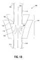
- FIG. 1( b )is an illustration of a cross-sectional view at line x-x of the apparatus shown in FIG. 1( a ) and including a fluid path and a coupling located in the fluid path and substantially aligned along the field lines of a force field in accordance with some embodiments.
- FIG. 1( c )is block diagram of an apparatus including the apparatus shown FIG. 1( a ) and coupled to a source of radioactive microparticles and a patient for use in connection with therapies, such as cancer therapies, in accordance with some embodiments.
- FIG. 1( d )is a flow diagram of a method including introducing a fluid including one or more microparticles into a fluid path including a coupling and substantially aligning the fluid path near the coupling with a force field.
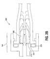
- FIG. 2( a )is an illustration of a cross-sectional view of an apparatus including the fluid path shown in FIG. 1( a ) , the coupling shown in FIG. 1( a ) and located in the fluid path shown in FIG. 1( a ) , and a nozzle located in the fluid path to move a fluid through a stagnant region located near the coupling in accordance with some embodiments.
- FIG. 2( b )is a detailed illustration of an apparatus including the coupling shown in FIG. 2( a ) , the nozzle, shown in FIG. 2( a ) , and a flat-face seal and an elastomeric seal in accordance with some embodiments.
- FIG. 3is an illustration of apparatus including a low flow rate fluid path including a coupling in accordance with some embodiments.
- FIG. 4is a flow diagram of a method including coupling a source of high density microparticles having high specific activity to a mammal, and delivering the high density microparticles having high specific activity to the mammal at a pressure of between about 5 psig and about 30 psig at the source in accordance with some embodiments.
- FIG. 5is a Summary Table showing catheter size, pressure ranges, equivalent flow rates, and flush volumes for microparticles suitable for use as the source of microparticles in accordance with some embodiments.
- FIG. 6is a flow diagram of a diagnostic method in accordance with some embodiments.
- FIG. 7is a flow diagram of a diagnostic method including analysis in accordance with some embodiments.
- FIG. 1( a )is a perspective view of an apparatus 100 to convey a fluid in accordance with some embodiments.
- the apparatus 100is suitable for use in connection with systems and devices that convey or deliver a fluid.
- a fluidis a continuous amorphous substance that is readily reshaped and has a tendency to assume the shape of its container.
- the apparatus 100is not limited to use in connection with a particular fluid or a particular application or industry. Exemplary fluids suitable for use in connection with the apparatus 100 include liquids and gases. Further embodiments of the apparatus 100 are shown in FIGS. 1( b ), 1( c ), 2( a ), and 2( b ) and described below.
- FIG. 1( b )is an illustration of a cross-sectional view at line x-x of the apparatus 100 , shown in FIG. 1( a ) , including a fluid path 102 and a coupling 104 located in the fluid path 102 and substantially aligned along the field lines of a force field 106 in accordance with some embodiments.
- the fluid path 102includes a proximal end 108 and a distal end 110 and provides a path or conduit to convey or deliver a fluid from the proximal end 108 to a distal end 110 .
- the delivery of a fluid intravenously for therapeutic use in the treatment of diseaseis one exemplary application of the apparatus 100 .
- the apparatus 100provides for the delivery of a fluid, such as a fluid including one or more radioactive microparticles, to a human vascular system for the treatment of cancer.
- a fluidsuch as a fluid including one or more radioactive microparticles
- Liver canceris an exemplary disease for which therapies have been developed that can benefit from the use of the apparatus 100 .
- Cancer and other disease statescan be diagnosed using microparticle injections.
- the microvascular bed of cancer lesions, or other diseases, and surrounding healthy tissuecan be characterized to allow treatment planning, including but not limited to the number of therapeutic microspheres and the specific activity of the therapeutic microspheres in a subsequent treatment. Other treatments can be planned from the knowledge of the microvascular bed.
- the fluid path 102is formed from a conduit, such as a tube or microtube.
- a tubeis a conduit that has an inside diameter greater than a few thousand microns.
- a microtubeis a tube that has an inside diameter a between about a fraction of a micron and a few thousand microns.
- the inside diameter of the conduitis not limited to a particular value.
- the fluid path 102is formed from a conduit of sufficient diameter to allow the microparticles to flow unimpeded from the proximal end 108 to the distal end 110 .
- the inside diameter of a conduit that forms the fluid path 102is between about twenty-five micrometers and about fifty micrometers.
- the conduitcan be flexible or inflexible.
- Exemplary materials suitable for use in connection with the fabrication of the conduit that forms the fluid path 102include polystyrene, plastic, and metals, such as stainless steel.
- the coupling 104 included in the fluid path 102provides a mechanical connection or link between two or more objects, such as two or more pieces of conduit 112 and 114 or between a conduit and a catheter.
- a couplingcan be formed separately from the objects to be connected or the coupling can be integrated with the objects.
- the coupling 104is not limited to a particular type of coupling. Various couplings, connectors, and fittings are suitable for use in forming the coupling 104 in the fluid path 102 of the apparatus 100 .
- a Luer connectoris one type of coupling used as an interconnection component in vascular fluid delivery systems.
- a Luer connectorincludes a tapered barrel and a conical male part that fits into the barrel without a seal. In some embodiments, the taper is about six percent.
- the apparatus 100includes a Luer connector for the coupling 104 in the fluid path 102 .
- the coupling materialis selected to be compatible with the fluid and the environment and operating conditions, such as temperature and pressure, of the fluid path 102 .
- the apparatus 100conveys a fluid, such as a fluid including one or more microparticles, along the fluid path 102 .
- a microparticlemay be spherical but it need not be spherical.
- Solid or hollow glass or glass composite beadscan form microparticles suitable for use in connection with the apparatus 100 .
- each of the one or more microparticleshas a specific gravity of more than about 1.5.
- microparticleincludes nanoparticles, microparticles, and microspheres.
- Nanoparticlesinclude particles and nanospheres having a diameter of about fifty nanometers to about 1000 nanometers.
- Microparticlesinclude particles having a diameter of between about 1 ⁇ m to about 1000 ⁇ m.
- Microspheresinclude substantially spherical elements having a diameter between about 1 ⁇ m and about 1000 ⁇ m.
- Exemplary materials suitable for use in forming microparticlesinclude inorganic, organic, polymer, radioactive and magnetic materials.
- Inorganic materialsinclude metals, silica, alumina, titania, glass, and ceramic.
- Organic materialsinclude polystyrene, melanine, and polylactide.
- Polymer materialsinclude polyurethane, lignin, polyamide, silicone, copolymers and trimers.
- a radioactive materialexhibits the spontaneous emission of a stream of particles or electromagnetic rays during nuclear decay.
- the streammay include atomic or subatomic particles that may be charged positively or negatively.
- Alpha particles and positronsare exemplary positively charged particles.
- Beta particlesare exemplary negatively charged particles.
- Radioactive materialsinclude radioactive oxides and radioactive polymers.
- a magnetic materialresponds to a magnetic field. Magnetic materials include some metals, such as iron, ferromagnetic, and paramagnetic materials. The surface of a microparticle is not limited to being formed from a particular material.
- the fluid path 102 near the coupling 104is substantially aligned with the force field 106 .
- the fluid path 102is substantially aligned with the force field 106 when the angle between the direction of travel of microparticles in the fluid path 102 and the direction of the force field 106 is between about thirty-five degrees and about forty-five degrees.
- the fluid path 102is very substantially aligned with the force field 106 when the angle between the direction of travel of microparticles in the fluid path 102 and the direction of the force field is less than about thirty-five degrees.
- the force field 106is not limited to a particular type of force field. Exemplary force fields suitable for use in connection with the apparatus 100 include gravitational force fields, magnetic force fields, centrifugal force fields, and electric force fields.
- the force field 106can be static or dynamic. A static force field does not vary with time. A dynamic force field varies with time.
- the substantial alignment of the fluid path 102 near the coupling 104 with the force field 106reduces the likelihood of the microparticles being trapped in a gap 116 created in mismatched fittings of the coupling 104 . Further, fewer microparticles enter a stagnant fluid region 118 at a re-entrant corner 120 , when the fluid path 102 is substantially aligned with the force field 106 . Finally, microparticles that enter the stagnant fluid region 118 travel in the direction of the force field 106 into a turbulent region 122 where they are re-entrained or pulled into the fluid flow of the fluid path 102 .
- FIG. 1( c )is block diagram of an apparatus 130 including the apparatus 100 , shown FIG. 1( b ) , coupled to a source of radioactive microparticles 132 and a patient 134 for use in connection with therapies, such as cancer therapies, in accordance with some embodiments.
- the source of radioactive microparticles 132includes a container, such as a vial, to hold a fluid including radioactive microparticles.
- the containeris either shielded or maintained in a shielded case to provide protection from the radiation emitted by the radioactive microparticles 132 .
- a catheter 136can provide a coupling from the fluid path 102 of the apparatus 100 to the patient 134 .
- the catheter 136is a hollow flexible tube for insertion into a body cavity, duct, or vessel to allow the passage of fluids.
- the apparatus 100is included in the catheter 136 .
- FIG. 1( d )is a flow diagram of a method 140 including introducing a fluid including one or more microparticles into a fluid path including a coupling (block 142 ), and substantially aligning the fluid path near the coupling with a force field (block 144 ).
- aligning the fluid path near the coupling with the force fieldincludes aligning the fluid path near the coupling with a gravitational field.
- the method 140further includes introducing a cancer patient into the fluid path.
- introducing the fluid including one or more microparticles into the fluid path including the couplingincludes introducing a slurry of radioactive microparticles under pressure into the fluid path.
- the methodfurther includes introducing a flushing fluid having a volume of between about twenty milliliters and about eighty milliliters into the fluid path at an operating pressure of about thirty pounds per square inch per square inch gauge.
- FIG. 2( a )is an illustration of a cross-sectional view of an apparatus 200 including the fluid path 102 , shown in FIG. 1( a ) , the coupling 104 , shown in FIG. 1( a ) , located in the fluid path 102 , and a nozzle 202 located in the fluid path 102 to move a fluid through a stagnant region 204 located near the coupling 104 .
- the nozzle 202includes an input port 206 and an output port 208 .
- the nozzle 202includes a side port 210 .
- the nozzle 202is not limited to a particular number of side ports.
- the nozzle 202includes the side port 210 and one or more additional side ports, such as side port 211 .
- the fluid path 102includes the proximal end 108 , shown in FIG. 1( b ) , and the distal end 110 , shown in FIG. 1( b ) , and provides a path or conduit to convey or deliver a fluid from the proximal end 108 to the distal end 110 .
- the delivery of a fluid intravenously for therapeutic use in the treatment of diseaseis one exemplary application of the apparatus 200 .
- the apparatus 200provides for the delivery of a fluid, such as a fluid including one or more radioactive microparticles, to a human vascular system for the treatment of cancer. Liver cancer is an exemplary disease for which therapies have been developed that can benefit from the use of the apparatus 200 .
- the stagnant region 204is an interior area of the coupling 104 in which microparticles entering the coupling 104 at the input port 206 of the nozzle 202 can become trapped. When microparticles become trapped in the stagnant region 204 they do not pass through the coupling 104 to the distal end 110 . In some systems, such as therapeutic systems, it is desirable to keep the number of trapped microparticles low.
- the input port 206 of the nozzle 202has an input port cross-sectional area and the output port 208 has an output port cross-sectional area. Making the cross-sectional area of the input port 206 greater than the cross-sectional area of the output port 208 reduces the likelihood that microparticles traveling along the fluid path 102 will become trapped in the stagnant region 204 .
- the output port 208has a diameter of between about 0.2 millimeters and about 1 millimeter. In some embodiments, the output port 208 cross-sectional area is about forty percent of the input port 206 cross-sectional area.
- the output port 208 diameteris equal to between about five microparticle and about ten microparticle diameters.
- making the cross-sectional area of the input port greater than the cross-sectional area of the output portforces fluid flow through the side port 210 to assist in moving microparticles through the stagnant region 204 .
- the velocity of the fluid at the output port 208 of the nozzle 202creates a low pressure region to draw fluid and microparticles from the stagnant region 204 into the fluid path 102 . Further, the nozzle 202 occupies a volume in the coupling 104 which increases the flow rate and entrainment of microparticles into the fluid path 102 near the nozzle 202 . In addition, positioning the output port 208 of the nozzle 202 beyond the stagnant region 204 results in delivery of substantially all microparticles in the fluid to a location in the coupling 104 beyond the stagnant region 204 .
- the nozzle 202includes a nozzle fluid path 212 located between the input port 206 and the output port 208 .
- the nozzle fluid path 212includes a taper 214 .
- the slope of the taper 214is less than about forty-five degrees.
- the slope of the taper 214is the largest slope of the curve of the nozzle fluid path 212 between the input port 206 and the output port 208 .
- the likelihood of microparticle bridging along the nozzle fluid path 212is reduced. Microparticle bridging occurs when a group of microparticles block or partially block the nozzle fluid path 212 .
- the nozzle 202includes the side port 210 .
- the side port 210is an opening located on a side surface of the nozzle 202 . Introduction of the side port 210 into the nozzle 202 changes the dynamics of the fluid flow in the coupling 104 .
- the side port 210provides a fluid path through the stagnant region 204 for a fluid entering the nozzle 202 at the input port 206 .
- the side port 210is located near the input port 206 of the nozzle 202 . Further, as described above, making the cross-sectional area of the input port 206 greater than the cross-sectional area of the output port 208 creates a back pressure to force more fluid flow through the side port 210 .
- the fluid flow at the side port 210induces turbulence near the nozzle 202 that sweeps microparticles from the stagnant region 204 near the nozzle 202 into the fluid path 102 .
- the fluid flow provided by the side port 210 to the stagnant region 204removes substantially all microparticles from the stagnant region 204 .
- the side port 210is not limited to a particular shape.
- the side port 210is substantially a cylindrical passage that has a diameter at least as large as the largest microparticle.
- the side port diametershould be at least two or more microparticle diameters. In some embodiments, the side port diameter is about 0.25 millimeters.
- the nozzle 202is not limited to a particular number of side ports.
- the side port 210can be replicated along the perimeter of the nozzle 202 .
- the replication of the side port 210is not limited to a particular configuration.
- the side port 210includes two or more side ports spaced a substantially equal distance from each other along the perimeter of the nozzle 202 .
- the side port 210includes four side ports with each of the four side ports spaced a substantially equal distance from each other along the perimeter of the nozzle 202 .
- the nozzle 202includes a nozzle flange 216 .
- the nozzle flange 216is sized and centered in the coupling 104 to form a seal at the leading edge of the nozzle flange 216 .
- the purpose of the seal between the nozzle flange 216 and the coupling 104is to substantially prevent formation of the gap 116 . Preventing formation of the gap 116 reduces the number of potential sites that can trap microparticles in the coupling 104 .
- a fluidenters the apparatus 200 at the proximal end 108 and flows along the fluid path 102 through the coupling 104 and the nozzle 202 and exits the coupling 104 at the distal end 110 .
- the coupling 104 and the nozzle 202provide a fluid flow that keeps the number of microparticles trapped in regions of the coupling 104 , such as the stagnant region 204 , low.
- FIG. 2( b )is a detailed illustration of an apparatus 220 including the coupling 104 , shown in FIG. 2( a ) , the nozzle 202 , shown in FIG. 2( a ) , and a flat-face seal 222 and an elastomeric seal 224 in accordance with some embodiments.
- the nozzle 202includes the nozzle flange 216 .
- the flat-face seal 222is formed between in the coupling 104 and the nozzle flange 216 .
- a flat-face sealincludes a surface-to-surface seal between the two components.
- the coupling 104includes the elastomeric seal 224 .
- the elastomeric seal 224is formed by a ring of elastomeric material compressed between the two components of the coupling 104 .
- the apparatus 200shown in FIG. 2( a ) and the apparatus 220 shown in FIG. 2( b ) can be included in a fluid delivery system coupled to a patient.
- each of the apparatus 200 and 220enables effective infusions of high density, high potency microparticles at low infusion pressure and flow rates.
- the low infusion pressurereduces the likelihood of leakage.
- the low flow ratereduces the possibility of reflux (back flow into a patient's vasculature) which in turn increases the likelihood that the microparticles will be delivered to the target.
- FIG. 3is an illustration of apparatus 300 including a low flow rate fluid path 302 including a coupling 304 in accordance with some embodiments.
- the coupling 304has a proximal end 306 and a distal end 308 .
- the low flow rate fluid path 302 including the coupling 304delivers at least about 90% of a source of high density microparticles from the proximal end 306 to the distal end 308 of the coupling 304 .
- a source of high density microparticlesincludes ten million particles
- the apparatus 300delivers at least about nine million high density microparticles from the source to the distal end 308 of the coupling 304 .
- a catheteris an exemplary coupling suitable for use in connection with the apparatus 300 .
- the low flow rate fluid path 302has a flow rate of between about 0.05 milliliters per second and about 0.93 milliliters per second.
- a high density microparticlehas a specific gravity of greater than about 1.5.
- a high specific activity radioactive microparticlehas a specific activity of greater than about 0.5 Ci/g.
- high specific activityrefers to the concentration of active ingredient, for example, a therapeutic drug or enhancing drug such as an oxidizing agent.
- the apparatus 300improves microparticle delivery to a target and is particularly useful when the volume in the coupling 304 available to trap microparticles exceeds about 5% of the volume of the microparticles intended for delivery to the target.
- FIG. 4is a flow diagram of a method 400 including coupling a source of high density microparticles having high specific activity to a mammal (block 402 ), and delivering the high density microparticles having high specific activity to the mammal at a pressure of between about 5 psig and about 30 psig at the source (block 404 ).
- coupling the source of high density microparticles having high specific activity to the mammalincludes connecting a catheter between the source and the mammal.
- delivering the high density microparticles having high specific activity to the mammal at the pressure of between about 5 psig and about 30 psig at the sourceincludes delivering more than about 90% of the high density microparticles available at the source to the mammal.
- FIG. 5is a Summary Table showing catheter size, pressure ranges, equivalent flow rates, and flush volumes for microparticles suitable for use as the source of microparticles in accordance with some embodiments.
- the pressure range in the fluid path 302shown in FIG. 4
- the equivalent flowis 0.49 ⁇ 0.44 mL/s and the flush volume is less than about 60 ml.
- the pressure range in the fluid path 302shown in FIG. 4
- the equivalent flowis 2.1 ⁇ 0.9 and the flush volume is less than about 60 ml.
- a source of high density microparticlescan include a seal rated for a lower pressure than for higher pressure fluid paths.
- FIG. 6is a flow diagram of a diagnostic method 600 in accordance with some embodiments.
- the method 600includes delivering one or more microparticles to a subject (block 602 ), and imaging the one or more microparticles to form image data (block 604 ).
- the image datacan be analyzed by a physician, clinician, or a computing system to generate a diagnosis.
- the image datais not limited to a particular type of data. Exemplary types of data include digital, such as digital data stored in a computing system, analog, such as photographs or other displayable images, and mixed digital and analog.
- delivering the one or more microparticles to the subjectincludes delivering the one or more microparticles to a microvascular bed.
- a microvascular bedincludes the small vascular structures in organs, such as the human liver. These small vascular structures can trap substantially spherical microparticles.
- delivering the one or more microparticles to the subjectincludes delivering one or more radioactive microparticles to the subject.
- delivering the one or more microparticles to the microvascular bedincludes delivering the one or more microparticles to the microvascular bed in a human liver or other human organ.
- delivering the one or more microparticles to the microvascular bedincludes delivering one or more radioactive microparticles to the microvascular bed in a human liver, breast, brain, or other human organ.
- the imaging of the microparticlesis not limited to a particular method. Any method of imaging capable of detecting microparticles or clusters of microparticles is suitable for use in connection with the method 600 . Exemplary imaging methods include ultrasound, magnetic resonance imaging, and computer aided tomography.
- FIG. 7is a flow diagram of a diagnostic method 700 including analysis in accordance with some embodiments.
- the method 700includes conveying one or more substantially spherical microparticles to a subject (block 702 ), imaging the one or more substantially spherical microparticles to form image data (block 704 ), and analyzing the image data to identify an anomalous condition (block 706 ). Cancer is one example of an anomalous condition that can be detected and analyzed using the method 700 .
- the method 700also includes delivering a small numbers of radiocative microparticles a subject, such as an animal, analyzing the location and distribution of the microparticles in the subject, and a generating a treatment regime from the analysis.
- the treatment regimecan include delivering a larger number of substantially spherical microparticles to the subject.
- conveying the one or more substantially spherical microparticles to a subjectincludes conveying one or more radioactive microparticles to the subject.
- analyzing the image data to identify the anomalous conditionincludes comparing the image data against data that identifies known diseases to identify a an animal disease state.
- imaging the one or more substantially spherical microparticles to form image dataincludes imaging using a magnetic resonance imaging system.
- the methods of imagingare not limited to a particular method. Any imaging method capable of detecting microparticles can be used in connection with the described diagnostic methods.
- Exemplary imaging systemsinclude systems that image using waves, such as electromagnetic or acoustic waves.
- Exemplary imaging systems that use electromagnetic wavesinclude magnetic resonance imaging and computer aided tomography.
- Exemplary imaging systems that use acoustic wavesinclude ultrasound imaging systems.
Landscapes
- Health & Medical Sciences (AREA)
- Engineering & Computer Science (AREA)
- General Health & Medical Sciences (AREA)
- Public Health (AREA)
- Anesthesiology (AREA)
- Biomedical Technology (AREA)
- Heart & Thoracic Surgery (AREA)
- Hematology (AREA)
- Life Sciences & Earth Sciences (AREA)
- Animal Behavior & Ethology (AREA)
- Veterinary Medicine (AREA)
- Vascular Medicine (AREA)
- Medical Informatics (AREA)
- Dermatology (AREA)
- Infusion, Injection, And Reservoir Apparatuses (AREA)
- Radiation-Therapy Devices (AREA)
- Media Introduction/Drainage Providing Device (AREA)
- Magnetic Resonance Imaging Apparatus (AREA)
- Medicines Containing Antibodies Or Antigens For Use As Internal Diagnostic Agents (AREA)
- Jet Pumps And Other Pumps (AREA)
Abstract
Description
Claims (10)
Priority Applications (14)
| Application Number | Priority Date | Filing Date | Title |
|---|---|---|---|
| US11/479,274US10369343B2 (en) | 2006-06-30 | 2006-06-30 | Apparatus and method to convey a fluid |
| JP2009517469AJP5561821B2 (en) | 2006-06-30 | 2007-06-28 | Apparatus and method for transferring fluid |
| CA2888052ACA2888052A1 (en) | 2006-06-30 | 2007-06-28 | Apparatus and method to convey a fluid |
| PCT/IB2007/001780WO2008004060A2 (en) | 2006-06-30 | 2007-06-28 | Apparatus and method to convey a fluid |
| CA2655918ACA2655918C (en) | 2006-06-30 | 2007-06-28 | Apparatus and method to convey a fluid |
| BRPI0713872ABRPI0713872A8 (en) | 2006-06-30 | 2007-06-28 | APPLIANCE AND METHOD FOR TRANSPORTING A FLUID |
| EP07804545AEP2035714A4 (en) | 2006-06-30 | 2007-06-28 | APPARATUS AND METHOD FOR DELIVERING A FLUID |
| RU2009103013/14ARU2446832C2 (en) | 2006-06-30 | 2007-06-28 | Method of fluid supply and device for implementation thereof |
| ZA2008/10860AZA200810860B (en) | 2006-06-30 | 2008-12-23 | Apparatus and method to convey a fluid |
| US12/767,510US20100210936A1 (en) | 2006-06-30 | 2010-04-26 | Apparatus and method to convey a fluid |
| US12/767,491US20100211045A1 (en) | 2006-06-30 | 2010-04-26 | Apparatus and method to convey a fluid |
| US13/542,346US10369344B2 (en) | 2006-06-30 | 2012-07-05 | Apparatus and method to convey a fluid |
| JP2012255119AJP5574507B2 (en) | 2006-06-30 | 2012-11-21 | Apparatus and method for transferring fluid |
| JP2013162465AJP5875080B2 (en) | 2006-06-30 | 2013-08-05 | Apparatus and method for transferring fluid |
Applications Claiming Priority (1)
| Application Number | Priority Date | Filing Date | Title |
|---|---|---|---|
| US11/479,274US10369343B2 (en) | 2006-06-30 | 2006-06-30 | Apparatus and method to convey a fluid |
Related Child Applications (3)
| Application Number | Title | Priority Date | Filing Date |
|---|---|---|---|
| US12/767,491DivisionUS20100211045A1 (en) | 2006-06-30 | 2010-04-26 | Apparatus and method to convey a fluid |
| US12/767,510DivisionUS20100210936A1 (en) | 2006-06-30 | 2010-04-26 | Apparatus and method to convey a fluid |
| US13/542,346ContinuationUS10369344B2 (en) | 2006-06-30 | 2012-07-05 | Apparatus and method to convey a fluid |
Publications (2)
| Publication Number | Publication Date |
|---|---|
| US20080004599A1 US20080004599A1 (en) | 2008-01-03 |
| US10369343B2true US10369343B2 (en) | 2019-08-06 |
Family
ID=38877628
Family Applications (4)
| Application Number | Title | Priority Date | Filing Date |
|---|---|---|---|
| US11/479,274Active2028-10-20US10369343B2 (en) | 2006-06-30 | 2006-06-30 | Apparatus and method to convey a fluid |
| US12/767,491AbandonedUS20100211045A1 (en) | 2006-06-30 | 2010-04-26 | Apparatus and method to convey a fluid |
| US12/767,510AbandonedUS20100210936A1 (en) | 2006-06-30 | 2010-04-26 | Apparatus and method to convey a fluid |
| US13/542,346ActiveUS10369344B2 (en) | 2006-06-30 | 2012-07-05 | Apparatus and method to convey a fluid |
Family Applications After (3)
| Application Number | Title | Priority Date | Filing Date |
|---|---|---|---|
| US12/767,491AbandonedUS20100211045A1 (en) | 2006-06-30 | 2010-04-26 | Apparatus and method to convey a fluid |
| US12/767,510AbandonedUS20100210936A1 (en) | 2006-06-30 | 2010-04-26 | Apparatus and method to convey a fluid |
| US13/542,346ActiveUS10369344B2 (en) | 2006-06-30 | 2012-07-05 | Apparatus and method to convey a fluid |
Country Status (8)
| Country | Link |
|---|---|
| US (4) | US10369343B2 (en) |
| EP (1) | EP2035714A4 (en) |
| JP (3) | JP5561821B2 (en) |
| BR (1) | BRPI0713872A8 (en) |
| CA (2) | CA2655918C (en) |
| RU (1) | RU2446832C2 (en) |
| WO (1) | WO2008004060A2 (en) |
| ZA (1) | ZA200810860B (en) |
Families Citing this family (3)
| Publication number | Priority date | Publication date | Assignee | Title |
|---|---|---|---|---|
| CA2750182A1 (en)* | 2008-12-30 | 2010-07-08 | Schlumberger Canada Limited | Submersible pump motor protector |
| CN106099090B (en)* | 2010-03-26 | 2019-02-15 | 株式会社半导体能源研究所 | The forming method of the electrode of secondary cell and secondary cell |
| EP3870263A4 (en) | 2018-10-23 | 2022-08-03 | ABK Biomedical Incorporated | DISPENSING DEVICE |
Citations (44)
| Publication number | Priority date | Publication date | Assignee | Title |
|---|---|---|---|---|
| JPS58156776A (en) | 1982-03-10 | 1983-09-17 | Babcock Hitachi Kk | Sealing device for duct |
| US4429856A (en)* | 1981-12-18 | 1984-02-07 | Mallinckrodt, Inc. | Inflation valve |
| US4674480A (en) | 1984-05-25 | 1987-06-23 | Lemelson Jerome H | Drug compositions and methods of applying same |
| JPH0454396A (en) | 1990-06-25 | 1992-02-21 | Konica Corp | Liquid connection structure |
| US5242393A (en)* | 1992-06-18 | 1993-09-07 | Becton, Dickinson And Company | Valved blunt cannula injection site |
| JPH06246668A (en) | 1993-02-19 | 1994-09-06 | Kanebo Ltd | Vacuum sucker device |
| JPH06246669A (en) | 1993-02-23 | 1994-09-06 | Hitachi Ltd | Workpiece transfer feeder for semiconductor device |
| US5660205A (en)* | 1994-12-15 | 1997-08-26 | Epstein; Alan B. | One-way valve |
| US5817069A (en)* | 1996-02-28 | 1998-10-06 | Vadus, Inc. | Valve assembly |
| WO1998056435A1 (en) | 1997-06-13 | 1998-12-17 | Micro Therapeutics, Inc. | Contoured syringe and novel luer hub and methods for embolizing blood vessels |
| JPH11182751A (en) | 1997-12-24 | 1999-07-06 | Flowell:Kk | Joint for tubing |
| RU2137502C1 (en) | 1994-02-23 | 1999-09-20 | Шеринг Аг | Gas-containing microparticles, microparticles- containing means, their utilization in ultrasonic diagnostics, and method for preparing these particles and means |
| EP1035884A1 (en) | 1997-12-01 | 2000-09-20 | SciMed Life Systems, Inc. | Catheter system of specified dead space for the delivery of a low volume liquid bolus |
| JP3118508B2 (en) | 1997-11-18 | 2000-12-18 | 株式会社エダキン | Connection structure of fixed frame and open / close frame in advertising display structure |
| US6165168A (en)* | 1997-09-02 | 2000-12-26 | Russo; Ronald D. | Closed system adapter for catheters |
| EP1069888A1 (en) | 1998-04-09 | 2001-01-24 | Nycomed Imaging As | Use of particulate contrast agents in diagnostic imaging for studying physiological parameters |
| JP2001330185A (en) | 2000-05-22 | 2001-11-30 | Kubota Corp | Seismic joints and pipelines |
| JP2001349483A (en) | 2000-06-07 | 2001-12-21 | New Delta Ind Co | Injection pipe-connecting structure of spreader |
| US6343603B1 (en)* | 1998-10-09 | 2002-02-05 | Fisher & Paykel Limited | Connector |
| US20020084290A1 (en)* | 2000-11-10 | 2002-07-04 | Therics, Inc. | Method and apparatus for dispensing small volume of liquid, such as with a weting-resistant nozzle |
| US20020197211A1 (en) | 1999-08-27 | 2002-12-26 | Ingrid Henriksen | Administration of dispersions by infusion |
| US20030013951A1 (en) | 2000-09-21 | 2003-01-16 | Dan Stefanescu | Database organization and searching |
| US20030135113A1 (en)* | 1997-03-13 | 2003-07-17 | Biocardia, Inc. | Method of drug delivery to interstitial regions of the myocardium |
| US20030221561A1 (en)* | 1999-12-06 | 2003-12-04 | Simcha Milo | Ultrasonic medical device |
| US20040002685A1 (en) | 2002-06-26 | 2004-01-01 | Medex, Inc. | Contrast dispensing system |
| US6709427B1 (en)* | 1999-08-05 | 2004-03-23 | Kensey Nash Corporation | Systems and methods for delivering agents into targeted tissue of a living being |
| US20040068157A1 (en) | 2002-10-04 | 2004-04-08 | Scimed Life Systems, Inc. | Method and apparatus for the delivery of brachytherapy |
| US20040096511A1 (en) | 2002-07-03 | 2004-05-20 | Jonathan Harburn | Magnetically guidable carriers and methods for the targeted magnetic delivery of substances in the body |
| US20040199141A1 (en) | 1998-08-11 | 2004-10-07 | Biocardia, Inc. | Catheter drug delivery system and method for use |
| US20040222144A1 (en) | 2001-01-30 | 2004-11-11 | Masaru Nakatani | Body fluid processor enabling direct hemoperfusion |
| US20040258614A1 (en) | 2003-06-20 | 2004-12-23 | University Of Maryland, Baltimore | Microparticles for microarterial imaging and radiotherapy |
| WO2005004973A1 (en) | 2003-07-09 | 2005-01-20 | Jms Co., Ltd. | Mixed injection port |
| US20050020869A1 (en) | 1998-07-30 | 2005-01-27 | Hainfeld James F. | Methods of enhancing radiation effects with metal nanoparticles |
| US20050019257A1 (en) | 2003-07-11 | 2005-01-27 | Chong-Oh Kim | Radioactive magnetic fluids for treatment or diagnosis of cancer, process for preparing them and use thereof |
| US20050087715A1 (en)* | 2001-08-10 | 2005-04-28 | Doyle Mark C. | Valved male luer connector having sequential valve timing |
| US20050234431A1 (en) | 2004-02-10 | 2005-10-20 | Williams Michael S | Intravascular delivery system for therapeutic agents |
| US20060089605A1 (en) | 2004-10-25 | 2006-04-27 | P. Rowan Smith, Jr. | Medical connector |
| US20060129112A1 (en) | 1998-05-29 | 2006-06-15 | Lynn Lawrence A | Luer receiver and method for fluid transfer |
| US20070032775A1 (en) | 2000-01-24 | 2007-02-08 | Bracco Diagnostics, Inc. | Tabletop drug dispensing vial access adapter |
| US20070083162A1 (en) | 2005-10-11 | 2007-04-12 | Span-America Medical Systems, Inc. | Valve for intravenous catheter |
| US20070156103A1 (en) | 2005-12-29 | 2007-07-05 | Etan Chatlynne | Pressurized fluid reservoir for an infusion system |
| US20070260197A1 (en) | 2006-04-05 | 2007-11-08 | Mick Felix W | Radio-nuclear material delivery system |
| US7344491B1 (en) | 2003-11-26 | 2008-03-18 | Nanobiomagnetics, Inc. | Method and apparatus for improving hearing |
| US20080208052A1 (en) | 2004-04-16 | 2008-08-28 | Lepivert Patrick | Systems and methods for improving image-guided tissue ablation |
Family Cites Families (5)
| Publication number | Priority date | Publication date | Assignee | Title |
|---|---|---|---|---|
| JPS58106321U (en)* | 1982-01-14 | 1983-07-20 | ツカサ工業株式会社 | Outside air suction device at bent part of powder and granular material transfer piping |
| JPS58106320U (en)* | 1982-01-14 | 1983-07-20 | ツカサ工業株式会社 | Outside air suction device at bent part of powder and granular material transfer piping |
| US5514801A (en)* | 1992-12-29 | 1996-05-07 | Monsanto Company | Cyclic sulfone containing retroviral protease inhibitors |
| JP2005032533A (en)* | 2003-07-11 | 2005-02-03 | Goto Denshi Kk | Forming device of varnish to electric wire, and forming method of varnish |
| JP3118508U (en)* | 2005-11-11 | 2006-01-26 | 興國機工株式会社 | Swivel joint structure |
- 2006
- 2006-06-30USUS11/479,274patent/US10369343B2/enactiveActive
- 2007
- 2007-06-28BRBRPI0713872Apatent/BRPI0713872A8/ennot_activeIP Right Cessation
- 2007-06-28CACA2655918Apatent/CA2655918C/ennot_activeExpired - Fee Related
- 2007-06-28RURU2009103013/14Apatent/RU2446832C2/ennot_activeIP Right Cessation
- 2007-06-28EPEP07804545Apatent/EP2035714A4/ennot_activeWithdrawn
- 2007-06-28JPJP2009517469Apatent/JP5561821B2/ennot_activeExpired - Fee Related
- 2007-06-28WOPCT/IB2007/001780patent/WO2008004060A2/enactiveApplication Filing
- 2007-06-28CACA2888052Apatent/CA2888052A1/ennot_activeAbandoned
- 2008
- 2008-12-23ZAZA2008/10860Apatent/ZA200810860B/enunknown
- 2010
- 2010-04-26USUS12/767,491patent/US20100211045A1/ennot_activeAbandoned
- 2010-04-26USUS12/767,510patent/US20100210936A1/ennot_activeAbandoned
- 2012
- 2012-07-05USUS13/542,346patent/US10369344B2/enactiveActive
- 2012-11-21JPJP2012255119Apatent/JP5574507B2/ennot_activeExpired - Fee Related
- 2013
- 2013-08-05JPJP2013162465Apatent/JP5875080B2/ennot_activeExpired - Fee Related
Patent Citations (48)
| Publication number | Priority date | Publication date | Assignee | Title |
|---|---|---|---|---|
| US4429856A (en)* | 1981-12-18 | 1984-02-07 | Mallinckrodt, Inc. | Inflation valve |
| JPS58156776A (en) | 1982-03-10 | 1983-09-17 | Babcock Hitachi Kk | Sealing device for duct |
| US4674480A (en) | 1984-05-25 | 1987-06-23 | Lemelson Jerome H | Drug compositions and methods of applying same |
| JPH0454396A (en) | 1990-06-25 | 1992-02-21 | Konica Corp | Liquid connection structure |
| US5242393A (en)* | 1992-06-18 | 1993-09-07 | Becton, Dickinson And Company | Valved blunt cannula injection site |
| JPH06246668A (en) | 1993-02-19 | 1994-09-06 | Kanebo Ltd | Vacuum sucker device |
| JPH06246669A (en) | 1993-02-23 | 1994-09-06 | Hitachi Ltd | Workpiece transfer feeder for semiconductor device |
| RU2137502C1 (en) | 1994-02-23 | 1999-09-20 | Шеринг Аг | Gas-containing microparticles, microparticles- containing means, their utilization in ultrasonic diagnostics, and method for preparing these particles and means |
| US6306366B1 (en) | 1994-02-23 | 2001-10-23 | Schering Aktiengesellschaft | Microparticles that contain gas, galactose and a saturated fatty acid |
| US5660205A (en)* | 1994-12-15 | 1997-08-26 | Epstein; Alan B. | One-way valve |
| US5817069A (en)* | 1996-02-28 | 1998-10-06 | Vadus, Inc. | Valve assembly |
| US20030135113A1 (en)* | 1997-03-13 | 2003-07-17 | Biocardia, Inc. | Method of drug delivery to interstitial regions of the myocardium |
| WO1998056435A1 (en) | 1997-06-13 | 1998-12-17 | Micro Therapeutics, Inc. | Contoured syringe and novel luer hub and methods for embolizing blood vessels |
| JP2002503991A (en) | 1997-06-13 | 2002-02-05 | マイクロ・テラピューティクス・インコーポレーテッド | Syringe and luer hub having novel shape and method of forming embolus |
| US6165168A (en)* | 1997-09-02 | 2000-12-26 | Russo; Ronald D. | Closed system adapter for catheters |
| JP3118508B2 (en) | 1997-11-18 | 2000-12-18 | 株式会社エダキン | Connection structure of fixed frame and open / close frame in advertising display structure |
| EP1035884A1 (en) | 1997-12-01 | 2000-09-20 | SciMed Life Systems, Inc. | Catheter system of specified dead space for the delivery of a low volume liquid bolus |
| JPH11182751A (en) | 1997-12-24 | 1999-07-06 | Flowell:Kk | Joint for tubing |
| RU2207808C2 (en) | 1998-04-09 | 2003-07-10 | Амершем Хелт АС | Method for applying contrasting agents in particle form in diagnostic visualization of for studying physiological parameters |
| EP1069888A1 (en) | 1998-04-09 | 2001-01-24 | Nycomed Imaging As | Use of particulate contrast agents in diagnostic imaging for studying physiological parameters |
| US20060129112A1 (en) | 1998-05-29 | 2006-06-15 | Lynn Lawrence A | Luer receiver and method for fluid transfer |
| US20050020869A1 (en) | 1998-07-30 | 2005-01-27 | Hainfeld James F. | Methods of enhancing radiation effects with metal nanoparticles |
| US20040199141A1 (en) | 1998-08-11 | 2004-10-07 | Biocardia, Inc. | Catheter drug delivery system and method for use |
| US6343603B1 (en)* | 1998-10-09 | 2002-02-05 | Fisher & Paykel Limited | Connector |
| US6709427B1 (en)* | 1999-08-05 | 2004-03-23 | Kensey Nash Corporation | Systems and methods for delivering agents into targeted tissue of a living being |
| US20020197211A1 (en) | 1999-08-27 | 2002-12-26 | Ingrid Henriksen | Administration of dispersions by infusion |
| US20030221561A1 (en)* | 1999-12-06 | 2003-12-04 | Simcha Milo | Ultrasonic medical device |
| US20070032775A1 (en) | 2000-01-24 | 2007-02-08 | Bracco Diagnostics, Inc. | Tabletop drug dispensing vial access adapter |
| JP2001330185A (en) | 2000-05-22 | 2001-11-30 | Kubota Corp | Seismic joints and pipelines |
| JP2001349483A (en) | 2000-06-07 | 2001-12-21 | New Delta Ind Co | Injection pipe-connecting structure of spreader |
| US20030013951A1 (en) | 2000-09-21 | 2003-01-16 | Dan Stefanescu | Database organization and searching |
| US20020084290A1 (en)* | 2000-11-10 | 2002-07-04 | Therics, Inc. | Method and apparatus for dispensing small volume of liquid, such as with a weting-resistant nozzle |
| US20040222144A1 (en) | 2001-01-30 | 2004-11-11 | Masaru Nakatani | Body fluid processor enabling direct hemoperfusion |
| US20050087715A1 (en)* | 2001-08-10 | 2005-04-28 | Doyle Mark C. | Valved male luer connector having sequential valve timing |
| US20040002685A1 (en) | 2002-06-26 | 2004-01-01 | Medex, Inc. | Contrast dispensing system |
| US20040096511A1 (en) | 2002-07-03 | 2004-05-20 | Jonathan Harburn | Magnetically guidable carriers and methods for the targeted magnetic delivery of substances in the body |
| US20040068157A1 (en) | 2002-10-04 | 2004-04-08 | Scimed Life Systems, Inc. | Method and apparatus for the delivery of brachytherapy |
| US20040258614A1 (en) | 2003-06-20 | 2004-12-23 | University Of Maryland, Baltimore | Microparticles for microarterial imaging and radiotherapy |
| WO2005004973A1 (en) | 2003-07-09 | 2005-01-20 | Jms Co., Ltd. | Mixed injection port |
| US20060184140A1 (en) | 2003-07-09 | 2006-08-17 | Jms Co, Ltd | Mixture injection port |
| US20050019257A1 (en) | 2003-07-11 | 2005-01-27 | Chong-Oh Kim | Radioactive magnetic fluids for treatment or diagnosis of cancer, process for preparing them and use thereof |
| US7344491B1 (en) | 2003-11-26 | 2008-03-18 | Nanobiomagnetics, Inc. | Method and apparatus for improving hearing |
| US20050234431A1 (en) | 2004-02-10 | 2005-10-20 | Williams Michael S | Intravascular delivery system for therapeutic agents |
| US20080208052A1 (en) | 2004-04-16 | 2008-08-28 | Lepivert Patrick | Systems and methods for improving image-guided tissue ablation |
| US20060089605A1 (en) | 2004-10-25 | 2006-04-27 | P. Rowan Smith, Jr. | Medical connector |
| US20070083162A1 (en) | 2005-10-11 | 2007-04-12 | Span-America Medical Systems, Inc. | Valve for intravenous catheter |
| US20070156103A1 (en) | 2005-12-29 | 2007-07-05 | Etan Chatlynne | Pressurized fluid reservoir for an infusion system |
| US20070260197A1 (en) | 2006-04-05 | 2007-11-08 | Mick Felix W | Radio-nuclear material delivery system |
Non-Patent Citations (6)
| Title |
|---|
| English language abstract of JP 2002-503991A, Feb. 5, 2002. |
| Japanese Office Action for Japanese Patent Application No. 2009-517469, with English translation, 13 pages, dated May 21, 2012. |
| Japanese Office Action for Japanese Patent Application No. 2012-255119, with English translation, 5 pages, dated Oct. 29, 2013. |
| Japanese Office Action with English translation for corresponding Japanese App. No. 2009-517469, 13 pages, dated Apr. 5, 2013. |
| PCT International Search Report; International App. No. PCT/IB2007/001780; dated Mar. 6, 2008. |
| Translation of an Office Action issued by the Russian Patent Office, dated Apr. 12, 2011, 7 pages. |
Also Published As
| Publication number | Publication date |
|---|---|
| JP5574507B2 (en) | 2014-08-20 |
| JP2013039429A (en) | 2013-02-28 |
| CA2888052A1 (en) | 2008-01-10 |
| CA2655918A1 (en) | 2008-01-10 |
| US20120283559A1 (en) | 2012-11-08 |
| RU2009103013A (en) | 2010-08-10 |
| WO2008004060A2 (en) | 2008-01-10 |
| WO2008004060A3 (en) | 2008-06-12 |
| JP5875080B2 (en) | 2016-03-02 |
| EP2035714A2 (en) | 2009-03-18 |
| US20100211045A1 (en) | 2010-08-19 |
| CA2655918C (en) | 2015-08-11 |
| EP2035714A4 (en) | 2012-12-19 |
| JP5561821B2 (en) | 2014-07-30 |
| US20080004599A1 (en) | 2008-01-03 |
| US20100210936A1 (en) | 2010-08-19 |
| BRPI0713872A2 (en) | 2012-12-18 |
| JP2013226459A (en) | 2013-11-07 |
| RU2446832C2 (en) | 2012-04-10 |
| US10369344B2 (en) | 2019-08-06 |
| BRPI0713872A8 (en) | 2016-12-06 |
| JP2009542278A (en) | 2009-12-03 |
| ZA200810860B (en) | 2010-02-24 |
Similar Documents
| Publication | Publication Date | Title |
|---|---|---|
| US8038182B2 (en) | Breakage resistant fitting | |
| Wilson et al. | Hepatocellular carcinoma: regional therapy with a magnetic targeted carrier bound to doxorubicin in a dual MR imaging/conventional angiography suite—initial experience with four patients | |
| Slack et al. | Acute hemodynamic effects and blood pool kinetics of polystyrene microspheres following intravenous administration | |
| Chen et al. | Poly (lactide-co-glycolide) microspheres for MRI-monitored transcatheter delivery of sorafenib to liver tumors | |
| Sheu et al. | MRI-monitored transcatheter intra-arterial delivery of SPIO-labeled natural killer cells to hepatocellular carcinoma: preclinical studies in a rodent model | |
| US20080167621A1 (en) | Multi-Barrel Syringe Having Integral Manifold | |
| US10369344B2 (en) | Apparatus and method to convey a fluid | |
| JP2010538762A (en) | Infusion and transfer systems for use with radioactive materials | |
| Rübenthaler et al. | Contrast-enhanced ultrasound in the follow-up of endoleaks after endovascular aortic repair (EVAR) | |
| Lu | FDG and 82Rb PET/MRI features of brain metastasis of breast cancer | |
| Snoeijink et al. | In vitro investigation of microcatheter behavior during microsphere injection in transarterial radioembolization | |
| JP2009542278A5 (en) | ||
| Jung et al. | Contrast-enhanced µCT for visualizing and evaluating murine intestinal inflammation | |
| Rietveld et al. | Drug release from docetaxel-entrapped core-crosslinked polymeric micelles: A population pharmacokinetic modelling approach based on clinical data | |
| Vlogman et al. | Impact of injection velocity on catheter-based drug delivery in bifurcating vessels: In silico and in vitro analysis | |
| Gotti | Microsphere angiography of the liver | |
| Sundset et al. | ¹⁷⁷Lu-PSMA radioligand therapy for metastatic castration-resistant prostate cancer | |
| Jiménez Sánchez | Targeted drug delivery for liver cancer: a patient-specific computational model of the particle transport during radio-embolisation | |
| CN201791189U (en) | Disposable particle intercepter for intravenous injection | |
| Ne’mati et al. | Numerical Analysis of Magnetic Nanoparticles Penetration within the Cancerous Tumor Tissue under Influence of External Magnet | |
| Prim et al. | Implications of Ultrasonographic Measurements of Internal Jugular Veins in the Placement of Central Venous Catheters in ENT Cancer Patients | |
| 勝山壮 et al. | Tissue distribution of particulates administered intravenously |
Legal Events
| Date | Code | Title | Description |
|---|---|---|---|
| AS | Assignment | Owner name:MDS (CANADA) INC., CANADA Free format text:ASSIGNMENT OF ASSIGNORS INTEREST;ASSIGNORS:SIMPSON, THOMAS J.;HAGERMAN, JIM;REEL/FRAME:018076/0580 Effective date:20060630 | |
| AS | Assignment | Owner name:NORDION (CANADA) INC., CANADA Free format text:CHANGE OF NAME;ASSIGNOR:MDS (CANADA) INC.;REEL/FRAME:028459/0159 Effective date:20101101 | |
| AS | Assignment | Owner name:8312176 CANADA INC., CANADA Free format text:ASSIGNMENT OF ASSIGNORS INTEREST;ASSIGNOR:NORDION (CANADA) INC.;REEL/FRAME:031975/0172 Effective date:20130712 | |
| AS | Assignment | Owner name:BTG INTERNATIONAL CANADA INC., CANADA Free format text:CHANGE OF NAME;ASSIGNOR:8312176 CANADA INC.;REEL/FRAME:034195/0158 Effective date:20130715 | |
| AS | Assignment | Owner name:BIOCOMPATIBLES UK LIMITED, ENGLAND Free format text:ASSIGNMENT OF ASSIGNORS INTEREST;ASSIGNOR:BTG INTERNATIONAL CANADA INC;REEL/FRAME:036151/0342 Effective date:20150713 | |
| STPP | Information on status: patent application and granting procedure in general | Free format text:NOTICE OF ALLOWANCE MAILED -- APPLICATION RECEIVED IN OFFICE OF PUBLICATIONS | |
| STPP | Information on status: patent application and granting procedure in general | Free format text:PUBLICATIONS -- ISSUE FEE PAYMENT VERIFIED | |
| STCF | Information on status: patent grant | Free format text:PATENTED CASE | |
| MAFP | Maintenance fee payment | Free format text:PAYMENT OF MAINTENANCE FEE, 4TH YEAR, LARGE ENTITY (ORIGINAL EVENT CODE: M1551); ENTITY STATUS OF PATENT OWNER: LARGE ENTITY Year of fee payment:4 | |
| AS | Assignment | Owner name:BOSTON SCIENTIFIC MEDICAL DEVICE LIMITED, IRELAND Free format text:ASSIGNMENT OF ASSIGNORS INTEREST;ASSIGNOR:BIOCOMPATIBLES UK LIMITED;REEL/FRAME:065533/0152 Effective date:20221215 |