US10368669B2 - System and method for stabilizing unintentional muscle movements - Google Patents
System and method for stabilizing unintentional muscle movementsDownload PDFInfo
- Publication number
- US10368669B2 US10368669B2US13/250,000US201113250000AUS10368669B2US 10368669 B2US10368669 B2US 10368669B2US 201113250000 AUS201113250000 AUS 201113250000AUS 10368669 B2US10368669 B2US 10368669B2
- Authority
- US
- United States
- Prior art keywords
- motion
- relative
- housing
- attachment arm
- user
- Prior art date
- Legal status (The legal status is an assumption and is not a legal conclusion. Google has not performed a legal analysis and makes no representation as to the accuracy of the status listed.)
- Active, expires
Links
- 230000033001locomotionEffects0.000titleclaimsabstractdescription81
- 238000000034methodMethods0.000titleclaimsabstractdescription30
- 230000000087stabilizing effectEffects0.000titleclaimsabstractdescription14
- 210000003205muscleAnatomy0.000titleabstractdescription30
- 230000007246mechanismEffects0.000claimsdescription36
- 206010044565TremorDiseases0.000claimsdescription19
- 230000001419dependent effectEffects0.000claimsdescription3
- 238000004519manufacturing processMethods0.000claimsdescription3
- 230000003370grooming effectEffects0.000claimsdescription2
- 238000005259measurementMethods0.000claims4
- 230000004044responseEffects0.000abstractdescription7
- 230000002411adverseEffects0.000abstractdescription6
- 230000008878couplingEffects0.000abstractdescription5
- 238000010168coupling processMethods0.000abstractdescription5
- 238000005859coupling reactionMethods0.000abstractdescription5
- 229910001285shape-memory alloyInorganic materials0.000description12
- 230000001133accelerationEffects0.000description10
- 230000000694effectsEffects0.000description7
- 230000006870functionEffects0.000description7
- 208000037265diseases, disorders, signs and symptomsDiseases0.000description6
- 208000035475disorderDiseases0.000description5
- 230000000926neurological effectEffects0.000description5
- 230000003044adaptive effectEffects0.000description4
- 201000006517essential tremorDiseases0.000description4
- 230000008859changeEffects0.000description3
- 238000010586diagramMethods0.000description3
- 230000007935neutral effectEffects0.000description3
- 238000005457optimizationMethods0.000description3
- 238000012546transferMethods0.000description3
- 238000011282treatmentMethods0.000description3
- 230000005355Hall effectEffects0.000description2
- 206010029216NervousnessDiseases0.000description2
- 208000018737Parkinson diseaseDiseases0.000description2
- 238000004458analytical methodMethods0.000description2
- 238000006073displacement reactionMethods0.000description2
- 238000001914filtrationMethods0.000description2
- 230000036541healthEffects0.000description2
- 238000012986modificationMethods0.000description2
- 230000004048modificationEffects0.000description2
- 230000006641stabilisationEffects0.000description2
- 238000011105stabilizationMethods0.000description2
- 230000009466transformationEffects0.000description2
- 208000019901Anxiety diseaseDiseases0.000description1
- 206010061818Disease progressionDiseases0.000description1
- 229910045601alloyInorganic materials0.000description1
- 239000000956alloySubstances0.000description1
- 230000036506anxietyEffects0.000description1
- 238000013459approachMethods0.000description1
- 230000008901benefitEffects0.000description1
- 210000004556brainAnatomy0.000description1
- 238000012512characterization methodMethods0.000description1
- 238000005094computer simulationMethods0.000description1
- 125000004122cyclic groupChemical group0.000description1
- 230000003247decreasing effectEffects0.000description1
- 238000013461designMethods0.000description1
- 238000001514detection methodMethods0.000description1
- 238000011161developmentMethods0.000description1
- 201000010099diseaseDiseases0.000description1
- 230000005750disease progressionEffects0.000description1
- 230000035622drinkingEffects0.000description1
- 238000005516engineering processMethods0.000description1
- 230000007613environmental effectEffects0.000description1
- 230000005484gravityEffects0.000description1
- 230000007774longtermEffects0.000description1
- 239000000463materialSubstances0.000description1
- 230000003278mimic effectEffects0.000description1
- 238000011458pharmacological treatmentMethods0.000description1
- 230000008569processEffects0.000description1
- 230000009467reductionEffects0.000description1
- 230000035945sensitivityEffects0.000description1
- 238000004088simulationMethods0.000description1
- 230000000638stimulationEffects0.000description1
- 230000001629suppressionEffects0.000description1
- 238000001356surgical procedureMethods0.000description1
- 230000000542thalamic effectEffects0.000description1
- 230000000930thermomechanical effectEffects0.000description1
Images


Classifications
- A—HUMAN NECESSITIES
- A47—FURNITURE; DOMESTIC ARTICLES OR APPLIANCES; COFFEE MILLS; SPICE MILLS; SUCTION CLEANERS IN GENERAL
- A47G—HOUSEHOLD OR TABLE EQUIPMENT
- A47G21/00—Table-ware
- A47G21/02—Forks; Forks with ejectors; Combined forks and spoons; Salad servers
- A—HUMAN NECESSITIES
- A47—FURNITURE; DOMESTIC ARTICLES OR APPLIANCES; COFFEE MILLS; SPICE MILLS; SUCTION CLEANERS IN GENERAL
- A47G—HOUSEHOLD OR TABLE EQUIPMENT
- A47G21/00—Table-ware
- A47G21/04—Spoons; Pastry servers
- A—HUMAN NECESSITIES
- A47—FURNITURE; DOMESTIC ARTICLES OR APPLIANCES; COFFEE MILLS; SPICE MILLS; SUCTION CLEANERS IN GENERAL
- A47G—HOUSEHOLD OR TABLE EQUIPMENT
- A47G21/00—Table-ware
- A47G21/08—Serving devices for one-handed persons
- A—HUMAN NECESSITIES
- A61—MEDICAL OR VETERINARY SCIENCE; HYGIENE
- A61B—DIAGNOSIS; SURGERY; IDENTIFICATION
- A61B5/00—Measuring for diagnostic purposes; Identification of persons
- A61B5/0002—Remote monitoring of patients using telemetry, e.g. transmission of vital signals via a communication network
- A61B5/0015—Remote monitoring of patients using telemetry, e.g. transmission of vital signals via a communication network characterised by features of the telemetry system
- A61B5/0022—Monitoring a patient using a global network, e.g. telephone networks, internet
- A—HUMAN NECESSITIES
- A61—MEDICAL OR VETERINARY SCIENCE; HYGIENE
- A61B—DIAGNOSIS; SURGERY; IDENTIFICATION
- A61B5/00—Measuring for diagnostic purposes; Identification of persons
- A61B5/103—Measuring devices for testing the shape, pattern, colour, size or movement of the body or parts thereof, for diagnostic purposes
- A61B5/11—Measuring movement of the entire body or parts thereof, e.g. head or hand tremor or mobility of a limb
- A61B5/1101—Detecting tremor
- A—HUMAN NECESSITIES
- A61—MEDICAL OR VETERINARY SCIENCE; HYGIENE
- A61B—DIAGNOSIS; SURGERY; IDENTIFICATION
- A61B5/00—Measuring for diagnostic purposes; Identification of persons
- A61B5/68—Arrangements of detecting, measuring or recording means, e.g. sensors, in relation to patient
- A61B5/6887—Arrangements of detecting, measuring or recording means, e.g. sensors, in relation to patient mounted on external non-worn devices, e.g. non-medical devices
- A—HUMAN NECESSITIES
- A61—MEDICAL OR VETERINARY SCIENCE; HYGIENE
- A61F—FILTERS IMPLANTABLE INTO BLOOD VESSELS; PROSTHESES; DEVICES PROVIDING PATENCY TO, OR PREVENTING COLLAPSING OF, TUBULAR STRUCTURES OF THE BODY, e.g. STENTS; ORTHOPAEDIC, NURSING OR CONTRACEPTIVE DEVICES; FOMENTATION; TREATMENT OR PROTECTION OF EYES OR EARS; BANDAGES, DRESSINGS OR ABSORBENT PADS; FIRST-AID KITS
- A61F2/00—Filters implantable into blood vessels; Prostheses, i.e. artificial substitutes or replacements for parts of the body; Appliances for connecting them with the body; Devices providing patency to, or preventing collapsing of, tubular structures of the body, e.g. stents
- A61F2/02—Prostheses implantable into the body
- A61F2/08—Muscles; Tendons; Ligaments
- A—HUMAN NECESSITIES
- A61—MEDICAL OR VETERINARY SCIENCE; HYGIENE
- A61F—FILTERS IMPLANTABLE INTO BLOOD VESSELS; PROSTHESES; DEVICES PROVIDING PATENCY TO, OR PREVENTING COLLAPSING OF, TUBULAR STRUCTURES OF THE BODY, e.g. STENTS; ORTHOPAEDIC, NURSING OR CONTRACEPTIVE DEVICES; FOMENTATION; TREATMENT OR PROTECTION OF EYES OR EARS; BANDAGES, DRESSINGS OR ABSORBENT PADS; FIRST-AID KITS
- A61F4/00—Methods or devices enabling patients or disabled persons to operate an apparatus or a device not forming part of the body
- G06F19/00—
- G—PHYSICS
- G16—INFORMATION AND COMMUNICATION TECHNOLOGY [ICT] SPECIALLY ADAPTED FOR SPECIFIC APPLICATION FIELDS
- G16H—HEALTHCARE INFORMATICS, i.e. INFORMATION AND COMMUNICATION TECHNOLOGY [ICT] SPECIALLY ADAPTED FOR THE HANDLING OR PROCESSING OF MEDICAL OR HEALTHCARE DATA
- G16H40/00—ICT specially adapted for the management or administration of healthcare resources or facilities; ICT specially adapted for the management or operation of medical equipment or devices
- G16H40/60—ICT specially adapted for the management or administration of healthcare resources or facilities; ICT specially adapted for the management or operation of medical equipment or devices for the operation of medical equipment or devices
- G16H40/67—ICT specially adapted for the management or administration of healthcare resources or facilities; ICT specially adapted for the management or operation of medical equipment or devices for the operation of medical equipment or devices for remote operation
- G—PHYSICS
- G16—INFORMATION AND COMMUNICATION TECHNOLOGY [ICT] SPECIALLY ADAPTED FOR SPECIFIC APPLICATION FIELDS
- G16Z—INFORMATION AND COMMUNICATION TECHNOLOGY [ICT] SPECIALLY ADAPTED FOR SPECIFIC APPLICATION FIELDS, NOT OTHERWISE PROVIDED FOR
- G16Z99/00—Subject matter not provided for in other main groups of this subclass
- A—HUMAN NECESSITIES
- A47—FURNITURE; DOMESTIC ARTICLES OR APPLIANCES; COFFEE MILLS; SPICE MILLS; SUCTION CLEANERS IN GENERAL
- A47G—HOUSEHOLD OR TABLE EQUIPMENT
- A47G2200/00—Details not otherwise provided for in A47G
- A47G2200/04—For person with a handicap
- A47G2200/046—For person with a handicap of holding or grasping
- A—HUMAN NECESSITIES
- A47—FURNITURE; DOMESTIC ARTICLES OR APPLIANCES; COFFEE MILLS; SPICE MILLS; SUCTION CLEANERS IN GENERAL
- A47J—KITCHEN EQUIPMENT; COFFEE MILLS; SPICE MILLS; APPARATUS FOR MAKING BEVERAGES
- A47J43/00—Implements for preparing or holding food, not provided for in other groups of this subclass
- A47J43/28—Other culinary hand implements, e.g. spatulas, pincers, forks or like food holders, ladles, skimming ladles, cooking spoons; Spoon-holders attached to cooking pots
- A—HUMAN NECESSITIES
- A61—MEDICAL OR VETERINARY SCIENCE; HYGIENE
- A61B—DIAGNOSIS; SURGERY; IDENTIFICATION
- A61B2562/00—Details of sensors; Constructional details of sensor housings or probes; Accessories for sensors
- A61B2562/02—Details of sensors specially adapted for in-vivo measurements
- A61B2562/0219—Inertial sensors, e.g. accelerometers, gyroscopes, tilt switches
- A—HUMAN NECESSITIES
- A61—MEDICAL OR VETERINARY SCIENCE; HYGIENE
- A61B—DIAGNOSIS; SURGERY; IDENTIFICATION
- A61B5/00—Measuring for diagnostic purposes; Identification of persons
- A61B5/40—Detecting, measuring or recording for evaluating the nervous system
- A61B5/4076—Diagnosing or monitoring particular conditions of the nervous system
- A61B5/4082—Diagnosing or monitoring movement diseases, e.g. Parkinson, Huntington or Tourette
- A—HUMAN NECESSITIES
- A61—MEDICAL OR VETERINARY SCIENCE; HYGIENE
- A61H—PHYSICAL THERAPY APPARATUS, e.g. DEVICES FOR LOCATING OR STIMULATING REFLEX POINTS IN THE BODY; ARTIFICIAL RESPIRATION; MASSAGE; BATHING DEVICES FOR SPECIAL THERAPEUTIC OR HYGIENIC PURPOSES OR SPECIFIC PARTS OF THE BODY
- A61H1/00—Apparatus for passive exercising; Vibrating apparatus; Chiropractic devices, e.g. body impacting devices, external devices for briefly extending or aligning unbroken bones
- A—HUMAN NECESSITIES
- A61—MEDICAL OR VETERINARY SCIENCE; HYGIENE
- A61H—PHYSICAL THERAPY APPARATUS, e.g. DEVICES FOR LOCATING OR STIMULATING REFLEX POINTS IN THE BODY; ARTIFICIAL RESPIRATION; MASSAGE; BATHING DEVICES FOR SPECIAL THERAPEUTIC OR HYGIENIC PURPOSES OR SPECIFIC PARTS OF THE BODY
- A61H23/00—Percussion or vibration massage, e.g. using supersonic vibration; Suction-vibration massage; Massage with moving diaphragms
- F—MECHANICAL ENGINEERING; LIGHTING; HEATING; WEAPONS; BLASTING
- F16—ENGINEERING ELEMENTS AND UNITS; GENERAL MEASURES FOR PRODUCING AND MAINTAINING EFFECTIVE FUNCTIONING OF MACHINES OR INSTALLATIONS; THERMAL INSULATION IN GENERAL
- F16F—SPRINGS; SHOCK-ABSORBERS; MEANS FOR DAMPING VIBRATION
- F16F7/00—Vibration-dampers; Shock-absorbers
- F16F7/10—Vibration-dampers; Shock-absorbers using inertia effect
- F16F7/1005—Vibration-dampers; Shock-absorbers using inertia effect characterised by active control of the mass
- G—PHYSICS
- G05—CONTROLLING; REGULATING
- G05B—CONTROL OR REGULATING SYSTEMS IN GENERAL; FUNCTIONAL ELEMENTS OF SUCH SYSTEMS; MONITORING OR TESTING ARRANGEMENTS FOR SUCH SYSTEMS OR ELEMENTS
- G05B13/00—Adaptive control systems, i.e. systems automatically adjusting themselves to have a performance which is optimum according to some preassigned criterion
- G05B13/02—Adaptive control systems, i.e. systems automatically adjusting themselves to have a performance which is optimum according to some preassigned criterion electric
- G05B13/0205—Adaptive control systems, i.e. systems automatically adjusting themselves to have a performance which is optimum according to some preassigned criterion electric not using a model or a simulator of the controlled system
- G05B13/021—Adaptive control systems, i.e. systems automatically adjusting themselves to have a performance which is optimum according to some preassigned criterion electric not using a model or a simulator of the controlled system in which a variable is automatically adjusted to optimise the performance
Definitions
- the present inventionrelates generally to unintentional muscle movements of a body, and more particularly, to a system and method for stabilizing the effects of these unintentional muscle movements.
- Unintentional muscle movements of the human body, or human tremorscan occur in individuals suffering from neurological motion disorders including but not limited to Parkinson's Disease (PD) and Essential Tremor (ET).
- ETis the most common neurological motion disorder affecting as many as 10 million individuals in the United States and 270 million individuals worldwide. Due to the debilitating muscle movements associated with this disease, individuals with ET have difficulty in performing many daily functions such as eating and drinking. As a result, these individuals often suffer from social isolation, depression/anxiety, and an overall reduced Health Related Quality of Life (HRQoL).
- HRQoLHealth Related Quality of Life
- Unintentional muscle movements of the human bodycan also occur in healthy individuals. These unintentional muscle movements are often exacerbated by environmental factors and situations that lead to fatigue, stress, nervousness, etc. For example, a military serviceperson may experience unintentional muscle movements while performing a surgical operation on the battlefield due to stress and nervousness and this may result in decreased performance.
- Surgical proceduressuch as Thalamotomy and thalamic Deep Brain Stimulation (DBS) can be expensive, dangerous, and limited in availability.
- Non-invasive solutionssuch as physically grounded tremor suppression devices, physically force a person's tremor to cease but require complex and costly structures, cause user discomfort and cannot differentiate between intended and unintended movements.
- the systemcomprises a housing.
- the housingincludes a subsystem.
- the systemalso includes an attachment arm coupled to the housing.
- At least one first sensoris placed along the attachment arm, wherein the attachment arm is configured to receive the object thereto.
- the subsystemstabilizes the position of the object.
- the methodcomprises providing a subsystem within a housing and coupling an attachment arm to the housing.
- the methodalso includes placing at least one first sensor along the attachment arm, wherein the attachment arm is configured to receive the object thereto.
- the subsystemstabilizes the position of the object.
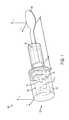
- FIG. 1illustrates a conventional handheld system that detects and compensates for unintentional muscle movements.
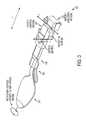
- FIG. 2illustrates a system that detects and compensates for unintentional muscle movements in accordance with an embodiment.
- FIG. 3illustrates a motion-generating mechanism in accordance with an embodiment.
- FIG. 4illustrates an analytical model in accordance with an embodiment.
- FIG. 5illustrates a system diagram of the control system in accordance with an embodiment.
- the present inventionrelates generally to unintentional muscle movements in a body, and more particularly, to a system and method for stabilizing the effects of these unintentional muscle movements.
- the following descriptionis presented to enable one of ordinary skill in the art to make and use the invention and is provided in the context of a patent application and its requirements.
- Various modifications to the preferred embodiment and the generic principles and features described hereinwill be readily apparent to those skilled in the art.
- the present inventionis not intended to be limited to the embodiments shown but is to be accorded the widest scope consistent with the principles and features described herein.
- FIG. 1illustrates a conventional handheld system 100 that detects and compensates for unintentional muscle movements.
- the handheld system 100includes a base 102 , a gripping element 106 coupled to the base 102 , and an object 116 (in this embodiment, a spoon) coupled to the gripping element 106 .
- the base 102houses a stabilizing assembly using shape memory alloy (SMA) wires 104 , a power source 108 coupled to the stabilizing assembly 104 , a single sensor 110 coupled to the power source 108 , a controller 112 coupled to the single sensor 110 , and a shaft 114 coupled to the stabilizing assembly 104 .
- SMA wiresare alloy wires that, after deformation, undergo a phase change to return to their original cold-forged shape after sufficient heat is applied.
- the SMA wires utilized in the stabilizing assembly 104are heated by the power source 108 to trigger this phase change.
- the single sensor 110is located within the base 102 to detect a user's motion and then the sensor 110 commands the stabilizing assembly using SMA wires 104 to produce a canceling motion.
- SMA wireshave not been proven for long-term, reliable use and also require significant complexity and cost to provide sufficient motion to cancel large amplitude (1-4 cm) disabling tremors.
- the single sensor 110is located within the base 102 , the use of the device is restricted to an object 116 that has a pre-determined length and weight that must be pre-programmed into the controller 112 . Deviations from this pre-determined length or weight will result in control instabilities and a reduction in the efficacy of the motion cancellation.
- the system and methodinclude an inertial sensor placed along an attachment arm and a motion-generating mechanism that does not utilize SMA wires. In so doing, the motion of the varying stabilized objects can be directly measured and there is no need for pre-programming the pre-determined lengths and weights into the controller. Additionally, a higher performing handheld form-factor solution is achieved and the size and cost of the active cancellation system is further reduced.
- FIG. 2illustrates a system 200 that detects and compensates for unintentional muscle movements in accordance with an embodiment.
- the system 200includes a housing 202 .
- the housing 202includes a subsystem 204 .
- the system 200also includes an attachment arm 206 coupled to the housing 202 .
- At least one inertial sensor 208is placed along the attachment arm 206 .
- the attachment arm 206is configured to accept an object 210 thereto.
- the subsystem 204further includes a portable power source 212 , a motion-generating mechanism 214 , a controller 216 , a control system 218 , and at least one distributed motion sensor 220 .
- the attachment arm 206can receive the object 210 in a variety of ways including but not limited to a friction, snap, or other form of locking mechanism.
- the portable power source 212may utilize a variety of options including but not limited to a rechargeable battery and a solar panel.
- the operation and details of the elements of the at least one inertial sensor 208 , at least one distributed motion sensor 220 , motion-generating mechanism 214 , controller 216 , and control system 218will be described in more detail hereinafter.
- the at least one inertial sensor 208 and the at least one distributed motion sensor 220detect unintentional muscle movements and measure signals related to these unintentional muscle movements that are created when a user adversely affects motion of the object 210 . These sensors also detect the motion of the stabilized output relative to the housing 202 .
- the control system 218sends voltage commands in response to the signals to the motion-generating mechanism 214 through the controller 216 to cancel the user's tremors or unintentional muscle movements. This cancellation maintains and stabilizes a position of the object 210 , keeping it centered relative to the housing 202 .
- the controller 216comprises an electrical system capable of producing an electrical response from sensor inputs such as a programmable microcontroller or a field-programmable gate array (FPGA).
- the controller 216comprises an 8-bit ATMEGA8A programmable microcontroller manufactured by Atmel due to its overall low-cost, low-power consumption and ability to be utilized in high-volume applications.
- the at least one inertial sensor 208is a sensor including but not limited to an accelerometer, gyroscope, or combination of the two.
- the at least one distributed motion sensor 220is a contactless position sensor including but not limited to a hall-effect magnetic sensor.
- the control system 218is a closed-loop control system.
- the closed-loop control systemsenses motion and acceleration at various points in the system 200 and feeds detailed information into a control algorithm that moves the motion-generating mechanism 214 appropriately to cancel the net effect of a user's unintentional muscle movements and thus stabilize the position of the object 210 .
- the operation and details of the elements of the control system and control algorithmwill be described in more detail hereinafter.
- a system and method in accordance with the present inventionmay utilize a variety of objects including but not limited to kitchen utensils such as spoons and forks, grooming utensils such as make-up applicators, and various tools such as manufacturing, surgical and military tools.
- kitchen utensilssuch as spoons and forks
- grooming utensilssuch as make-up applicators
- various toolssuch as manufacturing, surgical and military tools.
- the system and methodwill be useful in not only improving the quality of life for the multitudes of individuals suffering from neurological motion disorders, but also in assisting in a variety of applications where physiological tremor is an issue including but not limited to manufacturing, surgical and military applications.
- the position of the object 210must be sensed along with the angle ⁇ .
- the at least one inertial sensor 208is placed along the attachment arm 206 and is used to measure the absolute motion of the object 210 while providing low noise and sufficient sensitivity for the application.
- the direct sensor placement of the at least one inertial sensor 208 along the attachment arm 206gives a unique advantage to the system 200 as it is extremely robust and does not rely on inverse kinematics/dynamics which may change depending on usage.
- a variety of objectscan be used as the object 210 without the need to pre-determine and pre-program the length and weight of the object 210 into the controller 216 .
- the at least one distributed motion sensor 220is located within the housing 202 which is located at the base of the system 200 .
- the at least one distributed motion sensor 220measures the relative motion of the attachment arm 206 relative to the housing 202 , wherein the object 210 is kept at a center position relative to the housing 202 .
- the at least one distributed motion sensor 220is at least one custom contactless hall-effect position sensor that provides angular feedback for the control system 218 and relies on a changing magnetic field that is dependent on the actuation angle.
- the changing magnetic fieldis detected by a strategically placed integrated circuit (IC) located within the at least one distributed motion sensor 220 , whose analog output is read by the controller 216 , providing a completely non-contact angular detection that is capable of withstanding a large number of cycles.
- ICintegrated circuit
- the at least one distributed motion sensor 220with its contactless sensing methods, provides significantly enhanced reliability over traditional direct-contact sensing methods such as potentiometers that wear over time.
- Actuator optionsinclude SMA wires, piezoelectrics, linear voice-coils and coreless motors.
- SMA wires, piezoelectrics and linear voice-coilssuffer from various fundamental problems. For example, as noted in the “Fatigue Life characterization of shape memory alloys undergoing thermomechanical cyclic loading” article within the “Smart Structures and Materials” publication, SMA wires suffer from reliability issues where failures occur after 10 4 to 10 5 cycles with strain amplitudes between 8.3% and 4.4%, which would amount to only 200 days usage time.
- Piezoelectricswhile capable of longer cycle times, are fragile and expensive. In addition, they require high operating voltages and thus require relatively large and expensive drive electronics. Linear voice-coils operate at lower voltages but suffer from low force outputs and high costs.
- the present inventionaddresses these drawbacks by using a combination of coreless micro-motors and miniature gear-reduction systems coupled to the coreless micro-motors using a coupling mechanism for the motion-generating mechanism 214 .
- coreless micro-motorsare inexpensive and provide up to 1000 hours of operation time.
- Significant force of up to 10 newtons (N)can also be produced with these coreless micro-motors at the required tremor frequency of 0-5 hertz (Hz) through the use of a low-cost miniature gear-reduction system, with a total weight of only 6.5 grams (g).
- the power drawn from this technologyis extremely low, estimated at 0.5 watts (W).
- the coreless micro-motorsare not only capable of holding a maximum load of 50 g while requiring 0.3 W of power, but are also capable of holding the lighter average filled tablespoon load of 14 g while requiring a significantly lower 0.06 W of power. Thus, the coreless micro-motors are suitable in generating the required forces for the system 200 .
- FIG. 3illustrates a motion-generating mechanism 300 in accordance with an embodiment.
- the motion-generating mechanism 300includes a first miniature gear-reduction system coupled to a first coreless micro-motor 302 and a second miniature gear-reduction system coupled to a second coreless micro-motor 304 .
- At least one inertial sensor 308is placed along an attachment arm 306 .
- the attachment arm 306is configured to accept an object 310 thereto.
- the first coreless micro-motoris capable of producing rotary motion in the horizontal (x) direction. This rotary motion is imparted to the second coreless micro-motor through a rigid connection that is supported by a horizontal bearing.
- the second coreless micro-motoris capable of producing motion in the vertical (y) direction. This motion from the second coreless micro-motor is supported by a vertical bearing.
- a coupling mechanismis used to combine the horizontal and vertical motions of the two separate coreless micro-motor/miniature gear-reduction systems 302 and 304 . This combination results in a bi-directional circular motion of the object 310 (in this embodiment, a spoon).
- the object 310in this embodiment, a spoon.
- One of ordinary skill in the artreadily recognizes that a system and method in accordance with the present invention may utilize a variety of coupling mechanisms including but not limited to sliding bearing mechanisms, gimbal structures, or bellows structures and that would be within the spirit and scope of the present invention.
- two degrees of freedomare generated from the two separate coreless micro-motor/miniature gear-reduction systems 302 and 304 .
- Additional degrees of freedome.g., a third in the z-direction
- FIG. 4illustrates an analytical model 400 in accordance with an embodiment.
- the analytical model 400includes a handle 402 , an actuator 404 , an angular sensor 406 , an attachment arm 408 , an object 410 , and an inertial sensor 412 .
- the analytical model 400was created with sufficient complexity to capture the dynamics of the system 200 and its response when synthesized with a closed-loop control system.
- the object 410moves in the vertical y direction.
- the tremor disturbance or unintentional muscle movement(coordinate x) is assumed to act directly on the handle 402 .
- the actuator 404is capable of moving the object 410 through the angle ⁇ based on the controller's voltage output.
- K e and K tare approximately equal and are therefore set to a constant k.
- Vis the input voltage/command signal from the controller
- Jis the inductance of the actuator 404
- Ris the internal resistance of the actuator 404 .
- the system 200acts as a low-pass filter because it is designed to cancel high-frequency tremor disturbances/unintentional muscle movements while retaining low-frequency intended motions.
- the system 200can be modeled as a transfer function, where an input amplitude X (tremor disturbance) is entered into the system 200 , and an output Y (motion of the stabilized object) is observed and controlled.
- Equations 4 and 5were transformed into the frequency domain and manipulated to produce the desired transfer function. Using the coordinate transformation Equation 1 and performing a Laplace transform, Equations 4 and 5 were modified to produce
- Vis the input voltage/command signal from the controller. This signal was designed to be simple in nature to minimize computational requirements and thus significantly reduce the cost and power consumption of the necessary microcontroller.
- FIG. 5illustrates a system diagram 500 of the control system 218 in accordance with an embodiment.
- the system diagram 500includes an unintentional muscle movement 502 , a stabilized object 504 , acceleration signals 506 , an adaptive acceleration set-point 508 , a position set-point 510 , a control algorithm 512 , a voltage command output 514 , a motion-generating mechanism 516 , and position signals 518 .
- Position signals 518 relative to the housingare measured by the at least one contactless position angular sensor and then are compared to the position set-point 510 that is stored in the microcontroller's memory (e.g., Electrically Erasable Programmable Read-Only Memory (EEPROM)).
- the position set-point 510is the neutral position of the stabilized object 504 and is initially calibrated when the system 200 is first activated. This comparison results in a first input signal.
- Acceleration signals 506are measured by the at least one inertial sensor and then are compared to an adaptive acceleration set-point 508 .
- the adaptive acceleration set-point 508removes the effects of slow changes in the gravity field due to the changing orientation of the device.
- the adaptive acceleration set-point 508can be implemented through the use of a median filter, low-pass filter, or other digital/analog filter capable of removing low frequencies from a signal. This comparison results in a second input signal.
- the control algorithm 512processes the first and second input signals and sends an appropriate voltage command output 514 to the motion-generating mechanism 516 in each controlled direction to actively cancel the user's unintentional muscle movement and maintain the stabilized object 504 .
- a control lawmust be constructed for the control algorithm 512 .
- One of ordinary skill in the artreadily recognizes that a system and method in accordance with the present invention may utilize a variety of different control laws that provide tremor disturbance cancellation while ensuring stability of the object and that would be within the spirit and scope of the present invention.
- the feedback on the acceleration termprovides the desired low-pass filtering properties.
- the proportional feedback on the angle ⁇is applied to allow the device to mimic the function of conventional implements. This is achieved by creating “stiffness” in the angular direction to allow the device to support various loads and while remaining in the neutral position during the inactive state.
- Derivative control on the angular inputwas selected for stability, particularly to dampen any resonances introduced by the proportional feedback on ⁇ .
- the exemplified control lawis both effective and computationally simple.
- Equation 8This allows the control algorithm 512 to be implemented in the highly compact, low-power, and low-cost microcontrollers of the system 200 .
- Equation 9Substituting the exemplified control law (Equation 9) into V in Equation 8 and expanding the terms allows Equation 8 to be expressed as the following transfer function
- Equation 9the parameters of the exemplified control law (Equation 9) are optimized through numerical simulation. For example, this optimization minimizes the average displacement magnitude of the stabilized object 504 (Y, Equation 10) over the unintentional muscle movement frequency range of 3-7 Hz, while varying the controller gains K 1 , K 2 , K 3 . Further, in this example, the constraints are defined such that low-frequency motions in the intended motion frequency range of 0-1 Hz are unaffected and stability is mathematically ensured. The average phase lag is also constrained to be less than 15 degrees from 0-1 Hz, which is assumed to be unnoticeable to the user.
- the system and method in accordance with the present inventionallow for a highly compact active cancellation approach that seeks to accommodate a user's tremor by allowing it to exist while cancelling its effects and stabilizing the position of the object.
- a motion-generating mechanismto provide the necessary forces and displacements for tremor cancellation and a control system and sensor topology to control this motion-generating mechanism
- the system and method in accordance with the present inventionachieve a more robust handheld form-factor with a significantly reduced size and cost.
Landscapes
- Health & Medical Sciences (AREA)
- Life Sciences & Earth Sciences (AREA)
- Engineering & Computer Science (AREA)
- Biomedical Technology (AREA)
- Public Health (AREA)
- General Health & Medical Sciences (AREA)
- Heart & Thoracic Surgery (AREA)
- Animal Behavior & Ethology (AREA)
- Veterinary Medicine (AREA)
- Medical Informatics (AREA)
- Pathology (AREA)
- Biophysics (AREA)
- Molecular Biology (AREA)
- Surgery (AREA)
- Physics & Mathematics (AREA)
- Vascular Medicine (AREA)
- Oral & Maxillofacial Surgery (AREA)
- Human Computer Interaction (AREA)
- Computer Networks & Wireless Communication (AREA)
- Dentistry (AREA)
- Physiology (AREA)
- Business, Economics & Management (AREA)
- General Business, Economics & Management (AREA)
- Epidemiology (AREA)
- Primary Health Care (AREA)
- Orthopedic Medicine & Surgery (AREA)
- Rehabilitation Therapy (AREA)
- Rheumatology (AREA)
- Cardiology (AREA)
- Transplantation (AREA)
- Manipulator (AREA)
- Prostheses (AREA)
- Table Equipment (AREA)
- Accommodation For Nursing Or Treatment Tables (AREA)
- Toys (AREA)
- Feedback Control In General (AREA)
Abstract
Description
y=x+lθ, (1)
where small angles are assumed. The
T=Kti, (2)
where Ktis a constant. Similarly, the back electromotive force (emf), θ is related to the coreless motor's rotational velocity through
e=Kϵ{dot over (θ)}. (3)
I{umlaut over (θ)}+ml/2{umlaut over (x)}=ki. (4)
The second system equation is constructed as
where V is the input voltage/command signal from the controller, J is the inductance of the
The remaining input in Equation 8 is V, which is the input voltage/command signal from the controller. This signal was designed to be simple in nature to minimize computational requirements and thus significantly reduce the cost and power consumption of the necessary microcontroller.
V=K1θ−K2ÿ+K3{umlaut over (θ)}. (9)
where the numerator is
n=(2ILJ2−mL3J2)s4+(4ILJR−2mL3JR)s3+(2K2LJ+2K3KLJ−mL3R2+2ILR2)s2+(2K2LR+2K1KLJ+2K3KLR)s+2K1KLR (11)
and the denominator is
d=(2ILJ2)s4+(2K2KL2J+4ILJR)s3+(2K2LJ+2K2KL2R+2K3KLJ+2ILR2)s2+(2K2LR+2K1KLJ+2K3KLR)s+2K1KLR. (12)
Claims (19)
Priority Applications (14)
| Application Number | Priority Date | Filing Date | Title |
|---|---|---|---|
| US13/250,000US10368669B2 (en) | 2011-09-30 | 2011-09-30 | System and method for stabilizing unintentional muscle movements |
| KR1020147011131AKR101615351B1 (en) | 2011-09-30 | 2012-09-25 | System and method for stabilizing unintentional muscle movements |
| PCT/US2012/057048WO2013049020A1 (en) | 2011-09-30 | 2012-09-25 | System and method for stabilizing unintentional muscle movements |
| EP12834632.7AEP2760381B1 (en) | 2011-09-30 | 2012-09-25 | System and method for stabilizing unintentional muscle movements |
| CA2850138ACA2850138C (en) | 2011-09-30 | 2012-09-25 | System and method for stabilizing unintentional muscle movements |
| CN201610721118.2ACN106236018B (en) | 2011-09-30 | 2012-09-25 | System and method for stablizing unconscious muscular movement |
| JP2014533640AJP5868512B2 (en) | 2011-09-30 | 2012-09-25 | System and method for stabilizing unintentional muscle movement |
| AU2012316278AAU2012316278C1 (en) | 2011-09-30 | 2012-09-25 | System and method for stabilizing unintentional muscle movements |
| KR1020167010282AKR101826454B1 (en) | 2011-09-30 | 2012-09-25 | System and method for stabilizing unintentional muscle movements |
| CN201280047035.XACN103906483B (en) | 2011-09-30 | 2012-09-25 | Systems and methods for stabilizing involuntary muscle movement |
| US13/935,387US9925034B2 (en) | 2011-09-30 | 2013-07-03 | Stabilizing unintentional muscle movements |
| JP2016000701AJP6178879B2 (en) | 2011-09-30 | 2016-01-05 | System and method for stabilizing unintentional muscle movement |
| US16/124,898US10455963B2 (en) | 2011-09-30 | 2018-09-07 | System and method for stabilizing unintentional muscle movements |
| US16/581,660US11944216B2 (en) | 2011-09-30 | 2019-09-24 | System and method for stabilizing unintentional muscle movements |
Applications Claiming Priority (1)
| Application Number | Priority Date | Filing Date | Title |
|---|---|---|---|
| US13/250,000US10368669B2 (en) | 2011-09-30 | 2011-09-30 | System and method for stabilizing unintentional muscle movements |
Related Child Applications (2)
| Application Number | Title | Priority Date | Filing Date |
|---|---|---|---|
| US13/935,387Continuation-In-PartUS9925034B2 (en) | 2011-09-30 | 2013-07-03 | Stabilizing unintentional muscle movements |
| US16/124,898ContinuationUS10455963B2 (en) | 2011-09-30 | 2018-09-07 | System and method for stabilizing unintentional muscle movements |
Publications (2)
| Publication Number | Publication Date |
|---|---|
| US20140052275A1 US20140052275A1 (en) | 2014-02-20 |
| US10368669B2true US10368669B2 (en) | 2019-08-06 |
Family
ID=47996328
Family Applications (3)
| Application Number | Title | Priority Date | Filing Date |
|---|---|---|---|
| US13/250,000Active2032-10-20US10368669B2 (en) | 2011-09-30 | 2011-09-30 | System and method for stabilizing unintentional muscle movements |
| US16/124,898ActiveUS10455963B2 (en) | 2011-09-30 | 2018-09-07 | System and method for stabilizing unintentional muscle movements |
| US16/581,660Active2035-02-07US11944216B2 (en) | 2011-09-30 | 2019-09-24 | System and method for stabilizing unintentional muscle movements |
Family Applications After (2)
| Application Number | Title | Priority Date | Filing Date |
|---|---|---|---|
| US16/124,898ActiveUS10455963B2 (en) | 2011-09-30 | 2018-09-07 | System and method for stabilizing unintentional muscle movements |
| US16/581,660Active2035-02-07US11944216B2 (en) | 2011-09-30 | 2019-09-24 | System and method for stabilizing unintentional muscle movements |
Country Status (8)
| Country | Link |
|---|---|
| US (3) | US10368669B2 (en) |
| EP (1) | EP2760381B1 (en) |
| JP (2) | JP5868512B2 (en) |
| KR (2) | KR101615351B1 (en) |
| CN (2) | CN106236018B (en) |
| AU (1) | AU2012316278C1 (en) |
| CA (1) | CA2850138C (en) |
| WO (1) | WO2013049020A1 (en) |
Cited By (2)
| Publication number | Priority date | Publication date | Assignee | Title |
|---|---|---|---|---|
| US20220031194A1 (en)* | 2020-08-03 | 2022-02-03 | Gyrogear Limited | Systems and methods for automated tremor management, tracking and recommendations |
| US12089757B2 (en)* | 2019-03-29 | 2024-09-17 | Icaninnotech Co., Ltd. | Anti-tremor tool |
Families Citing this family (65)
| Publication number | Priority date | Publication date | Assignee | Title |
|---|---|---|---|---|
| US9925034B2 (en) | 2011-09-30 | 2018-03-27 | Verily Life Sciences Llc | Stabilizing unintentional muscle movements |
| US10165881B2 (en)* | 2014-01-02 | 2019-01-01 | Eli—Equipments For Life Improvement Ltd | Self leveling spoon |
| US10600596B2 (en) | 2014-04-21 | 2020-03-24 | Verily Life Sciences Llc | Adapter to attach implements to an actively controlled human tremor cancellation platform |
| US20160066724A1 (en)* | 2014-09-10 | 2016-03-10 | Intel Corporation | Device and method for monitoring consumer dining experience |
| CN104409004B (en)* | 2014-10-23 | 2016-09-28 | 中国科学院合肥物质科学研究院 | A kind of three-freedom miniature is imitated carpal joint and is trembled motion simulation machine people |
| CN104440920B (en)* | 2014-10-23 | 2016-01-27 | 中国科学院合肥物质科学研究院 | A three-degree-of-freedom human arm tremor motion simulation robot |
| CN204428223U (en)* | 2014-12-05 | 2015-07-01 | 深圳市臻络科技有限公司 | A kind of device alleviating vibrational arm impact |
| CN104665472A (en)* | 2015-02-10 | 2015-06-03 | 柳州市金旭节能科技有限公司 | Multifunctional spoon |
| US10271770B2 (en)* | 2015-02-20 | 2019-04-30 | Verily Life Sciences Llc | Measurement and collection of human tremors through a handheld tool |
| US9943430B2 (en) | 2015-03-25 | 2018-04-17 | Verily Life Sciences Llc | Handheld tool for leveling uncoordinated motion |
| US10159432B1 (en) | 2015-06-22 | 2018-12-25 | Verily Life Sciences Llc | Detection and evaluation of task performance with a handheld tool |
| US9818310B2 (en)* | 2015-06-22 | 2017-11-14 | Verily Life Sciences Llc | Assessment of nutrition intake using a handheld tool |
| US10849776B2 (en) | 2015-07-23 | 2020-12-01 | Inalways Corporation | Handheld device and vibration cancellation method |
| US10118696B1 (en) | 2016-03-31 | 2018-11-06 | Steven M. Hoffberg | Steerable rotating projectile |
| CN105759657B (en) | 2016-05-13 | 2018-09-04 | 京东方科技集团股份有限公司 | Manipulation device and method of operating |
| US10058445B2 (en) | 2016-06-02 | 2018-08-28 | Verily Life Sciences Llc | Motion stabilization by a handheld tool |
| US10264904B1 (en)* | 2016-07-08 | 2019-04-23 | Dongho Kim | Anti-tremor utensil |
| US10219930B2 (en) | 2016-07-14 | 2019-03-05 | Verily Life Sciences Llc | High amplitude tremor stabilization by a handheld tool |
| US10851867B2 (en) | 2016-08-29 | 2020-12-01 | Verily Life Sciences Llc | Method and system for a feedback controller for a handheld tool |
| US10583061B2 (en)* | 2016-09-06 | 2020-03-10 | Verily Life Sciences Llc | Tilt compensation for tremor cancellation device |
| EP3332694B1 (en)* | 2016-12-08 | 2020-04-01 | Verily Life Sciences LLC | Handheld tool for leveling uncoordinated motion |
| CN108201477B (en)* | 2016-12-16 | 2020-07-17 | 威里利生命科学有限责任公司 | Hand-held tool for leveling uncoordinated actions |
| AU2016273988B1 (en)* | 2016-12-16 | 2017-10-26 | Verily Life Sciences Llc | Handheld tool for leveling uncoordinated motion |
| JP6474380B2 (en)* | 2016-12-19 | 2019-02-27 | ヴェリリー ライフ サイエンシズ エルエルシー | Hand-held tool for leveling uncoordinated movements |
| US10507155B1 (en)* | 2017-01-13 | 2019-12-17 | Gaetano Cimo | Tremor suppression apparatus and method using same |
| US10420663B2 (en)* | 2017-05-01 | 2019-09-24 | Verily Life Sciences Llc | Handheld articulated user-assistive device with behavior control modes |
| CN107378959A (en)* | 2017-07-20 | 2017-11-24 | 京东方科技集团股份有限公司 | A kind of hand held object and its hand jitter compensation method |
| CN107259936A (en)* | 2017-08-16 | 2017-10-20 | 安徽信息工程学院 | A kind of spoon structure |
| CN107928666B (en)* | 2017-12-18 | 2020-04-17 | 中北大学 | Wearing collection device for removing scalp myoelectricity artifact in electroencephalogram signal |
| CN107788977B (en)* | 2017-12-18 | 2020-04-24 | 中北大学 | Electroencephalogram and scalp myoelectricity sensor |
| US11712637B1 (en) | 2018-03-23 | 2023-08-01 | Steven M. Hoffberg | Steerable disk or ball |
| DE102018205762B4 (en)* | 2018-04-16 | 2019-10-24 | Ass Maschinenbau Gmbh | Tool system for people with reduced grip or limited motor skills |
| US10747429B2 (en) | 2018-08-01 | 2020-08-18 | International Business Machines Corporation | Compensating for user hand tremors when using hand-held electronic devices |
| US11839583B1 (en) | 2018-09-11 | 2023-12-12 | Encora, Inc. | Apparatus and method for reduction of neurological movement disorder symptoms using wearable device |
| US11701293B2 (en) | 2018-09-11 | 2023-07-18 | Encora, Inc. | Apparatus and method for reduction of neurological movement disorder symptoms using wearable device |
| US12318341B2 (en) | 2018-09-11 | 2025-06-03 | Encora, Inc. | Apparatus and method for reduction of neurological movement disorder symptoms using wearable device |
| US11458062B2 (en)* | 2018-09-18 | 2022-10-04 | L'oreal | Motion stabilizing device for a cosmetic applicator |
| DE102019000949A1 (en)* | 2019-02-08 | 2020-08-13 | Süddeutsche Gelenkscheibenfabrik GmbH & Co. KG | Damping device for reducing tremor vibrations transmitted to a commodity |
| AU2019202274B2 (en)* | 2019-03-22 | 2020-10-15 | Dongying Qihao Daily Necessities Co., Ltd. | An Automatic Stirring Coffee Spoon |
| CA3092177A1 (en) | 2020-01-29 | 2021-07-29 | Lianna Genovese | Devices and methods for assisting a user to manipulate an instrument |
| FR3116424B1 (en) | 2020-11-26 | 2023-02-10 | Oreal | Adapter with an interchangeable element for connecting a make-up applicator to an external device |
| WO2022072241A1 (en) | 2020-09-29 | 2022-04-07 | L'oreal | Adapter with interchangeable element for connecting makeup applicator to an external device |
| WO2023085120A1 (en)* | 2021-11-11 | 2023-05-19 | ソニーグループ株式会社 | Information processing method, information processing device, program, and information processing system |
| US20240219933A1 (en) | 2022-12-30 | 2024-07-04 | L'oreal | Smart system and ecosystem for cosmetic applicator configured for users with limited mobility |
| WO2024145470A2 (en) | 2022-12-30 | 2024-07-04 | L'oreal | Smart system and ecosystem for cosmetic applicator configured for users with limited mobility |
| US20240215705A1 (en) | 2022-12-30 | 2024-07-04 | L'oreal | Assistive stand for cosmetic applicator configured for users with limited mobility |
| US20240215703A1 (en) | 2022-12-30 | 2024-07-04 | L'oreal | Universal adapter for cosmetic applicator configured for users with limited mobility |
| US20240218963A1 (en) | 2022-12-30 | 2024-07-04 | L'oreal | Smart stand for cosmetic applicator configured for users with limited mobility |
| WO2024145488A1 (en) | 2022-12-30 | 2024-07-04 | L'oreal | Smart stand for cosmetic applicator configured for users with limited mobility |
| US20240215704A1 (en) | 2022-12-30 | 2024-07-04 | L'oreal | Reversible adapter and ecosystem for cosmetic applicator configured for users with limited mobility |
| WO2024145512A1 (en) | 2022-12-30 | 2024-07-04 | L'oreal | Universal adapter for cosmetic applicator configured for users with limited mobility |
| US20240216159A1 (en) | 2022-12-30 | 2024-07-04 | L'oreal | Feedback and calibration system for cosmetic applicator configured for users with limited mobility |
| US20240215702A1 (en) | 2022-12-30 | 2024-07-04 | L'oreal | Cosmetic dispenser integration with cosmetic applicator configured for users with limited mobility |
| FR3154306A3 (en) | 2023-10-20 | 2025-04-25 | L'oreal | ACCESSIBILITY DIAGNOSTIC FOR COSMETIC APPLICATOR CONFIGURED FOR USERS WITH LIMITED MOBILITY |
| FR3154303A3 (en) | 2023-10-20 | 2025-04-25 | L'oreal | COSMETIC FIXING DEVICE FOR STABILIZING A COSMETIC APPLICATOR CONFIGURED FOR USERS WITH LIMITED MOBILITY |
| FR3154302A3 (en) | 2023-10-20 | 2025-04-25 | L'oreal | Intelligent dynamic gesture stabilization for cosmetic applicator configured for users with limited mobility |
| FR3154304A3 (en) | 2023-10-20 | 2025-04-25 | L'oreal | COSMETIC FIXING DEVICE WITH UNIVERSAL COSMETIC HOLDER FOR COSMETIC APPLICATOR STABILIZATION CONFIGURED FOR USERS WITH LIMITED MOBILITY |
| WO2025029899A1 (en) | 2023-07-31 | 2025-02-06 | L'oreal | Cosmetic securement device for stabilization of cosmetic applicator configured for users with limited mobility |
| WO2025029902A1 (en) | 2023-07-31 | 2025-02-06 | L'oreal | Cosmetic securement device with universal cosmetic holder for stabilization of cosmetic applicator configured for users with limited mobility |
| WO2025029901A1 (en) | 2023-07-31 | 2025-02-06 | L'oreal | Cosmetic securement device for stabilization and rotation of cosmetic applicator configured for users with limited mobility |
| FR3154301A3 (en) | 2023-10-20 | 2025-04-25 | L'oreal | COSMETIC FIXING DEVICE FOR STABILIZATION AND ROTATION OF COSMETIC APPLICATOR CONFIGURED FOR USERS WITH LIMITED MOBILITY |
| WO2025029895A1 (en) | 2023-07-31 | 2025-02-06 | L'oreal | Cosmetic applicator configured for users with limited mobility |
| FR3154299A3 (en) | 2023-10-20 | 2025-04-25 | L'oreal | Robotic cosmetic applicator stamp configured for users with limited mobility |
| FR3154298A3 (en) | 2023-10-20 | 2025-04-25 | L'oreal | DEVICE ADJUSTMENT SYSTEM FOR A COSMETIC DEVICE CONFIGURED FOR USERS WITH LIMITED MOBILITY |
| FR3154300A3 (en) | 2023-10-20 | 2025-04-25 | L'oreal | COSMETIC APPLICATOR STRAP ADJUSTMENT SYSTEM CONFIGURED FOR USERS WITH LIMITED MOBILITY |
Citations (70)
| Publication number | Priority date | Publication date | Assignee | Title |
|---|---|---|---|---|
| US3711638A (en)* | 1971-02-02 | 1973-01-16 | J Davies | Remote monitoring and weapon control system |
| US4479797A (en)* | 1981-07-04 | 1984-10-30 | Terumo Corporation | Medication infusion device |
| US4766708A (en) | 1985-12-27 | 1988-08-30 | Peter Sing | Shock and vibration resistant structures |
| US5148715A (en)* | 1989-11-17 | 1992-09-22 | Heidelberger Druckmaschinen Ag | Actuator or adjusting drive |
| US5316479A (en)* | 1991-05-14 | 1994-05-31 | National Research Council Of Canada | Firearm training system and method |
| US5562707A (en) | 1993-10-13 | 1996-10-08 | Sim & Mcburney | Garment for applying controlled electrical stimulation to restore motor function |
| US5691898A (en)* | 1995-09-27 | 1997-11-25 | Immersion Human Interface Corp. | Safe and low cost computer peripherals with force feedback for consumer applications |
| US5934250A (en)* | 1997-03-28 | 1999-08-10 | Aisin Seiki Kabushiki Kaisha | Throttle control apparatus |
| WO2000078263A2 (en) | 1999-06-23 | 2000-12-28 | Izex Technologies, Inc. | Rehabilitative orthoses |
| US6234045B1 (en)* | 1999-03-02 | 2001-05-22 | The Charles Stark Draper Laboratory, Inc. | Active tremor control |
| US6238384B1 (en) | 1997-01-08 | 2001-05-29 | Ferdinand Peer | Instrument for compensating for hand tremor during the manipulation of fine structures |
| US6458089B1 (en) | 2000-04-20 | 2002-10-01 | Amir Ziv-Av | Methods and devices for reducing trembling |
| US20030006357A1 (en) | 1999-03-02 | 2003-01-09 | Kaiser Kenneth W. | Active tremor control system |
| US20030036805A1 (en)* | 2001-07-17 | 2003-02-20 | Martin Senior | Gripper device |
| US6547782B1 (en) | 1991-06-13 | 2003-04-15 | International Business Machines, Corp. | System and method for augmentation of surgery |
| AT411011B (en) | 2001-08-02 | 2003-09-25 | Stefan Sauermann | Device for quantifying motion malfunctions in Parkinson's disease |
| US20030209678A1 (en) | 2000-03-10 | 2003-11-13 | Pease Alfred A. | Non-contact measurement device for quickly and accurately obtaining dimensional measurement data |
| US6697048B2 (en)* | 1995-01-18 | 2004-02-24 | Immersion Corporation | Computer interface apparatus including linkage having flex |
| US6697748B1 (en)* | 1995-08-07 | 2004-02-24 | Immersion Corporation | Digitizing system and rotary table for determining 3-D geometry of an object |
| US6704002B1 (en)* | 1998-04-10 | 2004-03-09 | Immersion Corporation | Position sensing methods for interface devices |
| US6704001B1 (en)* | 1995-11-17 | 2004-03-09 | Immersion Corporation | Force feedback device including actuator with moving magnet |
| US6730049B2 (en)* | 2002-06-24 | 2004-05-04 | Michael A. Kalvert | Adjustable and tunable hand tremor stabilizer |
| US6740123B2 (en)* | 2001-03-30 | 2004-05-25 | I.N.A.I.L. Centro Per La Sperimentazione Ed Applicazione Di Protesi E Presidi Ortopedici Per Gli Infortuni Sul Lavoro | System for the control and monitoring of functional device for the disabled with energy from outside the body and a method for the remote control thereof |
| US6743187B2 (en) | 2000-03-14 | 2004-06-01 | Orthorehab, Inc. | Control device for the therapeutic mobilization of joints |
| US6946812B1 (en)* | 1996-10-25 | 2005-09-20 | Immersion Corporation | Method and apparatus for providing force feedback using multiple grounded actuators |
| US20060044942A1 (en)* | 2004-08-24 | 2006-03-02 | Brinn Marshall S | Self-calibrating shooter estimation |
| US7106313B2 (en)* | 1995-11-17 | 2006-09-12 | Immersion Corporation | Force feedback interface device with force functionality button |
| US20060241510A1 (en)* | 2005-04-25 | 2006-10-26 | Earlysense Ltd. | Techniques for prediction and monitoring of clinical episodes |
| US20070050139A1 (en) | 2005-04-27 | 2007-03-01 | Sidman Adam D | Handheld platform stabilization system employing distributed rotation sensors |
| US20070109783A1 (en) | 2003-12-12 | 2007-05-17 | Wilson Jeffrey D | Hand-held stabilized laser pointer |
| US7224642B1 (en)* | 2006-01-26 | 2007-05-29 | Tran Bao Q | Wireless sensor data processing systems |
| US20070270784A1 (en)* | 2006-05-19 | 2007-11-22 | Ethicon Endo-Surgery, Inc. | Electric surgical instrument with optimized power supply and drive |
| JP2008067936A (en) | 2006-09-14 | 2008-03-27 | Yosuke Kuki | Damping self help device |
| WO2008123200A1 (en) | 2007-03-27 | 2008-10-16 | Gifu University | Motion assisting device and its control method |
| US20090031839A1 (en)* | 2005-04-28 | 2009-02-05 | Namiki Seimitsu Houseki Kabushiki Kaisha | Motor shaft for micromotor, and micromotor |
| US20090173351A1 (en) | 2006-04-20 | 2009-07-09 | Pavad Medical, Inc. | Control system for a tongue stabilization device |
| US20090203972A1 (en)* | 2006-06-01 | 2009-08-13 | Biancamed Ltd. | Apparatus, system, and method for monitoring physiological signs |
| US20090227925A1 (en) | 2006-09-19 | 2009-09-10 | Mcbean John M | Powered Orthotic Device and Method of Using Same |
| US20090254003A1 (en) | 2002-12-18 | 2009-10-08 | Buckman Robert F | Method and Apparatus for Body Impact Protection |
| US20090276058A1 (en)* | 2005-10-11 | 2009-11-05 | Keisuke Ueda | Movement assisting device and movement assisting method |
| US20100013860A1 (en)* | 2006-03-08 | 2010-01-21 | Electronic Scripting Products, Inc. | Computer interface employing a manipulated object with absolute pose detection component and a display |
| US20100036384A1 (en) | 2006-05-17 | 2010-02-11 | Josef Gorek | Surgical Trajectory Monitoring System and Related Methods |
| US20100079101A1 (en) | 2005-04-27 | 2010-04-01 | Sidman Adam D | Handheld or vehicle-mounted platform stabilization system |
| US7725175B2 (en) | 2002-12-04 | 2010-05-25 | Kinetic Muscles, Inc. | System and method for neuromuscular reeducation |
| US20100130873A1 (en) | 2008-04-03 | 2010-05-27 | Kai Sensors, Inc. | Non-contact physiologic motion sensors and methods for use |
| JP2010118798A (en) | 2008-11-11 | 2010-05-27 | Gifu Univ | Noise eliminating device, noise eliminating method, and operation correcting device |
| US20100198362A1 (en)* | 2007-07-30 | 2010-08-05 | Gregor Puchhammer | Prosthetic Grip Unit |
| US20100228362A1 (en) | 2009-03-03 | 2010-09-09 | The Regents Of The University Of Michigan | Tremor stabilizing system for handheld devices |
| US20100274365A1 (en)* | 2007-02-06 | 2010-10-28 | Deka Products Limited Partnership | Arm prosthetic device |
| US7883479B1 (en) | 2005-08-05 | 2011-02-08 | The United States Of America As Represented By The Secretary Of The Air Force | Stability augmentation system |
| US20110112442A1 (en)* | 2007-05-02 | 2011-05-12 | Earlysense Ltd. | Monitoring, Predicting and Treating Clinical Episodes |
| US20120139456A1 (en)* | 2009-08-28 | 2012-06-07 | Nobuhiro Takano | Electric operating machine |
| US20120249310A1 (en) | 2011-03-30 | 2012-10-04 | William Jay Hotaling | Contactless sensing and control system |
| US8286723B2 (en)* | 2010-01-07 | 2012-10-16 | Black & Decker Inc. | Power screwdriver having rotary input control |
| US20130060278A1 (en) | 2011-09-02 | 2013-03-07 | Stryker Corporation | Surgical instrument including housing, a cutting accessory that extends from the housing and actuators that establish the position of the cutting accessory relative to the housing |
| US20130060124A1 (en) | 2010-05-14 | 2013-03-07 | Rutger Christiaan Zietsma | Apparatus for use in diagnosing and/or treating neurological disorder |
| US20130123759A1 (en) | 2010-07-20 | 2013-05-16 | The Johns Hopkins University | Surface tracking and motion compensating surgical tool system |
| US20130123666A1 (en) | 2005-03-17 | 2013-05-16 | Great Lakes Neurotechnologies Inc. | Movement disorder recovery system and method for continuous monitoring |
| US20130123684A1 (en) | 2008-10-14 | 2013-05-16 | Great Lakes Neurotechnologies Inc. | Method and system for tuning of movement disorder therapy devices |
| US20130118320A1 (en) | 2007-07-09 | 2013-05-16 | Richardson-Hynes, LLC | Multiple-link tool assembly, tool extension, and method |
| US20130297022A1 (en) | 2011-09-30 | 2013-11-07 | Anupam Pathak | Stabilizing unintentional muscle movements |
| CN203646979U (en) | 2013-11-21 | 2014-06-18 | 濮汝钦 | Anti-shake spoon |
| US20140171834A1 (en) | 2012-10-20 | 2014-06-19 | Elizabethtown College | Electronic-Movement Analysis Tool for Motor Control Rehabilitation and Method of Using the Same |
| WO2014113813A1 (en) | 2013-01-21 | 2014-07-24 | Cala Health, Inc. | Devices and methods for controlling tremor |
| US20140257047A1 (en) | 2013-03-06 | 2014-09-11 | Karl A. Sillay | Patient permission-based mobile health-linked information collection and exchange systems and methods |
| US20140257141A1 (en) | 2013-03-05 | 2014-09-11 | Great Lakes Neurotechnologies Inc. | Movement disorder monitoring and symptom quantification system and method |
| US20140303660A1 (en) | 2013-04-04 | 2014-10-09 | Elwha Llc | Active tremor control in surgical instruments |
| US20140303605A1 (en) | 2013-04-04 | 2014-10-09 | Elwha Llc | Active tremor control in surgical instruments responsive to a particular user |
| WO2015003133A1 (en) | 2013-07-03 | 2015-01-08 | Anupam Pathak | Stabilizing unintentional muscle movements |
| US9074847B1 (en)* | 2014-08-28 | 2015-07-07 | Flex Force Enterprises LLC | Stabilized weapon platform with active sense and adaptive motion control |
Family Cites Families (2)
| Publication number | Priority date | Publication date | Assignee | Title |
|---|---|---|---|---|
| US20070005013A1 (en)* | 2005-06-13 | 2007-01-04 | Wen-Chien Lai | Safety needle assembly |
| JP2008238833A (en)* | 2007-03-23 | 2008-10-09 | Honda Motor Co Ltd | Vehicle door structure |
- 2011
- 2011-09-30USUS13/250,000patent/US10368669B2/enactiveActive
- 2012
- 2012-09-25WOPCT/US2012/057048patent/WO2013049020A1/enactiveApplication Filing
- 2012-09-25AUAU2012316278Apatent/AU2012316278C1/enactiveActive
- 2012-09-25CNCN201610721118.2Apatent/CN106236018B/enactiveActive
- 2012-09-25KRKR1020147011131Apatent/KR101615351B1/enactiveActive
- 2012-09-25KRKR1020167010282Apatent/KR101826454B1/enactiveActive
- 2012-09-25EPEP12834632.7Apatent/EP2760381B1/enactiveActive
- 2012-09-25JPJP2014533640Apatent/JP5868512B2/ennot_activeExpired - Fee Related
- 2012-09-25CNCN201280047035.XApatent/CN103906483B/enactiveActive
- 2012-09-25CACA2850138Apatent/CA2850138C/enactiveActive
- 2016
- 2016-01-05JPJP2016000701Apatent/JP6178879B2/enactiveActive
- 2018
- 2018-09-07USUS16/124,898patent/US10455963B2/enactiveActive
- 2019
- 2019-09-24USUS16/581,660patent/US11944216B2/enactiveActive
Patent Citations (74)
| Publication number | Priority date | Publication date | Assignee | Title |
|---|---|---|---|---|
| US3711638A (en)* | 1971-02-02 | 1973-01-16 | J Davies | Remote monitoring and weapon control system |
| US4479797A (en)* | 1981-07-04 | 1984-10-30 | Terumo Corporation | Medication infusion device |
| US4766708A (en) | 1985-12-27 | 1988-08-30 | Peter Sing | Shock and vibration resistant structures |
| US5148715A (en)* | 1989-11-17 | 1992-09-22 | Heidelberger Druckmaschinen Ag | Actuator or adjusting drive |
| US5316479A (en)* | 1991-05-14 | 1994-05-31 | National Research Council Of Canada | Firearm training system and method |
| US6547782B1 (en) | 1991-06-13 | 2003-04-15 | International Business Machines, Corp. | System and method for augmentation of surgery |
| US5562707A (en) | 1993-10-13 | 1996-10-08 | Sim & Mcburney | Garment for applying controlled electrical stimulation to restore motor function |
| US6697048B2 (en)* | 1995-01-18 | 2004-02-24 | Immersion Corporation | Computer interface apparatus including linkage having flex |
| US6697748B1 (en)* | 1995-08-07 | 2004-02-24 | Immersion Corporation | Digitizing system and rotary table for determining 3-D geometry of an object |
| US5691898A (en)* | 1995-09-27 | 1997-11-25 | Immersion Human Interface Corp. | Safe and low cost computer peripherals with force feedback for consumer applications |
| US6704001B1 (en)* | 1995-11-17 | 2004-03-09 | Immersion Corporation | Force feedback device including actuator with moving magnet |
| US7106313B2 (en)* | 1995-11-17 | 2006-09-12 | Immersion Corporation | Force feedback interface device with force functionality button |
| US6946812B1 (en)* | 1996-10-25 | 2005-09-20 | Immersion Corporation | Method and apparatus for providing force feedback using multiple grounded actuators |
| US20010012932A1 (en) | 1997-01-08 | 2001-08-09 | Ferdinand Peer | Instrument for compensating for hand tremor during the manipulation of fine structures |
| US6238384B1 (en) | 1997-01-08 | 2001-05-29 | Ferdinand Peer | Instrument for compensating for hand tremor during the manipulation of fine structures |
| US5934250A (en)* | 1997-03-28 | 1999-08-10 | Aisin Seiki Kabushiki Kaisha | Throttle control apparatus |
| US6704002B1 (en)* | 1998-04-10 | 2004-03-09 | Immersion Corporation | Position sensing methods for interface devices |
| US20030006357A1 (en) | 1999-03-02 | 2003-01-09 | Kaiser Kenneth W. | Active tremor control system |
| US6234045B1 (en)* | 1999-03-02 | 2001-05-22 | The Charles Stark Draper Laboratory, Inc. | Active tremor control |
| US6695794B2 (en)* | 1999-03-02 | 2004-02-24 | The Charles Stark Draper Laboratory, Inc. | Active tremor control system |
| WO2000078263A2 (en) | 1999-06-23 | 2000-12-28 | Izex Technologies, Inc. | Rehabilitative orthoses |
| US20050113652A1 (en) | 1999-06-23 | 2005-05-26 | Izex Technologies, Inc. | Remote psychological evaluation |
| US20030209678A1 (en) | 2000-03-10 | 2003-11-13 | Pease Alfred A. | Non-contact measurement device for quickly and accurately obtaining dimensional measurement data |
| US6743187B2 (en) | 2000-03-14 | 2004-06-01 | Orthorehab, Inc. | Control device for the therapeutic mobilization of joints |
| US6458089B1 (en) | 2000-04-20 | 2002-10-01 | Amir Ziv-Av | Methods and devices for reducing trembling |
| US6740123B2 (en)* | 2001-03-30 | 2004-05-25 | I.N.A.I.L. Centro Per La Sperimentazione Ed Applicazione Di Protesi E Presidi Ortopedici Per Gli Infortuni Sul Lavoro | System for the control and monitoring of functional device for the disabled with energy from outside the body and a method for the remote control thereof |
| US20030036805A1 (en)* | 2001-07-17 | 2003-02-20 | Martin Senior | Gripper device |
| AT411011B (en) | 2001-08-02 | 2003-09-25 | Stefan Sauermann | Device for quantifying motion malfunctions in Parkinson's disease |
| US6730049B2 (en)* | 2002-06-24 | 2004-05-04 | Michael A. Kalvert | Adjustable and tunable hand tremor stabilizer |
| US7725175B2 (en) | 2002-12-04 | 2010-05-25 | Kinetic Muscles, Inc. | System and method for neuromuscular reeducation |
| US20090254003A1 (en) | 2002-12-18 | 2009-10-08 | Buckman Robert F | Method and Apparatus for Body Impact Protection |
| US20070109783A1 (en) | 2003-12-12 | 2007-05-17 | Wilson Jeffrey D | Hand-held stabilized laser pointer |
| US20060044942A1 (en)* | 2004-08-24 | 2006-03-02 | Brinn Marshall S | Self-calibrating shooter estimation |
| US20130123666A1 (en) | 2005-03-17 | 2013-05-16 | Great Lakes Neurotechnologies Inc. | Movement disorder recovery system and method for continuous monitoring |
| US20060241510A1 (en)* | 2005-04-25 | 2006-10-26 | Earlysense Ltd. | Techniques for prediction and monitoring of clinical episodes |
| US20070050139A1 (en) | 2005-04-27 | 2007-03-01 | Sidman Adam D | Handheld platform stabilization system employing distributed rotation sensors |
| US20100079101A1 (en) | 2005-04-27 | 2010-04-01 | Sidman Adam D | Handheld or vehicle-mounted platform stabilization system |
| US20090031839A1 (en)* | 2005-04-28 | 2009-02-05 | Namiki Seimitsu Houseki Kabushiki Kaisha | Motor shaft for micromotor, and micromotor |
| US7883479B1 (en) | 2005-08-05 | 2011-02-08 | The United States Of America As Represented By The Secretary Of The Air Force | Stability augmentation system |
| US20090276058A1 (en)* | 2005-10-11 | 2009-11-05 | Keisuke Ueda | Movement assisting device and movement assisting method |
| US7224642B1 (en)* | 2006-01-26 | 2007-05-29 | Tran Bao Q | Wireless sensor data processing systems |
| US20100013860A1 (en)* | 2006-03-08 | 2010-01-21 | Electronic Scripting Products, Inc. | Computer interface employing a manipulated object with absolute pose detection component and a display |
| US20090173351A1 (en) | 2006-04-20 | 2009-07-09 | Pavad Medical, Inc. | Control system for a tongue stabilization device |
| US20100036384A1 (en) | 2006-05-17 | 2010-02-11 | Josef Gorek | Surgical Trajectory Monitoring System and Related Methods |
| US20070270784A1 (en)* | 2006-05-19 | 2007-11-22 | Ethicon Endo-Surgery, Inc. | Electric surgical instrument with optimized power supply and drive |
| US20090203972A1 (en)* | 2006-06-01 | 2009-08-13 | Biancamed Ltd. | Apparatus, system, and method for monitoring physiological signs |
| JP2008067936A (en) | 2006-09-14 | 2008-03-27 | Yosuke Kuki | Damping self help device |
| US20090227925A1 (en) | 2006-09-19 | 2009-09-10 | Mcbean John M | Powered Orthotic Device and Method of Using Same |
| US20100274365A1 (en)* | 2007-02-06 | 2010-10-28 | Deka Products Limited Partnership | Arm prosthetic device |
| WO2008123200A1 (en) | 2007-03-27 | 2008-10-16 | Gifu University | Motion assisting device and its control method |
| US20110112442A1 (en)* | 2007-05-02 | 2011-05-12 | Earlysense Ltd. | Monitoring, Predicting and Treating Clinical Episodes |
| US20130118320A1 (en) | 2007-07-09 | 2013-05-16 | Richardson-Hynes, LLC | Multiple-link tool assembly, tool extension, and method |
| US20100198362A1 (en)* | 2007-07-30 | 2010-08-05 | Gregor Puchhammer | Prosthetic Grip Unit |
| US20100130873A1 (en) | 2008-04-03 | 2010-05-27 | Kai Sensors, Inc. | Non-contact physiologic motion sensors and methods for use |
| US20130123684A1 (en) | 2008-10-14 | 2013-05-16 | Great Lakes Neurotechnologies Inc. | Method and system for tuning of movement disorder therapy devices |
| JP2010118798A (en) | 2008-11-11 | 2010-05-27 | Gifu Univ | Noise eliminating device, noise eliminating method, and operation correcting device |
| US20100228362A1 (en) | 2009-03-03 | 2010-09-09 | The Regents Of The University Of Michigan | Tremor stabilizing system for handheld devices |
| US8308664B2 (en) | 2009-03-03 | 2012-11-13 | The Regents Of The University Of Michigan | Tremor stabilizing system for handheld devices |
| US20120139456A1 (en)* | 2009-08-28 | 2012-06-07 | Nobuhiro Takano | Electric operating machine |
| US8286723B2 (en)* | 2010-01-07 | 2012-10-16 | Black & Decker Inc. | Power screwdriver having rotary input control |
| US20130060124A1 (en) | 2010-05-14 | 2013-03-07 | Rutger Christiaan Zietsma | Apparatus for use in diagnosing and/or treating neurological disorder |
| US20130123759A1 (en) | 2010-07-20 | 2013-05-16 | The Johns Hopkins University | Surface tracking and motion compensating surgical tool system |
| US20120249310A1 (en) | 2011-03-30 | 2012-10-04 | William Jay Hotaling | Contactless sensing and control system |
| US20130060278A1 (en) | 2011-09-02 | 2013-03-07 | Stryker Corporation | Surgical instrument including housing, a cutting accessory that extends from the housing and actuators that establish the position of the cutting accessory relative to the housing |
| US20130297022A1 (en) | 2011-09-30 | 2013-11-07 | Anupam Pathak | Stabilizing unintentional muscle movements |
| US20140171834A1 (en) | 2012-10-20 | 2014-06-19 | Elizabethtown College | Electronic-Movement Analysis Tool for Motor Control Rehabilitation and Method of Using the Same |
| WO2014113813A1 (en) | 2013-01-21 | 2014-07-24 | Cala Health, Inc. | Devices and methods for controlling tremor |
| US20140257141A1 (en) | 2013-03-05 | 2014-09-11 | Great Lakes Neurotechnologies Inc. | Movement disorder monitoring and symptom quantification system and method |
| US20140257047A1 (en) | 2013-03-06 | 2014-09-11 | Karl A. Sillay | Patient permission-based mobile health-linked information collection and exchange systems and methods |
| US20140303660A1 (en) | 2013-04-04 | 2014-10-09 | Elwha Llc | Active tremor control in surgical instruments |
| US20140303605A1 (en) | 2013-04-04 | 2014-10-09 | Elwha Llc | Active tremor control in surgical instruments responsive to a particular user |
| WO2015003133A1 (en) | 2013-07-03 | 2015-01-08 | Anupam Pathak | Stabilizing unintentional muscle movements |
| CN203646979U (en) | 2013-11-21 | 2014-06-18 | 濮汝钦 | Anti-shake spoon |
| US9074847B1 (en)* | 2014-08-28 | 2015-07-07 | Flex Force Enterprises LLC | Stabilized weapon platform with active sense and adaptive motion control |
Non-Patent Citations (58)
| Title |
|---|
| Ahmad Anouti, et al., "Tremor Disorders Diagnosis and Management", Western Journal of Medicine, 1995, 162(6): p. 510-513. |
| AU 2012316278 —Australian Notice of Acceptance, dated Jan. 15, 2015, 2 pages. |
| AU 2012316278 —Australian Notice of Grant, dated May 14, 2015, 2 pages. |
| Au 2012316278—Australian Examination Report, issued Jul. 24, 2014, 3 pages. |
| Cameron N. Riviere, et al., "Toward Active Tremor Canceling in Handheld Microsurgical Instruments", IEEE Transactions on Robotics and Automation, vol. 19, No. 5, Oct. 2003, p. 793-800. |
| Caroline GL Cao, et al., "Robotics in Healthcare: HF Issues in Surgery," 2007, Online paper, http://ase.tufts.edu/mechanical/EREL/Publications/D-4.pdf, 33 pages. |
| CN 2012-80047035.X—First Chinese Office Action, with English Translation, dated Apr. 28, 2015, 10 pages. |
| CN 2012-80047035.X—Second Chinese Office Action, with English Translation, dated Sep. 14, 2015, 11 pages. |
| CN 201280047035X —Third Office Action with English translation, dated Feb. 26, 2016, 8 pages. |
| DC-Micromotors, Application Datasheet, 0615 4.5S. 2010; available from: http://www.micromo.com. |
| Deuschl, G. et al., "Treatment of Patients with Essential Tremor", Lancet Neural of 2011, 10: 148-161. |
| Diamond, A., et al., "The effect of deep brain stimulation on quality of life in movement disorders", Journal of Neurology, Neurosurgery & Psychiatry, 2005, 76(9): p. 1188-1193. |
| E. Rocon, et al. "Rehabilitation Robotics: a Wearable Exo-Skeleton for Tremor Assessment and Suppression", Proceedings of the 2005 IEEE International Conference on Robotics and Automation, 2005, p. 2271-2276. |
| E. Rocon, et al., "Theoretical Control Discussion on Tremor Suppression via Biomechanical Loading", 2003. |
| Eduardo Rocon, et al., "Mechanical suppression of essential tremor", The Cerebellum, 2007, 6(1): p. 73-78. |
| EP 12834632.7—European Search Report, dated Jun. 10, 2015, 5 pages. |
| Examiner's Report for Canadian Patent Application No.: 2,850,138, dated Oct. 10, 2017. |
| First Office Action for Chinese Patent Application No: 201610721118.2, dated Aug. 31, 2018, 19 pages. |
| Great Lakes Neurotechnologies, Press Release "Great Lakes Neurotechnologies Awarded Patent for Sensor Based Continuous Parkinsons Assessment During Daily Activities", Dec. 3, 2013, 2 pages www.glneurotech.com. |
| International Search Report and Written Opinion for International Application No. PCT/US2012/057048, mailed Dec. 17, 2012. |
| JP 2014-533640 —Notice of Allowance, dated Dec. 2, 2014, 3 pages. |
| JP 2014-533640—First Japanese Office Action, dated Mar. 31, 2015, 5 pages. |
| JP 2016-000701 —Office Action with English Translation, dated Jan. 10, 2017, 15 pages. |
| Kostikis, N. et al.—"Smartphone-based evalution of parkinsonian hand tremor: Quantitative measurements vs clinical assessment scores", 2014 36th Annual International Conference of the IEEE Engineering in Medicine and Biology Society, IEEE, Aug. 26, 2014, pp. 906-909. |
| KR 10-2014-7011131—First Office Action, with English translation, dated Aug. 20, 2015, 7 pages. |
| Louis, E.D., "Essential Tremor", Handbook of Clinical Neurology, vol. 100, 2011, pp. 433-448. |
| Louis, E.D., et al., "Correlates of Functional Disability in Essential Tremor", Movement Disorders, 2001, 16(5): p. 914-920. |
| Louis, E.D., et al., "How common is the most common adult movement disorder" estimates of the prevalence of essential tremor throughout the world, Movement Disorders, 1998, 13(1): p. 5-10. |
| Mario Manto, et al., "Dynamically Responsive Intervention for Tremor Suppression", IEEE Engineering in Medicine and Biology Magazine, 2003, 22(3): p. 120-132. |
| Mark Heath, et al., "Design Considerations in Active Orthoses for Tremor Suppression: Ergonomic Aspects and Integration of Enabling Technologies", Assistive Technology—Shaping the Future AAATE, 2003, p. 842-846. |
| Mitchell F. Brin, et al., "Epidemiology and Genetics of Essential Tremor", Movement Disorders, 1998. 13(S3): p. 55-63. |
| National Parkinson Foundation, Treatment options, 2009, http://www.parkinson.org/Parkinson-s-Disease/Treatment. |
| Non-Final Office Action for U.S. Appl. No.: 16/124/898, dated Feb. 23, 2019, 31 pages. |
| Notice of Preliminary Rejection for Korean Patent Application No.: 10-2016-7010282, dated Aug. 25, 2017, 9 pages. |
| Notice of Reasons for Rejection for Japanese Patent Application No. 2016-000701, dated Apr. 13, 2017, 13 pages. |
| Olivier W. Bertacchini, et al., "Fatigue life characterization of shape memory alloys undergoing thermomechanical cyclic loading", Smart Structures and Materials 2003, 2003. 5053: p. 612-624. |
| Pathak et al. "Dynamic characterization and single-frequency cancellation performance of SMASH (SMA actuated stabilizing handgrip)." In: Modeling, Signal Processing, and Control for Smart Structures, Proceedings of SPIE, vol. 6926, 2008, pp. 692602-1 through 692602-12 [online]. Retrieved on Nov. 26, 2012. Retrieved from the Internet at URL:<http://144.206.159.178/ft/CONF/16413457/16413459.pdf>, entire document. |
| Pathak, A. et al., "A Noninvasive Handheld Assistive Device to Accommodate Essential Tremor: A Pilot Study," Brief Report, Movement Disorders, May 2014; 29(6):838-42. doi: 10.1002/mds.25796. |
| Pathak, A. et al., "Handheld Tool for Leveling Uncoordinated Motion" U.S. Appl. No. 14/668,516, filed Mar. 25, 2015, whole document. |
| Pathak, A. et al., "Measurement and Collection of Human Tremors Through a Handheld Tool" U.S. Appl. 14/627,893, filed Feb. 20, 2015, whole document. |
| PCT/US2012/057048, PCT International Preliminary Report on Patentability, mailed Apr. 1, 2014, 5 pages. |
| PCT/US2014/045409, PCT International Preliminary Report on Patentability, dated Jan. 14, 2016, 8 pages. |
| PCT/US2014/045409—International Search Report and Written Opinion of the International Searching Authority, mail date Nov. 3, 2014, 9 pages. |
| PCT/US2015/025781—International Search Report and Written Opinion of the International Searching Authority, dated Jul. 1, 2015. |
| PCT/US2016/013704 —International Search Report and Written Opinion, dated Apr. 6, 2016, 19 pages. |
| Pedley, Mark, "Tilt Sensing Using a Three-Axis Accelerometer", Freescale Semiconductor, Inc. Application Note, Document No. AN3461, Rev. 6, Mar. 2013, 22 pages. |
| Rodger J. Elble, "Physiologic and essential tremor", Neurology, 1986, 36(2): p. 225-231. |
| Rodger J. Elble, et al., "Essential tremor frequency decreases with time", Neurology, 2000, 55(10): p. 1547-1551. |
| Rubia P Meshack, et al., "A randomized controlled trial of the effects of weights on amplitude and frequency of postural hand tremor in people with Parkinson's disease", Clinical Rehabilitation, 2002, 16(5): p. 481-492. |
| Second Office Action for Chinese Patent Application No. 201610721118.2, dated Apr. 4, 2019, 13 pages. |
| Sharon Smaga, "Tremor", American Family Physician, vol. 68, No. 8, Oct. 15, 2003, p. 1545-1552. |
| Shaw et al. "A reduced-order thermomechanical model and analytical solution for uniaxial shape memory alloy wire actuators." In: Smart Materials and Structures, vol. 18, 2009, pp. 1-21 [online]. Retrieved on Nov. 26, 2012. Retrieved from the Internet at URL:<http://deepblue.lib.umich.edu/bitstream/2027.42/65088/2/sms9_6_065001.pdf>, entire document, especially Fig. 1b; p. 3, col. 1. |
| U.S. Appl. No. 13/935,387 —Non-Final Office Action, dated Apr. 6, 2017, 14 pages. |
| U.S. Appl. No. 13/935,387—Non-Final Office Action, dated Apr. 11, 2016, 13 pages. |
| U.S. Appl. No. 13/935,387—Non-Final Office Action, dated Apr. 3, 2015, 25 pages. |
| Umemura, A. et al., "Deep Brain Stimulation for Movement Disorders: Morbidity and Mortality in 109 Patients", J Neurosurg 98: 779-784, 2003. |
| Wireless & Mobile Human Monitoring, Latency Tech Note—Wireless Physiological Monitoring, Motion Sensor Latencies for Software Development, 4 pages retrieved from internet Feb. 3, 2015, http://glneurotech.com/bioradio/latency-tech-note/. |
| Wireless & Mobile Human Monitoring, Wireless motion sensor for 3D data acquisition via Bluetooth technology, Wireless Motion Sensor, 3 pages retrieved from internet Feb. 3, 2015, http://glneurotech.com/bioradio/physiological-signal-monitoring/wireless-motion-sensor/. |
Cited By (3)
| Publication number | Priority date | Publication date | Assignee | Title |
|---|---|---|---|---|
| US12089757B2 (en)* | 2019-03-29 | 2024-09-17 | Icaninnotech Co., Ltd. | Anti-tremor tool |
| US20220031194A1 (en)* | 2020-08-03 | 2022-02-03 | Gyrogear Limited | Systems and methods for automated tremor management, tracking and recommendations |
| US12295724B2 (en)* | 2020-08-03 | 2025-05-13 | Gyrogear Limited | Systems and methods for automated tremor management, tracking and recommendations |
Also Published As
| Publication number | Publication date |
|---|---|
| JP2016064303A (en) | 2016-04-28 |
| US10455963B2 (en) | 2019-10-29 |
| US11944216B2 (en) | 2024-04-02 |
| WO2013049020A1 (en) | 2013-04-04 |
| JP6178879B2 (en) | 2017-08-09 |
| JP5868512B2 (en) | 2016-02-24 |
| US20140052275A1 (en) | 2014-02-20 |
| CA2850138C (en) | 2019-02-26 |
| CN106236018B (en) | 2019-11-19 |
| KR20160049042A (en) | 2016-05-04 |
| US20200015610A1 (en) | 2020-01-16 |
| KR20140082740A (en) | 2014-07-02 |
| AU2012316278B2 (en) | 2015-01-29 |
| US20190000251A1 (en) | 2019-01-03 |
| CN103906483B (en) | 2016-08-17 |
| EP2760381A4 (en) | 2015-07-08 |
| EP2760381A1 (en) | 2014-08-06 |
| EP2760381B1 (en) | 2018-05-09 |
| CA2850138A1 (en) | 2013-04-04 |
| AU2012316278C1 (en) | 2017-11-09 |
| CN103906483A (en) | 2014-07-02 |
| JP2014533127A (en) | 2014-12-11 |
| KR101615351B1 (en) | 2016-04-26 |
| KR101826454B1 (en) | 2018-02-06 |
| AU2012316278A1 (en) | 2014-03-27 |
| CN106236018A (en) | 2016-12-21 |
Similar Documents
| Publication | Publication Date | Title |
|---|---|---|
| US11944216B2 (en) | System and method for stabilizing unintentional muscle movements | |
| US9925034B2 (en) | Stabilizing unintentional muscle movements | |
| WO2015003133A1 (en) | Stabilizing unintentional muscle movements | |
| CN109688924B (en) | Tilt compensation for tremor elimination device | |
| CN107249439B (en) | Measuring and collecting human tremors by a hand-held tool | |
| EP3120767B1 (en) | Handheld device and vibration cancellation method | |
| EP3463000B1 (en) | Motion stabalization by a handheld tool | |
| Huen et al. | An integrated wearable robot for tremor suppression with context aware sensing | |
| CN107773213B (en) | Method and system for feedback controller of hand-held tool | |
| US20160372004A1 (en) | Assessment of nutrition intake using a handheld tool | |
| Herrnstadt et al. | On-off tremor suppression orthosis with electromagnetic brake | |
| CN108415250B (en) | Man-machine cooperative control system for preventing old people from falling down and control method thereof | |
| Zamanian et al. | Adaptive notch filter for pathological tremor suppression using permanent magnet linear motor | |
| Ruzaij et al. | Design and implementation of low-cost intelligent wheelchair controller for quadriplegias and paralysis patient | |
| Turgeon et al. | Preliminary design of an active stabilization assistive eating device for people living with movement disorders | |
| Shreeshayana et al. | Ergonomic Tremor Control Spoon for Parkinson Disorder | |
| Saleh et al. | Investigation and development of hand tremor controlling device | |
| Jayakumar | Diseño y control de un exosuit basado en sinergias para asistir la marcha en el tren inferior | |
| WO2025028370A1 (en) | Robot, robot control method, and program | |
| Bhanoori | Tremor control |
Legal Events
| Date | Code | Title | Description |
|---|---|---|---|
| AS | Assignment | Owner name:LYNX DESIGN, CALIFORNIA Free format text:ASSIGNMENT OF ASSIGNORS INTEREST;ASSIGNOR:PATHAK, ANUPAM;REEL/FRAME:027000/0279 Effective date:20110929 | |
| AS | Assignment | Owner name:PATHAK, ANUPAM, CALIFORNIA Free format text:ASSIGNMENT OF ASSIGNORS INTEREST;ASSIGNOR:LYNX DESIGN;REEL/FRAME:027095/0650 Effective date:20111020 | |
| AS | Assignment | Owner name:GOOGLE INC., CALIFORNIA Free format text:ASSIGNMENT OF ASSIGNORS INTEREST;ASSIGNOR:PATHAK, ANUPAM;REEL/FRAME:034848/0495 Effective date:20150129 | |
| AS | Assignment | Owner name:GOOGLE LIFE SCIENCES LLC, CALIFORNIA Free format text:ASSIGNMENT OF ASSIGNORS INTEREST;ASSIGNOR:GOOGLE INC.;REEL/FRAME:037300/0151 Effective date:20150805 Owner name:VERILY LIFE SCIENCES LLC, CALIFORNIA Free format text:CHANGE OF NAME;ASSIGNOR:GOOGLE LIFE SCIENCES LLC;REEL/FRAME:037302/0027 Effective date:20151207 | |
| AS | Assignment | Owner name:NATIONAL INSTITUTES OF HEALTH (NIH), U.S. DEPT. OF Free format text:CONFIRMATORY LICENSE;ASSIGNOR:LYNX DESIGN;REEL/FRAME:038952/0729 Effective date:20140822 | |
| AS | Assignment | Owner name:GOOGLE LLC, CALIFORNIA Free format text:CHANGE OF NAME;ASSIGNOR:GOOGLE INC.;REEL/FRAME:044142/0357 Effective date:20170929 | |
| AS | Assignment | Owner name:VERILY LIFE SCIENCES LLC, CALIFORNIA Free format text:CHANGE OF NAME;ASSIGNOR:GOOGLE LIFE SCIENCES LLC;REEL/FRAME:047141/0939 Effective date:20151207 | |
| AS | Assignment | Owner name:GOOGLE LLC, CALIFORNIA Free format text:CORRECTIVE ASSIGNMENT TO CORRECT THE CORRECTIVE BY NULLIFICATIONTO CORRECT INCORRECTLY RECORDED APPLICATION NUMBERS PREVIOUSLY RECORDED ON REEL 044142 FRAME 0357. ASSIGNOR(S) HEREBY CONFIRMS THE CHANGE OF NAME;ASSIGNOR:GOOGLE INC.;REEL/FRAME:047837/0678 Effective date:20170929 | |
| STCV | Information on status: appeal procedure | Free format text:BOARD OF APPEALS DECISION RENDERED | |
| STPP | Information on status: patent application and granting procedure in general | Free format text:DOCKETED NEW CASE - READY FOR EXAMINATION | |
| STPP | Information on status: patent application and granting procedure in general | Free format text:NOTICE OF ALLOWANCE MAILED -- APPLICATION RECEIVED IN OFFICE OF PUBLICATIONS | |
| STPP | Information on status: patent application and granting procedure in general | Free format text:PUBLICATIONS -- ISSUE FEE PAYMENT VERIFIED | |
| STCF | Information on status: patent grant | Free format text:PATENTED CASE | |
| MAFP | Maintenance fee payment | Free format text:PAYMENT OF MAINTENANCE FEE, 4TH YEAR, LARGE ENTITY (ORIGINAL EVENT CODE: M1551); ENTITY STATUS OF PATENT OWNER: LARGE ENTITY Year of fee payment:4 |