US10368662B2 - System and method of monitoring retail units - Google Patents
System and method of monitoring retail unitsDownload PDFInfo
- Publication number
- US10368662B2 US10368662B2US14/888,978US201414888978AUS10368662B2US 10368662 B2US10368662 B2US 10368662B2US 201414888978 AUS201414888978 AUS 201414888978AUS 10368662 B2US10368662 B2US 10368662B2
- Authority
- US
- United States
- Prior art keywords
- door
- image sensor
- module
- images
- housing
- Prior art date
- Legal status (The legal status is an assumption and is not a legal conclusion. Google has not performed a legal analysis and makes no representation as to the accuracy of the status listed.)
- Active, expires
Links
Images


Classifications
- A—HUMAN NECESSITIES
- A47—FURNITURE; DOMESTIC ARTICLES OR APPLIANCES; COFFEE MILLS; SPICE MILLS; SUCTION CLEANERS IN GENERAL
- A47F—SPECIAL FURNITURE, FITTINGS, OR ACCESSORIES FOR SHOPS, STOREHOUSES, BARS, RESTAURANTS OR THE LIKE; PAYING COUNTERS
- A47F10/00—Furniture or installations specially adapted to particular types of service systems, not otherwise provided for
- A47F10/02—Furniture or installations specially adapted to particular types of service systems, not otherwise provided for for self-service type systems, e.g. supermarkets
- A—HUMAN NECESSITIES
- A47—FURNITURE; DOMESTIC ARTICLES OR APPLIANCES; COFFEE MILLS; SPICE MILLS; SUCTION CLEANERS IN GENERAL
- A47F—SPECIAL FURNITURE, FITTINGS, OR ACCESSORIES FOR SHOPS, STOREHOUSES, BARS, RESTAURANTS OR THE LIKE; PAYING COUNTERS
- A47F3/00—Show cases or show cabinets
- A47F3/02—Show cases or show cabinets with dispensing arrangements
- A—HUMAN NECESSITIES
- A47—FURNITURE; DOMESTIC ARTICLES OR APPLIANCES; COFFEE MILLS; SPICE MILLS; SUCTION CLEANERS IN GENERAL
- A47F—SPECIAL FURNITURE, FITTINGS, OR ACCESSORIES FOR SHOPS, STOREHOUSES, BARS, RESTAURANTS OR THE LIKE; PAYING COUNTERS
- A47F3/00—Show cases or show cabinets
- A47F3/08—Show cases or show cabinets with arrangements for continuously or intermittently moving the merchandise
- A—HUMAN NECESSITIES
- A47—FURNITURE; DOMESTIC ARTICLES OR APPLIANCES; COFFEE MILLS; SPICE MILLS; SUCTION CLEANERS IN GENERAL
- A47F—SPECIAL FURNITURE, FITTINGS, OR ACCESSORIES FOR SHOPS, STOREHOUSES, BARS, RESTAURANTS OR THE LIKE; PAYING COUNTERS
- A47F3/00—Show cases or show cabinets
- A47F3/12—Clamps or other devices for supporting, fastening, or connecting glass plates, panels or the like
- A47F3/125—Doors for show cases
- A—HUMAN NECESSITIES
- A47—FURNITURE; DOMESTIC ARTICLES OR APPLIANCES; COFFEE MILLS; SPICE MILLS; SUCTION CLEANERS IN GENERAL
- A47F—SPECIAL FURNITURE, FITTINGS, OR ACCESSORIES FOR SHOPS, STOREHOUSES, BARS, RESTAURANTS OR THE LIKE; PAYING COUNTERS
- A47F10/00—Furniture or installations specially adapted to particular types of service systems, not otherwise provided for
- A47F10/02—Furniture or installations specially adapted to particular types of service systems, not otherwise provided for for self-service type systems, e.g. supermarkets
- A47F2010/025—Furniture or installations specially adapted to particular types of service systems, not otherwise provided for for self-service type systems, e.g. supermarkets using stock management systems
- B—PERFORMING OPERATIONS; TRANSPORTING
- B65—CONVEYING; PACKING; STORING; HANDLING THIN OR FILAMENTARY MATERIAL
- B65D—CONTAINERS FOR STORAGE OR TRANSPORT OF ARTICLES OR MATERIALS, e.g. BAGS, BARRELS, BOTTLES, BOXES, CANS, CARTONS, CRATES, DRUMS, JARS, TANKS, HOPPERS, FORWARDING CONTAINERS; ACCESSORIES, CLOSURES, OR FITTINGS THEREFOR; PACKAGING ELEMENTS; PACKAGES
- B65D2211/00—Anti-theft means
- G—PHYSICS
- G06—COMPUTING OR CALCULATING; COUNTING
- G06Q—INFORMATION AND COMMUNICATION TECHNOLOGY [ICT] SPECIALLY ADAPTED FOR ADMINISTRATIVE, COMMERCIAL, FINANCIAL, MANAGERIAL OR SUPERVISORY PURPOSES; SYSTEMS OR METHODS SPECIALLY ADAPTED FOR ADMINISTRATIVE, COMMERCIAL, FINANCIAL, MANAGERIAL OR SUPERVISORY PURPOSES, NOT OTHERWISE PROVIDED FOR
- G06Q10/00—Administration; Management
- G06Q10/08—Logistics, e.g. warehousing, loading or distribution; Inventory or stock management
- G06Q10/087—Inventory or stock management, e.g. order filling, procurement or balancing against orders
- G—PHYSICS
- G11—INFORMATION STORAGE
- G11B—INFORMATION STORAGE BASED ON RELATIVE MOVEMENT BETWEEN RECORD CARRIER AND TRANSDUCER
- G11B33/00—Constructional parts, details or accessories not provided for in the other groups of this subclass
- G11B33/02—Cabinets; Cases; Stands; Disposition of apparatus therein or thereon
- G11B33/08—Insulation or absorption of undesired vibrations or sounds
Definitions
- the present disclosurerelates generally to the field of retailing. More particularly, the present disclosure relates to a system for and a method of monitoring retail units.
- Retailersgenerally offer categories of products associated with their core activities. For example, supermarkets provide food, health and beauty care, and household products, whereas ophthalmic stores provide eyeglasses and accessories. For each category of product, retailers also provide an item assortment to satisfy a wide range of clients by providing items of different brands, designs, sizes, colors, prices, etc.
- Supplierscan have considerable influence on retailers, for example by providing financial support or even by providing display stand/cabinet (also referred to as retail unit) for arranging the products in the retailer shop. In return, the suppliers expect their products to be preferentially distributed in the retailer store and/or within the retail unit. In view of large investments by suppliers to support their brand management for having their product prominently displayed in the retailer stores, suppliers would appreciate receiving verification that their product are being displayed accordingly, and as agreed upon with the retailers.
- the present disclosureprovides a retail unit comprising a display module capable of accommodating one or more retail items; a door module configured to pivot away (i.e. outwards) from the display module; and an imaging module coupled to the door module and configured to acquire images of the display module.
- the door modulemay be configured as a swing door and may be coupled to the retail unit and/or to the display module, for example using a hinge mechanism with an axis in a plane of the door module or with an axis out of a plane of the door module.
- the imaging modulemay be coupled to the door module so as to pivot with the door module when the door module is operated to pivot away of the display module and be configured to acquire images of at least some of the retail items when the retail items are accommodated in the display module.
- the term “coupled to the door module”may be appreciated as encompassing the meaning “mounted on the door module” and “arranged on the door module” directly or with the help of a housing and/or supplemental mounting components.
- the retail unitfurther comprises a housing structure configured for housing the display module, the housing structure defining an access opening configured for enabling inserting and removing retail items from and into the display module.
- the display modulecomprises a shelving unit.
- the door modulecomprises a door panel.
- the access openingmay be understood as a doorway and that a shape of the door panel may correspond to at least a part the ccess opening.
- the access openingmay be understood as the surface on which at least a part of the door panel lies when the door module is closed.
- the door panelmay be configured to close at least a part of the access opening.
- the door modulecomprises a hinge mechanism configured for connecting the door panel to the display module, wherein the hinge mechanism is arranged in a peripheral portion of the access opening.
- the imaging modulecomprises one or more imaging sensors, each imaging sensor being configured so that a line of sight of the imaging sensor is perpendicular to an extension plane of the access opening when the door module is open at a predetermined opening angle. It is understood that when the door panel has a plane shape (for example a rectangular shape), the access opening also has a plane shape (i.e. extends in a plane) so that a direction perpendicular to the access opening plane can be clearly defined.
- a plane shapefor example a rectangular shape
- the access openingalso has a plane shape (i.e. extends in a plane) so that a direction perpendicular to the access opening plane can be clearly defined.
- the imaging moduleis further configured so that a field of view of the imaging module covers the access opening when the door module is open at the predetermined opening angle.
- the one or more imaging sensorsare arranged in a peripheral portion of the door panel.
- the one or more imaging sensorsare arranged on a side opposite to a side of a pivot axis of the door panel.
- the retail unitfurther comprises one or more sensor housings, each sensor housing being configured for housing an imaging sensor and for enabling adjustment of the line of sight of the imaging sensor.
- the one or more sensor housingsare integral to the door module.
- the imaging moduleis configured to be activated upon detection of door module motion.
- the present disclosureprovides a retail system comprising a plurality of retail units as previously described.
- the retail unit or the retail systemfurther comprises a processor module connected to the imaging sensor, the processor module being configured for receiving the images acquired by the imaging module and for communicating one or more of said acquired images to a remote control center.
- the processor moduleis further configured for providing electric power to the imaging module.
- the imaging modulecomprises a plurality of imaging sensors and the processor module is further configured for mixing images acquired simultaneously by the plurality of imaging sensors.
- the present disclosureprovides a method of monitoring a retail unit comprising the steps of acquiring images of one or more retail items accommodated in a display module of the retail unit using an imaging module coupled to (or arranged on) a door module of the retail unit, the door module being configured for pivoting away from the display module upon operation; transmitting the acquired images of the one or more retail items to a remote control center.
- the methodfurther comprises discarding one or more images from the acquired images thereby obtaining a subset of eligible images and wherein transmitting the images consists of transmitting the subset of eligible images to the remote control center.
- FIG. 1is a flow chart illustrating steps of a method of monitoring a retail unit according to some embodiments of the present disclosure
- FIG. 2A-2Billustrate schematically a retail unit according to some embodiments of the present disclosure
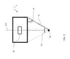
- FIG. 3illustrates schematically an upper view of a retail unit according to some embodiments of the present disclosure.
- FIG. 4illustrates a retail system according to some embodiments of the present disclosure.
- non-transitoryis used herein to exclude transitory, propagating signals, but to otherwise include any volatile or non-volatile computer memory technology suitable to the application.
- the phrase “for example,” “such as”, “for instance” and variants thereofdescribe non-limiting embodiments of the presently disclosed subject matter.
- Reference in the specification to “one case”, “some cases”, “other cases” or variants thereofmeans that a particular feature, structure or characteristic described in connection with the embodiment(s) is included in at least one embodiment of the presently disclosed subject matter.
- the appearance of the phrase “one case”, “some cases”, “other cases” or variants thereofdoes not necessarily refer to the same embodiment(s).
- FIG. 1illustrates steps of a method of monitoring (or inspecting) a retail unit according to embodiments of the present disclosure.
- the retail unitmay comprise a display module being capable of accommodating retail items.
- the display modulemay be housed in a housing structure.
- the housing structuremay define an inner volume for housing the display module and an access opening enabling inserting/removing retail items to/from the display module.
- the retail unitmay be a refrigerator or a cabinet provided with a shelving unit.
- the retail unitmay further comprise a door module configured for pivoting away from the display module.
- the door modulemay be operated (positioned) in an open state and in a closed state.
- the door moduleIn the closed state, the door module may face an access opening of the display module and in the open state, at least a part of the door module may be distant from the access opening.
- the access openingmay generally be understood as a doorway or an interface surface between the door module and the display module.
- the door modulemay actually comprise a door panel hinged to a peripheral portion of the display module. It is noted that the door module may not comprise a door panel i.e. the door module may consist of a frame.
- an imaging modulemay be coupled to the door module and configured to image the display module thereby allowing imaging of the retail items intended to be disposed in the display module.
- the imaging modulemay comprise one or more cameras mounted on the inner side of the door module (i.e.
- the access opening of the display modulemay be understood as an entrance surface to the display module enabling to insert or remove retail items in the display module.
- the access openingextends in a plane (i.e. has a plane shape like a disk or a plate) and the imaging module comprises one or more imaging sensors and the line of sight of the imaging sensors is configured so as to be perpendicular to the access opening plane when the door module is open at a predetermined opening angle.
- an open state of the door modulemay be detected.
- the opening of the door modulemay be detected using a switch or by detecting a change in a stream of images acquired by the imaging module, as will be explained later with reference to FIGS. 2A-2B .
- an opening detection modulemay enable to detect an opening level of the door module.
- the opening detection modulemay enable to detect if the door module has been pivoted away of the display module of an angle above a predetermined opening angle threshold and/or for a duration above a predetermined opening duration threshold.
- a set of images of the display modulemay be acquired by the imaging module.
- the imaging modulemay image continuously and step S 110 may comprise increasing the image acquisition frequency.
- the image acquisitionmay be triggered by the opening detection.
- the image acquisitionmay be stopped by detection of the door module closing or may be automatically triggered after a predetermined duration from the door opening detection time.
- the acquired imagesmay be forwarded to a processor module for further image processing.
- the set of acquired imagesmay be processed by the processor module.
- the processingmay enable to stitch (mix) images acquired simultaneously by the imaging sensors of the imaging module so as to increase a Field Of View (FOV) thereby leading to obtaining a set of stitched images.
- FOVField Of View
- the set of mixed imagesmay be communicated to a remote control center.
- the remote control centermay perform further analysis on the communicated images so as to determine how the retail items are assorted in the display module for assessing whether or not the retail unit complies with predefined assortment rules.
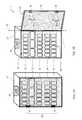
- FIGS. 2A and 2Billustrate a retail unit 1 according to some embodiments of the present disclosure.
- the retail unit 1comprises a display module 20 , a door module 30 , an imaging module 40 and a processor module 50 .
- FIG. 2Ashows a retail unit with the door module 30 open while FIG. 2B shows the retail unit with the door module 30 closed. It is noted that, even though the illustrated embodiment refers to a retail unit 1 in the form of a refrigerator, the features described herein below can be extended to different types of retail units such as all kinds of cabinets.
- the display module 20is capable of accommodating one or more retail items 10 .
- the display module 20may comprise one or more shelves 21 - 25 .
- the retail unit 1may further comprise a housing structure 27 (also referred to generally as housing) partially enclosing the display module 20 .
- the housing 27may comprise an access opening enabling a user to access the one or more shelves 21 - 25 so as to allow seizing of a retail item from the one or more shelves 21 - 25 .
- the housing 27 and the display module 20may define a structure in which the retail items are intended to be accommodated and the access opening may be defined as an aperture (or an entrance surface) of the housing enabling to access the retail items.
- the one or more shelves 21 - 25may be disposed in parallel within the housing 27 and may be capable of storing and/or displaying the one or more retail items 10 .
- the one or more retail itemsmay for example comprise drinks, food products, eyewear, medicine, etc.
- the door module 30is configured to close at least a part of the access opening.
- the door module 30may comprise a door panel 31 .
- the door panel 31may be transparent so as to allow people standing in front of the retail unit 1 to see the retail items 10 intended to be accommodated in the retail unit 1 .
- the door module 30may comprise a handle (not shown) and may be opened and closed upon operation of the handle by a user.
- the door panel 31may be configured to pivot away from the access opening of the display module 20 .
- the door panel 31may further be configured to close the access opening when the door module 30 is operated.
- a hinge mechanism(not shown) may be positioned on a peripheral portion of the access opening so as to define a pivot axis ⁇ of the door panel 31 .
- the imaging module 40may be coupled to the door module 30 and configured to acquire images of the display module 20 . More precisely, the imaging module 40 may be configured for imaging the one or more retail items 10 when the one or more retail items 10 are accommodated in the display module 20 .
- the imaging module 40may be arranged on the side of the door panel 31 facing the display module 20 . Arranging the imaging module 40 as described enables monitoring enclosed display modules, particularly for brand management purposes. In fact, monitoring enclosed cabinets is generally difficult because either the door is closed and it is not possible to image through the door (for example because the door is opaque or because frost deposited on the door surface causes image distortion), or the door is open by a user but the user stands in front of the display module and obstructs (obscures) the imaging. Therefore, arranging the imaging module as previously described notably enables to reduce image obstruction by users removing/inserting items from/into the display module 20 .
- the imaging module 40may comprise one or more imaging sensors 41 , 42 .
- the FOV of the imaging module 40may enable to image the access opening.
- the FOV of the imaging sensorsmay overlap so as to enable stitching of images acquired simultaneously.
- the imaging sensors 41 , 42may for example be digital cameras with FOV of 75*60 degrees.
- the FOV in one directionmay correspond to a width of the one or more shelves.
- the one or more imaging sensors 41 , 42may each be mounted on the door panel 31 so that a line of sight 415 of said imaging sensors be perpendicular to the access opening when the door panel 31 is open at a predetermined opening angle ⁇ .
- Thisenables to configure the imaging sensors 41 , 42 so as to “face” the access opening when the imaging sensors 41 , 42 are at a predetermined distance from the access opening and thereby increases the filed of view.
- the opening angle ⁇may be set between 45° to 75°, preferably around 60°.
- this angle rangecorresponds to the position people usually assume when holding the door open for removing or inserting items in a cabinet. Therefore, by configuring the imaging sensors so as to face the access opening at a predetermined angle within the aforementioned angle range, distortions due to door motion are advantageously reduced and imaging is improved. Furthermore, the one or more imaging sensors 41 , 42 may be configured so that the field of views 411 , 412 of the one or more imaging sensors 41 , 42 enable imaging of the whole access opening when the door panel 31 is open at the predetermined opening angle ⁇ . The one or more imaging sensors 41 , 42 may be arranged in a peripheral portion of the door panel 31 .
- the imaging sensorsmay be arranged on a side of the door panel 31 opposite to a side of the pivot axis ⁇ .
- the Applicanthas found that, in some embodiments in which two imaging sensors 41 , 42 are placed on the side of the door panel 31 opposite to the pivot axis ⁇ , it is advantageous to position the imaging sensors respectively in the first third and in the last third of the door panel length, wherein the length of the door panel 31 is defined along a direction parallel to the pivot axis ⁇ direction. This notably enables to further reduce imaging obstruction.
- At least one imaging sensoris positioned on the side of the door panel 31 opposite to the pivot axis ⁇ , it is advantageous to position the imaging sensor either in the first or in the last third of the door panel length. Therefore, advantageously, at least one imaging sensor may be positioned either in the first or in the last third of the door panel length.
- the one or more imaging sensors 41 , 42may be mounted in one or more corresponding sensor housings.
- the sensor housingsmay be mounted on the inside door panel 31 .
- the sensor housingsmay allow for adjustment and calibration of the angle of the imaging sensor in two perpendicular planes.
- the sensor housingmay allow for an angle adjustment of about 60° in either of the two perpendicular planes.
- the imaging sensors 41 , 42may be configured to be activated only upon detection of the opening of the door module 20 . This enables to reduce the amount of images to acquire and/or to communicate and/or to store. Alternatively, the imaging sensors 41 , 42 may be configured for continuously acquiring images at a predetermined frequency and be further configured to increase image frequency acquisition upon detection of the opening of the door module. An increased image acquisition frequency may be of around 15-17 images per second as a continuous image acquisition frequency may be of around 1-2 images per second. The series of images acquired between an opening and a subsequent closing of the door module may be recorded as an event and the images within each event may be numbered in sequence. All imaging sensors on the door module may take corresponding images that are identified in sequence of each event i.e.
- the retail unitfurther comprises a switch that connects when the door module is open and disconnects when the door module is closed so as to detect door module opening.
- motion detectionmay be performed by successive images analysis.
- the processor module 50is connected to the one or more imaging sensors 41 , 42 and is configured to receive the images acquired by said imaging sensors 41 , 42 .
- the one or more imaging sensors 41 , 42are connected to the processor module 50 via a mini Universal Serial Bus (USB) connector and one or more USB cables that may additionally power the imaging sensors 41 , 42 .
- the one or more USB cablesmay be tucked into a gasket around the door panel in order to conceal them and to avoid interfering with the movement of the door panel.
- the processor module 50may comprise a mini Personal Computer (PC) with one or more USB inputs on the motherboard (for example 6 to 8 inputs).
- the processor module 50may use Solid State Drive (SSD) memory and may have a specially LinuxTM based operating system.
- SSDSolid State Drive
- the processor module 50may be powered by an external source and may supply power to the imaging sensors 41 , 42 via the USB cables.
- the processor module 50may be housed in a compact casing that can be easily mounted on the top or side of a refrigerator.
- the processor modulemay be concealed behind a commercial banner.
- the processor module 50may be configured for performing image processing.
- the processor module 50may be configured to detect a change between two successive images received from the same imaging sensor so as to detect opening and closing of the door module.
- the processor module 50may be configured for stitching images received by different imaging sensors at the same instant so as to increase the FOV and allow reconstructing complete images of the access opening.
- the processor module 50may be configured for communicating data to a remote control center.
- the processor module 50may connect to the Internet via a wire or wireless connection such as 3G/4G/Wifi/Wimax, etc.
- a wireless connectionmay be connected directly to the motherboard or via a USB port.
- the 3Gmay use a local 3G SIM card in order to connect to the network and allow the processor module 50 to upload either the acquired images or the mixed images to the remote control center. Once the images are uploaded to the remote control center, the images may be processed and items accommodated on the display module 20 can be analyzed to check if item assortment rules are respected.
- the Internet connectionmay also allow for remote software update of the processor module 50 .
- a power adapter for 110/220Vmay power the processor module 50 and the imaging sensors 41 , 42 .
- FIG. 4illustrates a retail system 2 according to some embodiments of the present disclosure.
- the retail system 2comprises two retail units as previously described. It is understood that generally a retail system may comprise more than two retail units. Further, it is also noted that a single processor module may be used in a retail system comprising two or more retail units.
- each door moduleis mounted with an imaging module which are all connected to the same processor module.
- a round robin algorithm for sampling images from all the camerasis implemented for motion detection. This enables to handle the feed from the multiple imaging sensors. Once motion is detected the processor module may focus on the opened door until motion stops. Thereafter, the round robin algorithm may be resumed. The purpose of this process is to focus both processing power and camera capturing capabilities on the most relevant action, which in turns enable us to maximize the system capabilities.
Landscapes
- Closed-Circuit Television Systems (AREA)
Abstract
Description
Claims (13)
Applications Claiming Priority (3)
| Application Number | Priority Date | Filing Date | Title |
|---|---|---|---|
| IL22614613 | 2013-05-05 | ||
| IL226146 | 2013-05-05 | ||
| PCT/IL2014/050378WO2014181324A1 (en) | 2013-05-05 | 2014-04-24 | System and method of monitoring retail units |
Publications (2)
| Publication Number | Publication Date |
|---|---|
| US20160143459A1 US20160143459A1 (en) | 2016-05-26 |
| US10368662B2true US10368662B2 (en) | 2019-08-06 |
Family
ID=50842304
Family Applications (1)
| Application Number | Title | Priority Date | Filing Date |
|---|---|---|---|
| US14/888,978Active2035-12-09US10368662B2 (en) | 2013-05-05 | 2014-04-24 | System and method of monitoring retail units |
Country Status (3)
| Country | Link |
|---|---|
| US (1) | US10368662B2 (en) |
| EP (1) | EP2994025B1 (en) |
| WO (1) | WO2014181324A1 (en) |
Families Citing this family (15)
| Publication number | Priority date | Publication date | Assignee | Title |
|---|---|---|---|---|
| WO2014181324A1 (en) | 2013-05-05 | 2014-11-13 | Trax Technology Solutions Pte Ltd. | System and method of monitoring retail units |
| US10387996B2 (en) | 2014-02-02 | 2019-08-20 | Trax Technology Solutions Pte Ltd. | System and method for panoramic image processing |
| US10402777B2 (en) | 2014-06-18 | 2019-09-03 | Trax Technology Solutions Pte Ltd. | Method and a system for object recognition |
| US20190042995A1 (en)* | 2017-08-03 | 2019-02-07 | Walmart Apollo, Llc | Automated Item Assortment System |
| US11698219B2 (en) | 2017-08-10 | 2023-07-11 | Cooler Screens Inc. | Smart movable closure system for cooling cabinet |
| US11763252B2 (en) | 2017-08-10 | 2023-09-19 | Cooler Screens Inc. | Intelligent marketing and advertising platform |
| US11768030B2 (en) | 2017-08-10 | 2023-09-26 | Cooler Screens Inc. | Smart movable closure system for cooling cabinet |
| US12118510B2 (en) | 2017-08-10 | 2024-10-15 | Cooler Screens Inc. | Intelligent marketing and advertising platform |
| US10672032B2 (en) | 2017-08-10 | 2020-06-02 | Cooler Screens Inc. | Intelligent marketing and advertising platform |
| US10769666B2 (en) | 2017-08-10 | 2020-09-08 | Cooler Screens Inc. | Intelligent marketing and advertising platform |
| WO2019143810A1 (en) | 2018-01-17 | 2019-07-25 | Anthony, Inc. | Door for mounting a removable electronic display |
| US11141004B1 (en) | 2018-10-03 | 2021-10-12 | Anthony, Inc. | Display case door with interior facing camera |
| CN119515484A (en)* | 2018-12-17 | 2025-02-25 | 酷乐屏幕公司 | Intelligent marketing and advertising platform |
| US10514722B1 (en) | 2019-03-29 | 2019-12-24 | Anthony, Inc. | Door for mounting a removable electronic display |
| WO2021150406A1 (en)* | 2019-12-17 | 2021-07-29 | Cooler Screens Inc. | Smart movable closure system for cooling cabinet |
Citations (56)
| Publication number | Priority date | Publication date | Assignee | Title |
|---|---|---|---|---|
| US6195122B1 (en) | 1995-01-31 | 2001-02-27 | Robert Vincent | Spatial referenced photography |
| JP2002295959A (en) | 2001-03-28 | 2002-10-09 | Seiko Epson Corp | Refrigerator with shooting device |
| JP2003004366A (en)* | 2001-06-20 | 2003-01-08 | Hitachi Ltd | Refrigerator with internal state transfer device |
| US6618511B1 (en) | 1999-12-31 | 2003-09-09 | Stmicroelectronics, Inc. | Perspective correction for panoramic digital camera with remote processing |
| FR2851833A1 (en) | 2003-02-27 | 2004-09-03 | Alcon Diaz Consulting | METHOD FOR MEASURING THE LINEAR OF A PRODUCT ON A SHELF |
| US20050256391A1 (en) | 2004-05-14 | 2005-11-17 | Canon Kabushiki Kaisha | Information processing method and apparatus for finding position and orientation of targeted object |
| US7031948B2 (en) | 2001-10-05 | 2006-04-18 | Lee Shih-Jong J | Regulation of hierarchic decisions in intelligent systems |
| US20070025723A1 (en) | 2005-07-28 | 2007-02-01 | Microsoft Corporation | Real-time preview for panoramic images |
| US20070031062A1 (en) | 2005-08-04 | 2007-02-08 | Microsoft Corporation | Video registration and image sequence stitching |
| JP2007046833A (en) | 2005-08-09 | 2007-02-22 | Funai Electric Co Ltd | Article storage, article storage monitoring system, and refrigerator monitoring system |
| US20070070233A1 (en) | 2005-09-28 | 2007-03-29 | Patterson Raul D | System and method for correlating captured images with their site locations on maps |
| US20070081081A1 (en) | 2005-10-07 | 2007-04-12 | Cheng Brett A | Automated multi-frame image capture for panorama stitching using motion sensor |
| US7210136B2 (en) | 2002-05-24 | 2007-04-24 | Avaya Inc. | Parser generation based on example document |
| US7287731B2 (en) | 2001-04-20 | 2007-10-30 | Camera Dynamics Inc. | Heavy-duty stabilized camera head with camera position sensing |
| US20080074489A1 (en) | 2006-09-27 | 2008-03-27 | Samsung Electronics Co., Ltd. | Apparatus, method, and medium for generating panoramic image |
| WO2008107150A1 (en) | 2007-03-02 | 2008-09-12 | Baumer Electric Ag | Monitoring system, in particular for analyzing the fill level of shelves |
| US20090003708A1 (en) | 2003-06-26 | 2009-01-01 | Fotonation Ireland Limited | Modification of post-viewing parameters for digital images using image region or feature information |
| WO2009027835A2 (en) | 2007-08-31 | 2009-03-05 | Accenture Global Services Gmbh | Detection of stock out conditions based on image processing |
| US20090192921A1 (en) | 2008-01-24 | 2009-07-30 | Michael Alan Hicks | Methods and apparatus to survey a retail environment |
| US7620909B2 (en) | 1999-05-12 | 2009-11-17 | Imove Inc. | Interactive image seamer for panoramic images |
| US20100035637A1 (en) | 2007-08-07 | 2010-02-11 | Palm, Inc. | Displaying image data and geographic element data |
| US20100046791A1 (en)* | 2008-08-08 | 2010-02-25 | Snap-On Incorporated | Image-based inventory control system using advanced image recognition |
| US20100097443A1 (en) | 2008-10-16 | 2010-04-22 | Peter Lablans | Controller in a Camera for Creating a Panoramic Image |
| US20100171826A1 (en) | 2006-04-12 | 2010-07-08 | Store Eyes, Inc. | Method for measuring retail display and compliance |
| US20100222099A1 (en) | 2009-02-27 | 2010-09-02 | Research In Motion Limited | Mobile wireless communications device with orientation sensing and related methods |
| US20100321470A1 (en) | 2009-06-22 | 2010-12-23 | Fujifilm Corporation | Imaging apparatus and control method therefor |
| US20110007154A1 (en) | 2008-02-12 | 2011-01-13 | Michael Vogel | Determining coordinates of a target in relation to a survey instrument having a camera |
| US20110011936A1 (en)* | 2007-08-31 | 2011-01-20 | Accenture Global Services Gmbh | Digital point-of-sale analyzer |
| US7903883B2 (en) | 2007-03-30 | 2011-03-08 | Microsoft Corporation | Local bi-gram model for object recognition |
| US20110079083A1 (en) | 2008-06-05 | 2011-04-07 | Koninklijke Philips Electronics N.V. | Extended field of view ultrasonic imaging with guided efov scanning |
| US20110173082A1 (en) | 2010-01-11 | 2011-07-14 | Vendmore Systems, Llc | Smart visi-coolers |
| US20110173100A1 (en) | 2000-11-06 | 2011-07-14 | Boncyk Wayne C | Object Information Derived from Object Images |
| US20120027390A1 (en) | 2010-07-29 | 2012-02-02 | Canon Kabushiki Kaisha | Image capture apparatus and method of controlling the same |
| US8131086B2 (en) | 2008-09-24 | 2012-03-06 | Microsoft Corporation | Kernelized spatial-contextual image classification |
| US20120075411A1 (en) | 2010-09-27 | 2012-03-29 | Casio Computer Co., Ltd. | Image capturing apparatus capable of capturing a panoramic image |
| US20120243739A1 (en) | 2011-03-25 | 2012-09-27 | Masaki Fukuchi | Information processing device, object recognition method, program, and terminal device |
| WO2012155121A2 (en) | 2011-05-11 | 2012-11-15 | University Of Florida Research Foundation, Inc. | Systems and methods for estimating the geographic location at which image data was captured |
| US20120293607A1 (en) | 2011-05-17 | 2012-11-22 | Apple Inc. | Panorama Processing |
| US20120300019A1 (en) | 2011-05-25 | 2012-11-29 | Microsoft Corporation | Orientation-based generation of panoramic fields |
| US20130070090A1 (en)* | 2011-09-16 | 2013-03-21 | Mckesson Automation Inc. | Systems, methods and computer program product for monitoring interactions with a medication storage device |
| US8515207B2 (en) | 2007-05-25 | 2013-08-20 | Google Inc. | Annotations in panoramic images, and applications thereof |
| WO2013151553A1 (en)* | 2012-04-05 | 2013-10-10 | Intel Corporation | Method and apparatus for managing product placement on store shelf |
| US8559766B2 (en) | 2011-08-16 | 2013-10-15 | iParse, LLC | Automatic image capture |
| US20140009382A1 (en) | 2012-07-03 | 2014-01-09 | Wistron Corporation | Method and Electronic Device for Object Recognition, and Method for Acquiring Depth Information of an Object |
| US20140052555A1 (en) | 2011-08-30 | 2014-02-20 | Digimarc Corporation | Methods and arrangements for identifying objects |
| US20140297487A1 (en)* | 2013-03-26 | 2014-10-02 | 3 Strike, Llc | Storage container with inventory control |
| WO2014181323A1 (en) | 2013-05-05 | 2014-11-13 | Trax Technology Solutions Pte Ltd. | System and method of retail image analysis |
| US20150139535A1 (en) | 2013-11-18 | 2015-05-21 | Nant Holdings Ip, Llc | Silhouette-based object and texture alignment, systems and methods |
| US20150141759A1 (en) | 2012-06-27 | 2015-05-21 | Camplex, Inc. | Interface for viewing video from cameras on a surgical visualization system |
| WO2015083170A1 (en) | 2013-12-05 | 2015-06-11 | Trax Technology Solutions Pte. Ltd. | Fine grained recognition method and system |
| US20150187101A1 (en) | 2013-12-30 | 2015-07-02 | Trax Technology Solutions Pte Ltd. | Device and method with orientation indication |
| US20150193909A1 (en) | 2014-01-09 | 2015-07-09 | Trax Technology Solutions Pte Ltd. | Method and device for panoramic image processing |
| WO2015114621A1 (en) | 2014-02-02 | 2015-08-06 | Trax Technology Solutions Pte. Ltd. | System and method for panoramic image processing |
| US9160899B1 (en) | 2011-12-23 | 2015-10-13 | H4 Engineering, Inc. | Feedback and manual remote control system and method for automatic video recording |
| WO2015193877A1 (en) | 2014-06-18 | 2015-12-23 | Trax Technology Solutions Pte. Ltd. | A method and a system for object recognition |
| US20160143459A1 (en) | 2013-05-05 | 2016-05-26 | Trax Technology Solutions Pte Ltd. | System and method of monitoring retail units |
- 2014
- 2014-04-24WOPCT/IL2014/050378patent/WO2014181324A1/enactiveApplication Filing
- 2014-04-24USUS14/888,978patent/US10368662B2/enactiveActive
- 2014-04-24EPEP14727260.3Apatent/EP2994025B1/enactiveActive
Patent Citations (57)
| Publication number | Priority date | Publication date | Assignee | Title |
|---|---|---|---|---|
| US6195122B1 (en) | 1995-01-31 | 2001-02-27 | Robert Vincent | Spatial referenced photography |
| US7620909B2 (en) | 1999-05-12 | 2009-11-17 | Imove Inc. | Interactive image seamer for panoramic images |
| US6618511B1 (en) | 1999-12-31 | 2003-09-09 | Stmicroelectronics, Inc. | Perspective correction for panoramic digital camera with remote processing |
| US20110173100A1 (en) | 2000-11-06 | 2011-07-14 | Boncyk Wayne C | Object Information Derived from Object Images |
| JP2002295959A (en) | 2001-03-28 | 2002-10-09 | Seiko Epson Corp | Refrigerator with shooting device |
| US7287731B2 (en) | 2001-04-20 | 2007-10-30 | Camera Dynamics Inc. | Heavy-duty stabilized camera head with camera position sensing |
| JP2003004366A (en)* | 2001-06-20 | 2003-01-08 | Hitachi Ltd | Refrigerator with internal state transfer device |
| US7031948B2 (en) | 2001-10-05 | 2006-04-18 | Lee Shih-Jong J | Regulation of hierarchic decisions in intelligent systems |
| US7210136B2 (en) | 2002-05-24 | 2007-04-24 | Avaya Inc. | Parser generation based on example document |
| FR2851833A1 (en) | 2003-02-27 | 2004-09-03 | Alcon Diaz Consulting | METHOD FOR MEASURING THE LINEAR OF A PRODUCT ON A SHELF |
| US20090003708A1 (en) | 2003-06-26 | 2009-01-01 | Fotonation Ireland Limited | Modification of post-viewing parameters for digital images using image region or feature information |
| US20050256391A1 (en) | 2004-05-14 | 2005-11-17 | Canon Kabushiki Kaisha | Information processing method and apparatus for finding position and orientation of targeted object |
| US20070025723A1 (en) | 2005-07-28 | 2007-02-01 | Microsoft Corporation | Real-time preview for panoramic images |
| US20070031062A1 (en) | 2005-08-04 | 2007-02-08 | Microsoft Corporation | Video registration and image sequence stitching |
| JP2007046833A (en) | 2005-08-09 | 2007-02-22 | Funai Electric Co Ltd | Article storage, article storage monitoring system, and refrigerator monitoring system |
| US20070070233A1 (en) | 2005-09-28 | 2007-03-29 | Patterson Raul D | System and method for correlating captured images with their site locations on maps |
| US20070081081A1 (en) | 2005-10-07 | 2007-04-12 | Cheng Brett A | Automated multi-frame image capture for panorama stitching using motion sensor |
| US20100171826A1 (en) | 2006-04-12 | 2010-07-08 | Store Eyes, Inc. | Method for measuring retail display and compliance |
| US20080074489A1 (en) | 2006-09-27 | 2008-03-27 | Samsung Electronics Co., Ltd. | Apparatus, method, and medium for generating panoramic image |
| WO2008107150A1 (en) | 2007-03-02 | 2008-09-12 | Baumer Electric Ag | Monitoring system, in particular for analyzing the fill level of shelves |
| US7903883B2 (en) | 2007-03-30 | 2011-03-08 | Microsoft Corporation | Local bi-gram model for object recognition |
| US8515207B2 (en) | 2007-05-25 | 2013-08-20 | Google Inc. | Annotations in panoramic images, and applications thereof |
| US20100035637A1 (en) | 2007-08-07 | 2010-02-11 | Palm, Inc. | Displaying image data and geographic element data |
| US20110011936A1 (en)* | 2007-08-31 | 2011-01-20 | Accenture Global Services Gmbh | Digital point-of-sale analyzer |
| WO2009027835A2 (en) | 2007-08-31 | 2009-03-05 | Accenture Global Services Gmbh | Detection of stock out conditions based on image processing |
| US20090192921A1 (en) | 2008-01-24 | 2009-07-30 | Michael Alan Hicks | Methods and apparatus to survey a retail environment |
| US20110007154A1 (en) | 2008-02-12 | 2011-01-13 | Michael Vogel | Determining coordinates of a target in relation to a survey instrument having a camera |
| US20110079083A1 (en) | 2008-06-05 | 2011-04-07 | Koninklijke Philips Electronics N.V. | Extended field of view ultrasonic imaging with guided efov scanning |
| US20100046791A1 (en)* | 2008-08-08 | 2010-02-25 | Snap-On Incorporated | Image-based inventory control system using advanced image recognition |
| US8131086B2 (en) | 2008-09-24 | 2012-03-06 | Microsoft Corporation | Kernelized spatial-contextual image classification |
| US20100097443A1 (en) | 2008-10-16 | 2010-04-22 | Peter Lablans | Controller in a Camera for Creating a Panoramic Image |
| US20100222099A1 (en) | 2009-02-27 | 2010-09-02 | Research In Motion Limited | Mobile wireless communications device with orientation sensing and related methods |
| US20100321470A1 (en) | 2009-06-22 | 2010-12-23 | Fujifilm Corporation | Imaging apparatus and control method therefor |
| US20110173082A1 (en) | 2010-01-11 | 2011-07-14 | Vendmore Systems, Llc | Smart visi-coolers |
| US20120027390A1 (en) | 2010-07-29 | 2012-02-02 | Canon Kabushiki Kaisha | Image capture apparatus and method of controlling the same |
| US20120075411A1 (en) | 2010-09-27 | 2012-03-29 | Casio Computer Co., Ltd. | Image capturing apparatus capable of capturing a panoramic image |
| US20120243739A1 (en) | 2011-03-25 | 2012-09-27 | Masaki Fukuchi | Information processing device, object recognition method, program, and terminal device |
| WO2012155121A2 (en) | 2011-05-11 | 2012-11-15 | University Of Florida Research Foundation, Inc. | Systems and methods for estimating the geographic location at which image data was captured |
| US20120293607A1 (en) | 2011-05-17 | 2012-11-22 | Apple Inc. | Panorama Processing |
| US20120300019A1 (en) | 2011-05-25 | 2012-11-29 | Microsoft Corporation | Orientation-based generation of panoramic fields |
| US8559766B2 (en) | 2011-08-16 | 2013-10-15 | iParse, LLC | Automatic image capture |
| US20140052555A1 (en) | 2011-08-30 | 2014-02-20 | Digimarc Corporation | Methods and arrangements for identifying objects |
| US20130070090A1 (en)* | 2011-09-16 | 2013-03-21 | Mckesson Automation Inc. | Systems, methods and computer program product for monitoring interactions with a medication storage device |
| US9160899B1 (en) | 2011-12-23 | 2015-10-13 | H4 Engineering, Inc. | Feedback and manual remote control system and method for automatic video recording |
| US20140006229A1 (en)* | 2012-04-05 | 2014-01-02 | Thomas A. Birch | Method and Apparatus for Managing Product Placement on Store Shelf |
| WO2013151553A1 (en)* | 2012-04-05 | 2013-10-10 | Intel Corporation | Method and apparatus for managing product placement on store shelf |
| US20150141759A1 (en) | 2012-06-27 | 2015-05-21 | Camplex, Inc. | Interface for viewing video from cameras on a surgical visualization system |
| US20140009382A1 (en) | 2012-07-03 | 2014-01-09 | Wistron Corporation | Method and Electronic Device for Object Recognition, and Method for Acquiring Depth Information of an Object |
| US20140297487A1 (en)* | 2013-03-26 | 2014-10-02 | 3 Strike, Llc | Storage container with inventory control |
| WO2014181323A1 (en) | 2013-05-05 | 2014-11-13 | Trax Technology Solutions Pte Ltd. | System and method of retail image analysis |
| US20160143459A1 (en) | 2013-05-05 | 2016-05-26 | Trax Technology Solutions Pte Ltd. | System and method of monitoring retail units |
| US20150139535A1 (en) | 2013-11-18 | 2015-05-21 | Nant Holdings Ip, Llc | Silhouette-based object and texture alignment, systems and methods |
| WO2015083170A1 (en) | 2013-12-05 | 2015-06-11 | Trax Technology Solutions Pte. Ltd. | Fine grained recognition method and system |
| US20150187101A1 (en) | 2013-12-30 | 2015-07-02 | Trax Technology Solutions Pte Ltd. | Device and method with orientation indication |
| US20150193909A1 (en) | 2014-01-09 | 2015-07-09 | Trax Technology Solutions Pte Ltd. | Method and device for panoramic image processing |
| WO2015114621A1 (en) | 2014-02-02 | 2015-08-06 | Trax Technology Solutions Pte. Ltd. | System and method for panoramic image processing |
| WO2015193877A1 (en) | 2014-06-18 | 2015-12-23 | Trax Technology Solutions Pte. Ltd. | A method and a system for object recognition |
Non-Patent Citations (7)
| Title |
|---|
| Changchang Wu et al.; "3D Model Matching With Viewpoint-Invariant Patches (VIP)", Computer Vision and Pattern Recognition, CVPR 2008, IEEE Conference, pp. 1-8 (2008). |
| International Search Report and Written Opinion from the Israel Patent Office for International Application No. PCT/IL2014/050378, dated Aug. 7, 2014. |
| International Search Report and Written Opinion from the Israel Patent Office for International Application No. PCT/IL2014/051061, dated Mar. 26, 2015. |
| International Search Report and Written Opinion from the Israel Patent Office for International Application No. PCT/IL2014/051127, dated May 15, 2015. |
| International Search Report and Written Opinion from the Israel Patent Office for International Application No. PCT/IL2015/050070, dated Apr. 28, 2015. |
| International Search Report from the Israel Patent Office for International Application No. PCT/IL2014/050377, dated Jul. 25, 2014. |
| International Search Report from the Israel Patent Office for International Application No. PCT/IL2015/050576, dated Oct. 14, 2015. |
Also Published As
| Publication number | Publication date |
|---|---|
| WO2014181324A1 (en) | 2014-11-13 |
| EP2994025C0 (en) | 2023-09-20 |
| US20160143459A1 (en) | 2016-05-26 |
| EP2994025B1 (en) | 2023-09-20 |
| EP2994025A1 (en) | 2016-03-16 |
Similar Documents
| Publication | Publication Date | Title |
|---|---|---|
| US10368662B2 (en) | System and method of monitoring retail units | |
| WO2014181323A1 (en) | System and method of retail image analysis | |
| US12303045B1 (en) | Display case door with interior facing camera | |
| CN106062776B (en) | Polarized Gaze Tracking | |
| US9978290B2 (en) | Identifying a change in a home environment | |
| US10271017B2 (en) | System and method for generating an activity summary of a person | |
| US12211062B2 (en) | Smart platform counter display system | |
| KR102586911B1 (en) | Intelligent Marketing and Advertising Platform | |
| US10825031B2 (en) | System for observing and analyzing customer opinion | |
| NO20120607A1 (en) | Display unit with Pointmdeia technology; Point media device - PE | |
| US20140168396A1 (en) | Method for viewing contents of a refrigerator appliance | |
| CN108764998B (en) | Intelligent display device and intelligent display method | |
| CN111666792A (en) | Image recognition method, image acquisition and recognition method and commodity recognition method | |
| CN114202537A (en) | Camera imaging defect detection method, display cabinet and storage medium | |
| CN107277649A (en) | Express delivery cabinet and its monitoring method | |
| US20140002646A1 (en) | Bottom of the basket surveillance system for shopping carts | |
| US20170363348A1 (en) | System and method of refrigerator content tracking | |
| CN114220065A (en) | Aisle detection method in showcase, showcase and storage medium | |
| CN217484926U (en) | Sales counter | |
| KR20180077881A (en) | System for intelligent exhibition based on transparent display and method thereof | |
| US20230058922A1 (en) | Appliance with collocated cameras | |
| US20230057240A1 (en) | Four camera system for a refrigerator appliance | |
| KR20230166854A (en) | Method and apparatus for recognizing based on camera arranged on both sides of the front for each floor of showcase | |
| CN109993927B (en) | Door and method for controlling door | |
| CN115100981A (en) | Display screen, control system, electric appliance with display screen and refrigerator with display screen |
Legal Events
| Date | Code | Title | Description |
|---|---|---|---|
| AS | Assignment | Owner name:TRAX TECHNOLOGIES SOLUTIONS PTE LTD, SINGAPORE Free format text:ASSIGNMENT OF ASSIGNORS INTEREST;ASSIGNOR:CLEIN, SHAVIT NOA;REEL/FRAME:045756/0099 Effective date:20140606 | |
| STPP | Information on status: patent application and granting procedure in general | Free format text:NOTICE OF ALLOWANCE MAILED -- APPLICATION RECEIVED IN OFFICE OF PUBLICATIONS | |
| FEPP | Fee payment procedure | Free format text:ENTITY STATUS SET TO UNDISCOUNTED (ORIGINAL EVENT CODE: BIG.); ENTITY STATUS OF PATENT OWNER: LARGE ENTITY | |
| STPP | Information on status: patent application and granting procedure in general | Free format text:PUBLICATIONS -- ISSUE FEE PAYMENT VERIFIED | |
| AS | Assignment | Owner name:PACIFIC WESTERN BANK, NORTH CAROLINA Free format text:SECURITY INTEREST;ASSIGNOR:TRAX TECHNOLOGY SOLUTIONS PTE LTD.;REEL/FRAME:049564/0715 Effective date:20190510 | |
| STCF | Information on status: patent grant | Free format text:PATENTED CASE | |
| AS | Assignment | Owner name:TRAX TECHNOLOGY SOLUTIONS PTE LTD., SINGAPORE Free format text:RELEASE BY SECURED PARTY;ASSIGNOR:PACIFIC WESTERN BANK;REEL/FRAME:052662/0568 Effective date:20200513 | |
| AS | Assignment | Owner name:JPMORGAN CHASE BANK, N.A., AS ADMINISTRATIVE AGENT, NEW YORK Free format text:SECURITY INTEREST;ASSIGNORS:TRAX TECHNOLOGY SOLUTIONS PTE. LTD.;SHOPKICK, INC.;CVDM SOLUTIONS SAS;AND OTHERS;REEL/FRAME:054048/0646 Effective date:20201013 | |
| AS | Assignment | Owner name:ALTER DOMUS (US) LLC, ILLINOIS Free format text:SECURITY INTEREST;ASSIGNORS:TRAX TECHNOLOGY PTE. LTD.;SHOPKICK, INC.;REEL/FRAME:058184/0438 Effective date:20211014 | |
| AS | Assignment | Owner name:TRAX RETAIL, INC., GEORGIA Free format text:RELEASE OF SECURITY INTEREST AT REEL/FRAME NO. 054048/0646;ASSIGNOR:JPMORGAN CHASE BANK, N.A., AS ADMINISTRATIVE AGENT;REEL/FRAME:057944/0338 Effective date:20211014 Owner name:CVDM SOLUTIONS SAS, FRANCE Free format text:RELEASE OF SECURITY INTEREST AT REEL/FRAME NO. 054048/0646;ASSIGNOR:JPMORGAN CHASE BANK, N.A., AS ADMINISTRATIVE AGENT;REEL/FRAME:057944/0338 Effective date:20211014 Owner name:SHOPKICK, INC., CALIFORNIA Free format text:RELEASE OF SECURITY INTEREST AT REEL/FRAME NO. 054048/0646;ASSIGNOR:JPMORGAN CHASE BANK, N.A., AS ADMINISTRATIVE AGENT;REEL/FRAME:057944/0338 Effective date:20211014 Owner name:TRAX TECHNOLOGY SOLUTIONS PTE. LTD, SINGAPORE Free format text:RELEASE OF SECURITY INTEREST AT REEL/FRAME NO. 054048/0646;ASSIGNOR:JPMORGAN CHASE BANK, N.A., AS ADMINISTRATIVE AGENT;REEL/FRAME:057944/0338 Effective date:20211014 | |
| MAFP | Maintenance fee payment | Free format text:PAYMENT OF MAINTENANCE FEE, 4TH YEAR, LARGE ENTITY (ORIGINAL EVENT CODE: M1551); ENTITY STATUS OF PATENT OWNER: LARGE ENTITY Year of fee payment:4 | |
| AS | Assignment | Owner name:COMPUTERSHARE TRUST COMPANY, N.A., AS ADMINISTRATIVE AGENT, MARYLAND Free format text:SECURITY INTEREST;ASSIGNORS:TRAX TECHNOLOGY SOLUTIONS PTE. LTD.;SHOPKICK, INC.;REEL/FRAME:065016/0744 Effective date:20230922 | |
| AS | Assignment | Owner name:SHOPKICK INC., COLORADO Free format text:RELEASE BY SECURED PARTY;ASSIGNOR:ALTER DOMUS (US) LLC;REEL/FRAME:065028/0871 Effective date:20230922 Owner name:TRAX TECHNOLOGY SOLUTIONS PTE. LTD., SINGAPORE Free format text:RELEASE BY SECURED PARTY;ASSIGNOR:ALTER DOMUS (US) LLC;REEL/FRAME:065028/0871 Effective date:20230922 |