US10365667B2 - Flow-path controllers and related systems - Google Patents
Flow-path controllers and related systemsDownload PDFInfo
- Publication number
- US10365667B2 US10365667B2US15/354,982US201615354982AUS10365667B2US 10365667 B2US10365667 B2US 10365667B2US 201615354982 AUS201615354982 AUS 201615354982AUS 10365667 B2US10365667 B2US 10365667B2
- Authority
- US
- United States
- Prior art keywords
- fluid
- liquid
- signal
- transfer system
- branch
- Prior art date
- Legal status (The legal status is an assumption and is not a legal conclusion. Google has not performed a legal analysis and makes no representation as to the accuracy of the status listed.)
- Active
Links
Images


Classifications
- G—PHYSICS
- G05—CONTROLLING; REGULATING
- G05D—SYSTEMS FOR CONTROLLING OR REGULATING NON-ELECTRIC VARIABLES
- G05D7/00—Control of flow
- G05D7/06—Control of flow characterised by the use of electric means
- G05D7/0617—Control of flow characterised by the use of electric means specially adapted for fluid materials
- G05D7/0629—Control of flow characterised by the use of electric means specially adapted for fluid materials characterised by the type of regulator means
- G05D7/0635—Control of flow characterised by the use of electric means specially adapted for fluid materials characterised by the type of regulator means by action on throttling means
- G—PHYSICS
- G06—COMPUTING OR CALCULATING; COUNTING
- G06F—ELECTRIC DIGITAL DATA PROCESSING
- G06F1/00—Details not covered by groups G06F3/00 - G06F13/00 and G06F21/00
- G06F1/16—Constructional details or arrangements
- G06F1/20—Cooling means
- G06F1/206—Cooling means comprising thermal management
- G—PHYSICS
- G06—COMPUTING OR CALCULATING; COUNTING
- G06F—ELECTRIC DIGITAL DATA PROCESSING
- G06F2200/00—Indexing scheme relating to G06F1/04 - G06F1/32
- G06F2200/20—Indexing scheme relating to G06F1/20
- G06F2200/201—Cooling arrangements using cooling fluid
Definitions
- the innovations and related subject matter disclosed hereinpertain to control of fluid-flow paths in heat-transfer systems, and more particularly, but not exclusively, to electro-mechanically actuated flow-path controllers, with automatically decoupleable couplers and electro-mechanically actuated valves being but two specific examples of disclosed flow-path controllers.
- Such actuatorscan be activated responsively to an alert or a command received from a controller.
- Such controllerscan issue the alert or command, for example, in response to a detected change in state of a given system.
- a leak detectorcan be configured to respond to a detected leak of a working fluid from a liquid-based heat transfer system, or a flow-rate sensor can be configured to detect a rate of flow of a fluid through a conduit.
- a controllercan issue an alert or a command over a bus responsively to a detected change in state (e.g., a detected leak or a detected change in flow rate).
- one or more electro-mechanical actuatorssuch as, for example, a linear or a rotary servo- or stepper-motor, can urge or pull against a linkage or other member arranged to terminate a fluid flow through a conduit, a channel, or other flow path.
- such an electro-mechanical actuatorcan cause one or more valves to open or to close, or cause a pair of matingly engaged couplers (sometimes referred to in the art as, for example, a “dripless quick-connect” or a “quick-disconnect”) to decouple from each other.
- a pair of matingly engaged couplerssometimes referred to in the art as, for example, a “dripless quick-connect” or a “quick-disconnect”
- Some detectors and control systemsare described in relation to cooling systems for electronic devices by way of example. Nonetheless, one or more of the innovations disclosed herein can be suitable for use in a variety of other control-system applications, as will be understood by those of ordinary skill in the art following a review of the present disclosure.
- a rate of heat transfer through a liquid-to-liquid or an air-to-liquid (or a liquid-to-air) heat exchangercan correspond to a rate of flow of a heat transfer medium (e.g., a liquid coolant) through the heat exchanger.
- a substantial excursion of fluid flow rate through a conduitcan indirectly indicate a leak upstream of the conduit, or a change in heat-transfer performance.
- flow-rate sensorsare generally considered to be incompatible with existing liquid-cooling systems suitable for computer systems.
- some known flow-rate sensorsare typically too large, too expensive, or both, to be incorporated into liquid-cooling systems suitable for widespread commercialization in connection with cooling systems for computer systems, or other systems.
- controllable, reconfigurable, or customizable fluid-flow pathscan be desirable in some instances, as when a leak is detected and/or a detected flow rate through a particular conduit, channel, or other fluid passage exceeds or falls below a selected threshold. For example, automatically isolating a branch of fluid circuit responsive to a detected leak could be desirable in an attempt to avoid damage to, for example, nearby electronic components.
- sensorsconfigured to detect a leak from a liquid cooling system.
- a monitoring systemconfigured to initiate an alert responsive to a leak detected by the leak detector.
- a needalso remains for a leak detector configured to be compatible with a control system for a computer system or other computing environment.
- flow-rate sensorsconfigured to detect or sense a rate of flow of a working fluid through a conduit, for example, a portion of a flow path through a portion of a liquid-cooling system.
- flow sensorsto emit a signal responsive to a detected or a sensed flow rate of the working fluid.
- This disclosurepertains generally to control systems, for example, detectors configured to issue an alert or a command to a controller in response to a detected change in state of a given system, electro-mechanically actuated flow-path controllers, with automatically decoupleable couplers and electro-mechanically actuated valves being but two specific examples of disclosed flow-path controllers, and combinations thereof.
- a disclosed control systemhas a sensor circuit configured to emit a simulated signal corresponding to a selected physical parameter as a proxy for an observed operational parameter different from the selected physical parameter.
- a controlleris configured to receive the simulated signal and to infer from the simulated signal a state of the observed operational parameter.
- An electro-mechanical actuatoris selectively activatable based at least in part on the inferred state of the observed operational parameter.
- the controllercan be configured to emit a command signal responsive to the state of the observed operational parameter and the electro-mechanical actuator can be selectively activatable responsively to the command signal.
- the simulated signalcan be a simulated fan-tachometer signal, and the selected physical parameter can be a fan speed.
- the sensoris a leak detector, and the observed operational parameter is a detected presence or a detected absence of a leak by the leak detector.
- the simulated signalcan be, for example, a simulated reproduction of a waveform emitted by a properly or an improperly operating, or a failed, fan.
- the selected physical parametercan be a rotational fan speed and the observed operational parameter can consist of one or more of an indicia of fluid level, an indicia of pressure, an indicia of electrical current, and an indicia of a presence or absence of moisture.
- the observed operational parametercan be an indicia of a presence or absence of a working fluid externally of a liquid-based heat-transfer system.
- the sensorcan include an electrical circuit configured to emit the simulated signal responsive to the indicia of a presence of the working fluid externally of the liquid-based heat transfer system, and the electro-mechanical actuator can be configured to decouple matingly engaged couplers or to close a valve to isolate a branch of a fluid circuit.
- methods of isolating a branch of a fluid circuit from a liquid-based heat-transfer systemare disclosed.
- a presence or an absence of a working fluidcan be sensed externally of a liquid-based heat-transfer system.
- An electro-mechanical actuatorcan be activated to close a valve and/or to decouple matingly engaged members of a fluid coupler.
- a signalcan be emitted responsive to the sensed presence or absence of the working fluid.
- the emitted signal in the sensed absence of the working fluidcan be, for example, a simulated tachometer signal of the type emitted by an operable fan.
- a branch of a fluid circuitcan be configured to convey a liquid from an inlet to the branch to an outlet from the branch.
- the inlet and the outletcan be fluidly coupled with a liquid supply and a liquid collector, respectively.
- a sensorcan be configured to detect a presence of the working fluid externally of the branch, and an electro-mechanical actuator can be configured to fluidly isolate the branch from the fluid circuit responsive to a detected presence of the working fluid externally of the branch.
- Some disclosed rack-mountable server systemsalso include an electrical circuit operatively coupled to the sensor and being configured to emit a signal responsive to a detected presence of the liquid externally of the conduit.
- the electro-mechanical actuatorcan be actuatable responsive to the signal.
- the electro-mechanical actuatorcan be configured to close one or more valves and/or to decouple matingly engaged members of a fluid coupling.
- a linkagecan couple the electromechanical actuator to one or more of the valves and/or to a movable portion of the matingly engaged members.
- Some rack-mountable server systemsalso include a server rack and a plurality of independently operable servers received in the rack.
- the liquid supplycan be a distribution manifold and the liquid collector can be a collection manifold.
- the branch of the fluid circuitcan be a branch of a heat-transfer system corresponding to a first server and the electro-mechanical actuator can be a first electro-mechanical actuator corresponding to the first server.
- Each other servercan have a corresponding branch of the heat-transfer system with an inlet fluidly coupled to the distribution manifold and an outlet fluidly coupled to the collection manifold.
- a plurality of electro-mechanical actuatorscan each correspond to one of the other servers and each be configured to fluidly isolate each respective branch from the heat-transfer system.
- the inlet to each branch of the heat-transfer systemcan have a first member of a decoupleable fluid coupling and the distribution manifold can have a second member of the decoupleable fluid coupling corresponding to each branch.
- Each respective first member and corresponding second membercan be so correspondingly configured as to be matingly engageable with each other.
- each respective electro-mechanical actuatorcan be configured to decouple the respective matingly engaged first member and second member from each other.
- Some disclosed rack-mountable server systemshave a plurality of valves. Each valve can be positioned adjacent a corresponding one of the branch inlets. Each valve can be selectively activatable by the corresponding electro-mechanical actuator. Each branch can also have one or more check valves. For example, a check valve can be positioned adjacent a corresponding one of the branch outlets and be configured to prevent a backflow of a working fluid from the collection manifold into the respective branch of the heat-transfer system.
- a rack-mountable server systemcan have a printed circuit board, and the sensor can be a sensitive region operatively coupled to the printed circuit board at a position adjacent a component susceptible to wetting by the liquid if a leak of the liquid from the branch occurs
- Some disclosed detectorsare configured to emit a simulated signal (e.g., an electrical signal) as a proxy for a state observed by a sensor, with a simulated fan-tachometer signal being but one example of a proxy signal.
- a simulated signale.g., an electrical signal
- Some disclosed detectorsare configured to detect a leak of a working fluid from a heat-transfer system. Some disclosed leak detectors are configured to issue an alert or a command to a controller in response to a detected leak of a working fluid from a liquid-based heat transfer system.
- Some disclosed detectorsare configured to assess one or more aspects of a flow field, e.g., to assess a flow rate. Some disclosed detectors are configured to detect a flow rate of a working fluid through a portion of a heat-transfer system. Some disclosed flow-rate sensors are configured to emit a signal, or to issue an alert or a command to a controller in response to an observed or a detected change in state of a given system.
- some disclosed flow-rate sensorsare configured to emit a signal, or to issue an alert or a command to a controller in response to an observed or a detected rate of flow (or an indicia of a rate of flow) of a working fluid through a liquid-based heat transfer system, as when an observed, detected, or indicated rate of flow exceeds a selected upper threshold flow rate or falls below a selected lower threshold flow rate.
- Some flow-rate sensorsare configured to emit an output signal corresponding to an observed rate of flow (or an observed indicia thereof).
- a flow-rate sensorcan be configured to emit a simulated fan-tachometer signal (or other proxy signal) proportional to (or, more broadly, corresponding to) an indicia of flow rate observed by the sensor.
- a controllerconfigured to receive such a simulated fan-tachometer signal can interpret the simulated fan-tachometer signal as corresponding to a predetermined measure of the indicia of flow rate (or measure of the flow rate). In response, the controller can issue a system command in correspondence to the indicia (or flow rate).
- the system commandcan be a command to transmit an alert to a system administrator and/or a command to increase pump speed, as when the indicated flow rate might not suffice to cool an observed or an anticipated heat load, or to decrease pump speed, as when the indicated flow rate might provide more cooling than necessary based on an observed or an anticipated heat load and continued operation of the pump at a relatively higher speed emits more acoustic noise or consumes more energy than desired.
- an emitted signal, or an alert or commandincludes a simulated fan-tachometer signal corresponding to a selected fan-rotational-speed as a proxy for an observed state different than a fan-rotational-speed (e.g., a flow rate or a detected leak).
- an observed operational statecan include an operational state of one or more system devices (e.g., a pump in a liquid-cooling system, a heat exchanger in a liquid cooling system, a frequency of an optical signal emitted by an optical emitter, an observed flow rate through one or more portions of a cooling system (e.g., through a segment of a conduit carrying a working fluid), etc.).
- a sensorcan emit, in response to a detected one of a plurality of observable conditions, a simulated fan-tachometer signal corresponding to a respective fan-rotational speed as a proxy corresponding to the detected condition.
- a leak detectorcan emit, in response to a detected leak, a simulated fan-tachometer signal corresponding to a fan-rotational-speed of 500 RPM (revolutions per minute).
- the fan rotational speed of 500 RPMcan be interpreted by a controller as indicating, for example, that a leak has occurred (or at least has been detected) at a given system location.
- a flow-rate sensorcan emit, in response to a first observed flow rate (or an observed indicia of such a flow rate), a simulated fan-tachometer signal corresponding to a first fan-rotational-speed and a second fan rotational speed in response to an observed other flow rate (or indicia thereof).
- the flow-rate sensorcan emit a simulated fan-tachometer signal indicative of a selected fan speed proportional to the observed flow rate (or indicia thereof).
- a controller that receives such a proxy signalcan, at least partially responsively to the proxy signal, issue a selected command (e.g., a system command to alter or to maintain a system operational state, a system shut-down command, an administrator alert command) responsive to a given interpretation of the proxy signal.
- a selected commande.g., a system command to alter or to maintain a system operational state, a system shut-down command, an administrator alert command
- controllersare embodied in a computing environment.
- working fluidmeans a fluid used for or capable of absorbing heat from a region having a relatively higher temperature, carrying the absorbed heat (as by advection) from the region having a relatively higher temperature to a region having a relatively lower temperature, and rejecting at least a portion of the absorbed heat to the region having a relatively lower temperature.
- working fluidsinclude distilled water, ethylene glycol, propylene glycol, and mixtures thereof.
- Some disclosed leak detectorsinclude a sensor operatively coupled to a leak detector circuit.
- a leak detector circuitcan be configured to deliver a signal having a selected waveform to a monitor circuit during normal operation of the cooling system and to terminate or otherwise interrupt the signal (as by modifying the waveform, for example) when a leak of liquid is detected, as by the sensor.
- Some disclosed leak detectorsare configured to deliver a simulated tachometer signal to a monitor circuit or computing environment.
- the simulated tachometer signalcan be similar to a tachometer signal emitted by a fan during normal operation of the fan until a leak is detected.
- the leak detector circuitcan emit a different signal (or no signal) after a leak is detected.
- the different signalcan be emitted continuously or only while a leak (or moisture or other proxy for a leak) is detected by the sensor.
- some disclosed leak detector circuitsare configured to emit a simulated tachometer signal, e.g., a square wave having a duty cycle of about 50% (e.g., a duty cycle ranging from about 45% to about 55%), during normal operation, and to terminate or otherwise interrupt the simulated tachometer signal in response to a detected leak (or moisture or other proxy for a leak, such as a low operating pressure or a low-fluid level internal to the heat-transfer system).
- a leak detector circuitcan be compatible with commercially available monitor circuits, firmware and/or software, particularly but not exclusively, monitor circuits, firmware and/or software configured to monitor a rotational speed of a fan using a tachometer signal emitted by the fan.
- Some monitorse.g., circuits and/or computing environments
- IPMIIntelligent Platform Management Initiative
- a plurality of sensors or detectorscan be operatively coupled to a given communication circuit, and a controller can configured to monitor the given communication circuit.
- Each respective sensor or detector in the plurality of sensors or detectorscan be configured to emit any of a plurality of discrete, simulated signals as respective proxies for a plurality of selected, detectable operational states.
- the sensors or detectorscan emit discrete, simulated fan-tachometer signals corresponding to respective system operational states.
- Such multiplexingcan allow existing communication channels to carry information regarding observed system operational states that differ substantially from the information historically carried by the existing communication channels.
- a leak detectorcan be configured not to emit a simulated fan-tachometer signal in the absence of an observed leak, and to emit (e.g., over a selected communication circuit), responsively to a detected leak, a selected simulated fan-tachometer signal (e.g., a simulated fan-tachometer signal corresponding to a fan-rotational speed of 200 RPM).
- a controllerconfigured to receive such a simulated fan-tachometer signal can interpret the simulated fan-tachometer signal as corresponding to a predetermined operational state.
- the controllercan issue a system command in correspondence with the operational state.
- the system commandcan be a command to transmit an alert to a system administrator or a command to shut the system down.
- a sensorcan be configured to observe an operational state of a centrifugal pump.
- the sensorcan be configured to emit a simulated fan-tachometer signal corresponding to a different fan-rotational speed (e.g., 400 RPM) in response to an observed pump failure (e.g., a pump rotational speed below a selected threshold rotational speed).
- a controllerconfigured to receive the simulated fan-tachometer signal can issue a system command in response to and corresponding to the indication of a pump failure.
- the system commandcan include one or more of a command to transmit an alert to a system administrator, a command to increase a rotational speed of one or more other selected pumps, and a command to shut the system down.
- multiplexed sensorsinclude sensors configured to observe one or more of a rotational speed of the pump, a static pressure in a fluid within the pump, a temperature of a liquid in the pump, a temperature of a pump component, a flow rate through a conduit, and a number of hours during which a given pump has operated.
- Each sensorcan be configured to emit a selected proxy signal corresponding to an observed operational state of the system.
- FIG. 1shows a representative pulse of a square wave emitted by a Hall cell in response to a rotating fan rotor
- FIG. 2shows a representative signal emitted by a fan in a running state, a locked rotor state, and another running state;
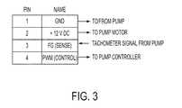
- FIG. 3shows a representative pin-out for a fan header operatively coupled to a pump
- FIG. 4shows a portion of but one of many leak detector embodiments disclosed herein;
- FIG. 5shows a block diagram of a leak detector and a portion of an associated control system in relation to a fluid heat exchange system
- FIG. 6shows a schematic illustration of an embodiment of a circuit configured according to the block diagram shown in FIG. 5 ;
- FIG. 7shows a pinout of a fan header operatively coupled to an embodiment of a leak detector disclosed herein;
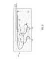
- FIG. 8shows a schematic illustration of a system including a leak detector disclosed herein.
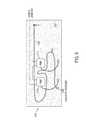
- FIG. 9shows a schematic illustration of an alternative system including a leak detector disclosed herein;
- FIG. 10shows a schematic illustration of a cooling system having an optical flow-rate sensor of the type disclosed herein;
- FIG. 11shows a schematic illustration of an optical flow-rate sensor
- FIG. 12shows a schematic illustration of a retainer suitable for the optical flow-rate sensor shown in FIG. 11 :
- FIG. 13shows one possible configuration of a rotational member as disclosed herein
- FIG. 14shows a schematic illustration of an apparatus configured to calibrate a flow-rate sensor of the type shown in FIG. 13 ;
- FIG. 15shows a plot of a calibration of a flow-rate sensor
- FIGS. 16A and 16Bshow respective schematic illustrations of a rotational member of the type shown in FIG. 13 ; in FIG. 16A , a reflector is shown; in FIG. 16B , the rotational member has rotated to a position obscuring the reflector shown in FIG. 16A from view;
- FIG. 17shows a selected proxy relationship (or correlation) between an observed flow rate of a working fluid (or indicia thereof) and a fan speed indicated by a simulated fan-tachometer signal;
- FIG. 18shows a block diagram of a computing environment suitable for use in combination with systems, methods and apparatus described herein.
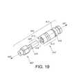
- FIG. 19illustrates a coupler of the type disclosed herein.
- FIG. 20contains a photograph of a working embodiment of a cooling system having automatically decoupleable couplers of the type shown in FIG. 19 .
- FIG. 21shows a branch of a fluid circuit of a heat transfer system.
- control systems, sensors, leak detectors, flow-rate sensors, decoupleable couplers, actuators, and associated circuits, computing environments, firmware and/or software having attributes that are different from those specific examples discussed hereincan embody one or more of the innovative principles, and can be used in applications not described herein in detail, for example, to detect a leak of a fluid (e.g., a liquid, a gas, or a saturated mixture thereof) from, or to observe a local speed of a flow of such a fluid through, a heat-transfer system having any of a variety of flow configurations, such as a contained flow within a fluid conduit or a free-stream flow (e.g., a region of a fluid flow sufficiently spaced from a fluid boundary as not to be influenced by the boundary).
- a fluide.g., a liquid, a gas, or a saturated mixture thereof
- a heat-transfer systemhaving any of a variety of flow configurations, such as a contained flow within a fluid conduit or a
- Such systemscan be configured to transfer heat to or from laser components, light-emitting diodes, chemical reactants undergoing a chemical reaction, photovoltaic cells, solar collectors, power electronic components, electronic components other than microprocessors, photonic integrated circuits, and other electronic modules, as well as a variety of other industrial, military and consumer systems now known or hereafter developed. Accordingly, embodiments of detectors and related control systems not described herein in detail also fall within the scope of this disclosure, as will be appreciated by those of ordinary skill in the art following a review of this disclosure.
- control systemsestimate or observe an attribute of a given system under control of the control system.
- a control systemcan provide an output corresponding to the estimated or observed attribute in order to achieve a desired system response.
- Controls systems (or portions thereof) disclosed hereincan be implemented in a computing environment. As indicated above and explained more fully below, some disclosed systems are configured to detect a leak of a working fluid from, for example, a liquid-based heat-transfer system. Some disclosed systems are configured to transmit an alert or other command in response to a detected leak.
- Some disclosed sensorsare configured to be backward compatible with existing control systems.
- some existing control systemsconfigured to monitor an operational status of a cooling fan for a computer system are configured to emit a signal corresponding to observed fan speeds, or to issue an alert or other command, when an observed fan speed drops below a selected threshold.
- some disclosed sensorshave a circuit configured to emit a first simulated tachometer signal corresponding to a first observed condition (e.g., similar to a tachometer signal emitted by a normally operating fan) and to emit a different simulated tachometer signal corresponding to a second observed condition.
- the different signal emitted in response to the second observed conditioncan be similar to a tachometer signal emitted by a failed or failing fan (e.g., a fan operating at an unacceptably low fan speed, or a fan having a locked rotor).
- An operational statusincludes a flow rate through a conduit.
- Some disclosed sensorsemit a simulated fan tachometer signal in correspondence with an observed volumetric (or mass) flow rate (or indicia thereof, such as, for example, a rotational speed of a rotational member within the flow of fluid).
- An operational statuscan reflect a presence or absence of a detected leak.
- Some disclosed leak detectorshave a circuit configured to emit a simulated tachometer signal similar to a tachometer signal emitted by a normally operating fan when no leak is detected and to emit a different signal (or no signal) in response to a detected leak.
- the different signal emitted in response to a detected leakcan be similar to a tachometer signal emitted by a failed or failing fan (e.g., a fan operating at an unacceptably low fan speed, or a fan having a locked rotor).
- Some disclosed systemsincorporate a sensor configured to detect or observe an indicia of a change in state of a heat-transfer system. Some indicia pertain to a rate of flow of a working fluid, for example, through a portion of a liquid-based heat-transfer system. Other indicia pertain to a leak of such a working fluid. Some disclosed systems are configured to transmit an alert or other command in response to a threshold condition observed or detected by such a sensor.
- some disclosed flow-rate sensorsare configured to observe (or to detect) a frequency at which a rotational member rotates about a selected axis of rotation in response to a passing flow of a working fluid.
- a rotational frequencycan correspond to a speed (and thus a rate of flow) at which a flow of a selected fluid passes by or over the rotational member.
- computer systemscommonly include one or more axial fans for cooling an electronic component.
- a rate of heat transfer from an electronic component or from a liquid-to-air heat exchanger (e.g., a radiator) to a stream of air passing over the component or the heat exchangergenerally corresponds, in part, to a speed of the air stream.
- a speed of such an air streamgenerally corresponds to a rotational speed of the fan.
- some computer systemsinclude a control system configured to adjust a fan speed in response to an observed temperature (e.g., a temperature of an electronic component).
- some control systemsare configured to modulate a duty cycle of, for example, a square wave, and some fans, in turn, are configured to adjust their fan speed in correspondence with the modulated duty cycle.
- some computer systemsinclude a control system configured to observe an output signal from a fan.
- Such an output signalcan correspond to a rotational speed of the fan.
- a fancan include a Hall cell configured to emit a square wave having a frequency corresponding to a rotational speed of a rotating magnetic field generated by a rotating fan rotor.
- Such an emitted square wavecan have a duty cycle of about 50% when the rotor rotates at an approximately constant speed. Since the frequency of the square wave can correspond to the rotational speed of the fan, such a square wave is sometimes referred to as a “tachometer signal.”
- FIG. 1illustrates one pulse from a typical tachometer output having a square wave waveform.
- FIG. 1illustrates one pulse from a typical tachometer output having a square wave waveform.
- FIG. 1illustrates one pulse from a typical tachometer output having a square wave waveform.
- FIG. 1illustrates one pulse from a typical tachometer output having a square wave waveform
- FIG. 2shows a representative waveform of a tachometer output for a fan that changes from an operating state (“Running”) having a 50% duty cycle, to a “Locked rotor” state in which no tachometer signal (or a steady-state signal) is emitted because the fan rotor does not rotate, and back to an operating state (“Running”) having a 50% duty cycle.
- a control systemcan be configured to transmit an alert or other command in response to an observed signal exceeding a selected upper threshold or falling below a selected lower threshold. Some control systems are configured to resume monitoring the observed signal after transmitting the alert or other command. Other control systems (sometimes referred to in the art as a “latching system”) are configured to continuously transmit an alert or other command.
- Some existing control systemsare configured to observe a tachometer signal emitted by a rotating fan and to emit a signal or otherwise initiate a system command (e.g., send an “alert”, or initiate a system shut-down) in response to a selected change in state of a tachometer signal.
- a selected change of state of a tachometer signalcan include a drop in frequency below a selected threshold (e.g., corresponding to an unacceptably low fan speed), a cessation of a tachometer signal or an emission of steady-state tachometer signal, as when a fan rotor stops rotating.
- a control systemcan be configured to emit a signal or otherwise initiate a system command if an observed signal indicates that a fan is in a “locked rotor” state.
- IPMIIntelligent Platform Management Initiative
- An IPMI subsystemcan operate independently of an operating system of a computer incorporating the IPMI subsystem, allowing a system administrator to manage the computer independently of the operating system (e.g., before the operating system boots, or when the computer is powered down).
- a Baseboard Management Controllercan include a specialized microcontroller configured to manage an interface between the system management software and computer system hardware.
- an IPMI subsystemcan monitor a status of various operating parameters, including, for example, system temperatures, fan speeds, chassis intrusion, etc.
- an IPMI subsystemcan be configured to monitor a tachometer signal emitted by one or more fans and, when the tachometer signal indicates a fan speed below a selected threshold, the subsystem can emit an alert or other command.
- Computer systems incorporating such control systems for fanscommonly include a plurality of electrical connectors, with each being configured to operatively couple a fan to a corresponding plurality of circuits configured, respectively, to power, control and monitor the fan.
- an electrical connectorcan have four electrical couplers corresponding respectively to (A) a power supply circuit configured to convey an electrical current for powering the fan motor; (B) an electrical ground; (C) a pulse-width modulation circuit configured to convey a pulse-width modulation signal (sometimes referred to as a “PWM signal”) for controlling the fan; and (D) a sense circuit configured to convey a tachometer signal corresponding to a fan speed (sometimes referred to in the art more generally as a frequency generator signal, or an “FG” signal).
- Such an electrical connectoris sometimes referred to in the art as a “header” or a “fan header”.
- FIG. 3shows a typical pinout for a header with annotations reflecting use of the header in conjunction with a pump.
- a leak detector circuitcan be configured to respond to a leak (e.g., moisture or another selected proxy for a leak) of a working fluid detected by a sensor.
- a leake.g., moisture or another selected proxy for a leak
- an innovative leak detector circuitcan be configured to emit a first waveform in the absence of a detected leak and to emit a second waveform responsive to a detected leak.
- Any suitable sensor configured to detect a leak (or other proxy for a leak, e.g., moisture, presence of a working fluid at a position external to a heat-transfer system, a low pressure in the heat-transfer system, a low fluid level in the heat-transfer system)can be used in connection with such an electrical circuit.
- a leak-detection sensor 5can have a first leak-detection wire 10 and a second leak-detection wire 20 , as shown in FIG. 4 .
- the first and the second leak-detection wires 10 , 20can comprise respective exposed traces on a printed circuit board.
- the first leak-detection wire 10can extend from a power plane, V 1 .
- the second leak-detection wire 20can extend generally parallel to and spaced apart from the first leak-detection wire 10 .
- a region in which the first and the second wires 10 , 20 are coextensivecan define a leak-sensitive region 25 of the sensor.
- a leakcan be detected when an open circuit between the first and the second leak-detection wires 10 , 20 is closed.
- a drop 30 of a leaked liquidcan span a gap between the first and the second leak-detection wires 10 , 20 within the leak-sensitive region 25 of the sensor 5 , electrically coupling the first and the second leak-detection wires to each other.
- the circuit of the leak detector 5can emit a corresponding signal indicative of a detected leak.
- the second leak-detection wire 20can be pulled high (e.g., can have a voltage potential corresponding to the voltage of the power plane, V 1 ), and can activate a relay 35 .
- the latch 40electrically coupling the pump and the fan header to each other can be switched to open (e.g., disconnect) the coupling between the pump and the fan header.
- Such a disconnection of at least one coupling between the pump and the headercan serve as a signal to a monitoring system that a leak has been detected.
- the monitoring systemcan in response initiate an alert or a system command.
- a relaycan close a circuit to activate an electro-mechanical actuator of the type described herein, e.g., to physically disconnect or to otherwise isolate a branch of a fluid circuit of a heat-transfer system.
- a leak detection sensoris schematically illustrated as extending from an integrated pump and heat exchanger assembly (sometimes referred to in the art as a “Head Module”).
- Head Modulean integrated pump and heat exchanger assembly
- the leak detection sensor 125 , 125 a shown in FIG. 5has first and second leak-detection wires 110 , 120 (referred to in FIG. 6 as “Cable Conductor 1 ” and “Cable Conductor 2 ”, respectively) spaced apart from each other to form a gap 121 .
- leak detection sensoris sometimes referred to in the art as a “Leak Detect Cable.”
- One or both of the leak-detection wires 110 , 120can be partially or fully embedded (or otherwise surrounded by) a semi-conducting carrier.
- the first and/or the second leak-detection wires 110 , 120can be formed from an alloy of copper.
- a conductive fluid spanning the gap between the first and second leak-detection wires 110 , 120can provide a “non-trivial” resistance between the first and the second leak-detection wires.
- a “non-trivial resistance”means a finite resistance sufficient to electrically couple the first and the second leak-detection wires to each other.
- a non-trivial resistance between the first and the second leak-detection wirescan supply the analog Leak Sense line 122 with a non-zero voltage.
- some leak detectorshave a functional module 130 (sometimes referred to in the art as a “Glue Module”) configured to respond to a leak detected by a leak detection sensor 125 .
- the Glue Module shown in FIG. 5can be configured to deliver a logic high signal to the FG line (labeled as “Output Tach” in FIG. 5 ) responsive to a signal indicative of a leak received over the Leak Sense line 122 .
- the Glue Logic moduleis configured to monitor the Leak Sense line 122 continuously. In other embodiments, the Glue Logic module is configured to sample the Leak Sense line 122 at defined times (e.g., at selected intervals, or at selected intermittent times). The Glue Logic can also be configured to transmit a signal over an Enable Detect line 123 , and, as shown by way of example in FIG. 6 , the Leak Detection Circuit 125 a can be configured to become operative in response to a signal received over the Enable Detect line 123 .
- a Glue Logic modulecan be configured to interrupt operation of a pump motor responsive to a signal received over the Leak Sense line 122 indicative of the existence of a leak (e.g., an electrical coupling between the first and the second leak-detection wires).
- a Motor Cutoff line 126can carry a signal emitted by the Glue Logic, and a Motor Control Circuit 127 can respond to a signal received over the Motor Cutoff line 126 by interrupting power to the motor 128 .
- the Glue Logiccan force an output tachometer signal 129 (e.g., an FG signal) from the Head Module to a logic 0 (e.g., low logic) to signify to a monitoring system that there has been a failure associated with the Head Module.
- an output tachometer signal 129e.g., an FG signal
- a logic 0e.g., low logic
- leak-detection sensor and leak detector circuit configurationsare possible.
- such sensorscan include a capacitive moisture sensor, an optical sensor, an infrared sensor, a pressure sensor configured to observe a pressure within the heat-transfer system, a sensor configured to detect a low fluid level in the heat-transfer system, and other sensors now known and hereafter developed.
- Some leak detectorscan have an electrical circuit operatively coupled to an FG signal pin of a header and be configured, in the absence of a detected leak, to emit a simulated tachometer signal 129 having a waveform similar to a waveform emitted by a properly operating fan.
- FIG. 7shows a header operatively coupled to such an electrical circuit.
- the electrical circuit(not shown) can be further configured to emit a simulated tachometer signal 129 having a waveform similar to a failed or failing fan in response to a detected leak of a liquid from a liquid-base heat-transfer system (e.g., when a circuit between first and second leak-detection wires is closed).
- the electrical circuitcan be configured to emit no tachometer signal, similar to a fan having a locked rotor (see FIG. 2 ) in response to a detected leak of a liquid from a liquid-based heat-transfer system.
- a leak detector circuit 225can be operatively coupled to an available fan header.
- the simulated signalcan be interpreted as by switching a relay as described above in relation to FIG. 4 .
- a leak-detection sensor 225can be operatively coupled to an electrical circuit associated with one or more pumps 210 of a liquid-based heat-transfer system.
- a pump 210can be electrically coupled to a header 231 having a power pin, a ground pin, a PWM pin and an FG pin.
- the power pincan be operatively coupled to the pump motor to convey an electrical current to the pump to operate the pump.
- the PWM pinbe operatively coupled to a pump controller and convey a pump-control signal to the pump controller, e.g., to control a speed of the pump.
- the FG pincan convey monitor a tachometer signal emitted by the pump to a sensing circuit configured to monitor the pump (or fan) speed.
- a leak detector circuit 225can be operatively coupled between the power pin of the header 231 and the pump motor 210 .
- the leak detector circuit 225can interrupt a supply of electrical current to the pump (or increase a supply of electrical current to the pump) in response to a detected leak, causing a corresponding reduction (or increase) in pump speed.
- a corresponding FG signal emitted by the pumpcan reflect the diminished (or increased) pump speed.
- a system configured to monitor the FG signal emitted by the pumpcan, in response to a reflected change in pump speed, transmit an alert signal (e.g., to a system administrator), a system command (e.g., a command to increase a pump speed of another pump in an attempt to compensate for a diminished performance of a stalled pump, a system-shut-down command, etc.), or both.
- an alert signale.g., to a system administrator
- a system commande.g., a command to increase a pump speed of another pump in an attempt to compensate for a diminished performance of a stalled pump, a system-shut-down command, etc.
- Some implementersmight elect not to interrupt power to a pump if stopping a pump might be considered a catastrophic failure.
- a leak detector circuit 225can be operatively coupled between the PWM pin of the fan header 231 and the pump 210 .
- the leak detector circuit 225can interrupt a PWM signal conveyed to the pump 210 by the PWM pin of the fan header and convey an alternative PWM signal (or no PWM signal) to the pump in response to a detected leak.
- the alternative PWM signalcan cause the pump to speed up, to slow down, or to stop.
- An FG signal emitted by the pumpcan reflect the change in pump speed.
- a system configured to monitor the FG signal emitted by the pumpcan, in response to a reflected change in pump speed, transmit an alert signal (e.g., to a system administrator), a system command (e.g., a command to increase a pump speed of another pump in an attempt to compensate for a diminished performance of a stalled pump, a system-shut-down command, etc.), or both.
- an alert signale.g., to a system administrator
- a system commande.g., a command to increase a pump speed of another pump in an attempt to compensate for a diminished performance of a stalled pump, a system-shut-down command, etc.
- a leak detector circuit 225can be operatively coupled between the FG pin of the fan header 231 and the pump 210 .
- the leak detector circuit 225can interrupt an FG signal emitted by the pump and convey an alternative FG signal (or no FG signal) to the FG signal pin in response to a detected leak.
- the alternative FG signalcan simulate a diminished pump speed, a selected increased pump speed, or no pump speed.
- a system configured to monitor the simulated FG signalcan, in response to a selected change in the simulated FG signal corresponding to a change in pump speed, transmit an alert signal (e.g., to a system administrator), a system command (e.g., a command to increase a pump speed of another pump in an attempt to compensate for a diminished performance of a stalled pump, a system-shut-down command, etc.), or both.
- an alert signale.g., to a system administrator
- a system commande.g., a command to increase a pump speed of another pump in an attempt to compensate for a diminished performance of a stalled pump, a system-shut-down command, etc.
- a leak sensor 225can be positioned adjacent to (e.g., routed around) a pump 210 or other component of a liquid-based heat-transfer system, as indicated by way of example in FIGS. 8 and 9 .
- a sensor 225can be positioned on, embedded in, affixed to, positioned adjacent to, or otherwise operatively coupled to a printed circuit board 205 such that the sensor defines a sensor region 226 .
- the sensor regioncan be selected to correspond to a region that might be susceptible to wetting by a working fluid in the event of a leak.
- FIGS. 8 and 9show examples of a sensitive region defined by a leak sensor 225 .
- the illustrated sensitive region 226extends along the leak sensor (e.g., between points “A” and “B”) routed on a surface of a printed circuit board 205 .
- the leak detectorcan be configured to interrupt a tachometer signal emitted by each pump 210 in response to a detected leak.
- each of the illustrated pumps 210 and the leak detector circuit 225can be configured to emit one or more simulated fan-tachometer signals corresponding to one or more respective observed operational states.
- the one or more simulated fan-tachometer signalscan be transmitted over the illustrated fan headers 231 , for example, to an IPMI bus.
- a controllercan receive and interpret the one or more signals as a proxy for the observed operational state, and responsively issue one or more corresponding system commands.
- the leak detector circuit 225 ′is configured to interrupt a simulated tachometer signal in response to a detected leak. Such interruptions can simulate a tachometer signal emitted by a fan having a “locked rotor.”
- a corresponding control systemconfigured to monitor a tachometer signal emitted from a fan can respond to a simulated “locked rotor” signal by initiating an alert or other system command.
- FIG. 10illustrates a fluid circuit 310 having a pump 320 , an optical flow-rate sensor 330 , a heat exchanger 340 configured to transfer heat 341 from a heat dissipating component (e.g., a microprocessor), and a radiator 350 configured to dissipate heat 351 from the working fluid to an environment 352 .
- a heat dissipating componente.g., a microprocessor
- the radiator 350configured to dissipate heat 351 from the working fluid to an environment 352 .
- the pump 320 and the heat exchanger 340are combined into an operative subassembly, as described by way of example in U.S. patent application Ser. No. 12/189,476, among other patent applications.
- a flow-rate sensor 330can include a rotational member 332 positioned within a segment of conduit 331 and a tachometer 334 configured to detect a rotational speed of the rotational member. As shown schematically in FIG. 11 , the rotational member 332 can be configured to receive momentum from a flow of a working fluid passing over the rotational member, in a manner similar as a turbine of a windmill receiving momentum from a flow of air passing over the turbine.
- a rotational member 332 of the type disclosed hereincan include a generally axisymmetric arrangement of wings, foils, blades, faces, or screws positioned within a conduit suitable for conveying a flow of a working fluid such that a flow of a selected fluid passing over the arrangement of wings, foils, blades, faces, or screws applies a torsional force to the rotational member to urge the rotational member in rotation about the axis of rotation.
- Some body portionscomprise a thin shell member having opposed first and second sides 337 a , 337 b .
- a thin shell membercan define a primary axis 338 extending longitudinally of the shell member and a secondary axis 338 a extending transversely relative to the primary axis.
- the thin shell membercan be twisted about the primary axis 338 so as to define a foil-shaped member configured to convert momentum from a passing fluid to a torsional force applied to the thin shell member.
- FIG. 13shows but one possible example of such a foil-shaped member.
- a torsional force applied to the rotational membercan correspond to a rate of flow of a working fluid past the rotational member, with higher flow rates corresponding to relatively higher torsional forces.
- a lift force on a wing in a stream of an incompressible fluidcan increase in proportion to the square of the speed of the approaching fluid.
- a lift force applied to the rotational member 332 at a position spaced apart from a central, longitudinal axis 338applies a turning moment (e.g., a torque, or a torsional force) to the rotational member about the axis 338 .
- the turning momentcan urge the rotational member 32 in rotation.
- the turning momentcan urge the rotational member 332 in rotation about the central, longitudinal axis 338 .
- the turning momentcan correspond to the lift force (torsional force) generated by the flow of the working fluid past the rotational member.
- the speed of rotation of the rotational member 332can correspond to the torsional force applied to the rotational member.
- the rotational speed of the rotational membercan correspond to the speed of an approaching flow of the fluid.
- a volumetric flow rate (or a mass flow rate) of the fluid through a closed conduitcorresponds to the speed of the fluid through the conduit.
- a rotational speed of the rotational member 332 positioned within a fluid conduitcan correspond to a volumetric flow rate (or mass flow rate) of a fluid through the conduit 331 .
- determining an algebraic expression for a relationship between rotational speed of a given rotational member in a flow of a selected fluidmight be possible, such a relationship or correlation can be determined experimentally for each combination of rotational member configuration, conduit configuration, and working fluid.
- the plot in FIG. 15generally illustrates one example of a correlation between an observed rotational speed of the rotational member 332 and a (volumetric or mass) flow-rate past the rotational member.
- An apparatus of the type shown in FIG. 14can be used to assess such a correlation and to generate such a plot.
- a conventional flow-rate sensore.g., a Venturi-type sensor
- the tachometercan emit a signal indicative of the rotational speed of the rotational member at each respective flow rate.
- Each flow-rate/rotational speed pair of readingscan be plotted as indicated by the plot shown in FIG. 15 , to reveal an experimentally determined correlation between rotational speed of the rotational member 332 and fluid flow rate through the conduit, for a particular combination of rotational member configuration, conduit configuration, and working fluid.
- a unique correlation between rotational speed of the rotational member and flow rate of working fluidexists for each combination of working fluid, rotational member configuration, and conduit configuration.
- the rotational speed of the rotational membercan be observed, and, based on the correlation of flow-rate through the conduit segment 332 and rotational speed of the rotational member, the corresponding flow rate (e.g., volumetric or mass flow rate) can be determined.
- the tachometercan include any of a variety of known and hereafter developed sensor arrangements suitable to detect a rotational speed of the rotational member 331 .
- a suitable tachometercan include an optical sensor having an emitter, a detector, and a counter.
- the rotational member 332can be positioned in a conduit 331 having a transparent outer wall 331 a , or other suitable port configured to permit a selected frequency range (or band) of electromagnetic radiation (e.g., radiofrequency, X-rays, or light in the infrared, visible, or ultraviolet spectra) to pass therethrough.
- a selected frequency rangeor band
- electromagnetic radiatione.g., radiofrequency, X-rays, or light in the infrared, visible, or ultraviolet spectra
- the following discussionwill refer to the emitter as a light emitter and the detector as a light detector by way of example, and not limitation, for ease of description.
- a light emitter 333can emit light (e.g., for a duration substantially longer than a period of rotation for the rotational member 332 ) in a direction toward the rotational member 332 , and one or more portions 335 of the rotational member can reflect incident light (or other radiation band) from the emitter 333 toward the light detector 336 .
- the counter 337can increment a count each time the light detector 336 detects light reflected by the reflective portion 335 of the rotational member 332 .
- Such detectioncan be responsive to a detected presence of light compared to a detected absence of light, or to a detected absence of light compared to a detected presence of light.
- a rate at which the count increasescan correspond to a rate at which the light detector 336 detects a reflection of light from the rotational member 332 .
- the rate at which the light detector 336 detects a reflection of light from the rotational member 332can correspond to a rotational speed (i.e., a frequency of rotation, or an angular speed) of the rotational member 332 , and thus, as noted above, a rate of flow of a working fluid through a selected conduit.
- the rotational member 332can be configured to reflect incident light toward the detector 336 once per revolution of the rotational member about the axis of rotation, as with the member 332 shown in FIGS. 13, 16A and 16B .
- the rotational member 332can have a relatively less reflective body portion 337 a , 337 b that rotates about an axis of rotation 338 and a relatively more reflective reflector portion 335 affixed to or on, or integral with, the relatively less reflective body portion 337 a , 337 b .
- the reflector portion 335can be so arranged as to reflect light toward the detector 336 once during each revolution of the body portion 332 .
- the reflector portion 335can comprise a reflector member positioned on one of the opposed sides 337 a , 337 b of the thin shell member shown in FIGS. 13, 16A and 16B .
- a rate (or a frequency) at which the count increments in response to detected reflections from the reflector portion 335can approximate the angular speed of the rotational member, which in turn can correspond to a rate of flow of a working fluid through the conduit 331 .
- the rotational member 332can be configured to reflect incident light toward the detector 336 twice per revolution of the rotational member about the axis of rotation.
- the rotational member 332can comprise opposed first and second reflective portions (not shown) so arranged relative to the opposed faces 337 a , 337 b that each of the first and the second reflective portions reflects light toward the detector 36 once during each revolution of the rotational member (i.e., such that light is reflected toward the detector 36 twice per revolution of the rotational member).
- one-half of a rate (or a frequency) at which the count increments in response to detected reflections from the first and the second reflector portionscan approximate the angular speed of the rotational member, which in turn can correspond to a rate of flow through the conduit.
- the rotational member 332can be configured to reflect incident light toward the detector N times per revolution of the rotational member about the axis of rotation.
- 1/N of a rate (or a frequency) at which the count increments in response to detected reflections from the rotational membercan approximate the angular speed of the rotational member, which in turn can correspond to a rate of flow through the conduit.
- FIG. 12shows a particular exemplary embodiment of a flow-rate sensor 330 of the type described above.
- the illustrated sensor 330has a transparent (in relation to a selected spectrum of incident electromagnetic radiation) segment 336 of conduit with a rotational member 332 positioned therein.
- a tachometer 334is positioned externally of the conduit and is arranged to emit light (or other band of radiation) through the transparent segment 36 and toward the rotational member 332 .
- the tachometer 334is further arranged to detect light (or other radiation) reflected by the rotational member 332 through the transparent segment 336 .
- the illustrated sensor 330also has a retainer 360 configured to suspend the rotational member 332 within the conduit 31 in spaced relation from an interior wall 331 b of the transparent segment of conduit. Such a suspended arrangement can permit the rotational member 332 to rotate about a selected axis of rotation 338 within the conduit 331 and without being carried away by a flow of a working fluid passing through the conduit.
- the retainer 360can include an upstream retainer member 361 and a downstream retainer member 362 .
- One or both of the retainer members 361 , 362can be configured to urge outwardly against an inner wall 331 b of the segment 331 a of conduit.
- one or both retainer members 361 , 362comprise an elongate member that resiliently urges against the wall 331 b , as shown in FIG. 12 .
- one or both retainer members 361 , 362include a segment 363 configured to matingly engage with a correspondingly configured region of the inner wall 331 b of the conduit 331 a .
- the segment 363 configured to matingly engage with the inner wall 331 bcan include a bent segment 364 of wire configured to rest within a corresponding détente 365 , or other recessed region of the inner wall 331 b.
- the rotational member 332can be rotatably coupled to the retainer 360 .
- a first swivel member 366 acan rotatably couple the rotational member 35 to an upstream retainer member 361 and a second swivel member 366 b can rotatably couple the rotational member 335 to a downstream retainer member 362 , as shown in FIG. 11 .
- the conduit 331 a having a rotational member 32 positioned thereincan be fluidly coupled in series (or “in-line”) with one or more other components of a fluid circuit 310 .
- Such a placement of the conduit 331 acan facilitate measurement of a rate of flow of a working fluid through the one or more components, once a correlation (e.g., FIG. 15 ) between observed rotational speed of the rotational member 332 and a volumetric (or mass) flow rate of the working fluid through the conduit 331 a has been determined.
- a flow sensor 330 of the type described hereincan be incorporated in a cooling system, such as, for example, a cooling system configured to cool an electronic component or other device that dissipates waste heat during operation.
- a tachometer output of such a flow sensorcan indicate a rate of fluid flow through the sensor.
- the output of the tachometer 334can be multiplexed so as to be compatible with a known or installed communication bus, e.g., over an IPMI bus.
- a computer system incorporating a cooling systemcan include a controller configured to transmit an alert or other command in response to an observed signal exceeding a selected upper threshold or falling below a selected lower threshold.
- the observed signalcan be emitted by a flow sensor.
- the emitted signalcan be emitted by a tachometer 334 configured to observe a rotational speed of a rotational member 332 , and the control system can transmit an alert or other command in response to an observed tachometer signal exceeding a selected upper threshold or falling below a selected lower threshold.
- the upper or lower thresholdcan correspond to an upper or a lower fluid flow-rate threshold.
- a flow-rate sensore.g., an optical flow-rate sensor 330 of the type described herein, can emit a simulated fan-tachometer signal in correspondence with an observed flow rate (or indicia thereof). For example, until a lower threshold flow rate (or indicia thereof) is observed by the flow-rate sensor, the sensor can emit a simulated fan-tachometer signal indicative of a given condition of a fan, for example, a stalled fan rotor. Between the lower threshold flow rate (or indicia thereof) and a selected upper threshold observed flow rate (or indicia thereof), the sensor can emit a corresponding simulated fan-tachometer signal indicative of a selected fan speed.
- a correlationcan be defined between simulated fan-tachometer speed and observed flow rate (or indicia thereof) between selected upper and lower threshold flow rates (or indicia thereof), as shown in FIG. 17 .
- the sensor 330can emit a simulated fan-tachometer signal correlated to (or encoding) a flow rate (or indicia thereof) observed by the sensor.
- the simulated fan-tachometer signalcan be conveyed over a known bus using known protocols (e.g., an IPMI bus) and observed by a control system.
- the control systemin turn, can decode the simulated fan-tachometer signal using the known correlation ( FIG. 17 ) between observed flow rate (or indicia thereof) and simulated fan speed.
- Some flow-rate sensorscan have an electrical circuit operatively coupled to an FG signal pin of a header and be configured to emit a simulated tachometer signal having a waveform similar to a waveform emitted by an operating (or stalled) fan.
- the electrical circuit(not shown) can be further configured to emit a simulated tachometer signal having a waveform similar to a failed or failing fan in response to an observed flow rate (or indicia thereof) below a selected lower threshold.
- a flow-rate sensorcan be operatively coupled to a control system associated with one or more pumps of the liquid-based heat-transfer system.
- the control systemcan emit a control signal for adjusting operation of one or more pumps in the fluid circuit (e.g., a cooling system) responsively to an observed proxy (or other) signal emitted by a flow-rate sensor.
- the control systemcan emit a control signal.
- a control signalcan cause a given one or more pump to increase speed, can cause a supplemental pump to become operational, and/or can cause a valve to open (or close), to increase flow rate through a desired portion of a cooling system.
- Such a control signalcan alter an operational state of a computer system.
- the computer systemcan reduce or limit workload of a subsystem at risk of overheating (e.g., microprocessor workload can be limited or reduced, read/write traffic across a memory bus can be limited or reduced) absent increased cooling.
- a subsystem at risk of overheatinge.g., microprocessor workload can be limited or reduced, read/write traffic across a memory bus can be limited or reduced
- the control systemcan emit a control signal.
- a control signalcan cause a given one or more pumps to decrease speed (e.g., to save power and/or lower acoustic emissions by the pump), cause a supplemental pump to slow down or to stop operating, and/or cause a valve to open (or close), decreasing flow rate through a portion of a cooling system to a suitable level.
- a sensor circuitcan be configured to emit a proxy signal corresponding to an observed operational state.
- Each in a plurality of discrete proxy signalscan correspond to each respective observed operational state in a plurality of observable operational states.
- such a proxy signalcan be a simulated fan-tachometer signal.
- Each discrete simulated fan-tachometer signalcan correspond to a respective observed operational state.
- a simulated fan-tachometer signal corresponding to a fan speed of 200 RPMcan constitute a proxy for a selected observed flow rate (or indicia thereof, such as, for example, a rate of increasing count of detected reflections from a reflective portion 35 of a rotational member 32 ).
- a simulated fan-tachometer signal corresponding to a different fan speede.g., 250 RPM
- a simulated fan-tachometer signal corresponding to a fan speed of 200 RPMcan constitute a proxy for an observed first flow rate at a location within the system and a simulated fan-tachometer signal corresponding to a fan speed of 250 RPM can constitute a proxy for an observed second (e.g., different) flow rate.
- FIG. 17shows an example, pre-defined correlation between simulated fan-tachometer signal and flow rate.
- a simulated fan-tachometer signal corresponding to a fan speed of 200 RPMcan constitute a proxy for an observed leak at a first location within the system and a simulated fan-tachometer signal corresponding to a fan speed of 250 RPM can constitute a proxy for an observed leak at a second (e.g., different) location within the system.
- proxy signalscan be transmitted over and observed from, for example, the IPMI bus.
- a controller operatively coupled to the IPMI buscan observe the proxy signal, interpret the observed proxy signal, as by comparison to a lookup table, and, if appropriate, issue one or more selected system commands responsively to the observed or interpreted proxy signal.
- proxy signal valuesBy way of illustrate of disclosed principles, the following table summarizes specific examples of proxy signals, proxy signal values and corresponding operational states represented by the proxy signal values:
- FIG. 18illustrates a generalized example of a suitable computing environment 400 in which described methods, embodiments, techniques, and technologies relating, for example, to detection and/or removal of unwanted noise signals from an observed signal can be implemented.
- the computing environment 1100is not intended to suggest any limitation as to scope of use or functionality of the technologies disclosed herein, as each technology may be implemented in diverse general-purpose or special-purpose computing environments.
- each disclosed technologymay be implemented with other computer system configurations, including wearable and handheld devices (e.g., a mobile-communications device, or, more particularly but not exclusively, IPHONE®/IPAD® devices, available from Apple Inc.
- multiprocessor systemsmultiprocessor systems, microprocessor-based or programmable consumer electronics, embedded platforms, network computers, minicomputers, mainframe computers, smartphones, tablet computers, data centers, and the like.
- Each disclosed technologymay also be practiced in distributed computing environments where tasks are performed by remote processing devices that are linked through a communications connection or network.
- program modulesmay be located in both local and remote memory storage devices.
- the computing environment 1100includes at least one central processing unit 1110 and memory 1120 .
- the central processing unit 1110executes computer-executable instructions and may be a real or a virtual processor. In a multi-processing system, multiple processing units execute computer-executable instructions to increase processing power and as such, multiple processors can run simultaneously.
- the memory 1120may be volatile memory (e.g., registers, cache, RAM), non-volatile memory (e.g., ROM, EEPROM, flash memory, etc.), or some combination of the two.
- the memory 1120stores software 1180 a that can, for example, implement one or more of the innovative technologies described herein, when executed by a processor.
- a computing environmentmay have additional features.
- the computing environment 1100includes storage 1140 , one or more input devices 1150 , one or more output devices 1160 , and one or more communication connections 1170 .
- An interconnection mechanismsuch as a bus, a controller, or a network, interconnects the components of the computing environment 1100 .
- operating system softwareprovides an operating environment for other software executing in the computing environment 1100 , and coordinates activities of the components of the computing environment 1100 .
- the store 1140may be removable or non-removable, and can include selected forms of machine-readable media.
- machine-readable mediaincludes magnetic disks, magnetic tapes or cassettes, non-volatile solid-state memory, CD-ROMs, CD-RWs, DVDs, magnetic tape, optical data storage devices, and carrier waves, or any other machine-readable medium which can be used to store information and which can be accessed within the computing environment 1100 .
- the storage 1140stores instructions for the software 1180 b , which can implement technologies described herein.
- the store 1140can also be distributed over a network so that software instructions are stored and executed in a distributed fashion. In other embodiments, some of these operations might be performed by specific hardware components that contain hardwired logic. Those operations might alternatively be performed by any combination of programmed data processing components and fixed hardwired circuit components.
- the input device(s) 1150may be a touch input device, such as a keyboard, keypad, mouse, pen, touchscreen, touch pad, or trackball, a voice input device, a scanning device, or another device, that provides input to the computing environment 1100 .
- the input device(s) 1150may include a microphone or other transducer (e.g., a sound card or similar device that accepts audio input in analog or digital form), or a computer-readable media reader that provides audio samples to the computing environment 1100 .
- the output device(s) 1160may be a display, printer, speaker transducer, DVD-writer, or another device that provides output from the computing environment 1100 .
- the communication connection(s) 1170enable communication over a communication medium (e.g., a connecting network) to another computing entity.
- the communication mediumconveys information such as computer-executable instructions, compressed graphics information, processed signal information (including processed audio signals), or other data in a modulated data signal.
- disclosed computing environmentsare suitable for transforming a signal corrected as disclosed herein into a human-perceivable form.
- disclosed computing environmentsare suitable for transforming a signal corrected as disclosed herein into a modulated signal and conveying the modulated signal over a communication connection
- Machine-readable mediaare any available media that can be accessed within a computing environment 1100 .
- machine-readable mediainclude memory 1120 , storage 1140 , communication media (not shown), and combinations of any of the above.
- Tangible machine-readable (or computer-readable) mediaexclude transitory signals.
- FIG. 19shows a photograph of one embodiment of a two-member coupler.
- the fluid coupler 400has a first member 410 configured to matingly couple with and to decouple from a second member 420 to provide a decoupleable coupling between a corresponding first fluid conduit 401 and a corresponding second fluid conduit 402 .
- Such a couplingis depicted, for example, schematically at inlets 150 a - n and outlets 140 a - n in FIG. 6 in U.S. patent application Ser. No. 13/559,340.
- one or both of the members 410 , 420can have an internal valve that automatically closes before, during or after the members 410 , 420 are decoupled from each other and automatically opens before, during or after the members are coupled to each other.
- a first member 410can define an open interior bore 413 sized to receive a shank 422 extending from the second member 420 .
- Either or both members 410 , 420can define an interior valve that opens after the bore 413 matingly and/or sealingly engages the shank 422 .
- an interior wall of the bore 413can have a pliable gasket (e.g., an O-ring) extending circumferentially around the bore and positioned at a selected first depth within the bore.
- the gasketcan be configured relative to the shank (e.g., a diameter thereof) to sealingly engage with an outer surface of the shank 422 as the shank slides into the bore 413 to a depth greater than the selected first depth.
- a portion within the bore 413can urge against a portion of the shank to open either or both valves corresponding to the respective members 410 , 420 and thereby to fluidically couple the first conduit 401 with the second conduit 402 .
- Such automatic actuation of the valvescan result from a resiliently compressible member (e.g., a spring, not shown).
- a resiliently compressible membere.g., a spring, not shown
- the valvecan be closed in an “at-rest” position when urged by a corresponding resiliently compressible member.
- the coupling members 410 , 420can define correspondingly configured features that urge the valve open against the force applied by the resiliently compressible member as the members 410 , 420 are brought into a mating engagement.
- the coupler members 410 , 420can inhibit fluid leaks when coupling or decoupling the coupler members 410 , 420 .
- a compressive force applied between the members 410 , 420 that actuates the valve by overcoming a force of a resilient member, as just described,can compress such a resilient member.
- the compressed resilient membercan urge the members 410 , 420 apart from each other when the compressive force is removed.
- the coupler 400can also have a retainer configured to retain the decoupleable coupling between the first member 410 and the second member 420 against the outwardly applied force of the compressed resilient member.
- the compressed resilient membercan urge the first member 410 and the second member 420 apart with sufficient force as to cause the coupled members 410 , 420 to decouple from each other and thereby to automatically close the respective valves.
- the retainer depicted in FIG. 19includes a cylindrical sleeve 414 overlying a body 412 of the first member 410 , a plurality of bearings positioned at discrete circumferential positions relative to the bore 413 , as well as a groove 424 positioned proximally of the shank 422 of the second member 420 .
- the bearings 418rest within the groove 424 .
- the wall of the grooveurges against the bearings when the mated first and the second members 410 , 420 are urged together in compression or pulled apart in tension, and the sleeve 414 overlying the bearings prevents the bearings 418 from moving radially outward from the bore 413 , locking the first and the second members 41 , 420 together.
- the sleeve 414can slide longitudinally to and fro relative to the body 412 from a retention configuration, as shown in FIG. 19 to an engagement/disengagement configuration (not shown).
- the sleeve 414longitudinally retracts from the depicted retention configuration until the sleeve urges against a shoulder 416 defined by the body 412 .
- the bearings 418can move radially outward relative to the bore 413 , allowing the members 410 , 420 to separate from each other as they are pulled apart.
- the illustrated sleevedefines an outer surface and a circumferentially extending groove recessed from the outer surface.
- the coupler member 410includes a resilient member (e.g., a spring, not shown) configured to resiliently urge the sleeve 414 toward the retention configuration shown in FIG. 19 .
- a resilient membere.g., a spring, not shown
- the force of the resilient spring and any friction as between the sleeve and the body 412needs to be overcome.
- the resilient memberurges the sleeve 414 toward the retention configuration.
- the force applied to the sleeve by the resilient membersufficiently exceeds any frictional force between the sleeve 414 and the body 412 to allow the sleeve 414 to automatically return to the illustrated retention configuration.
- the force applied to the sleeve 414 by the resilient membersufficiently exceeds such frictional forces as well as other forces, e.g., servo or other actuator resistance when the servo or other actuator is not actuated.
- the working embodiment shown in FIG. 20includes automatically decoupleable couplers similar in arrangement to the coupler 400 shown in FIG. 19 and described above.
- the cooling system shown in FIG. 20is similar to a cooling system disclosed, for example, in U.S. patent application Ser. No. 13/559,340, filed Jul. 26, 2012, and the applications from which the '340 Application claims priority, each of which patent applications is hereby incorporated by reference as if recited in full herein.
- the distribution manifold 401 bhas several coupler members 410 b configured to couple with corresponding coupler members 420 b affixed to an inlet conduit 402 b .
- the conduit 402 bis coupled to a cold plate to deliver coolant to the cold plate from the distribution manifold 410 b .
- the collection manifold 401 ahas several coupler members 410 a configured to couple with corresponding coupler members 420 a affixed to an outlet conduit 402 a .
- the conduit 402 ais coupled to a corresponding cold plate to receive heated coolant from the respective cold plate.
- the working embodimenthas first and second cold plates, and the conduit 402 b is coupled to the first cold plate and the conduit 402 a is coupled to the second cold plate. In other embodiments, however, the conduits 402 a , 402 b are coupled to the same cold plate. Still other embodiments have more than two cold plates and the conduits 402 a , 402 b are coupled to respective cold plates and the remaining cold plates are coupled to the respective cold plates fluidically between the conduits 402 a , 402 b.
- the working embodimentalso includes an actuator shaft 430 mechanically coupled with the sleeves 414 of the coupler members 410 a , 410 b .
- Such mechanical couplingcan be any form of coupling or linkage sufficient to permit the actuator shaft 430 to longitudinally slide the sleeves 414 to retract the sleeves from overlying the bearings and thereby to permit the coupler members 410 a , 410 b to decouple from each other.
- the actuator shaft 430can linearly translate generally perpendicularly to the manifolds 401 a , 401 b and generally parallel to a longitudinal axis of the coupler members 410 a , 410 b .
- the actuator shaft 430retracts toward the manifolds 401 a , 401 b with a force sufficient to overcome friction between the sleeves 414 and the corresponding bodies 412 , as well as the force applied by the resilient member, the sleeves 414 of the respective coupler members 410 a , 410 b also retract, permitting the bearings 418 ( FIG. 19 ) to move radially outward of the bore 413 ( FIG.
- the coupler members 410 a , 410 bseparate automatically under the force of the resilient member that urges the valves closed when the retainer sleeve 414 retracts sufficiently to permit the bearings to move radially outward.
- the actuator shaft 430has returned to an unactuated, extended position in which the sleeves 414 overlie the bearings 418 , after the shaft 430 retracted the sleeves 414 to automatically eject the coupler members 420 a , 420 b.
- the actuator shaftis mechanically coupled to two sleeves 414 .
- each activator shaftcan be coupled to only one sleeve or more than two sleeves.
- some serverscan have more than one inlet conduit 402 b and/or more than one outlet conduit 402 a , and one actuator shaft can be configured to retract each sleeve 414 corresponding to all inlet and outlet conduits for a give server.
- one actuator shaft 430is mechanically coupled to each of one or more inlet conduits for a given server and another actuator shaft is mechanically coupled to each of one or more outlet conduits for the given server.
- a servo, a stepper-motor, or other electro-mechanical actuatorcan urge the actuator shaft 430 or other linkage to translate in space from a first position to a second position.
- the first positioncan correspond to a retention configuration of a coupler of the type described herein and the second position can correspond to an engagement/disengagement configuration of the coupler (e.g., with the sleeve 414 retracted toward the shoulder 416 ).
- the servo or other actuatorcan be activated by a controller responsively to a change in an observed state of an operational parameter.
- a controllercan activate the servo or other actuator responsively to an alert or other command issued by a control system, or (e.g., with a latching control system) responsively to an absence of an alert or other command.
- the conduits 402 a , 402 b corresponding to a cooling system for a given servercan be automatically disconnected from the manifolds 401 a , 401 b in response to a leak being detected within the given server, while all other servers in the rack can remain operational.
- each servercan have one or more corresponding leak sensors, e.g., of the type described herein, and each leak sensor can have a unique identifier (e.g., address).
- the leak sensoris configured as a repositionable cable that can be positioned within a given server at one or more selected positions reasonably calculated by a user to be exposed to a cooling-system leak.
- Each leak sensorcan be coupled to a controller configured to interpret an output signal from the leak (or other) sensor.
- the controllercan have a look up table or other reference for establishing correspondence between each of several leak (or other) sensors and the server in or on which each leak sensor is positioned.
- each actuator shaft 430(or corresponding actuator) can have a unique identifier, and another look up table or other reference can establish correspondence between each of several actuators and one or more servers. Accordingly, when the control system detects a leak (or other change of state) in a given server, the control system can identify the given server (or location in a given server), issue an alert identifying which one or more selected actuators should be activated, e.g., to automatically decouple the conduits 402 a , 402 b from the manifolds 401 a , 401 b to prevent further leaking within the affected server.
- the controllercan further activate the one or more identified actuators and thereby urge the actuator shaft 430 (or other actuator member) through a range of motion contemplated to remove a retention force applied to the coupling 400 , as by retracting the sleeves 414 .
- Other detected changes of statecan also actuate an actuator, e.g., to allow an automatic disconnection from the manifolds.
- Such a change in statecan include, for example, a detected coolant temperature above or below a selected threshold temperature, a detected power failure, an observed pressure exceeding an upper threshold pressure, etc.
- the actuator shaft 430extends from a two-position linear actuator.
- the linear actuator(not shown) retracts when supplied with power and thereby urges the sleeves 414 toward the engagement/disengagement configuration when activated.
- the linear actuatorapplies little or no longitudinal load to the sleeves, allowing the sleeves to resiliently return to the retention configuration (e.g., as under forces applied by springs within the first member 410 ( FIG. 19 ) configured to urge the sleeve 414 toward the retention configuration shown in FIG. 19 .
- the linear actuatorcan urge the actuator shaft 430 away from the actuator when supplied with power.
- an actuator as just describedcan be operably coupled to, for example, the inlet couplers 150 a - n and/or the outlet couplers 140 a - n .
- One or more leak detectors, flow rate sensors, and/or other sensorscan be suitably arranged relative to each heat-transfer element 110 a - n and corresponding operable devices that might be damaged from, for example, exposure to a leaked coolant or other working fluid.
- a controller as described hereincan issue an alarm or a command to which the actuator can respond by urging, for example, the respective sleeves 414 toward the engagement/disengagement configuration.
- each respective member 410 , 420can close to prevent leakage of a working fluid from the flow passages corresponding to the members 410 , 420 , thereby isolating the respective heat-transfer element(s) 110 a - n from the remainder of the fluid circuit positioned among the various servers.
- Any actuator suitable to retract one or more sleeves 414can be used.
- suitable actuatorsinclude linear motors, linear servos, ball-screws coupled with a rotary motor or servo, four-bar linkages, among other types of linear actuators configured to urge the actuator shaft 430 through a range of motion sufficient to retract one or more sleeves 414 .
- the couplers described thus farare coupleable and decoupleable by sliding the sleeve 414 in a longitudinal direction.
- some couplersare configured to decouple only after a member (e.g., a sleeve) rotates through a selected angle.
- a rotational actuator, stepper motor, or servocan be coupled to the rotatable member to automatically decouple the coupler.
- the couplercan require a combination of linear and rotational movement to automatically decouple the coupler.
- a two-degree-of-freedom actuatore.g., an actuator or combination of actuators configured to urge a member in rotation and in linear translation
- a proportional or a zero-flow valve 502can be positioned adjacent an inlet 150 a to a branch (e.g., a heat-transfer element 110 ) of a fluid circuit in a heat-transfer system, and a check valve 501 can be positioned adjacent a corresponding outlet 140 a .
- An actuator 503 of the type described hereincan be operably coupled with the valve 502 , as shown schematically in FIG. 21 , and can cause the valve to open or close, entirely or partially, in response to an alarm or a command issued by a controller.
- the check valve 501can close to prevent a reversed flow (sometimes referred to in the art as “backflow”) of working fluid through the outlet 140 a .
- the closure of the valves 501 , 502isolate the branch (e.g., the heat-transfer element 110 a in FIGS. 1, 2, 3, 5, and 6 of U.S. patent application Ser. No. 13/559,340) from the remainder of the heat-transfer system.
- U.S. patent application Ser. No. 13/559,340describes removing heat from a rack containing a plurality of servers by passing a facility coolant through a liquid-liquid heat exchanger.
- a facility's coolant circuitcan have a plurality of branches coupled to each other, for example, in parallel relative to a main conduit, similar to the arrangement of the plural heat-transfer elements 110 a - n relative to each other and the manifold module 200 in FIGS.
- One or more such branches of a facility's coolant circuitcan have a zero-flow or a proportional valve adjacent an inlet and a check valve positioned adjacent an outlet, and an electro-mechanical actuator can be operatively coupled to such zero-flow or proportional valve.
- the electro-mechanical actuatorcan be activated responsively to an alert or other command to close the corresponding valve, thereby isolating the corresponding branch from the facility's coolant circuit.
- control systemsgenerally concern control systems, with specific examples of control systems being configured to respond to a detected condition or operational state of a liquid-based heat-transfer system, e.g., to issue an alert or other command responsive to a detected leak of a working fluid or to issue an alert or other command responsive to an observed flow rate of a working fluid.
- control systemse.g., to issue an alert or other command responsive to a detected leak of a working fluid or to issue an alert or other command responsive to an observed flow rate of a working fluid.
- electro-mechanical actuators arranged to isolate one or more corresponding branches of a fluid circuitare described.
- a pump speedcan be adjusted responsive to a signal emitted by a flow-rate sensor. The signal can be indicative of an observed flow rate of working fluid (or an indicia thereof, by way of example, a rotational speed of a rotational member within a segment of conduit).
- leak detectorsflow-rate sensors, flow-path isolators, methods, circuits and/or control systems than those described above in detail are contemplated based on the principles disclosed herein, together with any attendant changes in configurations of the respective apparatus and/or circuits described herein.
- couplersrelate to fluid couplers, those of ordinary skill in the art will appreciate following a review of this disclosure that the innovative principles disclosed in relation to fluid couplers can be readily applied to other forms of couplers, including electrical couplers, pneumatic couplers, optical couplers, etc.
Landscapes
- Engineering & Computer Science (AREA)
- Physics & Mathematics (AREA)
- General Physics & Mathematics (AREA)
- Theoretical Computer Science (AREA)
- Automation & Control Theory (AREA)
- Human Computer Interaction (AREA)
- General Engineering & Computer Science (AREA)
- Examining Or Testing Airtightness (AREA)
- Cooling Or The Like Of Electrical Apparatus (AREA)
Abstract
Description
| PROXY | CORRESPONDING | ||
| PROXY SIGNAL | SIGNAL VALUE | OPERATIONAL STATE | |
| simulated | 200 rpm | Leak at position “A” in system | |
| fan-tachometer | 250 rpm | leak at position “B” in system | |
| signal | 300 | Pump | 1 |
| 350 | Pump | 1 operating normally | |
| 400 | Pump | 2 failure | |
| 450 | Pump | 2 operating normally | |
| 500 RPM | Observed temperature (e.g., | ||
| temperature of electronic | |||
| component, pump motor, liquid | |||
| coolant or air) over selected | |||
| threshold or within a predefined | |||
| range | |||
| 550 RPM | Observed temperature (e.g., | ||
| temperature of electronic | |||
| component, pump motor, liquid | |||
| coolant or air) over another | |||
| selected threshold or within a | |||
| different predefined range | |||
Computing Environments
Claims (24)
Priority Applications (3)
| Application Number | Priority Date | Filing Date | Title |
|---|---|---|---|
| US15/354,982US10365667B2 (en) | 2011-08-11 | 2016-11-17 | Flow-path controllers and related systems |
| US16/525,303US11714432B2 (en) | 2011-08-11 | 2019-07-29 | Flow-path controllers and related systems |
| US18/217,729US12366870B2 (en) | 2013-03-15 | 2023-07-03 | Flow-path controllers and related systems |
Applications Claiming Priority (14)
| Application Number | Priority Date | Filing Date | Title |
|---|---|---|---|
| US201161522247P | 2011-08-11 | 2011-08-11 | |
| US201261622982P | 2012-04-11 | 2012-04-11 | |
| US13/559,340US9496200B2 (en) | 2011-07-27 | 2012-07-26 | Modular heat-transfer systems |
| US201361794698P | 2013-03-15 | 2013-03-15 | |
| US201361793479P | 2013-03-15 | 2013-03-15 | |
| US201361805418P | 2013-03-26 | 2013-03-26 | |
| US201361856566P | 2013-07-19 | 2013-07-19 | |
| US201361880081P | 2013-09-19 | 2013-09-19 | |
| US201361908043P | 2013-11-23 | 2013-11-23 | |
| PCT/IB2014/059768WO2014141162A1 (en) | 2013-03-15 | 2014-03-14 | Sensors, multiplexed communication techniques, and related systems |
| US14/550,952US20150083368A1 (en) | 2007-08-09 | 2014-11-22 | Data center cooling systems and associated methods |
| US201514777510A | 2015-09-15 | 2015-09-15 | |
| US201562256519P | 2015-11-17 | 2015-11-17 | |
| US15/354,982US10365667B2 (en) | 2011-08-11 | 2016-11-17 | Flow-path controllers and related systems |
Related Parent Applications (2)
| Application Number | Title | Priority Date | Filing Date |
|---|---|---|---|
| US14/777,510Continuation-In-PartUS10364809B2 (en) | 2013-03-15 | 2014-03-14 | Sensors, multiplexed communication techniques, and related systems |
| PCT/IB2014/059768Continuation-In-PartWO2014141162A1 (en) | 2011-08-11 | 2014-03-14 | Sensors, multiplexed communication techniques, and related systems |
Related Child Applications (1)
| Application Number | Title | Priority Date | Filing Date |
|---|---|---|---|
| US16/525,303ContinuationUS11714432B2 (en) | 2011-08-11 | 2019-07-29 | Flow-path controllers and related systems |
Publications (2)
| Publication Number | Publication Date |
|---|---|
| US20170068258A1 US20170068258A1 (en) | 2017-03-09 |
| US10365667B2true US10365667B2 (en) | 2019-07-30 |
Family
ID=68533639
Family Applications (2)
| Application Number | Title | Priority Date | Filing Date |
|---|---|---|---|
| US15/354,982ActiveUS10365667B2 (en) | 2011-08-11 | 2016-11-17 | Flow-path controllers and related systems |
| US16/525,303ActiveUS11714432B2 (en) | 2011-08-11 | 2019-07-29 | Flow-path controllers and related systems |
Family Applications After (1)
| Application Number | Title | Priority Date | Filing Date |
|---|---|---|---|
| US16/525,303ActiveUS11714432B2 (en) | 2011-08-11 | 2019-07-29 | Flow-path controllers and related systems |
Country Status (1)
| Country | Link |
|---|---|
| US (2) | US10365667B2 (en) |
Cited By (10)
| Publication number | Priority date | Publication date | Assignee | Title |
|---|---|---|---|---|
| US20220208647A1 (en)* | 2020-12-28 | 2022-06-30 | Baidu Usa Llc | High performance baseboard cooling architecture |
| US11395443B2 (en) | 2020-05-11 | 2022-07-19 | Coolit Systems, Inc. | Liquid pumping units, and related systems and methods |
| US11452243B2 (en) | 2017-10-12 | 2022-09-20 | Coolit Systems, Inc. | Cooling system, controllers and methods |
| WO2022195568A1 (en) | 2021-03-19 | 2022-09-22 | Coolit Systems, Inc. | Supervised control logic and related systems and methods |
| US11662037B2 (en) | 2019-01-18 | 2023-05-30 | Coolit Systems, Inc. | Fluid flow control valve for fluid flow systems, and methods |
| US11661936B2 (en)* | 2013-03-15 | 2023-05-30 | Coolit Systems, Inc. | Sensors, multiplexed communication techniques, and related systems |
| US11714432B2 (en)* | 2011-08-11 | 2023-08-01 | Coolit Systems, Inc. | Flow-path controllers and related systems |
| US11725890B2 (en) | 2019-04-25 | 2023-08-15 | Coolit Systems, Inc. | Cooling module with leak detector and related systems |
| US20230350436A1 (en)* | 2013-03-15 | 2023-11-02 | CoollT Systems, Inc. | Flow-path controllers and related systems |
| US12200914B2 (en) | 2022-01-24 | 2025-01-14 | Coolit Systems, Inc. | Smart components, systems and methods for transferring heat |
Families Citing this family (9)
| Publication number | Priority date | Publication date | Assignee | Title |
|---|---|---|---|---|
| US10136554B2 (en)* | 2017-03-31 | 2018-11-20 | International Business Machines Corporation | Passive two-phase cooling with forced cooling assist |
| EP3855150B1 (en)* | 2020-01-22 | 2023-06-07 | European Space Agency | Internal leak detector |
| TWI767295B (en)* | 2020-08-13 | 2022-06-11 | 緯穎科技服務股份有限公司 | Communication method of fan and related fan system |
| CN112860011B (en)* | 2020-12-31 | 2024-04-26 | 维沃移动通信有限公司 | Foldable electronic device and control method and control device thereof |
| US11755084B2 (en)* | 2021-07-20 | 2023-09-12 | Quanta Computer Inc. | Cooling circuits for cooling a computing system and flow control methods thereof |
| US20230185284A1 (en)* | 2021-12-09 | 2023-06-15 | Robert A. Swan | Solar board system |
| CN116820870A (en)* | 2022-03-21 | 2023-09-29 | 戴尔产品有限公司 | Liquid assisted air cooling module interface in an information handling system |
| WO2023225412A1 (en)* | 2022-05-20 | 2023-11-23 | Seguente, Inc. | Apparatus and methods for coolant distribution |
| WO2023225092A1 (en) | 2022-05-20 | 2023-11-23 | Seguente, Inc. | Manifold systems, devices, and methods for thermal management of hardware components |
Citations (253)
| Publication number | Priority date | Publication date | Assignee | Title |
|---|---|---|---|---|
| US3073385A (en) | 1957-11-19 | 1963-01-15 | Babcock & Wilcox Ltd | Finned tubes |
| US3481393A (en) | 1968-01-15 | 1969-12-02 | Ibm | Modular cooling system |
| US3939328A (en) | 1973-11-06 | 1976-02-17 | Westinghouse Electric Corporation | Control system with adaptive process controllers especially adapted for electric power plant operation |
| US4340111A (en) | 1972-10-04 | 1982-07-20 | Skala Stephen F | Evaporative cooling of containers in a pressure vessel |
| US4450472A (en) | 1981-03-02 | 1984-05-22 | The Board Of Trustees Of The Leland Stanford Junior University | Method and means for improved heat removal in compact semiconductor integrated circuits and similar devices utilizing coolant chambers and microscopic channels |
| US4520298A (en) | 1984-04-03 | 1985-05-28 | Westinghouse Electric Corp. | Method and apparatus for sampling output AC currents in a voltage-fed inverter power supply |
| US4561040A (en) | 1984-07-12 | 1985-12-24 | Ibm Corporation | Cooling system for VLSI circuit chips |
| US4564040A (en) | 1983-01-24 | 1986-01-14 | Milwaukee Faucets (Div. Of Universal-Rundle Corporation) | Faucet and liquid supply tube therefor |
| US4750086A (en) | 1985-12-11 | 1988-06-07 | Unisys Corporation | Apparatus for cooling integrated circuit chips with forced coolant jet |
| US4758926A (en) | 1986-03-31 | 1988-07-19 | Microelectronics And Computer Technology Corporation | Fluid-cooled integrated circuit package |
| US4768581A (en) | 1987-04-06 | 1988-09-06 | International Business Machines Corporation | Cooling system for semiconductor modules |
| US4777578A (en) | 1988-01-04 | 1988-10-11 | General Electric Company | Integrated current sensor torque control for ac motor drives |
| US4898153A (en) | 1989-04-03 | 1990-02-06 | Sherwood Daniel A | Solar energy panel |
| US4909315A (en) | 1988-09-30 | 1990-03-20 | Microelectronics And Computer Technology Corporation | Fluid heat exchanger for an electronic component |
| US5016090A (en) | 1990-03-21 | 1991-05-14 | International Business Machines Corporation | Cross-hatch flow distribution and applications thereof |
| US5070936A (en) | 1991-02-15 | 1991-12-10 | United States Of America As Represented By The Secretary Of The Air Force | High intensity heat exchanger system |
| US5099311A (en) | 1991-01-17 | 1992-03-24 | The United States Of America As Represented By The United States Department Of Energy | Microchannel heat sink assembly |
| US5142214A (en) | 1988-10-04 | 1992-08-25 | Sextant Avionique (Societe Anonyme Francaise) | Synchronous motor having selectable rotation direction |
| US5203401A (en) | 1990-06-29 | 1993-04-20 | Digital Equipment Corporation | Wet micro-channel wafer chuck and cooling method |
| US5218515A (en) | 1992-03-13 | 1993-06-08 | The United States Of America As Represented By The United States Department Of Energy | Microchannel cooling of face down bonded chips |
| US5265670A (en) | 1990-04-27 | 1993-11-30 | International Business Machines Corporation | Convection transfer system |
| US5294830A (en) | 1991-05-21 | 1994-03-15 | International Business Machines Corporation | Apparatus for indirect impingement cooling of integrated circuit chips |
| JPH06120387A (en) | 1992-10-05 | 1994-04-28 | Hitachi Ltd | heatsink |
| US5309319A (en) | 1991-02-04 | 1994-05-03 | International Business Machines Corporation | Integral cooling system for electric components |
| JPH07183678A (en) | 1993-12-24 | 1995-07-21 | Nhk Spring Co Ltd | Heat sink apparatus |
| US5441102A (en) | 1994-01-26 | 1995-08-15 | Sun Microsystems, Inc. | Heat exchanger for electronic equipment |
| US5453641A (en) | 1992-12-16 | 1995-09-26 | Sdl, Inc. | Waste heat removal system |
| US5522452A (en) | 1990-10-11 | 1996-06-04 | Nec Corporation | Liquid cooling system for LSI packages |
| US5535818A (en) | 1992-10-12 | 1996-07-16 | Fujitsu Limited | Cooling system for electronic device |
| US5592363A (en) | 1992-09-30 | 1997-01-07 | Hitachi, Ltd. | Electronic apparatus |
| US5628199A (en) | 1992-07-01 | 1997-05-13 | Gas Research Institute | Microprocessor-based controller |
| US5636653A (en) | 1995-12-01 | 1997-06-10 | Perception Incorporated | Fluid metering apparatus and method |
| US5646824A (en) | 1993-03-17 | 1997-07-08 | Hitachi, Ltd. | Electronic equipment and lap-top type electronic equipment |
| US5684671A (en) | 1995-08-22 | 1997-11-04 | Sequent Computer Systems, Inc. | Packaging architecture for a data server |
| US5727618A (en) | 1993-08-23 | 1998-03-17 | Sdl Inc | Modular microchannel heat exchanger |
| US5731954A (en) | 1996-08-22 | 1998-03-24 | Cheon; Kioan | Cooling system for computer |
| JPH10173114A (en) | 1996-12-13 | 1998-06-26 | Hitachi Ltd | Multi-chip module cooling structure |
| US5823249A (en) | 1997-09-03 | 1998-10-20 | Batchelder; John Samual | Manifold for controlling interdigitated counterstreaming fluid flows |
| US5835347A (en) | 1997-08-01 | 1998-11-10 | Asia Vital Components Co., Ltd. | CPU heat dissipating device |
| US5864464A (en) | 1997-06-09 | 1999-01-26 | Lin; Alex | Heat sink for integrated circuit |
| US5875637A (en) | 1997-07-25 | 1999-03-02 | York International Corporation | Method and apparatus for applying dual centrifugal compressors to a refrigeration chiller unit |
| US5998240A (en) | 1996-07-22 | 1999-12-07 | Northrop Grumman Corporation | Method of extracting heat from a semiconductor body and forming microchannels therein |
| US6019165A (en) | 1998-05-18 | 2000-02-01 | Batchelder; John Samuel | Heat exchange apparatus |
| US6035655A (en) | 1997-11-21 | 2000-03-14 | International Business Machines Corporation | Modular refrigeration system |
| US6256378B1 (en) | 1999-01-22 | 2001-07-03 | Pointset Corporation | Method and apparatus for setting programmable features of an appliance |
| WO2001065900A1 (en) | 2000-02-29 | 2001-09-07 | Matsushita Electric Industrial Co., Ltd. | Liquid cooling device for cooling electronic device |
| JP2001255027A (en) | 2000-03-09 | 2001-09-21 | Fujitsu Ltd | Closed cycle refrigeration apparatus and closed cycle refrigeration method |
| US6327145B1 (en) | 2000-09-01 | 2001-12-04 | Intel Corporation | Heat sink with integrated fluid circulation pump |
| US6330525B1 (en) | 1997-12-31 | 2001-12-11 | Innovation Management Group, Inc. | Method and apparatus for diagnosing a pump system |
| JP2002151638A (en) | 2000-11-08 | 2002-05-24 | Hitachi Ltd | Electronic equipment cooling device |
| US20020070007A1 (en) | 2000-12-11 | 2002-06-13 | Calaman Douglas P. | Liquid-cooled heat sink with thermal jacket |
| US6415860B1 (en) | 2000-02-09 | 2002-07-09 | Board Of Supervisors Of Louisiana State University And Agricultural And Mechanical College | Crossflow micro heat exchanger |
| US6415853B1 (en) | 2002-01-22 | 2002-07-09 | Chaun-Choung Technology Corp. | Wind cover locking element structure of heat radiator |
| US6447270B1 (en) | 1998-09-17 | 2002-09-10 | Walbro Corporation | Brushless coolant pump and cooling system |
| US6470289B1 (en) | 1999-08-05 | 2002-10-22 | Compaq Information Technologies Group, L.P. | Independently controlling passive and active cooling in a computer system |
| US20020153885A1 (en)* | 2001-04-20 | 2002-10-24 | Lothar Blossfeld | Two-wire sensor for measuring a physical parameter |
| US20020189790A1 (en) | 2001-06-15 | 2002-12-19 | Wong Chee Tieng | Heat sink |
| US20030019234A1 (en) | 2001-07-24 | 2003-01-30 | Wayburn Lewis S. | Integrated circuit cooling apparatus |
| US20030070792A1 (en) | 2001-01-16 | 2003-04-17 | Hiroshi Tanaka | Cooling device |
| US20030085028A1 (en) | 2001-09-05 | 2003-05-08 | Webasto Thermosysteme International Gmbh | Heat exchanger of an auxiliary heater |
| WO2003055055A1 (en) | 2001-12-13 | 2003-07-03 | Coolit Systems Inc. | Inverter |
| US20030151130A1 (en) | 2002-02-08 | 2003-08-14 | Kioan Cheon | Water cooling type cooling block for semiconductor chip |
| JP2003243581A (en) | 2002-02-15 | 2003-08-29 | Fujikura Ltd | heatsink |
| US20030230400A1 (en) | 2002-06-13 | 2003-12-18 | Mccordic Craig H. | Cold plate assembly |
| US20040008483A1 (en) | 2002-07-13 | 2004-01-15 | Kioan Cheon | Water cooling type cooling system for electronic device |
| US6679315B2 (en) | 2002-01-14 | 2004-01-20 | Marconi Communications, Inc. | Small scale chip cooler assembly |
| US20040042171A1 (en) | 2002-04-30 | 2004-03-04 | Tomonao Takamatsu | Electronic apparatus having display unit containing radiator radiating heat of heat generating component |
| US20040040695A1 (en) | 2001-09-20 | 2004-03-04 | Intel Corporation | Modular capillary pumped loop cooling system |
| US20040042172A1 (en) | 2002-08-28 | 2004-03-04 | Kabushiki Kaisha Toshiba | Electronic apparatus comprising heat generating element |
| US6702002B2 (en) | 2002-06-03 | 2004-03-09 | Chin-Wen Wang | Hydronic pump type heat radiator |
| US20040057211A1 (en) | 2002-09-24 | 2004-03-25 | Yoshihiro Kondo | Electronic equipment |
| US20040100770A1 (en) | 2002-11-25 | 2004-05-27 | International Business Machines Corporation | Method and apparatus for combined air and liquid cooling of stacked electronics components |
| US20040104022A1 (en) | 2002-11-01 | 2004-06-03 | Cooligy, Inc. | Method and apparatus for flexible fluid delivery for cooling desired hot spots in a heat producing device |
| US20040104010A1 (en) | 2002-11-01 | 2004-06-03 | Cooligy, Inc. | Interwoven manifolds for pressure drop reduction in microchannel heat exchangers |
| US20040104012A1 (en) | 2002-10-22 | 2004-06-03 | Cooligy, Inc. | Vapor escape microchannel heat exchanger |
| US20040112585A1 (en) | 2002-11-01 | 2004-06-17 | Cooligy Inc. | Method and apparatus for achieving temperature uniformity and hot spot cooling in a heat producing device |
| US20040123614A1 (en) | 2002-12-30 | 2004-07-01 | Intel Corporation (A Delaware Corporation) | Centrifugal liquid pump with perimeter magnetic drive |
| US6769258B2 (en) | 1999-08-06 | 2004-08-03 | Tom L. Pierson | System for staged chilling of inlet air for gas turbines |
| US20040160741A1 (en) | 2003-02-13 | 2004-08-19 | Dell Products L.P. | Liquid cooling module |
| US6792373B2 (en) | 2001-05-24 | 2004-09-14 | Test Advantage, Inc. | Methods and apparatus for semiconductor testing |
| US20040182560A1 (en) | 2003-03-17 | 2004-09-23 | Cooligy Inc. | Apparatus and method of forming channels in a heat-exchanging device |
| US20040182548A1 (en) | 2003-03-17 | 2004-09-23 | Cooligy, Inc. | Multi-level microchannel heat exchangers |
| US20040188069A1 (en) | 2002-08-26 | 2004-09-30 | Kentaro Tomioka | Electronic apparatus having a circulating path of liquid coolant |
| US20040188066A1 (en) | 2002-11-01 | 2004-09-30 | Cooligy, Inc. | Optimal spreader system, device and method for fluid cooled micro-scaled heat exchange |
| US20040206477A1 (en) | 2002-11-01 | 2004-10-21 | Cooligy, Inc. | Method and apparatus for efficient vertical fluid delivery for cooling a heat producing device |
| US20040221604A1 (en) | 2003-02-14 | 2004-11-11 | Shigemi Ota | Liquid cooling system for a rack-mount server system |
| US6819563B1 (en) | 2003-07-02 | 2004-11-16 | International Business Machines Corporation | Method and system for cooling electronics racks using pre-cooled air |
| US20040240179A1 (en) | 2003-05-26 | 2004-12-02 | Shinya Koga | Cooling device and centrifugal pump to be used in the same device |
| US6827128B2 (en) | 2002-05-20 | 2004-12-07 | The Board Of Trustees Of The University Of Illinois | Flexible microchannel heat exchanger |
| WO2005017468A2 (en) | 2003-08-15 | 2005-02-24 | Apple Computer, Inc. | Methods and apparatus for operating a data processing system |
| US20050069432A1 (en) | 2003-09-30 | 2005-03-31 | Kabushiki Kaisha Toshiba | Electronic apparatus having pump unit |
| US6883347B2 (en) | 2003-09-23 | 2005-04-26 | Zahid Hussain Ayub | End bonnets for shell and tube DX evaporator |
| US20050128705A1 (en) | 2003-12-16 | 2005-06-16 | International Business Machines Corporation | Composite cold plate assembly |
| US20050126747A1 (en) | 2003-12-16 | 2005-06-16 | International Business Machines Corporation | Method, system and program product for automatically checking coolant loops of a cooling system for a computing environment |
| TWM273031U (en) | 2005-02-04 | 2005-08-11 | Cooler Master Co Ltd | Liquid cooling type heat dissipation device |
| US20050178531A1 (en) | 2004-02-16 | 2005-08-18 | Forward Electronics Co., Ltd. | Fluid passage arrangement of a heat absorber for use in a liquid-cooling type cooling apparatus |
| US20050180107A1 (en) | 2004-02-16 | 2005-08-18 | Takashi Naganawa | Electronic apparatus having liquid cooling system therein |
| US20050205241A1 (en) | 2001-09-28 | 2005-09-22 | The Board Of Trustees Of The Leland Stanford Junior University | Closed-loop microchannel cooling system |
| US20050211417A1 (en) | 2002-11-01 | 2005-09-29 | Cooligy,Inc. | Interwoven manifolds for pressure drop reduction in microchannel heat exchangers |
| US6952345B2 (en) | 2003-10-31 | 2005-10-04 | Raytheon Company | Method and apparatus for cooling heat-generating structure |
| WO2005096377A1 (en) | 2004-03-31 | 2005-10-13 | Hydrocool Pty Limited | A heat exchanger |
| US20050241809A1 (en) | 2004-04-28 | 2005-11-03 | Kentaro Tomioka | Pump, cooling system, and electronic apparatus |
| US20050259397A1 (en) | 2004-05-21 | 2005-11-24 | Bash Cullen E | Small form factor liquid loop cooling system |
| US6970355B2 (en) | 2002-11-20 | 2005-11-29 | International Business Machines Corporation | Frame level partial cooling boost for drawer and/or node level processors |
| US20050269061A1 (en) | 2004-06-04 | 2005-12-08 | Cooligy, Inc. | Apparatus and method of efficient fluid delivery for cooling a heat producing device |
| US6973801B1 (en) | 2004-12-09 | 2005-12-13 | International Business Machines Corporation | Cooling system and method employing a closed loop coolant path and micro-scaled cooling structure within an electronics subsystem of an electronics rack |
| JP2005351600A (en) | 2004-06-14 | 2005-12-22 | Nikkei Nekko Kk | Aluminum heat exchanger and its scale deposition preventing method |
| US20060002080A1 (en) | 2004-06-30 | 2006-01-05 | Javier Leija | Liquid cooling system including hot-swappable components |
| US20060002088A1 (en) | 2004-07-01 | 2006-01-05 | Bezama Raschid J | Apparatus and methods for microchannel cooling of semiconductor integrated circuit packages |
| US20060011329A1 (en) | 2004-07-16 | 2006-01-19 | Jack Wang | Heat pipe heat sink with holeless fin module |
| US6993421B2 (en) | 1999-07-30 | 2006-01-31 | Oshkosh Truck Corporation | Equipment service vehicle with network-assisted vehicle service and repair |
| US7012807B2 (en) | 2003-09-30 | 2006-03-14 | International Business Machines Corporation | Thermal dissipation assembly and fabrication method for electronics drawer of a multiple-drawer electronics rack |
| US7021367B2 (en) | 2003-10-08 | 2006-04-04 | Hitachi, Ltd. | Liquid cooling jacket |
| US7029647B2 (en) | 2004-01-27 | 2006-04-18 | Velocys, Inc. | Process for producing hydrogen peroxide using microchannel technology |
| US7032651B2 (en) | 2003-06-23 | 2006-04-25 | Raytheon Company | Heat exchanger |
| US20060094347A1 (en)* | 2004-11-03 | 2006-05-04 | Tracy Mark S | Computer thermal dissipation system and method |
| US20060096743A1 (en) | 2004-06-11 | 2006-05-11 | Foxconn Technology Co., Ltd. | Liquid cooling device |
| US20060096738A1 (en) | 2004-11-05 | 2006-05-11 | Aavid Thermalloy, Llc | Liquid cold plate heat exchanger |
| US20060096740A1 (en) | 2004-11-10 | 2006-05-11 | Wen-Chun Zheng | Nearly isothermal heat pipe heat sink and process for making the same |
| US7044198B2 (en) | 2003-12-02 | 2006-05-16 | Hitachi, Ltd. | Electronic apparatus |
| US7057893B2 (en) | 2002-03-11 | 2006-06-06 | Rittal Gmbh & Co. Kg | Cooling array |
| US20060137863A1 (en) | 2004-12-24 | 2006-06-29 | Foxconn Technology Co., Ltd. | Liquid cooling device |
| US20060143439A1 (en) | 2004-12-06 | 2006-06-29 | Xpaseo | Method and system for sensor data management |
| US20060162903A1 (en) | 2005-01-21 | 2006-07-27 | Bhatti Mohinder S | Liquid cooled thermosiphon with flexible partition |
| US20060171801A1 (en) | 2004-12-27 | 2006-08-03 | Matsushita Electric Industrial Co., Ltd. | Heatsink apparatus |
| US7086247B2 (en) | 2004-08-31 | 2006-08-08 | International Business Machines Corporation | Cooling system and method employing auxiliary thermal capacitor unit for facilitating continuous operation of an electronics rack |
| US20060185830A1 (en) | 2005-02-18 | 2006-08-24 | Cooler Master Co. Ltd. | Cooling plate module |
| US20060187638A1 (en) | 2005-02-24 | 2006-08-24 | Vinson Wade D | System and method for liquid cooling of an electronic device |
| US20060185829A1 (en) | 2005-02-18 | 2006-08-24 | Cooler Master Co., Ltd. | Liquid-cooling heat dissipation apparatus |
| TWM298733U (en) | 2006-03-10 | 2006-10-01 | Cooler Master Co Ltd | Water cooled heat dissipation device and the water cool joint thereof |
| US20060225867A1 (en) | 2005-04-11 | 2006-10-12 | Samsung Electronics Co., Ltd. | Heat sink apparatus for electronic device |
| US7123996B2 (en) | 2003-06-13 | 2006-10-17 | Lenovo (Singapore) Pte Ltd. | Thermal management set-temperature correction for individual system |
| US20060231238A1 (en) | 2005-04-13 | 2006-10-19 | Par Technologies, Llc | Integrated thermal exchange systems and methods of fabricating same |
| US7124811B2 (en) | 2004-12-31 | 2006-10-24 | Intel Corporation | Systems for integrated pump and cold plate |
| TWI266039B (en) | 2005-10-20 | 2006-11-11 | Univ Nat Kaohsiung Applied Sci | Method for inspecting indicators of analog gauges |
| US20060254755A1 (en) | 2005-05-12 | 2006-11-16 | Win-Haw Chen | Radiation board |
| US7143816B1 (en) | 2005-09-09 | 2006-12-05 | Delphi Technologies, Inc. | Heat sink for an electronic device |
| US7149084B2 (en) | 2004-02-16 | 2006-12-12 | Hitachi, Ltd. | Redundant liquid cooling system and electronic apparatus having the same therein |
| US20070029069A1 (en) | 2005-08-03 | 2007-02-08 | Cooler Master Co. Ltd. | Water-cooling heat dissipation device |
| US20070034356A1 (en) | 2002-11-01 | 2007-02-15 | Cooligy, Inc. | Cooling systems incorporating heat exchangers and thermoelectric layers |
| US20070039719A1 (en) | 2003-11-07 | 2007-02-22 | Eriksen Andre S | Cooling system for a computer system |
| US7190580B2 (en) | 2004-07-01 | 2007-03-13 | International Business Machines Corporation | Apparatus and methods for microchannel cooling of semiconductor integrated circuit packages |
| WO2007029253A2 (en) | 2005-09-06 | 2007-03-15 | Beyond Blades Ltd. | 3-dimensional multi-layered modular computer architecture |
| US7201217B2 (en) | 2005-05-24 | 2007-04-10 | Raytheon Company | Cold plate assembly |
| US7206203B2 (en) | 2004-06-22 | 2007-04-17 | International Business Machines Corporation | Electronic device cooling assembly and method employing elastic support material holding a plurality of thermally conductive pins |
| US7209355B2 (en) | 2002-05-15 | 2007-04-24 | Matsushita Electric Industrial Co., Ltd. | Cooling device and an electronic apparatus including the same |
| US20070095512A1 (en) | 2005-10-31 | 2007-05-03 | Wei Chen | Shell and tube evaporator |
| US20070107886A1 (en) | 2005-11-14 | 2007-05-17 | Wei Chen | Evaporator for a refrigeration system |
| US7221270B2 (en) | 2004-12-23 | 2007-05-22 | Industrial Technology Research Institute | Temperature tracking and monitoring system used for commodities transportation |
| US20070125526A1 (en) | 2005-12-02 | 2007-06-07 | Matsushita Electric Industrial Co., Ltd. | Cooling device for electronic components |
| US20070131396A1 (en) | 2005-12-13 | 2007-06-14 | Chuanfu Yu | Condensing heat-exchange copper tube for an flooded type electrical refrigeration unit |
| JP2007180505A (en) | 2005-12-02 | 2007-07-12 | Matsushita Electric Ind Co Ltd | Electronic component cooling system |
| EP1808892A2 (en) | 2006-01-17 | 2007-07-18 | Delphi Technologies, Inc. | Microchannel heat sink |
| US20070193724A1 (en) | 2006-02-17 | 2007-08-23 | Sheng-Huang Lin | Heat dissipating device |
| US7264359B2 (en) | 2003-05-30 | 2007-09-04 | Matsushita Electric Industrial Co., Ltd. | Cooling apparatus |
| US7274566B2 (en) | 2004-12-09 | 2007-09-25 | International Business Machines Corporation | Cooling apparatus for an electronics subsystem employing a coolant flow drive apparatus between coolant flow paths |
| US20070227704A1 (en) | 2006-03-28 | 2007-10-04 | Sony Corporation | Plate-type heat transport device and electronic instrument |
| US20070227710A1 (en) | 2006-04-03 | 2007-10-04 | Belady Christian L | Cooling system for electrical devices |
| US7278273B1 (en) | 2003-12-30 | 2007-10-09 | Google Inc. | Modular data center |
| US20070256957A1 (en) | 2006-05-06 | 2007-11-08 | Schroff Gmbh | Sub-rack with housing for receiving plug-in modules |
| US7301771B2 (en) | 2004-04-28 | 2007-11-27 | Kabushiki Kaisha Toshiba | Heat-receiving apparatus and electronic equipment |
| US20070272314A1 (en)* | 2006-05-23 | 2007-11-29 | Trent Packham | Quick-dis/connect coupler |
| US20070272392A1 (en) | 2006-05-23 | 2007-11-29 | Debashis Ghosh | Impingement cooled heat sink with low pressure drop |
| US20070297136A1 (en) | 2006-06-23 | 2007-12-27 | Sun Micosystems, Inc. | Modular liquid cooling of electronic components while preserving data center integrity |
| US7315448B1 (en) | 2005-06-01 | 2008-01-01 | Hewlett-Packard Development Company, L.P. | Air-cooled heat generating device airflow control system |
| US20080053641A1 (en) | 2006-08-31 | 2008-03-06 | Foxconn Technology Co., Ltd. | Miniature liquid cooling device having an integral pump |
| US7360582B2 (en) | 2003-10-27 | 2008-04-22 | Danfoss Silicon Power Gmbh | Flow distributing unit and cooling unit having bypass flow |
| US20080128114A1 (en) | 2006-12-01 | 2008-06-05 | Foxconn Technology Co., Ltd. | Liquid cooling device |
| JP2008140879A (en) | 2006-11-30 | 2008-06-19 | Icom Inc | Cooling structure for heat dissipation fin |
| US7397661B2 (en) | 2006-08-25 | 2008-07-08 | International Business Machines Corporation | Cooled electronics system and method employing air-to-liquid heat exchange and bifurcated air flow |
| US20080179045A1 (en) | 2007-01-31 | 2008-07-31 | Man Zai Industrial Co., Ltd. | Liquid cooled heat sink |
| US20080205003A1 (en) | 2007-02-24 | 2008-08-28 | Belady Christian L | Redundant Cooling Systems And Methods |
| US20080225478A1 (en) | 2007-03-16 | 2008-09-18 | International Business Machines Corporation | Heat Exchange System for Blade Server Systems and Method |
| US20080288124A1 (en)* | 2007-05-16 | 2008-11-20 | I Huei Huang | System and Method for Moderating Computer Fan Speed |
| US7455103B2 (en) | 2003-08-11 | 2008-11-25 | Hitachi, Ltd. | Electronic equipment provided with cooling system |
| US20080304236A1 (en) | 2007-06-05 | 2008-12-11 | Murakami Vance B | Maintaining cooling system air above condensation point |
| US7466549B2 (en) | 2004-02-17 | 2008-12-16 | Rittal Gmbh & Co. Kg | Cooling arrangement for server blades |
| US7466553B2 (en) | 2003-09-10 | 2008-12-16 | Qnx Cooling Systems, Inc. | Cooling system |
| US7486513B2 (en) | 2005-06-30 | 2009-02-03 | International Business Machines Corporation | Method and apparatus for cooling an equipment enclosure through closed-loop liquid-assisted air cooling in combination with direct liquid cooling |
| US7484530B2 (en) | 2005-04-22 | 2009-02-03 | Parker-Hannifin Corporation | Dual purpose alignment and fluid coupling |
| US20090071625A1 (en) | 2007-08-09 | 2009-03-19 | Coolit Systems Inc. | Fluid heat exchanger |
| US20090101315A1 (en) | 2007-10-17 | 2009-04-23 | Liang-Ho Cheng | Turbo-guiding type cooling apparatus |
| US7527085B2 (en) | 2004-02-03 | 2009-05-05 | Sanyo Denki Co., Ltd. | Electronic component cooling apparatus |
| US20090120622A1 (en) | 2006-03-09 | 2009-05-14 | Knuerr Ag | Heat Exchanger and Method For Cooling Network Cabinets |
| US20090139698A1 (en) | 2007-12-03 | 2009-06-04 | Watronx, Inc. (Aka Onscreen Technologies, Inc.) | Carbon-based waterlock with attached heat-exchanger for cooling of electronic devices |
| US20090154096A1 (en) | 2007-12-17 | 2009-06-18 | International Business Machines Corporation | Apparatus and method for facilitating cooling of an electronics system |
| JP2009529621A (en) | 2006-03-16 | 2009-08-20 | ベール ゲーエムベーハー ウント コー カーゲー | Automotive heat exchanger |
| US20090228893A1 (en) | 2008-03-04 | 2009-09-10 | International Business Machines Corporation | Dynamic Heat and Power Optimization of Resource Pools |
| US7591302B1 (en) | 2003-07-23 | 2009-09-22 | Cooligy Inc. | Pump and fan control concepts in a cooling system |
| US7599184B2 (en) | 2006-02-16 | 2009-10-06 | Cooligy Inc. | Liquid cooling loops for server applications |
| US20090306833A1 (en)* | 2005-01-19 | 2009-12-10 | Vinson Wade D | Cooling assist module |
| US7639499B1 (en) | 2008-07-07 | 2009-12-29 | International Business Machines Corporation | Liquid cooling apparatus and method for facilitating cooling of an electronics system |
| US20090322543A1 (en)* | 2006-08-18 | 2009-12-31 | Fresenius Medical Care Holding, Inc. | Wetness sensor |
| US20100065355A1 (en) | 2008-09-15 | 2010-03-18 | Caterpillar Inc. | Cooling system for an electric drive machine and method |
| US7688589B2 (en) | 2007-11-01 | 2010-03-30 | Asia Vital Components Co., Ltd. | Water cooled heat dissipation module for electronic device |
| US20100085708A1 (en) | 2008-10-07 | 2010-04-08 | Liebert Corporation | High-efficiency, fluid-cooled ups converter |
| US20100103620A1 (en) | 2008-10-23 | 2010-04-29 | International Business Machines Corporation | Open Flow Cold Plate For Liquid Cooled Electronic Packages |
| US20100101765A1 (en) | 2008-10-23 | 2010-04-29 | International Business Machines Corporation | Liquid cooling apparatus and method for cooling blades of an electronic system chassis |
| US20100139887A1 (en) | 2008-12-04 | 2010-06-10 | George Slessman | System and Method of Providing Computer Resources |
| US20100179695A1 (en) | 2009-01-15 | 2010-07-15 | Dell Products L.P. | System and Method for Temperature Management of a Data Center |
| US7757506B2 (en) | 2007-11-19 | 2010-07-20 | International Business Machines Corporation | System and method for facilitating cooling of a liquid-cooled electronics rack |
| US20100182809A1 (en) | 2008-10-13 | 2010-07-22 | Matthew John Cullinane | Apparatus, Systems, and Methods for Controlling Energy Converting Devices |
| US7762314B2 (en) | 2007-04-24 | 2010-07-27 | International Business Machines Corporation | Cooling apparatus, cooled electronic module and methods of fabrication employing a manifold structure with interleaved coolant inlet and outlet passageways |
| US20100211669A1 (en) | 2009-02-13 | 2010-08-19 | American Power Conversion Corporation | Data center control |
| US20100206869A1 (en) | 2009-02-13 | 2010-08-19 | General Electric Company | Heat pump water heater control |
| US7791882B2 (en) | 2008-04-23 | 2010-09-07 | International Business Machines Corporation | Energy efficient apparatus and method for cooling an electronics rack |
| US20100324962A1 (en) | 2009-06-22 | 2010-12-23 | Johnson Controls Technology Company | Smart building manager |
| US7905106B2 (en) | 2008-04-21 | 2011-03-15 | Hardcore Computer, Inc. | Case and rack system for liquid submersion cooling of electronic devices connected in an array |
| US7925746B1 (en) | 2008-10-06 | 2011-04-12 | United Services Automobile Association (Usaa) | Systems and methods for a self-contained, cooled server rack |
| US20110084839A1 (en) | 2009-10-14 | 2011-04-14 | Noah Groth | Data center equipment location and monitoring system |
| US20110100618A1 (en) | 2009-11-02 | 2011-05-05 | Exaflop, Llc | Data Center With Low Power Usage Effectiveness |
| US20110100045A1 (en) | 2009-11-02 | 2011-05-05 | Exaflop Llc | Data Center Cooling |
| US20110115223A1 (en) | 2009-06-29 | 2011-05-19 | Lightsail Energy Inc. | Compressed air energy storage system utilizing two-phase flow to facilitate heat exchange |
| US20110127027A1 (en) | 2009-12-01 | 2011-06-02 | Hitachi Plant Technologies, Ltd. | Cooling method and cooling system of electronic device |
| JP2011114206A (en) | 2009-11-27 | 2011-06-09 | Ryosan Co Ltd | Fin integrated heat sink |
| US7961465B2 (en) | 2009-07-14 | 2011-06-14 | International Business Machines Corporation | Low cost liquid cooling |
| US7969727B2 (en) | 2009-04-29 | 2011-06-28 | Hewlett-Packard Development Company, L.P. | Cooling |
| US20110154842A1 (en) | 2009-12-31 | 2011-06-30 | Ali Heydari | Cooling computing devices in a data center with ambient air cooled using heat from the computing devices |
| US7978472B2 (en) | 2009-06-10 | 2011-07-12 | International Business Machines Corporation | Liquid-cooled cooling apparatus, electronics rack and methods of fabrication thereof |
| US20110168379A1 (en) | 2009-04-03 | 2011-07-14 | Eaton-Williams Group Limited | Cooling unit having a dew point monitor |
| US20110175498A1 (en) | 2008-09-30 | 2011-07-21 | Cullen Bash | Data Center |
| US20110174001A1 (en) | 2006-06-01 | 2011-07-21 | Exaflop Llc | Warm Water Cooling |
| US8051898B2 (en) | 2007-11-01 | 2011-11-08 | Asia Vital Components Co., Ltd. | Water cooling type heat dissipation module for electronic device |
| US8066057B2 (en) | 2003-10-27 | 2011-11-29 | Danfoss Silicon Power Gmbh | Flow distributing unit and cooling unit |
| US20110303394A1 (en) | 2010-08-26 | 2011-12-15 | Asetek A/S | Liquid cooling system for a server |
| US20110313576A1 (en)* | 2010-06-17 | 2011-12-22 | Mark Randal Nicewonger | System and method for flowing fluids through electronic chassis modules |
| US20120103009A1 (en) | 2009-05-15 | 2012-05-03 | Carrier Corporation | Hybrid serial counterflow dual refrigerant circuit chiller |
| US20120147553A1 (en) | 2011-11-28 | 2012-06-14 | Eriksen Andre Sloth | Cooling system for a server |
| US20120152498A1 (en) | 2007-08-09 | 2012-06-21 | Coolit Systems Inc. | Fluid heat exchange systems |
| US20120175094A1 (en) | 2011-01-10 | 2012-07-12 | Asetek A/S | Liquid Cooling System Cold Plate Assembly |
| DE202012002974U1 (en) | 2011-07-27 | 2012-07-23 | Coolit Systems Inc. | Fluid heat exchange systems |
| US8245764B2 (en) | 2005-05-06 | 2012-08-21 | Asetek A/S | Cooling system for a computer system |
| US8250879B2 (en) | 2006-10-10 | 2012-08-28 | Carrier Corporation | Dual-circuit chiller with two-pass heat exchanger in a series counterflow arrangement |
| US20120271567A1 (en) | 2009-12-24 | 2012-10-25 | Elbi International S.P.A. | Device for measuring the flow rate of a fluid, in particular a liquid |
| US20130025818A1 (en) | 2011-07-27 | 2013-01-31 | Coolit Systems, Inc. | Modular heat-transfer systems |
| US8427831B2 (en) | 2010-09-02 | 2013-04-23 | Hon Hai Precision Industry Co., Ltd. | Server system with heat dissipation apparatus |
| US20130107453A1 (en) | 2011-10-28 | 2013-05-02 | International Business Machines Corporation | Directly connected heat exchanger tube section and coolant-cooled structure |
| US8437129B2 (en) | 2010-11-23 | 2013-05-07 | Inventec Corporation | Server cabinet |
| US8441789B2 (en) | 2010-10-29 | 2013-05-14 | Industrial Technology Research Institute | Data center module |
| TW201320883A (en) | 2011-07-27 | 2013-05-16 | Coolit Systems Inc | Modular heat-transfer systems |
| US8493738B2 (en) | 2011-05-06 | 2013-07-23 | International Business Machines Corporation | Cooled electronic system with thermal spreaders coupling electronics cards to cold rails |
| US8499761B2 (en) | 2003-11-14 | 2013-08-06 | Remcore, Inc. | Remote control fluid regulation system |
| US20130288630A1 (en) | 2011-01-17 | 2013-10-31 | Nec Corporation | Digital demodulation circuit using automatic gain control circuit having temperature compensation function |
| US8631860B2 (en) | 2009-09-29 | 2014-01-21 | Hong Fu Jin Precision Industry (Shenzhen) Co., Ltd | Water-cooled heat dissipation system and water tank thereof |
| US20140103950A1 (en) | 2012-10-17 | 2014-04-17 | Magnetrol International, Incorporated | Guided wave radar probe with leak detection |
| US20140186156A1 (en) | 2013-01-03 | 2014-07-03 | Anpec Electronics Corporation | Fan control circuit and system |
| US20140266744A1 (en)* | 2013-03-15 | 2014-09-18 | Coolit Systems Inc. | Sensors, communication techniques, and related systems |
| US20140262180A1 (en) | 2013-03-15 | 2014-09-18 | Coolit Systems Inc. | Manifolded heat exchangers and related systems |
| WO2014141162A1 (en) | 2013-03-15 | 2014-09-18 | Coolit Systems, Inc. | Sensors, multiplexed communication techniques, and related systems |
| US20150083368A1 (en) | 2007-08-09 | 2015-03-26 | Coolit Systems Inc. | Data center cooling systems and associated methods |
| US20150108934A1 (en) | 2013-10-17 | 2015-04-23 | Nvidia Corporation | Distributed fan control |
| US20150168474A1 (en)* | 2012-06-18 | 2015-06-18 | Hitachi Automotive Systems, Ltd. | Leak detection device |
| US20150355630A1 (en)* | 2013-01-30 | 2015-12-10 | Hewlett-Packard Development Company, L.P. | Unified control of an electronic control system and a facility control system |
Family Cites Families (37)
| Publication number | Priority date | Publication date | Assignee | Title |
|---|---|---|---|---|
| JP3576313B2 (en)* | 1996-04-26 | 2004-10-13 | 株式会社キッツ | Automatic water supply leak prevention device |
| US6973794B2 (en) | 2000-03-14 | 2005-12-13 | Hussmann Corporation | Refrigeration system and method of operating the same |
| US6361287B1 (en) | 2000-09-25 | 2002-03-26 | General Motors Corporation | Fluid pumping system for automatic transmission |
| US7079392B2 (en) | 2003-11-26 | 2006-07-18 | International Business Machines Corporation | Slim-line mounting mechanism for electronic packaging |
| US8382485B2 (en)* | 2005-09-29 | 2013-02-26 | The General Hospital Corporation | Methods and apparatus for providing realistic medical training |
| US7349213B2 (en)* | 2006-06-29 | 2008-03-25 | International Business Machines Corporation | Coolant control unit, and cooled electronics system and method employing the same |
| US7436666B1 (en) | 2006-08-08 | 2008-10-14 | Sun Microsystems, Inc. | Thermal caching for liquid cooled computer systems |
| US7405935B1 (en) | 2006-11-28 | 2008-07-29 | Isothermal Systems Research, Inc. | Service tray for a thermal management system |
| US20080266726A1 (en) | 2007-04-27 | 2008-10-30 | Vance Murakami | Cooling system for electrical devices |
| US20080301941A1 (en) | 2007-06-06 | 2008-12-11 | Anderson Jr Russell Charles | Method of manufacturing a cold plate heat exchanger assembly having a metallic compliant gasket |
| US20080314367A1 (en)* | 2007-06-22 | 2008-12-25 | Goulette David A | Control system using pulse density modulation |
| US8453713B2 (en) | 2008-01-27 | 2013-06-04 | International Business Machines Corporation | System and method for implementing a front door air to water heat exchanger |
| US8210243B2 (en) | 2008-07-21 | 2012-07-03 | International Business Machines Corporation | Structure and apparatus for cooling integrated circuits using cooper microchannels |
| US20100032142A1 (en) | 2008-08-11 | 2010-02-11 | Sun Microsystems, Inc. | Liquid cooled rack with optimized air flow rate and liquid coolant flow |
| JP5531571B2 (en) | 2009-11-12 | 2014-06-25 | 富士通株式会社 | Function expansion unit system |
| US8184436B2 (en) | 2010-06-29 | 2012-05-22 | International Business Machines Corporation | Liquid-cooled electronics rack with immersion-cooled electronic subsystems |
| US8405975B2 (en)* | 2011-01-11 | 2013-03-26 | Dell Products L.P. | Dual mode portable information handling system cooling |
| US10335230B2 (en)* | 2011-03-09 | 2019-07-02 | Covidien Lp | Systems for thermal-feedback-controlled rate of fluid flow to fluid-cooled antenna assembly and methods of directing energy to tissue using same |
| US10365667B2 (en)* | 2011-08-11 | 2019-07-30 | Coolit Systems, Inc. | Flow-path controllers and related systems |
| EP2773441B1 (en)* | 2011-10-31 | 2019-10-16 | Donaldson Company, Inc. | Air filter assembly |
| WO2013105087A1 (en) | 2012-01-12 | 2013-07-18 | Lncon Systems Ltd. | Chiller control |
| US9903090B2 (en)* | 2012-01-18 | 2018-02-27 | Harnischfeger Technologies, Inc. | System and method for vibration monitoring of a mining machine |
| JP2013222914A (en)* | 2012-04-19 | 2013-10-28 | Hitachi Ltd | Liquid leakage prevention device and method, and liquid cooling system |
| US9879926B2 (en) | 2012-06-20 | 2018-01-30 | International Business Machines Corporation | Controlled cooling of an electronic system for reduced energy consumption |
| US8925333B2 (en)* | 2012-09-13 | 2015-01-06 | International Business Machines Corporation | Thermoelectric-enhanced air and liquid cooling of an electronic system |
| CN103807192A (en)* | 2012-11-06 | 2014-05-21 | 鸿富锦精密工业(武汉)有限公司 | Computer fan control circuit |
| CN103835978B (en)* | 2012-11-26 | 2016-05-11 | 赛恩倍吉科技顾问(深圳)有限公司 | Fan control circuitry |
| TWI598561B (en) | 2013-09-06 | 2017-09-11 | 微星科技股份有限公司 | Liquid cooling module and electronic device using the same |
| CN107485874B (en) | 2013-12-18 | 2020-06-05 | 格雷迪安特公司 | Counter-flow heat/mass exchange feedback control |
| US9921011B2 (en) | 2013-12-20 | 2018-03-20 | Belimo Holding Ag | Valve control in an HVAC system with sensors |
| US9723745B2 (en) | 2015-02-16 | 2017-08-01 | Cisco Technology, Inc. | Line card ejector with line card removal indication |
| US9856779B2 (en) | 2015-04-02 | 2018-01-02 | Ford Global Technologies, Llc | System and methods for a high temperature radiator heat absorber |
| US10267185B2 (en) | 2015-07-30 | 2019-04-23 | General Electric Company | System and method for controlling coolant supply to an exhaust gas |
| US10618380B2 (en) | 2017-08-01 | 2020-04-14 | Ford Global Technologies, Llc | Method and system for coolant temperature sensor diagnostics |
| US11452243B2 (en) | 2017-10-12 | 2022-09-20 | Coolit Systems, Inc. | Cooling system, controllers and methods |
| US11002453B2 (en) | 2018-05-16 | 2021-05-11 | Johnson Controls Technology Company | HVAC functionality restoration systems and methods |
| TWM587771U (en) | 2019-10-15 | 2019-12-11 | 奇鋐科技股份有限公司 | Liquid cooling distribution device in server cabinet |
- 2016
- 2016-11-17USUS15/354,982patent/US10365667B2/enactiveActive
- 2019
- 2019-07-29USUS16/525,303patent/US11714432B2/enactiveActive
Patent Citations (293)
| Publication number | Priority date | Publication date | Assignee | Title |
|---|---|---|---|---|
| US3073385A (en) | 1957-11-19 | 1963-01-15 | Babcock & Wilcox Ltd | Finned tubes |
| US3481393A (en) | 1968-01-15 | 1969-12-02 | Ibm | Modular cooling system |
| US4340111A (en) | 1972-10-04 | 1982-07-20 | Skala Stephen F | Evaporative cooling of containers in a pressure vessel |
| US3939328A (en) | 1973-11-06 | 1976-02-17 | Westinghouse Electric Corporation | Control system with adaptive process controllers especially adapted for electric power plant operation |
| US4450472A (en) | 1981-03-02 | 1984-05-22 | The Board Of Trustees Of The Leland Stanford Junior University | Method and means for improved heat removal in compact semiconductor integrated circuits and similar devices utilizing coolant chambers and microscopic channels |
| US4564040A (en) | 1983-01-24 | 1986-01-14 | Milwaukee Faucets (Div. Of Universal-Rundle Corporation) | Faucet and liquid supply tube therefor |
| US4520298A (en) | 1984-04-03 | 1985-05-28 | Westinghouse Electric Corp. | Method and apparatus for sampling output AC currents in a voltage-fed inverter power supply |
| JPS6132449A (en) | 1984-07-12 | 1986-02-15 | インタ−ナショナル ビジネス マシ−ンズ コ−ポレ−ション | Integrated circuit chip cooler |
| US4561040A (en) | 1984-07-12 | 1985-12-24 | Ibm Corporation | Cooling system for VLSI circuit chips |
| US4750086A (en) | 1985-12-11 | 1988-06-07 | Unisys Corporation | Apparatus for cooling integrated circuit chips with forced coolant jet |
| US4758926A (en) | 1986-03-31 | 1988-07-19 | Microelectronics And Computer Technology Corporation | Fluid-cooled integrated circuit package |
| US4768581A (en) | 1987-04-06 | 1988-09-06 | International Business Machines Corporation | Cooling system for semiconductor modules |
| US4777578A (en) | 1988-01-04 | 1988-10-11 | General Electric Company | Integrated current sensor torque control for ac motor drives |
| US4909315A (en) | 1988-09-30 | 1990-03-20 | Microelectronics And Computer Technology Corporation | Fluid heat exchanger for an electronic component |
| US4940085A (en) | 1988-09-30 | 1990-07-10 | Microelectronics And Computer Technology Corporation | Fluid heat exchanger for an electronic component |
| US5142214A (en) | 1988-10-04 | 1992-08-25 | Sextant Avionique (Societe Anonyme Francaise) | Synchronous motor having selectable rotation direction |
| US4898153A (en) | 1989-04-03 | 1990-02-06 | Sherwood Daniel A | Solar energy panel |
| US5016090A (en) | 1990-03-21 | 1991-05-14 | International Business Machines Corporation | Cross-hatch flow distribution and applications thereof |
| US5265670A (en) | 1990-04-27 | 1993-11-30 | International Business Machines Corporation | Convection transfer system |
| US5203401A (en) | 1990-06-29 | 1993-04-20 | Digital Equipment Corporation | Wet micro-channel wafer chuck and cooling method |
| US5522452A (en) | 1990-10-11 | 1996-06-04 | Nec Corporation | Liquid cooling system for LSI packages |
| US5099311A (en) | 1991-01-17 | 1992-03-24 | The United States Of America As Represented By The United States Department Of Energy | Microchannel heat sink assembly |
| US5309319A (en) | 1991-02-04 | 1994-05-03 | International Business Machines Corporation | Integral cooling system for electric components |
| US5070936A (en) | 1991-02-15 | 1991-12-10 | United States Of America As Represented By The Secretary Of The Air Force | High intensity heat exchanger system |
| US5294830A (en) | 1991-05-21 | 1994-03-15 | International Business Machines Corporation | Apparatus for indirect impingement cooling of integrated circuit chips |
| US5218515A (en) | 1992-03-13 | 1993-06-08 | The United States Of America As Represented By The United States Department Of Energy | Microchannel cooling of face down bonded chips |
| US5628199A (en) | 1992-07-01 | 1997-05-13 | Gas Research Institute | Microprocessor-based controller |
| US5592363A (en) | 1992-09-30 | 1997-01-07 | Hitachi, Ltd. | Electronic apparatus |
| JPH06120387A (en) | 1992-10-05 | 1994-04-28 | Hitachi Ltd | heatsink |
| US5535818A (en) | 1992-10-12 | 1996-07-16 | Fujitsu Limited | Cooling system for electronic device |
| US5453641A (en) | 1992-12-16 | 1995-09-26 | Sdl, Inc. | Waste heat removal system |
| US5646824A (en) | 1993-03-17 | 1997-07-08 | Hitachi, Ltd. | Electronic equipment and lap-top type electronic equipment |
| US5727618A (en) | 1993-08-23 | 1998-03-17 | Sdl Inc | Modular microchannel heat exchanger |
| JPH07183678A (en) | 1993-12-24 | 1995-07-21 | Nhk Spring Co Ltd | Heat sink apparatus |
| US5441102A (en) | 1994-01-26 | 1995-08-15 | Sun Microsystems, Inc. | Heat exchanger for electronic equipment |
| US5684671A (en) | 1995-08-22 | 1997-11-04 | Sequent Computer Systems, Inc. | Packaging architecture for a data server |
| US5636653A (en) | 1995-12-01 | 1997-06-10 | Perception Incorporated | Fluid metering apparatus and method |
| US5998240A (en) | 1996-07-22 | 1999-12-07 | Northrop Grumman Corporation | Method of extracting heat from a semiconductor body and forming microchannels therein |
| US5731954A (en) | 1996-08-22 | 1998-03-24 | Cheon; Kioan | Cooling system for computer |
| JPH10173114A (en) | 1996-12-13 | 1998-06-26 | Hitachi Ltd | Multi-chip module cooling structure |
| US5864464A (en) | 1997-06-09 | 1999-01-26 | Lin; Alex | Heat sink for integrated circuit |
| US5875637A (en) | 1997-07-25 | 1999-03-02 | York International Corporation | Method and apparatus for applying dual centrifugal compressors to a refrigeration chiller unit |
| US5835347A (en) | 1997-08-01 | 1998-11-10 | Asia Vital Components Co., Ltd. | CPU heat dissipating device |
| US5823249A (en) | 1997-09-03 | 1998-10-20 | Batchelder; John Samual | Manifold for controlling interdigitated counterstreaming fluid flows |
| US6035655A (en) | 1997-11-21 | 2000-03-14 | International Business Machines Corporation | Modular refrigeration system |
| US6330525B1 (en) | 1997-12-31 | 2001-12-11 | Innovation Management Group, Inc. | Method and apparatus for diagnosing a pump system |
| US6019165A (en) | 1998-05-18 | 2000-02-01 | Batchelder; John Samuel | Heat exchange apparatus |
| US6447270B1 (en) | 1998-09-17 | 2002-09-10 | Walbro Corporation | Brushless coolant pump and cooling system |
| US6256378B1 (en) | 1999-01-22 | 2001-07-03 | Pointset Corporation | Method and apparatus for setting programmable features of an appliance |
| US6993421B2 (en) | 1999-07-30 | 2006-01-31 | Oshkosh Truck Corporation | Equipment service vehicle with network-assisted vehicle service and repair |
| US6470289B1 (en) | 1999-08-05 | 2002-10-22 | Compaq Information Technologies Group, L.P. | Independently controlling passive and active cooling in a computer system |
| US6769258B2 (en) | 1999-08-06 | 2004-08-03 | Tom L. Pierson | System for staged chilling of inlet air for gas turbines |
| US6415860B1 (en) | 2000-02-09 | 2002-07-09 | Board Of Supervisors Of Louisiana State University And Agricultural And Mechanical College | Crossflow micro heat exchanger |
| WO2001065900A1 (en) | 2000-02-29 | 2001-09-07 | Matsushita Electric Industrial Co., Ltd. | Liquid cooling device for cooling electronic device |
| US7007506B2 (en) | 2000-03-09 | 2006-03-07 | Fujitsu Limited | Refrigeration system utilizing incomplete evaporation of refrigerant in evaporator |
| JP2001255027A (en) | 2000-03-09 | 2001-09-21 | Fujitsu Ltd | Closed cycle refrigeration apparatus and closed cycle refrigeration method |
| US6327145B1 (en) | 2000-09-01 | 2001-12-04 | Intel Corporation | Heat sink with integrated fluid circulation pump |
| JP2002151638A (en) | 2000-11-08 | 2002-05-24 | Hitachi Ltd | Electronic equipment cooling device |
| US20020070007A1 (en) | 2000-12-11 | 2002-06-13 | Calaman Douglas P. | Liquid-cooled heat sink with thermal jacket |
| US20030070792A1 (en) | 2001-01-16 | 2003-04-17 | Hiroshi Tanaka | Cooling device |
| US20020153885A1 (en)* | 2001-04-20 | 2002-10-24 | Lothar Blossfeld | Two-wire sensor for measuring a physical parameter |
| US6792373B2 (en) | 2001-05-24 | 2004-09-14 | Test Advantage, Inc. | Methods and apparatus for semiconductor testing |
| US20020189790A1 (en) | 2001-06-15 | 2002-12-19 | Wong Chee Tieng | Heat sink |
| US20030019234A1 (en) | 2001-07-24 | 2003-01-30 | Wayburn Lewis S. | Integrated circuit cooling apparatus |
| US20030085028A1 (en) | 2001-09-05 | 2003-05-08 | Webasto Thermosysteme International Gmbh | Heat exchanger of an auxiliary heater |
| US20040040695A1 (en) | 2001-09-20 | 2004-03-04 | Intel Corporation | Modular capillary pumped loop cooling system |
| US20050205241A1 (en) | 2001-09-28 | 2005-09-22 | The Board Of Trustees Of The Leland Stanford Junior University | Closed-loop microchannel cooling system |
| US7131486B2 (en) | 2001-09-28 | 2006-11-07 | The Board Of Trustees Of The Leland Stanford Junior Universty | Electroosmotic microchannel cooling system |
| WO2003055055A1 (en) | 2001-12-13 | 2003-07-03 | Coolit Systems Inc. | Inverter |
| US6679315B2 (en) | 2002-01-14 | 2004-01-20 | Marconi Communications, Inc. | Small scale chip cooler assembly |
| US6415853B1 (en) | 2002-01-22 | 2002-07-09 | Chaun-Choung Technology Corp. | Wind cover locking element structure of heat radiator |
| US20030151130A1 (en) | 2002-02-08 | 2003-08-14 | Kioan Cheon | Water cooling type cooling block for semiconductor chip |
| JP2003243581A (en) | 2002-02-15 | 2003-08-29 | Fujikura Ltd | heatsink |
| US7057893B2 (en) | 2002-03-11 | 2006-06-06 | Rittal Gmbh & Co. Kg | Cooling array |
| US20040042171A1 (en) | 2002-04-30 | 2004-03-04 | Tomonao Takamatsu | Electronic apparatus having display unit containing radiator radiating heat of heat generating component |
| US7209355B2 (en) | 2002-05-15 | 2007-04-24 | Matsushita Electric Industrial Co., Ltd. | Cooling device and an electronic apparatus including the same |
| US6827128B2 (en) | 2002-05-20 | 2004-12-07 | The Board Of Trustees Of The University Of Illinois | Flexible microchannel heat exchanger |
| US6702002B2 (en) | 2002-06-03 | 2004-03-09 | Chin-Wen Wang | Hydronic pump type heat radiator |
| US20030230400A1 (en) | 2002-06-13 | 2003-12-18 | Mccordic Craig H. | Cold plate assembly |
| US20040008483A1 (en) | 2002-07-13 | 2004-01-15 | Kioan Cheon | Water cooling type cooling system for electronic device |
| US20040188069A1 (en) | 2002-08-26 | 2004-09-30 | Kentaro Tomioka | Electronic apparatus having a circulating path of liquid coolant |
| US20040042172A1 (en) | 2002-08-28 | 2004-03-04 | Kabushiki Kaisha Toshiba | Electronic apparatus comprising heat generating element |
| US20040057211A1 (en) | 2002-09-24 | 2004-03-25 | Yoshihiro Kondo | Electronic equipment |
| US20040104012A1 (en) | 2002-10-22 | 2004-06-03 | Cooligy, Inc. | Vapor escape microchannel heat exchanger |
| US20040188066A1 (en) | 2002-11-01 | 2004-09-30 | Cooligy, Inc. | Optimal spreader system, device and method for fluid cooled micro-scaled heat exchange |
| US20040112585A1 (en) | 2002-11-01 | 2004-06-17 | Cooligy Inc. | Method and apparatus for achieving temperature uniformity and hot spot cooling in a heat producing device |
| US20040104022A1 (en) | 2002-11-01 | 2004-06-03 | Cooligy, Inc. | Method and apparatus for flexible fluid delivery for cooling desired hot spots in a heat producing device |
| US20040206477A1 (en) | 2002-11-01 | 2004-10-21 | Cooligy, Inc. | Method and apparatus for efficient vertical fluid delivery for cooling a heat producing device |
| US7104312B2 (en) | 2002-11-01 | 2006-09-12 | Cooligy, Inc. | Method and apparatus for achieving temperature uniformity and hot spot cooling in a heat producing device |
| US20070034356A1 (en) | 2002-11-01 | 2007-02-15 | Cooligy, Inc. | Cooling systems incorporating heat exchangers and thermoelectric layers |
| US20040104010A1 (en) | 2002-11-01 | 2004-06-03 | Cooligy, Inc. | Interwoven manifolds for pressure drop reduction in microchannel heat exchangers |
| US7806168B2 (en) | 2002-11-01 | 2010-10-05 | Cooligy Inc | Optimal spreader system, device and method for fluid cooled micro-scaled heat exchange |
| US7000684B2 (en) | 2002-11-01 | 2006-02-21 | Cooligy, Inc. | Method and apparatus for efficient vertical fluid delivery for cooling a heat producing device |
| US6988534B2 (en) | 2002-11-01 | 2006-01-24 | Cooligy, Inc. | Method and apparatus for flexible fluid delivery for cooling desired hot spots in a heat producing device |
| US6986382B2 (en) | 2002-11-01 | 2006-01-17 | Cooligy Inc. | Interwoven manifolds for pressure drop reduction in microchannel heat exchangers |
| US20050211417A1 (en) | 2002-11-01 | 2005-09-29 | Cooligy,Inc. | Interwoven manifolds for pressure drop reduction in microchannel heat exchangers |
| US6970355B2 (en) | 2002-11-20 | 2005-11-29 | International Business Machines Corporation | Frame level partial cooling boost for drawer and/or node level processors |
| US6775137B2 (en) | 2002-11-25 | 2004-08-10 | International Business Machines Corporation | Method and apparatus for combined air and liquid cooling of stacked electronics components |
| US20040100770A1 (en) | 2002-11-25 | 2004-05-27 | International Business Machines Corporation | Method and apparatus for combined air and liquid cooling of stacked electronics components |
| US20040123614A1 (en) | 2002-12-30 | 2004-07-01 | Intel Corporation (A Delaware Corporation) | Centrifugal liquid pump with perimeter magnetic drive |
| US20040160741A1 (en) | 2003-02-13 | 2004-08-19 | Dell Products L.P. | Liquid cooling module |
| US20040221604A1 (en) | 2003-02-14 | 2004-11-11 | Shigemi Ota | Liquid cooling system for a rack-mount server system |
| US7318322B2 (en) | 2003-02-14 | 2008-01-15 | Hitachi, Ltd. | Liquid cooling system for a rack-mount server system |
| US7156159B2 (en) | 2003-03-17 | 2007-01-02 | Cooligy, Inc. | Multi-level microchannel heat exchangers |
| US20040182560A1 (en) | 2003-03-17 | 2004-09-23 | Cooligy Inc. | Apparatus and method of forming channels in a heat-exchanging device |
| US20040182548A1 (en) | 2003-03-17 | 2004-09-23 | Cooligy, Inc. | Multi-level microchannel heat exchangers |
| US20040240179A1 (en) | 2003-05-26 | 2004-12-02 | Shinya Koga | Cooling device and centrifugal pump to be used in the same device |
| US7264359B2 (en) | 2003-05-30 | 2007-09-04 | Matsushita Electric Industrial Co., Ltd. | Cooling apparatus |
| US7123996B2 (en) | 2003-06-13 | 2006-10-17 | Lenovo (Singapore) Pte Ltd. | Thermal management set-temperature correction for individual system |
| US7032651B2 (en) | 2003-06-23 | 2006-04-25 | Raytheon Company | Heat exchanger |
| US6819563B1 (en) | 2003-07-02 | 2004-11-16 | International Business Machines Corporation | Method and system for cooling electronics racks using pre-cooled air |
| US7591302B1 (en) | 2003-07-23 | 2009-09-22 | Cooligy Inc. | Pump and fan control concepts in a cooling system |
| US7455103B2 (en) | 2003-08-11 | 2008-11-25 | Hitachi, Ltd. | Electronic equipment provided with cooling system |
| WO2005017468A2 (en) | 2003-08-15 | 2005-02-24 | Apple Computer, Inc. | Methods and apparatus for operating a data processing system |
| US7466553B2 (en) | 2003-09-10 | 2008-12-16 | Qnx Cooling Systems, Inc. | Cooling system |
| US6883347B2 (en) | 2003-09-23 | 2005-04-26 | Zahid Hussain Ayub | End bonnets for shell and tube DX evaporator |
| US7012807B2 (en) | 2003-09-30 | 2006-03-14 | International Business Machines Corporation | Thermal dissipation assembly and fabrication method for electronics drawer of a multiple-drawer electronics rack |
| US20050069432A1 (en) | 2003-09-30 | 2005-03-31 | Kabushiki Kaisha Toshiba | Electronic apparatus having pump unit |
| US7021367B2 (en) | 2003-10-08 | 2006-04-04 | Hitachi, Ltd. | Liquid cooling jacket |
| US8066057B2 (en) | 2003-10-27 | 2011-11-29 | Danfoss Silicon Power Gmbh | Flow distributing unit and cooling unit |
| US7360582B2 (en) | 2003-10-27 | 2008-04-22 | Danfoss Silicon Power Gmbh | Flow distributing unit and cooling unit having bypass flow |
| US6952345B2 (en) | 2003-10-31 | 2005-10-04 | Raytheon Company | Method and apparatus for cooling heat-generating structure |
| US8240362B2 (en) | 2003-11-07 | 2012-08-14 | Asetek A/S | Cooling system for a computer system |
| US20100326634A1 (en) | 2003-11-07 | 2010-12-30 | Asetek A/S. | Cooling system for a computer system |
| US20120273159A1 (en) | 2003-11-07 | 2012-11-01 | Eriksen Andre Sloth | Cooling system for a computer system |
| US20070039719A1 (en) | 2003-11-07 | 2007-02-22 | Eriksen Andre S | Cooling system for a computer system |
| US7971632B2 (en) | 2003-11-07 | 2011-07-05 | Asetek A/S | Cooling system for a computer system |
| US8499761B2 (en) | 2003-11-14 | 2013-08-06 | Remcore, Inc. | Remote control fluid regulation system |
| US7044198B2 (en) | 2003-12-02 | 2006-05-16 | Hitachi, Ltd. | Electronic apparatus |
| US20050128705A1 (en) | 2003-12-16 | 2005-06-16 | International Business Machines Corporation | Composite cold plate assembly |
| US20050126747A1 (en) | 2003-12-16 | 2005-06-16 | International Business Machines Corporation | Method, system and program product for automatically checking coolant loops of a cooling system for a computing environment |
| US7278273B1 (en) | 2003-12-30 | 2007-10-09 | Google Inc. | Modular data center |
| US7029647B2 (en) | 2004-01-27 | 2006-04-18 | Velocys, Inc. | Process for producing hydrogen peroxide using microchannel technology |
| US7527085B2 (en) | 2004-02-03 | 2009-05-05 | Sanyo Denki Co., Ltd. | Electronic component cooling apparatus |
| US7149084B2 (en) | 2004-02-16 | 2006-12-12 | Hitachi, Ltd. | Redundant liquid cooling system and electronic apparatus having the same therein |
| US20050180107A1 (en) | 2004-02-16 | 2005-08-18 | Takashi Naganawa | Electronic apparatus having liquid cooling system therein |
| US20050178531A1 (en) | 2004-02-16 | 2005-08-18 | Forward Electronics Co., Ltd. | Fluid passage arrangement of a heat absorber for use in a liquid-cooling type cooling apparatus |
| US7466549B2 (en) | 2004-02-17 | 2008-12-16 | Rittal Gmbh & Co. Kg | Cooling arrangement for server blades |
| WO2005096377A1 (en) | 2004-03-31 | 2005-10-13 | Hydrocool Pty Limited | A heat exchanger |
| JP2007531991A (en) | 2004-03-31 | 2007-11-08 | ハイドロクール ピーティーワイ リミテッド | Heat exchanger |
| US7301771B2 (en) | 2004-04-28 | 2007-11-27 | Kabushiki Kaisha Toshiba | Heat-receiving apparatus and electronic equipment |
| US20050241809A1 (en) | 2004-04-28 | 2005-11-03 | Kentaro Tomioka | Pump, cooling system, and electronic apparatus |
| US20050259397A1 (en) | 2004-05-21 | 2005-11-24 | Bash Cullen E | Small form factor liquid loop cooling system |
| US20050269061A1 (en) | 2004-06-04 | 2005-12-08 | Cooligy, Inc. | Apparatus and method of efficient fluid delivery for cooling a heat producing device |
| US20060096743A1 (en) | 2004-06-11 | 2006-05-11 | Foxconn Technology Co., Ltd. | Liquid cooling device |
| JP2005351600A (en) | 2004-06-14 | 2005-12-22 | Nikkei Nekko Kk | Aluminum heat exchanger and its scale deposition preventing method |
| US7206203B2 (en) | 2004-06-22 | 2007-04-17 | International Business Machines Corporation | Electronic device cooling assembly and method employing elastic support material holding a plurality of thermally conductive pins |
| US20060002080A1 (en) | 2004-06-30 | 2006-01-05 | Javier Leija | Liquid cooling system including hot-swappable components |
| US7190580B2 (en) | 2004-07-01 | 2007-03-13 | International Business Machines Corporation | Apparatus and methods for microchannel cooling of semiconductor integrated circuit packages |
| US20060002088A1 (en) | 2004-07-01 | 2006-01-05 | Bezama Raschid J | Apparatus and methods for microchannel cooling of semiconductor integrated circuit packages |
| US20060011329A1 (en) | 2004-07-16 | 2006-01-19 | Jack Wang | Heat pipe heat sink with holeless fin module |
| US7086247B2 (en) | 2004-08-31 | 2006-08-08 | International Business Machines Corporation | Cooling system and method employing auxiliary thermal capacitor unit for facilitating continuous operation of an electronics rack |
| US20060094347A1 (en)* | 2004-11-03 | 2006-05-04 | Tracy Mark S | Computer thermal dissipation system and method |
| WO2006052317A2 (en) | 2004-11-05 | 2006-05-18 | Aavid Thermalloy, Llc | Liquid cold plate heat exchanger |
| US20060096738A1 (en) | 2004-11-05 | 2006-05-11 | Aavid Thermalloy, Llc | Liquid cold plate heat exchanger |
| US20060096740A1 (en) | 2004-11-10 | 2006-05-11 | Wen-Chun Zheng | Nearly isothermal heat pipe heat sink and process for making the same |
| US20060143439A1 (en) | 2004-12-06 | 2006-06-29 | Xpaseo | Method and system for sensor data management |
| US7274566B2 (en) | 2004-12-09 | 2007-09-25 | International Business Machines Corporation | Cooling apparatus for an electronics subsystem employing a coolant flow drive apparatus between coolant flow paths |
| US6973801B1 (en) | 2004-12-09 | 2005-12-13 | International Business Machines Corporation | Cooling system and method employing a closed loop coolant path and micro-scaled cooling structure within an electronics subsystem of an electronics rack |
| US7221270B2 (en) | 2004-12-23 | 2007-05-22 | Industrial Technology Research Institute | Temperature tracking and monitoring system used for commodities transportation |
| US20060137863A1 (en) | 2004-12-24 | 2006-06-29 | Foxconn Technology Co., Ltd. | Liquid cooling device |
| US20060171801A1 (en) | 2004-12-27 | 2006-08-03 | Matsushita Electric Industrial Co., Ltd. | Heatsink apparatus |
| US7124811B2 (en) | 2004-12-31 | 2006-10-24 | Intel Corporation | Systems for integrated pump and cold plate |
| US20090306833A1 (en)* | 2005-01-19 | 2009-12-10 | Vinson Wade D | Cooling assist module |
| US20060162903A1 (en) | 2005-01-21 | 2006-07-27 | Bhatti Mohinder S | Liquid cooled thermosiphon with flexible partition |
| TWM273031U (en) | 2005-02-04 | 2005-08-11 | Cooler Master Co Ltd | Liquid cooling type heat dissipation device |
| US20060185830A1 (en) | 2005-02-18 | 2006-08-24 | Cooler Master Co. Ltd. | Cooling plate module |
| US20060185829A1 (en) | 2005-02-18 | 2006-08-24 | Cooler Master Co., Ltd. | Liquid-cooling heat dissipation apparatus |
| US20060187638A1 (en) | 2005-02-24 | 2006-08-24 | Vinson Wade D | System and method for liquid cooling of an electronic device |
| US20060225867A1 (en) | 2005-04-11 | 2006-10-12 | Samsung Electronics Co., Ltd. | Heat sink apparatus for electronic device |
| US20060231238A1 (en) | 2005-04-13 | 2006-10-19 | Par Technologies, Llc | Integrated thermal exchange systems and methods of fabricating same |
| US7484530B2 (en) | 2005-04-22 | 2009-02-03 | Parker-Hannifin Corporation | Dual purpose alignment and fluid coupling |
| US8245764B2 (en) | 2005-05-06 | 2012-08-21 | Asetek A/S | Cooling system for a computer system |
| US20060254755A1 (en) | 2005-05-12 | 2006-11-16 | Win-Haw Chen | Radiation board |
| US7201217B2 (en) | 2005-05-24 | 2007-04-10 | Raytheon Company | Cold plate assembly |
| US7315448B1 (en) | 2005-06-01 | 2008-01-01 | Hewlett-Packard Development Company, L.P. | Air-cooled heat generating device airflow control system |
| US7486513B2 (en) | 2005-06-30 | 2009-02-03 | International Business Machines Corporation | Method and apparatus for cooling an equipment enclosure through closed-loop liquid-assisted air cooling in combination with direct liquid cooling |
| US20070029069A1 (en) | 2005-08-03 | 2007-02-08 | Cooler Master Co. Ltd. | Water-cooling heat dissipation device |
| WO2007029253A2 (en) | 2005-09-06 | 2007-03-15 | Beyond Blades Ltd. | 3-dimensional multi-layered modular computer architecture |
| US7143816B1 (en) | 2005-09-09 | 2006-12-05 | Delphi Technologies, Inc. | Heat sink for an electronic device |
| TWI266039B (en) | 2005-10-20 | 2006-11-11 | Univ Nat Kaohsiung Applied Sci | Method for inspecting indicators of analog gauges |
| US20070095512A1 (en) | 2005-10-31 | 2007-05-03 | Wei Chen | Shell and tube evaporator |
| US20070107886A1 (en) | 2005-11-14 | 2007-05-17 | Wei Chen | Evaporator for a refrigeration system |
| US20070125526A1 (en) | 2005-12-02 | 2007-06-07 | Matsushita Electric Industrial Co., Ltd. | Cooling device for electronic components |
| JP2007180505A (en) | 2005-12-02 | 2007-07-12 | Matsushita Electric Ind Co Ltd | Electronic component cooling system |
| US20070131396A1 (en) | 2005-12-13 | 2007-06-14 | Chuanfu Yu | Condensing heat-exchange copper tube for an flooded type electrical refrigeration unit |
| EP1808892A2 (en) | 2006-01-17 | 2007-07-18 | Delphi Technologies, Inc. | Microchannel heat sink |
| US7331378B2 (en) | 2006-01-17 | 2008-02-19 | Delphi Technologies, Inc. | Microchannel heat sink |
| JP2007227902A (en) | 2006-01-17 | 2007-09-06 | Delphi Technologies Inc | Micro channel heatsink |
| US20070163750A1 (en) | 2006-01-17 | 2007-07-19 | Bhatti Mohinder S | Microchannel heat sink |
| US7599184B2 (en) | 2006-02-16 | 2009-10-06 | Cooligy Inc. | Liquid cooling loops for server applications |
| US20070193724A1 (en) | 2006-02-17 | 2007-08-23 | Sheng-Huang Lin | Heat dissipating device |
| US20090120622A1 (en) | 2006-03-09 | 2009-05-14 | Knuerr Ag | Heat Exchanger and Method For Cooling Network Cabinets |
| TWM298733U (en) | 2006-03-10 | 2006-10-01 | Cooler Master Co Ltd | Water cooled heat dissipation device and the water cool joint thereof |
| JP2009529621A (en) | 2006-03-16 | 2009-08-20 | ベール ゲーエムベーハー ウント コー カーゲー | Automotive heat exchanger |
| US20070227704A1 (en) | 2006-03-28 | 2007-10-04 | Sony Corporation | Plate-type heat transport device and electronic instrument |
| US20070227710A1 (en) | 2006-04-03 | 2007-10-04 | Belady Christian L | Cooling system for electrical devices |
| US20070256957A1 (en) | 2006-05-06 | 2007-11-08 | Schroff Gmbh | Sub-rack with housing for receiving plug-in modules |
| US20070272314A1 (en)* | 2006-05-23 | 2007-11-29 | Trent Packham | Quick-dis/connect coupler |
| US20070272392A1 (en) | 2006-05-23 | 2007-11-29 | Debashis Ghosh | Impingement cooled heat sink with low pressure drop |
| US20110174001A1 (en) | 2006-06-01 | 2011-07-21 | Exaflop Llc | Warm Water Cooling |
| US20070297136A1 (en) | 2006-06-23 | 2007-12-27 | Sun Micosystems, Inc. | Modular liquid cooling of electronic components while preserving data center integrity |
| US20090322543A1 (en)* | 2006-08-18 | 2009-12-31 | Fresenius Medical Care Holding, Inc. | Wetness sensor |
| US7397661B2 (en) | 2006-08-25 | 2008-07-08 | International Business Machines Corporation | Cooled electronics system and method employing air-to-liquid heat exchange and bifurcated air flow |
| US20080053641A1 (en) | 2006-08-31 | 2008-03-06 | Foxconn Technology Co., Ltd. | Miniature liquid cooling device having an integral pump |
| US8250879B2 (en) | 2006-10-10 | 2012-08-28 | Carrier Corporation | Dual-circuit chiller with two-pass heat exchanger in a series counterflow arrangement |
| JP2008140879A (en) | 2006-11-30 | 2008-06-19 | Icom Inc | Cooling structure for heat dissipation fin |
| US20080128114A1 (en) | 2006-12-01 | 2008-06-05 | Foxconn Technology Co., Ltd. | Liquid cooling device |
| US20080179045A1 (en) | 2007-01-31 | 2008-07-31 | Man Zai Industrial Co., Ltd. | Liquid cooled heat sink |
| US20080205003A1 (en) | 2007-02-24 | 2008-08-28 | Belady Christian L | Redundant Cooling Systems And Methods |
| US20080225478A1 (en) | 2007-03-16 | 2008-09-18 | International Business Machines Corporation | Heat Exchange System for Blade Server Systems and Method |
| US7957144B2 (en) | 2007-03-16 | 2011-06-07 | International Business Machines Corporation | Heat exchange system for blade server systems and method |
| US7762314B2 (en) | 2007-04-24 | 2010-07-27 | International Business Machines Corporation | Cooling apparatus, cooled electronic module and methods of fabrication employing a manifold structure with interleaved coolant inlet and outlet passageways |
| US20080288124A1 (en)* | 2007-05-16 | 2008-11-20 | I Huei Huang | System and Method for Moderating Computer Fan Speed |
| US20080304236A1 (en) | 2007-06-05 | 2008-12-11 | Murakami Vance B | Maintaining cooling system air above condensation point |
| US9057567B2 (en) | 2007-08-09 | 2015-06-16 | Coolit Systems, Inc. | Fluid heat exchange systems |
| US20170196116A1 (en) | 2007-08-09 | 2017-07-06 | Coolit Systems Inc. | Fluid heat exchanger configured to provide a split flow |
| US20090071625A1 (en) | 2007-08-09 | 2009-03-19 | Coolit Systems Inc. | Fluid heat exchanger |
| US20120152498A1 (en) | 2007-08-09 | 2012-06-21 | Coolit Systems Inc. | Fluid heat exchange systems |
| US8746330B2 (en) | 2007-08-09 | 2014-06-10 | Coolit Systems Inc. | Fluid heat exchanger configured to provide a split flow |
| US20140158326A1 (en) | 2007-08-09 | 2014-06-12 | Coolit Systems Inc. | Fluid heat exchange systems |
| US20140251582A1 (en) | 2007-08-09 | 2014-09-11 | Coolit Systems Inc. | Fluid heat exchanger configured to provide a split flow |
| US20150083368A1 (en) | 2007-08-09 | 2015-03-26 | Coolit Systems Inc. | Data center cooling systems and associated methods |
| US9453691B2 (en) | 2007-08-09 | 2016-09-27 | Coolit Systems, Inc. | Fluid heat exchange systems |
| US20160377355A1 (en) | 2007-08-09 | 2016-12-29 | Coolit Systems Inc. | Fluid heat exchange systems |
| US9603284B2 (en) | 2007-08-09 | 2017-03-21 | Coolit Systems, Inc. | Fluid heat exchanger configured to provide a split flow |
| US20090101315A1 (en) | 2007-10-17 | 2009-04-23 | Liang-Ho Cheng | Turbo-guiding type cooling apparatus |
| US8051898B2 (en) | 2007-11-01 | 2011-11-08 | Asia Vital Components Co., Ltd. | Water cooling type heat dissipation module for electronic device |
| US7688589B2 (en) | 2007-11-01 | 2010-03-30 | Asia Vital Components Co., Ltd. | Water cooled heat dissipation module for electronic device |
| US7757506B2 (en) | 2007-11-19 | 2010-07-20 | International Business Machines Corporation | System and method for facilitating cooling of a liquid-cooled electronics rack |
| US20090139698A1 (en) | 2007-12-03 | 2009-06-04 | Watronx, Inc. (Aka Onscreen Technologies, Inc.) | Carbon-based waterlock with attached heat-exchanger for cooling of electronic devices |
| US20090154096A1 (en) | 2007-12-17 | 2009-06-18 | International Business Machines Corporation | Apparatus and method for facilitating cooling of an electronics system |
| US20090228893A1 (en) | 2008-03-04 | 2009-09-10 | International Business Machines Corporation | Dynamic Heat and Power Optimization of Resource Pools |
| US7905106B2 (en) | 2008-04-21 | 2011-03-15 | Hardcore Computer, Inc. | Case and rack system for liquid submersion cooling of electronic devices connected in an array |
| US7791882B2 (en) | 2008-04-23 | 2010-09-07 | International Business Machines Corporation | Energy efficient apparatus and method for cooling an electronics rack |
| US7639499B1 (en) | 2008-07-07 | 2009-12-29 | International Business Machines Corporation | Liquid cooling apparatus and method for facilitating cooling of an electronics system |
| US20100065355A1 (en) | 2008-09-15 | 2010-03-18 | Caterpillar Inc. | Cooling system for an electric drive machine and method |
| US20110175498A1 (en) | 2008-09-30 | 2011-07-21 | Cullen Bash | Data Center |
| US7925746B1 (en) | 2008-10-06 | 2011-04-12 | United Services Automobile Association (Usaa) | Systems and methods for a self-contained, cooled server rack |
| US20100085708A1 (en) | 2008-10-07 | 2010-04-08 | Liebert Corporation | High-efficiency, fluid-cooled ups converter |
| US20100182809A1 (en) | 2008-10-13 | 2010-07-22 | Matthew John Cullinane | Apparatus, Systems, and Methods for Controlling Energy Converting Devices |
| US20100101765A1 (en) | 2008-10-23 | 2010-04-29 | International Business Machines Corporation | Liquid cooling apparatus and method for cooling blades of an electronic system chassis |
| US20100103620A1 (en) | 2008-10-23 | 2010-04-29 | International Business Machines Corporation | Open Flow Cold Plate For Liquid Cooled Electronic Packages |
| US7944694B2 (en) | 2008-10-23 | 2011-05-17 | International Business Machines Corporation | Liquid cooling apparatus and method for cooling blades of an electronic system chassis |
| US20100139887A1 (en) | 2008-12-04 | 2010-06-10 | George Slessman | System and Method of Providing Computer Resources |
| US20100179695A1 (en) | 2009-01-15 | 2010-07-15 | Dell Products L.P. | System and Method for Temperature Management of a Data Center |
| US20100206869A1 (en) | 2009-02-13 | 2010-08-19 | General Electric Company | Heat pump water heater control |
| CN102483242A (en) | 2009-02-13 | 2012-05-30 | 通用电气公司 | Heat pump water heater control |
| US20100211669A1 (en) | 2009-02-13 | 2010-08-19 | American Power Conversion Corporation | Data center control |
| US20110168379A1 (en) | 2009-04-03 | 2011-07-14 | Eaton-Williams Group Limited | Cooling unit having a dew point monitor |
| US7969727B2 (en) | 2009-04-29 | 2011-06-28 | Hewlett-Packard Development Company, L.P. | Cooling |
| US20120103009A1 (en) | 2009-05-15 | 2012-05-03 | Carrier Corporation | Hybrid serial counterflow dual refrigerant circuit chiller |
| US7978472B2 (en) | 2009-06-10 | 2011-07-12 | International Business Machines Corporation | Liquid-cooled cooling apparatus, electronics rack and methods of fabrication thereof |
| US20100324962A1 (en) | 2009-06-22 | 2010-12-23 | Johnson Controls Technology Company | Smart building manager |
| US20110115223A1 (en) | 2009-06-29 | 2011-05-19 | Lightsail Energy Inc. | Compressed air energy storage system utilizing two-phase flow to facilitate heat exchange |
| US7961465B2 (en) | 2009-07-14 | 2011-06-14 | International Business Machines Corporation | Low cost liquid cooling |
| US8631860B2 (en) | 2009-09-29 | 2014-01-21 | Hong Fu Jin Precision Industry (Shenzhen) Co., Ltd | Water-cooled heat dissipation system and water tank thereof |
| US20110084839A1 (en) | 2009-10-14 | 2011-04-14 | Noah Groth | Data center equipment location and monitoring system |
| US20110100618A1 (en) | 2009-11-02 | 2011-05-05 | Exaflop, Llc | Data Center With Low Power Usage Effectiveness |
| US20110100045A1 (en) | 2009-11-02 | 2011-05-05 | Exaflop Llc | Data Center Cooling |
| JP2011114206A (en) | 2009-11-27 | 2011-06-09 | Ryosan Co Ltd | Fin integrated heat sink |
| US20110127027A1 (en) | 2009-12-01 | 2011-06-02 | Hitachi Plant Technologies, Ltd. | Cooling method and cooling system of electronic device |
| US20120271567A1 (en) | 2009-12-24 | 2012-10-25 | Elbi International S.P.A. | Device for measuring the flow rate of a fluid, in particular a liquid |
| US20110154842A1 (en) | 2009-12-31 | 2011-06-30 | Ali Heydari | Cooling computing devices in a data center with ambient air cooled using heat from the computing devices |
| US20110313576A1 (en)* | 2010-06-17 | 2011-12-22 | Mark Randal Nicewonger | System and method for flowing fluids through electronic chassis modules |
| US20110303394A1 (en) | 2010-08-26 | 2011-12-15 | Asetek A/S | Liquid cooling system for a server |
| US8724315B2 (en) | 2010-08-26 | 2014-05-13 | Asetek A/S | Liquid cooling system for a server |
| US8427831B2 (en) | 2010-09-02 | 2013-04-23 | Hon Hai Precision Industry Co., Ltd. | Server system with heat dissipation apparatus |
| US8441789B2 (en) | 2010-10-29 | 2013-05-14 | Industrial Technology Research Institute | Data center module |
| US8437129B2 (en) | 2010-11-23 | 2013-05-07 | Inventec Corporation | Server cabinet |
| US20120175094A1 (en) | 2011-01-10 | 2012-07-12 | Asetek A/S | Liquid Cooling System Cold Plate Assembly |
| US20130288630A1 (en) | 2011-01-17 | 2013-10-31 | Nec Corporation | Digital demodulation circuit using automatic gain control circuit having temperature compensation function |
| US8493738B2 (en) | 2011-05-06 | 2013-07-23 | International Business Machines Corporation | Cooled electronic system with thermal spreaders coupling electronics cards to cold rails |
| TW201320883A (en) | 2011-07-27 | 2013-05-16 | Coolit Systems Inc | Modular heat-transfer systems |
| DE202012002974U1 (en) | 2011-07-27 | 2012-07-23 | Coolit Systems Inc. | Fluid heat exchange systems |
| JP3179086U (en) | 2011-07-27 | 2012-10-18 | クールイット システムズ インク | Fluid heat exchange system |
| TW201305522A (en) | 2011-07-27 | 2013-02-01 | Coolit Systems Inc | Fluid heat exchange systems |
| US20170064874A1 (en) | 2011-07-27 | 2017-03-02 | Coolit Systems, Inc. | Modular heat-transfer systems |
| US20130025818A1 (en) | 2011-07-27 | 2013-01-31 | Coolit Systems, Inc. | Modular heat-transfer systems |
| US9496200B2 (en) | 2011-07-27 | 2016-11-15 | Coolit Systems, Inc. | Modular heat-transfer systems |
| US20130107453A1 (en) | 2011-10-28 | 2013-05-02 | International Business Machines Corporation | Directly connected heat exchanger tube section and coolant-cooled structure |
| US20120147553A1 (en) | 2011-11-28 | 2012-06-14 | Eriksen Andre Sloth | Cooling system for a server |
| US20150168474A1 (en)* | 2012-06-18 | 2015-06-18 | Hitachi Automotive Systems, Ltd. | Leak detection device |
| US20140103950A1 (en) | 2012-10-17 | 2014-04-17 | Magnetrol International, Incorporated | Guided wave radar probe with leak detection |
| US20140186156A1 (en) | 2013-01-03 | 2014-07-03 | Anpec Electronics Corporation | Fan control circuit and system |
| US20150355630A1 (en)* | 2013-01-30 | 2015-12-10 | Hewlett-Packard Development Company, L.P. | Unified control of an electronic control system and a facility control system |
| US20160281704A1 (en)* | 2013-03-15 | 2016-09-29 | Coolit Systems, Inc. | Sensors, multiplexed communication techniques, and related systems |
| US9052252B2 (en)* | 2013-03-15 | 2015-06-09 | Coolit Systems, Inc. | Sensors, communication techniques, and related systems |
| TW201441626A (en) | 2013-03-15 | 2014-11-01 | Coolit Systems Inc | Sensors, multiplexed communication techniques, and related systems |
| WO2014141162A1 (en) | 2013-03-15 | 2014-09-18 | Coolit Systems, Inc. | Sensors, multiplexed communication techniques, and related systems |
| US20140262180A1 (en) | 2013-03-15 | 2014-09-18 | Coolit Systems Inc. | Manifolded heat exchangers and related systems |
| US20140266744A1 (en)* | 2013-03-15 | 2014-09-18 | Coolit Systems Inc. | Sensors, communication techniques, and related systems |
| US20150108934A1 (en) | 2013-10-17 | 2015-04-23 | Nvidia Corporation | Distributed fan control |
Non-Patent Citations (72)
| Title |
|---|
| Advisory Action for U.S. Appl. No. 13/559,340, dated Dec. 2, 2015. |
| Advisory Action for U.S. Appl. No. 14/283,163, dated Aug. 3, 2015. |
| Declaration of Dr. Donald Tilton (including his CV) from Petition for Inter Parties Review of U.S. Pat. No. 8,746,330 in Asetek Danmark A/S v. CoolIT Systems Inc. dated May 27, 2015. |
| Ellsworth, M.J. Jr. et al., "The Evolution of Water Cooling for IBM Large Server Systems: Back to the Future," IEEE, CoolIT Systems Inc. Exhibit 1017, pp. 1-9, (2008). |
| Ellsworth, M.J. Jr. P.E., "Thermal Design and Implementation of Robust Liquid Cooling Systems for High Performance Computer Systems," Systems and Technology Group, IBM, InterPACK '11, dated Jul. 6-8, 2011, pp. 1-64. |
| English translation of Chinese-language Search and Examination Reports for Taiwan Patent Application No. 101110072 dated Apr. 9, 2014. |
| English Translation of Examination and Search Report for Taiwan Application No. 101127180, dated May 21, 2015. |
| English Translation of Examination and Search Report for Taiwan Application No. 103109612, dated Jan. 1, 2015. |
| English translation of Examination Report in Taiwan Application No. 101110072, dated Feb. 8, 2017. |
| English translation of Notice of Allowance in Taiwan Application No. 101110072, dated Aug. 17, 2017. |
| English translation of Notice of Allowance in Taiwan Application No. 101127180, dated Feb. 19, 2016. |
| English translation of Notice of Allowance in Taiwan Application No. 103109612, dated Dec. 11, 2015. |
| English translation of Office Action for Japanese Application No. 2012-002117, dated May 7, 2012. |
| English translation of Second Technical Opinion for Japanese Utility Model Application No. 2012-002117 dated Jul. 19, 2013 (Registration No. 3179086). |
| English translation of Technical Opinion for Japanese Utility Model Application No. 2012-002117, dated Jan. 10, 2013 (Registration No. 3179086). |
| Ex Parte Quayle Action for U.S. Appl. No. 14/210,165, mailed Feb. 5, 2015. |
| Examination Report in European Patent Application No. 07075014.6, dated Mar. 11, 2011. |
| Final Office Action for U.S. Appl. No. 12/189,476, dated Jan. 7, 2013. |
| Final Office Action for U.S. Appl. No. 13/401,618, dated Jan. 26, 2016. |
| Final Office Action for U.S. Appl. No. 13/559,340, dated Sep. 8, 2015. |
| Final Office Action for U.S. Appl. No. 14/283,163, dated Jun. 15, 2016. |
| Final Office Action for U.S. Appl. No. 14/283,163, dated May 14, 2015. |
| Final Office Action for U.S. Appl. No. 14/550,952, dated Oct. 20, 2015. |
| Final Office Action for U.S. Appl. No. 15/462,753, dated Sep. 15, 2017. |
| Final Office Action in U.S. Appl. No. 14/777,510, dated Jul. 30, 2018, 23 pages. |
| International Search Report and Written Opinion for PCT Application No. PCT/IB2014/059768, dated Jul. 9, 2014. |
| Kandlikar, S.G., "High Flux Heat Removal with Microchannels. A Roadmap of Challenges and Opportunities," Heat Transfer Engineering. vol. 26 No. 8 : 5-14, (2005), pp. 5-14. |
| Knight, R.W., et al., "Heat Sink Optimization with Application to Microchannels," IEEE Transactions on Components, Hybrids, and Manufacturing Technology, vol. 15, No. 5, Oct. 1992, pp. 832-842. |
| Merriam-webster definition of beveled, dated Jan. 26, 2016, retrieved from internet URL: http://www.merriam-webster.com/dictionary/beveled, pp. 1-4. |
| Non-Final Office Action for U.S. Appl. No. 12/189,476, dated Apr. 13, 2012. |
| Non-Final Office Action for U.S. Appl. No. 13/401,618, dated Jul. 28, 2015. |
| Non-Final Office Action for U.S. Appl. No. 13/559,340, dated Jan. 15, 2016. |
| Non-Final Office Action for U.S. Appl. No. 13/559,340, dated Mar. 26, 2015. |
| Non-Final Office Action for U.S. Appl. No. 14/183,443, dated Oct. 30, 2014. |
| Non-Final Office Action for U.S. Appl. No. 14/210,165, dated Sep. 29, 2014. |
| Non-Final Office Action for U.S. Appl. No. 14/217,080, dated Mar. 9, 2017. |
| Non-Final Office Action for U.S. Appl. No. 14/283,163, dated Sep. 30, 2014. |
| Non-Final Office Action for U.S. Appl. No. 14/283,163, dated Sep. 4, 2015. |
| Non-Final Office Action for U.S. Appl. No. 14/550,952, dated Jul. 7, 2015. |
| Non-Final Office Action for U.S. Appl. No. 14/777,510, dated Oct. 11, 2017. |
| Non-Final Office Action for U.S. Appl. No. 15/263,210, dated Feb. 10, 2017. |
| Non-Final Office Action for U.S. Appl. No. 15/462,753, dated May 11, 2017. |
| Non-Final Office Action in U.S. Appl. No. 14/777,510, dated Apr. 23, 2018, 23 pages. |
| Non-Final Office Action in U.S. Appl. No. 15/351,362, dated Feb. 7, 2019, 20 pages. |
| Notice of Allowance for U.S. Appl. No. 12/189,476, dated Apr. 28, 2014. |
| Notice of Allowance for U.S. Appl. No. 13/401,618, dated Jul. 27, 2016. |
| Notice of Allowance for U.S. Appl. No. 13/559,340, dated Sep. 23, 2016. |
| Notice of Allowance for U.S. Appl. No. 14/183,443, dated Apr. 30, 2015. |
| Notice of Allowance for U.S. Appl. No. 14/210,165, dated Feb. 20, 2015. |
| Notice of Allowance for U.S. Appl. No. 14/217,080, dated Nov. 1, 2017. |
| Notice of Allowance for U.S. Appl. No. 14/283,163, dated Jan. 19, 2017. |
| Notice of Allowance for U.S. Appl. No. 15/263,210, dated Oct. 30, 2017. |
| Office Action for Taiwan Application No. 103109612, dated Sep. 21, 2015. |
| Osinski, United States Patent and Trademark Office Decision of Institution of Inter Partes Review. Filed Dec. 9, 2015 in Case IPR2015-01276. |
| Petition for Inter Partes Review of U.S. Pat. No. 8,749,968; United States Patent and Trademark Office, Before the 5 Patent Trial and Appeal Board, CoolIT Systems, Inc. v. Asetek A/S, Inter Partes Review No. 2014-01172, Jul. 16, 2014; 61 pages. |
| Petition for Inter Parties Review of U.S. Pat. No. 8,746,330 in Asetek Danmark A/S v. CoolIT Systems Inc. filed May 27, 2015. |
| Pollard, United States Patent and Trademark Office Patent Owner's Response. Filed Mar. 9, 2016 in Case PR2015-01276. |
| Preissuance Submission for U.S. Appl. No. 13/401,618, mailed Jan. 9, 2015. |
| Requirement Restriction for U.S. Appl. No. 12/189,476, dated Jan. 24, 2012. |
| Requirement Restriction for U.S. Appl. No. 13/401,618, dated Sep. 18, 2014. |
| Restriction Requirement for U.S. Appl. No. 13/559,340, dated Oct. 31, 2014. |
| Restriction Requirement for U.S. Appl. No. 14/183,443, dated May 22, 2014. |
| Restriction Requirement for U.S. Appl. No. 14/210,165, dated Jun. 12, 2014 |
| Restriction Requirement for U.S. Appl. No. 14/217,080, dated Sep. 21, 2016. |
| Restriction Requirement for U.S. Appl. No. 14/283,163, dated Jun. 13, 2014. |
| Restriction Requirement for U.S. Appl. No. 14/550,952, dated Feb. 5, 2015. |
| Schmidt, R.R., "Liquid Cooling is Back," Electronics Cooling Magazine, Published Aug. 1, 2005, Retrieved from the Internet URL: https://www.electronics-cooling.com/2005/08/liquid-cooling-is-back/, on Apr. 30, 2014, pp. 1-7. |
| Steinke, M., and Kandlikar, S.G., "Single-Phase Heat Transfer Enhancement Techniques in Microchannel and Minichannels Flows," Microchannels and Minichannels—2004, published on Jun. 17-19, 2004, Rochaster, New York, pp. 1-8. |
| Third Party Preissuance Submission for U.S. Appl. No. 13/559,340, mailed Jan. 9, 2015. |
| Torres, G., "CoolIT Water-Cooling Products," Published Jan. 14, 2008, Retrieved from Internet URL: http://www.hardwaresecrets.com/coolit-water-cooling-products/3/, on Apr. 24, 2014, pp. 1-9. |
| USPTO Patent Trial and Appeal Board Final Written Decision in Case IPR2015-01276 dated Dec. 8, 2016. |
| Vertal, L., "Water Cooling Comes of Age, Again," Asetek Data Center Liquid Cooling, Published on Oct. 11, 2013, Retrieved from the Internet URL: htt5s://www.asetek.com/press-room/blog/2013/water-cooling-comes-of-age-again/, on Nov. 9, 2015, pp. 1-4. |
Cited By (15)
| Publication number | Priority date | Publication date | Assignee | Title |
|---|---|---|---|---|
| US11714432B2 (en)* | 2011-08-11 | 2023-08-01 | Coolit Systems, Inc. | Flow-path controllers and related systems |
| US12366870B2 (en)* | 2013-03-15 | 2025-07-22 | Coolit Systems, Inc. | Flow-path controllers and related systems |
| US11661936B2 (en)* | 2013-03-15 | 2023-05-30 | Coolit Systems, Inc. | Sensors, multiplexed communication techniques, and related systems |
| US20230323872A1 (en)* | 2013-03-15 | 2023-10-12 | CoollT Systems, Inc. | Sensors, multiplexed communication techniques, and related systems |
| US20230350436A1 (en)* | 2013-03-15 | 2023-11-02 | CoollT Systems, Inc. | Flow-path controllers and related systems |
| US11452243B2 (en) | 2017-10-12 | 2022-09-20 | Coolit Systems, Inc. | Cooling system, controllers and methods |
| US11662037B2 (en) | 2019-01-18 | 2023-05-30 | Coolit Systems, Inc. | Fluid flow control valve for fluid flow systems, and methods |
| US12031779B2 (en) | 2019-04-25 | 2024-07-09 | Coolit Systems, Inc. | Cooling module with leak detector and related systems |
| US11725890B2 (en) | 2019-04-25 | 2023-08-15 | Coolit Systems, Inc. | Cooling module with leak detector and related systems |
| US11395443B2 (en) | 2020-05-11 | 2022-07-19 | Coolit Systems, Inc. | Liquid pumping units, and related systems and methods |
| US12193193B2 (en) | 2020-05-11 | 2025-01-07 | Coolit Systems, Inc. | Liquid pumping units, and related systems and methods |
| US11791240B2 (en)* | 2020-12-28 | 2023-10-17 | Baidu Usa Llc | High performance baseboard cooling architecture |
| US20220208647A1 (en)* | 2020-12-28 | 2022-06-30 | Baidu Usa Llc | High performance baseboard cooling architecture |
| WO2022195568A1 (en) | 2021-03-19 | 2022-09-22 | Coolit Systems, Inc. | Supervised control logic and related systems and methods |
| US12200914B2 (en) | 2022-01-24 | 2025-01-14 | Coolit Systems, Inc. | Smart components, systems and methods for transferring heat |
Also Published As
| Publication number | Publication date |
|---|---|
| US11714432B2 (en) | 2023-08-01 |
| US20170068258A1 (en) | 2017-03-09 |
| US20190354121A1 (en) | 2019-11-21 |
Similar Documents
| Publication | Publication Date | Title |
|---|---|---|
| US11714432B2 (en) | Flow-path controllers and related systems | |
| US11661936B2 (en) | Sensors, multiplexed communication techniques, and related systems | |
| US9052252B2 (en) | Sensors, communication techniques, and related systems | |
| US6798660B2 (en) | Liquid cooling module | |
| US9655286B2 (en) | Facilitating fluid level sensing | |
| US20180217646A1 (en) | Liquid cooling systems for heat generating electronic devices that report coolant temperature via a tachometer signal | |
| CN103870379A (en) | Fan abnormity alarming system and method | |
| US12366870B2 (en) | Flow-path controllers and related systems | |
| WO2023028879A1 (en) | Device cooling system and thermal management system | |
| US11343939B2 (en) | Communication upgrade module for communication with an information handling system air mover | |
| US20240049426A1 (en) | Systems and methods for leakage detection in a liquid cooling system | |
| US20230417602A1 (en) | Fluid fitting with integrated temperature sensor | |
| EP3703476B1 (en) | Cooling arrangement having primary and secondary cooling devices for cooling an electronic device | |
| CN111623836B (en) | Flow detection device, cooling device for electronic equipment and rack for bearing multiple electronic equipment | |
| US11662037B2 (en) | Fluid flow control valve for fluid flow systems, and methods | |
| CN102458082A (en) | Temperature regulating device for electronic device | |
| CN219143415U (en) | Multi-mode heat dissipation fault-tolerant server | |
| US11744048B2 (en) | Fluid connection module with advanced fluid switching unit | |
| US20220299966A1 (en) | Supervised control logic and related systems and methods | |
| CN222939458U (en) | Power module and server | |
| US20250081394A1 (en) | Sharing datacenter liquid cooling resources in case of component failure | |
| US20240381586A1 (en) | Systems and methods for leak and evaporation detection in liquid-cooled information handling systems | |
| US20180067506A1 (en) | Modules to power and control pumps | |
| CN119677057A (en) | A pressurized, easy-to-plug, multi-channel redundant power supply box using pure water cooling | |
| Wondimu et al. | Leak Detection and Mitigation for Direct Liquid Cooled Server |
Legal Events
| Date | Code | Title | Description |
|---|---|---|---|
| AS | Assignment | Owner name:COOLIT SYSTEMS, INC., CANADA Free format text:ASSIGNMENT OF ASSIGNORS INTEREST;ASSIGNORS:LYON, GEOFF SEAN;HOLDEN, MIKE;REEL/FRAME:041148/0582 Effective date:20170131 | |
| AS | Assignment | Owner name:COMERICA BANK, CANADA Free format text:SECURITY INTEREST;ASSIGNOR:COOLIT SYSTEMS INC.;REEL/FRAME:042007/0501 Effective date:20121107 | |
| AS | Assignment | Owner name:VISTARA TECHNOLOGY GROWTH FUND III LIMITED PARTNERSHIP, BY ITS GENERAL PARTNER, VISTARA GENERAL PARTNER III INC., CANADA Free format text:SECURITY INTEREST;ASSIGNOR:COOLIT SYSTEMS INC.;REEL/FRAME:047264/0570 Effective date:20181019 Owner name:VISTARA TECHNOLOGY GROWTH FUND III LIMITED PARTNER Free format text:SECURITY INTEREST;ASSIGNOR:COOLIT SYSTEMS INC.;REEL/FRAME:047264/0570 Effective date:20181019 | |
| AS | Assignment | Owner name:VISTARA TECHNOLOGY GROWTH FUND III LIMITED PARTNERSHIP, BY ITS GENERAL PARTNER, VISTARA GENERAL PARTNER III INC., CANADA Free format text:CORRECTIVE ASSIGNMENT TO CORRECT THE ADDRESS FOR THE ASSIGNEE PREVIOUSLY RECORDED ON REEL 047264 FRAME 0570. ASSIGNOR(S) HEREBY CONFIRMS THE ASSIGNEE ADDRESS IS: SUITE 680, 1285 WEST BROADWAY,VANCOUVER, BRITISH COLUMBIA, CANADA V6H 3X8;ASSIGNOR:COOLIT SYSTEMS INC.;REEL/FRAME:047312/0966 Effective date:20181019 Owner name:VISTARA TECHNOLOGY GROWTH FUND III LIMITED PARTNER Free format text:CORRECTIVE ASSIGNMENT TO CORRECT THE ADDRESS FOR THE ASSIGNEE PREVIOUSLY RECORDED ON REEL 047264 FRAME 0570. ASSIGNOR(S) HEREBY CONFIRMS THE ASSIGNEE ADDRESS IS: SUITE 680, 1285 WEST BROADWAY,VANCOUVER, BRITISH COLUMBIA, CANADA V6H 3X8;ASSIGNOR:COOLIT SYSTEMS INC.;REEL/FRAME:047312/0966 Effective date:20181019 | |
| STPP | Information on status: patent application and granting procedure in general | Free format text:NOTICE OF ALLOWANCE MAILED -- APPLICATION RECEIVED IN OFFICE OF PUBLICATIONS | |
| STPP | Information on status: patent application and granting procedure in general | Free format text:PUBLICATIONS -- ISSUE FEE PAYMENT VERIFIED | |
| STCF | Information on status: patent grant | Free format text:PATENTED CASE | |
| AS | Assignment | Owner name:KLINE HILL PARTNERS FUND II LP, CONNECTICUT Free format text:SECURITY INTEREST;ASSIGNOR:COOLIT SYSTEMS INC;REEL/FRAME:052820/0146 Effective date:20200421 | |
| AS | Assignment | Owner name:ATB FINANCIAL, CANADA Free format text:SECURITY INTEREST;ASSIGNOR:COOLIT SYSTEMS INC.;REEL/FRAME:054739/0750 Effective date:20201222 | |
| AS | Assignment | Owner name:COOLIT SYSTEMS INC., CANADA Free format text:RELEASE BY SECURED PARTY;ASSIGNOR:COMERICA BANK;REEL/FRAME:059380/0518 Effective date:20201218 Owner name:COOLIT SYSTEMS INC., CANADA Free format text:RELEASE BY SECURED PARTY;ASSIGNOR:KLINE HILL PARTNERS FUND II LP;REEL/FRAME:059381/0437 Effective date:20210301 Owner name:COOLIT SYSTEMS INC., CANADA Free format text:RELEASE BY SECURED PARTY;ASSIGNOR:VISTARA TECHNOLOGY GROWTH FUND III LIMITED PARTNERSHIP, BY ITS GENERAL PARTNER, VISTARA GENERAL PARTNER III INC.;REEL/FRAME:059381/0126 Effective date:20201215 | |
| MAFP | Maintenance fee payment | Free format text:PAYMENT OF MAINTENANCE FEE, 4TH YR, SMALL ENTITY (ORIGINAL EVENT CODE: M2551); ENTITY STATUS OF PATENT OWNER: SMALL ENTITY Year of fee payment:4 | |
| FEPP | Fee payment procedure | Free format text:ENTITY STATUS SET TO UNDISCOUNTED (ORIGINAL EVENT CODE: BIG.); ENTITY STATUS OF PATENT OWNER: LARGE ENTITY |