US10365186B2 - Diagnostic device for detecting an out-of-roundness on railway vehicle wheels in accordance with an impulse evaluation method - Google Patents
Diagnostic device for detecting an out-of-roundness on railway vehicle wheels in accordance with an impulse evaluation methodDownload PDFInfo
- Publication number
- US10365186B2 US10365186B2US15/695,258US201715695258AUS10365186B2US 10365186 B2US10365186 B2US 10365186B2US 201715695258 AUS201715695258 AUS 201715695258AUS 10365186 B2US10365186 B2US 10365186B2
- Authority
- US
- United States
- Prior art keywords
- force
- roundness
- quasi
- diagnostic device
- time
- Prior art date
- Legal status (The legal status is an assumption and is not a legal conclusion. Google has not performed a legal analysis and makes no representation as to the accuracy of the status listed.)
- Active, expires
Links
Images

Classifications
- G—PHYSICS
- G01—MEASURING; TESTING
- G01M—TESTING STATIC OR DYNAMIC BALANCE OF MACHINES OR STRUCTURES; TESTING OF STRUCTURES OR APPARATUS, NOT OTHERWISE PROVIDED FOR
- G01M17/00—Testing of vehicles
- G01M17/08—Railway vehicles
- G01M17/10—Suspensions, axles or wheels
- B—PERFORMING OPERATIONS; TRANSPORTING
- B61—RAILWAYS
- B61K—AUXILIARY EQUIPMENT SPECIALLY ADAPTED FOR RAILWAYS, NOT OTHERWISE PROVIDED FOR
- B61K9/00—Railway vehicle profile gauges; Detecting or indicating overheating of components; Apparatus on locomotives or cars to indicate bad track sections; General design of track recording vehicles
- B61K9/02—Profile gauges, e.g. loading gauges
- B—PERFORMING OPERATIONS; TRANSPORTING
- B61—RAILWAYS
- B61K—AUXILIARY EQUIPMENT SPECIALLY ADAPTED FOR RAILWAYS, NOT OTHERWISE PROVIDED FOR
- B61K9/00—Railway vehicle profile gauges; Detecting or indicating overheating of components; Apparatus on locomotives or cars to indicate bad track sections; General design of track recording vehicles
- B61K9/12—Measuring or surveying wheel-rims
- B—PERFORMING OPERATIONS; TRANSPORTING
- B61—RAILWAYS
- B61L—GUIDING RAILWAY TRAFFIC; ENSURING THE SAFETY OF RAILWAY TRAFFIC
- B61L1/00—Devices along the route controlled by interaction with the vehicle or train
- B—PERFORMING OPERATIONS; TRANSPORTING
- B61—RAILWAYS
- B61L—GUIDING RAILWAY TRAFFIC; ENSURING THE SAFETY OF RAILWAY TRAFFIC
- B61L23/00—Control, warning or like safety means along the route or between vehicles or trains
- B61L23/04—Control, warning or like safety means along the route or between vehicles or trains for monitoring the mechanical state of the route
- B61L23/042—Track changes detection
- B61L27/0094—
- B—PERFORMING OPERATIONS; TRANSPORTING
- B61—RAILWAYS
- B61L—GUIDING RAILWAY TRAFFIC; ENSURING THE SAFETY OF RAILWAY TRAFFIC
- B61L27/00—Central railway traffic control systems; Trackside control; Communication systems specially adapted therefor
- B61L27/50—Trackside diagnosis or maintenance, e.g. software upgrades
- B61L27/57—Trackside diagnosis or maintenance, e.g. software upgrades for vehicles or trains, e.g. trackside supervision of train conditions
Definitions
- the inventionrelates to a diagnostic device for detecting an out-of-roundness of vehicle wheels of rail vehicles, within a specified measuring section, comprising a plurality of force sensors which are designed/set up for determining forces acting on them and are connected to an evaluating device, wherein the evaluating device is designed/set up for determining the out-of-roundness.
- Rail vehiclescan generate unwanted vibrations when they pass by.
- One reason for thisis, for instance, the non-round wheels with a plurality of corners or flattened sections, which are distributed over the circumference of the wheel.
- Out-of-roundness in rail vehicle wheelsfor instance, wheels of trains, such as passenger trains or freight trains, including their locomotives, have negative effects. They lead to undesirable floor vibrations in adjacent buildings, cause a high noise emission, reduce the ride comfort, and cause damage to the vehicle and the track superstructure. There is a high risk to the safety of railway transport due to the associated risk of derailment.
- out-of-roundnesssuch as, e.g., eccentricity, ovality, the presence of a material deposit, the presence of a flat spot/flattening, and the presence of polygonization.
- out-of-roundnesssuch as, e.g., eccentricity, ovality, the presence of a material deposit, the presence of a flat spot/flattening, and the presence of polygonization.
- the formation of an ellipseis mentioned as a special form of ovality.
- Polygonizationoccurs when there are at least three corners on the outer side, namely, on the circumference of the wheel. In part, this polygonization, therefore the presence of three or more corners, may be periodic but may also be unequally distributed.
- An out-of-roundnessis therefore present in one or more deviations from an ideal circular outer contour.
- Such an out-of-roundnessdiffering from the ideal form of a circle, can be categorized in different orders.
- a first-order out-of-roundnesscan also to be understood as eccentricity
- a second-order out-of-roundnesscan also to be understood as ovality
- a third-order out-of-roundnessis a polygonization, which, depending on the markedness of the polygonization, can also assume an order greater than a third order.
- the cause of the polygonizationis not fully understood. However, it is partly based on the characteristic system frequencies of the track and the particular wheel set. Characteristic system frequencies are determined in particular during transit at a constant speed over stretches with consistently identical superstructure designs.
- the diameter of the wheelis designated by d in meters, the wheel circumference by U in meters, the period length by T in seconds, the velocity by v in m/s, the order of the out-of-roundness by n, and the frequency of the n-th order of the out-of-roundness by f n in 1/s.
- EP 1 212 228 B1discloses a device for detecting out-of-roundness and flat spots on vehicle wheels in rail vehicles within a defined measuring section using a plurality of force sensors to determine the vertical forces acting on the rails, wherein an evaluation device is provided which signals the out-of-roundness and flat spots.
- the concept disclosed thereinis characterized in that the force sensors are configured as load cells which are disposed between the rails and fixed crossbeams or ties, and that the evaluation device forms an average weight load from the vertical force signals when the measuring section is traveled over and compares these with the force signal course over time and when a specified deviation is exceeded, this is signaled or displayed as an out-of-roundness or flat spot.
- the method described thereinis not independent of the spring stiffnesses defined by the tracks, ties, gaps in the ties, type of subsoil, or stiffness of the subsoil.
- direct influences due to changes in spring stiffnesses and effects of different damping of the subsoil at the installation location of the measuring deviceshould be at least largely eliminated.
- the assured measuring technology propertiesare to be maintained and improved compared to the state of the art. Measurement uncertainties should be greatly reduced and reproducibility improved. Long-term stability is also to be improved.
- the disadvantages known from the prior artare to be reduced or even eliminated.
- the diagnostic devicefor detecting the out-of-roundness of wheels of rail vehicles within a specified measuring section, comprising a plurality of force sensors, which are provided for determining forces acting on them and are connected to an evaluating device, the evaluating device is configured to integrate a force signal forwarded by the force sensors over time in order to determine the impulse.
- the forwarded force signal Fcomprises a quasi-static force component and a dynamic force component.
- the quasi-static force componentcorresponds to the wheel contact force in the case of an ideal circular wheel.
- the dynamic force component of the forwarded force signalrepresents the force component generated by the out-of-roundness of the rail vehicle wheel.
- the evaluating deviceis accordingly designed to determine the wheel contact force Fm. This can take place either computationally or via a filter. In addition, the evaluating device is designed to correct the forwarded force signal by the wheel contact force Fm and then to integrate the resulting dynamic force component over a time interval. When a rail vehicle travels over a measuring section, the loads can then be detected by force sensors which are arranged between the ties and the rail. A system can be used here, which is already known as the “MULTIRAIL WheelScan.”
- the inventionis distinguished, in particular, in that the evaluation of the sensor signals, in contrast to previously used force amplitude evaluation methods, is based on an impulse evaluation method.
- this impulse evaluation methoddoes not depend on the spring stiffnesses of the components and structures as well as the subsoil in the force flow of the particular measuring point.
- the force transitionwhich is not stable in the long term, of the tie in the ballast bed and the substructure in the ground is located in the force flow.
- a pulse changewhich is called an impulse, results from the force on a body and its duration of action.
- the impulseis indicated by the symbol ⁇ right arrow over (I) ⁇ and given in 1 Ns (Newton seconds).
- the impulse ⁇ right arrow over (I) ⁇accordingly provides a conclusion on a flat spot or a wheel out-of-roundness. Because the contact time is included in the calculation, the impulse ⁇ right arrow over (I) ⁇ is independent of the stiffness of the elements in the force flow.
- the duration of the impulse actionis shorter and the force amplitude is greater.
- the same impulseis reduced over a longer contact period and thus the force amplitudes are smaller over time.
- the calculated impulseis the same for both. Because ⁇ right arrow over (F) ⁇ (t) is measured with force sensors and is therefore known, the impulse ⁇ right arrow over (I) ⁇ can be determined by integration over time.
- the evaluating deviceis configured to integrate the dynamic force component over a time interval which comprises the reverberation time and ends at time t 2 . It is advantageous in particular if the time interval over which the dynamic force component is integrated begins between the time t 0 , the occurrence of the impact due to the out-of-roundness, and the time t 1 , the first zero crossing of the force signal F, corrected by the quasi-static wheel contact force Fm. The information obtained thereby leads to a greater accuracy of the output result of the evaluating device.
- the length of the measuring sectioncorresponds to at least one wheel circumference of a rail vehicle, so that the entire wheel can be detected and tested by the diagnostic device.
- the force sensorsare provided in the manner of load cells, weighing beams, or weighing discs for detecting forces, such as gravity and/or weight forces.
- forcessuch as gravity and/or weight forces.
- Particularly robust, reliable, and cost-effective modulescan then be used.
- the force sensorsare distributed under a plurality of rail supports, such as ties, for instance, under 5, 6, 7, 8, or 9 ties, namely, in the longitudinal direction of the rails one behind the other.
- the force sensorsare distributed in pairs per tie.
- the force sensorscan also be designed as load cells, which are arranged between the rails and stationary crossbeams or ties.
- the load cellscan be provided in a recess in the ties, the rails being supported on the load cells.
- shear stress sensorsare provided in the neutral phase of the rail, which are used for force shunt correction and/or as rail switches.
- the sum of the average load which represents the wagon weightis formed in addition in the evaluating device from the average wheel contact value of the individual wheels or truck and from the identified wheels or trucks for a wagon.
- the wagon weightis compared with a predefined maximum value in the evaluating device and is signaled as an overload when it is exceeded.
- center of gravity positionis determined based on the identified wagon types and the determined average axis or truck loads in the evaluating device with the aid of predetermined axis distances and is compared with a predetermined permissible center of gravity range and when the center of gravity range is exceeded this can be signaled as a center of gravity error.
- the inventionalso relates to a method for determining an out-of-roundness of wheels of rail vehicles within a predefined measurement range, wherein the force signals of at least one force sensor are fed to an evaluating device, the force signal F, which comprises a quasi-static and a dynamic force component, is processed in the evaluating device, by determining a quasi-static wheel contact force Fm, the force signal F is corrected by the quasi-static wheel contact force Fm, and the dynamic force component resulting from the difference of F and Fm is integrated over a time interval in order to determine an impulse.
- the force signal Fwhich comprises a quasi-static and a dynamic force component
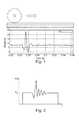
- FIG. 1shows a force signal curve plotted on the ordinate in Newtons versus the time on the abscissa in seconds as it occurs in a typical measurement of an out-of-roundness
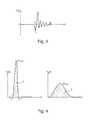
- FIG. 2shows a further force signal curve plotted on the ordinate versus the time on the abscissa, as occurs in a typical measurement of an out-of-roundness, the mean value Fm being already determined from the wheel contact force;
- FIG. 3shows the force signal curve from FIG. 2 , the curve being shown already adjusted by the average Fm;
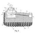
- FIG. 5shows a cross section through a rail with a diagnostic device according to a first embodiment.
- FIG. 1shows the force signal curve as an out-of-round rail vehicle wheel travels over a measuring point or a measuring section.
- the force signal curve in Newtons on the ordinateis plotted versus the time in seconds on the abscissa. It is clear from the force signal curve that, in the area of the out-of-roundness or flattening of the rail vehicle wheel, it first experiences a drop in comparison with the average resulting from the wheel contact force, whereupon a force peak Fmax follows when the out-of-roundness strikes the rail.
- FIG. 2shows a further force signal curve on the ordinate versus time on the abscissa, the mean value Fm, corresponding to the quasi-static wheel contact force, being already determined here.
- the vertical force signalis integrated over the time interval shown.
- the calculated impulse ⁇ right arrow over (I) ⁇is corrected by the proportion of the average F m , which represents the quasi-static wheel force.
- the correction of the force signalcan be effected by calculation or by means of a filter.
- FIG. 3shows the force signal curve from FIG. 2 , which has already been adjusted by the average Fm or the quasi-static wheel contact force.
- the detection of the impulse in the force signal curveis calculated and optimized by an evaluation algorithm. Accordingly, the starting time t 0 and the end time t 2 of the time interval T is determined via the evaluation algorithm.
- FIG. 5shows a diagnostic device 1 of the invention. Diagnostic device 1 is used for determining the out-of-roundness of wheels of rail vehicles.
- a railis identified by the reference character 2 .
- a force sensor in the form of a shear stress sensor 3is connected to an evaluating device 5 via a first electrical line 4 .
- a force sensor 8is provided below rail 2 and within a crossbeam 6 , which is formed as a tie 7 . In this exemplary embodiment, force sensor 8 is designed in the manner of a load cell 9 .
- force sensor 8 or load cell 9is also connected to evaluating device 5 via a line, namely, a second electrical line 10 .
- Crossbeam 6 or tie 7rests on a ballast bed 11 or on a ballastless track.
- Force sensor 8has a strain gauge 12 which is arranged in a blind hole 13 , blind hole 13 being provided in turn in a deforming body or measuring body 14 .
- Force sensor 8is largely defined by a force input element 15 and a force output element 16 .
- Horizontal transverse slits 17 and 18are provided for the defined force flow or for the defined guidance of the force from the input point via the strain gauge 12 to the load output point through force sensor 8 .
Landscapes
- Engineering & Computer Science (AREA)
- Mechanical Engineering (AREA)
- Physics & Mathematics (AREA)
- General Physics & Mathematics (AREA)
- Health & Medical Sciences (AREA)
- Biomedical Technology (AREA)
- General Health & Medical Sciences (AREA)
- Automation & Control Theory (AREA)
- Force Measurement Appropriate To Specific Purposes (AREA)
- Radio Transmission System (AREA)
Abstract
Description
{right arrow over (I)}=Δ{right arrow over (p)}={right arrow over (F)}·Δt. a.
{right arrow over (I)}=Δ{right arrow over (p)}=∫{right arrow over (F)}(t)·dt a.
Claims (11)
Applications Claiming Priority (4)
| Application Number | Priority Date | Filing Date | Title |
|---|---|---|---|
| DE102015002517 | 2015-03-02 | ||
| DE102015002517.1ADE102015002517A1 (en) | 2015-03-02 | 2015-03-02 | Diagnostic device for determining an ovality of rail vehicle wheels according to a force impulse evaluation method |
| DE102015002517.1 | 2015-03-02 | ||
| PCT/EP2016/000352WO2016138986A1 (en) | 2015-03-02 | 2016-03-01 | Diagnostic device for determining an out-of-roundness on rail vehicle wheels in accordance with an impulse evaluation method |
Related Parent Applications (1)
| Application Number | Title | Priority Date | Filing Date |
|---|---|---|---|
| PCT/EP2016/000352ContinuationWO2016138986A1 (en) | 2015-03-02 | 2016-03-01 | Diagnostic device for determining an out-of-roundness on rail vehicle wheels in accordance with an impulse evaluation method |
Publications (2)
| Publication Number | Publication Date |
|---|---|
| US20170363518A1 US20170363518A1 (en) | 2017-12-21 |
| US10365186B2true US10365186B2 (en) | 2019-07-30 |
Family
ID=55453121
Family Applications (1)
| Application Number | Title | Priority Date | Filing Date |
|---|---|---|---|
| US15/695,258Active2036-09-01US10365186B2 (en) | 2015-03-02 | 2017-09-05 | Diagnostic device for detecting an out-of-roundness on railway vehicle wheels in accordance with an impulse evaluation method |
Country Status (6)
| Country | Link |
|---|---|
| US (1) | US10365186B2 (en) |
| EP (1) | EP3265774B1 (en) |
| CN (1) | CN107646004B (en) |
| DE (1) | DE102015002517A1 (en) |
| ES (1) | ES2718027T3 (en) |
| WO (1) | WO2016138986A1 (en) |
Cited By (2)
| Publication number | Priority date | Publication date | Assignee | Title |
|---|---|---|---|---|
| US11926351B2 (en) | 2020-09-01 | 2024-03-12 | Bnsf Railway Company | Apparatus and method for wear detection of railroad vehicle wheels |
| US12441376B2 (en) | 2024-03-11 | 2025-10-14 | Bnsf Railway Company | Apparatus and method for wear detection of railroad vehicle wheels |
Families Citing this family (9)
| Publication number | Priority date | Publication date | Assignee | Title |
|---|---|---|---|---|
| CN107532960B (en)* | 2015-04-28 | 2019-06-18 | 中国铁道科学研究院 | A method and system for full continuous measurement of wheel-rail vertical force on the ground |
| WO2018215144A1 (en)* | 2017-05-24 | 2018-11-29 | Siemens Aktiengesellschaft | Condition controlling of a wear and tear element |
| DE102018117579A1 (en)* | 2018-07-20 | 2020-01-23 | Schenck Process Europe Gmbh | Identification of a rail vehicle wheel |
| DE102019114288A1 (en)* | 2019-05-28 | 2020-12-03 | Lausitz Energie Bergbau Ag | Method and device for localizing a singular flaw on the running surface of a wheel of a rail-bound vehicle |
| HRP20220934T1 (en) | 2019-07-19 | 2022-10-28 | Frauscher Sensortechnik GmbH | RAIL WEAR MEASUREMENT PROCEDURE AND EVALUATION PROCEDURE |
| CN110553861B (en)* | 2019-08-29 | 2022-03-04 | 朔黄铁路发展有限责任公司 | Train information monitoring method, device and equipment |
| CN113776760B (en)* | 2020-06-09 | 2023-06-27 | 成都运达科技股份有限公司 | Train wheel set out-of-round fault monitoring method and system based on whole-axis vibration analysis |
| CN114954562B (en)* | 2022-04-25 | 2024-07-09 | 中国国家铁路集团有限公司 | Low-order wheel polygon recognition method and device |
| AT527202B1 (en)* | 2023-09-21 | 2024-12-15 | Siemens Mobility Austria Gmbh | Method and device for derailment detection for rail vehicles and rail vehicle |
Citations (16)
| Publication number | Priority date | Publication date | Assignee | Title |
|---|---|---|---|---|
| US3844513A (en)* | 1970-04-22 | 1974-10-29 | Ericsson Telefon Ab L M | Method and system for detecting wheel flats on rail vehicles |
| DE3309908A1 (en) | 1982-04-22 | 1983-11-03 | Messerschmitt-Bölkow-Blohm GmbH, 8000 München | Method for detecting flat spots on rail wheels |
| US4679447A (en)* | 1986-01-13 | 1987-07-14 | Amsted Industries Incorporated | Method and apparatus for positioning and testing railroad wheels |
| US5577690A (en)* | 1994-09-15 | 1996-11-26 | Jodon Engineering Associates, Inc. | Microwave measurement of train wheel wear |
| DE19941843A1 (en) | 1999-09-02 | 2001-03-08 | Schenck Process Gmbh | Device for determining out-of-roundness and flat spots on wheels in rail vehicles |
| EP1197417A1 (en) | 2000-10-12 | 2002-04-17 | Siemens SGP Verkehrstechnik GmbH | Method and apparatus for detecting defects on the wheels of a railway vehicle |
| DE20317201U1 (en) | 2003-11-05 | 2004-03-18 | Db Cargo Ag | Train wheel tread distortion measurement unit calculates average value and Fourier transform parameters to locate worst distortion from wheel bearing error |
| WO2006125237A1 (en) | 2005-05-25 | 2006-11-30 | Hottinger Baldwin Messtechnik Gmbh | Method and device for detecting wheel shapes of rail wheels |
| EP1839990A2 (en) | 2006-03-31 | 2007-10-03 | Bernd Neuroth | Assembly for checking the wheels of rail vehicles |
| US20080304065A1 (en)* | 2004-09-11 | 2008-12-11 | General Electric Company | Rail Sensing Apparatus Method |
| EP2631150A1 (en) | 2012-02-24 | 2013-08-28 | Tamtron Systems Oy | Improved method and arrangement for measuring characteristics of a vehicle travelling on a rail |
| US20140110534A1 (en)* | 2012-10-24 | 2014-04-24 | Progress Rail Services Corporation | Flat wheel detector with multiple sensors |
| US20160031458A1 (en)* | 2013-04-01 | 2016-02-04 | Universidad Eafit | System for detecting defects in the roundness of railway vehicle wheels |
| US20170169145A1 (en)* | 2014-08-29 | 2017-06-15 | Schenck Process Europe Gmbh | Device and method for determining geometry characteristic values of a wheel profile on a rolling wheel of a rail vehicle |
| US20180037240A1 (en)* | 2016-08-08 | 2018-02-08 | General Electric Company | Wheel deformity warning system |
| US20180283992A1 (en)* | 2017-05-29 | 2018-10-04 | Alireza Alemi | Wheel condition monitoring |
Family Cites Families (2)
| Publication number | Priority date | Publication date | Assignee | Title |
|---|---|---|---|---|
| DE102009041823A1 (en)* | 2009-09-18 | 2011-03-24 | Knorr-Bremse Systeme für Schienenfahrzeuge GmbH | Method and device for monitoring the driving behavior of a rail vehicle |
| AT515500A1 (en)* | 2014-03-12 | 2015-09-15 | Siemens Ag Oesterreich | Device and method for obstacle detection in rail vehicles |
- 2015
- 2015-03-02DEDE102015002517.1Apatent/DE102015002517A1/ennot_activeWithdrawn
- 2016
- 2016-03-01ESES16707635Tpatent/ES2718027T3/enactiveActive
- 2016-03-01EPEP16707635.5Apatent/EP3265774B1/enactiveActive
- 2016-03-01CNCN201680012916.6Apatent/CN107646004B/enactiveActive
- 2016-03-01WOPCT/EP2016/000352patent/WO2016138986A1/ennot_activeCeased
- 2017
- 2017-09-05USUS15/695,258patent/US10365186B2/enactiveActive
Patent Citations (18)
| Publication number | Priority date | Publication date | Assignee | Title |
|---|---|---|---|---|
| US3844513A (en)* | 1970-04-22 | 1974-10-29 | Ericsson Telefon Ab L M | Method and system for detecting wheel flats on rail vehicles |
| DE3309908A1 (en) | 1982-04-22 | 1983-11-03 | Messerschmitt-Bölkow-Blohm GmbH, 8000 München | Method for detecting flat spots on rail wheels |
| US4679447A (en)* | 1986-01-13 | 1987-07-14 | Amsted Industries Incorporated | Method and apparatus for positioning and testing railroad wheels |
| US5577690A (en)* | 1994-09-15 | 1996-11-26 | Jodon Engineering Associates, Inc. | Microwave measurement of train wheel wear |
| DE19941843A1 (en) | 1999-09-02 | 2001-03-08 | Schenck Process Gmbh | Device for determining out-of-roundness and flat spots on wheels in rail vehicles |
| EP1212228A1 (en) | 1999-09-02 | 2002-06-12 | Schenck Process GmbH | Device for detecting eccentricities or wheel flats of rail vehicle wheels |
| EP1212228B1 (en) | 1999-09-02 | 2003-04-09 | Schenck Process GmbH | Device for detecting eccentricities or wheel flats of rail vehicle wheels |
| EP1197417A1 (en) | 2000-10-12 | 2002-04-17 | Siemens SGP Verkehrstechnik GmbH | Method and apparatus for detecting defects on the wheels of a railway vehicle |
| DE20317201U1 (en) | 2003-11-05 | 2004-03-18 | Db Cargo Ag | Train wheel tread distortion measurement unit calculates average value and Fourier transform parameters to locate worst distortion from wheel bearing error |
| US20080304065A1 (en)* | 2004-09-11 | 2008-12-11 | General Electric Company | Rail Sensing Apparatus Method |
| WO2006125237A1 (en) | 2005-05-25 | 2006-11-30 | Hottinger Baldwin Messtechnik Gmbh | Method and device for detecting wheel shapes of rail wheels |
| EP1839990A2 (en) | 2006-03-31 | 2007-10-03 | Bernd Neuroth | Assembly for checking the wheels of rail vehicles |
| EP2631150A1 (en) | 2012-02-24 | 2013-08-28 | Tamtron Systems Oy | Improved method and arrangement for measuring characteristics of a vehicle travelling on a rail |
| US20140110534A1 (en)* | 2012-10-24 | 2014-04-24 | Progress Rail Services Corporation | Flat wheel detector with multiple sensors |
| US20160031458A1 (en)* | 2013-04-01 | 2016-02-04 | Universidad Eafit | System for detecting defects in the roundness of railway vehicle wheels |
| US20170169145A1 (en)* | 2014-08-29 | 2017-06-15 | Schenck Process Europe Gmbh | Device and method for determining geometry characteristic values of a wheel profile on a rolling wheel of a rail vehicle |
| US20180037240A1 (en)* | 2016-08-08 | 2018-02-08 | General Electric Company | Wheel deformity warning system |
| US20180283992A1 (en)* | 2017-05-29 | 2018-10-04 | Alireza Alemi | Wheel condition monitoring |
Non-Patent Citations (1)
| Title |
|---|
| International Search Report dated May 24, 2016 (English Translation). |
Cited By (3)
| Publication number | Priority date | Publication date | Assignee | Title |
|---|---|---|---|---|
| US11926351B2 (en) | 2020-09-01 | 2024-03-12 | Bnsf Railway Company | Apparatus and method for wear detection of railroad vehicle wheels |
| US11926352B2 (en) | 2020-09-01 | 2024-03-12 | Bnsf Railway Company | Apparatus and method for wear detection of railroad vehicle wheels |
| US12441376B2 (en) | 2024-03-11 | 2025-10-14 | Bnsf Railway Company | Apparatus and method for wear detection of railroad vehicle wheels |
Also Published As
| Publication number | Publication date |
|---|---|
| EP3265774B1 (en) | 2019-01-30 |
| CN107646004A (en) | 2018-01-30 |
| CN107646004B (en) | 2020-03-27 |
| ES2718027T3 (en) | 2019-06-27 |
| WO2016138986A1 (en) | 2016-09-09 |
| US20170363518A1 (en) | 2017-12-21 |
| DE102015002517A1 (en) | 2016-09-08 |
| EP3265774A1 (en) | 2018-01-10 |
Similar Documents
| Publication | Publication Date | Title |
|---|---|---|
| US10365186B2 (en) | Diagnostic device for detecting an out-of-roundness on railway vehicle wheels in accordance with an impulse evaluation method | |
| US7681443B2 (en) | Apparatus for detecting hunting and angle of attack of a rail vehicle wheelset | |
| Žnidarič et al. | Railway bridge Weigh-in-Motion system | |
| JP2013174481A (en) | Vehicle axle load measurement system and bridge monitoring system using the same | |
| WO2001017837A1 (en) | Device for detecting eccentricities or wheel flats of rail vehicle wheels | |
| JP3574850B2 (en) | Axle load measurement method for vehicles running on bridges | |
| DE10304008B4 (en) | Device for measuring the rail load | |
| JP2008051571A (en) | Wheel shape measuring device for railway vehicles | |
| CN111397714A (en) | Dynamic weighing sensor and measuring method thereof | |
| US6820460B1 (en) | System for monitoring the working of rotation or roll dampers | |
| US12216028B2 (en) | Derivation method, derivation device, derivation system, and program | |
| KR102501494B1 (en) | Evaluation system and method for track impact factor and runnig stability | |
| JP7120934B2 (en) | Railway vehicle monitoring system | |
| CN118019679A (en) | System and method for diagnosing abnormal bending of railway rails, especially at the joints between railway rails | |
| RU2239798C2 (en) | Method of weighing vehicle | |
| JP2018086876A (en) | Method and device for measuring ride comfort | |
| CN115812117A (en) | Machine and method for compacting a ballast bed of a track | |
| CN211401386U (en) | Dynamic weighing sensor and dynamic weighing device | |
| RU2733939C2 (en) | Method of estimating state of spring suspension of rolling stock bogies and device for implementation thereof | |
| GB2563909A (en) | Railway vehicle wheel detection apparatus and method | |
| KR200481415Y1 (en) | Gravimetry Unit for Streetcar | |
| RU30191U1 (en) | Device for axial weighing of railway objects | |
| JPS6130209B2 (en) | ||
| CN118922344A (en) | Method and device for approximating an acceleration signal profile detected when a rail vehicle travels over a measuring section to a characteristic of a corresponding force signal profile | |
| JPS582373B2 (en) | Tire flat cover |
Legal Events
| Date | Code | Title | Description |
|---|---|---|---|
| FEPP | Fee payment procedure | Free format text:ENTITY STATUS SET TO UNDISCOUNTED (ORIGINAL EVENT CODE: BIG.); ENTITY STATUS OF PATENT OWNER: LARGE ENTITY | |
| AS | Assignment | Owner name:SCHENCK PROCESS EUROPE GMBH, GERMANY Free format text:ASSIGNMENT OF ASSIGNORS INTEREST;ASSIGNORS:EHMKE, FRITZ;RAIS, VIKTOR;SIGNING DATES FROM 20170911 TO 20170912;REEL/FRAME:043611/0895 | |
| STPP | Information on status: patent application and granting procedure in general | Free format text:DOCKETED NEW CASE - READY FOR EXAMINATION | |
| AS | Assignment | Owner name:SCHENCK PROCESS EUROPE GMBH, GERMANY Free format text:MERGER AND CHANGE OF NAME;ASSIGNORS:SCHENCK PROCESS EUROPE GMBH;SCHENCK PROCESS ASIA HOLDING GMBH;REEL/FRAME:049213/0134 Effective date:20180717 | |
| STPP | Information on status: patent application and granting procedure in general | Free format text:NOTICE OF ALLOWANCE MAILED -- APPLICATION RECEIVED IN OFFICE OF PUBLICATIONS | |
| STPP | Information on status: patent application and granting procedure in general | Free format text:PUBLICATIONS -- ISSUE FEE PAYMENT VERIFIED | |
| STCF | Information on status: patent grant | Free format text:PATENTED CASE | |
| MAFP | Maintenance fee payment | Free format text:PAYMENT OF MAINTENANCE FEE, 4TH YEAR, LARGE ENTITY (ORIGINAL EVENT CODE: M1551); ENTITY STATUS OF PATENT OWNER: LARGE ENTITY Year of fee payment:4 | |
| AS | Assignment | Owner name:QLAR EUROPE GMBH, GERMANY Free format text:CHANGE OF NAME;ASSIGNOR:SCHENCK PROCESS EUROPE GMBH;REEL/FRAME:071541/0863 Effective date:20240902 |