US10363561B2 - Apparatus for shredding of waste - Google Patents
Apparatus for shredding of wasteDownload PDFInfo
- Publication number
- US10363561B2 US10363561B2US15/001,082US201615001082AUS10363561B2US 10363561 B2US10363561 B2US 10363561B2US 201615001082 AUS201615001082 AUS 201615001082AUS 10363561 B2US10363561 B2US 10363561B2
- Authority
- US
- United States
- Prior art keywords
- rotating core
- waste
- main shaft
- longitudinal axis
- blades
- Prior art date
- Legal status (The legal status is an assumption and is not a legal conclusion. Google has not performed a legal analysis and makes no representation as to the accuracy of the status listed.)
- Expired - Fee Related, expires
Links
Images


Classifications
- B—PERFORMING OPERATIONS; TRANSPORTING
- B02—CRUSHING, PULVERISING, OR DISINTEGRATING; PREPARATORY TREATMENT OF GRAIN FOR MILLING
- B02C—CRUSHING, PULVERISING, OR DISINTEGRATING IN GENERAL; MILLING GRAIN
- B02C13/00—Disintegrating by mills having rotary beater elements ; Hammer mills
- B02C13/13—Disintegrating by mills having rotary beater elements ; Hammer mills with horizontal rotor shaft and combined with sifting devices, e.g. for making powdered fuel
- B—PERFORMING OPERATIONS; TRANSPORTING
- B02—CRUSHING, PULVERISING, OR DISINTEGRATING; PREPARATORY TREATMENT OF GRAIN FOR MILLING
- B02C—CRUSHING, PULVERISING, OR DISINTEGRATING IN GENERAL; MILLING GRAIN
- B02C18/00—Disintegrating by knives or other cutting or tearing members which chop material into fragments
- B02C18/0084—Disintegrating by knives or other cutting or tearing members which chop material into fragments specially adapted for disintegrating garbage, waste or sewage
- B—PERFORMING OPERATIONS; TRANSPORTING
- B02—CRUSHING, PULVERISING, OR DISINTEGRATING; PREPARATORY TREATMENT OF GRAIN FOR MILLING
- B02C—CRUSHING, PULVERISING, OR DISINTEGRATING IN GENERAL; MILLING GRAIN
- B02C18/00—Disintegrating by knives or other cutting or tearing members which chop material into fragments
- B02C18/06—Disintegrating by knives or other cutting or tearing members which chop material into fragments with rotating knives
- B02C18/08—Disintegrating by knives or other cutting or tearing members which chop material into fragments with rotating knives within vertical containers
- B—PERFORMING OPERATIONS; TRANSPORTING
- B02—CRUSHING, PULVERISING, OR DISINTEGRATING; PREPARATORY TREATMENT OF GRAIN FOR MILLING
- B02C—CRUSHING, PULVERISING, OR DISINTEGRATING IN GENERAL; MILLING GRAIN
- B02C18/00—Disintegrating by knives or other cutting or tearing members which chop material into fragments
- B02C18/06—Disintegrating by knives or other cutting or tearing members which chop material into fragments with rotating knives
- B02C18/14—Disintegrating by knives or other cutting or tearing members which chop material into fragments with rotating knives within horizontal containers
- B—PERFORMING OPERATIONS; TRANSPORTING
- B02—CRUSHING, PULVERISING, OR DISINTEGRATING; PREPARATORY TREATMENT OF GRAIN FOR MILLING
- B02C—CRUSHING, PULVERISING, OR DISINTEGRATING IN GENERAL; MILLING GRAIN
- B02C18/00—Disintegrating by knives or other cutting or tearing members which chop material into fragments
- B02C18/06—Disintegrating by knives or other cutting or tearing members which chop material into fragments with rotating knives
- B02C18/16—Details
- B02C18/22—Feed or discharge means
- B02C18/2225—Feed means
- B02C18/2291—Feed chute arrangements
- B—PERFORMING OPERATIONS; TRANSPORTING
- B02—CRUSHING, PULVERISING, OR DISINTEGRATING; PREPARATORY TREATMENT OF GRAIN FOR MILLING
- B02C—CRUSHING, PULVERISING, OR DISINTEGRATING IN GENERAL; MILLING GRAIN
- B02C18/00—Disintegrating by knives or other cutting or tearing members which chop material into fragments
- B02C18/06—Disintegrating by knives or other cutting or tearing members which chop material into fragments with rotating knives
- B02C18/16—Details
- B02C18/24—Drives
- B—PERFORMING OPERATIONS; TRANSPORTING
- B02—CRUSHING, PULVERISING, OR DISINTEGRATING; PREPARATORY TREATMENT OF GRAIN FOR MILLING
- B02C—CRUSHING, PULVERISING, OR DISINTEGRATING IN GENERAL; MILLING GRAIN
- B02C23/00—Auxiliary methods or auxiliary devices or accessories specially adapted for crushing or disintegrating not provided for in preceding groups or not specially adapted to apparatus covered by a single preceding group
- B02C23/08—Separating or sorting of material, associated with crushing or disintegrating
- B02C23/16—Separating or sorting of material, associated with crushing or disintegrating with separator defining termination of crushing or disintegrating zone, e.g. screen denying egress of oversize material
- B—PERFORMING OPERATIONS; TRANSPORTING
- B02—CRUSHING, PULVERISING, OR DISINTEGRATING; PREPARATORY TREATMENT OF GRAIN FOR MILLING
- B02C—CRUSHING, PULVERISING, OR DISINTEGRATING IN GENERAL; MILLING GRAIN
- B02C23/00—Auxiliary methods or auxiliary devices or accessories specially adapted for crushing or disintegrating not provided for in preceding groups or not specially adapted to apparatus covered by a single preceding group
- B02C23/18—Adding fluid, other than for crushing or disintegrating by fluid energy
- B02C23/24—Passing gas through crushing or disintegrating zone
- B—PERFORMING OPERATIONS; TRANSPORTING
- B02—CRUSHING, PULVERISING, OR DISINTEGRATING; PREPARATORY TREATMENT OF GRAIN FOR MILLING
- B02C—CRUSHING, PULVERISING, OR DISINTEGRATING IN GENERAL; MILLING GRAIN
- B02C23/00—Auxiliary methods or auxiliary devices or accessories specially adapted for crushing or disintegrating not provided for in preceding groups or not specially adapted to apparatus covered by a single preceding group
- B02C23/08—Separating or sorting of material, associated with crushing or disintegrating
- B02C23/16—Separating or sorting of material, associated with crushing or disintegrating with separator defining termination of crushing or disintegrating zone, e.g. screen denying egress of oversize material
- B02C2023/165—Screen denying egress of oversize material
Definitions
- the present disclosurerelates to a field of waste management. More specifically, the present disclosure relates to an apparatus to shred waste.
- wasteIn the recent years, the amount of waste has increased sharply. This increase can be attributed to factors such as increased demand and production of livestock and agricultural produce, mismanagement of livestock and agricultural produce, lack of proper waste management resources and the like.
- the wasteprimarily includes municipal waste, green waste, organic waste and the like. This waste occupies large sections of land. This waste does not decompose properly and affects the soil quality, air quality and water resource present in the vicinity. In addition, this waste is wet, has a bad odor and contains harmful bacteria. In addition, this occupancy of waste poses negative psychological impact on the neighborhood. To overcome this, the waste is shredded and grinded. In conventional treatment methods, the waste obtained from municipal dump areas is commonly transferred to multiple chambers equipped with shredding blades housed in large mechanical structures.
- an apparatusfor waste reduction and preparation for subsequent recycling or disposal in a self-contained system.
- the apparatusincludes a preferably-shaped hopper for receiving organic materials to the reduced, preferably a floating auger, a solids pump and a macerator.
- the systempreferably generates a processed organic material discharge with a particle size on the order of 1 ⁇ 8′′ without concern as to the liquid content of the incoming organic material.
- an apparatus for recycling waste material into reusable compostincludes a compact, self-contained housing having a component section and a decomposition chamber.
- the waste materialis ground and mixed in the component section and then conveyed to the decomposition chamber by a conveyor which disperses the homogenous waste longitudinally.
- the homogeneous wasteis dispersed laterally within the decomposition chamber.
- a blowerdirects aerating air into the decomposition chamber and the air is re-circulated back to the blower, where the re-circulated air is mixed with a predetermined amount of incoming fresh air, and a portion of the recirculating air is exhausted to atmosphere, the exhausting air being filtered prior to being exhausted. Thereafter, the resulting compost is removed by an auger through a discharge opening of the decomposition chamber.
- a shredderin yet another prior art, includes a shaft which carries first and second sets of cutters. Each set of cutters is arranged around the shaft along respective helical paths. The first set of cutters is arranged to feed out material towards one end of the shaft. The second set of cutters is arranged to feed cut material towards the other end of the shaft.
- the present disclosureprovides an apparatus for shredding a pre-defined amount of waste.
- the apparatusincludes a main frame positioned to provide support to the apparatus. Further, the apparatus includes a rotating core to shred, masticate and grind the pre-defined amount of waste. Furthermore, the apparatus includes a body mechanically linked to the main frame through a linkage plate. Moreover, the apparatus includes a hopper mounted vertically on the body. Further, the apparatus includes a first set of mash double row ball bearings symmetrically positioned near the first distal end of the main shaft. In addition, the apparatus includes a second set of mash double row ball bearings symmetrically positioned near the second distal end of the main shaft.
- the main frameis a metallic frame having a plurality of balance points.
- the rotating coreis mounted on the main frame and horizontally positioned for rotation along a longitudinal axis. Further, the rotating core includes a main shaft symmetrically positioned along the longitudinal axis. Furthermore, the rotating core includes one or more shafts aligned gradually along the longitudinal axis with a first pre-defined range of angular separation. In addition, the rotating core includes one or more shaft blades adjustably mounted to the one or more shafts.
- the main shaftis mechanically coupled to a motor shaft of an electric motor through a radial bearing and double row mobile pulley assembly. Further, the main shaft includes a first distal end and a second distal end symmetrically from a center of the main shaft.
- Each shaft blade of the one or more shaft bladeis positioned in a staggered orientation about the longitudinal axis. Moreover, each shaft blade of the one or more shaft blades is staggered at a second pre-defined range of angular separation. Further, a plurality of rubber spacers is positioned between the linkage plate and the main frame at each of the plurality of balance points. Moreover, the body is designed to support the rotation of the rotating core. The body includes a plurality of vertical blades mounted within the body. Further, the body includes a plurality of horizontal blades mounted on the body. Furthermore, the body includes a first cooling chamber mechanically connected to a first end of the body and a second cooling chamber mechanically connected to a second section of the body.
- each of the plurality of vertical bladesis curved to symmetrically contour the rotating core along a vertical axis.
- Each of the plurality of horizontal bladesis aligned with the one or more shaft blades along a horizontal axis.
- the first cooling chamber and the second cooling chamberare mechanically coupled to a cooling system.
- the hopperincludes an ingress cross sectional opening to receive the pre-defined amount of waste.
- the hopperincludes an egress cross-sectional opening to transfer the pre-defined amount of waste inside the rotating core.
- the ingress cross-sectional opening of the hopperis greater than the egress cross-sectional opening of the hopper.
- the first set of mash double row ball bearingsis enclosed in a bearing cover coincidently placed around the longitudinal axis.
- the second set of double row ball bearingsis enclosed in the bearing cover coincidently placed around the longitudinal axis.
- the first endis located at a mounting position of the hopper and the second end is located at the mounting position of body on the main frame.
- the apparatusfurther includes a bottom lid screen housing positioned upside down and mounted on the second end of the body.
- a first holding hookis attached on a surface of the bottom lid screen housing and a second holding hook is attached on a surface of the hopper.
- the main framehas a first section for holding a motor mount and a second section for holding the body.
- the apparatusfurther includes a motor mount positioned adjacent to the body and mounted on a first section of the frame.
- the motor mountincludes a plurality of holders designed to mount the electric motor and a hydraulic motor.
- the apparatusfurther includes a hydraulic system installed in the apparatus.
- the hydraulic systemis installed to vary an angle of inclination of the hopper.
- the apparatusfurther includes a first hydraulic cylinder.
- the first hydraulic cylinderhas a first holding end and a second holding end.
- the first holding end of the hydraulic cylinderis mechanically attached to a second holding hook of the hopper.
- the second holding end of the first hydraulic cylinderis mechanically coupled to a hydraulic motor.
- the apparatusfurther includes a second hydraulic cylinder.
- the second hydraulic cylinderhas a third holding end and a fourth holding end.
- the third holding end of the second hydraulic cylinderis mechanically attached to a first holding hook of the bottom lid screen housing.
- the fourth holding end of the first hydraulic cylinderis mechanically coupled to the hydraulic motor.
- the apparatusincludes a hydraulic motor mounted on a motor mount and positioned adjacent to the electric motor.
- the hydraulic motoris configured to pump a liquid at a pre-defined pressure inside the first hydraulic cylinder and the second hydraulic cylinder.
- the apparatusincludes a cooling system installed in the apparatus for a reduction in heat generated from the rotation of the plurality of vertical blades and the plurality of horizontal blades.
- the cooling systemincludes an electrical pump mechanically coupled with each of a plurality of conduits and a coolant present inside each of the plurality of conduits.
- Each of the plurality of conduitsis mechanically coupled to the first cooling chamber and the second cooling chamber of the body.
- the apparatusfurther includes a grate mounted horizontally on the second end of the body.
- the grateis a metallic frame that has a pre-defined shape and a pre-defined size of a plurality of perforations.
- the apparatusfurther includes a scraper blade designed to extend past the plurality of horizontal blades.
- the scraper bladeis designed to have a separation of 1 inch from the plurality of horizontal blades.
- the scraper bladeis positioned for scraping material left attached to each of the plurality of horizontal blades after shredding of the pre-defined amount of waste.
- the apparatusfurther includes a first flywheel mounted at a first distal end of the main shaft.
- the first flywheelhas a first axis coinciding with the longitudinal axis.
- the apparatusfurther includes a second flywheel mounted at a second distal end of the main shaft.
- the second flywheelhas a second axis coinciding with the longitudinal axis.
- the first flywheel and the second flywheelare symmetrically placed apart from the center of the main shaft.
- the first flywheel and the second flywheelare positioned to counter balance any abrupt change in a speed of rotation of the first shaft.
- the first pre-defined range of angular separationis 3O-15O.
- the second pre-defined range of angular separationis 75O-98O.
- the present disclosureprovides an apparatus for shredding a pre-defined amount of waste.
- the apparatusincludes a main frame positioned to provide support to the apparatus. Further, the apparatus includes a rotating core to shred, masticate and grind the pre-defined amount of waste. Furthermore, the apparatus includes a body mechanically linked to the main frame through a linkage plate. Moreover, the apparatus includes a hopper mounted vertically on the body. Moreover, the apparatus includes a first flywheel mounted at a first distal end of the main shaft. In addition, the apparatus includes a second flywheel mounted at a second distal end of the main shaft. Further, the apparatus includes a first set of mash double row ball bearings symmetrically positioned near the first distal end of the main shaft.
- the apparatusincludes a second set of mash double row ball bearings symmetrically positioned near the second distal end of the main shaft.
- the main frameis a metallic frame having a plurality of balance points.
- the rotating coreis mounted on the main frame and horizontally positioned for rotation along a longitudinal axis.
- the rotating coreincludes a main shaft symmetrically positioned along the longitudinal axis.
- the rotating coreincludes one or more shafts aligned gradually along the longitudinal axis with a first pre-defined range of angular separation.
- the rotating coreincludes one or more shaft blades adjustably mounted to the one or more shafts.
- the main shaftis mechanically coupled to a motor shaft of an electric motor through a radial bearing and double row mobile pulley assembly.
- the main shaftincludes a first distal end and a second distal end symmetrically from a center of the main shaft.
- Each shaft blade of the one or more shaft bladeis positioned in a staggered orientation about the longitudinal axis.
- each shaft blade of the one or more shaft bladesis staggered at a second pre-defined range of angular separation.
- a plurality of rubber spacersis positioned between the linkage plate and the main frame at each of the plurality of balance points.
- the bodyis designed to support the rotation of the rotating core.
- the bodyincludes a plurality of vertical blades mounted within the body. Further, the body includes a plurality of horizontal blades mounted on the body.
- the bodyincludes a first cooling chamber mechanically connected to a first end of the body and a second cooling chamber mechanically connected to a second section of the body.
- each of the plurality of vertical bladesis curved to symmetrically contour the rotating core along a vertical axis.
- Each of the plurality of horizontal bladesis aligned with the one or more shaft blades along a horizontal axis.
- the first cooling chamber and the second cooling chamberare mechanically coupled to a cooling system.
- the first flywheelhas a first axis coinciding with the longitudinal axis.
- the second flywheelhas a second axis coinciding with the longitudinal axis. The first flywheel and the second flywheel are symmetrically placed apart from the center of the main shaft.
- the first flywheel and the second flywheelare positioned to counter balance any abrupt change in a speed of rotation of the first shaft.
- the hopperincludes ingress cross-sectional opening to receive the pre-defined amount of waste.
- the hopperincludes an egress cross-sectional opening to transfer the pre-defined amount of waste inside the rotating core.
- the ingress cross-sectional opening of the hopperis greater than the egress cross-sectional opening of the hopper.
- the first set of mash double row ball bearingsis enclosed in a bearing cover coincidently placed around the longitudinal axis.
- the second set of double row ball bearingsis enclosed in the bearing cover coincidently placed around the longitudinal axis.
- the apparatusfurther includes a bottom lid screen housing positioned upside down and mounted on the second end of the body.
- a first holding hookis attached on a surface of the bottom lid screen housing and a second holding hook is attached on a surface of the hopper.
- the apparatusfurther includes a grate mounted horizontally on the second end of the body.
- the grateis a metallic frame that has a pre-defined shape and a pre-defined size of a plurality of perforations.
- the apparatusfurther includes a scraper blade designed to extend past the plurality of horizontal blades.
- the scraper bladeis designed to have a separation of 1 inch from the plurality of horizontal blades.
- the scraper bladeis positioned for scraping material left attached to each of the plurality of horizontal blades after shredding of the pre-defined amount of waste.
- FIG. 1Aillustrates a perspective view of an apparatus for shredding of waste, in accordance with an embodiment of the present disclosure
- FIG. 1Billustrates the perspective view of the apparatus of FIG. 1A without cover, in accordance with an embodiment of the present disclosure
- FIG. 1Cillustrates a side view of the apparatus of FIG. 1B , in accordance with an embodiment of the present of the present disclosure
- FIG. 1Dillustrates a front view of the apparatus of FIG. 1A , in accordance with an embodiment of the present disclosure
- FIG. 2Aillustrates a perspective view of a rotating core of the apparatus of FIG. 1A , in accordance with an embodiment of the present disclosure
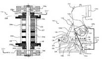
- FIG. 2Billustrates a sectional view of the rotating core of FIG. 2A having flywheels, in accordance with an embodiment of the present disclosure
- FIG. 2Cillustrates an inside view of a body of the apparatus of FIG. 1A without the rotating core, in accordance with an embodiment of the present disclosure
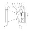
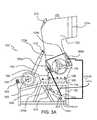
- FIG. 3Aillustrates a schematic view and a side view of the apparatus of FIG. 1A , in accordance with an embodiment of the present disclosure
- FIG. 3Billustrates the schematic view and the side view of the body with the rotating core, in accordance with an embodiment of the present disclosure.
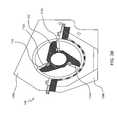
- FIG. 3Cillustrates a perspective view of a scraper assembly of the apparatus of FIG. 1A , in accordance with an embodiment of the present disclosure.
- FIG. 1Aillustrates a perspective view of an apparatus 100 for shredding of a pre-defined amount of waste, in accordance with an embodiment of the present disclosure.
- the apparatus 100is a mechanical device configured to shred, masticate and grind the pre-defined amount of waste. Further, the pre-defined amount of waste is shredded based on a capacity of the apparatus 100 .
- the pre-defined amount of wasteis obtained from a plurality of sources.
- the pre-defined amount of wasteincludes waste livestock, animal excreta, municipal solid waste, green waste, organic waste and the like. In general, the pre-defined amount of waste primarily includes large solid mass of waste along with water. Further, the pre-defined amount of waste is shredded for reducing size of individual pieces of waste and removal of a pre-defined amount of water.
- the apparatus 100includes a main frame 102 , a plurality of rubber spacers 104 a - b , a linkage plate 106 , a body 108 , one or more shafts 110 , one or more shaft blades 112 , a rotating core 114 , a first flywheel cover 116 , a second flywheel cover 118 , a collection tank 120 and a hopper 122 .
- the above mentioned parts of the apparatus 100are designed and assembled to shred the pre-defined amount of waste.
- the apparatus 100is physically supported by the main frame 102 .
- the main frame 102is a metallic frame positioned to provide support to the apparatus 100 .
- the main frame 102includes a plurality of balance points. Each of the plurality of balance points is distributed discreetly across the main frame 102 .
- the linkage plate 106is horizontally positioned on the main plate 102 .
- the linkage plate 106is a metallic plate designed to provide a rigid and flat base for assembled parts of the apparatus 100 .
- the linkage plate 106has a first plurality of holes designed to couple with a mountable part of the apparatus 100 .
- the plurality of rubber spacers 104 a - bare inserted between each of the plurality of balance points of the main frame 102 and the linkage plate 106 .
- Each of the plurality of rubber spacers 104 a - bis made of a hard rubber material designed to provide a cushioning effect to the apparatus 100 .
- the apparatus 100produces vibrations in operating mode. Further, a continuous flow of vibrations may loosen joints between the parts of the apparatus 100 .
- each of the plurality of rubber spacers 104 a - bis designed to absorb the vibrations produced from the operating mode.
- each of the plurality of rubber spacers 104 a - bis positioned between each of the plurality of balance points.
- Each of the plurality of rubber spacers 104 a - bhave a pre-defined shape.
- the pre-defined shape of each of the plurality of rubber spacers 104 a - bis cylindrical.
- the pre-defined shape of each of the plurality of rubber spacers 104 a - bis cuboidal.
- each of the plurality of rubber spacers 104 a - bmay have any suitable shape.
- the body 108is mechanically linked to the main frame 102 through the linkage plate 106 .
- the body 108includes a second plurality of holes.
- the first plurality of holes of the linkage plate 106is aligned with the second plurality of holes of the body 108 .
- the body 108is mechanically linked through insertion of a plurality of bolts inside an aligned first plurality of holes and the second plurality of holes.
- the body 108is aligned along a longitudinal axis.
- the longitudinal axispasses through a center of the rotating core 114 .
- the body 100includes a first end 108 a and a second end 108 b .
- the body 108has a cylindrical shape with spacing for a plurality of screens 207 .
- Each of the plurality of screens 207(as shown in FIG. 2B ) is used to size the pre-defined amount of waste. If the pre-defined amount of waste is not divided sufficiently in a first cycle of a plurality of cycles, the apparatus 100 makes subsequent cuts to the waste to reduce size of the waste. The subsequent cut to the pre-defined amount of waste are performed to facilitate exit of the waste outside the plurality of screens 207 .
- the body 108further includes a plurality of horizontal blades 204 a - 204 d , one or more mounts 214 and a plurality of vertical blades 212 a - 212 d respectively. Further, each of the plurality of horizontal blades 204 a - 204 d is mounted on the one or more mounts 214 present within the body 108 . In addition, each of the plurality of horizontal blades 204 a - 204 d is aligned with the one or more shaft blades 112 along a horizontal axis.
- each of the plurality of horizontal blades 204 a - 204 dis a fixed blade designed to remain in a mounting position provided by the one or more mounts 214 .
- the plurality of vertical blades 212 a - 212 dis mounted within the body 108 .
- Each of the plurality of vertical blades 212 a - 212 dis curved to symmetrically contour the rotating core 114 along a vertical axis.
- the pre-defined amount of wasteis gravitationally fed to the rotating core 114 .
- the pre-defined amount of wasteis trapped between the plurality of horizontal blades 204 a - 204 d and the plurality of vertical blades 212 a - 212 d .
- the rotating core 114tears apart the pre-defined amount of waste with each rotation.
- the body 108 of the apparatus 100encapsulates the rotating core 114 .
- the rotating core 114is configured to shred, masticate and grind the pre-defined amount of waste. Further, the rotating core 114 is positioned concentrically within the body 108 for a pre-defined speed of rotation along the longitudinal axis.
- the rotating core 114includes a main shaft 202 .
- the main shaft 202is symmetrically positioned along the longitudinal axis.
- the main shaft 202is mechanically coupled to a motor shaft 309 (as shown in FIG. 3A ) of an electric motor 128 (as shown in FIG. 1C and FIG. 3A ) through a radial bearing and double row mobile pulley assembly.
- the main shaft 202includes a first distal end 110 a and a second distal end 110 b symmetrically from a center of the main shaft 202 .
- the main shaft 202is a cylindrical solid metallic rod.
- one or more shafts 110(as shown in FIG. 1B and FIG. 2A ) are mounted mechanically in a staggered orientation.
- Each of the one or more shafts 110are aligned gradually along the longitudinal axis with a first pre-defined range of angular separation.
- the first pre-defined range of angular separationis 3°-15°.
- the angular separationmay be any acute angle.
- Each shaft of the one or more shafts 110is staggered at the pre-defined range of angular separation.
- each of the one or more shafts 110is made from joining corners of two polygonal metallic plates with metallic bars aligned parallel to the longitudinal axis.
- one or more shaft blades 112 a - 112 care adjustably mounted on each of the one or more shafts 110 . Further, each shaft blade of the one or more shaft blades 112 a - 112 c is positioned in a staggered orientation about the longitudinal axis. Moreover, each shaft blade of the one or more shaft blades 112 a - 112 c is staggered at a second pre-defined range of angular separation. In an embodiment of the present disclosure, the second pre-defined range of angular separation is 75°-98°. It may be noted that the second pre-defined range is 75°-98°, however; those skilled in the art would appreciate that the any suitable angular separation may be selected for optimized shredding of the pre-defined amount of waste.
- a first flywheel 124 a and a second flywheel 124 bare mounted at the first distal end 110 a and the second distal end 110 b of the main shaft 202 . Further, a first axis of the first flywheel 124 a and a second axis of the second flywheel 124 b coincide with the longitudinal axis.
- the first flywheel 124 a and the second flywheel 124 bare symmetrically placed apart from the center of the main shaft 202 . Furthermore, the first flywheel 124 a and the second flywheel 124 b are positioned to counter balance any abrupt change in the pre-defined speed of rotation of the main shaft 202 .
- first flywheel 124 a and the second flywheel 124 bare a rotational mechanical device designed to store rotational energy produced from the rotation of the main shaft 202 . Further, the first flywheel 124 a and the second flywheel 124 b have a moment of inertia that resists any abrupt change in speed of rotation. Accordingly, the first flywheel 124 a and the second flywheel 124 b regulate a constant speed of rotation of the main shaft 202 .
- the first flywheel 124 ais associated with a first set of double row ball bearings 206 a (as shown in FIG. 2B ) and the second flywheel 124 b is associated with a second set of double row ball bearings 206 b (as shown in FIG.
- the first set of double row ball bearings 206 a and the second set of double row ball bearings 206 bare a type of rolling-element bearings that uses one or more metallic balls for a reduction in rotational friction.
- the reduction in rotational frictionsupports radial and axial loads on the main shaft 202 .
- a first bearing race 208 a (as shown in FIG. 2B ) and a second bearing race 208 b (as shown in FIG. 2B )encapsulates the first set of double row ball bearings 206 a and the second set of double row ball bearings 206 b respectively.
- Members 208house the first and second bearing race 208 a and 208 b.
- a first set of dust oil seals(as shown in FIG. 2B ) and a second set of dust oil seals (as shown in FIG. 2B ) are symmetrically positioned adjacent to the main shaft 202 .
- the first set of dust oil seals and the second set of dust oil sealsprotect the first set of double row ball bearings 206 a and the second set of double row ball bearings 206 b against corrosion, dust and dirt.
- the first flywheel 124 a and the second flywheel 124 bare enclosed by the first flywheel cover 116 and the second flywheel cover 118 respectively.
- the first flywheel cover 116 and the second flywheel cover 118are symmetrically positioned along an axis coincident with the longitudinal axis.
- the first flywheel cover 116 and the second flywheel cover 118protect the first flywheel 124 a and the second flywheel 124 b against hostile environmental and operational parameters.
- the hostile environmental and operational parametersinclude device vibrations, humidity, air drag, dirt and dust.
- the hopper 122is vertically mounted on the second end 108 b of the body 108 .
- the hopper 122includes ingress cross-sectional opening 122 a for reception of the pre-defined amount of waste and an egress cross-sectional opening 122 b to transfer the pre-defined amount of waste inside the rotating core 114 .
- the ingress cross-sectional opening 122 a of the hopper 122is greater than the egress cross-sectional opening 122 b of the hopper 122 .
- the pre-defined amount of wasteenters from the ingress cross-sectional opening 122 a and exits from the egress cross-sectional opening 122 b .
- each of the plurality of screens 207is used to size the pre-defined amount of waste.
- the apparatus 100includes the electric motor 128 .
- the electric motor 128is mounted on a motor mount 308 (as shown in FIG. 3A ).
- the apparatus 100includes a hydraulic motor 304 (as shown in FIG. 3A ), a first hydraulic cylinder 130 (as shown in FIG. 1C and FIG. 3A ) and a second hydraulic cylinder 310 (as shown in FIG. 3A ).
- the electric motor 128is coupled with the motor shaft 309 .
- the electric motor 128is configured to rotate the rotating core 114 at the pre-defined speed of rotation.
- the electric motor 128is a direct current based motor.
- the electric motor 128is an alternating current motor. Moreover, the pre-defined speed of rotation of the electric motor 128 may be controlled in any manner. In an embodiment of the present disclosure, the electric motor 128 is controlled through an automatic feedback based controller. In another embodiment of the present disclosure, the electric motor 128 is controlled through a manual switch based controller.
- the electric motor 128 and the hydraulic motor 304are mounted on the motor mount 308 .
- the motor mount 308is positioned adjacent to the body 108 and mounted on a first section of the main frame 102 .
- the motor mount 308includes a plurality of holders designed to mount the electric motor 128 and the hydraulic motor 304 .
- a hydraulic systemis installed in the apparatus 100 for varying an angle of inclination of the hopper 122 .
- the hydraulic systemincludes the hydraulic motor 304 , a first hydraulic cylinder 130 and the second hydraulic cylinder 310 .
- the hydraulic motor 304is mounted on the motor mount 308 and positioned adjacent to the electric motor 128 .
- the hydraulic motor 304is configured to pump a liquid at a pre-defined pressure inside the first hydraulic cylinder 130 and the second hydraulic cylinder 310 .
- the first hydraulic cylinder 130includes a first holding end and a second holding end.
- the first holding end of the first hydraulic cylinder 130is mechanically attached to a second holding hook 312 (as shown in FIG. 3A ) of the hopper 122 .
- the second holding end of the first hydraulic cylinder 130is mechanically coupled to a hydraulic motor 304 .
- the second hydraulic cylinder 310includes a third holding end and a fourth holding end.
- the third holding end of the second hydraulic cylinder 310is mechanically attached to a first holding hook 302 of a bottom lid screen housing 314 (as shown in FIG. 3A ) and the fourth holding end of the second hydraulic cylinder is mechanically coupled to the hydraulic motor 304 .
- FIG. 2Aillustrates a perspective view of the rotating core 114 of the apparatus 100 , in accordance with an embodiment of the present disclosure.
- the rotating core 114is configured to shred, masticate and grind the pre-defined amount of waste.
- the rotating coreincludes the main shaft 202 , the one or more shafts 110 and the one or more shaft blades 112 a - 112 c (as explained above in the detailed description of FIG. 1A and FIG. 1B ).
- the body 108includes the plurality of horizontal blades 204 a - 204 d and the plurality of vertical blades 212 a - 212 d .
- the plurality of horizontal blades 204 a - 204 dis mounted on the one or more mounts 214 .
- the plurality of vertical blades 212 a - 212 dis mounted within the body 108 .
- Each of the plurality of horizontal blades 204 a - 204 dis aligned with the one or more shaft blades along a horizontal axis (as described above in detailed description of FIG. 1A ).
- FIG. 3Aillustrates a schematic view and a side view of the apparatus 100 , in accordance with an embodiment of the present disclosure.
- the apparatus 100includes the first holding hook 302 , the hydraulic motor 308 , a first cooling chamber 306 a , a second cooling chamber 306 b and the motor mount 308 .
- the apparatus 100includes the second hydraulic cylinder 310 , the second holding hook 312 , the bottom lid screen housing 314 and a ventilation gap 316 .
- the cooling systemis installed in the apparatus 100 for a reduction in heat generated from the rotation of the one or more shaft blades 112 a - 112 c and the plurality of horizontal blades 204 a - 204 d .
- the cooling systemincludes an electrical pump mechanically coupled with each of a plurality of conduits.
- a coolantis present inside each of the plurality of conduits.
- Each of the plurality of conduitsis mechanically coupled to the first cooling chamber 306 a and the second cooling chamber 306 b of the body 108 .
- the first cooling chamber 306 ais mechanically connected to a first section of the body 108 .
- the second cooling chamber 306 bis mechanically connected to a second section of the body 108 .
- the bottom lid screen housing 314is positioned upside down and mounted on the second end 108 b of the body 108 .
- the first holding hook 302is attached on a surface of the bottom lid screen housing 314 and the second holding hook 312 is attached on a surface of the hopper 122 .
- the bottom lid screen housing 314covers the collection tank 120 to protect the apparatus 100 against the environmental and operational parameters.
- the apparatus 100includes a grate mounted horizontally on the second end 108 b of the body 108 .
- the grateis a metallic frame having a pre-defined shape and a pre-defined size.
- the metallic frame of the grateincludes a plurality of perforations. The grate filters the pre-defined amount of waste based on size of corresponding parts.
- the apparatus 100includes a scraper assembly 300 that houses a scraper blade 320 .
- the scraper blade 320is designed to extend past the one or more shaft blades 112 a - 112 c .
- the scraper blade 320is designed to have a separation of 1 inch from the plurality of horizontal blades 204 a - 204 d .
- the scraper blade 320is positioned for scraping material left on a perforated screen after shredding of the pre-defined amount of waste.
- the ventilation gap 316is an opening designed near the ingress cross-sectional opening of the hopper 122 . The ventilation gap 316 removes heat and gases evolved in the shredding of the pre-defined amount of waste.
- the present apparatushas several advantages over the prior art.
- the present apparatusprovides a compact and sophisticated shredding and grinding of the waste with an increased processing efficiency. Further, the apparatus derives a lower power with an increased output. Thus, the apparatus provides a higher return of investment and an easier finance of resources.
- the use of the apparatushas a various ecological benefits.
- the apparatusgrinds the waste and removes a certain amount of water. The processed waste is dehydrated and covers lower area.
- the apparatusreduces the size of the waste from coarse to a finer and homogeneous blend. This decreases the overall volume of the waste initially fed inside the apparatus significantly.
- the apparatusprovides a solution to the growing problem of large scale waste dumping.
Landscapes
- Engineering & Computer Science (AREA)
- Food Science & Technology (AREA)
- Environmental & Geological Engineering (AREA)
- Crushing And Pulverization Processes (AREA)
- Processing Of Solid Wastes (AREA)
Abstract
Description
Claims (18)
Priority Applications (2)
| Application Number | Priority Date | Filing Date | Title |
|---|---|---|---|
| US15/001,082US10363561B2 (en) | 2016-01-19 | 2016-01-19 | Apparatus for shredding of waste |
| PCT/US2016/047221WO2017127135A1 (en) | 2016-01-19 | 2016-08-16 | Apparatus for shredding of waste |
Applications Claiming Priority (1)
| Application Number | Priority Date | Filing Date | Title |
|---|---|---|---|
| US15/001,082US10363561B2 (en) | 2016-01-19 | 2016-01-19 | Apparatus for shredding of waste |
Publications (2)
| Publication Number | Publication Date |
|---|---|
| US20170203299A1 US20170203299A1 (en) | 2017-07-20 |
| US10363561B2true US10363561B2 (en) | 2019-07-30 |
Family
ID=59313514
Family Applications (1)
| Application Number | Title | Priority Date | Filing Date |
|---|---|---|---|
| US15/001,082Expired - Fee RelatedUS10363561B2 (en) | 2016-01-19 | 2016-01-19 | Apparatus for shredding of waste |
Country Status (2)
| Country | Link |
|---|---|
| US (1) | US10363561B2 (en) |
| WO (1) | WO2017127135A1 (en) |
Families Citing this family (2)
| Publication number | Priority date | Publication date | Assignee | Title |
|---|---|---|---|---|
| KR102492120B1 (en)* | 2021-01-15 | 2023-01-26 | 강기수 | The Wood shredder for moving small spaces |
| PL445043A1 (en)* | 2023-05-30 | 2024-12-02 | Pronar Spółka Z Ograniczoną Odpowiedzialnością | Mobile low-speed crusher |
Citations (79)
| Publication number | Priority date | Publication date | Assignee | Title |
|---|---|---|---|---|
| US1625554A (en)* | 1923-06-08 | 1927-04-19 | Jeffrey Mfg Co | Pulverizing machine |
| US1813750A (en) | 1928-10-27 | 1931-07-07 | Clayton Gin Compress Company | Drier |
| US2171949A (en)* | 1936-11-17 | 1939-09-05 | Roca Manuel | Triturating machine |
| US2609993A (en)* | 1946-04-09 | 1952-09-09 | Plaroc Inc | Impact pulverizing mill, including both cooling and vacuum means |
| US2977873A (en) | 1959-05-15 | 1961-04-04 | Sperry Rand Corp | Harvester |
| US3100143A (en) | 1959-07-15 | 1963-08-06 | John A Manning Paper Company I | Process of drying mucilaginous plant materials |
| US3407510A (en) | 1967-04-10 | 1968-10-29 | Galion Jeffrey Mfg Co | Drting particulate material |
| US3473494A (en) | 1967-10-12 | 1969-10-21 | Glanni Siracusa | Garbage disposal system |
| US3506414A (en) | 1967-09-15 | 1970-04-14 | Lawrence Skendrovic | Domestic refuse and garbage disposal system |
| US3563399A (en) | 1967-05-15 | 1971-02-16 | Charles C Shivers | Method for circulating grain stored in a circular bin |
| US3707070A (en) | 1971-11-05 | 1972-12-26 | Merle P Chaplin | Method of processing weeds |
| US3777680A (en) | 1972-06-27 | 1973-12-11 | Wilputte Corp | Furnace for combined incineration of rubbish, garbage, and sewage sludge |
| US3817259A (en) | 1971-11-12 | 1974-06-18 | Fmc Corp | Method of and apparatus for turgor conditioning tobacco |
| US3845220A (en) | 1971-10-21 | 1974-10-29 | Ogawa & Co Ltd | Coffee carbonated beverage |
| JPS50158970A (en) | 1974-06-15 | 1975-12-23 | ||
| US3945575A (en) | 1973-02-16 | 1976-03-23 | Black Clawson Fibreclaim Inc. | Recovery of salvageable components from waste materials |
| US4026426A (en) | 1975-11-10 | 1977-05-31 | Shivvers Charles C | Drying apparatus for grain, beans and the like |
| US4026678A (en) | 1975-12-17 | 1977-05-31 | Guaranty Performance Co., Inc. | Process for treating municipal wastes to produce a fuel |
| US4046325A (en)* | 1975-07-09 | 1977-09-06 | Steve Tucsok | Apparatus for crushing rock, stone and like material |
| US4063903A (en) | 1975-09-08 | 1977-12-20 | Combustion Equipment Associates Inc. | Apparatus for disposal of solid wastes and recovery of fuel product therefrom |
| US4151959A (en)* | 1978-01-30 | 1979-05-01 | Clifford E. Rawlings | Apparatus for comminuting pulverizable material |
| US4192746A (en) | 1978-05-24 | 1980-03-11 | Arvanitakis Kostas S | Liquid clarification system |
| US4217061A (en) | 1977-06-30 | 1980-08-12 | Abram N. Spanel | Tapered key coupling |
| DE3015523A1 (en)* | 1980-04-23 | 1981-10-29 | Klöckner-Werke AG, 4100 Duisburg | Run-through crusher appts. - has impact arms on crusher roller with arm radii three times crusher roller dia. |
| US4458428A (en) | 1981-03-16 | 1984-07-10 | Olin Corporation | Glass batch pellet production and drying process and apparatus |
| US4479048A (en) | 1982-03-10 | 1984-10-23 | Tomoo Kinoshita | Reclaiming machine for scraps of expanded foam thermoplastic material |
| US4559720A (en) | 1981-06-26 | 1985-12-24 | Fabridyne, Inc. | Particle roaster |
| US4565124A (en) | 1982-11-10 | 1986-01-21 | Stord Bartz A/S | Screw presses |
| US4644664A (en) | 1980-08-06 | 1987-02-24 | William Bradshaw | A method of and apparatus for drying moisture containing material |
| US4884353A (en) | 1987-09-21 | 1989-12-05 | Taylor Warren A | Front loading sign assembly |
| US4922989A (en) | 1984-10-15 | 1990-05-08 | Kamyr Ab | Treatment of mechanical pulp to remove resin |
| US5001975A (en) | 1989-12-07 | 1991-03-26 | Finden Kenneth A | Apparatus and method for the production of dehydrated high density pelletized garbage |
| WO1991006816A1 (en) | 1989-10-26 | 1991-05-16 | Akt Consultants Pty Limited | Transportable flow drying plant |
| US5105555A (en) | 1990-01-11 | 1992-04-21 | Shoji Nakagomi | Plastic drying apparatus |
| US5181432A (en) | 1991-11-26 | 1993-01-26 | Cloyes Gear & Products | Timing gear having different keyways |
| US5387267A (en) | 1993-08-25 | 1995-02-07 | Modular Energy Corporation | Process and apparatus for treating heterogeneous waste to provide a homogeneous fuel |
| US5454521A (en) | 1994-10-20 | 1995-10-03 | Frazier; Joan H. | Balanced comminuting, vacuum and loading system |
| EP0722486A1 (en) | 1993-09-15 | 1996-07-24 | Brooks, Edward H., III | Organic digesting system |
| US5570517A (en)* | 1995-02-13 | 1996-11-05 | Scott Equipement Company | Slurry dryer |
| US5651305A (en) | 1995-05-30 | 1997-07-29 | Brown International, Inc. | Food product finisher |
| US5743178A (en) | 1995-11-10 | 1998-04-28 | F.Lli Babbini Di Lionello Babbini & C. S.A.S. | Screw press for dehydrating fibrous materials |
| US5971305A (en)* | 1997-07-21 | 1999-10-26 | Davenport; Ricky W. | Rotary shredder |
| US6089169A (en) | 1999-03-22 | 2000-07-18 | C.W. Processes, Inc. | Conversion of waste products |
| US6692544B1 (en) | 2000-04-12 | 2004-02-17 | Ecosystems Projects, Llc | Municipal waste briquetting system and method of filling land |
| WO2004080704A1 (en) | 2003-03-14 | 2004-09-23 | Atlas-Stord Denmark A/S | A screw press having a cylindrical portion |
| US20050274035A1 (en) | 2004-06-04 | 2005-12-15 | Wastech International, Inc. | Waste handling system |
| US20060130353A1 (en) | 2004-12-21 | 2006-06-22 | Michael Eloo | Centrifugal pellet dryer screen |
| US20060288884A1 (en) | 2003-09-12 | 2006-12-28 | Babbini Lionello M | Screw press for pressing fibrous material, in particular sugar beet pulp |
| US20070164139A1 (en) | 2005-12-28 | 2007-07-19 | Vecoplan Maschinenfabrik Gmbh & Co. Kg | Comminuting Apparatus with a Reduced Number of Bearings |
| US7252691B2 (en) | 2001-03-06 | 2007-08-07 | John Philipson | Conversion of municipal solid waste to high fuel value |
| US20070221362A1 (en) | 2004-04-23 | 2007-09-27 | Stewart Murray Kenneth T | Disinfection System |
| US20080233310A1 (en) | 2007-03-22 | 2008-09-25 | Fujifilm Corporation | Method for manufacturing thermoplastic resin film, and optical compensation film and polarization plate for liquid crystal display panel |
| US20090060779A1 (en) | 2006-01-03 | 2009-03-05 | Maurice Chambe | Apparatus for the thermal treatment of organics materials and method therefor |
| US20090090282A1 (en) | 2007-10-09 | 2009-04-09 | Harris Gold | Waste energy conversion system |
| US7521076B1 (en) | 2008-09-11 | 2009-04-21 | Wenger Manufacturing, Inc. | Method and apparatus for producing fully cooked extrudates with significantly reduced specific mechanical energy inputs |
| US7520457B1 (en) | 2003-03-31 | 2009-04-21 | Brian Poitras | Automated composting system |
| USD609042S1 (en) | 2009-09-23 | 2010-02-02 | Schroeder & Tremayne, Inc. | Drying mat |
| US20100043246A1 (en) | 2008-08-25 | 2010-02-25 | Smith David N | Rotary biomass dryer |
| US20100179315A1 (en) | 2008-04-30 | 2010-07-15 | Xyleco, Inc. | Processing biomass |
| US20100281767A1 (en) | 2009-05-08 | 2010-11-11 | James Russell Zeeck | Biomass pelletizing process |
| US20100293846A1 (en) | 2007-07-18 | 2010-11-25 | E3Bioenergy, Llc | Super compaction of biomass and other carbon-containing materials to high energy content fuels |
| US20100300368A1 (en) | 2009-05-26 | 2010-12-02 | American Pellet Supply Llc | Pellets and briquets from compacted biomass |
| US20110041390A1 (en) | 2009-08-20 | 2011-02-24 | Flick Steve A | Method for Making Biomass Pellets |
| US7993048B1 (en) | 2007-04-16 | 2011-08-09 | Collette Jerry R | Rotary thermal recycling system |
| US20110248109A1 (en) | 2010-03-29 | 2011-10-13 | Lesar Nick J | Separator For A Grinding Machine |
| US8043505B2 (en) | 2005-04-27 | 2011-10-25 | Enertech Environmental, Inc. | Treatment equipment of organic waste and treatment method |
| US20120245257A1 (en) | 2009-08-26 | 2012-09-27 | Global Patented Technologies Inc. | Pellet From Recycled Waste |
| US20130029394A1 (en) | 2010-01-28 | 2013-01-31 | Aerothermal Group Limited | Apparatus and process for treating waste |
| US20130205613A1 (en) | 2012-02-13 | 2013-08-15 | Mgs Grand Sport, Inc. | Device for conversion of waste to sources of energy or fertilizer and a method thereof |
| US20130306763A1 (en)* | 2010-11-16 | 2013-11-21 | Celitron Medical Technologies | System and methods for conversion of biohazard to municipal waste |
| US20140061340A1 (en)* | 2012-09-06 | 2014-03-06 | Charles A. Castronovo | Compact high-security destruction machine |
| US20140076693A1 (en) | 2012-09-20 | 2014-03-20 | Vemag Maschinenbau Gmbh | Foodstuff conveyor apparatus and method of conveying a foodstuff |
| US8714467B2 (en)* | 2010-01-29 | 2014-05-06 | Scott Equipment Company | Dryer/grinder |
| US20140144823A1 (en) | 2010-07-05 | 2014-05-29 | Wam Industriale S.P.A. | Archimedes screw separation plant for treating slurry |
| US20140166794A1 (en)* | 2011-05-06 | 2014-06-19 | Andritz Oy | Bottom grate of a crusher or drum chipper and method of producing the bottom grate |
| US20140217214A1 (en)* | 2011-12-22 | 2014-08-07 | Astec Industries, Inc. | Material reducing device |
| US20140223810A1 (en) | 2011-05-18 | 2014-08-14 | Anders Nordin | Method of Cooling a Torrefied Material |
| US20140259895A1 (en) | 2013-03-14 | 2014-09-18 | Bonfire Biomass Conversions, LLC | Mobile Pelletizing System |
| US20150276312A1 (en) | 2014-04-01 | 2015-10-01 | Albert A. Mardikian | Waste management system and method |
- 2016
- 2016-01-19USUS15/001,082patent/US10363561B2/ennot_activeExpired - Fee Related
- 2016-08-16WOPCT/US2016/047221patent/WO2017127135A1/ennot_activeCeased
Patent Citations (85)
| Publication number | Priority date | Publication date | Assignee | Title |
|---|---|---|---|---|
| US1625554A (en)* | 1923-06-08 | 1927-04-19 | Jeffrey Mfg Co | Pulverizing machine |
| US1813750A (en) | 1928-10-27 | 1931-07-07 | Clayton Gin Compress Company | Drier |
| US2171949A (en)* | 1936-11-17 | 1939-09-05 | Roca Manuel | Triturating machine |
| US2609993A (en)* | 1946-04-09 | 1952-09-09 | Plaroc Inc | Impact pulverizing mill, including both cooling and vacuum means |
| US2977873A (en) | 1959-05-15 | 1961-04-04 | Sperry Rand Corp | Harvester |
| US3100143A (en) | 1959-07-15 | 1963-08-06 | John A Manning Paper Company I | Process of drying mucilaginous plant materials |
| US3407510A (en) | 1967-04-10 | 1968-10-29 | Galion Jeffrey Mfg Co | Drting particulate material |
| US3563399A (en) | 1967-05-15 | 1971-02-16 | Charles C Shivers | Method for circulating grain stored in a circular bin |
| US3563399B1 (en) | 1967-05-15 | 1986-08-12 | ||
| US3506414A (en) | 1967-09-15 | 1970-04-14 | Lawrence Skendrovic | Domestic refuse and garbage disposal system |
| US3473494A (en) | 1967-10-12 | 1969-10-21 | Glanni Siracusa | Garbage disposal system |
| US3845220A (en) | 1971-10-21 | 1974-10-29 | Ogawa & Co Ltd | Coffee carbonated beverage |
| US3707070A (en) | 1971-11-05 | 1972-12-26 | Merle P Chaplin | Method of processing weeds |
| US3817259A (en) | 1971-11-12 | 1974-06-18 | Fmc Corp | Method of and apparatus for turgor conditioning tobacco |
| US3777680A (en) | 1972-06-27 | 1973-12-11 | Wilputte Corp | Furnace for combined incineration of rubbish, garbage, and sewage sludge |
| US3945575A (en) | 1973-02-16 | 1976-03-23 | Black Clawson Fibreclaim Inc. | Recovery of salvageable components from waste materials |
| JPS50158970A (en) | 1974-06-15 | 1975-12-23 | ||
| US4046325A (en)* | 1975-07-09 | 1977-09-06 | Steve Tucsok | Apparatus for crushing rock, stone and like material |
| US4063903A (en) | 1975-09-08 | 1977-12-20 | Combustion Equipment Associates Inc. | Apparatus for disposal of solid wastes and recovery of fuel product therefrom |
| US4026426A (en) | 1975-11-10 | 1977-05-31 | Shivvers Charles C | Drying apparatus for grain, beans and the like |
| US4026678A (en) | 1975-12-17 | 1977-05-31 | Guaranty Performance Co., Inc. | Process for treating municipal wastes to produce a fuel |
| US4217061A (en) | 1977-06-30 | 1980-08-12 | Abram N. Spanel | Tapered key coupling |
| US4151959A (en)* | 1978-01-30 | 1979-05-01 | Clifford E. Rawlings | Apparatus for comminuting pulverizable material |
| US4192746A (en) | 1978-05-24 | 1980-03-11 | Arvanitakis Kostas S | Liquid clarification system |
| DE3015523A1 (en)* | 1980-04-23 | 1981-10-29 | Klöckner-Werke AG, 4100 Duisburg | Run-through crusher appts. - has impact arms on crusher roller with arm radii three times crusher roller dia. |
| US4644664A (en) | 1980-08-06 | 1987-02-24 | William Bradshaw | A method of and apparatus for drying moisture containing material |
| US4458428A (en) | 1981-03-16 | 1984-07-10 | Olin Corporation | Glass batch pellet production and drying process and apparatus |
| US4559720A (en) | 1981-06-26 | 1985-12-24 | Fabridyne, Inc. | Particle roaster |
| US4479048A (en) | 1982-03-10 | 1984-10-23 | Tomoo Kinoshita | Reclaiming machine for scraps of expanded foam thermoplastic material |
| US4565124A (en) | 1982-11-10 | 1986-01-21 | Stord Bartz A/S | Screw presses |
| US4922989A (en) | 1984-10-15 | 1990-05-08 | Kamyr Ab | Treatment of mechanical pulp to remove resin |
| US4884353A (en) | 1987-09-21 | 1989-12-05 | Taylor Warren A | Front loading sign assembly |
| WO1991006816A1 (en) | 1989-10-26 | 1991-05-16 | Akt Consultants Pty Limited | Transportable flow drying plant |
| US5001975A (en) | 1989-12-07 | 1991-03-26 | Finden Kenneth A | Apparatus and method for the production of dehydrated high density pelletized garbage |
| US5105555A (en) | 1990-01-11 | 1992-04-21 | Shoji Nakagomi | Plastic drying apparatus |
| US5181432A (en) | 1991-11-26 | 1993-01-26 | Cloyes Gear & Products | Timing gear having different keyways |
| US5387267A (en) | 1993-08-25 | 1995-02-07 | Modular Energy Corporation | Process and apparatus for treating heterogeneous waste to provide a homogeneous fuel |
| EP0722486A1 (en) | 1993-09-15 | 1996-07-24 | Brooks, Edward H., III | Organic digesting system |
| US5454521A (en) | 1994-10-20 | 1995-10-03 | Frazier; Joan H. | Balanced comminuting, vacuum and loading system |
| US5570517A (en)* | 1995-02-13 | 1996-11-05 | Scott Equipement Company | Slurry dryer |
| US5651305A (en) | 1995-05-30 | 1997-07-29 | Brown International, Inc. | Food product finisher |
| US5743178A (en) | 1995-11-10 | 1998-04-28 | F.Lli Babbini Di Lionello Babbini & C. S.A.S. | Screw press for dehydrating fibrous materials |
| US5971305A (en)* | 1997-07-21 | 1999-10-26 | Davenport; Ricky W. | Rotary shredder |
| US6089169A (en) | 1999-03-22 | 2000-07-18 | C.W. Processes, Inc. | Conversion of waste products |
| US6692544B1 (en) | 2000-04-12 | 2004-02-17 | Ecosystems Projects, Llc | Municipal waste briquetting system and method of filling land |
| US7252691B2 (en) | 2001-03-06 | 2007-08-07 | John Philipson | Conversion of municipal solid waste to high fuel value |
| WO2004080704A1 (en) | 2003-03-14 | 2004-09-23 | Atlas-Stord Denmark A/S | A screw press having a cylindrical portion |
| US7520457B1 (en) | 2003-03-31 | 2009-04-21 | Brian Poitras | Automated composting system |
| US20060288884A1 (en) | 2003-09-12 | 2006-12-28 | Babbini Lionello M | Screw press for pressing fibrous material, in particular sugar beet pulp |
| US7267049B2 (en) | 2003-09-12 | 2007-09-11 | New Pressing Technology di Babbini Maria Teresa e C.S.R.L. | Screw press for pressing fibrous material, in particular sugar beet pulp |
| US20070221362A1 (en) | 2004-04-23 | 2007-09-27 | Stewart Murray Kenneth T | Disinfection System |
| US20050274035A1 (en) | 2004-06-04 | 2005-12-15 | Wastech International, Inc. | Waste handling system |
| US20060130353A1 (en) | 2004-12-21 | 2006-06-22 | Michael Eloo | Centrifugal pellet dryer screen |
| US8043505B2 (en) | 2005-04-27 | 2011-10-25 | Enertech Environmental, Inc. | Treatment equipment of organic waste and treatment method |
| US20070164139A1 (en) | 2005-12-28 | 2007-07-19 | Vecoplan Maschinenfabrik Gmbh & Co. Kg | Comminuting Apparatus with a Reduced Number of Bearings |
| US20090060779A1 (en) | 2006-01-03 | 2009-03-05 | Maurice Chambe | Apparatus for the thermal treatment of organics materials and method therefor |
| US20080233310A1 (en) | 2007-03-22 | 2008-09-25 | Fujifilm Corporation | Method for manufacturing thermoplastic resin film, and optical compensation film and polarization plate for liquid crystal display panel |
| US7993048B1 (en) | 2007-04-16 | 2011-08-09 | Collette Jerry R | Rotary thermal recycling system |
| US20100293846A1 (en) | 2007-07-18 | 2010-11-25 | E3Bioenergy, Llc | Super compaction of biomass and other carbon-containing materials to high energy content fuels |
| US20090090282A1 (en) | 2007-10-09 | 2009-04-09 | Harris Gold | Waste energy conversion system |
| US20100304439A1 (en) | 2008-04-30 | 2010-12-02 | Xyleco, Inc. | Processing biomass |
| US20100179315A1 (en) | 2008-04-30 | 2010-07-15 | Xyleco, Inc. | Processing biomass |
| US20100304440A1 (en) | 2008-04-30 | 2010-12-02 | Xyleco, Inc. | Processing biomass |
| US20100043246A1 (en) | 2008-08-25 | 2010-02-25 | Smith David N | Rotary biomass dryer |
| US7521076B1 (en) | 2008-09-11 | 2009-04-21 | Wenger Manufacturing, Inc. | Method and apparatus for producing fully cooked extrudates with significantly reduced specific mechanical energy inputs |
| US20100281767A1 (en) | 2009-05-08 | 2010-11-11 | James Russell Zeeck | Biomass pelletizing process |
| US20100300368A1 (en) | 2009-05-26 | 2010-12-02 | American Pellet Supply Llc | Pellets and briquets from compacted biomass |
| US20110041390A1 (en) | 2009-08-20 | 2011-02-24 | Flick Steve A | Method for Making Biomass Pellets |
| US20120245257A1 (en) | 2009-08-26 | 2012-09-27 | Global Patented Technologies Inc. | Pellet From Recycled Waste |
| USD609042S1 (en) | 2009-09-23 | 2010-02-02 | Schroeder & Tremayne, Inc. | Drying mat |
| US20130029394A1 (en) | 2010-01-28 | 2013-01-31 | Aerothermal Group Limited | Apparatus and process for treating waste |
| US8714467B2 (en)* | 2010-01-29 | 2014-05-06 | Scott Equipment Company | Dryer/grinder |
| US20140231560A1 (en) | 2010-01-29 | 2014-08-21 | Scott Equipment Company | Dryer/Grinder |
| US20110248109A1 (en) | 2010-03-29 | 2011-10-13 | Lesar Nick J | Separator For A Grinding Machine |
| US20140144823A1 (en) | 2010-07-05 | 2014-05-29 | Wam Industriale S.P.A. | Archimedes screw separation plant for treating slurry |
| US20130306763A1 (en)* | 2010-11-16 | 2013-11-21 | Celitron Medical Technologies | System and methods for conversion of biohazard to municipal waste |
| US20140166794A1 (en)* | 2011-05-06 | 2014-06-19 | Andritz Oy | Bottom grate of a crusher or drum chipper and method of producing the bottom grate |
| US20140223810A1 (en) | 2011-05-18 | 2014-08-14 | Anders Nordin | Method of Cooling a Torrefied Material |
| US20140217214A1 (en)* | 2011-12-22 | 2014-08-07 | Astec Industries, Inc. | Material reducing device |
| US20130205613A1 (en) | 2012-02-13 | 2013-08-15 | Mgs Grand Sport, Inc. | Device for conversion of waste to sources of energy or fertilizer and a method thereof |
| US9423178B2 (en) | 2012-02-13 | 2016-08-23 | Albert Avedis Mardikian | Device for conversion of waste to sources of energy or fertilizer and a method thereof |
| US20140061340A1 (en)* | 2012-09-06 | 2014-03-06 | Charles A. Castronovo | Compact high-security destruction machine |
| US20140076693A1 (en) | 2012-09-20 | 2014-03-20 | Vemag Maschinenbau Gmbh | Foodstuff conveyor apparatus and method of conveying a foodstuff |
| US20140259895A1 (en) | 2013-03-14 | 2014-09-18 | Bonfire Biomass Conversions, LLC | Mobile Pelletizing System |
| US20150276312A1 (en) | 2014-04-01 | 2015-10-01 | Albert A. Mardikian | Waste management system and method |
Non-Patent Citations (15)
| Title |
|---|
| "Pelletizing rather than refining" ; Sun & Wind Energy, Sep. 2010; pp. 242 to 246. |
| Australian Patent Application Office Action for Australian Patent Application: 2016388325; dated Apr. 4, 2019. |
| Australian Patent Application Office Action for Australian Patent Application: 2016393244; dated Apr. 4, 2019. |
| EffEnergy; BTU Values Mar. 2006. |
| File Hisotry of U.S. Appl. No. 14/242,453, filed Apr. 1, 2014; Mardikian; Includes JP 550158970A. |
| http://www.kunsheng.com.tw/equipments.html website. |
| IAC Publishing, LLC; 2017 ; How Does Humidity Affect Static Electricity. |
| Jordan Reduction Solutions ; Twin Shaft Shredders; http://www.jordanreductionsolutions.com. |
| Keyway—Keyseat; Nov. 29, 2014 ; Avneesh Khanna. |
| REGREEN1-2PCT; PCT/US2016/047221 ; Filed: Aug. 16, 2016; File History, ISR, and Opinion; WO 2017/127135—dated Jul. 27, 2017. |
| REGREEN1-3PCT; PCT/US2016/049311 ; Filed Aug. 29, 2016; File History, ISR, and Opinion; WO 2017/127137—dated Jul. 27, 2017. |
| REGREEN1-4PCT; PCT/US2016/051185 ; Fled Sep. 10, 2016 ; File History, ISR, and Opinion; WO 2017/142592—dated Aug. 24, 2017. |
| REGREEN1-6PCT ; PCT/US2017/018513 ; Filed Feb. 17, 2017 ; File History, ISR, and Opinion ; WO2017/143293—dated Aug. 24, 2017. |
| WO 2004/080704 A1 ; Sep. 23, 2004 ; Atlas-Stord Denmark A/S. |
| WO 91/06816 A1 (AKT Consultants Pty Limited) May 16, 1991. |
Also Published As
| Publication number | Publication date |
|---|---|
| US20170203299A1 (en) | 2017-07-20 |
| WO2017127135A1 (en) | 2017-07-27 |
Similar Documents
| Publication | Publication Date | Title |
|---|---|---|
| US9381711B2 (en) | Screw press dewatering device using shearing blade | |
| CN101406894A (en) | Categorization and reutilization method after pulverizing rubbish and equipment thereof | |
| CN211134193U (en) | Biomass pellet fuel pelletization device | |
| KR102325391B1 (en) | Styrofoam crusher | |
| US10363561B2 (en) | Apparatus for shredding of waste | |
| KR101614503B1 (en) | Apparatus for automatic sorting and crushing food wastes | |
| CN110776346A (en) | Biomass garbage treatment equipment | |
| KR20160011997A (en) | Grinding machine having direct-power device and management method of the same | |
| CN109433808A (en) | A kind of garbage as resource processing system | |
| KR101478022B1 (en) | Agitation apparatus for anaerobic digester process | |
| KR101779105B1 (en) | Crusher of animal by-products | |
| KR100811437B1 (en) | Food Waste Disposal Device | |
| JP2004322074A (en) | Dehydration equipment | |
| WO2019044996A1 (en) | Apparatus and method for producing fuel by fermenting and drying object to be treated | |
| CN205537072U (en) | Waste slag recycling crushing and drying device in waste water | |
| CN1787886A (en) | Waste bread treatment method and treatment device | |
| KR101638476B1 (en) | Night-soil Fuel Equipment | |
| CN111001474A (en) | Agricultural feed smashing device | |
| CN107896659B (en) | Feed processing device with double dust removal ports | |
| CN105149214A (en) | Vibrating screen for processing organic fertilizer | |
| CN113954190A (en) | Wood furniture processing waste recovery processing device | |
| KR20230004165A (en) | Construction sludge dewatering and drying equipment | |
| CN112547254A (en) | Food additive mixes all-in-one with distribution that has crushing structure | |
| CN111672572A (en) | Multistage feed screening device and using method | |
| CN110773294B (en) | Grinding device is smashed to clean environmental protection living beings heating granule |
Legal Events
| Date | Code | Title | Description |
|---|---|---|---|
| STPP | Information on status: patent application and granting procedure in general | Free format text:NOTICE OF ALLOWANCE MAILED -- APPLICATION RECEIVED IN OFFICE OF PUBLICATIONS | |
| AS | Assignment | Owner name:REGREEN TECHNOLOGIES, INC., CALIFORNIA Free format text:ASSIGNMENT OF ASSIGNORS INTEREST;ASSIGNOR:MARDIKIAN, ALBERT;REEL/FRAME:049108/0655 Effective date:20190409 | |
| STPP | Information on status: patent application and granting procedure in general | Free format text:AWAITING TC RESP, ISSUE FEE PAYMENT VERIFIED | |
| STPP | Information on status: patent application and granting procedure in general | Free format text:PUBLICATIONS -- ISSUE FEE PAYMENT VERIFIED | |
| STCF | Information on status: patent grant | Free format text:PATENTED CASE | |
| FEPP | Fee payment procedure | Free format text:PETITION RELATED TO MAINTENANCE FEES GRANTED (ORIGINAL EVENT CODE: PTGR); ENTITY STATUS OF PATENT OWNER: LARGE ENTITY Free format text:ENTITY STATUS SET TO UNDISCOUNTED (ORIGINAL EVENT CODE: BIG.); ENTITY STATUS OF PATENT OWNER: LARGE ENTITY | |
| FEPP | Fee payment procedure | Free format text:MAINTENANCE FEE REMINDER MAILED (ORIGINAL EVENT CODE: REM.); ENTITY STATUS OF PATENT OWNER: LARGE ENTITY | |
| LAPS | Lapse for failure to pay maintenance fees | Free format text:PATENT EXPIRED FOR FAILURE TO PAY MAINTENANCE FEES (ORIGINAL EVENT CODE: EXP.); ENTITY STATUS OF PATENT OWNER: LARGE ENTITY | |
| STCH | Information on status: patent discontinuation | Free format text:PATENT EXPIRED DUE TO NONPAYMENT OF MAINTENANCE FEES UNDER 37 CFR 1.362 | |
| FP | Lapsed due to failure to pay maintenance fee | Effective date:20230730 |