US10363142B2 - Expandable spinal implants - Google Patents
Expandable spinal implantsDownload PDFInfo
- Publication number
- US10363142B2 US10363142B2US14/965,246US201514965246AUS10363142B2US 10363142 B2US10363142 B2US 10363142B2US 201514965246 AUS201514965246 AUS 201514965246AUS 10363142 B2US10363142 B2US 10363142B2
- Authority
- US
- United States
- Prior art keywords
- spinal implant
- proximal
- distal
- region
- disposed
- Prior art date
- Legal status (The legal status is an assumption and is not a legal conclusion. Google has not performed a legal analysis and makes no representation as to the accuracy of the status listed.)
- Active, expires
Links
Images


Classifications
- A—HUMAN NECESSITIES
- A61—MEDICAL OR VETERINARY SCIENCE; HYGIENE
- A61F—FILTERS IMPLANTABLE INTO BLOOD VESSELS; PROSTHESES; DEVICES PROVIDING PATENCY TO, OR PREVENTING COLLAPSING OF, TUBULAR STRUCTURES OF THE BODY, e.g. STENTS; ORTHOPAEDIC, NURSING OR CONTRACEPTIVE DEVICES; FOMENTATION; TREATMENT OR PROTECTION OF EYES OR EARS; BANDAGES, DRESSINGS OR ABSORBENT PADS; FIRST-AID KITS
- A61F2/00—Filters implantable into blood vessels; Prostheses, i.e. artificial substitutes or replacements for parts of the body; Appliances for connecting them with the body; Devices providing patency to, or preventing collapsing of, tubular structures of the body, e.g. stents
- A61F2/02—Prostheses implantable into the body
- A61F2/30—Joints
- A61F2/44—Joints for the spine, e.g. vertebrae, spinal discs
- A61F2/442—Intervertebral or spinal discs, e.g. resilient
- A—HUMAN NECESSITIES
- A61—MEDICAL OR VETERINARY SCIENCE; HYGIENE
- A61F—FILTERS IMPLANTABLE INTO BLOOD VESSELS; PROSTHESES; DEVICES PROVIDING PATENCY TO, OR PREVENTING COLLAPSING OF, TUBULAR STRUCTURES OF THE BODY, e.g. STENTS; ORTHOPAEDIC, NURSING OR CONTRACEPTIVE DEVICES; FOMENTATION; TREATMENT OR PROTECTION OF EYES OR EARS; BANDAGES, DRESSINGS OR ABSORBENT PADS; FIRST-AID KITS
- A61F2/00—Filters implantable into blood vessels; Prostheses, i.e. artificial substitutes or replacements for parts of the body; Appliances for connecting them with the body; Devices providing patency to, or preventing collapsing of, tubular structures of the body, e.g. stents
- A61F2/02—Prostheses implantable into the body
- A61F2/30—Joints
- A61F2/30767—Special external or bone-contacting surface, e.g. coating for improving bone ingrowth
- A61F2/30771—Special external or bone-contacting surface, e.g. coating for improving bone ingrowth applied in original prostheses, e.g. holes or grooves
- A—HUMAN NECESSITIES
- A61—MEDICAL OR VETERINARY SCIENCE; HYGIENE
- A61F—FILTERS IMPLANTABLE INTO BLOOD VESSELS; PROSTHESES; DEVICES PROVIDING PATENCY TO, OR PREVENTING COLLAPSING OF, TUBULAR STRUCTURES OF THE BODY, e.g. STENTS; ORTHOPAEDIC, NURSING OR CONTRACEPTIVE DEVICES; FOMENTATION; TREATMENT OR PROTECTION OF EYES OR EARS; BANDAGES, DRESSINGS OR ABSORBENT PADS; FIRST-AID KITS
- A61F2/00—Filters implantable into blood vessels; Prostheses, i.e. artificial substitutes or replacements for parts of the body; Appliances for connecting them with the body; Devices providing patency to, or preventing collapsing of, tubular structures of the body, e.g. stents
- A61F2/02—Prostheses implantable into the body
- A61F2/30—Joints
- A61F2/44—Joints for the spine, e.g. vertebrae, spinal discs
- A61F2/442—Intervertebral or spinal discs, e.g. resilient
- A61F2/4425—Intervertebral or spinal discs, e.g. resilient made of articulated components
- A—HUMAN NECESSITIES
- A61—MEDICAL OR VETERINARY SCIENCE; HYGIENE
- A61F—FILTERS IMPLANTABLE INTO BLOOD VESSELS; PROSTHESES; DEVICES PROVIDING PATENCY TO, OR PREVENTING COLLAPSING OF, TUBULAR STRUCTURES OF THE BODY, e.g. STENTS; ORTHOPAEDIC, NURSING OR CONTRACEPTIVE DEVICES; FOMENTATION; TREATMENT OR PROTECTION OF EYES OR EARS; BANDAGES, DRESSINGS OR ABSORBENT PADS; FIRST-AID KITS
- A61F2/00—Filters implantable into blood vessels; Prostheses, i.e. artificial substitutes or replacements for parts of the body; Appliances for connecting them with the body; Devices providing patency to, or preventing collapsing of, tubular structures of the body, e.g. stents
- A61F2/02—Prostheses implantable into the body
- A61F2/30—Joints
- A61F2/44—Joints for the spine, e.g. vertebrae, spinal discs
- A61F2/4455—Joints for the spine, e.g. vertebrae, spinal discs for the fusion of spinal bodies, e.g. intervertebral fusion of adjacent spinal bodies, e.g. fusion cages
- A61F2/446—Joints for the spine, e.g. vertebrae, spinal discs for the fusion of spinal bodies, e.g. intervertebral fusion of adjacent spinal bodies, e.g. fusion cages having a circular or elliptical cross-section substantially parallel to the axis of the spine, e.g. cylinders or frustocones
- A—HUMAN NECESSITIES
- A61—MEDICAL OR VETERINARY SCIENCE; HYGIENE
- A61F—FILTERS IMPLANTABLE INTO BLOOD VESSELS; PROSTHESES; DEVICES PROVIDING PATENCY TO, OR PREVENTING COLLAPSING OF, TUBULAR STRUCTURES OF THE BODY, e.g. STENTS; ORTHOPAEDIC, NURSING OR CONTRACEPTIVE DEVICES; FOMENTATION; TREATMENT OR PROTECTION OF EYES OR EARS; BANDAGES, DRESSINGS OR ABSORBENT PADS; FIRST-AID KITS
- A61F2/00—Filters implantable into blood vessels; Prostheses, i.e. artificial substitutes or replacements for parts of the body; Appliances for connecting them with the body; Devices providing patency to, or preventing collapsing of, tubular structures of the body, e.g. stents
- A61F2/02—Prostheses implantable into the body
- A61F2/30—Joints
- A61F2/44—Joints for the spine, e.g. vertebrae, spinal discs
- A61F2/4455—Joints for the spine, e.g. vertebrae, spinal discs for the fusion of spinal bodies, e.g. intervertebral fusion of adjacent spinal bodies, e.g. fusion cages
- A61F2/447—Joints for the spine, e.g. vertebrae, spinal discs for the fusion of spinal bodies, e.g. intervertebral fusion of adjacent spinal bodies, e.g. fusion cages substantially parallelepipedal, e.g. having a rectangular or trapezoidal cross-section
- A—HUMAN NECESSITIES
- A61—MEDICAL OR VETERINARY SCIENCE; HYGIENE
- A61F—FILTERS IMPLANTABLE INTO BLOOD VESSELS; PROSTHESES; DEVICES PROVIDING PATENCY TO, OR PREVENTING COLLAPSING OF, TUBULAR STRUCTURES OF THE BODY, e.g. STENTS; ORTHOPAEDIC, NURSING OR CONTRACEPTIVE DEVICES; FOMENTATION; TREATMENT OR PROTECTION OF EYES OR EARS; BANDAGES, DRESSINGS OR ABSORBENT PADS; FIRST-AID KITS
- A61F2/00—Filters implantable into blood vessels; Prostheses, i.e. artificial substitutes or replacements for parts of the body; Appliances for connecting them with the body; Devices providing patency to, or preventing collapsing of, tubular structures of the body, e.g. stents
- A61F2/02—Prostheses implantable into the body
- A61F2/30—Joints
- A61F2002/30001—Additional features of subject-matter classified in A61F2/28, A61F2/30 and subgroups thereof
- A61F2002/30316—The prosthesis having different structural features at different locations within the same prosthesis; Connections between prosthetic parts; Special structural features of bone or joint prostheses not otherwise provided for
- A61F2002/30535—Special structural features of bone or joint prostheses not otherwise provided for
- A61F2002/30537—Special structural features of bone or joint prostheses not otherwise provided for adjustable
- A61F2002/30538—Special structural features of bone or joint prostheses not otherwise provided for adjustable for adjusting angular orientation
- A—HUMAN NECESSITIES
- A61—MEDICAL OR VETERINARY SCIENCE; HYGIENE
- A61F—FILTERS IMPLANTABLE INTO BLOOD VESSELS; PROSTHESES; DEVICES PROVIDING PATENCY TO, OR PREVENTING COLLAPSING OF, TUBULAR STRUCTURES OF THE BODY, e.g. STENTS; ORTHOPAEDIC, NURSING OR CONTRACEPTIVE DEVICES; FOMENTATION; TREATMENT OR PROTECTION OF EYES OR EARS; BANDAGES, DRESSINGS OR ABSORBENT PADS; FIRST-AID KITS
- A61F2/00—Filters implantable into blood vessels; Prostheses, i.e. artificial substitutes or replacements for parts of the body; Appliances for connecting them with the body; Devices providing patency to, or preventing collapsing of, tubular structures of the body, e.g. stents
- A61F2/02—Prostheses implantable into the body
- A61F2/30—Joints
- A61F2002/30001—Additional features of subject-matter classified in A61F2/28, A61F2/30 and subgroups thereof
- A61F2002/30316—The prosthesis having different structural features at different locations within the same prosthesis; Connections between prosthetic parts; Special structural features of bone or joint prostheses not otherwise provided for
- A61F2002/30535—Special structural features of bone or joint prostheses not otherwise provided for
- A61F2002/30537—Special structural features of bone or joint prostheses not otherwise provided for adjustable
- A61F2002/30556—Special structural features of bone or joint prostheses not otherwise provided for adjustable for adjusting thickness
- A—HUMAN NECESSITIES
- A61—MEDICAL OR VETERINARY SCIENCE; HYGIENE
- A61F—FILTERS IMPLANTABLE INTO BLOOD VESSELS; PROSTHESES; DEVICES PROVIDING PATENCY TO, OR PREVENTING COLLAPSING OF, TUBULAR STRUCTURES OF THE BODY, e.g. STENTS; ORTHOPAEDIC, NURSING OR CONTRACEPTIVE DEVICES; FOMENTATION; TREATMENT OR PROTECTION OF EYES OR EARS; BANDAGES, DRESSINGS OR ABSORBENT PADS; FIRST-AID KITS
- A61F2/00—Filters implantable into blood vessels; Prostheses, i.e. artificial substitutes or replacements for parts of the body; Appliances for connecting them with the body; Devices providing patency to, or preventing collapsing of, tubular structures of the body, e.g. stents
- A61F2/02—Prostheses implantable into the body
- A61F2/30—Joints
- A61F2002/30001—Additional features of subject-matter classified in A61F2/28, A61F2/30 and subgroups thereof
- A61F2002/30316—The prosthesis having different structural features at different locations within the same prosthesis; Connections between prosthetic parts; Special structural features of bone or joint prostheses not otherwise provided for
- A61F2002/30535—Special structural features of bone or joint prostheses not otherwise provided for
- A61F2002/30579—Special structural features of bone or joint prostheses not otherwise provided for with mechanically expandable devices, e.g. fixation devices
- A—HUMAN NECESSITIES
- A61—MEDICAL OR VETERINARY SCIENCE; HYGIENE
- A61F—FILTERS IMPLANTABLE INTO BLOOD VESSELS; PROSTHESES; DEVICES PROVIDING PATENCY TO, OR PREVENTING COLLAPSING OF, TUBULAR STRUCTURES OF THE BODY, e.g. STENTS; ORTHOPAEDIC, NURSING OR CONTRACEPTIVE DEVICES; FOMENTATION; TREATMENT OR PROTECTION OF EYES OR EARS; BANDAGES, DRESSINGS OR ABSORBENT PADS; FIRST-AID KITS
- A61F2/00—Filters implantable into blood vessels; Prostheses, i.e. artificial substitutes or replacements for parts of the body; Appliances for connecting them with the body; Devices providing patency to, or preventing collapsing of, tubular structures of the body, e.g. stents
- A61F2/02—Prostheses implantable into the body
- A61F2/30—Joints
- A61F2002/30001—Additional features of subject-matter classified in A61F2/28, A61F2/30 and subgroups thereof
- A61F2002/30316—The prosthesis having different structural features at different locations within the same prosthesis; Connections between prosthetic parts; Special structural features of bone or joint prostheses not otherwise provided for
- A61F2002/30535—Special structural features of bone or joint prostheses not otherwise provided for
- A61F2002/30594—Special structural features of bone or joint prostheses not otherwise provided for slotted, e.g. radial or meridian slot ending in a polar aperture, non-polar slots, horizontal or arcuate slots
- A61F2002/30598—
- A—HUMAN NECESSITIES
- A61—MEDICAL OR VETERINARY SCIENCE; HYGIENE
- A61F—FILTERS IMPLANTABLE INTO BLOOD VESSELS; PROSTHESES; DEVICES PROVIDING PATENCY TO, OR PREVENTING COLLAPSING OF, TUBULAR STRUCTURES OF THE BODY, e.g. STENTS; ORTHOPAEDIC, NURSING OR CONTRACEPTIVE DEVICES; FOMENTATION; TREATMENT OR PROTECTION OF EYES OR EARS; BANDAGES, DRESSINGS OR ABSORBENT PADS; FIRST-AID KITS
- A61F2/00—Filters implantable into blood vessels; Prostheses, i.e. artificial substitutes or replacements for parts of the body; Appliances for connecting them with the body; Devices providing patency to, or preventing collapsing of, tubular structures of the body, e.g. stents
- A61F2/02—Prostheses implantable into the body
- A61F2/30—Joints
- A61F2/30767—Special external or bone-contacting surface, e.g. coating for improving bone ingrowth
- A61F2/30771—Special external or bone-contacting surface, e.g. coating for improving bone ingrowth applied in original prostheses, e.g. holes or grooves
- A61F2002/30841—Sharp anchoring protrusions for impaction into the bone, e.g. sharp pins, spikes
- A61F2002/30843—Pyramidally-shaped
- A—HUMAN NECESSITIES
- A61—MEDICAL OR VETERINARY SCIENCE; HYGIENE
- A61F—FILTERS IMPLANTABLE INTO BLOOD VESSELS; PROSTHESES; DEVICES PROVIDING PATENCY TO, OR PREVENTING COLLAPSING OF, TUBULAR STRUCTURES OF THE BODY, e.g. STENTS; ORTHOPAEDIC, NURSING OR CONTRACEPTIVE DEVICES; FOMENTATION; TREATMENT OR PROTECTION OF EYES OR EARS; BANDAGES, DRESSINGS OR ABSORBENT PADS; FIRST-AID KITS
- A61F2/00—Filters implantable into blood vessels; Prostheses, i.e. artificial substitutes or replacements for parts of the body; Appliances for connecting them with the body; Devices providing patency to, or preventing collapsing of, tubular structures of the body, e.g. stents
- A61F2/02—Prostheses implantable into the body
- A61F2/30—Joints
- A61F2/30767—Special external or bone-contacting surface, e.g. coating for improving bone ingrowth
- A61F2/30771—Special external or bone-contacting surface, e.g. coating for improving bone ingrowth applied in original prostheses, e.g. holes or grooves
- A61F2002/30904—Special external or bone-contacting surface, e.g. coating for improving bone ingrowth applied in original prostheses, e.g. holes or grooves serrated profile, i.e. saw-toothed
- A—HUMAN NECESSITIES
- A61—MEDICAL OR VETERINARY SCIENCE; HYGIENE
- A61F—FILTERS IMPLANTABLE INTO BLOOD VESSELS; PROSTHESES; DEVICES PROVIDING PATENCY TO, OR PREVENTING COLLAPSING OF, TUBULAR STRUCTURES OF THE BODY, e.g. STENTS; ORTHOPAEDIC, NURSING OR CONTRACEPTIVE DEVICES; FOMENTATION; TREATMENT OR PROTECTION OF EYES OR EARS; BANDAGES, DRESSINGS OR ABSORBENT PADS; FIRST-AID KITS
- A61F2/00—Filters implantable into blood vessels; Prostheses, i.e. artificial substitutes or replacements for parts of the body; Appliances for connecting them with the body; Devices providing patency to, or preventing collapsing of, tubular structures of the body, e.g. stents
- A61F2/02—Prostheses implantable into the body
- A61F2/30—Joints
- A61F2/44—Joints for the spine, e.g. vertebrae, spinal discs
- A61F2/442—Intervertebral or spinal discs, e.g. resilient
- A61F2/4425—Intervertebral or spinal discs, e.g. resilient made of articulated components
- A61F2002/443—Intervertebral or spinal discs, e.g. resilient made of articulated components having two transversal endplates and at least one intermediate component
- A—HUMAN NECESSITIES
- A61—MEDICAL OR VETERINARY SCIENCE; HYGIENE
- A61F—FILTERS IMPLANTABLE INTO BLOOD VESSELS; PROSTHESES; DEVICES PROVIDING PATENCY TO, OR PREVENTING COLLAPSING OF, TUBULAR STRUCTURES OF THE BODY, e.g. STENTS; ORTHOPAEDIC, NURSING OR CONTRACEPTIVE DEVICES; FOMENTATION; TREATMENT OR PROTECTION OF EYES OR EARS; BANDAGES, DRESSINGS OR ABSORBENT PADS; FIRST-AID KITS
- A61F2250/00—Special features of prostheses classified in groups A61F2/00 - A61F2/26 or A61F2/82 or A61F9/00 or A61F11/00 or subgroups thereof
- A61F2250/0004—Special features of prostheses classified in groups A61F2/00 - A61F2/26 or A61F2/82 or A61F9/00 or A61F11/00 or subgroups thereof adjustable
- A61F2250/0008—Special features of prostheses classified in groups A61F2/00 - A61F2/26 or A61F2/82 or A61F9/00 or A61F11/00 or subgroups thereof adjustable for adjusting a position by translation along an axis or two perpendicular axes
Definitions
- the present disclosurerelates generally to orthopedic surgical devices, and more particularly, to expandable spinal implants configured for positioning within an intervertebral space, associated instrumentations, and methods of using the same.
- the spinal columnis a complex system of bones and connective tissues that provide support for the human body and protection for the spinal cord and nerves.
- the adult spineincludes an upper portion and a lower portion.
- the upper portioncontains twenty-four discrete bones, which are subdivided into three areas including seven cervical vertebrae, twelve thoracic vertebrae, and five lumbar vertebrae.
- the lower portionincludes the sacral and coccygeal bones.
- the cylindrical shaped bones, called vertebral bodies,progressively increase in size from the upper portion downwards to the lower portion.
- the intervertebral discalong with two posterior facet joints cushion and dampen the various translational and rotational forces exerted upon the spinal column.
- the intervertebral discis a spacer located between two vertebral bodies.
- the facetsprovide stability to the posterior portion of adjacent vertebrae.
- the spinal cordis housed in the canal of the vertebral bodies. It is protected posteriorly by the lamina.
- the laminais a curved surface with three main protrusions. Two transverse processes extend laterally from the lamina, while the spinous process extends caudally and posteriorly.
- the vertebral bodies and laminaare connected by a bone bridge called the pedicle.
- the spineis a flexible structure capable of a large range of motion.
- disorders, diseases, and types of injurywhich restrict the range of motion of the spine or interfere with important elements of the nervous system.
- the problemsinclude, but are not limited to, scoliosis, kyphosis, excessive lordosis, spondylolisthesis, slipped or ruptured disc, degenerative disc disease, vertebral body fracture, and tumors.
- Persons suffering from any of the above conditionstypically experience extreme and/or debilitating pain, and often times diminished nerve function.
- These conditions and their treatmentscan be further complicated if the patient is suffering from osteoporosis, or bone tissue thinning and loss of bone density.
- surgical correctionmay be required.
- Some surgical correctionsinclude the removal of the natural spinal disc from between the adjacent vertebrae.
- an interbody spacercan be inserted between the adjacent vertebrae.
- a prosthetic implantis inserted between the adjacent vertebrae and may include pathways that permit bone growth between the adjacent vertebrae until they are fused together.
- conventional prosthetic implantsmay be dislodged or moved from their desired implantation location due to movement by the patient before sufficient bone growth or fusion has occurred. Due to the concave nature of the vertebral body endplates, it can be challenging to obtain enough contact between the implant and the endplates to create bone growth. Additionally, achieving the desired lordosis can be difficult given the limitation of typical prosthetic implants once they are implanted.
- a spinal implant having a proximal region and a distal regionincludes an upper body, a lower body, a proximal adjustment assembly, and a distal adjustment assembly.
- Each of the upper and lower bodiesincludes an outer surface and an inner surface, and the inner surfaces of the upper and lower bodies are disposed in opposed relation relative to each other.
- the proximal adjustment assemblyis disposed between the upper and lower bodies at the proximal region of the spinal implant and is adjustably coupled to the upper and lower bodies.
- the distal adjustment assemblyis disposed between the upper and lower bodies at the distal region of the spinal implant and is adjustably coupled to the upper and lower bodies.
- the proximal and distal adjustment assembliesare independently movable to change a vertical height of at least one of the proximal region or the distal region of the spinal implant.
- the proximal adjustment assemblyincludes a ramp slidably movable along the proximal region of the spinal implant to change the vertical height of the proximal region of the spinal implant.
- the rampmay include upper and lower rails that taper from a proximal end towards a distal end of the ramp. The distal end of the ramp may be disposed between the upper and lower bodies, and the ramp may be slidable between the upper and lower bodies to increase the vertical height of the proximal region of the spinal implant.
- Each of the upper and lower railsmay include an inner surface, each of the inner surfaces of the upper and lower rails may include a plurality of grooves extending along a length thereof.
- the proximal adjustment assemblymay further include a first set of pins coupled to the inner surface of the upper body and positioned against the inner surface of the upper rails, and a second set of pins coupled to the inner surface of the lower body and positioned against the inner surface of the lower rails.
- the first and second sets of pinsmay ride along the plurality of grooves of the upper and lower rails during movement of the ramp.
- the distal adjustment assemblyincludes a pivot linkage assembly including an upper pivot linkage pivotably connected to the inner surface of the upper body, and a lower pivot linkage pivotable connected to the inner surface of the lower body.
- the upper and lower pivot linkagesare pivotably connected to each other and movable with respect to each other to change the vertical height of the distal region of the spinal implant.
- the distal adjustment assemblymay include a curved plate having a curved distal surface movable into and out of contact with the pivot linkage assembly to effect movement of the upper and lower pivot linkages with respect to each other.
- the distal adjustment assemblymay include a threaded post including a distal end retained against a proximal surface of the curved plate, wherein axial movement of the threaded post moves the curved plate.
- the distal adjustment assemblymay include a bracket including a threaded opening and a pair of legs extending distally therefrom. The threaded post may be threadingly engaged with the threaded opening of the bracket and axially movable therethrough.
- the curved platemay be slidably disposed between the pair of legs of the bracket, and the upper and lower pivot linkages may be pivotable connected to each other by a pin extending through the upper and lower pivot linkages and a distal end of the pair of legs of the bracket.
- the distal adjustment assemblymay include a threaded post including a distal end movable into and out of contact with the pivot linkage assembly to effect movement of the upper and lower pivot linkages with respect to each other.
- the distal adjustment assemblymay include an expander including a body portion defining a cavity therein and a distal end including a double ramped inner surface.
- the pivot linkage assemblymay extend through the cavity of the expander such that pivot linkages contact the double ramped inner surface of the expander when moved by the threaded post.
- the expandermay include a shaft extending proximally from the body portion.
- the shaftmay include a threaded opening defined therein, and the threaded post may be threadingly engaged with the threaded opening of the shaft and axially movable therethrough into the cavity of the expander.
- each of the inner surfaces of the upper and lower bodiesincludes a pair of proximal fins defining angled slots therethrough
- the proximal adjustment assemblyincludes a linkage body and a first set of pins.
- the linkage bodyincludes a pair of arms extending along lateral sides thereof, and each arm of the pair of arms includes a distal hole.
- the first set of pinsis disposed within the distal holes of the linkage body and into the angled slots of the upper and lower bodies. Movement of the linkage body causes the first set of pins to translate within the angled slots to change the vertical height of the proximal region of the spinal implant.
- the proximal adjustment assemblymay include a flange nut having a threaded opening defined therethrough that is threadingly engaged with the threaded post of the distal adjustment assembly.
- the linkage bodymay include a recess in which a distal flange of the flange nut is disposed, such that axial movement of the flange nut along the threaded post effects movement of the linkage body.
- the pair of proximal fins of the upper and lower bodiesmay define vertical slots therethrough.
- the proximal adjustment assemblymay include a coupler that includes a pair of nubs extending from lateral sides thereof that is slidably disposed within the vertical slots of the upper and lower bodies.
- the side surfaces of the upper and lower bodiesmay include angled slots defined therethrough
- the proximal adjustment assemblymay include a bracket assembly including a plurality of nubs slidably disposed within the angled slots of the upper and lower bodies, such that movement of the bracket assembly causes the plurality of nubs to translate within the angled slots to change the vertical height of the proximal region of the spinal implant.
- the proximal adjustment assemblymay include a nut having a threaded opening defined therethrough that is threadingly engaged with the threaded post of the distal adjustment assembly, such that axial movement of the nut along the threaded post effects movement of the bracket assembly.
- At least one of the outer surfaces of the upper and lower bodiesmay include a wing portion that is movable from a retracted position in which the wing portion is aligned with the outer surface of the upper body or the lower body, and a deployed position in which the wing portion is rotated at an angle relative to the outer surface of the upper body or the lower body.
- At least one of the outer surfaces of the upper body or the lower bodymay include a plurality of retaining features.
- a method of spacing vertebral bodiesincludes: implanting a spinal implant into a disc space defined between first and second endplates of respective first and second vertebral bodies such that an upper body of the spinal implant is adjacent the first end plate and a lower body of the spinal implant, disposed in opposed relation relative to the upper body, is adjacent the second end plate, the spinal implant including proximal and distal adjustment assemblies disposed between the upper and lower bodies, the proximal and distal adjustment assemblies independently and adjustably coupled to proximal and distal regions, respectively, of the spinal implant; and adjusting a vertical height of at least one of the proximal region or the distal region of the spinal implant via one of the proximal or distal adjustment assemblies such that at least one of the outer surfaces of the upper or lower bodies of the spinal implant matches an anatomical shape of the first or second endplates of the first or second vertebral bodies.
- FIG. 1is a perspective view of a spinal implant in accordance with an embodiment of the present disclosure
- FIG. 2is an exploded view of the spinal implant of FIG. 1 ;
- FIGS. 3A and 3Bare perspective views of a bracket of the spinal implant of FIGS. 1 and 2 ;
- FIG. 3C-3Eare side, end, and cross-sectional views, respectively, of the bracket of FIGS. 3A and 3B ;
- FIGS. 4A and 4Bare perspective views of the spinal implant of FIG. 1 , in a collapsed position;
- FIG. 4C-4Eare side, end, and cross-sectional views, respectively, of the spinal implant of FIGS. 4A and 4B ;
- FIGS. 5A and 5Bare end and side views, respectively, of the spinal implant of FIG. 1 , with a proximal region of the spinal implant in a partially expanded position;
- FIGS. 6A and 6Bare perspective views of the spinal implant of FIG. 1 , with a proximal region of the spinal implant in a fully expanded position;
- FIG. 6Cis an end view of the spinal implant of FIGS. 6A and 6B ;
- FIGS. 6D and 6Eare cross-sectional views of the spinal implant of FIGS. 6A-6C , taken along lines 6 D- 6 D and 6 E- 6 E, respectively, of FIG. 6C ;
- FIGS. 7A and 7Bare end and side views, respectively, of the spinal implant of FIG. 1 , with proximal and distal regions of the spinal implant each in a partially expanded position;
- FIGS. 8A and 8Bare end and side views, respectively, of the spinal implant of FIG. 1 , with a proximal region of the spinal implant in a partially expanded position and a distal region of the spinal implant in a fully expanded position;
- FIGS. 9A and 9Bare perspective views of the spinal implant of FIG. 1 , with a proximal region of the spinal implant in a fully expanded position and a distal region of the spinal implant in a partially expanded position;
- FIGS. 10A and 10Bare perspective views of the spinal implant of FIG. 1 , with proximal and distal regions of the spinal implant each in a fully expanded position;
- FIG. 10Cis a side view of the spinal implant of FIGS. 10A and 10B :
- FIG. 10Dis a cross-sectional view of the spinal implant of FIGS. 10A-10C , taken along line 10 D- 10 D of FIG. 10C ;
- FIG. 10Eis a close-up view of the area of detail indicated in FIG. 10D ;
- FIGS. 11A-11Eare perspective views of a system including the spinal implant of FIG. 1 and an insertion instrument in accordance with an embodiment of the present disclosure
- FIG. 11Fis a close-up view of the area of detail indicated in FIG. 11E ;
- FIG. 11Gis a perspective view of the area of detail of the system of FIG. 11F ;
- FIGS. 11H and 11Iare perspective views of the system of FIGS. 11A-11E ;
- FIG. 11Jis a close-up view of the area of detail indicated in FIG. 11I ;
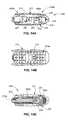
- FIGS. 12A and 12Bare perspective views of a spinal implant in accordance with another embodiment of the present disclosure.
- FIG. 13is an exploded view of the spinal implant of FIGS. 12A and 12B ;
- FIGS. 14A-14Care side, top, and cross-sectional views, respectively, of the spinal implant of FIGS. 12A-12B , in a collapsed position;
- FIG. 15is a cross-sectional view of the spinal implant of FIGS. 12A-12B , with a distal region of the spinal implant in a partially expanded position;
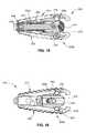
- FIG. 16is a side view of the spinal implant of FIGS. 12A-12B , with a distal region of the spinal implant in a fully expanded position;
- FIGS. 17A and 17Bare side and cross-sectional views, respectively, of the spinal implant of FIGS. 12A-12B , with proximal and distal regions of the spinal implant each in a fully expanded position;
- FIGS. 18A-18Eare perspective views of a system including the spinal implant of FIGS. 12A-12B and an insertion instrument in accordance with an embodiment of the present disclosure
- FIG. 19is a perspective view of a spinal implant in accordance with another embodiment of the present disclosure, with wing portions of the spinal implant in a retracted position;
- FIG. 20is a perspective view of the spinal implant of FIG. 19 , with the wing portions of the spinal implant in a deployed position;
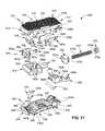
- FIG. 21is an exploded view of the spinal implant of FIG. 19 ;
- FIGS. 22A and 22Bare perspective views of an upper body and a lower body, respectively, of the spinal implant of FIG. 19 , with parts separated;
- FIGS. 23A and 23Bare end and side views, respectively, of the spinal implant of FIG. 19 , in a collapsed position;
- FIGS. 24A and 24Bare end and side views, respectively, of the spinal implant of FIGS. 23A and 23B , with the wing portions in a deployed position;
- FIGS. 25A-25Care end, side, and cut-away views, respectively, of the spinal implant of FIG. 19 , with a distal region of the spinal implant in a fully expanded position;
- FIGS. 26A-26Care end, side, and cross-sectional views, respectively, of the spinal implant of FIG. 19 , with a proximal region of the spinal implant in a fully expanded position and a distal region of the spinal implant in a partially expanded position;
- FIGS. 27A-27Care end, side, and perspective views, respectively, of the spinal implant of FIG. 19 , with proximal and distal regions of the spinal implant each in a fully expanded position.
- proximalrefers to a portion of a device or component thereof that is closer to a clinician
- distalrefers to the portion of the device or component thereof that is farther from the clinician.
- FIG. 1illustrates an expandable spinal implant or a spinal implant 100 in accordance with an embodiment of the present disclosure.
- Spinal implant 100has a proximal region 100 a and a distal region 100 b extending along a longitudinal axis “X.”
- the spinal implant 100includes an upper body 110 and a lower body 130 disposed in opposed relation relative to each other and coupled together by a proximal adjustment assembly 150 and a distal adjustment assembly 170 .
- the proximal and distal adjustment assemblies 150 , 170are independently movable to allow for adjustment in the distance between the upper and lower bodies 110 , 130 of the proximal and distal regions 100 a , 100 b of the spinal implant 100 along a transverse axis “Y.” Accordingly, the spinal implant 100 is movable between a collapsed position and a fully expanded position, and includes a number of partially expanded positions, as described in further detail below.
- the upper body 110 of the spinal implant 100includes an elongated substantially planar portion 112 having a proximal end 112 a and a distal end 112 b , and a curved portion 114 disposed distally of the distal end 112 b of the planar portion 112 .
- An outer surface 116 of the planar portion 112includes a plurality of retaining features 116 a configured to frictionally engage an adjacent surface of a vertebral body (i.e., a vertebral endplate) to maintain the position of the spinal implant 100 relative to the vertebral body and to inhibit the spinal implant 100 from backing out of the intervertebral space as the plurality of retaining features 116 may bite into the vertebral endplate.
- the plurality of retaining featuresmay be ridges, protrusions, bumps, teeth, or any other texturized structure, as is within the purview of those skilled in the art.
- An inner surface 118 of the upper body 110includes two pairs of proximal posts 120 extending from the proximal end 112 a of the planar portion 112 .
- Each proximal post 120includes a through hole 120 a defined therethrough that is aligned with the through holes 120 a of the other proximal posts 120 .
- the inner surface 118 of the upper body 110also includes a pair of distal posts 122 extending from the distal end 112 b of the planar portion 112 , proximate to the curved portion 114 .
- Each distal post 122include a through hole 122 a defined therethrough. It should be understood that the proximal and distal posts 122 that are not shown are identical to the proximal and distal posts 122 shown, and similar to the proximal and distal posts 140 and 142 of the lower body 130 .
- the lower body 130includes an elongated substantially planar portion 132 having a proximal end 132 a and a distal end 132 b , and a curved portion 134 disposed distally of the distal end 132 b of the planar portion 132 .
- the planar portion 132includes an outer surface 136 having a plurality of retaining features (not shown) disposed thereon that are configured to frictionally engage an adjacent surface of a vertebral body as discussed above with regard to the plurality of retaining features 116 a of the upper body 110 .
- An inner surface 138 of the lower body 130includes two pairs of proximal posts 140 extending from the proximal end 132 a of the planar portion 132 .
- Each proximal post 140includes a through hole 140 a defined therethrough that is aligned with the through holes 140 a of the other proximal posts 140 .
- the inner surface 138 of the lower body 130also includes a pair of distal posts 142 extending from the distal end 132 b of the planar portion 132 , proximate to the curved portion 134 .
- Each distal post 142includes a through hole 142 a defined therethrough.
- the proximal adjustment assembly 150includes a ramp 152 having a proximal wall 154 at a proximal end 152 a of the ramp 152 .
- the proximal wall 154includes a central opening 154 a (see e.g., FIG. 4A ) defined therethrough.
- a pair of upper rails 156 and a pair of lower rails 158extend distally from the proximal wall 154 towards a distal end 152 b of the ramp 152 .
- the upper and lower rails 156 , 158are inclined and taper from the proximal end 152 a to the distal end 152 b of the ramp 152 such that when viewed from the side, the ramp 132 defines a wedge shape.
- the distal end 152 b of the ramp 152includes a pair of opposed guides 160 that are configured to engage arms 186 of a bracket 174 of the distal adjustment assembly 170 , and be guided therealong.
- Each upper rail 156includes an outer surface 162 and an inner surface 164
- each lower rail 158includes an outer surface 166 and an inner surface 168 .
- the outer surfaces 162 , 166 of the upper and lower rails 156 , 158face the inner surfaces 118 , 138 of the upper and lower bodies 110 , 130 and are configured to slide relative thereto.
- the inner surfaces 164 , 168 of the upper and lower rails 156 , 158are disposed in opposed and tapering spaced relation relative to each other.
- a plurality of grooves 169extend along each of the inner surfaces 164 , 168 of the upper and lower rails 156 , 158 .
- the plurality of grooves 169may be a plurality of recesses, indentations, depressions, or the like for providing the inner surfaces 164 , 168 of the upper and lower rails 156 , 158 with an undulating surface.
- Each upper rail 156is received between a pair of the proximal posts 120 of the upper body 110 such that the through holes 120 a of the proximal posts 120 are aligned with a groove 169 of the plurality of grooves 169 extending along the inner surface 164 of the upper rails 158 .
- a first set of pins 151respectively extends through and frictionally engages a pair of the proximal posts 120 and one groove 169 of the upper rails 158 to couple the upper body 110 to the ramp 152 .
- each lower rail 158is received between a pair of the distal posts 140 of the lower body 130 such that through holes 140 a of the distal posts 140 are aligned with a groove 169 of the plurality of grooves 169 extending along the inner surface 168 of the lower rail 158 .
- a second set of pins 153respectively extends through and frictionally engages a pair of the distal posts 140 and the groove 169 of the lower rails 158 to couple the lower body 130 to the ramp 152 .
- the first and second set of pins 151 , 153are configured to ride along the plurality of grooves 169 of respective upper and lower rails 156 , 158 of the ramp 152 as the ramp 152 is moved proximally and/or distally with respect to the upper and lower bodies 110 , 130 .
- the ramp 152is mechanically coupled to the upper and lower bodies 110 , 130 and movable into and out of a space disposed between the upper and lower bodies 110 , 130 to change the distance between the upper and lower bodies 110 and 130 , and thus, the angular position and the vertical height of the spinal implant 100 about the proximal region 100 a of the spinal implant 100 .
- the distal adjustment assembly 170includes a threaded post or screw 172 , a bracket 174 , a curved plate 176 , and a pivot linkage assembly 177 including an upper pivot linkage 178 and a lower pivot linkage 180 .
- the threaded post 172includes an elongated threaded body 172 a having a proximal end 172 b configured to mate with a driver 15 of an insertion instrument 10 (see e.g., FIG. 11H ) and a flanged distal end 172 c coupled to the curved plate 176 .
- the proximal end 172 b of the threaded post 172may have a shape, such as a hex shape (not shown) for mating with the insertion instrument.
- the bracket 174includes a base plate 182 defining a threaded opening 182 a therethrough, and a boss 184 extending proximally from the base plate 182 and having a threaded opening 184 a that is coterminous with the threaded opening 182 a of the base plate 182 .
- the threaded openings 182 a and 184 a of the base plate 182 and the boss 184are configured to threadingly engage the threaded post 172 such that rotation of the threaded post 172 results in axial movement of the threaded post 172 through the bracket 174 .
- the boss 184includes a partially flanged proximal end 184 b for connection with an insertion instrument 10 (see e.g., FIG. 11A ).
- the bracket 174also includes a pair of arms 186 extending proximally from the base plate 182 that is configured to guide the ramp 152 , and a pair of legs 188 extending distally from the base plate 182 .
- the pair of legs 188includes opposed longitudinal slots 188 a and opposed holes 188 b .
- the opposed holes 188 bare disposed distally of the longitudinal slots 188 a.
- the curved plate 176includes a curved distal surface 176 a and a proximal surface 176 b having a cavity 176 c defined therein ( FIG. 10E ) that is aligned with and configured to receive and retain the flanged distal end 172 c of the threaded post 172 therein via a pin 171 .
- a pair of nubs 190extends laterally from sides of the curved plate 176 and is disposed, and longitudinally movable, within the longitudinal slots 188 a of the legs 188 of the bracket 174 .
- the pivot linkage assembly 177includes an upper pivot linkage 178 having an upper hole 178 a and a lower hole 178 b , and a lower pivot linkage 180 having a pair of upper holes 180 a and a lower hole 180 b .
- the upper hole 178 a of the upper pivot linkage 178is aligned with the through holes 122 a defined in the distal posts 122 of the upper body 110 , and a pin 155 is inserted therethrough for pivotably connecting the upper pivot linkage 178 with the upper body 110 .
- the lower hole 180 b of the lower pivot linkage 180is aligned with the through holes 142 a defined in the distal posts 142 of the lower body 130 , and a pair of pins 157 are inserted therethrough for pivotably connecting the lower pivot linkage 180 with the lower body 130 .
- the lower hole 178 b of the upper pivot linkage 178 and the upper holes 180 a of the lower pivot linkage 180are aligned with the holes 188 b in the legs 188 of the bracket 174 , and a pin 159 is disposed therethrough for pivotably securing the upper and lower bodies 110 and 130 to the bracket 174 via the upper and lower pivot linkages 178 , 180 .
- the upper and lower pivot linkages 178 , 180are coupled to the upper and lower bodies 110 , 130 , and are pivotable relative to each other about the pin 159 to change the distance between the upper and lower bodies 110 , 130 , and thus, the angular position and vertical height of the spinal implant 100 about the distal region 100 b of the spinal implant 100 .
- the proximal and distal regions 100 a and 100 b of the spinal implant 100are independently movable with respect to each other via the proximal and distal adjustment assemblies 150 , 170 so that the spinal implant 100 may have a variety of configurations.
- the independent adjustability of the proximal and distal regions 100 a , 100 b of the spinal implant 100allows a clinician to adjust the dimensions of the spinal implant 100 (i.e., vertical heights of the proximal and distal regions) such that the spinal implant 100 can be inserted between two vertebrae with relatively narrow access in the collapsed position, without force, to avoid trauma to the vertebral bodies, and in particular, the endplates of the vertebral bodies.
- proximal and/or distal regions 100 a , 100 b of the spinal implant 100can then be adjusted to partially or fully expanded positions so that the upper and lower bodies 110 , 130 are aligned with the endplates to maximize surface contact between the spinal implant 100 and the endplates, and to match the dimensions of the disc space defined between the endplates in which the spinal implant 100 is disposed.
- the adjustability of the spinal implant 100allows a clinician, for example, to minimize trauma to the vertebrae during implantation of the spinal implant 100 , to tailor the spinal implant 100 to conform to the anatomy of individual patients, to maximize contact between the spinal implant 100 and the endplates to create bone growth, to match the natural disc height of the disc space, to improve the seating of the spinal implant 100 within the disc space, and/or to lessen the likelihood of expulsion of the spinal implant 100 from the disc space.
- the spinal implant 100has a collapsed, or unexpanded, position.
- planar portions 112 , 132 of the upper and lower bodies 110 , 130are disposed in parallel relationship to each other.
- Each of the proximal and distal regions 100 a , 100 b of the spinal implant 100has a height, “h1,” that defines the minimum distance at which the upper and lower bodies 110 , 130 may be positioned relative to each other.
- height, “h1,”may range from about 2 mm to about 12 mm.
- the ramp 152is disposed in a proximalmost position such that the first and second set of pins 151 and 153 are engaged with the distalmost groove of the plurality of grooves 169 , and the curved plate 176 is disposed in a proximalmost position with the nubs 190 of the curved plate 176 disposed in a proximalmost part of the longitudinal slots 188 a of the bracket 174 such that the upper and lower pivot linkages 178 , 180 are in the collapsed position.
- the ramp 152 of the proximal adjustment assembly 150may be advanced distally between the upper and lower bodies 110 , 130 to drive the upper and lower bodies 110 , 130 apart at the proximal region 100 a of the spinal implant 100 .
- the ramp 152may be moved distally such that the first and second set of pins 151 , 153 are moved to a groove in the plurality of grooves 169 adjacent to the distalmost groove of the embodiment of FIGS. 4A-4E to partially expand the proximal region 100 a of the spinal implant 100 to a height, “h2,” to provide the spinal implant 100 with a kyphotic shape.
- each groove 169provides 1 mm of expansion at the proximal region 100 a of the spinal implant 100 .
- the grooves 169may be configured to provide different amounts of expansion based on the size and number of grooves provided in the upper and lower rails 156 , 158 of the ramp 152 .
- each groove 169may provide more or less than 1 mm of expansion and the amount of expansion for each groove 169 may not be uniform along the upper and lower rails 156 , 158 . As shown in FIGS.
- the ramp 152may be fully advanced such that the first and second set of pins 151 , 153 are moved into a proximalmost groove of the plurality of grooves 169 to achieve maximum expansion at the proximal region 100 a of the spinal implant 100 .
- the proximal wall 154 of the ramp 152is flush with the proximal ends 112 a , 132 a of the upper and lower bodies 110 , 130 .
- the distal adjustment assembly 170can be actuated by driving the threaded post 172 distally through the threaded openings 184 a , 182 a of the boss 174 and base plate 182 of the bracket 174 to push the curved plate 176 against the upper and lower pivot linkages 178 , 80 to move the upper and lower pivot linkages 178 , 180 apart.
- movement of the curved plate 176controls the displacement of the upper and lower pivot linkages 178 , 180 relative to each other.
- FIGS. 7A-7BWith the proximal region 100 a of the spinal implant 100 in the partially expanded position of FIGS. 5A-5B , rotation of the threaded post 172 in a first direction moves the threaded post 172 distally which in turn, pushes the curved plate 176 (see e.g., FIG. 10E ) distally such that the nubs 190 of the curved plate move distally within the longitudinal slots 188 a of the bracket 174 and the curved distal surface 176 a of the curved plate 176 ( FIG.
- the distal region 100 b of the spinal implant 100may be adjusted to have the same height, “h2,” as the proximal region 100 a of the spinal implant 100 such that the upper and lower bodies 110 , 130 are parallel to each other. As shown in FIGS.
- the threaded post 172may be fully advanced such that the nubs 190 of the curved plate 176 are disposed in a distalmost portion of the longitudinal slots 188 a of the bracket 174 to achieve maximum expansion at the distal region 100 b , to a height, “h4,” of the spinal implant 100 .
- the height, “h3,”may range from about 3 mm to about 13 mm
- the height, “h4,”may range from about 8 mm to about 18 mm.
- the threaded post 172is moved a distance axially such that the distal region 100 b of the spinal implant 100 is adjusted to have the same height as the proximal region 100 a of the spinal implant 100 .
- the distal adjustment assembly 170is shown in a fully expanded position to achieve maximum expansion of both the proximal and distal regions 100 a , 100 b of the spinal implant 100 .
- proximal and distal regions of the spinal implantmay be independently adjusted to achieve a desired configuration of the spinal implant. Accordingly, it is contemplated that only the proximal region or the distal region of the spinal implant may be expanded, should that be a desired configuration, or both the proximal and distal regions of the spinal implant may be expanded to achieve a desired configuration (e.g., an implant having a kyphotic shape, a lordotic shape, etc.).
- FIGS. 11A-11Ja method for inserting, positioning, and/or adjusting (e.g., expanding) the spinal implant 100 in an interdisc space between adjacent vertebral bodies with an insertion instrument 10 is shown.
- a tip 11 of the insertion instrument 10is aligned with the proximal region 100 a of the spinal implant 100 disposed in the collapsed position.
- the tip 11 of the insertion instrument 10is placed into the spinal implant 100 through the central opening 154 a of the proximal wall 154 of the ramp 152 , between the upper and lower bodies 110 and 130 of the spinal implant 100 , and over the boss 184 of the bracket 174 (see e.g., FIG.
- the insertion instrument 10is rotated 90 degrees so that the tip 11 engages the partially flanged proximal end 184 b of the boss 184 (see e.g., FIG. 3D ) for releasable attachment of the insertion instrument 10 to the spinal implant 100 .
- FIGS. 11Cthe insertion instrument 10 is rotated 90 degrees so that the tip 11 engages the partially flanged proximal end 184 b of the boss 184 (see e.g., FIG. 3D ) for releasable attachment of the insertion instrument 10 to the spinal implant 100 .
- handles 12 of the insertion instrument 10may be squeezed and/or a thumb wheel 13 of the insertion instrument 10 may be rotated to advance the tip 11 of the insertion instrument 10 distally into the ramp 152 such that a flanged portion 14 of the insertion instrument 10 abuts the proximal wall 154 of the ramp 152 to push the ramp 152 between the upper and lower bodies 110 and 130 and thus, expand the proximal region 100 a of the spinal implant 100 as shown in FIGS. 11F and 11G .
- a driver 15is inserted through the insertion instrument 10 and includes a shaped distal end 16 configured to engage the proximal end 172 b of the threaded post 172 (see e.g., FIG. 2 ) of the spinal implant 100 .
- the threaded post 172is also rotated and moved distally against the curved plate 176 thereby moving the curved plate 176 into the upper and lower pivot linkages 178 and 180 (see e.g., FIG. 2 ) to expand the distal region 100 b of the spinal implant 100 , as shown in FIG. 11J .
- the insertion instrument 10may be advanced and/or the driver 15 may be rotated to expand the proximal and/or distal regions 100 a , 100 b of the spinal implant 100 to any desired position.
- a clinicianremoves all or a portion of a disc from between two vertebral bodies (e.g., complete or partial diskectomy), and scrapes and cleans the endplates of the vertebral bodies to prepare the surfaces for placement of the spinal implant 100 such that a fusion will occur.
- the clinicianplaces the spinal implant 100 into the disc space using the insertion instrument 10 .
- the insertion instrument 10is attached to the implant by inserting the tip 11 of the insertion instrument 10 over the boss 184 of the bracket 174 and rotating the insertion instrument 10 ninety (90) degrees to engage the partially flanged proximal end 184 b of the boss 184 , as described above.
- the insertion instrument 10may be pre-attached to the spinal implant 100 prior to inserting the spinal implant 100 into the disc space, or may be attached after the spinal implant 100 is positioned in the disc space.
- the handles 12 and/or the thumb wheel 13 of the insertion instrument 10is actuated to drive the ramp 152 distally into the spinal implant 100 and thus increase the proximal height of the spinal implant 100 in discrete increments (e.g., 1 mm increments) as the first and second set of pins 151 , 153 advance distally into grooves 169 of the respective upper and lower rails 156 , 158 .
- Various allograft and/or autograft materialsmay be placed into and/or next to the spinal implant 100 to assist in the fusion process.
- the driver 15would be re-engaged with the threaded post 172 and rotated in a second direction (e.g., counter-clockwise) to drive the threaded post 172 proximally.
- a separate instrument(not shown) would be utilized to move the upper and lower bodies 110 and 130 away from the ramp 152 .
- FIGS. 12A and 12Ban expandable spinal implant or spinal implant 200 in accordance with another embodiment of the present disclosure is shown.
- the spinal implant 200is similar to the spinal implant 100 and therefore will be described with respect to the differences therebetween.
- the spinal implant 200has a proximal region 200 a and a distal region 200 b , and includes an upper body 210 and a lower body 230 disposed in opposed relation relative to each other and coupled together by a proximal adjustment assembly 250 and a distal adjustment assembly 270 .
- the proximal and distal adjustment assemblies 250 and 270are independently movable to allow for adjustment in the angular and vertical distance between the upper and lower bodies 210 , 230 of the proximal and distal regions 200 a , 200 b of the spinal implant 200 .
- the independent adjustability of the proximal and distal regions 200 a , 200 b of the spinal implant 200allows a clinician to adjust the dimensions of the spinal implant 200 (i.e., vertical heights of the proximal and distal regions) such that the spinal implant 200 can be inserted between two vertebrae with relatively narrow access in the collapsed position, without force, to avoid trauma to the vertebral bodies, and in particular, the endplates of the vertebral bodies.
- the proximal and/or distal regions 200 a , 200 b of the spinal implant 200can then be adjusted to partially or fully expanded positions so that the upper and lower bodies 210 , 230 are aligned with the endplates to maximize surface contact between the spinal implant 200 and the endplates, and to match the dimensions of the disc space defined between the endplates of the vertebral bodies in which the spinal implant 200 is disposed.
- the adjustability of the spinal implant 200allows a clinician, for example, to minimize trauma to the vertebrae during implantation of the spinal implant 200 , to tailor the spinal implant 200 to conform to the anatomy of individual patients, to maximize contact between the spinal implant 200 and the endplates to create bone growth, to match the natural disc height of the disc space, to improve the seating of the spinal implant 200 within the disc space, and/or to lessen the likelihood of expulsion of the spinal implant 200 from the disc space.
- the upper body 210 of the spinal implant 200includes an elongated substantially planar portion 212 and a curved portion 214 disposed distally of the planar portion 212 .
- An outer surface 216 of the planar portion 212includes a plurality of retaining features 216 a .
- An inner surface 218 of the upper body 210includes a pair of proximal fins 220 and a pair of distal posts 222 .
- Each proximal fin 220includes an angled slot 220 a and a vertical slot 220 b defined therein.
- the angled slot 220 ais disposed proximal to the vertical slot 220 b .
- Each distal post 222includes a through hole 222 a defined therethrough.
- the lower body 230includes an elongated substantially planar portion 232 and a curved portion 234 disposed distally of the planar portion 232 .
- the planar portion 232includes an outer surface 236 having a plurality of retaining features 236 a disposed thereon.
- An inner surface 238 of the lower body 230includes a pair of proximal fins 240 and a pair of distal posts 242 .
- Each proximal fin 240includes an angled slot 240 a and a vertical slot 240 b defined therein.
- Each distal post 242includes a through hole 242 a defined therethrough.
- the proximal adjustment assembly 250includes, a linkage body 252 , a flange nut 254 disposed proximally of the linkage body 252 , and a coupler 256 disposed distally of the linkage body 252 .
- the linkage body 252includes a central opening 252 a defined therethrough, and a recess 252 b defined in a proximal portion of the linkage body 252 between a pair of arms 258 extending along lateral sides of the linkage body 252 .
- the arms 258include proximal holes 258 a that are dimensioned to engage an insertion instrument 20 (see e.g. FIG.
- a first set of pins 251respectively extends through and frictionally engages the distal hole 258 b and the angled slots 220 a , 240 a of the proximal fins 220 , 240 of the upper and lower bodies 210 , 230 to adjustably couple the upper and lower bodies 210 , 230 together via the linkage body 252 .
- the first set of pins 251is configured to ride along the angled slots 220 a , 240 a of the proximal fins 220 , 240 of the upper and lower bodies 210 , 230 as the linkage body 252 is moved proximally and/or distally within the upper and lower bodies 210 , 230 .
- the coupler 256includes a central opening 256 a defined therein that has the same size and shape as the central opening 252 a of the linkage body 252 .
- the central openings 252 a and 256 a of the linkage body 252 and the coupler 256are sized and shaped to engage, and be supported on, a shaft 282 of an expander 274 of the distal adjustment assembly 270 .
- the coupler 256also includes a pair of nubs 260 having flanged outer ends 260 a extending laterally from sides thereof that are dimensioned to be retained and slide within the vertical slots 220 b , 240 b of the proximal fins 220 , 240 of the upper and lower bodies 210 , 230 .
- the flange nut 254includes a body portion 254 a having a flanged distal end 254 b and a threaded opening 254 c defined therethrough that is configured to threadingly engage a threaded post 272 of the distal adjustment assembly 270 and be rotated and axially translated along the threaded post 272 .
- the flanged distal end 254 b of the flange nut 254is dimensioned to be received within the recess 252 b of the linkage body 252 .
- movement of the flange nut 254distally moves the linkage body 252 distally causing the first set of pins 251 to translate within the angled slots 220 a , 240 a of the proximal fins 220 , 240 and the nubs 260 of the coupler 256 to translate within the vertical slots 220 b , 240 b of the proximal fins 220 , 240 to increase the distance between the upper and lower bodies 210 and 230 at the proximal region 200 a of the spinal implant 200 .
- movement of the flange nut 254proximally moves the linkage body 252 proximally to reduce the distance between the upper and lower bodies 210 , 230 at the proximal region 200 a of the spinal implant 200 .
- the distal adjustment assembly 270includes a threaded post 272 , an expander 274 , and a pivot linkage assembly 275 (see e.g., FIG. 15 ) including an upper pivot linkage 276 and a lower pivot linkage 278 .
- the threaded post 272includes an elongated threaded body 272 a having a hex-shaped proximal end 272 b (see e.g., FIG. 12B ) configured to mate with a driver 23 of an insertion instrument 20 (see e.g., FIG. 18D ) and a distal end 272 c .
- the expander 274includes a body portion 280 defining a cavity 280 a therein.
- a pair of opposed longitudinal slots 280 bis disposed on lateral sides of the body portion 280 , and a distal end of the body portion 280 includes a double ramped inner surface 280 c (see e.g., FIG. 14C ).
- a shaft 282extends proximally from the body portion 280 of the expander 274 and defines a threaded opening 282 a therethrough that is configured to receive the threaded post 272 .
- the pivot linkage assembly 275includes an upper pivot linkage 276 having an upper hole 276 a and a lower hole 276 b , and a lower pivot linkage 278 having an upper hole 278 a and a lower hole 278 b .
- the upper hole 276 a of the upper pivot linkage 276is aligned with the through holes 222 a defined in the distal posts 222 of the upper body 210 , and a second set of pins 252 is inserted therethrough for pivotably connecting the upper pivot linkage 276 with the upper body 210 .
- the lower hole 278 b of the lower pivot linkage 278is aligned with the through holes 242 a defined in the distal posts 242 of the lower body 230 , and a pin 255 is inserted therethrough for pivotably connecting the lower pivot linkage 278 with the lower body 230 .
- the lower hole 276 b of the upper pivot linkage 276 and the upper hole 278 a of the lower pivot linkage 278are aligned with each other and with the longitudinal slots 280 b defined in the expander 274 such that the upper and lower pivot linkages 276 and 278 are disposed within the cavity 280 a in the body portion 280 of the expander 274 , and a pin 257 is disposed therethrough for pivotably securing the upper and lower bodies 210 and 230 to the expander 274 of the distal adjustment assembly 270 via the upper and lower pivot linkages 276 , 278 .
- This arrangementallows for simultaneous translation of the pin 257 within the longitudinal slots 280 b of the expander 274 and pivoting movement of the upper and lower pivot linkages 276 , 278 .
- the threaded post 272is rotated in a first direction to advance the threaded post 272 distally until it pushes against and drives the upper and lower pivot linkages 276 , 278 against the double ramped inner surface 280 c of the expander 274 thereby increasing the height between the upper and lower bodies 210 , 230 at the distal region 200 b of the spinal implant 200 .
- Rotation of the threaded post 272 in a second, reverse directionmoves the threaded post 272 proximally to allow the upper and lower pivot linkages 276 , 278 to collapse, thereby decreasing the height between the upper and lower bodies 210 , 230 at the distal region 200 b of the spinal implant 200 .
- the spinal implant 200has a collapsed, or unexpanded, position.
- the planar portions 212 , 232 of the upper and lower bodies 210 , 230are disposed in parallel relationship to each other.
- the first set of pins 251 of the linkage body 252 and the nubs 260 of the coupler 256are disposed within the angled slots 220 a , 240 a and the vertical slots 220 b , 240 b , respectively, of the proximal fins 220 , 240 of the upper and lower bodies 210 , 230 such that the nubs 260 rest within an uppermost portion of the vertical slot 220 a of the upper body 210 and a lowermost portion of the vertical slot 240 b of the lower body 230 .
- the pin 257 disposed through the expander 274 and the upper and lower pivot linkages 276 , 278is disposed in a proximalmost position within the longitudinal slots 280 b of the expander 274 so that the upper and lower pivot linkages 276 , 278 are in the collapsed position.
- rotation of the threaded post 272 in a first directionmoves the threaded post 272 distally through the threaded opening 254 c of the flange nut 254 and the threaded opening 282 a of the shaft 282 of the expander 274 which, in turn, pushes the upper and lower pivot linkages 176 , 178 into the double ramped inner surface 280 c of the expander 274 to change the distance between the upper and lower bodies 210 , 230 about the distal region 200 b of the spinal implant 200 .
- Continued rotation of the threaded post 272 in the distal directioncauses the upper and lower pivot linkages 276 , 278 to move into a fully expanded position, as shown in FIG. 16 .
- the pin 257is disposed in a distalmost position within the longitudinal slot 280 b of the expander 274 .
- the flange nut 254 of the proximal adjustment assembly 250may be advanced distally between the upper and lower bodies 210 , 230 to drive the upper and lower bodies 210 , 230 apart at the proximal region 200 a of the spinal implant 200 , as shown in FIGS. 17A-17B .
- Rotation of the flange nut 254 in a first directionmoves the flange nut 254 and the linkage body 252 distally such that the first set of pins 251 slide within the angled slots 220 a , 240 a of the proximal fins 220 , 240 of the upper and lower bodies 210 and 230 , and the nubs 260 of the coupler 256 slide within the vertical slots 220 b , 240 b to partially or fully expand the proximal region 200 a of the spinal implant 200 .
- the proximal region 200 a of the spinal implant 200is fully expanded when the nubs 260 of the coupler 256 are disposed within a lowermost portion of the vertical slot 220 a of the upper body 210 and an uppermost portion of the vertical slot 240 b of the lower body 230 . While the distal region 200 b of the spinal implant 200 is shown in the fully expanded position of FIG. 16 , it should be understood that the distal region 200 b may have any desired configuration.
- the spinal implant 200 and an insertion instrument 20are shown.
- the insertion instrument 20includes feet 21 disposed at a distal end thereof that are configured to engage the proximal through holes 258 a of the linkage body 252 of the spinal implant 200 .
- the insertion instrument 20includes hinges 22 that allow the feet 21 to flex for releasable positioning of the feet 21 into the proximal through holes 258 a of the spinal implant 200 .
- FIGS. 18A-18Ethe spinal implant 200 and an insertion instrument 20 are shown.
- a driver 23is inserted through an opening 20 a of the insertion instrument 20 , and includes a shaped distal end 24 , such as a hex portion, configured to make with the hex-shaped proximal end 272 b of the threaded post 272 .
- a handle 25 of the driver 23is rotated in a first or second direction to rotate the threaded post 272 which, in turn, moves the threaded post 272 distally or proximally to adjust the height of the distal region 200 b of the spinal implant 200 .
- a thumb wheel 26 of the insertion instrument 20is rotated in a first or second direction to rotate the flange nut 254 which, in turn, moves the flange nut 254 distally or proximally to adjust the height of the proximal region 200 a of the spinal implant 200 .
- a clinicianremoves all or a portion of a disc from between two vertebral bodies (e.g., complete or partial diskectomy) and cleans the end plates of the vertebral bodies, as discussed above.
- the clinicianthen places the spinal implant 200 into the disc space using the insertion instrument 20 , and may adjust the height of the proximal and/or distal regions 200 a and 200 b of the spinal implant 200 as described above.
- Various allograft and/or autograft materialsmay be used to assist in the fusion process.
- FIGS. 19 and 20an expandable spinal implant or spinal implant 300 in accordance with another embodiment of the present disclosure is shown.
- the spinal implant 300is similar to spinal implants 100 and 200 , and thus will be described with respect to the differences therebetween.
- the spinal implant 300has a proximal region 300 a and a distal region 300 b , and includes an upper body 310 and a lower body 330 disposed in opposed relation relative to each other and coupled together by a proximal adjustment assembly 350 and a distal adjustment assembly 370 .
- the proximal and distal adjustment assemblies 350 and 370are independently movable to allow for adjustment in the angular and vertical distance between the upper and lower bodies 310 and 330 of the proximal and distal regions 300 a and 300 b of the spinal implant 300 .
- the independent adjustability of the proximal and distal regions 300 a , 300 b of the spinal implant 300allows a clinician to adjust the dimensions of the spinal implant 300 (i.e., vertical heights of the proximal and distal regions) such that the spinal implant 300 can be inserted between two vertebrae with relatively narrow access in the collapsed position, without force, to avoid trauma to the vertebral bodies, and in particular, the endplates of the vertebral bodies.
- the proximal and/or distal regions 300 a , 300 b of the spinal implant 300can then be adjusted to partially or fully expanded positions so that the upper and lower bodies 310 , 330 are aligned with the endplates to maximize surface contact between the spinal implant 300 and the endplates, and to match the dimensions of the disc space defined between the endplates of the vertebral bodies in which the spinal implant 300 is disposed.
- the adjustability of the spinal implant 300allows a clinician, for example, to minimize trauma to the vertebrae during implantation of the spinal implant 300 , to tailor the spinal implant 300 to conform to the anatomy of individual patients, to maximize contact between the spinal implant 300 and the endplates to create bone growth, to match the natural disc height of the disc space, to improve the seating of the spinal implant 300 within the disc space, and/or to lessen the likelihood of expulsion of the spinal implant 300 from the disc space.
- the upper body 310 of the spinal implant 300includes an elongated substantially planar portion 312 and a curved portion 314 disposed distally of the planar portion 312 .
- the planar portion 312is a two-piece construction including an outer surface 316 and a wing portion 318 disposed over the outer surface 316 .
- the outer surface 316includes a plurality of retaining features 316 a and a central recess 316 b including an opening 316 c defined therein.
- the wing portion 318includes an elongated body 318 a including an outer surface 318 b including a plurality of retaining features 316 a , and an inner surface 318 c including a flange (not shown) extending therefrom that is dimensioned to be received and retained within the opening 316 c of the outer surface 316 (e.g., the flange may be swaged or rolled into securement with upper body 310 to prevent separation of the wing portion 318 from the outer surface 316 of the upper body 310 ).
- the wing portion 318is movable from a first, retracted position in which the wing portion 318 is aligned with the outer surface 316 of the upper body 310 (see e.g., FIG. 19 ) and a second, deployed position in which the wing portion 318 is turned or rotated 90 degrees and disposed within the central recess 316 b defined in the outer surface 316 of the upper body 310 (see e.g., FIG. 20 ) such that the wing portion 318 is flush with the outer surface 316 to increase the surface area and footprint of the outer surface 316 of the upper body 310 .
- planar portion 312 of the upper body 310may be a one piece construction, as shown, for example in the embodiments of spinal implants 100 and 200 .
- Angled slots 320 aare disposed in a proximal portion of side surfaces 320 of the upper body 310 , and rib features 322 extends from the side surface 320 to strengthen the upper body 310 .
- An inner surface 324 of the upper body 310includes a pair of distal posts 326 each including a through hole 326 a defined therethrough.
- the lower body 330 of the spinal implant 300includes an elongated substantially planar portion 332 and a curved portion 334 disposed distal to the planar portion 332 .
- the planar portion 332is a two-piece construction including an outer surface 336 and a wing portion 338 disposed over the outer surface 336 .
- the outer surface 336includes a plurality of retaining features 336 a and a central recess 336 b including an opening 336 c defined therein.
- the wing portion 338includes an elongated body 338 a including an outer surface 338 b including a plurality of retaining features 336 a , and an inner surface 338 c including a flange 338 d extending therefrom that is dimensioned to be received within the opening 336 c of the outer surface 336 , as described above with respect to the wing portion 318 of the upper body 310 .
- the wing portion 338is movable from a first, retracted position in which the wing portion 338 is aligned with the outer surface 336 of the lower body 330 (see e.g., FIG. 19 ) and a second, deployed position in which the wing portion 338 is turned 90 degrees and disposed within the central recess 336 b defined in the outer surface 336 of the lower body 330 (see e.g., FIG. 20 ) such that the wing portion 338 is flush with the outer surface 336 to increase the surface area and footprint of outer surface 336 of the lower body 330 .
- the planar portion 332 of the lower body 330may be a one piece construction, as shown, for example in the embodiments of spinal implants 100 and 200 .
- An inner surface 340 of the lower body 330includes a pair of proximal fins 342 including angled slots 342 a defined therethrough, and a pair of distal posts 344 each including a through hole 344 a defined therethrough. Rib features 346 extend from lateral sides of the lower body 330 to strengthen the lower body 330 .
- the proximal adjustment assembly 350includes a plug 352 , a nut 354 disposed distal to the plug 352 , and a bracket assembly 355 including first and second bracket bodies 356 a , 356 b , and first and second bracket arms 358 a , 358 b .
- the plug 352includes a central opening 352 a defined therethrough that is configured to engaged and slide relative to a shaft 382 of an expander 374 of the distal adjustment assembly 370 .
- the first bracket body 356 ahas an L-shape and includes a plate 360 having an opening 360 a defined therethrough, and an extension 362 extending proximally therefrom that includes an opening 362 a defined therethrough and a proximal nub 362 b extending from an inner surface 362 c of the extension 362 .
- the second bracket body 356 balso has an L-shape and includes a pair of spaced plates 364 having openings 364 a defined therethrough, and an extension 366 extending proximally therefrom that includes an opening 366 a defined therethrough and a proximal nub 366 b extending from an inner surface 366 c of the extension 366 .
- the plate 360 of the first bracket body 356 ais received between the plates 364 of the second bracket body 356 b such that the openings 360 a and 364 a are aligned and slidably engaged with the shaft 382 of the expander 374 of the distal adjustment assembly 370 .
- the first and second bracket arm 358 a , 358 binclude outer surfaces 368 each including a distal boss 368 a and a proximal nub 368 b .
- the distal bosses 368 a of the first and second bracket arms 358 a , 358 bare dimensioned to be received and retaining within the openings 362 a , 366 a of respective extensions 362 , 366 of the first and second bracket bodies 356 a , 356 b .
- the proximal nubs 368 a of the first and second bracket arms 358 a and 358 bare dimensioned to be received and slidably retained within the angled slots 320 a of the upper body 310
- the proximal nubs 362 b , 366 b of the extensions 362 , 366 of the first and second bracket bodies 356 a , 356 bare dimensioned to be received and slidably retained within the angled slots 342 a defined in the proximal fins 342 of the lower body 330 .
- the upper and lower bodies 310 , 330are coupled together via the bracket assembly 355 of the proximal adjustment assembly 350 .
- the nut 354includes a threaded opening 354 a that is configured to threadingly engage a threaded post 372 of the distal adjustment assembly 370 , and be rotated and axially translated along the threaded post 372 . Accordingly, distal movement of the nut 354 pushes and slides the plug 352 and the bracket assembly 355 distally along the shaft 382 of the expander 374 which, in turn, slides the proximal nubs 368 b disposed within the angled slots 320 a of the upper body 310 , and the proximal nubs 362 b , 366 b disposed within the angled slots 342 a of the lower body 330 , to increase the distance between the upper and lower bodies 310 and 330 at the proximal region 300 a of the spinal implant 300 .
- the distal adjustment assembly 370includes a threaded post 372 , an expander 374 , and a pivot linkage assembly 375 (see e.g., FIG. 25C ) including an upper pivot linkage 376 and a lower pivot linkage 378 .
- the threaded post 372includes an elongated threaded body 372 a having a shaped proximal end 372 b (see e.g., FIG. 26C ) configured to mate with an insertion instrument (not shown) and a distal end 372 c .
- the expander 374includes a body portion 380 defining a cavity 380 a therein.
- a pair of opposed longitudinal slots 380 bare disposed on lateral sides of the body portion 380 , and a distal end of the body portion 380 includes a double ramped inner surface 380 c (see e.g., FIG. 26C ).
- a shaft 382extends proximally from the body portion 380 and defines a threaded opening 382 a therethrough that is configured to receive the threaded post 372 .
- the pivot linkage assembly 375includes an upper pivot linkage 376 having an upper hole 376 a and a lower hole 376 b , and a lower pivot linkage 378 having an upper hole 378 a and a lower hole 378 b .
- the upper hole 376 a of the upper pivot linkage 376is aligned with the through holes 326 a defined in the distal posts 326 of the upper body 310 , and a first set of pins 351 are inserted therethrough for pivotably connecting the upper pivot linkage 376 with the upper body 310 .
- the lower hole 378 b of the lower pivot linkage 378is aligned with the through holes 344 a defined in the distal posts 344 of the lower body 330 , and a pin 353 is inserted therethrough for pivotably connecting the lower pivot linkage 378 with the lower body 330 .
- the lower hole 376 b of the upper pivot linkage 376 and the upper hole 378 a of the lower pivot linkage 378are aligned with the longitudinal slots 380 b defined in the expander 374 such that the upper and lower pivot linkages 376 and 378 are disposed within the cavity 380 a in the body portion 380 of the expander 374 , and a pin 357 is disposed therethrough for pivotably securing the upper and lower bodies 310 and 330 to the expander 374 of the distal adjustment assembly 370 via the upper and lower pivot linkages 376 and 378 .
- the threaded post 372is advanced distally through the threaded opening 382 a of the shaft 382 of the expander 374 , and into the cavity 380 a defined in the body portion 380 of the expander 374 until it contacts and pushes the upper and lower pivot linkages 376 , 378 against the double ramped inner surface 380 c of the expander 374 thereby increasing the height between the upper and lower bodies 310 , 330 at the distal region 300 b of the spinal implant 300 . Movement of the threaded post 372 in a reverse direction allows the upper and lower pivot linkages 376 , 378 to collapse, thereby decreasing the height between the upper and lower bodies 310 , 330 at the distal region 300 b of the spinal implant 300 .
- the spinal implant 300has a collapsed, or unexpanded, position.
- the planar portions 312 , 332 of the upper and lower bodies 310 , 330are disposed in parallel relationship to each other.
- Each of the proximal and distal regions 300 a , 300 b of the spinal implant 300has a height, “h5,” that defines the minimum distance at which the upper and lower bodies 310 , 330 may be positioned relative to each other, and each of the wing portions 318 , 338 has a height, “h6,” that defines the minimum distance at which the wing portions 318 , 338 may be positioned relative to each other when in the retracted position.
- the height, “h5,”may range from about 2.5 mm to about 12.5 mm, and the height, “h6,” may range from about 4 mm to about 14 mm.
- the proximal nubs 368 b of the bracket arms 358 a , 358 bare disposed within an uppermost portion of the angled slots 320 a of the upper body 310 and the proximal nubs 362 b , 366 b of the bracket bodies 356 a , 356 b are disposed within a lowermost portion of the angled slots 342 a of the lower body 330 .
- the pin 357 disposed through the expander 374 and the upper and lower pivot linkages 376 and 378is disposed in a proximalmost position within the longitudinal slots 380 b of the expander 374 so that the upper and lower pivot linkages 376 and 378 are in the collapsed position.
- the wing portions 318 , 338 of the upper and lower bodies 310 , 330are in the retracted position such that the spinal implant 300 has an unexpanded width, “w1,” and in the embodiment of FIGS. 24A and 24B , the wing portions 318 , 338 of the upper and lower bodies 310 , 330 are in the deployed position, such that the spinal implant 300 has an expanded width, “w2.”
- the width, “w1,”may range from about 9 mm to about 19 mm
- the width, “w2”may range from about 22 mm to about 32 mm. Accordingly, in the retracted position, the spinal implant 300 has an increased overall height and a decreased width compared to the deployed position.
- the wing portions 318 , 338may be deployed independently or at the same time and/or may be deployed at varying angles with respect to the upper and lower bodies 310 and 330 .
- the wing portions 318 , 338are deployed manually after insertion of the spinal implant 300 into a disc space, however, it is contemplated that the wing portions 318 , 338 may be deployed manually prior to insertion of the spinal implant 300 into the disc space.
- the wing portions 318 , 338may be deployed with the use of a tether or the like and then reversed back into alignment with the upper and lower bodies 310 , 330 .
- the upper and lower pivot linkages 376 and 378move into a fully expanded position in which the distal region 300 b has a height, “h8,” that forms an acute angle, “ ⁇ 1,” with respect to a plane extending along the upper or lower body 310 , 330 .
- the height, “h7,”may range from about 2 mm to about 12 mm
- the height, “h8,”may range from about 9 mm to about 19 mm
- the angle, “ ⁇ 1”may range from about 8° to about 18°.
- the pin 357is disposed in a distalmost position within the longitudinal slot 380 b of the expander 374 .
- the distal region 300 b of the spinal implant 300is shown in a partially expanded position due to rotation of the threaded post 372 , as described above.
- the proximal region 300 a of the spinal implant 300is also partially expanded by rotating the nut 354 distally along the threaded post 372 such that the nut 354 abuts the plug 352 and pushes the plug 352 into the bracket assembly 355 thereby sliding the nubs 368 b in the angled slots 320 a of the upper body 310 and the nubs 362 b and 366 b in the angled slots 342 a of the lower body 330 , causing the upper and lower bodies 310 and 330 to move apart about the proximal region 330 a of the spinal implant 300 .
- the proximal and distal regions 300 a and 300 bare shown as having the same height, “h9.” In embodiments, the height, “h9,” may range from about 5.5 mm to about 15.5 mm. It should be understood that the proximal and distal regions 300 a and 300 b may be adjusted alone or in combinations of the same or different heights. As shown in FIGS. 27A-27C , the proximal region 300 a of the spinal implant 300 is fully expanded to a height, “h10,” and the distal region 300 b of the spinal implant 300 is fully expanded to a height, “h11,” such that the spinal implant 300 has a lordotic shape.
- the height, “h10,”may range from about 5 mm to about 15 mm, and the height “h11,” may range from about 9 mm to about 19 mm.
- the angle, “ ⁇ 2,” defined at the distal region 300 b of the spinal implant 300may range from about 1° to about 11°.
- a clinicianremove all or a portion of the disc from between the two vertebral bodies (e.g., complete or partial diskectomy) and cleans the endplates of the vertebral bodies, as discussed above.
- the clinicianplaces the implant 300 into the disc space using an insertion instrument (not shown).
- the wing portionsmay be deployed depending on surgical need.
- Various allograft and/or autograft materialsmay be used to assist in the fusion process. Should the clinician need to adjust the height of the implant 300 after it is inserted between the vertebrae, the proximal and/or distal heights can be adjusted independently, as discussed above with respect to spinal implants 100 , 200 .
Landscapes
- Health & Medical Sciences (AREA)
- Engineering & Computer Science (AREA)
- Biomedical Technology (AREA)
- Orthopedic Medicine & Surgery (AREA)
- Neurology (AREA)
- Vascular Medicine (AREA)
- Transplantation (AREA)
- Heart & Thoracic Surgery (AREA)
- Oral & Maxillofacial Surgery (AREA)
- Life Sciences & Earth Sciences (AREA)
- Animal Behavior & Ethology (AREA)
- General Health & Medical Sciences (AREA)
- Public Health (AREA)
- Veterinary Medicine (AREA)
- Cardiology (AREA)
- Prostheses (AREA)
Abstract
Description
Claims (7)
Priority Applications (6)
| Application Number | Priority Date | Filing Date | Title |
|---|---|---|---|
| US14/965,246US10363142B2 (en) | 2014-12-11 | 2015-12-10 | Expandable spinal implants |
| AU2015268677AAU2015268677B2 (en) | 2014-12-11 | 2015-12-11 | Expandable spinal implants |
| EP15199537.0AEP3031424B1 (en) | 2014-12-11 | 2015-12-11 | Expandable spinal implants |
| US16/516,702US11331200B2 (en) | 2014-12-11 | 2019-07-19 | Expandable spinal implants |
| AU2020233698AAU2020233698B2 (en) | 2014-12-11 | 2020-09-16 | Expandable spinal implants |
| US17/731,899US12257159B2 (en) | 2014-12-11 | 2022-04-28 | Expandable spinal implants |
Applications Claiming Priority (4)
| Application Number | Priority Date | Filing Date | Title |
|---|---|---|---|
| US201462090429P | 2014-12-11 | 2014-12-11 | |
| US201562158470P | 2015-05-07 | 2015-05-07 | |
| US201562206779P | 2015-08-18 | 2015-08-18 | |
| US14/965,246US10363142B2 (en) | 2014-12-11 | 2015-12-10 | Expandable spinal implants |
Related Child Applications (1)
| Application Number | Title | Priority Date | Filing Date |
|---|---|---|---|
| US16/516,702ContinuationUS11331200B2 (en) | 2014-12-11 | 2019-07-19 | Expandable spinal implants |
Publications (2)
| Publication Number | Publication Date |
|---|---|
| US20160166396A1 US20160166396A1 (en) | 2016-06-16 |
| US10363142B2true US10363142B2 (en) | 2019-07-30 |
Family
ID=54849541
Family Applications (3)
| Application Number | Title | Priority Date | Filing Date |
|---|---|---|---|
| US14/965,246Active2036-06-05US10363142B2 (en) | 2014-12-11 | 2015-12-10 | Expandable spinal implants |
| US16/516,702Active2036-08-06US11331200B2 (en) | 2014-12-11 | 2019-07-19 | Expandable spinal implants |
| US17/731,899Active2036-12-27US12257159B2 (en) | 2014-12-11 | 2022-04-28 | Expandable spinal implants |
Family Applications After (2)
| Application Number | Title | Priority Date | Filing Date |
|---|---|---|---|
| US16/516,702Active2036-08-06US11331200B2 (en) | 2014-12-11 | 2019-07-19 | Expandable spinal implants |
| US17/731,899Active2036-12-27US12257159B2 (en) | 2014-12-11 | 2022-04-28 | Expandable spinal implants |
Country Status (3)
| Country | Link |
|---|---|
| US (3) | US10363142B2 (en) |
| EP (1) | EP3031424B1 (en) |
| AU (2) | AU2015268677B2 (en) |
Cited By (46)
| Publication number | Priority date | Publication date | Assignee | Title |
|---|---|---|---|---|
| US20170367845A1 (en)* | 2016-06-28 | 2017-12-28 | Eit Emerging Implant Technologies Gmbh | Expandable and angularly adjustable articulating intervertebral cages |
| US20190021870A1 (en)* | 2014-04-01 | 2019-01-24 | Ex Technology, Llc | Expandable Intervertebral cage |
| US11253372B2 (en)* | 2019-03-09 | 2022-02-22 | Iorthopedics, Inc. | Universally expanding cages |
| US11285014B1 (en) | 2020-11-05 | 2022-03-29 | Warsaw Orthopedic, Inc. | Expandable inter-body device, system, and method |
| US11291554B1 (en) | 2021-05-03 | 2022-04-05 | Medtronic, Inc. | Unibody dual expanding interbody implant |
| US11344424B2 (en) | 2017-06-14 | 2022-05-31 | Medos International Sarl | Expandable intervertebral implant and related methods |
| US11376134B1 (en) | 2020-11-05 | 2022-07-05 | Warsaw Orthopedic, Inc. | Dual expanding spinal implant, system, and method of use |
| US11395743B1 (en) | 2021-05-04 | 2022-07-26 | Warsaw Orthopedic, Inc. | Externally driven expandable interbody and related methods |
| US11426286B2 (en) | 2020-03-06 | 2022-08-30 | Eit Emerging Implant Technologies Gmbh | Expandable intervertebral implant |
| US11426290B2 (en) | 2015-03-06 | 2022-08-30 | DePuy Synthes Products, Inc. | Expandable intervertebral implant, system, kit and method |
| WO2022187102A1 (en)* | 2021-03-03 | 2022-09-09 | Aurora Spine, Inc. | Body density scan result-matched orthopedic implants and methods of use |
| US11446155B2 (en) | 2017-05-08 | 2022-09-20 | Medos International Sarl | Expandable cage |
| US11446156B2 (en) | 2018-10-25 | 2022-09-20 | Medos International Sarl | Expandable intervertebral implant, inserter instrument, and related methods |
| US11510788B2 (en) | 2016-06-28 | 2022-11-29 | Eit Emerging Implant Technologies Gmbh | Expandable, angularly adjustable intervertebral cages |
| US11517443B2 (en) | 2020-11-05 | 2022-12-06 | Warsaw Orthopedic, Inc. | Dual wedge expandable implant, system and method of use |
| US11554020B2 (en)* | 2020-09-08 | 2023-01-17 | Life Spine, Inc. | Expandable implant with pivoting control assembly |
| US11564724B2 (en) | 2020-11-05 | 2023-01-31 | Warsaw Orthopedic, Inc. | Expandable inter-body device, system and method |
| US11612499B2 (en) | 2021-06-24 | 2023-03-28 | Warsaw Orthopedic, Inc. | Expandable interbody implant |
| US11622868B2 (en) | 2007-06-26 | 2023-04-11 | DePuy Synthes Products, Inc. | Highly lordosed fusion cage |
| US11638653B2 (en) | 2020-11-05 | 2023-05-02 | Warsaw Orthopedic, Inc. | Surgery instruments with a movable handle |
| US11712345B2 (en) | 2006-12-07 | 2023-08-01 | DePuy Synthes Products, Inc. | Intervertebral implant |
| US11730608B2 (en) | 2021-07-13 | 2023-08-22 | Warsaw Orthopedic, Inc. | Monoblock expandable interbody implant |
| US11752009B2 (en) | 2021-04-06 | 2023-09-12 | Medos International Sarl | Expandable intervertebral fusion cage |
| US11793651B2 (en) | 2021-01-04 | 2023-10-24 | Bret Michael Berry | Expandable implant |
| US11806250B2 (en) | 2018-02-22 | 2023-11-07 | Warsaw Orthopedic, Inc. | Expandable spinal implant system and method of using same |
| US11833059B2 (en) | 2020-11-05 | 2023-12-05 | Warsaw Orthopedic, Inc. | Expandable inter-body device, expandable plate system, and associated methods |
| US11850163B2 (en) | 2022-02-01 | 2023-12-26 | Warsaw Orthopedic, Inc. | Interbody implant with adjusting shims |
| US11850160B2 (en) | 2021-03-26 | 2023-12-26 | Medos International Sarl | Expandable lordotic intervertebral fusion cage |
| US11918489B2 (en) | 2021-04-02 | 2024-03-05 | Nuvasive Inc. | Expansion driver |
| US11963881B2 (en) | 2020-11-05 | 2024-04-23 | Warsaw Orthopedic, Inc. | Expandable inter-body device, system, and method |
| USRE49973E1 (en) | 2013-02-28 | 2024-05-21 | DePuy Synthes Products, Inc. | Expandable intervertebral implant, system, kit and method |
| US12011361B2 (en) | 2008-04-05 | 2024-06-18 | DePuy Synthes Products, Inc. | Expandable intervertebral implant |
| US12090064B2 (en) | 2022-03-01 | 2024-09-17 | Medos International Sarl | Stabilization members for expandable intervertebral implants, and related systems and methods |
| US12097124B2 (en) | 2009-03-30 | 2024-09-24 | DePuy Synthes Products, Inc. | Zero profile spinal fusion cage |
| US12097126B2 (en) | 2021-09-29 | 2024-09-24 | Ex Technology, Llc | Expandable intervertebral cage |
| US12121453B2 (en) | 2020-11-05 | 2024-10-22 | Warsaw Orthopedic, Inc. | Dual wedge expandable implant with eyelets, system, and method of use |
| US12138175B2 (en)* | 2023-03-07 | 2024-11-12 | Bret Michael Berry | Lordotic expanding implant |
| US12171439B2 (en) | 2020-11-05 | 2024-12-24 | Warsaw Orthopedic, Inc. | Protected drill |
| US12239544B2 (en) | 2020-11-05 | 2025-03-04 | Warsaw Orthopedic, Inc. | Rhomboid shaped implants |
| US12268614B2 (en) | 2021-06-24 | 2025-04-08 | Warsaw Orthopedic, Inc. | Interbody implant with adjusting shims |
| US12295865B2 (en) | 2021-06-24 | 2025-05-13 | Warsaw Orthopedic, Inc. | Expandable interbody implant and corresponding inserter |
| US12318307B2 (en) | 2021-07-16 | 2025-06-03 | Blue Ocean Spine Gmbh | Adjustable spinal implants, associated instruments and methods |
| US12318308B2 (en) | 2020-11-05 | 2025-06-03 | Warsaw Orthopedic, Inc. | Dual expandable inter-body device |
| US12414863B2 (en) | 2021-06-24 | 2025-09-16 | Warsaw Orthopedic, Inc. | Expandable interbody implant and corresponding surgical tool |
| US12427036B2 (en) | 2021-04-04 | 2025-09-30 | Nuvasive, Inc. | Expandable implants |
| US12440349B2 (en) | 2022-02-04 | 2025-10-14 | Warsaw Orthopedic, Inc. | Expandable interbody implant and breakoff screw |
Families Citing this family (142)
| Publication number | Priority date | Publication date | Assignee | Title |
|---|---|---|---|---|
| US10245159B1 (en) | 2009-09-18 | 2019-04-02 | Spinal Surgical Strategies, Llc | Bone graft delivery system and method for using same |
| US8906028B2 (en) | 2009-09-18 | 2014-12-09 | Spinal Surgical Strategies, Llc | Bone graft delivery device and method of using the same |
| US10973656B2 (en) | 2009-09-18 | 2021-04-13 | Spinal Surgical Strategies, Inc. | Bone graft delivery system and method for using same |
| US11103366B2 (en)* | 2009-10-15 | 2021-08-31 | Globus Medical, Inc. | Expandable fusion device and method of installation thereof |
| US11344430B2 (en) | 2009-10-15 | 2022-05-31 | Globus Medical, Inc. | Expandable fusion device and method of installation thereof |
| US9155628B2 (en)* | 2009-10-15 | 2015-10-13 | Globus Medical, Inc. | Expandable fusion device and method of installation thereof |
| US10098758B2 (en) | 2009-10-15 | 2018-10-16 | Globus Medical, Inc. | Expandable fusion device and method of installation thereof |
| US8685098B2 (en) | 2010-06-25 | 2014-04-01 | Globus Medical, Inc. | Expandable fusion device and method of installation thereof |
| US9913726B2 (en) | 2010-02-24 | 2018-03-13 | Globus Medical, Inc. | Expandable intervertebral spacer and method of posterior insertion thereof |
| US8870880B2 (en) | 2010-04-12 | 2014-10-28 | Globus Medical, Inc. | Angling inserter tool for expandable vertebral implant |
| US9597200B2 (en) | 2010-06-25 | 2017-03-21 | Globus Medical, Inc | Expandable fusion device and method of installation thereof |
| US12370057B2 (en) | 2010-09-03 | 2025-07-29 | Globus Medical, Inc. | Expandable fusion device and method of installation thereof |
| US10835387B2 (en) | 2010-09-03 | 2020-11-17 | Globus Medical Inc. | Expandable fusion device and method of installation thereof |
| US8632595B2 (en) | 2010-09-03 | 2014-01-21 | Globus Medical, Inc. | Expandable fusion device and method of installation thereof |
| US9566168B2 (en) | 2010-09-03 | 2017-02-14 | Globus Medical, Inc. | Expandable fusion device and method of installation thereof |
| US10842644B2 (en) | 2010-09-03 | 2020-11-24 | Globus Medical, Inc. | Expandable fusion device and method of installation thereof |
| US9351848B2 (en) | 2010-09-03 | 2016-05-31 | Globus Medical, Inc. | Expandable fusion device and method of installation thereof |
| US12059358B2 (en) | 2010-09-03 | 2024-08-13 | Globus Medical Inc. | Expandable fusion device and method of installation thereof |
| US10945858B2 (en) | 2010-09-03 | 2021-03-16 | Globus Medical, Inc. | Expandable interspinous process fixation device |
| US8864833B2 (en) | 2011-09-30 | 2014-10-21 | Globus Medical, Inc. | Expandable fusion device and method of installation thereof |
| US9044342B2 (en) | 2012-05-30 | 2015-06-02 | Globus Medical, Inc. | Expandable interbody spacer |
| US10350081B2 (en) | 2012-12-11 | 2019-07-16 | Globus Medical, Inc. | Expandable vertebral implant |
| US9011493B2 (en) | 2012-12-31 | 2015-04-21 | Globus Medical, Inc. | Spinous process fixation system and methods thereof |
| US9782265B2 (en) | 2013-02-15 | 2017-10-10 | Globus Medical, Inc | Articulating and expandable vertebral implant |
| US10117754B2 (en) | 2013-02-25 | 2018-11-06 | Globus Medical, Inc. | Expandable intervertebral implant |
| US9204972B2 (en) | 2013-03-01 | 2015-12-08 | Globus Medical, Inc. | Articulating expandable intervertebral implant |
| US10004607B2 (en) | 2013-03-01 | 2018-06-26 | Globus Medical, Inc. | Articulating expandable intervertebral implant |
| US12193948B2 (en) | 2013-03-13 | 2025-01-14 | Life Spine, Inc. | Expandable implant assembly |
| US11304818B2 (en) | 2013-03-13 | 2022-04-19 | Life Spine, Inc. | Expandable spinal interbody assembly |
| US10426632B2 (en) | 2013-03-13 | 2019-10-01 | Life Spine, Inc. | Expandable spinal interbody assembly |
| US9987143B2 (en) | 2013-03-15 | 2018-06-05 | Spectrum Spine Ip Holdings, Llc | Expandable inter-body fusion devices and methods |
| US9186258B2 (en) | 2013-03-15 | 2015-11-17 | Globus Medical, Inc. | Expandable intervertebral implant |
| US9233009B2 (en) | 2013-03-15 | 2016-01-12 | Globus Medical, Inc. | Expandable intervertebral implant |
| US9149367B2 (en) | 2013-03-15 | 2015-10-06 | Globus Medical Inc | Expandable intervertebral implant |
| US9572677B2 (en) | 2013-03-15 | 2017-02-21 | Globus Medical, Inc. | Expandable intervertebral implant |
| US9801734B1 (en)* | 2013-08-09 | 2017-10-31 | Nuvasive, Inc. | Lordotic expandable interbody implant |
| US9839528B2 (en) | 2014-02-07 | 2017-12-12 | Globus Medical, Inc. | Variable lordosis spacer and related methods of use |
| US9662224B2 (en) | 2014-02-07 | 2017-05-30 | Globus Medical, Inc. | Variable lordosis spacer and related methods of use |
| WO2016069796A1 (en) | 2014-10-28 | 2016-05-06 | Spectrum Spine Ip Holdings, Llc | Expandable, adjustable inter-body fusion devices and methods |
| US10575964B2 (en) | 2014-10-28 | 2020-03-03 | Spectrum Spine Ip Holdings, Llc | Expandable, adjustable inter-body fusion devices and methods |
| WO2016077610A1 (en) | 2014-11-12 | 2016-05-19 | Grotz Robert Thomas | Universally expanding cage |
| US9901459B2 (en) | 2014-12-16 | 2018-02-27 | Globus Medical, Inc. | Expandable fusion devices and methods of installation thereof |
| US9814602B2 (en) | 2015-05-14 | 2017-11-14 | Globus Medical, Inc. | Expandable intervertebral implants and methods of installation thereof |
| US10765532B2 (en) | 2015-05-21 | 2020-09-08 | Globus Medical, Inc. | Device and method for deployment of an anchoring device for intervertebral spinal fusion |
| US10433975B2 (en) | 2015-05-21 | 2019-10-08 | Globus Medical, Inc. | Device and method for deployment of an anchoring device for intervertebral spinal fusion |
| US10631997B2 (en) | 2015-05-21 | 2020-04-28 | Globus Medical, Inc. | Device and method for deployment of an anchoring device for intervertebral spinal fusion |
| US9848996B2 (en)* | 2015-06-17 | 2017-12-26 | Globus Medical, Inc. | Variable lordotic interbody spacer |
| US10016282B2 (en) | 2015-07-17 | 2018-07-10 | Globus Medical, Inc. | Intervertebral spacer and plate |
| US11045326B2 (en) | 2015-07-17 | 2021-06-29 | Global Medical Inc | Intervertebral spacer and plate |
| US9713536B2 (en)* | 2015-08-12 | 2017-07-25 | Warsaw Orthopedic, Inc. | Expandable spinal implant and method of implanting same |
| US10500061B2 (en)* | 2015-08-13 | 2019-12-10 | K2M, Inc. | Adjustable spinal implant |
| US10034768B2 (en) | 2015-09-02 | 2018-07-31 | Globus Medical, Inc. | Implantable systems, devices and related methods |
| US10137009B2 (en) | 2015-09-02 | 2018-11-27 | Globus Medical, Inc. | Expandable intervertebral fusion devices and methods of installation thereof |
| US10610376B2 (en) | 2015-10-16 | 2020-04-07 | Warsaw Orthopedic, Inc. | Expandable spinal implant system and method |
| US10779955B2 (en)* | 2015-10-26 | 2020-09-22 | Warsaw Orthopedic, Inc. | Spinal implant system and method |
| US10219914B2 (en) | 2015-11-10 | 2019-03-05 | Globus Medical, Inc. | Stabilized expandable intervertebral spacer |
| US10524928B2 (en) | 2015-12-15 | 2020-01-07 | Globus Medical, Inc | Stabilized intervertebral spacer |
| US10369004B2 (en) | 2015-12-16 | 2019-08-06 | Globus Medical, Inc. | Expandable intervertebralspacer |
| US10137006B2 (en)* | 2016-01-28 | 2018-11-27 | Warsaw Orthopedic, Inc. | Geared cam expandable interbody implant and method of implanting same |
| US9974575B2 (en) | 2016-02-02 | 2018-05-22 | Globus Medical, Inc. | Expandable spinal fixation system |
| US10137007B2 (en) | 2016-05-05 | 2018-11-27 | Warsaw Orthopedic, Inc. | Geared cam expandable interbody implant and method of implanting same |
| US9974662B2 (en)* | 2016-06-29 | 2018-05-22 | Globus Medical, Inc. | Expandable fusion device and method of installation thereof |
| US10052215B2 (en)* | 2016-06-29 | 2018-08-21 | Globus Medical, Inc. | Expandable fusion device and method of installation thereof |
| US10786367B2 (en)* | 2016-07-21 | 2020-09-29 | Seaspine, Inc. | Expandable implant |
| US11154404B2 (en) | 2016-09-08 | 2021-10-26 | Mayo Foundation For Medical Education And Research | Spinal fixation system |
| US12161563B2 (en) | 2016-09-14 | 2024-12-10 | Globus Medical, Inc. | Systems and methods for expandable corpectomy spacer implantation |
| US11596526B2 (en) | 2016-09-14 | 2023-03-07 | Globus Medical Inc. | Systems and methods for expandable corpectomy spacer implantation |
| FR3058044A1 (en)* | 2016-10-27 | 2018-05-04 | Ldr Medical | EXPANDABLE INTERSOMATIC CAGE |
| FR3058043B1 (en)* | 2016-10-27 | 2020-11-13 | Ldr Medical | EXPANDABLE INTERSOMATIC CAGE |
| US10238503B2 (en) | 2016-11-01 | 2019-03-26 | Warsaw Orthopedic, Inc. | Expandable spinal implant system with a biased tip and method of using same |
| CN106473846B (en)* | 2016-12-09 | 2018-03-27 | 邹德威 | Backbone dypass intervertebral fixes fusion device |
| CN106473845B (en)* | 2016-12-09 | 2017-12-26 | 邹德威 | Dypass self-expanding Intervertebral disc fusion device |
| CN107411853B (en)* | 2017-03-28 | 2023-03-21 | 广州爱锘德医疗器械有限公司 | Intervertebral fusion device |
| US10327909B2 (en)* | 2017-05-31 | 2019-06-25 | Atlas Spine, Inc. | Cervical cage |
| US11006981B2 (en) | 2017-07-07 | 2021-05-18 | K2M, Inc. | Surgical implant and methods of additive manufacturing |
| US11033403B2 (en) | 2017-07-10 | 2021-06-15 | Life Spine, Inc. | Expandable implant assembly |
| US11896494B2 (en) | 2017-07-10 | 2024-02-13 | Life Spine, Inc. | Expandable implant assembly |
| WO2019014452A1 (en) | 2017-07-12 | 2019-01-17 | K2M, Inc. | Systems and methods for modeling spines and treating spines based on spine models |
| US11000334B1 (en) | 2017-07-12 | 2021-05-11 | K2M, Inc. | Systems and methods for modeling spines and treating spines based on spine models |
| US11207135B2 (en) | 2017-07-12 | 2021-12-28 | K2M, Inc. | Systems and methods for modeling spines and treating spines based on spine models |
| US20220168116A1 (en)* | 2017-09-29 | 2022-06-02 | Mirus, Llc | Expandable interbody |
| US10892058B2 (en) | 2017-09-29 | 2021-01-12 | K2M, Inc. | Systems and methods for simulating spine and skeletal system pathologies |
| US10874460B2 (en) | 2017-09-29 | 2020-12-29 | K2M, Inc. | Systems and methods for modeling spines and treating spines based on spine models |
| US11278423B2 (en) | 2017-09-29 | 2022-03-22 | Mirus Llc | Expandable interbody devices |
| US10722379B2 (en)* | 2017-11-09 | 2020-07-28 | Globus Medical, Inc. | Expandable intervertebral implant |
| US10709569B2 (en)* | 2017-11-09 | 2020-07-14 | Globus Medical, Inc. | Expandable intervertebral implant |
| US10881524B2 (en)* | 2018-03-06 | 2021-01-05 | Eit Emerging Implant Technologies Gmbh | Angularly adjustable intervertebral cages with integrated ratchet assembly |
| EP3536283B1 (en)* | 2018-03-09 | 2020-12-02 | K2M, Inc. | Devices for inserting and expanding spinal implants |
| US11116644B2 (en) | 2018-05-25 | 2021-09-14 | Mirus Llc | Multiple expansion stage interbody devices |
| EP3622920B1 (en)* | 2018-08-29 | 2023-11-01 | Globus Medical, Inc. | Expandable intervertebral implant |
| US11636650B2 (en) | 2018-09-24 | 2023-04-25 | K2M, Inc. | System and method for isolating anatomical features in computerized tomography data |
| GB201818850D0 (en) | 2018-11-19 | 2019-01-02 | Axis Spine Tech Ltd | Intervertebral devices |
| GB201818849D0 (en) | 2018-11-19 | 2019-01-02 | Axis Spine Tech Ltd | Intervertebral devices |
| GB201902002D0 (en) | 2019-02-13 | 2019-04-03 | Axis Spine Tech Ltd | Intervertebral devices |
| GB201818847D0 (en) | 2018-11-19 | 2019-01-02 | Axis Spine Tech Ltd | Intervertebral devices |
| US10722380B1 (en)* | 2019-02-04 | 2020-07-28 | Bret Michael Berry | Laterally expandable spinal implant |
| CN109758270B (en)* | 2019-02-20 | 2024-09-10 | 江苏百易得医疗科技有限公司 | Fusion device capable of being opened |
| US11382764B2 (en) | 2019-06-10 | 2022-07-12 | Life Spine, Inc. | Expandable implant assembly with compression features |
| WO2020252040A1 (en)* | 2019-06-11 | 2020-12-17 | Life Spine, Inc. | Expandable implant assembly |
| US12042395B2 (en) | 2019-06-11 | 2024-07-23 | Life Spine, Inc. | Expandable implant assembly |
| US11179242B2 (en) | 2019-07-18 | 2021-11-23 | Globus Medical, Inc. | Expanding intervertebral implants |
| GB201910668D0 (en) | 2019-07-25 | 2019-09-11 | Axis Spine Tech Ltd | Assemblies for and methods of determing height and angle of an intervertebral device |
| GB201910640D0 (en) | 2019-07-25 | 2019-09-11 | Axis Spine Tech Ltd | Insertions instruments |
| US11259933B2 (en) | 2019-09-06 | 2022-03-01 | Globus Medical Inc. | Expandable motion preservation spacer |
| US11534307B2 (en) | 2019-09-16 | 2022-12-27 | K2M, Inc. | 3D printed cervical standalone implant |
| US11173042B2 (en) | 2019-11-26 | 2021-11-16 | GetSet Surgical SA | Spinal surgery devices, systems, and methods |
| US11273057B2 (en) | 2019-11-26 | 2022-03-15 | GetSet Surgical SA | Spinal surgery instruments, systems, and methods |
| US11278426B2 (en) | 2019-11-26 | 2022-03-22 | GetSet Surgical SA | Spinal surgery assemblies, systems, and methods |
| USD925740S1 (en) | 2019-11-26 | 2021-07-20 | GetSet Surgical SA | Spinal fusion cage |
| US11337824B2 (en) | 2019-12-20 | 2022-05-24 | Globus Medical, Inc. | Stabilizing vertebrae with articulating implants |
| US11154405B2 (en) | 2020-01-23 | 2021-10-26 | Globus Medical, Inc. | Articulating expandable interbody fusions devices |
| US11191650B2 (en)* | 2020-02-03 | 2021-12-07 | Globus Medical Inc. | Expandable fusions devices, instruments, and methods thereof |
| US11690732B2 (en)* | 2020-03-05 | 2023-07-04 | Alphatec Spine, Inc. | Expandable lordotic interbodies and related methods |
| US11857432B2 (en) | 2020-04-13 | 2024-01-02 | Life Spine, Inc. | Expandable implant assembly |
| US11602439B2 (en) | 2020-04-16 | 2023-03-14 | Life Spine, Inc. | Expandable implant assembly |
| US12336917B2 (en) | 2020-05-15 | 2025-06-24 | Life Spine, Inc. | Steerable implant assembly |
| KR20210144539A (en)* | 2020-05-22 | 2021-11-30 | 힐로 이노베이션 | Lumbar Intervertebral expandable cage and the method of the Lumbar Intervertebral expandable cage insertion |
| KR102192022B1 (en)* | 2020-05-22 | 2020-12-16 | 힐로 이노베이션 | Lumbar Intervertebral expandable cage and the method of the Lumbar Intervertebral expandable cage insertion |
| US11298240B2 (en) | 2020-06-16 | 2022-04-12 | Globus Medical, Inc. | Expanding intervertebral implants |
| US11602440B2 (en) | 2020-06-25 | 2023-03-14 | Life Spine, Inc. | Expandable implant assembly |
| US11166825B1 (en) | 2020-07-01 | 2021-11-09 | Warsaw Orthopedic, Inc. | Spinal implant |
| US11357640B2 (en) | 2020-07-08 | 2022-06-14 | Globus Medical Inc. | Expandable interbody fusions devices |
| US11491020B2 (en) | 2020-07-09 | 2022-11-08 | Globus Medical, Inc. | Articulating and expandable interbody fusions devices |
| US20220117749A1 (en) | 2020-07-09 | 2022-04-21 | Globus Medical, Inc. | Intradiscal fixation systems |
| US11596524B2 (en)* | 2020-07-24 | 2023-03-07 | Warsaw Orthopedic, Inc. | Expanding interbody implant and method |
| JP2023516746A (en)* | 2020-08-07 | 2023-04-20 | アルファテック スパイン, インコーポレイテッド | Deployable lordotic interbody implants and related methods |
| US11311388B2 (en)* | 2020-08-20 | 2022-04-26 | Spinal Simplicity, Llc | Interspinous process implant |
| US11534310B2 (en)* | 2020-08-20 | 2022-12-27 | Spinal Simplicity, Llc | Interspinous process implant |
| US11833061B2 (en) | 2020-11-20 | 2023-12-05 | Zimmer Biomet Spine, Inc. | Expandable intervertebral implant with independent adjustments |
| US20220175547A1 (en)* | 2020-12-09 | 2022-06-09 | Zimmer Biomet Spine, Inc. | Dual-action expandable intervertebral implants |
| WO2022235533A1 (en)* | 2021-05-03 | 2022-11-10 | Warsaw Orthopedic, Inc. | Expandable inter-body device |
| EP4119101A1 (en)* | 2021-07-16 | 2023-01-18 | Blue Ocean Spine GmbH | Expandable and angularly adjustable spinal fusion cages and associated instruments |
| EP4119102A1 (en)* | 2021-07-16 | 2023-01-18 | Blue Ocean Spine GmbH | Expandable and angularly adjustable spinal fusion cages and associated instruments |
| US11712346B2 (en) | 2021-12-02 | 2023-08-01 | Globus Medical, Inc. | Expandable fusion device with integrated deployable retention spikes |
| US12324748B2 (en) | 2021-12-02 | 2025-06-10 | Globus Medical, Inc. | Expandable fusion device with integrated deployable retention spikes |
| US12011364B2 (en) | 2022-06-15 | 2024-06-18 | Globus Medical, Inc | Expandable footprint implant |
| US11883080B1 (en)* | 2022-07-13 | 2024-01-30 | Globus Medical, Inc | Reverse dynamization implants |
| US12133664B2 (en) | 2022-12-13 | 2024-11-05 | Spinal Simplicity, Llc | Medical implant |
| US20240238099A1 (en)* | 2023-01-18 | 2024-07-18 | Blue Ocean Spine Gmbh | Adjustable spinal implants and related deployment instruments |
| US12396867B2 (en) | 2023-03-21 | 2025-08-26 | Globus Medical, Inc. | Expandable footprint implant |
| US12427038B2 (en) | 2023-06-27 | 2025-09-30 | Globus Medical Inc. | Expandable intervertebral interbody implants |
| US12396866B2 (en)* | 2023-09-27 | 2025-08-26 | Globus Medical, Inc. | Expandable anterior lumbar implants |
Citations (251)
| Publication number | Priority date | Publication date | Assignee | Title |
|---|---|---|---|---|
| US4401112A (en) | 1980-09-15 | 1983-08-30 | Rezaian Seyed M | Spinal fixator |
| US4657550A (en) | 1984-12-21 | 1987-04-14 | Daher Youssef H | Buttressing device usable in a vertebral prosthesis |
| SU1560184A1 (en) | 1988-07-29 | 1990-04-30 | Харьковский Научно-Исследовательский Институт Ортопедии И Травматологии Им.Проф.М.И.Ситенко | Endoprosthesis of spinal column segments |
| US5171278A (en) | 1991-02-22 | 1992-12-15 | Madhavan Pisharodi | Middle expandable intervertebral disk implants |
| US5236460A (en) | 1990-02-12 | 1993-08-17 | Midas Rex Pneumatic Tools, Inc. | Vertebral body prosthesis |
| US5290312A (en) | 1991-09-03 | 1994-03-01 | Alphatec | Artificial vertebral body |
| US5397364A (en) | 1993-10-12 | 1995-03-14 | Danek Medical, Inc. | Anterior interbody fusion device |
| US5554191A (en) | 1994-01-26 | 1996-09-10 | Biomat | Intersomatic vertebral cage |
| US5571192A (en) | 1994-07-02 | 1996-11-05 | Heinrich Ulrich | Prosthetic vertebral implant |
| US5653763A (en) | 1996-03-29 | 1997-08-05 | Fastenetix, L.L.C. | Intervertebral space shape conforming cage device |
| US5653762A (en) | 1994-03-18 | 1997-08-05 | Pisharodi; Madhavan | Method of stabilizing adjacent vertebrae with rotating, lockable, middle-expanded intervertebral disk stabilizer |
| US5665122A (en) | 1995-01-31 | 1997-09-09 | Kambin; Parviz | Expandable intervertebral cage and surgical method |
| US5702455A (en) | 1996-07-03 | 1997-12-30 | Saggar; Rahul | Expandable prosthesis for spinal fusion |
| WO1998048739A1 (en) | 1997-05-01 | 1998-11-05 | Spinal Concepts, Inc. | Multi-variable height fusion device |
| US5865848A (en) | 1997-09-12 | 1999-02-02 | Artifex, Ltd. | Dynamic intervertebral spacer and method of use |
| US5916267A (en) | 1997-04-07 | 1999-06-29 | Arthit Sitiso | Anterior spinal implant system for vertebral body prosthesis |
| US5989290A (en) | 1995-05-24 | 1999-11-23 | Biedermann; Lutz | Height-adjustable artificial vertebral body |
| US6015436A (en) | 1996-06-07 | 2000-01-18 | Heinrich Ulrich | Implant for filling a space between vertebrae |
| US6045579A (en) | 1997-05-01 | 2000-04-04 | Spinal Concepts, Inc. | Adjustable height fusion device |
| US6102950A (en) | 1999-01-19 | 2000-08-15 | Vaccaro; Alex | Intervertebral body fusion device |
| US6159244A (en) | 1999-07-30 | 2000-12-12 | Suddaby; Loubert | Expandable variable angle intervertebral fusion implant |
| US6174334B1 (en) | 1998-12-16 | 2001-01-16 | Loubert Suddaby | Expandable intervertebral fusion implant and applicator |
| US6176882B1 (en) | 1998-02-20 | 2001-01-23 | Biedermann Motech Gmbh | Intervertebral implant |
| US6176881B1 (en) | 1997-04-15 | 2001-01-23 | Synthes | Telescopic vertebral prosthesis |
| US6190414B1 (en) | 1996-10-31 | 2001-02-20 | Surgical Dynamics Inc. | Apparatus for fusion of adjacent bone structures |
| US6190413B1 (en) | 1998-04-16 | 2001-02-20 | Ulrich Gmbh & Co. Kg | Vertebral implant |
| US6193755B1 (en) | 1996-09-26 | 2001-02-27 | Howmedica Gmbh | Spinal cage assembly |
| US6193756B1 (en) | 1997-09-30 | 2001-02-27 | Sulzer Orthopaedie Ag | Tubular support body for bridging two vertebrae |
| US6200348B1 (en) | 1998-02-06 | 2001-03-13 | Biedermann, Motech Gmbh | Spacer with adjustable axial length |
| US6214050B1 (en) | 1999-05-11 | 2001-04-10 | Donald R. Huene | Expandable implant for inter-bone stabilization and adapted to extrude osteogenic material, and a method of stabilizing bones while extruding osteogenic material |
| US6296665B1 (en) | 2000-03-20 | 2001-10-02 | Electro-Biology, Inc. | Method and apparatus for spinal fixation |
| US20010039456A1 (en) | 2000-03-22 | 2001-11-08 | Boyer Michael L. | Tissue forms |
| US6332895B1 (en) | 2000-03-08 | 2001-12-25 | Loubert Suddaby | Expandable intervertebral fusion implant having improved stability |
| US6344057B1 (en) | 1994-11-22 | 2002-02-05 | Sdgi Holdings, Inc. | Adjustable vertebral body replacement |
| US6352556B1 (en) | 1999-01-22 | 2002-03-05 | Signus Medizintechnik Gmbh | Vertebral column replacement body |
| US6371989B1 (en) | 1996-09-13 | 2002-04-16 | Jean-Luc Chauvin | Method of providing proper vertebral spacing |
| US6375683B1 (en) | 1997-05-02 | 2002-04-23 | Stryker France S.A. | Implant in particular for replacing a vertebral body in surgery of the spine |
| US6375682B1 (en) | 2001-08-06 | 2002-04-23 | Lewis W. Fleischmann | Collapsible, rotatable and expandable spinal hydraulic prosthetic device |
| US6395031B1 (en) | 1998-10-29 | 2002-05-28 | Sdgi Holdings, Inc. | Expandable intervertebral spacers |
| US6395034B1 (en) | 1999-11-24 | 2002-05-28 | Loubert Suddaby | Intervertebral disc prosthesis |
| US20020068976A1 (en) | 2000-12-04 | 2002-06-06 | Jackson Roger P. | Posterior expandable fusion cage |
| US6409766B1 (en) | 1998-07-30 | 2002-06-25 | Expanding Concepts, Llc | Collapsible and expandable interbody fusion device |
| US6419705B1 (en) | 1999-06-23 | 2002-07-16 | Sulzer Spine-Tech Inc. | Expandable fusion device and method |
| US6436142B1 (en) | 1998-12-14 | 2002-08-20 | Phoenix Biomedical Corp. | System for stabilizing the vertebral column including deployment instruments and variable expansion inserts therefor |
| US6436140B1 (en) | 1998-08-28 | 2002-08-20 | Sofamor S.N.C. | Expandable interbody fusion cage and method for insertion |
| US6443990B1 (en) | 1997-08-06 | 2002-09-03 | Synthes (U.S.A.) | Adjustable intervertebral implant |
| US6454807B1 (en) | 2000-11-30 | 2002-09-24 | Roger P. Jackson | Articulated expandable spinal fusion cage system |
| US6454806B1 (en) | 1999-07-26 | 2002-09-24 | Advanced Prosthetic Technologies, Inc. | Spinal surgical prosthesis |
| US6491724B1 (en) | 1999-08-13 | 2002-12-10 | Bret Ferree | Spinal fusion cage with lordosis correction |
| US6524341B2 (en) | 1998-10-15 | 2003-02-25 | Synthes (Usa) | Telescopic vertebral prosthesis |
| US6562074B2 (en) | 2001-10-17 | 2003-05-13 | Medicinelodge, Inc. | Adjustable bone fusion implant and method |
| US6610090B1 (en) | 1998-01-30 | 2003-08-26 | Königsee Implantate und Instrumente zur Ostheosynthese GmbH | Height-adjustable vertebral implant |
| US6616695B1 (en) | 1998-01-30 | 2003-09-09 | Stryker Spine | Implant for replacing a vertebra |
| US6685742B1 (en) | 2002-11-12 | 2004-02-03 | Roger P. Jackson | Articulated anterior expandable spinal fusion cage system |
| US6716247B2 (en) | 2000-02-04 | 2004-04-06 | Gary K. Michelson | Expandable push-in interbody spinal fusion implant |
| US20040087947A1 (en) | 2002-08-28 | 2004-05-06 | Roy Lim | Minimally invasive expanding spacer and method |
| US6773460B2 (en) | 2000-12-05 | 2004-08-10 | Roger P. Jackson | Anterior variable expandable fusion cage |
| US6783547B2 (en) | 2002-04-05 | 2004-08-31 | Howmedica Corp. | Apparatus for fusing adjacent bone structures |
| US20040186569A1 (en) | 2003-03-20 | 2004-09-23 | Berry Bret M. | Height adjustable vertebral body and disc space replacement devices |
| US20040193158A1 (en)* | 2002-06-25 | 2004-09-30 | Roy Lim | Minimally invasive expanding spacer and method |
| US20040210312A1 (en) | 2003-03-15 | 2004-10-21 | Carsten Neumann | Implant for insertion between vertebrae of the spinal column |
| US6808537B2 (en) | 2000-07-07 | 2004-10-26 | Gary Karlin Michelson | Expandable implant with interlocking walls |
| US20040215191A1 (en) | 2003-04-25 | 2004-10-28 | Kitchen Michael S. | Spinal curvature correction device |
| US6814756B1 (en) | 2000-02-04 | 2004-11-09 | Gary K. Michelson | Expandable threaded arcuate interbody spinal fusion implant with lordotic configuration during insertion |
| US6821298B1 (en) | 2000-04-18 | 2004-11-23 | Roger P. Jackson | Anterior expandable spinal fusion cage system |
| US20050015149A1 (en) | 2001-02-04 | 2005-01-20 | Michelson Gary K. | Instrumentation with inwardly moveable extensions for inserting an expandable interbody spinal fusion implant |
| US6866682B1 (en) | 1999-09-02 | 2005-03-15 | Stryker Spine | Distractable corpectomy device |
| US20050060036A1 (en) | 2003-05-21 | 2005-03-17 | Robert Schultz | Spinal column implant |
| US6902579B2 (en) | 2000-12-27 | 2005-06-07 | Biedermann Motech Gmbh | Lengthwise adjustable space-maintainer for inserting between two vertebral bodies |
| US20050125061A1 (en) | 2003-12-08 | 2005-06-09 | Zucherman James F. | System and method for replacing degenerated spinal disks |
| US20050182416A1 (en) | 2004-02-13 | 2005-08-18 | Roy Lim | Spacer with height and angle adjustments for spacing vertebral members |
| US6955691B2 (en) | 2003-11-21 | 2005-10-18 | Kyungwon Medical Co., Ltd. | Expandable interfusion cage |
| US6962606B2 (en) | 2000-02-04 | 2005-11-08 | Gary Karlin Michelson | Expandable push-in interbody spinal fusion implant |
| US6972035B2 (en) | 2000-04-19 | 2005-12-06 | Michelson Gary K | Expandable threaded arcuate interbody spinal fusion implant with cylindrical configuration during insertion |
| US20050283245A1 (en) | 2003-08-05 | 2005-12-22 | Gordon Charles R | Method of insertion of an expandable intervertebral implant using a tool |
| US20060058879A1 (en) | 2002-08-24 | 2006-03-16 | Peter Metz-Stavenhagen | Vertrebal body placeholder |
| US7018415B1 (en) | 2002-09-23 | 2006-03-28 | Sdgi Holdings, Inc. | Expandable spinal fusion device and methods of promoting spinal fusion |
| US7022138B2 (en) | 2003-07-31 | 2006-04-04 | Mashburn M Laine | Spinal interbody fusion device and method |
| US7029498B2 (en) | 2000-03-31 | 2006-04-18 | Koenigsee Implantate Und Instrumente Zur Osteosynthese Gmbh | Variable height vertebral implant |
| US7044971B2 (en) | 2002-08-30 | 2006-05-16 | Loubert Suddaby | Lordotic fusion implant |
| US7056343B2 (en) | 2002-03-02 | 2006-06-06 | Bernd Schafer | Extendable spinal implant and extension tool |
| US20060122701A1 (en) | 2004-11-23 | 2006-06-08 | Kiester P D | Posterior lumbar interbody fusion expandable cage with lordosis and method of deploying the same |
| US20060167547A1 (en) | 2005-01-21 | 2006-07-27 | Loubert Suddaby | Expandable intervertebral fusion implants having hinged sidewalls |
| US7087055B2 (en) | 2002-06-25 | 2006-08-08 | Sdgi Holdings, Inc. | Minimally invasive expanding spacer and method |
| US7094257B2 (en) | 2003-02-14 | 2006-08-22 | Zimmer Spine, Inc. | Expandable intervertebral implant cage |
| US7156874B2 (en) | 2000-12-05 | 2007-01-02 | Stryker Spine | Spinal intervertebral implant adjustable in situ comprising hard pass point |
| US7211112B2 (en) | 2004-02-10 | 2007-05-01 | Atlas Spine | Spinal fusion device |
| US7217293B2 (en) | 2003-11-21 | 2007-05-15 | Warsaw Orthopedic, Inc. | Expandable spinal implant |
| US20070123987A1 (en) | 2005-11-02 | 2007-05-31 | Bernstein Avi J | Curvilinear cervical interbody device |
| US20070270964A1 (en) | 2006-04-27 | 2007-11-22 | Sdgi Holdings, Inc. | Expandable vertebral implant and methods of use |
| US7311733B2 (en) | 2002-05-21 | 2007-12-25 | Peter Metz-Stavenhagen | Vertebral body placeholder |
| US20080021559A1 (en) | 2006-07-06 | 2008-01-24 | Lanx, Llc | Expandable spinal fusion cage |
| US20080058931A1 (en) | 2006-07-21 | 2008-03-06 | John White | Expandable vertebral implant and methods of use |
| US20080114467A1 (en) | 2006-11-09 | 2008-05-15 | Warsaw Orthopedic, Inc. | Expanding Vertebral Body Implant |
| US20080161933A1 (en) | 2005-09-26 | 2008-07-03 | Innvotec Surgical, Inc. | Selectively expanding spine cage, hydraulically controllable in three dimensions for vertebral body replacement |
| US20080167720A1 (en) | 2007-01-08 | 2008-07-10 | Warsaw Orthopedic, Inc. | Expandable vertebral body replacement device |
| US20080177387A1 (en) | 2006-11-01 | 2008-07-24 | Warsaw Orthopedic, Inc. | Implants and Related Devices for Monitoring Bony Fusion |
| US20080243254A1 (en) | 2007-03-29 | 2008-10-02 | Butler Michael S | Height adjustable spinal prostheses |
| US20080281424A1 (en) | 2006-11-29 | 2008-11-13 | John Parry | Orthopaedic Implants and Prostheses |
| US20080288071A1 (en) | 2006-05-16 | 2008-11-20 | Ashok Biyani | Expandable corpectomy device |
| US7458988B2 (en) | 2003-11-05 | 2008-12-02 | Warsaw Orthopedic, Inc. | Compressible corpectomy device |
| US20090112325A1 (en) | 2007-10-30 | 2009-04-30 | Biospine, Llc | Footplate member and a method for use in a vertebral body replacement device |
| US7544208B1 (en) | 2004-05-03 | 2009-06-09 | Theken Spine, Llc | Adjustable corpectomy apparatus |
| US7547325B2 (en) | 2001-08-03 | 2009-06-16 | Biedermann Motech Gmbh | Space keeper with adjustable axial length |
| US7575601B2 (en) | 2006-04-27 | 2009-08-18 | Warsaw Orthopedic, Inc. | Locking expandable implant and method |
| US20090216331A1 (en) | 2008-02-22 | 2009-08-27 | Innvotec Surgicals, Inc. | Spinal Implant with expandable fixation |
| US7588573B2 (en) | 2002-09-23 | 2009-09-15 | Warsaw Orthopedic, Inc. | Expansion tool for adjustable spinal implant |
| US7615078B2 (en) | 2002-03-21 | 2009-11-10 | Warsaw Orthopedic, Inc. | Vertebral body and disc space replacement devices |
| US20090281625A1 (en) | 2008-05-06 | 2009-11-12 | Rhausler, Inc. | Expandable intervertebral implant |
| US7618458B2 (en) | 2003-12-09 | 2009-11-17 | Biedermann Motech Gmbh | Height-adjustable intervertebrae implant |
| US7621953B2 (en) | 2005-12-01 | 2009-11-24 | Warsaw Orthopedic, Inc. | End device for a vertebral implant |
| US20090292361A1 (en) | 2008-05-26 | 2009-11-26 | Rudolf Morgenstern Lopez | Intervertebral implant and installation tool |
| US7641693B2 (en) | 2003-04-28 | 2010-01-05 | Synthes Usa, Llc | Intervertebral implant |
| US20100016969A1 (en) | 2007-03-07 | 2010-01-21 | Marcus Richter | Intervertebral implant with elastic part |
| US7674296B2 (en) | 2005-04-21 | 2010-03-09 | Globus Medical, Inc. | Expandable vertebral prosthesis |
| US7678148B2 (en) | 2004-07-23 | 2010-03-16 | Warsaw Orthopedic, Inc. | Expandable spinal implant having interlocking geometry for structural support |
| US20100082109A1 (en) | 2008-09-22 | 2010-04-01 | Stout Medical Group, L.P. | Expandable intervertebral implant |
| US20100082106A1 (en) | 2006-11-08 | 2010-04-01 | Muhanna Nabil L | Vertebral body replacement |
| US7691147B2 (en) | 2002-12-06 | 2010-04-06 | Synthes Usa, Llc | Intervertebral implant |
| US20100094424A1 (en) | 2007-03-13 | 2010-04-15 | William Woodburn | Adjustable intervertebral implant |
| US7708779B2 (en) | 2006-05-01 | 2010-05-04 | Warsaw Orthopedic, Inc. | Expandable intervertebral spacers and methods of use |
| US7731752B2 (en) | 2006-07-21 | 2010-06-08 | Warsaw Orthopedic, Inc. | Implant with nested members and methods of use |
| US20100145455A1 (en) | 2008-12-10 | 2010-06-10 | Innvotec Surgical, Inc. | Lockable spinal implant |
| US7744650B2 (en) | 2005-05-19 | 2010-06-29 | Aesculap Ag | Vertebral body replacement implant |
| US7758648B2 (en) | 2006-04-27 | 2010-07-20 | Warsaw Orthopedic, Inc. | Stabilized, adjustable expandable implant and method |
| US20100191336A1 (en) | 2008-11-12 | 2010-07-29 | Stout Medical Group. L.P. | Fixation device and method |
| US20100211176A1 (en) | 2008-11-12 | 2010-08-19 | Stout Medical Group, L.P. | Fixation device and method |
| US7794501B2 (en) | 2006-04-27 | 2010-09-14 | Wasaw Orthopedic, Inc. | Expandable intervertebral spacers and methods of use |
| US7799081B2 (en) | 2004-09-14 | 2010-09-21 | Aeolin, Llc | System and method for spinal fusion |
| US7803191B2 (en) | 2006-07-14 | 2010-09-28 | Biedermann Motech Gmbh | Spacer for insertion between two vertebrae |
| US20100249846A1 (en) | 2009-03-25 | 2010-09-30 | Simonson Peter M | Variable height, multi-axial bone screw assembly |
| US7815683B2 (en) | 2006-10-16 | 2010-10-19 | Warsaw Orthopedic, Inc. | Implants with helical supports and methods of use for spacing vertebral members |
| US7819920B2 (en) | 2003-02-05 | 2010-10-26 | Alphatec Spine, Inc. | Vertebral replacement and distraction device for placing said implant |
| US7819921B2 (en) | 2005-08-12 | 2010-10-26 | Coalign Innovations, Inc. | Linearly expanding spine cage for enhanced spinal fusion |
| US7819922B2 (en) | 2003-10-16 | 2010-10-26 | Spinal Generations, Llc | Vertebral prosthesis |
| US7828849B2 (en) | 2003-02-03 | 2010-11-09 | Warsaw Orthopedic, Inc. | Expanding interbody implant and articulating inserter and method |
| US7850733B2 (en) | 2004-02-10 | 2010-12-14 | Atlas Spine, Inc. | PLIF opposing wedge ramp |
| US7862618B2 (en) | 2006-07-19 | 2011-01-04 | Warsaw Orthopedic, Inc. | Expandable vertebral body implants and methods of use |
| US20110015741A1 (en) | 2009-07-16 | 2011-01-20 | Warsaw Orthopedic, Inc. | Spinal implant configured to apply radiation treatment and method |
| US7875078B2 (en) | 2004-08-25 | 2011-01-25 | Spine Wave, Inc. | Expandable interbody fusion device |
| US7879098B1 (en) | 2005-10-19 | 2011-02-01 | Simmons Jr James W | Expandable lordosis stabilizing cage |
| US7883542B2 (en) | 2005-06-03 | 2011-02-08 | Zipnick Richard I | Minimally invasive apparatus to manipulate and revitalize spinal column disc |
| US20110035009A1 (en) | 2004-10-01 | 2011-02-10 | Spinal Generations, Llc | Vertebral prosthesis and spinal fixation system |
| US7887596B2 (en) | 2006-06-20 | 2011-02-15 | Zimmer Spine S.A.S. | Distractible intervertebral implant |
| US7909870B2 (en) | 2003-12-11 | 2011-03-22 | Tpl - Kilian Kraus | Height-adjustable spinal implant and operating instrument for the implant |
| US7914581B2 (en) | 2006-04-27 | 2011-03-29 | Warsaw Orthopedic, Inc. | Expandable implant, instrument, and method |
| US7959677B2 (en) | 2007-01-19 | 2011-06-14 | Flexuspine, Inc. | Artificial functional spinal unit system and method for use |
| US20110138948A1 (en) | 2009-07-22 | 2011-06-16 | Jimenez Omar F | Coaxial screw gear sleeve mechanism |
| US7967867B2 (en) | 2007-05-31 | 2011-06-28 | Spine Wave, Inc. | Expandable interbody fusion device |
| US20110172774A1 (en) | 2010-01-11 | 2011-07-14 | Armando Varela | Expandable intervertebral implant and associated surgical method |
| US7981157B2 (en) | 2006-04-27 | 2011-07-19 | Warsaw Orthopedic, Inc. | Self-contained expandable implant and method |
| US20110184524A1 (en) | 2008-09-19 | 2011-07-28 | Nelli Wiedenbeck | Implant for insertion between vertebral bodies of the spinal column |
| US20110190890A1 (en) | 2010-02-02 | 2011-08-04 | Warsaw Orthopedic, Inc. | End cap for a vertebral implant |
| US8034111B2 (en) | 2007-11-30 | 2011-10-11 | Ching-Kong Chao | Adjustable vertebral spacer for vertebral reconstruction |
| US20110251692A1 (en) | 2010-04-12 | 2011-10-13 | Mclaughlin Colm | Expandable Vertebral Implant |
| US20110264220A1 (en) | 2010-04-23 | 2011-10-27 | Warsaw Orthopedic, Inc. | Device and method for delivering radiation |
| US20110282453A1 (en) | 2010-05-13 | 2011-11-17 | Stout Medical Group, L.P. | Fixation device and method |
| US8062366B2 (en) | 2007-01-08 | 2011-11-22 | Warsaw Orthopedic, Inc. | Ratcheting expandable corpectomy/vertebrectomy cage |
| US8062368B2 (en) | 2008-04-24 | 2011-11-22 | Warsaw Orthopedic, Inc. | Expandable vertebral implants and methods of use |
| US8062375B2 (en) | 2009-10-15 | 2011-11-22 | Globus Medical, Inc. | Expandable fusion device and method of installation thereof |
| US8070817B2 (en) | 2006-06-28 | 2011-12-06 | M.O.R.E. Medical Solutions Gmbh | Vertebral implant |
| US20110319997A1 (en) | 2010-06-25 | 2011-12-29 | Chad Glerum | Expandable Fusion Device and Method of Installation Thereof |
| US20120016476A1 (en) | 2010-07-15 | 2012-01-19 | Warsaw Orthopedic, Inc. | Intervertebral implant with a hinge end cap |
| US20120016478A1 (en) | 2010-07-15 | 2012-01-19 | Warsaw Orthopedic, Inc. | Intervertebral implant with multi-piece end cap |
| US20120019307A1 (en) | 2010-07-20 | 2012-01-26 | Ludwig Lester F | Advanced synthesized hysteresis for signal processing, controllers, music, and computer simulations in physics, engineering, and economics |
| US8105382B2 (en) | 2006-12-07 | 2012-01-31 | Interventional Spine, Inc. | Intervertebral implant |
| US20120029635A1 (en) | 2010-08-02 | 2012-02-02 | Ulrich Medical Usa | Implant assembly having an angled head |
| US20120029640A1 (en) | 2010-07-29 | 2012-02-02 | Warsaw Orthopedic, Inc. | Vertebral implant end cap |
| US20120029638A1 (en) | 2010-07-30 | 2012-02-02 | Warsaw Orthopedic, Inc. | Vertebral body replacement device configured to deliver a therapeutic substance |
| US8110004B2 (en) | 2008-08-21 | 2012-02-07 | The Trustees Of The Stevens Institute Of Technology | Expandable interbody fusion cage with rotational insert |
| US8123809B2 (en) | 2009-04-16 | 2012-02-28 | Warsaw Orthopedic, Inc. | Deployment system and method for an expandable vertebral implant |
| US8128701B2 (en) | 2008-10-24 | 2012-03-06 | Ulrich Gmbh & Co. Kg | Implant for use between spiral vertebrae |
| US8133232B2 (en) | 2007-07-17 | 2012-03-13 | Expanding Orthopedics Inc. | Expandable bone device |
| US20120071977A1 (en) | 2009-03-12 | 2012-03-22 | Vexim | Apparatus for Bone Restoration of the Spine and Methods of Use |
| US8152852B2 (en) | 2006-09-14 | 2012-04-10 | The University Of Toledo | Variable height vertebral body replacement implant |
| US8157864B2 (en) | 2006-06-14 | 2012-04-17 | Eden Spine Europe Sa | Vertebral replacement device |
| US8163020B2 (en) | 2005-12-22 | 2012-04-24 | Creaspine | Assembly comprising an implant for replacing a vertebral body and a spinal distraction tool |
| US20120109302A1 (en) | 2010-10-27 | 2012-05-03 | Warsaw Orthopedic | Medical implant and method for photodynamic therpy |
| US8177846B2 (en) | 2009-10-22 | 2012-05-15 | Warsaw Orthopedic, Inc. | End cap for a vertebral implant |
| US8182537B2 (en) | 2007-10-30 | 2012-05-22 | Aesculap Implant Systems, Llc | Vertebral body replacement device and method for use to maintain a space between two vertebral bodies within a spine |
| US8182535B2 (en) | 2007-10-30 | 2012-05-22 | Kilian Kraus | Height-adjustable spinal implant |
| US8187328B2 (en) | 2007-01-08 | 2012-05-29 | Warsaw Orthopedic, Inc. | Expandable containment devices and methods |
| US8197546B2 (en) | 2007-11-27 | 2012-06-12 | Ortho Innovations, Llc | Corpectomy implant |
| US8202321B2 (en) | 2009-06-17 | 2012-06-19 | Ulrich Gmbh & Co. Kg | Implant |
| US8211178B2 (en) | 2009-06-18 | 2012-07-03 | Warsaw Orthopedic | Intervertebral implant with a pivoting end cap |
| US20120197398A1 (en) | 2011-01-27 | 2012-08-02 | Warsaw Orthopedic, Inc. | Vertebral implant end cap |
| US8241294B2 (en) | 2007-12-19 | 2012-08-14 | Depuy Spine, Inc. | Instruments for expandable corpectomy spinal fusion cage |
| US8241363B2 (en) | 2007-12-19 | 2012-08-14 | Depuy Spine, Inc. | Expandable corpectomy spinal fusion cage |
| US8241358B2 (en) | 2007-03-29 | 2012-08-14 | Life Spine, Inc. | Radially expandable spinal interbody device and implantation tool |
| US20120209384A1 (en) | 2009-03-12 | 2012-08-16 | Nu Vasive Inc. | Vertebral body replacement |
| US8252054B2 (en) | 2009-01-14 | 2012-08-28 | Stout Medical Group, L.P. | Expandable support device and method of use |
| US20120226356A1 (en) | 2011-03-03 | 2012-09-06 | Robert Alex Hirschl | Expandable corpectomy cage |
| US20120232660A1 (en) | 2010-04-12 | 2012-09-13 | Daniel Davenport | Expandable Trial Assembly For Expandable Vertebral Implant |
| US8267939B2 (en) | 2008-02-28 | 2012-09-18 | Stryker Spine | Tool for implanting expandable intervertebral implant |
| US8268002B2 (en) | 2010-01-27 | 2012-09-18 | Warsaw Orthopedic, Inc. | Slide-on end cap for a vertebral implant |
| US8273126B2 (en) | 2008-01-29 | 2012-09-25 | Aesculap Ag | Vertebral body replacement implant and instrument for handling the vertebral body replacement implant |
| US8273124B2 (en) | 2007-05-17 | 2012-09-25 | Depuy Spine, Inc. | Self-distracting cage |
| US8292963B2 (en) | 2009-04-23 | 2012-10-23 | Warsaw Orthopedic, Inc. | Expandable implant for supporting skeletal structures |
| US8308802B2 (en) | 2010-01-21 | 2012-11-13 | Globus Medical, Inc. | Expandable vertebral prosthesis |
| US8317866B2 (en) | 2010-06-02 | 2012-11-27 | Warsaw Orthopedic, Inc. | System and methods for a laterally expanding implant |
| US20120310350A1 (en) | 2011-06-03 | 2012-12-06 | Biospine, Llc | Unidirectional dynamic interbody fusion device and method of use |
| US8337558B2 (en) | 2008-01-29 | 2012-12-25 | Aesculap Ag | Vertebral body replacement implant |
| US20120330421A1 (en) | 2010-09-03 | 2012-12-27 | Mark Weiman | Expandable Fusion Device and Method of Installation Thereof |
| US8353963B2 (en) | 2010-01-12 | 2013-01-15 | Globus Medical | Expandable spacer and method for use thereof |
| US8366777B2 (en) | 2006-11-23 | 2013-02-05 | Biedermann Technologies Gmbh & Co. Kg | Expandable intervertebral implant |
| US8377140B2 (en) | 2011-01-12 | 2013-02-19 | Ebi, Llc | Expandable spinal implant device |
| US8382842B2 (en) | 2009-05-14 | 2013-02-26 | Stout Medical Group, L.P. | Expandable support device and method of use |
| US8398713B2 (en) | 2010-09-03 | 2013-03-19 | Globus Medical, Inc. | Expandable fusion device and method of installation thereof |
| US8409291B2 (en) | 2011-04-07 | 2013-04-02 | Warsaw Orthopedic, Inc. | Laterally expandable interbody spinal fusion implant |
| US8409283B2 (en) | 2010-07-29 | 2013-04-02 | Warsaw Orthopedic, Inc. | Vertebral implant end cap |
| US8425611B2 (en) | 2010-10-26 | 2013-04-23 | Warsaw Orthopedic, Inc. | Expandable orthopedic implant system and method |
| US8425608B2 (en) | 2008-01-18 | 2013-04-23 | Warsaw Orthopedic, Inc. | Lordotic expanding vertebral body spacer |
| US20130103156A1 (en) | 2011-10-19 | 2013-04-25 | Evan PACKER | Laterally expandable spinal prosthesis |
| US8435298B2 (en) | 2010-09-03 | 2013-05-07 | Globus Medical, Inc. | Expandable fusion device and method of installation thereof |
| US20130116791A1 (en) | 2011-11-04 | 2013-05-09 | Boo Holdings, Llc | Expandable intervertebral spacer implant |
| US20130158663A1 (en) | 2011-12-19 | 2013-06-20 | Warsaw Orthopedic, Inc | Expandable interbody implant and methods of use |
| US20130158664A1 (en) | 2011-12-19 | 2013-06-20 | Warsaw Orthopedic, Inc. | Expandable interbody implant and methods of use |
| US8486147B2 (en) | 2006-04-12 | 2013-07-16 | Spinalmotion, Inc. | Posterior spinal device and method |
| US8496706B2 (en) | 2010-08-02 | 2013-07-30 | Ashraf A. Ragab | Bone cage with components for controlled expansion |
| US20130197642A1 (en) | 2012-01-28 | 2013-08-01 | Mark J. Ernst | Expandable implant for mammalian bony segment stabilization |
| US20130197648A1 (en) | 2010-10-11 | 2013-08-01 | Heinrich Boehm | Implant for the spinal column and actuating instrument |
| US20130211526A1 (en) | 2011-08-16 | 2013-08-15 | Stryker Spine | Expandable implant |
| US8518114B2 (en) | 2011-04-21 | 2013-08-27 | Warsaw Orthopedic, Inc. | Expandable implant system and methods of use |
| US8518120B2 (en) | 2009-10-15 | 2013-08-27 | Globus Medical, Inc. | Expandable fusion device and method of installation thereof |
| US8540770B2 (en) | 2008-09-04 | 2013-09-24 | DePuy Synthes Products, LLC | Adjustable intervertebral implant |
| US8551173B2 (en) | 2008-01-17 | 2013-10-08 | DePuy Synthes Products, LLC | Expandable intervertebral implant and associated method of manufacturing the same |
| WO2013158294A1 (en) | 2012-04-16 | 2013-10-24 | Biospine, Llc | Multiple spindle adjustable interbody fusion devices and methods of use |
| US8574300B2 (en) | 2008-03-07 | 2013-11-05 | DePuy Synthes Products, LLC | Expandable interbody spacer device |
| US8585763B2 (en) | 2011-06-30 | 2013-11-19 | Blackstone Medical, Inc. | Spring device for locking an expandable support device |
| US8591585B2 (en) | 2010-04-12 | 2013-11-26 | Globus Medical, Inc. | Expandable vertebral implant |
| WO2013181024A1 (en) | 2004-11-03 | 2013-12-05 | Neuropro Technologies, Inc. | Bone fusion device |
| US8628576B2 (en) | 2011-02-14 | 2014-01-14 | Imds Corporation | Expandable intervertebral implants and instruments |
| US8657882B2 (en) | 2006-04-24 | 2014-02-25 | Warsaw Orthopedic, Inc. | Expandable intervertebral devices and methods of use |
| US20140067069A1 (en) | 2012-08-30 | 2014-03-06 | Interventional Spine, Inc. | Artificial disc |
| US8685095B2 (en) | 2011-04-19 | 2014-04-01 | Warsaw Orthopedic, Inc. | Expandable implant system and methods of use |
| US20140142706A1 (en) | 2009-01-12 | 2014-05-22 | Globus Medical, Inc | Expandable Vertebral Prosthesis |
| US8740980B2 (en) | 2011-01-27 | 2014-06-03 | Warsaw Orthopedic, Inc. | Expandable medical implant |
| US20140180419A1 (en) | 2012-12-14 | 2014-06-26 | Facet-Link Inc. | Continuously height-adjustable intervertebral fusion implant |
| US20140277501A1 (en) | 2013-03-14 | 2014-09-18 | Aurora Spine, Inc. | Expanding interbody vertebral implant |
| US8845733B2 (en) | 2010-06-24 | 2014-09-30 | DePuy Synthes Products, LLC | Lateral spondylolisthesis reduction cage |
| US8876905B2 (en) | 2009-04-29 | 2014-11-04 | DePuy Synthes Products, LLC | Minimally invasive corpectomy cage and instrument |
| US8894712B2 (en) | 2010-01-11 | 2014-11-25 | Innova Spinal Technologies, Llc | Expandable intervertebral implant and associated surgical method |
| US8940049B1 (en)* | 2014-04-01 | 2015-01-27 | Ex Technology, Llc | Expandable intervertebral cage |
| US20150057753A1 (en) | 2013-08-22 | 2015-02-26 | K2M, Inc. | Expandable spinal implant |
| US20150057755A1 (en) | 2013-08-21 | 2015-02-26 | K2M, Inc. | Expandable spinal implant |
| US8992620B2 (en) | 2008-12-10 | 2015-03-31 | Coalign Innovations, Inc. | Adjustable distraction cage with linked locking mechanisms |
| US9028550B2 (en) | 2005-09-26 | 2015-05-12 | Coalign Innovations, Inc. | Selectively expanding spine cage with enhanced bone graft infusion |
| US20160058575A1 (en) | 2013-03-14 | 2016-03-03 | K2M, Inc. | Spinal fixation device |
| US20160120660A1 (en)* | 2014-11-04 | 2016-05-05 | Warsaw Orthopedic, Inc. | Expandable interbody implant |
| US9492288B2 (en) | 2013-02-20 | 2016-11-15 | Flexuspine, Inc. | Expandable fusion device for positioning between adjacent vertebral bodies |
| US9622878B2 (en) | 2014-11-12 | 2017-04-18 | Robert Thomas Grotz | Universally expanding cage |
Family Cites Families (4)
| Publication number | Priority date | Publication date | Assignee | Title |
|---|---|---|---|---|
| US9820865B2 (en)* | 2013-10-31 | 2017-11-21 | Nlt Spine Ltd. | Adjustable implant |
| US10492923B2 (en)* | 2014-06-25 | 2019-12-03 | Seaspine, Inc. | Expanding implant with hinged arms |
| WO2016069796A1 (en) | 2014-10-28 | 2016-05-06 | Spectrum Spine Ip Holdings, Llc | Expandable, adjustable inter-body fusion devices and methods |
| EP3253335B1 (en) | 2015-02-05 | 2019-08-14 | Spectrum Spine IP Holdings, LLC | Expandable, adjustable inter-body fusion devices |
- 2015
- 2015-12-10USUS14/965,246patent/US10363142B2/enactiveActive
- 2015-12-11AUAU2015268677Apatent/AU2015268677B2/ennot_activeCeased
- 2015-12-11EPEP15199537.0Apatent/EP3031424B1/enactiveActive
- 2019
- 2019-07-19USUS16/516,702patent/US11331200B2/enactiveActive
- 2020
- 2020-09-16AUAU2020233698Apatent/AU2020233698B2/ennot_activeCeased
- 2022
- 2022-04-28USUS17/731,899patent/US12257159B2/enactiveActive
Patent Citations (275)
| Publication number | Priority date | Publication date | Assignee | Title |
|---|---|---|---|---|
| US4401112A (en) | 1980-09-15 | 1983-08-30 | Rezaian Seyed M | Spinal fixator |
| US4657550A (en) | 1984-12-21 | 1987-04-14 | Daher Youssef H | Buttressing device usable in a vertebral prosthesis |
| SU1560184A1 (en) | 1988-07-29 | 1990-04-30 | Харьковский Научно-Исследовательский Институт Ортопедии И Травматологии Им.Проф.М.И.Ситенко | Endoprosthesis of spinal column segments |
| US5236460A (en) | 1990-02-12 | 1993-08-17 | Midas Rex Pneumatic Tools, Inc. | Vertebral body prosthesis |
| US5171278A (en) | 1991-02-22 | 1992-12-15 | Madhavan Pisharodi | Middle expandable intervertebral disk implants |
| US5290312A (en) | 1991-09-03 | 1994-03-01 | Alphatec | Artificial vertebral body |
| US5397364A (en) | 1993-10-12 | 1995-03-14 | Danek Medical, Inc. | Anterior interbody fusion device |
| US5554191A (en) | 1994-01-26 | 1996-09-10 | Biomat | Intersomatic vertebral cage |
| US5653762A (en) | 1994-03-18 | 1997-08-05 | Pisharodi; Madhavan | Method of stabilizing adjacent vertebrae with rotating, lockable, middle-expanded intervertebral disk stabilizer |
| US5571192A (en) | 1994-07-02 | 1996-11-05 | Heinrich Ulrich | Prosthetic vertebral implant |
| US6344057B1 (en) | 1994-11-22 | 2002-02-05 | Sdgi Holdings, Inc. | Adjustable vertebral body replacement |
| US5665122A (en) | 1995-01-31 | 1997-09-09 | Kambin; Parviz | Expandable intervertebral cage and surgical method |
| US5989290A (en) | 1995-05-24 | 1999-11-23 | Biedermann; Lutz | Height-adjustable artificial vertebral body |
| US5653763A (en) | 1996-03-29 | 1997-08-05 | Fastenetix, L.L.C. | Intervertebral space shape conforming cage device |
| US6015436A (en) | 1996-06-07 | 2000-01-18 | Heinrich Ulrich | Implant for filling a space between vertebrae |
| US5702455A (en) | 1996-07-03 | 1997-12-30 | Saggar; Rahul | Expandable prosthesis for spinal fusion |
| US6371989B1 (en) | 1996-09-13 | 2002-04-16 | Jean-Luc Chauvin | Method of providing proper vertebral spacing |
| US6193755B1 (en) | 1996-09-26 | 2001-02-27 | Howmedica Gmbh | Spinal cage assembly |
| US6190414B1 (en) | 1996-10-31 | 2001-02-20 | Surgical Dynamics Inc. | Apparatus for fusion of adjacent bone structures |
| US5916267A (en) | 1997-04-07 | 1999-06-29 | Arthit Sitiso | Anterior spinal implant system for vertebral body prosthesis |
| US6176881B1 (en) | 1997-04-15 | 2001-01-23 | Synthes | Telescopic vertebral prosthesis |
| US6576016B1 (en) | 1997-05-01 | 2003-06-10 | Spinal Concepts, Inc. | Adjustable height fusion device |
| US6641614B1 (en) | 1997-05-01 | 2003-11-04 | Spinal Concepts, Inc. | Multi-variable-height fusion device |
| US6045579A (en) | 1997-05-01 | 2000-04-04 | Spinal Concepts, Inc. | Adjustable height fusion device |
| WO1998048739A1 (en) | 1997-05-01 | 1998-11-05 | Spinal Concepts, Inc. | Multi-variable height fusion device |
| US6375683B1 (en) | 1997-05-02 | 2002-04-23 | Stryker France S.A. | Implant in particular for replacing a vertebral body in surgery of the spine |
| US6443990B1 (en) | 1997-08-06 | 2002-09-03 | Synthes (U.S.A.) | Adjustable intervertebral implant |
| US5865848A (en) | 1997-09-12 | 1999-02-02 | Artifex, Ltd. | Dynamic intervertebral spacer and method of use |
| US6193756B1 (en) | 1997-09-30 | 2001-02-27 | Sulzer Orthopaedie Ag | Tubular support body for bridging two vertebrae |
| US6610090B1 (en) | 1998-01-30 | 2003-08-26 | Königsee Implantate und Instrumente zur Ostheosynthese GmbH | Height-adjustable vertebral implant |
| US6616695B1 (en) | 1998-01-30 | 2003-09-09 | Stryker Spine | Implant for replacing a vertebra |
| US6200348B1 (en) | 1998-02-06 | 2001-03-13 | Biedermann, Motech Gmbh | Spacer with adjustable axial length |
| US6176882B1 (en) | 1998-02-20 | 2001-01-23 | Biedermann Motech Gmbh | Intervertebral implant |
| US6190413B1 (en) | 1998-04-16 | 2001-02-20 | Ulrich Gmbh & Co. Kg | Vertebral implant |
| US6409766B1 (en) | 1998-07-30 | 2002-06-25 | Expanding Concepts, Llc | Collapsible and expandable interbody fusion device |
| US6436140B1 (en) | 1998-08-28 | 2002-08-20 | Sofamor S.N.C. | Expandable interbody fusion cage and method for insertion |
| US7431735B2 (en) | 1998-08-28 | 2008-10-07 | Sofamor S.N.C. | Expandable interbody fusion cage |
| US6524341B2 (en) | 1998-10-15 | 2003-02-25 | Synthes (Usa) | Telescopic vertebral prosthesis |
| US6395031B1 (en) | 1998-10-29 | 2002-05-28 | Sdgi Holdings, Inc. | Expandable intervertebral spacers |
| US6436142B1 (en) | 1998-12-14 | 2002-08-20 | Phoenix Biomedical Corp. | System for stabilizing the vertebral column including deployment instruments and variable expansion inserts therefor |
| US6174334B1 (en) | 1998-12-16 | 2001-01-16 | Loubert Suddaby | Expandable intervertebral fusion implant and applicator |
| US6102950A (en) | 1999-01-19 | 2000-08-15 | Vaccaro; Alex | Intervertebral body fusion device |
| US6352556B1 (en) | 1999-01-22 | 2002-03-05 | Signus Medizintechnik Gmbh | Vertebral column replacement body |
| US6214050B1 (en) | 1999-05-11 | 2001-04-10 | Donald R. Huene | Expandable implant for inter-bone stabilization and adapted to extrude osteogenic material, and a method of stabilizing bones while extruding osteogenic material |
| US6419705B1 (en) | 1999-06-23 | 2002-07-16 | Sulzer Spine-Tech Inc. | Expandable fusion device and method |
| US6454806B1 (en) | 1999-07-26 | 2002-09-24 | Advanced Prosthetic Technologies, Inc. | Spinal surgical prosthesis |
| US6159244A (en) | 1999-07-30 | 2000-12-12 | Suddaby; Loubert | Expandable variable angle intervertebral fusion implant |
| US6491724B1 (en) | 1999-08-13 | 2002-12-10 | Bret Ferree | Spinal fusion cage with lordosis correction |
| US6866682B1 (en) | 1999-09-02 | 2005-03-15 | Stryker Spine | Distractable corpectomy device |
| US6395034B1 (en) | 1999-11-24 | 2002-05-28 | Loubert Suddaby | Intervertebral disc prosthesis |
| US6814756B1 (en) | 2000-02-04 | 2004-11-09 | Gary K. Michelson | Expandable threaded arcuate interbody spinal fusion implant with lordotic configuration during insertion |
| US6962606B2 (en) | 2000-02-04 | 2005-11-08 | Gary Karlin Michelson | Expandable push-in interbody spinal fusion implant |
| US6716247B2 (en) | 2000-02-04 | 2004-04-06 | Gary K. Michelson | Expandable push-in interbody spinal fusion implant |
| US7008453B1 (en) | 2000-02-04 | 2006-03-07 | Sdgi Holdings, Inc. | Expandable push-in arcuate interbody spinal fusion implant with cylindrical configuration during insertion |
| US6332895B1 (en) | 2000-03-08 | 2001-12-25 | Loubert Suddaby | Expandable intervertebral fusion implant having improved stability |
| US6296665B1 (en) | 2000-03-20 | 2001-10-02 | Electro-Biology, Inc. | Method and apparatus for spinal fixation |
| US20010039456A1 (en) | 2000-03-22 | 2001-11-08 | Boyer Michael L. | Tissue forms |
| US7029498B2 (en) | 2000-03-31 | 2006-04-18 | Koenigsee Implantate Und Instrumente Zur Osteosynthese Gmbh | Variable height vertebral implant |
| US6821298B1 (en) | 2000-04-18 | 2004-11-23 | Roger P. Jackson | Anterior expandable spinal fusion cage system |
| US6972035B2 (en) | 2000-04-19 | 2005-12-06 | Michelson Gary K | Expandable threaded arcuate interbody spinal fusion implant with cylindrical configuration during insertion |
| US6808537B2 (en) | 2000-07-07 | 2004-10-26 | Gary Karlin Michelson | Expandable implant with interlocking walls |
| US6454807B1 (en) | 2000-11-30 | 2002-09-24 | Roger P. Jackson | Articulated expandable spinal fusion cage system |
| US6443989B1 (en) | 2000-12-04 | 2002-09-03 | Roger P. Jackson | Posterior expandable fusion cage |
| US20020068976A1 (en) | 2000-12-04 | 2002-06-06 | Jackson Roger P. | Posterior expandable fusion cage |
| US7156874B2 (en) | 2000-12-05 | 2007-01-02 | Stryker Spine | Spinal intervertebral implant adjustable in situ comprising hard pass point |
| US6773460B2 (en) | 2000-12-05 | 2004-08-10 | Roger P. Jackson | Anterior variable expandable fusion cage |
| US6902579B2 (en) | 2000-12-27 | 2005-06-07 | Biedermann Motech Gmbh | Lengthwise adjustable space-maintainer for inserting between two vertebral bodies |
| US20050015149A1 (en) | 2001-02-04 | 2005-01-20 | Michelson Gary K. | Instrumentation with inwardly moveable extensions for inserting an expandable interbody spinal fusion implant |
| US7655027B2 (en) | 2001-02-04 | 2010-02-02 | Warsaw Orthopedic, Inc. | Method for inserting and deploying an expandable interbody spinal fusion implant |
| US7118579B2 (en) | 2001-02-04 | 2006-10-10 | Sdgi Holdings, Inc. | Instrumentation for inserting an expandable interbody spinal fusion implant |
| US7547325B2 (en) | 2001-08-03 | 2009-06-16 | Biedermann Motech Gmbh | Space keeper with adjustable axial length |
| US6375682B1 (en) | 2001-08-06 | 2002-04-23 | Lewis W. Fleischmann | Collapsible, rotatable and expandable spinal hydraulic prosthetic device |
| US6562074B2 (en) | 2001-10-17 | 2003-05-13 | Medicinelodge, Inc. | Adjustable bone fusion implant and method |
| US7056343B2 (en) | 2002-03-02 | 2006-06-06 | Bernd Schafer | Extendable spinal implant and extension tool |
| US7615078B2 (en) | 2002-03-21 | 2009-11-10 | Warsaw Orthopedic, Inc. | Vertebral body and disc space replacement devices |
| US6783547B2 (en) | 2002-04-05 | 2004-08-31 | Howmedica Corp. | Apparatus for fusing adjacent bone structures |
| US7311733B2 (en) | 2002-05-21 | 2007-12-25 | Peter Metz-Stavenhagen | Vertebral body placeholder |
| US20040193158A1 (en)* | 2002-06-25 | 2004-09-30 | Roy Lim | Minimally invasive expanding spacer and method |
| US7087055B2 (en) | 2002-06-25 | 2006-08-08 | Sdgi Holdings, Inc. | Minimally invasive expanding spacer and method |
| US20060058879A1 (en) | 2002-08-24 | 2006-03-16 | Peter Metz-Stavenhagen | Vertrebal body placeholder |
| US20040087947A1 (en) | 2002-08-28 | 2004-05-06 | Roy Lim | Minimally invasive expanding spacer and method |
| US7044971B2 (en) | 2002-08-30 | 2006-05-16 | Loubert Suddaby | Lordotic fusion implant |
| US7588573B2 (en) | 2002-09-23 | 2009-09-15 | Warsaw Orthopedic, Inc. | Expansion tool for adjustable spinal implant |
| US7018415B1 (en) | 2002-09-23 | 2006-03-28 | Sdgi Holdings, Inc. | Expandable spinal fusion device and methods of promoting spinal fusion |
| US6685742B1 (en) | 2002-11-12 | 2004-02-03 | Roger P. Jackson | Articulated anterior expandable spinal fusion cage system |
| US20040254643A1 (en) | 2002-11-12 | 2004-12-16 | Jackson Roger P. | Articulated anterior expandable spinal fusion cage system |
| US7691147B2 (en) | 2002-12-06 | 2010-04-06 | Synthes Usa, Llc | Intervertebral implant |
| US7828849B2 (en) | 2003-02-03 | 2010-11-09 | Warsaw Orthopedic, Inc. | Expanding interbody implant and articulating inserter and method |
| US7819920B2 (en) | 2003-02-05 | 2010-10-26 | Alphatec Spine, Inc. | Vertebral replacement and distraction device for placing said implant |
| US7094257B2 (en) | 2003-02-14 | 2006-08-22 | Zimmer Spine, Inc. | Expandable intervertebral implant cage |
| US20040210312A1 (en) | 2003-03-15 | 2004-10-21 | Carsten Neumann | Implant for insertion between vertebrae of the spinal column |
| US20040186569A1 (en) | 2003-03-20 | 2004-09-23 | Berry Bret M. | Height adjustable vertebral body and disc space replacement devices |
| US20040215191A1 (en) | 2003-04-25 | 2004-10-28 | Kitchen Michael S. | Spinal curvature correction device |
| US7641693B2 (en) | 2003-04-28 | 2010-01-05 | Synthes Usa, Llc | Intervertebral implant |
| US20050060036A1 (en) | 2003-05-21 | 2005-03-17 | Robert Schultz | Spinal column implant |
| US7022138B2 (en) | 2003-07-31 | 2006-04-04 | Mashburn M Laine | Spinal interbody fusion device and method |
| US20050283245A1 (en) | 2003-08-05 | 2005-12-22 | Gordon Charles R | Method of insertion of an expandable intervertebral implant using a tool |
| US8118871B2 (en) | 2003-08-05 | 2012-02-21 | Flexuspine, Inc. | Expandable articulating intervertebral implant |
| US7819922B2 (en) | 2003-10-16 | 2010-10-26 | Spinal Generations, Llc | Vertebral prosthesis |
| US7458988B2 (en) | 2003-11-05 | 2008-12-02 | Warsaw Orthopedic, Inc. | Compressible corpectomy device |
| US8221502B2 (en) | 2003-11-21 | 2012-07-17 | Wasaw Orthopedic, Inc. | Expandable spinal implant |
| US6955691B2 (en) | 2003-11-21 | 2005-10-18 | Kyungwon Medical Co., Ltd. | Expandable interfusion cage |
| US7217293B2 (en) | 2003-11-21 | 2007-05-15 | Warsaw Orthopedic, Inc. | Expandable spinal implant |
| US7217291B2 (en) | 2003-12-08 | 2007-05-15 | St. Francis Medical Technologies, Inc. | System and method for replacing degenerated spinal disks |
| US20050125061A1 (en) | 2003-12-08 | 2005-06-09 | Zucherman James F. | System and method for replacing degenerated spinal disks |
| US7618458B2 (en) | 2003-12-09 | 2009-11-17 | Biedermann Motech Gmbh | Height-adjustable intervertebrae implant |
| US7909870B2 (en) | 2003-12-11 | 2011-03-22 | Tpl - Kilian Kraus | Height-adjustable spinal implant and operating instrument for the implant |
| US7850733B2 (en) | 2004-02-10 | 2010-12-14 | Atlas Spine, Inc. | PLIF opposing wedge ramp |
| US7211112B2 (en) | 2004-02-10 | 2007-05-01 | Atlas Spine | Spinal fusion device |
| US20050182416A1 (en) | 2004-02-13 | 2005-08-18 | Roy Lim | Spacer with height and angle adjustments for spacing vertebral members |
| US7763028B2 (en)* | 2004-02-13 | 2010-07-27 | Warsaw Orthopedic, Inc. | Spacer with height and angle adjustments for spacing vertebral members |
| US7544208B1 (en) | 2004-05-03 | 2009-06-09 | Theken Spine, Llc | Adjustable corpectomy apparatus |
| US7678148B2 (en) | 2004-07-23 | 2010-03-16 | Warsaw Orthopedic, Inc. | Expandable spinal implant having interlocking geometry for structural support |
| US7875078B2 (en) | 2004-08-25 | 2011-01-25 | Spine Wave, Inc. | Expandable interbody fusion device |
| US7799081B2 (en) | 2004-09-14 | 2010-09-21 | Aeolin, Llc | System and method for spinal fusion |
| US20110035009A1 (en) | 2004-10-01 | 2011-02-10 | Spinal Generations, Llc | Vertebral prosthesis and spinal fixation system |
| WO2013181024A1 (en) | 2004-11-03 | 2013-12-05 | Neuropro Technologies, Inc. | Bone fusion device |
| US20060122701A1 (en) | 2004-11-23 | 2006-06-08 | Kiester P D | Posterior lumbar interbody fusion expandable cage with lordosis and method of deploying the same |
| US20060167547A1 (en) | 2005-01-21 | 2006-07-27 | Loubert Suddaby | Expandable intervertebral fusion implants having hinged sidewalls |
| US7674296B2 (en) | 2005-04-21 | 2010-03-09 | Globus Medical, Inc. | Expandable vertebral prosthesis |
| US7744650B2 (en) | 2005-05-19 | 2010-06-29 | Aesculap Ag | Vertebral body replacement implant |
| US7883542B2 (en) | 2005-06-03 | 2011-02-08 | Zipnick Richard I | Minimally invasive apparatus to manipulate and revitalize spinal column disc |
| US7819921B2 (en) | 2005-08-12 | 2010-10-26 | Coalign Innovations, Inc. | Linearly expanding spine cage for enhanced spinal fusion |
| US20080161933A1 (en) | 2005-09-26 | 2008-07-03 | Innvotec Surgical, Inc. | Selectively expanding spine cage, hydraulically controllable in three dimensions for vertebral body replacement |
| US9028550B2 (en) | 2005-09-26 | 2015-05-12 | Coalign Innovations, Inc. | Selectively expanding spine cage with enhanced bone graft infusion |
| US7879098B1 (en) | 2005-10-19 | 2011-02-01 | Simmons Jr James W | Expandable lordosis stabilizing cage |
| US20070123987A1 (en) | 2005-11-02 | 2007-05-31 | Bernstein Avi J | Curvilinear cervical interbody device |
| US7621953B2 (en) | 2005-12-01 | 2009-11-24 | Warsaw Orthopedic, Inc. | End device for a vertebral implant |
| US8163020B2 (en) | 2005-12-22 | 2012-04-24 | Creaspine | Assembly comprising an implant for replacing a vertebral body and a spinal distraction tool |
| US8486147B2 (en) | 2006-04-12 | 2013-07-16 | Spinalmotion, Inc. | Posterior spinal device and method |
| US8657882B2 (en) | 2006-04-24 | 2014-02-25 | Warsaw Orthopedic, Inc. | Expandable intervertebral devices and methods of use |
| US7758648B2 (en) | 2006-04-27 | 2010-07-20 | Warsaw Orthopedic, Inc. | Stabilized, adjustable expandable implant and method |
| US7981157B2 (en) | 2006-04-27 | 2011-07-19 | Warsaw Orthopedic, Inc. | Self-contained expandable implant and method |
| US8268004B2 (en) | 2006-04-27 | 2012-09-18 | Warsaw Orthopedic, Inc. | Stabilized, adjustable expandable implant and method |
| US7575601B2 (en) | 2006-04-27 | 2009-08-18 | Warsaw Orthopedic, Inc. | Locking expandable implant and method |
| US7914581B2 (en) | 2006-04-27 | 2011-03-29 | Warsaw Orthopedic, Inc. | Expandable implant, instrument, and method |
| US7794501B2 (en) | 2006-04-27 | 2010-09-14 | Wasaw Orthopedic, Inc. | Expandable intervertebral spacers and methods of use |
| US8187331B2 (en) | 2006-04-27 | 2012-05-29 | Warsaw Orthopedic, Inc. | Expandable vertebral implant and methods of use |
| US20070270964A1 (en) | 2006-04-27 | 2007-11-22 | Sdgi Holdings, Inc. | Expandable vertebral implant and methods of use |
| US7708779B2 (en) | 2006-05-01 | 2010-05-04 | Warsaw Orthopedic, Inc. | Expandable intervertebral spacers and methods of use |
| US20080288071A1 (en) | 2006-05-16 | 2008-11-20 | Ashok Biyani | Expandable corpectomy device |
| US8157864B2 (en) | 2006-06-14 | 2012-04-17 | Eden Spine Europe Sa | Vertebral replacement device |
| US7887596B2 (en) | 2006-06-20 | 2011-02-15 | Zimmer Spine S.A.S. | Distractible intervertebral implant |
| US8070817B2 (en) | 2006-06-28 | 2011-12-06 | M.O.R.E. Medical Solutions Gmbh | Vertebral implant |
| US20080021559A1 (en) | 2006-07-06 | 2008-01-24 | Lanx, Llc | Expandable spinal fusion cage |
| US7803191B2 (en) | 2006-07-14 | 2010-09-28 | Biedermann Motech Gmbh | Spacer for insertion between two vertebrae |
| US7862618B2 (en) | 2006-07-19 | 2011-01-04 | Warsaw Orthopedic, Inc. | Expandable vertebral body implants and methods of use |
| US7731752B2 (en) | 2006-07-21 | 2010-06-08 | Warsaw Orthopedic, Inc. | Implant with nested members and methods of use |
| US20080058931A1 (en) | 2006-07-21 | 2008-03-06 | John White | Expandable vertebral implant and methods of use |
| US8152852B2 (en) | 2006-09-14 | 2012-04-10 | The University Of Toledo | Variable height vertebral body replacement implant |
| US7815683B2 (en) | 2006-10-16 | 2010-10-19 | Warsaw Orthopedic, Inc. | Implants with helical supports and methods of use for spacing vertebral members |
| US20080177387A1 (en) | 2006-11-01 | 2008-07-24 | Warsaw Orthopedic, Inc. | Implants and Related Devices for Monitoring Bony Fusion |
| US20100082106A1 (en) | 2006-11-08 | 2010-04-01 | Muhanna Nabil L | Vertebral body replacement |
| US20080114467A1 (en) | 2006-11-09 | 2008-05-15 | Warsaw Orthopedic, Inc. | Expanding Vertebral Body Implant |
| US8328871B2 (en) | 2006-11-09 | 2012-12-11 | Warsaw Orthopedic, Inc. | Expanding vertebral body implant |
| US8366777B2 (en) | 2006-11-23 | 2013-02-05 | Biedermann Technologies Gmbh & Co. Kg | Expandable intervertebral implant |
| US20080281424A1 (en) | 2006-11-29 | 2008-11-13 | John Parry | Orthopaedic Implants and Prostheses |
| US8105382B2 (en) | 2006-12-07 | 2012-01-31 | Interventional Spine, Inc. | Intervertebral implant |
| US20080167720A1 (en) | 2007-01-08 | 2008-07-10 | Warsaw Orthopedic, Inc. | Expandable vertebral body replacement device |
| US8187328B2 (en) | 2007-01-08 | 2012-05-29 | Warsaw Orthopedic, Inc. | Expandable containment devices and methods |
| US8062366B2 (en) | 2007-01-08 | 2011-11-22 | Warsaw Orthopedic, Inc. | Ratcheting expandable corpectomy/vertebrectomy cage |
| US7959677B2 (en) | 2007-01-19 | 2011-06-14 | Flexuspine, Inc. | Artificial functional spinal unit system and method for use |
| US20100016969A1 (en) | 2007-03-07 | 2010-01-21 | Marcus Richter | Intervertebral implant with elastic part |
| US20100094424A1 (en) | 2007-03-13 | 2010-04-15 | William Woodburn | Adjustable intervertebral implant |
| US20080243254A1 (en) | 2007-03-29 | 2008-10-02 | Butler Michael S | Height adjustable spinal prostheses |
| US8241358B2 (en) | 2007-03-29 | 2012-08-14 | Life Spine, Inc. | Radially expandable spinal interbody device and implantation tool |
| US8273124B2 (en) | 2007-05-17 | 2012-09-25 | Depuy Spine, Inc. | Self-distracting cage |
| US7967867B2 (en) | 2007-05-31 | 2011-06-28 | Spine Wave, Inc. | Expandable interbody fusion device |
| US8133232B2 (en) | 2007-07-17 | 2012-03-13 | Expanding Orthopedics Inc. | Expandable bone device |
| US8182535B2 (en) | 2007-10-30 | 2012-05-22 | Kilian Kraus | Height-adjustable spinal implant |
| US20090112325A1 (en) | 2007-10-30 | 2009-04-30 | Biospine, Llc | Footplate member and a method for use in a vertebral body replacement device |
| US8182537B2 (en) | 2007-10-30 | 2012-05-22 | Aesculap Implant Systems, Llc | Vertebral body replacement device and method for use to maintain a space between two vertebral bodies within a spine |
| US8197546B2 (en) | 2007-11-27 | 2012-06-12 | Ortho Innovations, Llc | Corpectomy implant |
| US8034111B2 (en) | 2007-11-30 | 2011-10-11 | Ching-Kong Chao | Adjustable vertebral spacer for vertebral reconstruction |
| US8241363B2 (en) | 2007-12-19 | 2012-08-14 | Depuy Spine, Inc. | Expandable corpectomy spinal fusion cage |
| US8241294B2 (en) | 2007-12-19 | 2012-08-14 | Depuy Spine, Inc. | Instruments for expandable corpectomy spinal fusion cage |
| US8551173B2 (en) | 2008-01-17 | 2013-10-08 | DePuy Synthes Products, LLC | Expandable intervertebral implant and associated method of manufacturing the same |
| US8425608B2 (en) | 2008-01-18 | 2013-04-23 | Warsaw Orthopedic, Inc. | Lordotic expanding vertebral body spacer |
| US8273126B2 (en) | 2008-01-29 | 2012-09-25 | Aesculap Ag | Vertebral body replacement implant and instrument for handling the vertebral body replacement implant |
| US8337558B2 (en) | 2008-01-29 | 2012-12-25 | Aesculap Ag | Vertebral body replacement implant |
| US20090216331A1 (en) | 2008-02-22 | 2009-08-27 | Innvotec Surgicals, Inc. | Spinal Implant with expandable fixation |
| US8267939B2 (en) | 2008-02-28 | 2012-09-18 | Stryker Spine | Tool for implanting expandable intervertebral implant |
| US8574300B2 (en) | 2008-03-07 | 2013-11-05 | DePuy Synthes Products, LLC | Expandable interbody spacer device |
| US8062368B2 (en) | 2008-04-24 | 2011-11-22 | Warsaw Orthopedic, Inc. | Expandable vertebral implants and methods of use |
| US20090281625A1 (en) | 2008-05-06 | 2009-11-12 | Rhausler, Inc. | Expandable intervertebral implant |
| US20090292361A1 (en) | 2008-05-26 | 2009-11-26 | Rudolf Morgenstern Lopez | Intervertebral implant and installation tool |
| US8110004B2 (en) | 2008-08-21 | 2012-02-07 | The Trustees Of The Stevens Institute Of Technology | Expandable interbody fusion cage with rotational insert |
| US8540770B2 (en) | 2008-09-04 | 2013-09-24 | DePuy Synthes Products, LLC | Adjustable intervertebral implant |
| US20110184524A1 (en) | 2008-09-19 | 2011-07-28 | Nelli Wiedenbeck | Implant for insertion between vertebral bodies of the spinal column |
| US20100082109A1 (en) | 2008-09-22 | 2010-04-01 | Stout Medical Group, L.P. | Expandable intervertebral implant |
| US8128701B2 (en) | 2008-10-24 | 2012-03-06 | Ulrich Gmbh & Co. Kg | Implant for use between spiral vertebrae |
| US20100191336A1 (en) | 2008-11-12 | 2010-07-29 | Stout Medical Group. L.P. | Fixation device and method |
| US20100211176A1 (en) | 2008-11-12 | 2010-08-19 | Stout Medical Group, L.P. | Fixation device and method |
| US8992620B2 (en) | 2008-12-10 | 2015-03-31 | Coalign Innovations, Inc. | Adjustable distraction cage with linked locking mechanisms |
| US20100145455A1 (en) | 2008-12-10 | 2010-06-10 | Innvotec Surgical, Inc. | Lockable spinal implant |
| US20140142706A1 (en) | 2009-01-12 | 2014-05-22 | Globus Medical, Inc | Expandable Vertebral Prosthesis |
| US8252054B2 (en) | 2009-01-14 | 2012-08-28 | Stout Medical Group, L.P. | Expandable support device and method of use |
| US20120209384A1 (en) | 2009-03-12 | 2012-08-16 | Nu Vasive Inc. | Vertebral body replacement |
| US20120071977A1 (en) | 2009-03-12 | 2012-03-22 | Vexim | Apparatus for Bone Restoration of the Spine and Methods of Use |
| US20100249846A1 (en) | 2009-03-25 | 2010-09-30 | Simonson Peter M | Variable height, multi-axial bone screw assembly |
| US8123809B2 (en) | 2009-04-16 | 2012-02-28 | Warsaw Orthopedic, Inc. | Deployment system and method for an expandable vertebral implant |
| US8292963B2 (en) | 2009-04-23 | 2012-10-23 | Warsaw Orthopedic, Inc. | Expandable implant for supporting skeletal structures |
| US8876905B2 (en) | 2009-04-29 | 2014-11-04 | DePuy Synthes Products, LLC | Minimally invasive corpectomy cage and instrument |
| US8382842B2 (en) | 2009-05-14 | 2013-02-26 | Stout Medical Group, L.P. | Expandable support device and method of use |
| US8202321B2 (en) | 2009-06-17 | 2012-06-19 | Ulrich Gmbh & Co. Kg | Implant |
| US8211178B2 (en) | 2009-06-18 | 2012-07-03 | Warsaw Orthopedic | Intervertebral implant with a pivoting end cap |
| US20110015741A1 (en) | 2009-07-16 | 2011-01-20 | Warsaw Orthopedic, Inc. | Spinal implant configured to apply radiation treatment and method |
| US20120323329A1 (en) | 2009-07-22 | 2012-12-20 | Jimenez Omar F | Methods and apparatuses for vertebral body distraction and fusion employing a coaxial screw gear sleeve mechanism |
| US20110138948A1 (en) | 2009-07-22 | 2011-06-16 | Jimenez Omar F | Coaxial screw gear sleeve mechanism |
| US8062375B2 (en) | 2009-10-15 | 2011-11-22 | Globus Medical, Inc. | Expandable fusion device and method of installation thereof |
| US8518120B2 (en) | 2009-10-15 | 2013-08-27 | Globus Medical, Inc. | Expandable fusion device and method of installation thereof |
| US8177846B2 (en) | 2009-10-22 | 2012-05-15 | Warsaw Orthopedic, Inc. | End cap for a vertebral implant |
| US20110172774A1 (en) | 2010-01-11 | 2011-07-14 | Armando Varela | Expandable intervertebral implant and associated surgical method |
| US8795366B2 (en) | 2010-01-11 | 2014-08-05 | Innova Spinal Technologies, Llc | Expandable intervertebral implant and associated surgical method |
| US8894712B2 (en) | 2010-01-11 | 2014-11-25 | Innova Spinal Technologies, Llc | Expandable intervertebral implant and associated surgical method |
| US8353963B2 (en) | 2010-01-12 | 2013-01-15 | Globus Medical | Expandable spacer and method for use thereof |
| US8308802B2 (en) | 2010-01-21 | 2012-11-13 | Globus Medical, Inc. | Expandable vertebral prosthesis |
| US8268002B2 (en) | 2010-01-27 | 2012-09-18 | Warsaw Orthopedic, Inc. | Slide-on end cap for a vertebral implant |
| US20110190890A1 (en) | 2010-02-02 | 2011-08-04 | Warsaw Orthopedic, Inc. | End cap for a vertebral implant |
| US20110251692A1 (en) | 2010-04-12 | 2011-10-13 | Mclaughlin Colm | Expandable Vertebral Implant |
| US8591585B2 (en) | 2010-04-12 | 2013-11-26 | Globus Medical, Inc. | Expandable vertebral implant |
| US20120232660A1 (en) | 2010-04-12 | 2012-09-13 | Daniel Davenport | Expandable Trial Assembly For Expandable Vertebral Implant |
| US20110264220A1 (en) | 2010-04-23 | 2011-10-27 | Warsaw Orthopedic, Inc. | Device and method for delivering radiation |
| US20110282453A1 (en) | 2010-05-13 | 2011-11-17 | Stout Medical Group, L.P. | Fixation device and method |
| US8535380B2 (en) | 2010-05-13 | 2013-09-17 | Stout Medical Group, L.P. | Fixation device and method |
| US8506635B2 (en) | 2010-06-02 | 2013-08-13 | Warsaw Orthopedic, Inc. | System and methods for a laterally expanding implant |
| US8317866B2 (en) | 2010-06-02 | 2012-11-27 | Warsaw Orthopedic, Inc. | System and methods for a laterally expanding implant |
| US8845733B2 (en) | 2010-06-24 | 2014-09-30 | DePuy Synthes Products, LLC | Lateral spondylolisthesis reduction cage |
| US20110319997A1 (en) | 2010-06-25 | 2011-12-29 | Chad Glerum | Expandable Fusion Device and Method of Installation Thereof |
| US8679183B2 (en) | 2010-06-25 | 2014-03-25 | Globus Medical | Expandable fusion device and method of installation thereof |
| US20120016478A1 (en) | 2010-07-15 | 2012-01-19 | Warsaw Orthopedic, Inc. | Intervertebral implant with multi-piece end cap |
| US20120016476A1 (en) | 2010-07-15 | 2012-01-19 | Warsaw Orthopedic, Inc. | Intervertebral implant with a hinge end cap |
| US20120019307A1 (en) | 2010-07-20 | 2012-01-26 | Ludwig Lester F | Advanced synthesized hysteresis for signal processing, controllers, music, and computer simulations in physics, engineering, and economics |
| US20120029640A1 (en) | 2010-07-29 | 2012-02-02 | Warsaw Orthopedic, Inc. | Vertebral implant end cap |
| US8409283B2 (en) | 2010-07-29 | 2013-04-02 | Warsaw Orthopedic, Inc. | Vertebral implant end cap |
| US20120029638A1 (en) | 2010-07-30 | 2012-02-02 | Warsaw Orthopedic, Inc. | Vertebral body replacement device configured to deliver a therapeutic substance |
| US8496706B2 (en) | 2010-08-02 | 2013-07-30 | Ashraf A. Ragab | Bone cage with components for controlled expansion |
| US20120029635A1 (en) | 2010-08-02 | 2012-02-02 | Ulrich Medical Usa | Implant assembly having an angled head |
| US20120330421A1 (en) | 2010-09-03 | 2012-12-27 | Mark Weiman | Expandable Fusion Device and Method of Installation Thereof |
| US8398713B2 (en) | 2010-09-03 | 2013-03-19 | Globus Medical, Inc. | Expandable fusion device and method of installation thereof |
| US8435298B2 (en) | 2010-09-03 | 2013-05-07 | Globus Medical, Inc. | Expandable fusion device and method of installation thereof |
| US20130197648A1 (en) | 2010-10-11 | 2013-08-01 | Heinrich Boehm | Implant for the spinal column and actuating instrument |
| US8425611B2 (en) | 2010-10-26 | 2013-04-23 | Warsaw Orthopedic, Inc. | Expandable orthopedic implant system and method |
| US20120109302A1 (en) | 2010-10-27 | 2012-05-03 | Warsaw Orthopedic | Medical implant and method for photodynamic therpy |
| US8377140B2 (en) | 2011-01-12 | 2013-02-19 | Ebi, Llc | Expandable spinal implant device |
| US8740980B2 (en) | 2011-01-27 | 2014-06-03 | Warsaw Orthopedic, Inc. | Expandable medical implant |
| US20120197398A1 (en) | 2011-01-27 | 2012-08-02 | Warsaw Orthopedic, Inc. | Vertebral implant end cap |
| US8628576B2 (en) | 2011-02-14 | 2014-01-14 | Imds Corporation | Expandable intervertebral implants and instruments |
| US20120226356A1 (en) | 2011-03-03 | 2012-09-06 | Robert Alex Hirschl | Expandable corpectomy cage |
| US8409291B2 (en) | 2011-04-07 | 2013-04-02 | Warsaw Orthopedic, Inc. | Laterally expandable interbody spinal fusion implant |
| US8685095B2 (en) | 2011-04-19 | 2014-04-01 | Warsaw Orthopedic, Inc. | Expandable implant system and methods of use |
| US8518114B2 (en) | 2011-04-21 | 2013-08-27 | Warsaw Orthopedic, Inc. | Expandable implant system and methods of use |
| US20120310350A1 (en) | 2011-06-03 | 2012-12-06 | Biospine, Llc | Unidirectional dynamic interbody fusion device and method of use |
| US8585763B2 (en) | 2011-06-30 | 2013-11-19 | Blackstone Medical, Inc. | Spring device for locking an expandable support device |
| US20130211526A1 (en) | 2011-08-16 | 2013-08-15 | Stryker Spine | Expandable implant |
| US20130103156A1 (en) | 2011-10-19 | 2013-04-25 | Evan PACKER | Laterally expandable spinal prosthesis |
| US20130116791A1 (en) | 2011-11-04 | 2013-05-09 | Boo Holdings, Llc | Expandable intervertebral spacer implant |
| US20130158663A1 (en) | 2011-12-19 | 2013-06-20 | Warsaw Orthopedic, Inc | Expandable interbody implant and methods of use |
| US8628578B2 (en) | 2011-12-19 | 2014-01-14 | Warsaw Orthopedic, Inc. | Expandable interbody implant and methods of use |
| US20140088714A1 (en) | 2011-12-19 | 2014-03-27 | Warsaw Orthopedic, Inc. | Expandable interbody implant and methods of use |
| US20130158664A1 (en) | 2011-12-19 | 2013-06-20 | Warsaw Orthopedic, Inc. | Expandable interbody implant and methods of use |
| US20130197642A1 (en) | 2012-01-28 | 2013-08-01 | Mark J. Ernst | Expandable implant for mammalian bony segment stabilization |
| US8663329B2 (en) | 2012-01-28 | 2014-03-04 | Mark J Ernst | Expandable implant for mammalian bony segment stabilization |
| WO2013158294A1 (en) | 2012-04-16 | 2013-10-24 | Biospine, Llc | Multiple spindle adjustable interbody fusion devices and methods of use |
| US20140067069A1 (en) | 2012-08-30 | 2014-03-06 | Interventional Spine, Inc. | Artificial disc |
| US20140180419A1 (en) | 2012-12-14 | 2014-06-26 | Facet-Link Inc. | Continuously height-adjustable intervertebral fusion implant |
| US9492288B2 (en) | 2013-02-20 | 2016-11-15 | Flexuspine, Inc. | Expandable fusion device for positioning between adjacent vertebral bodies |
| US20160058575A1 (en) | 2013-03-14 | 2016-03-03 | K2M, Inc. | Spinal fixation device |
| US20140277501A1 (en) | 2013-03-14 | 2014-09-18 | Aurora Spine, Inc. | Expanding interbody vertebral implant |
| US20150057755A1 (en) | 2013-08-21 | 2015-02-26 | K2M, Inc. | Expandable spinal implant |
| US20170135824A1 (en) | 2013-08-21 | 2017-05-18 | K2M, Inc. | Expandable spinal implant |
| US20150057753A1 (en) | 2013-08-22 | 2015-02-26 | K2M, Inc. | Expandable spinal implant |
| US8940049B1 (en)* | 2014-04-01 | 2015-01-27 | Ex Technology, Llc | Expandable intervertebral cage |
| US20160120660A1 (en)* | 2014-11-04 | 2016-05-05 | Warsaw Orthopedic, Inc. | Expandable interbody implant |
| US9622878B2 (en) | 2014-11-12 | 2017-04-18 | Robert Thomas Grotz | Universally expanding cage |
Non-Patent Citations (1)
| Title |
|---|
| European Search Report for EP 15 19 9537 dated Apr. 22, 2016. |
Cited By (62)
| Publication number | Priority date | Publication date | Assignee | Title |
|---|---|---|---|---|
| US11712345B2 (en) | 2006-12-07 | 2023-08-01 | DePuy Synthes Products, Inc. | Intervertebral implant |
| US11622868B2 (en) | 2007-06-26 | 2023-04-11 | DePuy Synthes Products, Inc. | Highly lordosed fusion cage |
| US12011361B2 (en) | 2008-04-05 | 2024-06-18 | DePuy Synthes Products, Inc. | Expandable intervertebral implant |
| US12097124B2 (en) | 2009-03-30 | 2024-09-24 | DePuy Synthes Products, Inc. | Zero profile spinal fusion cage |
| USRE49973E1 (en) | 2013-02-28 | 2024-05-21 | DePuy Synthes Products, Inc. | Expandable intervertebral implant, system, kit and method |
| US20190021870A1 (en)* | 2014-04-01 | 2019-01-24 | Ex Technology, Llc | Expandable Intervertebral cage |
| US10687963B2 (en)* | 2014-04-01 | 2020-06-23 | Ex Technology, Llc | Expandable intervertebral cage |
| US11471301B2 (en) | 2014-04-01 | 2022-10-18 | Ex Technology, Llc | Expandable intervertebral cage |
| US12156819B2 (en) | 2014-04-01 | 2024-12-03 | Ex Technology, Llc | Expandable inter vertebral cage |
| US11426290B2 (en) | 2015-03-06 | 2022-08-30 | DePuy Synthes Products, Inc. | Expandable intervertebral implant, system, kit and method |
| US11510788B2 (en) | 2016-06-28 | 2022-11-29 | Eit Emerging Implant Technologies Gmbh | Expandable, angularly adjustable intervertebral cages |
| US12390343B2 (en) | 2016-06-28 | 2025-08-19 | Eit Emerging Implant Technologies Gmbh | Expandable, angularly adjustable intervertebral cages |
| US12433757B2 (en) | 2016-06-28 | 2025-10-07 | Eit Emerging Implant Technologies Gmbh | Expandable, angularly adjustable and articulating intervertebral cages |
| US20170367845A1 (en)* | 2016-06-28 | 2017-12-28 | Eit Emerging Implant Technologies Gmbh | Expandable and angularly adjustable articulating intervertebral cages |
| US11596522B2 (en) | 2016-06-28 | 2023-03-07 | Eit Emerging Implant Technologies Gmbh | Expandable and angularly adjustable intervertebral cages with articulating joint |
| US11596523B2 (en)* | 2016-06-28 | 2023-03-07 | Eit Emerging Implant Technologies Gmbh | Expandable and angularly adjustable articulating intervertebral cages |
| US11446155B2 (en) | 2017-05-08 | 2022-09-20 | Medos International Sarl | Expandable cage |
| US12427031B2 (en) | 2017-05-08 | 2025-09-30 | Medos International Sarl | Expandable cage |
| US11344424B2 (en) | 2017-06-14 | 2022-05-31 | Medos International Sarl | Expandable intervertebral implant and related methods |
| US12036132B2 (en) | 2018-02-22 | 2024-07-16 | Warsaw Orthopedic, Inc. | Expandable spinal implant system and method of using same |
| US11806250B2 (en) | 2018-02-22 | 2023-11-07 | Warsaw Orthopedic, Inc. | Expandable spinal implant system and method of using same |
| US11446156B2 (en) | 2018-10-25 | 2022-09-20 | Medos International Sarl | Expandable intervertebral implant, inserter instrument, and related methods |
| US11253372B2 (en)* | 2019-03-09 | 2022-02-22 | Iorthopedics, Inc. | Universally expanding cages |
| US11806245B2 (en) | 2020-03-06 | 2023-11-07 | Eit Emerging Implant Technologies Gmbh | Expandable intervertebral implant |
| US11426286B2 (en) | 2020-03-06 | 2022-08-30 | Eit Emerging Implant Technologies Gmbh | Expandable intervertebral implant |
| US11554020B2 (en)* | 2020-09-08 | 2023-01-17 | Life Spine, Inc. | Expandable implant with pivoting control assembly |
| US12364610B2 (en) | 2020-09-08 | 2025-07-22 | Life Spine, Inc. | Expandable implant with pivoting control assembly |
| US11969196B2 (en) | 2020-11-05 | 2024-04-30 | Warsaw Orthopedic, Inc. | Expandable inter-body device, system, and method |
| US11285014B1 (en) | 2020-11-05 | 2022-03-29 | Warsaw Orthopedic, Inc. | Expandable inter-body device, system, and method |
| US12318308B2 (en) | 2020-11-05 | 2025-06-03 | Warsaw Orthopedic, Inc. | Dual expandable inter-body device |
| US11564724B2 (en) | 2020-11-05 | 2023-01-31 | Warsaw Orthopedic, Inc. | Expandable inter-body device, system and method |
| US11833059B2 (en) | 2020-11-05 | 2023-12-05 | Warsaw Orthopedic, Inc. | Expandable inter-body device, expandable plate system, and associated methods |
| US12239544B2 (en) | 2020-11-05 | 2025-03-04 | Warsaw Orthopedic, Inc. | Rhomboid shaped implants |
| US12171439B2 (en) | 2020-11-05 | 2024-12-24 | Warsaw Orthopedic, Inc. | Protected drill |
| US11617658B2 (en) | 2020-11-05 | 2023-04-04 | Warsaw Orthopedic, Inc. | Expandable inter-body device, system and method |
| US11963881B2 (en) | 2020-11-05 | 2024-04-23 | Warsaw Orthopedic, Inc. | Expandable inter-body device, system, and method |
| US11638653B2 (en) | 2020-11-05 | 2023-05-02 | Warsaw Orthopedic, Inc. | Surgery instruments with a movable handle |
| US12121453B2 (en) | 2020-11-05 | 2024-10-22 | Warsaw Orthopedic, Inc. | Dual wedge expandable implant with eyelets, system, and method of use |
| US11517443B2 (en) | 2020-11-05 | 2022-12-06 | Warsaw Orthopedic, Inc. | Dual wedge expandable implant, system and method of use |
| US12364529B2 (en) | 2020-11-05 | 2025-07-22 | Warsaw Orthopedic, Inc. | Expandable inter-body device, system, and method |
| US11376134B1 (en) | 2020-11-05 | 2022-07-05 | Warsaw Orthopedic, Inc. | Dual expanding spinal implant, system, and method of use |
| US12053392B2 (en) | 2020-11-05 | 2024-08-06 | Warsaw Orthopedic, Inc. | Expandable inter-body device, expandable plate system, and associated methods |
| US11793651B2 (en) | 2021-01-04 | 2023-10-24 | Bret Michael Berry | Expandable implant |
| WO2022187102A1 (en)* | 2021-03-03 | 2022-09-09 | Aurora Spine, Inc. | Body density scan result-matched orthopedic implants and methods of use |
| US11850160B2 (en) | 2021-03-26 | 2023-12-26 | Medos International Sarl | Expandable lordotic intervertebral fusion cage |
| US11918489B2 (en) | 2021-04-02 | 2024-03-05 | Nuvasive Inc. | Expansion driver |
| US12427036B2 (en) | 2021-04-04 | 2025-09-30 | Nuvasive, Inc. | Expandable implants |
| US12023258B2 (en) | 2021-04-06 | 2024-07-02 | Medos International Sarl | Expandable intervertebral fusion cage |
| US11752009B2 (en) | 2021-04-06 | 2023-09-12 | Medos International Sarl | Expandable intervertebral fusion cage |
| US11291554B1 (en) | 2021-05-03 | 2022-04-05 | Medtronic, Inc. | Unibody dual expanding interbody implant |
| US11395743B1 (en) | 2021-05-04 | 2022-07-26 | Warsaw Orthopedic, Inc. | Externally driven expandable interbody and related methods |
| US12295865B2 (en) | 2021-06-24 | 2025-05-13 | Warsaw Orthopedic, Inc. | Expandable interbody implant and corresponding inserter |
| US12268614B2 (en) | 2021-06-24 | 2025-04-08 | Warsaw Orthopedic, Inc. | Interbody implant with adjusting shims |
| US12414863B2 (en) | 2021-06-24 | 2025-09-16 | Warsaw Orthopedic, Inc. | Expandable interbody implant and corresponding surgical tool |
| US11612499B2 (en) | 2021-06-24 | 2023-03-28 | Warsaw Orthopedic, Inc. | Expandable interbody implant |
| US11730608B2 (en) | 2021-07-13 | 2023-08-22 | Warsaw Orthopedic, Inc. | Monoblock expandable interbody implant |
| US12318307B2 (en) | 2021-07-16 | 2025-06-03 | Blue Ocean Spine Gmbh | Adjustable spinal implants, associated instruments and methods |
| US12097126B2 (en) | 2021-09-29 | 2024-09-24 | Ex Technology, Llc | Expandable intervertebral cage |
| US11850163B2 (en) | 2022-02-01 | 2023-12-26 | Warsaw Orthopedic, Inc. | Interbody implant with adjusting shims |
| US12440349B2 (en) | 2022-02-04 | 2025-10-14 | Warsaw Orthopedic, Inc. | Expandable interbody implant and breakoff screw |
| US12090064B2 (en) | 2022-03-01 | 2024-09-17 | Medos International Sarl | Stabilization members for expandable intervertebral implants, and related systems and methods |
| US12138175B2 (en)* | 2023-03-07 | 2024-11-12 | Bret Michael Berry | Lordotic expanding implant |
Also Published As
| Publication number | Publication date |
|---|---|
| AU2020233698B2 (en) | 2022-09-01 |
| AU2020233698A1 (en) | 2020-10-08 |
| AU2015268677A1 (en) | 2016-06-30 |
| EP3031424B1 (en) | 2022-03-30 |
| AU2015268677B2 (en) | 2020-06-18 |
| US20160166396A1 (en) | 2016-06-16 |
| US11331200B2 (en) | 2022-05-17 |
| US20200008951A1 (en) | 2020-01-09 |
| US20220323233A1 (en) | 2022-10-13 |
| EP3031424A1 (en) | 2016-06-15 |
| US12257159B2 (en) | 2025-03-25 |
Similar Documents
| Publication | Publication Date | Title |
|---|---|---|
| US20220323233A1 (en) | Expandable Spinal Implants | |
| US12029662B2 (en) | Expandable spinal implants | |
| US11896493B2 (en) | Expandable intervertebral spacer | |
| US11007067B2 (en) | Expandable spinal fusion cage | |
| TWI854004B (en) | Translating dual axis adjustable interbody fusion spinal system | |
| US11045327B2 (en) | Adjustable interbody fusion devices and methods of use | |
| US11779470B2 (en) | Devices for inserting and expanding spinal implants |
Legal Events
| Date | Code | Title | Description |
|---|---|---|---|
| AS | Assignment | Owner name:SILICON VALLEY BANK, AS ADMINISTRATIVE AGENT, CALIFORNIA Free format text:THIRD AMENDMENT TO PATENT SECURITY AGREEMENT;ASSIGNORS:K2M, INC.;K2M HOLDINGS, INC.;K2M UK LIMITED;REEL/FRAME:039627/0659 Effective date:20160808 Owner name:SILICON VALLEY BANK, AS ADMINISTRATIVE AGENT, CALI Free format text:THIRD AMENDMENT TO PATENT SECURITY AGREEMENT;ASSIGNORS:K2M, INC.;K2M HOLDINGS, INC.;K2M UK LIMITED;REEL/FRAME:039627/0659 Effective date:20160808 | |
| AS | Assignment | Owner name:K2M, INC., VIRGINIA Free format text:ASSIGNMENT OF ASSIGNORS INTEREST;ASSIGNORS:LUDWIG, STEVEN;DHUPAR, SCOTT;BIANCO, SABATINO;SIGNING DATES FROM 20170728 TO 20170929;REEL/FRAME:043884/0045 | |
| FEPP | Fee payment procedure | Free format text:ENTITY STATUS SET TO UNDISCOUNTED (ORIGINAL EVENT CODE: BIG.); ENTITY STATUS OF PATENT OWNER: LARGE ENTITY | |
| AS | Assignment | Owner name:K2M, INC., VIRGINIA Free format text:ASSIGNMENT OF ASSIGNORS INTEREST;ASSIGNOR:MCCLINTOCK, LARRY;REEL/FRAME:046469/0934 Effective date:20180725 | |
| AS | Assignment | Owner name:K2M UK LIMITED, UNITED KINGDOM Free format text:RELEASE BY SECURED PARTY;ASSIGNOR:SILICON VALLEY BANK;REEL/FRAME:047496/0001 Effective date:20181109 Owner name:K2M HOLDINGS, INC., VIRGINIA Free format text:RELEASE BY SECURED PARTY;ASSIGNOR:SILICON VALLEY BANK;REEL/FRAME:047496/0001 Effective date:20181109 Owner name:K2M, INC., VIRGINIA Free format text:RELEASE BY SECURED PARTY;ASSIGNOR:SILICON VALLEY BANK;REEL/FRAME:047496/0001 Effective date:20181109 | |
| STPP | Information on status: patent application and granting procedure in general | Free format text:NOTICE OF ALLOWANCE MAILED -- APPLICATION RECEIVED IN OFFICE OF PUBLICATIONS | |
| STCF | Information on status: patent grant | Free format text:PATENTED CASE | |
| AS | Assignment | Owner name:K2M, INC., VIRGINIA Free format text:NUNC PRO TUNC ASSIGNMENT;ASSIGNOR:LUDWIG, STEVEN;REEL/FRAME:058369/0431 Effective date:20210618 Owner name:K2M, INC., VIRGINIA Free format text:NUNC PRO TUNC ASSIGNMENT;ASSIGNOR:DHUPAR, SCOTT;REEL/FRAME:058369/0353 Effective date:20210618 Owner name:K2M, INC., VIRGINIA Free format text:NUNC PRO TUNC ASSIGNMENT;ASSIGNOR:BIANCO, SABATINO;REEL/FRAME:058368/0818 Effective date:20210811 | |
| MAFP | Maintenance fee payment | Free format text:PAYMENT OF MAINTENANCE FEE, 4TH YEAR, LARGE ENTITY (ORIGINAL EVENT CODE: M1551); ENTITY STATUS OF PATENT OWNER: LARGE ENTITY Year of fee payment:4 | |
| AS | Assignment | Owner name:ANKURA TRUST COMPANY, LLC, AS COLLATERAL AGENT, CONNECTICUT Free format text:PATENT SECURITY AGREEMENT;ASSIGNORS:K2M, INC.;VB SPINE US OPCO LLC;VB SPINE LLC;REEL/FRAME:071682/0116 Effective date:20250616 | |
| AS | Assignment | Owner name:TEXAS CAPITAL BANK, AS COLLATERAL AGENT, TEXAS Free format text:SECURITY INTEREST;ASSIGNORS:K2M, INC.;VB SPINE US OPCO LLC;REEL/FRAME:072340/0397 Effective date:20250401 |